Embed Size (px)
Citation preview
L o c h i n v a r .c o m
Specialties and Accessories
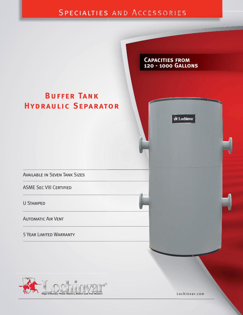
Buffer Tank Hydraulic Separator
Available in Seven Tank Sizes ASME Sec VIII Certified
U Stamped
Automatic Air Vent
5 Year Limited Warranty
LL o c h i n v a r .c o m
s and Accessoriess and Accessories
tor
Capacities from120 - 1000 Gallons
2
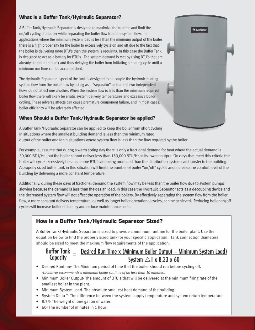
What is a Buffer Tank/Hydraulic Separator?
A Buffer Tank/Hydraulic Separator is designed to maximize the runtime and limit the
on/off cycling of a boiler while separating the boiler flow from the system flow. In
applications where the minimum system load is less than the minimum output of the boiler
there is a high propensity for the boiler to excessively cycle on and off due to the fact that
the boiler is delivering more BTU’s than the system is requiring. In this case the Buffer Tank
is designed to act as a battery for BTU’s. The system demand is met by using BTU’s that are
already stored in the tank and thus delaying the boiler from initiating a heating cycle until a
minimum run time can be accomplished.
The Hydraulic Separator aspect of the tank is designed to de-couple the hydronic heating
system flow from the boiler flow by acting as a “separator” so that the two independent
flows do not affect one another. When the system flow is less than the minimum required
boiler flow there will likely be erratic system delivery temperatures and excessive boiler
cycling. These adverse affects can cause premature component failure, and in most cases,
boiler efficiency will be adversely affected.
onic heating
ependent
equired
ler
es,
Desired Run Time x (Minimum Boiler Output – Minimum System Load)System T x 8.33 x 60
How is a Buffer Tank/Hydraulic Separator Sized?
A Buffer Tank/Hydraulic Separator is sized to provide a minimum runtime for the boiler plant. Use the
equation below to fi nd the properly sized tank for your specifi c application. Tank connection diameters
should be sized to meet the maximum fl ow requirements of the application.
• Desired Runtime- The Minimum period of time that the boiler should run before cycling off.
-Lochinvar recommends a minimum boiler runtime of no less than 10 minutes.
• Minimum Boiler Output- The amount of BTU’s that will be delivered at the minimum fi ring rate of the
smallest boiler in the plant.
• Minimum System Load- The absolute smallest heat demand of the building.
• System Delta T- The difference between the system supply temperature and system return temperature.
• 8.33- The weight of one gallon of water.
• 60- The number of minutes in 1 hour
When Should a Buffer Tank/Hydraulic Separator be applied?
A Buffer Tank/Hydraulic Separator can be applied to keep the boiler from short cycling
in situations where the smallest building demand is less than the minimum rated
output of the boiler and/or in situations where system flow is less than the flow required by the boiler.
For example, assume that during a warm spring day there is only a fractional demand for heat where the actual demand is
50,000 BTU/Hr., but the boiler cannot deliver less than 150,000 BTU/Hr at its lowest output. On days that meet this criteria the
boiler will cycle excessively because more BTU’s are being produced than the distribution system can transfer to the building.
A properly sized buffer tank in this situation will limit the number of boiler “on/off” cycles and increase the comfort level of the
building by delivering a more constant temperature.
Additionally, during these days of fractional demand the system flow may be less than the boiler flow due to system pumps
slowing because the demand is less than the design load. In this case the Hydraulic Separator acts as a decoupling device and
the decreased system flow will not affect the operation of the boilers. By effectively separating the system flow from the boiler
flow, a more constant delivery temperature, as well as longer boiler operational cycles, can be achieved. Reducing boiler on/off
cycles will increase boiler efficiency and reduce maintenance costs.
Buffer Tank Capacity =
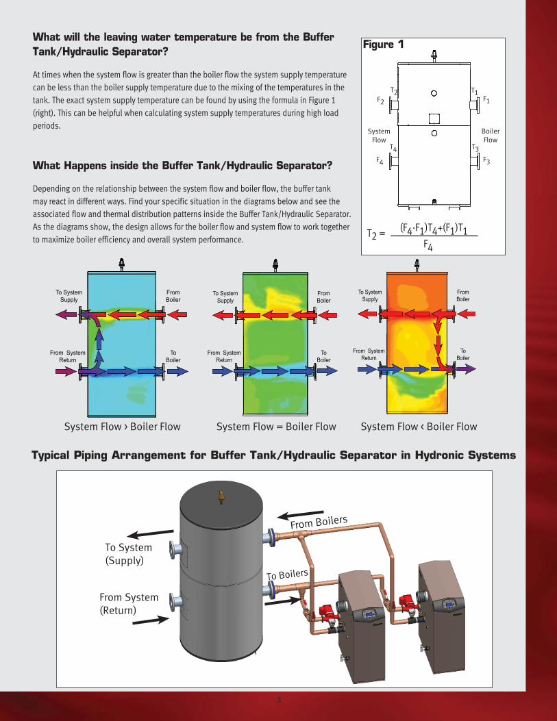
What will the leaving water temperature be from the Buffer
Tank/Hydraulic Separator?
At times when the system flow is greater than the boiler flow the system supply temperature
can be less than the boiler supply temperature due to the mixing of the temperatures in the
tank. The exact system supply temperature can be found by using the formula in Figure 1
(right). This can be helpful when calculating system supply temperatures during high load
periods.
What Happens inside the Buffer Tank/Hydraulic Separator?
Depending on the relationship between the system flow and boiler flow, the buffer tank
may react in different ways. Find your specific situation in the diagrams below and see the
associated flow and thermal distribution patterns inside the Buffer Tank/Hydraulic Separator.
As the diagrams show, the design allows for the boiler flow and system flow to work together
to maximize boiler efficiency and overall system performance.
Typical Piping Arrangement for Buffer Tank/Hydraulic Separator in Hydronic Systems
To System
(Supply)
From System
(Return)
To System Supply
From Boiler
From System Return
ToBoiler
To System Supply
From Boiler
From System Return
ToBoiler
To System Supply
From Boiler
From System Return
ToBoiler
From Boilers
To Boilers
System Flow > Boiler Flow System Flow = Boiler Flow System Flow < Boiler Flow
System
Flow
Boiler
Flow
F2
T1F1
T2
F4
T4 T3
F3
(F4-F1)T4+(F1)T1 F4
Figure 1
3
T2 =
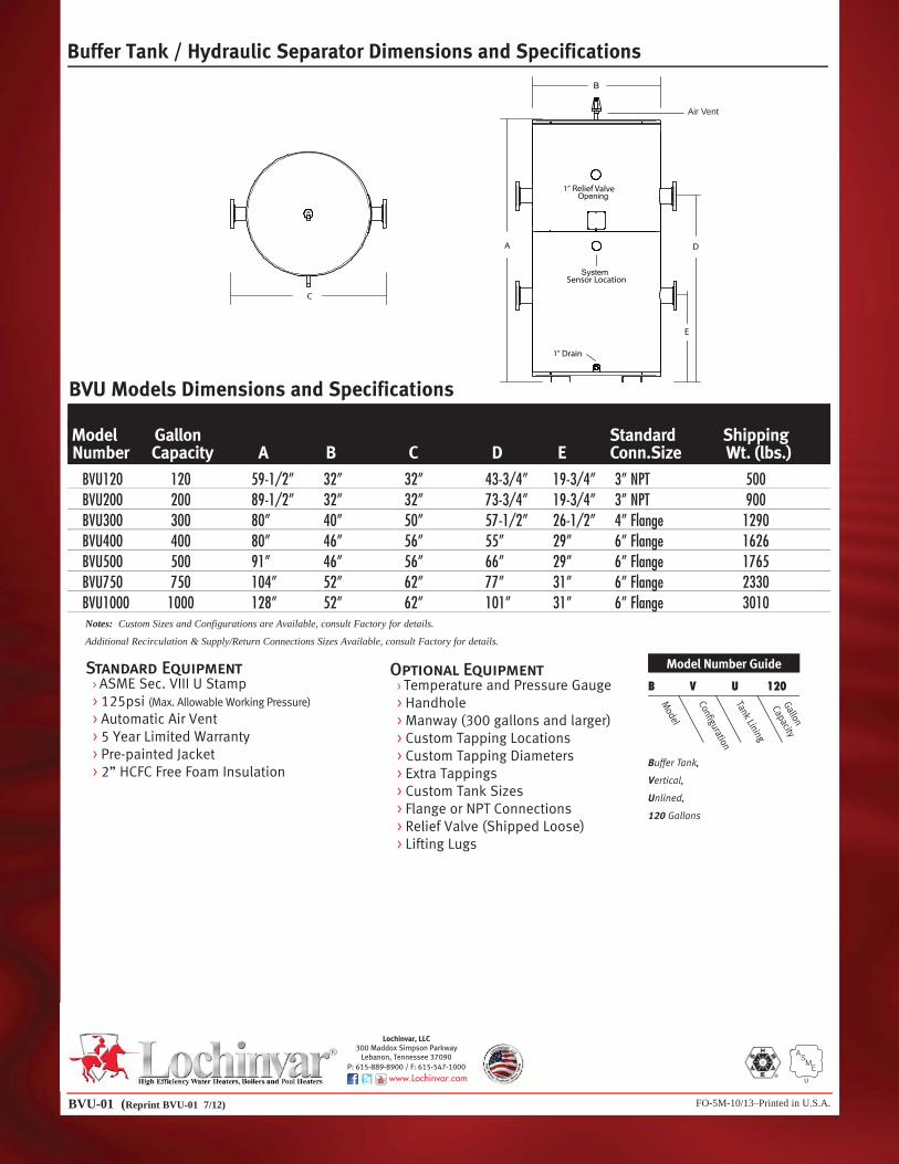
Buffer Tank / Hydraulic Separator Dimensions and Specifications
FO-5M-10/13–Printed in U.S.A.BVU-01 (Reprint BVU-01 7/12)
Model Gallon Standard Shipping Number Capacity A B C D E Conn.Size Wt. (lbs.)
BVU120 120 59-1/2” 32” 32” 43-3/4” 19-3/4” 3” NPT 500 BVU200 200 89-1/2” 32” 32” 73-3/4” 19-3/4” 3” NPT 900 BVU300 300 80” 40” 50” 57-1/2” 26-1/2” 4” Flange 1290 BVU400 400 80” 46” 56” 55” 29” 6” Flange 1626 BVU500 500 91” 46” 56” 66” 29” 6” Flange 1765 BVU750 750 104” 52” 62” 77” 31” 6” Flange 2330 BVU1000 1000 128” 52” 62” 101” 31” 6” Flange 3010
BVU Models Dimensions and Specifications
Notes: Custom Sizes and Configurations are Available, consult Factory for details.
Additional Recirculation & Supply/Return Connections Sizes Available, consult Factory for details.
Standard Equipment > ASME Sec. VIII U Stamp
> 125psi (Max. Allowable Working Pressure)
> Automatic Air Vent
> 5 Year Limited Warranty
> Pre-painted Jacket
> 2” HCFC Free Foam Insulation
Optional Equipment > Temperature and Pressure Gauge
> Handhole
> Manway (300 gallons and larger)
> Custom Tapping Locations
> Custom Tapping Diameters
> Extra Tappings
> Custom Tank Sizes
> Flange or NPT Connections
> Relief Valve (Shipped Loose)
> Lifting Lugs
Air Vent
Model Number Guide
B V U 120
Mod
el
Gallon
Capacity
Configuration
Tank Lining
Buffer Tank,
Vertical,
Unlined,
120 Gallons
U
Lochinvar, LLC 300 Maddox Simpson Parkway
Lebanon, Tennessee 37090P: 615-889-8900 / F: 615-547-1000
www.Lochinvar.com