Embed Size (px)
DESCRIPTION
Calculation Report
Citation preview
Page 1 of 46Kan de Ali - Tangki Buffer 200MT
TANK REPORT: Printed - 7/17/2012 5:09:49 PM
ETANK FULL REPORT - Tangki Buffer 200MTETank2000 Full 1.9.14 (26 Oct 2010)
TABLE OF CONTENTS PAGE 1
ETANK SETTINGS SUMMARY PAGE 2
SUMMARY OF DESIGN DATA AND REMARKS PAGE 3
SUMMARY OF RESULTS PAGE 5
ROOF DESIGN PAGE 8
SHELL COURSE DESIGN PAGE 17
BOTTOM HEAD DESIGN PAGE 28
SEISMIC CALCULATIONS PAGE 35
ANCHOR BOLT DESIGN PAGE 41
CAPACITIES AND WEIGHTS PAGE 45
MAWP & MAWV SUMMARY PAGE 46
Page 2 of 46Kan de Ali - Tangki Buffer 200MT
TANK REPORT: Printed - 7/17/2012 5:09:49 PM
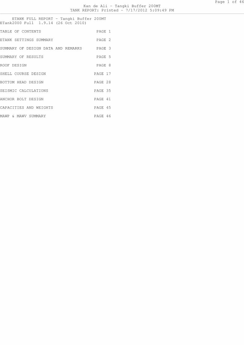
ETANK SETTINGS SUMMARY
To Change These ETank Settings, Go To Tools->Option s, Behavior Tab.--------------------------------------------------- ------------------- No 650 Appendix F Calcs when Tank P = 0 -> Defa ult : False -> This Tank : False Repad 650 Design Basis -> Default for Tank Roof Nozzles : t-Ba sis = Roof t-Calc -> This Tank : Use API Default 1/4 in. Show MAWP / MAWV Calcs : True Enforce API Minimum thicknesses : True Enforce API Maximum Roof thickness : True Enforce Minimum Self Supp. Cone Pitch (2 in 12) : True Force Non-Annular Btm. to Meet API-650 5.5.1 : False Set t.actual to t.required Values : False Maximum 650 App. S or App. M Multiplier is 1 : True Enforce API Maximum Nozzle Sizes : True Max. Self Supported Roof thickness : 0.5 in. Max. Tank Corr. Allowance : 0.5 in. External pressure calcs subtract C.A. per V.5 : False Use Gauge Material for min thicknesses : False Enforce API Minimum Live Load : True Enforce API Minimum Anchor Chair Design Load = Bolt Yield Load : True
Page 3 of 46Kan de Ali - Tangki Buffer 200MT
TANK REPORT: Printed - 7/17/2012 5:09:49 PM
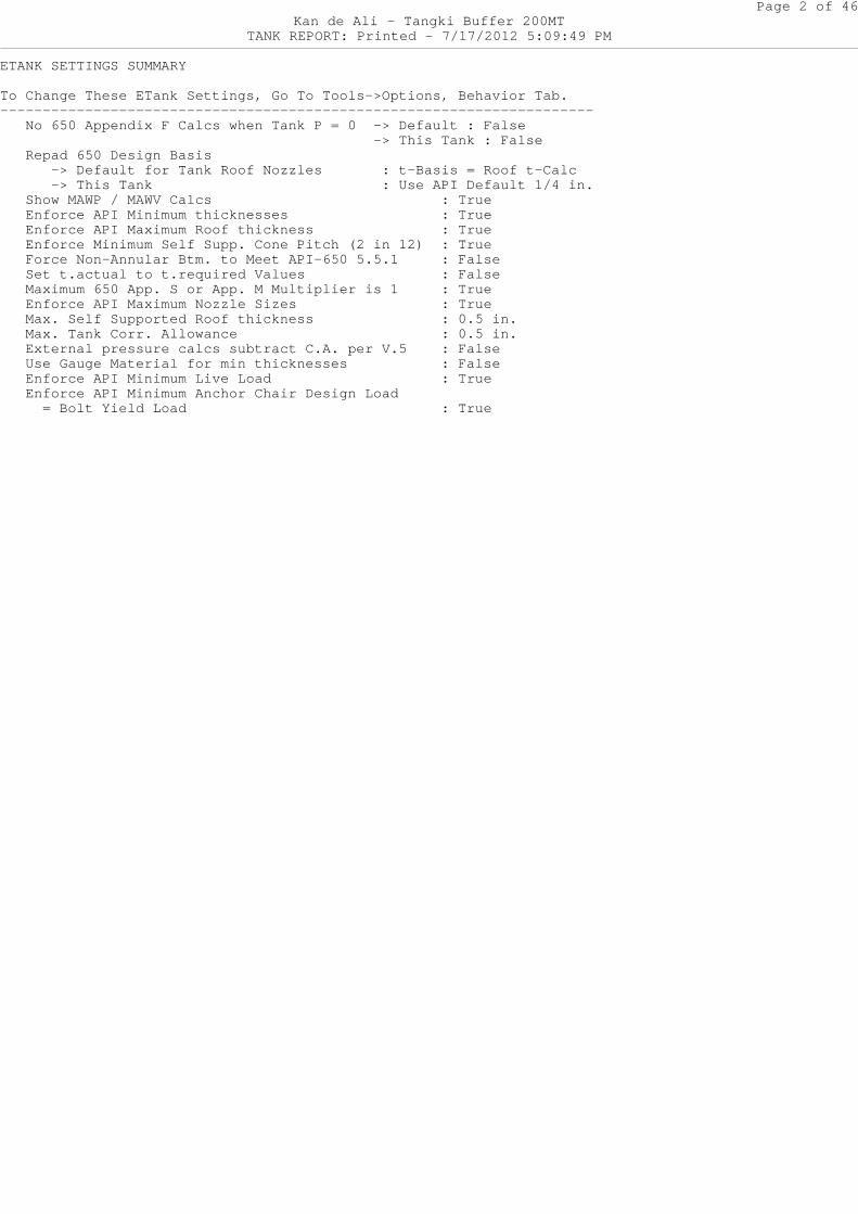
SUMMARY OF DESIGN DATA and REMARKS
Job : Tangki Buffer 200MTDate of Calcs. : 7/17/2012 , 05:09 PMMfg. or Insp. Date : 6/19/2012Designer : GandhiProject : Smart RefineryPlant : RungkutPlant Location : SurabayaSite : SurabayaDesign Basis : API-650 11th Edition, Addendu m 2, Nov 2009
--------------------------------------------------- -------------------- TANK NAMEPLATE INFORMATION
--------------------------------------------------- -------------------- Operating Ratio: 0.4- Design Standard:- API-650 11th Edition, Addendum 2, Nov 2009 -- (None) -- Roof : A-240 Type 304L: 0.236in. -- Shell (8): A-240 Type 304: 0.236in. -- Shell (7): A-240 Type 304: 0.236in. -- Shell (6): A-240 Type 304: 0.236in. -- Shell (5): A-240 Type 304: 0.236in. -- Shell (4): A-240 Type 304: 0.315in. -- Shell (3): A-240 Type 304: 0.315in. -- Shell (2): A-240 Type 304: 0.315in. -- Shell (1): A-240 Type 304: 0.315in. -- Bottom : A-240 Type 304L: 0.47in. -
--------------------------------------------------- -------------------
Design Internal Pressure = 1 PSI or 27.71 IN. H2ODesign External Pressure = 0 PSI or 0 IN. H2O
MAWP = 0 PSI or 0 IN. H2OMAWV = 0 PSI or 0 IN. H2O
OD of Tank = 17.834 ftShell Height = 32 ftS.G. of Contents = 0.9Max. Liq. Level = 32 ft
Design Temperature = 104 °FTank Joint Efficiency = 0.7
Ground Snow Load = 0 lbf/ft^2Roof Live Load = 25 lbf/ft^2Design Roof Dead Load = 0 lbf/ft^2
Page 4 of 46Kan de Ali - Tangki Buffer 200MT
TANK REPORT: Printed - 7/17/2012 5:09:49 PM
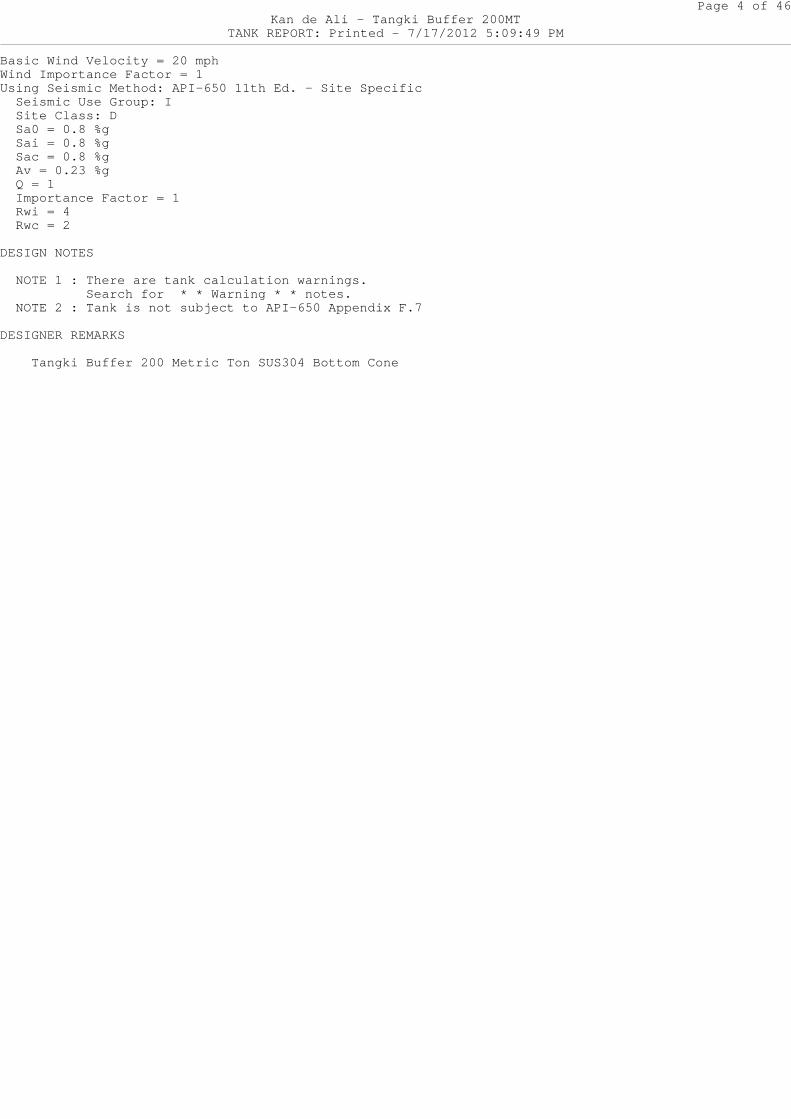
Basic Wind Velocity = 20 mphWind Importance Factor = 1Using Seismic Method: API-650 11th Ed. - Site Speci fic Seismic Use Group: I Site Class: D Sa0 = 0.8 %g Sai = 0.8 %g Sac = 0.8 %g Av = 0.23 %g Q = 1 Importance Factor = 1 Rwi = 4 Rwc = 2
DESIGN NOTES
NOTE 1 : There are tank calculation warnings. Search for * * Warning * * notes. NOTE 2 : Tank is not subject to API-650 Appendix F.7
DESIGNER REMARKS
Tangki Buffer 200 Metric Ton SUS304 Bottom Cone
Page 5 of 46Kan de Ali - Tangki Buffer 200MT
TANK REPORT: Printed - 7/17/2012 5:09:49 PM
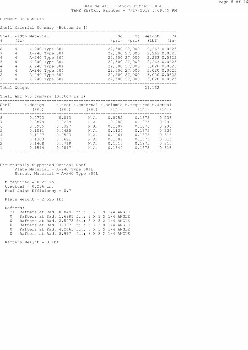
SUMMARY OF RESULTS
Shell Material Summary (Bottom is 1)--------------------------------------------------- ---------------------Shell Width Material Sd St Weight CA# (ft) (psi) (psi) (lbf) (in)--------------------------------------------------- ---------------------8 4 A-240 Type 304 22,500 27,000 2,263 0.06257 4 A-240 Type 304 22,500 27,000 2,263 0.06256 4 A-240 Type 304 22,500 27,000 2,263 0.06255 4 A-240 Type 304 22,500 27,000 2,263 0.06254 4 A-240 Type 304 22,500 27,000 3,020 0.06253 4 A-240 Type 304 22,500 27,000 3,020 0.06252 4 A-240 Type 304 22,500 27,000 3,020 0.06251 4 A-240 Type 304 22,500 27,000 3,020 0.0625--------------------------------------------------- ---------------------Total Weight 21,132
Shell API 650 Summary (Bottom is 1)--------------------------------------------------- -------------------Shell t.design t.test t.external t.seismic t.required t.actual# (in.) (in.) (in.) (in.) (in.) (in.)--------------------------------------------------- -------------------8 0.0773 0.013 N.A. 0.0752 0.1875 0.2367 0.0879 0.0228 N.A. 0.088 0.1875 0.2366 0.0985 0.0327 N.A. 0.1007 0.1875 0.2365 0.1091 0.0425 N.A. 0.1134 0.1875 0.2364 0.1197 0.0523 N.A. 0.1261 0.1875 0.3153 0.1303 0.0621 N.A. 0.1389 0.1875 0.3152 0.1408 0.0719 N.A. 0.1516 0.1875 0.3151 0.1514 0.0817 N.A. 0.1644 0.1875 0.315--------------------------------------------------- -------------------
Structurally Supported Conical Roof Plate Material = A-240 Type 304L, Struct. Material = A-240 Type 304L
t.required = 0.25 in. t.actual = 0.236 in. Roof Joint Efficiency = 0.7
Plate Weight = 2,525 lbf
Rafters: 21 Rafters at Rad. 0.8493 ft.: 3 X 3 X 1/4 ANG LE 0 Rafters at Rad. 1.6985 ft.: 3 X 3 X 1/4 ANG LE 0 Rafters at Rad. 2.5478 ft.: 3 X 3 X 1/4 ANG LE 0 Rafters at Rad. 3.397 ft.: 3 X 3 X 1/4 ANG LE 0 Rafters at Rad. 4.2463 ft.: 3 X 3 X 1/4 ANG LE 0 Rafters at Rad. 8.917 ft.: 3 X 3 X 1/4 ANG LE
Rafters Weight = 0 lbf
Page 6 of 46Kan de Ali - Tangki Buffer 200MT
TANK REPORT: Printed - 7/17/2012 5:09:49 PM
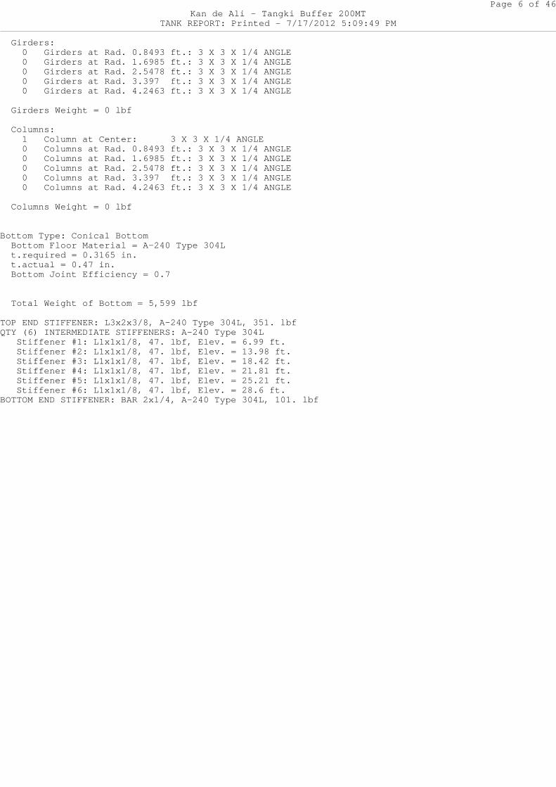
Girders: 0 Girders at Rad. 0.8493 ft.: 3 X 3 X 1/4 ANG LE 0 Girders at Rad. 1.6985 ft.: 3 X 3 X 1/4 ANG LE 0 Girders at Rad. 2.5478 ft.: 3 X 3 X 1/4 ANG LE 0 Girders at Rad. 3.397 ft.: 3 X 3 X 1/4 ANG LE 0 Girders at Rad. 4.2463 ft.: 3 X 3 X 1/4 ANG LE
Girders Weight = 0 lbf
Columns: 1 Column at Center: 3 X 3 X 1/4 ANGLE 0 Columns at Rad. 0.8493 ft.: 3 X 3 X 1/4 ANG LE 0 Columns at Rad. 1.6985 ft.: 3 X 3 X 1/4 ANG LE 0 Columns at Rad. 2.5478 ft.: 3 X 3 X 1/4 ANG LE 0 Columns at Rad. 3.397 ft.: 3 X 3 X 1/4 ANG LE 0 Columns at Rad. 4.2463 ft.: 3 X 3 X 1/4 ANG LE
Columns Weight = 0 lbf
Bottom Type: Conical Bottom Bottom Floor Material = A-240 Type 304L t.required = 0.3165 in. t.actual = 0.47 in. Bottom Joint Efficiency = 0.7
Total Weight of Bottom = 5,599 lbf
TOP END STIFFENER: L3x2x3/8, A-240 Type 304L, 351. lbfQTY (6) INTERMEDIATE STIFFENERS: A-240 Type 304L Stiffener #1: L1x1x1/8, 47. lbf, Elev. = 6.99 ft . Stiffener #2: L1x1x1/8, 47. lbf, Elev. = 13.98 f t. Stiffener #3: L1x1x1/8, 47. lbf, Elev. = 18.42 f t. Stiffener #4: L1x1x1/8, 47. lbf, Elev. = 21.81 f t. Stiffener #5: L1x1x1/8, 47. lbf, Elev. = 25.21 f t. Stiffener #6: L1x1x1/8, 47. lbf, Elev. = 28.6 ft .BOTTOM END STIFFENER: BAR 2x1/4, A-240 Type 304L, 1 01. lbf
Page 7 of 46Kan de Ali - Tangki Buffer 200MT
TANK REPORT: Printed - 7/17/2012 5:09:49 PM
SUPPORTED CONICAL ROOF (from Brownell & Young)
Roof Plate Material: A-240 Type 304L, Sd = 20,928 PSI, Fy = 24,856 PSI « (API-650 Table S-2a)Structural Material: A-240 Type 304L, Sd = 20,928 PSI, Fy = 24,856 PSI « (API-650 Table S-2a)
R = 8.917 ft pt = 0.75 in/ft (Cone Roof Pitch)
Theta = ATAN(pt/12) = ATAN(0.0625) = 3.5763 degre es
Ap_Vert = Vertical Projected Area of Roof = pt*OD^2/48 = 0.75*17.834^2/48 = 4.97 ft^2
Horizontal Projected Area of Roof (Per API-650 5. 2.1.f)
Xw = Moment Arm of UPLIFT wind force on roof = 0.5*OD = 0.5*17.834 = 8.917 ft Ap = Projected Area of roof for wind moment = PI*R^2 = PI*8.917^2 = 249.797 ft^2
S = Ground Snow Load = 0 lbf/ft^2 Sb = Balanced Design Snow Load = 0 lbf/ft^2 Su = Unbalanced Design Snow Load = 0 lbf/ft^2
Dead_Load = Insulation + Plate_Weight + Added_Dea d_Load = (8)(4/12) + 10.1102 + 0 = 12.7769 lbf/ft^2
Roof Loads (per API-650 Appendix R)
Pe = PV*144 = 0*144 = 0 lbf/ft^2
e.1b = DL + MAX(Sb,Lr) + 0.4*Pe = 12.7769 + 25 + 0.4*0 = 37.777 lbf/ft^2
e.2b = DL + Pe + 0.4*MAX(Sb,Lr) = 12.7769 + 0 + 0.4*25 = 22.777 lbf/ft^2
T = Balanced Roof Design Load (per API-650 Append ix R) = MAX(e.1b,e.2b) = 37.777 lbf/ft^2
e.1u = DL + MAX(Su,Lr) + 0.4*Pe = 12.7769 + 25 + 0.4*0 = 37.777 lbf/ft^2
e.2u = DL + Pe + 0.4*MAX(Su,Lr) = 12.7769 + 0 + 0.4*25 = 22.777 lbf/ft^2
Page 8 of 46Kan de Ali - Tangki Buffer 200MT
TANK REPORT: Printed - 7/17/2012 5:09:49 PM
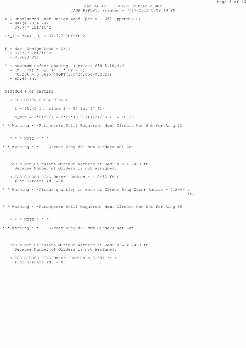
U = Unbalanced Roof Design Load (per API-650 Appe ndix R) = MAX(e.1u,e.2u) = 37.777 lbf/ft^2
Lr_1 = MAX(T,U) = 37.777 lbf/ft^2
P = Max. Design Load = Lr_1 = 37.777 lbf/ft^2 = 0.2623 PSI
l = Maximum Rafter Spacing (Per API-650 5.10.4.4 ) = (t - ca) * SQRT(1.5 * Fy / P) = (0.236 - 0.0625)*SQRT(1.5*24,856/0.2623) = 65.41 in.
MINIMUM # OF RAFTERS
< FOR OUTER SHELL RING >
l = 65.41 in. since l < 84 in. (7 ft)
N_min = 2*PI*R/l = 2*PI*(8.917)(12)/65.41 = 1 0.28
* * Warning * *Parameters Still Required: Num. Gir ders Not Set for Ring #5
* * * NOTE * * *
* * Warning * * Girder Ring #5: Num Girders Not Set
Could Not Calculate Minimum Rafters at Radius = 4.2463 ft. Because Number of Girders is not Assigned.
< FOR GIRDER RING Outer Radius = 4.2463 ft > # of Girders (N) = 0
* * Warning * *Girder quantity is zero at Girder R ing Outer Radius = 4.2463 « ft.
* * Warning * *Parameters Still Required: Num. Gir ders Not Set for Ring #5
* * * NOTE * * *
* * Warning * * Girder Ring #5: Num Girders Not Set
Could Not Calculate Minimum Rafters at Radius = 4.2463 ft. Because Number of Girders is not Assigned.
< FOR GIRDER RING Outer Radius = 3.397 ft > # of Girders (N) = 0
Page 9 of 46Kan de Ali - Tangki Buffer 200MT
TANK REPORT: Printed - 7/17/2012 5:09:49 PM
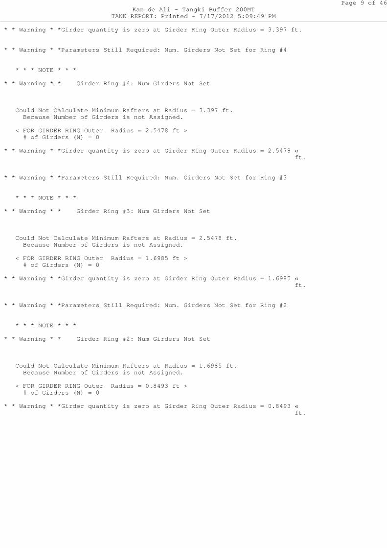
* * Warning * *Girder quantity is zero at Girder R ing Outer Radius = 3.397 ft.
* * Warning * *Parameters Still Required: Num. Gir ders Not Set for Ring #4
* * * NOTE * * *
* * Warning * * Girder Ring #4: Num Girders Not Set
Could Not Calculate Minimum Rafters at Radius = 3.397 ft. Because Number of Girders is not Assigned.
< FOR GIRDER RING Outer Radius = 2.5478 ft > # of Girders (N) = 0
* * Warning * *Girder quantity is zero at Girder R ing Outer Radius = 2.5478 « ft.
* * Warning * *Parameters Still Required: Num. Gir ders Not Set for Ring #3
* * * NOTE * * *
* * Warning * * Girder Ring #3: Num Girders Not Set
Could Not Calculate Minimum Rafters at Radius = 2.5478 ft. Because Number of Girders is not Assigned.
< FOR GIRDER RING Outer Radius = 1.6985 ft > # of Girders (N) = 0
* * Warning * *Girder quantity is zero at Girder R ing Outer Radius = 1.6985 « ft.
* * Warning * *Parameters Still Required: Num. Gir ders Not Set for Ring #2
* * * NOTE * * *
* * Warning * * Girder Ring #2: Num Girders Not Set
Could Not Calculate Minimum Rafters at Radius = 1.6985 ft. Because Number of Girders is not Assigned.
< FOR GIRDER RING Outer Radius = 0.8493 ft > # of Girders (N) = 0
* * Warning * *Girder quantity is zero at Girder R ing Outer Radius = 0.8493 « ft.
Page 10 of 46Kan de Ali - Tangki Buffer 200MT
TANK REPORT: Printed - 7/17/2012 5:09:49 PM
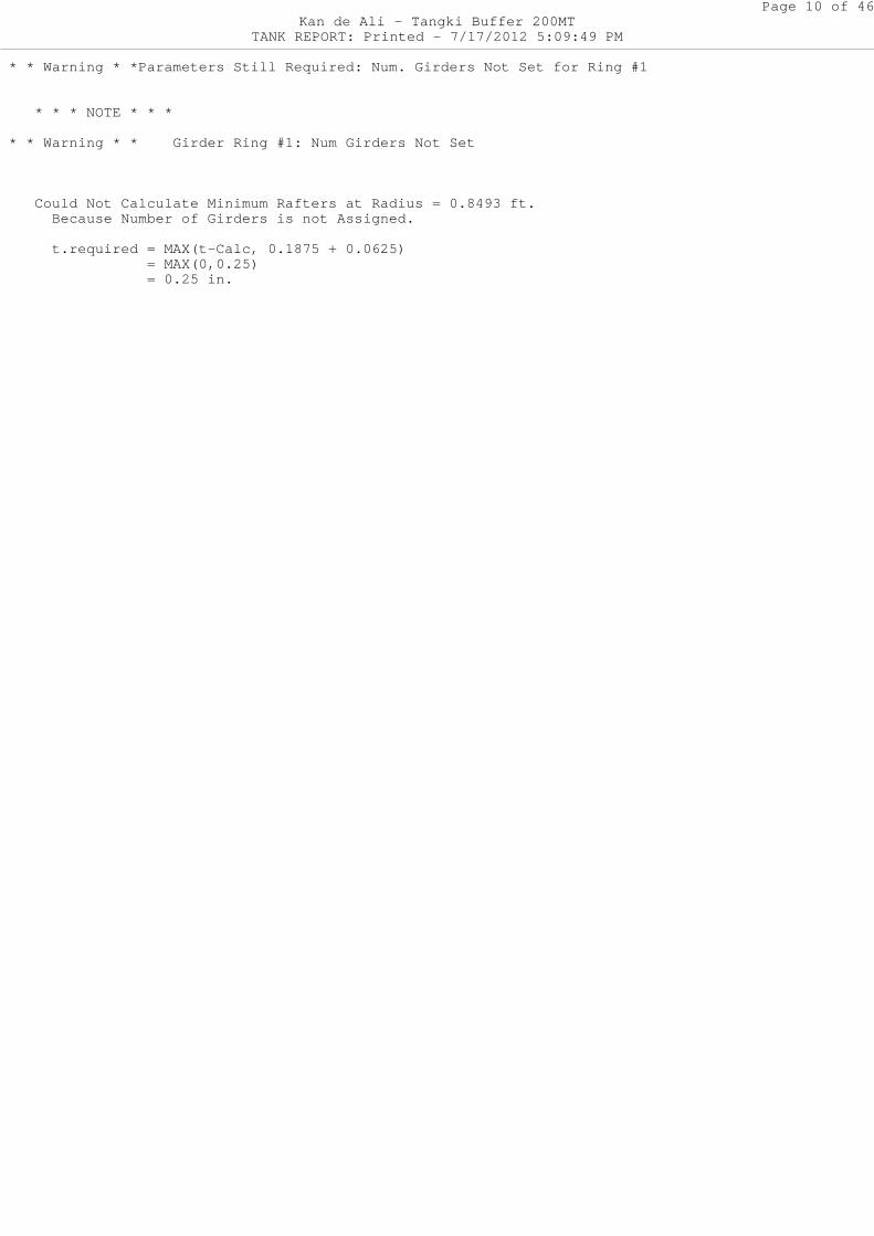
* * Warning * *Parameters Still Required: Num. Gir ders Not Set for Ring #1
* * * NOTE * * *
* * Warning * * Girder Ring #1: Num Girders Not Set
Could Not Calculate Minimum Rafters at Radius = 0.8493 ft. Because Number of Girders is not Assigned.
t.required = MAX(t-Calc, 0.1875 + 0.0625) = MAX(0,0.25) = 0.25 in.
Page 11 of 46Kan de Ali - Tangki Buffer 200MT
TANK REPORT: Printed - 7/17/2012 5:09:49 PM
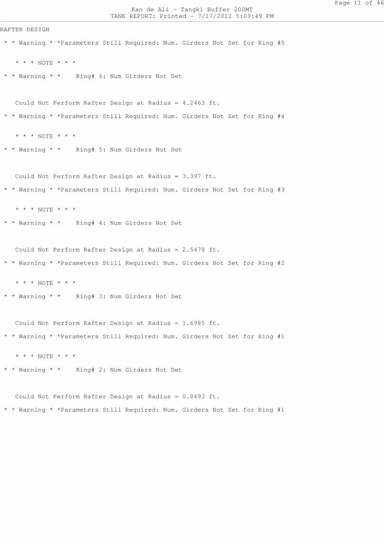
RAFTER DESIGN
* * Warning * *Parameters Still Required: Num. Gir ders Not Set for Ring #5
* * * NOTE * * *
* * Warning * * Ring# 6: Num Girders Not Set
Could Not Perform Rafter Design at Radius = 4.2 463 ft.
* * Warning * *Parameters Still Required: Num. Gir ders Not Set for Ring #4
* * * NOTE * * *
* * Warning * * Ring# 5: Num Girders Not Set
Could Not Perform Rafter Design at Radius = 3.3 97 ft.
* * Warning * *Parameters Still Required: Num. Gir ders Not Set for Ring #3
* * * NOTE * * *
* * Warning * * Ring# 4: Num Girders Not Set
Could Not Perform Rafter Design at Radius = 2.5 478 ft.
* * Warning * *Parameters Still Required: Num. Gir ders Not Set for Ring #2
* * * NOTE * * *
* * Warning * * Ring# 3: Num Girders Not Set
Could Not Perform Rafter Design at Radius = 1.6 985 ft.
* * Warning * *Parameters Still Required: Num. Gir ders Not Set for Ring #1
* * * NOTE * * *
* * Warning * * Ring# 2: Num Girders Not Set
Could Not Perform Rafter Design at Radius = 0.8 493 ft.
* * Warning * *Parameters Still Required: Num. Gir ders Not Set for Ring #1
Page 12 of 46Kan de Ali - Tangki Buffer 200MT
TANK REPORT: Printed - 7/17/2012 5:09:49 PM
* * * NOTE * * *
* * Warning * * Ring #1: Num Girders Not Set
Could Not Perform Rafter Design at Radius = 0.8 493 ft.
Page 13 of 46Kan de Ali - Tangki Buffer 200MT
TANK REPORT: Printed - 7/17/2012 5:09:49 PM
GIRDER DESIGN
* * * NOTE * * *
* * Warning * *Ring #4: Num. Girders Not yet Assig ned.
* * Warning * *Ring #4: Num. Girders Not yet Assig ned.
Could Not Perform Girder Design at Radius = 3.3 97 ft.
* * * NOTE * * *
* * Warning * *Ring #3: Num. Girders Not yet Assig ned.
* * Warning * *Ring #3: Num. Girders Not yet Assig ned.
Could Not Perform Girder Design at Radius = 2.5 478 ft.
* * * NOTE * * *
* * Warning * *Ring #2: Num. Girders Not yet Assig ned.
* * Warning * *Ring #2: Num. Girders Not yet Assig ned.
Could Not Perform Girder Design at Radius = 1.6 985 ft.
* * * NOTE * * *
* * Warning * *Ring #1: Num. Girders Not yet Assig ned.
* * Warning * *Ring #1: Num. Girders Not yet Assig ned.
Could Not Perform Girder Design at Radius = 0.8 493 ft.
* * * NOTE * * *
* * Warning * *Ring #1: Num. Girders Not yet Assig ned.
* * Warning * *Ring #1: Num. Girders Not yet Assig ned.
Could Not Perform Girder Design at Radius = 0.8 493 ft.
Page 14 of 46Kan de Ali - Tangki Buffer 200MT
TANK REPORT: Printed - 7/17/2012 5:09:49 PM
COLUMN DESIGN
* * * NOTE * * *
* * Warning * *Ring #6: Num. Rafters Not yet Assig ned.
* * Warning * *Ring #6: Num. Rafters Not yet Assig ned.
Could Not Perform Column Design at Radius = 8.9 17 ft.
* * * NOTE * * *
* * Warning * *Ring #5: Num. Girders Not yet Assig ned.
* * Warning * *Ring #5: Num. Girders Not yet Assig ned.
Could Not Perform Column Design at Radius = 4.2 463 ft.
* * * NOTE * * *
* * Warning * *Ring #4: Num. Girders Not yet Assig ned.
* * Warning * *Ring #4: Num. Girders Not yet Assig ned.
Could Not Perform Column Design at Radius = 3.3 97 ft.
* * * NOTE * * *
* * Warning * *Ring #3: Num. Girders Not yet Assig ned.
* * Warning * *Ring #3: Num. Girders Not yet Assig ned.
Could Not Perform Column Design at Radius = 2.5 478 ft.
* * * NOTE * * *
* * Warning * *Ring #2: Num. Girders Not yet Assig ned.
* * Warning * *Ring #2: Num. Girders Not yet Assig ned.
Could Not Perform Column Design at Radius = 1.6 985 ft.
* * * NOTE * * *
Page 15 of 46Kan de Ali - Tangki Buffer 200MT
TANK REPORT: Printed - 7/17/2012 5:09:49 PM
* * Warning * *Ring #1: Num. Girders Not yet Assig ned.
* * Warning * *Ring #1: Num. Girders Not yet Assig ned.
Could Not Perform Column Design at Radius = 0.8 493 ft.
Roof_Area = 36*PI*OD^2/COS(Theta) = 36*PI*(17.834)^2/COS() = 36,041 in^2
ROOF WEIGHT
Weight of Roof Plates = (density)(t)(PI/4)(12*OD - t)^2/COS( Theta) = (0.2975)(0.236)(PI/4)(214.008 - 0.23 6)^2/COS(3.5763) = 2,525 lbf (New) = 1,856 lbf (Corroded)
Weight of Roof Plates supported by shell = 1,146 lbf (New) = 843 lbf (Corroded)
Weight of Rafters = 0 lbf (New) Weight of Girders = 0 lbf (New) Weight of Columns = 0 lbf (New)
Total Weight of Roof = 2,525 lbf (New) = 1,856 lbf (Corroded)
<Actual Participating Area of Roof-to-Shell Junctur e>
(From API-650 Figure F-2) Wc = 0.6 * SQRT[Rc * (t-CA)] (Top Shell Cours e) = 0.6 * SQRT[106.768 * (0.236 - 0.0625)] = 2.5824 in.
(From API-650 Figure F-2) Wh = 0.3 * SQRT[R2 * (t-CA)] (or 12", whichever is less) = 0.3 * SQRT[1,715 * (0.236 - 0.0625)] = MIN(5.1755, 12) = 5.1755 in.
Top End Stiffener: L3x2x3/8 Aa = (Cross-sectional Area of Top End Stiffener) = 1.73 in^2
Using API-650 Fig. F-2, Detail d End Stiffener D etail
Ashell = Contributing Area due to shell plates = Wc*(t_shell - CA) = 2.5824 * (0.236 - 0.0625) = 0.448 in^2
Page 16 of 46Kan de Ali - Tangki Buffer 200MT
TANK REPORT: Printed - 7/17/2012 5:09:50 PM
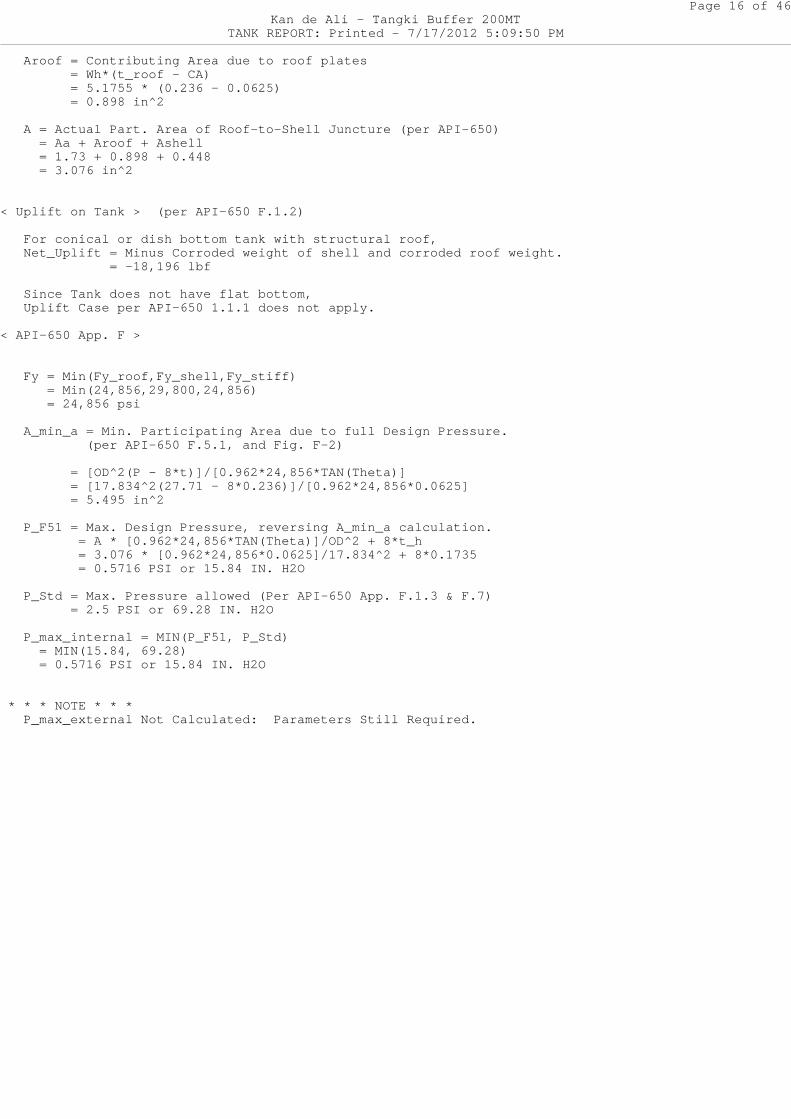
Aroof = Contributing Area due to roof plates = Wh*(t_roof - CA) = 5.1755 * (0.236 - 0.0625) = 0.898 in^2
A = Actual Part. Area of Roof-to-Shell Juncture (per API-650) = Aa + Aroof + Ashell = 1.73 + 0.898 + 0.448 = 3.076 in^2
< Uplift on Tank > (per API-650 F.1.2)
For conical or dish bottom tank with structural roof, Net_Uplift = Minus Corroded weight of shell and corroded roof weight. = -18,196 lbf
Since Tank does not have flat bottom, Uplift Case per API-650 1.1.1 does not apply.
< API-650 App. F >
Fy = Min(Fy_roof,Fy_shell,Fy_stiff) = Min(24,856,29,800,24,856) = 24,856 psi
A_min_a = Min. Participating Area due to full De sign Pressure. (per API-650 F.5.1, and Fig. F-2)
= [OD^2(P - 8*t)]/[0.962*24,856*TAN(Theta) ] = [17.834^2(27.71 - 8*0.236)]/[0.962*24,85 6*0.0625] = 5.495 in^2
P_F51 = Max. Design Pressure, reversing A_min_a calculation. = A * [0.962*24,856*TAN(Theta)]/OD^2 + 8* t_h = 3.076 * [0.962*24,856*0.0625]/17.834^2 + 8*0.1735 = 0.5716 PSI or 15.84 IN. H2O
P_Std = Max. Pressure allowed (Per API-650 App. F.1.3 & F.7) = 2.5 PSI or 69.28 IN. H2O
P_max_internal = MIN(P_F51, P_Std) = MIN(15.84, 69.28) = 0.5716 PSI or 15.84 IN. H2O
* * * NOTE * * * P_max_external Not Calculated: Parameters Still Required.
Page 17 of 46Kan de Ali - Tangki Buffer 200MT
TANK REPORT: Printed - 7/17/2012 5:09:50 PM
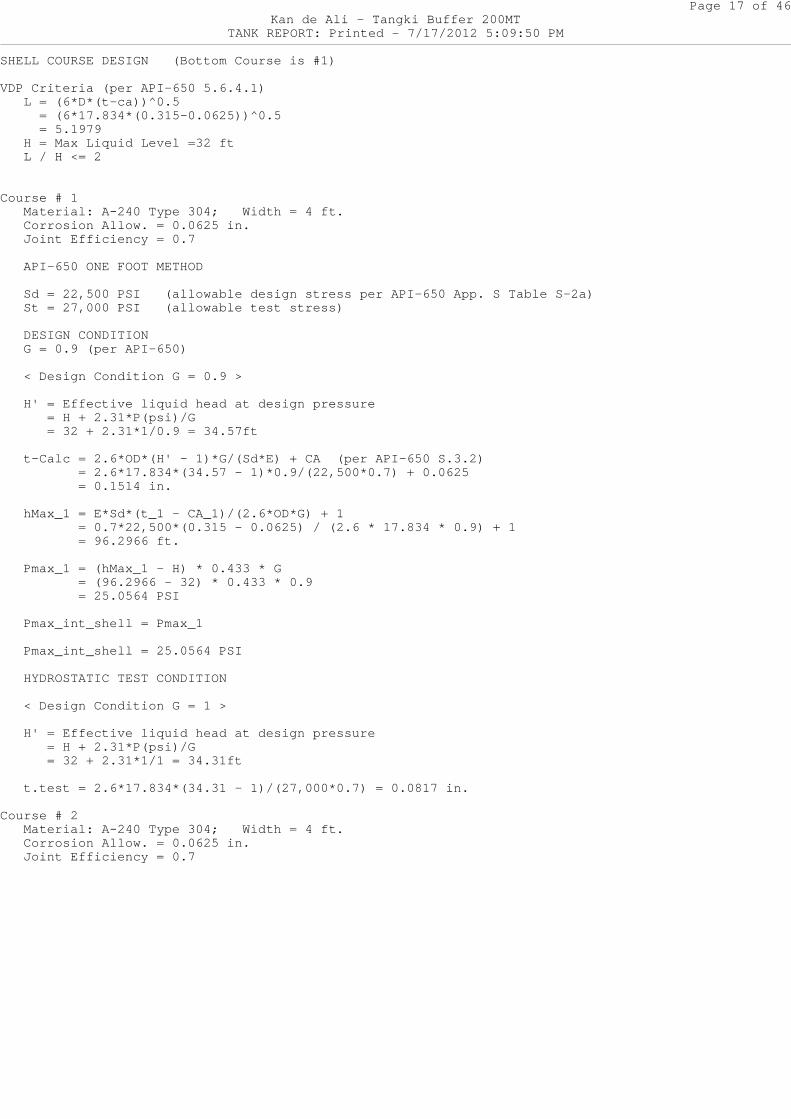
SHELL COURSE DESIGN (Bottom Course is #1)
VDP Criteria (per API-650 5.6.4.1) L = (6*D*(t-ca))^0.5 = (6*17.834*(0.315-0.0625))^0.5 = 5.1979 H = Max Liquid Level =32 ft L / H <= 2
Course # 1 Material: A-240 Type 304; Width = 4 ft.
Corrosion Allow. = 0.0625 in. Joint Efficiency = 0.7
API-650 ONE FOOT METHOD
Sd = 22,500 PSI (allowable design stress per A PI-650 App. S Table S-2a) St = 27,000 PSI (allowable test stress)
DESIGN CONDITION G = 0.9 (per API-650)
< Design Condition G = 0.9 >
H' = Effective liquid head at design pressure = H + 2.31*P(psi)/G = 32 + 2.31*1/0.9 = 34.57ft
t-Calc = 2.6*OD*(H' - 1)*G/(Sd*E) + CA (per API -650 S.3.2) = 2.6*17.834*(34.57 - 1)*0.9/(22,500*0.7) + 0.0625 = 0.1514 in.
hMax_1 = E*Sd*(t_1 - CA_1)/(2.6*OD*G) + 1 = 0.7*22,500*(0.315 - 0.0625) / (2.6 * 17 .834 * 0.9) + 1 = 96.2966 ft.
Pmax_1 = (hMax_1 - H) * 0.433 * G = (96.2966 - 32) * 0.433 * 0.9 = 25.0564 PSI
Pmax_int_shell = Pmax_1
Pmax_int_shell = 25.0564 PSI
HYDROSTATIC TEST CONDITION
< Design Condition G = 1 >
H' = Effective liquid head at design pressure = H + 2.31*P(psi)/G = 32 + 2.31*1/1 = 34.31ft
t.test = 2.6*17.834*(34.31 - 1)/(27,000*0.7) = 0 .0817 in.
Course # 2 Material: A-240 Type 304; Width = 4 ft.
Corrosion Allow. = 0.0625 in. Joint Efficiency = 0.7
Page 18 of 46Kan de Ali - Tangki Buffer 200MT
TANK REPORT: Printed - 7/17/2012 5:09:50 PM
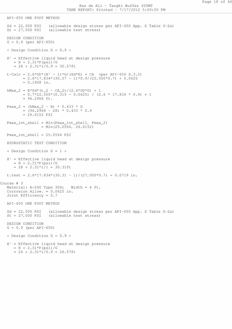
API-650 ONE FOOT METHOD
Sd = 22,500 PSI (allowable design stress per A PI-650 App. S Table S-2a) St = 27,000 PSI (allowable test stress)
DESIGN CONDITION G = 0.9 (per API-650)
< Design Condition G = 0.9 >
H' = Effective liquid head at design pressure = H + 2.31*P(psi)/G = 28 + 2.31*1/0.9 = 30.57ft
t-Calc = 2.6*OD*(H' - 1)*G/(Sd*E) + CA (per API -650 S.3.2) = 2.6*17.834*(30.57 - 1)*0.9/(22,500*0.7) + 0.0625 = 0.1408 in.
hMax_2 = E*Sd*(t_2 - CA_2)/(2.6*OD*G) + 1 = 0.7*22,500*(0.315 - 0.0625) / (2.6 * 17 .834 * 0.9) + 1 = 96.2966 ft.
Pmax_2 = (hMax_2 - H) * 0.433 * G = (96.2966 - 28) * 0.433 * 0.9 = 26.6152 PSI
Pmax_int_shell = Min(Pmax_int_shell, Pmax_2) = Min(25.0564, 26.6152)
Pmax_int_shell = 25.0564 PSI
HYDROSTATIC TEST CONDITION
< Design Condition G = 1 >
H' = Effective liquid head at design pressure = H + 2.31*P(psi)/G = 28 + 2.31*1/1 = 30.31ft
t.test = 2.6*17.834*(30.31 - 1)/(27,000*0.7) = 0 .0719 in.
Course # 3 Material: A-240 Type 304; Width = 4 ft.
Corrosion Allow. = 0.0625 in. Joint Efficiency = 0.7
API-650 ONE FOOT METHOD
Sd = 22,500 PSI (allowable design stress per A PI-650 App. S Table S-2a) St = 27,000 PSI (allowable test stress)
DESIGN CONDITION G = 0.9 (per API-650)
< Design Condition G = 0.9 >
H' = Effective liquid head at design pressure = H + 2.31*P(psi)/G = 24 + 2.31*1/0.9 = 26.57ft
Page 19 of 46Kan de Ali - Tangki Buffer 200MT
TANK REPORT: Printed - 7/17/2012 5:09:50 PM
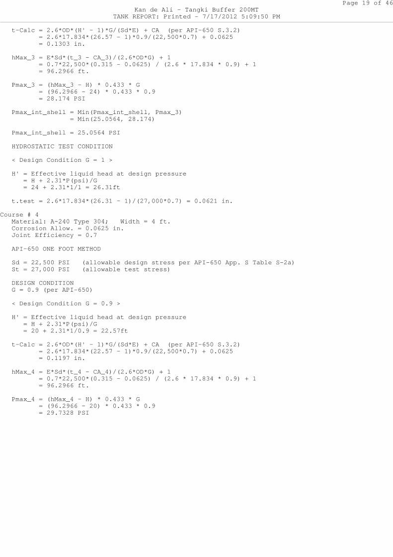
t-Calc = 2.6*OD*(H' - 1)*G/(Sd*E) + CA (per API -650 S.3.2) = 2.6*17.834*(26.57 - 1)*0.9/(22,500*0.7) + 0.0625 = 0.1303 in.
hMax_3 = E*Sd*(t_3 - CA_3)/(2.6*OD*G) + 1 = 0.7*22,500*(0.315 - 0.0625) / (2.6 * 17 .834 * 0.9) + 1 = 96.2966 ft.
Pmax_3 = (hMax_3 - H) * 0.433 * G = (96.2966 - 24) * 0.433 * 0.9 = 28.174 PSI
Pmax_int_shell = Min(Pmax_int_shell, Pmax_3) = Min(25.0564, 28.174)
Pmax_int_shell = 25.0564 PSI
HYDROSTATIC TEST CONDITION
< Design Condition G = 1 >
H' = Effective liquid head at design pressure = H + 2.31*P(psi)/G = 24 + 2.31*1/1 = 26.31ft
t.test = 2.6*17.834*(26.31 - 1)/(27,000*0.7) = 0 .0621 in.
Course # 4 Material: A-240 Type 304; Width = 4 ft.
Corrosion Allow. = 0.0625 in. Joint Efficiency = 0.7
API-650 ONE FOOT METHOD
Sd = 22,500 PSI (allowable design stress per A PI-650 App. S Table S-2a) St = 27,000 PSI (allowable test stress)
DESIGN CONDITION G = 0.9 (per API-650)
< Design Condition G = 0.9 >
H' = Effective liquid head at design pressure = H + 2.31*P(psi)/G = 20 + 2.31*1/0.9 = 22.57ft
t-Calc = 2.6*OD*(H' - 1)*G/(Sd*E) + CA (per API -650 S.3.2) = 2.6*17.834*(22.57 - 1)*0.9/(22,500*0.7) + 0.0625 = 0.1197 in.
hMax_4 = E*Sd*(t_4 - CA_4)/(2.6*OD*G) + 1 = 0.7*22,500*(0.315 - 0.0625) / (2.6 * 17 .834 * 0.9) + 1 = 96.2966 ft.
Pmax_4 = (hMax_4 - H) * 0.433 * G = (96.2966 - 20) * 0.433 * 0.9 = 29.7328 PSI
Page 20 of 46Kan de Ali - Tangki Buffer 200MT
TANK REPORT: Printed - 7/17/2012 5:09:50 PM
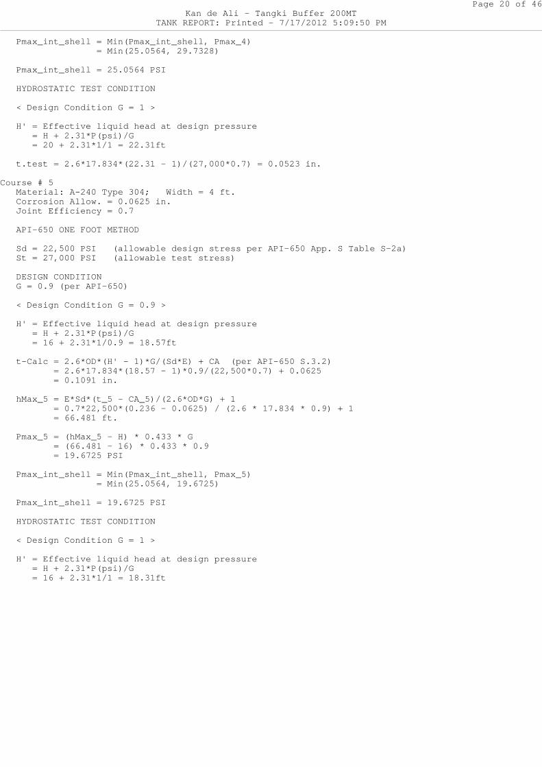
Pmax_int_shell = Min(Pmax_int_shell, Pmax_4) = Min(25.0564, 29.7328)
Pmax_int_shell = 25.0564 PSI
HYDROSTATIC TEST CONDITION
< Design Condition G = 1 >
H' = Effective liquid head at design pressure = H + 2.31*P(psi)/G = 20 + 2.31*1/1 = 22.31ft
t.test = 2.6*17.834*(22.31 - 1)/(27,000*0.7) = 0 .0523 in.
Course # 5 Material: A-240 Type 304; Width = 4 ft.
Corrosion Allow. = 0.0625 in. Joint Efficiency = 0.7
API-650 ONE FOOT METHOD
Sd = 22,500 PSI (allowable design stress per A PI-650 App. S Table S-2a) St = 27,000 PSI (allowable test stress)
DESIGN CONDITION G = 0.9 (per API-650)
< Design Condition G = 0.9 >
H' = Effective liquid head at design pressure = H + 2.31*P(psi)/G = 16 + 2.31*1/0.9 = 18.57ft
t-Calc = 2.6*OD*(H' - 1)*G/(Sd*E) + CA (per API -650 S.3.2) = 2.6*17.834*(18.57 - 1)*0.9/(22,500*0.7) + 0.0625 = 0.1091 in.
hMax_5 = E*Sd*(t_5 - CA_5)/(2.6*OD*G) + 1 = 0.7*22,500*(0.236 - 0.0625) / (2.6 * 17 .834 * 0.9) + 1 = 66.481 ft.
Pmax_5 = (hMax_5 - H) * 0.433 * G = (66.481 - 16) * 0.433 * 0.9 = 19.6725 PSI
Pmax_int_shell = Min(Pmax_int_shell, Pmax_5) = Min(25.0564, 19.6725)
Pmax_int_shell = 19.6725 PSI
HYDROSTATIC TEST CONDITION
< Design Condition G = 1 >
H' = Effective liquid head at design pressure = H + 2.31*P(psi)/G = 16 + 2.31*1/1 = 18.31ft
Page 21 of 46Kan de Ali - Tangki Buffer 200MT
TANK REPORT: Printed - 7/17/2012 5:09:50 PM
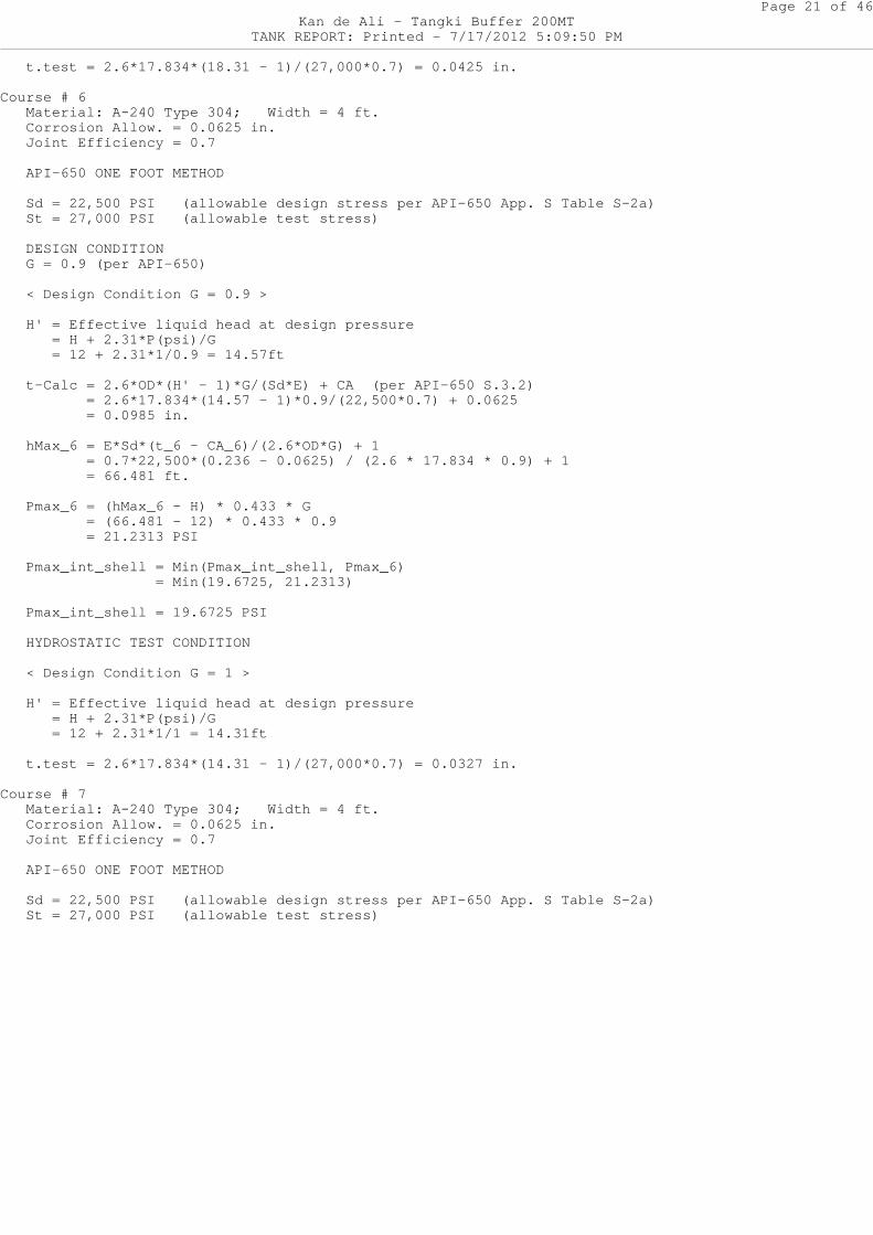
t.test = 2.6*17.834*(18.31 - 1)/(27,000*0.7) = 0 .0425 in.
Course # 6 Material: A-240 Type 304; Width = 4 ft.
Corrosion Allow. = 0.0625 in. Joint Efficiency = 0.7
API-650 ONE FOOT METHOD
Sd = 22,500 PSI (allowable design stress per A PI-650 App. S Table S-2a) St = 27,000 PSI (allowable test stress)
DESIGN CONDITION G = 0.9 (per API-650)
< Design Condition G = 0.9 >
H' = Effective liquid head at design pressure = H + 2.31*P(psi)/G = 12 + 2.31*1/0.9 = 14.57ft
t-Calc = 2.6*OD*(H' - 1)*G/(Sd*E) + CA (per API -650 S.3.2) = 2.6*17.834*(14.57 - 1)*0.9/(22,500*0.7) + 0.0625 = 0.0985 in.
hMax_6 = E*Sd*(t_6 - CA_6)/(2.6*OD*G) + 1 = 0.7*22,500*(0.236 - 0.0625) / (2.6 * 17 .834 * 0.9) + 1 = 66.481 ft.
Pmax_6 = (hMax_6 - H) * 0.433 * G = (66.481 - 12) * 0.433 * 0.9 = 21.2313 PSI
Pmax_int_shell = Min(Pmax_int_shell, Pmax_6) = Min(19.6725, 21.2313)
Pmax_int_shell = 19.6725 PSI
HYDROSTATIC TEST CONDITION
< Design Condition G = 1 >
H' = Effective liquid head at design pressure = H + 2.31*P(psi)/G = 12 + 2.31*1/1 = 14.31ft
t.test = 2.6*17.834*(14.31 - 1)/(27,000*0.7) = 0 .0327 in.
Course # 7 Material: A-240 Type 304; Width = 4 ft.
Corrosion Allow. = 0.0625 in. Joint Efficiency = 0.7
API-650 ONE FOOT METHOD
Sd = 22,500 PSI (allowable design stress per A PI-650 App. S Table S-2a) St = 27,000 PSI (allowable test stress)
Page 22 of 46Kan de Ali - Tangki Buffer 200MT
TANK REPORT: Printed - 7/17/2012 5:09:50 PM
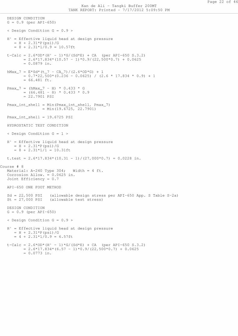
DESIGN CONDITION G = 0.9 (per API-650)
< Design Condition G = 0.9 >
H' = Effective liquid head at design pressure = H + 2.31*P(psi)/G = 8 + 2.31*1/0.9 = 10.57ft
t-Calc = 2.6*OD*(H' - 1)*G/(Sd*E) + CA (per API -650 S.3.2) = 2.6*17.834*(10.57 - 1)*0.9/(22,500*0.7) + 0.0625 = 0.0879 in.
hMax_7 = E*Sd*(t_7 - CA_7)/(2.6*OD*G) + 1 = 0.7*22,500*(0.236 - 0.0625) / (2.6 * 17 .834 * 0.9) + 1 = 66.481 ft.
Pmax_7 = (hMax_7 - H) * 0.433 * G = (66.481 - 8) * 0.433 * 0.9 = 22.7901 PSI
Pmax_int_shell = Min(Pmax_int_shell, Pmax_7) = Min(19.6725, 22.7901)
Pmax_int_shell = 19.6725 PSI
HYDROSTATIC TEST CONDITION
< Design Condition G = 1 >
H' = Effective liquid head at design pressure = H + 2.31*P(psi)/G = 8 + 2.31*1/1 = 10.31ft
t.test = 2.6*17.834*(10.31 - 1)/(27,000*0.7) = 0 .0228 in.
Course # 8 Material: A-240 Type 304; Width = 4 ft.
Corrosion Allow. = 0.0625 in. Joint Efficiency = 0.7
API-650 ONE FOOT METHOD
Sd = 22,500 PSI (allowable design stress per A PI-650 App. S Table S-2a) St = 27,000 PSI (allowable test stress)
DESIGN CONDITION G = 0.9 (per API-650)
< Design Condition G = 0.9 >
H' = Effective liquid head at design pressure = H + 2.31*P(psi)/G = 4 + 2.31*1/0.9 = 6.57ft
t-Calc = 2.6*OD*(H' - 1)*G/(Sd*E) + CA (per API -650 S.3.2) = 2.6*17.834*(6.57 - 1)*0.9/(22,500*0.7) + 0.0625 = 0.0773 in.
Page 23 of 46Kan de Ali - Tangki Buffer 200MT
TANK REPORT: Printed - 7/17/2012 5:09:50 PM
hMax_8 = E*Sd*(t_8 - CA_8)/(2.6*OD*G) + 1 = 0.7*22,500*(0.236 - 0.0625) / (2.6 * 17 .834 * 0.9) + 1 = 66.481 ft.
Pmax_8 = (hMax_8 - H) * 0.433 * G = (66.481 - 4) * 0.433 * 0.9 = 24.3489 PSI
Pmax_int_shell = Min(Pmax_int_shell, Pmax_8) = Min(19.6725, 24.3489)
Pmax_int_shell = 19.6725 PSI
HYDROSTATIC TEST CONDITION
< Design Condition G = 1 >
H' = Effective liquid head at design pressure = H + 2.31*P(psi)/G = 4 + 2.31*1/1 = 6.31ft
t.test = 2.6*17.834*(6.31 - 1)/(27,000*0.7) = 0. 013 in.
Wtr = Transposed Width of each Shell Course = Width*[ t_top / t_course ]^2.5
Transforming Courses (1) to (8)
Wtr(1) = 4*[ 0.236/0.315 ]^2.5 = 1.9434 ft Wtr(2) = 4*[ 0.236/0.315 ]^2.5 = 1.9434 ft Wtr(3) = 4*[ 0.236/0.315 ]^2.5 = 1.9434 ft Wtr(4) = 4*[ 0.236/0.315 ]^2.5 = 1.9434 ft Wtr(5) = 4*[ 0.236/0.236 ]^2.5 = 4 ft Wtr(6) = 4*[ 0.236/0.236 ]^2.5 = 4 ft Wtr(7) = 4*[ 0.236/0.236 ]^2.5 = 4 ft Wtr(8) = 4*[ 0.236/0.236 ]^2.5 = 4 ft Hts (Height of the Transformed Shell) = SUM{Wtr} = 23.7736 ft
INTERMEDIATE WIND GIRDERS (API 650 Section 5.9.7 ) V (Wind Speed) = 20 mph Ve = vf = Velocity Factor = (vs/120)^2 = (20/120 )^2 = 0.0278 Design PV = 0 PSI, OR 0 In. H2O
<TOP END STIFFENER CALCULATIONS> Z = Required Top Comp Ring Section Modulus (per API-650 5.1.5.9.e) = 0.27 in^3,
For Structural Roof and OD <= 35 ft, Minimum Required Angle is 2 x 2 x 3/16 in. Actual Z = 0.863 in^3 Using L3x2x3/8, Wc = 3.0158
<INTERMEDIATE STIFFENER CALCULATIONS> (PER API-650 Section 5.9.7)
* * * NOTE: Using the thinnest shell course, t_thi nnest, instead of top shell course.
Page 24 of 46Kan de Ali - Tangki Buffer 200MT
TANK REPORT: Printed - 7/17/2012 5:09:50 PM
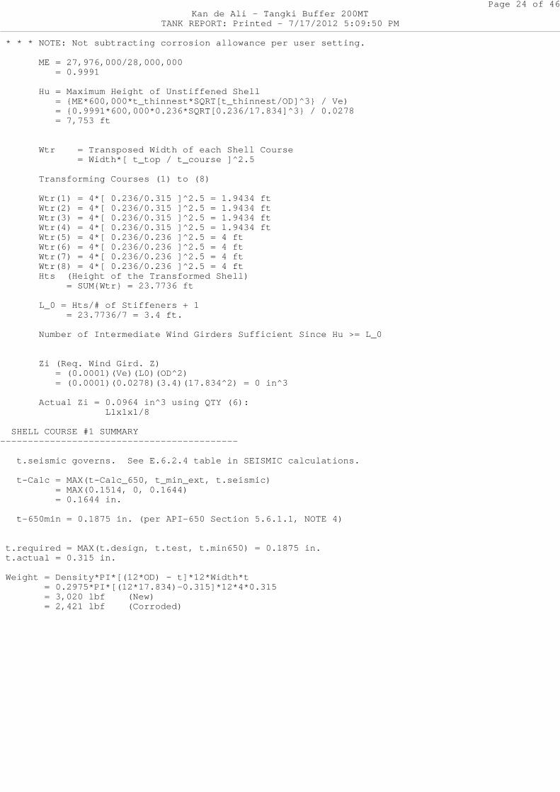
* * * NOTE: Not subtracting corrosion allowance pe r user setting.
ME = 27,976,000/28,000,000 = 0.9991
Hu = Maximum Height of Unstiffened Shell = {ME*600,000*t_thinnest*SQRT[t_thinnest/ OD]^3} / Ve) = {0.9991*600,000*0.236*SQRT[0.236/17.834 ]^3} / 0.0278 = 7,753 ft
Wtr = Transposed Width of each Shell Cour se = Width*[ t_top / t_course ]^2.5
Transforming Courses (1) to (8)
Wtr(1) = 4*[ 0.236/0.315 ]^2.5 = 1.9434 ft Wtr(2) = 4*[ 0.236/0.315 ]^2.5 = 1.9434 ft Wtr(3) = 4*[ 0.236/0.315 ]^2.5 = 1.9434 ft Wtr(4) = 4*[ 0.236/0.315 ]^2.5 = 1.9434 ft Wtr(5) = 4*[ 0.236/0.236 ]^2.5 = 4 ft Wtr(6) = 4*[ 0.236/0.236 ]^2.5 = 4 ft Wtr(7) = 4*[ 0.236/0.236 ]^2.5 = 4 ft Wtr(8) = 4*[ 0.236/0.236 ]^2.5 = 4 ft Hts (Height of the Transformed Shell) = SUM{Wtr} = 23.7736 ft
L_0 = Hts/# of Stiffeners + 1 = 23.7736/7 = 3.4 ft.
Number of Intermediate Wind Girders Sufficie nt Since Hu >= L_0
Zi (Req. Wind Gird. Z) = (0.0001)(Ve)(L0)(OD^2) = (0.0001)(0.0278)(3.4)(17.834^2) = 0 in^ 3
Actual Zi = 0.0964 in^3 using QTY (6): L1x1x1/8
SHELL COURSE #1 SUMMARY-------------------------------------------
t.seismic governs. See E.6.2.4 table in SEISMIC calculations.
t-Calc = MAX(t-Calc_650, t_min_ext, t.seismic) = MAX(0.1514, 0, 0.1644) = 0.1644 in.
t-650min = 0.1875 in. (per API-650 Section 5.6.1 .1, NOTE 4)
t.required = MAX(t.design, t.test, t.min650) = 0.1 875 in. t.actual = 0.315 in.
Weight = Density*PI*[(12*OD) - t]*12*Width*t = 0.2975*PI*[(12*17.834)-0.315]*12*4*0.315 = 3,020 lbf (New) = 2,421 lbf (Corroded)
Page 25 of 46Kan de Ali - Tangki Buffer 200MT
TANK REPORT: Printed - 7/17/2012 5:09:50 PM
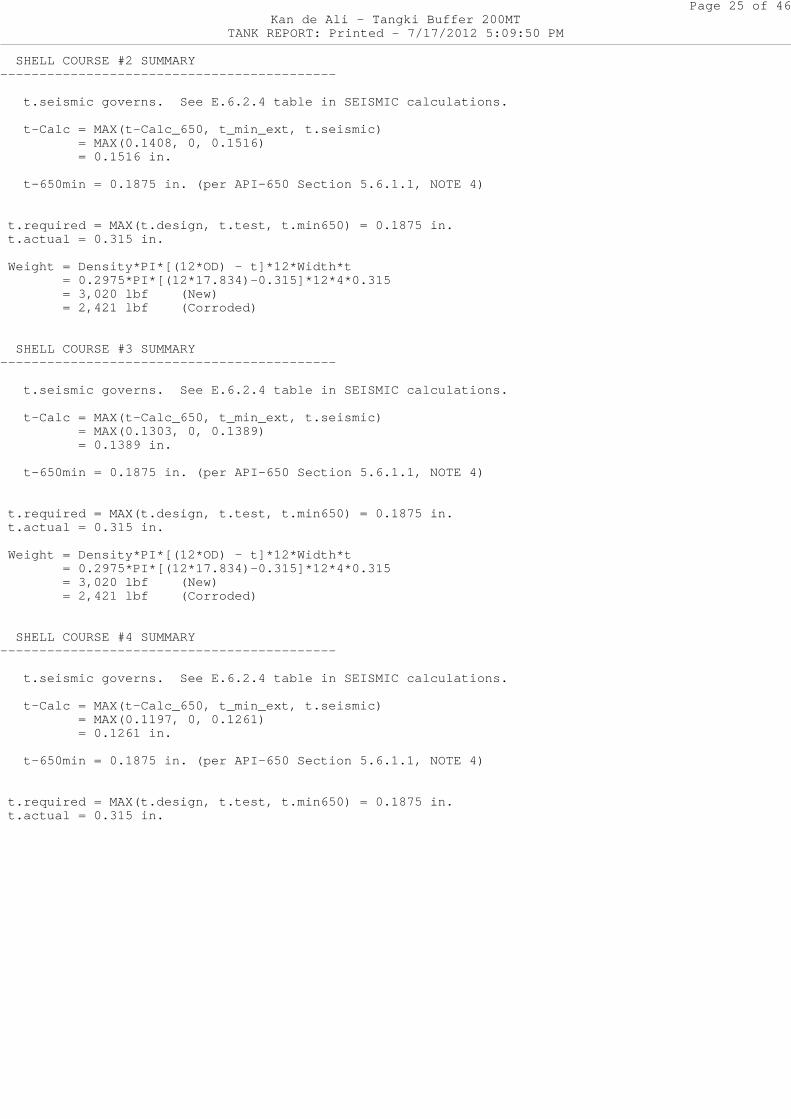
SHELL COURSE #2 SUMMARY-------------------------------------------
t.seismic governs. See E.6.2.4 table in SEISMIC calculations.
t-Calc = MAX(t-Calc_650, t_min_ext, t.seismic) = MAX(0.1408, 0, 0.1516) = 0.1516 in.
t-650min = 0.1875 in. (per API-650 Section 5.6.1 .1, NOTE 4)
t.required = MAX(t.design, t.test, t.min650) = 0.1 875 in. t.actual = 0.315 in.
Weight = Density*PI*[(12*OD) - t]*12*Width*t = 0.2975*PI*[(12*17.834)-0.315]*12*4*0.315 = 3,020 lbf (New) = 2,421 lbf (Corroded)
SHELL COURSE #3 SUMMARY-------------------------------------------
t.seismic governs. See E.6.2.4 table in SEISMIC calculations.
t-Calc = MAX(t-Calc_650, t_min_ext, t.seismic) = MAX(0.1303, 0, 0.1389) = 0.1389 in.
t-650min = 0.1875 in. (per API-650 Section 5.6.1 .1, NOTE 4)
t.required = MAX(t.design, t.test, t.min650) = 0.1 875 in. t.actual = 0.315 in.
Weight = Density*PI*[(12*OD) - t]*12*Width*t = 0.2975*PI*[(12*17.834)-0.315]*12*4*0.315 = 3,020 lbf (New) = 2,421 lbf (Corroded)
SHELL COURSE #4 SUMMARY-------------------------------------------
t.seismic governs. See E.6.2.4 table in SEISMIC calculations.
t-Calc = MAX(t-Calc_650, t_min_ext, t.seismic) = MAX(0.1197, 0, 0.1261) = 0.1261 in.
t-650min = 0.1875 in. (per API-650 Section 5.6.1 .1, NOTE 4)
t.required = MAX(t.design, t.test, t.min650) = 0.1 875 in. t.actual = 0.315 in.
Page 26 of 46Kan de Ali - Tangki Buffer 200MT
TANK REPORT: Printed - 7/17/2012 5:09:50 PM
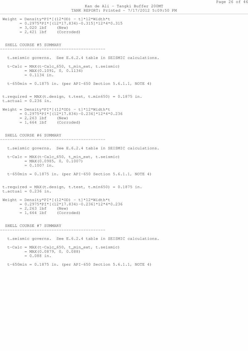
Weight = Density*PI*[(12*OD) - t]*12*Width*t = 0.2975*PI*[(12*17.834)-0.315]*12*4*0.315 = 3,020 lbf (New) = 2,421 lbf (Corroded)
SHELL COURSE #5 SUMMARY-------------------------------------------
t.seismic governs. See E.6.2.4 table in SEISMIC calculations.
t-Calc = MAX(t-Calc_650, t_min_ext, t.seismic) = MAX(0.1091, 0, 0.1134) = 0.1134 in.
t-650min = 0.1875 in. (per API-650 Section 5.6.1 .1, NOTE 4)
t.required = MAX(t.design, t.test, t.min650) = 0.1 875 in. t.actual = 0.236 in.
Weight = Density*PI*[(12*OD) - t]*12*Width*t = 0.2975*PI*[(12*17.834)-0.236]*12*4*0.236 = 2,263 lbf (New) = 1,664 lbf (Corroded)
SHELL COURSE #6 SUMMARY-------------------------------------------
t.seismic governs. See E.6.2.4 table in SEISMIC calculations.
t-Calc = MAX(t-Calc_650, t_min_ext, t.seismic) = MAX(0.0985, 0, 0.1007) = 0.1007 in.
t-650min = 0.1875 in. (per API-650 Section 5.6.1 .1, NOTE 4)
t.required = MAX(t.design, t.test, t.min650) = 0.1 875 in. t.actual = 0.236 in.
Weight = Density*PI*[(12*OD) - t]*12*Width*t = 0.2975*PI*[(12*17.834)-0.236]*12*4*0.236 = 2,263 lbf (New) = 1,664 lbf (Corroded)
SHELL COURSE #7 SUMMARY-------------------------------------------
t.seismic governs. See E.6.2.4 table in SEISMIC calculations.
t-Calc = MAX(t-Calc_650, t_min_ext, t.seismic) = MAX(0.0879, 0, 0.088) = 0.088 in.
t-650min = 0.1875 in. (per API-650 Section 5.6.1 .1, NOTE 4)
Page 27 of 46Kan de Ali - Tangki Buffer 200MT
TANK REPORT: Printed - 7/17/2012 5:09:50 PM
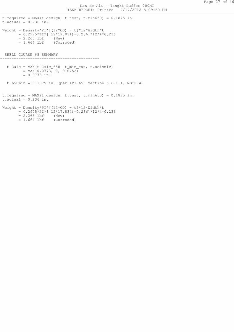
t.required = MAX(t.design, t.test, t.min650) = 0.1 875 in. t.actual = 0.236 in.
Weight = Density*PI*[(12*OD) - t]*12*Width*t = 0.2975*PI*[(12*17.834)-0.236]*12*4*0.236 = 2,263 lbf (New) = 1,664 lbf (Corroded)
SHELL COURSE #8 SUMMARY-------------------------------------------
t-Calc = MAX(t-Calc_650, t_min_ext, t.seismic) = MAX(0.0773, 0, 0.0752) = 0.0773 in.
t-650min = 0.1875 in. (per API-650 Section 5.6.1 .1, NOTE 4)
t.required = MAX(t.design, t.test, t.min650) = 0.1 875 in. t.actual = 0.236 in.
Weight = Density*PI*[(12*OD) - t]*12*Width*t = 0.2975*PI*[(12*17.834)-0.236]*12*4*0.236 = 2,263 lbf (New) = 1,664 lbf (Corroded)
Page 28 of 46Kan de Ali - Tangki Buffer 200MT
TANK REPORT: Printed - 7/17/2012 5:09:50 PM
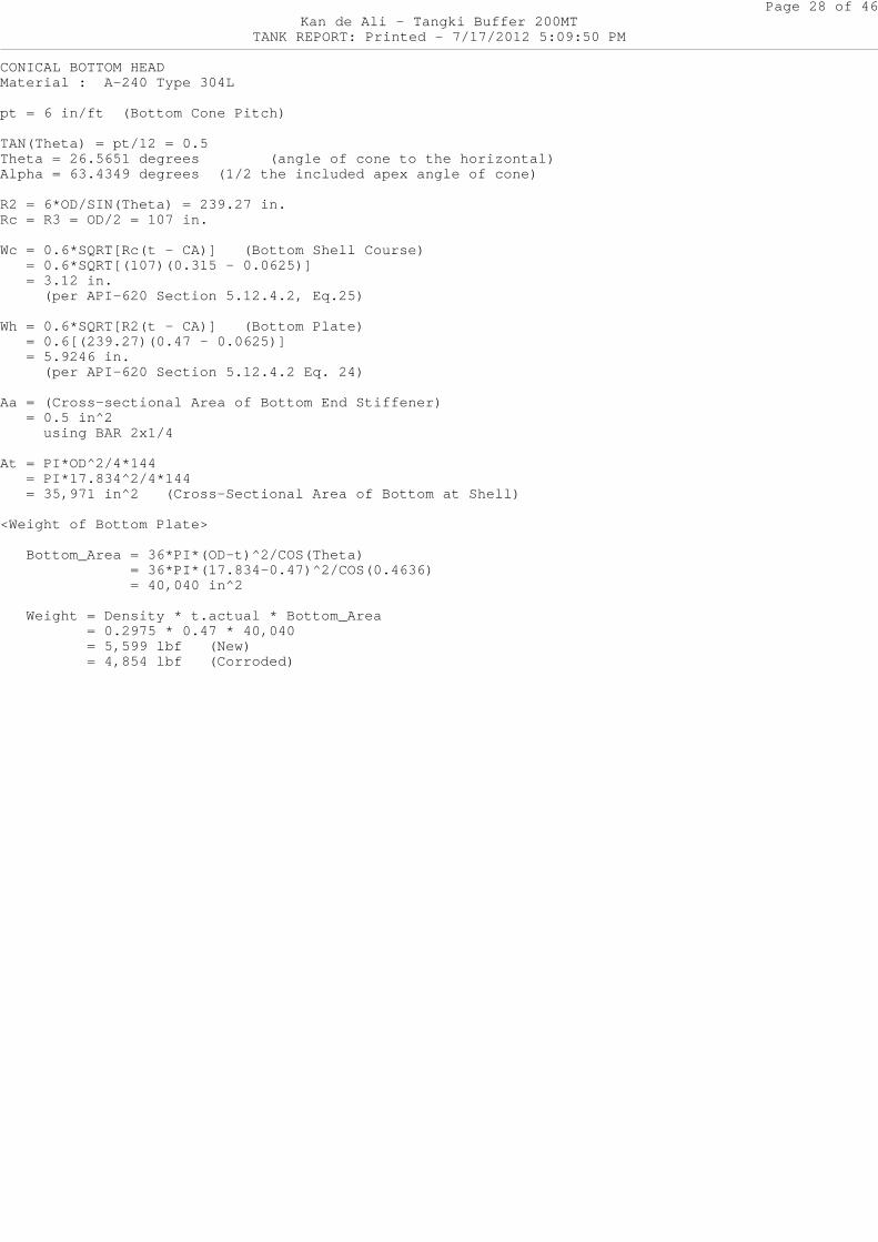
CONICAL BOTTOM HEADMaterial : A-240 Type 304L
pt = 6 in/ft (Bottom Cone Pitch)
TAN(Theta) = pt/12 = 0.5Theta = 26.5651 degrees (angle of cone to th e horizontal)Alpha = 63.4349 degrees (1/2 the included apex ang le of cone)
R2 = 6*OD/SIN(Theta) = 239.27 in.Rc = R3 = OD/2 = 107 in.
Wc = 0.6*SQRT[Rc(t - CA)] (Bottom Shell Course) = 0.6*SQRT[(107)(0.315 - 0.0625)] = 3.12 in. (per API-620 Section 5.12.4.2, Eq.25)
Wh = 0.6*SQRT[R2(t - CA)] (Bottom Plate) = 0.6[(239.27)(0.47 - 0.0625)] = 5.9246 in. (per API-620 Section 5.12.4.2 Eq. 24)
Aa = (Cross-sectional Area of Bottom End Stiffener) = 0.5 in^2 using BAR 2x1/4
At = PI*OD^2/4*144 = PI*17.834^2/4*144 = 35,971 in^2 (Cross-Sectional Area of Bottom at Shell)
<Weight of Bottom Plate>
Bottom_Area = 36*PI*(OD-t)^2/COS(Theta) = 36*PI*(17.834-0.47)^2/COS(0.4636) = 40,040 in^2
Weight = Density * t.actual * Bottom_Area = 0.2975 * 0.47 * 40,040 = 5,599 lbf (New) = 4,854 lbf (Corroded)
Page 29 of 46Kan de Ali - Tangki Buffer 200MT
TANK REPORT: Printed - 7/17/2012 5:09:50 PM
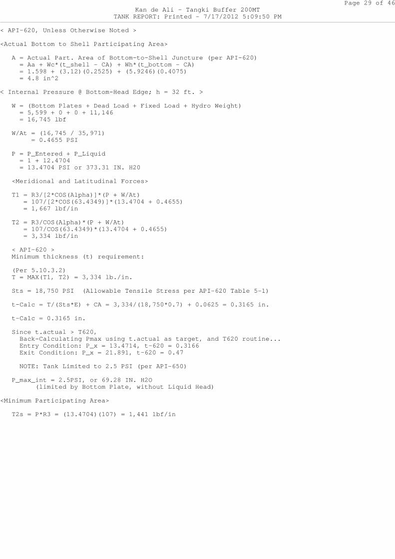
< API-620, Unless Otherwise Noted >
<Actual Bottom to Shell Participating Area>
A = Actual Part. Area of Bottom-to-Shell Junctur e (per API-620) = Aa + Wc*(t_shell - CA) + Wh*(t_bottom - CA) = 1.598 + (3.12)(0.2525) + (5.9246)(0.4075) = 4.8 in^2
< Internal Pressure @ Bottom-Head Edge; h = 32 ft. >
W = (Bottom Plates + Dead Load + Fixed Load + Hy dro Weight) = 5,599 + 0 + 0 + 11,146 = 16,745 lbf
W/At = (16,745 / 35,971) = 0.4655 PSI
P = P_Entered + P_Liquid = 1 + 12.4704 = 13.4704 PSI or 373.31 IN. H20
<Meridional and Latitudinal Forces>
T1 = R3/[2*COS(Alpha)]*(P + W/At) = 107/[2*COS(63.4349)]*(13.4704 + 0.4655) = 1,667 lbf/in
T2 = R3/COS(Alpha)*(P + W/At) = 107/COS(63.4349)*(13.4704 + 0.4655) = 3,334 lbf/in
< API-620 > Minimum thickness (t) requirement:
(Per 5.10.3.2) T = MAX(T1, T2) = 3,334 lb./in.
Sts = 18,750 PSI (Allowable Tensile Stress per API-620 Table 5-1)
t-Calc = T/(Sts*E) + CA = 3,334/(18,750*0.7) + 0 .0625 = 0.3165 in.
t-Calc = 0.3165 in.
Since t.actual > T620, Back-Calculating Pmax using t.actual as target , and T620 routine... Entry Condition: P_x = 13.4714, t-620 = 0.3166 Exit Condition: P_x = 21.891, t-620 = 0.47
NOTE: Tank Limited to 2.5 PSI (per API-650)
P_max_int = 2.5PSI, or 69.28 IN. H2O (limited by Bottom Plate, without Liquid H ead)
<Minimum Participating Area>
T2s = P*R3 = (13.4704)(107) = 1,441 lbf/in
Page 30 of 46Kan de Ali - Tangki Buffer 200MT
TANK REPORT: Printed - 7/17/2012 5:09:50 PM
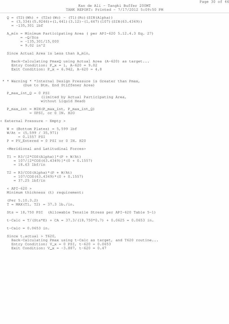
Q = (T2)(Wh) + (T2s)(Wc) - (T1)(Rc)(SIN(Alpha)) = (3,334)(5.9246)+(1,441)(3.12)-(1,667)(107)(S IN(63.4349)) = -135,301 lbf
A_min = Minimum Participating Area ( per API-620 5.12.4.3 Eq. 27) = -Q/Scs = -135,301/15,000 = 9.02 in^2
Since Actual Area is Less than A_min,
Back-Calculating PmaxQ using Actual Area (A-62 0) as target... Entry Condition: P_x = 1, A-620 = 9.02 Exit Condition: P_x = 6.942, A-620 = 4.8
* * Warning * *Internal Design Pressure is Greater than Pmax, (Due to Btm. End Stiffener Area)
P_max_int_Q = 0 PSI (limited by Actual Participating Area, without Liquid Head)
P_max_int = MIN(P_max_int, P_max_int_Q) = 0PSI, or 0 IN. H2O
< External Pressure - Empty >
W = (Bottom Plates) = 5,599 lbf W/At = (5,599 / 35,971) = 0.1557 PSI P = PV_Entered = 0 PSI or 0 IN. H20
<Meridional and Latitudinal Forces>
T1 = R3/[2*COS(Alpha)]*(P + W/At) = 107/[2*COS(63.4349)]*(0 + 0.1557) = 18.63 lbf/in
T2 = R3/COS(Alpha)*(P + W/At) = 107/COS(63.4349)*(0 + 0.1557) = 37.25 lbf/in
< API-620 > Minimum thickness (t) requirement:
(Per 5.10.3.2) T = MAX(T1, T2) = 37.3 lb./in.
Sts = 18,750 PSI (Allowable Tensile Stress per API-620 Table 5-1)
t-Calc = T/(Sts*E) + CA = 37.3/(18,750*0.7) + 0. 0625 = 0.0653 in.
t-Calc = 0.0653 in.
Since t.actual > T620, Back-Calculating Pmax using t-Calc as target, and T620 routine... Entry Condition: V_x = 0 PSI, t-620 = 0.0653 Exit Condition: V_x = -3.887, t-620 = 0.47
Page 31 of 46Kan de Ali - Tangki Buffer 200MT
TANK REPORT: Printed - 7/17/2012 5:09:50 PM
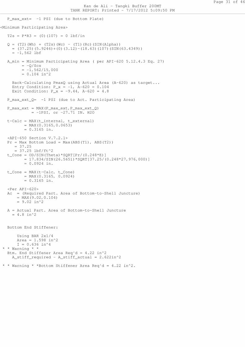
P_max_ext= -1 PSI (due to Bottom Plate)
<Minimum Participating Area>
T2s = P*R3 = (0)(107) = 0 lbf/in
Q = (T2)(Wh) + (T2s)(Wc) - (T1)(Rc)(SIN(Alpha)) = (37.25)(5.9246)+(0)(3.12)-(18.63)(107)(SIN(6 3.4349)) = -1,562 lbf
A_min = Minimum Participating Area ( per API-620 5.12.4.3 Eq. 27) = -Q/Scs = -1,562/15,000 = 0.104 in^2
Back-Calculating PmaxQ using Actual Area (A-62 0) as target... Entry Condition: P_x = -1, A-620 = 0.104 Exit Condition: P_x = -9.44, A-620 = 4.8
P_max_ext_Q= -1 PSI (due to Act. Participating Area)
P_max_ext = MAX(P_max_ext,P_max_ext_Q) = -1PSI, or -27.71 IN. H2O
t-Calc = MAX(t_internal, t_external) = MAX(0.3165,0.0653) = 0.3165 in.
<API-650 Section V.7.2.1> Pr = Max Bottom Load = Max(ABS(T1), ABS(T2)) = 37.25 = 37.25 lbf/ft^2 t_Cone = OD/SIN(Theta)*SQRT[Pr/(0.248*E)] = 17.834/SIN(26.5651)*SQRT[37.25/(0.248*2 7,976,000)] = 0.0924 in.
t_Cone = MAX(t-Calc, t_Cone) = MAX(0.3165, 0.0924) = 0.3165 in.
<Per API-620> Ac = (Required Part. Area of Bottom-to-Shell Ju ncture) = MAX(9.02,0.104) = 9.02 in^2
A = Actual Part. Area of Bottom-to-Shell Junctur e = 4.8 in^2
Bottom End Stiffener:
Using BAR 2x1/4 Area = 1.598 in^2 I = 0.636 in^4 * * Warning * * Btm. End Stiffener Area Req'd = 4.22 in^2 A_stiff_required - A_stiff_actual = 2.622in^2
* * Warning * *Bottom Stiffener Area Req'd = 4.22 in^2.
Page 32 of 46Kan de Ali - Tangki Buffer 200MT
TANK REPORT: Printed - 7/17/2012 5:09:50 PM
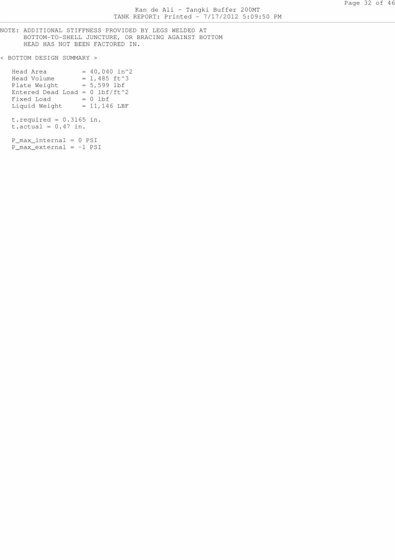
NOTE: ADDITIONAL STIFFNESS PROVIDED BY LEGS WELDED AT BOTTOM-TO-SHELL JUNCTURE, OR BRACING AGAINST BOTTOM HEAD HAS NOT BEEN FACTORED IN.
< BOTTOM DESIGN SUMMARY >
Head Area = 40,040 in^2 Head Volume = 1,485 ft^3 Plate Weight = 5,599 lbf Entered Dead Load = 0 lbf/ft^2 Fixed Load = 0 lbf Liquid Weight = 11,146 LBF
t.required = 0.3165 in. t.actual = 0.47 in.
P_max_internal = 0 PSI P_max_external = -1 PSI
Page 33 of 46Kan de Ali - Tangki Buffer 200MT
TANK REPORT: Printed - 7/17/2012 5:09:50 PM
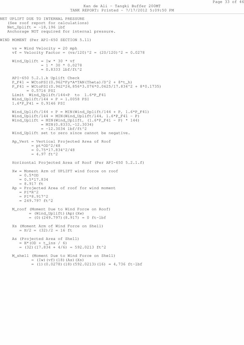
NET UPLIFT DUE TO INTERNAL PRESSURE (See roof report for calculations) Net_Uplift = -18,196 lbf Anchorage NOT required for internal pressure.
WIND MOMENT (Per API-650 SECTION 5.11)
vs = Wind Velocity = 20 mph vf = Velocity Factor = (vs/120)^2 = (20/120)^2 = 0.0278
Wind_Uplift = Iw * 30 * vf = 1 * 30 * 0.0278 = 0.8333 lbf/ft^2
API-650 5.2.1.k Uplift Check P_F41 = WCtoPSI(0.962*Fy*A*TAN(Theta)/D^2 + 8* t_h) P_F41 = WCtoPSI(0.962*24,856*3.076*0.0625/17.8 34^2 + 8*0.1735) = 0.5716 PSI Limit Wind_Uplift/144+P to 1.6*P_F41 Wind_Uplift/144 + P = 1.0058 PSI 1.6*P_F41 = 0.9146 PSI
Wind_Uplift/144 + P = MIN(Wind_Uplift/144 + P, 1.6*P_F41) Wind_Uplift/144 = MIN(Wind_Uplift/144, 1.6*P_F 41 - P) Wind_Uplift = MIN(Wind_Uplift, (1.6*P_F41 - P) * 144) = MIN(0.8333,-12.3034) = -12.3034 lbf/ft^2 Wind_Uplift set to zero since cannot be negati ve.
Ap_Vert = Vertical Projected Area of Roof = pt*OD^2/48 = 0.75*17.834^2/48 = 4.97 ft^2
Horizontal Projected Area of Roof (Per API-650 5.2.1.f)
Xw = Moment Arm of UPLIFT wind force on roof = 0.5*OD = 0.5*17.834 = 8.917 ft Ap = Projected Area of roof for wind moment = PI*R^2 = PI*8.917^2 = 249.797 ft^2
M_roof (Moment Due to Wind Force on Roof) = (Wind_Uplift)(Ap)(Xw) = (0)(249.797)(8.917) = 0 ft-lbf
Xs (Moment Arm of Wind Force on Shell) = H/2 = (32)/2 = 16 ft
As (Projected Area of Shell) = H*(OD + t_ins / 6) = (32)(17.834 + 4/6) = 592.0213 ft^2
M_shell (Moment Due to Wind Force on Shell) = (Iw)(vf)(18)(As)(Xs) = (1)(0.0278)(18)(592.0213)(16) = 4,73 6 ft-lbf
Page 34 of 46Kan de Ali - Tangki Buffer 200MT
TANK REPORT: Printed - 7/17/2012 5:09:50 PM
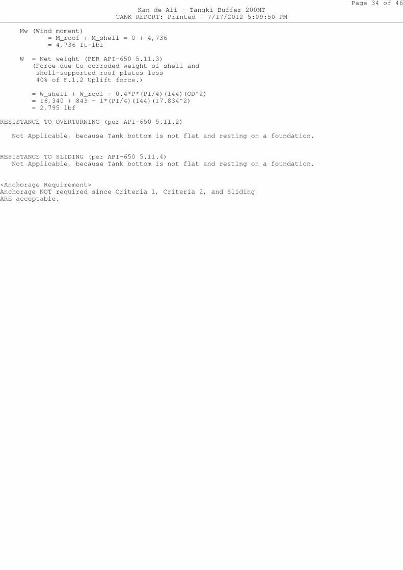
Mw (Wind moment) = M_roof + M_shell = 0 + 4,736 = 4,736 ft-lbf
W = Net weight (PER API-650 5.11.3) (Force due to corroded weight of shell and shell-supported roof plates less 40% of F.1.2 Uplift force.)
= W_shell + W_roof - 0.4*P*(PI/4)(144)(OD^2 ) = 16,340 + 843 - 1*(PI/4)(144)(17.834^2) = 2,795 lbf
RESISTANCE TO OVERTURNING (per API-650 5.11.2)
Not Applicable, because Tank bottom is not flat and resting on a foundation.
RESISTANCE TO SLIDING (per API-650 5.11.4) Not Applicable, because Tank bottom is not flat and resting on a foundation.
<Anchorage Requirement>Anchorage NOT required since Criteria 1, Criteria 2 , and SlidingARE acceptable.
Page 35 of 46Kan de Ali - Tangki Buffer 200MT
TANK REPORT: Printed - 7/17/2012 5:09:50 PM
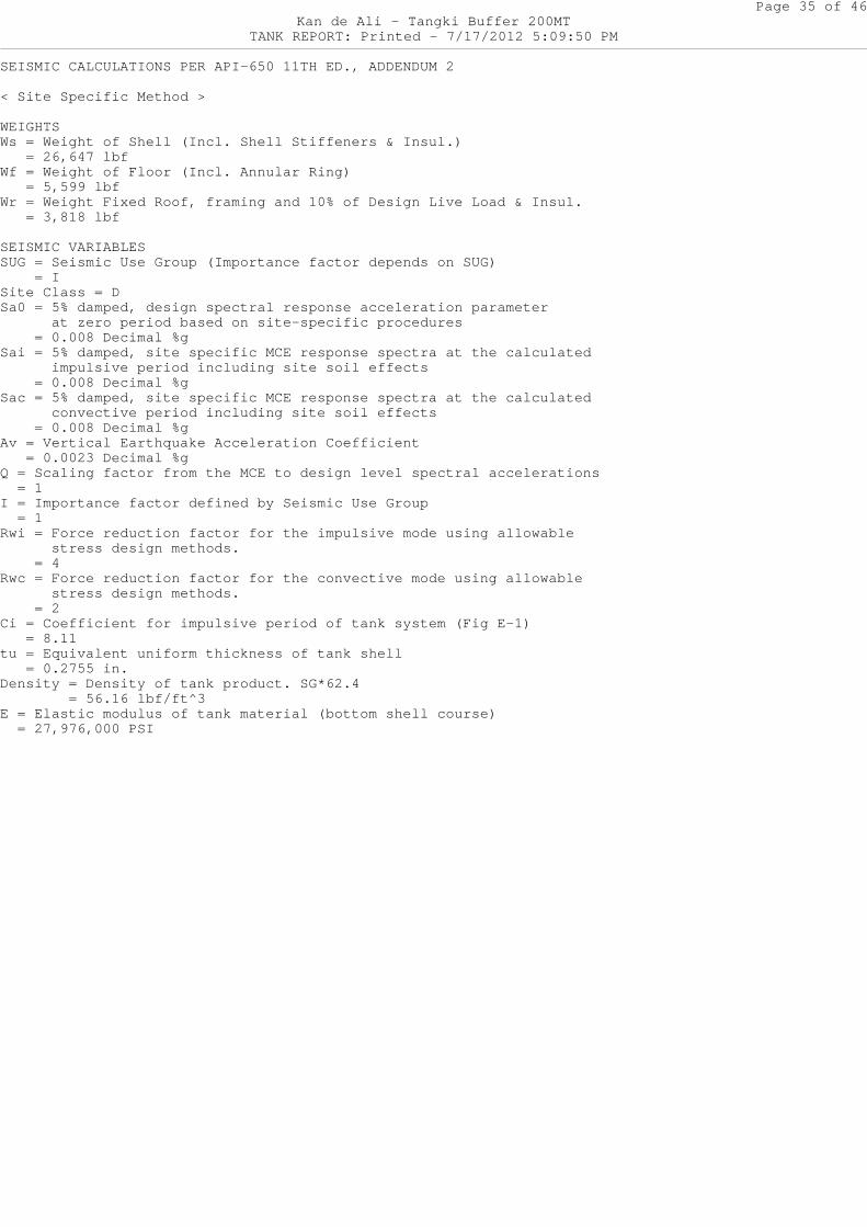
SEISMIC CALCULATIONS PER API-650 11TH ED., ADDENDUM 2
< Site Specific Method >
WEIGHTSWs = Weight of Shell (Incl. Shell Stiffeners & Insu l.) = 26,647 lbfWf = Weight of Floor (Incl. Annular Ring) = 5,599 lbfWr = Weight Fixed Roof, framing and 10% of Design L ive Load & Insul. = 3,818 lbf
SEISMIC VARIABLESSUG = Seismic Use Group (Importance factor depends on SUG) = ISite Class = DSa0 = 5% damped, design spectral response accelerat ion parameter at zero period based on site-specific procedu res = 0.008 Decimal %gSai = 5% damped, site specific MCE response spectra at the calculated impulsive period including site soil effects = 0.008 Decimal %gSac = 5% damped, site specific MCE response spectra at the calculated convective period including site soil effects = 0.008 Decimal %gAv = Vertical Earthquake Acceleration Coefficient = 0.0023 Decimal %gQ = Scaling factor from the MCE to design level spe ctral accelerations = 1I = Importance factor defined by Seismic Use Group = 1Rwi = Force reduction factor for the impulsive mode using allowable stress design methods. = 4Rwc = Force reduction factor for the convective mod e using allowable stress design methods. = 2Ci = Coefficient for impulsive period of tank syste m (Fig E-1) = 8.11tu = Equivalent uniform thickness of tank shell = 0.2755 in.Density = Density of tank product. SG*62.4 = 56.16 lbf/ft^3E = Elastic modulus of tank material (bottom shell course) = 27,976,000 PSI
Page 36 of 46Kan de Ali - Tangki Buffer 200MT
TANK REPORT: Printed - 7/17/2012 5:09:51 PM
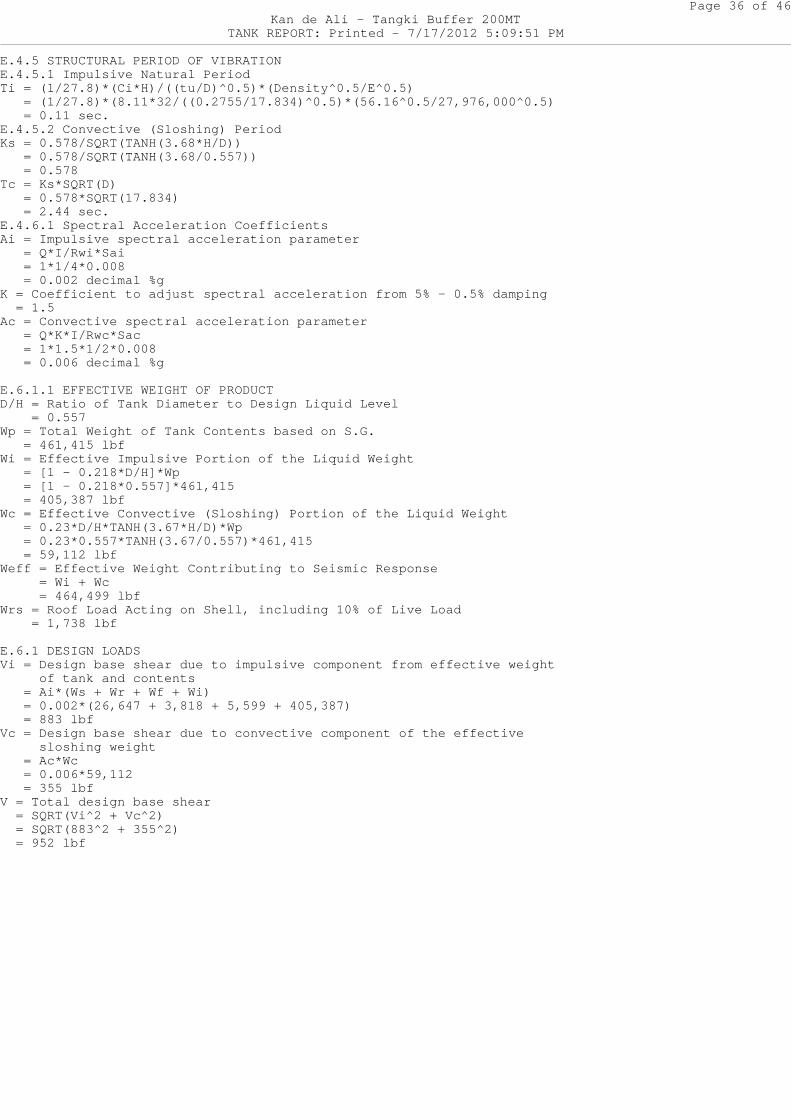
E.4.5 STRUCTURAL PERIOD OF VIBRATIONE.4.5.1 Impulsive Natural PeriodTi = (1/27.8)*(Ci*H)/((tu/D)^0.5)*(Density^0.5/E^0. 5) = (1/27.8)*(8.11*32/((0.2755/17.834)^0.5)*(56.16 ^0.5/27,976,000^0.5) = 0.11 sec.E.4.5.2 Convective (Sloshing) PeriodKs = 0.578/SQRT(TANH(3.68*H/D)) = 0.578/SQRT(TANH(3.68/0.557)) = 0.578Tc = Ks*SQRT(D) = 0.578*SQRT(17.834) = 2.44 sec.E.4.6.1 Spectral Acceleration CoefficientsAi = Impulsive spectral acceleration parameter = Q*I/Rwi*Sai = 1*1/4*0.008 = 0.002 decimal %gK = Coefficient to adjust spectral acceleration fro m 5% - 0.5% damping = 1.5Ac = Convective spectral acceleration parameter = Q*K*I/Rwc*Sac = 1*1.5*1/2*0.008 = 0.006 decimal %g
E.6.1.1 EFFECTIVE WEIGHT OF PRODUCTD/H = Ratio of Tank Diameter to Design Liquid Level = 0.557Wp = Total Weight of Tank Contents based on S.G. = 461,415 lbfWi = Effective Impulsive Portion of the Liquid Weig ht = [1 - 0.218*D/H]*Wp = [1 - 0.218*0.557]*461,415 = 405,387 lbfWc = Effective Convective (Sloshing) Portion of the Liquid Weight = 0.23*D/H*TANH(3.67*H/D)*Wp = 0.23*0.557*TANH(3.67/0.557)*461,415 = 59,112 lbfWeff = Effective Weight Contributing to Seismic Res ponse = Wi + Wc = 464,499 lbfWrs = Roof Load Acting on Shell, including 10% of L ive Load = 1,738 lbf
E.6.1 DESIGN LOADSVi = Design base shear due to impulsive component f rom effective weight of tank and contents = Ai*(Ws + Wr + Wf + Wi) = 0.002*(26,647 + 3,818 + 5,599 + 405,387) = 883 lbfVc = Design base shear due to convective component of the effective sloshing weight = Ac*Wc = 0.006*59,112 = 355 lbfV = Total design base shear = SQRT(Vi^2 + Vc^2) = SQRT(883^2 + 355^2) = 952 lbf
Page 37 of 46Kan de Ali - Tangki Buffer 200MT
TANK REPORT: Printed - 7/17/2012 5:09:51 PM
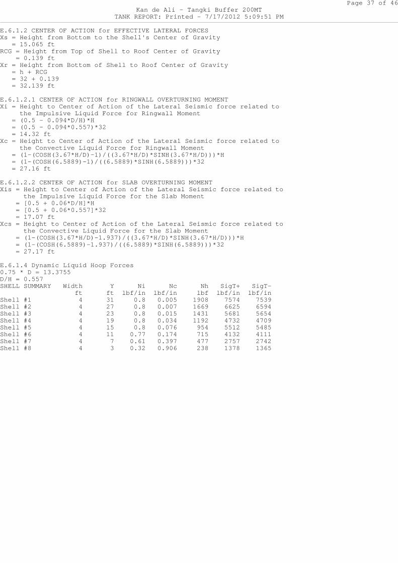
E.6.1.2 CENTER OF ACTION for EFFECTIVE LATERAL FORC ESXs = Height from Bottom to the Shell's Center of Gr avity = 15.065 ftRCG = Height from Top of Shell to Roof Center of Gr avity = 0.139 ftXr = Height from Bottom of Shell to Roof Center of Gravity = h + RCG = 32 + 0.139 = 32.139 ft
E.6.1.2.1 CENTER OF ACTION for RINGWALL OVERTURNING MOMENTXi = Height to Center of Action of the Lateral Seis mic force related to the Impulsive Liquid Force for Ringwall Moment = (0.5 - 0.094*D/H)*H = (0.5 - 0.094*0.557)*32 = 14.32 ftXc = Height to Center of Action of the Lateral Seis mic force related to the Convective Liquid Force for Ringwall Momen t = (1-(COSH(3.67*H/D)-1)/((3.67*H/D)*SINH(3.67*H/ D)))*H = (1-(COSH(6.5889)-1)/((6.5889)*SINH(6.5889)))*3 2 = 27.16 ft
E.6.1.2.2 CENTER OF ACTION for SLAB OVERTURNING MOM ENTXis = Height to Center of Action of the Lateral Sei smic force related to the Impulsive Liquid Force for the Slab Momen t = [0.5 + 0.06*D/H]*H = [0.5 + 0.06*0.557]*32 = 17.07 ftXcs = Height to Center of Action of the Lateral Sei smic force related to the Convective Liquid Force for the Slab Mome nt = (1-(COSH(3.67*H/D)-1.937)/((3.67*H/D)*SINH(3. 67*H/D)))*H = (1-(COSH(6.5889)-1.937)/((6.5889)*SINH(6.5889 )))*32 = 27.17 ft
E.6.1.4 Dynamic Liquid Hoop Forces0.75 * D = 13.3755D/H = 0.557SHELL SUMMARY Width Y Ni Nc Nh SigT+ SigT- ft ft lbf/in lbf/in l bf lbf/in lbf/inShell #1 4 31 0.8 0.005 19 08 7574 7539Shell #2 4 27 0.8 0.007 16 69 6625 6594Shell #3 4 23 0.8 0.015 14 31 5681 5654Shell #4 4 19 0.8 0.034 11 92 4732 4709Shell #5 4 15 0.8 0.076 9 54 5512 5485Shell #6 4 11 0.77 0.174 7 15 4132 4111Shell #7 4 7 0.61 0.397 4 77 2757 2742Shell #8 4 3 0.32 0.906 2 38 1378 1365
Page 38 of 46Kan de Ali - Tangki Buffer 200MT
TANK REPORT: Printed - 7/17/2012 5:09:51 PM
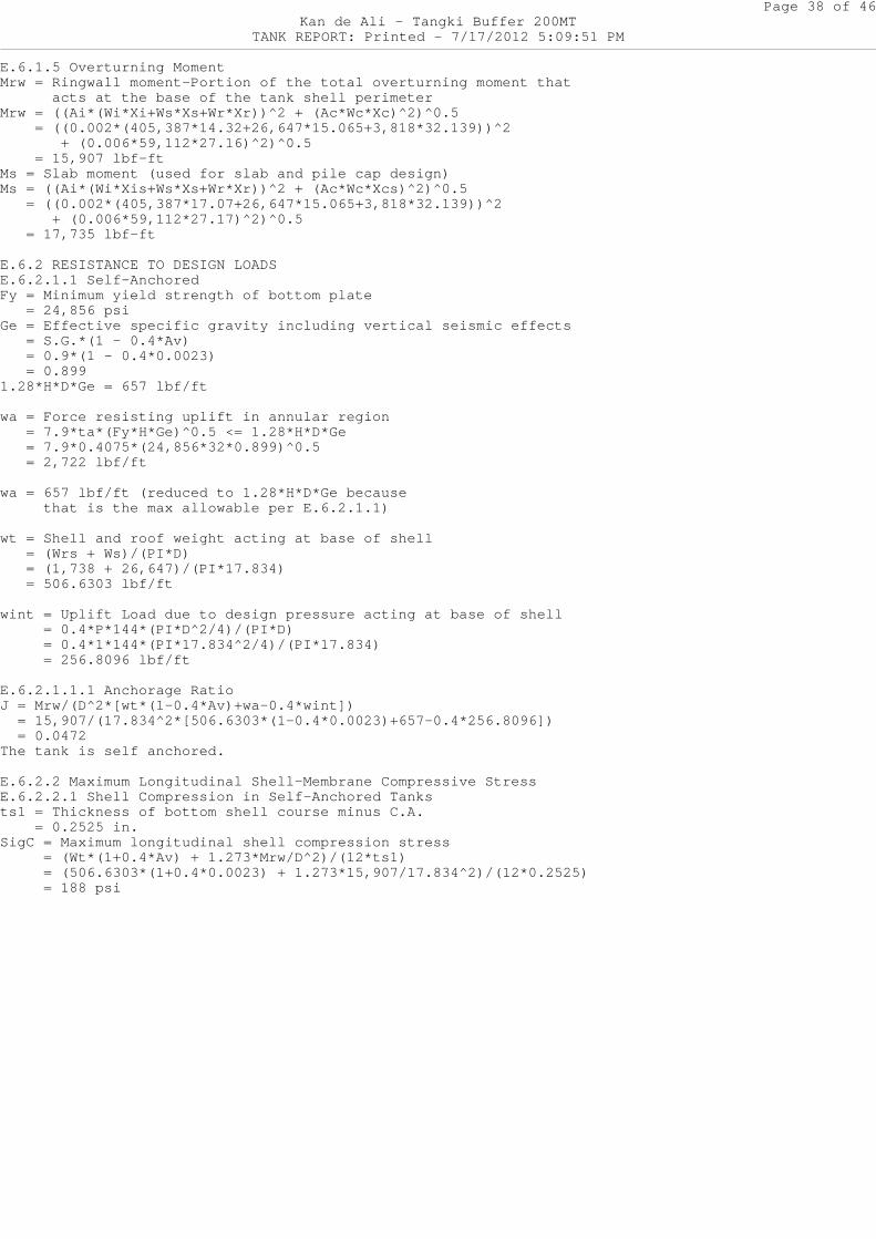
E.6.1.5 Overturning MomentMrw = Ringwall moment—Portion of the total overturn ing moment that acts at the base of the tank shell perimeterMrw = ((Ai*(Wi*Xi+Ws*Xs+Wr*Xr))^2 + (Ac*Wc*Xc)^2)^0 .5 = ((0.002*(405,387*14.32+26,647*15.065+3,818*32 .139))^2 + (0.006*59,112*27.16)^2)^0.5 = 15,907 lbf-ftMs = Slab moment (used for slab and pile cap design )Ms = ((Ai*(Wi*Xis+Ws*Xs+Wr*Xr))^2 + (Ac*Wc*Xcs)^2)^ 0.5 = ((0.002*(405,387*17.07+26,647*15.065+3,818*32. 139))^2 + (0.006*59,112*27.17)^2)^0.5 = 17,735 lbf-ft
E.6.2 RESISTANCE TO DESIGN LOADSE.6.2.1.1 Self-AnchoredFy = Minimum yield strength of bottom plate = 24,856 psiGe = Effective specific gravity including vertical seismic effects = S.G.*(1 - 0.4*Av) = 0.9*(1 - 0.4*0.0023) = 0.8991.28*H*D*Ge = 657 lbf/ft
wa = Force resisting uplift in annular region = 7.9*ta*(Fy*H*Ge)^0.5 <= 1.28*H*D*Ge = 7.9*0.4075*(24,856*32*0.899)^0.5 = 2,722 lbf/ft
wa = 657 lbf/ft (reduced to 1.28*H*D*Ge because that is the max allowable per E.6.2.1.1)
wt = Shell and roof weight acting at base of shell = (Wrs + Ws)/(PI*D) = (1,738 + 26,647)/(PI*17.834) = 506.6303 lbf/ft
wint = Uplift Load due to design pressure acting at base of shell = 0.4*P*144*(PI*D^2/4)/(PI*D) = 0.4*1*144*(PI*17.834^2/4)/(PI*17.834) = 256.8096 lbf/ft
E.6.2.1.1.1 Anchorage RatioJ = Mrw/(D^2*[wt*(1-0.4*Av)+wa-0.4*wint]) = 15,907/(17.834^2*[506.6303*(1-0.4*0.0023)+657-0 .4*256.8096]) = 0.0472The tank is self anchored.
E.6.2.2 Maximum Longitudinal Shell-Membrane Compres sive StressE.6.2.2.1 Shell Compression in Self-Anchored Tanksts1 = Thickness of bottom shell course minus C.A. = 0.2525 in.SigC = Maximum longitudinal shell compression stres s = (Wt*(1+0.4*Av) + 1.273*Mrw/D^2)/(12*ts1) = (506.6303*(1+0.4*0.0023) + 1.273*15,907/17.8 34^2)/(12*0.2525) = 188 psi
Page 39 of 46Kan de Ali - Tangki Buffer 200MT
TANK REPORT: Printed - 7/17/2012 5:09:51 PM
E.6.2.2.3 Allowable Longitudinal Shell-Membrane Com pression StressFty = Minimum specified yield strength of shell cou rse = 29,800 psiG*H*D^2/ts1^2 = 143,670Fc = Allowable longitudinal shell-membrane compress ive stress = 10^6*ts1/(2.5*D) + 600*(G*H)^0.5 = 10^6*0.2525/(2.5*17.834) + 600*(0.9*32)^0.5 = 8,883 psiShell Membrane Compressive Stress OK
E.6.2.4 Hoop StressesShell Summary SigT+ Sd*1.333 Fy*.9*E Allowable t-Min Shell OK Membrane StressShell #1 7574 29993. 18774. 18774. 0.1644 YesShell #2 6625 29993. 18774. 18774. 0.1516 YesShell #3 5681 29993. 18774. 18774. 0.1389 YesShell #4 4732 29993. 18774. 18774. 0.1261 YesShell #5 5512 29993. 18774. 18774. 0.1134 YesShell #6 4132 29993. 18774. 18774. 0.1007 YesShell #7 2757 29993. 18774. 18774. 0.088 YesShell #8 1378 29993. 18774. 18774. 0.0752 Yes
Shell Membrane Hoop Stress OK? True
Tank Adequate with No Anchors? True
E.6.2.1.2 Mechanically-AnchoredNumber of Anchors = 80Max Spacing = 10 ftActual Spacing = 0.7 ftMinimum # Anchors = 6Wab = Design Uplift Load on Anchors per unit circum ferential length = (1.273*Mrw)/D^2 - wt*(1-0.4*Av) + wint = (1.273*15,907)/17.834^2 - 506.6303*(1-0.4*0.0 023) + 256.8096 = -186 lbf/ftPab = Anchor seismic design load = Wab*PI*D/Na = -186*PI*17.834/80 = -130 lbfPa = Anchorage chair design load = 3 * Pab = 3*-130 = -390 lbf
E.6.2.2.2 Shell Compression in Mechanically-Anchore d TanksSigC_anchored = Maximum longitudinal shell compress ion stress = (Wt*(1+0.4*Av) + 1.273*Mrw/D^2)/(12*ts1) = (506.6303*(1+0.4*0.0023) + 1.273*15,907/17.8 34^2)/(12*0.2525) = 188 psiFc = longitudinal shell-membrane compression stress = 8,883 psiShell Membrane Compressive Stress OK
Shell Membrane Hoop Stress OK? True
Tank Adequate with Anchors? True
Page 40 of 46Kan de Ali - Tangki Buffer 200MT
TANK REPORT: Printed - 7/17/2012 5:09:51 PM
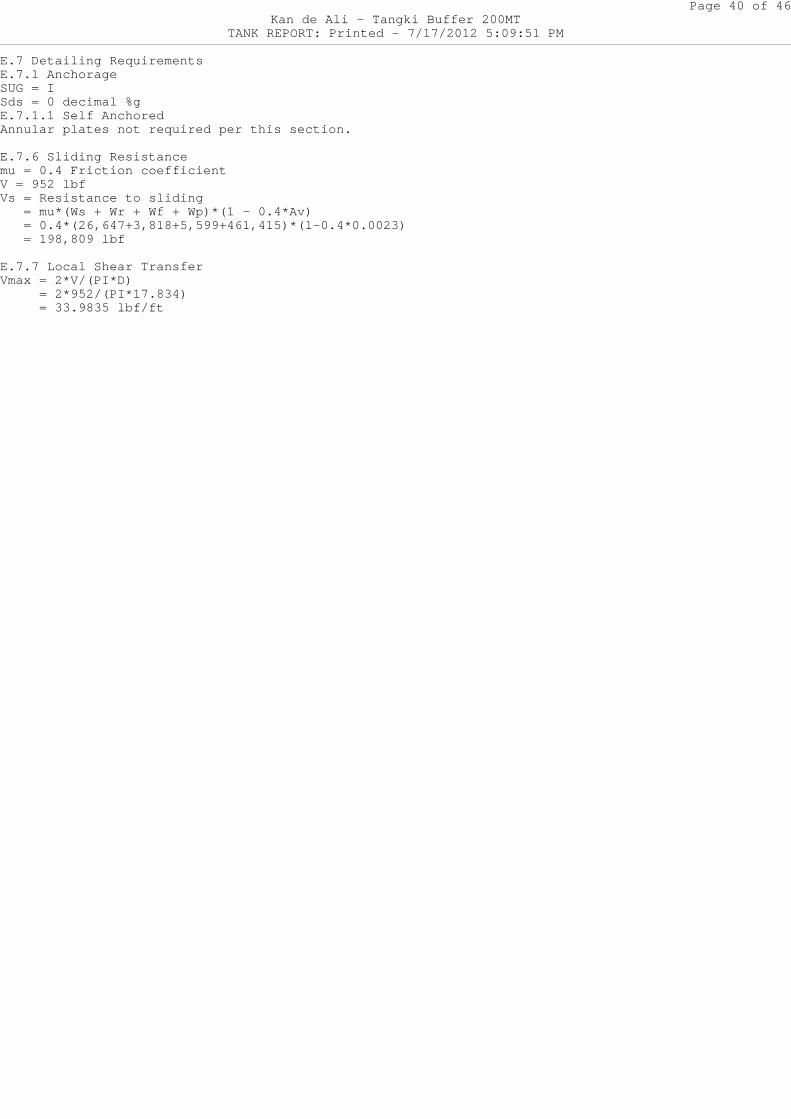
E.7 Detailing RequirementsE.7.1 AnchorageSUG = ISds = 0 decimal %gE.7.1.1 Self AnchoredAnnular plates not required per this section.
E.7.6 Sliding Resistancemu = 0.4 Friction coefficientV = 952 lbfVs = Resistance to sliding = mu*(Ws + Wr + Wf + Wp)*(1 - 0.4*Av) = 0.4*(26,647+3,818+5,599+461,415)*(1-0.4*0.0023 ) = 198,809 lbf
E.7.7 Local Shear TransferVmax = 2*V/(PI*D) = 2*952/(PI*17.834) = 33.9835 lbf/ft
Page 41 of 46Kan de Ali - Tangki Buffer 200MT
TANK REPORT: Printed - 7/17/2012 5:09:51 PM
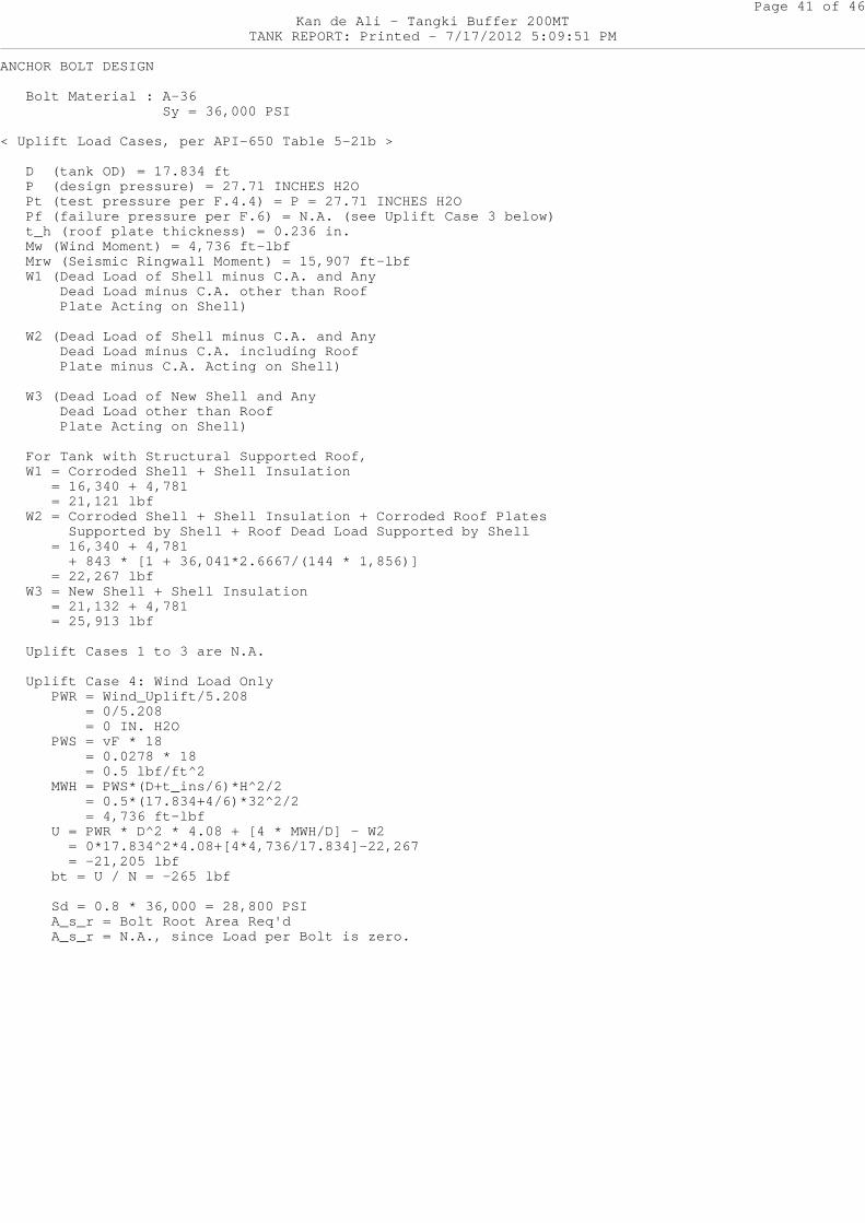
ANCHOR BOLT DESIGN
Bolt Material : A-36 Sy = 36,000 PSI
< Uplift Load Cases, per API-650 Table 5-21b >
D (tank OD) = 17.834 ft P (design pressure) = 27.71 INCHES H2O Pt (test pressure per F.4.4) = P = 27.71 INCHES H2O Pf (failure pressure per F.6) = N.A. (see Uplift Case 3 below) t_h (roof plate thickness) = 0.236 in. Mw (Wind Moment) = 4,736 ft-lbf Mrw (Seismic Ringwall Moment) = 15,907 ft-lbf W1 (Dead Load of Shell minus C.A. and Any Dead Load minus C.A. other than Roof Plate Acting on Shell)
W2 (Dead Load of Shell minus C.A. and Any Dead Load minus C.A. including Roof Plate minus C.A. Acting on Shell)
W3 (Dead Load of New Shell and Any Dead Load other than Roof Plate Acting on Shell)
For Tank with Structural Supported Roof, W1 = Corroded Shell + Shell Insulation = 16,340 + 4,781 = 21,121 lbf W2 = Corroded Shell + Shell Insulation + Corrode d Roof Plates Supported by Shell + Roof Dead Load Support ed by Shell = 16,340 + 4,781 + 843 * [1 + 36,041*2.6667/(144 * 1,856)] = 22,267 lbf W3 = New Shell + Shell Insulation = 21,132 + 4,781 = 25,913 lbf
Uplift Cases 1 to 3 are N.A.
Uplift Case 4: Wind Load Only PWR = Wind_Uplift/5.208 = 0/5.208 = 0 IN. H2O PWS = vF * 18 = 0.0278 * 18 = 0.5 lbf/ft^2 MWH = PWS*(D+t_ins/6)*H^2/2 = 0.5*(17.834+4/6)*32^2/2 = 4,736 ft-lbf U = PWR * D^2 * 4.08 + [4 * MWH/D] - W2 = 0*17.834^2*4.08+[4*4,736/17.834]-22,267 = -21,205 lbf bt = U / N = -265 lbf
Sd = 0.8 * 36,000 = 28,800 PSI A_s_r = Bolt Root Area Req'd A_s_r = N.A., since Load per Bolt is zero.
Page 42 of 46Kan de Ali - Tangki Buffer 200MT
TANK REPORT: Printed - 7/17/2012 5:09:51 PM
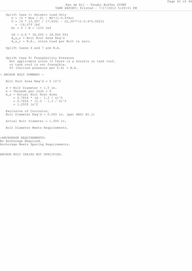
Uplift Case 5: Seismic Load Only U = [4 * Mrw / D] - W2*(1-0.4*Av) U = [4 * 15,907 / 17.834] - 22,267*(1-0.4*0.0 023) = -18,679 lbf bt = U / N = -233 lbf
Sd = 0.8 * 36,000 = 28,800 PSI A_s_r = Bolt Root Area Req'd A_s_r = N.A., since Load per Bolt is zero.
Uplift Cases 6 and 7 are N.A.
Uplift Case 8: Frangibility Pressure Not applicable since if there is a knuckle on tank roof, or tank roof is not frangible. Pf (failure pressure per F.6) = N.A.
< ANCHOR BOLT SUMMARY >
Bolt Root Area Req'd = 0 in^2
d = Bolt Diameter = 1.5 in. n = Threads per inch = 6 A_s = Actual Bolt Root Area = 0.7854 * (d - 1.3 / n)^2 = 0.7854 * (1.5 - 1.3 / 6)^2 = 1.2935 in^2
Exclusive of Corrosion, Bolt Diameter Req'd = 0.065 in. (per ANSI B1.1)
Actual Bolt Diameter = 1.500 in.
Bolt Diameter Meets Requirements.
<ANCHORAGE REQUIREMENTS>No Anchorage Required.Anchorage Meets Spacing Requirements.
ANCHOR BOLT CHAIRS NOT SPECIFIED.
Page 43 of 46Kan de Ali - Tangki Buffer 200MT
TANK REPORT: Printed - 7/17/2012 5:09:51 PM
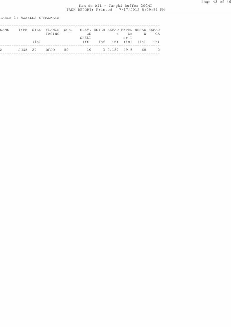
TABLE 1: NOZZLES & MANWAYS
--------------------------------------------------- -------------------NAME TYPE SIZE FLANGE SCH. ELEV. WEIGH REPA D REPAD REPAD REPAD FACING ON t Do W CA SHELL or L (in) (ft) lbf (in ) (in) (in) (in)--------------------------------------------------- -------------------A SHNZ 24 RFSO 80 10 3 0.18 7 49.5 60 0--------------------------------------------------- -------------------
Page 44 of 46Kan de Ali - Tangki Buffer 200MT
TANK REPORT: Printed - 7/17/2012 5:09:51 PM
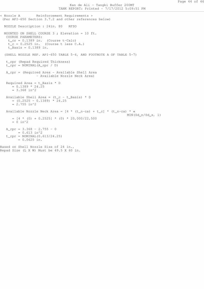
< Nozzle A Reinforcement Requirements > (Per API-650 Section 3.7.2 and other references be low)
NOZZLE Description : 24in. 80 RFSO
MOUNTED ON SHELL COURSE 3 ; Elevation = 10 ft.
COURSE PARAMETERS: t_cr = 0.1389 in. (Course t-Calc) t_c = 0.2525 in. (Course t less C.A.) t_Basis = 0.1389 in.
(SHELL NOZZLE REF. API-650 TABLE 5-6, AND FOOTNOT E A OF TABLE 5-7)
t_rpr (Repad Required Thickness) t_rpr = NOMINAL(A_rpr / D)
A_rpr = (Required Area - Available Shell Area - Available Nozzle Neck Area)
Required Area = t_Basis * D = 0.1389 * 24.25 = 3.368 in^2
Available Shell Area = (t_c - t_Basis) * D = (0.2525 - 0.1389) * 24.25 = 2.755 in^2
Available Nozzle Neck Area = [4 * (t_n-ca) + t_c ] * (t_n-ca) * « MIN(Sd_n/Sd_s, 1) = [4 * (0) + 0.2525] * (0) * 20,000/22,500 = 0 in^2
A_rpr = 3.368 - 2.755 - 0 = 0.613 in^2 t_rpr = NOMINAL(0.613/24.25) = 0.0625 in.
Based on Shell Nozzle Size of 24 in.,Repad Size (L X W) Must be 49.5 X 60 in.
Page 45 of 46Kan de Ali - Tangki Buffer 200MT
TANK REPORT: Printed - 7/17/2012 5:09:51 PM
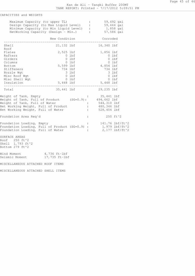
CAPACITIES and WEIGHTS
Maximum Capacity (to upper TL) : 59,492 gal Design Capacity (to Max Liquid Level) : 59,444 gal Minimum Capacity (to Min Liquid Level) : 1,858 gal NetWorking Capacity (Design - Min.) : 57,586 gal
New Condition Corroded ------------------------------------------------- ---------- Shell 21,132 lbf 16,340 lbf Roof Plates 2,525 lbf 1,856 lbf Rafters 0 lbf 0 lbf Girders 0 lbf 0 lbf Columns 0 lbf 0 lbf Bottom 5,599 lbf 4,854 lbf Stiffeners 734 lbf 734 lbf Nozzle Wgt 3 lbf 3 lbf Misc Roof Wgt 0 lbf 0 lbf Misc Shell Wgt 0 lbf 0 lbf Insulation 5,448 lbf 5,448 lbf ------------------------------------------------- ---------- Total 35,441 lbf 29,235 lbf
Weight of Tank, Empty : 35,441 lbfWeight of Tank, Full of Product (SG=0.9): 4 94,662 lbfWeight of Tank, Full of Water : 544,310 lbfNet Working Weight, Full of Product : 480,346 lbfNet Working Weight, Full of Water : 528,404 lbf
Foundation Area Req'd : 250 ft^2
Foundation Loading, Empty : 141.76 lbf/ft^2Foundation Loading, Full of Product (SG=0.9) : 1,979 lbf/ft^2Foundation Loading, Full of Water : 2,177 lbf/ft^2
SURFACE AREASRoof 250 ft^2Shell 1,793 ft^2Bottom 279 ft^2
Wind Moment 4,736 ft-lbfSeismic Moment 17,735 ft-lbf
MISCELLANEOUS ATTACHED ROOF ITEMS
MISCELLANEOUS ATTACHED SHELL ITEMS
Page 46 of 46Kan de Ali - Tangki Buffer 200MT
TANK REPORT: Printed - 7/17/2012 5:09:51 PM
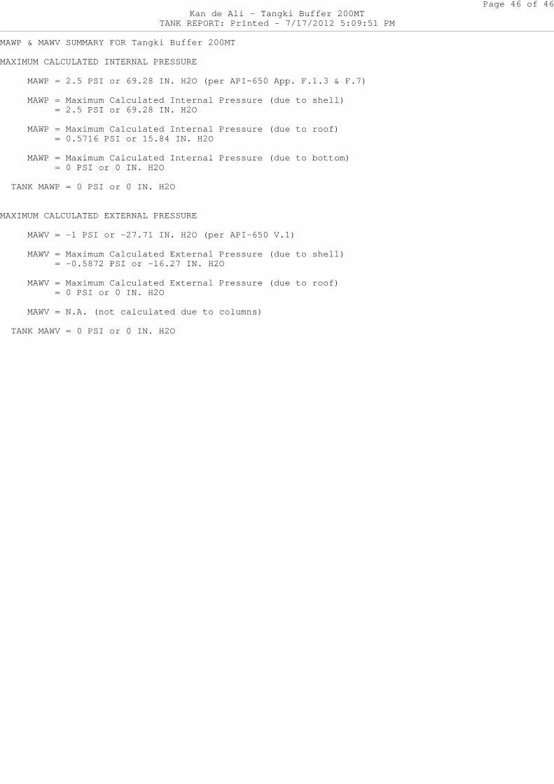
MAWP & MAWV SUMMARY FOR Tangki Buffer 200MT
MAXIMUM CALCULATED INTERNAL PRESSURE
MAWP = 2.5 PSI or 69.28 IN. H2O (per API-650 A pp. F.1.3 & F.7)
MAWP = Maximum Calculated Internal Pressure (d ue to shell) = 2.5 PSI or 69.28 IN. H2O
MAWP = Maximum Calculated Internal Pressure (d ue to roof) = 0.5716 PSI or 15.84 IN. H2O
MAWP = Maximum Calculated Internal Pressure (d ue to bottom) = 0 PSI or 0 IN. H2O
TANK MAWP = 0 PSI or 0 IN. H2O
MAXIMUM CALCULATED EXTERNAL PRESSURE
MAWV = -1 PSI or -27.71 IN. H2O (per API-650 V .1)
MAWV = Maximum Calculated External Pressure (d ue to shell) = -0.5872 PSI or -16.27 IN. H2O
MAWV = Maximum Calculated External Pressure (d ue to roof) = 0 PSI or 0 IN. H2O
MAWV = N.A. (not calculated due to columns)
TANK MAWV = 0 PSI or 0 IN. H2O


![making the switch from cone 10 cone 6 - Smart[in] · PDF fileIn Making the Switch from Cone 10 to Cone 6 Ceramic Glaze Recipes: ... even after the kiln was repaired. Firing to cone](https://img.pdfslide.us/doc/110x75/5a72d6827f8b9abb538e0b7c/making-the-switch-from-cone-10-cone-6-smartin-a-in-making-the-switch-from.jpg)