Embed Size (px)
Citation preview
Budenberg BGH Series
Hydraulic Dead-Weight Testers
Operating and
Maintenance Instructions
Budenberg Gauge Co Ltd4 Gilchrist Road, Northbank Industrial Estate, Irlam
Manchester, United Kingdom, M44 5AY
Tel: +44 (0)161 777 7300 Fax: +44 (0)161 777 7399 E-mail: [email protected]
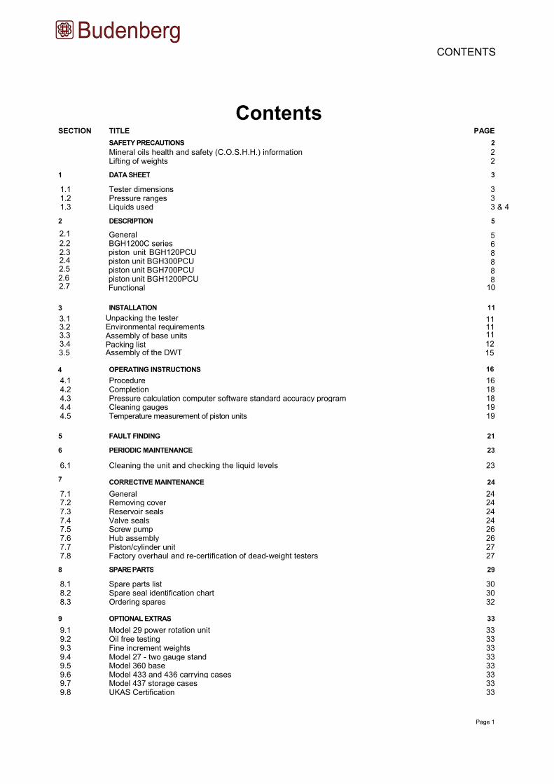
Contents SECTION TITLE PAGE
SAFETY PRECAUTIONS 2
Mineral oils health and safety (C.O.S.H.H.) information 2 Lifting of weights 2
1 DATA SHEET 3
1.1 Tester dimensions 3 1.2 Pressure ranges 3 1.3 Liquids used 3 & 4
2 DESCRIPTION 5
2.1 5 2.2 6 2.3 8 2.4 8 2.5 8 2.6 8 2.7
General BGH1200C seriespiston unit BGH120PCU piston unit BGH300PCU piston unit BGH700PCUpiston unit BGH1200PCU Functional 10
3 INSTALLATION 11
3.1 11 3.2 11 3.3 11
3.4
Unpacking the tester Environmental requirements Assembly of base units Packing list Assembly of the DWT
12
4 OPERATING INSTRUCTIONS 16
4.1 Procedure 16 4.2 Completion 18 4.3 Pressure calculation computer software standard accuracy program 18 4.4 Cleaning gauges 19 4.5 Temperature measurement of piston units 19
5 FAULT FINDING 21
6 PERIODIC MAINTENANCE 23
6.1 Cleaning the unit and checking the liquid levels 23
7 CORRECTIVE MAINTENANCE 24
7.1 General 24 7.2 Removing cover 24 7.3 Reservoir seals 24 7.4 Valve seals 24 7.5 Screw pump 26 7.6 Hub assembly 26 7.7 Piston/cylinder unit 27 7.8 Factory overhaul and re-certification of dead-weight testers 27
8 SPARE PARTS 29
8.1 Spare parts list 30 8.2 Spare seal identification chart 30 8.3 Ordering spares 32
9 OPTIONAL EXTRAS 33
9.1 Model 29 power rotation unit 33 9.2 Oil free testing 33 9.3 Fine increment weights 33 9.4 Model 27 - two gauge stand 33 9.5 Model 360 base 33 9.6 Model 433 and 436 carrying cases 33 9.7 Model 437 storage cases 33 9.8 UKAS Certification 33
Page 1
CONTENTS
3.5 15
Page 2
Safety Precautions
MINERAL OILS HEALTH AND SAFETY (C.O.S.H.H.) INFORMATION
Budenberg provide hydraulic mineral oil in 500 ml containers labelled “ISO VG 22” for use up to 1400 bar in dead-weight testers and pressure comparators. It is no more hazardous than other common lubricating oils.
It is the nature of the way in which this equipment is used, that there could be frequent and/or prolonged skin contact; in a few individuals this could give rise to skin irritation (Keratosis or Dermatitis). The use of an effective barrier cream will greatly reduce this possibility.
DESCRIPTION
Closed flash point: greater than 120°C.
Threshold limit value: 5 mg/m³.
Fire extinguishing media:
Spillage:
Waste disposal:
Soak with absorbent clay or proprietary absorbent.
EMERGENCY TREATMENT OF ACUTE EFFECTS
Ingestion: Do not induce vomiting. Administer 250 ml milk or olive oil.
Aspiration: The main hazard following accidental ingestion is aspiration of liquid into lungs. Send to
hospital immediately.
Inhalation:
Eye Contact:
Remove to fresh air, if nausea persists seek medical attention.
Skin Contact: Where skin rashes or other abnormalities occur as a result of prolonged or repeated contact, medical advice should be obtained as soon as possible.
OTHER LIQUIDS
For some very particular applications we supply specially constructed liquids. Copies of manufacturer’s data will be
sent to users on request.
LIFTING OF WEIGHTS
Care must be taken when lifting the weights for the dead-weight tester. Each weight must be lifted individually and never
attempt to lift stacks of weights on or off the tester.
SAFETY PRECAUTIONS
Wash with copious amounts of water for at least 10 minutes. If irritation results or persists, obtain medical advice.
carbon dioxide/dry chemical foam or water fog.
Burn or dump in approved area.
not above 30°C.
15 g per kg body weight.
Storage:
Oral LD 50:
Page 3
Data Sheet
1.1 TESTER DlMENSIONS
Width = 400 mm
Depth = 400 mm
Height (with BGH300PCU piston unit) = 205 mm
Height (with BGH120PCU piston unit) = 220 mm
Height (with BGH 700 or 1200 piston unit)
Mass - without weights = 17,2 kg (inclusive of piston unit and oil fill)
1 to 120 bar (10 to 1,600 Ib/in2) 2 to 300 bar (30 to 4,000 Ib/in2)
1 to 700 bar (10 to 10,000 Ib/in²) 1 to 1,200 bar (10 to 16,000 Ib/in²)
BGH base with BGH120PCU piston unit BGH base with BGH300PCU piston unit BGH base with BGH700PCU piston unit BGH base with BGH1200PCU piston unit
Model BGH1200C
Model BGH700CW0 to 1,200 bar (0 to 16,000 Ib/in2)
0 to 700 bar (0 to 10,000 Ib/in2)
1.3 LIQUIDS USED
An hydraulic mineral oil viscosity 20 to 37 cSt at 40°C viscosity grade VG20 to VG37 to ISO3448 (BS4231) is used for all the BGH base units except the BGH700CW model. The more viscous oils give lower leak rates athigher pressures (say above 100 bar). Less viscous oils give greater sensitivity at lower pressures. Most users will be able to obtain locally a suitable oil (see below) as used in hydraulic machinery. However for the convenience of users we can supply a 500 ml bottle of oil, viscosity grade VG22.
OILS SUITABLE FOR TESTERS
The following oils are the commercially available oils suitable for use in the dead-weight tester.
ISO 3448 viscosity grade
Approx. SAE viscosity
classification Shell Esso Mobil
VG22 -
Tellus 22 Tellus R22 Nuto H22 DTE 22
VG32 10W
Tellus V32 DTE 24 Nuto H32 DTE Oil Light
VG37
-
Tellus 37
Tellus R37
Tellus T37
Tellus V37
- -
- - -
SECTION 1 - DATA SHEETS
1.2 PRESSURE RANGES
= 280 mm
Page 4
SKYDROL 500B
Model BGH testers for use on Skydrol 500B (a Monsanto product) or any other phosphate ester based fire resistant liquid, should be ordered fitted with Ethylene Polypropylene (EP) seals and tested on Skydrol. EP seals are not suitable for mineral oils.
Note that continual immersion of the cover in Skydrol will cause deterioration. Spillage should be wiped off the cover immediately.
BRAKE LIQUIDS
Model BGH testers for use on non petroleum base brake liquids should be ordered fitted with EP seals and tested on the liquid. This liquid is known by the following names; FMVSS No.116, DOT3 or DOT4, SAE J 1 703, BS AU 174:Part 2, IS04925.
OTHER LIQUIDS
Model BGH testers can be used on silicone based liquids, sebacate based liquids, or inert perfluorinatedpolyethers such as Fluorolube, Fomblin, Halocarbon, which are of the viscosity mentioned above and are chemically inert, being suitable for contact with metals and with the nitrile seals which are standard on the tester. The tester can be supplied as standard tested on mineral oil for the user to clean and fill, or alternatively the tester can be supplied cleaned and tested on any suitable liquid readily available in UK.
MODEL BGH700CW ONLY
Use distilled or demineralised water.
Due to the poor lubricating properties of water, it is Budenberg's recommendation that if possible a 10% medicinal gylcerine/90% distilled or demineralised water mixture (by volume) is used. This will improve pressure seal wear and overall system efficiency.
SECTION 1 - DATA SHEETS
Page 5
Description
2.1 GENERAL
The BGH series dead-weight tester can be supplied in several different configurations. The series is based around the BGH series base unit which is common to all the different configurations. The base unit provides a pressure source, liquid reservoir, control valves and gauge or piston connections. When the base unit is used with one of the BGH120PCU, BGH300PCU, BGH700PCU and BGH1200PCU piston units the configuration provides an high accuracy dead-weight tester. When the base unit is used in the BGH1200C configuration with a high accuracy standard test gauge, it provides a simple to use comparator. The BGH700CW unit is similar to the BGH1200C unit but is supplied in an oil free condition to enable water to be used as the pressurising liquid.
In the dead-weight tester configuration the selected piston unit is normally screwed on to the left hand side pressure block of the base unit and the gauge under test is connected to the right hand pressure block of the base unit. In the comparator configuration a standard gauge is normally connected to the left hand side pressure block of the base unit and the gauge under test is connected to the right hand pressure block of the base unit. The pressure datum of the tester is at the base of the piston and is marked on the piston units.
Any Model BGH1200C comparator can be converted to any dead-weight tester by the addition of the appropriate piston/cylinder unit and weights and any dead-weight tester can be converted to a Model BGH1200C comparator with the addition of an extra gauge stand.
SECTION 2 - DESCRIPTION
Page 6
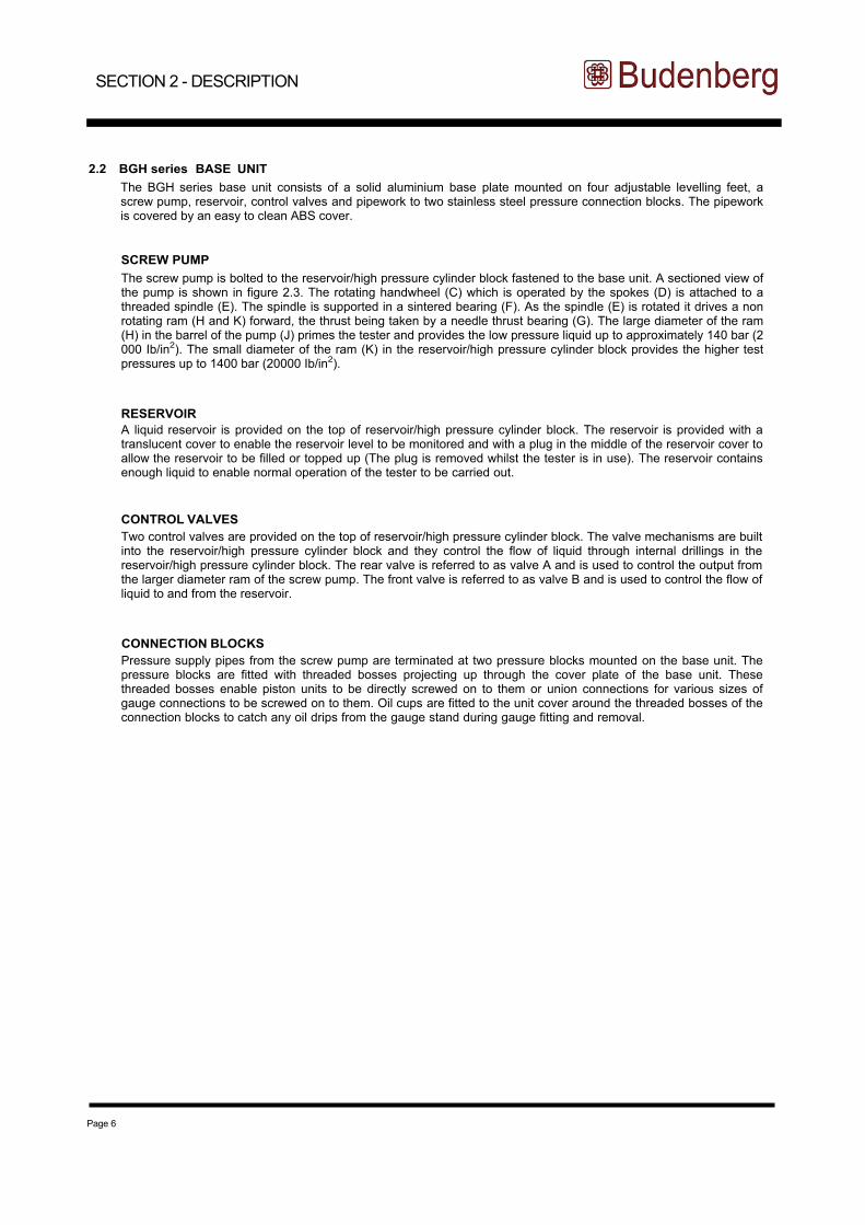
2.2 BGH series BASE UNIT
The BGH series base unit consists of a solid aluminium base plate mounted on four adjustable levelling feet, a screw pump, reservoir, control valves and pipework to two stainless steel pressure connection blocks. The pipework is covered by an easy to clean ABS cover.
SCREW PUMP
The screw pump is bolted to the reservoir/high pressure cylinder block fastened to the base unit. A sectioned view of the pump is shown in figure 2.3. The rotating handwheel (C) which is operated by the spokes (D) is attached to a threaded spindle (E). The spindle is supported in a sintered bearing (F). As the spindle (E) is rotated it drives a non rotating ram (H and K) forward, the thrust being taken by a needle thrust bearing (G). The large diameter of the ram (H) in the barrel of the pump (J) primes the tester and provides the low pressure liquid up to approximately 140 bar (2 000 Ib/in2). The small diameter of the ram (K) in the reservoir/high pressure cylinder block provides the higher test pressures up to 1400 bar (20000 Ib/in2).
RESERVOIR
A liquid reservoir is provided on the top of reservoir/high pressure cylinder block. The reservoir is provided with a translucent cover to enable the reservoir level to be monitored and with a plug in the middle of the reservoir cover to allow the reservoir to be filled or topped up (The plug is removed whilst the tester is in use). The reservoir contains enough liquid to enable normal operation of the tester to be carried out.
CONTROL VALVES
Two control valves are provided on the top of reservoir/high pressure cylinder block. The valve mechanisms are built into the reservoir/high pressure cylinder block and they control the flow of liquid through internal drillings in the reservoir/high pressure cylinder block. The rear valve is referred to as valve A and is used to control the output from the larger diameter ram of the screw pump. The front valve is referred to as valve B and is used to control the flow of liquid to and from the reservoir.
CONNECTION BLOCKS
Pressure supply pipes from the screw pump are terminated at two pressure blocks mounted on the base unit. The pressure blocks are fitted with threaded bosses projecting up through the cover plate of the base unit. These threaded bosses enable piston units to be directly screwed on to them or union connections for various sizes of gauge connections to be screwed on to them. Oil cups are fitted to the unit cover around the threaded bosses of the connection blocks to catch any oil drips from the gauge stand during gauge fitting and removal.
SECTION 2 - DESCRIPTION
Page 7
Sectioned View Of Screw Pump
Fig. 2.3 Sectioned view of screw pump
SECTION 2 - DESCRIPTION
Page 8
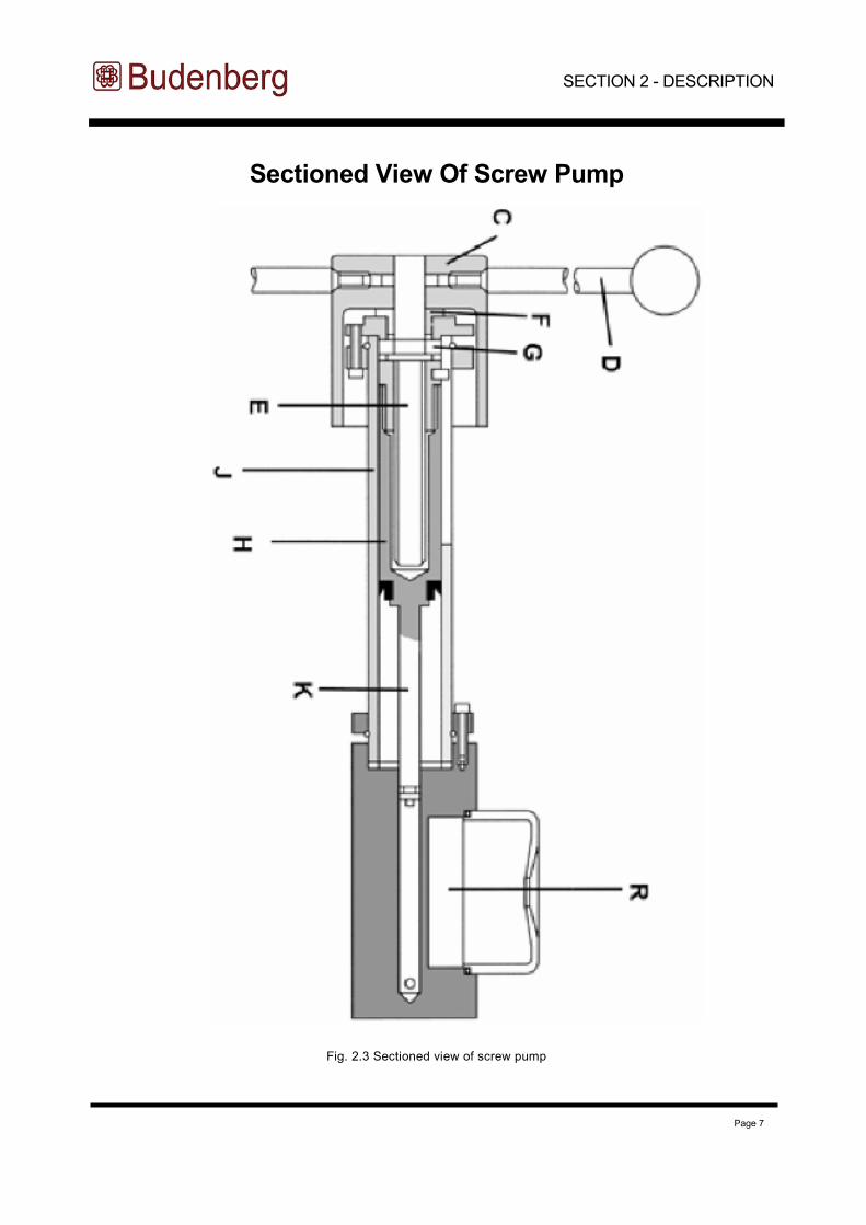
2.3 BGH120 PISTON UNIT
The BGH120PCU piston unit is a simple rugged single range piston unit which covers pressures up to 120 bar (1600 Ib/in2). The cylinder for the piston unit is screwed into a connection which screws on to the base unit pressure connection blocks threaded boss. The piston head carries the calibration weights and is fitted to the end of the piston. A stop on the opposite end of the piston abuts the internal end of the cylinder when the maximum piston extension is reached. A sighting hole is provided in the cylinder wall so that the base of the piston head can be seen and monitored to ensure that the piston head is floating when in use. The pressure datum level of the piston unit is marked on connection used to screw the piston unit cylinder on to the base unit pressure connection block’s threaded boss.
2.4 BGH300PCU PISTON UNIT
The BGH300PCU piston unit is a single range piston unit which covers pressures up to 300 bar (4000 Ib/in2). The cylinder for the piston unit is mounted on a connection which screws on to the base unit pressure connection block threaded boss. The cylinder is fastened to the connection by a special nut into which is fitted an indicator to show when the piston head is floating and also indicate the datum level for the tester. The piston head carries the calibration weights and is carried on a ball at the end of the piston. A stop on the opposite end of the piston abuts the internal end of the cylinder when the maximum piston extension is reached. The piston head is fitted over the outside of the cylinder to prevent accidental damage to the piston and cylinder.
2.5 BGH700PCU PISTON UNIT
The BGH700PCU piston unit is a dual range piston unit covering the range up to 700 bar (10000 Ib/in2). The piston head which carries the calibration weights is operated by two pistons; a low pressure piston and a high pressure piston. As the supply pressure is increased the low pressure piston is operated until the flange on the end of the low pressure piston abuts the end of the low pressure cylinder. As the pressure continues to increase, the high pressure piston operates through the middle of the low pressure piston which is now acting as the high pressure cylinder. Indication of the range in which the piston is operating and that the piston head is floating is given by the position of the piston head as seen against two coloured bands on the cylinder. The pressure datum level of the piston unit is marked on the connection used to screw the piston cylinder unit on to the base unit pressure connection blocks threaded boss.
2.6 BGH1200PCU PISTON UNIT
The BGH1200PCU piston unit is a similar piston unit to the BGH700PCU piston unit except that it covers the pressure range up to 1200 bar (16000 Ib/in2).
SECTION 2 - DESCRIPTION
Page 9
MODEL BGH120PCU MODEL BGH300PCU
MODEL
BGH700PCU,BGH1200PCU
GAUGE STAND
Fig. 2.4 Piston units and gauge stand
SECTION 2 - DESCRIPTION
Page 10
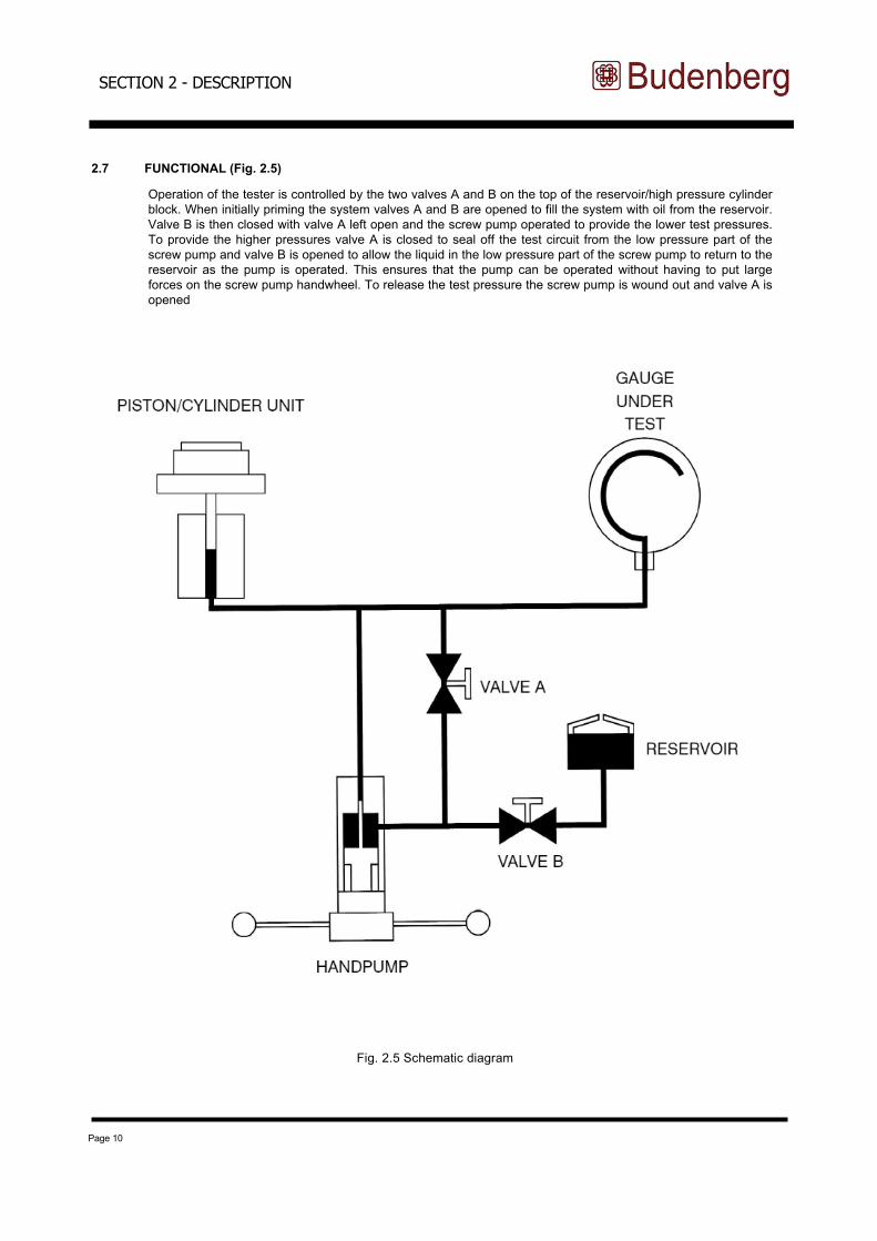
2.7 FUNCTIONAL (Fig. 2.5)
Fig. 2.5 Schematic diagram
SECTION 2 - DESCRIPTION
Operation of the tester is controlled by the two valves A and B on the top of the reservoir/high pressure cylinder block. When initially priming the system valves A and B are opened to fill the system with oil from the reservoir. Valve B is then closed with valve A left open and the screw pump operated to provide the lower test pressures. To provide the higher pressures valve A is closed to seal off the test circuit from the low pressure part of the screw pump and valve B is opened to allow the liquid in the low pressure part of the screw pump to return to the reservoir as the pump is operated. This ensures that the pump can be operated without having to put large forces on the screw pump handwheel. To release the test pressure the screw pump is wound out and valve A is opened
Page 11
Installation
3.1 UNPACKING THE TESTER
As you are unpacking the items examine the items for signs of damage or breakage during transit.
If any items are missing get in touch immediately with Budenberg to inform us of the shortage.
3.2 ENVIRONMENTAL REQUIREMENTS
When siting the tester, if not in a temperature controlled laboratory, look for an area that satisfies the following criteria as much as possible
- a constant temperature area free from draughts and sources of heat or cold
-
- a clean dry area free from corrosive liquids or vapours.
A strong, stable, level table or workbench is required with the capability of supporting the tester plus a full load of test weights and with sufficient space to operate the test unit.
3.3 ASSEMBLY OF BASE UNITS
Fastening Base to Bench
The base is to be mounted on a firm, level table or bench about 0.9 m high. Space is normally required for storing the weights on the left hand side of the bench. The centre line of the front adjustable feet of the unit should be about 40 mm from the front edge of the bench to allow adequate clearance for the handwheel.
(1) Mark the position of the adjustable feet of the unit on the top of the bench.
(2) Position a level plate at the centre of each of the adjustable feet of the unit and screw the plate to the bench to ensure that the tester is rigid.
(3) Fit the base unit on the bench with the adjustable feet on the level plates and the handwheel shaft projecting over the front of the bench.
(4) Screw in the four handwheel spokes into the hub.
(5) Using the spirit level provided, level the unit in both the front / rear axis and the side to side axis by adjusting the four knurled feet. If a piston unit is to be fitted, the levelling procedure should be carried out after the piston unit has been fitted to the dead-weight tester and the spirit level should be placed on the weight carrier during the levelling procedure.
SECTION 3 - INSTALLATION
As soon as possible after delivery, open the packaging of the dead-weight tester and check that you have all the items detailed for your tester in the packing list detailed in section 3.4.
an area free from noise and vibration; if possible an area away from any constantly used pathways
Page 12
FOR ALL MODELS
The tester carton should contain:-
1 - copy of the operating and maintenance instructions (this manual)
1 - BGH series base1 - Tool roll containing:-
1 - Hexagon wrench key 3 mm A/F 2 - 30 mm A/F open ended spanners1- Spirit level 4 - Level plates1 - Bag of seals
1 - G1/2 (1/2” BSP) angle connection (If ordered Separately)
1 - Pointer punch
1 - Pointer remover
1 - Gauge stand
1 - 500 ml bottle of oil
1 - Piston/Cylinder unit (as specified in your order)
1 - Set of weights supplied in separate carton
1 - Certificate of accuracy
1 - Set of connections as ordered
B.S.P N.P.T.
METRIC
1 - G 1/8 1 - 1/8 in
1 - M12 X 1.5 1 - G 1/4 1 - 1/4 in
1 - M20 X 1.5 1 - G 3/8 1 - 3/8 in 1 - G 1/2 1 - 1/2 in
FOR MODEL BGH1200C ONLY
2 - Gauge Stands 1 - Standard gauge (if ordered separately)
FOR MODEL BGH ONLY
1 - Gauge stand
1 - 500 ml bottle of oil
1 - Piston/Cylinder unit (as specified in your order)
1 - Set of weights supplied in separate carton 1 - Certificate of accuracy
FOR ALL OTHER MODELS
1 - Gauge stand 1 - Piston/Cylinder unit (as specified in your order) 1 - Set of weights 1 - Certificate of accuracy (not model BGH1200C)
Fig. 3.1 Packing list (sheet 1 of 3)
SECTION 3 - INSTALLATION
3.4 PACKING LIST
A full packing list for all models of testers is detailed in Fig. 3.1.

Page 13
SETS OF WEIGHTS SUPPLIED FOR DEAD-WEIGHT TESTERS
1) MODEL BGH120
Area = 1/16 in2
Range 1 to 120 bar (or kg/cm2)
or 10 to 1600 lb/in2
Bar
(or kg/cm2)
4 x 20
1 x 18
1 x 10
2 x 4
1 x 2
2 x 1
1 x 0.5
Make up to 1
lb/in2
6 x 200
1 x 180
1 x 100
2 x 40
1 x 20
2 x 10
1 x 5
2) MODEL BGH300 Bar lb/in2
(or kg/cm2)
Area = 1/40 in2 4 x 50 6 x 500
Range 2 to 300 bar (or kg/cm2) 1 x 45 1 x 450
or 30 to 4000 lb/in2 1 x 25 1 x 250
2 x 10 2 x 100
1 x 5 1 x 50
1 x 2.5 1 x 25
1 x 3 1 x 20
Make up to 2 Make up to 30
3) MODEL BGH700 Bar lb/in2
(or kg/cm2)
(Dual range) 5 x 10/100 8 x 100/1000
Area = 1/8 and 1/80 in2 1 x 9/90 1 x 90/900
Range 1 to 700 bar (or kg/cm2) 1 x 5/50 1 x 50/500
or 10 to 10,000 lb/in2 2 x 2/20 2 x 20/200 1 x 1/10 1 x 10/100
1 x 0.5/5 1 x 5/50
Make up to 1/10
Fig. 3.1 Packing list (sheet 2 of 3)
SECTION 3 - INSTALLATION
Page 14
4) Model BGH1200 Bar lb/in2
(or kg/cm2)
(Dual range) 4 x 10/200 6 x 100/2000
Area = 1/8 and 1/160 in2 1 x 9/180 1 x 90/1800 Range 1 to 1200 bar (or kg/cm2) 1 x 5/100 1 x 50/1000
or 10 to 16 000 lb/in2 2 x 2/40 2 x 20/400
1 x 1/20 1 x 10/200
1 x 0.5/10 1 x 5/100 Make up to 1/20
WEIGHT SETS CAN BE PROVIDED IN ALTERNATIVE PRESSURE UNITS AND MANUFACTURED FOR LOCAL GRAVITY. CONSULT YOUR LOCAL DISTRIBUTOR FOR ADVICE ON AVAILABILITY.
Fig. 3.1 Packing list (sheet 3 of 3)
SECTION 3 - INSTALLATION
Page 15
3.5 ASSEMBLY OF THE DEAD-WEIGHT TESTER
(1) Fit the appropriate piston unit for the gauges to be calibrated to the L.H. connection and the gauge stand to the R.H. connection. Ensure that the mating faces are absolutely clean and the 12 mm diameter ‘O’ ring seals are correctly located. Excess force is not required.
(2) Check the level of the tester with the spirit level on the piston unit weight carrier. Level if necessary by using the levelling screws.
(3) Fit the appropriate connection to the gauge stand, using a bonded seal to make the joint and screw a test gauge (for installation use a known gauge) into position, also with a bonded seal. If preferred, a copper or leather washer can be substituted for the bonded seal at the gauge. The loose nut on the tester base enables the gauge to be positioned as required and for back connection gauges the angle connection is screwed into the loose connection.
Assembly of the BGH1200C and BGH700CW units
(1) Install the BGH series base unit as detailed above.(2) Screw in place the two gauge stands.
(3) Ensure that the mating faces are absolutely clean and the 12 mm diameter ‘O’ ring seal is correctly located in its recess. Excess force is not required.
(4) Fit the gauge to be tested (for installation testing use a known gauge) using the appropriate connection to one gauge stand and the standard test gauge to the other. Joints should be made using the bonded seals provided or if preferred copper or leather washers. The loose connections on the tester base enable gauges to be positioned as required.
Filling the base unit with liquid
(1) Remove filler plug from reservoir by slackening screw and prising plug out. (This plug should be left out whilst in use).
(2) O p e n v a l v e s A a n d B .
(3) Wind screw pump handle fully clockwise. (4) Fill reservoir with appropriate liquid. Use the oil supplied or an approved substitute for oil systems or clean
distilled water for the BGH700CW unit. Do not use other liquids. Castor based oils, Skydrol, solvents or similar liquids will attack the seals fitted in the standard tester.
(5)
(6)
Wind screw pump handle fully anti-clockwise. Top up
reservoir if neces sary.
Post assembly test
(1) Carry out a test calibration of a known gauge (Section 4) to ensure that the unit is working correctly.
(2) Release the pressure and remove the test gauge.
NOTE: To remove the gauge from the equipment, use the appropriate size of spanners on the top section of the gauge connection and on the body of the gauge only. Ensure that the lower part of the gauge connection is not rotated as this may release the gauge stand from the base.
(3) The equipment is now ready for use.
SECTION 3 - INSTALLATION
Page 16
SECTION 4 - OPERATING INSTRUCTIONS
Operating Instructions
CAUTION: If the volume required to be filled is very large requiring the use of an additional pump and reservoir to be connected to the tester, it is ESSENTIAL to ensure that valve B is kept open and valve A closed at all times otherwise a high pressure can be built up on the low pressure ram of the screw press and damage caused. To ensure this does not happen we can supply the tester fitted with a relief valve which will release at a set pressure should the valve operation be incorrect. Alternatively we can supply a modified tester and hand pump for this operation. For further information on both items contact Budenberg.
NOTES:
(1) When testing equipment with a large volume, the capacity of the screw pump (65 cc) may be insufficient to reach the pressure required. In this case the equipment should be filled as far as possible with the liquid before connecting it to the comparator, so that the displacement needed is reduced.
(2) The Model BGH700CW is supplied in the oil free condition for use on water. It should always be kept clean and free from contamination and instruments must always be cleaned .
(3) Dirty or chemically contaminated gauges should not be fitted as they contaminate the tester unless they are first cleaned. Severe damage may otherwise be caused to the piston/cylinder unit.
4.1 PROCEDURE
(1)
Load the weight carrier with the weights equivalent to the desired pressure. Do not forget to take the weight of
the carrier into account. Each weight is marked with the pressure equivalent and the piston area. The Model BGH120PCU has a basic 10 Ib/in2 start, for other pressure units a make-up weight is added to the weight carrier for conversion to 1 bar (or kg/cm2). The Model BGH300PCU uses a central screw weight which should be changed for the various pressure units to give basic starts of 30 Ib/in2 or 2 bar (or kg/cm2).
(2) Apply pressure as detailed in the ‘To apply pressure’ sub-section.
Model BGH700 and BGH1200
(1) Load the weight carrier with the weights equivalent to the desired pressure. Each weight is marked with two pressures, one for the low pressure range and one for the high pressure range and the equivalent weight of the carrier must also be taken into account. The testers have a basic 10 Ib/in2 start, for other pressure units a makeup weight is added to the weight carrier for conversion to 1 bar (or kg/cm2).
Model BGH120 and BGH300
Page 17
SECTION 4 - OPERATING INSTRUCTIONS
TO APPLY PRESSURE
For pressures up to 140 bar (about 2000 Ib/in2)
(1) Close valve B (valve A remaining open).
(2) Wind screw pump handle clockwise. This will generate pressure up to approximately 140 bar or 2000 Ib/in2, as handle is wound in. When handle becomes stiff to rotate this will indicate that the pressure limit for this range has been reached.
For pressures above 140 bar
(1 ) Ensure valve B closed and valve A open.
(2) Wind screw pump handle clockwise until the handle becomes stiff to operate.
(3) C lose va l ve A and open va l ve B .
(4) Continue to wind screw pump handle clockwise. This will generate pressure up to approximately 1,400 bar or 20,000 Ib/in2. The model BGH120PCU piston is floating when the underside of the piston head has risen to between 1mm and 7 mm above the top face of the cylinder.The model BGH300PCU piston is floating when the bottom edge of the auxiliary cylinder fitted to the piston head has risen to a position within the knurled portion on the stud fitted to this unit.
For the BGH700PCU and BGH1200PCU models the piston rises and the piston head skirt floats within the blue band which corresponds to the low pressure range. The bands are easily visible from a seated position. To engage the high pressure range apply further pressure with the screw pump until the piston lifts higher and the piston head skirt floats within the red band.
A slight leakage through the vent hole of the piston/cylinder unit is normal.
DURING CALIBRATION
When the tester is correctly set up and there are no leaks the piston head should “float” for many minutes without it being necessary to touch the screw pump handwheel. On the initial setting up, however, there may be some air trapped in the base of the piston/cylinder unit. As this leaks past the piston the weights may fall slightly but it will only be for a matter of a few minutes until the air has escaped. If the piston continues to fall check the connections for leaks.
During calibration the weights should be rotated by hand. It is desirable that the weights should only be rotated when approximately the correct pressure is obtained. For any dual range unit, changing from one range to the other with the weights spinning does no harm. Weights should not be brought to rest by fully releasing the pressure and allowing the piston head to rotate against its stop under the full load of the weight pile.
Stops come into action if the pressure is too high or too low and it is essential that the weights should be spinning freely whilst taking readings. At the lowest pressures the weights will not spin for more than a few seconds unless a very thin oil is used, but provided the weight is rotated by hand immediately before taking a reading and is obviously “floating” an accurate reading will be given.
Page 18
SECTION 4 - OPERATING INSTRUCTIONS
DATUM LEVELS
When testing gauges on liquid it is occasionally necessary to take into account heads of liquid since a height difference of
10mm corresponds to approximately 1 mbar. The datum levels of the models BGH120PCU, BGH700PCU and BGH1200PCU units are marked with a groove on the outer diameter of the piston unit. The datum level of the model BGH300PCU is at the bottom of the knurled portion of the stud fitted to the unit. It should be noted that when the tester is re-calibrated by a laboratory other than Budenberg, the datum level at which the tests have been carried out may differ from this standard and therefore allowance should be made for any variation.
4.2 COMPLETION
(1)
(2)
(3)
(4)
After the test is finished, stop the weights rotating. Wind screw pump handle fully anti-clockwise to lower pressure. Gently open valve A or B to release residual pressure. Ensure that both valves A and B are fully open.
The comparator/dead weight tester is now ready for another test and any residual pressure is relieved.
4.3 PRESSURE CALCULATION COMPUTER SOFTWARE STANDARD ACCURACY PROGRAM
This software enables the user to define his equipment and local conditions (gravity, temperature), so that when nominal pressures are entered, actual achieved pressures are displayed.
These actual pressures will then be to the standard accuracy of the tester.
To achieve the improved standard accuracy the user must enter the correction factor given on the improved accuracy certificate supplied with the piston unit.
Default conditions are input at Budenberg but once the user alters these, his values then become the default. (No need to repeatedly insert your values.)
NOTE: This program has been written to aid users to maintain the standard of accuracy of Budenberg dead-weight testers. It has not been written for use with any other make of dead-weight tester.
The software can be accessed from the supplied CD in the folder "Customer Software" & "Standard Accuracy DWT"
Page 19
SECTION 4 - OPERATING INSTRUCTIONS
4.4 CLEANING GAUGES
WARNING
THIS CLEANING/DEGREASING PROCESS IS ONLY SUITABLE FOR USE WITH PRESSURE GAUGES WITH EITHER PHOSPHOR BRONZE, BERYLLIUM COPPER, MONEL OR STAINLESS STEEL BOURDON TUBES IN THE FORM OF A ‘C’.
IT IS NOT ADVISABLE TO DEGREASE PRESSURE GAUGES WITH STEEL BOURDON TUBES SINCE A VERY SMALL AMOUNT OF CORROSION ON THE BORE OF A BOURDON TUBE CAN CAUSE INACCURACIES OF READING AND EARLY FAILURE OF THE TUBE.
THIS METHOD OF CLEANING IS NOT SUITABLE FOR USE WITH PRESSURE GAUGES WHICH ARE FITTED WITH COILED BOURDON TUBES, NOR ANY GAUGES WHICH ARE TO BE USED ON OXYGEN, AS COMPLETE REMOVAL OF OIL IS NOT ASSURED, REFER TO MANUFACTURER.
EQUIPMENT
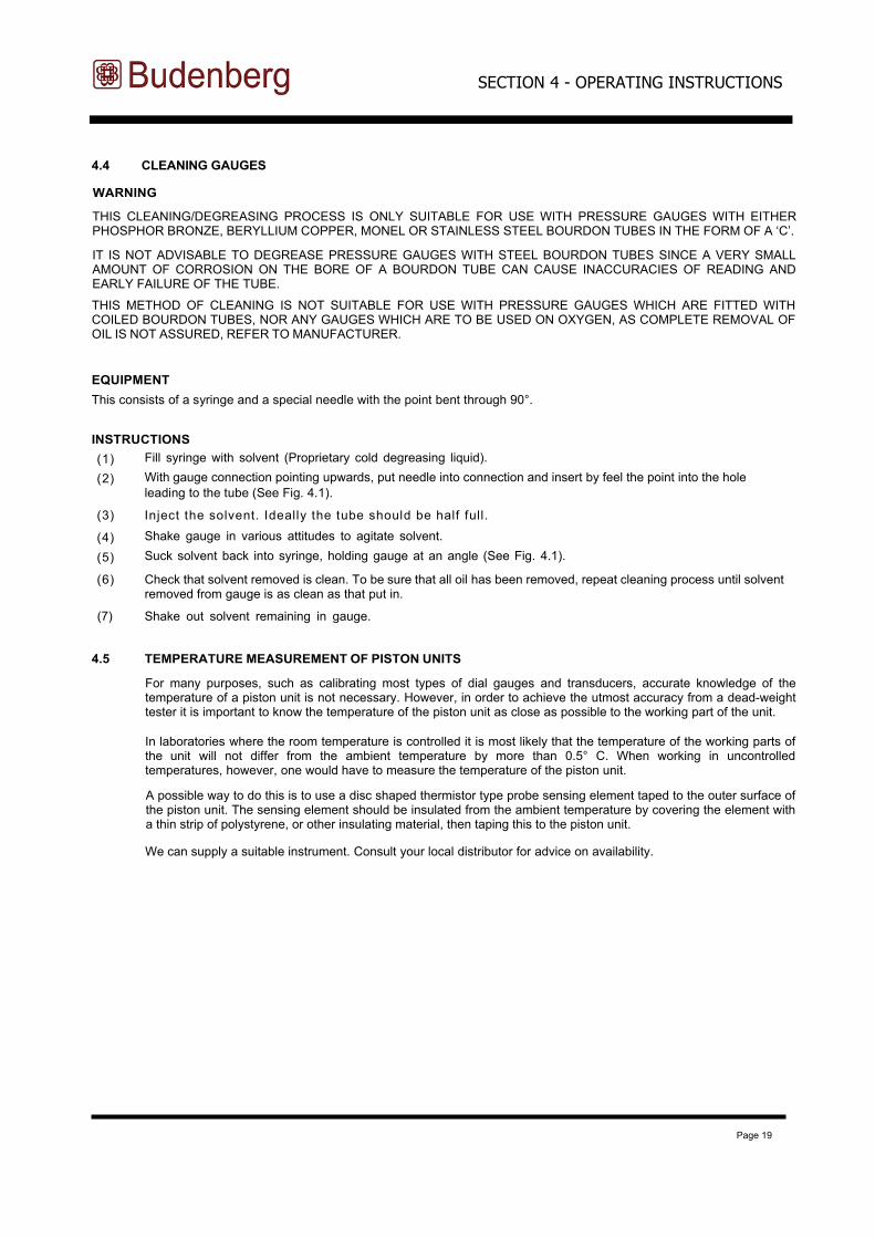
This consists of a syringe and a special needle with the point bent through 90°.
INSTRUCTIONS
(1)
(2)
Fill syringe with solvent (Proprietary cold degreasing liquid).
With gauge connection pointing upwards, put needle into connection and insert by feel the point into the hole
leading to the tube (See Fig. 4.1).
(3) Inject the solvent. Ideally the tube should be half full.
(4)
(5)
Shake gauge in various attitudes to agitate solvent. Suck solvent back into syringe, holding gauge at an angle (See Fig. 4.1).
(6) Check that solvent removed is clean. To be sure that all oil has been removed, repeat cleaning process until solvent removed from gauge is as clean as that put in.
(7) Shake out solvent remaining in gauge.
4.5 TEMPERATURE MEASUREMENT OF PISTON UNITS
For many purposes, such as calibrating most types of dial gauges and transducers, accurate knowledge of the temperature of a piston unit is not necessary. However, in order to achieve the utmost accuracy from a dead-weight tester it is important to know the temperature of the piston unit as close as possible to the working part of the unit.
In laboratories where the room temperature is controlled it is most likely that the temperature of the working parts of the unit will not differ from the ambient temperature by more than 0.5° C. When working in uncontrolled temperatures, however, one would have to measure the temperature of the piston unit.
A possible way to do this is to use a disc shaped thermistor type probe sensing element taped to the outer surface of the piston unit. The sensing element should be insulated from the ambient temperature by covering the element with a thin strip of polystyrene, or other insulating material, then taping this to the piston unit.
We can supply a suitable instrument. Consult your local distributor for advice on availability.
Page 20
SECTION 4 - OPERATING INSTRUCTIONS
Fig. 4.1 Cleaning of gauges
Fault Finding
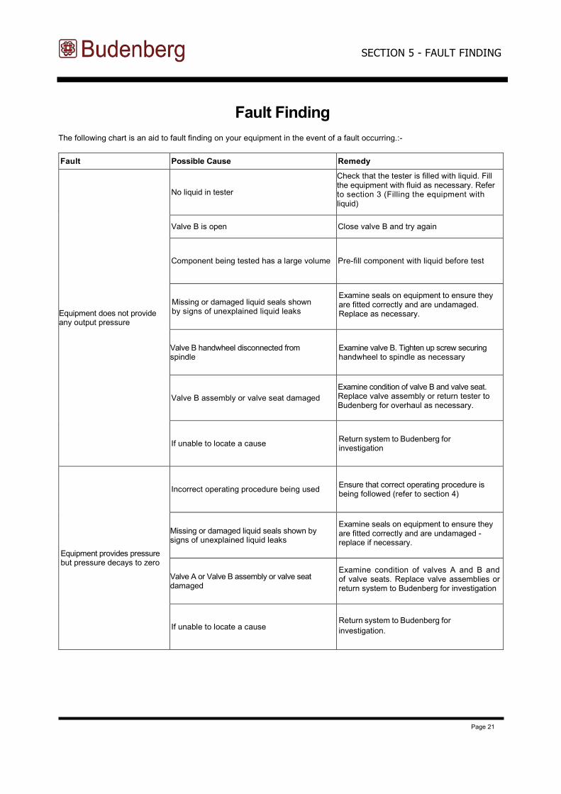
The following chart is an aid to fault finding on your equipment in the event of a fault occurring.:-
Fault Possible Cause Remedy
Equipment does not provide any output pressure
No liquid in tester
Check that the tester is filled with liquid. Fill the equipment with fluid as necessary. Refer to section 3 (Filling the equipment with liquid)
Valve B is open Close valve B and try again
Component being tested has a large volume Pre-fill component with liquid before test
Missing or damaged liquid seals shown by signs of unexplained liquid leaks
Examine seals on equipment to ensure they are fitted correctly and are undamaged. Replace as necessary.
Valve B handwheel disconnected from spindle
Examine valve B. Tighten up screw securing handwheel to spindle as necessary
Valve B assembly or valve seat damaged
Examine condition of valve B and valve seat. Replace valve assembly or return tester to Budenberg for overhaul as necessary.
If unable to locate a cause Return system to Budenberg for investigation
Equipment provides pressure but pressure decays to zero
Incorrect operating procedure being used Ensure that correct operating procedure is being followed (refer to section 4)
Missing or damaged liquid seals shown by signs of unexplained liquid leaks
Examine seals on equipment to ensure they are fitted correctly and are undamaged - replace if necessary.
Valve A or Valve B assembly or valve seat damaged
Examine condition of valves A and B and of valve seats. Replace valve assemblies or return system to Budenberg for investigation
If unable to locate a cause Return system to Budenberg for
investigation.
SECTION 5 - FAULT FINDING
Page 21
Page 22
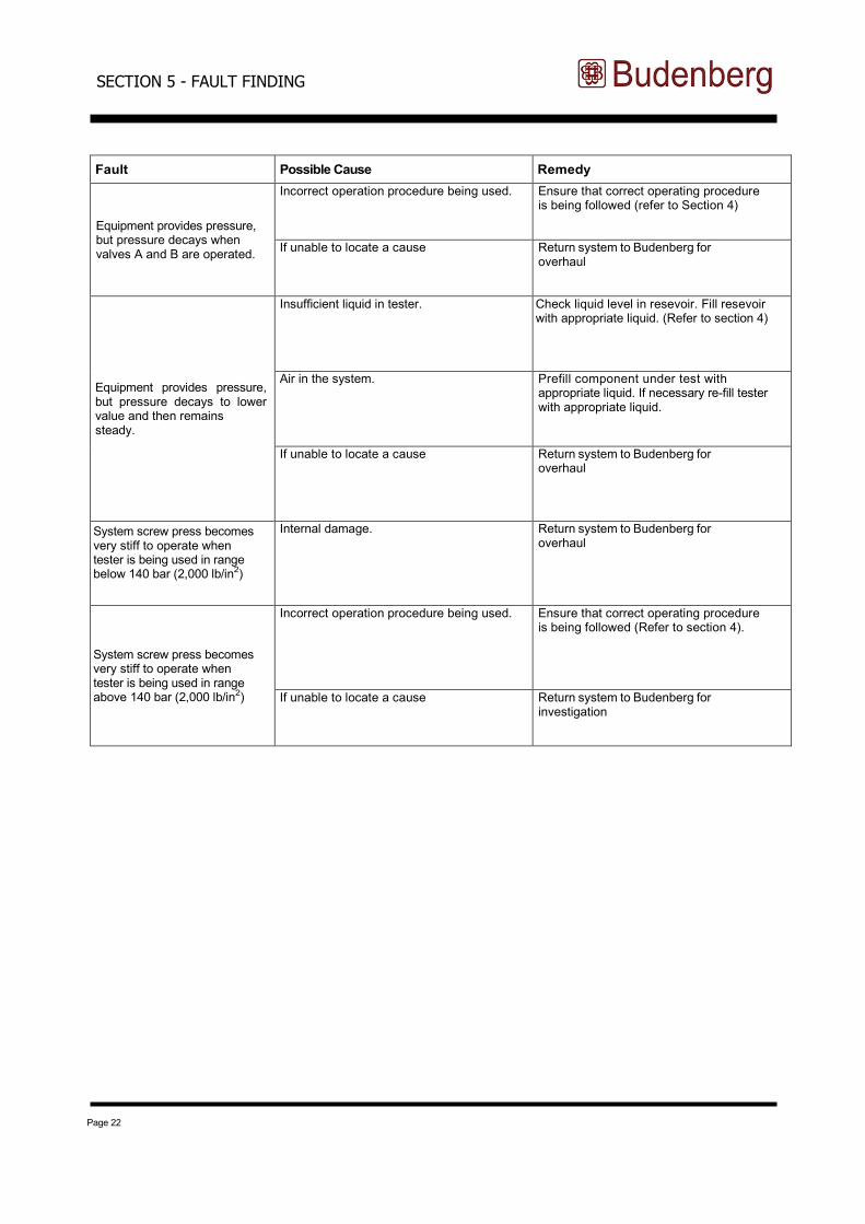
Fault Possible Cause Remedy
Equipment provides pressure, but pressure decays when valves A and B are operated.
Incorrect operation procedure being used. Ensure that correct operating procedure is being followed (refer to Section 4)
If unable to locate a cause Return system to Budenberg for overhaul
Equipment provides pressure, but pressure decays to lower value and then remains steady.
Insufficient liquid in tester. Check liquid level in resevoir. Fill resevoir with appropriate liquid. (Refer to section 4)
Air in the system. Prefill component under test with appropriate liquid. If necessary re-fill tester with appropriate liquid.
If unable to locate a cause Return system to Budenberg for overhaul
System screw press becomes very stiff to operate when tester is being used in range below 140 bar (2,000 lb/in2)
Internal damage. Return system to Budenberg for overhaul
System screw press becomes very stiff to operate when tester is being used in range above 140 bar (2,000 lb/in2)
Incorrect operation procedure being used. Ensure that correct operating procedure is being followed (Refer to section 4).
If unable to locate a cause Return system to Budenberg for investigation
SECTION 5 - FAULT FINDING
Page 23
Periodic Maintenance
6.1 CLEANING THE UNIT AND CHECKING THE LIQUID LEVELS
Cleaning the units and checking the liquid levels is the only periodic maintenance required. With normal use no further maintenance should be necessary. If required, the tester or comparator can be returned to our works for re-conditioning. If unable to return the unit, details on stripping the unit and replacing the spare parts is given in corrective maintenance. Accuracy, overhaul and re-certification is also explained in corrective maintenance.
Oil operation
Keep the tester and weights clean and free from spilt oil, wipe out the oil cups under the gauge stands as necessary. A slight leakage through the vent hole of the piston/cylinder unit is normal, but this should not be excessive unless working frequently at high pressures with a thin viscous oil. It is advisable not to dismantle the piston/cylinder unit. Do not use any cleansing solvents as they may damage the seals.
Ensure that the reservoir contains sufficient liquid to carry out any calibrations required. If necessary top up the reservoir with the same liquid that is already being used. Do not mix various types or brands of liquid in the tester.
If the oil in the tester becomes dirty, use the screw pump to flush through the clean oil with a drain screwed in the gauge stand. (The angle connection is suitable.) The screw pump should be turned fully clockwise before starting. Remove the piston/cylinder unit complete and wipe away any dirt that has accumulated on the thread on the base.
Oil free operation - Model BGH700CW
Keep the comparator clean and free from surplus water, wipe out the cups under the gauge stands as necessary. If the water in the comparator becomes contaminated then drain completely and fully dismantle ALL parts. Degrease ALL contact parts, re-assemble and fit new seals.
Ensure that the reservoir contains sufficient liquid to carry out any calibrations required. If necessary top up the reservoir with distilled or demineralised water.
SECTION 6 - PERIODIC MAINTENANCE
Page 24
Corrective Maintenance
7.1 GENERAL
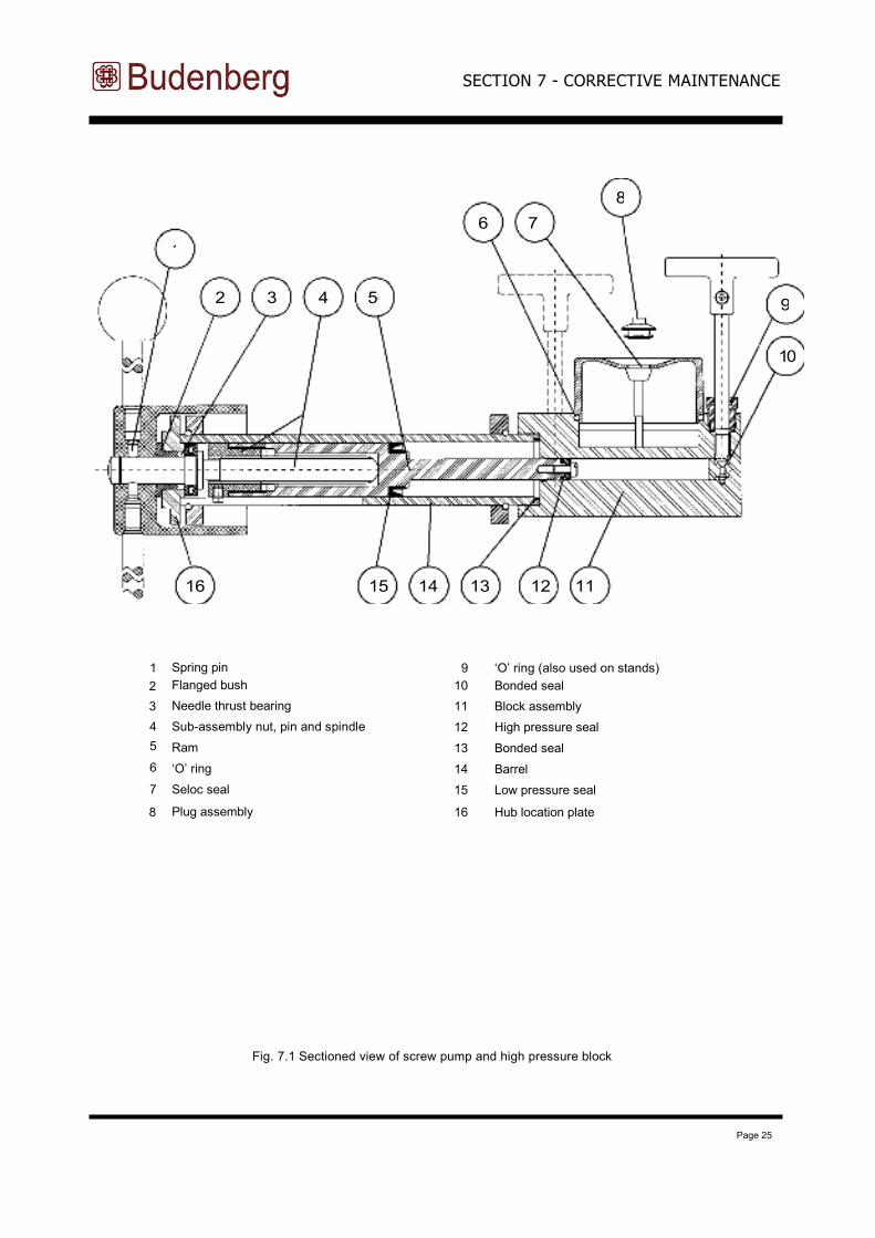
This section contains details on stripping the unit and replacing the spare parts which are listed in section 8.
The component identification numbers in brackets in each procedure refer to figure 7.1
7.2 REMOVING COVER
(1) Drain as much oil as possible from tester by winding the screw press fully clockwise and using a drain screwed in the gauge stand.
(2) Unscrew the gauge stand(s) and/or piston/cylinder unit.
(3) Remove the oil cups by levering upwards carefully.
(4)
(5)
Slacken the socket set screws using a 3 mm hexagon wrench key and remove both valve handwheels. Remove the four cover retaining screws and lift off the cover.
7.3 RESERVOIR SEALS
(1)
(2)
(3)
Unscrew two screws and remove the reservoir cover. Remove the ‘O’ ring seal (6) from the recess and the Seloc seal (7) from the screws. On replacement ensure all sealing faces are absolutely clean and do not overtighten screws.
7.4 VALVE SEALS
(1) U n s c r e w t h e g l a n d n u t . (2) Unscrew the valve spindle and remove the bonded seal.
(3) Sl i de gl an d nut of f s pi ndl e. (4) Using a suitable hooked tool remove the ‘O’ ring seal (9) from the bore of the gland nut. Renew ‘O’ ring and
bonded seal (10).
(5) On replacement ensure that ‘O’ ring is correctly located in the groove and all sealing faces are clean. Remove all burrs from spindle.
SECTION 7 - CORRECTIVE MAINTENANCE
Page 25
1 Spring pin 9 ‘O’ ring (also used on stands)
2 Flanged bush 10 Bonded seal
3 Needle thrust bearing 11 Block assembly
4 Sub-assembly nut, pin and spindle 12 High pressure seal
5 Ram 13 Bonded seal
6 ‘O’ ring 14 Barrel
7 Seloc seal 15 Low pressure seal
8 Plug assembly 16 Hub location plate
Fig. 7.1 Sectioned view of screw pump and high pressure block
SECTION 7 - CORRECTIVE MAINTENANCE
1
16 15 14 13 12 11
2 3 4 5
6 7
8
10
9
Page 26
7.5 SCREW PUMP
(1) Using a 4 mm hexagon wrench key unscrew the six socket head cap screws securing the hub locating plate. (These are positioned inside the recess in the back of the aluminium hub.)
(2) By carefully pulling the hub the complete ram assembly can now be withdrawn from the barrel. (During this operation a container is required beneath the barrel to catch any liquid.)
(3)
(4)
Unscrew the ram from the hub assembly.
NOTE: The HP seal is retained by a screw and locating ring. Check that the ram is not scored on the locating diameters.
(5) At this point the hub assembly should be checked for excess play indicating wear in the bearings and for wear in the screwed spindle and nut. If any wear is found it will be necessary to dismantle the hub assembly.
(6) Check that the bore of the barrel (14) is not badly scored or pitted. If the barrel is to be replaced or the seal (13) is to be renewed the barrel is removed from the block by unscrewing the six socket head cap screws. The seal fits in a recess in the block and should be carefully prised out, taking care not to scratch the sealing face.
(7) Check that the bore of the block assembly (11) is not badly scored or pitted. If a replacement is required this item is supplied complete with valves. The block is attached to the base by socket head cap screws.
(8) Re-assembly is a straightforward reversal of the above procedures.
NOTES:
(1) On assembly care should be taken to align the ram to prevent bending, or damage to the seals. Excessive force should not be used.
(2) The socket head cap screws are not spaced equally around the locating flanges so check hole alignment before inserting screws.
7.6 HUB ASSEMBLY
1) Unscrew the ram from the spindle. Note:- left hand thread.
2) Unsc rew the spokes f rom the hub.
3) Knock out the spring pin (1), found at the bottom of one of the tapped spoke holes in the hub, using a punch 6 mm dia. and pull off hub.
(4)
(5)
(6)
The hub locating plate and thrust bearing can now be removed from the spindle.
If the flanged bush (2) is to be renewed, it should be pressed out of the locating plate and a new one pressed in
squarely.
The thrust bearing (3) is renewed as a complete assembly.
(7) The nut, pin and spindle sub-assembly (4) can only be replaced as a matched pair. Unscrew the nut from the ram, gripping in a soft jaw vice and screw in the new nut.
(8) Assemble the thrust bearing, locating plate and hub on to the spindle lubricating with molybdenum disulphide grease.
(9) Clamp these items together to eliminate end play and re-assemble spring pin. If using new spindle drill through 6.3 mm diameter to fit spring pin (1).
(10) Lubricate the thread with molybdenum disulphide grease and screw into ram nut.
SECTION 7 - CORRECTIVE MAINTENANCE
The high pressure seal (12) and low pressure seal (15) can now be replaced.
Page 27
7.7 PISTON/CYLINDER UNIT
As the piston/cylinder unit represents a high proportion of the total value of the tester, it should always be handled with care and every effort made to keep it clean.
The piston/cylinder unit is made to extremely fine limits of accuracy and it is not advisable to dismantle it. If it is necessary to clean it, the piston and cylinder bore must be oiled immediately, in order to protect the high grade finish. Should the unit become damaged it should be returned complete for replacement or repair. Parts from different units are not inter-changeable as they have to be weighed and evaluated as a whole.
The serial number of the piston/cylinder unit appears in the certificate of accuracy and is marked on the body of the unit. This number, as well as the tester serial number should always be quoted in correspondence concerning the piston/cylinder unit.
The piston/cylinder connections should be blanked if it is removed from the tester. If the unit is taken off for any reason it should be stored upside-down resting on the weight carrier.
This covers stripping the unit to enable simple repairs and the fitting of recommended spare parts to be carried out.
7.8 FACTORY OVERHAUL AND RE-CERTIFICATION OF DEAD-WEIGHT TESTERS MAINTENANCE OF
ACCURACY
The accuracy of a dead-weight tester depends primarily on the effective area of the piston unit and on the weights applied to the piston. The effective area of the piston unit can be affected by wear of the unit. This is generally caused by contamination of the oil in the tester by foreign matter from instruments being calibrated, by water, or chemicals from instruments, or by rust or corrosion caused by contaminants.
Weights are made of austenitic stainless steel which are entirely stable. In the past we have supplied testers with specially treated cast iron weights and martensitic stainless steel weights. Whilst these earlier weights were entirely suitable under normal conditions of use, they may exhibit some instability of mass if left in contact with damp materials or water.
NEED OR OVERHAUL AND RE-CERTIFICATION
We recommend that the tester be returned to us for overhaul and re-certification at any time if when used in accordance
with instructions:
(a ) The p i s ton does no t sp in f ree l y .
(b ) The rate of fall of the piston is appreciably greater than when new and makes use of the tester difficult.
( c ) The weights are damaged or seriously corroded.
(d ) The tester cannot be made to operate satisfactorily due to wear or damage to pump piping or valves which cannot be rectified by the user.
Many testers are used for calibration of instruments with an expected accuracy of 1, 0.5 or 0.25%. Such testers need not be sent back frequently for overhaul and re-certification and provided they are working well can be trusted for many years. Under these circumstances an interval of five years might be appropriate between overhauls.
When high accuracy is required of dead-weight testers the testers should be returned for overhaul and re-certification more frequently. The actual period will depend on how a tester is used. A tester kept in a laboratory and carefully used might need to be returned every 2 to 3 years. A tester carried around from site to site and used for calibrating high accuracy gauges or transducers from industrial process plant or for measuring pressures directly might well need to be returned at intervals of less than a year.
The actual period between overhaul and re-certification should be fixed by the user in the light of the above comments taking into account the requirements of any inspection authority which might be involved.
IDENTIFICATION OF WEIGHTS
All weight sets supplied with a dead-weight tester have allocated, and are marked with, a weight set number. Additionally, if users wish to ensure that only specific weights sets are used with an individual dead-weight tester or piston and cylinder unit, then the serial number of the tester, and/or piston cylinder unit may also be marked on the main weights. Regrettably due to their size, increment weights can only be marked with the serial number of a piston and cylinder unit.
SECTION 7 - CORRECTIVE MAINTENANCE
Page 28
OVERHAUL AND RE-CERTIFICATION
To provide the best possible service, testers should be returned as complete units comprising the base, the piston and cylinder unit, and all weights. Users may at their discretion elect to service the base themselves and only return the piston and cylinder unit with weights for overhaul. In such instances, certification issued after overhaul can only refer to the piston and cylinder and weight set numbers and not to the base to which they were originally fitted.
Tester bases will be stripped, all pipework cleaned, all seals replaced, worn components replaced where desirable and all reassembled and tested.
The weights will all be checked and brought to within original limits if possible. If one or two weights are missing or beyond economic repair they will be replaced. If more are missing/beyond economic repair customers instructions will be sought.
The piston unit will be checked for accuracy and sensitivity. If it is not satisfactory for any reason a quotation will be submitted for a replacement unit.
A new certificate of accuracy will be issued for each overhauled tester. Unless otherwise instructed on order when there has been a slight change in area of the piston unit the certificate will reflect this; the accuracy will not be affected by more than 0.03%. For example the certificate of accuracy of an overhauled tester might show that the error does not exceed 0.05% when the original certificate shows that the error did not exceed 0.02%.
We can provide UKAS certificates for overhauled testers and also for testers in good condition whether or not of our manufacture. Details will be supplied on request.
ORDERING AND PRICING
No tester will be overhauled if it is not economic to do so. By far the most expensive component likely to need replacement is the piston unit; this unit will not be replaced unless customers approval has been obtained.
When customers ordering procedure does not allow an open order to be placed we quote a basic price for the overhaul and re-certification of particular model of tester. This assumes that the tester and weights are in good condition and covers stripping, cleaning of pipework, replacement of seals, re-assembly and testing, checking of weights and of piston unit. The basic price covers our certificate of accuracy in the typical form shown in our catalogue. Customers requiring
a more detailed certificate of calibration should state this on their order.
Any additional work required will be carried out and will be charged on a time and material basis. These additional charges will be detailed on the invoice but the piston units will not be replaced without customers approval. Orders should therefore state basic quoted price “plus additional service and replacement parts as required”.
SECTION 7 - CORRECTIVE MAINTENANCE
Page 29
Spare Parts
8.1 SPARE PARTS LIST
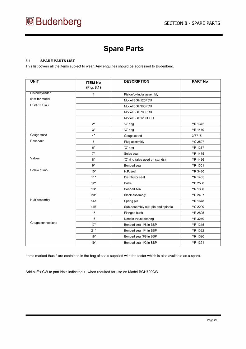
This list covers all the items subject to wear. Any enquiries should be addressed to Budenberg.
UNIT ITEM No
(Fig. 8.1)
DESCRIPTION PART No
Piston/cylinder
(Not for model
BGH700CW)
Gauge stand
Reservoir
Valves
Screw pump
Hub assembly
Gauge connections
1 Piston/cylinder assembly
Model BGH120PCU
Model BGH300PCU
Model BGH700PCU
Model BGH1200PCU
2* ‘O’ ring YR 1372
3* ‘O’ ring YR 1440
4+ Gauge stand 3/3715
5 Plug assembly YC 2597
6* ‘O’ ring YR 1387
7* Seloc seal YR 1475
8* ‘O’ ring (also used on stands) YR 1436
9* Bonded seal YR 1351
10* H.P. seal YR 3430
11* Distributor seal YR 1455
12* Barrel YC 2530
13* Bonded seal YR 1330
20* Block assembly YC 2497
14A Spring pin YR 1678
14B Sub-assembly nut, pin and spindle YC 2290
15 Flanged bush YR 2825
16 Needle thrust bearing YR 3240
17* Bonded seal 1/8 in BSP YR 1315
21* Bonded seal 1/4 in BSP YR 1352
18* Bonded seal 3/8 in BSP YR 1320
19* Bonded seal 1/2 in BSP YR 1321
Items marked thus * are contained in the bag of seals supplied with the tester which is also available as a spare.
Add suffix CW to part No’s indicated +, when required for use on Model BGH700CW.
SECTION 8 - SPARE PARTS
Page 30
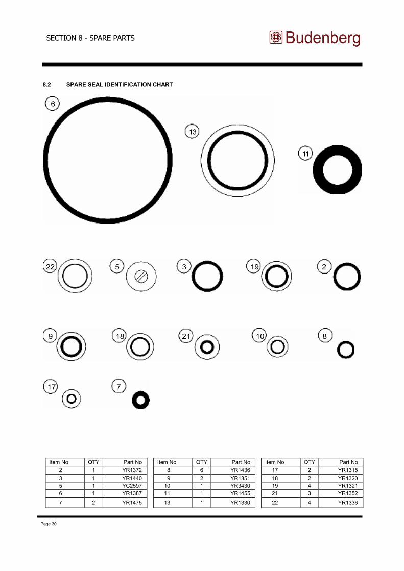
8.2 SPARE SEAL IDENTIFICATION CHART
SECTION 8 - SPARE PARTS
11
6
13
22 5 3 19 2
9 18 21 10 8
17 7
Item No QTY Part No
2 1 YR1372
3 1 YR1440
5 1 YC2597
6 1 YR1387
7 2 YR1475
Item No QTY Part No
8 6 YR1436
9 2 YR1351
10 1 YR3430
11 1 YR1455
13 1 YR1330
Item No QTY Part No
17 2 YR1315
18 2 YR1320
19 4 YR132121 3 YR1352
22 4 YR1336
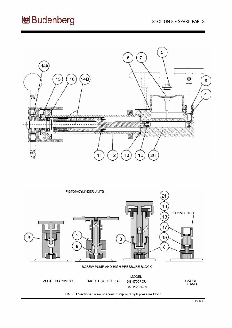
Page 31
SCREW PUMP AND HIGH PRESSURE BLOCK
MODEL BGH120PCU MODEL BGH300PCU GAUGE
MODEL
BGH700PCU,
BGH1200PCUSTAND
FIG. 8.1 Sectioned view of screw pump and high pressure block
SECTION 8 - SPARE PARTS
14A
15 16 14B
11 12 13 10 20
6 7
5
9
8
3
PISTON/CYLINDER UNITS
8
23
21
19
19
18
17
8
CONNECTION
Page 32
8.3 ORDERING SPARES
1 ) Tester model No. (on front of this manual)
2) Tester serial No. (on nameplate)
3) Description of part. See spare parts list.
Whilst every effort is made to ensure that the correct parts are supplied, this cannot be guaranteed unless full information
is given.
Ordering spares can be carried out from our service department at the following addresses:
EUROPE AND AMERICAS
Budenberg Customer Services,
4 Gilchrist Road, Northbank IndustrialEstate, Irlam, Manchester M44 5AY United Kingdomwww.budenberg.co.uk
Tel: +44 (0)161 777 7300Fax: +44 (0)161 777 7301Email: [email protected]
SECTION 8 - SPARE PARTS
FAR EAST
Budenberg Gauge Pte Ltd, 18 Sin Ming Lane#07-12 Midview City573960Singaporewww.budenberg-gauge.asia
INDIA
Budenberg Gauge Pvt Ltd,299-300, IInd Main Road,Nehru Nagar , Old Mahabalipuram Road ( OMR),Chennai - 600 096,Tamil Nadu , Indiawww.budenberg-gauge.in
MIDDLE EAST & AFRICA
Budenberg MEA FZC Office No. 217, Splash Building PO Box 18980, Al Qusais Dubai, United Arab Emirates web: www.budenbergmea.com
Tel: +971 4 2511670 Fax: +971 4 2511671 Email: [email protected]
Tel: +91 44 24541074Fax: +91 44 24541075Email: [email protected]
Tel : +65 3158 5419Email: [email protected]
When ordering spares or making enquiries always give:
Page 33
Optional Extras
9.1 MODEL 29 POWER ROTATION UNIT
9.2 OIL FREE TESTING
Model 38 and 25 oil seals are available for use during oil free testing. The seals have a synthetic rubber sac which separates the oil in the tester from the liquid on which the gauge is to be tested. The model 38 oil seal can be used on any tester up to a maximum working pressure of 700 bar or 10000 Ib/in2. The model 25 oil seal is similar to above but with smaller displacement and for use up to 1200 bar or 16000 Ib/in2.
9.3 FINE INCREMENT WEIGHTS
9.4 MODEL 27 - TWO GAUGE STAND
This is available for the testing of two gauges simultaneously.
9.5 MODEL 360 BASE
A Model 360 oil dead-weight pressure balance incorporating the piston unit and weights used in the Model BGH series dead-weight testers. This balance enables an operator to calibrate a transducer/pressure gauge at two different pressures without adding/removing any weights, thus speeding up the calibration process.
9.6 MODEL 433 AND 436 CARRRYING CASES
These cases are designed for transporting the dead-weight tester or weights to site and are suitable for use by commissioning teams on large projects such as chemical plants. They enable the complete calibrating system to be conveniently transported without the loss of items. The provision of a can of oil will be found particularly useful on remote locations.
9.7 MODEL 437 WEIGHT STORAGE CASE
These cases are designed for storing of weights in the laboratory or workshop and would be ideal in any standards room or area where equipment needs to be stored when not in use. They also keep the weights set together to prevent weights going astray and protect them from accidental damage.
9.8 UKAS CERTIFICATION
All testers are available with certification of calibration on pressure, also certification of effective area and mass of the piston unit, also of the mass of the weights.Consult your local distributor for advice.
SECTION 9 - OPTIONAL EXTRAS
Extra weight sets to give fine increments of pressure less than those normally supplied with the tester can be supplied for use with all piston/cylinder units.
The model 29 power rotation units consist of a motor rotating the weights at a constant speed to save operator fatigue during prolonged testing. The model 29 is used with model BGH700PCU and BGH1200PCU testers only.