Embed Size (px)
Citation preview
http://repository.osakafu-u.ac.jp/dspace/
TitleBuckling Strength of Stiffened Plates Containing One Longitudinal or Tr
ansverse Girder under Compression
Author(s) Okada, Hiroo; Kitaura, Ken'ichi; Fukumoto, Yoshio
Editor(s)
CitationBulletin of University of Osaka Prefecture. Series A, Engineering and nat
ural sciences. 1972, 20(2), p.287-306
Issue Date 1972-03-31
URL http://hdl.handle.net/10466/8188
Rights
287
Buckling Strength of Stiffened Plates Containing
One Longitudinal or Transverse Girder
under Compression
Hiroo OKADA," Ken-ichi KiTAuRA" and Yoshio FuKuMoTo"
'
(Received November 15, 1971)
The buckling strength of stiffened plates containing one longitudinal or transverse
girder under compression, is discussed in this paper. The stffened plate,is idealized by
an equivarent orthotropic plate. Non-dimensional design tab!e giving the critical stress for
the symmetric buck1ing of the systern are presented for different values of virtual aspect
ratio, the effective torsional rigidity of stiffened plate and girder characteristics. And the
'curves of- the limiting value 7o corresponding to the minimum value of the flexural rigidity
of the girder wbich just guarantees antisymmetric buckling of the system are' also presented.
At the same time, the effective breadth of the stiffened plate which cooperates with the
girder and is necessary in the calculation of the flexural rigidity of the girder, is also
calculated.
1. Introduction
This study is concern'ed with the basic structural element used in ship and marine
structures, that is, the plate-stiffener combination. In this place, we consider the elastic
strength of a longitudinally compressed rectangular plate which is reinforced by orthogonally
intersecting stiffeners and one longitudinal girder or transverse girder on the c3nter line.
The plate reinforced by orthogonally lntersecting stiffeners is idealized by an equivarent
orthotropic plate.
In this plate-stiffener combination system idealized by the equivarent orthotropic plate
system, there are two typical forms of the displacement of the buckled system according to
the magnitude of the flexural rigidity of the girder; (1) a symmetric configuration with the
deflected girder, (2) an antisymmetric configuration where the girder remains, straight.
The buckled plate has in the latter case nodal line coinciding with the axis of the girder.
<It is assumed that the local buckling of the girder will never occur.)
In general, when the flexural rigidity EI of the girder is small, the symmetric displace-
ment form in which the girder defiects with the orthotropic ptate wil1 occur. The antisyrn-
metric displacement form will occur when the flexural rigidity EI is larger than a certain
value Ek. The critical stress in this case does not depend on EL but it is consistent with
that of a simply supported orthotropic plate of a half width (for longitudinal girder) or a
half length (for transverse girder). The bucklin.a load of the orthotropic plate containing
the girder, reaches in this case its maximum values. At the fiexural rigidity E4, both
configurations are equally possible.
In 2-1. or 2-2., we study the symmetric buck}ing for values EI<Ek and determine
* Department of Naval Architecture, College of Engineering.
t
288 H. OKADA, K. KiTAuRA and Y. FuKuMoTo
the limiting value E4 of the flexural rtgidity of the girder which just guarantees the anti-
symmetric buckling of the orthotropic plate containing a longitudinal girder or transverse
girder. And in 2-3., for the calculation of the flexural rigidity EI of the girder in such
cases as the girder is attached to one side of the plate and is unsymmetry with respect to
the middle plane of the plate, the effective bredth of the orthotropic plate which cooperates
with girder is calculated. In 3., the practical application method of the theory on the
orthotropic plate system to the plate-stiffener combination system, is shown.
2. Theory on Orthotropic PIate
2-1. Sirnply supported orthotropic plates having one longitudinal girder on the
center line.
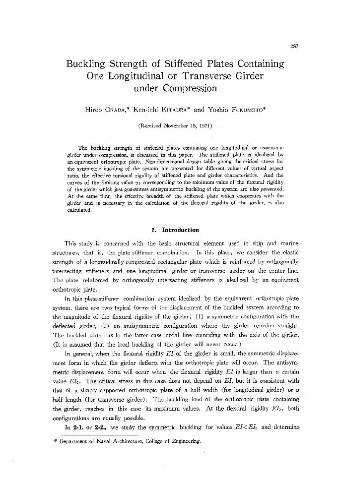
Consider a simply supported rectangular orthotropic plate of length a, width b, and
thickness t, which is reinforced by' a longitudinal girder on the center line (see Fig. 1(a)).
The area of the cross section of the girder is A, and its moment of inertia L It is assumed.
that the center line of the girder lies in the middle plane of the plate, and the moment of
inertia L therefore, refers to the axis of the' girder in this plane. The torsional rigidity of
the girder is regarded as srna11 and will be neglected. We select a system of coordinates
x,N,2 having its origin O in the center of the left edge of the plate. The plate is loaded
by a uniformly distributed load pt acting on the edges x-O and x==a. It is assumed that
the girder is fixed to the plate and has the same compressive stress p as the plate.
p
-`'1c"
o girder(A,l)
elcv
a
1,
p
x・-o;
t
l
z
y (a) (b) (c) Fig. 1 Buckling of the sirpp!y supported orthotropic plate having one longitudinal girder
on the center line.
' As stated in 1., a symmetric configuration with defiected girder (Fig. 1(b)) will occur
when the flexural rigidity EI is small, and an antisymmetric configuration where girder
remains straight (Fig.' 1(c)) will occur when EI is larger than a certain value Ek.
In tihis place, we investigate the symmetric configtiration of the buckled plate in order'
to derive the condition of instability. The relations between the stress and strain components'
for the orthotropic plate can be represented by the following equation in this coordinate
system ;
:jl=a-l.,,) [v.ikv "erEE,n 8 [,EI ' (,,
T!,vJ <O O G(1-vvavv) <rxv
Buckling Strength of St4fiZintg{.rdlZterateusnttorntctStttsesOt;oenLongitudinal or 7?ansverse 2sg
where vx Ev=vv Ele.Requiring equilibrium of forces in the 2 direction, the equilib;ium equation can be written
/in the form;
a4wl 04wl 04wi 02wl Dx ox4 ÷2H ox2dy2 +Dv obl4 +Pt ax2 =O (2)
7where wi==the deflection of the lower half of the plate, (or)O)
Das=Ext3/{12(1-vxvw)}, Dv==Evt3/{12(1-vxvv)}
2H"= Gt3/3+ vx Dv +vv Dx ・
The deflection wi must satisfy the Eq. (2) and the following boundary conditions;
02w! ==O for x-O and x== a. (3) Wl "" O ax2
We take the solution of Eq. (2) in the form
nrc wi "= Y(or)sin .x (4)'then, Eq. (2) requires that Y(pu) takes a form as
Y( ov) -Ci coshuiy+C2 sinhury+C3 cos u2 ov+C4 sin u2 pt (5)
where ui b = (nn/cre) Vn + Vij2-+-kcr,2/n2 - 1
u2 b == (nz/cro) AV! - rp + Vv2 + Kcr,2/n2 - 1
ao-(a/b)VDv/D., rp-"/VD.Dy (6) K -:: ptb2/(z2 VD. Dv )
Ci to C4=integral constants.
'The four constants Ci to C4 in Eq. (5) will be determined from the following boundary
・conditions ;
w,-=-l2S-tt,-i--o for bl=-b/2 (7)
OWi 'obl .:=O for ov-O (8)
2i-Q2-q for rv-=O (9) in which q represents the vertical forces per unit lensgth acting on the girder.
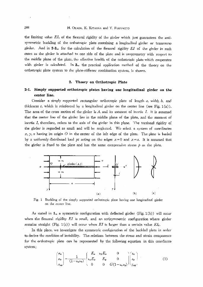
By 2i and Q2 we denote the equivarent shearing forces per unit length in the plates
adiace.nt to the girder (see Fig. 2). The load g is
q=2i-Q2
==[-{Dv Oillt£,{Li +(H+2Dxv) 60.3 abI }+{Dv Oo3y¥X2 +(H+2Dcav) oO.' l{I)}],., (a)
where 2zl2=the deflections of the upper half of the plate, (or¥O)
' tt ' DxvfGe3/12.'"
s
290 H. OKADA, K. KiTAuRA and Y. FuKuMoTo
Oy
g>y'i2l"(i/.
Q2 Q,
2
Fig. 2 The vertical forces acting on the girder.
Because of the symmetry, we have the relations ,
02wl 02xv2 03wl 63xv2 ax2-== ax2, dy3 =- dy3' for or=O (b)and therefore
g== -2Dv[ 6iii/) IL],.,' (c)
Taking account of the axial load pA in the girder, the differential equation for its deflection
w is
EIOo`.w,+pA-g/th'-v,--q. (lo)
Considering Eq. (c) and xu= [wi]v.o, Eq. (9) is
[EI Oo`,:,Ii+pA Oo2,:,Si +2Dw Oii/I):i ],.,=o・ (11)
Introducing the solution (4), (5) into the boundary conditions (7), (8) and (11), we
arrived at the four homogeneous equations for the constants Ci to C4. The determinant
of the system of equations furnishes the stability condition for the symmetric mode of
buckling;
2(ao/nn)`(ui2b2+u22b2)
-{ tanhXtb/2) tan(.t,2bb/2) }{r-K6(a,/n)2} =to (i2)
'where
r"Ell(Dnb), 6=A/(bt). ' ' (13)The coethcient r is the ratio of the flexural rigidity of the girder to that of the plate of
width b in the x direction, and G is the ratio of the cross-sectional area of the girder to
the area bt of the plate.
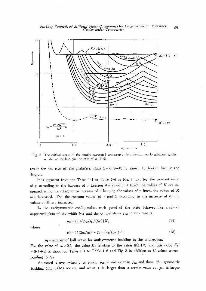
The critical stress pcs for the symmetric buckling (Fig. 1(b)) is given by the minimum
value of p with respect to the number n of half waves in Eq. (12). The numerical results
are shown in Table 1-1 to Table 1-6 by using the plate factor K in Eq. (6), namely
IIle,- {T2Va7ii 75:7D, /(tb2)}K.
As an example, the values of K for the effective torsional rigidity coeMcient n= O.6 are
plotted against the virtual asFect ratio cre for Various values of r and 6 in Fig. 3. And the
TK
15
10
Buckling Strength of Stij7ZinedGir
Plates Containing One Longitudinal or 7'ransverseder under Compression
lllxtl/NNNtN -tN(KoCi=>=AIo)
).--N.-7NN2s,s=o,l5lt111t,
".22xX!02xx'O"r-.
y,o.oo
diXXO.05O.10o0・i5・?0
t1,1tss't,sNN
0・000・0s/"Z'g・p
n=1 n----2
NNNNN...A.7 zso,o;"o-.-.--N-i.--
'-d------A----
i
,,,-"2 :tl'lt2!TK
ep==O.6
291
KS =" 8(1+ n)
5
2(1+n)
o
ae - Fig. 3 The critical stress of the simply supported orthotropic plate having one longitudinal girder
on the center line (in the case of ny=O.6).
result for the case of the girderless plate (r=:O, O=O) is shown by broken line in the
diagram.
It is apparent from the Table 1-1 to Table 1-6 or Fig. 3 that for the constant value
of rp, according to the increase of r keeping the value of S fixed, the values of K are in-
creased, while according to the increase of a keeping the values of r fixed, the values of K
are decreased. For the constant values of r and 6, according to the increase of rp, the
values of K are increased.
In the antisymmetric configuration, each panel of the plate behaves l!ke a simply
supported plate of the width b/2 and the criticai stress pca in this case is
Pca =" {z2AViD.Dv/(tb2)}Ko (14) 'where
Ko=-4[(2ao/ni)2+2ny+{ni/(2cro)}2] (15)
n!==number of half wave for antisymmetric buckling in the x direction.
For the value of ao>O.5, the value Ko is clase to the value 8(1+rp) and this value Ko'
==8(1+rp) is shown in Table 1-1 to Tabie 1-6 and Fig. 3 in addition to K values corres-
ponding to Pcs・
As stated above, when r is small, pcs is srnaller than pca and then, the synmietric
buckling (Fig. 1(b)) occurs, and when r is larger than a certain value ro,pca is larger
292
Theon the
Then-o. o,
'H.' OKADA, K. KiTAuRA and Y. FuKuMoTo -
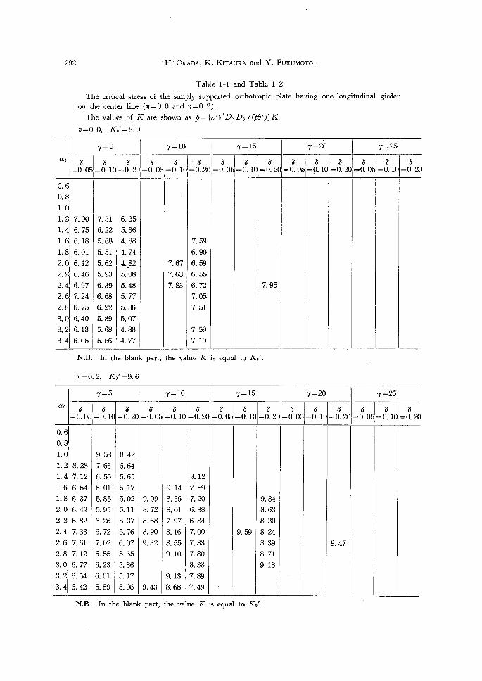
Table 1-1 and Table 1-2
critical stress of the simply supported orthotropic plate having
oenter line (n=O.O and ny==O.2).
values of K are shown as p={x21/D.Dv /(tb2)}K.
Ke'=8. 0
one longitudinal girder
ao
7=5
s=O. 05
6=O. 101
B==O. 20
7=10
s=O. 05
s== O. 10
=o8. 2o
7=15
t
O. 6
o. 81
1. 0ii
1. 2i
1. 4
IIg:I:2. 4:2. 6I
2. 8
・gl:l
3. 41
7. 90
6. 75
6. 18
6. 01
6. 12
6. 46
6. 97
7. 24
6. 75
6. 40
6. 18
6. 05
7. 31
6. 22
5. 68
5. 51
5. 62
5. 93
6. 39
6. 68
6. 22
5. 89
5. 68
5. 56
6. 35
5. 36
4. 88
4. 74
4. 82
.5. 08
5. 48
5. 77
5. 36
5. 07
4.88
4. 77,
' 4 l
s-=O. 05
7. 67
7. 63
7. 83
7. 59
6. 90
6. 59
6. 55
6. 72
7. 05
7. 51
7. 59
7. 10
s==O. 10
s=O. 20
7. 95
or-20
L!= 8. os s==O. 10 -t
s-O. 2Q
7;25
L
s== O. 05
8
O, 10 s-O. 20
N.B. In
"-O. 2,
the blank
Ko'=9. 6
part, the value K is equal to Ko'.
ao
O. 6
O. 8
1. 0
L2L4L61.8
2.0
2. 2
2. 4
2.6
2. 8
3. 0
3. 2
3. 4
7=5
so. 05L
5=O. 10
8. 28
7. 12
6. 54
6. 37
6. 49
6. 82
7. 33
7. 61
7. 12
6. 77
6. 54
6. 42
9. 58
7. 66
6. 55
6. 01
5. 85
5. 95
6. 26
6. 72
7. 02
6. 55
6. 23
6. 01
5. 89
s=O. 20
8. 42
6. 64
5. 65
5. 17
5. 02
5. 11
5. 37
s. 76
6. 07
5. 65
5. 36
5. 17
5. os
7=10
s=O. 05
9. 09
8. 72
8. 68
8. 90
9. 32
9. 43
s=O. 10
9. 14
8. 36
8. 01
7. 97
8. 16
8. 55
9. 10
9. 13
8. 68
s=O. 20
9. 12
7. 89
Z 20
6. 88
6. 84
7. 00
7. 33
7. 80
8. 38
7. 89
7. 49
7-15
8=O. 05
s
=O. 10
9. 59
8=-O. 20
9. 34
8. 63
8. 30
8. 24
8. 39
8. 71
9. 18
7=20
s=- O. 05
/
s=O. 10
s=O. 20
9. 47
7=25
s= O. 05
s==O. 10
s==O. 20
N.B. In the blank part, the value K is equal to Ko'.
Buckling Strength of Stzfantsg..dP,Z9e.s.dC,o.ntsStrzg,g?,:..e.LOngitUdinal
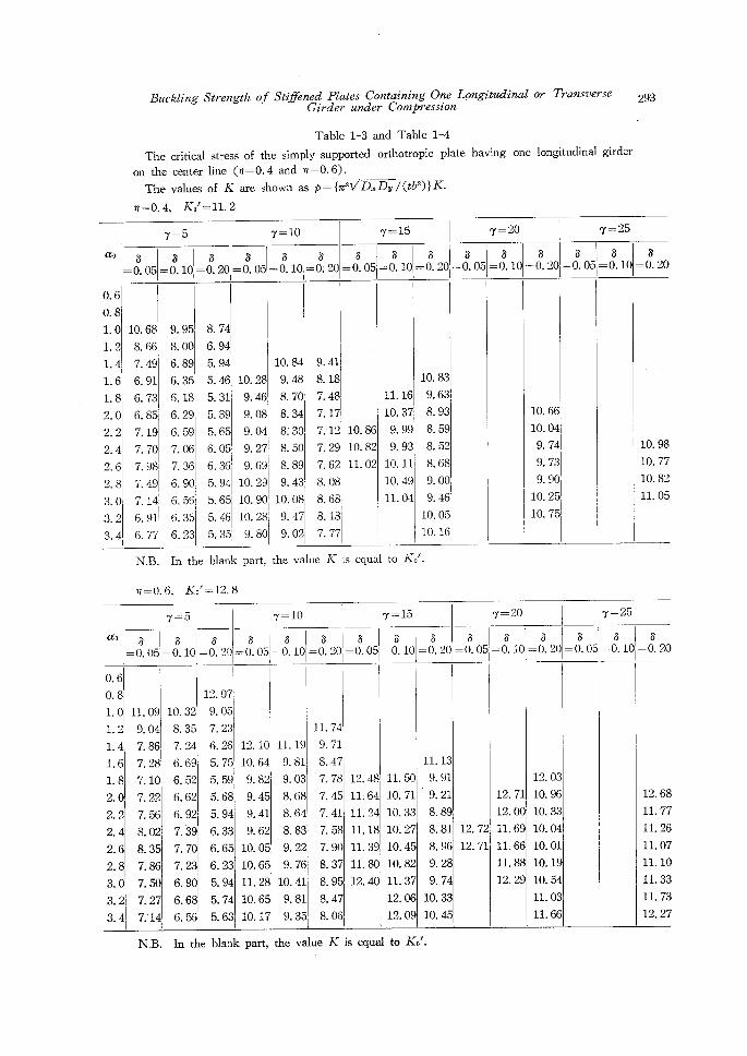
Table 1-3 and Table 1-4
The critical stress of the simply supported ・orthotropic plate having one
on the center line (n=O.4 and "=O.6).
The values of K are shown as p={T2V'D.Dv/(tb2)}K.
op;=O.4, Ko"==ll.2
or l}ansverse
longitudinal girder
293
ao
7=5 7--10
8=O. 05
O.6
O. 8
LO1. 2
1.4
1.6
1. 8
2. 0・
2. 2
2. 4
2.6
2. 8
3. 0・
3.2
3.4 l
s=O. 10
, S8=O. 20 =O. 05 l
10. 68
8. 66
7. 49
6. 91
6. 73
6. 85'
7. 19
7. 70
7. 98i
7. 49I
7. 14
6. 91
6. 77
9. 95
8. 00
6. 89
6. 35
6. 18
6. 29
6. 59 17. 06
7. 36
6. 90/
I6. 56i
l6. 35
6. 23
8. 74
6. 94
5. 94
5. 46
5. 31
5. 39
5. 65
6. 051
I6. 36i
5. 94
5. 65!
s. 46i
s. 351
6==O. 10
s== O: 20
7=-15
8-O. 051
B= O. 10
7=20
s
O. 20・
s-= O. 05
s-O. 10
8-O. 20
7==25
10. 28
9. 46
9. 08
9. 04, I 9. 271
g. 6gl
10. 29
10. 90/ 110. 28I
l 9. 80
10. 84
9. 48
8. 70
8. 34
8i 30
8. 50
8. 89
9. 43,
lo. 08i
9. 47'
9. 02・
[9. 41'
8.' 18
7. 48 I7. 17
7.-12 10.86
7. 29 10. 82
7. 621 11. 02
I8. 08,
8. 681
I8. 18I 17. 77'
11. 16
10. 37
9. 99
9. 93
10. 11
10. 49
11. 04
1
1
10. 83
9. 63
8. 93
8. 59
8. 52
8. 68
9. 00
9. 46
10. 05
10. 16
'
t
L
s-O. 05
10. 66
10. 04
9. 74
9. 73
9. 90
10. 25
10. 75
s-O. 10
/
1/
I:
s=O. 20
10. 98
10. 77
10. 82
11. 05
NB. In
"7.0.6,
the blank part,
Ko' =- 12. 8
the value K is equal to Ko'.
7==5
aoi
s-O. 05 I
s-O. 10
O.6
O. 8
1.0
1. 2
1.4
1.6
1. 8
2. 0
2. 2
2. 4
2. 6
2. 8
3. 0
3. 2
3. 4
s-O. 20
7-10tl
8==- O. 05
' s[s-O. 101-O. 20 1
1i
7-15
s-- O. 05
s[-O. Io
s-0. 20
7-20
l
11. 09
9. 04
7. 86 7. 2sl
7. 10
7. 22
7. 56
8. 02
8. 35
7. 86
7. 50
7. 27
7.'14i
10. 32
8. 35,
7. 24
6. 69
6. 52
6. 62
6. 92
7. 3g
7. 70
7. 23
6. 90
6. 68
6. 55
12. 07 f 9. 05
7. 23'
6. 26
5. 75
5. 59
5. 68
5. 94
6. 33
6.65
6. 23
5. 94
5. 74
5. 63
12. 10
10. 64
9. 82
9. 45
9. 41
9. 62
10. 05
10. 65
11. 28
10. 65
10. 17
1
IL 19
9. 81
9. 03
8. 68
8. 64
8. 83
9. 22
9.・76
10. 41
9. 81
9. 35L
11. 74
9. 71
8. 47
7. 78
7. 45
7. 41
7. 58
7. 90
8. 37
8. 95・
8. 47
8. 06
12. 48
11: 64
11. 24
11.18
11. 39
11. 80
12. 40・
L S6 s-O. 051-O. 10i-O. 20
11. 50・
10. 71
10. 33
10. 27
10. 45
10. 82
11, 37
12. 06
12. 09
IL 13
9. 91
9. 21
8. 89
8. 81
8. 96
9. 28
9. 74
10. 33
10. 45
12. 72.
12. 71
12. 71
12. 00
11. 69
11. 66
11. 88
12. 29
12. 03
10. 96
10. 33
10. 04
10. 01
10. 19
10. 54
11. 03
11. 66
7-=25
s-O. 05
s-o.
s101=O. 20
'
12. 68
11. 77
11. 26
11. 07
11.10
11. 33
11. 73
12. 27
NB. In the blank part, the value K is equal to Ko'.
294 H. OKADA, K. KITAuRA and Y. FuKuMoTo
Theon the
The
ny=O. 8,
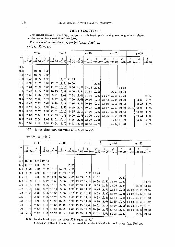
Table 1-5 and Table 1-6
critical stress of the simply supported orthotropic plate
center line (n==O.8 and n==1.0).
values of K are shown as p== {x2VDcaDv/(tb2)}K.
Ko'=14. 4
having one longitudunal girder
ao
O. 6
O. 8
1. 0
1. 2
1. 4
1. 6
1. 8
2. 0
2. 2
2.4
2. 6
2. 8
3. 0
3. 2
3. 4
7==5
s==o.od s==O. 10
11. 48
9. 40
8. 22
7. 64
7. 47
7. 58
7. 92
8. 43
8. 72
8, 22
7. 87
7. 64
7. 51
13. 83
10. 69
8. 69
7. 57
7. 02
6. 85
6. 95
7. 26
7. 72
8. 04
7. 57
7. 24
7. 04
6. 90
s== O. 20
12. tgi
9. 36
7. 53
6. 52
6. 03
5. 88
5. 96
6. 22
6. 64
6. 94
6. 52
6. 2216. 031
5. 94
r==!o
ss=- O. 051 -O.
101 =- S. 20
7== 15
l
s=O. 05
12. 47
11. 02
10. 19
9. 81
9. 77
9. 99
lo. e
11. 01
11. 65
11. 01
10. 541
13. 75
11. 54
10. 15
-9. 37
9. 01
8. 97
9. 17
9. 55
10. 10
10. 73
10. 15
9. 70
12. 05
10. oo
8. 76
8. 06
7. 74
7. 70
7. 86
8. 19
8. 65
9. 20
8. 76
8. 33
14. 27
12. 84
12. 01
11. 61
11. 54
11. 75
12. 17
12. 76
13. 51
13. 48
s==O. 10
s=O. 20
13. 19
11. 83
11. 04
10. 66
10. 60
10. 78
11. 16
11. 70
12. 39
12. 43
13. 35
11. 42
10. 21
9. 50
9. 15
9. 10
9. 25
9. 57
10. 03
10. 61
10. 74
7=20
s=O. 05
14. 17
13. 43
13. 09
13. 07
13. 31
13. 76
s=T. O. 10
14. 26
13. 04
12. 34
12. 02
12. 00
12. 21
12. 62
13. 20
13. 92
s=O. 20
14. 02
12. 32
11. 24
10. 62
10. 33
10. 30
10. 48
10. 82
11. 32
11. 93
7=25= o8. osl
s=O. 10
14. 39
14. 01
13. 43
13. 21
13. 26
13. 54
14. 01
8=- O. 20
12. 94
12. 06
11. 55
IL 35
11. 39
11. 62
12. 01
12. 55
N.B, In the
op=1. 0,
blank part,
Ko'=16.0
the value K is equal to Ko'.
ao
O. 6
O.8
1.0
1. 2
1. 4
L6L82. 0
2. 2
2. 4
2. 6
2. 8
3. 0
3. 2
3. 4
7-5
B=O. 05
15. 08
11. 87
9. 78
8. 59
8. 01
7. 83
Z958. 28
8. 79
9. 09
8. 59
8. 24
8. oo
7. 87
s=O. 10
14. 28
11. 05
9. 04,
7. 90
7. 35
7. 19
7. 29
7. 60
8. os
8. 38
7. 91
7. 57
7. 35
7. 23
s== O. 20
12. 84 ! 9. 67'
7. 82
6. 81
6. 32
6. 17
6. 25
6. 51
6. 90
7. 23
6. 81
6. 51
6. 32
6. 21
7=-10
s== O. 05
15. 16
12. 86
11. 39
10. 56
10. 18
10. 14
10. 35
10. 78
11. 38
12. 02
IL 39
10. 90
s=O. 10
14. 12
11. 89
10. 50
9. 70
9. 35
9. 30
9. 50
9. 89
10. 43
11. 10
10. 49
10. 04
s== O. 20
15. 55
12. 37
10. 30
9. 05
8. 35
8. 03
7. 98
8. 15
8s 48
8. 94
9. 52
9. 05
8. 64
7=15
s=o. es
s=O. 10
15. 65
13. 54
12. 18
11. 38
11. oo
10. 93
11.12
11. 49
12. 04
12. 73
12. 77
s=O. 20
13. 66
11. 72
10. 50
9. 79
9. 45
9. 38
9. 53
9. 85
10. 32
7=20
s=O. 05
s=O. 10
6=o. 20,
7±25
14. 65
13. 22
12. 38
11. 98
11. 91
12. 11
12. 53
13. 13
13. 89
13. 85
`l?i,ggi
i
i
15. 82
14. 54
13. 79
13. 45
13. 44
13. 68
14. 13
14. 76
15. 54
・ 14. 60
13. 39
12. 68
12. 36
12. 34 i2. 5'5
12. 96
13. 53
14. 25
1
s-O. 05
14. 33
12. 62
11. 54
10. 91
10. 61
10. 58
10. 77
11. 11
11. 60
12. 22
'
15. 59
14. 99
14. 71
14. 82
15. 13
15. 64
s=O. 10
,
s=O. 20
15. 36
14. 34
13. 77
13. 55
13. 60
13. 88
14. 34'
14. 97
14. 71
13. 26
12. 35
11. 84
11. 63
11. 67
11. 91
12. 30
12. 84
N.B. In the
Figures
blank part, the value
in Table 1-6 may be
K is equal to Ke'.
borrowed from the table the lsotroplc plate (e.g. Ref. 2).
Buckling Strength of Stif2ined Rlates Containing 04e Longitecdinal or 71r'ansverse 2gs er under Compresszon Gird
than pca and here, the antisymmetric buckling (Fig. 1(c)) occurs. This limiting value re
can be determined by introducing the expression (14) and (15) into Eq. (12), considering
Pcs==Pca. Consequently,
ro ==4(cre/nn)2Vrp2+Ko(cro/n)2-1/{ ta"h£¥isb/2) - ta"(.",2bb/2) }+K,6(cr,/n)2
・ (16)
where ' u,b-= (nT/cre)Vrp+Vrp2+Ko(cro/n)2-1 ) (17)
u2 b == lan/ae) V - n + Avlny2 + Ko (cre/n) 2 - 1 J
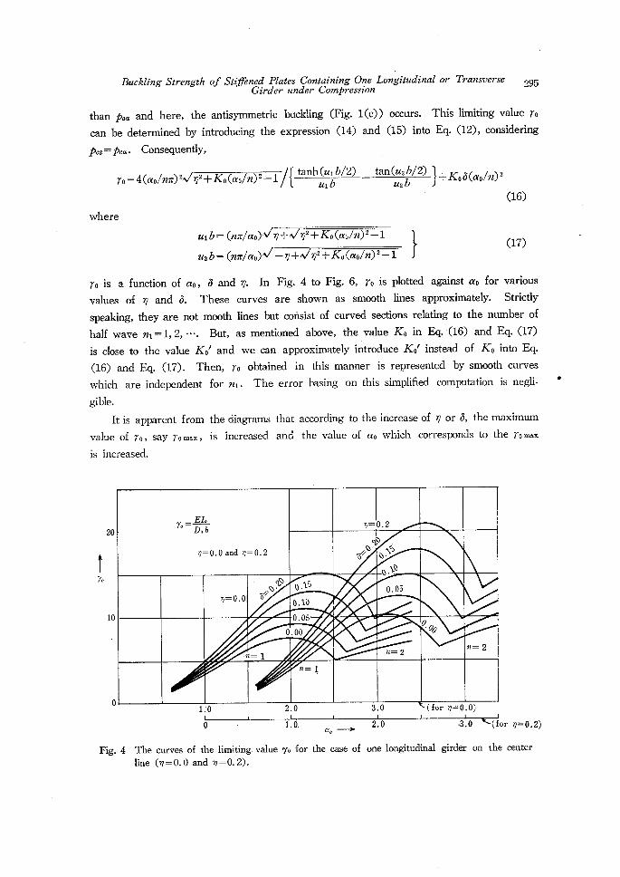
re is a function of ao, 6 and rp. In Fig. 4 to Fig. 6, ro is plotted against ao for various
values of ry and 6. These curves are shown as smooth lines approximately. Strictly
speaking, they are not mcoth lines but corisist of curved sections relating to the number of
half wave ni==1,2,・・・. But, as mentioned above, the value Ko in Eq. (16) and Eq. (17)
is close to the value Kot and we can approximately introduce Kot instead of Ko into Eq.
(16) and Eq. (17). Then, ro obtained in this manner is represented by smooth curves
which are independent for ni. The error hasing on this simplified computation is negli-
gible.
It is apparent from the diagrams that according to the increase of rp or 6, the maximum
value of ro, say romax, is increased and the value of cro which corresponds to the romax
is increased.
.
t%
20
10
o
EIe7e= rp]=O.2
Dxb
n=O.Oandn==O.2
sc"
S//"' ".Nts
".N"
n=o.o
pt5!/"'
o.15
O.10
O.05,
Q.Os
o.oo0・00
・n=1 n=2n=:2
n= l
1:o2.03.0(foro=O.O)Fig.4 The line
o・
curves of the limiting,
(n -= O.O and'n=O. 2).
value
1
7o
.o.
for
ae -the case of
2.0
one longitud
・3.
inal girder
O (for n=O.2)
on the center
.
296
tn
40
30
20
10
o
o
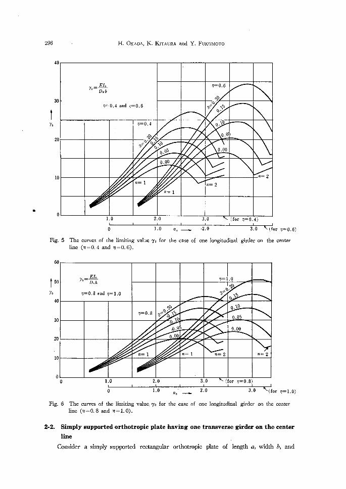
Fig. 5 The curves of
line (n=O.4
60
I5o
7o
40
30
20
IQ
o
o
Fig. 6 The curves of
line (op=O. 8 and
2'2r
line
Consider a simply
H. OKADA,・ K. KiTAuRA and Y. FuKuMoTo
7.=EIoDxb
n=O.4andn=O.6
o=O.6
""-
S/1NS".
V=O.4
"Nss
".N"
o.05
"・ "'N"fo1/".
".o5'o.ooo.oo
n=2n=1
n=1n=2
1.02.03.0(forn=O.4) L
the limiting value 7o
and op=O. 6).
o
for
cro -the case of
・2.0
one longitudinal
3.0
girder on
(for v=O.6)
the center
7o=EIe v=1.0Dxb
v==O.8ando=1.0 6!-
".x"
"i6
".l"
o=O.8
"s!!"i".N6
O.05,"."L",,b:O
5 o.oo
o.oo
n=1 n=1 n=2 n=2
o1.02.03.0(forrp±o.s) "tO .. 2.0 3・O ,(forn=1.o) ' the limiting value, 7o for the case of one longitudinal girder on the center
ny=1. 0).
Simply supported orthotropic plate having one transverse girder on the center
supported rectangular orthotropic plate of length a, width b, and
Buckling Strength of Stij7lened Plates Containing 04e Longitudinal or 7hansverse 2g7 irder under Compresston G
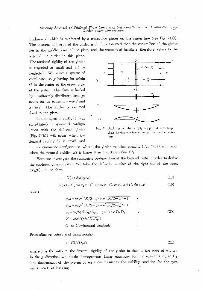
thickness t, which is reinforced by a transverse girder on the center line (see Fig. 7(a)).
The moment of inertia of the girder is L It is assumed that the center line of the girder
lies in the middle plane of the plate, and the moment of inertia L therefore, refers to the
axis of'the girder in this plane.
The torsional rigidity of the girder O -xis regarded as small and will be
neglected. We selectasystem of p .pcoordinates x, y having its origin (.)
O in the center of the upper edge
of the plate. The plate is loaded
・--:by a uniformly distributed load pt -acting on the edges x=-a/2 and
The is assumed (b)
£
girder(I)tta
22
i
),
x=a/2. girderfixed to the plate.
. In the region of aoS.V-2", (as (c) dtfr: :=:::><i ;stated later) the symmetric configu-
Fig. 7 Buckling of the simply supported orthotropicration with the defiected girder plate having one transverse girder on the center(Fig.7(b)) will occur when the line.flexural rigidity EI is srnall, and
the antisymmetric configuration where the girder remains straight (Fig. 7(c)) will occur
when the flexural rigidity EI is larger than a certain va!ue EIo.
Here, we investigate the symmetric configuration of the buckled plate in order to derive
the conditlon of instability. We take the defiection surface of the right half of the plate,
(x).O), in the form
wi -: X(x) sin(ay/b) (18) X(x) == Ci cos drnix+C2 sin itix+C3 cos tz2 x+C4 sin tz2x (19)
where
it,a-na,V(K/2-rp)+V('i-72-i)-2-1 1
u-2 a == zaoV (K/2- rp) - V (K7'2 - rp) 2 - 1
ao -= (a/b)VDw/D., rp == H/VD.Dy (20) K- ptb2/ (z2VDx Dw )
Ci to C4=:=integral constants.
Proceeding as before and using notation
r-Ell(Dwa) (21)where r is the ratio of the flexural rigidity of the girder to that of the plate of width a
in the bl direetion, we obtain hornogeneous linear equations for the constanbs Ci to C4.
The determinant of the system of equations furnishes the stability condit!on for the sym-
metric mode of buckling; -
N
298 H. OKADA, K. KiTAuRA and Y. FuKuMoTo
2(u-i2a2-tz22a2) -r(ncr,)`{ ta"(/',2."/2) - ta"(fiU',i."/2) }-o (22)
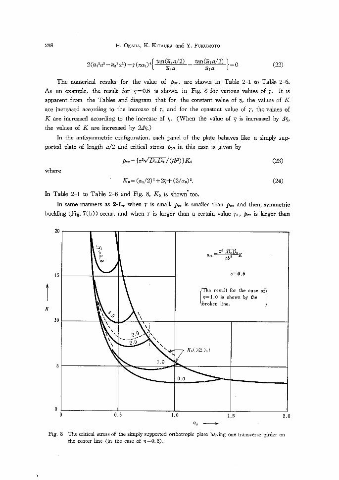
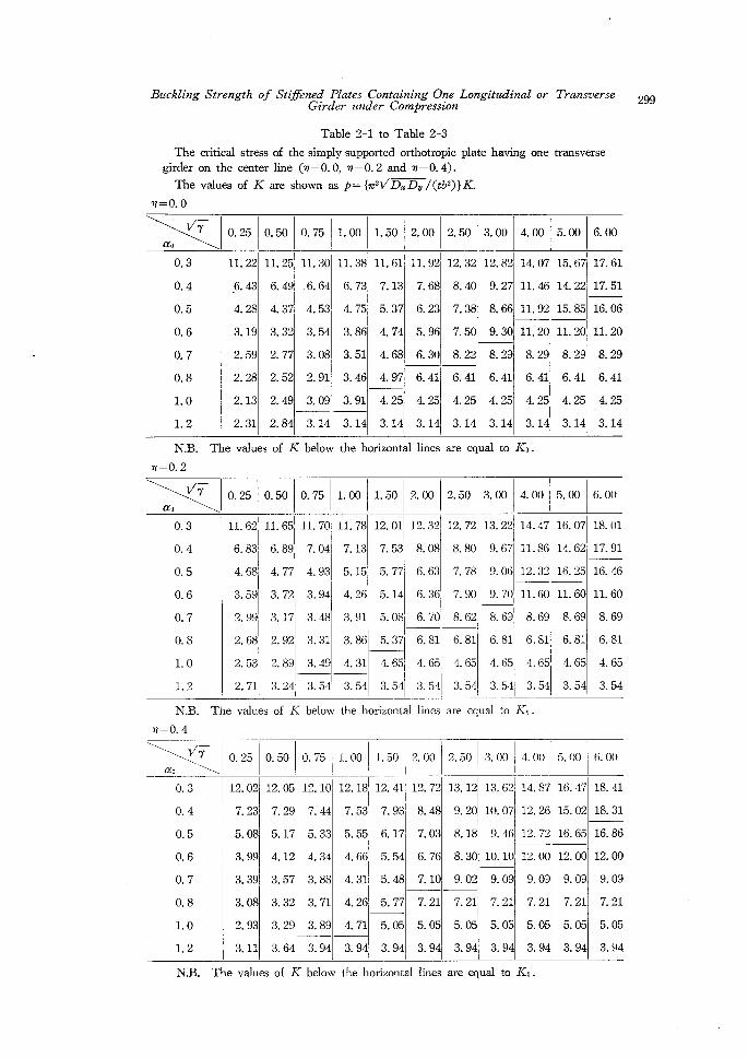
The numerical results for the value of pes, are shown in Tahle 2-1 to Tabie 2-6.
As an exampte, the result for rp=O.6 is shown in Fig. 8 for various values of r. It is
apparent frpm the Tables and diagram that for the constant value of ty, the values of K
are increased according to the increase of r, and for the constant value of r, the values of
K are increased according to the increase of rp. (When the value of rp is increased by Arp,
the values of K are increased by 2an.)
In the antisymmetric configuration, each panel of the plate behaves like a simply sup-
ported plate of length a/2 and critical stress pca in this case is given by
pca "{z2Jza Dv /(tb2)}Ko (23)where
' Ke=(ao/2)2+2rp+(2/cro)2. (24) .In Table 2-1 to Table 2-6 and Fig. 8, Ko is shown too.
In same manners as 2-1., when r is small, pcs is smaller than pca and then, symmetric
buckling (fig. 7(b)) occur, and when r is larger than a certain value re, pcs is larger than
20
TK
15
10
5
o
Fig.
t!x
"9o
NNeoN
NN
rfM;byKPcs:tb2
rp=O.6
Theresultforthecaseofn=1.0isshownbythebrokenline.
xNNVNNN
,v2."-AN.-.-t2.0
NNxlxN1.0
Ko("l)-)7o)
o.o
o
8
O.5 1.0 1.5 2.0 aoS 'The critical stress of the simply supported orthotropic plate having one transverse girder on
the center line (in the case of "=O.6).
'
.
Buckling Strength of St2Iffened .F7ates Containing One Longitudinal Girder under Compression
Table 2-1 to Table 2-3
The critical stress of the simply supported orthotropic plate having
girder on the center line (ny=O. O, ny=O.2 and ny=O. 4).
The values of K are shown as p== {T2Vb.Dv /(tb2)}K:
n=o. o
or
one
71ransverse
transverse
ao
V7-
O. 3
O. 4
O. 5
O. 6
O. 7
O. 8
1. 0
1. 2
O. 25
11. 22
6. 43'
4. 28
3. 19
2. 59
2. 28
2. 13
2. 31
O. 50
11. 25
6. 49
4. 37
3. 32
2. 77
2. 52
2. 49
2. 84
O. 75 1. 00
11. 30・
,6. 64
4. 53
3. 54
3. 08
2. 91
3. 09
3. 14
11. 38
6. 73
4. 75
3. 86
3. 51
3. 46
3. 91
3. 14
1. 50
11. 61
7. 13
5. 37
4. 74
4. 68
4. 97
4. 25
3. 14
2. 00
11. 92
7. 68
6. 23
5. 96
6. 30
6. 41
4. 25
3. 14
2. 50
12. 32
8. 40
7. 38
7. 50
8. 22
6. 41
4. 25
3. 14
3. 00
12. 82
9. 27
8. 66
9. 30
8. 29
6. 41
4. 25
3. 14
4. 00
14. 07
11. 46
ll. 92
11. 20
8. 29
6. 41
4. 25
3. 14
5. 00 6. 00
11Ii
15. 67
14. 22
15. 85
ll. 20
8. 29
6. 41
4. 25
3. 14
1
/
4
17. 61
17. 51
16. 06
11. 20
8. 29
6. 41
4. 25
3. 14
N.B.
T= O. 2
The values of K below the horizontal lines are equal to Ko.
ao
V7-
O.3
O. 4
O. 5
O. 6
O. 7
O. 8
1. 0
1.2
O. 25 O. 50 O. 75
11. 62
6. 83
4. 68
3. 59
2. 99
2. 68
2. 53
2. 71
1
1
Li
111. 65 L
6. 89 l
4. 77'
3. 72
1 3. 17i
2. 92,
2. 89
3. 24 1
11. 70
7. 04
4. 93
3. 94
3. 48
3. 31
3. 49
3. 54
1. 00
.l
lg1
L
I
11. 78
7. 13
5. 15
4. 26
3. 91
3. 86
4. 31
3. 54
1. 50 2. 00 2. 50 3. 00 4. 00
12. 01
7. 53
5. 77i
5. 14
5. 08・
5. 37'
4. 65
3. 54
,12. 321
8. 08
6. 63
6. 36
6. 70
6. 81
4. 65
3. 54
12. 72t
8. 80
7. 78
7. 90
s. 62I
6. 81
4. 65
3. 54
L13. 22i I l 9. 67
9. 06
9. 70・ s. 6gl
6. 81'
4. 65i
L 3. 54i
5. 00
14. 47
11. 86i l' 112. 32'
11. 60
8. 69
6.81
4.65・
3. 54
16. 07
14. 62
16. 25
11. 60
8. 69
6. 81
4. 65
3. 54
6. 00
//
:
18. 01
17. 91
16. 46
11. 60
8. 69
6. 81
4. 65
3. 54
N.B.
ny==O.4
The values of K below the horizontal lines are equal to Ko.
ao
vor-
O. 3
O. 4
O. 5
O. 6
O. 7
O. 8
1.0
L2
O. 25
12. 02
7. 23
5. 08
3. 99
3. 39
3. 08
2. 93
3. 11
O. 50 O. 75
i
1i 1. 00i1
s
1. 50
L12. 05i
7. 29
5. 17i
4. 12
3. 57
3. 32
3. 29
3. 64, f
12. 10
7. 44
5. 33
4. 34
3. 88
3. 71
3. 89
3. 94
s 12. Isl
7. 53
5. 55
4 66
4. 31
4. 26
4. 71
3. 94
12. 41
7. 93
6. 17
5. 54
5. 48
5. 77
5. 05
3. 94
2. 00 2. 50 i
13. 00 I 4. 00
1 1
5. 00
i
6. 00
12. 72
8. 48
7. 03
6. 76
7. 10・
7. 21
5. 05
3. 94
the horizontal lines
l13. 12
9. 20
8. 18
8. 30
9. 02
7. 21
5. 05
3. 94
I13. 621
10. 07
9. 46,
10. 10
9. 09
7. 21
5. 05
3. 94
14. 87
12. 26
12. 72
12. 00
9. 09
7. 21
5. 05
3. 94
I
i
16. 47
15. 02
16. 65
12. 00
9. 09
7. 21
5. 05
3. 94
18. 41
18. 31
16. 86
12. 00
9. 09
7. 21
5. 05
3. 94
N.B. The values of K below are equal to Ke.
299
300
The girder
The
ny-O.6
critical
on the
values
H. OKADA, K. KITAuRA and Y. FuKuMoTo
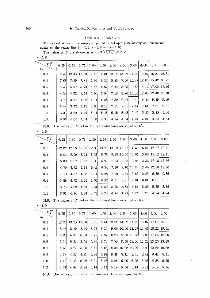
Table 2-4 to Table 2-6
strees of the simply supported orthotropic plate having
center line (ny==O. 6, ny==O.8 and op=1.0).
of K are shown as p={rr21/D.Dv/(tL2)}K
one transverse
ae
V7-
O. 3
O. 4
O. 5
O. 6
O.7
O. 8
LO1. 2
O. 25
12. 42
7. 63
5. 48
4. 39
3. 79
3. 48
3. 33
3. 51
O. 50
12. 45
7. 69
5. 57
4. 52
3. 97
3. 72
3. 69
4. 04
O. 75
12. 50
7. 84
5. 73
4. 74
4. 28
4. 11
4. 29
4. 34
1. 00
12. 58
7. 93
5. 95
5. Q6
4. 71
4. 66
5. 11
4. 34
1. 50
12. 81
8. 33
6. 57
5. 94
5. 88
6. 17
5. 45
4. 34
2. 00 2. 5013. 00
13. 12
8. 88
7. 43
7. 16
7. 50
1
/
1
113. 52
9. 60・
8. 58
8. 70
9. 42
7. 61
5. 45
4. 34
7. 61
5. 45
4. 34
14. 02
10. 47
9. 86
10. 50
9. 49
7. 61
5. 45
4. 34
4. 00
15. 27
12. 66
13. 12
12. 40
9. 49
7. 61
5. 45
4. 34
5. 00
16. 87
15. 42
17. 05
12. 40
9. 49
7. 61
5. 45
4. 34
6. 00
1
18. 81
18. 71
17. 26
12. 40
9. 49
7. 61
5. 45
4. 34
N.Bop == O. 8
. The values of K below the horizontal lines are equal to Ke.
ao
V7-
O.3
O. 4
O. 5
O. 6
O.7
O. 8
LO1. 2
O. 25 O. 50
112. 82i
8, 03
5. 88・
4. 79
4. 19
3. 88i
3. 73
3. 91
12. 85
8. 09
5. 97
4. 92
4. 37
4. 12
4. 09
4. 44
O. 75 1. 00 1. 50
12. 90
8. 24
6. 13
5. 14
4. 68
4. 51
4. 69
4. 74
I! 12. 98,
8. 33
6. 35j
5. 46・
5. 11
5. 06
5. 51
4. 74 1
13. 21
8. 73
6. 97
6. 34
6. 28
6. 57
5. 85
4. 74
2. oo
13. 52
9. 28
7. 83
7. 56
7. 90
8. 01
5. 85
4. 74
2. 50
13. 92
10. 00
8. 98
9. 10
9. 82
3. 00
14. 42
10. 87
10. 26
10. 90
9. 89
8. 01
5. 85
4. 74
4. oo
j'
l
15. 67
13. 06
13. 52
8. 01
5. 85
4. 74
12. 80
9. 89
8. 01
5. 85
4. 74
5. 00
17. 27
15. 82
17. 45
12. 80
9. 89
8. 01
5. 85
4. 74
6. 00
19. 21
19. 11
17. 66
12. 80
9. 89
8. 01
5. 85
4. 74
N.B.
op==LO
The values of K below the horizontal lines are equal to Ko.
ao
V7-
O. 3
O.4
O. 5
O. 6
O.7
O.8
LO
L2
O. 25
13. 22
8. 43
6. 28
5. 19
4. 59
4. 28
4. 13
4. 31
O. 50
13. 25
8. 49
6. 37
5. 32
4. 77
4. 52
4. 49
4. 84
O. 75
13. 30
8. 64
6. 53
5. 54
5. 08
4. 91
5. 09
5. 14
1. 00
13. 38
8. 73
6. 75
5. 86
5. 51
5. 46
5. 91
5. 14
1. 50
13. 61
9. 13
7. 37
6. 74
6. 68
6. 97
6. 25
5. 14
2. 00
13. 92
9. 68
8. 23
7. 96
8. 30
1
8. 41
6. 25
5. 14
2. 50 3. 00
14. 32
10. 40
9. 38
9. 50
10. 22'
8. 41
6. 25
5. 14
14. 82
11. 27
10. 66
11. 30
10. 29
8. 41
6. 25
5. 14
4. 00
16. 07
13. 46
13. 92
13. 20
10. 29
8. 41
6. 25
5. 14
5. 00
17. 67
16. 22
17. 85
13. 20
10. 29
8. 41
6. 25
5. 14
6. 00
19. 61
19. 51
18. 06
13. 20
10. 29
8. 41
6. 25
5. 14
NB. The values of K below the horizontal lines are equal to Ko.
L
/t
.
Buckling Strength of Stptned PZates Containing 04e Longitudinal or 7}'ansverse 3ol irder under Compresszon G
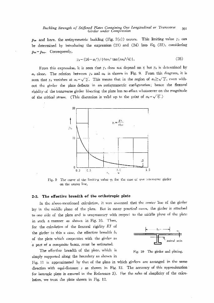
pcot and here, the antisymmetric buckling (Fig. 7(c)) occurs. This limiting value ro can
be determined by introducing the expression (23) and (24) into Eq. (22)s considering
Pcst==pca. Consequently,
ro- (16-cro`)/{4Tcro2 tan (Tao2/4)}. (25)
From this expression, it is seen that ro does not depend on n but ro is determined by
cro alone. The relation between ro and cro is shown in Fig. 9. From thls diagram, it is
seen that ro vanishes at cro=J'2-. This means that in the region of croi.llJ-2-, even with-
out the girder the plate deflects in an antisymmetric configuration; hence the flexural
rigidity of the transverse girder bisecting the plate has no effect whatsoever on the magnitude
of the critical stress. (This discussion is val!d up to the po!nt of cro-V'6-.)
'
20
i
Nt:'O
le
o O.3 O.5 ., 2sO 1'5
Fig. 9 The curve of the limiting value 7o for the case of one transverse giifder
ori the center line,
2-3. The effective breadth of the orthotropic plate
In the above-mentloned calculation, it was assumed that the center line of the girder
lay in the middle plane of the plate. But ln many practical cases, the girder is attached
to one side of the plate and is unsymmetry with respect to the middle plane of the plate
in such arnanner as shown in Fig. 10. Then,
for the calculation of the flexural rigidity EI of
the girder in this a case, the effective breadth be
of the plate which cooperates with the girder as
a part of a composite beam, must be estimated.
The effective breadth of the plate, whiCh iS Fig. Io The girder and plating.
simply supported along the boundary as shown in
Fig. 11 is approximated by that of the plate in which girders are arranged in the same
direction with equi-distance s as shown in Fig. 12. The accuracy of this approximation
for isotropic plate is assured in the Reference 3). For the sake of simplicity of the calcu-
lation, we treat the plate shown in Fig. 12.
EIo-n
7o=
'
DJta
L"2
・
-
eb,----bl..
Knutralaxis
302
o
v=eonst. .Ex=O
H. OKADA, K. KiTAuRA and Y. FuKuMoTo
.v=const.,ex==teSMWx
-----------q----
"x----'-""girder
v=const.,ex=O
--
"
x o
-.v=eonst.e:=eeslncax
-------------- ----K-Ei;d;.---'--- ----
1
Jv==const.ex=sosmcax
------"---- ----"'-K-gi;i・r----t;・ ----
N'xva
.v=const.ex=:eosmtux
.--"-.------s-.----------------- ----p-
x
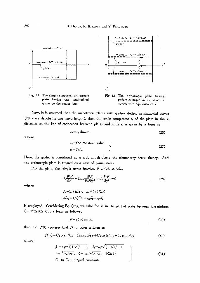
Fig. 11 The simplysupported orthotropic Fig. 12 The orthotropic plate having plate having one longitudinal girders arranged in the same di- girder on the center line. rection with equi-distarice s.
Now, it is assumed that the orthotropic plates with girders deflect in sinusoidal waves
(by 2 we denote its one wave length), then the strain c(rmponent ex of the plate in the x
direction on the line of connection between plates and girders, is given by a form as
ex=so sm tox (26)where
go==;:;zconstant value l (27)
'Here, the girder is considered as a web which obeys the elementary bearn theory. And
the orthotropic plate is treated as a case of plane stress.
For the plate, the Airy's stress function F ・which satisfies
04F 04F 04F Jle ox4 +2ellev ox2dy2 +Jb dy4 =O . (28)
where
JZs=1/(Evt), t7i"=1/(Erat)
2Jlev = 1/ (Gt) - vx tlb - vv Jle
is ernPloyed. Considering Eq. (26), we take for F in the part of plate between the girders,
(-s/2$pt$s/2), a form as fbllows;
F=-f(y)sinwx (29)then, Eq. (28) requires that .lt<y) takes a form as
.f< or) -= Ci coshPiy+C2 sinhPiy+C3 cosh P2 bl+C4 sinh P2y (30)
where
P,-tuptIC+VC2-1 , P,-tul]V4-V42-1
p-VJle/de, C-.ILv/VGde, (411) (31) Ci to C4== integral constants.
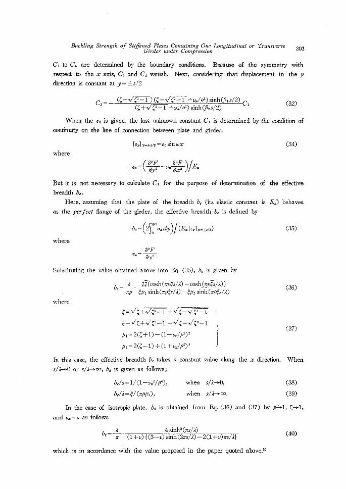
BucklingStrengthofStofentsl..dP.Z.ate.s.dCeo.ntcaStt.gesOt,n..e.Lo"gitudinalor7Vansuerse 3o3
Ci to C4 are determined by the boundary conditions. Because of the symmetry with
respect to the x axis, C2 and C4 vanish. Next, considering that displacement in'the y
direction is constant at y= ±s/2
(C+V42-1 ) (C-Avi42-1 +v./p2) sinh(Pis/2) C,- C, (32) (4+VC2-1 +v./p2) sinh(P2 s/2)
When the eo is given, the last unknown constant Ci is determined by the condition of
continuity on the line of connection between plate and girder.
[ex] w=±s12=eo sin (tix (34)where
.. ,. -=( oig -.. g2.F, )/,Ei,
But it is not necessary to culculate Ci for the purpese of determination of the effective
breadth be.
Here, assuming that the plate of the breadth be (its elastic constant is Ee) behaves
as the peiVfect flange of the girder, the effective breadth be is defined by
be == (2SS,!2ox dy)/ (Ex [ex] v-±sf2) (35)
62F C7hi = Oy2
Substituting the value obtained above into Eq. (35), be is given by
2 ge {cosh (np6s/2) - eosh (zpgs/2) } be= np' g-pti sinh (np.-'s/2) -ept2 sinh (zpJts/2) (36)
where
6--VC+VC2-1+VC-Vts"2-1 )
g-=Vc+Jc2-1-Vc-VC2-1 S c37) :l-:i[illi;[l;lil;iii j
In this case, the effective breadth be takes a constant value along the x direction. When
s/2.0 or s/2.oo, be is given as follows;
b,/s-1/(1-v.2/p`), when s/2-->O, (38)
be/2-e/(npai), when s/R->oo. (39)
In the case of isotropic plate, be is obtained from Eq. (36) and (37) by p-->1, C.1,
and vts==v as follows
be "= i' a+.) {(3 ri .)4,iS.":?;(.Z,;/2R))-2a+.) .,/2} (4e)
which is in accordance with the value proposed in the paper quoted above.3)
304 H. OKADA, K. I<iTAuRA and Y. FuKuMoTo
1.2
be
O.10
O.02
O O.2・ O.4 O.6 O.8 1.0 .. s/A-
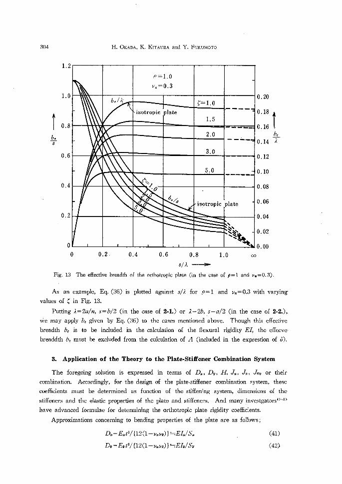
Fig. 13 The effective breadth of the orthotropic plate (in the case of p==1 and vx=O.3).
As an example, Eq. (36) is plotted against s/2 for p-1 and v.=O.3 with varying
values of 4 in Fig. 13. ' Putting 2==2a/n, s=b/2 (in the case of 2-1.) or 2-2b,,s-a/2 (in the case of 2-2.).
vte may apply be given by Eq. (36) to the cases mentioned above. Though this effective
breadth be is to be included in the calculation of the flexural rigidity EL the effecve
breaddth be must be excluded from the culculation of A (included in the exprestion of 6)..
3. Application of the Theory to the Plate-Stiffener Combination System
The foregoing solution is expressed in terms of D,, Dv, H; Jts, eTi, ellvv or their'
combination. Accordingly, for the design of the plate-stiffener combination system, these
coethcients must be determined as function of the stiffening system, dimensions of the-
stiffeners and the elastic properties of the plate and stiffeners. And many investgators`)"'8>
have advanced formulae for determining the orthotropic plate rigidity coeMcients.
Approximations concerning to bending propertles of the plate are as follows;
in=Ext3/{12(1-pmvv)}!=iElle/Sx (41)
Dv == Ey t3/ {12(1 ff vmvv)}'=iEh/Sv (42>
p=1.ev.==O.3
'
be/A'g=1.o
isotropicplate1.5
-------1-
2.0・"-h---h--,
--"-3.0
5.0d------
sStxx
!・0...ao
6e/s.isptropic
plate
NtN."
NkNN.q
Buckling Strength of 'Stij7lentsg..dP,l.atzs.dC ?.ntcaSn.ip.f.,O,,n..e.Longitudinal or Zl'blanswerse 3os
where
E=elastic constant of the material.
h, (h) =moment of inertia of the stiffener with effectve plating*
in the x, (bl) directlon.
Sln, -(Sv.) =spacing of the stiffener extending in the x, (ov) di・rection.
'The coethcient rp can be approximated by (due to Schade`))
rp =H/JDx Dv i=iVl}xu 4v/ (h h) (43)
where tt ' lbx, (4v)-moment of inertia of the effective p!ating* only, working
with stiffener, in the x, (N) direction.
To apply the theory in 2-1. and 2.2. to the plate-stiffener combination systm, we may use
these approximations. Further, t, which is used in the expression of p, 6 in 2-1. and 2-2.,
may be replaced by t.;- where t. is the equivarent thickness composed of the plate and
'stiffeners (diffused), in the directlon parallel to the co'mpressive load.
The remaining coefllcients .11,, .lb, blley which are used for determining the flexural
rigidity EI of the girder, are roughly associated with the membrane properties of the
plate5),7),8) and can be approximated by (see Reference 8)) '
v]L:=1/ (Ev t) Lil/ (Etv) (44)
eJi,=1/(Ext)'=il/(Etca) (45)where
t., (tv) -equivarent thickness of the plate and the stiffener (diffused)
in the x, (bl) direction.
ullev= {1/ (Gt) -vx h- vy e]le} /2!=i (1 +p)/(Etp) 'v/ (EtL) (46)
where
l,==2tthXit."k/.(IX,,+gWf)the piate aione. ] (47)
The coeMcients p(-Vo]le/tJb ) and C(-J]cv/VJ],h ) are approximately determined by using
Eq. (44) to (46). And v. is approximately given by
vm!=: (tx+tv) v/ (2tw) (48)
With these coethcients, the effective breadth be can be determined from Eq. (36). (Here,
the thickness of effective plating is the equivarent thickness in the direction parallel to the
girder (Fig. 12), and the elastic constant is E.) Then, the ratio r is determined and
critical stress can be calculated.
* In this
plates.case, we may use Eq. (40), (or Fig. 13), which gives the effective breadth be for lsotroplc
306 H. OKADA, K. KiTAuRA and Y. FuKuMoTo
4. Conclusion
In this study, we considerod the elastic buckling strength of a longitudinally compressed
rectangular plate which is reinforced by orthogonally intersecting stiffeners and one longi-
tudinal girder or transverse girder on the center line. The plate reinforced by orthQgonally
intersecting stiffeners is idealized by an equivarent orthotropic plate. And by means of the
theory of the orthotropic plate, we obtained the critical stress for the symmetric buckliing
in the case of r<ro and determined the limiting value ro. The effective breadth be of the
orthotropic plate which cooperated with the girder and was necessary in the calculation of
the flexural rigidity of the girder was also presented, ,
References
1) F. Bleich, Buckling Strength of Metal Structures, McGraw-Hill, New Yotk (1952).
2) S. P. Timoshenko and J. M. Gere, Theory of Elastic Stability, 2nd Ed., McGraw-Hill, New York
(1961).
3) K. Okuda and T. Arima, Trans. J.S.N.A., 58, 59 (1936).
4) H, A. Schade, Trans. S.N.A.M.E., 49, 154 (1941). 5) H. K611er, Jahrb. d. Deutschen Versuchsanstalt f. Luftfahrt (1939).
6) N. J. Hufungton and BIacksburg, J. App. Mech., 23, 15 (1956).
7) H. G. Schultz, Jahrb. d. Schiffbautechnischen Gesellschaft, 56, 182 (1962).
8) A. Mansour, I.S.P., 18, 202 (1971).
'


![Nonlinear Large Deflection Analysis of Stiffened Plates · Grondin et al. [11] made a parametric study on the buckling behaviour of stiffened plates using the FEM-based commercial](https://img.pdfslide.us/doc/110x75/5b895e247f8b9a5b688d7b93/nonlinear-large-deflection-analysis-of-stiffened-plates-grondin-et-al-11.jpg)
![Analysis of Rectangular Stiffened Plates Based on FSDT ...journals.iau.ir/article_533187_941593adfb53fefff6a1f1c...stiffened plates include grillage model [1] and orthotropic model](https://img.pdfslide.us/doc/110x75/611987e0da7612591d4b1661/analysis-of-rectangular-stiffened-plates-based-on-fsdt-stiffened-plates.jpg)