Embed Size (px)
Citation preview
L. (. .
NASA TECHNICAL NOTE --- N A S A T_N D - 5 5 6 1 --
e. /
* WAN CmOPY: R E m TO AFWL (WLOL)
KIRTfJWD A,FB, N Mat
BUCKLING OF STIFFENED CYLINDERS I N AXIAL COMPRESSION AND BENDING- A REVIEW OF TEST DATA
9
by Jmnes. P. Peterson
LaizgZey Research Center LangZey Stdti092~ Hct112pto~~ Va.
N A T I O N A L A E R O N A U T I C S A N D SPACE A D M I N I S T R A T I O N WASHINGTON, D. C. DECEMBER 1 9 6 9
I
TECH LIBRARY KAFB, "l
19. Security Clossi f . (of t h i s report)
Unclassified
'
20. Security Clossi f . (of th is page) 21. No. o f Pages 22. Price"
Unclassified I 25 1 $3.00
,
2. Government Accession No. I 1. Report No.
NASA TN D-5561
4. T i t l e ond Subtit le
BUCKLING OF STIFFENED CYLINDERS I N A X I A L COMPRESSION AND
BEND I NG - A REVIEW OF TEST DATA
7. Author(s)
James P. Peterson
9. Performing Organization Name and Address
NASA Langley Research Center
Hampton, Va. 23365
2. Sponsoring Agency Name and Address
National Aeronaut ics and Space Administrat ion
Washington, D.C. 20546
5. Supplementary Notes
6. Abstract
3. Recipient 's Cotalog No.
5. Report Date
December 1969 6 . Performing Organization Code
8. Performing Organization Report No.
L-6767 I O . Work Un i t No.
722-DZ-10-05-23 11. Controct or Grant No.
13. Type o f Report and Per iod Covered
Tech n ica I Note
14. Sponsoring Agency Code
Test data o n stiffened cyl inders w h i c h failed by general instabi l i ty under u n i f o r m axial compression
and/or bending are reviewed, and t h e adequacy of contemporary methods for predict ing buckl ing a re
appraised by comparing test data w i th resu l t s obtained f r o m a contemporary buckl ing theory. Buck l i ng
fa i l u res of well-constructed cyl inders w i th 4 5 O waffle st i f fening were experienced at loads as low as
65 percent of t h e loads calculated for t he cyl inders, and other cyl inders of d i f ferent cons t ruc t i on failed at
loads approaching t h e 65-percent value. The latter cy l i nde rs i nc lude both isotropic and corrugated c y l i n -
de rs w i th r i n g stiffening, t h e on ly other types of cons t ruc t i on for w h i c h m u c h test data a re available.
Hence, test ing t o date has not revealed any type of stiffened cyl inder cons t ruc t i on tha t fa i ls by general
instabi l i ty but is immune to low fa i l i ng loads, and design methods w h i c h neglect t h e dispar i ty between
theo ry and test a re l ikely to be unconservative.
. 17. Key Words Suggested by A u t h o r k )
Stiffened cy l i nde rs
Axial compression a n d bending
Buckl ing
18. D is t r ibu t ion Statement
Unclassified - Unl imited
BUCKLING OF STIFFENED CYLINDERS IN AXIAL COMPRESSION
AND BENDING - A REVIEW OF TEST DATA
By James P. Peterson Langley Research Center
v
SUMMARY
Test data on stiffened cylinders which failed by general instability under uniform axial compression and/or bending are reviewed, and the adequacy of contemporary methods for predicting buckling a r e appraised by comparing test data with resul ts obtained from a contemporary buckling theory. cylinders with +45O waffle stiffening were experienced at loads as low as 65 percent of the loads calculated for the cylinders, and other cylinders of different construction failed at loads approaching the 65-percent value. The latter cylinders include both isotropic and corrugated cylinders with ring stiffening, the only other types of construction for which much tes t data are available. Hence, testing to date has not revealed any type of stiffened cylinder construction that fails by general instability but is immune to low failing loads, and design methods which neglect the disparity between theory and test are likely to be unconservative.
Buckling failures of well-constructed
INTRODUCTION
Several experimental investigations of buckling of stiffened cylinders in axial com- pression o r bending have recently appeared in the l i terature. These investigations contain information that is extremely valuable to designers who must rely
safe level. The usefulness of the data is compromised to some extent, however, by lack
fer in certain respects ; these differences and the influences of the differences are not readily apparent f rom the references. In the present study the data are reviewed and compared with a single buckling theory, and the differences between the calculations made herein and those of the various investigators are discussed.
(See refs. 1 to 9.)
. on such data to obtain correlation factors which cor rec t calculated buckling loads to some
of a common basis of comparison. The calculations from the various investigations dif-
The review provides an opportunity to assess the adequacy of available data for design purposes; hence, the data are studied and their validity appraised for use in devising a correlation factor. Much of the data had to be rejected as being deficient i n
some respect. The reasons for rejection and the adequacy of the remaining data are discussed.
SYMBOLS
The units for physical quantities i n this paper are given both in the U.S. Customary Factors relating the two systems are Units and in the International System of Uni t s (SI).
given i n reference 10; those factors used in the present paper a r e given in appendix A.
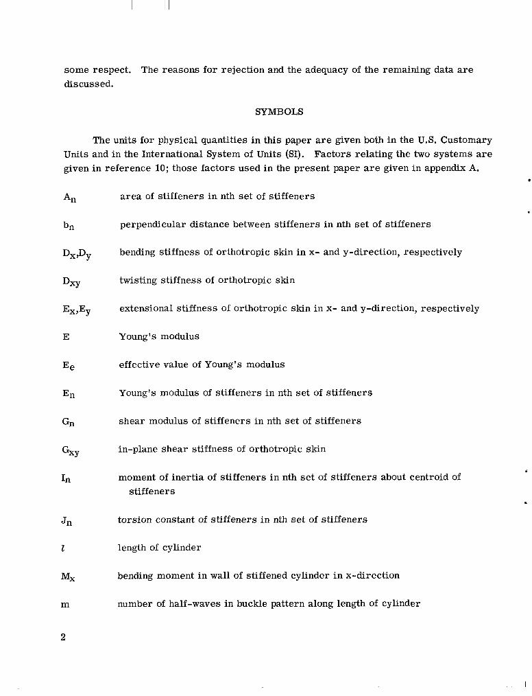
a rea of stiffeners i n nth set of stiffeners
perpendicular distance between stiffeners in nth se t of stiffeners
bending stiffness of orthotropic skin in x- and y-direction, respectively
twisting stiffness of orthotropic skin
extensional stiffness of orthotropic skin in x- and y-direction, respectively
Young's modulus
effective value of Young's modulus
Young's modulus of stiffeners in nth set of stiffeners
shear modulus of stiffeners in nth se t of stiffeners
in-plane shear stiffness of orthotropic skin
moment of inertia of stiffeners in nth se t of stiffeners about centroid of stiffeners
torsion constant of stiffeners in nth se t of stiffeners
length of cylinder
bending moment i n wall of stiffened cylinder i n x-direction
number of half-waves in buckle pattern along length of cylinder
NX
- N
- NO
=x,Ns,
n
r
V
W
- E
B
€cr
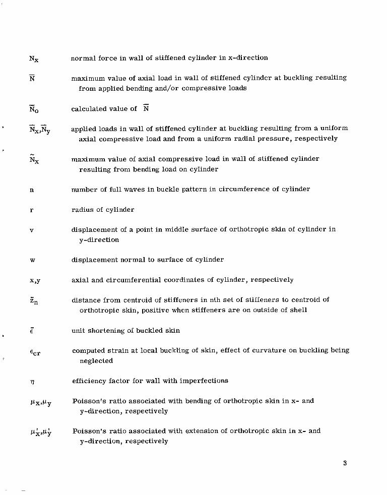
normal force in wall of stiffened cylinder i n x-direction
maximum value of axial load in wall of stiffened cylinder at buckling resulting from applied bending and/or compressive loads
calculated value of E
applied loads in wall of stiffened cylinder at buckling resulting from a uniform axial compressive load and from a uniform radial pressure, respectively
maximum value of axial compressive load in wall of stiffened cylinder resulting from bending load on cylinder
number of full waves in buckle pattern in circumference of cylinder
radius of cylinder
displacement of a point in middle surface of orthotropic skin of cylinder i n y-direction
displacement normal to surface of cylinder
axial and circumferential coordinates of cylinder, respectively
distance from centroid of stiffeners in nth se t of stiffeners to centroid of orthotropic skin, positive when stiffeners are on outside of shell
unit shortening of buckled skin
computed s t ra in at local buckling of skin, effect of curvature on buckling being neglected
efficiency factor for wall with imperfections
Poisson's ratio associated with bending of orthotropic skin i n x- and y-direction, respectively
Poisson's ra t io associated with extension of orthotropic skin i n x- and y-direction, respectively
3
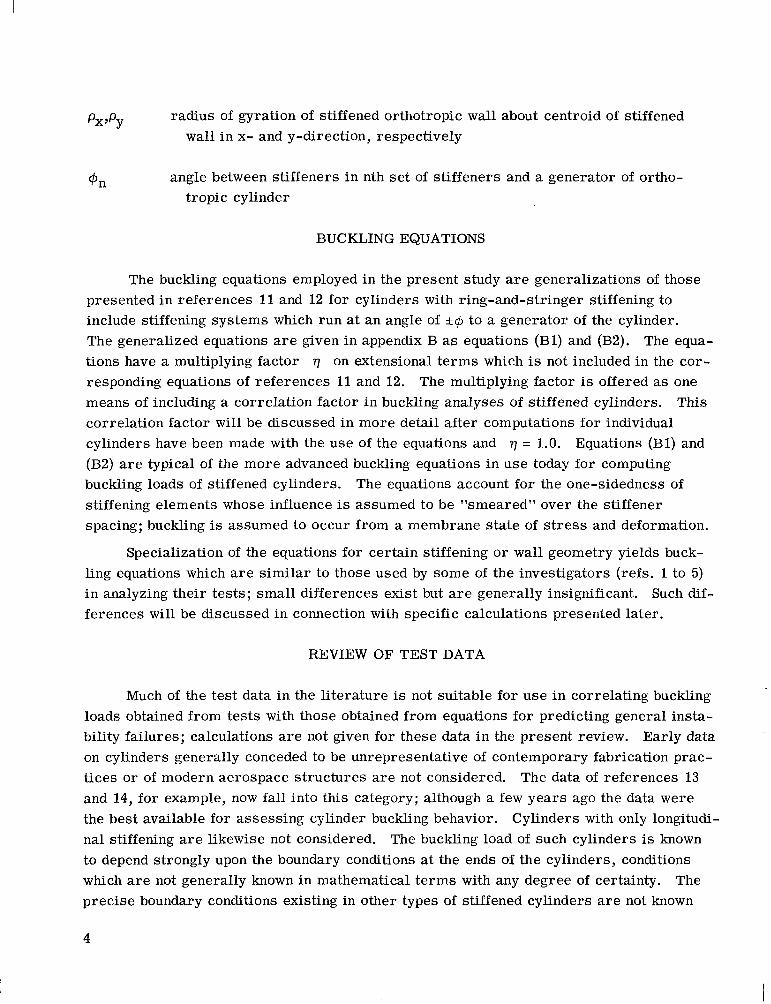
radius of gyration of stiffened orthotropic wall about centroid of stiffened PX'PY wall i n x- and y-direction, respectively
angle between stiffeners in nth set of stiffeners and a generator of ortho- @n tropic cylinder
BUCKLING EQUATIONS
The buckling equations employed in the present study are generalizations of those presented in references 11 and 12 for cylinders with ring-and-stringer stiffening to include stiffening systems which run at an angle of &$I to a generator of the cylinder. The generalized equations are given in appendix B as equations (Bl) and (B2). The equa- tions have a multiplying factor q on extensional t e rms which is not included in the cor- responding equations of references 11 and 12. means of including a correlation factor in buckling analyses of stiffened cylinders. This correlation factor wi l l be discussed in more detail after computations for individual cylinders have been made with the use of the equations and q = 1.0. Equations (Bl) and (B2) are typical of the more advanced buckling equations in use today for computing buckling loads of stiffened cylinders. stiffening elements whose influence is assumed to be "smeared" over the stiffener spacing; buckling is assumed to occur from a membrane state of stress and deformation.
Specialization of the equations for certain stiffening o r wall geometry yields buck- ling equations which are s imilar to those used by some of the investigators (refs. 1 to 5) i n analyzing their tes ts ; smal l differences exist but are generally insignificant. Such dif- ferences will be discussed in connection with specific calculations presented later.
The multiplying factor is offered as one
The equations account for the one-sidedness of
REVIEW OF TEST DATA
Much of the test data in the l i terature is not suitable for u se in correlating buckling loads obtained from tests with those obtained from equations for predicting general insta- bility failures; calculations are not given for these data in the present review. Early data on cylinders generally conceded to be unrepresentative of contemporary fabrication prac- t ices or of modern aerospace s t ructures are not considered. The data of references 13 and 14, for example, now fall into this category; although a few years ago the data were the best available for assessing cylinder buckling behavior. Cylinders with only longitudi- nal stiffening are likewise not considered. to depend strongly upon the boundary conditions at the ends of the cylinders, conditions which are not generally known in mathematical t e rms with any degree of certainty. precise boundary conditions existing in other types of stiffened cylinders are not known
The buckling load of such cylinders is known
The
4
either, but the sensitivity of buckling load to detail changes in end conditions is not as significant. Hence, tes t s of axially stiffened cylinders should be subjected to a different scrutiny than tests of other types of stiffened cylinders, and a study of their behavior could well constitute a separate investigation.
Some of the newer data are also deficient. These data are included in the present study to the extent that the deficiencies of the data a r e discussed, but buckling calcula- tions are not given. This discussion is given after buckling calculations a r e presented for the cylinders of primary interest in the present study.
The test data analyzed were obtained on cylinders of four basic types of construc- tion: cylinders with *45O stiffening, cylinders with ring stiffening, corrugated cylinders with ring stiffening, and cylinders with ring-and-stringer stiffening. The data on corru- gated ring-stiffened cylinders were obtained in three separate investigations; data on the other three types of construction a r e limited to single investigations.
Cylinders With *45O Stiffening
The tes ts of reference 1 were conducted on *45O integrally stiffened circular cyl- inders. mandrel inside the cylinders to control buckle depth and to preserve the cylinders for further testing. in-plane axial compression was a maximum at one generator of the tes t cylinder and zero at the diametrically opposed generator. Use of the mandrel was largely successful in preventing damage to the cylinders, and two o r three tes t s (the maximum number attempted) were conducted on each cylinder; the maximum compressive s t r e s s in suc- cessive tes ts was applied to a generator 1200 from that in the previous test.
Most of the tes t s were conducted on 96-inch-diameter (2.44-m) cylinders with a
Loading was a combination of bending and axial compression so that the
The cylinders were relatively lightly stiffened; the stiffening members constituted about 25 percent of the mass of the cylinders. s t resses ; the maximum axial compressive s t r e s s was generally less than 15 ksi (103 MN/m2) and the stiffener s t r e s s less than about 5 ksi (34 MN/m2).
Buckling occurred at relatively low
1 The resul ts of calculations to predict buckling loads a r e given in table I. The most
significant characterist ic is the scat ter of test resul ts f rom 65 to 105 percent of the cal- culated buckling load. the use of cylinder dimensions i n the neighborhood of the maximum s t ressed generator as input for buckling calculations. Such a scheme would be expected to reduce scat ter more than that obtained with the use of a single average set of dimensions for a given cylinder.
The scat ter exists in spite of attempts to minimize scat ter with
The calculated resul ts given in table I differ slightly from those given in reference 1 in presenting the data. stiffness of stiffeners and neglect of the variation of s t r e s s in the circumferential
The difference is presumably associated with neglect of twisting
5
I
direction i n the analysis of reference 1. Small differences may also exist from geome- tries used i n the two sets of calculations. (approximately 1/32-inch (0.8-mm)) fillet i n the re-entrant corner between stiffeners and skin; presumably, the calculations of reference 1 did not. In the present calculations, neglect of stiffener twisting stiffness would have decreased the calculated buckling loads of table I by about 3 percent; neglect of the variation in stress distribution would have decreased the calculated buckling load by about 2- percent.
The present calculations include a small
1 2
1
Ring-Stiffened Cylinders
The test specimens of reference 2 consisted of eighteen 14-inch-diameter (35.6-cm) ring-stiffened cylinders machined from steel tubes with a n initial wall thickness of 1/4 inch (6.4 mm). from approximately 600 to 750; stiffening ratio varied so that 10 to 30 percent of the mass of the cylinders was in the rectangular rings.
Ratios of radius to skin thickness of the finished cylinders varied
The cylinders were tested in axial compression. Several cylinders had small mar- gins against failure by local buckling of the skin between rings, and their failure may have been influenced by the local buckling. Hence, only those cylinders with a calculated mar- gin of at least 15 percent against failure in the local mode are considered herein for eval- uation of l inear theory in predicting general buckling. wall stress of less than 30 ksi (207 MN/m2); the yield stress of the wall material is reported to be about 70 ksi (483 MN/m2).
Buckling generally occurred a t a
Calculated buckling loads of these test cylinders are given in table II. Buckling loads as observed from tes t s vary from 67 to 97 percent of those calculated with the use of equation (Bl). Buckling was always calculated to occur in an axisymmetric mode; the number of axial half-waves m in the calculated buckle pattern is shown in the table. This number is not very different from the number of rings in the test cylinders. Although this situation suggests that the effect of ring discreteness (not accounted for in eq. (Bl)) might be expected to be important for the test cylinders, this question was investigated in reference 2, and only insignificant changes in calculated buckling load were found when ring discreteness was taken into account.
Ring-Stiffened Corrugated Cylinders
Ring-stiffened corrugated cylinders are the only type of construction on which more than one investigation was conducted and for which buckling calculations are given herein. These investigations are reported in references 3 to 5.
Test specimens of reference ~ - .. 3.- The tes t specimens of reference 3 consisted of ring-stiffened corrugated cylinders of 7075-T6 aluminum alloy which were tested in axial compression or combined axial compression and ber.ding. Test cylinders of three s izes ,
6
ranging from approximately 50 inches (1.27 m) in diameter to nearly 400 inches (10.16 m) in diameter, were used i n the study. cent of the mass of the cylinder for the largest specimen to up to 40 percent of the mass of the test cylinder for one of the smaller test cylinders. s t r e s ses between 35 ksi (241 MN/m2) and 45 ksi (310 MN/m2). Only those test cylin- de r s with I-section rings are considered here. Results for two cylinders with channel- section rings are also reported in reference 3, but published information is incomplete, and independent calculations could not be made.
The mass of stiffening rings ranged from 20 per-
The cylinders failed at
L The resul ts of calculations to predict buckling of the test cylinders are given i n table III. Buckling occurred at loads 88 to 103 percent of those calculated for the test cylinders. cipal difference is for cylinder 6 which was tested in combined bending and axial com- pression. Reference 3 reports a discrepancy between theory and test approximately 7 percent greater than that shown in table III. Buckling in reference 3 was calculated with the use of an improvised "bending factor" and a calculation for buckling in uniform axial compression. The buckling load given in table It1 was obtained by direct calculation for combined bending and compression. In addition, the calculations for table I11 were made with somewhat different stiffnesses to represent the corrugated skin than were used in reference 3. calculations - some of those stiffnesses were neglected in the calculations of reference 3, evidently without significant change in calculated results.
These values do not differ much from those given in reference 3. The prin-
The stiffnesses given in reference 4 were used in the present
Test specimens of reference 4.- The tes t specimens of reference 4 consist of five ring-stiffened corrugated cylinders of 7075-T6 aluminum alloy in which a single corruga- tion geometry and ring geometry were used in fabrication of the cylinders. The differ- ence between test cylinders lies in ring spacing which varied from cylinder to cylinder. Failure of the cylinder with the greatest ring spacing was by panel instability, that is, by buckling between rings. tested i n bending. ened cylinder for those cylinders which failed by general instability. led at stresses of l e s s than 35 ksi (241 MN/m2).
The cylinders were 78 inches (1.98 m) in diameter and were The rings contributed from 15 to 35' percent of the mass of the s t i f f -
All cylinders buck-
Results of calculations to predict buckling of the test cylinders are given in table IV. Buckling occurred at loads from 88 to 102 percent of those calculated for the tes t cylin- de r s with the use of equation (B2). These values are greater than those presented in ref- erence 4, which were based on an incorrect calculation for ring properties. The present calculations make use of the ring geometry shown in figure 2 of reference 4, the geometry of the rings used in construction of the test cylinders.
Test specimens of reference 5.- The test cylinders of reference 5 consist of two ring-stiffened corrugated cylinders of 7075-T6 aluminum alloy, one with rings on the
7
outside of the corrugated wall and one with rings on the inside. 21 percent of the mass of the cylinders. diameter and were tested in bending.
The rings contributed The cylinders were 78 inches (1.98 m) in
Results of calculations to predict buckling of the test cylinders are given in table V. These resul ts differ little from those given in reference 5 i n presenting the original data.
Cylinders With Ring-and-Stringer Stiffening
The test specimens of reference 6 were cylinders with ring-and-stringer stiffening
The 77-inch-diameter (1.96-m) cylinders, which were tested in bending, were which experienced local buckling of the skin long before general buckling of the shell occurred. ra ther heavily stiffened. Stiffening elements accounted for 40 to 50 percent of the mass of the stiffened cylinders; the s t r ingers contributed more than the rings.
The usefulness of the tests of reference 6 in appraising the adequacy of contempo- r a r y buckling theories for predicting general instability of stiffened cylinders is tempered by the degree to which some of the stiffnesses of buckled skin can be defined. Many of the stiffnesses a r e not known with sufficient accuracy to eliminate significant e r r o r s in predicted load from this source. r a r y interest , and therefore the tests are included in the present calculations, but the cal- culated resul ts a r e not used later when the correlation of test data with analysis is discussed.
However, this type of construction is one of contempo-
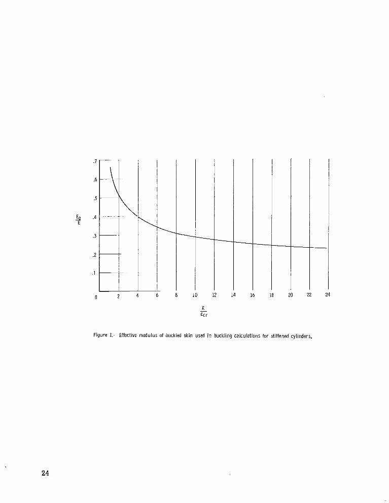
The buckled skin was treated in an approximate manner in the buckling calculations. It was assumed that buckled skin could be treated in the same manner as unbuckled skin if it were assigned an effective value for Young's modulus. The value assigned to mod- ulus is given in figure 1 and was ascertained by comparing buckling resul ts for the tests of reference 6 with those for the r e s t of the tes ts considered in the present investigation. Other considerations entailed in obtaining figure 1 are given in appendix C.
Results of calculations to predict general buckling of the test cylinders of refer- ence 6 are given in table VI. The first six cylinders failed by general instability; the remaining cylinder failed by panel instability. The rat ios of mmo for those cylinders which failed by general instability fall within the range of the rest of the data given in tables I to V.
The cylinders of reference 6 were recently analyzed in reference 15 with the use of stiffnesses for buckled skin reported in reference 16 for flat plates. between 0.87 and 1.11 were obtained in those calculations, but incorrect values for exper- imental buckling load E were used in the calculations. Errors in as large as 25 percent were entailed i n deriving
Ratios of m[fio
from the applied bending moment on the
8
cylinders at buckling from neglect of the influence of local skin buckling in changing stress distribution and cylinder bending stiffness.
Data Unsuitable for U s e in This Study
The data from two recent investigations were not used in the present study.
Test specimens of references 7 and 8.- The test specimens of references 7 and 8 consisted of small-diameter (7.6-inch (19.3-cm)) machined cylinders with ring stiffening, grid stiffening, o r longitudinal stiffening. loadings. compression would normally have been of interest in the present study. characterist ics of the test cylinders render them unsuitable for evaluating the validity of contemporary analyses in predicting cylinder buckling; hence, resul ts of the investigation are not studied in detail herein.
L The cylinders were subjected to various
The ring-stiffened and grid-stiffened cylinders subjected to bending o r axial However, two
c
The first characterist ic is the small s ize of the tes t cylinders and the associated tolerances on cylinder dimensions. surements could be made to reasonable accuracy (less than 5-percent e r ro r ) , dimensional variation from one par t of a cylinder to another is not discussed; because the specimens were small (r = 3.8 inches (9.7 cm)), rather significant variations in dimensions would be expected. Some idea of thickness variations can be gleaned from the data presented. For instance, table 4.1 of reference 7 indicates that a minimum skin thickness of 0.0060 inches (0.152 mm) was measured on one of the three grid-stiffened cylinders tested in axial compression. Presumably, the measurement was made on cylinder 6 1, the grid-stiffened cylinder with the thinnest skin. average skin thickness) of 0.0087 inches (0.221 mm) (table 4.4 of ref. 7). sumptions a r e correct , this thickness corresponds to a 30-percent variation from the reported o r average thickness. If the 0.0060-inch (0.152-mm) measurement were made on one of the other two grid-stiffened cylinders, an even larger variation would be indicated.
Although references 7 and 8 indicate individual mea-
This cylinder had a reported skin thickness (presumably If these pre-
The other undesirable characterist ic of the tes t cylinders is associated with stiff- ener geometry. stiffeners is about the same as the width of the stiffener. more like plates than stiffeners and such behavior should be taken into account in corre- lating tes ts with analysis. Unfortunately, analyses which properly t rea t such stiffeners a r e unavailable because they are not normally needed in the design of aerospace s t ruc- tures; and the use of available analyses reveals little regarding the adequacy of the anal- yses in predicting buckling of the stiffened cylinders reported in references 7 and 8.
The stiffening is such that the clear distance between rectangular-shaped Such stiffeners probably behave
~~~ Test specimens of reference 9.- The test specimens in the investigation of refer- ence 9 consist of integrally stiffened cylinders with longitudinal, grid, o r *45O stiffening.
9
The cylinders were 53 inches (1.35 m) in diameter and were tested in uniform ax ia l com- pression. The grid-stiffened and the &45O stiffened cylinders would normally have been of interest in the present study. However, stiffening on the cylinders was such that local buckling of the skin between stiffeners occurred pr ior to general buckling; and, i n addi- tion, the cylinders had relatively light stiffening so that local buckling of the skin was influenced by the low deflectional stiffness of the st iffeners normal to the surface of the shell. It is believed that failure was also influenced by the low deflectional stiffness of the stiffeners; that is, the stiffening elements were not heavy enough to provide nodes in the local buckle pattern in the post local-buckling loading regime, and cylinder failure was associated with crippling of stiffener elements from local buckling patterns cutting ac ross stiffeners. Such failures are not amenable to calculation with the use of equations such as equation ( B l ) even when used in conjunction with effective stiffnesses for buckled skin as were the cylinders of reference 6; therefore, resul ts of detailed calculations are not presented herein.
DISCUSSION O F RESULTS
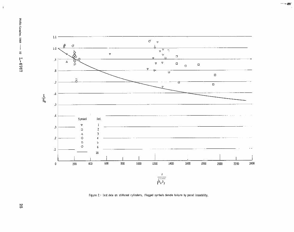
Results in tables I to VI are plotted against the parameter r/m in figure 2. This parameter has been suggested (ref. 17) as one which can be used to integrate tes t data on stiffened cylinders with the large mass of data on unstiffened cylinders and thereby render the unstiffened data useful in the design of stiffened cylinders. The search for such a parameter was instigated by the lack of data on stiffened cylinders. Also plotted in figure 2 is a curve taken from reference 18 which represents the lower limit of the bending data o r an average of the compression data of the unstiffened cylin- d e r s considered in the reference.
The data on stiffened cylinders do not appear to correlate well with the parameter r//m, Particularly conspicuous are the data of reference 5 on ring-stiffened corru- gated cylinders; these cylinders buckled at approximately 70 percent of the calculated buckling load even though r/m was small and in the range where considerably
higher test loads would be expected on the basis of the parameter ./il/ij&. References 2 and 15 suggest that stiffening rat io (ratio of stiffener area to skin
This parameter immediately comes to mind because the unstiffened cylinder is area) should be an important parameter i n the correlation between test data and calcula- tion. approached as stiffening ratio is decreased, and the disparity between calculation and tes t for unstiffened cylinders is generally greater than that indicated herein for stiffened cyl- inders. However, when the data of tables I to VI were plotted against sti€fening ratio, no trends were detected.
10
The lower limit of the data of figure 2 is suggested for design purposes for lack of a better correlation factor, that is, N/No = 0.65. sented in figure 2 experienced general instability failures near the 0.65 value except the cylinders with ring-and-stringer stiffening of reference 6, and the cylinders of refer- ence 6 cannot logically be used to establish correlation because their buckling loads were determined with the use of data from the other cylinders represented in figure 2, as explained previously. Hence none of the types of construction for which data are avail- able appear to be immune to the low failing loads. to considerable test scatter. Each type of construction experienced values of N/No which scat ter between a value near 0.65 to a value near unity.
- - Each basic type of construction repre-
Moreover, none appear to be immune & - -
I
The e€fects of geometric initial imperfections and built-in fabrication o r residual stresses probably account for much of the test scat ter exhibited in figure 2; of the two, imperfections are perhaps more important than residual s t resses . Most of the tests of reference 1 were conducted on nominally identical cylinders, and the tests of reference 2 include some cylinders whose nominal dimensions differ little from those of other cylin- de r s in the ser ies . It is difficult to associate the observed scat ter in tes t resul ts for these tes ts with anything but initial imperfections o r residual Stresses. More sophisti- cated calculations which include prebuckling deformations of geometrically perfect cylin- ders , o r which better describe actual end conditions but which neglect geometric imper- fections, would not be expected to reduce the scat ter substantially; any calculation which would lower one point would lower the others accordingly. A more sophisticated example calculation (with the use of ref. 19) w a s made for cylinder 5 of the ring-stiffened cylin- de r s of reference 2 to determine the magnitude of the influence of discrete rings and non- linear prebuckling deformations on buckling load. in buckling load of only 6 percent. Similarly, the calculations made in reference 19 would indicate that inclusion of these effects i n the buckling calculations for ring-stiffened cor- rugated cylinders would have little influence on the resul ts presented in figure 2. Hence, unmeasured geometric imperfections and residual stresses seem to be left as the most likely cause of the scat ter i n tes t data exhibited in figure 2.
The calculation indicated a reduction
Considerable attention has recently been given to determining the sensitivity of
The study of reference 21 includes ring-stiffened representative shell s t ructures to loss of stability from geometric initial imperfections. (See refs. 20 and 21, for example.) cylinders loaded in axial compression. sensitive to imperfections is in accordance with the resul ts shown in figure 2. studies have not been made for the other shell s t ructures represented in the figure.
Its conclusion that ring-stiffened cylinders are Similar
Until studies of the imperfection sensitivity of shells in buckling have progressed to the extent that correlation of measured imperfections with analytical predictions has been ascertained, other, more approximate methods of predicting cylinder buckling, presumably
11
methods which inherently account for the most severe imperfections o r residual stresses likely to occur in fabrication, will have to be employed. shells representative of those considered in figure 2 is one way of accomplishing this effect.
The use of Rmo = 0.65 for
Another method, which parallels that of reference 18 for unstiffened cylinders, is to use equations (Bl) and (B2) with a multiplying factor q of less than unity. This scheme implies that imperfections have a detrimental effect on extensional stiffnesses that resul ts in lower buckling loads. Note that all stiffnesses associated with extension of the cylin- der wall, including those associated with shearing in the plane of the cylinder wall, are multiplied by the factor q. Coupling t e rms are multiplied by fi, and bending t e rms are left unchanged. Use of equation (Bl) i n this form resul ts in computed buckling loads for
many s t ructures which are proportional to fi independent of q as shell length is decreased and flat-plate behavior is approached, a trend that correlates well with observed behavior of shell structures.
and which converge to buckling loads
The use of equations (Bl) and (B2) with 17 < 1.0 fo r calculating general instability failures is equivalent to the use of the correlation factor N m o = 0.65 for correcting theoretical calculations to the lower limit of test data. The corresponding value of q is (0.65)2 o r 0.42.
-
The use of equations (Bl) and (B2) with q < 1.0 for calculating panel instability failures is a more realist ic approach than that of using the correlation factor Nf lo = 0.65. der behavior, o r any behavior between these extremes. U s e of the equations with q < 1.0 will provide appropriate corrections to panel instability calculations for each behavior. The correction will be small when plate behavior predominates and will be la rger when cylinder behavior predominates. a means of extrapolating general instability data to apply to panel instability failures. For the two cylinders of figure 2 which failed by panel instability, use of equations (Bl) and (B2) with q = 0.42 is equivalent to the use of a correlation factor of Rfl0 z 1.0 for the cylinder of reference 4 and of a factor N m 0 z 0.9 for the cylinder of reference 6.
- Panel instability failures may involve only flat-plate behavior, only cylin-
Use of the equations with q < 1.0, therefore, provides
-
Some important types of construction are not represented in the present study because test data are not available. For example, data on conventional ring-and-stringer stiffened cylinders in which skin buckling does not precede general buckling a r e not avail- able, and data on cylinders with stiffening arrangements entailing either intercostal stif- fening o r cutouts in stiffening members to allow other stiffening members to pass through are not available. Likewise, data on designs which use floating rings o r on designs pro- portioned to achieve a ratio of low mass and high strength are not available.
12
I
CONCLUDING REMARKS
Test data on stiffened cylinders in axial compression and/or bending were reviewed, and the adequacy of conventional methods of predicting buckling were appraised by com- paring test data with buckling calculations. derived on the assumption that discreteness of stiffening members is not an important consideration and that the cylinders buckled from a membrane s ta te of s t r e s s and defor- mation. Cylinder buckling may take place at loads as low as 65 percent of that derived by such calculations. None of the types of construction for which data are available were without failures approaching the 65-percent value except when failure was by panel insta- bility. The two panel instability failures reported occurred at loads nearer 100 percent of the calculated buckling load. Design procedures which neglect this disparity between buckling calculations and test resul ts for general instability failures are likely to be uncons ervative.
The buckling equations employed were
The number of tests available for appraising design procedures is not large. Less than 30 test cylinders are represented in the available data considered directly applicable for appraising design procedures for general buckling of stiffened cylinders in axial com- pression and/or bending. Considerable additional data are necessary before it would be possible to develop more rational empirical design procedures than those suggested herein which obtain the design load f rom the calculated buckling load with the use of a correlation factor independent of geometry. The scarcity of applicable data precludes the use of parametric studies of tes t data to reveal trends that might lead to a more rational correlation factor.
Langley Research Center , National Aeronautics and Space Administration,
Langley Station, Hampton, Va., October 16, 1969.
13
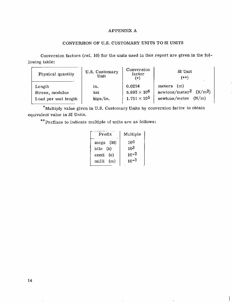
APPENDIX A
CONVERSION OF U.S. CUSTOMARY UNITS TO SI UNITS
Conversion factors (ref. 10) for the units used in this report are given in the fol-
0.02 54 6.895 X 10⁶ 1.751 X 10⁵
lowing table:
meters (m) newtons/meter2 (N/m2) newtons/meter (N/m)
Physical quantity
Length Stress, modulus Load per unit length
U.S. Customary unit
in. ksi kips/in.
Conversion factor
I (*I
SI Unit (**I
Multiply value given in U.S. Customary Units by conversion factor to obtain * equivalent value in SI Units.
Prefixes to indicate multiple of units are as follows: **
kilo (k) centi (c) milli (m)
Multiple
106 103 10-2 10-3
14
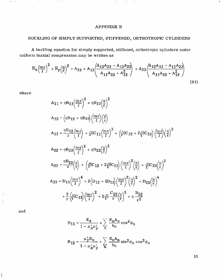
APPENDIX B
BUCKLING OF SIMPLY SUPPORTED, STIFFENED, ORTHOTROPIC CYLINDERS
A buckling equation for simply supported, stiffened, orthotropic cylinders under uniform biaxial compression may be written as
Rx(y) 2 + = A33 + A13f 12 A 23 - +A23 r 1 2 A 1 3 -- - A11:2i
AllA22 - A42 AllA22 - A12
where
and
15
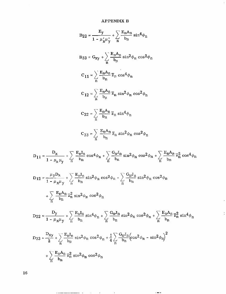
APPENDIX B
16
. . ..
APPENDIX B
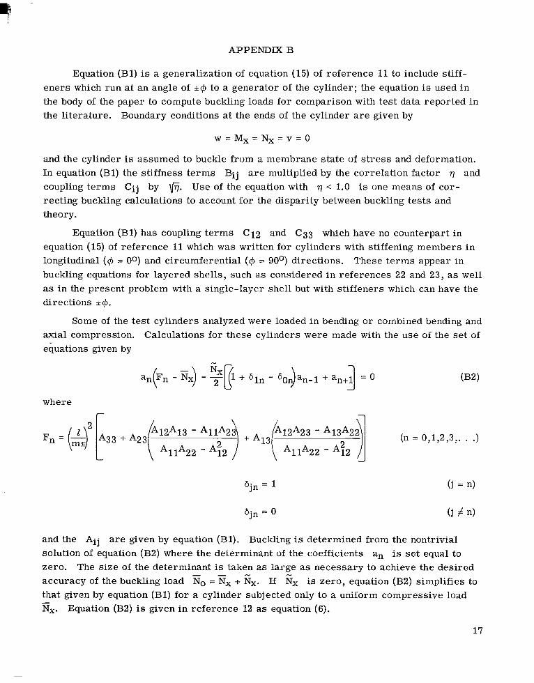
Equation (Bl) is a generalization of equation (15) of reference 11 to include stiff- eners which run at an angle of &@ to a generator of the cylinder; the equation is used in the body of the paper to compute buckling loads for comparison with tes t data reported in the literature. Boundary conditions at the ends of the cylinder are given by
and the cylinder is assumed to buckle from a membrane s ta te of stress and deformation. In equation (Bl) the stiffness t e rms B i j are multiplied by the correlation factor q and coupling t e rms Cij by \liT. U s e of the equation with < 1.0 is one means of cor- recting buckling calculations to account for the disparity between buckling tes ts and theory.
Equation (Bl) has coupling t e rms C12 and C33 which have no counterpart in
These ter ins appear in equation (15) of reference 11 which was written for cylinders with stiffening members in longitudinal (@ = 00) and circumferential (@ = 90°) directions. buckling equations for layered shells, such as considered in references 22 and 23, as wel l as in the present problem with a single-layer shell but with stiffeners which can have the directions k@.
Some of the tes t cylinders analyzed were loaded in bending o r combined bending and Calculations for these cylinders were made with the use of the set of axial compression.
equations given by
where
12 13 - A11A2) + A13 - A 1 3 A 2 j (n = 0,1,2,3,. . .) F n = ( ‘$3VA23f AllA22 A - $2 AllA22 - A?2
and the Aij are given by equation (Bl). Buckling is determined from the nontrivial solution of equation (B2) where the determinant of the coefficients an is set equal to zero. The s ize of the determinant is taken as large as necessary to achieve the desired accuracy of the buckling load No = fix + Gx. If fix is zero, equation (B2) simplifies to that given by equation (Bl) for a cylinder subjected only to a uniform compressive load Nx. -
Equation (B2) is given in reference 12 as equation (6).
17
APPENDIX C
EFFECTIVE MODULUS OF BUCKLED SKIN
In order to calculate general instability buckling loads of cylinders which experience skin buckling prior to general instability buckling, the reduced stiffness of the buckled skin must be taken into account. One way of accomplishing this is to establish by some means each of the various stiffnesses which enter into the buckling equation, but so far these stiffnesses have not been defined with sufficient accuracy to eliminate significant e r r o r s i n predictions of buckling load.
An alternate scheme consists of replacing the buckled skin in buckling calculations with an equivalent isotropic skin of reduced modulus. The value assigned to modulus is given in figure 1 which was constructed by trial and e r r o r from computations for buckling load of t h e cylinders of reference 6 with the use of assumed values for modulus for buckled skin. Ratios of Emo were sought which were consistent with those obtained in the body of this report and given in tables I to V for the tes t cylinders of references 1 to 5. not completely arbi t rary. plates i n axial compression reported in reference 24 were t r ied first, and the final curve lies between these values. correlation of Emo.
This scheme is employed herein.
The choice of t r ia l values of effective modulus was Values between the secant and tangent moduli for buckled
Sufficient additional trials were made to achieve the desired
Hopefully, the effective modulus given in figure 1 is reasonably independent of s t i f f - ener geometry and buckling mode and therefore can be generally applied with little e r ro r . A check on this premise w a s obtained by auxiliary buckling calculations for axially stiff- ened cylinders whose geometry and buckling mode differ considerably from those of the cylinders of reference 6. Buckling calculations were made for the axially stiffened cylin- de r s of reference 24 with the use of figure 1 and reference 25. Reference 25 which applies to cylinders with clamped support a t the ends of the cylinder is the counterpart of equation (Bl) for simply supported cylinders. The resulting calculations were compared with calculations made for the cylinders of reference 26 which had closely spaced string- ers and therefore experienced no local skin buckling in much the same manner as dis- cussed previously where buckling calculations for the tes t cylinders of reference 6 were compared with those of the tes t cylinders of references 1 to 5. The check indicated that effective modulus is not very sensitive to cylinder geometry and buckling mode and that the single curve of figure 1 probably gives a reasonable approxima.tion for effective stiff- ness for a wide variety of cylinder geometries. Although use of figure 1 in calculating general buckling of cylinders with ring-and-stringer stiffening entails an approximate treatment of buckled skin, the treatment is probably as accurate as state-of-the-art permits at the present time.
18
REFERENCES
1. Meyer, R. R.: Buckling of 450 Eccentric-Stiffened Waffle Cylinders. J. Roy. Aeronaut. SOC. (Tech. Notes), vol. 71, no. 679, July 1967, pp. 516-520.
2. Singer, J.: The Influence of Stiffener Geometry and Spacing on the Buckling of Axially Compressed Cylindrical and Conical Shells. Niordson, ed. , Springer-Verlag, 1969, pp. 234-263.
Theory of Thin Shells, F. I.
3. Dickson, John N.; and Brolliar, Richard H.: The General Instability of Ring-Stiffened NASA TN D-3089, 1966. Corrugated Cylinders Under Axial Compression.
4. Peterson, James P.; and Anderson, James Kent: Bending Tests of Large-Diameter Ring-Stiffened Corrugated Cylinders. NASA TN D-3336, 1966.
5. Anderson, James Kent: Bendin.g Tests of Two Large-Diameter Corrugated Cylinders With Eccentric Ring Stiffeners. NASA TN D-3702, 1966.
6. Card, Michael F. : Bending Tests of Large-Diameter Stiffened Cylinders Susceptible to General Instability. NASA TN D-2200, 1964.
7. Milligan, Roger; Gerard, George; Lakshmikanthan, C.; and Becker, Herbert: General Instability of Orthotropically Stiffened Cylinders. Torsion and Hydrostatic P res su re Loadings. Force, July 1965.
Part I - Axial Compression, AFFDL-TR-65-161, Pt. I, U.S. Air
8. Lakshmikantham, C.; Gerard, G.eorge; and Milligan, Roger: General Instability of Orthotropically Stiffened Cylinders. and Bending.
Part I1 - Bending and Combined Compression AFFDL-TR-65-161, Pt. II, U.S. Air Force, Aug. 1965.
9. Katz, Lester: Compression Tests on Integrally Stiffened Cylinders. NASA TM X-53315, 1965.
10. Comm. on Metric Pract.: ASTM Metric Pract ice Guide. NBS Handbook 102, U.S. Dep. Corn., March 10, 1967.
11. Block, David L.; Card, Michael F.; and Mikulas, Martin M., Js.: Buckling of Eccen- trically Stiffened Orthotropic Cylinders. NASA TN D-2960, 1965.
12. Block, David L. : Buckling of Eccentrically Stiffened Orthotropic Cylinders Under Pure Bending. NASA TN D-3351, 1966.
13. Dunn, Louis G.: Some Investigations of the General Instability of Stiffened Metal IX-Criterions for the Design of Stiffened Metal Cylinders Subject to Cylinders.
General Instability Failures. NACA TN 1198, 1947.
19
14. Hoff, N. J.; Fuchs, S. J.; and Cirillo, Adam J.: The Inward Bulge Type Buckling of Monocoque Cylinders. II-Experimental Investigation of the Buckling in Combined Bending and Compression. NACA TN 939, 1944.
15. Dickson, John N.; and Brolliar, Richard H.: The General Instability of Eccentrically Stiffened Cylindrical Shells Under Axial Compression and Lateral Pressure. NASA CR-1280, 1969.
16. Van der Neut, A.: Plates. Rep VTH- 113, Technische Hogeschool Delft Vliegtuigbouwkunde (Delft, Netherlands) , October 1962.
The Postbuckling Stiffness of Rectangular Simply Supported
17. Peterson, James P.: Weight-Strength Studies of Structures Representative of Fuse- lage Construction. NACA TN 4114, 1957.
18. Peterson, James P. : Correlation of the Buckling Strength of Pressurized Cylinders NASA TN D-526, 1960. in Compression or Bending With Structural Parameters .
19. Block, David L.: Influence of Discrete Ring Stiffeners and Prebuckling Deformations on the Buckling of Eccentrically Stiffened Orthotropic Cylinders. NASA TN D-4283, 1968.
20. Budiansky, Bernard; and Hutchinson, John W.: A Survey of Some Buckling Problems. AIAA J., vol. 4, no. 9, Sept. 1966, pp. 1505-1510.
21. Hutchinson, John W.; and Amazigo, John C.: Imperfection-Sensitivity of Eccentrically Stiffened Cylindrical Shells. AIAA J., vol. 5, no. 3, Mar. 1967, pp. 392-401.
22. Card, Michael F. : Experiments to Determine the Strength of Filament-Wound Cylin- NASA TN D-3522, 1966.
Buckling of Circular Cylindrical Shells With Multiple Orthotropic
d e r s Loaded in Axial Compression.
23. Jones, Robert M.: Layers and Eccentric Stiffeners. AIM J., vol. 6, no. 12, Dec. 1968, pp. 2301-2305.
24. Peterson, James P.; Whitley, Ralph 0.; and Deaton, J e r r y W.: Structural Behavior and Compressive Strength of Circular Cylinders With Longitudinal Stiffening. NASA TN D-1251, 1962.
25. Card, Michael F.; and Jones, Robert M.: Experimental and Theoretical Results for NASA T N D-3639, 1966. Buckling of Eccentrically Stiffened Cylinders.
26. Peterson, James P.; and DOW, Marvin B.: Compression Tests on Circular Cylinders Stiffened Longitudinally by Closely Spaced Z-Section Stringers. NASA MEMO 2-12-59L7 1959.
20
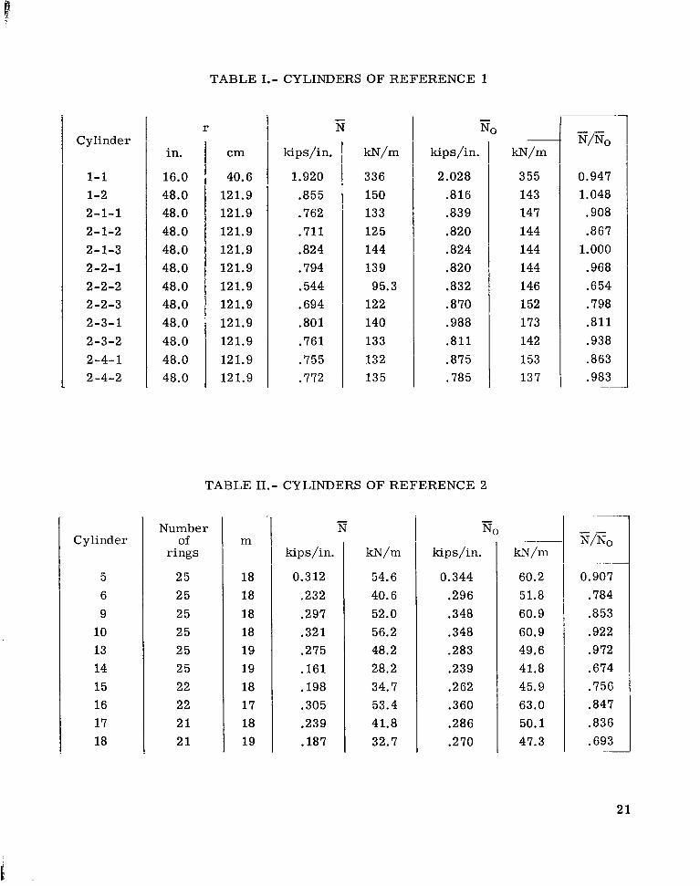
TABLE 1.- CYLINDERS OF REFERENCE 1
Cylinder
1-1 1-2 2-1-1 2-1-2 2-1-3 2-2-1 2-2-2 2-2-3 2-3-1 2-3-2 2-4-1 2-4-2
Cylinder
5 6 9
10 13 14 15 16 17 18
r
in.
16.0 48.0 48.0 48.0 48.0 48.0 48.0 48.0 48.0 48.0 48.0 48.0
cm
40.6 121.9 121.9 121.9 121.9 121.9 121.9 121.9 121.9 121.9 12 1.9 121.9
- N
kips/in.
1.920 .855 .762 .711 .824 .794 .544 .694 .801 .761 .755 .772
W m
336 150 133 12 5 144 139 95.3
122 140 133 132 135
kips/in.
2.028 .816 .839 .820 -824 .820 .832 .870 .988 .811 .875 .785
Number of
rings
25 25 25 25 25 25 22 22 2 1 2 1
TABLE 11.- CYLINDERS OF REFERENCE 2
m
18 18 18 18 19 19 18 17 18 19
- N
kips/in.
0.312 .232 .297 .321 .275 .161 .198 .305 .239 .187
m / m
54.6 40.6 52.0 56.2 48.2 28.2 34.7 53.4 41.8 32.7
kips/in.
0.344 .296 .348 .348 .283 .239 .262 .360 .286 .270
kN/m
355 143 147 144 144 144 146 152 173 142 153 137
kN/m
60.2 51.8 60.9 60.9 49.6 41.8 45.9 63.0 50.1 47.3
- - "0
0.947 1.048 .908 .867
1.000 .968 .654 .798 .811 .938 .863 .983
__
- - N/NO
0.907 .784 .853 .922 .972 .674 .756 .847 .836 .693
2 1
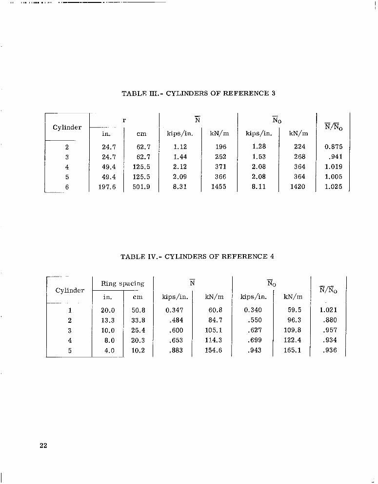
TABLE HI.- CYLINDERS OF REFERENCE 3
1.28 1.53 2.08 2.08 8.11
Cylinder
224 0.875 268 .941 3 64 1.019 3 64 1.005
1420 1.025
Cylinder
1 2 3 4 5
~- ~~.
in.
24.7 24.7 49.4 49.4
197.6
r
cm
62.7 62.7
125.5 125.5 501.9
~~~
~~
- N
kips/in.
1.12 1.44 2.12 2.09 8.31
w m
196 2 52 371 3 66
1455
TABLE 1V.- CYLINDERS OF REFERENCE 4
- NO I -
Ring spacing I N
kips/in.
0.347 .484 .600 .653 .883
w m
60.8 84.7
105.1 114.3 154.6
kips /i n.
0.340 .550 .627 .699 .943
k-N/m
59.5 96.3
109.8 122.4 165.1
" 0
1.021 .880 .957 .934 .936
22
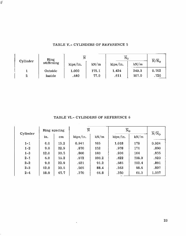
TABLE V.- CYLINDERS OF REFERENCE 5
1 l 2
i I I I I i
Outside 1.000 175.1 1.424 249.3 0.702 Inside I .440 I 77.0 I .611 107.0 1 .720
I I I I I I I I t
TABLE VI.- CYLINDERS OF REFERENCE 6
Cylinder
1- 1 1-2 1-3 2 -1 2-2 2-3 2-4
Ring spacing
in.
6.0 9.0
12.0 6.0 9.0
12.0 18.0
cm
15.2 22.9 30.5 15.2 22.9 30.5 45.7
- N
kips /in.
0.941 .870 .800 .572 .521 .505 .370
w m
165 152 140 100.2 91.2 88.4 64.8
kips /in.
1.018 .978 .936 .622 .585 .563 .350
~~ ~
kN/m
178 171 164 108.9 102.4 98.6 61.3
0.924 .890 .855 .920 .891 .897
1.057
23
0 2
.
8 10 12 14 16 18 20 22 24
Figure 1.- Effective modulus of buckled skin used in buck l ing calculat ions for stiffened cylinders.
24
- - NO
.5
.4
.3
.2
.1
r
__. -~ - -
Symbol Ref
V 1 2 0
A 3 0 4 n 5 0 6
18
____-- -
~
-
I I i I
Figure 2.- Test data on stiffened cylinders. Flagged symbols denote fa i lure by panel instabil ity.
NATIONAL AERONAUTICS AND SPACE ADMINISTRATION WASHINGTON, D. C. 20546
OFFICIAL BUSINESS FIRST CLASS MAIL
POSTAGE A N D FEES PAID NATIONAL AERONAUTICS A N D
SPACE ADMINISTRATION
POSTMASTER: If Undeliverable ( Section 158 Postal Manual) Do Not Return
-
"The nqsomiiiticnl nnd spnce cictiuities of the United Stotes shall. be coiadi/cte& -so ns t o coiztribzite . . . t o the expaizsioiz of hiininn knoiul- edge of pbeaontenn in the ntmosphese nnd spnce. T h e Adiuiuistrntioiz shnll psottide for the widest psncticnble nrzd nppioprinte disseiiiiizn!iou of inforinntioia coiiceraiiig its sctir'ities nizd the iesults theseof."
-NATIONAL AERONAUTICS AND SPACE ACT OF 1958
i NASA SCIENTIFIC AND TECHNICAL PUBLICATIONS
TECHNICAL REPORTS: Scientific and technical information considered important, complete, and a lasting contribution to existing knowledge.
TECHNICAL NOTES: Information less broad in scope but nevertheless of importance as a contribution to existing knowledge.
TECHNICAL MEMORANDUMS: Information receiving limited distribution because of preliminary data, security classifica- tion, or other reasons.
CONTRACTOR REPORTS: Scientific and technical information generated under a NASA contract or grant and considered an important contribution to existing knowledge.
TECHNICAL TRANSLATIONS: Information published in a foreign language considered to merit NASA distribution in English.
SPECIAL PUBLICATIONS: Information derived from or of value to NASA activities. Publications include conference proceedings, monographs, data compilations, handbooks, sourcebooks, and special bibliographies.
TECHNOLOGY UTILIZATION PUBLICATIONS: Information on technology iised by NASA that may be of particular in rerest in commercial and other non-aerospace npplications. Publications include Tech Briefs, Ttchnology Utilization Reports and Notes, and Technology Surveys.
Details on the availability of these publications may be obtained from:
SCIENTIFIC AND TECHNICAL INFORMATION DIVISION
NATIONAL AERONAUTICS AND SPACE ADMINISTRATION Washington, D.C. 20546