Embed Size (px)
Citation preview

2876 | Soft Matter, 2017, 13, 2876--2885 This journal is©The Royal Society of Chemistry 2017
Cite this: SoftMatter, 2017,
13, 2876
Buckling of elastomer sheets under non-uniformelectro-actuation
Hadrien Bense, * Miguel Trejo, Etienne Reyssat, Jose Bico and Benoıt Roman
Dielectric elastomer sheets undergo in-plane expansion when stimulated by a transverse electric field.
We study experimentally how dielectric plates subjected to a non-uniform voltage distribution undergo
buckling instabilities. Two different configurations involving circular plates are investigated: plates freely
floating on a bath of water, and plates clamped on a frame. We describe theoretically the out-of-plane
deformation of the plates within the framework of weakly non-linear plate equations. This study
constitutes a first step of a route to control the 3D activation of dielectric elastomers.
1 Introduction
Dielectric actuation was discovered in the 1880s by W. Rontgen,1
but practical studies have started flourishing only recently afterthe seminal work from Pelrine et al.2 In dielectric actuation, theopposing sides of a sheet of elastomer are coated with compliantelectrodes. Applying a high voltage V to this soft capacitor tendsboth to compress the membrane across its thickness and tostretch its surface (Fig. 1). In contrast with piezoelectricceramics, dielectric elastomers can undergo very high strainsof up to 500%,3 which have inspired numerous potential appli-cations ranging from bioinspired actuators4,5 to soft grippers,6,7
bearing-free motors8 or energy harvesting systems.9,10 However,dielectric elastomers are prone to electromechanical instabilitieswhen high electric fields are applied. Thinning down themembrane indeed results in higher electric fields (for a fixedapplied voltage) which amplifies the actuation and eventuallyleads to a ‘‘pull-in’’ instability and electrical breakdown.11,12 Acommon solution to avoid this destructive instability consists instrongly prestretching the membrane (up to 300%, dependingon the elastomer used). Due to the non-linear elastic properties,the polymer stiffens when prestretched, which prevents thepull-in instability. Other types of instabilities are neverthelesscommon. Impressive shape bifurcations can for instance beobserved in pressurised membranes.13–16 Harnessing bucklinginstabilities is moreover a key for many potential applicationssuch as dynamic surface patterning,17,18 flow regulation inmicro-fluidic devices,19 tuning of variable focal lenses20 orhaptic displays (e.g. Braille screens).21,22
In the present study, we propose to investigate how a non-uniform spatial distribution of the applied voltage inducesdifferent out-of-plane buckling patterns. In contrast to moststudies, buckling is here not due to the clamped edges of thepolymer, but only to the inhomogeneous actuation of themembrane. Our experiments are inspired by recent works onthe non-uniform growth of plant leaves or material swellingthat leads to complex 3D shapes.23–25 The present study thusconstitutes a first step towards 3D electrical morphing. Spectacularstrains are generally obtained by applying strong mechanicaltension prior to actuation. However, since such prestrains wouldhinder the formation of 3D shapes we do not apply any significantpre-stretch to the membrane.
We focus on model axisymmetric configurations whereactive circular domains are surrounded by passive materialswith well-defined boundary conditions. Actuation is thereforenon-homogeneous as one region is subjected to voltage whilethe rest of the membrane is not. In the first configuration,the membrane floats freely at the surface of a bath of waterthat plays the role of the counter-electrode (Fig. 2a).
Fig. 1 Principle of dielectric actuation. A membrane of the dielectricelastomer (polyvinylsiloxane) is coated with conductive powder (carbonblack) on both sides. As an electric field is applied to the membrane, theattraction between opposite charges on both sides and the repulsion ofcharges of the same sign on each side both tend to squeeze and stretchthe membrane.
Laboratoire de Physique et Mecanique des Milieux Heterogenes (PMMH), CNRS,
ESPCI Paris, PSL Research University, Sorbonne Universite, Univ. Paris Diderot.
Paris, France. E-mail: [email protected]
Received 19th January 2017,Accepted 23rd March 2017
DOI: 10.1039/c7sm00131b
rsc.li/soft-matter-journal
Soft Matter
PAPER
Publ
ishe
d on
23
Mar
ch 2
017.
Dow
nloa
ded
by U
nive
rsite
Pie
rre
et M
arie
Cur
ie o
n 11
/05/
2017
21:
21:2
3.
View Article OnlineView Journal | View Issue

This journal is©The Royal Society of Chemistry 2017 Soft Matter, 2017, 13, 2876--2885 | 2877
Nevertheless out-of-plane displacements of the membraneare limited by hydrostatic pressure. Using the analytical andnumerical tools developed for this configuration, we investi-gate a second system where the membrane is clamped in acircular horizontal frame, the sagging effect of gravity beingsuppressed by applying a pressure Dp below the membrane(Fig. 2b). In contrast with most previous studies performedon thin pre-stretched DEAs that rely on nonlinear elasticity, wewill use the weakly non-linear equations of thin elastic platesto investigate the buckled morphologies obtained with theseconfigurations.
2 Spontaneous buckling of freefloating plates2.1 Dielectric membranes
The dielectric membranes used in the experiments are made ofpolyvinyl siloxane elastomers (Elite Double 8 from Zhermack).They are obtained by spin-coating a 4 ml mix of equal quan-tities of the ‘‘catalyst’’ and ‘‘base’’ liquids on a flat wafer ofradius b = 5 cm. Using a spinning rate of 300 to 600 rpm for15 s provides membranes of thickness h ranging from 100 to300 mm. The Young’s modulus of the polymer, E = 250� 15 kPa,is estimated with a standard tensile test on a strip. Carbonblack powder is manually deposited on the surface of the curedpolymer with a brush through a circular stencil of radius a. Thepart covered with carbon black is referred to as the active part,whereas the remaining uncovered part of the membrane isdesignated as the passive part. The powder is applied until theblack colour of the patch saturates. This coating is electricallyconductive and its surface resistivity of a few hundred kO doesnot increase significantly upon additional applications ofpowder. Carbon black particles strongly adhere to the polymerso that the electrode preserves sufficient conductivity whenstretched although we observe an increase of the resistivity of500% for a typical strain of 40%. Nevertheless the resistivityrecovers its initial value when the strain is released. The relativedielectric permittivity er of PVS is accessed through a classicalelectrical measurement of the capacitance of a membrane coatedwith carbon black on both sides, leading to er = 2.5 � 0.6.
2.2 Experimental setup
Once carbon black powder has been applied on the upper face,the membrane is gently deposited at the surface of a bath ofsoapy water where it floats freely. The surface tension of purewater is 72 mN m�1 but easily drops as low as 50 mN m�1 dueto various pollutants. We deliberately add surfactants to imposea low but controlled surface tension g C 30 mN m�1 andenhance the electric conductivity of water. The voltage isimposed through a thin metallic wire (of radius of 10 mm)contacting lightly the circular electrode. The wire is connectedto a high voltage amplifier (Trek model 609 � E) driven by asignal generator, while water is connected to the electricalground and thus plays the role of a second compliant electrode.Indeed the charged carbon black electrode attracts oppositecharges until the elastomer–water interface is equivalentlycharged. Voltages applied to the system typically range from200 V to 5 kV. To measure out-of-plane deformations of themembrane, we use a laser sheet directed on the active part ofthe membrane with an oblique incidence. The deflections ofthe laser line are recorded using a camera placed above thesetup and are directly proportional to the local vertical displa-cements of the membrane (Fig. 4). Note that all experiments(including the one of Section 4) are quasistatic. The appliedvoltage is increased with steps of 100 V for every 30 s, approxi-mately. On these time scales, the response of PVS is purelyelastic. Therefore we do not expect time to play any role in ourexperiments.
Fig. 2 Experimental configurations explored in this study. In both situa-tions, the deflection of the membrane is monitored through the deviationof a laser sheet in oblique incidence. The black disk of radius a correspondsto the conductive part at the center of the pink membrane of radius b.(a) Disk floating on water. A single patch is coated on the upper side of themembrane and is connected to the generator. Water plays the role of thecounter electrode and is connected to the ground. Surfactant moleculesare added to the water to impose a fixed surface tension (of 30 mN m�1)and increase the electric conductivity of the solution. (b) Disk clamped ona circular rigid frame. Conductive domains are symmetrically coated onboth sides of the membrane. Air is gently blown from underneath tocompensate for the weight of the membrane.
Paper Soft Matter
Publ
ishe
d on
23
Mar
ch 2
017.
Dow
nloa
ded
by U
nive
rsite
Pie
rre
et M
arie
Cur
ie o
n 11
/05/
2017
21:
21:2
3.
View Article Online

2878 | Soft Matter, 2017, 13, 2876--2885 This journal is©The Royal Society of Chemistry 2017
2.3 Electro-mechanical coupling
Applying an electric voltage V across the membrane results intotwo complementary effects: charges of the same sign exert anin-plane repulsion, whereas opposite charges attract each otherthrough the thickness of the layer. Both contributions can bederived from energy considerations. The electrostatic energy of
a capacitor is1
2CV2, where C is the capacity. When the voltage V
is fixed, an external generator provides an electrical work QV,where Q = CV is the charge. The total electric energy under fixedvoltage therefore reads for a planar capacitor:
Uelec ¼1
2CV2 �QV ¼ �1
2e0erV2S
h
where e0 = 8.85 � 10�12 F m�1 is the vacuum permittivity and Sthe area of the electrode. Differentiating Uelec with respect to h(keeping S and V constant) shows that the charged electrodesapply a compressive pressure:
pelec ¼1
S
@Uelec
@h¼ 1
2e0er
V
h
� �2
Similarly, differentiating Uelec with respect to S (keeping h and Vconstant) results in a term equivalent to a negative surface tension:
2gelec ¼@Uelec
@S¼ �1
2e0er
V2
h
where the factor 2 accounts for the two coated interfaces when weextend the analogy with the tension in a soap film. Although theeffect of surface tension is generally neglected in solid mechanics,capillarity may deform very soft objects as demonstrated inflourishing recent studies.26,27
What are the consequences of pelec and gelec on a freemembrane completely covered by an electrode (such as inFig. 1)? Far from the edge, the effective negative surface tensionresults in a positive equibiaxial planar stress sr = sy = �2gelec/h.Besides, the electrical pressure leads to a compressive stressthrough the thickness, hence sz = �pelec. The stresses in themembrane are therefore given by:
sr ¼ sy ¼ �sz ¼1
2e0er
V
h
� �2
For low enough deformations (in our experiment they arealways less than 20%), linear Hooke’s law applies and leadsto the strain distribution:
er ¼ ey ¼�ez
1þ 2n¼ 1
2Ee0er
V
h
� �2
where n is the Poisson ratio of the material that constitutes themembrane.
The relevant terms of the strain tensor in setting themechanics of a thin plate are limited to in-plane components(er,ey,ery). The same in-plane strains are obtained when the plateis squeezed by a pressure �s0 and no surface tension, with
�s0 ¼1
ne0er2
V
h
� �2
(1)
This equivalent pressure �s0 = pelec/n is larger than the actualelectrostatic pressure. In the particular case of elastomers, thevalue of n is close to 1/2, and the whole strain distribution(including in this particular case the thickness strain ez) is thencorrectly reproduced by assuming that the electrostatic pressureis doubled and that there is no effect of surface tension. Thissimplifying picture is used in most studies of dielectricactuation.2,11,28 In this article, we study the case presented inFig. 2a, where the electrodes (disk with radius a) do not coverentirely the elastic membrane (disk with radius b Z a), and weshow how this configuration can lead to buckling even if theboundaries of the membrane are free. In this more generalproblem, electrostatic forces can still be replaced by an equi-valent pressure on the covering electrodes, even in non-planarsolutions, as we demonstrate in another article29 using varia-tional methods.
In the following,
e0 ¼ �nEs0 ¼
1
2Ee0er
V
h
� �2
(2)
will be called the ‘‘actuation strain’’ which is the strain that anunconstrained piece of active membrane would achieve in theabsence of external mechanical loading. Note finally that e0 canbe generalized to other types of deformations such as thermalexpansion, swelling or even biological growth.
2.4 Membrane stresses in the flat configuration: below thebuckling threshold
Using the equivalent pressure derived above, we now estimatethe strain distribution in the freely floating membrane illu-strated in Fig. 2a. As the membrane is deposited at the surfaceof water, surface tension forces tend to stretch it. The corres-ponding induced strain is g/Eh, where g is the surface tension ofwater (g C 30 mN m�1, due to the presence of a surfactant inwater), and is on the order of 10�3. For a 200 mm thickmembrane with free edges, an equivalent strain would beobtained when applying a voltage (2gh/e0er)
1/2 B 700 V. Theactual impact of surface tension is therefore significant. How-ever, the mechanics of the membrane remain linear beforebuckling. If we consider this slightly prestretched state as areference for the membrane, we should discard the effect ofsurface tension when we derive the stresses and strains inducedby the electric field. In this linear regime, both effects aresimply additive. Additivity nevertheless fails as the membranebuckles. In Section 3 the reference state is the unstrainedmembrane, and the effect of surface tension is taken intoaccount. We assume that the problem remains axisymmetricand that the membrane only undergoes in-plane deformations.Mechanical equilibrium reads:
@rsr@r� sy ¼ 0 (3)
We note u(r) the radial displacement. We impose the effectivepressure �s0 according to eqn (1) in the active domain. Using
Soft Matter Paper
Publ
ishe
d on
23
Mar
ch 2
017.
Dow
nloa
ded
by U
nive
rsite
Pie
rre
et M
arie
Cur
ie o
n 11
/05/
2017
21:
21:2
3.
View Article Online
This journal is©The Royal Society of Chemistry 2017 Soft Matter, 2017, 13, 2876--2885 | 2879
E* = E/(1 � n2), Hooke’s relation can be expressed as:
sr ¼ E� er þ neyð Þ þ n1� nsz (4)
sy ¼ E� ner þ eyð Þ þ n1� nsz; (5)
and includes sz = s0 in the active domain, and sz = 0 in thepassive zone. In the case of radial in-plane displacements, theradial and orthoradial strains are related to the radial displace-ment u(r): er = du/dr and ey = u/r, respectively. Inserting thesestrains into eqn (3) leads to the differential equation, validseparately in both active and passive regions:
r2u00 + ru0 � u = 0. (6)
where the symbol .0 stands for the derivative with respect to r.Solutions of Lame’s equations30,31 are of the form u(r) = ar + b/r,where the coefficients can be different in the active ‘‘A’’ (r o a)and passive ‘‘P’’ (a o r o b) zones and should be determined bymatching the different boundary conditions.
We enforce the continuity of u(r) and of sr(r) (equilibriumcondition) at the boundary r = a. The 1/r term should not bepresent in the active zone because of its divergence for r = 0.As a result, stresses and strains are equibiaxial in this region(er = ey = a when u = ar). Finally, this stress induced by activationvanishes at r = b in the case of a freely floating membrane.Using these four conditions, we determine the correspondingconstants a, b in both regions. We obtain in the active regionthe following displacement, strains and stresses:
uAðrÞ ¼ e0
2ð1� nÞ a2
b2þ 1þ n1� n
� �r
leading to
eAr ¼ eAy ¼e0
2ð1� nÞ a2
b2þ 1þ n1� n
� �4 0
and
sAr ¼ sAy ¼ ns02
1� a2
b2
� �o 0
In this area, strains are extensional, but lower than e0, andstresses are compressive. Indeed, constraining the deformationof the active zone by a passive one logically results intocompressive stresses. Similarly, the state of the passive zoneis given by:
uPðrÞ ¼ e0a2
2ð1� nÞ r
b2þ ð1þ nÞ
r
� �
so that:
sPr ¼ ns02
a2
b2b2
r2� 1
� �o 0
sPy ¼ �ns02
a2
b21þ b2
r2
� �4 0
In this passive region, the radial stress is compressive, whereasthe orthoradial stress is tensile, both stresses decaying away
from the active patch (note the strong discontinuity in orthoradialstress and in radial strain at the boundary r = a).
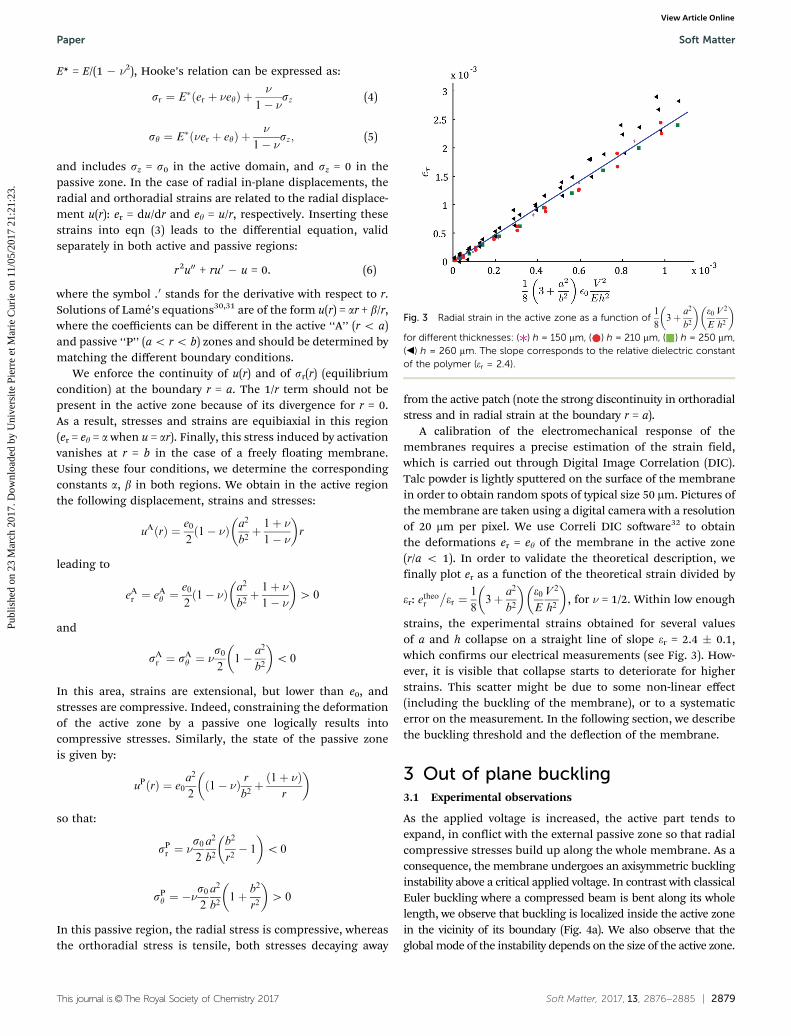
A calibration of the electromechanical response of themembranes requires a precise estimation of the strain field,which is carried out through Digital Image Correlation (DIC).Talc powder is lightly sputtered on the surface of the membranein order to obtain random spots of typical size 50 mm. Pictures ofthe membrane are taken using a digital camera with a resolutionof 20 mm per pixel. We use Correli DIC software32 to obtainthe deformations er = ey of the membrane in the active zone(r/a o 1). In order to validate the theoretical description, wefinally plot er as a function of the theoretical strain divided by
er: etheor
�er ¼
1
83þ a2
b2
� �e0E
V2
h2
� �, for n = 1/2. Within low enough
strains, the experimental strains obtained for several valuesof a and h collapse on a straight line of slope er = 2.4 � 0.1,which confirms our electrical measurements (see Fig. 3). How-ever, it is visible that collapse starts to deteriorate for higherstrains. This scatter might be due to some non-linear effect(including the buckling of the membrane), or to a systematicerror on the measurement. In the following section, we describethe buckling threshold and the deflection of the membrane.
3 Out of plane buckling3.1 Experimental observations
As the applied voltage is increased, the active part tends toexpand, in conflict with the external passive zone so that radialcompressive stresses build up along the whole membrane. As aconsequence, the membrane undergoes an axisymmetric bucklinginstability above a critical applied voltage. In contrast with classicalEuler buckling where a compressed beam is bent along its wholelength, we observe that buckling is localized inside the active zonein the vicinity of its boundary (Fig. 4a). We also observe that theglobal mode of the instability depends on the size of the active zone.
Fig. 3 Radial strain in the active zone as a function of1
83þ a2
b2
� �e0E
V2
h2
� �
for different thicknesses: ( ) h = 150 mm, ( ) h = 210 mm, ( ) h = 250 mm,(b) h = 260 mm. The slope corresponds to the relative dielectric constantof the polymer (er = 2.4).
Paper Soft Matter
Publ
ishe
d on
23
Mar
ch 2
017.
Dow
nloa
ded
by U
nive
rsite
Pie
rre
et M
arie
Cur
ie o
n 11
/05/
2017
21:
21:2
3.
View Article Online

2880 | Soft Matter, 2017, 13, 2876--2885 This journal is©The Royal Society of Chemistry 2017
Rising the voltage beyond the buckling threshold induces anincrease of the amplitude but does not modify this mode (Fig. 4b).
The deflection of the membrane is limited by its bendingrigidity and also by the hydrostatic pressure of the underneathwater. As in other systems involving compressed floating sheets,we expect buckling modes to be dictated by a competitionbetween bending stiffness and gravity.33,34 Balancing both effects
leads to an elastogravity length scale, ‘eg ¼ 2pEh3
12 1� n2ð Þrg
� �1=4
,
which sets the wavelength of the incipient buckling mode of along 1D strip floating on water. For a typical membrane ofthickness h = 200 mm, we obtain leg E 1.4 cm. In Fig. 4a, weuse leg as a scale bar. We observe that the buckling pattern islocalized and the width of the corresponding annulus is compar-able with this length scale for a c leg. Conversely, the deforma-tion involves the whole diameter of the active zone for lowervalues of a. To assess the onset of the buckling threshold and itsevolution, we monitor the profile as a function of the appliedvoltage (Fig. 4b). We characterize this actuation by the actuationstrain e0 (see eqn (2)) that we compare with the critical compres-sive strain leading to the buckling of a long 1D strip lying on
water, e1D ¼rgh 1� n2� �3E
� �1=2
¼ 2p2
3
h
‘eg
� �2
. Results are dis-
played as dots in Fig. 5. The evolution of the amplitude is notas sharp as in the case of a classical pitchfork transition that wewould expect for the buckling of the membrane. We interpret thissmoother transition as a consequence of imperfections, due forinstance to a slight deformation of the membrane caused by itscontact with the wire and to the possible migration of chargesoutside the active region. A critical applied voltage (i.e. a criticalactuation strain in the graph) for the buckling threshold cannevertheless be estimated. In the following section we develop thenon-linear equations describing this electro-activated buckling.
3.2 Non-linear equations for the buckled state
We now describe the buckling and post-buckling evolution ofthe system, using axisymmetric weakly non-linear plate equa-tions. Because strains remain low in our experiments, we willconsider the whole system as a plate with a uniform thickness.We also follow the assumption of Foppl–Von Karman plateequations which considers that out-of-plane displacement w(r)is coupled to in-plane strains.30 We first write the equilibriumof membrane stresses in the frame of reference of the plate,assuming that the slope is small (w0{ 1). The radial strain nowreads er = u0 + w02/2, while ey = u/r remains unchanged. UsingHooke’s relations (eqn (4) and (5)), in-plane equilibrium ineqn (3) now leads to:
r2u00 þ ru0 � uþ 1� n2
rw02 þ r2w0w00 ¼ 0: (7)
Fig. 4 (a) Different buckling profiles at V = 5 kV and h = 210 mm, fordifferent radii of the active zone (from left to right: a = 0.5 cm, a = 1 cm,a = 3 cm). The upper row is a picture of the membrane taken from above,while the lower one highlights the profile of the membrane. Scale bar:
elastogravity length scale ‘eg ¼ 2pEh3
12 1� n2ð Þrg
� �1=4
� 1:4 cm. (b) Super-
position of laser profiles obtained for increasing applied voltage (from0 kV to 5 kV, h = 210 mm, a = 1.5 cm). While the amplitude of the instabilityincreases progressively, the global buckling mode remains the same.
Fig. 5 Maximal amplitude A of the deflection normalized by leg asa function of the applied voltage characterised by e0/e1D. Experimentaldata (circles) are compared to numerical integration of eqn (7) and (8)(continuous line) for a membrane of thickness 200 mm. We did not use anyfitting parameter. Inset: Superposition of numerical (blue) and experi-mental (red) profiles at the point indicated by the arrow. (a) a = 6 mm,(b) a = 30 mm.
Soft Matter Paper
Publ
ishe
d on
23
Mar
ch 2
017.
Dow
nloa
ded
by U
nive
rsite
Pie
rre
et M
arie
Cur
ie o
n 11
/05/
2017
21:
21:2
3.
View Article Online
This journal is©The Royal Society of Chemistry 2017 Soft Matter, 2017, 13, 2876--2885 | 2881
which is valid separately in the active and in the passive zone.The second equation accounts for the torque balance of theplate, which in this axisymmetric case reads:35
DD2w ¼ Nrw00 þNy
w0
rþ q (8)
where D ¼ Eh3
12 1� n2ð Þ is the flexural rigidity, and Nr = hsr and
Ny = hsy are the in-plane forces per unit length, which containthe electrical actuation, since they derive from eqn (4) and (5).The last term q = �rgw corresponds to the hydrostatic pressureof the lifted water. In addition to the boundary conditionsmentioned in the previous section, 4 other conditions have tobe implemented to solve the non-linear coupled differentialeqn (7) and (8).34 Symmetry imposes w0(0) = w00 0(0) = 0. Theeffect of surface tension is taken into account through in-planestresses applied as boundary conditions. At the edge of themembrane, the radial tension balances the surface tension ofwater Nr(b) = g and in the absence of momentum the curvaturealong the radial direction vanishes, w00(0) = 0. We solve thesecoupled system equations using the bvp4c routine from Matlab.
3.3 Numerical results versus experiments
For high enough loads, out-of-plane equilibrium profiles of themembrane are obtained. We represent in the inset of Fig. 5 theprofiles calculated (without any adjustable parameter) forthe highest values of e0 achieved experimentally: V = 4000 V,i.e. e0 = 1.7 � 10�2 for a = 6 mm and V = 5000 V, i.e. e0 =2.7 � 10�2 for a = 30 mm. Both profiles are non-dimensionalizedby leg and compared with the corresponding experimentalprofiles (in red). The agreement between experiments andnumerical calculations is fairly good although the small oscilla-tions predicted for the wider active zone are not perfectlyobserved in the experiment. We interpret this minor discrepancyas a consequence of slight inhomogeneities of the membrane.We determine the maximum amplitude of the calculated profilefor decreasing loads and compare it to the experimental data(Fig. 5). Although the numerical estimation reasonably matchesthe experimental data, the predicted transition to the out-of-plane state is sharper than the experimental one as we wouldexpect for a perfect bifurcation instability.
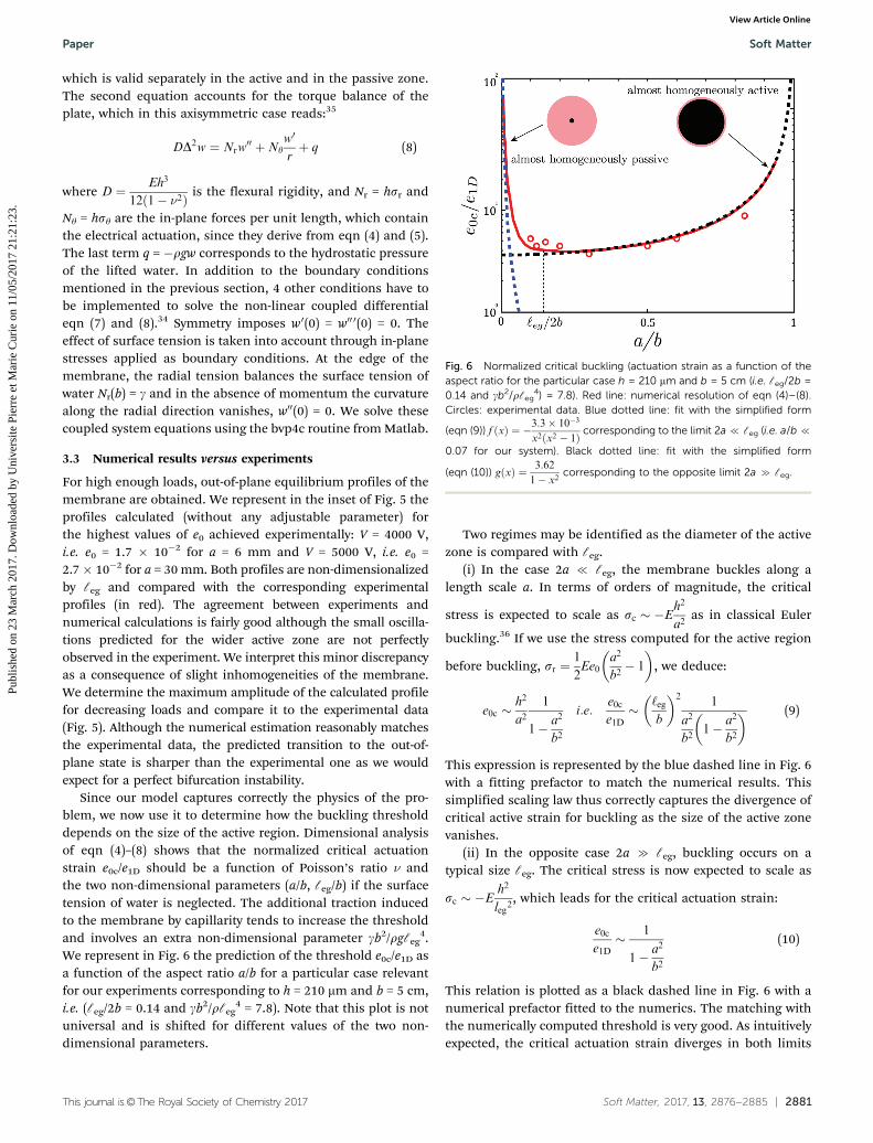
Since our model captures correctly the physics of the pro-blem, we now use it to determine how the buckling thresholddepends on the size of the active region. Dimensional analysisof eqn (4)–(8) shows that the normalized critical actuationstrain e0c/e1D should be a function of Poisson’s ratio n andthe two non-dimensional parameters (a/b, leg/b) if the surfacetension of water is neglected. The additional traction inducedto the membrane by capillarity tends to increase the thresholdand involves an extra non-dimensional parameter gb2/rgleg
4.We represent in Fig. 6 the prediction of the threshold e0c/e1D asa function of the aspect ratio a/b for a particular case relevantfor our experiments corresponding to h = 210 mm and b = 5 cm,i.e. (leg/2b = 0.14 and gb2/rleg
4 = 7.8). Note that this plot is notuniversal and is shifted for different values of the two non-dimensional parameters.
Two regimes may be identified as the diameter of the activezone is compared with leg.
(i) In the case 2a { leg, the membrane buckles along alength scale a. In terms of orders of magnitude, the critical
stress is expected to scale as sc � �Eh2
a2as in classical Euler
buckling.36 If we use the stress computed for the active region
before buckling, sr ¼1
2Ee0
a2
b2� 1
� �, we deduce:
e0c �h2
a21
1� a2
b2
i:e:e0c
e1D� ‘eg
b
� �21
a2
b21� a2
b2
� � (9)
This expression is represented by the blue dashed line in Fig. 6with a fitting prefactor to match the numerical results. Thissimplified scaling law thus correctly captures the divergence ofcritical active strain for buckling as the size of the active zonevanishes.
(ii) In the opposite case 2a c leg, buckling occurs on atypical size leg. The critical stress is now expected to scale as
sc � �Eh2
leg2, which leads for the critical actuation strain:
e0c
e1D� 1
1� a2
b2
(10)
This relation is plotted as a black dashed line in Fig. 6 with anumerical prefactor fitted to the numerics. The matching withthe numerically computed threshold is very good. As intuitivelyexpected, the critical actuation strain diverges in both limits
Fig. 6 Normalized critical buckling (actuation strain as a function of theaspect ratio for the particular case h = 210 mm and b = 5 cm (i.e. leg/2b =0.14 and gb2/rleg
4) = 7.8). Red line: numerical resolution of eqn (4)–(8).Circles: experimental data. Blue dotted line: fit with the simplified form
(eqn (9)) f ðxÞ ¼ �3:3� 10�3
x2 x2 � 1ð Þ corresponding to the limit 2a { leg (i.e. a/b {
0.07 for our system). Black dotted line: fit with the simplified form
(eqn (10)) gðxÞ ¼ 3:62
1� x2corresponding to the opposite limit 2a c leg.
Paper Soft Matter
Publ
ishe
d on
23
Mar
ch 2
017.
Dow
nloa
ded
by U
nive
rsite
Pie
rre
et M
arie
Cur
ie o
n 11
/05/
2017
21:
21:2
3.
View Article Online

2882 | Soft Matter, 2017, 13, 2876--2885 This journal is©The Royal Society of Chemistry 2017
a - 0 and a - b, where the system is almost homogeneous. Inthe first limit, stronger stresses are required as smaller buck-ling lengths are considered. Conversely, buckling tends to besuppressed as the constraining role of the passive zone getsrelatively weaker. We note finally that the buckling threshold isnearly constant in the range leg/2 o a o 0.7b, ec C 0.5e1D. Inthis limit, the compressive stresses due to activation are indeedon the order of sr B Ee0 (independently of a/b), and have tomatch the critical buckling stress sc B Ee1D. Our experimentaldata lie mostly in this regime (circles in Fig. 6). They are infair agreement with these predictions without any adjustableparameter.
4 Buckling of clamped plates
The previous floating free configuration is interesting as amodel case since the different physical ingredients leading tothe buckling instability can be precisely quantified. However,most practical applications involve a membrane held on aframe. In this section, we study the buckling of a clampedmembrane, subjected to a non homogeneous voltage distribution.In contrast with many studies from the literature conducted withhighly prestretched membranes,2,37 we tried to limit prestress asmuch as possible. We will nevertheless evaluate how slightresidual stresses may modify significantly the mechanical beha-viour of the membrane.
4.1 Experimental set-up and preliminary observations
The membranes are prepared following the same procedure asin the previous configuration. Opposite conductive patches ofradius a are now coated on each side of the membrane. In orderto limit possible strains due to the manipulation of themembrane during the framing step, we lay an annulus cut inthick paper on the spin-coated layer before curing. The liquidpolymer penetrates the paper, which enhances the adhesionof the cured membrane on the flexible paper frame. Thereinforced membrane can then be peeled and manipulatedwithout inducing additional strain. The polymeric sheet isfinally clamped in a rigid acrylic frame with a circular openingof radius b = 5 cm and held horizontally. The membrane wouldtend to sag over its own weight leading to an induced strain onthe order of (rpgR/E)2/3 B 2.5 � 10�2, where rp is the density ofthe polymer. This strain is large compared with the typicalbuckling strain, as we will see. Therefore, in order to compen-sate for this additional tension, we gently blow air from under-neath. The pressure of this air cushion is tuned until the profileof the membrane monitored with the laser sheet appearsuniformly flat (Fig. 2b). First experimental observations showthat buckling occurs beyond a critical voltage that decreases aswider active domains are considered. We also observe that thebuckled profiles obtained with this configuration take theaxisymmetric shape of a dome localised in the active region.In the following section we compare the observed profiles withthe theoretical framework adapted from the previous freefloating configuration.
4.2 Theoretical buckling in the clamped membranes
The equations dictating the shape of the membrane are thesame as in the previous configuration. In the absence ofhydrostatic pressure, the q term in eqn (8) now vanishes.Clamping the membrane in a frame also modifies the boundaryconditions: u(r = b) = w(r = b) = w0(r = b) = 0. Using theseequations, we calculate the critical buckling actuation strain e0c
for values of a/b ranging from 0.01 to 1. This last case corre-sponds to the classical derivation from Timoshenko:36
e0c ’14:7
12 1� n2ð Þh2
a2’ 0:82
h2
a2. We thus represent in Fig. 7 the
value of e0c normalized by (h/a)2 as a function of a/b. The datafrom the numerics are well represented by an empirical relation:
e0c ¼h2
a20:27þ 0:56
a
b
� �(11)
Counter-intuitively, buckling is relatively easier for a smallpatch than for a wider one. Indeed, out of plane deformation isnot strictly bound to the active zone and can also involve part ofthe passive one, leading to a lower buckling threshold.
The buckling actuation strain measured in our experimentsis however 5 to 100 times higher than expected from thesenumerical calculations (Fig. 8). We interpret this significantshift as due to the prestrain induced during the curingstage.38 We estimate this strain through DIC by comparinga membrane initially clamped to a paper frame and thenreleased. We evidence a prestrain ep on the order of2 � 10�3, which is large in comparison with typical valuespredicted for the buckling strain (e0c B 10�3). As a conclusion,although the paper frame limits additional non-uniform pre-strains due to the manipulation of the membrane, a uniformprestrain is still present in the samples. In the followingsection, we therefore include an initial extensional prestrainep in the calculation to better capture the features experimen-tally observed.
Fig. 7 Numerical prediction of the normalized critical buckling straine0ca2/h2 as a function of the aspect ratio a/b, for a clamped plate, in theabsence of gravity or prestrain. The data are well fitted by a linear
regression: e0c ¼h2
a20:27þ 0:56
a
b
� �. For a = b, we recover Timoshenko’s
classical result e0c � 0:83h2
a2for the buckling of a clamped disk.
Soft Matter Paper
Publ
ishe
d on
23
Mar
ch 2
017.
Dow
nloa
ded
by U
nive
rsite
Pie
rre
et M
arie
Cur
ie o
n 11
/05/
2017
21:
21:2
3.
View Article Online
This journal is©The Royal Society of Chemistry 2017 Soft Matter, 2017, 13, 2876--2885 | 2883
4.3 Comparison of the amplitude and the mode shape
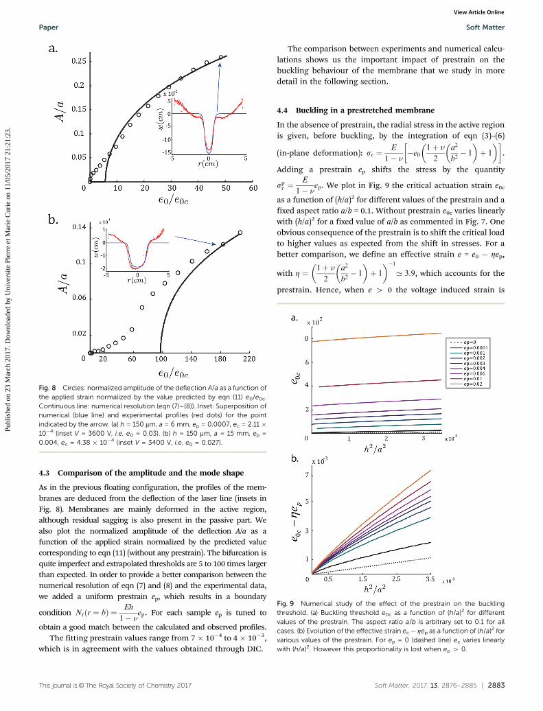
As in the previous floating configuration, the profiles of the mem-branes are deduced from the deflection of the laser line (insets inFig. 8). Membranes are mainly deformed in the active region,although residual sagging is also present in the passive part. Wealso plot the normalized amplitude of the deflection A/a as afunction of the applied strain normalized by the predicted valuecorresponding to eqn (11) (without any prestrain). The bifurcation isquite imperfect and extrapolated thresholds are 5 to 100 times largerthan expected. In order to provide a better comparison between thenumerical resolution of eqn (7) and (8) and the experimental data,we added a uniform prestrain ep, which results in a boundary
condition Nrðr ¼ bÞ ¼ Eh
1� nep. For each sample ep is tuned to
obtain a good match between the calculated and observed profiles.The fitting prestrain values range from 7 � 10�4 to 4 � 10�3,
which is in agreement with the values obtained through DIC.
The comparison between experiments and numerical calcu-lations shows us the important impact of prestrain on thebuckling behaviour of the membrane that we study in moredetail in the following section.
4.4 Buckling in a prestretched membrane
In the absence of prestrain, the radial stress in the active regionis given, before buckling, by the integration of eqn (3)–(6)
(in-plane deformation): sr ¼E
1� n �e01þ n2
a2
b2� 1
� �þ 1
� � .
Adding a prestrain ep shifts the stress by the quantity
spr ¼E
1� nep. We plot in Fig. 9 the critical actuation strain e0c
as a function of (h/a)2 for different values of the prestrain and afixed aspect ratio a/b = 0.1. Without prestrain e0c varies linearlywith (h/a)2 for a fixed value of a/b as commented in Fig. 7. Oneobvious consequence of the prestrain is to shift the critical loadto higher values as expected from the shift in stresses. For abetter comparison, we define an effective strain e = e0 � Zep,
with Z ¼ 1þ n2
a2
b2� 1
� �þ 1
� ��1’ 3:9, which accounts for the
prestrain. Hence, when e 4 0 the voltage induced strain is
Fig. 8 Circles: normalized amplitude of the deflection A/a as a function ofthe applied strain normalized by the value predicted by eqn (11) e0/e0c.Continuous line: numerical resolution (eqn (7)–(8)). Inset: Superposition ofnumerical (blue line) and experimental profiles (red dots) for the pointindicated by the arrow. (a) h = 150 mm, a = 6 mm, ep = 0.0007, ec = 2.11 �10�4 (inset V = 3600 V, i.e. e0 = 0.03). (b) h = 150 mm, a = 15 mm, ep =0.004, ec = 4.38 � 10�4 (inset V = 3400 V, i.e. e0 = 0.027).
Fig. 9 Numerical study of the effect of the prestrain on the bucklingthreshold. (a) Buckling threshold e0c as a function of (h/a)2 for differentvalues of the prestrain. The aspect ratio a/b is arbitrary set to 0.1 for allcases. (b) Evolution of the effective strain ec� Zep as a function of (h/a)2 forvarious values of the prestrain. For ep = 0 (dashed line) ec varies linearlywith (h/a)2. However this proportionality is lost when ep 4 0.
Paper Soft Matter
Publ
ishe
d on
23
Mar
ch 2
017.
Dow
nloa
ded
by U
nive
rsite
Pie
rre
et M
arie
Cur
ie o
n 11
/05/
2017
21:
21:2
3.
View Article Online

2884 | Soft Matter, 2017, 13, 2876--2885 This journal is©The Royal Society of Chemistry 2017
compressive enough to compensate for the initial prestrain.The plots of effective strain at buckling as a function of h2/a2 donot collapse on a same master curve and the linear dependencewith (h/a)2 is lost. The effect of prestrain is therefore not simplyadditive. Indeed, the stresses induced by the electrostaticloading are not equi-biaxial in the passive part of themembrane, and therefore do not simply compensate the prestress.This effect is modest in the present case, however practicalapplications can involve highly prestretched membranes to avoidpull-in instabilities. Although exploring the non-linear elasticdomain is beyond the scope of the current work, we highlightedthe fact that the consequences of prestrain in activatedmembranes are non-trivial.
4.5 Secondary buckling bifurcation
So far, our experiments were restricted to the limit of small slopesw0 { 1, i.e. to moderate applied loads. Although non-linearbuckling instabilities were observed, axisymmetry was maintainedin the observed patterns. An interesting secondary instability ishowever observed in the last case of membranes held on a rigidframe. Beyond a second critical voltage, azimuthal wrinklesappear at the border of the active zone (Fig. 10). Within the rangeof our experimental parameters (V is limited to 5 kV), thesewrinkles are only observed for sufficiently large active patches(typically a 4 1.5 cm for h = 150 mm). Provided that the prestrainin the membrane is sufficiently homogeneous (and low), theirwavelength is well-defined and does not evolve significantly withthe applied voltage. We did not observe the secondary instabilitywith the membrane floating on water, presumably because wewere not able to reach higher voltages with our setup. Theobserved pattern is very reminiscent of the wrinkles observedwhen inflating a mylar balloon39 or at the edges of a very thinsheet deposited at the curved surface of a droplet of water.40
Similar wrinkles have been reported in dielectric polymers as the
load is released after a very high deformation.14 Such wrinkles arethe consequence of compressive orthoradial stresses. Numericalcalculations of the azimuthal stress sy indeed show the presenceof high compressive stress at the edges of the active zone. Never-theless the description of the buckling threshold and the value ofthe observed wavelength still remain open questions.
5 Concluding remarks
We have shown in this study how a non-uniform voltagedistribution can trigger buckling instabilities in free floating,or clamped dielectric elastomeric sheets. In the first configu-ration, the interplay between hydrostatics and the bendingstiffness of the membrane provides a length scale to theproblem. If the diameter of the active zone is large in compar-ison with this elastogravity length, the buckling is localized inthe vicinity of the border of the active zone. The typical width ofthe wrinkles is then set by the elastogravity length. In theopposite situation, a dimple is formed at the center of thebuckled active zone. We find that the instability is favored(lower threshold) when actuation is truly heterogeneous:almost fully active or fully passive configuration is less proneto buckling (see Fig. 6).
In the second configuration the membrane is clamped in aframe. In the absence of gravity, the relevant length scalebecomes the size of the system and more specifically, thediameter of the active zone. A first bifurcation then leads tothe out-of-plane buckling of the active zone into an axisymmetricdome. For higher voltages, we observe a secondary instability:azimuthal wrinkles appear at the border of the active zone andgrow as the voltage is further increased. In both configurations,buckling mechanics can be captured by solving the Foppl–VonKarman equations in which the electrical effect is renderedthrough an ‘‘actuation’’ strain proportional to the square ofthe applied voltage. We validated this numerical approach witha fair comparison with our experimental results. Using this tool,we could study in detail the effect of a small prestrain in thebuckling behaviour of the membranes. However, further workwill probably be necessary to extend our study to the very largeprestrain applied in many studies.
We believe that our results constitute a first step towards theuse of dielectric elastomers as model systems to study mechanicalinstabilities triggered by non-uniform in-plane actuation.Applying a voltage modifies the metrics of the dielectricmembrane in the same manner as thermal expansion, swellingor biological growth would. In terms of applications, suchactuators could be used to obtain 3D shapes through electro-mechanical instabilities.
Acknowledgements
This work was partially funded by the Interuniversity Attrac-tion Poles Programme (IAP 7/38 MicroMAST) initiated by theBelgian Science Policy Office and the French ANR SMArT.
Fig. 10 Secondary instability leading to regular azimuthal wrinkles nearthe edges of the active region (a = 3 cm, h = 150 mm, V = 5 kV).
Soft Matter Paper
Publ
ishe
d on
23
Mar
ch 2
017.
Dow
nloa
ded
by U
nive
rsite
Pie
rre
et M
arie
Cur
ie o
n 11
/05/
2017
21:
21:2
3.
View Article Online
This journal is©The Royal Society of Chemistry 2017 Soft Matter, 2017, 13, 2876--2885 | 2885
We thank Bruno Secordel for his initial experiments withdielectric membranes that lead to this study.
References
1 C. Keplinger, M. Kaltenbrunner, N. Arnold and S. Bauer,Proc. Natl. Acad. Sci. U. S. A., 2010, 107, 4505–4510.
2 R. Pelrine, R. Kornbluh, Q. Pei and J. Joseph, Science, 2000,287, 836–839.
3 J. Huang, T. Li, C. Chiang Foo, J. Zhu, D. R. Clarke andZ. Suo, Appl. Phys. Lett., 2012, 100, 041911.
4 F. Carpi and D. D. Rossi, Bioinspiration Biomimetics, 2007, 2,S50–S63.
5 F. Carpi, G. Frediani, S. Turco and D. De Rossi, Adv. Funct.Mater., 2011, 21, 4152–4158.
6 O. A. Araromi, I. Gavrilovich, J. Shintake, S. Rosset, M. Richard,V. Gass and H. R. Shea, ASME Transactions on Mechatronics,2015, 20, 438–446.
7 J. Shintake, S. Rosset, B. Schubert, D. Floreano and H. Shea,Adv. Mater., 2016, 28, 231–238.
8 B. M. O’Brien, E. P. Calius, T. Inamura, S. Q. Xie and I. A.Anderson, Appl. Phys. A: Mater. Sci. Process., 2010, 100, 385–389.
9 C. Foo, S. J. A. Koh, C. Keplinger, R. Kaltseis, S. Bauer andZ. Suo, J. Appl. Phys., 2012, 111, 094107.
10 J. Huang, S. Shian, Z. Suo and D. R. Clarke, Adv. Funct.Mater., 2013, 23, 5056–5061.
11 Z. Suo, Acta Mech. Solida Sin., 2010, 23, 549–578.12 J. Zhu, M. Kollosche, T. Lu, G. Kofod and Z. Suo, Soft Matter,
2012, 8, 8840–8846.13 C. Keplinger, T. Li, R. Baumgartner, Z. Suo and S. Bauer,
Soft Matter, 2012, 8, 285–288.14 G. Mao, X. Huang, M. Diab, T. Li, S. Qu and W. Yang,
Soft Matter, 2015, 11, 6569–6575.15 X. Liang and S. Cai, J. Appl. Mech., 2015, 82, 101002.16 H. Zhao, J. Zhao, J.-W. Zha, Z.-F. Zhang, D.-R. Wang and
Z.-M. Dang, J. Adv. Phys., 2013, 2, 13–19.17 Q. Wang and X. Zhao, Phys. Rev. E: Stat., Nonlinear, Soft
Matter Phys., 2013, 88, 042403.18 X. Zhao and Q. Wang, Appl. Phys. Rev., 2014, 1, 021304.19 B. Tavakol, M. Bozlar, C. Punckt, G. Froehlicher, H. A. Stone,
I. A. Aksay and D. P. Holmes, Soft Matter, 2014, 10, 4789–4794.20 S.-i. Son, D. Pugal, T. Hwang, H. R. Choi, J. C. Koo, Y. Lee,
K. Kim and J.-D. Nam, Appl. Opt., 2012, 51, 2987–2996.
21 P. Chakraborti, H. K. Toprakci, P. Yang, N. Di Spigna,P. Franzon and T. Ghosh, Sens. Actuators, A, 2012, 179,151–157.
22 S. Vishniakou, B. W. Lewis, X. Niu, A. Kargar, K. Sun,M. Kalajian, N. Park, M. Yang, Y. Jing, P. Brochu, Z. Sun,C. Li, T. Nguyen, Q. Pei and D. Wang, Sci. Rep., 2013,3, 2521.
23 J. Dervaux and M. Ben Amar, Phys. Rev. Lett., 2008,101, 068101.
24 Z. L. Wu, M. Moshe, J. Greener, H. Therien-Aubin, Z. Nie,E. Sharon and E. Kumacheva, Nat. Commun., 2013, 4, 1586.
25 J. Kim, J. A. Hanna, M. Byun, C. D. Santangelo andR. C. Hayward, Science, 2012, 335, 1201–1205.
26 E. R. Jerison, Y. Xu, L. A. Wilen and E. R. Dufresne,Phys. Rev. Lett., 2011, 106, 186103.
27 S. Karpitschka, A. Pandey, L. A. Lubbers, J. H. Weijs,L. Botto, S. Das, B. Andreotti and J. H. Snoeijer, Proc. Natl.Acad. Sci. U. S. A., 2016, 113, 7403–7407.
28 P. Ronald, K. Roy and J. Jose, Sens. Actuators, A, 1998, 64,77–85.
29 H. Bense, B. Roman, J. Bico and B. Andreotti, in prep., 2017.30 S. Timoshenko and S. Woinowsky-Krieger, Theory of plates
and shells, McGraw-Hill, 2nd edn, 1959.31 B. Audoly and Y. Pomeau, Elasticity and Geometry: From hair
curls to the non-linear response of shells, OUP Oxford, 2010.32 http://www.correli-stc.com/.33 L. Pocivavsek, R. Dellsy, A. Kern, S. Johnson, B. Lin,
K. Y. C. Lee and E. Cerda, Science, 2008, 320, 912–916.34 M. Pineirua, N. Tanaka, B. Roman and J. Bico, Soft Matter,
2013, 9, 10985–10992.35 E. H. Mansfield, The bending and stretching of plates,
Cambridge university press, 1989.36 S. Timoshenko and J. Gere, Theory of elastic stability, Dover,
2nd edn, 1961.37 S. Bauer, S. Bauer-Gogonea, I. Graz, M. Kaltenbrunner,
C. Keplinger and R. Schwodiauer, Adv. Mater., 2014, 26,149–162.
38 Y. Xia and G. M. Whitesides, Annu. Rev. Mater. Sci., 1998, 28,550–575.
39 W. H. Paulsen, The American Mathematical Monthly, 1994,101, 953–958.
40 H. King, R. D. Schroll, B. Davidovitch and N. Menon,Proc. Natl. Acad. Sci. U. S. A., 2012, 109, 9716–9720.
Paper Soft Matter
Publ
ishe
d on
23
Mar
ch 2
017.
Dow
nloa
ded
by U
nive
rsite
Pie
rre
et M
arie
Cur
ie o
n 11
/05/
2017
21:
21:2
3.
View Article Online


![Silicone rubbers for dielectric elastomers with improved ......dielectric elastomer (DE) formulation due to their favorable electro-mechanical properties. [1] Dielectric elastomers](https://img.pdfslide.us/doc/110x75/60a7aa8430c09b569000940a/silicone-rubbers-for-dielectric-elastomers-with-improved-dielectric-elastomer.jpg)