Embed Size (px)
Citation preview

Buckling behaviour of graphene sheets
Andre Lourenco Marques Martins [email protected]
Instituto Superior Tecnico, Universidade de Lisboa, Portugal
November 2016
Abstract
Graphene is a single layer of carbon atoms, in an hexagonal lattice, and one of the most interestingnano-structures of today, given its excellent mechanical, electrical and optical properties, withapplications in almost every field of engineering. Taking this into account, this work aims to builda finite element model of a graphene sheet that allows the study of its structural stability, verifyingthis model with results from other investigators. This model was built following the atomic-continuumapproach, using the AMBER inter-atomic potential. This work also shows a parametric study ofthe buckling of graphene sheets for different combinations of loads and supports, making a criticalassessment of the variation of the buckling load and the corresponding buckling mode with respect togeometric parameters. The finite element method has proven to be a good solution for the researchof the mechanical properties, with results in agreement with the available literature. This study alsodemonstrates that the buckled graphene sheet behaves like the classic plate theory predicts.Keywords: Graphene, nano-materials, buckling, finite element, atomic-continuum approach
1. Introduction
Graphene is an atomic-scale honeycomb latticecomposed of carbon atoms (Figure 1), and it wasonly obtained in a stable crystalline form in 2004by Geim and Novoselov [1], rewarded with the 2010Nobel Prize for their discoveries, concluding thatgraphene is not only the thinnest material ever(one atom thick), but also the stronger. The ex-cellent properties of this nanomaterial, not onlymechanical [2], but also electrical and optical [3],makes it useful in many fields of engineering, beingone of the most studied nanostructures of the lastdecade. Some examples of applications are: usinggraphene as reinforcement in composites materials,like graphene-ceramic composites that improve brit-tle fracture behaviour of the ceramics used in jetengines without compromising heat resistance [4],or graphene-metal and graphene-polymer nanocom-posites that are stiffer, stronger and lighter thanmost of the composites available today using othermaterials as reinforcement [5] [6] [7]; in electronics,graphene has been under research to build fasterand smaller transistors [8], and also to build flex-ible touchscreens [9] for mobile devices; graphenealso proved to be useful to produce and store energy,with investigators producing a graphene-based su-percapacitor with improved characteristics compar-ing with existent technology [10], and also buildingsolar panels with the capacity of, not only retrieveenergy from the sun, but also from the impact of
raindrops on the panel [11].
Figure 1: Graphene molecular structure, obtained through atransmission electron microscope (TEM) [12]
Concerning the mechanical properties ofgraphene, Lee [2] obtained experimentally a Youngmodulus of 1 TPa and an intrinsic strength of 130GPa for graphene, using an atomic force micro-scope. Multiple efforts have been made in orderto develop computational simulations in order topredict graphene’s mechanical properties. Tsai[13] used molecular dynamics (MD) simulations ongraphene to obtain a Young modulus of 0.912 TPa,a Poisson coefficient of 0.26, and a shear modulus of0.358 TPa. Liu [14] adopted ab initio calculationsusing DFTP (a perturbation based variation ofDensity Functional Theory (DFT)) to achieve aYoung modulus of 1.05 TPa and a strength of110-121 GPa for a fracture strain of 0.19-0.266.The thickness of graphene sheets isn’t yet clearlydefined, but the scientific community has acceptedthe value t = 0.34nm, the interlayer adhesion
1
distance between layers in graphite [15]. Anotherproblem associated with graphene is, because ofits small thickness, it is susceptible to bucklingunder compression, flexion or torsion. With this inmind, and considering that the above referencedcomputational methods require a great amountof computational effort and time investment, it ispresented in this study a methodology based inthe Finite Element Method (FEM), available andwidely used in engineering applications, to studywith precision and effectiveness the mechanicalbuckling of graphene sheets. Some authors havealready used this method, originally devised byOdegard [16] and Li [17] with success.
2. Background
2.1. Buckling of thin plates
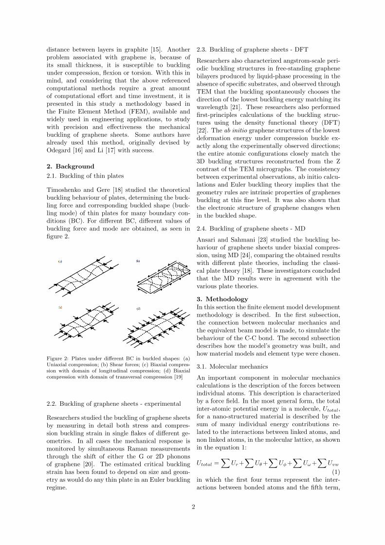
Timoshenko and Gere [18] studied the theoreticalbuckling behaviour of plates, determining the buck-ling force and corresponding buckled shape (buck-ling mode) of thin plates for many boundary con-ditions (BC). For different BC, different values ofbuckling force and mode are obtained, as seen infigure 2.
Figure 2: Plates under different BC in buckled shapes: (a)Uniaxial compression; (b) Shear forces; (c) Biaxial compres-sion with domain of longitudinal compression; (d) Biaxialcompression with domain of transversal compression [19]
2.2. Buckling of graphene sheets - experimental
Researchers studied the buckling of graphene sheetsby measuring in detail both stress and compres-sion buckling strain in single flakes of different ge-ometries. In all cases the mechanical response ismonitored by simultaneous Raman measurementsthrough the shift of either the G or 2D phononsof graphene [20]. The estimated critical bucklingstrain has been found to depend on size and geom-etry as would do any thin plate in an Euler bucklingregime.
2.3. Buckling of graphene sheets - DFT
Researchers also characterized angstrom-scale peri-odic buckling structures in free-standing graphenebilayers produced by liquid-phase processing in theabsence of specific substrates, and observed throughTEM that the buckling spontaneously chooses thedirection of the lowest buckling energy matching itswavelength [21]. These researchers also performedfirst-principles calculations of the buckling struc-tures using the density functional theory (DFT)[22]. The ab initio graphene structures of the lowestdeformation energy under compression buckle ex-actly along the experimentally observed directions;the entire atomic configurations closely match the3D buckling structures reconstructed from the Zcontrast of the TEM micrographs. The consistencybetween experimental observations, ab initio calcu-lations and Euler buckling theory implies that thegeometry rules are intrinsic properties of graphenesbuckling at this fine level. It was also shown thatthe electronic structure of graphene changes whenin the buckled shape.
2.4. Buckling of graphene sheets - MD
Ansari and Sahmani [23] studied the buckling be-haviour of graphene sheets under biaxial compres-sion, using MD [24], comparing the obtained resultswith different plate theories, including the classi-cal plate theory [18]. These investigators concludedthat the MD results were in agreement with thevarious plate theories.
3. MethodologyIn this section the finite element model developmentmethodology is described. In the first subsection,the connection between molecular mechanics andthe equivalent beam model is made, to simulate thebehaviour of the C-C bond. The second subsectiondescribes how the model’s geometry was built, andhow material models and element type were chosen.
3.1. Molecular mechanics
An important component in molecular mechanicscalculations is the description of the forces betweenindividual atoms. This description is characterizedby a force field. In the most general form, the totalinter-atomic potential energy in a molecule, Utotal,for a nano-structured material is described by thesum of many individual energy contributions re-lated to the interactions between linked atoms, andnon linked atoms, in the molecular lattice, as shownin the equation 1:
Utotal =∑
Ur+∑
Uθ+∑
Uφ+∑
Uω+∑
Uvw
(1)in which the first four terms represent the inter-actions between bonded atoms and the fifth term,
2

Uvw represents the van der Waals interaction be-tween any non bonded atoms, often described bythe Lennard-Jones potential [24], but here is de-spised due to its weak influence on the mechanicalproperties of graphene. The first four terms de-scribe the atoms motion and position lattice. Uris related to the axial deformation on the molecularlink, Uθ is the ’bending’ term and it describes angu-lar motion between three atoms and finally, Uφ andUω are the in-plane and out-of-plane torsion terms.These interactions are easily interpreted from a ba-sic molecule scheme depicted in figure 3:
Figure 3: Existing molecular interactions [25]
Obtaining accurate parameters for a force fieldamounts to fitting a set of experimental or empiricaldata to the assumed functional form, specifically,the force constants and equilibrium structure of themolecule. In this article the interatomic potentialused is AMBER [26]. It may be represented in itsharmonized form in equation 2:
Ur =1
2kr(δr)
2 , (2a)
Uθ =1
2kθ(δθ)
2 , (2b)
Uτ = Uφ + Uω =1
2kτ (δφ)2 . (2c)
where kr is the bond stretching force constant, kθis the bond bending force constant and kτ is theequivalent bond torsion term, and δr, δθ and δφ arethe bond stretching increment, bond angle variationand angle variation of bond twisting, respectively.
In order to determine the elastic moduli of thebeam elements that will compose graphene’s struc-ture, relations between the sectional stiffness pa-rameters in structural mechanics and the force-fieldconstants in molecular mechanics need to be ob-tained. For simplicity reasons, the sections of thebonds are assumed to be identical and circular.The elastic properties that need to be obtained areYoungs modulus E, Poisson’s ratio ν and the shear
modulus G. The deformation of a space-frame re-sults in changes of strain energies. Thus, the elas-tic moduli can be determined through the equiva-lence of the energies due to the interatomic interac-tions presented in equation 2 and the elastic energythat results from the deformation of the space-framestructural elements. As each of the energy terms ofequations 2 represents deformations in specific de-grees of freedom, the strain energies of structural el-ements under the same deformations in equivalentdegrees of freedom will be considered. Accordingto the Euler-Bernoulli beam model from classicalstructural mechanics, the strain energy UA of a uni-form beam of length L and cross-section A underpure axial force N is:
UA =1
2
∫ L
0
N2
EAdx =
1
2
EA
L(δL)2 (3)
The strain energy UM of a uniform beam with amoment of inertia I, under pure bending momentM is:
UM =1
2
∫ L
0
M2
EIdx =
1
2
EI
L(2α)2 . (4)
where α denotes the rotational angle at the ends ofthe beam. The strain energy UT of a uniform beamunder pure torsion T is:
UT =1
2
∫ L
0
T 2
GJdx =
1
2
GJ
L(δβ)2 . (5)
where δβ is the relative rotation between the endsof the beam and J the polar moment of inertia.
The equivalence of bond stretch equation 2a andaxial beam equation 3, bond and beam bendingequations 2b, 4 and bond and beam torsion equa-tions 2c, 5 serves as foundation of the equivalentatomic-beam model that is used in the analysisof graphene’s linear mechanical behaviour. Thisequivalence is presented in a more compact formin the following equations:
EA
L= kr,
EI
L= kθ,
GJ
L= kτ . (6)
The system of equations 6 establishes the founda-tion for the application of the theory of structuralmechanics in modelling of graphene or other simi-lar fullerene structures, for linear elastic simulation.The length of the C-C bond used was L = 0.142nm,based on the length of the covalent bond of carbonin a benzene ring [15].
3.2. Reference model
A finite element model was built in the FEM soft-ware ANSYS APDL R©. First, the hexagonal ge-ometry of graphene, shown in figure 4 was gener-ated through Matlab scripts. This script was built
3

to determine the coordinates of the carbon atoms,and which atoms are connected with each other,and writes the APDL code with the necessary com-mands to build a graphene column of any height.Then, using ANSYS R©, this column may be copiedand replicated to build a graphene sheet of anylength. This method allowed to build graphenesheets of many different sizes.
Figure 4: Example of a graphene sheet built using ANSYS R©
Regarding the properties of the beams that rep-resent the C-C bonds, they were determined usingthe AMBER force field, and the element sectionwas taken as circular, as noted in the previous sec-tion. Applying the force field in the equations 6,the properties of the beams were obtained and areexpressed in table 1.
Table 1: Force field constants k derived from AMBER inter-atomic potential and the results from equation 6 for E, Gand section diamater
Interatomic force fields
Data AMBER
kr[nNnm
]6.52 × 10⁻⁷
kθ[nN ·nmrad2
]8.76 × 10⁻¹⁰
kτ[nN ·nmrad2
]2.78 × 10⁻¹⁰
Beam characteristics
E [GPa] 5488G [GPa] 870.7d [nm] 0.147
To determine which beam element is more ap-propriate to test the stability of graphene sheets,two types of beam elements were used: BEAM4,that represents an Euler-Bernoulli beam, andBEAM188, representing a Timoshenko beam. Toverify the model, two types of tests were conducted:uniaxial traction tests to obtain the Young modu-lus E of the graphene sheets, and buckling tests
under four diferent BC’s to determine the buck-ling tension regarding the aspect ratio of the sheet.To find the Young modulus and the buckling ten-sion, it is necessary to consider a thickness t for thegraphene sheet. Two values of thickness were con-sidered: t = 0.34nm, most accepted in the scientificcommunity, and t = 0.147nm, that correspond tothe model thickness, given by the diameter of thebeams.
3.3. Verification
This section discusses the tests made in order todetermine which beam element type and thicknessshould be used in order to model the graphene sheetwith the best results.
3.3.1 Young modulus
As discussed previously in section 3, in order todetermine the Young modulus of a single sheet ofgraphene, two uniaxial traction test were made, onein the X direction, and other in the Y direction.
Figure 5: Deformed geometry for the zig-zag uniaxial test
Figure 6: Deformed geometry for the armchair uniaxial test
In these uniaxial tests, a force of 1nN was ap-plied to the nodes of one end of the sheet, while
4

restraining the movement of the other edge, result-ing on the deformed structures seen in figures 5 and6. For the uniaxial tests under the X direction:
Ex =σxεx
, εx =∆a
a, σx =
∑Fx
Asection(7)
where Ex is the Young moduli for the direction ofthe test, σx is the normal stress, εx is the strain,∆a is the displacement occurred determined withANSYS, a is the size of the sheet’s edge (Figure4), Fx the nodal force applied and A is the sectionarea of the sheet, in this case given by (a× t). Theprocess to determine Ey is similar.
Using the equations 7, it is possible to determinethe Young modulus of the sheet. In table 2, are theobtained results for both beam elements consider-ing both sheet thickness discussed in the previoussection, comparing them with results obtained fromvarious studies (MD, DFT, FEM, Monte Carlo) pre-sented in the literature.
The observation of the results presented in table2 shows that graphene has a slightly orthotropic be-haviour, as the Young’s moduli in the armchair andzig-zag directions is not equal, but as the differencebeing so narrow (2% - 4%) graphene can be easilyaccounted as an isotropic material. The models us-ing BEAM4 with t = 0.34nm and BEAM188 witht = 0.147nm resulted in a graphene sheet with aYoung modulus of around 1TPa, which is in agree-ment with other investigations, and that shows thatthese two models are fit to model graphene sheetsunder axial deformations. Also in the table arepresented the results from the present work andthe ones found in the literature, in order to verifythe methodology applied in this study. The liter-ature results come from similar methods that usethe finite element method, from MD simulations,and from DFT and other statistical physics simu-lations like the Monte Carlo method [33]. The re-sults from MD and DFT theory are more accuratethan the present ones, in principle due to the in-clusion of quantic, thermodynamic and many otherparameters involved in the atomic scale. Some ex-perimental studies are also presented, even if theydon’t provide the full spectrum of elastic properties,their results are the most accepted in the scientificcommunity (mainly the results from Lee [2]). Fi-nally, we can observe that the results from the fi-nite element method have a greater variability duethe different modeling procedures: Alzebdeh [28]used an equivalent continuum framework after us-ing the atomistic-beam model and Reddy [30] mini-mized the potential energy of the beams to find theequilibrium structure of graphene and its stifness.The simple fact of considering one or another typeof beam element has changed the properties deter-mined for the graphene sheet, and that is proof of
how important the modelling process is. This way,the two models that proved to model correctly thegraphene sheet will now be subjected to a bucklinganalysis.
3.3.2 Buckling tension
The two models that passed the axial deformationtest, were then subjected to a buckling analysis un-der four different BC’s:
• SET 1 - Two parallel edges simply supportedand uniaxial compression perpendicular to thesupported edges;
• SET 2 - Two parallel edges clamped and uniax-ial compression perpendicular to the clampededges;
• SET 3 - All edges supported and uniaxial com-pression;
• SET 4 - All edges simply supported and biaxialcompression.
These BC’s were applied to graphene sheets ofmultiple sizes, in order to evaluate the change ofthe buckling force with the aspect ratio (AR) b
a (aand b defined in figure 4). The results are shown infigures 7, 8, 9 and 10.
The results show that both models producesatisfactory results, with the model built withBEAM188 and thickness t = 0.147nm showing thebest agreement with the results obtained by Tser-pes [37], that tested two models built with FEM,using the continuum and the atomic-continumm ap-proach, and got results in agreement with classicplate theory [18]. This classical plate behaviour ofgraphene was observed using other methods, likeDFT [21] and MD [23], which indicate that thismodel is a good FEM model to study the stabil-ity of graphene sheets. The model using BEAM4and thickness t = 0.34nm showed some deviationswithin the obtained results, mainly in set 3, whichallows the conclusion that this type of beam ele-ment is not very good with out-of-plane deforma-tions, even though it was the the model that pro-duced the best result for in-plane deformation ofgraphene.
4. Parametric study on buckling of graphenesheets
Now that the model is built appropriately, with theright beam element, some other buckling tests us-ing different BC’s were made to observe the be-haviour of the graphene sheet under buckling. Inthis section will be presented 4 cases of grand to-tal of 32 tests. The results shown in this sectionwill be the variation of buckling force with respectto the geometric parameter b, set in figure 4, and
5

Table 2: Results obtained in this study, with other results obtained by other researchers using different methods
Researchers Earmchair [TPa] Ezigzag [TPa] E [TPa]
(FEM)
Presente (BEAM4/t = 0.34nm) 1.035 1.047 -Presente (BEAM4/t = 0.147nm) 2.394 2.423 -Presente (BEAM188/t = 0.34nm) 0.369 0.353 -Presente (BEAM188/t = 0.147nm) 0.854 0.818 -
Pedrosa [27] 0.749 0.763 -Alzebdeh [28] 0.990 0.100 -Scarpa [29] 1.957 1.379 -Reddy [30] 0.670 0.814 -Huang [31] - - 2.690
(MD)
Tsai [13] - - 0.912Ni [32] 1.050 1.130 -
(DFT e Monte Carlo)
Zakharchenko [33] - - 1.040Zhao [34] - - 0.910Liu [14] - - 1.050
(Experimental)
Lee [2] - - 1.010Frank [35] - - 1.000
Blakslee [36] - - 1.000
Figure 7: Variation of the buckling tension with respect tothe AR - Set 1
Figure 8: Variation of the buckling tension with respect tothe AR - Set 2
Figure 9: Variation of the buckling tension with respect tothe AR - Set 3
Figure 10: Variation of the buckling tension with respect tothe AR - Set 4
6

also the corresponding buckling mode. The casesunder study will be set 3 and 4, i.e., uniaxial andbiaxial compression with all edges supported, andalso two new ones, which will evaluate the effect ofshear stress, and bending, with all the edges sup-ported as well. All compressions presented here arein the Y direction and the following results wereobtained for a = 7.14nm, and then varying the sizeof b, in order to obtain AR’s from 0.3 to almost 5.The graphs give the buckling force variation to theparameter b for pinned and clamped supports, pre-senting also the associated buckling mode for bothsupports. The buckling modes shown were obtainedfor an AR=3 (b = 21.17nm).
Figure 11: Variation of the buckling tension with respect tothe AR for uniaxial compression - Pinned buckling mode onthe left and clamped buckling mode on the right
Figure 12: Variation of the buckling tension with respect tothe AR for biaxial compression - Pinned buckling mode onthe left and clamped buckling mode on the right
From the analysis of these figures, there are somejoint conclusions we can make about all of the cases:It can be seen that the clamped support alwaysresults in a higher buckling force, no matter theBC’s. It can also be observed that, when b � athere is no change in the buckling force, with this
Figure 13: Variation of the buckling tension with respect tothe AR for bending - Pinned buckling mode on the left andclamped buckling mode on the right
Figure 14: Variation of the buckling tension with respect tothe AR for shear forces - Pinned buckling mode on the leftand clamped buckling mode on the right
value remaining constant. The buckling mode doesnot show that behaviour, with the number of semi-waves becoming higher with the increasing size ofb, except for the biaxial case, which is a bit morecomplex. It is also noticeable that clamped edgesproduce more, but smaller semi-waves. When un-der biaxial compression, the buckling shape of thesheet will be either dominated by the longitudinalor the transversal compression. It can be seen infigure 12 that the change of the pinned support toa clamped one changes the domain of compressionfrom transversal to longitudinal. Now, looking atfigure 13, there are some interesting things happen-ing. Only the left side of the sheet is under com-pression in the Y direction, while the other half isunder traction, resulting in bending. Since only theleft side is under compression, the buckling defor-mation only appears on that side of the sheet, pro-ducing similar semi-waves to the uniaxial compres-sion test (figure 11), but only on half of the sheet.When on clamped edges, the buckling mode is a
7

bit different, with the semi-waves showing a curve.This happens because of the bending deformationof the sheet. Finally, analysing the case with shearforces (Figure 14), the buckling shape is again sim-ilar to the uniaxial compression test, but with thesemi-waves displaying in a diagonal direction dueto the shear forces. This case, together with thecase of bending, were the ones which produced thehighest values of buckling force, while the biaxialproduced the lowest. Sheets with other sizes of awere tested and different buckling forces were de-termined, which shows the importance of the ARin buckling of graphene sheets. It is of relevanceto show that the obtained buckling modes are inagreement with what was expected form the classicplate theory (Figure 2), which is another proof ofthe validity of this FEM model.
5. ConclusionsThis article was a extended resume of the thesisthat was set out to infer the buckling behaviour ofgraphene sheets with the development of a consis-tent FEM model. The methodology employed inthe present work was proved to be a simple, fastand accessible method to the engineering indus-try to study and analyse the mechanical propertiesof graphene, and other nano-materials, without arelevant loss of precision. This is needed due tographene many prospective applications in manyfields, which will require a deep understanding ofthe mechanical behaviour of graphene, so it can beused in the advanced technological components ofthe future.
The main findings of this thesis can be summa-rized in brief:
• The atomic-beam equivalent model in con-junction with the finite element method wereproven to be a useful methodology in the simu-lation of the mechanical behaviour of graphene[16], [17]. With low computational cost andprocessing, the results obtained for the me-chanical properties of this nano-material had asatisfactory precision, in comparison with theresults in the literature;
• BEAM188 (beam element following Timo-shenko beam theory) showed to be the bestbeam element to investigate out-of-plane defor-mations, when comparing with BEAM4 (beamelement following Euler-Bernoulli beam the-ory). Even so, when in axial deformation,BEAM4 obtained great results;
• Buckled graphene follows a classic plate be-haviour [18], something concluded by this in-vestigation and others too, not only by com-putational analysis [21], [23], but also throughexperimental trials [20];
• Graphene under biaxial compression may showdifferent buckling modes depending on the typeof support: When the support is pinned, thereis a domain of transversal compression, butwhen the support is clamped, the longitudinalcompression is the dominating one;
• Bending and shear forces produce the mosthigh buckling force values, whereas the biax-ial compression results in the lowest values ofbuckling force;
• Clamped supports always produce higher buck-ling forces;
• When all edges are supported, both the param-eters a and b have to be taken into account,since the AR plays a major role on the buck-ling force and mode;
• The buckling force assumes a constant valueafter b
a = 1. While b < a, the buckling force isvery sensitive to dimensions a and b.
• Different BC’s lead to different buckling forcesand modes. Since buckling may lead to struc-ture failure and has also been shown thatgraphene electronic properties change whenbuckled [21], the study of this phenomenon isof the utmost importance for graphene to beintroduced to nowadays devices.
After the development of this thesis, it is believedthat there are still many improvements to be donewithin the framework of the present work, as wellas other future developments. These include:
• Use the FEM model in multi-physics analysis,in order to simulate the variation of the me-chanical properties with temperature, or in thepresence of electrical currents through the ma-terial;
• Use different force fields, like the Morse inter-atomic potential, with non-linear characteris-tics;
• Create a nano-composite FEM model, whichuses the sheet modelled in the present workas a reinforcement element in a dispersion ofnano-platelets in a polymeric matrix, and con-duce studies on the mechanical behaviour ofsaid nano-composite.
• Study the behaviour of the graphene sheet inpost − buckling, i.e., what happens once thesheet assumes its buckled shape.
8

Acknowledgements
I would like to thank my supervisor, Professor NunoSilvestre, for giving me the opportunity to do inves-tigation in such a promising and interesting field, forall the technical support, and for the patience andguidance through all this process.
I would also like to thank Instituto Superior Tec-nico and the Department of Mechanical Engineer-ing, which provided everything I needed for my in-tellectual development and formation.
My gratefulness goes also to my family andfriends who helped me and guided me, supportingme every step of the way. It would’ve not beenpossible otherwise.
References
[1] K. S. Novoselov, A. K. Geim, S. V. Moro-zov, D. Jiang, Y. Zhang, S. V. Dubonos, I. V.Grigorieva, and A. A. Firsov. Electric field ef-fect in atomically thin carbon films. Science,306(5696):666–669, 2004.
[2] C. Lee and X. Wei. Measurement of the elasticproperties and intrinsic strenght of monolayergraphene. Science, 321(5887):385–388, 2008.
[3] F. V. Kusmartsev, W. M. Wu, M. P. Pierpoint,and K. C. Yung. Application of GrapheneWithin Optoelectronic Devices and Transis-tors, pages 191–221. Springer Singapore, Sin-gapore, 2015.
[4] J. Silvestre, N. Silvestre, and J. de Brito. Anoverview on the improvement of mechanicalproperties of ceramics nanocomposites. Jour-nal of Nanomaterials, 2015(106494), 2015.
[5] Nikhil Koratkar, M. Rafiee, and J. Rafiee. En-hanced mechanical properties of nanocompos-ites at low graphene content. ACS Nano,3(12):38843890, 2009.
[6] Luke S. Walker, Victoria R. Marotto, Moham-mad a. Rafiee, and Nikhil Koratkar. Tough-ening in graphene ceramic composites. ACSNano, 5(4):31823190, 2011.
[7] Jingyue Wang, Genlian Fan, and Zhixin Chen.Reinforcement with graphene nanosheets inaluminum matrix composites. Scripta mate-rialia, 66(8):594597, 2012.
[8] F. Schwierz. Graphene transistors. NatureNanotechnology, 5:487496, 2010.
[9] Seunghun Hong and Sung Myung. Nanotubeelectronics: A flexible approach to mobility.Nature Nanotechnology, 2:207 – 208, 2007.
[10] Wu Lu, S. Kannappana, K. Kaliyappanb, andR.K. Maniand. Graphene based supercapac-itors with improved specific capacitance andfast charging time at high current density.Technical report, Gwangju Institute of Scienceand Technology, South Korea, 2013.
[11] Qunwei Tang, Xiaopeng Wang, Peizhi Yang,and Benlin He. A solar cell that is triggeredby sun and rain. Angewandte Chemie Interna-tional Edition, 55(17):52435246, 2016.
[12] What is graphene? http://www.
graphene-uses.com/what-is-graphene/,2016. Acedido a: 13-09-2016.
[13] J. Tsai and J. Tu. Characterizing mechan-ical properties of graphite using moleculardynamics simulation. Materials and design,31(1):194199, 2009.
[14] Fang Liu, Pingbing Ming, and Ju Li. Ab initiocalculation of ideal strength and phonon insta-bility of graphene under tension. Physical Re-view B, 76(6):064120, 2007.
[15] O. A. Shenderova, V. Zhirnov, and D. W.Brenner. Carbon Nanostructures. Critical Re-views in Solid State and Materials Sciences,2006.
[16] Gregory M. Odegard and Thomas S. Gates.Equivalent-continuum modeling of nano-structured materials. Composites Science andTechnology, 62(14):18691880, 2002.
[17] Chunyu Li and Tsu Wei Chou. A structuralmechanics approach for the analysis of carbonnanotubes. International Journal of Solids andStructures, 40(10):24872499, 2003.
[18] Stephen Timoshenko and James Gere. Theoryof elastic stability. McGraw-Hill, 1963.
[19] Advanced structural steel design.http://fgg-web.fgg.uni-lj.si/~/pmoze/
esdep/master/wg06/l0300.htm, 2010. Ace-dido a: 30-09-2016.
[20] Otakar Frank, Georgia Tsoukleri, John Parthe-nios, Konstantinos Papagelis, Ibtsam Riaz,Rashid Jalil, Kostya S. Novoselov, and CostasGaliotis. Compression Behavior of Single-layerGraphene. ACS Nano, 4(6):31313138, 2010.
[21] Youdong Mao, Wei L Wang, Dongguang Wei,Efthimios Kaxiras, and Joseph G Sodroski.Graphene structures at an extreme degree ofbuckling. ACS Nano, 5(2):13951400, 2011.
9

[22] N. M. Harrison. An introduction to densityfunctional theory. NATO SCIENCE SERIESSUB SERIES III COMPUTER AND SYS-TEMS SCIENCES, 187:45–70, 2003.
[23] R. Ansari and S. Sahmani. Predic-tion of biaxial buckling behavior of single-layered graphene sheets based on nonlocalplate models and molecular dynamics simula-tions. Applied Mathematical Modelling, 37(12-13):73387351, 2013.
[24] N. Attig, K. Binder, H. Grubmller, and K. Kre-mer. Introduction to molecular dynamics simu-lation. Computational Soft Matter: From Syn-thetic Polymers to Proteins, 23:1–28, 2004.
[25] K. I. Tserpes and P. Papanikos. Finite elementmodeling of single-walled carbon nanotubes.Composites Part B: Engineering, 36(5):468477,2005.
[26] Wendy D. Cornell. A second generation forcefield for the simulation of proteins, nucleicacids, and organic molecules. Journal of theAmerican Chemical Society, 117(9):51795197,1995.
[27] Ricardo Pedrosa. Nanomateriais paraaplicacao aeroespacial: o estudo do grafeno.Master’s thesis, Instituto Superior Tecnico,Universidade de Lisboa, 2016.
[28] Khalid Alzebdeh. Evaluation of the in-plane effective elastic moduli of single-layeredgraphene sheet. International Journal of Me-chanics and Materials in Design, 8(3):269278,2012.
[29] Fabrizio Scarpa. The bending of single layergraphene sheets: the lattice versus continuumapproach. Nanotechnology, 21(12):125702–125711, 2010.
[30] C. D. Reddy, S. Rajendran, and K. M. Liew.Equilibrium configuration and continuum elas-tic properties of finite sized graphene. Nan-otechnology, 17(3):864–870, 2006.
[31] Y. Huang. Thickness of graphene and single-wall carbon nanotubes. Physical Review B- Condensed Matter and Materials Physics,74(24):245413, 2006.
[32] Zhongua Ni and Hao Bu. Anisotropic mechan-ical properties of graphene sheets from molec-ular dynamics. Physica B: Condensed Matter,405(5):13011306, 2009.
[33] K.V. Zakharchenko and M. I. Katsnelson. Fi-nite temperature lattice properties of graphene
beyond the quasiharmonic approximation.Physical Review Letters, 102(4):046808, 2009.
[34] H. Zhao, K. Min, and N.R Aluru. Size and chi-rality dependent elastic properties of graphenenanoribbons under uniaxial tension. Nano Let-ters, 9(8):30123015, 2009.
[35] Otakar Frank. Development of a universalstress sensor for graphene and carbon fibres.Nature communications, 2(255), 2011.
[36] O. L. Blakslee. Elastic constants of compres-sion annealed pyrolytic graphite. Journal ofApplied Physics, 41(8):3373–3382, 1970.
[37] K. I. Tserpes and I. Vatistas. Buckling analysisof pristine and defected graphene. MechanicsResearch Communications, 64:5056, 2015.
10


![Theelectronicproperties of bilayer graphene · graphene [40], twisted graphene [41–46] or two graphene sheets separated by a dielectric with, possibly, electronic interactions between](https://img.pdfslide.us/doc/110x75/5e69aa2b87c67d520529bd33/theelectronicproperties-of-bilayer-graphene-graphene-40-twisted-graphene-41a46.jpg)