Embed Size (px)
Citation preview

7/30/2019 BSC6900UMTS Hardware Description
http://slidepdf.com/reader/full/bsc6900umts-hardware-description 1/243
BSC6900 UMTS
V900R011C00
Hardware Description
Issue 10
Date 2012-06-30
HUAWEI TECHNOLOGIES CO., LTD.

7/30/2019 BSC6900UMTS Hardware Description
http://slidepdf.com/reader/full/bsc6900umts-hardware-description 2/243
Copyright © Huawei Technologies Co., Ltd. 2012. All rights reserved.
No part of this document may be reproduced or transmitted in any form or by any means without prior written
consent of Huawei Technologies Co., Ltd.
Trademarks and Permissions
and other Huawei trademarks are trademarks of Huawei Technologies Co., Ltd.
All other trademarks and trade names mentioned in this document are the property of their respective holders.
Notice
The purchased products, services and features are stipulated by the contract made between Huawei and the
customer. All or part of the products, services and features described in this document may not be within the
purchase scope or the usage scope. Unless otherwise specified in the contract, all statements, information,and recommendations in this document are provided "AS IS" without warranties, guarantees or representations
of any kind, either express or implied.
The information in this document is subject to change without notice. Every effort has been made in the
preparation of this document to ensure accuracy of the contents, but all statements, information, and
recommendations in this document do not constitute the warranty of any kind, express or implied.
Huawei Technologies Co., Ltd.
Address: Huawei Industrial Base
Bantian, Longgang
Shenzhen 518129
People's Republic of China
Website: http://www.huawei.com
Email: [email protected]
Issue 10 (2012-06-30) Huawei Proprietary and Confidential
Copyright © Huawei Technologies Co., Ltd.
i

7/30/2019 BSC6900UMTS Hardware Description
http://slidepdf.com/reader/full/bsc6900umts-hardware-description 3/243
About This Document
Overview
This document describes the hardware components of the BSC6900. It provides the users witha detailed and comprehensive reference to the BSC6900.
Product Version
The following table lists the product version related to this document.
Product Name Product Version
BSC6900 V900R011C00
Intended Audience
This document is intended for:
l Installers
l Site operators
Organization
1 Changes in the BSC6900 UMTS Hardware Description
This chapter describes the changes in the BSC6900 UMTS Hardware Description.
2 Physical Structure
The BSC6900 hardware consists of the cabinet, cables, GPS antenna system, and LMT.
3 Cabinet
The cabinet is the main component of the BSC6900 system. The BSC6900 uses the Huawei N68E-22 cabinet or the Huawei N68E-21-N cabinet.
BSC6900 UMTS
Hardware Description About This Document
Issue 10 (2012-06-30) Huawei Proprietary and Confidential
Copyright © Huawei Technologies Co., Ltd.
ii

7/30/2019 BSC6900UMTS Hardware Description
http://slidepdf.com/reader/full/bsc6900umts-hardware-description 4/243
4 Components of the Cabinet
Components of the cabinet involve the power distribution box, air defence subrack, rear cable
trough, subrack, independent fan subrack, rack.
5 Subracks
This chapter describes subracks. Subracks are used to house boards and backplanes to form an
independent unit.
6 Boards
This chapter describes the boards supported by the BSC6900.
7 Cables
This chapter describes all the cables used inside and outside the BSC6900 cabinet.
8 LEDs on the Boards
This chapter describes the LEDs on the BSC6900 boards.
9 DIP Switches on Components
This chapter describes the DIP switches on the boards and subracks of the BSC6900.
Conventions
Symbol Conventions
The symbols that may be found in this document are defined as follows.
Symbol Description
Indicates a hazard with a high level of risk, which if not
avoided, will result in death or serious injury.
Indicates a hazard with a medium or low level of risk, which
if not avoided, could result in minor or moderate injury.
Indicates a potentially hazardous situation, which if not
avoided, could result in equipment damage, data loss,
performance degradation, or unexpected results.
Indicates a tip that may help you solve a problem or save
time.
Provides additional information to emphasize or supplement
important points of the main text.
General Conventions
The general conventions that may be found in this document are defined as follows.
BSC6900 UMTS
Hardware Description About This Document
Issue 10 (2012-06-30) Huawei Proprietary and Confidential
Copyright © Huawei Technologies Co., Ltd.
iii

7/30/2019 BSC6900UMTS Hardware Description
http://slidepdf.com/reader/full/bsc6900umts-hardware-description 5/243
Convention Description
Times New Roman Normal paragraphs are in Times New Roman.
Boldface Names of files, directories, folders, and users are in
boldface. For example, log in as user root.
Italic Book titles are in italics.
Courier New Examples of information displayed on the screen are in
Courier New.
Command Conventions
The command conventions that may be found in this document are defined as follows.
Convention Description
Boldface The keywords of a command line are in boldface.
Italic Command arguments are in italics.
[ ] Items (keywords or arguments) in brackets [ ] are optional.
{ x | y | ... } Optional items are grouped in braces and separated by
vertical bars. One item is selected.
[ x | y | ... ] Optional items are grouped in brackets and separated by
vertical bars. One item is selected or no item is selected.
{ x | y | ... }* Optional items are grouped in braces and separated by
vertical bars. A minimum of one item or a maximum of all
items can be selected.
[ x | y | ... ]* Optional items are grouped in brackets and separated by
vertical bars. Several items or no item can be selected.
GUI Conventions
The GUI conventions that may be found in this document are defined as follows.
Convention Description
Boldface Buttons, menus, parameters, tabs, window, and dialog titles
are in boldface. For example, click OK .
> Multi-level menus are in boldface and separated by the ">"
signs. For example, choose File > Create > Folder.
Keyboard Operations
The keyboard operations that may be found in this document are defined as follows.
BSC6900 UMTS
Hardware Description About This Document
Issue 10 (2012-06-30) Huawei Proprietary and Confidential
Copyright © Huawei Technologies Co., Ltd.
iv

7/30/2019 BSC6900UMTS Hardware Description
http://slidepdf.com/reader/full/bsc6900umts-hardware-description 6/243
Format Description
Key Press the key. For example, press Enter and press Tab.
Key 1+Key 2 Press the keys concurrently. For example, pressing Ctrl+Alt
+A means the three keys should be pressed concurrently.
Key 1, Key 2 Press the keys in turn. For example, pressing Alt, A means
the two keys should be pressed in turn.
Mouse Operations
The mouse operations that may be found in this document are defined as follows.
Action Description
Click Select and release the primary mouse button without moving
the pointer.
Double-click Press the primary mouse button twice continuously and
quickly without moving the pointer.
Drag Press and hold the primary mouse button and move the
pointer to a certain position.
BSC6900 UMTS
Hardware Description About This Document
Issue 10 (2012-06-30) Huawei Proprietary and Confidential
Copyright © Huawei Technologies Co., Ltd.
v
7/30/2019 BSC6900UMTS Hardware Description
http://slidepdf.com/reader/full/bsc6900umts-hardware-description 7/243
Contents
About This Document.....................................................................................................................ii
1 Changes in the BSC6900 UMTS Hardware Description........................................................1
2 Physical Structure..........................................................................................................................8
3 Cabinet...........................................................................................................................................10
3.1 Appearance of the Cabinet...............................................................................................................................11
3.2 Classification of Cabinets.................................................................................................................................13
3.3 Components of the Cabinet..............................................................................................................................14
3.4 Technical Specifications of the Cabinet...........................................................................................................15
3.5 Cable Connections of the Cabinet....................................................................................................................17
3.5.1 Relation Between Power Outputs and Cabinet Components..................................................................17
3.5.2 Connections of Power Cables and PGND Cables in the Cabinet............................................................19
3.5.3 Distr ibution of Signal Cables for the MPR.............................................................................................23
3.5.4 Distribution of Signal Cables for the EPR...............................................................................................29
4 Components of the Cabinet.......................................................................................................35
4.1 Power Distribution Box....................................................................................................................................36
4.1.1 Front Panel of the Power Distribution Box.............................................................................................36
4.1.2 Rear Panel of the Power Distribution Box..............................................................................................37
4.1.3 Technical Specifications of the Power Distribution Box........................................................................38
4.1.4 Distr ibution of Power Switches on the Power Distribution Box.............................................................39
4.2 Air Defence Subrack........................................................................................................................................39
4.3 Rear Cable Trough............................................................................................................................................40
4.4 Independent Fan Subrack.................................................................................................................................40
4.4.1 Appearance of the Independent Fan Subrack..........................................................................................41
4.4.2 Technical Specifications of the Independent Fan Subrack......................................................................42
5 Subracks........................................................................................................................................43
5.1 Classification of Subracks................................................................................................................................44
5.2 Components of the Subrack..............................................................................................................................44
5.3 Fan Box.............................................................................................................................................................46
5.3.1 Fan Box (Configured with the PFCU Board)..........................................................................................46
5.3.2 Fan Box (Configured with the PFCB Board)..........................................................................................49
5.4 Slots in the Subrack..........................................................................................................................................51
BSC6900 UMTS
Hardware Description Contents
Issue 10 (2012-06-30) Huawei Proprietary and Confidential
Copyright © Huawei Technologies Co., Ltd.
vi

7/30/2019 BSC6900UMTS Hardware Description
http://slidepdf.com/reader/full/bsc6900umts-hardware-description 8/243
5.5 DIP Switch on the Subrack...............................................................................................................................52
5.6 Configuration of the Subrack...........................................................................................................................54
5.6.1 Configuration of the MPS........................................................................................................................54
5.6.2 Configuration of the EPS.........................................................................................................................55
5.7 Technical Specifications of the Subrack...........................................................................................................55
6 Boards............................................................................................................................................57
6.1 AEUa Board.....................................................................................................................................................62
6.1.1 Functions of the AEUa Board.................................................................................................................62
6.1.2 Panel of the AEUa Board........................................................................................................................62
6.1.3 LEDs on the AEUa Board.......................................................................................................................63
6.1.4 Ports on the AEUa Board........................................................................................................................64
6.1.5 DIP Switches on the AEUa Board...........................................................................................................64
6.1.6 Technical Specifications of the AEUa Board..........................................................................................67
6.2 AOUa Board.....................................................................................................................................................68
6.2.1 Functions of the AOUa Board.................................................................................................................69
6.2.2 Panel of the AOUa Board........................................................................................................................69
6.2.3 LEDs on the AOUa Board.......................................................................................................................70
6.2.4 Ports on the AOUa Board........................................................................................................................71
6.2.5 DIP Switches on the AOUa Board..........................................................................................................71
6.2.6 Technical Specifications of the AOUa Board.........................................................................................73
6.3 AOUc Board.....................................................................................................................................................75
6.3.1 Functions of the AOUc Board.................................................................................................................76
6.3.2 Panel of the AOUc Board........................................................................................................................76
6.3.3 LEDs on the AOUc Board.......................................................................................................................77
6.3.4 Ports on the AOUc Board........................................................................................................................78
6.3.5 Technical Specifications of the AOUc Board.........................................................................................79
6.4 DPUb Board.....................................................................................................................................................81
6.4.1 Functions of the DPUb Board.................................................................................................................82
6.4.2 Panel of the DPUb Board........................................................................................................................82
6.4.3 LEDs on the DPUb Board.......................................................................................................................83
6.4.4 Technical Specifications of the DPUb Board..........................................................................................84
6.5 DPUe Board......................................................................................................................................................856.5.1 Functions of the DPUe Board..................................................................................................................85
6.5.2 Panel of the DPUe Board.........................................................................................................................85
6.5.3 LEDs on the DPUe Board.......................................................................................................................86
6.5.4 Technical Specifications of the DPUe Board..........................................................................................87
6.6 FG2a Board.......................................................................................................................................................88
6.6.1 Functions of the FG2a Board...................................................................................................................88
6.6.2 Panel of the FG2a Board.........................................................................................................................88
6.6.3 LEDs on the FG2a Board........................................................................................................................89
6.6.4 Ports on the FG2a Board.........................................................................................................................90
6.6.5 Technical Specifications of the FG2a Board...........................................................................................91
BSC6900 UMTS
Hardware Description Contents
Issue 10 (2012-06-30) Huawei Proprietary and Confidential
Copyright © Huawei Technologies Co., Ltd.
vii

7/30/2019 BSC6900UMTS Hardware Description
http://slidepdf.com/reader/full/bsc6900umts-hardware-description 9/243
6.7 FG2c Board.......................................................................................................................................................92
6.7.1 Functions of the FG2c Board...................................................................................................................92
6.7.2 Panel of the FG2c Board.........................................................................................................................93
6.7.3 LEDs on the FG2c Board........................................................................................................................94
6.7.4 Ports on the FG2c Board.........................................................................................................................95
6.7.5 Technical Specifications of the FG2c Board...........................................................................................95
6.8 GCUa/GCGa Board..........................................................................................................................................97
6.8.1 Functions of the GCUa/GCGa Board......................................................................................................97
6.8.2 Panel of the GCUa/GCGa Board.............................................................................................................97
6.8.3 LEDs on the GCUa/GCGa Board............................................................................................................98
6.8.4 Ports on the GCUa/GCGa Board.............................................................................................................99
6.8.5 Technical Specifications of the GCUa/GCGa Board............................................................................100
6.9 GOUa Board...................................................................................................................................................100
6.9.1 Functions of the GOUa Board...............................................................................................................100
6.9.2 Panel of the GOUa Board......................................................................................................................101
6.9.3 LEDs on the GOUa Board.....................................................................................................................101
6.9.4 Ports on the GOUa Board......................................................................................................................102
6.9.5 Technical Specifications of the GOUa Board.......................................................................................102
6.10 GOUc Board.................................................................................................................................................105
6.10.1 Functions of the GOUc Board.............................................................................................................105
6.10.2 Panel of the GOUc Board....................................................................................................................105
6.10.3 LEDs on the GOUc Board...................................................................................................................106
6.10.4 Por ts on the GOUc Board....................................................................................................................1076.10.5 Technical Specifications of the GOUc Board.....................................................................................107
6.11 OMUa Boar d................................................................................................................................................110
6.11.1 Functions of the OMUa Board............................................................................................................110
6.11.2 Panel of the OMUa Board...................................................................................................................110
6.11.3 LEDs on the OMUa Board..................................................................................................................112
6.11.4 Por ts on the OMUa Board...................................................................................................................113
6.11.5 Technical Specifications of the OMUa Board.....................................................................................113
6.12 PAMU Boar d................................................................................................................................................115
6.12.1 Functions of the PAMU Board............................................................................................................115
6.12.2 Panel of the PAMU Board...................................................................................................................115
6.12.3 LEDs on the PAMU Board..................................................................................................................116
6.12.4 DIP Switch on the PAMU Board........................................................................................................116
6.12.5 Technical Specifications of the PAMU Board....................................................................................117
6.13 PEUa Board..................................................................................................................................................117
6.13.1 Functions of the PEUa Board..............................................................................................................118
6.13.2 Panel of the PEUa Board.....................................................................................................................118
6.13.3 LEDs on the PEUa Board....................................................................................................................119
6.13.4 Por ts on the PEUa Board.....................................................................................................................119
6.13.5 DIP Switches on the PEUa Board.......................................................................................................120
BSC6900 UMTS
Hardware Description Contents
Issue 10 (2012-06-30) Huawei Proprietary and Confidential
Copyright © Huawei Technologies Co., Ltd.
viii

7/30/2019 BSC6900UMTS Hardware Description
http://slidepdf.com/reader/full/bsc6900umts-hardware-description 10/243
6.13.6 Technical Specifications of the PEUa Board.......................................................................................122
6.14 PFCU Board.................................................................................................................................................124
6.14.1 Functions of the PFCU Board.............................................................................................................124
6.14.2 DIP Switch on the PFCU Board..........................................................................................................124
6.14.3 Technical Specifications of the PFCU Board......................................................................................126
6.15 PFCB Board..................................................................................................................................................126
6.15.1 Functions of the PFCB Board..............................................................................................................126
6.15.2 Pins on the PFCB Board......................................................................................................................126
6.15.3 Technical Specifications of the PFCU Board......................................................................................128
6.16 POUa Board..................................................................................................................................................128
6.16.1 Functions of the POUa Board..............................................................................................................128
6.16.2 Panel of the POUa Board.....................................................................................................................129
6.16.3 LEDs on the POUa Board...................................................................................................................129
6.16.4 Ports on the POUa Board.....................................................................................................................130
6.16.5 DIP Switches on the POUa Board.......................................................................................................131
6.16.6 Technical Specifications of the POUa Board......................................................................................132
6.17 POUc Board..................................................................................................................................................134
6.17.1 Functions of the POUc Board..............................................................................................................135
6.17.2 Panel of the POUc Board.....................................................................................................................135
6.17.3 LEDs on the POUc Board...................................................................................................................136
6.17.4 Ports on the POUc Board.....................................................................................................................137
6.17.5 Technical Specifications of the POUc Board......................................................................................138
6.18 SCUa Board..................................................................................................................................................1406.18.1 Functions of the SCUa Board..............................................................................................................140
6.18.2 Panel of the SCUa Board.....................................................................................................................140
6.18.3 LEDs on the SCUa Board....................................................................................................................141
6.18.4 Ports on the SCUa Board.....................................................................................................................142
6.18.5 Technical Specifications of the SCUa Board......................................................................................143
6.19 SPUa Board..................................................................................................................................................144
6.19.1 Functions of the SPUa Board..............................................................................................................144
6.19.2 Panel of the SPUa Board.....................................................................................................................145
6.19.3 LEDs on the SPUa Board....................................................................................................................146
6.19.4 Ports on the SPUa Board.....................................................................................................................147
6.19.5 Technical Specifications of the SPUa Board.......................................................................................147
6.20 SPUb Board..................................................................................................................................................148
6.20.1 Functions of the SPUb Board..............................................................................................................148
6.20.2 Panel of the SPUb Board.....................................................................................................................149
6.20.3 LEDs on the SPUb Board....................................................................................................................150
6.20.4 Ports on the SPUb Board.....................................................................................................................151
6.20.5 Technical Specifications of the SPUb Board......................................................................................151
6.21 UOIa Board...................................................................................................................................................152
6.21.1 Functions of the UOIa Board...............................................................................................................152
BSC6900 UMTS
Hardware Description Contents
Issue 10 (2012-06-30) Huawei Proprietary and Confidential
Copyright © Huawei Technologies Co., Ltd.
ix

7/30/2019 BSC6900UMTS Hardware Description
http://slidepdf.com/reader/full/bsc6900umts-hardware-description 11/243
6.21.2 Panel of the UOIa Board.....................................................................................................................153
6.21.3 LEDs on the UOIa Board....................................................................................................................153
6.21.4 Ports on the UOIa Board.....................................................................................................................154
6.21.5 Technical Specifications of the UOIa Board.......................................................................................154
6.22 UOIc Board...................................................................................................................................................157
6.22.1 Functions of the UOIc Board...............................................................................................................157
6.22.2 Panel of the UOIc Board.....................................................................................................................157
6.22.3 LEDs on the UOIc Board....................................................................................................................158
6.22.4 Por ts on the UOIc Board.....................................................................................................................159
6.22.5 Technical Specifications of the UOIc Board.......................................................................................159
7 Cables...........................................................................................................................................163
7.1 Power Ca bles..................................................................................................................................................165
7.2 PGND Ca bles.......................................................................... .......................................................................168
7.3 Optical Ca ble..................................................................................................................................................170
7.4 Optical Splitter/Combiner...............................................................................................................................171
7.5 75-ohm Coaxial Cable....................................................................................................................................174
7.6 Active/Standby 75-ohm Coaxial Cable..........................................................................................................176
7.7 120-ohm Twisted Pair Cable..........................................................................................................................179
7.8 Active/Standby 120-ohm Twisted Pair Cable................................................................................................181
7.9 BITS Clock Cable...........................................................................................................................................184
7.10 Y-Shaped Clock Cable.................................................................................................................................186
7.11 Line Clock Signal Cable...............................................................................................................................188
7.12 Straight-Through Cable................................................................................................................................1887.13 Monitoring Signal Cable for the Independent Fan Subrack.........................................................................191
7.14 Alarm Box Signal Cable...............................................................................................................................192
7.15 Monitoring Signal Cable for the Power Distribution Box............................................................................193
7.16 GPS Signal Transmission Cable...................................................................................................................195
7.17 OMU ser ial port cable..................................................................................................................................196
7.18 EMU RS485 Communication Cable............................................................................................................196
8 LEDs on the Boards...................................................................................................................198
8.1 LEDs on the AEUa Board..............................................................................................................................200
8.2 LEDs on the AOUa Board..............................................................................................................................2008.3 LEDs on the AOUc Board..............................................................................................................................201
8.4 LEDs on the DPUb Board..............................................................................................................................201
8.5 LEDs on the DPUe Board..............................................................................................................................202
8.6 LEDs on the FG2a Board...............................................................................................................................203
8.7 LEDs on the FG2c Board...............................................................................................................................203
8.8 LEDs on the GCUa/GCGa Board...................................................................................................................204
8.9 LEDs on the GOUa Board..............................................................................................................................205
8.10 LEDs on the GOUc Board............................................................................................................................205
8.11 LEDs on the OMUa Board...........................................................................................................................206
8.12 LEDs on the PAMU Board...........................................................................................................................207
BSC6900 UMTS
Hardware Description Contents
Issue 10 (2012-06-30) Huawei Proprietary and Confidential
Copyright © Huawei Technologies Co., Ltd.
x

7/30/2019 BSC6900UMTS Hardware Description
http://slidepdf.com/reader/full/bsc6900umts-hardware-description 12/243
8.13 LEDs on the PEUa Board.............................................................................................................................208
8.14 LEDs on the POUa Board............................................................................................................................208
8.15 LEDs on the POUc Board............................................................................................................................209
8.16 LEDs on the SCUa Board.............................................................................................................................209
8.17 LEDs on the SPUa Board.............................................................................................................................210
8.18 LEDs on the SPUb Board.............................................................................................................................211
8.19 LEDs on the UOIa Board.............................................................................................................................212
8.20 LEDs on the UOIc Board.............................................................................................................................212
9 DIP Switches on Components................................................................................................ 214
9.1 DIP Switch on the Subrack.............................................................................................................................215
9.2 DIP Switches on the AEUa Board..................................................................................................................217
9.3 DIP Switches on the AOUa Board.................................................................................................................220
9.4 DIP Switch on the PAMU Board...................................................................................................................222
9.5 DIP Switches on the PEUa Board..................................................................................................................223
9.6 DIP Switch on the PFCU Board.....................................................................................................................226
9.7 Pins on the PFCB Board.................................................................................................................................228
9.8 DIP Switches on the POUa Board..................................................................................................................229
BSC6900 UMTS
Hardware Description Contents
Issue 10 (2012-06-30) Huawei Proprietary and Confidential
Copyright © Huawei Technologies Co., Ltd.
xi
7/30/2019 BSC6900UMTS Hardware Description
http://slidepdf.com/reader/full/bsc6900umts-hardware-description 13/243
1 Changes in the BSC6900 UMTS Hardware
Description
This chapter describes the changes in the BSC6900 UMTS Hardware Description.
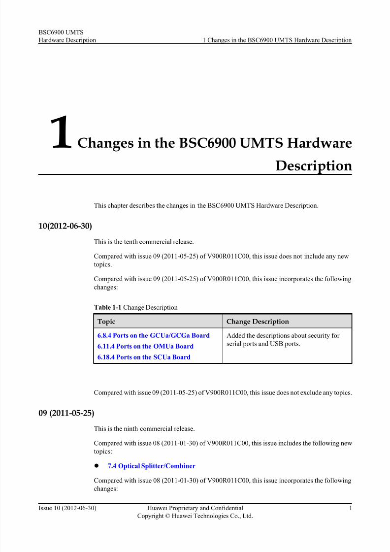
10(2012-06-30)
This is the tenth commercial release.
Compared with issue 09 (2011-05-25) of V900R011C00, this issue does not include any new
topics.
Compared with issue 09 (2011-05-25) of V900R011C00, this issue incorporates the following
changes:
Table 1-1 Change Description
Topic Change Description
6.8.4 Ports on the GCUa/GCGa Board
6.11.4 Ports on the OMUa Board
6.18.4 Ports on the SCUa Board
Added the descriptions about security for
serial ports and USB ports.
Compared with issue 09 (2011-05-25) of V900R011C00, this issue does not exclude any topics.
09 (2011-05-25)
This is the ninth commercial release.
Compared with issue 08 (2011-01-30) of V900R011C00, this issue includes the following new
topics:
l 7.4 Optical Splitter/Combiner
Compared with issue 08 (2011-01-30) of V900R011C00, this issue incorporates the followingchanges:
BSC6900 UMTS
Hardware Description 1 Changes in the BSC6900 UMTS Hardware Description
Issue 10 (2012-06-30) Huawei Proprietary and Confidential
Copyright © Huawei Technologies Co., Ltd.
1

7/30/2019 BSC6900UMTS Hardware Description
http://slidepdf.com/reader/full/bsc6900umts-hardware-description 14/243
Topic Change Description
6.4.3 LEDs on the DPUb Board
6.5.3 LEDs on the DPUe Board
Modified the meaning of the ACT indicator.
6.19.5 Technical Specifications
of the SPUa Board
6.20.5 Technical Specifications
of the SPUb Board
Modified technical specifications of boards.
6 Boards Supplemented the number of UDP ports or CIDs for the
following interface boards: AEUa, AOUa, UOIa, PEUa,
POUa, GOUa, FG2a, AOUc, UOIc, POUc, GOUc, and
FG2c.
6 Boards Supplemented the prerequisites for the specifications of
the following boards: AEUa, AOUa, AOUc, DPUb,
DPUe, FG2a, FG2c, GOUa, GOUc, PEUa, POUa, POUc,
UOIa, and UOIc.
6 Boards Supplemented the number of connections for the
following boards: AEUa, AOUa, AOUc, FG2a, FG2c,
GOUa, GOUc, PEUa, POUa, POUc, UOIa, and UOIc.
6 Boards Supplemented the specifications of UDP ports or CIDs
for interface boards.
Compared with issue 08 (2011-01-30) of V900R011C00, this issue does not exclude any topics.
08 (2011-01-30)
This is the eighth commercial release.
Compared with issue 07 (2010-09-15) of V900R011C00, this issue does not include any new
topics.
Compared with issue 07 (2010-09-15) of V900R011C00, this issue incorporates the following
changes:
Topic Change Description
4.1.2 Rear Panel of the Power
Distribution Box
Modified the figure of the rear panel of the high-power
power distribution box.
7.18 EMU RS485
Communication Cable
Modified the installation of EMU RS485 communication
cable.
Compared with issue 07 (2010-09-15) of V900R011C00, this issue does not exclude any topics.
BSC6900 UMTS
Hardware Description 1 Changes in the BSC6900 UMTS Hardware Description
Issue 10 (2012-06-30) Huawei Proprietary and Confidential
Copyright © Huawei Technologies Co., Ltd.
2

7/30/2019 BSC6900UMTS Hardware Description
http://slidepdf.com/reader/full/bsc6900umts-hardware-description 15/243
07 (2010-09-15)
This is the seventh commercial release.
Compared with issue 06 (2010-05-31) of V900R011C00, this issue does not include any new
topics.
Compared with issue 06 (2010-05-31) of V900R011C00, this issue incorporates the following
changes:
Topic Change Description
6.19.5 Technical Specifications
of the SPUa Board
Modified the information about the processing capability
of the main control SPUa board and the non-main control
SPUa board.
Compared with issue 06 (2010-05-31) of V900R011C00, this issue does not exclude any topics.
06 (2010-05-31)
This is the sixth commercial release.
Compared with issue 05 (2010-03-25) of V900R011C00, this issue includes the following new
topics:
l 7.17 OMU serial port cable
Compared with issue 05 (2010-03-25) of V900R011C00, this issue incorporates the followingchanges:
Topic Change Description
6.4 DPUb Board Modified the description about the slots for the DPUb
board.
6.5 DPUe Board Modified the description about the slots for the DPUe
board.
6.18.4 Ports on the SCUa Board Modified the description about the ports on SCUa board.
Compared with issue 05 (2010-03-25) of V900R011C00, this issue does not exclude any topics.
05 (2010-03-25)
This is the fifth commercial release.
Compared with issue 04 (2010-01-30) of V900R011C00, this issue does not include any new
topics.
Compared with issue 04 (2010-01-30) of V900R011C00, this issue incorporates the followingchanges:
BSC6900 UMTS
Hardware Description 1 Changes in the BSC6900 UMTS Hardware Description
Issue 10 (2012-06-30) Huawei Proprietary and Confidential
Copyright © Huawei Technologies Co., Ltd.
3

7/30/2019 BSC6900UMTS Hardware Description
http://slidepdf.com/reader/full/bsc6900umts-hardware-description 16/243
Topic Change Description
DIP Switch on the Subrack Optimized the figure of the setting of the DIP
Switch.
7.18 EMU RS485 Communication Cable Optimized the figure of the EMU RS485communication cable.
Compared with issue 04 (2010-01-30) of V900R 011C00, this issue does not exclude any topics.
04 (2010-01-30)
This is the fourth commercial release.
Compared with issue 03 (2009-12-05) of V900R011C00, this issue does not include any newtopics.
Compared with issue 03 (2009-12-05) of V900R011C00, this issue incorporates the following
changes:
Topic Change Description
6 Boards Modified the description about the logical
function of the DPUb board.
Compared with issue 03 (2009-12-05) of V900R011C00, this issue does not exclude any topics.
03 (2009-12-05)
This is the third commercial release.
Compared with issue 02 (2009-10-30) of V900R011C00, this issue includes the following new
topics:
l Relation Between Power Outputs and Cabinet Components
Compared with issue 02 (2009-10-30) of V900R011C00, this issue incorporates the following
changes:
Topic Change Description
6.3.2 Panel of the AOUc Board,6.7.2 Panel
of the FG2c Board,6.10.2 Panel of the
GOUc Board,6.17.2 Panel of the POUc
Board,6.22.2 Panel of the UOIc Board
Modified the figures of the panel of the AOUc
board, FG2c board, GOUc board, POUc
board, and UOIc board.
6.3.4 Ports on the AOUc Board,6.7.4 Ports
on the FG2c Board,6.10.4 Ports on the
GOUc Board,6.17.4 Ports on the POUc
Board,6.22.4 Ports on the UOIc Board
Deleted the description about the 2M0 and
2M1 ports of the AOUc board, FG2c board,
GOUc board, POUc board, and UOIc board.
BSC6900 UMTS
Hardware Description 1 Changes in the BSC6900 UMTS Hardware Description
Issue 10 (2012-06-30) Huawei Proprietary and Confidential
Copyright © Huawei Technologies Co., Ltd.
4

7/30/2019 BSC6900UMTS Hardware Description
http://slidepdf.com/reader/full/bsc6900umts-hardware-description 17/243
Topic Change Description
DIP Switch on the Subrack Modified the description about bit 8 of the
DIP switch on the subrack.
6.1.5 DIP Switches on the AEUa Board,6.13.5 DIP Switches on the PEUa Board
Optimized the description about DIPSwitches on the AEUa board and PEUa
board.
6.2.2 Panel of the AOUa Board,6.6.2 Panel
of the FG2a Board,6.8.2 Panel of the
GCUa/GCGa Board,6.9.2 Panel of the
GOUa Board,6.11.2 Panel of the OMUa
Board,6.16.2 Panel of the POUa Board,
6.18.2 Panel of the SCUa Board,6.21.2
Panel of the UOIa Board,6.19.2 Panel of
the SPUa Board,6.20.2 Panel of the SPUb
Board
Optimized the figures of the panel of the
AOUa board, FG2a board, GCUa/GCGa
board, GOUa board, OMUa board, POUa
board, SCUa board, UOIa board, SPUa
board, and SPUb board.
DIP Switch on the Subrack Optimized the figure of the cover plate for the
DIP switch on the subrack.
6.3.5 Technical Specifications of the AOUc
Board,6.6.5 Technical Specifications of the
FG2a Board,6.9.5 Technical Specifications
of the GOUa Board,6.7.5 Technical
Specifications of the FG2c Board,6.10.5
Technical Specifications of the GOUc
Board,6.21.5 Technical Specifications of
the UOIa Board,6.22.5 TechnicalSpecifications of the UOIc Board,6.17.5
Technical Specifications of the POUc
Board
Optimized the description about technical
specifications of the AOUc board, FG2a
board, GOUa board, FG2c board, GOUc
board, UOIa board, UOIc board, and POUc
board.
3.1 Appearance of the Cabinet Modified the figure about the physical
appearance of the N68-21-N cabinet. In
addition, changed the cabinet model name
N68-21-N to N68E-21-N.
Compared with issue 02 (2009-10-30) of V900R011C00, this issue does not exclude any topics.
02 (2009-10-30)
This is the second commercial release.
Compared with issue 01 (2009-07-30) of V900R011C00, this issue includes the following new
topics:
l 2 Physical Structure
l 6.1.6 Technical Specifications of the AEUa Board
l 6.2.6 Technical Specifications of the AOUa Board
l 6.3.5 Technical Specifications of the AOUc Board
BSC6900 UMTS
Hardware Description 1 Changes in the BSC6900 UMTS Hardware Description
Issue 10 (2012-06-30) Huawei Proprietary and Confidential
Copyright © Huawei Technologies Co., Ltd.
5

7/30/2019 BSC6900UMTS Hardware Description
http://slidepdf.com/reader/full/bsc6900umts-hardware-description 18/243
l 6.4.4 Technical Specifications of the DPUb Board
l 6.5.4 Technical Specifications of the DPUe Board
l 6.6.5 Technical Specifications of the FG2a Board
l6.7.5 Technical Specifications of the FG2c Board
l 6.8.5 Technical Specifications of the GCUa/GCGa Board
l 6.9.5 Technical Specifications of the GOUa Board
l 6.10.5 Technical Specifications of the GOUc Board
l 6.11.5 Technical Specifications of the OMUa Board
l 6.12.5 Technical Specifications of the PAMU Board
l 6.13.6 Technical Specifications of the PEUa Board
l 6.14.3 Technical Specifications of the PFCU Board
l 6.15.3 Technical Specifications of the PFCU Board
l 6.16.6 Technical Specifications of the POUa Board
l 6.17.5 Technical Specifications of the POUc Board
l 6.18.5 Technical Specifications of the SCUa Board
l 6.19.5 Technical Specifications of the SPUa Board
l 6.20.5 Technical Specifications of the SPUb Board
l 6.21.5 Technical Specifications of the UOIa Board
l 6.22.5 Technical Specifications of the UOIc Board
Compared with issue 01 (2009-07-30) of V900R011C00, this issue incorporates the following
changes:
Topic Change Description
6.16.1 Functions of the POUa Board Added the description about the Automatic
Protection Switching (APS) function.
6.21.1 Functions of the UOIa Board Added the description about the APS
function.
6.9.1 Functions of the GOUa Board Added the description about the routing-
based backup and load sharing functions.
6.6.1 Functions of the FG2a Board Added the description about the link aggregation function at the MAC layer.
6.3.1 Functions of the AOUc Board Added the description about the support for
the Iur interface.
6.22.1 Functions of the UOIc Board Added the description about the support for
the Iur interface.
6.17.1 Functions of the POUc Board Added the description about the support for
the Iur interface.
6.7.1 Functions of the FG2c Board Added the description about the support for
the Iur interface.
BSC6900 UMTS
Hardware Description 1 Changes in the BSC6900 UMTS Hardware Description
Issue 10 (2012-06-30) Huawei Proprietary and Confidential
Copyright © Huawei Technologies Co., Ltd.
6

7/30/2019 BSC6900UMTS Hardware Description
http://slidepdf.com/reader/full/bsc6900umts-hardware-description 19/243
Topic Change Description
6.10.1 Functions of the GOUc Board Added the description about the APS function
and the description about the support for the
Iur interface.
6.19.1 Functions of the SPUa Board Optimized the description about the functions
of the MPU and CPUS subsystems.
6.20.1 Functions of the SPUb Board Optimized the description about the functions
of the MPU and CPUS subsystems.
Compared with issue 01 (2009-07-30) of V900R011C00, this issue does not exclude any topics.
01 (2009-07-30)This is the first commercial release.
BSC6900 UMTS
Hardware Description 1 Changes in the BSC6900 UMTS Hardware Description
Issue 10 (2012-06-30) Huawei Proprietary and Confidential
Copyright © Huawei Technologies Co., Ltd.
7

7/30/2019 BSC6900UMTS Hardware Description
http://slidepdf.com/reader/full/bsc6900umts-hardware-description 20/243
2 Physical Structure
The BSC6900 hardware consists of the cabinet, cables, GPS antenna system, and LMT.
Figure 2-1 shows the BSC6900 physical structure.
Figure 2-1 BSC6900 physical structure
(1) GPS: Global Positioning System (2) PDF: Power Distribution Frame (DC)
(3) LMT: Local Maintenance Terminal
Table 2-1 describes the components of the BSC6900.
BSC6900 UMTS
Hardware Description 2 Physical Structure
Issue 10 (2012-06-30) Huawei Proprietary and Confidential
Copyright © Huawei Technologies Co., Ltd.
8

7/30/2019 BSC6900UMTS Hardware Description
http://slidepdf.com/reader/full/bsc6900umts-hardware-description 21/243
Table 2-1 Components of the BSC6900
Component Description
Cabinet For details, see 3 Cabinet.
Cables For details, see 7 Cables.
GPS antenna system The GPS antenna system consists of the antenna, feeder, jumper,
and surge protector.
The GPS antenna system is used to receive GPS satellite signals. It
is optional.
LMT The LMT refers to the operation and maintenance (OM) terminal
that is installed with the Huawei Local Maintenance Terminal
software and is connected to the OM network of the BSC6900. The
LMT is used to operate and maintain the BSC6900.
For details, see the BSC6900 UMTS LMT User Guide.
BSC6900 UMTS
Hardware Description 2 Physical Structure
Issue 10 (2012-06-30) Huawei Proprietary and Confidential
Copyright © Huawei Technologies Co., Ltd.
9

7/30/2019 BSC6900UMTS Hardware Description
http://slidepdf.com/reader/full/bsc6900umts-hardware-description 22/243
3 Cabinet
About This Chapter
The cabinet is the main component of the BSC6900 system. The BSC6900 uses the Huawei
N68E-22 cabinet or the Huawei N68E-21-N cabinet.
3.1 Appearance of the Cabinet
The N68E-22 cabinet is of two types, namely, the single-door cabinet and the double-door
cabinet. The N68E-21-N cabinet is a double-door cabinet.
3.2 Classification of Cabinets
Based on functions, cabinets are classified into the main processing rack (MPR) and the extended
processing rack (EPR).
3.3 Components of the Cabinet
The components of the BSC6900 cabinet are the power distribution box, subrack, air defence
subrack, inde pendent fan subrack (configur ed in only the Huawei N68E-22 cabinet), cable rack,
rack, and rear cable trough.
3.4 Technical Specifications of the Cabinet
The technical specifications of the cabinet consist of cabinet dimensions, height of the available
space, cabinet weight, rated input voltage, input voltage range, and Electromagnetic
Compatibility (EMC).
3.5 Cable Connections of the Cabinet
This section describes the connections of the power cables, PGND cables, and signal cables in
the cabinet.
BSC6900 UMTS
Hardware Description 3 Cabinet
Issue 10 (2012-06-30) Huawei Proprietary and Confidential
Copyright © Huawei Technologies Co., Ltd.
10

7/30/2019 BSC6900UMTS Hardware Description
http://slidepdf.com/reader/full/bsc6900umts-hardware-description 23/243
3.1 Appearance of the Cabinet
The N68E-22 cabinet is of two types, namely, the single-door cabinet and the double-door
cabinet. The N68E-21-N cabinet is a double-door cabinet.
Figure 3-1 shows the single-door N68E-22 cabinet. Figure 3-2 shows the double-door N68E-22
cabinet.
Figure 3-3 shows the N68E-21-N cabinet.
Figure 3-1 Single-door N68E-22 cabinet
BSC6900 UMTS
Hardware Description 3 Cabinet
Issue 10 (2012-06-30) Huawei Proprietary and Confidential
Copyright © Huawei Technologies Co., Ltd.
11

7/30/2019 BSC6900UMTS Hardware Description
http://slidepdf.com/reader/full/bsc6900umts-hardware-description 24/243
Figure 3-2 Double-door N68E-22 cabinet
BSC6900 UMTS
Hardware Description 3 Cabinet
Issue 10 (2012-06-30) Huawei Proprietary and Confidential
Copyright © Huawei Technologies Co., Ltd.
12

7/30/2019 BSC6900UMTS Hardware Description
http://slidepdf.com/reader/full/bsc6900umts-hardware-description 25/243
Figure 3-3 N68E-21-N cabinet
3.2 Classification of Cabinets
Based on functions, cabinets are classified into the main processing rack (MPR) and the extended
processing rack (EPR).
MPR
Only one MPR is configured in the BSC6900.
EPR
The number of EPRs to be configured depends on the traffic volume, but only one EPR can be
configured in the BSC6900. You can also choose not to configure the EPR.
For details on the components of the MPR or the EPR, see 3.3 Components of the Cabinet.
BSC6900 UMTS
Hardware Description 3 Cabinet
Issue 10 (2012-06-30) Huawei Proprietary and Confidential
Copyright © Huawei Technologies Co., Ltd.
13

7/30/2019 BSC6900UMTS Hardware Description
http://slidepdf.com/reader/full/bsc6900umts-hardware-description 26/243
3.3 Components of the Cabinet
The components of the BSC6900 cabinet are the power distribution box, subrack, air defence
subrack, independent fan subrack (configured in only the Huawei N68E-22 cabinet), cable rack,
rack, and rear cable trough.
Figure 3-4 shows the components of the BSC6900 cabinet (N68E-22 model).
Figure 3-4 Components of the cabinet (N68E-22 model)
(1) Air inlet (2) Independent fan subrack (3) Subrack
(4) Air defence subrack (5) Filler panel (6) Power distribution box
(7) Cable rack (8) Rear cable trough
BSC6900 UMTS
Hardware Description 3 Cabinet
Issue 10 (2012-06-30) Huawei Proprietary and Confidential
Copyright © Huawei Technologies Co., Ltd.
14

7/30/2019 BSC6900UMTS Hardware Description
http://slidepdf.com/reader/full/bsc6900umts-hardware-description 27/243
Table 3-1 lists the components of the cabinet and describes their configurations.
Table 3-1 Configuration of the cabinet
Component Configuration
Power Distribution Box Only one power distribution box is
configured.
Subrack l The MPR is configured with one
main processing subrack (MPS) and
depending on the traffic volume zero
to two extended processing subracks
(EPSs).
l The EPR is configured with one to
three EPSs, depending on the traffic
volume.
Air Defence Subrack Two air defence subracks are
configured.
Independent Fan Subrack Only one independent fan subrack is
configured in the N68E-22 cabinet and
no independent fan subrack is
configured in the N68E-21-N cabinet.
Rear Cable Trough Three rear cable troughs are configured.
NOTE
l The subracks are numbered from bottom to top, and the MPS is numbered 0.
l The components of the N68E-21-N cabinet is the same as those of the N68E-22 cabinet, except that the
N68E-21-N cabinet is not configured with the independent fan subrack.
3.4 Technical Specifications of the Cabinet
The technical specifications of the cabinet consist of cabinet dimensions, height of the available
space, cabinet weight, rated input voltage, input voltage range, and Electromagnetic
Compatibility (EMC).
Technical Specifications of the BSC6900 Cabinet (N68E-22)
The BSC6900 uses the Huawei N68E-22 cabinet or N68E-21-N cabinet. The two models of
cabinets have different technical specifications.
Table 3-2 describes the technical specifications of the BSC6900 cabinet (N68E-22).
Table 3-2 Technical specifications of the BSC6900 cabinet (N68E-22)
Item Specification
Dimensions 2,200 mm (height) x 600 mm (width) x 800 mm (depth)
BSC6900 UMTS
Hardware Description 3 Cabinet
Issue 10 (2012-06-30) Huawei Proprietary and Confidential
Copyright © Huawei Technologies Co., Ltd.
15

7/30/2019 BSC6900UMTS Hardware Description
http://slidepdf.com/reader/full/bsc6900umts-hardware-description 28/243
Item Specification
Height of the available space 46 U (1 U = 44.45 mm = 1.75 inches)
Weight l Empty cabinet≤ 100 kg
l Cabinet in full configuration≤ 320 kg
Rated input voltage -48 V DC power supply
Input voltage range -40 V to -57 V
EMC l Meets the requirements in ETSI EN300 386
l Meets the requirements in Council directive 89/336/
EEC
Power consumption The cabinet power consumption equals the sum of power
consumption of all subracks in the cabinet.
It is recommended that the power distribution system provide a maximum of 5100 W power per cabinet to
facilitate capacity expansion.
Heat dissipation l MPR ≤ 4100 W
l EPR ≤ 4100 W
CAUTION
When the voltage of power supply is lower than the lower threshold of the input voltage scope,
multiple boards may become abnormal at the same time. Therefore, check the power system if
multiple boards are abnormal at the same time.
Technical Specifications of the BSC6900 Cabinet (N68E-21-N)
Table 3-3 describes the technical specifications of the BSC6900 cabinet (N68E-21-N).
Table 3-3 Technical specifications of the BSC6900 cabinet (N68E-21-N)
Item Specification
Dimensions 2,130 mm (height) x 600 mm (width) x 800 mm (depth)
Height of the available space 44 U (1 U = 44.45 mm = 1.75 inches)
Weight l Empty cabinet≤ 155 kg
l Cabinet in full configuration≤ 380 kg
Rated input voltage -48 V
Input voltage range -40 V to -57 V
BSC6900 UMTS
Hardware Description 3 Cabinet
Issue 10 (2012-06-30) Huawei Proprietary and Confidential
Copyright © Huawei Technologies Co., Ltd.
16
7/30/2019 BSC6900UMTS Hardware Description
http://slidepdf.com/reader/full/bsc6900umts-hardware-description 29/243
Item Specification
EMC l Meets the requirements in GR 1089
l Meets the requirements in ETSI EN300 386
l Meets the requirements in Council directive 89/336/EEC
NOTE
An empty cabinet refers to the one that is installed with front and back doors, side panels, a power
distribution box, and a set of cables.
CAUTION
When the voltage of power supply is lower than the lower threshold of the input voltage scope,
multiple boar ds may become abnormal at the same time. Therefore, check the power system if
multiple boards are abnormal at the same time.
3.5 Cable Connections of the Cabinet
This section describes the connections of the power cables, PGND cables, and signal cables in
the cabinet.
NOTE
The BSC6900 uses the Huawei N68E-22 or N68E-21-N cabinet. Only the Huawei N68E-22 cabinet requires
the independent fan subrack. The MPR and EPR mentioned in this section are of the N68E-22 model.
3.5.1 Relation Between Power Outputs and Cabinet Components
This section describes the fixed relation between the outputs of the PDF and the inputs of power
distribution box as well as between the outputs of power distribution box and the components
of the cabinet.
For details on the working mechanism of the power system, see the Power Supply Principle.
Figure 3-5 shows the working mechanism of the power distribution box in the MPR. Table3-4 describes the working mechanism of the power distribution box in the MPR.
BSC6900 UMTS
Hardware Description 3 Cabinet
Issue 10 (2012-06-30) Huawei Proprietary and Confidential
Copyright © Huawei Technologies Co., Ltd.
17

7/30/2019 BSC6900UMTS Hardware Description
http://slidepdf.com/reader/full/bsc6900umts-hardware-description 30/243
Figure 3-5 Working mechanism of the power distribution box in the MPR
Table 3-4 Working mechanism of the power distribution box in the MPR
PDF Output Input of PowerDistribution Box
Outputof PowerDistribution Box
Subrack Input
63 A -48 V DC
output 1
A1(-) A7 NEG
(-)
-48 V DC input 2 on the
independent fan subrack
A8 NEG(-)
-48 V DC input 2 on subrack 2
63 A -48 V DC
output 2
B1(-) B7 NEG(-) -48 V DC input 1 on the
independent fan subrack
B8 NEG(-) -48 V DC input 1 on subrack 2
63 A RTN power
output 1
A1(+) A7 RTN
(+)
RTN power input 2 on the
independent fan subrack
A8 RTN
(+)
RTN power input 2 on subrack
2
BSC6900 UMTS
Hardware Description 3 Cabinet
Issue 10 (2012-06-30) Huawei Proprietary and Confidential
Copyright © Huawei Technologies Co., Ltd.
18

7/30/2019 BSC6900UMTS Hardware Description
http://slidepdf.com/reader/full/bsc6900umts-hardware-description 31/243
PDF Output Input of PowerDistribution Box
Outputof PowerDistribution Box
Subrack Input
63 A RTN power
output 2
B1(+) B7 RTN
(+)
RTN power input 1 on the
independent fan subrack
B8 RTN
(+)
RTN power input 1 on subrack
2
100 A -48 V DC
output 1
A3(-) A9 NEG
(-)
-48 V DC input 2 on subrack 1
A10 NEG
(-)
-48 V DC input 2 on subrack 0
100 A -48 V DC
output 2
B3(-) B9 NEG(-) -48 V DC input 1 on subrack 1
B10 NEG
(-)
-48 V DC input 1 on subrack 0
100 A RTN power
output 1
A3(+) A9 RTN
(+)
RTN power input 2 on subrack
1
A10 RTN
(+)
RTN power input 2 on subrack
0
100 A RTN power
output 2
B3(+) B9 RTN
(+)
RTN power input 1 on subrack
1
B10 RTN(+)
RTN power input 1 on subrack 0
3.5.2 Connections of Power Cables and PGND Cables in the Cabinet
The power cables in the cabinet are used to connect the power distribution box to the subrack
and independent fan subrack, thus ensuring stable power supply to the subrack and independent
fan subrack. The PGND cables are used to connect the cabinet to the grounding bar in the
equipment room, thus protecting the cabinet from electrostatic discharge.
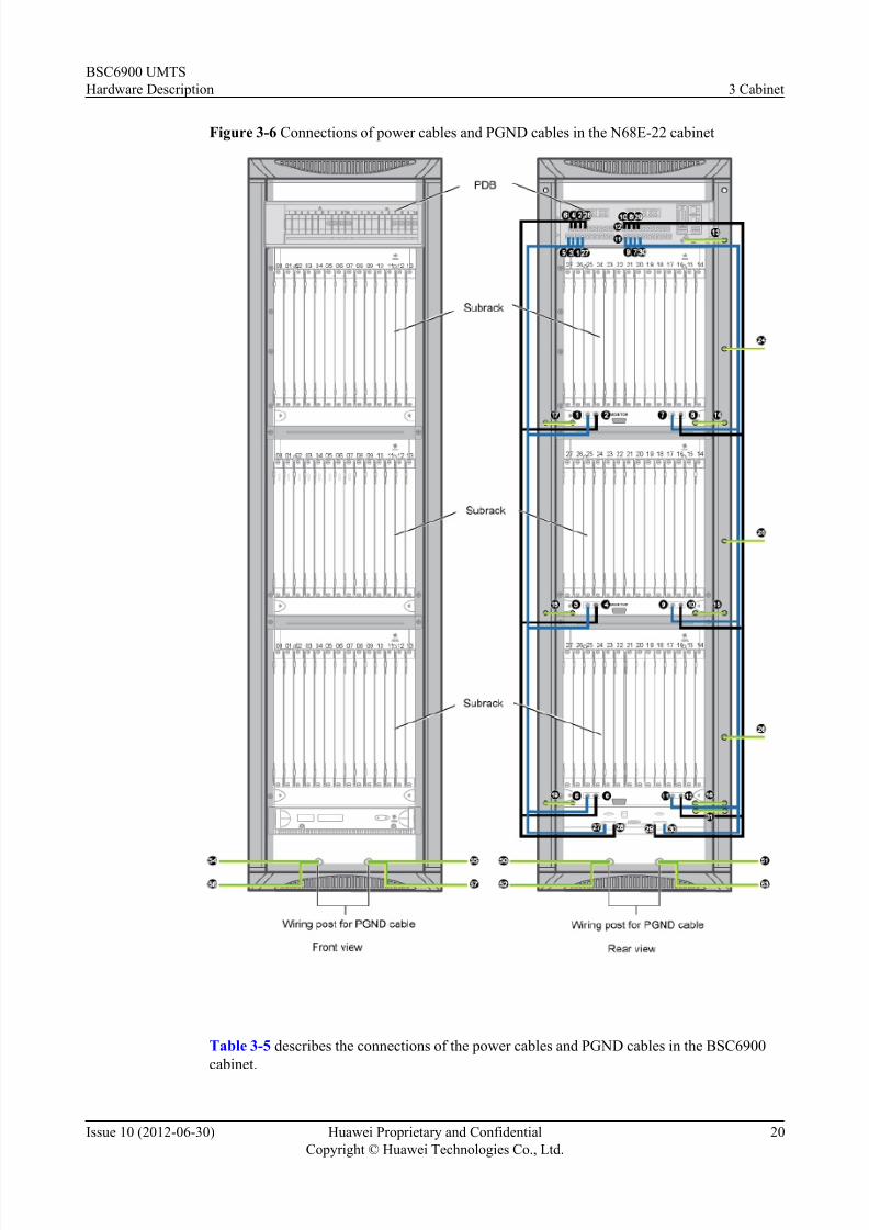
Figure 3-6 shows the connections of the power cables and PGND cables in the BSC6900
(N68E-22 cabinet).
BSC6900 UMTS
Hardware Description 3 Cabinet
Issue 10 (2012-06-30) Huawei Proprietary and Confidential
Copyright © Huawei Technologies Co., Ltd.
19
7/30/2019 BSC6900UMTS Hardware Description
http://slidepdf.com/reader/full/bsc6900umts-hardware-description 32/243
Figure 3-6 Connections of power cables and PGND cables in the N68E-22 cabinet
Table 3-5 describes the connections of the power cables and PGND cables in the BSC6900
cabinet.
BSC6900 UMTS
Hardware Description 3 Cabinet
Issue 10 (2012-06-30) Huawei Proprietary and Confidential
Copyright © Huawei Technologies Co., Ltd.
20

7/30/2019 BSC6900UMTS Hardware Description
http://slidepdf.com/reader/full/bsc6900umts-hardware-description 33/243
Table 3-5 Connections of power cables and PGND cables in the BSC6900 cabinet
SN Description
5, 6, 11, 12 Power cables for the bottom subrack
3, 4, 9, 10 Power cables for the middle subrack
1, 2, 7, 8 Power cables for the top subrack
13 PGND cable connecting the power distribution box and
the mounting bar
14, 15, 16, 17, 18, 19 PGND cables connecting the subracks and the mounting
bar
24, 25, 26 Inter-cabinet PGND cables
27, 28, 29, 30 Power cables for the independent fan subrack
31 PGND cable connecting the independent fan subrack and
the mounting bar
50-57 PGND cables for cabinet doors and side panels
Figure 3-7 shows the connections of the power cables and PGND cables in the Figure 3-7
(N68E-21-N cabinet).
BSC6900 UMTS
Hardware Description 3 Cabinet
Issue 10 (2012-06-30) Huawei Proprietary and Confidential
Copyright © Huawei Technologies Co., Ltd.
21

7/30/2019 BSC6900UMTS Hardware Description
http://slidepdf.com/reader/full/bsc6900umts-hardware-description 34/243
Figure 3-7 Connections of power cables and PGND cables in the N68E-21-N cabinet
Table 3-6 describes the connections of the power cables and PGND cables in the BSC6900
cabinet.
BSC6900 UMTS
Hardware Description 3 Cabinet
Issue 10 (2012-06-30) Huawei Proprietary and Confidential
Copyright © Huawei Technologies Co., Ltd.
22

7/30/2019 BSC6900UMTS Hardware Description
http://slidepdf.com/reader/full/bsc6900umts-hardware-description 35/243
Table 3-6 Connections of power cables and PGND cables in the BSC6900 cabinet
SN Description
5, 6, 11, 12 Power cables for the bottom subrack
3, 4, 9, 10 Power cables for the middle subrack
1, 2, 7, 8 Power cables for the top subrack
13 PGND cable connecting the power distribution box and
the mounting bar
14, 15, 16, 17, 18, 19 PGND cables connecting the subracks and the mounting
bar
20, 21 PGND cables for the cabinet busbar
24, 25, 26 PGND cables connecting the busbars of different
cabinets
50-57 PGND cables for cabinet doors and side panels
3.5.3 Distribution of Signal Cables for the MPR
The signal cables for the MPR refer to Ethernet cables, optical cables, trunk cables, clock signal
cables, and monitoring signal cables for the power distribution box.
Connections of Signal Cables for the MPRFigure 3-8 shows the connections of the signal cables for the MPR.
NOTE
l The types and number of the interface boards shown in Figure 3-8 are only taken as examples. The
actual configurations depend on the site planning.
l The installation positions and number of the Ethernet cables, optical cables, and trunk cables are
taken as examples. The actual configurations depend on the site planning.
BSC6900 UMTS
Hardware Description 3 Cabinet
Issue 10 (2012-06-30) Huawei Proprietary and Confidential
Copyright © Huawei Technologies Co., Ltd.
23

7/30/2019 BSC6900UMTS Hardware Description
http://slidepdf.com/reader/full/bsc6900umts-hardware-description 36/243
Figure 3-8 Connections of signal cables for the MPR
BSC6900 UMTS
Hardware Description 3 Cabinet
Issue 10 (2012-06-30) Huawei Proprietary and Confidential
Copyright © Huawei Technologies Co., Ltd.
24

7/30/2019 BSC6900UMTS Hardware Description
http://slidepdf.com/reader/full/bsc6900umts-hardware-description 37/243
Description About the Connections of Signal Cables for the MPR
Table 3-7 describes the connections of signal cables for the MPR.
Table 3-7 Connections of signal cables for the MPR SN Cable Name Connector
Type1/ ConnectionPosition1
ConnectorType2/ ConnectionPosition2
Remarks
1 Monitoring
signal cable for
the power
distribution box
DB15/Port
connecting the
power
distribution box
to the
independent fan
subrack
DB9/
MONITOR 1
port on the
independent fan
subrack
The cable is
mandatory and is
installed before
delivery. Only one
monitoring signal
cable for the power
distribution box isconfigured.
2, 3 GPS signal
transmission
cable connecting
GPS surge
protector to
GCGa board
SMA/ANT port
on the GCGa
board
Type N
connector/
Protect port of
the GPS surge
protector on top
of the cabinet
The cable is optional.
When installed, two
cables are required.
4 Ethernet cable
connecting SCUa
boards of different
subracks
RJ45/The
10/100/1000BA
SE-T0 port onthe SCUa board
in slot 6 of the
MPS
RJ45/The
10/100/1000BA
SE-T0 port onthe SCUa board
in slot 6 of the
EPS
l Straight-through
cable
l Installed beforedelivery
5 Ethernet cable
connecting SCUa
boards of
different
subracks
RJ45/The
10/100/1000BA
SE-T1 port on
the SCUa board
in slot 6 of the
MPS
RJ45/The
10/100/1000BA
SE-T1 port on
the SCUa board
in slot 7 of the
EPS
6 Ethernet cable
connecting SCUa
boards of
different
subracks
RJ45/The
10/100/1000BA
SE-T2 port on
the SCUa board
in slot 6 of the
MPS
RJ45/The
10/100/1000BA
SE-T0 port on
the SCUa board
in slot 6 of the
EPS
7 Ethernet cable
connecting SCUa
boards of
different
subracks
RJ45/The
10/100/1000BA
SE-T3 port on
the SCUa board
in slot 6 of the
MPS
RJ45/The
10/100/1000BA
SE-T1 port on
the SCUa board
in slot 7 of the
EPS
BSC6900 UMTS
Hardware Description 3 Cabinet
Issue 10 (2012-06-30) Huawei Proprietary and Confidential
Copyright © Huawei Technologies Co., Ltd.
25

7/30/2019 BSC6900UMTS Hardware Description
http://slidepdf.com/reader/full/bsc6900umts-hardware-description 38/243
SN Cable Name ConnectorType1/ ConnectionPosition1
ConnectorType2/ ConnectionPosition2
Remarks
8 Ethernet cable
connecting SCUa
boards of
different
subracks
RJ45/The
10/100/1000BA
SE-T0 port on
the SCUa board
in slot 7 of the
MPS
RJ45/The
10/100/1000BA
SE-T0 port on
the SCUa board
in slot 7 of the
EPS
9 Ethernet cable
connecting SCUa
boards of
different
subracks
RJ45/The
10/100/1000BA
SE-T1 port on
the SCUa board
in slot 7 of the
MPS
RJ45/The
10/100/1000BA
SE-T1 port on
the SCUa board
in slot 6 of the
EPS
10 Ethernet cable
connecting SCUa
boards of
different
subracks
RJ45/The
10/100/1000BA
SE-T2 port on
the SCUa board
in slot 7 of the
MPS
RJ45/The
10/100/1000BA
SE-T0 port on
the SCUa board
in slot 7 of the
EPS
11 Ethernet cable
connecting SCUa
boards of
differentsubracks
RJ45/The
10/100/1000BA
SE-T3 port on
the SCUa boardin slot 7 of the
MPS
RJ45/The
10/100/1000BA
SE-T1 port on
the SCUa boardin slot 6 of the
EPS
12, 13 BITS clock signal
cable
SMB or BNC/
BITS clock
source
SMB connector
(already
installed on the
BITS clock
signal cable)/
CLKIN0 port on
the GCUa/
GCGa board
The cable is optional.
When installed, two
cables are required.
14, 15 Line clock signal
cable
SMB/2M0 or
2M1 port on the
AOUa/POUa/
UOIa/AEUa
board
SMB/CLKIN0
or CLKIN1 port
on the GCUa/
GCGa board
Two to four,
optional, installed
when the EPS is
responsible for
receiving the line
clock signals
16 Y-shaped clock
signal cable
RJ45/
CLKOUT0 ports
on the GCUa/
GCGa boards in
slots 12 and 13
RJ45/CLKIN
port on the
SCUa board in
slot 6 of the EPS
Optional. The
number of cables to
be installed and their
actual installation
BSC6900 UMTS
Hardware Description 3 Cabinet
Issue 10 (2012-06-30) Huawei Proprietary and Confidential
Copyright © Huawei Technologies Co., Ltd.
26

7/30/2019 BSC6900UMTS Hardware Description
http://slidepdf.com/reader/full/bsc6900umts-hardware-description 39/243
SN Cable Name ConnectorType1/ ConnectionPosition1
ConnectorType2/ ConnectionPosition2
Remarks
17 positions depend on
the site planning.
Y-shaped clock
signal cable
RJ45/
CLKOUT1 ports
on the GCUa/
GCGa boards in
slots 12 and 13
RJ45/CLKIN
port on the
SCUa board in
slot 7 of the EPS
18 Y-shaped clock
signal cable
RJ45/
CLKOUT2 ports
on the GCUa/
GCGa boards in
slots 12 and 13
RJ45/CLKIN
port on the
SCUa board in
slot 6 of the EPS
19 Y-shaped clock signal cable
RJ45/CLKOUT3 ports
on the GCUa/
GCGa boards in
slots 12 and 13
RJ45/CLKIN port on the
SCUa board in
slot 7 of the EPS
20 Y-shaped clock
signal cable
RJ45/
CLKOUT4 ports
on the GCUa/
GCGa boards in
slots 12 and 13
RJ45/CLKIN
port on the
SCUa board in
slot 6 of the EPS
21 Y-shaped clock signal cable RJ45/CLKOUT5 ports
on the GCUa/
GCGa boards in
slots 12 and 13
RJ45/CLKIN port on the
SCUa board in
slot 7 of the EPS
22 Y-shaped clock
signal cable
RJ45/
CLKOUT6 ports
on the GCUa/
GCGa boards in
slots 12 and 13
RJ45/CLKIN
port on the
SCUa board in
slot 6 of the EPS
23 Y-shaped clock
signal cable
RJ45/
CLKOUT7 ports
on the GCUa/
GCGa boards in
slots 12 and 13
RJ45/CLKIN
port on the
SCUa board in
slot 7 of the EPS
24 Y-shaped clock
signal cable
RJ45/
CLKOUT8 ports
on the GCUa/
GCGa boards in
slots 12 and 13
RJ45/CLKIN
port on the
SCUa board in
slot 6 of the EPS
BSC6900 UMTS
Hardware Description 3 Cabinet
Issue 10 (2012-06-30) Huawei Proprietary and Confidential
Copyright © Huawei Technologies Co., Ltd.
27

7/30/2019 BSC6900UMTS Hardware Description
http://slidepdf.com/reader/full/bsc6900umts-hardware-description 40/243
SN Cable Name ConnectorType1/ ConnectionPosition1
ConnectorType2/ ConnectionPosition2
Remarks
25 Y-shaped clock
signal cable
RJ45/
CLKOUT9 ports
on GCUa/GCGa
boards in slots
12 and 13
RJ45/CLKIN
port on the
SCUa board in
slot 7 of the EPS
26 Trunk cable
connecting AEUa
board to other
devices
DB44/Electrical
port on the
AEUa board
Another device Optional. The
electrical port on the
AEUa board is taken
as an example. The
number of cables to
be installed and their
actual installation
positions depend on
the site planning.
The information here
is an example based
on overhead cabling.
27 Y-shaped trunk
cable connectingAEUa board to
other devices
Y-shaped DB44/
Electrical portson active and
standby AEUa
boards
Another device
28 Optical cable
connecting
GOUa/AOUa/
POUa/UOIa/
GOUc/AOUc/
POUc/UOIc
board to other
devices
LC/PC/Optical
port on the
GOUa/AOUa/
POUa/UOIa/
GOUc/AOUc/
POUc/UOIc
board
Another device Optional. The
number of optical
cables to be installed
and their actual
installation positions
depend on the site
planning. The
information here is
an example based on
overhead cabling.
29-32 Ethernet cable for
the OMUa board
RJ45/Ethernet
port on the
OMUa board
Another device l The cable is
mandatory. Two
to four cables are
required.
l Straight-through
cable. The
information here
is an example
based on
overhead
cabling.
BSC6900 UMTS
Hardware Description 3 Cabinet
Issue 10 (2012-06-30) Huawei Proprietary and Confidential
Copyright © Huawei Technologies Co., Ltd.
28

7/30/2019 BSC6900UMTS Hardware Description
http://slidepdf.com/reader/full/bsc6900umts-hardware-description 41/243
SN Cable Name ConnectorType1/ ConnectionPosition1
ConnectorType2/ ConnectionPosition2
Remarks
33 Ethernet cable
connecting FG2a/
FG2c board to
other devices
RJ45/Ethernet
port on the
FG2a/FG2c
board
Another device l Optional. The
number of
Ethernet cables to
be installed and
their actual
installation
positions depend
on the site
planning.
l Straight-through
cable. The
Ethernet cablecan be connected
to any Ethernet
port on the FG2a/
FG2c board. The
connection here
is only taken as
an example.
34 Monitoring
signal cable for
the independent
fan subrack
DB15/
MONITOR 0
port on the
independent fansubrack
DB9/Monitor
port on the rear
of the bottom
subrack
The cable is
mandatory and is
installed before
delivery. Only onemonitoring signal
cable for the
independent fan
subrack is
configured.
3.5.4 Distribution of Signal Cables for the EPR
The signal cables for the EPR refer to Ethernet cables, optical cables, trunk cables, andmonitoring signal cables for the power distribution box.
Connections of signal cables for the EPR
Figure 3-9 shows the connections of the signal cables for the EPR.
NOTE
l The types and number of the interface boards shown in Figure 3-9 are only taken as examples. The
actual configurations depend on the site planning.
l The installation positions and number of the Ethernet cables, optical cables, and trunk cables are
taken as examples. The actual configurations depend on the site planning.
BSC6900 UMTS
Hardware Description 3 Cabinet
Issue 10 (2012-06-30) Huawei Proprietary and Confidential
Copyright © Huawei Technologies Co., Ltd.
29

7/30/2019 BSC6900UMTS Hardware Description
http://slidepdf.com/reader/full/bsc6900umts-hardware-description 42/243
Figure 3-9 Connections of signal cables for the EPR
Description About the Connections of Signal Cables for the EPR
Table 3-8 describes the connections of signal cables for the EPR.
BSC6900 UMTS
Hardware Description 3 Cabinet
Issue 10 (2012-06-30) Huawei Proprietary and Confidential
Copyright © Huawei Technologies Co., Ltd.
30
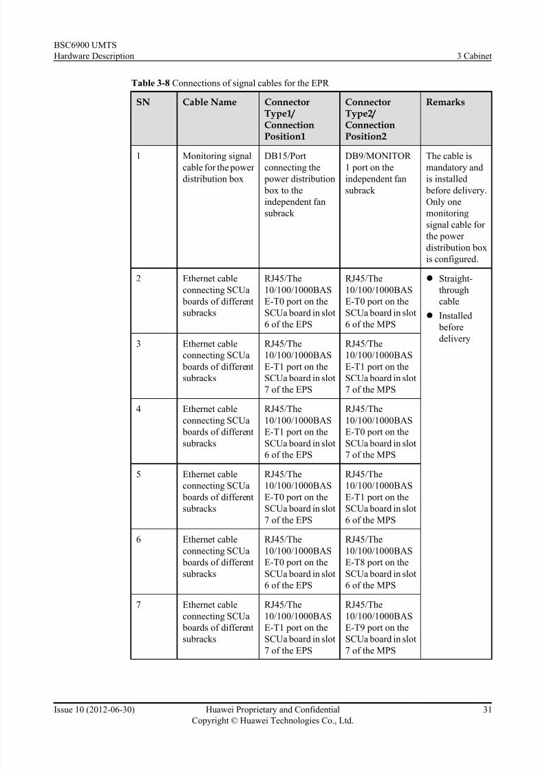
7/30/2019 BSC6900UMTS Hardware Description
http://slidepdf.com/reader/full/bsc6900umts-hardware-description 43/243
Table 3-8 Connections of signal cables for the EPR
SN Cable Name ConnectorType1/ Connection
Position1
ConnectorType2/ Connection
Position2
Remarks
1 Monitoring signal
cable for the power
distribution box
DB15/Port
connecting the
power distribution
box to the
independent fan
subrack
DB9/MONITOR
1 port on the
independent fan
subrack
The cable is
mandatory and
is installed
before delivery.
Only one
monitoring
signal cable for
the power
distribution box
is configured.
2 Ethernet cable
connecting SCUa
boards of different
subracks
RJ45/The
10/100/1000BAS
E-T0 port on the
SCUa board in slot
6 of the EPS
RJ45/The
10/100/1000BAS
E-T0 port on the
SCUa board in slot
6 of the MPS
l Straight-
through
cable
l Installed
before
delivery3 Ethernet cable
connecting SCUa
boards of different
subracks
RJ45/The
10/100/1000BAS
E-T1 port on the
SCUa board in slot
7 of the EPS
RJ45/The
10/100/1000BAS
E-T1 port on the
SCUa board in slot
7 of the MPS
4 Ethernet cable
connecting SCUa
boards of different
subracks
RJ45/The
10/100/1000BAS
E-T1 port on the
SCUa board in slot
6 of the EPS
RJ45/The
10/100/1000BAS
E-T0 port on the
SCUa board in slot
7 of the MPS
5 Ethernet cable
connecting SCUa
boards of different
subracks
RJ45/The
10/100/1000BAS
E-T0 port on the
SCUa board in slot
7 of the EPS
RJ45/The
10/100/1000BAS
E-T1 port on the
SCUa board in slot
6 of the MPS
6 Ethernet cableconnecting SCUa
boards of different
subracks
RJ45/The10/100/1000BAS
E-T0 port on the
SCUa board in slot
6 of the EPS
RJ45/The10/100/1000BAS
E-T8 port on the
SCUa board in slot
6 of the MPS
7 Ethernet cable
connecting SCUa
boards of different
subracks
RJ45/The
10/100/1000BAS
E-T1 port on the
SCUa board in slot
7 of the EPS
RJ45/The
10/100/1000BAS
E-T9 port on the
SCUa board in slot
7 of the MPS
BSC6900 UMTS
Hardware Description 3 Cabinet
Issue 10 (2012-06-30) Huawei Proprietary and Confidential
Copyright © Huawei Technologies Co., Ltd.
31
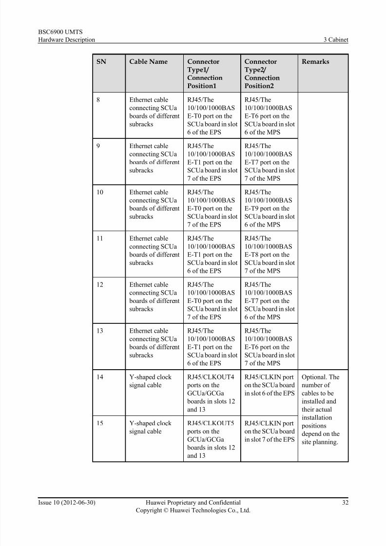
7/30/2019 BSC6900UMTS Hardware Description
http://slidepdf.com/reader/full/bsc6900umts-hardware-description 44/243
SN Cable Name ConnectorType1/ ConnectionPosition1
ConnectorType2/ ConnectionPosition2
Remarks
8 Ethernet cable
connecting SCUa
boards of different
subracks
RJ45/The
10/100/1000BAS
E-T0 port on the
SCUa board in slot
6 of the EPS
RJ45/The
10/100/1000BAS
E-T6 port on the
SCUa board in slot
6 of the MPS
9 Ethernet cable
connecting SCUa
boards of different
subracks
RJ45/The
10/100/1000BAS
E-T1 port on the
SCUa board in slot
7 of the EPS
RJ45/The
10/100/1000BAS
E-T7 port on the
SCUa board in slot
7 of the MPS
10 Ethernet cableconnecting SCUa
boards of different
subracks
RJ45/The10/100/1000BAS
E-T0 port on the
SCUa board in slot
7 of the EPS
RJ45/The10/100/1000BAS
E-T9 port on the
SCUa board in slot
6 of the MPS
11 Ethernet cable
connecting SCUa
boards of different
subracks
RJ45/The
10/100/1000BAS
E-T1 port on the
SCUa board in slot
6 of the EPS
RJ45/The
10/100/1000BAS
E-T8 port on the
SCUa board in slot
7 of the MPS
12 Ethernet cableconnecting SCUa
boards of different
subracks
RJ45/The10/100/1000BAS
E-T0 port on the
SCUa board in slot
7 of the EPS
RJ45/The10/100/1000BAS
E-T7 port on the
SCUa board in slot
6 of the MPS
13 Ethernet cable
connecting SCUa
boards of different
subracks
RJ45/The
10/100/1000BAS
E-T1 port on the
SCUa board in slot
6 of the EPS
RJ45/The
10/100/1000BAS
E-T6 port on the
SCUa board in slot
7 of the MPS
14 Y-shaped clock
signal cable
RJ45/CLKOUT4
ports on the
GCUa/GCGa
boards in slots 12
and 13
RJ45/CLKIN port
on the SCUa board
in slot 6 of the EPS
Optional. The
number of
cables to be
installed and
their actual
installation
positions
depend on the
site planning.
15 Y-shaped clock
signal cable
RJ45/CLKOUT5
ports on the
GCUa/GCGa
boards in slots 12
and 13
RJ45/CLKIN port
on the SCUa board
in slot 7 of the EPS
BSC6900 UMTS
Hardware Description 3 Cabinet
Issue 10 (2012-06-30) Huawei Proprietary and Confidential
Copyright © Huawei Technologies Co., Ltd.
32

7/30/2019 BSC6900UMTS Hardware Description
http://slidepdf.com/reader/full/bsc6900umts-hardware-description 45/243
SN Cable Name ConnectorType1/ ConnectionPosition1
ConnectorType2/ ConnectionPosition2
Remarks
16 Y-shaped clock
signal cable
RJ45/CLKOUT6
ports on the
GCUa/GCGa
boards in slots 12
and 13
RJ45/CLKIN port
on the SCUa board
in slot 6 of the EPS
17 Y-shaped clock
signal cable
RJ45/CLKOUT7
ports on the
GCUa/GCGa
boards in slots 12
and 13
RJ45/CLKIN port
on the SCUa board
in slot 7 of the EPS
18 Y-shaped clock signal cable
RJ45/CLKOUT8 ports on the
GCUa/GCGa
boards in slots 12
and 13
RJ45/CLKIN porton the SCUa board
in slot 6 of the EPS
19 Y-shaped clock
signal cable
RJ45/CLKOUT9
ports on GCUa/
GCGa boards in
slots 12 and 13
RJ45/CLKIN port
on the SCUa board
in slot 7 of the EPS
20 Trunk cable
connecting theAEUa board to
other devices
DB44/Electrical
port on the AEUa board
Another device Optional. The
electrical porton the AEUa
board is taken as
an example.
The number of
cables to be
installed and
their actual
installation
positions
depend on the
site planning.
Theinformation
here is an
example based
on overhead
cabling.
21 Y-shaped trunk
cable connecting
the AEUa board to
other devices
Y-shaped DB44/
Electrical ports on
active and standby
AEUa boards
Another device
BSC6900 UMTS
Hardware Description 3 Cabinet
Issue 10 (2012-06-30) Huawei Proprietary and Confidential
Copyright © Huawei Technologies Co., Ltd.
33

7/30/2019 BSC6900UMTS Hardware Description
http://slidepdf.com/reader/full/bsc6900umts-hardware-description 46/243
SN Cable Name ConnectorType1/ ConnectionPosition1
ConnectorType2/ ConnectionPosition2
Remarks
22, 23 Optical cable
connecting GOUa/
AOUa/POUa/
UOIa/GOUc/
AOUc/POUc/
UOIc board to
other devices
LC/PC/Optical
port on the GOUa/
AOUa/POUa/
UOIa/GOUc/
AOUc/POUc/
UOIc board
Another device Optional. The
number of
optical cables to
be installed and
their actual
installation
positions
depend on the
site planning.
The
information
here is anexample based
on overhead
cabling.
24, 25 Line clock signal
cable
SMB/2M0 or 2M1
port on the AOUa/
POUa/UOIa/
GOUa/GOUc/
AOUc/POUc/
UOIc/AEUa board
SMB/CLKIN0 or
CLKIN1 port on
the GCUa/GCGa
board in slot 12 or
13 of the MPS
The cable is
optional and is
installed only
when the cable
needs to be led
out from the
EPS in the EPR.
When installed,two to four
cables are
required.
26 Monitoring signal
cable for the
independent fan
subrack
DB15/MONITOR
0 port on the
independent fan
subrack
DB9/MONITOR
port on the rear of
the bottom
subrack
The cable is
mandatory and
is installed
before delivery.
Only one
monitoring
signal cable for
the independent
fan subrack is
configured.
BSC6900 UMTS
Hardware Description 3 Cabinet
Issue 10 (2012-06-30) Huawei Proprietary and Confidential
Copyright © Huawei Technologies Co., Ltd.
34

7/30/2019 BSC6900UMTS Hardware Description
http://slidepdf.com/reader/full/bsc6900umts-hardware-description 47/243
4 Components of the Cabinet
About This Chapter
Components of the cabinet involve the power distribution box, air defence subrack, rear cable
trough, subrack, independent fan subrack, rack.
4.1 Power Distribution Box
A power distribution box is installed inside each cabinet at the top.
4.2 Air Defence Subrack
The air defence subrack is installed between two subracks. It is used to form a straight-through
air channel. The air defence subrack is 1 U in height.
4.3 Rear Cable Trough
The rear cable trough is used for routing and binding of the cables of rear boards. Each rear cable
trough has three fiber management trays installed at the bottom to coil the optical cables.
4.4 Independent Fan Subrack
Besides the f an boxes configured in su bracks, the N68E-22 cabinet also has an independent fan
subrack configured at the bottom of the cabinet to improve the reliability of heat dissipation.
BSC6900 UMTS
Hardware Description 4 Components of the Cabinet
Issue 10 (2012-06-30) Huawei Proprietary and Confidential
Copyright © Huawei Technologies Co., Ltd.
35

7/30/2019 BSC6900UMTS Hardware Description
http://slidepdf.com/reader/full/bsc6900umts-hardware-description 48/243
4.1 Power Distribution Box
A power distribution box is installed inside each cabinet at the top.
The power distribution box provides lightning protection and power surge protection for the four
-48 V inputs and supplies two groups of power to the components in the cabinet. Each group
has four -48 V outputs and four RTN outputs. The power distribution box also detects the status
of input voltage and the output power, and generates audible and visual alarms when faults occur.
4.1.1 Front Panel of the Power Distribution Box
The components on the front panel of the power distribution box are the panel of the Power
Allocation Monitoring Unit (PAMU) and the power switches.
Figure 4-1 shows the front panel of the power distribution box.
Figure 4-1 Front panel of the power distribution box
(1) Panel of the PAMU board (2) RUN LED (3) ALM LED
(4) Mute switch (5) Power switches (6) Labels for power switches
NOTE
l For details about the PAMU board, see 6.12 PAMU Board.
l When the power distribution box is reset, the RUN and ALM LEDs turn on at the same time,
indicating that the PAMU board is performing self-check. As soon as the self-check is complete, the
RUN and ALM LEDs turn off. Then, the RUN and ALM LEDs display the operating status of the
power distribution box.
The mute switch is set to determine whether an audible alarm is generated.
l If you set the mute switch to I, the power distribution box generates an audible alarm when
it is faulty.
l If you set the mute switch to O, the power distribution box does not generate any audible
alarm when it is faulty.
The front panel of the power distribution box has two LEDs: RUN and ALM.
Table 4-1 describes the LEDs on the front panel of the power distribution box.
BSC6900 UMTS
Hardware Description 4 Components of the Cabinet
Issue 10 (2012-06-30) Huawei Proprietary and Confidential
Copyright © Huawei Technologies Co., Ltd.
36

7/30/2019 BSC6900UMTS Hardware Description
http://slidepdf.com/reader/full/bsc6900umts-hardware-description 49/243
Table 4-1 LEDs on the front panel of the power distribution box
LED Color Status Description
RUN Green ON for 1s and OFF for
1s
The PAMU board is functional and
communicates with the SCUa board properly.
ON for 0.25s and OFF
for 0.25s
The PAMU board is not working or it
does not communicate with the SCUa
board properly.
OFF There is no power supply to the PAMU
board or the power distribution box
does not work properly.
ALM Red OFF There is no alarm related to the power
distribution box.
ON The power distribution box is faulty.
During the self-check of the PAMU
board, however, the ALM LED is also
ON. This indicates that the ALM LED
is functional.
4.1.2 Rear Panel of the Power Distribution Box
The components on the r ear panel of the power distribution box are the power input terminal
block, power output terminal block, port used to connect the power distribution box to a subrack,
and a 2-hole grounding screw.
Figure 4-2 shows the rear panel of the power distribution box.
Figure 4-2 Rear panel of the power distribution box (WP1E01DPD)
(1) Power input terminal block (2) Power output terminal
block
(3) Port used to connect the power
distribution box to a subrack
(4) 2-hole grounding screw (5) J1 port (6) J2 port (port used to connect the power
distribution box to a EMU)
BSC6900 UMTS
Hardware Description 4 Components of the Cabinet
Issue 10 (2012-06-30) Huawei Proprietary and Confidential
Copyright © Huawei Technologies Co., Ltd.
37

7/30/2019 BSC6900UMTS Hardware Description
http://slidepdf.com/reader/full/bsc6900umts-hardware-description 50/243
NOTE
l Figure 4-2 shows only the main BSC6900-related ports on the power distribution box.
l On the power input terminal blocks of groups A and B, the wiring terminals for the -48 V power cable
are labeled 3(-) and 1(-) respectively, and the wiring terminals for the RTN power cable are labeled 3
(+) and 1(+) respectively.
l On the power output terminal blocks of groups A and B, the wiring terminals for the -48 V power cable
and RTN power cable are labeled NEG(-) and RTN(+), respectively.
4.1.3 Technical Specifications of the Power Distribution Box
This section describes the technical specifications of the input and output power supplies of the
power distribution box.
Table 4-2 describes the technical specifications of the power distribution box.
Table 4-2 Technical specifications of the power distribution box (WP1E01DPD)
Item Sub-item Specification
Input Rated input voltage -48 V DC or -60 V DC
Input voltage range -40 V DC to -72 V DC
Input mode Two groups of power inputs: A and B. Group A
consists of the power inputs A1+A2 and A3. Group
B consists of the power inputs B1+B2 and B3. Each
group has one or two -48 V DC or -60 V DC power
inputs.
Max. input current The maximum rated input current of each route is100 A.
Output Rated output voltage -48 V DC or -60 V DC
Output voltage
range
-40 V DC to -72 V DC
Output mode and
current
Two groups of power outputs: A and B. Each group
has one to four -48 V DC or -60 V DC power
outputs. The maximum rated output current of each
output is 50 A and that of each group is 100 A.
Each output is controlled by MCBs: A7 to A10 and
B7 to B10. These MCBs provide the power surge
protection function.
Output protection
specifications
The power surge protection point is 70 A. You need
to manually switch on the corresponding MCB
after the power surge protection.
Rated output power 9,600 W (Two groups of power outputs: A and B.
Each group has two -48 V DC power outputs.)
NOTEFor group A, power inputs A1+A2 correspond to power outputs A1 to A8, and power input A3 corresponds
to power outputs A9 and A10. Similarly, for group B, power inputs B1+B2 correspond to power outputs
B1 to B8, and power input B3 corresponds to power outputs B9 and B10.
BSC6900 UMTS
Hardware Description 4 Components of the Cabinet
Issue 10 (2012-06-30) Huawei Proprietary and Confidential
Copyright © Huawei Technologies Co., Ltd.
38

7/30/2019 BSC6900UMTS Hardware Description
http://slidepdf.com/reader/full/bsc6900umts-hardware-description 51/243
4.1.4 Distribution of Power Switches on the Power Distribution Box
The power distribution box of the cabinet has 20 (10 x 2) power outputs. There is a fixed relation between the eight outputs of the power distribution box and the components of the cabinet.
Figure 4-3 shows the relation between the eight power switches on the power distribution box
and the components in the MPR. Table 4-3 describes the relation between the eight power
switches on the power distribution box and the components in the MPR.
Figure 4-3 Relation between the power switches and components in the MPR
Table 4-3 Relation between the power switches and components in the MPR
Component Power Switch
Subrack 2 A8, B8
Subrack 1 A9, B9
Subrack 0 A10, B10
Independent fan subrack A7, B7
4.2 Air Defence Subrack
The air defence subrack is installed between two subracks. It is used to form a straight-throughair channel. The air defence subrack is 1 U in height.
BSC6900 UMTS
Hardware Description 4 Components of the Cabinet
Issue 10 (2012-06-30) Huawei Proprietary and Confidential
Copyright © Huawei Technologies Co., Ltd.
39

7/30/2019 BSC6900UMTS Hardware Description
http://slidepdf.com/reader/full/bsc6900umts-hardware-description 52/243
Physical appearance
Figure 4-4 shows the air defence subrack.
Figure 4-4 Air defence subrack
Dimensions
The dimensions of the air defence subrack are 44.45 mm (height) x 436 mm (width) x 476.1 mm
(depth).
4.3 Rear Cable Trough
The rear cable trough is used for routing and binding of the cables of rear boards. Each rear cable
trough has three fiber management trays installed at the bottom to coil the optical cables.
Figure 4-5 shows the rear cable trough.
Figure 4-5 Rear cable trough
4.4 Independent Fan Subrack
Besides the fan boxes configured in subracks, the N68E-22 cabinet also has an independent fan
subrack configured at the bottom of the cabinet to improve the reliability of heat dissipation.
BSC6900 UMTS
Hardware Description 4 Components of the Cabinet
Issue 10 (2012-06-30) Huawei Proprietary and Confidential
Copyright © Huawei Technologies Co., Ltd.
40

7/30/2019 BSC6900UMTS Hardware Description
http://slidepdf.com/reader/full/bsc6900umts-hardware-description 53/243
4.4.1 Appearance of the Independent Fan Subrack
The independent fan subrack is composed of the front panel, fan box, and the rear panel.
The fan box can be configured with either the PFCU or the PFCB board, which does not affect
the appearance of the independent fan subrack.
Front View of the Independent Fan Subrack
Figure 4-6 Front view of the independent fan subrack
(1) PFCB or PFCU board (2) Fans (3) Handle of the independent fan subrack
(4) Screw (5) LED on the fan box
NOTE
l The PFCU or the PFCB is the control unit of the fan box. For details on the PFCU board, see 6.14
PFCU Board. For details on the PFCB board, see 6.15 PFCB Board.l When the PFCU board is configured in the fan box of the independent fan subrack, the LEDs on the
fan box of the independent fan subrack are the same as those on the fan box in service subracks. For
details, see 5.3.1 Fan Box (Configured with the PFCU Board).
l When the PFCB board is configured in the fan box of the independent fan subrack, the LEDs on the
fan box of the independent fan subrack are the same as those on the fan box in service subracks. For
details, see 5.3.2 Fan Box (Configured with the PFCB Board) .
Rear View of the Independent Fan Subrack
Figure 4-7 Rear view of the independent fan subrack
(1) Monitor 1 Port, used to connect to the power
distribution box
(2) Power input port (3) Monitor 2 Port (Reserved)
BSC6900 UMTS
Hardware Description 4 Components of the Cabinet
Issue 10 (2012-06-30) Huawei Proprietary and Confidential
Copyright © Huawei Technologies Co., Ltd.
41

7/30/2019 BSC6900UMTS Hardware Description
http://slidepdf.com/reader/full/bsc6900umts-hardware-description 54/243
(4) Monitor 0 Port, used to connect to subracks (5) Monitor 3 Port (Reserved)
4.4.2 Technical Specifications of the Independent Fan Subrack
The technical specifications of the independent fan subrack refer to the dimensions, weight, power supply, maximum power consumption, fan speed, and Electromagnetic Compatibility
(EMC).
Table 4-4 describes the technical specifications of the independent fan subrack.
Table 4-4 Technical specifications of the independent fan subrack
Item Specification
Dimensions 86.1 mm (height) x 436 mm (width) x 480 mm (depth)
Weight Empty subrack:≤ 2.4 kg; subrack with fan boxes:≤ 6.9
kg
Power supply -48 V DC. The input voltage ranges from -40 V DC to -60
V DC.
Maximum power consumption ≤ 150 W
Fan speed < 5.0 m/s
EMC Meets the requirements in ETSI EN300 386 V1.2.1
(2000-03).
BSC6900 UMTS
Hardware Description 4 Components of the Cabinet
Issue 10 (2012-06-30) Huawei Proprietary and Confidential
Copyright © Huawei Technologies Co., Ltd.
42

7/30/2019 BSC6900UMTS Hardware Description
http://slidepdf.com/reader/full/bsc6900umts-hardware-description 55/243
5 Subracks
About This Chapter
This chapter describes subracks. Subracks are used to house boards and backplanes to form an
independent unit.
5.1 Classification of Subracks
Based on functions, subracks are classified into the main processing subrack (MPS) and extended
processing su brack (EPS).
5.2 Components of the Subrack
The main components of the subrack are the fan box, slots, front cable trough, and backplane.
5.3 Fan Box
The fan box is used for heat dissipation in the cabinet. Each subrack is configured with one fan
box.
5.4 Slots in the Subrack
The backplane is positioned in the center of the subrack, and the boards are installed on the front
and rear sides of the backplane.
5.5 DIP Switch on the Subrack
The DIP switch on the subrack is used to set the number of the subrack.
5.6 Configuration of the Subrack
BSC6900 subracks are classified into the MPS and EPS. This section describes the typicalconfigurations of these subracks.
5.7 Technical Specifications of the Subrack
The technical specifications of the subrack refer to the dimensions of the subrack, available space
height, weight, and power consumption in full configuration.
BSC6900 UMTS
Hardware Description 5 Subracks
Issue 10 (2012-06-30) Huawei Proprietary and Confidential
Copyright © Huawei Technologies Co., Ltd.
43

7/30/2019 BSC6900UMTS Hardware Description
http://slidepdf.com/reader/full/bsc6900umts-hardware-description 56/243
5.1 Classification of Subracks
Based on functions, subracks are classified into the main processing subrack (MPS) and extended
processing subrack (EPS).
MPS
As the main processing subrack, the MPS is configured in the MPR. Only one MPS is configured
in the BSC6900. The MPS processes the basic services of the BSC6900, performs operation and
maintenance, and provides clock signals for the system.
EPS
As the extended processing subrack, the EPS is configured in the MPR or EPR. It processes the
basic services of the BSC6900.
5.2 Components of the Subrack
The main components of the subrack are the fan box, slots, front cable trough, and backplane.
Structure of the Subrack
In compliance with the IEC60297 standard, each subrack is 19 inches in width and 12 U in
height. Figure 5-1 shows the structure of the subrack.
BSC6900 UMTS
Hardware Description 5 Subracks
Issue 10 (2012-06-30) Huawei Proprietary and Confidential
Copyright © Huawei Technologies Co., Ltd.
44

7/30/2019 BSC6900UMTS Hardware Description
http://slidepdf.com/reader/full/bsc6900umts-hardware-description 57/243
Figure 5-1 Structure of the subrack
(1) Fan box (2) Mounting ear (3) Guide rail
(4) Front cable trough (5) Boards (6) Grounding screw
BSC6900 UMTS
Hardware Description 5 Subracks
Issue 10 (2012-06-30) Huawei Proprietary and Confidential
Copyright © Huawei Technologies Co., Ltd.
45
7/30/2019 BSC6900UMTS Hardware Description
http://slidepdf.com/reader/full/bsc6900umts-hardware-description 58/243
(7) DC power input port (8) Port for the monitoring signal cable of the
power distribution box
(9) Cover plate of the DIP switch
Components
Table 5-1 describes the components of the subrack.
Table 5-1 Components of the subrack
Component Refer to...
Fan box 5.3 Fan Box
Slots in the subrack 5.4 Slots in the Subrack
Front cable trough The front cable trough is used to lead the cablesfrom the front of the subrack to both sides of the
cabinet.
Backplane The backplane is used to connect the boards in
the same subrack.
5.3 Fan Box
The fan box is used for heat dissipation in the cabinet. Each subrack is configured with one fan
box.
5.3.1 Fan Box (Configured with the PFCU Board)
This section describes the appearance of and LEDs on the fan box when the fan box is configured
with the PFCU board. This also describes the technical specifications of the fan box.
Appearance of Fan Box (Configured with the PFCU Board)
The fan box consists of the fans, board, LED, and handles.
Figure 5-2 shows the fan box.
BSC6900 UMTS
Hardware Description 5 Subracks
Issue 10 (2012-06-30) Huawei Proprietary and Confidential
Copyright © Huawei Technologies Co., Ltd.
46

7/30/2019 BSC6900UMTS Hardware Description
http://slidepdf.com/reader/full/bsc6900umts-hardware-description 59/243
Figure 5-2 Fan box (configured with the PFCU board)
(1) Power unit of the fan box (2) Fans (3) PFCU board
(4) LED on the fan box (5) Screws (6) Handles of the fan box
NOTE
l The power unit is inserted into the rear part of the fan box. It provides power supply for nine fans and
keeps the voltage stable through a stabilizing tube, to ensure normal operations of the fans.
l The PFCU board is the control unit of the fan box. For details on the PFCU board, see 6.14 PFCU
Board.
LED on the Fan Box (Configured with the PFCU Board)
The LED on the fan box blinks red or green, indicating different working status of the fan box.
Table 5-2 describes the different meanings that the LED indicates.
Table 5-2 LED on the fan box (configured with the PFCU board)
Color
Status Description
Gre
en
ON for 1s and OFF for 1s The fan box works normally (the fan box
is registered).
ON for 0.25s and OFF for 0.25s The fan box works normally (the fan box
is not registered).
BSC6900 UMTS
Hardware Description 5 Subracks
Issue 10 (2012-06-30) Huawei Proprietary and Confidential
Copyright © Huawei Technologies Co., Ltd.
47

7/30/2019 BSC6900UMTS Hardware Description
http://slidepdf.com/reader/full/bsc6900umts-hardware-description 60/243
Color
Status Description
Red ON for 1s and OFF for 1s The fan box is registered and has one of
the following problems:
l One-way power supply to the subrack
l Communication failure
l Fans ceasing to run or running at a too
low speed
l Fan box in an excessively high
temperature or temperature sensor
failure
ON for 0.25s and OFF for 0.25s The fan box is not registered and has one
of the following problems:
l One-way power supply to the subrack
l Fans ceasing to run or running at a too
low speed
l Fan box in an excessively high
temperature or temperature sensor
failure
NOTE
When the fan box is registered, the communication between the fan box and the SCUa board in the samesubrack is established. When the fan box is not registered, the communication between the fan box and the
SCUa board in the same subrack is not established.
Technical Specifications of the Fan Box (Configured with the PFCU Board)
The technical specifications of the fan box refer to the space height, voltage, maximum power,
detectable temperature range, and requirement for fan speed adjustment.
Table 5-3 lists the technical specifications of the fan box.
Table 5-3 Technical specifications of the fan box (configured with the PFCU board)
Item Specification
Space height 1.5 U (1 U = 44.45 mm)
Input voltage range -42 V DC to -60 V DC
Maximum power 150 W
Detectable temperature range -5°C to 55°C
Requirement for fan speed adjustment The speed of the fans can be adjusted from
55% to 100% of the full speed.
BSC6900 UMTS
Hardware Description 5 Subracks
Issue 10 (2012-06-30) Huawei Proprietary and Confidential
Copyright © Huawei Technologies Co., Ltd.
48

7/30/2019 BSC6900UMTS Hardware Description
http://slidepdf.com/reader/full/bsc6900umts-hardware-description 61/243
NOTE
When the BSC6900 is powered on, when a subrack is reset, or when the BSC6900 is upgraded, the fans
in the subrack run at full speed for a short period. This is the normal condition during system startup.
5.3.2 Fan Box (Configured with the PFCB Board)This section describes the appearance of and LEDs on the fan box when the fan box is configured
with the PFCB board. This also describes the technical specifications of the fan box.
Appearance of Fan Box (Configured with the PFCB Board)
The fan box consists of the fans, board, LED, and handles.
Figure 5-3 shows the fan box.
Figure 5-3 Fan box (configured with the PFCB board)
(1) PFCB Board (2) Fans (3) LED on the fan box
(4) Screw (5) Handles of the fan box
NOTE
l The PFCB board is the control unit of the fan box. For details on the PFCB board, see 6.15 PFCB
Board.
LED on the Fan Box (Configured with the PFCB Board)
The LED on the fan box blinks red or green, indicating different working status of the fan box.
Table 5-4 describes the different meanings that the LED indicates.
BSC6900 UMTS
Hardware Description 5 Subracks
Issue 10 (2012-06-30) Huawei Proprietary and Confidential
Copyright © Huawei Technologies Co., Ltd.
49
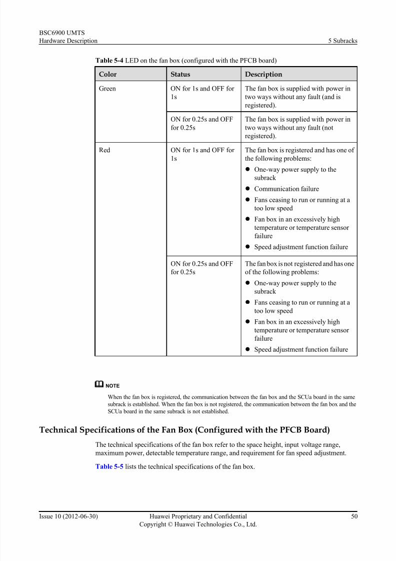
7/30/2019 BSC6900UMTS Hardware Description
http://slidepdf.com/reader/full/bsc6900umts-hardware-description 62/243
Table 5-4 LED on the fan box (configured with the PFCB board)
Color Status Description
Green ON for 1s and OFF for
1s
The fan box is supplied with power in
two ways without any fault (and isregistered).
ON for 0.25s and OFF
for 0.25s
The fan box is supplied with power in
two ways without any fault (not
registered).
Red ON for 1s and OFF for
1s
The fan box is registered and has one of
the following problems:
l One-way power supply to the
subrack
l Communication failure
l Fans ceasing to run or running at a
too low speed
l Fan box in an excessively high
temperature or temperature sensor
failure
l Speed adjustment function failure
ON for 0.25s and OFF
for 0.25s
The fan box is not registered and has one
of the following problems:
l One-way power supply to the
subrack l Fans ceasing to run or running at a
too low speed
l Fan box in an excessively high
temperature or temperature sensor
failure
l Speed adjustment function failure
NOTE
When the fan box is registered, the communication between the fan box and the SCUa board in the same
subrack is established. When the fan box is not registered, the communication between the fan box and the
SCUa board in the same subrack is not established.
Technical Specifications of the Fan Box (Configured with the PFCB Board)
The technical specifications of the fan box refer to the space height, input voltage range,
maximum power, detectable temperature range, and requirement for fan speed adjustment.
Table 5-5 lists the technical specifications of the fan box.
BSC6900 UMTS
Hardware Description 5 Subracks
Issue 10 (2012-06-30) Huawei Proprietary and Confidential
Copyright © Huawei Technologies Co., Ltd.
50

7/30/2019 BSC6900UMTS Hardware Description
http://slidepdf.com/reader/full/bsc6900umts-hardware-description 63/243
Table 5-5 Technical specifications of the fan box (configured with the PFCB board)
Item Specification
Space height 1.5 U (1 U = 44.45 mm)
Input voltage range -40 V DC to -57 V DC
Maximum power 150 W
Detectable temperature range -5°C to +55°C
Requirement for fan speed adjustment The speed of the fans can be adjusted from
55% to 100% of the full speed.
NOTE
When the BSC6900 is powered on, when a subrack is reset, or when the BSC6900 is upgraded, the fans
in the subrack run at full speed for a short period. This is the normal condition during system startup.
5.4 Slots in the Subrack
The backplane is positioned in the center of the subrack, and the boards are installed on the front
and rear sides of the backplane.
Figure 5-4 shows the structure of the subrack.
Figure 5-4 Structure of the subrack
(1) Front slot (2) Backplane (3) Rear slot
BSC6900 UMTS
Hardware Description 5 Subracks
Issue 10 (2012-06-30) Huawei Proprietary and Confidential
Copyright © Huawei Technologies Co., Ltd.
51

7/30/2019 BSC6900UMTS Hardware Description
http://slidepdf.com/reader/full/bsc6900umts-hardware-description 64/243
NOTE
l Each subrack provides a total of 28 slots. The 14 slots on the front side of the backplane are numbered
from 00 to 13, and those on the rear side from 14 to 27.
l Two neighboring slots, such as slot 00 and slot 01 or slot 02 and slot 03, can be configured as a pair
of active/standby slots. A pair of active and standby boards must be installed in a pair of active andstandby slots.
5.5 DIP Switch on the SubrackThe DIP switch on the subrack is used to set the number of the subrack.
Location of the DIP Switch
The DIP switch is located on the lower back of the subrack. For details on the location of the
DIP switch, see 5.2 Components of the Subrack .
Appearance
Figure 5-5 shows the cover plate for the DIP switch on the subrack.
Figure 5-5 Cover plate for the DIP switch on the subrack
Description about the DIP Switch
The DIP switch on the subrack has eight bits numbered in ascending order from 1 to 8. Thehigher the bit is, the more significant it is. Table 5-6 describes the bits.
BSC6900 UMTS
Hardware Description 5 Subracks
Issue 10 (2012-06-30) Huawei Proprietary and Confidential
Copyright © Huawei Technologies Co., Ltd.
52

7/30/2019 BSC6900UMTS Hardware Description
http://slidepdf.com/reader/full/bsc6900umts-hardware-description 65/243
Table 5-6 Description about the bits
Bit Description
1-5 Bits 1 to 5 are used for setting the subrack number. Bit 1 is the
least significant bit. If the bit is set to ON, it indicates 0. If the bitis set to OFF, it indicates 1.
6 Odd parity check bit
7 Reserved, undefined, generally set to ON
8 (the most significant
bit)
Startup type of the subrack, generally set to OFF.
Principle of the DIP Switch Setting As the DIP switch uses odd parity check, the number of 1s in the eight bits must be an odd
number. The method for setting the bits is as follows:
1. Set bit 1 to bit 5 as required.
2. Set bit 7 to ON.
3. Set bit 8 to OFF.
4. Check the number of 1s in the seven bits of the DIP switch. Note that the setting of bit 8
remains unchanged.
l If the number of 1s is even, set bit 6 to OFF.
l If the number of 1s is odd, set bit 6 to ON.
Assume that the subracks are numbered from 0 to 5 and that bit 8 is set to OFF. Table 5-7
describes the setting of the DIP switch in the case.
Table 5-7 Setting of the DIP switch
SubrackNo.
Bit Setting of the DIPSwitch
1 2 3 4 5 6 7 8
0 0 0 0 0 0 0 0 1
ON ON ON ON ON ON ON OFF
1 1 0 0 0 0 1 0 1
OFF ON ON ON ON OFF ON OFF
2 0 1 0 0 0 1 0 1
ON OFF ON ON ON OFF ON OFF
3 1 1 0 0 0 0 0 1
OFF OFF ON ON ON ON ON OFF
BSC6900 UMTS
Hardware Description 5 Subracks
Issue 10 (2012-06-30) Huawei Proprietary and Confidential
Copyright © Huawei Technologies Co., Ltd.
53

7/30/2019 BSC6900UMTS Hardware Description
http://slidepdf.com/reader/full/bsc6900umts-hardware-description 66/243
SubrackNo.
Bit Setting of the DIPSwitch
1 2 3 4 5 6 7 8
4 0 0 1 0 0 1 0 1
ON ON OFF ON ON OFF ON OFF
5 1 0 1 0 0 0 0 1
OFF ON OFF ON ON ON ON OFF
5.6 Configuration of the Subrack
BSC6900 subracks are classified into the MPS and EPS. This section describes the typical
configurations of these subracks.
5.6.1 Configuration of the MPS
The MPS is configured in the MPR. Each BSC6900 cabinet must be configured with one MPS.
The boards that can be installed in the MPS are the OMUa board, SCUa board, SPUa/SPUb
board, GCUa board, GCGa board, DPUb/DPUe board, AEUa board, AOUa/AOUc board, UOIa/
UOIc board, PEUa board, POUa/POUc board, FG2a/FG2c board, and GOUa/GOUc board.
Figure 5-6 shows the MPS in full configuration.
Figure 5-6 MPS in full configuration
BSC6900 UMTS
Hardware Description 5 Subracks
Issue 10 (2012-06-30) Huawei Proprietary and Confidential
Copyright © Huawei Technologies Co., Ltd.
54

7/30/2019 BSC6900UMTS Hardware Description
http://slidepdf.com/reader/full/bsc6900umts-hardware-description 67/243
NOTE
l The INT board (interface board) can be the AEUa board, AOUa/AOUc board, UOIa/UOIc board, PEUa
board, POUa/POUc board, FG2a/FG2c board, or GOUa/GOUc board.
l If customers purchase also the Nastar product of Huawei, customers need to install the SAU board in
the MPS or EPS of the BSC6900 cabinet (the SAU board occupies two slots that work in active/standbymode). For details on how to install the SAU board, how to install the software on the SAU board, and
how to maintain the SAU board, see the SAU User Guide of Nastar documents.
5.6.2 Configuration of the EPS
The EPS is configured in the MPR or EPR. The BSC6900 cabinet can be configured with zero
to five EPSs.
The boards that can be installed in the EPS are the SCUa board, SPUa/SPUb board, DPUb/DPUe
board, AEUa board, AOUa/AOUc board, UOIa/UOIc board, PEUa board, POUa/POUc board,
FG2a/FG2c board, and GOUa/GOUc board.
Figure 5-7 shows the EPS in full configuration.
Figure 5-7 EPS in full configuration
NOTE
l The INT board (interface board) can be the AEUa board, AOUa/AOUc board, UOIa/UOIc board, PEUa board, POUa/POUC board, FG2a/FG2c board, or GOUa/GOUc board.
l If customers purchase also the Nastar product of Huawei, customers need to install the SAU board in
the MPS or EPS of the BSC6900 cabinet (the SAU board occupies two slots that work in active/standby
mode). For details on how to install the SAU board, how to install the software on the SAU board, and
how to maintain the SAU board, see the SAU User Guide of Nastar documents.
5.7 Technical Specifications of the Subrack
The technical specifications of the subrack refer to the dimensions of the subrack, available space
height, weight, and power consumption in full configuration.
Table 5-8 describes the technical specifications of the subrack.
BSC6900 UMTS
Hardware Description 5 Subracks
Issue 10 (2012-06-30) Huawei Proprietary and Confidential
Copyright © Huawei Technologies Co., Ltd.
55

7/30/2019 BSC6900UMTS Hardware Description
http://slidepdf.com/reader/full/bsc6900umts-hardware-description 68/243
Table 5-8 Technical specifications of the subrack
Item Specification
Dimensions 530.6 mm (height) x 436 mm (width) x 480 mm (depth)
Available space height 12 U (1 U = 44.45 mm = 1.75 inches)
Weight Empty subrack: 25 kg; subrack configured with boards:≤
57 kg
Power consumption in full
configuration
l MPS:≤ 1,600 W
l EPS:≤ 1,450 W
BSC6900 UMTS
Hardware Description 5 Subracks
Issue 10 (2012-06-30) Huawei Proprietary and Confidential
Copyright © Huawei Technologies Co., Ltd.
56

7/30/2019 BSC6900UMTS Hardware Description
http://slidepdf.com/reader/full/bsc6900umts-hardware-description 69/243
6 Boards
About This Chapter
This chapter describes the boards supported by the BSC6900.
The BSC6900 boards perform different functions through the loading of different software.
Table 6-1 describes the BSC6900 boards.
NOTE
If a board is configured in independent mode, its slot can switch a maximum of 4096 timeslots. If boards are
configured in active/standby mode, their slots can switch a maximum of 7168 timeslots.
Table 6-1 Classification of the BSC6900 boards
Board Logical Function Function Description Board Name
AEUa ATM - 32-port ATM over
E1/T1/J1 interface
Unit REV:a
AOUa ATM - 2-port ATM over
channelized Optical
STM-1/OC-3
interface Unit
REV:a
AOUc ATM - 4-port ATM over
channelized Optical
STM-1/OC-3
interface Unit
REV:c
DPUb UUP (UMTS RNC User
plane Process)
UMTS RNC user plane
processing
Data Processing
Unit REV:b
DPUe UUP (UMTS RNC User
plane Process)
UMTS RNC user plane
processing
Data Processing
Unit REV:e
BSC6900 UMTS
Hardware Description 6 Boards
Issue 10 (2012-06-30) Huawei Proprietary and Confidential
Copyright © Huawei Technologies Co., Ltd.
57

7/30/2019 BSC6900UMTS Hardware Description
http://slidepdf.com/reader/full/bsc6900umts-hardware-description 70/243
Board Logical Function Function Description Board Name
FG2a IP - 8-port FE or 2-port
electronic GE
interface unit REV:a
FG2c IP - 12-port FE or 4-port
electronic GE
interface unit REV:c
GCUa Clock - General Clock Unit
REV:a
GCGa Clock with GPS - General Clock Unit
with GPS REV:a
GOUa IP - 2-port packet over
GE Optical interface
Unit REV:a
GOUc IP - 4-port packet over
GE Optical interface
Unit REV:c
OMUa OAM (Operation,
Administration and
Maintenance)
OM management Operation and
Maintenance Unit
REV:a
PEUa IP - 32-port Packet over
E1/T1/J1 interface
Unit REV:a
POUa IP - 2-port IP over
channelized Optical
STM-1/OC-3
interface Unit
REV:a
POUc IP - 4-port IP over
channelized Optical
STM-1/OC-3
interface Unit
REV:c
SCUa MAC Switching - GE Switching
network and Control
Unit REV:a
SPUa UCP (UMTS RNC Control
plane Process)
UMTS RNC control plane
processing
Signaling
Processing Unit
REV:aRUCP (Resource
Management and UMTS
RNC Control plane
Process)
Resource management
and UMTS RNC control
plane processing
BSC6900 UMTS
Hardware Description 6 Boards
Issue 10 (2012-06-30) Huawei Proprietary and Confidential
Copyright © Huawei Technologies Co., Ltd.
58

7/30/2019 BSC6900UMTS Hardware Description
http://slidepdf.com/reader/full/bsc6900umts-hardware-description 71/243
Board Logical Function Function Description Board Name
SPUb UCP (UMTS RNC Control
plane Process)
UMTS RNC control plane
processing
Signaling
Processing Unit
REV:bRUCP (ResourceManagement and UMTS
RNC Control plane
Process)
Resource managementand UMTS RNC control
plane processing
UOIa ATM - 4-port ATM/Packet
over Unchannelized
Optical STM-1/
OC-3c Interface unit
REV:a
UOIc ATM - 8-port ATM/Packet
over UnchannelizedOptical STM-1/
OC-3c Interface unit
REV:c
PAMU - - Power Allocation
Monitoring Unit
PFCU - - Fan Control Unit
PFCB - - Fan Control Board
6.1 AEUa Board
AEUa refers to 32-port ATM over E1/T1/J1 interface Unit REV:a. The AEUa board is optional.
It can be installed either in the MPS or in the the EPS. The number of AEUa boards to be installed
depends on site requirements. For the MPS, the AEUa board can be installed in slots 14 to 19
and slots 24 to 27. For the EPS, the AEUa board can be installed in slots 14 to 27.
6.2 AOUa Board
AOUa refers to 2-port ATM over channelized Optical STM-1/OC-3 interface Unit REV:a. The
AOUa board is optional. It can be installed either in the MPS or in the EPS. The number of
AOUa boards to be installed depends on site requirements. For the MPS, the AOUa board can
be installed in slots 14 to 19 and slots 24 to 27. For the EPS, the AOUa board can be installed
in slots 14 to 27.
6.3 AOUc Board
AOUc refers to 4-port ATM over channelized Optical STM-1/OC-3 interface Unit REV:c. The
AOUc board is optional. It can be installed in the MPS and in the EPS. The number of AOUc
boards to be installed depends on site requirements. For the MPS, the AOUc board can be
installed in slots 14 to 19 and slots 24 to 27. For the EPS, the AOUc board can be installed in
slots 14 to 27.
6.4 DPUb Board
DPUb refers to Data Processing Unit REV:b. The DPUb board is optional. For the MPS, two to
ten DPUb boards can be installed in slots 0 to 5, slots 8 to 11, slots 14 to 19, and slots 24 to 27.
For the EPS, two to twelve DPUb boards can be installed in slots 0 to 5, slots 8 to 27.
6.5 DPUe Board
BSC6900 UMTS
Hardware Description 6 Boards
Issue 10 (2012-06-30) Huawei Proprietary and Confidential
Copyright © Huawei Technologies Co., Ltd.
59

7/30/2019 BSC6900UMTS Hardware Description
http://slidepdf.com/reader/full/bsc6900umts-hardware-description 72/243
DPUe refers to Data Processing Unit REV:e. The DPUe board is optional. For the MPS, two to
ten DPUe boards can be installed in slots 0 to 5, slots 8 to 11, slots 14 to 19, and slots 24 to 27.
For the EPS, two to twelve DPUe boards can be installed in slots 0 to 5, slots 8 to 27.
6.6 FG2a Board
FG2a refers to 8-port FE or 2-port electronic GE interface unit REV:a. The FG2a board isoptional. It can be installed either in the MPS or in the EPS. The number of FG2a boards to be
installed depends on site requirements. For the MPS, the FG2a board can be installed in slots
14 to 19 and slots 24 to 27. For the EPS, the FG2a board can be installed in slots 14 to 27.
6.7 FG2c Board
FG2c refers to 12-port FE or 4-port electronic GE interface unit REV:c. The FG2c board is
optional. It can be installed in the MPS and in the EPS. The number of FG2c boards to be installed
depends on site requirements. For the MPS, the FG2c board can be installed in slots 14 to 19.
For the EPS, the FG2c board can be installed in slots 14 to 23.
6.8 GCUa/GCGa Board
GCUa refers to General Clock Unit REV:a. GCGa refers to General Clock Unit with GPS REV:a.The GCUa/GCGa board is mandatory. Two GCUa/GCGa boards must be installed in slots 12
and 13 in the MPS.
6.9 GOUa Board
GOUa refers to 2-port packet over GE Optical interface Unit REV:a. The GOUa board is
optional. It can be installed in the MPS, EPS. The number of GOUa boards to be installed depends
on site requir ements. For the MPS, the GOUa board can be installed in slots 14 to 19 and slots
24 to 27. For the EPS, the GOUa board can be installed in slots 14 to 27.
6.10 GOUc Board
GOUc refers to 4-port packet over GE Optical interface Unit REV:c. The GOUc board is
optional. It can be installed in the MPS and in the EPS. The number of GOUc boards to be
installed depends on site requirements. For the MPS, the GOUc board can be installed in slots14 to 19. For the EPS, the GOUc board can be installed in slots 14 to 23.
6.11 OMUa Board
OMUa refers to Operation and Maintenance Unit REV:a. One or two OMUa boards must be
configured in the BSC6900. The width of the OMUa board is twice the width of other boards.
Therefore, one OMUa board occupies two slots. The board can be installed in slots 0 to 3, slots
20 to 23, or slots 24 to 27 in the MPS. Slots 20 to 23 are recommended.
6.12 PAMU Board
PAMU refers to Power Allocation Monitoring Unit. The PAMU board is installed in the power
distribution box at the top of the cabinet. Each power distribution box accommodates one PAMU
board.
6.13 PEUa Board
PEUa refers to 32-port Packet over E1/T1/J1 interface Unit REV:a. The PEUa board is optional.
It can be installed either in the MPS or in the EPS. The number of PEUa boards to be installed
depends on site requirements. For the MPS, the PEUa board can be installed in slots 14 to 19
and slots 24 to 27. For the EPS, the PEUa board can be installed in slots 14 to 27.
6.14 PFCU Board
PFCU refers to Fan Control Unit. The PFCU board is installed in the front of the fan box. Each
fan box is configured with one PFCU board.
6.15 PFCB Board
PFCB refers to Fan Control Board. The PFCB board is installed in the front of the fan box. Eachfan box is configured with one PFCB board.
BSC6900 UMTS
Hardware Description 6 Boards
Issue 10 (2012-06-30) Huawei Proprietary and Confidential
Copyright © Huawei Technologies Co., Ltd.
60

7/30/2019 BSC6900UMTS Hardware Description
http://slidepdf.com/reader/full/bsc6900umts-hardware-description 73/243
6.16 POUa Board
POUa refers to 2-port IP over channelized Optical STM-1/OC-3 interface Unit REV:a. The
POUa board is optional. It can be installed either in the MPS or in the EPS. The number of POUa
boards to be installed depends on site requirements. For the MPS, the POUa board can be
installed in slots 14 to 19 and slots 24 to 27. For the EPS, the POUa board can be installed in
slots 14 to 27.
6.17 POUc Board
POUc refers to 4-port IP over channelized Optical STM-1/OC-3 interface Unit REV:c. The
POUc board is optional. It can be installed in the MPS and in the EPS. The number of POUc
boards to be installed depends on site requirements. For the MPS, the POUc board can be
installed in slots 14 to 19 and slots 24 to 27. For the EPS, the POUc board can be installed in
slots 14 to 27.
6.18 SCUa Board
SCUa refers to GE Switching network and Control Unit REV:a. The SCUa board is mandatory.
Two SCUa boards must be installed in slots 6 and 7 in the MPS/EPS.
6.19 SPUa Board
SPUa refers to Signaling Processing Unit REV:a. The SPUa board is optional. Two to ten SPUa
boards can be installed in the MPS/EPS. For the MPS, the SPUa boards can be installed in slots
0 to 5, slots 8 to 11, slots 14 to 19, and slots 24 to 27. For the EPS, the SPUa boards can be
installed in slots 0 to 5 and slots 8 to 27.
6.20 SPUb Board
SPUb refers to Signaling Processing Unit REV:b. The SPUb board is optional. Two to ten SPUb
boards can be installed in the MPS and in the EPS. For the MPS, the SPUb boards can be installed
in slots 0 to 5, slots 8 to 11, slots 14 to 19, and slots 24 to 27. For the EPS, the SPUb boards can
be installed in slots 0 to 5, slots 8 to 13, and slots 14 to 27.
6.21 UOIa BoardUOIa refers to 4-port ATM/Packet over Unchannelized Optical STM-1/OC-3c Interface unit
REV:a. The UOIa board is optional. It can be installed either in the MPS or in the EPS. The
number of UOIa boards to be installed depends on site requirements. For the MPS, the UOIa
board can be installed in slots 14 to 19 and slots 24 to 27. For the EPS, the UOIa board can be
installed in slots 14 to 27.
6.22 UOIc Board
UOIc refers to 8-port ATM/Packet over Unchannelized Optical STM-1/OC-3c Interface unit
REV:c. The UOIc board is optional. It can be installed in the MPS and in the EPS. The number
of UOIc boar ds to be installed depends on site requirements. For the MPS, the UOIc board can
be installed in slots 16 to 19. For the EPS, the UOIc board can be installed in slots 16 to 23.
BSC6900 UMTS
Hardware Description 6 Boards
Issue 10 (2012-06-30) Huawei Proprietary and Confidential
Copyright © Huawei Technologies Co., Ltd.
61
7/30/2019 BSC6900UMTS Hardware Description
http://slidepdf.com/reader/full/bsc6900umts-hardware-description 74/243
6.1 AEUa Board
AEUa refers to 32-port ATM over E1/T1/J1 interface Unit REV:a. The AEUa board is optional.
It can be installed either in the MPS or in the the EPS. The number of AEUa boards to be installed
depends on site requirements. For the MPS, the AEUa board can be installed in slots 14 to 19
and slots 24 to 27. For the EPS, the AEUa board can be installed in slots 14 to 27.
NOTE
If the OMUa boards are not installed in slots 20 to 23 of the MPS, the AEUa boards can be installed in slots 20
to 23 of the MPS.
6.1.1 Functions of the AEUa Board
As an interface board, the AEUa board supports ATM over E1/T1/J1 transmission.
The AEUa board performs the following functions:
l Provides 32 channels of ATM over E1s/T1s/J1s
l Provides 32 IMA groups or 32 UNI links
l Supports the Iub interfaces
l Provides the fractional ATM and the fractional IMA functions
l Supports the timeslot cross-connection function
l Receives clock signals from the Iu interface and transmits clock signals to the GCUa/GCGa
board
6.1.2 Panel of the AEUa BoardThere are LEDs and ports on the panel of the AEUa board.
Figure 6-1 shows the panel of the AEUa board.
BSC6900 UMTS
Hardware Description 6 Boards
Issue 10 (2012-06-30) Huawei Proprietary and Confidential
Copyright © Huawei Technologies Co., Ltd.
62

7/30/2019 BSC6900UMTS Hardware Description
http://slidepdf.com/reader/full/bsc6900umts-hardware-description 75/243
Figure 6-1 Panel of the AEUa board
6.1.3 LEDs on the AEUa Board
There are three LEDs on the AEUa board: RUN, ALM, and ACT.
Table 6-2 describes the LEDs on the AEUa board.
Table 6-2 LEDs on the AEUa boardLED Color Status Description
RUN Green ON for 1s and OFF for
1s
The board is functional.
ON for 0.125s and OFF
for 0.125s
The board is in loading state.
ON There is power supply, but the board
is faulty.
OFF There is no power supply, or the board
is faulty.
BSC6900 UMTS
Hardware Description 6 Boards
Issue 10 (2012-06-30) Huawei Proprietary and Confidential
Copyright © Huawei Technologies Co., Ltd.
63

7/30/2019 BSC6900UMTS Hardware Description
http://slidepdf.com/reader/full/bsc6900umts-hardware-description 76/243
LED Color Status Description
ALM Red OFF There is no alarm.
ON or blinking There is a fault alarm.
ACT Green ON The board is in active mode.
OFF The board is in standby mode.
6.1.4 Ports on the AEUa Board
There are four E1/T1 ports and two clock signal output ports on the AEUa board.
Table 6-3 describes the ports on the AEUa board.
Table 6-3 Ports on the AEUa board
Port Function Connector Type
E1/T1 (0-7) E1/T1 port, used to transmit and receive E1/
T1 signals on channels 0-7
DB44
E1/T1 (8-15) E1/T1 port, used to transmit and receive E1/
T1 signals on channels 8-15
DB44
E1/T1 (16-23) E1/T1 port, used to transmit and receive E1/
T1 signals on channels 16-23
DB44
E1/T1 (24-31) E1/T1 port, used to transmit and receive E1/
T1 signals on channels 24-31
DB44
2M0 and 2M1 Ports for 2 MHz clock signal outputs SMB male
connector
6.1.5 DIP Switches on the AEUa Board
The AEUa board provides five DIP switches, namely, S2, S4, S6, S8, and S10.
Layout of the DIP Switches
Figure 6-2 shows the layout of the DIP switches on the AEUa board.
BSC6900 UMTS
Hardware Description 6 Boards
Issue 10 (2012-06-30) Huawei Proprietary and Confidential
Copyright © Huawei Technologies Co., Ltd.
64

7/30/2019 BSC6900UMTS Hardware Description
http://slidepdf.com/reader/full/bsc6900umts-hardware-description 77/243
Figure 6-2 Layout of the DIP switches on the AEUa board
(1) Sub-board (2) Bottom plate
BSC6900 UMTS
Hardware Description 6 Boards
Issue 10 (2012-06-30) Huawei Proprietary and Confidential
Copyright © Huawei Technologies Co., Ltd.
65

7/30/2019 BSC6900UMTS Hardware Description
http://slidepdf.com/reader/full/bsc6900umts-hardware-description 78/243
NOTE
l All DIP switches are on the front panel of the sub-board. The front panel is combined with the bottom
plate, so the DIP switches are not exposed.
l DIP switches S2, S4, S6, S8, and S10 are set from the side. As shown in Figure 6-2, there are two
square holes between DIP switches, one between S2 and S4, and the other between S8 and S6. Throughthe two holes, you can set S2, S4, S8, and S6. DIP switch S10 is located in the right corner of the sub-
board, and thus you can set S10 along the side. The direction of the arrow in Figure 6-2 is to turn
inwards. To set the bits of S2, S4, S6, or S8 to ON, turn them inwards. To set the bits of S2, S4, S6, or
S8 to OFF, turn them outwards. To set the bits of S10 to ON, turn them outwards. To set the bits of
S10 to OFF, turn them inwards.
l You can also run the SET E1T1 command on the LMT to set S10. If there is any inconsistency between
the physical setting of S10 on the AEUa board and the setting of S10 by command, take the setting by
command as the criterion. By default, the working mode of S10 is set to E1. You can also run the SET
E1T1 command on the LMT to change the working mode of S10 from E1 mode to E1 balanced mode,
E1 unbalanced mode, or T1 mode. When you run the SET E1T1 command to set the support for
balanced and unbalanced modes parameter to No and set the working mode of S10 to E1, you must
also manually set the bits of S10 to set the working mode of S10 to E1 balanced mode or E1 unbalanced
mode.l If signals are transmitted in E1 unbalanced mode, the signals are transmitted through the 75-ohm coaxial
cable and the TX end of the cable is grounded, that is, the corresponding DIP bit is set to ON. If signals
are transmitted in E1(T1) balanced mode, the signals are transmitted through the 120-ohm twisted pair
cable and the TX end of the cable is not grounded, that is, the corresponding DIP bit is set to OFF.
Description of the DIP Switches
DIP switches S2, S4, S6, and S8 on the AEUa board are used to enable or disable the grounding
of 0 to 31 E1s/T1/J1s at the TX end. DIP switch S10 is used to set the working mode to E1
balanced mode, E1 unbalanced mode, T1 mode, or J1 mode. Table 6-4 describes S2, S4, S6,
S8, and S10.
Table 6-4 Description of the DIP switches on the AEUa board
DIP Switch Bit Description Setting ofDIP Bit
Meaning
S2 1-8 TX ground switch
of E1s/T1s/J1s 24
to 31
ON Setting the working
mode to E1 unbalanced
mode
OFF Setting the working
mode to other modes
S4 1-8 TX ground switch
of E1s/T1s/J1s 16
to 23
ON Setting the working
mode to E1 unbalanced
mode
OFF Setting the working
mode to other modes
S6 1-8 TX ground switch
of E1s/T1s/J1s 0
to 7
ON Setting the working
mode to E1 unbalanced
mode
OFF Setting the working
mode to other modes
BSC6900 UMTS
Hardware Description 6 Boards
Issue 10 (2012-06-30) Huawei Proprietary and Confidential
Copyright © Huawei Technologies Co., Ltd.
66

7/30/2019 BSC6900UMTS Hardware Description
http://slidepdf.com/reader/full/bsc6900umts-hardware-description 79/243
DIP Switch Bit Description Setting ofDIP Bit
Meaning
S8 1-8 TX ground switch
of E1s/T1s/J1s 8
to 15
ON Setting the working
mode to E1 unbalanced
mode
OFF Setting the working
mode to other modes
S10 1-2 DIP switch for
setting the
working mode,
consisting of two
bits
(ON, ON) Setting the working
mode to E1 unbalanced
mode
(OFF, ON) Setting the working
mode to E1 balanced
mode
(ON, OFF) Setting the working
mode to T1 mode
(OFF, OFF) Setting the working
mode to J1 mode
NOTE
All the DIP switches are set to E1 balanced mode by default, that is, all the bits of S2, S4, S6, and S8 are
set to OFF. For S10, the first bit is set to OFF, and the second bit to ON.
6.1.6 Technical Specifications of the AEUa Board
The technical specifications of the AEUa board consist of hardware specifications and
specifications of the board processing capability. The hardware specifications consist of the
dimensions, power supply, power consumption, weight, operating temperature, and relative
humidity.
Table 6-5 describes the hardware specifications of the AEUa board.
Table 6-5 Hardware specifications of the AEUa board
Item Specification
Dimensions 248 mm x 32.3mm x 395.4 mm
Power supply Two -48 V DC working in active/standby mode.
The backplane of the subrack is responsible for
the power supply.
Power consumption 27.87 W
Weight 1.20 kg
Operating temperature (long-term) 0°C to 45°C
Operating temperature (short-term) -5°C to +55°C
BSC6900 UMTS
Hardware Description 6 Boards
Issue 10 (2012-06-30) Huawei Proprietary and Confidential
Copyright © Huawei Technologies Co., Ltd.
67

7/30/2019 BSC6900UMTS Hardware Description
http://slidepdf.com/reader/full/bsc6900umts-hardware-description 80/243
Item Specification
Relative humidity (long-term) 5% to 85%
Relative humidity (short-term) 5% to 95%
Table 6-6 describes the specifications of the board processing capability.
Table 6-6 Specifications of the board processing capability
Item Specification
Number of channel identifiers(CIDs) 23,000
Session setup/release times 500/s
Iub Number of NodeBs 32
Speech service in the CS domain 2,800 Erlang
Data service in the CS domain 680 Erlang
Maximum payload throughput
(UL)
45 Mbit/s
Maximum payload throughput
(DL)
45 Mbit/s
Maximum payload throughput
(UL+DL)
90 Mbit/s
NOTE
l The specifications described in the preceding table apply to boards in active/standby mode. If a board
is configured in independent mode, the specifications cannot be reached.
l The preceding specifications are the maximum capability regarding the corresponding service.
l The data service in the CS domain indicates the 64 kbit/s video phone service.
l The number of session setup/release times indicates the signaling processing capacity of an Iub/Iu/Iur-
interface board.
l The throughput specifications are based on the conditions of UL 64 kbit/s and DL 384 kbit/s.
6.2 AOUa Board
AOUa refers to 2-port ATM over channelized Optical STM-1/OC-3 interface Unit REV:a. The
AOUa board is optional. It can be installed either in the MPS or in the EPS. The number of
AOUa boards to be installed depends on site requirements. For the MPS, the AOUa board can
be installed in slots 14 to 19 and slots 24 to 27. For the EPS, the AOUa board can be installed
in slots 14 to 27.
NOTE
If the OMUa boards are not installed in slots 20 to 23 of the MPS, the AOUa boards can be installed in slots 20to 23 of the MPS.
BSC6900 UMTS
Hardware Description 6 Boards
Issue 10 (2012-06-30) Huawei Proprietary and Confidential
Copyright © Huawei Technologies Co., Ltd.
68

7/30/2019 BSC6900UMTS Hardware Description
http://slidepdf.com/reader/full/bsc6900umts-hardware-description 81/243
6.2.1 Functions of the AOUa Board
As an optical interface board, the AOUa board supports ATM over channelized STM-1/OC-3
transmission.
The AOUa board performs the following functions:
l Provides two channels over channelized optical STM-1/OC-3 ports based on ATM
l Provides the AAL2 switching function
l Provides the IMA and the UNI functions
l Supports the Iub interfaces
l Supports the extraction of line clock signals
6.2.2 Panel of the AOUa Board
There are LEDs and ports on the panel of the AOUa board.
Figure 6-3 shows the panel of the AOUa board.
BSC6900 UMTS
Hardware Description 6 Boards
Issue 10 (2012-06-30) Huawei Proprietary and Confidential
Copyright © Huawei Technologies Co., Ltd.
69

7/30/2019 BSC6900UMTS Hardware Description
http://slidepdf.com/reader/full/bsc6900umts-hardware-description 82/243
Figure 6-3 Panel of the AOUa board
6.2.3 LEDs on the AOUa Board
There are three LEDs on the AOUa board: RUN, ALM, and ACT.
Table 6-7 describes the LEDs on the AOUa board.
Table 6-7 LEDs on the AOUa board
LED Color Status Description
RUN Green ON for 1s and OFF for
1s
The board is functional.
ON for 0.125s and OFF
for 0.125s
The board is in loading state.
BSC6900 UMTS
Hardware Description 6 Boards
Issue 10 (2012-06-30) Huawei Proprietary and Confidential
Copyright © Huawei Technologies Co., Ltd.
70

7/30/2019 BSC6900UMTS Hardware Description
http://slidepdf.com/reader/full/bsc6900umts-hardware-description 83/243
LED Color Status Description
ON There is power supply, but the board
is faulty.
OFF There is no power supply, or the boardis faulty.
ALM Red OFF There is no alarm.
ON or blinking There is a fault alarm.
ACT Green ON The board is in active mode.
OFF The board is in standby mode.
6.2.4 Ports on the AOUa Board
There are two optical ports and two clock signal output ports on the AOUa board.
Table 6-8 describes the ports on the AOUa board.
Table 6-8 Ports on the AOUa board
PortLocation
Port Function Connector Type
Multiplexing E1 PortNumber
Multiplexing T1PortNumber
The first port
under LEDs
RX Receiving
optical port
LC/PC 0 to 62 0 to 83
TX Transmitting
optical port
The second
port under
LEDs
RX Receiving
optical port
LC/PC 63 to 125 84 to 167
TX Transmitting
optical port
Right abovethe sign
"PARC"
2M0 and2M1
Port for 2 MHzclock signal
outputs
SMB maleconnector
- -
6.2.5 DIP Switches on the AOUa Board
The AOUa board provides two DIP switches, both of which are labeled S1. The two DIP switches
are used to set the mode of the two STM-1/OC-3 optical ports.
BSC6900 UMTS
Hardware Description 6 Boards
Issue 10 (2012-06-30) Huawei Proprietary and Confidential
Copyright © Huawei Technologies Co., Ltd.
71

7/30/2019 BSC6900UMTS Hardware Description
http://slidepdf.com/reader/full/bsc6900umts-hardware-description 84/243
Layout of the DIP Switches
Figure 6-4 shows the layout of the DIP switches on the AOUa board.
Figure 6-4 Layout of the DIP switches on the AOUa board
(1) Sub-board (2) Bottom plate
CAUTION
All DIP switches of the AOUa board are on the front panel of the sub-board. The front panel is
faced to and combined with the bottom plate, and so the DIP switches are hidden in between.
Description of the DIP Switches
Table 6-9 describes the DIP switches on the AOUa board.
BSC6900 UMTS
Hardware Description 6 Boards
Issue 10 (2012-06-30) Huawei Proprietary and Confidential
Copyright © Huawei Technologies Co., Ltd.
72

7/30/2019 BSC6900UMTS Hardware Description
http://slidepdf.com/reader/full/bsc6900umts-hardware-description 85/243
Table 6-9 Description of the DIP switches on the AOUa board
DIP Switch Bit Setting ofDIP Bit
Meaning
S1 1-2 (ON, ON) Setting loading mode to JTAGconfiguration
(OFF, OFF) Setting loading mode to CPU slave parallel
configuration
3 ON Setting working mode to T1 mode
OFF Setting working mode to E1 mode
4 ON Setting the mapped path to AU3
OFF Setting the mapped path to AU4
5 ON Setting the information structure to TU11
OFF Setting the information structure to TU12
6 ON SONET
OFF SDH
7 - Reserved
8 - Reserved
NOTE
All the bits of the two DIP switches are set to OFF by default.
6.2.6 Technical Specifications of the AOUa Board
The technical specifications of the AOUa board consist of hardware specifications and
specifications of the optical ports and board processing capability. The hardware specifications
consist of the dimensions, power supply, power consumption, weight, operating temperature,
and relative humidity.
Table 6-10 describes the hardware specifications of the AOUa board.
Table 6-10 Hardware specifications of the AOUa board
Item Specification
Dimensions 248 mm x 32.3mm x 395.4 mm
Power supply Two inputs of -48 V DC working in active/standby mode. The backplane
of the subrack is responsible for the power supply.
Power
consumption
37.30 W
Weight 1.30 kg
BSC6900 UMTS
Hardware Description 6 Boards
Issue 10 (2012-06-30) Huawei Proprietary and Confidential
Copyright © Huawei Technologies Co., Ltd.
73

7/30/2019 BSC6900UMTS Hardware Description
http://slidepdf.com/reader/full/bsc6900umts-hardware-description 86/243
Item Specification
Operating
temperature
(long-term)
0°C to 45°C
Operating
temperature
(short-term)
-5°C to +55°C
Relative
humidity (long-
term)
5% to 85%
Relative
humidity (short-
term)
5% to 95%
Table 6-11 describes the specifications of the board processing capability.
Table 6-11 Specifications for the board processing capability
Item Specification
Number of channel identifiers(CIDs) 23,000
Session setup/release times 500/s
Iub Number of NodeBs 126
Speech service in the CS
domain
9,000 Erlang
Data service in the CS domain 3,000 Erlang
Maximum payload throughput
(UL)
195 Mbit/s
Maximum payload throughput
(DL)
195 Mbit/s
Maximum payload throughput(UL+DL)
390 Mbit/s
BSC6900 UMTS
Hardware Description 6 Boards
Issue 10 (2012-06-30) Huawei Proprietary and Confidential
Copyright © Huawei Technologies Co., Ltd.
74
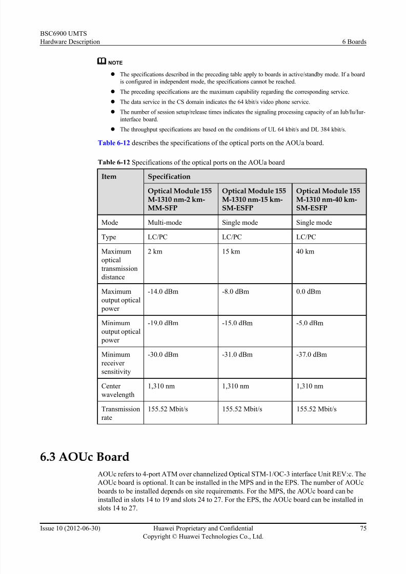
7/30/2019 BSC6900UMTS Hardware Description
http://slidepdf.com/reader/full/bsc6900umts-hardware-description 87/243
NOTE
l The specifications described in the preceding table apply to boards in active/standby mode. If a board
is configured in independent mode, the specifications cannot be reached.
l The preceding specifications are the maximum capability regarding the corresponding service.
l The data service in the CS domain indicates the 64 kbit/s video phone service.
l The number of session setup/release times indicates the signaling processing capacity of an Iub/Iu/Iur-
interface board.
l The throughput specifications are based on the conditions of UL 64 kbit/s and DL 384 kbit/s.
Table 6-12 describes the specifications of the optical ports on the AOUa board.
Table 6-12 Specifications of the optical ports on the AOUa board
Item Specification
Optical Module 155
M-1310 nm-2 km-MM-SFP
Optical Module 155
M-1310 nm-15 km-SM-ESFP
Optical Module 155
M-1310 nm-40 km-SM-ESFP
Mode Multi-mode Single mode Single mode
Type LC/PC LC/PC LC/PC
Maximum
optical
transmission
distance
2 km 15 km 40 km
Maximum
output optical power
-14.0 dBm -8.0 dBm 0.0 dBm
Minimum
output optical
power
-19.0 dBm -15.0 dBm -5.0 dBm
Minimum
receiver
sensitivity
-30.0 dBm -31.0 dBm -37.0 dBm
Center
wavelength
1,310 nm 1,310 nm 1,310 nm
Transmission
rate
155.52 Mbit/s 155.52 Mbit/s 155.52 Mbit/s
6.3 AOUc Board
AOUc refers to 4-port ATM over channelized Optical STM-1/OC-3 interface Unit REV:c. The
AOUc board is optional. It can be installed in the MPS and in the EPS. The number of AOUc
boards to be installed depends on site requirements. For the MPS, the AOUc board can be
installed in slots 14 to 19 and slots 24 to 27. For the EPS, the AOUc board can be installed inslots 14 to 27.
BSC6900 UMTS
Hardware Description 6 Boards
Issue 10 (2012-06-30) Huawei Proprietary and Confidential
Copyright © Huawei Technologies Co., Ltd.
75

7/30/2019 BSC6900UMTS Hardware Description
http://slidepdf.com/reader/full/bsc6900umts-hardware-description 88/243
NOTE
If the OMUa boards are not installed in slots 20 to 23 of the MPS, the AOUc boards can be installed in slots 20
to 23 of the MPS.
6.3.1 Functions of the AOUc BoardAs an optical interface board, the AOUc board supports ATM over channelized STM-1/OC-3
transmission.
The AOUc board performs the following functions:
l Provides four channels over the channelized STM-1/OC-3 optical ports
l Supports the IMA function
l Supports the extraction of line clock signals
l Supports the Iu, Iur, and Iub interfaces
6.3.2 Panel of the AOUc BoardThere are LEDs and ports on the panel of the AOUc board.
Figure 6-5 shows the panel of the AOUc board.
BSC6900 UMTS
Hardware Description 6 Boards
Issue 10 (2012-06-30) Huawei Proprietary and Confidential
Copyright © Huawei Technologies Co., Ltd.
76

7/30/2019 BSC6900UMTS Hardware Description
http://slidepdf.com/reader/full/bsc6900umts-hardware-description 89/243
Figure 6-5 Panel of the AOUc board
6.3.3 LEDs on the AOUc BoardThere are four types of LEDs on the AOUc board: RUN, ALM, ACT, and LOS.
Table 6-13 describes the LEDs on the AOUc board.
Table 6-13 LEDs on the AOUc board
LED Color
Status Description
RUN Gree
n
ON for 1s and OFF for 1s The board is functional.
BSC6900 UMTS
Hardware Description 6 Boards
Issue 10 (2012-06-30) Huawei Proprietary and Confidential
Copyright © Huawei Technologies Co., Ltd.
77

7/30/2019 BSC6900UMTS Hardware Description
http://slidepdf.com/reader/full/bsc6900umts-hardware-description 90/243
LED Color
Status Description
ON for 0.125s and OFF for
0.125s
The board is in loading state.
ON There is power supply, but the board
is faulty.
OFF There is no power supply, or the board
is faulty.
ALM Red OFF There is no alarm.
ON or blinking There is a fault alarm.
ACT Gree
n
ON The board is in active mode.
OFF The board is in standby mode.
LOS Gree
n
ON The STM-1 port does not receive
signals properly.
OFF The STM-1 port receives signals
properly.
6.3.4 Ports on the AOUc Board
There are four optical ports on the AOUc board.
Table 6-14 describes the ports on the AOUc board.
Table 6-14 Ports on the AOUc board
PortNumber
Port Function ConnectorType
Multiplexing E1 PortNumber
Multiplexing T1 PortNumber
0 RX Receiving
optical port
LC/PC 0 to 62 0 to 83
TX Transmittingoptical port
1 RX Receiving
optical port
LC/PC 63 to 125 84 to 167
TX Transmitting
optical port
2 RX Receiving
optical port
LC/PC 126 to 188 168 to 251
TX Transmitting
optical port
BSC6900 UMTS
Hardware Description 6 Boards
Issue 10 (2012-06-30) Huawei Proprietary and Confidential
Copyright © Huawei Technologies Co., Ltd.
78

7/30/2019 BSC6900UMTS Hardware Description
http://slidepdf.com/reader/full/bsc6900umts-hardware-description 91/243
PortNumber
Port Function ConnectorType
Multiplexing E1 PortNumber
Multiplexing T1 PortNumber
3 RX Receiving
optical port
LC/PC 189 to 251 252 to 335
TX Transmitting
optical port
6.3.5 Technical Specifications of the AOUc Board
The technical specifications of the AOUc board consist of hardware specifications and
specifications of optical ports and board processing capability. The hardware specifications
consist of the dimensions, power supply, power consumption, weight, operating temperature,and relative humidity.
Table 6-15 describes the hardware specifications of the AOUc board.
Table 6-15 Hardware specifications of the AOUc board
Item Specification
Dimensions 248 mm x 32.3mm x 395.4 mm
Power supply Two inputs of -48 V DC working in active/standby mode. The backplane
of the subrack is responsible for the power supply.
Power
consumption
75.19 W
Weight 1.50 kg
Operating
temperature
(long-term)
0°C to 45°C
Operating
temperature
(short-term)
-5°C to +55°C
Relative
humidity (long-
term)
5% to 85%
Relative
humidity (short-
term)
5% to 95%
Table 6-16 describes the specifications of the board processing capability.
BSC6900 UMTS
Hardware Description 6 Boards
Issue 10 (2012-06-30) Huawei Proprietary and Confidential
Copyright © Huawei Technologies Co., Ltd.
79

7/30/2019 BSC6900UMTS Hardware Description
http://slidepdf.com/reader/full/bsc6900umts-hardware-description 92/243
Table 6-16 Specifications of the board processing capability
Item Specification
Number of channel identifiers(CIDs) 79,000
Session setup/release times 3,000/s
Iub Number of NodeBs 500
Speech service in the CS
domain
18,000 Erlang
Data service in the CS domain 5,500 Erlang
Maximum payload throughput
(UL)
300 Mbit/s
Maximum payload throughput
(DL)
300 Mbit/s
Maximum payload throughput
(UL+DL)
600 Mbit/s
Iur Speech service in the CS
domain
18,000 Erlang
Data service in the CS domain 5,500 Erlang
Maximum payload throughput
(UL)
300 Mbit/s
Maximum payload throughput(DL)
300 Mbit/s
Maximum payload throughput
(UL+DL)
600 Mbit/s
Iu-CS Speech service in the CS
domain
18,000 Erlang
Data service in the CS domain 5,500 Erlang
Iu-PS Maximum payload throughput
(UL)
350 Mbit/s
Maximum payload throughput
(DL)
350 Mbit/s
Maximum payload throughput
(UL+DL)
700 Mbit/s
BSC6900 UMTS
Hardware Description 6 Boards
Issue 10 (2012-06-30) Huawei Proprietary and Confidential
Copyright © Huawei Technologies Co., Ltd.
80

7/30/2019 BSC6900UMTS Hardware Description
http://slidepdf.com/reader/full/bsc6900umts-hardware-description 93/243
NOTE
l The specifications described in the preceding table apply to boards in active/standby mode. If a board
is configured in independent mode, the specifications cannot be reached.
l The preceding specifications are the maximum capability regarding the corresponding service.
l The data service in the CS domain indicates the 64 kbit/s video phone service.
l The number of session setup/release times indicates the signaling processing capacity of an Iub/Iu/Iur-
interface board.
l The throughput specifications are based on the conditions of UL 64 kbit/s and DL 384 kbit/s.
Table 6-17 describes the specifications of the optical ports on the AOUc board.
Table 6-17 Specifications of the optical ports on the AOUc board
Item Specification
Optical Module 155M-1310 nm-2 km-MM-SFP
Optical Module 155M-1310 nm-15 km-SM-ESFP
Optical Module 155M-1310 nm-40 km-SM-ESFP
Mode Multi-mode Single mode Single mode
Type LC/PC LC/PC LC/PC
Maximum
optical
transmission
distance
2 km 15 km 40 km
Maximumoutput optical
power
-14.0 dBm -8.0 dBm 0.0 dBm
Minimum
output optical
power
-19.0 dBm -15.0 dBm -5.0 dBm
Minimum
receiver
sensitivity
-30.0 dBm -31.0 dBm -37.0 dBm
Center
wavelength
1,310 nm 1,310 nm 1,310 nm
Transmission
rate
155.52 Mbit/s 155.52 Mbit/s 155.52 Mbit/s
6.4 DPUb Board
DPUb refers to Data Processing Unit REV:b. The DPUb board is optional. For the MPS, two to
ten DPUb boards can be installed in slots 0 to 5, slots 8 to 11, slots 14 to 19, and slots 24 to 27.
For the EPS, two to twelve DPUb boards can be installed in slots 0 to 5, slots 8 to 27.
BSC6900 UMTS
Hardware Description 6 Boards
Issue 10 (2012-06-30) Huawei Proprietary and Confidential
Copyright © Huawei Technologies Co., Ltd.
81
7/30/2019 BSC6900UMTS Hardware Description
http://slidepdf.com/reader/full/bsc6900umts-hardware-description 94/243
NOTE
If the OMUa boards are not installed in slots 20 to 23 of the MPS, the DPUb boards can be installed in slots 20
to 23 of the MPS.
6.4.1 Functions of the DPUb BoardThe DPUb board processes and distributes the UMTS user-plane service data.
The DPUb board performs the following functions:
l Multiplexes and demultiplexes
l Processes frame protocols
l Selects and distributes data
l Performs the functions of the GTP-U, IUUP, PDCP, RLC, MAC, and FP protocols
l Performs encryption, decryption, and paging
l Processes internal communication protocols between the SPUa/SPUb board and the DPUb
board
l Processes the Multimedia Broadcast and Multicast Service (MBMS) at the RLC layer and
the MAC layer
6.4.2 Panel of the DPUb Board
There are only LEDs on the panel of the DPUb board.
Figure 6-6 shows the panel of the DPUb board.
BSC6900 UMTS
Hardware Description 6 Boards
Issue 10 (2012-06-30) Huawei Proprietary and Confidential
Copyright © Huawei Technologies Co., Ltd.
82

7/30/2019 BSC6900UMTS Hardware Description
http://slidepdf.com/reader/full/bsc6900umts-hardware-description 95/243
Figure 6-6 Panel of the DPUb board
6.4.3 LEDs on the DPUb Board
There are three LEDs on the DPUb board: RUN, ALM, and ACT.
Table 6-18 describes the LEDs on the DPUb board.
Table 6-18 LEDs on the DPUb board
LED Color Status Description
RUN Green ON for 1s and OFF for
1s
The board is functional.
ON for 0.125s and OFF
for 0.125s
The board is in loading state.
BSC6900 UMTS
Hardware Description 6 Boards
Issue 10 (2012-06-30) Huawei Proprietary and Confidential
Copyright © Huawei Technologies Co., Ltd.
83

7/30/2019 BSC6900UMTS Hardware Description
http://slidepdf.com/reader/full/bsc6900umts-hardware-description 96/243
LED Color Status Description
ON There is power supply, but the board
is faulty.
OFF There is no power supply, or the boardis faulty.
ALM Red OFF There is no alarm.
ON or blinking There is a fault alarm.
ACT Green ON The board is functional.
OFF The board is loading software or it is
abnormal.
6.4.4 Technical Specifications of the DPUb Board
The technical specifications of the DPUb board consist of the dimensions, power supply, power
consumption, weight, operating temperature, relative humidity, and processing capability.
Table 6-19 describes the technical specifications of the DPUb board.
Table 6-19 Technical specifications of the DPUb board
Item Specification
Dimensions 248 mm x 32.3mm x 395.4 mm
Power supply Two -48 V DC working in active/standby mode.
The backplane of the subrack is responsible for
the power supply.
Power consumption 60 W
Weight 1.26 kg
Operating temperature (long-term) 0°C to 45°C
Operating temperature (short-term) -5°C to +55°C
Relative humidity (long-term) 5% to 85%
Relative humidity (short-term) 5% to 95%
BSC6900 UMTS
Hardware Description 6 Boards
Issue 10 (2012-06-30) Huawei Proprietary and Confidential
Copyright © Huawei Technologies Co., Ltd.
84

7/30/2019 BSC6900UMTS Hardware Description
http://slidepdf.com/reader/full/bsc6900umts-hardware-description 97/243
Item Specification
Processing capability l Supporting the UL+DL data stream at 115
Mbit/s based on the conditions of UL 64
kbit/s and DL 384 kbit/s
l Supporting 1,800 Erlang for CS speech
service
l Supporting 900 Erlang for CS data service
l Supporting 150 cells
l Supporting a maximum of 3300 active
subscribers (DCH/HSDPA/FACH)
NOTE
l The preceding specifications are the maximum capability regarding the corresponding service.
l The data service in the CS domain indicates the 64 kbit/s video phone service.
6.5 DPUe Board
DPUe refers to Data Processing Unit REV:e. The DPUe board is optional. For the MPS, two to
ten DPUe boards can be installed in slots 0 to 5, slots 8 to 11, slots 14 to 19, and slots 24 to 27.
For the EPS, two to twelve DPUe boards can be installed in slots 0 to 5, slots 8 to 27.
NOTE
If the OMUa boards are not installed in slots 20 to 23 of the MPS, the DPUe boards can be installed in slots 20to 23 of the MPS.
6.5.1 Functions of the DPUe Board
The DPUe board processes and distributes the UMTS user-plane service data.
The DPUe board performs the following functions:
l Multiplexes and demultiplexes
l Processes frame protocols
l Selects and distributes data
l Performs the functions of the GTP-U, IUUP, PDCP, RLC, MAC, and FP protocols
l Performs encryption, decryption, and paging
l Processes internal communication protocols between the SPUa/SPUb board and the DPUe
board
l Processes the Multimedia Broadcast and Multicast Service (MBMS) at the RLC layer and
the MAC layer
6.5.2 Panel of the DPUe Board
There are only LEDs on the panel of the DPUe board.
Figure 6-7 shows the panel of the DPUe board.
BSC6900 UMTS
Hardware Description 6 Boards
Issue 10 (2012-06-30) Huawei Proprietary and Confidential
Copyright © Huawei Technologies Co., Ltd.
85

7/30/2019 BSC6900UMTS Hardware Description
http://slidepdf.com/reader/full/bsc6900umts-hardware-description 98/243
Figure 6-7 Panel of the DPUe board
6.5.3 LEDs on the DPUe Board
There are three LEDs on the DPUe board: RUN, ALM, and ACT.
Table 6-20 describes the LEDs on the DPUe board.
Table 6-20 LEDs on the DPUe board
LED Color Status Description
RUN Green ON for 1s and OFF for
1s
The board is functional.
ON for 0.125s and OFF
for 0.125s
The board is in loading state.
BSC6900 UMTS
Hardware Description 6 Boards
Issue 10 (2012-06-30) Huawei Proprietary and Confidential
Copyright © Huawei Technologies Co., Ltd.
86

7/30/2019 BSC6900UMTS Hardware Description
http://slidepdf.com/reader/full/bsc6900umts-hardware-description 99/243
LED Color Status Description
ON There is power supply, but the board
is faulty.
OFF There is no power supply, or the boardis faulty.
ALM Red OFF There is no alarm.
ON or blinking There is a fault alarm.
ACT Green ON The board is functional.
OFF The board is loading software or it is
abnormal.
6.5.4 Technical Specifications of the DPUe Board
The technical specifications of the DPUe board consist of the dimensions, power supply, power
consumption, weight, operating temperature, relative humidity, and processing capability.
Table 6-21 describes the technical specifications of the DPUe board.
Table 6-21 Technical specifications of the DPUe board
Item Specification
Dimensions 248 mm x 32.3mm x 395.4 mm
Power supply Two -48 V DC working in active/standby mode.
The backplane of the subrack is responsible for
the power supply.
Power consumption 62.32 W
Weight 1.20 kg
Operating temperature (long-term) 0°C to 45°C
Operating temperature (short-term) -5°C to +55°C
Relative humidity (long-term) 5% to 85%
Relative humidity (short-term) 5% to 95%
BSC6900 UMTS
Hardware Description 6 Boards
Issue 10 (2012-06-30) Huawei Proprietary and Confidential
Copyright © Huawei Technologies Co., Ltd.
87

7/30/2019 BSC6900UMTS Hardware Description
http://slidepdf.com/reader/full/bsc6900umts-hardware-description 100/243
Item Specification
Processing capability l Supporting the UL+DL data stream at 335
Mbit/s based on the conditions of UL 64
kbit/s and DL 384 kbit/s;Supporting the UL
+DL data stream at 800 Mbit/s based on the
conditions of UL 64 kbit/s and DL 384 kbit/
s if the capacity license is configured
l Supporting 3,350 Erlang for CS speech
service
l Supporting 1,675 Erlang for CS data service
l Supporting 300 cells
l Supporting a maximum of 5880 active
subscribers (DCH/HSDPA/FACH)
6.6 FG2a Board
FG2a refers to 8-port FE or 2-port electronic GE interface unit REV:a. The FG2a board is
optional. It can be installed either in the MPS or in the EPS. The number of FG2a boards to be
installed depends on site requirements. For the MPS, the FG2a board can be installed in slots
14 to 19 and slots 24 to 27. For the EPS, the FG2a board can be installed in slots 14 to 27.
NOTE
If the OMUa boards are not installed in slots 20 to 23 of the MPS, the FG2a boards can be installed in slots 20
to 23 of the MPS.
6.6.1 Functions of the FG2a Board
As an interface board, the FG2a board provides IP over Ethernet.
The FG2a board performs the following functions:
l Provides eight channels over FE ports or two channels over GE ports
l Provides the routing-based backup and load sharing
l Provides the link aggregation function at the MAC layer
l Supports the Iu, Iur, and Iub interfaces
6.6.2 Panel of the FG2a Board
There are LEDs and ports on the panel of the FG2a board.
Figure 6-8 shows the panel of the FG2a board.
BSC6900 UMTS
Hardware Description 6 Boards
Issue 10 (2012-06-30) Huawei Proprietary and Confidential
Copyright © Huawei Technologies Co., Ltd.
88

7/30/2019 BSC6900UMTS Hardware Description
http://slidepdf.com/reader/full/bsc6900umts-hardware-description 101/243
Figure 6-8 Panel of the FG2a board
6.6.3 LEDs on the FG2a BoardAmong all the LEDs on the FG2a board, RUN, ALM, and ACT indicate the status of the FG2a
board, and other LEDs indicate the status of Ethernet ports. There are two LEDs at each Ethernet
port: LINK and ACT.
Table 6-22 describes the LEDs on the FG2a board.
Table 6-22 LEDs on the FG2a board
LED Color Status Description
RUN Green ON for 1s and OFF for 1s The board is functional.
BSC6900 UMTS
Hardware Description 6 Boards
Issue 10 (2012-06-30) Huawei Proprietary and Confidential
Copyright © Huawei Technologies Co., Ltd.
89
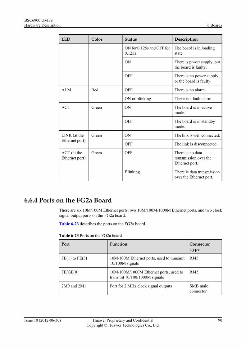
7/30/2019 BSC6900UMTS Hardware Description
http://slidepdf.com/reader/full/bsc6900umts-hardware-description 102/243
LED Color Status Description
ON for 0.125s and OFF for
0.125s
The board is in loading
state.
ON There is power supply, butthe board is faulty.
OFF There is no power supply,
or the board is faulty.
ALM Red OFF There is no alarm.
ON or blinking There is a fault alarm.
ACT Green ON The board is in active
mode.
OFF The board is in standbymode.
LINK (at the
Ethernet port)
Green ON The link is well connected.
OFF The link is disconnected.
ACT (at the
Ethernet port)
Green OFF There is no data
transmission over the
Ethernet port.
Blinking There is data transmission
over the Ethernet port.
6.6.4 Ports on the FG2a Board
There are six 10M/100M Ethernet ports, two 10M/100M/1000M Ethernet ports, and two clock
signal output ports on the FG2a board.
Table 6-23 describes the ports on the FG2a board.
Table 6-23 Ports on the FG2a board
Port Function ConnectorType
FE(1) to FE(3) 10M/100M Ethernet ports, used to transmit
10/100M signals
RJ45
FE/GE(0) 10M/100M/1000M Ethernet ports, used to
transmit 10/100/1000M signals
RJ45
2M0 and 2M1 Port for 2 MHz clock signal outputs SMB male
connector
BSC6900 UMTS
Hardware Description 6 Boards
Issue 10 (2012-06-30) Huawei Proprietary and Confidential
Copyright © Huawei Technologies Co., Ltd.
90

7/30/2019 BSC6900UMTS Hardware Description
http://slidepdf.com/reader/full/bsc6900umts-hardware-description 103/243
6.6.5 Technical Specifications of the FG2a Board
The technical specifications of the FG2a board consist of hardware specifications and
specifications of the board processing capability. The hardware specifications consist of the
dimensions, power supply, power consumption, weight, operating temperature, and relativehumidity.
Table 6-24 describes the hardware specifications of the FG2a board.
Table 6-24 Hardware specifications of the FG2a board
Item Specification
Dimensions 248 mm x 32.3mm x 395.4 mm
Power supply Two -48 V DC working in active/standby mode.
The backplane of the subrack is responsible for
the power supply.
Power consumption 38.48 W
Weight 1.36 kg
Operating temperature (long-term) 0°C to 45°C
Operating temperature (short-term) -5°C to +55°C
Relative humidity (long-term) 5% to 85%
Relative humidity (short-term) 5% to 95%
Table 6-25 describes the specifications of the board processing capability.
Table 6-25 Specifications of the board processing capability
Item Specification
Number of UDP (User Datagram Protocol) ports 23,000
Session setup/release times 500/s
Iub Number of NodeBs 300
Speech service in the CS domain 6,000 Erlang
Data service in the CS domain 6,000 Erlang
Maximum payload throughput (UL) 840 Mbit/s
Maximum payload throughput (DL) 840 Mbit/s
Maximum payload throughput (UL
+DL)
840 Mbit/s
Iur Speech service in the CS domain 6,000 Erlang
BSC6900 UMTS
Hardware Description 6 Boards
Issue 10 (2012-06-30) Huawei Proprietary and Confidential
Copyright © Huawei Technologies Co., Ltd.
91

7/30/2019 BSC6900UMTS Hardware Description
http://slidepdf.com/reader/full/bsc6900umts-hardware-description 104/243
Item Specification
Data service in the CS domain 6,000 Erlang
Maximum payload throughput (UL) 840 Mbit/s
Maximum payload throughput (DL) 840 Mbit/s
Maximum payload throughput (UL
+DL)
840 Mbit/s
Iu-CS Speech service in the CS domain 6,000 Erlang
Data service in the CS domain 3,000 Erlang
Iu-PS Maximum payload throughput (UL) 840 Mbit/s
Maximum payload throughput (DL) 840 Mbit/s
Maximum payload throughput (UL+DL)
840 Mbit/s
NOTE
l The specifications described in the preceding table apply to boards in active/standby mode. If a board
is configured in independent mode, the specifications cannot be reached.
l The preceding specifications are the maximum capability regarding the corresponding service.
l The data service in the CS domain indicates the 64 kbit/s video phone service.
l The number of session setup/release times indicates the signaling processing capacity of an Iub/Iu/Iur-interface board.
l The throughput specifications are based on the conditions of UL 64 kbit/s and DL 384 kbit/s.
6.7 FG2c Board
FG2c refers to 12-port FE or 4-port electronic GE interface unit REV:c. The FG2c board is
optional. It can be installed in the MPS and in the EPS. The number of FG2c boards to be installed
depends on site requirements. For the MPS, the FG2c board can be installed in slots 14 to 19.
For the EPS, the FG2c board can be installed in slots 14 to 23.
NOTE
If the OMUa boards are not installed in slots 20 to 23 of the MPS, the FG2c boards can be installed in slots 20
to 23 of the MPS.
6.7.1 Functions of the FG2c Board
As an interface board, the FG2c board supports IP over Ethernet transmission.
The FG2c board performs the following functions:
l Provides 12 channels over FE ports or four channels over GE ports
l Provides the link aggregation function at the MAC layer
l Provides the routing-based backup and load sharing
BSC6900 UMTS
Hardware Description 6 Boards
Issue 10 (2012-06-30) Huawei Proprietary and Confidential
Copyright © Huawei Technologies Co., Ltd.
92

7/30/2019 BSC6900UMTS Hardware Description
http://slidepdf.com/reader/full/bsc6900umts-hardware-description 105/243
l Supports the transmission of data over all its Ethernet ports on the basis of the synchronized
clock signals
l Supports the Iu, Iur, and Iub interfaces
CAUTION
The FG2c board has the following restrictions:
l The FG2c board does not work in 10 Mbit/s or 100 Mbit/s half-duplex mode
l If GE ports are used, the ports must be set to the automatic negotiation mode on both the
local end and the peer end.
l If FE ports are used, the ports must be set to the same negotiation mode on both the local end
and the peer end.
6.7.2 Panel of the FG2c Board
There are LEDs and ports on the panel of the FG2c board.
Figure 6-9 shows the panel of the FG2c board.
BSC6900 UMTS
Hardware Description 6 Boards
Issue 10 (2012-06-30) Huawei Proprietary and Confidential
Copyright © Huawei Technologies Co., Ltd.
93

7/30/2019 BSC6900UMTS Hardware Description
http://slidepdf.com/reader/full/bsc6900umts-hardware-description 106/243
Figure 6-9 Panel of the FG2c board
6.7.3 LEDs on the FG2c BoardAmong all the LEDs on the FG2c board, RUN, ALM, and ACT indicate the status of the FG2c
board, and other LEDs indicate the status of Ethernet ports. There are two LEDs at each Ethernet
port: LINK and ACT.
Table 6-26 describes the LEDs on the FG2c board.
Table 6-26 LEDs on the FG2c board
LED Color Status Description
RUN Green ON for 1s and OFF for 1s The board is functional.
BSC6900 UMTS
Hardware Description 6 Boards
Issue 10 (2012-06-30) Huawei Proprietary and Confidential
Copyright © Huawei Technologies Co., Ltd.
94

7/30/2019 BSC6900UMTS Hardware Description
http://slidepdf.com/reader/full/bsc6900umts-hardware-description 107/243
LED Color Status Description
ON for 0.125s and OFF for
0.125s
The board is in loading
state.
ON There is power supply, butthe board is faulty.
OFF There is no power supply,
or the board is faulty.
ALM Red OFF There is no alarm.
ON or blinking There is a fault alarm.
ACT Green ON The board is in active
mode.
OFF The board is in standbymode.
LINK (at the
Ethernet port)
Green ON The link is well connected.
OFF The link is disconnected.
ACT (at the
Ethernet port)
Orange OFF There is no data
transmission over the
Ethernet port.
Blinking There is data transmission
over the Ethernet port.
6.7.4 Ports on the FG2c Board
There are four 100/1000BASE-T ports and eight 100BASE-T ports on the FG2c board.
Table 6-27 describes the ports on the FG2c board.
Table 6-27 Ports on the FG2c board
Port Function Connector
Type
100BASE-T 100M Ethernet ports, used to transmit 100M
signals
RJ45
100/1000BASE-T 100M/1000M Ethernet ports, used to
transmit 100/1000M signals
RJ45
6.7.5 Technical Specifications of the FG2c Board
The technical specifications of the FG2c board consist of hardware specifications andspecifications of the board processing capability. The hardware specifications consist of the
BSC6900 UMTS
Hardware Description 6 Boards
Issue 10 (2012-06-30) Huawei Proprietary and Confidential
Copyright © Huawei Technologies Co., Ltd.
95

7/30/2019 BSC6900UMTS Hardware Description
http://slidepdf.com/reader/full/bsc6900umts-hardware-description 108/243
dimensions, power supply, power consumption, weight, operating temperature, and relative
humidity.
Table 6-28 describes the hardware specifications of the FG2c board.
Table 6-28 Hardware specifications of the FG2c board
Item Specification
Dimensions 248 mm x 32.3mm x 395.4 mm
Power supply Two inputs of -48 V DC working in active/
standby mode. The backplane of the subrack is
responsible for the power supply.
Power consumption 85.4 W
Weight 1.50 kg
Operating temperature (long-term) 0°C to 45°C
Operating temperature (short-term) -5°C to +55°C
Relative humidity (long-term) 5% to 85%
Relative humidity (short-term) 5% to 95%
Table 6-29 describes the specifications of the board processing capability.
Table 6-29 Specifications of the board processing capability
Item Specification
Number of UDP (User Datagram Protocol) ports 79,000
Session setup/release times 3,000/s
Iub Number of NodeBs 500
Speech service in the CS domain 18,000 Erlang
Data service in the CS domain 18,000 Erlang
Maximum payload throughput (UL) 1,300 Mbit/s
Maximum payload throughput (DL) 1,300 Mbit/s
Maximum payload throughput (UL
+DL)
2,600 Mbit/s
Iur Speech service in the CS domain 18,000 Erlang
Data service in the CS domain 18,000 Erlang
Maximum payload throughput (UL) 1,300 Mbit/s
Maximum payload throughput (DL) 1,300 Mbit/s
BSC6900 UMTS
Hardware Description 6 Boards
Issue 10 (2012-06-30) Huawei Proprietary and Confidential
Copyright © Huawei Technologies Co., Ltd.
96

7/30/2019 BSC6900UMTS Hardware Description
http://slidepdf.com/reader/full/bsc6900umts-hardware-description 109/243
Item Specification
Maximum payload throughput (UL
+DL)
2,600 Mbit/s
Iu-CS Speech service in the CS domain 18,000 Erlang
Data service in the CS domain 9,000 Erlang
Iu-PS Maximum payload throughput (UL) 1,600 Mbit/s
Maximum payload throughput (DL) 1,600 Mbit/s
Maximum payload throughput (UL
+DL)
3,200 Mbit/s
NOTE
l The specifications described in the preceding table apply to boards in active/standby mode. If a board
is configured in independent mode, the specifications cannot be reached.
l The preceding specifications are the maximum capability regarding the corresponding service.
l The data service in the CS domain indicates the 64 kbit/s video phone service.
l The number of session setup/release times indicates the signaling processing capacity of an Iub/Iu/Iur-
interface board.
l The throughput specifications are based on the conditions of UL 64 kbit/s and DL 384 kbit/s.
6.8 GCUa/GCGa BoardGCUa refers to General Clock Unit REV:a. GCGa refers to General Clock Unit with GPS REV:a.
The GCUa/GCGa board is mandatory. Two GCUa/GCGa boards must be installed in slots 12
and 13 in the MPS.
6.8.1 Functions of the GCUa/GCGa Board
The GCUa/GCGa board performs the clock function.
The GCUa/GCGa board performs the following functions:
l Extracts timing signals from the external synchronization timing port and from the
synchronization line signals, processes the timing signals, and provides the timing signals
and the reference clock for the entire system
l Performs the fast pull-in and holdover functions on the system clock
l Generates RFN signals for the system
l Supports active/standby switchover. The standby GCUa/GCGa board traces the clock
phase of the active GCUa/GCGa board. This ensures the smooth output of the clock phase
in the case of active/standby switchover.
l Receives and processes the clock signals and the positioning information from the GPS
card. (Only the GCGa board supports this function.)
6.8.2 Panel of the GCUa/GCGa Board
There are LEDs and ports on the panel of the GCUa/GCGa board.
BSC6900 UMTS
Hardware Description 6 Boards
Issue 10 (2012-06-30) Huawei Proprietary and Confidential
Copyright © Huawei Technologies Co., Ltd.
97

7/30/2019 BSC6900UMTS Hardware Description
http://slidepdf.com/reader/full/bsc6900umts-hardware-description 110/243
Figure 6-10 shows the panel of the GCUa/GCGa board.
Figure 6-10 Panel of the GCUa/GCGa board
6.8.3 LEDs on the GCUa/GCGa Board
There are three LEDs on the panel of the GCUa/GCGa board: RUN, ALM, and ACT.
Table 6-30 describes the LEDs on the GCUa/GCGa board.
BSC6900 UMTS
Hardware Description 6 Boards
Issue 10 (2012-06-30) Huawei Proprietary and Confidential
Copyright © Huawei Technologies Co., Ltd.
98

7/30/2019 BSC6900UMTS Hardware Description
http://slidepdf.com/reader/full/bsc6900umts-hardware-description 111/243
Table 6-30 LEDs on the GCUa/GCGa board
LED Color Status Description
RUN Green ON for 1s and OFF for
1s
The board is functional.
ON for 0.125s and OFF
for 0.125s
The board is in loading state.
ON There is power supply, but the
board is faulty.
OFF There is no power supply, or the
board is faulty.
ALM Red OFF There is no alarm.
ON or blinking There is a fault alarm.
ACT Green ON The board is in active mode.
OFF The board is in standby mode.
6.8.4 Ports on the GCUa/GCGa Board
There are 17 ports on the GCUa/GCGa board.
Table 6-31 describes the ports on the GCUa/GCGa board.
Table 6-31 Ports on the GCUa/GCGa board
Port Function Connector Type
ANT Port for the GPS antenna. This port on the GCGa
board is used to receive the timing signals and
positioning information from the GPS satellite. This
port is not used on the GCUa board.
SMA male
connector
CLKOUT0 to
CLKOUT9
Ports for providing synchronization clock signals.
The ten ports are used to provide 8 kHz clock signals
and 1PPS clock signals.
RJ45
COM0 Reserved.This interface receives only clock signals
and discards other signals.
RJ45
COM1 Port for RS422-level 8 kHz clock signals RJ45
TESTOUT Output port for clock signals. The clock signals are
used for testing.
SMB male
connector
TESTIN Input port for testing external clock signals SMB male
connector
BSC6900 UMTS
Hardware Description 6 Boards
Issue 10 (2012-06-30) Huawei Proprietary and Confidential
Copyright © Huawei Technologies Co., Ltd.
99
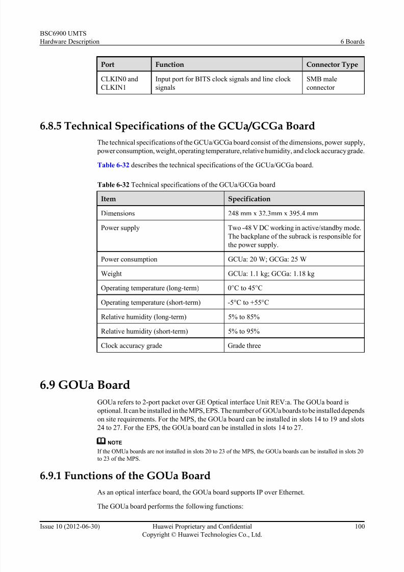
7/30/2019 BSC6900UMTS Hardware Description
http://slidepdf.com/reader/full/bsc6900umts-hardware-description 112/243
Port Function Connector Type
CLKIN0 and
CLKIN1
Input port for BITS clock signals and line clock
signals
SMB male
connector
6.8.5 Technical Specifications of the GCUa/GCGa Board
The technical specifications of the GCUa/GCGa board consist of the dimensions, power supply,
power consumption, weight, operating temperature, relative humidity, and clock accuracy grade.
Table 6-32 describes the technical specifications of the GCUa/GCGa board.
Table 6-32 Technical specifications of the GCUa/GCGa board
Item Specification
Dimensions 248 mm x 32.3mm x 395.4 mm
Power supply Two -48 V DC working in active/standby mode.
The backplane of the subrack is responsible for
the power supply.
Power consumption GCUa: 20 W; GCGa: 25 W
Weight GCUa: 1.1 kg; GCGa: 1.18 kg
Operating temperature (long-term) 0°C to 45°C
Operating temperature (short-term) -5°C to +55°C
Relative humidity (long-term) 5% to 85%
Relative humidity (short-term) 5% to 95%
Clock accuracy grade Grade three
6.9 GOUa Board
GOUa refers to 2-port packet over GE Optical interface Unit REV:a. The GOUa board isoptional. It can be installed in the MPS, EPS. The number of GOUa boards to be installed depends
on site requirements. For the MPS, the GOUa board can be installed in slots 14 to 19 and slots
24 to 27. For the EPS, the GOUa board can be installed in slots 14 to 27.
NOTE
If the OMUa boards are not installed in slots 20 to 23 of the MPS, the GOUa boards can be installed in slots 20
to 23 of the MPS.
6.9.1 Functions of the GOUa Board
As an optical interface board, the GOUa board supports IP over Ethernet.
The GOUa board performs the following functions:
BSC6900 UMTS
Hardware Description 6 Boards
Issue 10 (2012-06-30) Huawei Proprietary and Confidential
Copyright © Huawei Technologies Co., Ltd.
100

7/30/2019 BSC6900UMTS Hardware Description
http://slidepdf.com/reader/full/bsc6900umts-hardware-description 113/243
l Provides two channels over GE optical ports, which are used for IP transmission
l Provides the routing-based backup and load sharing
l Supports the Iu, Iur, and Iub interfaces
6.9.2 Panel of the GOUa BoardThere are LEDs and ports on the panel of the GOUa board.
Figure 6-11 shows the panel of the GOUa board.
Figure 6-11 Panel of the GOUa board
6.9.3 LEDs on the GOUa Board
There are thr ee LEDs on the GOUa board: RUN, ALM, and ACT.
Table 6-33 describes the LEDs on the GOUa board.
BSC6900 UMTS
Hardware Description 6 Boards
Issue 10 (2012-06-30) Huawei Proprietary and Confidential
Copyright © Huawei Technologies Co., Ltd.
101

7/30/2019 BSC6900UMTS Hardware Description
http://slidepdf.com/reader/full/bsc6900umts-hardware-description 114/243
Table 6-33 LEDs on the GOUa board
LED Color Status Description
RUN Green ON for 1s and OFF for 1s The board is functional.
ON for 0.125s and OFF for
0.125s
The board is in loading
state.
ON There is power supply, but
the board is faulty.
OFF There is no power supply,
or the board is faulty.
ALM Red OFF There is no alarm.
ON or blinking There is a fault alarm.
ACT Green ON The board is in activemode.
OFF The board is in standby
mode.
6.9.4 Ports on the GOUa Board
There are two optical ports and two clock signal output ports on the GOUa board.
Table 6-34 describes the ports on the GOUa board.
Table 6-34 Ports on the GOUa board
Port Function Connector Type
RX Optical port, used to transmit and receive optical
signals. TX refers to the transmitting optical port,
and RX refers to the receiving optical port.
LC/PC
TX
2M0 and
2M1
Port for 2 MHz clock signal outputs SMB male connector
6.9.5 Technical Specifications of the GOUa Board
The technical specifications of the GOUa board consist of hardware specifications and
specifications of the optical ports and board processing capability. The hardware specifications
consist of the dimensions, power supply, power consumption, weight, operating temperature,
and relative humidity.
Table 6-35 describes the hardware specifications of the GOUa board.
BSC6900 UMTS
Hardware Description 6 Boards
Issue 10 (2012-06-30) Huawei Proprietary and Confidential
Copyright © Huawei Technologies Co., Ltd.
102

7/30/2019 BSC6900UMTS Hardware Description
http://slidepdf.com/reader/full/bsc6900umts-hardware-description 115/243
Table 6-35 Hardware specifications of the GOUa board
Item Specification
Dimensions 248 mm x 32.3mm x 395.4 mm
Power supply Two -48 V DC working in active/standby mode. The backplane
of the subrack is responsible for the power supply.
Power consumption 37.30 W
Weight 1.20 kg
Operating temperature
(long-term)
0°C to 45°C
Operating temperature
(short-term)
-5°C to +55°C
Relative humidity (long-term)
5% to 85%
Relative humidity
(short-term)
5% to 95%
Table 6-36 describes the specifications of the board processing capability.
Table 6-36 Specifications of the board processing capability
Item Specification
Number of UDP (User Datagram Protocol) ports 23,000
Session setup/release times 500/s
Iub Number of NodeBs 300
Speech service in the CS domain 6,000 Erlang
Data service in the CS domain 6,000 Erlang
Maximum payload throughput (UL) 840 Mbit/s
Maximum payload throughput (DL) 840 Mbit/s
Maximum payload throughput (UL
+DL)
840 Mbit/s
Iur Speech service in the CS domain 6,000 Erlang
Data service in the CS domain 6,000 Erlang
Maximum payload throughput (UL) 840 Mbit/s
Maximum payload throughput (DL) 840 Mbit/s
BSC6900 UMTS
Hardware Description 6 Boards
Issue 10 (2012-06-30) Huawei Proprietary and Confidential
Copyright © Huawei Technologies Co., Ltd.
103
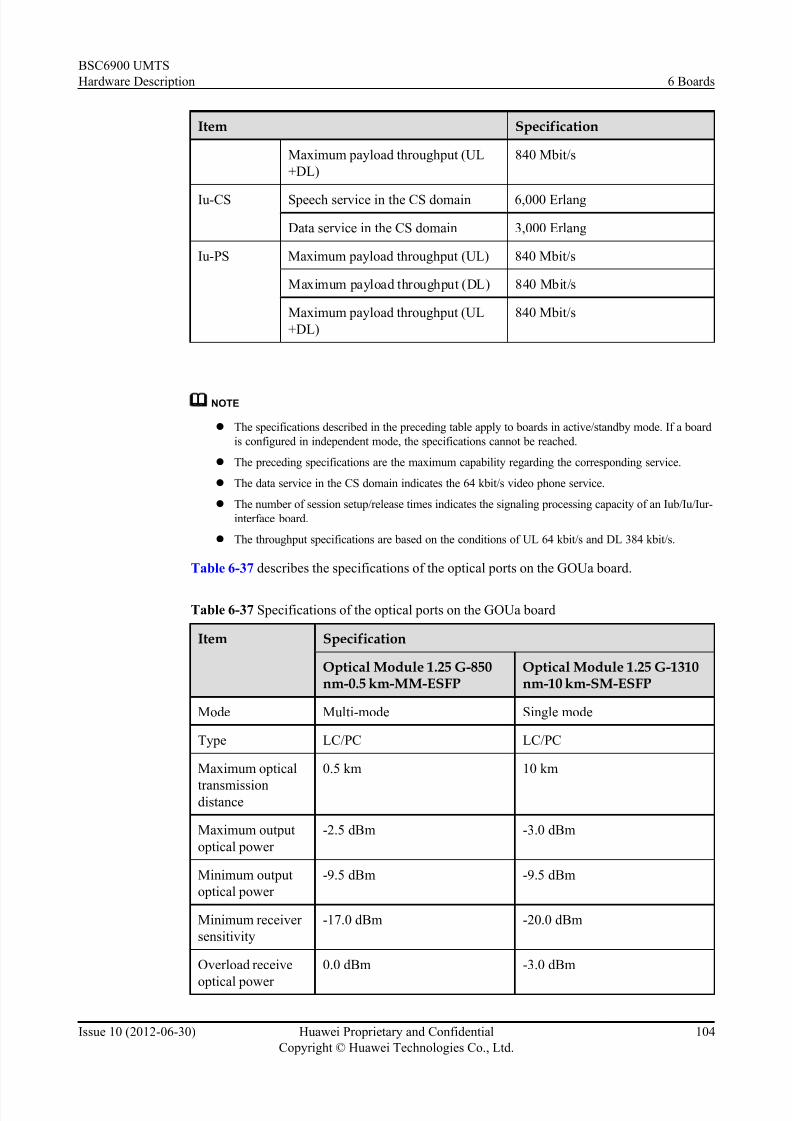
7/30/2019 BSC6900UMTS Hardware Description
http://slidepdf.com/reader/full/bsc6900umts-hardware-description 116/243
Item Specification
Maximum payload throughput (UL
+DL)
840 Mbit/s
Iu-CS Speech service in the CS domain 6,000 Erlang
Data service in the CS domain 3,000 Erlang
Iu-PS Maximum payload throughput (UL) 840 Mbit/s
Maximum payload throughput (DL) 840 Mbit/s
Maximum payload throughput (UL
+DL)
840 Mbit/s
NOTE
l The specifications described in the preceding table apply to boards in active/standby mode. If a board
is configured in independent mode, the specifications cannot be reached.
l The preceding specifications are the maximum capability regarding the corresponding service.
l The data service in the CS domain indicates the 64 kbit/s video phone service.
l The number of session setup/release times indicates the signaling processing capacity of an Iub/Iu/Iur-
interface board.
l The throughput specifications are based on the conditions of UL 64 kbit/s and DL 384 kbit/s.
Table 6-37 describes the specifications of the optical ports on the GOUa board.
Table 6-37 Specifications of the optical ports on the GOUa board
Item Specification
Optical Module 1.25 G-850nm-0.5 km-MM-ESFP
Optical Module 1.25 G-1310nm-10 km-SM-ESFP
Mode Multi-mode Single mode
Type LC/PC LC/PC
Maximum optical
transmissiondistance
0.5 km 10 km
Maximum output
optical power
-2.5 dBm -3.0 dBm
Minimum output
optical power
-9.5 dBm -9.5 dBm
Minimum receiver
sensitivity
-17.0 dBm -20.0 dBm
Overload receive
optical power
0.0 dBm -3.0 dBm
BSC6900 UMTS
Hardware Description 6 Boards
Issue 10 (2012-06-30) Huawei Proprietary and Confidential
Copyright © Huawei Technologies Co., Ltd.
104

7/30/2019 BSC6900UMTS Hardware Description
http://slidepdf.com/reader/full/bsc6900umts-hardware-description 117/243
Item Specification
Optical Module 1.25 G-850nm-0.5 km-MM-ESFP
Optical Module 1.25 G-1310nm-10 km-SM-ESFP
Center wavelength 850 nm 1,310 nm
Transmission rate 1.25 Gbit/s 1.25 Gbit/s
6.10 GOUc Board
GOUc refers to 4-port packet over GE Optical interface Unit REV:c. The GOUc board is
optional. It can be installed in the MPS and in the EPS. The number of GOUc boards to be
installed depends on site requirements. For the MPS, the GOUc board can be installed in slots
14 to 19. For the EPS, the GOUc board can be installed in slots 14 to 23.
NOTE
If the OMUa boards are not installed in slots 20 to 23 of the MPS, the GOUc boards can be installed in slots 20
to 23 of the MPS.
6.10.1 Functions of the GOUc Board
As an optical interface board, the GOUc board supports IP over Ethernet transmission.
The GOUc board performs the following functions:
l Provides four channels over GE ports
l Provides the routing-based backup and load sharing
l Supports the Iu, Iur, and Iub interfaces
NOTE
The GOUc board does not support the 10 Mbit/s or 100 Mbit/s half duplex mode.
6.10.2 Panel of the GOUc Board
There are LEDs and ports on the panel of the GOUc board.
Figure 6-12 shows the panel of the GOUc board.
BSC6900 UMTS
Hardware Description 6 Boards
Issue 10 (2012-06-30) Huawei Proprietary and Confidential
Copyright © Huawei Technologies Co., Ltd.
105

7/30/2019 BSC6900UMTS Hardware Description
http://slidepdf.com/reader/full/bsc6900umts-hardware-description 118/243
Figure 6-12 Panel of the GOUc board
6.10.3 LEDs on the GOUc BoardThere are five types of LEDs on the GOUc board: RUN, ALM, ACT, LINK (optical port LED),
and ACT (optical port LED).
Table 6-38 describes the LEDs on the GOUc board.
Table 6-38 LEDs on the GOUc board
LED Color Status Description
RUN Green ON for 1s and OFF for 1s The board is functional.
BSC6900 UMTS
Hardware Description 6 Boards
Issue 10 (2012-06-30) Huawei Proprietary and Confidential
Copyright © Huawei Technologies Co., Ltd.
106
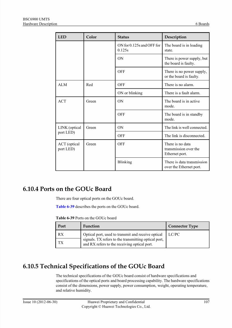
7/30/2019 BSC6900UMTS Hardware Description
http://slidepdf.com/reader/full/bsc6900umts-hardware-description 119/243
LED Color Status Description
ON for 0.125s and OFF for
0.125s
The board is in loading
state.
ON There is power supply, butthe board is faulty.
OFF There is no power supply,
or the board is faulty.
ALM Red OFF There is no alarm.
ON or blinking There is a fault alarm.
ACT Green ON The board is in active
mode.
OFF The board is in standbymode.
LINK (optical
port LED)
Green ON The link is well connected.
OFF The link is disconnected.
ACT (optical
port LED)
Green OFF There is no data
transmission over the
Ethernet port.
Blinking There is data transmission
over the Ethernet port.
6.10.4 Ports on the GOUc Board
There are four optical ports on the GOUc board.
Table 6-39 describes the ports on the GOUc board.
Table 6-39 Ports on the GOUc board
Port Function Connector Type
RX Optical port, used to transmit and receive optical
signals. TX refers to the transmitting optical port,
and RX refers to the receiving optical port.
LC/PC
TX
6.10.5 Technical Specifications of the GOUc Board
The technical specifications of the GOUc board consist of hardware specifications and
specifications of the optical ports and board processing capability. The hardware specifications
consist of the dimensions, power supply, power consumption, weight, operating temperature,and relative humidity.
BSC6900 UMTS
Hardware Description 6 Boards
Issue 10 (2012-06-30) Huawei Proprietary and Confidential
Copyright © Huawei Technologies Co., Ltd.
107

7/30/2019 BSC6900UMTS Hardware Description
http://slidepdf.com/reader/full/bsc6900umts-hardware-description 120/243
Table 6-40 describes the hardware specifications of the GOUc board.
Table 6-40 Hardware specifications of the GOUc board
Item Specification
Dimensions 248 mm x 32.3mm x 395.4 mm
Power supply Two inputs of -48 V DC working in active/standby mode. The
backplane of the subrack is responsible for the power supply.
Power consumption 65.90 W
Weight 1.40 kg
Operating temperature
(long-term)
0°C to 45°C
Operating temperature(short-term)
-5°C to +55°C
Relative humidity (long-
term)
5% to 85%
Relative humidity
(short-term)
5% to 95%
Table 6-41 describes the specifications of the board processing capability.
Table 6-41 Specifications of the board processing capability
Item Specification
Number of UDP (User Datagram Protocol) ports 79,000
Session setup/release times 3,000/s
Iub Number of NodeBs 500
Speech service in the CS domain 18,000 Erlang
Data service in the CS domain 18,000 Erlang
Maximum payload throughput (UL) 1,300 Mbit/s
Maximum payload throughput (DL) 1,300 Mbit/s
Maximum payload throughput (UL
+DL)
2,600 Mbit/s
Iur Speech service in the CS domain 18,000 Erlang
Data service in the CS domain 18,000 Erlang
Maximum payload throughput (UL) 1,300 Mbit/s
BSC6900 UMTS
Hardware Description 6 Boards
Issue 10 (2012-06-30) Huawei Proprietary and Confidential
Copyright © Huawei Technologies Co., Ltd.
108

7/30/2019 BSC6900UMTS Hardware Description
http://slidepdf.com/reader/full/bsc6900umts-hardware-description 121/243
Item Specification
Maximum payload throughput (DL) 1,300 Mbit/s
Maximum payload throughput (UL
+DL)
2,600 Mbit/s
Iu-CS Speech service in the CS domain 18,000 Erlang
Data service in the CS domain 9,000 Erlang
Iu-PS Maximum payload throughput (UL) 1,600 Mbit/s
Maximum payload throughput (DL) 1,600 Mbit/s
Maximum payload throughput (UL
+DL)
3,200 Mbit/s
NOTE
l The specifications described in the preceding table apply to boards in active/standby mode. If a board
is configured in independent mode, the specifications cannot be reached.
l The preceding specifications are the maximum capability regarding the corresponding service.
l The data service in the CS domain indicates the 64 kbit/s video phone service.
l The number of session setup/release times indicates the signaling processing capacity of an Iub/Iu/Iur-
interface board.
l The throughput specifications are based on the conditions of UL 64 kbit/s and DL 384 kbit/s.
Table 6-42 describes the specifications of the optical ports on the GOUc board.
Table 6-42 Specifications of the optical ports on the GOUc board
Item Specification
Optical Module 1.25G-1310 nm-10 km-SM-ESFP
Optical Module 1.25 G-850nm-0.5 km-MM-ESFP
Mode Single mode Multi-mode
Type LC/PC LC/PC
Center wavelength 1,310 nm 850 nm
Transmission rate 1.25 Gbit/s 1.25 Gbit/s
Transmission
distance
10 km 0.5 km
Maximum output
optical power
-3 dBm -3 dBm
Minimum output
optical power
-9.5 dBm -9 dBm
BSC6900 UMTS
Hardware Description 6 Boards
Issue 10 (2012-06-30) Huawei Proprietary and Confidential
Copyright © Huawei Technologies Co., Ltd.
109

7/30/2019 BSC6900UMTS Hardware Description
http://slidepdf.com/reader/full/bsc6900umts-hardware-description 122/243
Item Specification
Optical Module 1.25G-1310 nm-10 km-SM-ESFP
Optical Module 1.25 G-850nm-0.5 km-MM-ESFP
Minimum receiver
sensitivity
-23 dBm -20 dBm
6.11 OMUa Board
OMUa refers to Operation and Maintenance Unit REV:a. One or two OMUa boards must be
configured in the BSC6900. The width of the OMUa board is twice the width of other boards.
Therefore, one OMUa board occupies two slots. The board can be installed in slots 0 to 3, slots
20 to 23, or slots 24 to 27 in the MPS. Slots 20 to 23 are recommended.
NOTE
This document describes the installation of other boards on the basis that the OMUa boards are installed in slots
20 to 23.
6.11.1 Functions of the OMUa Board
The OMUa board works as a bridge for the communication between the Local Maintenance
Terminal (LMT) and the other boards in the BSC6900.
The OMUa board performs the following functions:
l Performs the configuration management, performance management, fault management,security management, and loading management functions for the system
l Provides the LMT or M2000 users with the operation and maintenance port of the
BSC6900 system, to control the communication between the LMT or M2000 and the SCUa
board of the BSC6900
6.11.2 Panel of the OMUa Board
There are LEDs, ports, and buttons on the panel of the OMUa board. In addition, there are hard
disks installed on the OMUa board.
Figure 6-13 shows the panel of the OMUa board.
BSC6900 UMTS
Hardware Description 6 Boards
Issue 10 (2012-06-30) Huawei Proprietary and Confidential
Copyright © Huawei Technologies Co., Ltd.
110
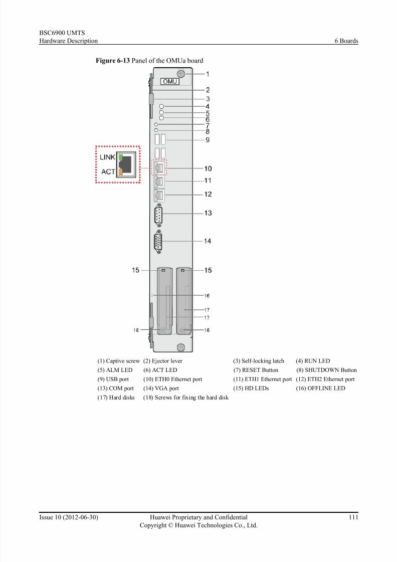
7/30/2019 BSC6900UMTS Hardware Description
http://slidepdf.com/reader/full/bsc6900umts-hardware-description 123/243
Figure 6-13 Panel of the OMUa board
(1) Captive screw (2) Ejector lever (3) Self-locking latch (4) RUN LED
(5) ALM LED (6) ACT LED (7) RESET Button (8) SHUTDOWN Button
(9) USB port (10) ETH0 Ethernet port (11) ETH1 Ethernet port (12) ETH2 Ethernet port
(13) COM port (14) VGA port (15) HD LEDs (16) OFFLINE LED
(17) Hard disks (18) Screws for fixing the hard disk
BSC6900 UMTS
Hardware Description 6 Boards
Issue 10 (2012-06-30) Huawei Proprietary and Confidential
Copyright © Huawei Technologies Co., Ltd.
111

7/30/2019 BSC6900UMTS Hardware Description
http://slidepdf.com/reader/full/bsc6900umts-hardware-description 124/243
NOTE
l To power off the OMUa board, you need to simultaneously pivot the top and bottom ejector levers
away from the front panel of the OMUa board. After the OFFLINE LED is on, turn off the power
switch.
lThe SHUTDOWN button is used only for powering off the board in emergency.
l The RESET button is used to reset the system. It works in the same way as the reset button on the PC.
l Powering off the board by pressing the SHUTDOWN button or resetting the system by pressing the
RESET button may scratch the surface of the hard disks of the OMUa board. Thus, avoid operating
the two buttons whenever possible.
6.11.3 LEDs on the OMUa Board
There are five types of LEDs on the OMUa board: RUN, ALM, ACT, OFFLINE, and HD.
Table 6-43 describes the LEDs on the OMUa board.
Table 6-43 LEDs on the OMUa board
LED Color Status Description
RUN Green ON for 1s and OFF for 1s The board is functional.
ON for 0.125s and OFF
for 0.125s
The board is being started.
ON There is power supply, but the board
is faulty.
OFF There is no power supply, or the
board is faulty.
ALM Red OFF There is no alarm.
ON or blinking There is a fault alarm.
ACT Green ON The board is in active mode.
OFF The board is in standby mode, or the
board is disconnected.
OFFLINE Blue ON The board can be removed.
OFF The board cannot be removed.
ON for 0.125s and OFF
for 0.125s
The board is being switched over to
the other working mode.
HD Green OFF There is no read or write operation
on the hard disk.
Blinking The hard disk is being read or
written.
BSC6900 UMTS
Hardware Description 6 Boards
Issue 10 (2012-06-30) Huawei Proprietary and Confidential
Copyright © Huawei Technologies Co., Ltd.
112

7/30/2019 BSC6900UMTS Hardware Description
http://slidepdf.com/reader/full/bsc6900umts-hardware-description 125/243
6.11.4 Ports on the OMUa Board
There are four USB ports, three GE ports, one serial port COM0-ALM/COM1-BMC, and one
VGA port on the OMUa board.
Table 6-44 describes the ports on the OMUa board.
Table 6-44 Ports on the OMUa board
Port Function Connector Type
USB0-1 and USB2-3 USB ports. These ports are used to
connect USB devices.An operating
system is installed on the server
board, with a user name and
password. Therefore, to use the
USB interface, you must log in to
the operating system first.
Type-A
ETH0 to ETH2 GE ports RJ45
COM0-ALM/COM1-BMC Serial port. This port is used for
system commissioning or for
common serial port usage.This
serial port receives only debugging
data and discards other data.
DB9
VGA Port for the video -
6.11.5 Technical Specifications of the OMUa Board
This section describes the hardware configuration indexes and performance counters of the
OMUa board, including size, power supply, power consumption, weight, hard disk capacity,
memory capacity, working temperature, and working humidity.
Hardware Configuration Indexes
Table 6-45 lists the hardware configuration indexes of the OMUa board.
Table 6-45 Hardware configuration indexes
Counter Name Index of the OMUa Board
Size 248 mm x 64.6mm x 395.4 mm
Power supply Two routes of -48 V DC in redundancy backup mode
(provided by the backplane of the subrack)
Number of logical CPUs 4
Power consumption 120 W
Weight 4.0 kg
BSC6900 UMTS
Hardware Description 6 Boards
Issue 10 (2012-06-30) Huawei Proprietary and Confidential
Copyright © Huawei Technologies Co., Ltd.
113

7/30/2019 BSC6900UMTS Hardware Description
http://slidepdf.com/reader/full/bsc6900umts-hardware-description 126/243
Counter Name Index of the OMUa Board
Hard disk capacity 73 GB or above x 2 (RAID 1)
Memory capacity 2 GB
Temperature required when
working for a long time
5°C to 40°C
Temperature required when
working for a short time
0°C to 50°C
Relative humidity required
when working for a long time
5%-85%
Relative humidity required
when working for a short time
5%-95%
Performance Counters
Table 6-46 describes the performance counters of the OMUa board.
Table 6-46 Performance counters of the OMUa board
Performance Counter Performance Counters of the OMUa Board
Number of recorded
alarms
The maximum number of recorded alarms is 150,000.
Time when the standby
OMU data is
synchronized with the
active OMU data
The standby OMU synchronizes its data with that of the active
OMU board every second.
Duration of the
synchronization between
the active OMU files and
standby OMU files
Seven minutes. The time needed for the synchronization varies
according to the size and quantity of the files to be synchronized.
Duration of the
switchover between theactive and standby OMUs
Time between an OMU switchover request is received and the
switchover is complete. A switchover is complete within four minutes.
Duration of the OMU
restart
Duration of the OMU restart due to OMU fault. This duration
lasts for about three minutes.
The OMUa board contains mechanical hard disk. Adverse environments, such as high
temperature and high altitude, shorten board lifespan.
To ensure the lifespan of the OMUa board, the OMUa board must be protected against vibration,
shock, and abnormal shutdown.
BSC6900 UMTS
Hardware Description 6 Boards
Issue 10 (2012-06-30) Huawei Proprietary and Confidential
Copyright © Huawei Technologies Co., Ltd.
114

7/30/2019 BSC6900UMTS Hardware Description
http://slidepdf.com/reader/full/bsc6900umts-hardware-description 127/243
6.12 PAMU BoardPAMU refers to Power Allocation Monitoring Unit. The PAMU board is installed in the power
distribution box at the top of the cabinet. Each power distribution box accommodates one PAMU
board.
6.12.1 Functions of the PAMU Board
The PAMU board is used to monitor the power distribution box at the top of the BSC6900
cabinet.
The PAMU board performs the following functions:
l Detects the voltage of six -48 V power inputs and reports related alarms
l Detects the status of the power switches for 20 power outputs and reports related alarms
l Enables the switchover when faults occur in the serial port communication, and
communicates with the SCUa board
l Provides two RS485 and two RS232 asynchronous serial ports
6.12.2 Panel of the PAMU Board
On the panel of the PAMU board, there are two LEDs and a mute switch.
Figure 6-14 shows the panel of the PAMU board.
Figure 6-14 Panel of the PAMU board
(1) RUN LED (2) ALM LED (3) Mute switch
BSC6900 UMTS
Hardware Description 6 Boards
Issue 10 (2012-06-30) Huawei Proprietary and Confidential
Copyright © Huawei Technologies Co., Ltd.
115
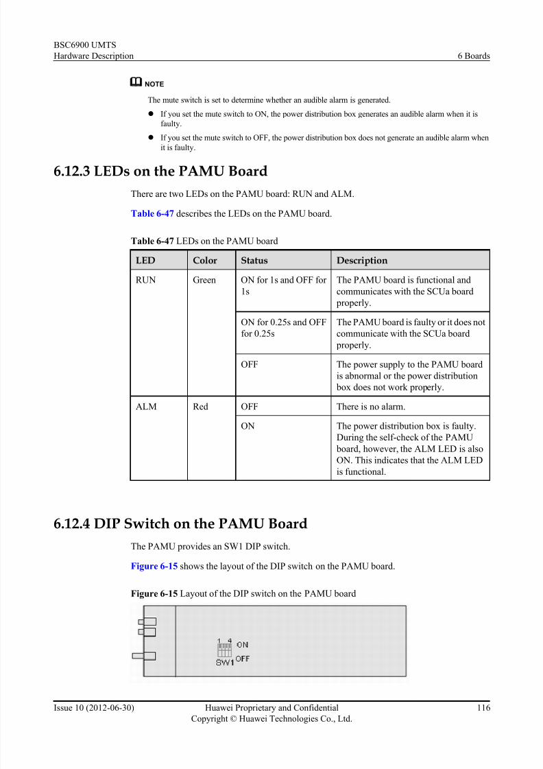
7/30/2019 BSC6900UMTS Hardware Description
http://slidepdf.com/reader/full/bsc6900umts-hardware-description 128/243
NOTE
The mute switch is set to determine whether an audible alarm is generated.
l If you set the mute switch to ON, the power distribution box generates an audible alarm when it is
faulty.
l If you set the mute switch to OFF, the power distribution box does not generate an audible alarm when
it is faulty.
6.12.3 LEDs on the PAMU Board
There are two LEDs on the PAMU board: RUN and ALM.
Table 6-47 describes the LEDs on the PAMU board.
Table 6-47 LEDs on the PAMU board
LED Color Status Description
RUN Green ON for 1s and OFF for
1s
The PAMU board is functional and
communicates with the SCUa board
properly.
ON for 0.25s and OFF
for 0.25s
The PAMU board is faulty or it does not
communicate with the SCUa board
properly.
OFF The power supply to the PAMU board
is abnormal or the power distribution
box does not work properly.
ALM Red OFF There is no alarm.
ON The power distribution box is faulty.
During the self-check of the PAMU
board, however, the ALM LED is also
ON. This indicates that the ALM LED
is functional.
6.12.4 DIP Switch on the PAMU Board
The PAMU provides an SW1 DIP switch.
Figure 6-15 shows the layout of the DIP switch on the PAMU board.
Figure 6-15 Layout of the DIP switch on the PAMU board
BSC6900 UMTS
Hardware Description 6 Boards
Issue 10 (2012-06-30) Huawei Proprietary and Confidential
Copyright © Huawei Technologies Co., Ltd.
116

7/30/2019 BSC6900UMTS Hardware Description
http://slidepdf.com/reader/full/bsc6900umts-hardware-description 129/243
With four bits, the DIP switch SW1 is used to set the address of the PAMU board.
To set the address, first remove the PAMU board and then set the SW1 as described in Table
6-48.
Table 6-48 DIP switch on the PAMU board
Address Bit Setting of DIP Bit Description
0 1 (the most significant
bit)
ON 0
2 ON 0
3 ON 0
4 (the least significant
bit)
ON 0
NOTE
In the BSC6900, the DIP switch on the PAMU board must be set as described in Table 6-48.
6.12.5 Technical Specifications of the PAMU Board
The technical specifications of the PAMU board consist of the dimensions, power supply, power
consumption, and weight.
Table 6-49 describes the technical specifications of the PAMU board.
Table 6-49 Technical specifications of the PAMU board
Item Specification
Dimensions 340 mm × 72 mm
Power supply Two -48 V DC working in active/standby mode
Power consumption 15 W
Weight 0.2 kg
6.13 PEUa BoardPEUa refers to 32-port Packet over E1/T1/J1 interface Unit REV:a. The PEUa board is optional.
It can be installed either in the MPS or in the EPS. The number of PEUa boards to be installed
depends on site requirements. For the MPS, the PEUa board can be installed in slots 14 to 19
and slots 24 to 27. For the EPS, the PEUa board can be installed in slots 14 to 27.
NOTE
If the OMUa boards are not installed in slots 20 to 23 of the MPS, the PEUa boards can be installed in slots 20to 23 of the MPS.
BSC6900 UMTS
Hardware Description 6 Boards
Issue 10 (2012-06-30) Huawei Proprietary and Confidential
Copyright © Huawei Technologies Co., Ltd.
117

7/30/2019 BSC6900UMTS Hardware Description
http://slidepdf.com/reader/full/bsc6900umts-hardware-description 130/243
6.13.1 Functions of the PEUa Board
As an interface board, the PEUa board supports E1/T1 transmission.
The PEUa board performs the following functions:
l Provides 32 channels of IP over PPP/MLPPP over E1/T1
l Provides 128 PPP links or 32 MLPPP groups, each MLPPP group containing 8 MLPPP
links
l Provides the Tributary Protect Switch (TPS) function between the active and standby PEUa
boards
l Transmits, receives, encodes, and decodes 32 channels of E1s/T1s. The E1 transmission
rate is 2.048 Mbit/s; the T1 transmission rate is 1.544 Mbit/s.
l Supports the Iub interfaces
6.13.2 Panel of the PEUa Board
There are LEDs and ports on the panel of the PEUa board.
Figure 6-16 shows the panel of the PEUa board.
Figure 6-16 Panel of the PEUa board
BSC6900 UMTS
Hardware Description 6 Boards
Issue 10 (2012-06-30) Huawei Proprietary and Confidential
Copyright © Huawei Technologies Co., Ltd.
118

7/30/2019 BSC6900UMTS Hardware Description
http://slidepdf.com/reader/full/bsc6900umts-hardware-description 131/243
6.13.3 LEDs on the PEUa Board
There are three LEDs on the PEUa board: RUN, ALM, and ACT.
Table 6-50 describes the LEDs on the PEUa board.
Table 6-50 LEDs on the PEUa board
LED Color Status Description
RUN Green ON for 1s and OFF for 1s The board is functional.
ON for 0.125s and OFF for
0.125s
The board is in loading
state.
ON There is power supply, but
the board is faulty.
OFF There is no power supply,
or the board is faulty.
ALM Red OFF There is no alarm.
ON or blinking There is a fault alarm.
ACT Green ON The board is in active
mode.
OFF The board is in standby
mode.
6.13.4 Ports on the PEUa Board
There are four E1/T1 ports and two clock signal output ports on the PEUa board.
Table 6-51 describes the ports on the PEUa board.
Table 6-51 Ports on the PEUa board
Port Function ConnectorType
E1/T1 (0-7) E1/T1 port, used to transmit and receive E1/T1
signals on channels 0-7
DB44
E1/T1 (8-15) E1/T1 port, used to transmit and receive E1/T1
signals on channels 8-15
DB44
E1/T1 (16-23) E1/T1 port, used to transmit and receive E1/T1
signals on channels 16-23
DB44
E1/T1 (24-31) E1/T1 port, used to transmit and receive E1/T1
signals on channels 24-31
DB44
BSC6900 UMTS
Hardware Description 6 Boards
Issue 10 (2012-06-30) Huawei Proprietary and Confidential
Copyright © Huawei Technologies Co., Ltd.
119

7/30/2019 BSC6900UMTS Hardware Description
http://slidepdf.com/reader/full/bsc6900umts-hardware-description 132/243
Port Function ConnectorType
2M0 and 2M1 Port for 2 MHz clock signal outputs SMB male
connector
6.13.5 DIP Switches on the PEUa Board
The PEUa board provides five DIP switches, namely, S2, S4, S6, S8, and S10.
Figure 6-17 shows the layout of the DIP switches on the PEUa board.
Figure 6-17 Layout of the DIP switches on the PEUa board
(1) Sub-board (2) Bottom plate
BSC6900 UMTS
Hardware Description 6 Boards
Issue 10 (2012-06-30) Huawei Proprietary and Confidential
Copyright © Huawei Technologies Co., Ltd.
120

7/30/2019 BSC6900UMTS Hardware Description
http://slidepdf.com/reader/full/bsc6900umts-hardware-description 133/243
NOTE
l All DIP switches are on the front panel of the sub-board. The front panel is combined with the bottom
plate, so the DIP switches are not exposed.
l DIP switches S2, S4, S6, S8, and S10 are set from the side. As shown in Figure 6-17, there are two
square holes between DIP switches, one between S2 and S4, and the other between S8 and S6. Throughthe two holes, you can set S2, S4, S8, and S6. DIP switch S10 is located in the right corner of the sub-
board, and thus you can set S10 along the side. The direction of the arrow in Figure 6-17 is to turn
inwards. To set the bits of S2, S4, S6, or S8 to ON, turn them inwards. To set the bits of S2, S4, S6, or
S8 to OFF, turn them outwards. To set the bits of S10 to ON, turn them outwards. To set the bits of
S10 to OFF, turn them inwards.
l You can also run the SET E1T1 command on the LMT to set S10. If there is any inconsistency between
the physical setting of S10 on the PEUa board and the setting of S10 by command, take the setting by
command as the criterion. By default, the working mode of S10 is set to E1. You can also run the SET
E1T1 command on the LMT to change the working mode of S10 from E1 mode to E1 balanced mode,
E1 unbalanced mode, or T1 mode. When you run the SET E1T1 command to set the support for
balanced and unbalanced modes parameter to No and set the working mode of S10 to E1, you must
also manually set the bits of S10 to set the working mode of S10 to E1 balanced mode or E1 unbalanced
mode.
l If signals are transmitted in E1 unbalanced mode, the signals are transmitted through the 75-ohm coaxial
cable and the TX end of the cable is grounded, that is, the corresponding DIP bit is set to ON. If signals
are transmitted in E1(T1) balanced mode, the signals are transmitted through the 120-ohm twisted pair
cable and the TX end of the cable is not grounded, that is, the corresponding DIP bit is set to OFF.
DIP switches S2, S4, S6, and S8 on the PEUa board are used to enable or disable the grounding
of 0 to 31 E1s/T1s/J1s at the TX end. DIP switch S10 is used to set the working mode to E1
balanced mode, E1 unbalanced mode, T1 mode, or J1 mode. Table 6-52 describes the DIP
switches on the PEUa board.
Table 6-52 Description about DIP switches on the PEUa board
DIPSwitch
Bit Description Setting of DIPSwitch
Meaning
S2 1-8 TX ground switch of
E1s/T1s/J1s 24 to 31
ON Setting the
working mode to
E1 unbalanced
mode
OFF Setting the
working mode to
other modes
S4 1-8 TX ground switch of
E1s/T1s/J1s 16 to 23
ON Setting the
working mode to
E1 unbalanced
mode
OFF Setting the
working mode to
other modes
S6 1-8 TX ground switch of
E1s/T1s/J1s 0 to 7
ON Setting the
working mode to
E1 unbalanced
mode
BSC6900 UMTS
Hardware Description 6 Boards
Issue 10 (2012-06-30) Huawei Proprietary and Confidential
Copyright © Huawei Technologies Co., Ltd.
121

7/30/2019 BSC6900UMTS Hardware Description
http://slidepdf.com/reader/full/bsc6900umts-hardware-description 134/243
DIPSwitch
Bit Description Setting of DIPSwitch
Meaning
OFF Setting the
working mode to
other modes
S8 1-8 TX ground switch of
E1s/T1s/J1s 8 to 15
ON Setting the
working mode to
E1 unbalanced
mode
OFF Setting the
working mode to
other modes
S10 1-2 DIP switch for setting theworking mode,
consisting of two bits
(ON, ON) Setting theworking mode to
E1 unbalanced
mode
(OFF, ON) Setting the
working mode to
E1 balanced
mode
(ON, OFF) Setting the
working mode to
T1 mode
(OFF, OFF) Setting the
working mode to
J1 mode
NOTE
All the DIP switches are set to E1 balanced mode by default, that is, all the bits of S2, S4, S6, and S8 are
set to OFF. For S10, the first bit is set to OFF, and the second bit to ON.
6.13.6 Technical Specifications of the PEUa BoardThe technical specifications of the PEUa board consist of hardware specifications and
specifications of the board processing capability. The hardware specifications consist of the
dimensions, power supply, power consumption, weight, operating temperature, and relative
humidity.
Table 6-53 describes the hardware specifications of the PEUa board.
Table 6-53 Hardware specifications of the PEUa board
Item Specification
Dimensions 248 mm x 32.3mm x 395.4 mm
BSC6900 UMTS
Hardware Description 6 Boards
Issue 10 (2012-06-30) Huawei Proprietary and Confidential
Copyright © Huawei Technologies Co., Ltd.
122

7/30/2019 BSC6900UMTS Hardware Description
http://slidepdf.com/reader/full/bsc6900umts-hardware-description 135/243
Item Specification
Power supply Two -48 V DC working in active/standby mode.
The backplane of the subrack is responsible for
the power supply.
Power consumption 27.53 W
Weight 1.30 kg
Operating temperature (long-term) 0°C to 45°C
Operating temperature (short-term) -5°C to +55°C
Relative humidity (long-term) 5% to 85%
Relative humidity (short-term) 5% to 95%
Table 6-54 describes the specifications of the board processing capability.
Table 6-54 Specifications of the board processing capability
Item Specification
Number of UDP (User Datagram Protocol)
ports
23,000
Session setup/release times 500/s
Iub Number of NodeBs 32
Speech service in the CS domain 2,800 Erlang
Data service in the CS domain 850 Erlang
Maximum payload throughput
(UL)
60 Mbit/s
Maximum payload throughput
(DL)
60 Mbit/s
Maximum payload throughput
(UL+DL)
120 Mbit/s
NOTE
l The specifications described in the preceding table apply to boards in active/standby mode. If a board
is configured in independent mode, the specifications cannot be reached.
l The preceding specifications are the maximum capability regarding the corresponding service.
l The data service in the CS domain indicates the 64 kbit/s video phone service.
l The number of session setup/release times indicates the signaling processing capacity of an Iub/Iu/Iur-
interface board.
l The throughput specifications are based on the conditions of UL 64 kbit/s and DL 384 kbit/s.
BSC6900 UMTS
Hardware Description 6 Boards
Issue 10 (2012-06-30) Huawei Proprietary and Confidential
Copyright © Huawei Technologies Co., Ltd.
123

7/30/2019 BSC6900UMTS Hardware Description
http://slidepdf.com/reader/full/bsc6900umts-hardware-description 136/243
6.14 PFCU Board
PFCU refers to Fan Control Unit. The PFCU board is installed in the front of the fan box. Each
fan box is configured with one PFCU board.
6.14.1 Functions of the PFCU Board
The PFCU board is used to monitor the fan box.
The PFCU board performs the following functions:
l Monitors the working status of the fans in the fan box and displays the status through the
LED
l Communicates with the SCUa board, to report the working status of the fan box
l Collects temperature information and detects the temperature through temperature sensors
l Provides Pulse-Width Modulation (PWM) control signals which are used to adjust the fan
speed
l Reports the working status and alarms of the fans in the fan box through the LED
6.14.2 DIP Switch on the PFCU Board
The PFCU board has one DIP switch, which is named SW1 and consists of four bits. The DIP
switch is used to set the address of the PFCU board. When the PFCU board is configured in a
fan box of the service subrack, the address of the PFCU board is set to 1. When the PFCU board
is configured in the independent fan subrack, the address of the PFCU board is set to 4.
DIP Switch on the PFCU Board (in a Fan Box of the service subrack)
Figure 6-18 shows the DIP switch on the PFCU board.
Figure 6-18 DIP switch on the PFCU board
To set the address of the PFCU board, remove the fan box, and then set SW1 as described in
Table 6-55. For how to remove the fan box, see Replacing the Fan Box. After the setting, the
address of the PFCU board is 1.
BSC6900 UMTS
Hardware Description 6 Boards
Issue 10 (2012-06-30) Huawei Proprietary and Confidential
Copyright © Huawei Technologies Co., Ltd.
124

7/30/2019 BSC6900UMTS Hardware Description
http://slidepdf.com/reader/full/bsc6900umts-hardware-description 137/243
Table 6-55 DIP switch on the PFCU board (in a fan box of the service subrack)
DIP Switch Bit Setting of DIPSwitch
Description
SW1 1 (the least significant bit)
OFF 1
2 ON 0
3 ON 0
4 (the most significant
bit)
ON 0
DIP Switch on the PFCU Board (in the Independent Fan Subrack)Figure 6-19 shows the DIP switch on the PFCU board.
Figure 6-19 DIP switch on the PFCU board
To set the address of the PFCU board, remove the fan box, and then set SW1 as described in
Table 6-56. For how to remove the fan box, see Replacing the Fan Box. After the setting, the
address of the PFCU board is 4.
Table 6-56 DIP switch on the PFCU board (in the independent fan subrack)
DIP Switch Bit Setting of DIPSwitch
Description
SW1 1 (the least significant bit) ON 0
2 ON 0
3 OFF 1
4 (the most significant
bit)
ON 0
NOTE
The DIP switch on the PFCU board of the BSC6900 must be set according to the preceding descriptions.
BSC6900 UMTS
Hardware Description 6 Boards
Issue 10 (2012-06-30) Huawei Proprietary and Confidential
Copyright © Huawei Technologies Co., Ltd.
125

7/30/2019 BSC6900UMTS Hardware Description
http://slidepdf.com/reader/full/bsc6900umts-hardware-description 138/243
6.14.3 Technical Specifications of the PFCU Board
The technical specifications of the PFCU board consist of the dimensions, input voltage range,
frequency of PWM signals, detectable temperature range, and requirement for fan speed
adjustment.
Table 6-57 describes the technical specifications of the PFCU board.
Table 6-57 Technical specifications of the PFCU board
Item Specification
Dimensions 270 mm x 35 mm
Input voltage range -40 V DC to -57 V DC
Frequency of PWM signals 1 kHz
Detectable temperature range -5°C to +55°C(basic requirement)
Requirement for fan speed adjustment The speed of the fans can be adjusted from 55%
to 100% of the full speed.
6.15 PFCB Board
PFCB refers to Fan Control Board. The PFCB board is installed in the front of the fan box. Each
fan box is configured with one PFCB board.
6.15.1 Functions of the PFCB Board
The PFCB board is used to monitor the fan box.
The PFCB board performs the following functions:
l Monitors the working status of the fans in the fan box and displays the status through the
LED
l Communicates with the SCUa board, to report the working status of the fan box, and
responds to the fan speed adjustment commandl Collects temperature information through temperature sensors and intelligently adjusts the
fan speed based on the temperature information
l Provides Pulse-Width Modulation (PWM) control signals which are used to adjust the fan
speed
l Reports the working status and alarms of the fans in the fan box through the LED
6.15.2 Pins on the PFCB Board
The PFCB board provides eight pairs of pins for jumpers. After being connected to jumpers,
these pins are used to set the address and working mode of the PFCB board. The settings of these
pins depend on the installation position of the PFCB board.
BSC6900 UMTS
Hardware Description 6 Boards
Issue 10 (2012-06-30) Huawei Proprietary and Confidential
Copyright © Huawei Technologies Co., Ltd.
126

7/30/2019 BSC6900UMTS Hardware Description
http://slidepdf.com/reader/full/bsc6900umts-hardware-description 139/243
7/30/2019 BSC6900UMTS Hardware Description
http://slidepdf.com/reader/full/bsc6900umts-hardware-description 140/243
NOTE
The pins on the PFCB board of the BSC6900 must be set according to the preceding descriptions.
6.15.3 Technical Specifications of the PFCU Board
The technical specifications of the PFCB board consist of the dimensions, input voltage range,
frequency of Pulse Width Modulation (PWM) signals, detectable temperature range, and
requirement for fan speed adjustment.
Table 6-60 describes the technical specifications of the PFCB board.
Table 6-60 Technical specifications of the PFCB board
Item SpecificationDimensions 390 mm × 50 mm
Input voltage range -40 V DC to -57 V DC
Frequency of PWM signals 1 kHz
Detectable temperature range -5°C to +55°C(basic requirement)
Requirement for fan speed adjustment The speed of the fans can be adjusted from 55%
to 100% of the full speed.
6.16 POUa Board
POUa refers to 2-port IP over channelized Optical STM-1/OC-3 interface Unit REV:a. The
POUa board is optional. It can be installed either in the MPS or in the EPS. The number of POUa
boards to be installed depends on site requirements. For the MPS, the POUa board can be
installed in slots 14 to 19 and slots 24 to 27. For the EPS, the POUa board can be installed in
slots 14 to 27.
NOTE
If the OMUa boards are not installed in slots 20 to 23 of the MPS, the POUa boards can be installed in slots 20
to 23 of the MPS.
6.16.1 Functions of the POUa Board
As an interface board, the POUa board supports channelized STM-1/OC-3 transmission based
on IP protocol.
The POUa board performs the following functions:
l Provides two channels over channelized optical STM-1/OC-3 ports based on IP protocol
l Supports IP over E1/T1 over SDH/SONET
l Provides MLPPP groups.
l Supports 126 E1s or 168 T1s
BSC6900 UMTS
Hardware Description 6 Boards
Issue 10 (2012-06-30) Huawei Proprietary and Confidential
Copyright © Huawei Technologies Co., Ltd.
128

7/30/2019 BSC6900UMTS Hardware Description
http://slidepdf.com/reader/full/bsc6900umts-hardware-description 141/243
l Provides the Automatic Protection Switching (APS) function between the active and
standby POUa boards
l Supports the Iub interfaces
l Supports the extraction of line clock signals
6.16.2 Panel of the POUa Board
There are LEDs and ports on the panel of the POUa board.
Figure 6-22 shows the panel of the POUa board.
Figure 6-22 Panel of the POUa board
6.16.3 LEDs on the POUa Board
There are three LEDs on the POUa board: RUN, ALM, and ACT.
BSC6900 UMTS
Hardware Description 6 Boards
Issue 10 (2012-06-30) Huawei Proprietary and Confidential
Copyright © Huawei Technologies Co., Ltd.
129

7/30/2019 BSC6900UMTS Hardware Description
http://slidepdf.com/reader/full/bsc6900umts-hardware-description 142/243
Table 6-61 describes the LEDs on the POUa board.
Table 6-61 LEDs on the POUa board
LED Color Status Description
RUN Green ON for 1s and OFF for 1s The board is functional.
ON for 0.125s and OFF for
0.125s
The board is in loading
state.
ON There is power supply, but
the board is faulty.
OFF There is no power supply,
or the board is faulty.
ALM Red OFF There is no alarm.
ON or blinking There is a fault alarm.
ACT Green ON The board is in active
mode.
OFF The board is in standby
mode.
6.16.4 Ports on the POUa Board
There are two optical ports and two clock signal output ports on the POUa board.
Table 6-62 describes the ports on the POUa board.
Table 6-62 Ports on the POUa board
PortLocation
Port Function Connector Type
Multiplexing E1 PortNumber
Multiplexing T1PortNumber
The first port
under LEDs
RX Receiving
optical port
LC/PC 0 to 62 0 to 83
TX Transmitting
optical port
The second
port under
LEDs
RX Receiving
optical port
LC/PC 63 to 125 84 to 167
TX Transmitting
optical port
Right above
the sign
"PARC"
2M0 and
2M1
Port for 2 MHz
clock signal
outputs
SMB male
connector
- -
BSC6900 UMTS
Hardware Description 6 Boards
Issue 10 (2012-06-30) Huawei Proprietary and Confidential
Copyright © Huawei Technologies Co., Ltd.
130

7/30/2019 BSC6900UMTS Hardware Description
http://slidepdf.com/reader/full/bsc6900umts-hardware-description 143/243
6.16.5 DIP Switches on the POUa Board
The POUa board provides two DIP switches, both of which are labeled S1. The two DIP switches
are used to set the mode of the two STM-1/OC-3 optical ports.
Layout of the DIP Switches
Figure 6-23 shows the layout of the DIP switches on the POUa board.
Figure 6-23 Layout of the DIP switches on the POUa board
(1) Sub-board (2) Bottom plate
CAUTION
All the DIP switches on the POUa board are on the front panel of the sub-board. The front panel
is faced to and combined with the bottom plate, and so the DIP switches are hidden in between.
BSC6900 UMTS
Hardware Description 6 Boards
Issue 10 (2012-06-30) Huawei Proprietary and Confidential
Copyright © Huawei Technologies Co., Ltd.
131

7/30/2019 BSC6900UMTS Hardware Description
http://slidepdf.com/reader/full/bsc6900umts-hardware-description 144/243
Description of the DIP Switches
Table 6-63 describes the DIP switches on the POUa board.
Table 6-63 Description of the DIP switches on the POUa board
DIP Switch Bit Setting of DIP Bit Meaning
S1 1-2 (ON, ON) Setting loading mode
to JTAG configuration
(OFF, OFF) Setting loading mode
to CPU slave parallel
configuration
3 ON Setting working mode
to T1 mode
OFF Setting working mode
to E1 mode
4 ON Setting the mapped
path to AU3
OFF Setting the mapped
path to AU4
5 ON Setting the
information structure
to TU11
OFF Setting the
information structure
to TU12
6 ON SONET
OFF SDH
7 - Reserved
8 - Reserved
NOTE
All the bits of the two DIP switches are set to OFF by default.
6.16.6 Technical Specifications of the POUa Board
The technical specifications of the POUa board consist of hardware specifications and
specifications of the optical ports and board processing capability. The hardware specifications
consist of the dimensions, power supply, power consumption, weight, operating temperature,
and relative humidity.
Table 6-64 describes the hardware specifications of the POUa board.
BSC6900 UMTS
Hardware Description 6 Boards
Issue 10 (2012-06-30) Huawei Proprietary and Confidential
Copyright © Huawei Technologies Co., Ltd.
132

7/30/2019 BSC6900UMTS Hardware Description
http://slidepdf.com/reader/full/bsc6900umts-hardware-description 145/243

7/30/2019 BSC6900UMTS Hardware Description
http://slidepdf.com/reader/full/bsc6900umts-hardware-description 146/243
NOTE
l The specifications described in the preceding table apply to boards in active/standby mode. If a board
is configured in independent mode, the specifications cannot be reached.
l The preceding specifications are the maximum capability regarding the corresponding service.
l The data service in the CS domain indicates the 64 kbit/s video phone service.
l The number of session setup/release times indicates the signaling processing capacity of an Iub/Iu/Iur-
interface board.
l The throughput specifications are based on the conditions of UL 64 kbit/s and DL 384 kbit/s.
Table 6-66 describes the specifications of the optical ports on the POUa board.
Table 6-66 Specifications of the optical ports on the POUa board
Item Specification
Optical Module 155
M-1310 nm-2 km-MM-SFP
Optical Module 155
M-1310 nm-15 km-SM-ESFP
Optical Module 155
M-1310 nm-40 km-SM-ESFP
Mode Multi-mode Single mode Single mode
Type LC/PC LC/PC LC/PC
Maximum
optical
transmission
distance
2 km 15 km 40 km
Maximum
output optical power
-14.0 dBm -8.0 dBm 0.0 dBm
Minimum
output optical
power
-19.0 dBm -15.0 dBm -5.0 dBm
Minimum
receiver
sensitivity
-30.0 dBm -31.0 dBm -37.0 dBm
Center
wavelength
1,310 nm 1,310 nm 1,310 nm
Transmission
rate
155.52 Mbit/s 155.52 Mbit/s 155.52 Mbit/s
6.17 POUc Board
POUc refers to 4-port IP over channelized Optical STM-1/OC-3 interface Unit REV:c. The
POUc board is optional. It can be installed in the MPS and in the EPS. The number of POUc
boards to be installed depends on site requirements. For the MPS, the POUc board can be
installed in slots 14 to 19 and slots 24 to 27. For the EPS, the POUc board can be installed inslots 14 to 27.
BSC6900 UMTS
Hardware Description 6 Boards
Issue 10 (2012-06-30) Huawei Proprietary and Confidential
Copyright © Huawei Technologies Co., Ltd.
134

7/30/2019 BSC6900UMTS Hardware Description
http://slidepdf.com/reader/full/bsc6900umts-hardware-description 147/243
NOTE
If the OMUa boards are not installed in slots 20 to 23 of the MPS, the POUc boards can be installed in slots 20
to 23 of the MPS.
6.17.1 Functions of the POUc BoardAs an interface board, the POUc board supports IP over channelized STM-1/OC-3 transmission.
The POUc board performs the following functions:
l Provides four channels over channelized optical STM-1/OC-3 ports based on IP protocol
l Supports the PPP function
l Extracts line clock signals
l Provides the Automatic Protection Switching (APS) function between the active and
standby POUc boards
l Supports the Iur, and Iub interfaces
6.17.2 Panel of the POUc Board
There are LEDs and ports on the panel of the POUc board.
Figure 6-24 shows the panel of the POUc board.
BSC6900 UMTS
Hardware Description 6 Boards
Issue 10 (2012-06-30) Huawei Proprietary and Confidential
Copyright © Huawei Technologies Co., Ltd.
135

7/30/2019 BSC6900UMTS Hardware Description
http://slidepdf.com/reader/full/bsc6900umts-hardware-description 148/243
Figure 6-24 Panel of the POUc board
6.17.3 LEDs on the POUc BoardThere are four types of LEDs on the POUc board: RUN, ALM, ACT, and LOS.
Table 6-67 describes the LEDs on the POUc board.
Table 6-67 LEDs on the POUc board
LED Color Status Description
RUN Green ON for 1s and OFF for 1s The board is functional.
ON for 0.125s and OFF for
0.125s
The board is in loading state.
BSC6900 UMTS
Hardware Description 6 Boards
Issue 10 (2012-06-30) Huawei Proprietary and Confidential
Copyright © Huawei Technologies Co., Ltd.
136

7/30/2019 BSC6900UMTS Hardware Description
http://slidepdf.com/reader/full/bsc6900umts-hardware-description 149/243
LED Color Status Description
ON There is power supply, but the board
is faulty.
OFF There is no power supply, or the board is faulty.
ALM Red OFF There is no alarm.
ON or blinking There is a fault alarm.
ACT Green ON The board is in active mode.
OFF The board is in standby mode.
LOS Green ON The STM-1 port does not receive
signals properly.
OFF The STM-1 port receives signals
properly.
6.17.4 Ports on the POUc Board
There are four optical ports on the POUc board.
Table 6-68 describes the ports on the POUc board.
Table 6-68 Ports on the POUc board
PortNumber
Port Function ConnectorType
Multiplexing E1 PortNumber
Multiplexing T1 PortNumber
0 RX Receiving
optical port
LC/PC 0 to 62 0 to 83
TX Transmitting
optical port
1 RX Receivingoptical port
LC/PC 63 to 125 84 to 167
TX Transmitting
optical port
2 RX Receiving
optical port
LC/PC 126 to 188 168 to 251
TX Transmitting
optical port
3 RX Receiving
optical port
LC/PC 189 to 251 252 to 335
BSC6900 UMTS
Hardware Description 6 Boards
Issue 10 (2012-06-30) Huawei Proprietary and Confidential
Copyright © Huawei Technologies Co., Ltd.
137

7/30/2019 BSC6900UMTS Hardware Description
http://slidepdf.com/reader/full/bsc6900umts-hardware-description 150/243
PortNumber
Port Function ConnectorType
Multiplexing E1 PortNumber
Multiplexing T1 PortNumber
TX Transmitting
optical port
6.17.5 Technical Specifications of the POUc Board
The technical specifications of the POUc board consist of hardware specifications and
specifications of the optical ports and board processing capability. The hardware specifications
consist of the dimensions, power supply, power consumption, weight, operating temperature,
and relative humidity.
Table 6-69 describes the hardware specifications of the POUc board.
Table 6-69 Hardware specifications of the POUc board
Item Specification
Dimensions 248 mm x 32.3mm x 395.4 mm
Power supply Two -48 V DC working in active/standby mode.
The backplane of the subrack is responsible for
the power supply.
Power consumption 77.25 W
Weight 1.50 kg
Operating temperature (long-term) 0°C to 45°C
Operating temperature (short-term) -5°C to +55°C
Relative humidity (long-term) 5% to 85%
Relative humidity (short-term) 5% to 95%
Table 6-70 describes the specifications of the board processing capability.
Table 6-70 S pecifications of the board processing capability
Item Specification
Number of UDP (User Datagram Protocol)
ports
79,000
Session setup/release times 3,000/s
Iub Number of NodeBs 252
Speech service in the CS domain 18,000 Erlang
BSC6900 UMTS
Hardware Description 6 Boards
Issue 10 (2012-06-30) Huawei Proprietary and Confidential
Copyright © Huawei Technologies Co., Ltd.
138

7/30/2019 BSC6900UMTS Hardware Description
http://slidepdf.com/reader/full/bsc6900umts-hardware-description 151/243
Item Specification
Data service in the CS domain 6,000 Erlang
Maximum payload throughput
(UL)
400 Mbit/s
Maximum payload throughput
(DL)
400 Mbit/s
Maximum payload throughput
(UL+DL)
800 Mbit/s
Iur Speech service in the CS domain 18,000 Erlang
Data service in the CS domain 6,000 Erlang
Maximum payload throughput
(UL)
400 Mbit/s
Maximum payload throughput
(DL)
400 Mbit/s
Maximum payload throughput
(UL+DL)
800 Mbit/s
NOTE
l The specifications described in the preceding table apply to boards in active/standby mode. If a board
is configured in independent mode, the specifications cannot be reached.
l The preceding specifications are the maximum capability regarding the corresponding service.
l The data service in the CS domain indicates the 64 kbit/s video phone service.
l The number of session setup/release times indicates the signaling processing capacity of an Iub/Iu/Iur-
interface board.
l The throughput specifications are based on the conditions of UL 64 kbit/s and DL 384 kbit/s.
Table 6-71 describes the specifications of the optical ports on the POUc board.
Table 6-71 Specifications of the optical ports on the POUc board
Item Specification
Optical Module 155M-1310 nm-2 km-MM-SFP
Optical Module 155M-1310 nm-15 km-SM-ESFP
Optical Module 155M-1310 nm-40 km-SM-ESFP
Mode Multi-mode Single mode Single mode
Type LC/PC LC/PC LC/PC
Maximum
optical
transmission
distance
2 km 15 km 40 km
BSC6900 UMTS
Hardware Description 6 Boards
Issue 10 (2012-06-30) Huawei Proprietary and Confidential
Copyright © Huawei Technologies Co., Ltd.
139

7/30/2019 BSC6900UMTS Hardware Description
http://slidepdf.com/reader/full/bsc6900umts-hardware-description 152/243

7/30/2019 BSC6900UMTS Hardware Description
http://slidepdf.com/reader/full/bsc6900umts-hardware-description 153/243
Figure 6-25 Panel of the SCUa board
6.18.3 LEDs on the SCUa BoardAmong all the LEDs on the SCUa board, RUN, ALM, and ACT indicate the status of the SCUa
board, and other LEDs indicate the status of Ethernet ports. There are two LEDs at each Ethernet
port: LINK and ACT.
Table 6-72 describes the LEDs on the SCUa board.
Table 6-72 LEDs on the SCUa board
LED Color Status Description
RUN Green ON for 1s and OFF for 1s The board is functional.
BSC6900 UMTS
Hardware Description 6 Boards
Issue 10 (2012-06-30) Huawei Proprietary and Confidential
Copyright © Huawei Technologies Co., Ltd.
141

7/30/2019 BSC6900UMTS Hardware Description
http://slidepdf.com/reader/full/bsc6900umts-hardware-description 154/243
LED Color Status Description
ON for 0.125s and OFF for
0.125s
The board is in loading
state.
ON There is power supply, butthe board is faulty.
OFF There is no power supply,
or the board is faulty.
ALM Red OFF There is no alarm.
ON or blinking There is a fault alarm.
ACT Green ON The board is in active
mode.
OFF The board is in standbymode.
LINK (at the
Ethernet port)
Green ON The link is well connected.
OFF The link is disconnected.
ACT (at the
Ethernet port)
Green OFF There is no data
transmission over the
Ethernet port.
Blinking There is data transmission
over the Ethernet port.
6.18.4 Ports on the SCUa Board
There are twelve 10/100/1000BASE-T ports, one COM port, one clock signal input port, and
one TESTOUT port on the SCUa board.
Table 6-73 describes the ports on the SCUa board.
Table 6-73 Ports on the SCUa board
Port Function ConnectorType
10/100/100
0BASE-T0
to
10/100/100
0BASE-T9
10M/100M/1000M Ethernet ports, used for the inter-
subrack connection.
RJ45
BSC6900 UMTS
Hardware Description 6 Boards
Issue 10 (2012-06-30) Huawei Proprietary and Confidential
Copyright © Huawei Technologies Co., Ltd.
142

7/30/2019 BSC6900UMTS Hardware Description
http://slidepdf.com/reader/full/bsc6900umts-hardware-description 155/243
Port Function ConnectorType
10/100/100
0BASE-
T10 to
10/100/100
0BASE-
T11
10M/100M/1000M Ethernet ports, the two ports are unused
in the BSC6900.
RJ45
COM Serial port for commissioning.This serial port receives only
debugging data and discards other data.
RJ45
CLKIN Port for reference clock signal inputs, used to receive the 8
kHz and the 1 PPS clock signals from the GCUa/GCGa
board.
RJ45
TESTOUT Port for clock signal outputs. The clock signals are used for testing.
SMB maleconnector
6.18.5 Technical Specifications of the SCUa Board
The technical specifications of the SCUa board consist of the dimensions, power supply, power
consumption, weight, operating temperature, relative humidity, and switching capacity.
Table 6-74 describes the technical specifications of the SCUa board.
Table 6-74 Technical specifications of the SCUa board
Item Specification
Dimensions 248 mm x 32.3mm x 395.4 mm
Power supply Two -48 V DC working in active/standby mode.
The backplane of the subrack is responsible for
the power supply.
Power consumption 54.5 W
Weight 1.2 kg
Operating temperature (long-term) 0°C to 45°C
Operating temperature (short-term) -5°C to +55°C
Relative humidity (long-term) 5% to 85%
Relative humidity (short-term) 5% to 95%
Switching capacity 60 Gbit/s
BSC6900 UMTS
Hardware Description 6 Boards
Issue 10 (2012-06-30) Huawei Proprietary and Confidential
Copyright © Huawei Technologies Co., Ltd.
143

7/30/2019 BSC6900UMTS Hardware Description
http://slidepdf.com/reader/full/bsc6900umts-hardware-description 156/243
6.19 SPUa Board
SPUa refers to Signaling Processing Unit REV:a. The SPUa board is optional. Two to ten SPUa
boards can be installed in the MPS/EPS. For the MPS, the SPUa boards can be installed in slots
0 to 5, slots 8 to 11, slots 14 to 19, and slots 24 to 27. For the EPS, the SPUa boards can be
installed in slots 0 to 5 and slots 8 to 27.
NOTE
If the OMUa boards are not installed in slots 20 to 23 of the MPS, the SPUa boards can be installed in slots 20
to 23 of the MPS.
6.19.1 Functions of the SPUa Board
Loaded with different software, the SPUa board is functionally divided into main control SPUa
board and non-main control SPUa board. The main control SPUa board is used to manage theUMTS user plane resources, control plane resources, and transmission resources in the system
and process the UMTS services on the control plane. The non-main control SPUa board is used
to process the UMTS services on the control plane.
NOTE
Run the ADD BRD command to configure the logic function type of an SPUa board:
l If Logical function type is set to RUCP, the SPUa board serves as a main control SPUa board.
l If Logical function type is set to UCP, the SPUa board serves as a non-main control SPUa board.
Main Control SPUa Board
The main control SPUa board has four logical subsystems.
Subsystem 0 of the main control SPUa board is the Main Processing Unit (MPU). It is used to
manage the user plane resources, control plane resources, and transmission resources of the
system. The functions are described as follows:
l Managing the user plane resources; managing the load sharing of the user plane resources
between subracks
l Maintaining the load of the control plane within the subrack; exchanging the load
information on the control planes between subracks
l Providing functions such as the logical main control function of the BSC6900, the IMSI-
RNTI maintenance and query, and the IMSI-CNid maintenance and query
l Forwarding the RRC connection request message to implement the sharing of user plane
resources and sharing of control plane resources in the BSC6900
Subsystems 1 to 3 of the main control SPUa board belong to the CPU for Service (CPUS), which
is used to process the services on the control plane. The functions are described as follows:
l Processing upper-layer signaling over the Uu, Iu, Iur, and Iub interfaces
l Processing transport layer signaling
l Allocating and managing the various resources that are necessary for service setup, and
establishing signaling and service connections
l Processing RFN signaling
BSC6900 UMTS
Hardware Description 6 Boards
Issue 10 (2012-06-30) Huawei Proprietary and Confidential
Copyright © Huawei Technologies Co., Ltd.
144
7/30/2019 BSC6900UMTS Hardware Description
http://slidepdf.com/reader/full/bsc6900umts-hardware-description 157/243
Non-Main Control SPUa Board
The non-main control SPUa board has four logical subsystems.
The four subsystems of the non-main control SPUa board belong to the CPUS, which is used to
process the services on the control plane. The functions are described as follows:
l Processing upper-layer signaling over the Uu, Iu, Iur, and Iub interfaces
l Processing transport layer signaling
l Allocating and managing the various resources that are necessary for service setup, and
establishing signaling and service connections
l Processing RFN signaling
6.19.2 Panel of the SPUa Board
There are LEDs and ports on the panel of the SPUa board.
Figure 6-26 shows the panel of the SPUa board.
BSC6900 UMTS
Hardware Description 6 Boards
Issue 10 (2012-06-30) Huawei Proprietary and Confidential
Copyright © Huawei Technologies Co., Ltd.
145
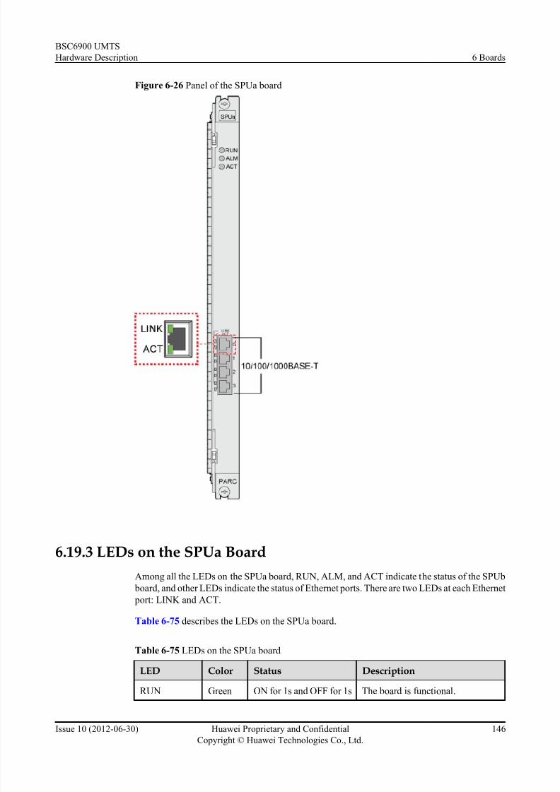
7/30/2019 BSC6900UMTS Hardware Description
http://slidepdf.com/reader/full/bsc6900umts-hardware-description 158/243
Figure 6-26 Panel of the SPUa board
6.19.3 LEDs on the SPUa BoardAmong all the LEDs on the SPUa board, RUN, ALM, and ACT indicate the status of the SPUb
board, and other LEDs indicate the status of Ethernet ports. There are two LEDs at each Ethernet
port: LINK and ACT.
Table 6-75 describes the LEDs on the SPUa board.
Table 6-75 LEDs on the SPUa board
LED Color Status Description
RUN Green ON for 1s and OFF for 1s The board is functional.
BSC6900 UMTS
Hardware Description 6 Boards
Issue 10 (2012-06-30) Huawei Proprietary and Confidential
Copyright © Huawei Technologies Co., Ltd.
146

7/30/2019 BSC6900UMTS Hardware Description
http://slidepdf.com/reader/full/bsc6900umts-hardware-description 159/243

7/30/2019 BSC6900UMTS Hardware Description
http://slidepdf.com/reader/full/bsc6900umts-hardware-description 160/243
Table 6-77 Technical specifications of the SPUa board
Item Specification
Dimensions 248 mm x 32.3mm x 395.4 mm
Power supply Two -48 V DC working in active/standby mode.
The backplane of the subrack is responsible for
the power supply.
Power consumption 76.60 W
Weight 1.60 kg
Operating temperature (long-term) 0°C to 45°C
Operating temperature (short-term) -5°C to +55°C
Relative humidity (long-term) 5% to 85%
Relative humidity (short-term) 5% to 95%
Processing capability of the main control
SPUa board
Supporting 100 NodeBs, 300 cells, and 67,500
BHCAs
Processing capability of the non-main
control SPUa board
Supporting 100 NodeBs, 300 cells, and 90,000
Busy Hour Call Attempts (BHCAs)
NOTE
The preceding BHCA specification is calculated on the basis of Huawei traffic model. The BHCAspecification configured for an SPU depends on the actual traffic model.
6.20 SPUb Board
SPUb refers to Signaling Processing Unit REV:b. The SPUb board is optional. Two to ten SPUb
boards can be installed in the MPS and in the EPS. For the MPS, the SPUb boards can be installed
in slots 0 to 5, slots 8 to 11, slots 14 to 19, and slots 24 to 27. For the EPS, the SPUb boards can
be installed in slots 0 to 5, slots 8 to 13, and slots 14 to 27.
NOTE
If the OMUa boards are not installed in slots 20 to 23 of the MPS, the SPUb boards can be installed in slots 20to 23 of the MPS.
6.20.1 Functions of the SPUb Board
Loaded with different software, the SPUb board is functionally divided into main control SPUb
board and non-main control SPUb board. The main control SPUb board is used to manage the
UMTS user plane resources, control plane resources, and transmission resources in the system
and process the UMTS services on the control plane. The non-main control SPUb board is used
to process the UMTS services on the control plane.
BSC6900 UMTS
Hardware Description 6 Boards
Issue 10 (2012-06-30) Huawei Proprietary and Confidential
Copyright © Huawei Technologies Co., Ltd.
148

7/30/2019 BSC6900UMTS Hardware Description
http://slidepdf.com/reader/full/bsc6900umts-hardware-description 161/243
NOTE
Run the ADD BRD command to configure the logic function type of an SPUb board:
l If Logical function type is set to RUCP, the SPUb board serves as a main control SPUb board.
l If Logical function type is set to UCP, the SPUb board serves as a non-main control SPUb board.
Main Control SPUb Board
The main control SPUb board has eight logical subsystems.
Subsystem 0 of the main control SPUb board is the Main Processing Unit (MPU). It is used to
manage the user plane resources, control plane resources, and transmission resources of the
system. The functions are described as follows:
l Managing the user plane resources; managing the load sharing of the user plane resources
between subracks
l Maintaining the load of the control plane within the subrack; exchanging the loadinformation on the control planes between subracks
l Providing functions such as the logical main control function of the BSC6900, the IMSI-
RNTI maintenance and query, and the IMSI-CNid maintenance and query
l Forwarding the RRC connection request message to implement the sharing of user plane
resources and sharing of control plane resources in the BSC6900
Subsystems 1 to 7 of the main control SPUb board belong to the CPU for Service (CPUS), which
is used to process the services on the control plane. The functions are described as follows:
l Processing upper-layer signaling over the Uu, Iu, Iur, and Iub interfaces
l Processing transport layer signaling
l Allocating and managing the various resources that are necessary for service setup, and
establishing signaling and service connections
l Processing RFN signaling
Non-Main Control SPUb Board
The non-main control SPUb board has eight logical subsystems.
The eight subsystems of the non-main control SPUb board belong to the CPUS, which is used
to process the services on the control plane. The functions are described as follows:
l Processing upper-layer signaling over the Uu, Iu, Iur, and Iub interfaces
l Processing transport layer signaling
l Allocating and managing the various resources that are necessary for service setup, and
establishing signaling and service connections
l Processing RFN signaling
6.20.2 Panel of the SPUb Board
There are LEDs and ports on the panel of the SPUb board.
Figure 6-27 shows the panel of the SPUb board.
BSC6900 UMTS
Hardware Description 6 Boards
Issue 10 (2012-06-30) Huawei Proprietary and Confidential
Copyright © Huawei Technologies Co., Ltd.
149

7/30/2019 BSC6900UMTS Hardware Description
http://slidepdf.com/reader/full/bsc6900umts-hardware-description 162/243

7/30/2019 BSC6900UMTS Hardware Description
http://slidepdf.com/reader/full/bsc6900umts-hardware-description 163/243
LED Color Status Description
ON for 0.125s and OFF
for 0.125s
The board is in loading state.
ON There is power supply, but the boardis faulty.
OFF There is no power supply, or the
board is faulty.
ALM Red OFF There is no alarm.
ON or blinking There is a fault alarm.
ACT Green ON The board is in active mode.
OFF The board is in standby mode.
LINK (at the
Ethernet port)
Green ON The link is well connected.
OFF The link is disconnected.
ACT (at the
Ethernet port)
Orange OFF There is no data transmission over
the Ethernet port.
Blinking There is data transmission over the
Ethernet port.
6.20.4 Ports on the SPUb Board
There are four 10/100/1000BASE-T ports on the SPUb board.
Table 6-79 describes the ports on the SPUb board.
Table 6-79 Ports on the SPUb board
Port Function
10/100/1000BASE-T0 to
10/100/1000BASE-T3
Ethernet ports
6.20.5 Technical Specifications of the SPUb Board
The technical specifications of the SPUb board consist of the dimensions, power supply, power
consumption, weight, operating temperature, relative humidity, and board processing capability.
Table 6-80 describes the technical specifications of the SPUb board.
BSC6900 UMTS
Hardware Description 6 Boards
Issue 10 (2012-06-30) Huawei Proprietary and Confidential
Copyright © Huawei Technologies Co., Ltd.
151

7/30/2019 BSC6900UMTS Hardware Description
http://slidepdf.com/reader/full/bsc6900umts-hardware-description 164/243
Table 6-80 Technical specifications of the SPUb board
Item Specification
Dimensions 248 mm x 32.3mm x 395.4 mm
Power supply Two -48 V DC working in active/standby mode.
The backplane of the subrack is responsible for
the power supply.
Power consumption 52.3 W
Weight 1.2 kg
Operating temperature (long-term) 0°C to 45°C
Operating temperature (short-term) -5°C to +55°C
Relative humidity (long-term) 5% to 85%
Relative humidity (short-term) 5% to 95%
Processing capability of the main control
SPUb board
Supporting 180 NodeBs, 600 cells, and 114,000
BHCAs
Processing capability of the non-main
control SPUb board
Supporting 180 NodeBs, 600 cells, and 130,000
BHCAs
NOTE
The preceding BHCA specification is calculated on the basis of Huawei traffic model. The BHCA
specification configured for an SPU depends on the actual traffic model.
6.21 UOIa Board
UOIa refers to 4-port ATM/Packet over Unchannelized Optical STM-1/OC-3c Interface unit
REV:a. The UOIa board is optional. It can be installed either in the MPS or in the EPS. The
number of UOIa boards to be installed depends on site requirements. For the MPS, the UOIa
board can be installed in slots 14 to 19 and slots 24 to 27. For the EPS, the UOIa board can be
installed in slots 14 to 27.
NOTE
If the OMUa boards are not installed in slots 20 to 23 of the MPS, the UOIa boards can be installed in slots 20
to 23 of the MPS.
6.21.1 Functions of the UOIa Board
As an optical interface board, the UOIa board supports ATM over unchannelized STM-1/OC-3c
transmission by loading different applications.
The UOIa board performs the following functions:
l Provides four unchannelized STM-1/OC-3c optical interfaces
l Supports ATM over SDH/SONET
BSC6900 UMTS
Hardware Description 6 Boards
Issue 10 (2012-06-30) Huawei Proprietary and Confidential
Copyright © Huawei Technologies Co., Ltd.
152

7/30/2019 BSC6900UMTS Hardware Description
http://slidepdf.com/reader/full/bsc6900umts-hardware-description 165/243
l Provides the Automatic Protection Switching (APS) function between the active and
standby UOIa boards
l Supports the Iu, Iur, and Iub interfaces
l Supports the extraction of line clock signals
6.21.2 Panel of the UOIa Board
There are LEDs and ports on the panel of the UOIa board.
Figure 6-28 shows the panel of the UOIa board.
Figure 6-28 Panel of the UOIa board
6.21.3 LEDs on the UOIa Board
There are three LEDs on the UOIa board: RUN, ALM, and ACT.
BSC6900 UMTS
Hardware Description 6 Boards
Issue 10 (2012-06-30) Huawei Proprietary and Confidential
Copyright © Huawei Technologies Co., Ltd.
153

7/30/2019 BSC6900UMTS Hardware Description
http://slidepdf.com/reader/full/bsc6900umts-hardware-description 166/243

7/30/2019 BSC6900UMTS Hardware Description
http://slidepdf.com/reader/full/bsc6900umts-hardware-description 167/243
Table 6-83 Hardware specifications of the UOIa board
Item Specification
Dimensions 248 mm x 32.3mm x 395.4 mm
Power supply Two -48 V DC working in active/standby mode. The backplane of
the subrack is responsible for the power supply.
Power consumption 30.05 W
Weight 1.15 kg
Operating temperature
(long-term)
0°C to 45°C
Operating temperature
(short-term)
-5°C to +55°C
Relative humidity(long-term)
5% to 85%
Relative humidity
(short-term)
5% to 95%
Table 6-84 describes the specifications of the processing capability of the UOIa board in ATM
transmission mode.
Table 6-84 Specifications of the processing capability of the UOIa board in ATM transmissionmode
Item Specification
Number of channel identifiers(CIDs) 23,000
Session setup/release times 500/s
Iub Number of NodeBs 300
Speech service in the CS domain 9,000 Erlang
Data service in the CS domain 3,000 Erlang
Maximum payload throughput (UL) 225 Mbit/s
Maximum payload throughput (DL) 225 Mbit/s
Maximum payload throughput (UL
+DL)
450 Mbit/s
Iur Speech service in the CS domain 9,000 Erlang
Data service in the CS domain 3,000 Erlang
Maximum payload throughput (UL) 225 Mbit/s
Maximum payload throughput (DL) 225 Mbit/s
BSC6900 UMTS
Hardware Description 6 Boards
Issue 10 (2012-06-30) Huawei Proprietary and Confidential
Copyright © Huawei Technologies Co., Ltd.
155

7/30/2019 BSC6900UMTS Hardware Description
http://slidepdf.com/reader/full/bsc6900umts-hardware-description 168/243
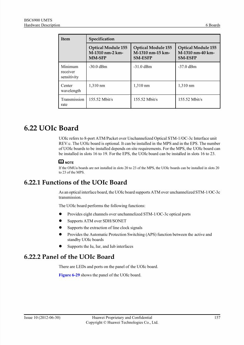
7/30/2019 BSC6900UMTS Hardware Description
http://slidepdf.com/reader/full/bsc6900umts-hardware-description 169/243
Item Specification
Optical Module 155M-1310 nm-2 km-MM-SFP
Optical Module 155M-1310 nm-15 km-SM-ESFP
Optical Module 155M-1310 nm-40 km-SM-ESFP
Minimum
receiver
sensitivity
-30.0 dBm -31.0 dBm -37.0 dBm
Center
wavelength
1,310 nm 1,310 nm 1,310 nm
Transmission
rate
155.52 Mbit/s 155.52 Mbit/s 155.52 Mbit/s
6.22 UOIc Board
UOIc refers to 8-port ATM/Packet over Unchannelized Optical STM-1/OC-3c Interface unit
REV:c. The UOIc board is optional. It can be installed in the MPS and in the EPS. The number
of UOIc boards to be installed depends on site requirements. For the MPS, the UOIc board can
be installed in slots 16 to 19. For the EPS, the UOIc board can be installed in slots 16 to 23.
NOTE
If the OMUa boards are not installed in slots 20 to 23 of the MPS, the UOIc boards can be installed in slots 20
to 23 of the MPS.
6.22.1 Functions of the UOIc BoardAs an optical interface board, the UOIc board supports ATM over unchannelized STM-1/OC-3c
transmission.
The UOIc board performs the following functions:
l Provides eight channels over unchannelized STM-1/OC-3c optical ports
l Supports ATM over SDH/SONET
l Supports the extraction of line clock signals
l Provides the Automatic Protection Switching (APS) function between the active and
standby UOIc boardsl Supports the Iu, Iur, and Iub interfaces
6.22.2 Panel of the UOIc Board
There are LEDs and ports on the panel of the UOIc board.
Figure 6-29 shows the panel of the UOIc board.
BSC6900 UMTS
Hardware Description 6 Boards
Issue 10 (2012-06-30) Huawei Proprietary and Confidential
Copyright © Huawei Technologies Co., Ltd.
157

7/30/2019 BSC6900UMTS Hardware Description
http://slidepdf.com/reader/full/bsc6900umts-hardware-description 170/243
Figure 6-29 Panel of the UOIc board
6.22.3 LEDs on the UOIc Board
There are four types of LEDs on the UOIc board: RUN, ALM, ACT, and LOS.
Table 6-86 describes the LEDs on the UOIc board.
Table 6-86 LEDs on the UOIc board
LED Color
Status Description
RUN Gree
n
ON for 1s and OFF for 1s The board is functional.
ON for 0.125s and OFF for
0.125s
The board is in loading state.
BSC6900 UMTS
Hardware Description 6 Boards
Issue 10 (2012-06-30) Huawei Proprietary and Confidential
Copyright © Huawei Technologies Co., Ltd.
158
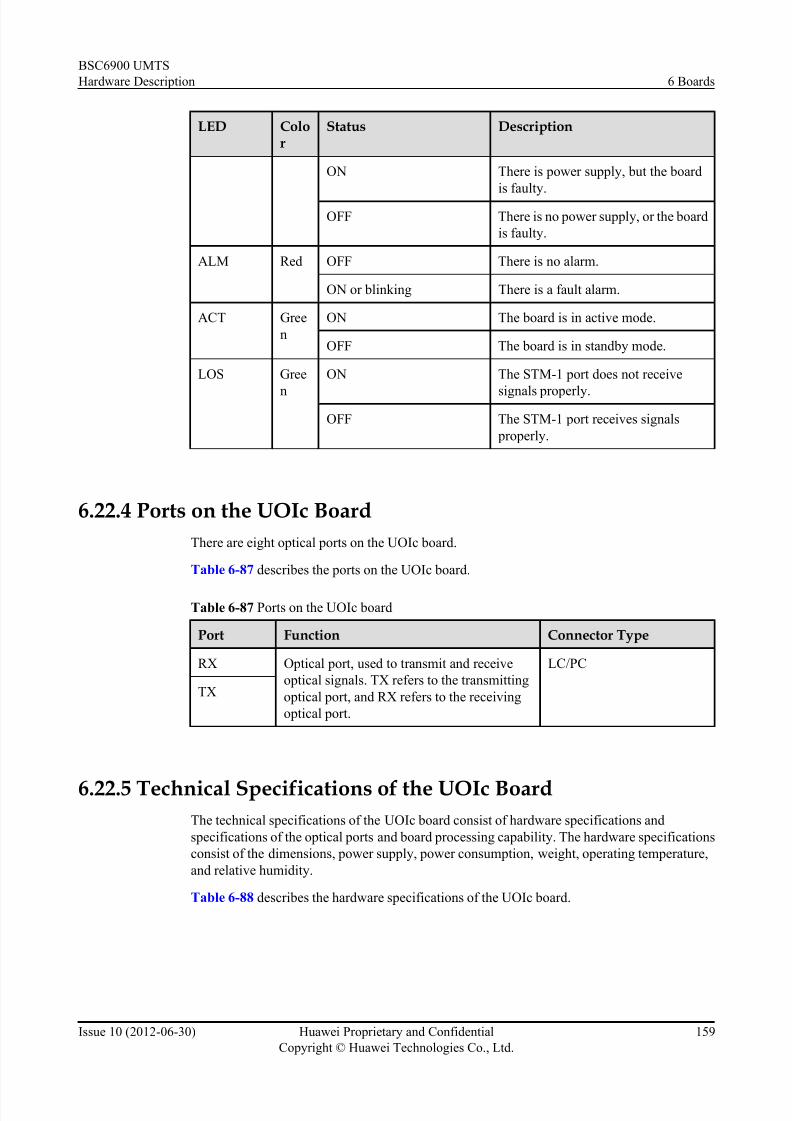
7/30/2019 BSC6900UMTS Hardware Description
http://slidepdf.com/reader/full/bsc6900umts-hardware-description 171/243
LED Color
Status Description
ON There is power supply, but the board
is faulty.
OFF There is no power supply, or the board
is faulty.
ALM Red OFF There is no alarm.
ON or blinking There is a fault alarm.
ACT Gree
n
ON The board is in active mode.
OFF The board is in standby mode.
LOS Gree
n
ON The STM-1 port does not receive
signals properly.
OFF The STM-1 port receives signals
properly.
6.22.4 Ports on the UOIc Board
There are eight optical ports on the UOIc board.
Table 6-87 describes the ports on the UOIc board.
Table 6-87 Ports on the UOIc board
Port Function Connector Type
RX Optical port, used to transmit and receive
optical signals. TX refers to the transmitting
optical port, and RX refers to the receiving
optical port.
LC/PC
TX
6.22.5 Technical Specifications of the UOIc BoardThe technical specifications of the UOIc board consist of hardware specifications and
specifications of the optical ports and board processing capability. The hardware specifications
consist of the dimensions, power supply, power consumption, weight, operating temperature,
and relative humidity.
Table 6-88 describes the hardware specifications of the UOIc board.
BSC6900 UMTS
Hardware Description 6 Boards
Issue 10 (2012-06-30) Huawei Proprietary and Confidential
Copyright © Huawei Technologies Co., Ltd.
159

7/30/2019 BSC6900UMTS Hardware Description
http://slidepdf.com/reader/full/bsc6900umts-hardware-description 172/243
Table 6-88 Hardware specifications of the UOIc board
Item Specification
Dimensions 248 mm x 32.3mm x 395.4 mm
Power supply Two -48 V DC working in active/standby mode. The backplane of the
subrack is responsible for the power supply.
Power consumption 86.52 W
Weight 1.50 kg
Operating
temperature (long-
term)
0°C to 45°C
Operating
temperature (short-
term)
-5°C to +55°C
Relative humidity
(long-term)
5% to 85%
Relative humidity
(short-term)
5% to 95%
Table 6-89 describes the specifications of the board processing capability.
Table 6-89 Specifications of the board processing capability
Item Specification
Number of channel identifiers(CIDs) 79,000
Session setup/release times 3,000/s
Iub Number of NodeBs 500
Speech service in the CS domain 18,000 Erlang
Data service in the CS domain 9,000 Erlang
Maximum payload throughput (UL) 800 Mbit/s
Maximum payload throughput (DL) 800 Mbit/s
Maximum payload throughput (UL
+DL)
800 Mbit/s
Iur Speech service in the CS domain 18,000 Erlang
Data service in the CS domain 9,000 Erlang
Maximum payload throughput (UL) 800 Mbit/s
Maximum payload throughput (DL) 800 Mbit/s
BSC6900 UMTS
Hardware Description 6 Boards
Issue 10 (2012-06-30) Huawei Proprietary and Confidential
Copyright © Huawei Technologies Co., Ltd.
160

7/30/2019 BSC6900UMTS Hardware Description
http://slidepdf.com/reader/full/bsc6900umts-hardware-description 173/243
Item Specification
Maximum payload throughput (UL
+DL)
800 Mbit/s
Iu-CS Speech service in the CS domain 18,000 Erlang
Data service in the CS domain 9,000 Erlang
Iu-PS Maximum payload throughput (UL) 900 Mbit/s
Maximum payload throughput (DL) 900 Mbit/s
Maximum payload throughput (UL
+DL)
1,800 Mbit/s
NOTE
l The specifications described in the preceding table apply to boards in active/standby mode. If a board
is configured in independent mode, the specifications cannot be reached.
l The preceding specifications are the maximum capability regarding the corresponding service.
l The data service in the CS domain indicates the 64 kbit/s video phone service.
l The number of session setup/release times indicates the signaling processing capacity of an Iub/Iu/Iur-
interface board.
l The throughput specifications are based on the conditions of UL 64 kbit/s and DL 384 kbit/s.
Table 6-90 describes the specifications of the optical ports on the UOIc board.
Table 6-90 Specifications of the optical ports on the UOIc board
Item Specification
Optical Module 155M-1310 nm-2 km-MM-SFP
Optical Module 155M-1310 nm-15 km-SM-ESFP
Optical Module 155M-1310 nm-40 km-SM-ESFP
Mode Multi-mode Single mode Single mode
Type LC/PC LC/PC LC/PC
Maximum
opticaltransmission
distance
2 km 15 km 40 km
Maximum
output optical
power
-14.0 dBm -8.0 dBm 0.0 dBm
Minimum
output optical
power
-19.0 dBm -15.0 dBm -5.0 dBm
BSC6900 UMTS
Hardware Description 6 Boards
Issue 10 (2012-06-30) Huawei Proprietary and Confidential
Copyright © Huawei Technologies Co., Ltd.
161

7/30/2019 BSC6900UMTS Hardware Description
http://slidepdf.com/reader/full/bsc6900umts-hardware-description 174/243
Item Specification
Optical Module 155M-1310 nm-2 km-MM-SFP
Optical Module 155M-1310 nm-15 km-SM-ESFP
Optical Module 155M-1310 nm-40 km-SM-ESFP
Minimum
receiver
sensitivity
-30.0 dBm -31.0 dBm -37.0 dBm
Center
wavelength
1,310 nm 1,310 nm 1,310 nm
Transmission
rate
155.52 Mbit/s 155.52 Mbit/s 155.52 Mbit/s
BSC6900 UMTS
Hardware Description 6 Boards
Issue 10 (2012-06-30) Huawei Proprietary and Confidential
Copyright © Huawei Technologies Co., Ltd.
162

7/30/2019 BSC6900UMTS Hardware Description
http://slidepdf.com/reader/full/bsc6900umts-hardware-description 175/243
7 Cables
About This Chapter
This chapter describes all the cables used inside and outside the BSC6900 cabinet.
7.1 Power Ca bles
The power ca bles are mandatory and are of two categories, that is, external power cables and
internal power cables. The power cables are the -48 V power cables and the RTN power cables.
7.2 PGND Cables
The PGND cables consist of external PGND cable, inter-cabinet PGND cables, PGND cable for
the power distribution box, PGND cables for the subrack, PGND cable for the independent fan
subrack, and PGND cables for the cabinet door. The PGND cable is mandatory.
7.3 Optical Cable
The optical cable is optional in the BSC6900. It is used to connect the optical interface board to
the Optical Distribution Frame (ODF) or other NEs. The number of optical cables to be installed
depends on the site requirements.
7.4 Optical S plitter/Combiner
The optical s plitter/combiner is optional in the BSC6900. A maximum of 48 optical splitters/
combiners can be installed in a subrack to combine two inputs of optical signals into one or split
one input into two.
7.5 75-ohm Coaxial Cable
The 75-ohm coaxial cable is a type of trunk cable. It is optional. The number of 75-ohm coaxial
cables to be installed depends on the site requirements. This cable connects the active/standby
AEUa/PEUa board to the Digital Distribution Frame (DDF) or other NEs and transmits E1 trunk
signals.
7.6 Active/Standby 75-ohm Coaxial Cable
The active/standby 75-ohm coaxial cable is a type of E1/T1 cable. It is optional. The number of
active/standby 75-ohm coaxial cables to be installed depends on site requirements. This cable
connects the active and standby AEUa/PEUa boards to the DDF or other NEs and transmits E1
signals.
7.7 120-ohm Twisted Pair Cable
BSC6900 UMTS
Hardware Description 7 Cables
Issue 10 (2012-06-30) Huawei Proprietary and Confidential
Copyright © Huawei Technologies Co., Ltd.
163

7/30/2019 BSC6900UMTS Hardware Description
http://slidepdf.com/reader/full/bsc6900umts-hardware-description 176/243

7/30/2019 BSC6900UMTS Hardware Description
http://slidepdf.com/reader/full/bsc6900umts-hardware-description 177/243
7.1 Power Cables
The power cables are mandatory and are of two categories, that is, external power cables and
internal power cables. The power cables are the -48 V power cables and the RTN power cables.
Description About Power Cables
The external power cables connect the Power Distribution Frame (PDF) to the power distribution
box at the top of the cabinet. The external power cables need to be installed on site. The internal
power cables connect the power distribution box to the modules inside the cabinet. The internal
power cables are installed before the cabinet is delivered.
Table 7-1 describes the external power cables for the N68E-21-N cabinet. Table 7-2 describes
the external power cables for the N68E-22 cabinet.
Table 7-1 External power cables for the N68E-21-N cabinet
CableName
Color Cross-SectionalArea
mm2
Connector Type 1/ InstallationPosition 1
ConnectorType 2/ InstallationPosition 2
Quantity
Externa
l -48 V
power
cable
Blue 25/35 2-hole JG
terminal/-48 V DC
input port on the
power distribution
box
OT terminal/-48
V DC output
port on the PDF
Four per
cabinet
Externa
l RTN
power
cable
Black 25/35 2-hole JG
terminal/-48 V DC
input port on the
power distribution
box
OT terminal/-48
V DC output
port on the PDF
Four per
cabinet
Table 7-2 External power cables for the N68E-22 cabinet
CableName
Color Cross-SectionalArea
mm2
Connector Type 1/ InstallationPosition 1
ConnectorType 2/ InstallationPosition 2
Quantity
Externa
l -48 V
power
cable
Blue 25/35 OT terminal/-48 V
DC input port on the
power distribution
box
OT
terminal/-48 V
DC output port
on the PDF
Four per
cabinet
BSC6900 UMTS
Hardware Description 7 Cables
Issue 10 (2012-06-30) Huawei Proprietary and Confidential
Copyright © Huawei Technologies Co., Ltd.
165

7/30/2019 BSC6900UMTS Hardware Description
http://slidepdf.com/reader/full/bsc6900umts-hardware-description 178/243
CableName
Color Cross-SectionalArea
mm2
Connector Type 1/ InstallationPosition 1
ConnectorType 2/ InstallationPosition 2
Quantity
Externa
l RTN
power
cable
Black 25/35 OT terminal/-48 V
DC input port on the
power distribution
box
OT
terminal/-48 V
DC output port
on the PDF
Four per
cabinet
NOTE
The cables delivered to different countries and regions are different in color and appearance. If engineers
are to purchase the cables in the local area, ensure that the cables purchased meet the local specifications.
The connectors of the internal power cables for the N68E-22 cabinet are the same as those for
the N68E-21-N cabinet. Table 7-3 describes the internal power cables.
Table 7-3 Internal power cables (1)
CableName
Color Cross-SectionalArea
mm2
Connector Type 1/ InstallationPosition 1
ConnectorType 2/ InstallationPosition 2
Quantity
Internal
-48 VDC
power
cable
Blue 10 OT terminal/-48 V
DC output port onthe power
distribution box
OT
terminal/-48 VDC output port
on the subrack
Two per
subrack
Internal
RTN
power
cable
Black 10 OT terminal/-48 V
DC output port on
the power
distribution box
OT
terminal/-48 V
DC output port
on the subrack
Two per
subrack
Table 7-4 Internal power cables (2)
CableName
Color Cross-SectionalArea
mm2
ConnectorType 1/ InstallationPosition 1
ConnectorType 2/ InstallationPosition 2
Quantity
Internal
-48 V
DC
power
cable
Blue 2 OT
terminal/-48 V
DC input port
on the power
distribution
box
D-type
connector/
power input
port on the
independent
fan subrack
Two per subrack
BSC6900 UMTS
Hardware Description 7 Cables
Issue 10 (2012-06-30) Huawei Proprietary and Confidential
Copyright © Huawei Technologies Co., Ltd.
166

7/30/2019 BSC6900UMTS Hardware Description
http://slidepdf.com/reader/full/bsc6900umts-hardware-description 179/243
CableName
Color Cross-SectionalArea
mm2
ConnectorType 1/ InstallationPosition 1
ConnectorType 2/ InstallationPosition 2
Quantity
Internal
RTN
power
cable
Black 2 OT
terminal/-48 V
DC input port
on the power
distribution
box
D-type
connector/
power input
port on the
independent
fan subrack
Two per subrack
Appearance
Figure 7-1 shows the internal power cable for subracks.
Figure 7-1 Internal power cable for subracks
(1) OT terminal
Figure 7-2 shows the internal power cable for the independent fan subrack.
Figure 7-2 Internal power cable for the independent fan subrack
Figure 7-3 shows the external power cable for the N68E-22 cabinet.
Figure 7-3 External power cable for the N68E-22 cabinet
(1) OT terminal
Figure 7-4 shows the external power cable for the N68E-21-N cabinet.
BSC6900 UMTS
Hardware Description 7 Cables
Issue 10 (2012-06-30) Huawei Proprietary and Confidential
Copyright © Huawei Technologies Co., Ltd.
167

7/30/2019 BSC6900UMTS Hardware Description
http://slidepdf.com/reader/full/bsc6900umts-hardware-description 180/243
Figure 7-4 External power cable for the N68E-21-N cabinet
(1) OT terminal (2) 2-hole JG terminal
7.2 PGND Cables
The PGND cables consist of external PGND cable, inter-cabinet PGND cables, PGND cable for
the power distribution box, PGND cables for the subrack, PGND cable for the independent fan
subrack, and PGND cables for the cabinet door. The PGND cable is mandatory.
Each cabinet must be configured with one external PGND cable. When the cabinets are
combined, three inter-cabinet PGND cables must be installed between every two adjacent
cabinets. Other PGND cables are already installed in the cabinet before delivery.
Table 7-5 describes the PGND cables.
Table 7-5 PGND cables
CableName
Color Cross-SectionalArea
mm2
Connector Type1/
InstallationPosition1
ConnectorType 2/ Installation
Position 2
Quantity
External
PGND
cable
Green and
yellow
25/35 OT
terminal/
Groundin
g bolt at
the top
rear of
each
cabinet
OT terminal/
PGND output
port on the PDF
One per
cabinet
Inter-
cabinet
PGND
cable
Green and
yellow
6 OT
terminal/
PGND
busbar of
each
cabinet
OT terminal/
PGND busbar of
each cabinet
Three
between
every two
adjacent
cabinets
BSC6900 UMTS
Hardware Description 7 Cables
Issue 10 (2012-06-30) Huawei Proprietary and Confidential
Copyright © Huawei Technologies Co., Ltd.
168

7/30/2019 BSC6900UMTS Hardware Description
http://slidepdf.com/reader/full/bsc6900umts-hardware-description 181/243
CableName
Color Cross-SectionalArea
mm2
Connector Type1/ Installati
onPosition1
ConnectorType 2/ InstallationPosition 2
Quantity
PGND
cable for
the power
distributio
n box
Green and
yellow
6 OT
terminal/
PGND
busbar of
each
cabinet
OT terminal/Port
for PGND cable
on the power
distribution box
One per
power
distribution
box
PGND
cable for
the subrack
Green and
yellow
6 OT
terminal/
PGND
busbar of
each
cabinet
OT terminal/Port
for the PGND
cable on the
subrack
Two per
subrack
PGND
cable for
the cabinet
door
Green and
yellow
6 OT
terminal/
Groundin
g bolt on
the base
OT terminal/
Grounding bolt
on the cabinet
door
Eight per
cabinet
PGND
cable for the
independe
nt fan
subrack
Green and
yellow
6 OT
terminal/PGND
busbar of
each
cabinet
OT terminal/
Grounding pointof the
independent fan
subrack
One per
independentfan subrack
The PGND cable for the independent fan subrack is different from the other PGND cables for
the BSC6900. Figure 7-5 shows the PGND cable for the independent fan subrack. Figure 7-6
shows the other PGND cables.
Figure 7-5 PGND cable for the independent fan subrack
Figure 7-6 Other PGND cables
BSC6900 UMTS
Hardware Description 7 Cables
Issue 10 (2012-06-30) Huawei Proprietary and Confidential
Copyright © Huawei Technologies Co., Ltd.
169

7/30/2019 BSC6900UMTS Hardware Description
http://slidepdf.com/reader/full/bsc6900umts-hardware-description 182/243
7.3 Optical Cable
The optical cable is optional in the BSC6900. It is used to connect the optical interface board tothe Optical Distribution Frame (ODF) or other NEs. The number of optical cables to be installed
depends on the site requirements.
Classification of the Optical Cable
According to the types of optical connectors at both ends of the cable, the optical cable can be
classified into the following types:
l LC/PC-LC/PC single-mode/multi-mode optical cable
l LC/PC-FC/PC single-mode/multi-mode optical cable
l LC/PC-SC/PC single-mode/multi-mode optical cable
NOTE
l In actual installation, the LC/PC optical connector at one end of the cable is connected to the optical
interface board in the BSC6900, and the connector type at the other end of the cable depends on site
requirements.
l The LC/PC-LC/PC single-mode/multi-mode optical cable connects the optical interface board to the
ODF or other NEs or connects the optical interface boards.
l In practice, two optical cables form a pair. Both ends of each cable in the pair are attached with
temporary labels. If one end of the cable is connected to the TX port, the other end should be connected
to the RX port.
CAUTION
The TX end and RX end of each optical cable must be connected correctly. Otherwise, the optical
signals cannot be received or transmitted.
BSC6900 Optical Cables
Table 7-6 shows the optical cables used in the BSC6900.
Table 7-6 BSC6900 optical cables
Optical Cable Type Appearance
LC/PC-LC/PC single-
mode/multi-mode
LC/PC-FC/PC single-
mode/multi-mode
LC/PC-SC/PC single-
mode/multi-mode
BSC6900 UMTS
Hardware Description 7 Cables
Issue 10 (2012-06-30) Huawei Proprietary and Confidential
Copyright © Huawei Technologies Co., Ltd.
170

7/30/2019 BSC6900UMTS Hardware Description
http://slidepdf.com/reader/full/bsc6900umts-hardware-description 183/243
Installation
The optical cable has an LC/PC connector at one end connected to the optical interface board
in the BSC6900. The other end of the optical cable can use an LC/PC connector, SC/PC
connector, or FC/PC connector as required. Figure 7-7 shows the installation positions of the
optical cable.
Figure 7-7 Installation positions of the optical cable
7.4 Optical Splitter/Combiner
The optical splitter/combiner is optional in the BSC6900. A maximum of 48 optical splitters/
combiners can be installed in a subrack to combine two inputs of optical signals into one or split
one input into two.
FunctionThe optical splitter/combiner splits or combines optical signals.
Figure 7-8 shows the operating principle of an optical combiner.
Figure 7-8 Operating principle of an optical combiner
Figure 7-9 shows the operating principle of an optical splitter.
BSC6900 UMTS
Hardware Description 7 Cables
Issue 10 (2012-06-30) Huawei Proprietary and Confidential
Copyright © Huawei Technologies Co., Ltd.
171

7/30/2019 BSC6900UMTS Hardware Description
http://slidepdf.com/reader/full/bsc6900umts-hardware-description 184/243

7/30/2019 BSC6900UMTS Hardware Description
http://slidepdf.com/reader/full/bsc6900umts-hardware-description 185/243
CAUTION
Only the AOUa, UOIa, AOUc, POUc, and UOIc boards can be connected to an optical splitter/
combiner.The optical splitter/combiner cannot be used to solve any of the following problems:
l The active and standby optical ports on BSC6900 interface boards are operational. When the
transmission on the TX optical fiber for the active optical port is interrupted, the BSC6900
reports a Multiplex Section (MS) Remote Defect Indication (RDI) alarm on the active and
standby optical ports. An automatic switchover, however, is not triggered between the active
and standby optical ports.
l The active and standby optical ports on BSC6900 interface boards are operational. The
transmission is interrupted on the optical fiber between the optical splitter/combiner and the
TX port on the peer equipment, and the BSC6900 reports a MS RDI alarm on the active and
standby optical ports. An automatic switchover, however, is not triggered between the active
and standby optical ports.
l The active and standby optical ports on BSC6900 interface boards are operational. The
transmission is interrupted on the optical fiber between the optical splitter/combiner and the
RX port on the peer equipment, and the BSC6900 reports a Loss of Signal (LOS) alarm on
the active and standby optical ports. An automatic switchover, however, is not triggered
between the active and standby optical ports.
Installation
Figure 7-11 shows the installation positions of optical splitters/combiners.
Figure 7-11 Installation positions of optical splitters/combiners
BSC6900 UMTS
Hardware Description 7 Cables
Issue 10 (2012-06-30) Huawei Proprietary and Confidential
Copyright © Huawei Technologies Co., Ltd.
173

7/30/2019 BSC6900UMTS Hardware Description
http://slidepdf.com/reader/full/bsc6900umts-hardware-description 186/243
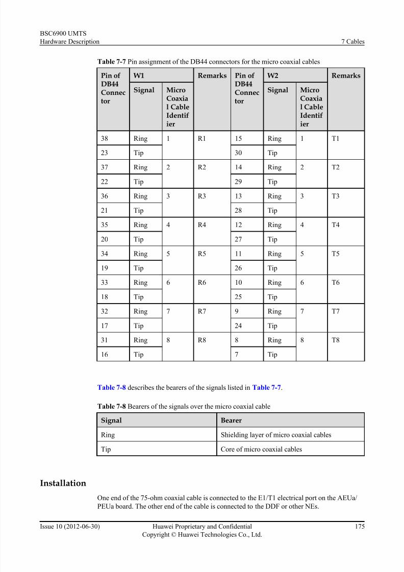
7/30/2019 BSC6900UMTS Hardware Description
http://slidepdf.com/reader/full/bsc6900umts-hardware-description 187/243
Table 7-7 Pin assignment of the DB44 connectors for the micro coaxial cables
Pin ofDB44Connec
tor
W1 Remarks Pin ofDB44Connec
tor
W2 Remarks
Signal Micro
Coaxial CableIdentifier
Signal Micro
Coaxial CableIdentifier
38 Ring 1 R1 15 Ring 1 T1
23 Tip 30 Tip
37 Ring 2 R2 14 Ring 2 T2
22 Tip 29 Tip
36 Ring 3 R3 13 Ring 3 T3
21 Tip 28 Tip
35 Ring 4 R4 12 Ring 4 T4
20 Tip 27 Tip
34 Ring 5 R5 11 Ring 5 T5
19 Tip 26 Tip
33 Ring 6 R6 10 Ring 6 T6
18 Tip 25 Tip
32 Ring 7 R7 9 Ring 7 T7
17 Tip 24 Tip
31 Ring 8 R8 8 Ring 8 T8
16 Tip 7 Tip
Table 7-8 describes the bearers of the signals listed in Table 7-7.
Table 7-8 Bearers of the signals over the micro coaxial cable
Signal Bearer
Ring Shielding layer of micro coaxial cables
Tip Core of micro coaxial cables
Installation
One end of the 75-ohm coaxial cable is connected to the E1/T1 electrical port on the AEUa/PEUa board. The other end of the cable is connected to the DDF or other NEs.
BSC6900 UMTS
Hardware Description 7 Cables
Issue 10 (2012-06-30) Huawei Proprietary and Confidential
Copyright © Huawei Technologies Co., Ltd.
175

7/30/2019 BSC6900UMTS Hardware Description
http://slidepdf.com/reader/full/bsc6900umts-hardware-description 188/243

7/30/2019 BSC6900UMTS Hardware Description
http://slidepdf.com/reader/full/bsc6900umts-hardware-description 189/243
Table 7-9 Pin assignment of the DB44 connectors for W3 and W4
X1 W3 Remarks
X1 W4 Remarks
Pin of
DB44Connector
Signal Micro
CoaxialCableIdentifier
Pin of
DB44Connector
Signal Micro
CoaxialCableIdentifier
38 Ring 1 R1 15 Ring 1 T1
23 Tip 30 Tip
37 Ring 2 R2 14 Ring 2 T2
22 Tip 29 Tip
36 Ring 3 R3 13 Ring 3 T321 Tip 28 Tip
35 Ring 4 R4 12 Ring 4 T4
20 Tip 27 Tip
34 Ring 5 R5 11 Ring 5 T5
19 Tip 26 Tip
33 Ring 6 R6 10 Ring 6 T6
18 Tip 25 Tip
32 Ring 7 R7 9 Ring 7 T7
17 Tip 24 Tip
31 Ring 8 R8 8 Ring 8 T8
16 Tip 7 Tip
NOTE
In Table 7-9, T1 indicates the first-route E1 TX signal, and R1 indicates the first-route E1 RX signal.
Similarly, RN indicates the Nth-route E1 RX signal, and TN indicates the Nth-route E1 TX signal.
Table 7-10 describes the signals of the micro coaxial cables listed in Table 7-9.
Table 7-10 Bearers of the signals over the micro coaxial cable
Signal Bearer
Ring Shielding layer of coaxial cables
Tip Core of coaxial cables
BSC6900 UMTS
Hardware Description 7 Cables
Issue 10 (2012-06-30) Huawei Proprietary and Confidential
Copyright © Huawei Technologies Co., Ltd.
177

7/30/2019 BSC6900UMTS Hardware Description
http://slidepdf.com/reader/full/bsc6900umts-hardware-description 190/243

7/30/2019 BSC6900UMTS Hardware Description
http://slidepdf.com/reader/full/bsc6900umts-hardware-description 191/243
Figure 7-14 Installation positions of the active/standby 75-ohm coaxial cables
7.7 120-ohm Twisted Pair Cable
The 120-ohm twisted pair cable is a type of trunk cable. It is optional. The number of 120-ohm
twisted pair cables to be installed depends on the site requirements. This cable connects the
active/standby AEUa/PEUa board to the DDF or other NEs and transmits E1 signals.
AppearanceFigure 7-15 shows the 120-ohm twisted pair cable.
Figure 7-15 120-ohm twisted pair cable
(1) DB44 connector (2) Main label (identifying the code, version, and manufacturer of
the cable)
(3) Label (identifying a twisted pair cable) (4) Metal case of the DB44 connector
The 120-ohm twisted pair cable has a DB44 connector only at one end. You need to add aconnector to the other end according to the actual requirements.
BSC6900 UMTS
Hardware Description 7 Cables
Issue 10 (2012-06-30) Huawei Proprietary and Confidential
Copyright © Huawei Technologies Co., Ltd.
179

7/30/2019 BSC6900UMTS Hardware Description
http://slidepdf.com/reader/full/bsc6900umts-hardware-description 192/243
Pin Assignment
The outer shielding layer of the 120-ohm twisted pair cable is connected to the BSC6900 by the
metal case of the DB44 connector. Table 7-12 describes the pin assignment of the DB44
connector for the 120-ohm twisted pair cable.
Table 7-12 Pin assignment of the DB44 connector for the 120-ohm twisted pair cable
Pin ofDB44Connector
W1 Color Pin ofDB44Connector
W2 Color
Signal 120-OhmTwistedPairCableIdentifier
Signal 120-OhmTwistedPairCableIdentifier
38 Ring/R- R1 Blue 15 Ring/T- T1 Blue
23 Tip/R+ White 30 Tip/T+ White
37 Ring/R- R2 Orange 14 Ring/T- T2 Orange
22 Tip/R+ White 29 Tip/T+ White
36 Ring/R- R3 Green 13 Ring/T- T3 Green
21 Tip/R+ White 28 Tip/T+ White
35 Ring/R- R4 Brown 12 Ring/T- T4 Brown
20 Tip/R+ White 27 Tip/T+ White
34 Ring/R- R5 Grey 11 Ring/T- T5 Grey
19 Tip/R+ White 26 Tip/T+ White
33 Ring/R- R6 Blue 10 Ring/T- T6 Blue
18 Tip/R+ Red 25 Tip/T+ Red
32 Ring/R- R7 Orange 9 Ring/T- T7 Orange
17 Tip/R+ Red 24 Tip/T+ Red
31 Ring/R- R8 Green 8 Ring/T- T8 Green
16 Tip/R+ Red 7 Tip/T+ Red
Table 7-13 describes the bearers of the signals listed in Table 7-12.
BSC6900 UMTS
Hardware Description 7 Cables
Issue 10 (2012-06-30) Huawei Proprietary and Confidential
Copyright © Huawei Technologies Co., Ltd.
180

7/30/2019 BSC6900UMTS Hardware Description
http://slidepdf.com/reader/full/bsc6900umts-hardware-description 193/243
Table 7-13 Bearers of the signals over the twisted pair cable
Signal Bearer
Ring/R- One core of the twisted pair cable for receiving E1/T1
signals
Tip/R+ The other core of the twisted pair cable for receiving E1/T1
signals
Ring/T- One core of the twisted pair cable for transmitting E1/T1
signals
Tip/T+ The other core of the twisted pair cable for transmitting E1/
T1 signals
Installation
One end of the 120-ohm twisted pair cable is connected to the E1/T1 electrical port on the AEUa/
PEUa board. The other end of the cable is connected to the DDF or other NEs.
7.8 Active/Standby 120-ohm Twisted Pair Cable
The active/standby 120-ohm twisted pair cable is a type of E1/T1 cable. It is optional. The
number of 120-ohm twisted pair cables to be installed depends on site requirements. This cable
connects the active and standby AEUa/PEUa boards to the DDF or other NEs and transmits E1/
T1 signals.
Appearance
Figure 7-16 shows the active/standby 120-ohm twisted pair cable.
Figure 7-16 Active/Standby 120-ohm twisted pair cable
(1) DB44 connector (2) Metal case of the DB44 connector
(3) Label 1 (identifying a twisted pair cable) (4) Main label (identifying the code, version, and manufacturer
of the cable)
(5) Label 2 (identifying a twisted pair cable)
BSC6900 UMTS
Hardware Description 7 Cables
Issue 10 (2012-06-30) Huawei Proprietary and Confidential
Copyright © Huawei Technologies Co., Ltd.
181

7/30/2019 BSC6900UMTS Hardware Description
http://slidepdf.com/reader/full/bsc6900umts-hardware-description 194/243
The active/standby 120-ohm twisted pair cable has two DB44 connectors only at one end. You
need to add connectors to the other end according to the actual requirements.
Table 7-14 and Table 7-16 describe the pin assignment of the DB44 connectors for the active/standby 120-ohm twisted pair cable.
Table 7-14 Pin assignment of the DB44 connectors for W3 and W4
X1 W3 Color X1 W4 Color
Pin ofDB44Connector
Signal Twisted PairCableIdentifier
Pin ofDB44Connector
Signal Twisted PairCableIdentifier
38 Ring/R- R1 Blue 15 Ring/R- T1 Blue
23 Tip/R+ White 30 Tip/R+ White
37 Ring/R- R2 Orange 14 Ring/R- T2 Orange
22 Tip/R+ White 29 Tip/R+ White
36 Ring/R- R3 Green 13 Ring/R- T3 Green
21 Tip/R+ White 28 Tip/R+ White
35 Ring/R- R4 Brown 12 Ring/R- T4 Brown
20 Tip/R+ White 27 Tip/R+ White
34 Ring/T- R5 Grey 11 Ring/T- T5 Grey
19 Tip/T+ White 26 Tip/T+ White
33 Ring/T- R6 Blue 10 Ring/T- T6 Blue
18 Tip/T+ Red 25 Tip/T+ Red
32 Ring/T- R7 Orange 9 Ring/T- T7 Orange
17 Tip/T+ Red 24 Tip/T+ Red
31 Ring/T- R8 Green 8 Ring/T- T8 Green
16 Tip/T+ Red 7 Tip/T+ Red
NOTE
In Table 7-14, R- and R+ stand for reception signals; T- and T+ stand for transmission signals.
Table 7-15 describes the bearers of the signals listed in Table 7-14.
BSC6900 UMTS
Hardware Description 7 Cables
Issue 10 (2012-06-30) Huawei Proprietary and Confidential
Copyright © Huawei Technologies Co., Ltd.
182

7/30/2019 BSC6900UMTS Hardware Description
http://slidepdf.com/reader/full/bsc6900umts-hardware-description 195/243
Table 7-15 Bearers of the signals over the twisted pair cable
Signal Bearer
Ring/R- One core of the twisted pair cable for transmitting E1/T1 signals
to the BSC6900
Tip/R+ The other core of the twisted pair cable for transmitting E1/T1
signals to the BSC6900
Ring/T- One core of the twisted pair cable for transmitting E1/T1 signals
from the BSC6900
Tip/T+ The other core of the twisted pair cable for transmitting E1/T1
signals from the BSC6900
Table 7-16 Pin assignment of the connectors for W1 and W2
Twisted Pair Cable W2 Remarks Twisted Pair Cable W1 Remarks
Pin of X1Connector
Pin of X2Connector
Pin of X1Connector
Pin of X2Connector
38 38 PAIR 15 15 PAIR
23 23 30 30
37 37 PAIR 14 14 PAIR
22 22 29 29
36 36 PAIR 13 13 PAIR
21 21 28 28
35 35 PAIR 12 12 PAIR
20 20 27 27
34 34 PAIR 11 11 PAIR
19 19 26 26
33 33 PAIR 10 10 PAIR
18 18 25 25
32 32 PAIR 9 9 PAIR
17 17 24 24
31 31 PAIR 8 8 PAIR
16 16 7 7
BSC6900 UMTS
Hardware Description 7 Cables
Issue 10 (2012-06-30) Huawei Proprietary and Confidential
Copyright © Huawei Technologies Co., Ltd.
183

7/30/2019 BSC6900UMTS Hardware Description
http://slidepdf.com/reader/full/bsc6900umts-hardware-description 196/243
NOTE
In Table 7-16, PAIR indicates a pair of twisted pair cables, and Braid indicates the outer shielding layer
of the twisted pair cable.
Installation
The two DB44 connectors at one end of the active/standby 120-ohm twisted pair cable are
connected to the active and standby AEUa/PEUa boards. The other end of the active/standby
120-ohm twisted pair cable is connected to the DDF in the equipment room and then to another
NE through transmission equipment. The other end of the active/standby 120-ohm twisted pair
cable can also be connected to another NE directly.
Figure 7-17 shows the installation positions of the active/standby 120-ohm twisted pair cables.
Figure 7-17 Installation positions of the active/standby 120-ohm twisted pair cables
7.9 BITS Clock Cable
The BITS clock cable is a type of clock signal cable. It is optional. The number of BITS clock
cables to be installed depends on site requirements. This cable transmits the BITS clock signals
to the GCUa/GCGa board in the MPS. According to the impedance of the signal cables, the
BITS clock signal cables are classified into 75-ohm coaxial clock cables and 120-ohm clock conversion cables.
Appearance
Figure 7-18 shows the 75-ohm coaxial clock cable.
BSC6900 UMTS
Hardware Description 7 Cables
Issue 10 (2012-06-30) Huawei Proprietary and Confidential
Copyright © Huawei Technologies Co., Ltd.
184

7/30/2019 BSC6900UMTS Hardware Description
http://slidepdf.com/reader/full/bsc6900umts-hardware-description 197/243
Figure 7-18 75-ohm coaxial clock cable
(1) SMB connector (2) Label
Figure 7-19 shows the 120-ohm clock conversion cable.
Figure 7-19 120-ohm clock conversion cable
(1) SMB connector 2Label
NOTE
The 120-ohm clock conversion cable has two SMB connectors at one end. Only one SMB connector is
used, and the other SMB connector is bound to the wire bushing by using cable ties. Pay attention to the
connection when using the 120-ohm clock conversion cable.
Installation
One end of the BITS clock signal cable is connected to the CLKIN0 or the CLKIN1 port on the
GCUa/GCGa board. The other end of the cable is connected to the BITS clock source.
Figure 7-20 shows the installation positions of the BITS clock signal cables.
BSC6900 UMTS
Hardware Description 7 Cables
Issue 10 (2012-06-30) Huawei Proprietary and Confidential
Copyright © Huawei Technologies Co., Ltd.
185

7/30/2019 BSC6900UMTS Hardware Description
http://slidepdf.com/reader/full/bsc6900umts-hardware-description 198/243
Figure 7-20 Installation positions of the BITS clock signal cables
7.10 Y-Shaped Clock Cable
The Y-shaped clock cable is a type of clock signal cables. It is optional. The number of Y-shaped
clock cables to be installed depends on the site requirements. This cable transmits the 8 kHz
clock signals from the GCUa/GCGa board in the MPS to the SCUa board in the EPS.
NOTE
The Y-shaped clock cable is not required if the BSC6900 is configured with only one MPS and no EPS.
Appearance
Figure 7-21 shows the Y-shaped clock cable.
BSC6900 UMTS
Hardware Description 7 Cables
Issue 10 (2012-06-30) Huawei Proprietary and Confidential
Copyright © Huawei Technologies Co., Ltd.
186
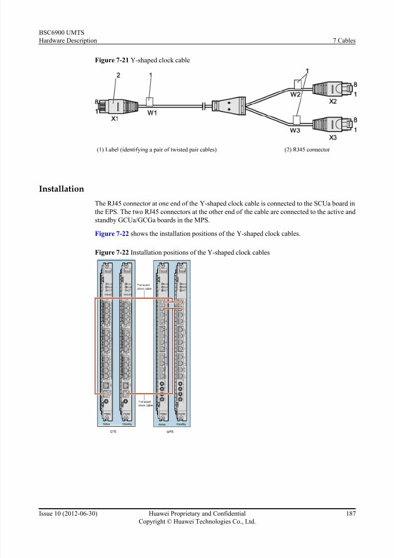
7/30/2019 BSC6900UMTS Hardware Description
http://slidepdf.com/reader/full/bsc6900umts-hardware-description 199/243
Figure 7-21 Y-shaped clock cable
(1) Label (identifying a pair of twisted pair cables) (2) RJ45 connector
Installation
The RJ45 connector at one end of the Y-shaped clock cable is connected to the SCUa board in
the EPS. The two RJ45 connectors at the other end of the cable are connected to the active and
standby GCUa/GCGa boards in the MPS.
Figure 7-22 shows the installation positions of the Y-shaped clock cables.
Figure 7-22 Installation positions of the Y-shaped clock cables
BSC6900 UMTS
Hardware Description 7 Cables
Issue 10 (2012-06-30) Huawei Proprietary and Confidential
Copyright © Huawei Technologies Co., Ltd.
187

7/30/2019 BSC6900UMTS Hardware Description
http://slidepdf.com/reader/full/bsc6900umts-hardware-description 200/243
7.11 Line Clock Signal Cable
The line clock signal cable is optional. Two to four line clock signal cables can be installed to
transmit the line clock signals which are received from the interface board of the EPS to the
GCUa/GCGa board.
NOTE
When the interface board providing line clock signals is located in the MPS, the line clock signals are sent
to the GCUa/GCGa board through the backplane of the subrack. In this case, the line clock signal cable is
not required.
Appearance
Figure 7-23 shows the line clock signal cable.
Figure 7-23 Line clock signal cable
(1) SMB connector
InstallationOne end of the line clock signal cable is connected to the 2M0 or the 2M1 port on the interface
board. The other end of the signal cable is connected to the CLKIN0 or the CLKIN1 port on the
GCUa/GCGa board.
7.12 Straight-Through Cable
The straight-through cable is of two types: the shielded straight-through cable and the unshielded
straight-through cable. The unshielded straight-through cable is used to connect the SCUa boards
in different subracks. The shielded straight-through cable is used to connect the FG2a/OMUa/
FG2c board to other devices. The number of straight-through cables to be installed depends onthe site requirements.
Appearance
Figure 7-24 shows the shielded straight-through cable.
BSC6900 UMTS
Hardware Description 7 Cables
Issue 10 (2012-06-30) Huawei Proprietary and Confidential
Copyright © Huawei Technologies Co., Ltd.
188

7/30/2019 BSC6900UMTS Hardware Description
http://slidepdf.com/reader/full/bsc6900umts-hardware-description 201/243
Figure 7-24 Shielded straight-through cable
NOTE
X1 and X2 are shielded RJ45 connectors at the two ends of the shielded straight-through cable.
Figure 7-25 shows the unshielded straight-through cable.
Figure 7-25 Unshielded straight-through cable
NOTE
X1 and X2 are unshielded RJ45 connectors at the two ends of the unshielded straight-through cable.
Pin Assignment
Table 7-17 describes the pins in the RJ45 connectors at the two ends of the shielded straight-
through cable and the unshielded straight-through cable.
BSC6900 UMTS
Hardware Description 7 Cables
Issue 10 (2012-06-30) Huawei Proprietary and Confidential
Copyright © Huawei Technologies Co., Ltd.
189

7/30/2019 BSC6900UMTS Hardware Description
http://slidepdf.com/reader/full/bsc6900umts-hardware-description 202/243
Table 7-17 Pins of the straight-through cable
X1 End Wire Color X2 End Wire Color
X1-1 White and orange X2-1 White and orange
X1-2 Orange X2-2 Orange
X1-3 White and green X2-3 White and green
X1-4 Blue X2-4 Blue
X1-5 White and blue X2-5 White and blue
X1-6 Green X2-6 Green
X1-7 White and brown X2-7 White and brown
X1-8 Brown X2-8 Brown
Installation
l When the unshielded straight-through cable is used to connect the SCUa boards in different
subracks, the RJ45 connectors at the two ends of the cable are connected to the SCUa boards
that are located in different subracks, as shown in Figure 7-26.
Figure 7-26 Installation positions of the unshielded straight-through cables between the
SCUa boards in different subracks
l When the shielded straight-through cable is used to connect the OMUa board to other
devices, the RJ45 connector at one end of the cable is connected to ETH0 or ETH1 on the
OMUa board, and the RJ45 connector at the other end of the cable is connected to the
Ethernet port on the other devices.
l
When the shielded straight-through cable is used to connect the FG2a/FG2c board to other devices, the RJ45 connector at one end of the cable is connected to an Ethernet port on the
BSC6900 UMTS
Hardware Description 7 Cables
Issue 10 (2012-06-30) Huawei Proprietary and Confidential
Copyright © Huawei Technologies Co., Ltd.
190

7/30/2019 BSC6900UMTS Hardware Description
http://slidepdf.com/reader/full/bsc6900umts-hardware-description 203/243
FG2a/FG2c board, and the RJ45 connector at the other end of the cable is connected to the
Ethernet port on the other devices.
7.13 Monitoring Signal Cable for the Independent FanSubrack
The monitoring signal cable for the independent fan subrack transmits monitoring signals to the
service subracks.
Appearance
Figure 7-27 shows the monitoring signal cable for the independent fan subrack.
Figure 7-27 Monitoring signal cable for the independent fan subrack
The monitoring signal cable for the independent fan subrack has a DB9 connector at one endand a DB15 connector at the other end.
Table 7-18 describes the pins of the monitoring signal cable for the independent fan subrack.
Table 7-18 Pins of the monitoring signal cable for the independent fan subrack
Start End Description Remarks
X1.1 X2.7 Tx+ Twisted pair
X1.2 X2.6 Tx-
X1.3 X2.3 Rx+ Twisted pair
X1.4 X2.2 Rx-
X1.5 X2.5 GND -
X1.SHELL X2.SHELL - X1.SHELL is
connected to
X2.SHELL through
the shielding layer.
Table 7-19 describes the signals listed in Table 7-18.
BSC6900 UMTS
Hardware Description 7 Cables
Issue 10 (2012-06-30) Huawei Proprietary and Confidential
Copyright © Huawei Technologies Co., Ltd.
191

7/30/2019 BSC6900UMTS Hardware Description
http://slidepdf.com/reader/full/bsc6900umts-hardware-description 204/243
Table 7-19 Signals
Signal Signal Description
Tx+ Positive phase signal transmitted
Tx- Negative phase signal transmitted
Rx+ Positive phase signal received
Rx- Negative phase signal received
Installation
The DB15 connector at one end of the monitoring signal cable for the independent fan subrack
is connected to the MONITOR 0 port on the independent fan subrack. The DB9 connector at
the other end of the cable is connected to the Monitor port on the bottom subrack.
NOTE
When a cabinet is configured with multiple subracks, you should configure the subracks from bottom to
top. Therefore, the monitoring signal cable for the independent fan subrack is always connected to the
bottom subrack in the cabinet.
7.14 Alarm Box Signal Cable
The alarm box signal cable is a type of signal cable available in different specifications. You
can choose one based on actual requirements. The alarm box signal cable is used to send the
alarm information to the alarm box for audible and visual display.
Appearance
The connectors of the alarm box signal cable are of two types: DB9 and DB25. The actual type
must be consistent with that in the Site Survey Report. The following takes an alarm box signal
cable with the DB9 connector as an example.
Figure 7-28 shows an alarm box signal cable.
Figure 7-28 Alarm box signal cable
Pin Assignment
Table 7-20 describes the pins of the alarm box signal cable.
BSC6900 UMTS
Hardware Description 7 Cables
Issue 10 (2012-06-30) Huawei Proprietary and Confidential
Copyright © Huawei Technologies Co., Ltd.
192
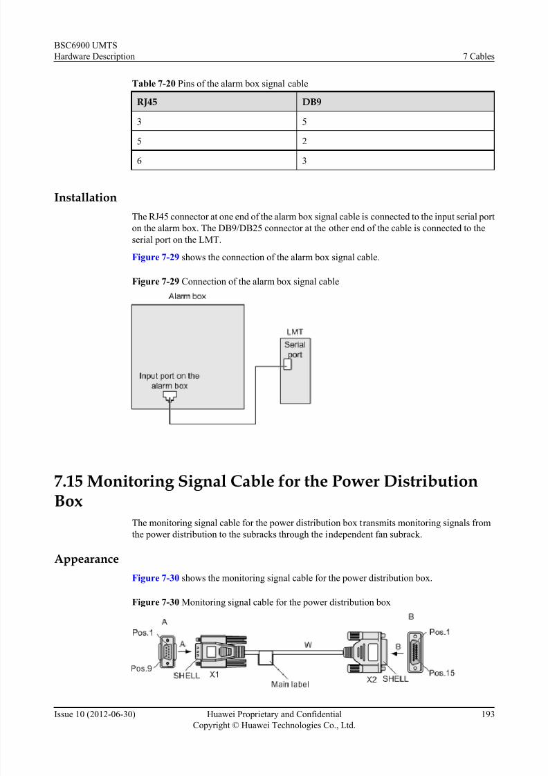
7/30/2019 BSC6900UMTS Hardware Description
http://slidepdf.com/reader/full/bsc6900umts-hardware-description 205/243
Table 7-20 Pins of the alarm box signal cable
RJ45 DB9
3 5
5 2
6 3
Installation
The RJ45 connector at one end of the alarm box signal cable is connected to the input serial port
on the alarm box. The DB9/DB25 connector at the other end of the cable is connected to the
serial port on the LMT.
Figure 7-29 shows the connection of the alarm box signal cable.
Figure 7-29 Connection of the alarm box signal cable
7.15 Monitoring Signal Cable for the Power DistributionBox
The monitoring signal cable for the power distribution box transmits monitoring signals from
the power distribution to the subracks through the independent fan subrack.
Appearance
Figure 7-30 shows the monitoring signal cable for the power distribution box.
Figure 7-30 Monitoring signal cable for the power distribution box
BSC6900 UMTS
Hardware Description 7 Cables
Issue 10 (2012-06-30) Huawei Proprietary and Confidential
Copyright © Huawei Technologies Co., Ltd.
193

7/30/2019 BSC6900UMTS Hardware Description
http://slidepdf.com/reader/full/bsc6900umts-hardware-description 206/243
The monitoring signal cable for the power distribution box has a DB9 connector at one end and
a DB15 connector at the other end.
Table 7-21 describes the pins of the monitoring signal cable for the power distribution box.
Table 7-21 Pins of the monitoring signal cable for the power distribution box
Start End Description Remarks
X1.1 X2.3 Tx+ Twisted pair
X1.2 X2.2 Tx-
X1.3 X2.7 Rx+ Twisted pair
X1.4 X2.6 Rx-
X1.5 X2.5 RTN -
X1.SHELL X2.SHELL - X1.SHELL is
connected to
X2.SHELL through
the shielding layer.
Table 7-22 describes the signals listed in Table 7-21.
Table 7-22 Signals
Signal Signal Description
Tx+ Positive phase signal transmitted
Tx- Negative phase signal transmitted
Rx+ Positive phase signal received
Rx- Negative phase signal received
Installation
The DB15 connector at one end of the monitoring signal cable for the power distribution box is
connected to the corresponding port on the power distribution box. The DB9 connector at the
other end of the cable is connected to the MONITOR 1 port on the independent fan subrack.
Figure 7-31 shows the installation position of the monitoring signal cable for the power
distribution box.
BSC6900 UMTS
Hardware Description 7 Cables
Issue 10 (2012-06-30) Huawei Proprietary and Confidential
Copyright © Huawei Technologies Co., Ltd.
194

7/30/2019 BSC6900UMTS Hardware Description
http://slidepdf.com/reader/full/bsc6900umts-hardware-description 207/243
Figure 7-31 Installation position of the monitoring signal cable for the power distribution box
7.16 GPS Signal Transmission Cable
The GPS signal transmission cable is optional. It is used to transmit the GPS clock signals to
the GCGa board where the clock signals are processed and then provided for the system to use.
Appearance
Figure 7-32 shows the GPS signal transmission cable.
Figure 7-32 GPS signal tr ansmission cable
X1: SMA male connector X2: N-type female connector X3: N-type male connector
Installation
Connect the N-type female connector of a 1-meter-long cable to the N-type male connector of
a 2.5-meter-long cable to join the two cables into a 3.5-meter-long GPS signal transmissioncable. The SMA male connector at one end of the GPS signal transmission cable is connected
BSC6900 UMTS
Hardware Description 7 Cables
Issue 10 (2012-06-30) Huawei Proprietary and Confidential
Copyright © Huawei Technologies Co., Ltd.
195
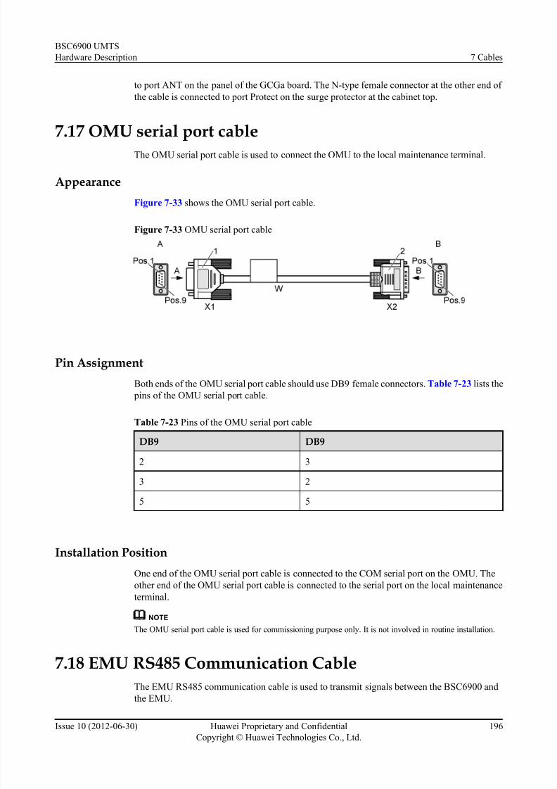
7/30/2019 BSC6900UMTS Hardware Description
http://slidepdf.com/reader/full/bsc6900umts-hardware-description 208/243
to port ANT on the panel of the GCGa board. The N-type female connector at the other end of
the cable is connected to port Protect on the surge protector at the cabinet top.
7.17 OMU serial port cableThe OMU serial port cable is used to connect the OMU to the local maintenance terminal.
Appearance
Figure 7-33 shows the OMU serial port cable.
Figure 7-33 OMU serial port cable
Pin Assignment
Both ends of the OMU serial port cable should use DB9 female connectors. Table 7-23 lists the
pins of the OMU serial port cable.
Table 7-23 Pins of the OMU serial port cable
DB9 DB9
2 3
3 2
5 5
Installation PositionOne end of the OMU serial port cable is connected to the COM serial port on the OMU. The
other end of the OMU serial port cable is connected to the serial port on the local maintenance
terminal.
NOTE
The OMU serial port cable is used for commissioning purpose only. It is not involved in routine installation.
7.18 EMU RS485 Communication Cable
The EMU RS485 communication cable is used to transmit signals between the BSC6900 andthe EMU.
BSC6900 UMTS
Hardware Description 7 Cables
Issue 10 (2012-06-30) Huawei Proprietary and Confidential
Copyright © Huawei Technologies Co., Ltd.
196
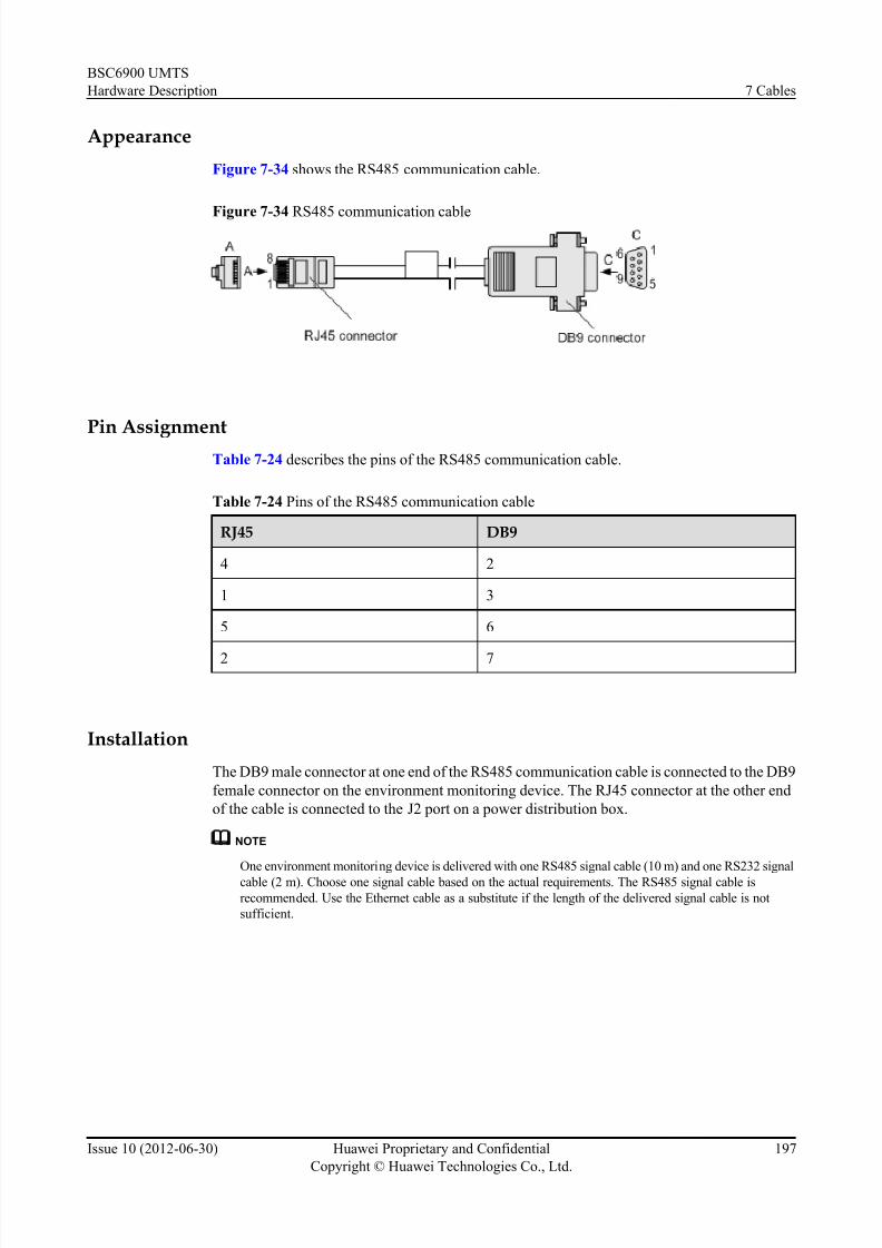
7/30/2019 BSC6900UMTS Hardware Description
http://slidepdf.com/reader/full/bsc6900umts-hardware-description 209/243
Appearance
Figure 7-34 shows the RS485 communication cable.
Figure 7-34 RS485 communication cable
Pin AssignmentTable 7-24 describes the pins of the RS485 communication cable.
Table 7-24 Pins of the RS485 communication cable
RJ45 DB9
4 2
1 3
5 6
2 7
Installation
The DB9 male connector at one end of the RS485 communication cable is connected to the DB9
female connector on the environment monitoring device. The RJ45 connector at the other end
of the cable is connected to the J2 port on a power distribution box.
NOTE
One environment monitoring device is delivered with one RS485 signal cable (10 m) and one RS232 signal
cable (2 m). Choose one signal cable based on the actual requirements. The RS485 signal cable is
recommended. Use the Ethernet cable as a substitute if the length of the delivered signal cable is not
sufficient.
BSC6900 UMTS
Hardware Description 7 Cables
Issue 10 (2012-06-30) Huawei Proprietary and Confidential
Copyright © Huawei Technologies Co., Ltd.
197

7/30/2019 BSC6900UMTS Hardware Description
http://slidepdf.com/reader/full/bsc6900umts-hardware-description 210/243
8 LEDs on the Boards
About This Chapter
This chapter describes the LEDs on the BSC6900 boards.
8.1 LEDs on the AEUa Board
There are thr ee LEDs on the AEUa board: RUN, ALM, and ACT.
8.2 LEDs on the AOUa Board
There are three LEDs on the AOUa board: RUN, ALM, and ACT.
8.3 LEDs on the AOUc Board
There are four types of LEDs on the AOUc board: RUN, ALM, ACT, and LOS.8.4 LEDs on the DPUb Board
There are three LEDs on the DPUb board: RUN, ALM, and ACT.
8.5 LEDs on the DPUe Board
There are three LEDs on the DPUe board: RUN, ALM, and ACT.
8.6 LEDs on the FG2a Board
Among all the LEDs on the FG2a board, RUN, ALM, and ACT indicate the status of the FG2a
board, and other LEDs indicate the status of Ethernet ports. There are two LEDs at each Ethernet
port: LINK and ACT.
8.7 LEDs on the FG2c Board
Among all the LEDs on the FG2c board, RUN, ALM, and ACT indicate the status of the FG2c board, and other LEDs indicate the status of Ethernet ports. There are two LEDs at each Ethernet
port: LINK and ACT.
8.8 LEDs on the GCUa/GCGa Board
There are three LEDs on the panel of the GCUa/GCGa board: RUN, ALM, and ACT.
8.9 LEDs on the GOUa Board
There are three LEDs on the GOUa board: RUN, ALM, and ACT.
8.10 LEDs on the GOUc Board
There are five types of LEDs on the GOUc board: RUN, ALM, ACT, LINK (optical port LED),
and ACT (optical port LED).
8.11 LEDs on the OMUa Board
BSC6900 UMTS
Hardware Description 8 LEDs on the Boards
Issue 10 (2012-06-30) Huawei Proprietary and Confidential
Copyright © Huawei Technologies Co., Ltd.
198

7/30/2019 BSC6900UMTS Hardware Description
http://slidepdf.com/reader/full/bsc6900umts-hardware-description 211/243
There are five types of LEDs on the OMUa board: RUN, ALM, ACT, OFFLINE, and HD.
8.12 LEDs on the PAMU Board
There are two LEDs on the PAMU board: RUN and ALM.
8.13 LEDs on the PEUa BoardThere are three LEDs on the PEUa board: RUN, ALM, and ACT.
8.14 LEDs on the POUa Board
There are three LEDs on the POUa board: RUN, ALM, and ACT.
8.15 LEDs on the POUc Board
There are four types of LEDs on the POUc board: RUN, ALM, ACT, and LOS.
8.16 LEDs on the SCUa Board
Among all the LEDs on the SCUa board, RUN, ALM, and ACT indicate the status of the SCUa
board, and other LEDs indicate the status of Ethernet ports. There are two LEDs at each Ethernet
port: LINK and ACT.
8.17 LEDs on the SPUa Board
Among all the LEDs on the SPUa board, RUN, ALM, and ACT indicate the status of the SPUb
board, and other LEDs indicate the status of Ethernet ports. There are two LEDs at each Ethernet
port: LINK and ACT.
8.18 LEDs on the SPUb Board
Among all the LEDs on the SPUb board, RUN, ALM, and ACT indicate the status of the SPUb
board, and other LEDs indicate the status of Ethernet ports. There are two LEDs at each Ethernet
port: LINK and ACT.
8.19 LEDs on the UOIa Board
There are three LEDs on the UOIa board: RUN, ALM, and ACT.
8.20 LEDs on the UOIc Board
There are four types of LEDs on the UOIc board: RUN, ALM, ACT, and LOS.
BSC6900 UMTS
Hardware Description 8 LEDs on the Boards
Issue 10 (2012-06-30) Huawei Proprietary and Confidential
Copyright © Huawei Technologies Co., Ltd.
199

7/30/2019 BSC6900UMTS Hardware Description
http://slidepdf.com/reader/full/bsc6900umts-hardware-description 212/243
8.1 LEDs on the AEUa Board
There are three LEDs on the AEUa board: RUN, ALM, and ACT.
Table 8-1 describes the LEDs on the AEUa board.
Table 8-1 LEDs on the AEUa board
LED Color Status Description
RUN Green ON for 1s and OFF for
1s
The board is functional.
ON for 0.125s and OFF
for 0.125s
The board is in loading state.
ON There is power supply, but the board
is faulty.
OFF There is no power supply, or the board
is faulty.
ALM Red OFF There is no alarm.
ON or blinking There is a fault alarm.
ACT Green ON The board is in active mode.
OFF The board is in standby mode.
8.2 LEDs on the AOUa Board
There are three LEDs on the AOUa board: RUN, ALM, and ACT.
Table 8-2 describes the LEDs on the AOUa board.
Table 8-2 LEDs on the AOUa board
LED Color Status DescriptionRUN Green ON for 1s and OFF for
1s
The board is functional.
ON for 0.125s and OFF
for 0.125s
The board is in loading state.
ON There is power supply, but the board
is faulty.
OFF There is no power supply, or the board
is faulty.
ALM Red OFF There is no alarm.
BSC6900 UMTS
Hardware Description 8 LEDs on the Boards
Issue 10 (2012-06-30) Huawei Proprietary and Confidential
Copyright © Huawei Technologies Co., Ltd.
200

7/30/2019 BSC6900UMTS Hardware Description
http://slidepdf.com/reader/full/bsc6900umts-hardware-description 213/243
LED Color Status Description
ON or blinking There is a fault alarm.
ACT Green ON The board is in active mode.
OFF The board is in standby mode.
8.3 LEDs on the AOUc Board
There are four types of LEDs on the AOUc board: RUN, ALM, ACT, and LOS.
Table 8-3 describes the LEDs on the AOUc board.
Table 8-3 LEDs on the AOUc boardLED Colo
rStatus Description
RUN Gree
n
ON for 1s and OFF for 1s The board is functional.
ON for 0.125s and OFF for
0.125s
The board is in loading state.
ON There is power supply, but the board
is faulty.
OFF There is no power supply, or the board
is faulty.
ALM Red OFF There is no alarm.
ON or blinking There is a fault alarm.
ACT Gree
n
ON The board is in active mode.
OFF The board is in standby mode.
LOS Gree
n
ON The STM-1 port does not receive
signals properly.
OFF The STM-1 port receives signals properly.
8.4 LEDs on the DPUb Board
There are three LEDs on the DPUb board: RUN, ALM, and ACT.
Table 8-4 describes the LEDs on the DPUb board.
BSC6900 UMTS
Hardware Description 8 LEDs on the Boards
Issue 10 (2012-06-30) Huawei Proprietary and Confidential
Copyright © Huawei Technologies Co., Ltd.
201

7/30/2019 BSC6900UMTS Hardware Description
http://slidepdf.com/reader/full/bsc6900umts-hardware-description 214/243
Table 8-4 LEDs on the DPUb board
LED Color Status Description
RUN Green ON for 1s and OFF for
1s
The board is functional.
ON for 0.125s and OFF
for 0.125s
The board is in loading state.
ON There is power supply, but the board
is faulty.
OFF There is no power supply, or the board
is faulty.
ALM Red OFF There is no alarm.
ON or blinking There is a fault alarm.
ACT Green ON The board is functional.
OFF The board is loading software or it is
abnormal.
8.5 LEDs on the DPUe BoardThere are three LEDs on the DPUe board: RUN, ALM, and ACT.
Table 8-5 describes the LEDs on the DPUe board.
Table 8-5 LEDs on the DPUe board
LED Color Status Description
RUN Green ON for 1s and OFF for
1s
The board is functional.
ON for 0.125s and OFF
for 0.125s
The board is in loading state.
ON There is power supply, but the board
is faulty.
OFF There is no power supply, or the board
is faulty.
ALM Red OFF There is no alarm.
ON or blinking There is a fault alarm.
ACT Green ON The board is functional.
OFF The board is loading software or it is
abnormal.
BSC6900 UMTS
Hardware Description 8 LEDs on the Boards
Issue 10 (2012-06-30) Huawei Proprietary and Confidential
Copyright © Huawei Technologies Co., Ltd.
202

7/30/2019 BSC6900UMTS Hardware Description
http://slidepdf.com/reader/full/bsc6900umts-hardware-description 215/243
8.6 LEDs on the FG2a Board
Among all the LEDs on the FG2a board, RUN, ALM, and ACT indicate the status of the FG2a
board, and other LEDs indicate the status of Ethernet ports. There are two LEDs at each Ethernet
port: LINK and ACT.
Table 8-6 describes the LEDs on the FG2a board.
Table 8-6 LEDs on the FG2a board
LED Color Status Description
RUN Green ON for 1s and OFF for 1s The board is functional.
ON for 0.125s and OFF for
0.125s
The board is in loading
state.ON There is power supply, but
the board is faulty.
OFF There is no power supply,
or the board is faulty.
ALM Red OFF There is no alarm.
ON or blinking There is a fault alarm.
ACT Green ON The board is in active
mode.
OFF The board is in standby
mode.
LINK (at the
Ethernet port)
Green ON The link is well connected.
OFF The link is disconnected.
ACT (at the
Ethernet port)
Green OFF There is no data
transmission over the
Ethernet port.
Blinking There is data transmission
over the Ethernet port.
8.7 LEDs on the FG2c Board
Among all the LEDs on the FG2c board, RUN, ALM, and ACT indicate the status of the FG2c
board, and other LEDs indicate the status of Ethernet ports. There are two LEDs at each Ethernet
port: LINK and ACT.
Table 8-7 describes the LEDs on the FG2c board.
BSC6900 UMTS
Hardware Description 8 LEDs on the Boards
Issue 10 (2012-06-30) Huawei Proprietary and Confidential
Copyright © Huawei Technologies Co., Ltd.
203

7/30/2019 BSC6900UMTS Hardware Description
http://slidepdf.com/reader/full/bsc6900umts-hardware-description 216/243
Table 8-7 LEDs on the FG2c board
LED Color Status Description
RUN Green ON for 1s and OFF for 1s The board is functional.
ON for 0.125s and OFF for
0.125s
The board is in loading
state.
ON There is power supply, but
the board is faulty.
OFF There is no power supply,
or the board is faulty.
ALM Red OFF There is no alarm.
ON or blinking There is a fault alarm.
ACT Green ON The board is in activemode.
OFF The board is in standby
mode.
LINK (at the
Ethernet port)
Green ON The link is well connected.
OFF The link is disconnected.
ACT (at the
Ethernet port)
Orange OFF There is no data
transmission over the
Ethernet port.
Blinking There is data transmission
over the Ethernet port.
8.8 LEDs on the GCUa/GCGa Board
There are three LEDs on the panel of the GCUa/GCGa board: RUN, ALM, and ACT.
Table 8-8 describes the LEDs on the GCUa/GCGa board.
Table 8-8 LEDs on the GCUa/GCGa board
LED Color Status Description
RUN Green ON for 1s and OFF for
1s
The board is functional.
ON for 0.125s and OFF
for 0.125s
The board is in loading state.
ON There is power supply, but the
board is faulty.
BSC6900 UMTS
Hardware Description 8 LEDs on the Boards
Issue 10 (2012-06-30) Huawei Proprietary and Confidential
Copyright © Huawei Technologies Co., Ltd.
204

7/30/2019 BSC6900UMTS Hardware Description
http://slidepdf.com/reader/full/bsc6900umts-hardware-description 217/243
LED Color Status Description
OFF There is no power supply, or the
board is faulty.
ALM Red OFF There is no alarm.
ON or blinking There is a fault alarm.
ACT Green ON The board is in active mode.
OFF The board is in standby mode.
8.9 LEDs on the GOUa Board
There are three LEDs on the GOUa board: RUN, ALM, and ACT.
Table 8-9 describes the LEDs on the GOUa board.
Table 8-9 LEDs on the GOUa board
LED Color Status Description
RUN Green ON for 1s and OFF for 1s The board is functional.
ON for 0.125s and OFF for
0.125s
The board is in loading
state.
ON There is power supply, butthe board is faulty.
OFF There is no power supply,
or the board is faulty.
ALM Red OFF There is no alarm.
ON or blinking There is a fault alarm.
ACT Green ON The board is in active
mode.
OFF The board is in standbymode.
8.10 LEDs on the GOUc Board
There are five types of LEDs on the GOUc board: RUN, ALM, ACT, LINK (optical port LED),
and ACT (optical port LED).
Table 8-10 describes the LEDs on the GOUc board.
BSC6900 UMTS
Hardware Description 8 LEDs on the Boards
Issue 10 (2012-06-30) Huawei Proprietary and Confidential
Copyright © Huawei Technologies Co., Ltd.
205

7/30/2019 BSC6900UMTS Hardware Description
http://slidepdf.com/reader/full/bsc6900umts-hardware-description 218/243
Table 8-10 LEDs on the GOUc board
LED Color Status Description
RUN Green ON for 1s and OFF for 1s The board is functional.
ON for 0.125s and OFF for
0.125s
The board is in loading
state.
ON There is power supply, but
the board is faulty.
OFF There is no power supply,
or the board is faulty.
ALM Red OFF There is no alarm.
ON or blinking There is a fault alarm.
ACT Green ON The board is in activemode.
OFF The board is in standby
mode.
LINK (optical
port LED)
Green ON The link is well connected.
OFF The link is disconnected.
ACT (optical
port LED)
Green OFF There is no data
transmission over the
Ethernet port.
Blinking There is data transmission
over the Ethernet port.
8.11 LEDs on the OMUa Board
There are five types of LEDs on the OMUa board: RUN, ALM, ACT, OFFLINE, and HD.
Table 8-11 describes the LEDs on the OMUa board.
Table 8-11 LEDs on the OMUa board
LED Color Status Description
RUN Green ON for 1s and OFF for 1s The board is functional.
ON for 0.125s and OFF
for 0.125s
The board is being started.
ON There is power supply, but the board
is faulty.
OFF There is no power supply, or the
board is faulty.
BSC6900 UMTS
Hardware Description 8 LEDs on the Boards
Issue 10 (2012-06-30) Huawei Proprietary and Confidential
Copyright © Huawei Technologies Co., Ltd.
206

7/30/2019 BSC6900UMTS Hardware Description
http://slidepdf.com/reader/full/bsc6900umts-hardware-description 219/243
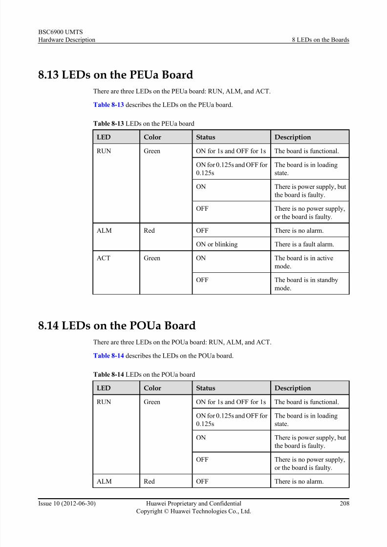
7/30/2019 BSC6900UMTS Hardware Description
http://slidepdf.com/reader/full/bsc6900umts-hardware-description 220/243
8.13 LEDs on the PEUa Board
There are three LEDs on the PEUa board: RUN, ALM, and ACT.
Table 8-13 describes the LEDs on the PEUa board.
Table 8-13 LEDs on the PEUa board
LED Color Status Description
RUN Green ON for 1s and OFF for 1s The board is functional.
ON for 0.125s and OFF for
0.125s
The board is in loading
state.
ON There is power supply, but
the board is faulty.
OFF There is no power supply,
or the board is faulty.
ALM Red OFF There is no alarm.
ON or blinking There is a fault alarm.
ACT Green ON The board is in active
mode.
OFF The board is in standby
mode.
8.14 LEDs on the POUa Board
There are three LEDs on the POUa board: RUN, ALM, and ACT.
Table 8-14 describes the LEDs on the POUa board.
Table 8-14 LEDs on the POUa board
LED Color Status Description
RUN Green ON for 1s and OFF for 1s The board is functional.
ON for 0.125s and OFF for
0.125s
The board is in loading
state.
ON There is power supply, but
the board is faulty.
OFF There is no power supply,
or the board is faulty.
ALM Red OFF There is no alarm.
BSC6900 UMTS
Hardware Description 8 LEDs on the Boards
Issue 10 (2012-06-30) Huawei Proprietary and Confidential
Copyright © Huawei Technologies Co., Ltd.
208

7/30/2019 BSC6900UMTS Hardware Description
http://slidepdf.com/reader/full/bsc6900umts-hardware-description 221/243

7/30/2019 BSC6900UMTS Hardware Description
http://slidepdf.com/reader/full/bsc6900umts-hardware-description 222/243
Table 8-16 LEDs on the SCUa board
LED Color Status Description
RUN Green ON for 1s and OFF for 1s The board is functional.
ON for 0.125s and OFF for
0.125s
The board is in loading
state.
ON There is power supply, but
the board is faulty.
OFF There is no power supply,
or the board is faulty.
ALM Red OFF There is no alarm.
ON or blinking There is a fault alarm.
ACT Green ON The board is in activemode.
OFF The board is in standby
mode.
LINK (at the
Ethernet port)
Green ON The link is well connected.
OFF The link is disconnected.
ACT (at the
Ethernet port)
Green OFF There is no data
transmission over the
Ethernet port.
Blinking There is data transmission
over the Ethernet port.
8.17 LEDs on the SPUa Board
Among all the LEDs on the SPUa board, RUN, ALM, and ACT indicate the status of the SPUb
board, and other LEDs indicate the status of Ethernet ports. There are two LEDs at each Ethernet
port: LINK and ACT.
Table 8-17 describes the LEDs on the SPUa board.
Table 8-17 LEDs on the SPUa board
LED Color Status Description
RUN Green ON for 1s and OFF for 1s The board is functional.
ON for 0.125s and OFF
for 0.125s
The board is in loading state.
ON There is power supply, but the board
is faulty.
BSC6900 UMTS
Hardware Description 8 LEDs on the Boards
Issue 10 (2012-06-30) Huawei Proprietary and Confidential
Copyright © Huawei Technologies Co., Ltd.
210

7/30/2019 BSC6900UMTS Hardware Description
http://slidepdf.com/reader/full/bsc6900umts-hardware-description 223/243
LED Color Status Description
OFF There is no power supply, or the
board is faulty.
ALM Red OFF There is no alarm.
ON or blinking There is a fault alarm.
ACT Green ON The board is in active mode.
OFF The board is in standby mode.
LINK (at the
Ethernet port)
Green ON The link is well connected.
OFF The link is disconnected.
ACT (at the
Ethernet port)
Green OFF There is no data transmission over
the Ethernet port.Blinking There is data transmission over the
Ethernet port.
8.18 LEDs on the SPUb Board
Among all the LEDs on the SPUb board, RUN, ALM, and ACT indicate the status of the SPUb
board, and other LEDs indicate the status of Ethernet ports. There are two LEDs at each Ethernet
port: LINK and ACT.
Table 8-18 describes the LEDs on the SPUb board.
Table 8-18 LEDs on the SPUb board
LED Color Status Description
RUN Green ON for 1s and OFF for 1s The board is functional.
ON for 0.125s and OFF
for 0.125s
The board is in loading state.
ON There is power supply, but the board
is faulty.
OFF There is no power supply, or the
board is faulty.
ALM Red OFF There is no alarm.
ON or blinking There is a fault alarm.
ACT Green ON The board is in active mode.
OFF The board is in standby mode.
BSC6900 UMTS
Hardware Description 8 LEDs on the Boards
Issue 10 (2012-06-30) Huawei Proprietary and Confidential
Copyright © Huawei Technologies Co., Ltd.
211

7/30/2019 BSC6900UMTS Hardware Description
http://slidepdf.com/reader/full/bsc6900umts-hardware-description 224/243

7/30/2019 BSC6900UMTS Hardware Description
http://slidepdf.com/reader/full/bsc6900umts-hardware-description 225/243
Table 8-20 LEDs on the UOIc board
LED Color
Status Description
RUN Green
ON for 1s and OFF for 1s The board is functional.
ON for 0.125s and OFF for
0.125s
The board is in loading state.
ON There is power supply, but the board
is faulty.
OFF There is no power supply, or the board
is faulty.
ALM Red OFF There is no alarm.
ON or blinking There is a fault alarm.
ACT Gree
n
ON The board is in active mode.
OFF The board is in standby mode.
LOS Gree
n
ON The STM-1 port does not receive
signals properly.
OFF The STM-1 port receives signals
properly.
BSC6900 UMTS
Hardware Description 8 LEDs on the Boards
Issue 10 (2012-06-30) Huawei Proprietary and Confidential
Copyright © Huawei Technologies Co., Ltd.
213

7/30/2019 BSC6900UMTS Hardware Description
http://slidepdf.com/reader/full/bsc6900umts-hardware-description 226/243
9 DIP Switches on Components
About This Chapter
This chapter describes the DIP switches on the boards and subracks of the BSC6900.
9.1 DIP Switch on the Subrack
The DIP switch on the subrack is used to set the number of the subrack.
9.2 DIP Switches on the AEUa Board
The AEUa board provides five DIP switches, namely, S2, S4, S6, S8, and S10.
9.3 DIP Switches on the AOUa Board
The AOUa board provides two DIP switches, both of which are labeled S1. The two DIP switchesare used to set the mode of the two STM-1/OC-3 optical ports.
9.4 DIP Switch on the PAMU Board
The PAMU provides an SW1 DIP switch.
9.5 DIP Switches on the PEUa Board
The PEUa board provides five DIP switches, namely, S2, S4, S6, S8, and S10.
9.6 DIP Switch on the PFCU Board
The PFCU board has one DIP switch, which is named SW1 and consists of four bits. The DIP
switch is used to set the address of the PFCU board. When the PFCU board is configured in a
fan box of the service subrack, the address of the PFCU board is set to 1. When the PFCU board
is configured in the independent fan subrack, the address of the PFCU board is set to 4.
9.7 Pins on the PFCB Board
The PFCB board provides eight pairs of pins for jumpers. After being connected to jumpers,
these pins are used to set the address and working mode of the PFCB board. The settings of these
pins depend on the installation position of the PFCB board.
9.8 DIP Switches on the POUa Board
The POUa board provides two DIP switches, both of which are labeled S1. The two DIP switches
are used to set the mode of the two STM-1/OC-3 optical ports.
BSC6900 UMTS
Hardware Description 9 DIP Switches on Components
Issue 10 (2012-06-30) Huawei Proprietary and Confidential
Copyright © Huawei Technologies Co., Ltd.
214

7/30/2019 BSC6900UMTS Hardware Description
http://slidepdf.com/reader/full/bsc6900umts-hardware-description 227/243
9.1 DIP Switch on the Subrack
The DIP switch on the subrack is used to set the number of the subrack.
Location of the DIP Switch
The DIP switch is located on the lower back of the subrack. For details on the location of the
DIP switch, see 5.2 Components of the Subrack .
Appearance
Figure 9-1 shows the cover plate for the DIP switch on the subrack.
Figure 9-1 Cover plate for the DIP switch on the subrack
Description about the DIP Switch
The DIP switch on the su brack has eight bits numbered in ascending order from 1 to 8. The
higher the bit is, the more significant it is. Table 9-1 describes the bits.
BSC6900 UMTS
Hardware Description 9 DIP Switches on Components
Issue 10 (2012-06-30) Huawei Proprietary and Confidential
Copyright © Huawei Technologies Co., Ltd.
215

7/30/2019 BSC6900UMTS Hardware Description
http://slidepdf.com/reader/full/bsc6900umts-hardware-description 228/243
Table 9-1 Description about the bits
Bit Description
1-5 Bits 1 to 5 are used for setting the subrack number. Bit 1 is the
least significant bit. If the bit is set to ON, it indicates 0. If the bitis set to OFF, it indicates 1.
6 Odd parity check bit
7 Reserved, undefined, generally set to ON
8 (the most significant
bit)
Startup type of the subrack, generally set to OFF.
Principle of the DIP Switch Setting As the DIP switch uses odd parity check, the number of 1s in the eight bits must be an odd
number. The method for setting the bits is as follows:
1. Set bit 1 to bit 5 as required.
2. Set bit 7 to ON.
3. Set bit 8 to OFF.
4. Check the number of 1s in the seven bits of the DIP switch. Note that the setting of bit 8
remains unchanged.
l If the number of 1s is even, set bit 6 to OFF.
l If the number of 1s is odd, set bit 6 to ON.
Assume that the subracks are numbered from 0 to 5 and that bit 8 is set to OFF. Table 9-2
describes the setting of the DIP switch in the case.
Table 9-2 Setting of the DIP switch
SubrackNo.
Bit Setting of the DIPSwitch
1 2 3 4 5 6 7 8
0 0 0 0 0 0 0 0 1
ON ON ON ON ON ON ON OFF
1 1 0 0 0 0 1 0 1
OFF ON ON ON ON OFF ON OFF
2 0 1 0 0 0 1 0 1
ON OFF ON ON ON OFF ON OFF
3 1 1 0 0 0 0 0 1
OFF OFF ON ON ON ON ON OFF
BSC6900 UMTS
Hardware Description 9 DIP Switches on Components
Issue 10 (2012-06-30) Huawei Proprietary and Confidential
Copyright © Huawei Technologies Co., Ltd.
216

7/30/2019 BSC6900UMTS Hardware Description
http://slidepdf.com/reader/full/bsc6900umts-hardware-description 229/243
SubrackNo.
Bit Setting of the DIPSwitch
1 2 3 4 5 6 7 8
4 0 0 1 0 0 1 0 1
ON ON OFF ON ON OFF ON OFF
5 1 0 1 0 0 0 0 1
OFF ON OFF ON ON ON ON OFF
9.2 DIP Switches on the AEUa Board
The AEUa board provides five DIP switches, namely, S2, S4, S6, S8, and S10.
Layout of the DIP Switches
Figure 9-2 shows the layout of the DIP switches on the AEUa board.
BSC6900 UMTS
Hardware Description 9 DIP Switches on Components
Issue 10 (2012-06-30) Huawei Proprietary and Confidential
Copyright © Huawei Technologies Co., Ltd.
217

7/30/2019 BSC6900UMTS Hardware Description
http://slidepdf.com/reader/full/bsc6900umts-hardware-description 230/243
Figure 9-2 Layout of the DIP switches on the AEUa board
(1) Sub-board (2) Bottom plate
BSC6900 UMTS
Hardware Description 9 DIP Switches on Components
Issue 10 (2012-06-30) Huawei Proprietary and Confidential
Copyright © Huawei Technologies Co., Ltd.
218

7/30/2019 BSC6900UMTS Hardware Description
http://slidepdf.com/reader/full/bsc6900umts-hardware-description 231/243
NOTE
l All DIP switches are on the front panel of the sub-board. The front panel is combined with the bottom
plate, so the DIP switches are not exposed.
l DIP switches S2, S4, S6, S8, and S10 are set from the side. As shown in Figure 9-2, there are two
square holes between DIP switches, one between S2 and S4, and the other between S8 and S6. Throughthe two holes, you can set S2, S4, S8, and S6. DIP switch S10 is located in the right corner of the sub-
board, and thus you can set S10 along the side. The direction of the arrow in Figure 9-2 is to turn
inwards. To set the bits of S2, S4, S6, or S8 to ON, turn them inwards. To set the bits of S2, S4, S6, or
S8 to OFF, turn them outwards. To set the bits of S10 to ON, turn them outwards. To set the bits of
S10 to OFF, turn them inwards.
l You can also run the SET E1T1 command on the LMT to set S10. If there is any inconsistency between
the physical setting of S10 on the AEUa board and the setting of S10 by command, take the setting by
command as the criterion. By default, the working mode of S10 is set to E1. You can also run the SET
E1T1 command on the LMT to change the working mode of S10 from E1 mode to E1 balanced mode,
E1 unbalanced mode, or T1 mode. When you run the SET E1T1 command to set the support for
balanced and unbalanced modes parameter to No and set the working mode of S10 to E1, you must
also manually set the bits of S10 to set the working mode of S10 to E1 balanced mode or E1 unbalanced
mode.l If signals are transmitted in E1 unbalanced mode, the signals are transmitted through the 75-ohm coaxial
cable and the TX end of the cable is grounded, that is, the corresponding DIP bit is set to ON. If signals
are transmitted in E1(T1) balanced mode, the signals are transmitted through the 120-ohm twisted pair
cable and the TX end of the cable is not grounded, that is, the corresponding DIP bit is set to OFF.
Description of the DIP Switches
DIP switches S2, S4, S6, and S8 on the AEUa board are used to enable or disable the grounding
of 0 to 31 E1s/T1/J1s at the TX end. DIP switch S10 is used to set the working mode to E1
balanced mode, E1 unbalanced mode, T1 mode, or J1 mode. Table 9-3 describes S2, S4, S6,
S8, and S10.
Table 9-3 Description of the DIP switches on the AEUa board
DIP Switch Bit Description Setting ofDIP Bit
Meaning
S2 1-8 TX ground switch
of E1s/T1s/J1s 24
to 31
ON Setting the working
mode to E1 unbalanced
mode
OFF Setting the working
mode to other modes
S4 1-8 TX ground switch
of E1s/T1s/J1s 16
to 23
ON Setting the working
mode to E1 unbalanced
mode
OFF Setting the working
mode to other modes
S6 1-8 TX ground switch
of E1s/T1s/J1s 0
to 7
ON Setting the working
mode to E1 unbalanced
mode
OFF Setting the working
mode to other modes
BSC6900 UMTS
Hardware Description 9 DIP Switches on Components
Issue 10 (2012-06-30) Huawei Proprietary and Confidential
Copyright © Huawei Technologies Co., Ltd.
219

7/30/2019 BSC6900UMTS Hardware Description
http://slidepdf.com/reader/full/bsc6900umts-hardware-description 232/243
DIP Switch Bit Description Setting ofDIP Bit
Meaning
S8 1-8 TX ground switch
of E1s/T1s/J1s 8
to 15
ON Setting the working
mode to E1 unbalanced
mode
OFF Setting the working
mode to other modes
S10 1-2 DIP switch for
setting the
working mode,
consisting of two
bits
(ON, ON) Setting the working
mode to E1 unbalanced
mode
(OFF, ON) Setting the working
mode to E1 balanced
mode
(ON, OFF) Setting the working
mode to T1 mode
(OFF, OFF) Setting the working
mode to J1 mode
NOTE
All the DIP switches are set to E1 balanced mode by default, that is, all the bits of S2, S4, S6, and S8 are
set to OFF. For S10, the first bit is set to OFF, and the second bit to ON.
9.3 DIP Switches on the AOUa Board
The AOUa board provides two DIP switches, both of which are labeled S1. The two DIP switches
are used to set the mode of the two STM-1/OC-3 optical ports.
Layout of the DIP Switches
Figure 9-3 shows the layout of the DIP switches on the AOUa board.
BSC6900 UMTS
Hardware Description 9 DIP Switches on Components
Issue 10 (2012-06-30) Huawei Proprietary and Confidential
Copyright © Huawei Technologies Co., Ltd.
220

7/30/2019 BSC6900UMTS Hardware Description
http://slidepdf.com/reader/full/bsc6900umts-hardware-description 233/243
Figure 9-3 Layout of the DIP switches on the AOUa board
(1) Sub-board (2) Bottom plate
CAUTION
All DIP switches of the AOUa board are on the front panel of the sub-board. The front panel is
faced to and combined with the bottom plate, and so the DIP switches are hidden in between.
Description of the DIP SwitchesTable 9-4 describes the DIP switches on the AOUa board.
Table 9-4 Description of the DIP switches on the AOUa board
DIP Switch Bit Setting ofDIP Bit
Meaning
S1 1-2 (ON, ON) Setting loading mode to JTAG
configuration
(OFF, OFF) Setting loading mode to CPU slave parallel
configuration
BSC6900 UMTS
Hardware Description 9 DIP Switches on Components
Issue 10 (2012-06-30) Huawei Proprietary and Confidential
Copyright © Huawei Technologies Co., Ltd.
221

7/30/2019 BSC6900UMTS Hardware Description
http://slidepdf.com/reader/full/bsc6900umts-hardware-description 234/243
DIP Switch Bit Setting ofDIP Bit
Meaning
3 ON Setting working mode to T1 mode
OFF Setting working mode to E1 mode
4 ON Setting the mapped path to AU3
OFF Setting the mapped path to AU4
5 ON Setting the information structure to TU11
OFF Setting the information structure to TU12
6 ON SONET
OFF SDH
7 - Reserved
8 - Reserved
NOTE
All the bits of the two DIP switches are set to OFF by default.
9.4 DIP Switch on the PAMU Board
The PAMU provides an SW1 DIP switch.
Figure 9-4 shows the layout of the DIP switch on the PAMU board.
Figure 9-4 Layout of the DIP switch on the PAMU board
With four bits, the DIP switch SW1 is used to set the address of the PAMU board.
To set the address, first remove the PAMU board and then set the SW1 as described in Table
9-5.
BSC6900 UMTS
Hardware Description 9 DIP Switches on Components
Issue 10 (2012-06-30) Huawei Proprietary and Confidential
Copyright © Huawei Technologies Co., Ltd.
222

7/30/2019 BSC6900UMTS Hardware Description
http://slidepdf.com/reader/full/bsc6900umts-hardware-description 235/243
Table 9-5 DIP switch on the PAMU board
Address Bit Setting of DIP Bit Description
0 1 (the most significant
bit)
ON 0
2 ON 0
3 ON 0
4 (the least significant
bit)
ON 0
NOTE
In the BSC6900, the DIP switch on the PAMU board must be set as described in Table 9-5.
9.5 DIP Switches on the PEUa Board
The PEUa board provides five DIP switches, namely, S2, S4, S6, S8, and S10.
Figure 9-5 shows the layout of the DIP switches on the PEUa board.
BSC6900 UMTS
Hardware Description 9 DIP Switches on Components
Issue 10 (2012-06-30) Huawei Proprietary and Confidential
Copyright © Huawei Technologies Co., Ltd.
223

7/30/2019 BSC6900UMTS Hardware Description
http://slidepdf.com/reader/full/bsc6900umts-hardware-description 236/243
Figure 9-5 Layout of the DIP switches on the PEUa board
(1) Sub-board (2) Bottom plate
BSC6900 UMTS
Hardware Description 9 DIP Switches on Components
Issue 10 (2012-06-30) Huawei Proprietary and Confidential
Copyright © Huawei Technologies Co., Ltd.
224

7/30/2019 BSC6900UMTS Hardware Description
http://slidepdf.com/reader/full/bsc6900umts-hardware-description 237/243
NOTE
l All DIP switches are on the front panel of the sub-board. The front panel is combined with the bottom
plate, so the DIP switches are not exposed.
l DIP switches S2, S4, S6, S8, and S10 are set from the side. As shown in Figure 9-5, there are two
square holes between DIP switches, one between S2 and S4, and the other between S8 and S6. Throughthe two holes, you can set S2, S4, S8, and S6. DIP switch S10 is located in the right corner of the sub-
board, and thus you can set S10 along the side. The direction of the arrow in Figure 9-5 is to turn
inwards. To set the bits of S2, S4, S6, or S8 to ON, turn them inwards. To set the bits of S2, S4, S6, or
S8 to OFF, turn them outwards. To set the bits of S10 to ON, turn them outwards. To set the bits of
S10 to OFF, turn them inwards.
l You can also run the SET E1T1 command on the LMT to set S10. If there is any inconsistency between
the physical setting of S10 on the PEUa board and the setting of S10 by command, take the setting by
command as the criterion. By default, the working mode of S10 is set to E1. You can also run the SET
E1T1 command on the LMT to change the working mode of S10 from E1 mode to E1 balanced mode,
E1 unbalanced mode, or T1 mode. When you run the SET E1T1 command to set the support for
balanced and unbalanced modes parameter to No and set the working mode of S10 to E1, you must
also manually set the bits of S10 to set the working mode of S10 to E1 balanced mode or E1 unbalanced
mode.
l If signals are transmitted in E1 unbalanced mode, the signals are transmitted through the 75-ohm coaxial
cable and the TX end of the cable is grounded, that is, the corresponding DIP bit is set to ON. If signals
are transmitted in E1(T1) balanced mode, the signals are transmitted through the 120-ohm twisted pair
cable and the TX end of the cable is not grounded, that is, the corresponding DIP bit is set to OFF.
DIP switches S2, S4, S6, and S8 on the PEUa board are used to enable or disable the grounding
of 0 to 31 E1s/T1s/J1s at the TX end. DIP switch S10 is used to set the working mode to E1
balanced mode, E1 unbalanced mode, T1 mode, or J1 mode. Table 9-6 describes the DIP
switches on the PEUa board.
Table 9-6 Description about DIP switches on the PEUa board
DIPSwitch
Bit Description Setting of DIPSwitch
Meaning
S2 1-8 TX ground switch of
E1s/T1s/J1s 24 to 31
ON Setting the
working mode to
E1 unbalanced
mode
OFF Setting the
working mode to
other modes
S4 1-8 TX ground switch of
E1s/T1s/J1s 16 to 23
ON Setting the
working mode to
E1 unbalanced
mode
OFF Setting the
working mode to
other modes
S6 1-8 TX ground switch of
E1s/T1s/J1s 0 to 7
ON Setting the
working mode to
E1 unbalanced
mode
BSC6900 UMTS
Hardware Description 9 DIP Switches on Components
Issue 10 (2012-06-30) Huawei Proprietary and Confidential
Copyright © Huawei Technologies Co., Ltd.
225

7/30/2019 BSC6900UMTS Hardware Description
http://slidepdf.com/reader/full/bsc6900umts-hardware-description 238/243
DIPSwitch
Bit Description Setting of DIPSwitch
Meaning
OFF Setting the
working mode to
other modes
S8 1-8 TX ground switch of
E1s/T1s/J1s 8 to 15
ON Setting the
working mode to
E1 unbalanced
mode
OFF Setting the
working mode to
other modes
S10 1-2 DIP switch for setting theworking mode,
consisting of two bits
(ON, ON) Setting theworking mode to
E1 unbalanced
mode
(OFF, ON) Setting the
working mode to
E1 balanced
mode
(ON, OFF) Setting the
working mode to
T1 mode
(OFF, OFF) Setting the
working mode to
J1 mode
NOTE
All the DIP switches are set to E1 balanced mode by default, that is, all the bits of S2, S4, S6, and S8 are
set to OFF. For S10, the first bit is set to OFF, and the second bit to ON.
9.6 DIP Switch on the PFCU Board
The PFCU board has one DIP switch, which is named SW1 and consists of four bits. The DIP
switch is used to set the address of the PFCU board. When the PFCU board is configured in a
fan box of the service subrack, the address of the PFCU board is set to 1. When the PFCU board
is configured in the independent fan subrack, the address of the PFCU board is set to 4.
DIP Switch on the PFCU Board (in a Fan Box of the service subrack)
Figure 9-6 shows the DIP switch on the PFCU board.
BSC6900 UMTS
Hardware Description 9 DIP Switches on Components
Issue 10 (2012-06-30) Huawei Proprietary and Confidential
Copyright © Huawei Technologies Co., Ltd.
226

7/30/2019 BSC6900UMTS Hardware Description
http://slidepdf.com/reader/full/bsc6900umts-hardware-description 239/243
Figure 9-6 DIP switch on the PFCU board
To set the address of the PFCU board, remove the fan box, and then set SW1 as described in
Table 9-7. For how to remove the fan box, see Replacing the Fan Box. After the setting, the
address of the PFCU board is 1.
Table 9-7 DIP switch on the PFCU board (in a fan box of the service subrack)
DIP Switch Bit Setting of DIPSwitch Description
SW1 1 (the least significant
bit)
OFF 1
2 ON 0
3 ON 0
4 (the most significant
bit)
ON 0
DIP Switch on the PFCU Board (in the Independent Fan Subrack)
Figure 9-7 shows the DIP switch on the PFCU board.
Figure 9-7 DIP switch on the PFCU board
To set the address of the PFCU board, remove the fan box, and then set SW1 as described in
Table 9-8. For how to remove the fan box, see Replacing the Fan Box. After the setting, the
address of the PFCU board is 4.
BSC6900 UMTS
Hardware Description 9 DIP Switches on Components
Issue 10 (2012-06-30) Huawei Proprietary and Confidential
Copyright © Huawei Technologies Co., Ltd.
227

7/30/2019 BSC6900UMTS Hardware Description
http://slidepdf.com/reader/full/bsc6900umts-hardware-description 240/243
Table 9-8 DIP switch on the PFCU board (in the independent fan subrack)
DIP Switch Bit Setting of DIPSwitch
Description
SW1 1 (the least significant bit)
ON 0
2 ON 0
3 OFF 1
4 (the most significant
bit)
ON 0
NOTE
The DIP switch on the PFCU board of the BSC6900 must be set according to the preceding descriptions.
9.7 Pins on the PFCB Board
The PFCB board provides eight pairs of pins for jumpers. After being connected to jumpers,
these pins are used to set the address and working mode of the PFCB board. The settings of these
pins depend on the installation position of the PFCB board.
Pins on the PFCB Board (in a Fan Box of the service subrack)
Figure 9-8 shows the pins on the PFCB board.
Figure 9-8 Pins on the PFCB board
To set the address of the PFCB board, first remove the fan box and then set the pins as describedin Table 9-9.
Table 9-9 Pins on the PFCB board (in a fan box of the service subrack)
PinNumber
1-2 3-4 5-6 7-8 9-10 11-12 13-14 15-16
Connec
ted to
jumper
No No No No Yes No No No
BSC6900 UMTS
Hardware Description 9 DIP Switches on Components
Issue 10 (2012-06-30) Huawei Proprietary and Confidential
Copyright © Huawei Technologies Co., Ltd.
228

7/30/2019 BSC6900UMTS Hardware Description
http://slidepdf.com/reader/full/bsc6900umts-hardware-description 241/243

7/30/2019 BSC6900UMTS Hardware Description
http://slidepdf.com/reader/full/bsc6900umts-hardware-description 242/243
Figure 9-10 Layout of the DIP switches on the POUa board
(1) Sub-board (2) Bottom plate
CAUTION
All the DIP switches on the POUa board are on the front panel of the sub-board. The front panel
is faced to and combined with the bottom plate, and so the DIP switches are hidden in between.
Description of the DIP SwitchesTable 9-11 describes the DIP switches on the POUa board.
Table 9-11 Description of the DIP switches on the POUa board
DIP Switch Bit Setting of DIP Bit Meaning
S1 1-2 (ON, ON) Setting loading mode
to JTAG configuration
(OFF, OFF) Setting loading mode
to CPU slave parallel
configuration
BSC6900 UMTS
Hardware Description 9 DIP Switches on Components
Issue 10 (2012-06-30) Huawei Proprietary and Confidential
Copyright © Huawei Technologies Co., Ltd.
230
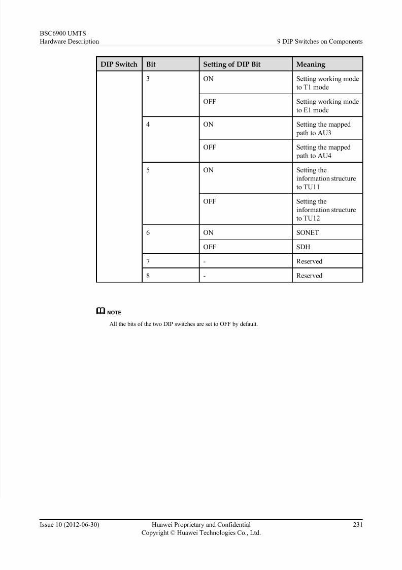
7/30/2019 BSC6900UMTS Hardware Description
http://slidepdf.com/reader/full/bsc6900umts-hardware-description 243/243
DIP Switch Bit Setting of DIP Bit Meaning
3 ON Setting working mode
to T1 mode
OFF Setting working modeto E1 mode
4 ON Setting the mapped
path to AU3
BSC6900 UMTS
Hardware Description 9 DIP Switches on Components