Embed Size (px)
Citation preview

BS 812 : Part 3 : 1975UDC {625.7.07 :620.1} : 620.17 : 531
(Reprinted, incorporating Amendments No. 1to No. 5 inclusive)
Testing aggregates
Part 3. Methods for determination ofmechanical properties
British Standards Institution

This British Standard. having been approved by the Road Engineermg Industry Standards Committee, was published under theauthorit! ot the Lxccutnc Board on 31 July 1975.
GBritish Standards Institution, 1975
BS 812 first published October 1938 and revised in 1943, 1951. 1960 and 1967BS 812 : Part 3 first published July 1975
ISBN 0 580 08764 6
British Standards Institution
incorporated bq Royal Charter. BSI is the tndependent natlonal body for the preparation of British Standards. 11 is the UKmember of the lntematlonai Organlzatlon for Standardlzation and UK sponsor of the British NatIonal Committee of thelntcrnatlonal Electrotechnlcal Commission.
Copyright
L;\cr\ of Brltlsh Standards arc remlnded that copyrlght subsists In all BSI pubhcations. NO part of this publlcatlon ma! bereproduced In an> form wIthout the prior permIssIon m writing of BSI. This does not preclude the free use. m the course oflmplcmentlng the standard. of necessary details such as symbols and size. type or grade designations. Enquiries by post should beaddressed to the Publlcatlons Manager. Brltlsh Standards Instltutron. Lmford Wood. Milton Keynes MK14 6LE. The number fortclephonc enqulrle\ 1\ 0908 220021 and for telex 825777.
Contract requirements
A British Standard does not purport to include all the necessary provisions ofa contract. Users ofBritish Standards are responsibiefor their correct application.
L Revision of British Standards
British Standards are revised. when necessary, by the issue either of amendments or of revised editions. It is important that users ofBritish Standards should ascertain that they are in possession of the latest amendments or editions. Information on all BSIpublications is in the BSI C’urulo~ur, supplemented each month by BSI Nervs which is available to subscribing members of thelnstltutlon and gives details of new publications. revisions, amendments and withdrawn standards. Any person who, when makinguse of a Br1tls.h Standard. encounters an Inaccuracy or ambiguity. is requested to notify BSI without delay in order that the matterma! be mvestlgatcd and appropriate action taken.
The following BSI references relate to the work on this standard:Committee reference RDEi5 Draft for comment 72/43780 DC
Co-operating organizationsThe Road IinFinccrinp Standards Committee, under whose supervision this British Standard was prepared, consists ofrcprescntatlvcr from the following Government departments and scientific and industrial organizations:
'Asphalt and Cuatcd Macadam AssociationAssociation of Consulting Lnpinecrs
*British Quarrymg and Slap Federation*British Tar Industry Association“Ccmcnt and Concrctc Asrociation‘(‘oncrctc Soclcty (Dcslgn and Development Divisional
Committee)(‘onlractors’ Plant Association
*County Surveyors’ Socict!*Department of the tnvironmcnt*Department of the Environment, Transport and Road
Rcscarch LaboratoryI:cdcration of Civil Cngincermg ContractorsI:cderation of Manufacturers of Construction Equipment
and Cranes
*Greater London CouncilInstitute of PetroleumInstitute of Quarrying
*Institution of Civil Engineers*Institution of Highway Engineers*Institution of Municipal Engineers
Institution of Structural EngineersMinistry of DefenceRefined Bitumen Association LimitedRoad Emulsion Association LimitedRoad Surface Dressing Association
*Sand and Gravel Association LimitedSociety of Chemical industry
The orgamzations marked with an asterisk in the above list, together with the following, were directly represented on thecommittee cntrustcd with the preparation of the British Standard:
Association of London Borough Engineers and SurveyorsDepartment of the Environment (Building Research
Estahlishmcnt)
Natural Environment Research Council-Institute ofGeological Science
8 9 0 7 - 7 - O 5k-B .

BS 812 : Part 3 :‘I975UDC r625.7.07 : 620.1 I : 620.17 : 531
Testing aggregates
Part 3. Methods for determination ofmechanical properties
Amendments issued since publication
Amd. No.
2153
4225
4455
4616
4845
Date of issue Text affected
November 1976 Indicated by a line in the margin
March 1983 Indicated by a line in the margin
December 1983 Indicated by a line in the margin
August 1984 Indicated by a line in the margin
February 1985 Indicated by a line in the margin
British Standards Institution - 2 Park Street - London WlA 2BSTelephone 01-629 4000
Telex 266933

BS812:Part3:1975
ContentsCo-operating organizationsForeword
M e t h o d s
1. Scope2. References3. Reporting4. Significance of the results5. General
PageInside front cover
6. Determination of aggregate impact value 37. Determination of aggregate crushing value 58. Determination of the ten per cent
fines value 89. Determination of aggregate abrasion value 9
10. Determination of the polished-stone value 101. Alternative method for determination of
the polished-stone value
Appendix
A. Repeatability and reproducibility of testresults
Page
Tables
1. Particulars of BS test sieves for testingstandard and non-standard sizes ofaggregate as described in clauses 6,7 and 8
2. Properties of slider3. Calculation of PSV
1 3a. Calculation of PSV (alternative method)4. Estimates of the repeatability and
reproducibility of a number of tests foraggregates
Figures
51416
18
1. Aggregate impact test machine 42. Outline form and principal dimensions of
cylinder and plunger apparatus for aggregatecrushing test 6

BS812:Part3:1975
ForewordThis British Standard has been prepared, under theauthority of the Road Engineering IndustryStandards Committee, using metric dimensions aspart of the national policy to change to the metricsystem. BS 8 12 was first published in 1938 andsubsequently revised in 1943, 1951,196O and 1967.
Guidance on sampling and testing aggregates,including procedures for assessing the precision ofmethods of test, is given in BS 8 12 : Part 101. OtherParts of BS 8 12 published are as follows.
Part 102 Methods for samplingPart 1 Methods for determination of particle
size and shapePart 2 Methods for determination of physical
propertiesPart 4 Methods for determination of chemical
properties.
In this Part of the standard changes have beenintroduced to simplify the determination of theaggregate abrasion value and to improve theprecision of the determination of the polished-stonevalue by comparing the test value with thepolished-stone value of a stone of known stability.The change to rational metric dimensions hasaffected most of the apparatus detailed in this Partof the standard and the metric sizes of aggregatesnow regarded as standard may not give the sameresults as those obtained by earlier methods.
The test for the determination of crushingstrength of cylinders cut from rock, included inearlier editions of this standard, has been omittedfrom this revision because experience has shownthe repeatability and reproducibility of the resultsto be very poor and also because a more reliableassessment of the performance of aggregates can beobtained from tne other tests for mechamcal
properties.Information on any other methods of test that are
thought suitable for extensive use, or suggestionsfor improvement of the specified methods, arewelcomed and will be considered when it becomesdesirable again to revise the standard.
In particular views would be welcomed on theneed to retain both the aggregate crushing value andthe ten per cent fines value tests. The latter wasintroduced in 1960 to provide a method which isapplicable to all aggregates because the aggregatecrushing value may yield anomalous results forsofter materials, having values of 30 or higher.
Attention is drawn to the companion standardBS 3681 ‘Methods for the sampling and testing oflightweight aggregates for concrete’.
The Enderby control stone and the pneumatic tyreused in the method given in clause 10 for determina-tion of the polished stone value are no longer inproduction. An alternative modified method istherefore given in clause 11 which uses a new controlstone and a solid rubber tyre both of which arereadily available. In order to improve consistency!supplies of the new control stone are to be obtainedfrom a stockpile held by the Transport and RoadResearch Laboratory, Old Wokingham Road.Crowthorne, Berks RGll 6AU. Either of themethods given in clauses 10 and 11 may be used andcan be expected to give comparable results.The alternative method is basically the same as thatgiven in clause 10 except that some differences havebeen introduced to accommodate the new controlstone and the solid rubber tyre. Clause 10 will bewithdrawn as soon as there is evidence that thestocks held by some test laboratories of the Enderbycontrol stone and pneumatic tyre used in that clausehave been exhausted. While the addition of thealternative modified method has become urgentbecause the Enderby control stone and pneumatictyre used in clause 10 are in short supply. a fullerrevision is planned and comments relating to animproved test are invited.
3

BS812:Part3:1975
British Standard
Testing aggregates
Part 3. Methods for determination of mechanical properties
1. Scope
This Part of the standard specifies methods for thedetermination of the aggregate impact value,aggrerate crushing value, ten per cent fines value,‘.*oreiate abrasion value and polished-stone valueGgg:egates.
The tests are intended for use in obtainingassurance that material complies with specifiedrequirements. for research, production control orassessment of variation and are done on certainsize fractions
2. References
The titles of the British Standards referred to in thisstandard are listed on the inside back cover.
3. Reporting
3.1 General. The report shall affirm that the tests\+ere done in accordance with this standard. Anydeparture from the specified test procedure shall bedescribed with reasons for the departure and, ifpossible. estimates of its effect on the test results.The report shall also include details of any specialprocessing of the sample, other than that required‘c he test methods. carried out in the laboratory.h.example. crushing to provide larger quantitiesol~smaller sizes or the separation of constituentsfrom an as-dug gravel.
3.2 Certificate of sampling. The report shall affirmthat a certificate of sampling was received with thesample and shall declare all the information givenon the certificate. If a certificate was not receivedthis shall be stated in the report.
4. Significanceof the results
The distribution of the results of any test on anymaterial stems from a number ofcontributingfactors. In assessing the significance of the results!:IC rcpearabilir!, and reproducibillr>, of the test shouldbe recognized. Estimates of these are given inappendix A and should be used in assessing testresults.
5. General
,411 the tests in this Part of the standard are carriedout on certain size fractions x\hich normally have tobe sic\ ed out from the laboratory sample. Wheresuch a fraction constitutes less than 15 “A of the
4
total sample the results may not be representative.The aggregate impact test, aggregate crushing testand the ten per cent fines test are likely to beaffected to a greater extent than the aggregateabrasion test and polished-stone test where flakyparticles are separated in preparing the test sample.Under such circumstances the followingrecommendations should provide a morerepresentative test sample:
(a) where general assurance about a given sourceof aggregate is required a further sample of adifferent grade and containing more than 15 % ofthe required size should be obtained and tested;(b) where a particular consignment is to betested for impact value, crushing value or ten percent fines value, a non-standard size should betested.In the event of neither of these options proving
possible it may be necessary to test the originalfraction. The report shall state the fact when afurther sample was obtained, when a non-standardsize was tested or when the test was made on afraction containing less than 15 % of the laboratorysample.
6. Determination of aggregate impactvalue
6.1 General. The aggregate impact value gives arelative measure of the resistance of an aggregate tosudden shock or impact, which in some aggregatesdiffers from its resistance to a slowly appliedcompressive load. With aggregate of aggregateimpact value higher than 30 the result may beanomalous. Also, aggregate sizes larger than 14 mmare not appropriate to the aggregate impact test.
The standard aggregate impact test shall be madeon aggregate passing a 14.0 mm BS test sieve andretained on a 10.0 mm BS test sieve. If required, orif the standard size is not available, smaller sizesmay be tested but owing to the non-homogeneity ofaggregates the results are not likely to be the sameas those obtained from the standard size. In general,the smaller sizes of aggregate will give a lowerimpact value but the relationship between the valuesobtained with different sizes may vary from oneaggregate to another.
6.2 Sampling. The sample for this test shall betaken in accordance with Part 103 of this standard.standard.
J

BS812:Part3:1'975
L”
*/
6.3 Apparatus. The following apparatus is required.6.3.1 An impact testing machine of the general formshown in figure 1 and complying with the following.
(a) Total mass not more than 60 kg nor less than45 kg.
Lockinq pin for
reIea* mechrnism\ Adjustab le s top
Ratchet counter.(to count number“. *I-.“-\
L i f t ing handler
\
/j 1 1 j!
Cyl indr ica l s tee l cup,
Inner surfaces
Dimensions are in millimetres
NOTE. As a temporary measure, apparatus complying withthe requirements of BS 812 : 1967 (now withdrawn) shall bedeemed to comply with this requirement.
Figure 1. Aggregate impact test machine
The machine shall have a circular metal baseweighing between 22 kg and 30 kg, with a planelower surface of nqt less than 300 mm diameter,and shall be supported on a level and planeconcrete or stone block or floor at least 450 mmthick. The machine shall be prevented fromrocking either by fixing it to the block or floor orby supporting it on a level and plane metal platecast into the surface of the block or floor.(b) A cylindrical steel cup having an internaldiameter of 102 mm and an internal depth of50 mm. The walls shall be not less than 6 mmthick and the inner surfaces shall be casehardened. The cup shall be rigidly fastened at thecentre of the base and be easily removed foremptying.(c) A metal hammer weighing 13.5 kg to 14.0 kgthe lower end of which shall be cylindrical inshape, 100.0 mm diameter and 50 mm long, witha 1.5 mm chamfer at the lower edge, and casehardened. The hammer shall slide freely between
vertical guides so arranged that the lower(cylindrical) part of the hammer is above andconcentric with the cup.(d) Means for raising the hammer and allowing itto fall freely between the vertical guides from aheight of 380 f 5 mm on to the test sample inthe cup, and means for adjusting the height offall within 5 mm.(e) Means for supporting the hammer whilstfastening or removing the cup.
NOTE. Some means for automatically recording the numberof blows is desirable.
6.3.2 BS test sieves of aperture sizes 14.0 mm,10.0 mm and 2.36 mm, for a standard test. For testson aggregate sizes smaller than the standard, theappropriate aperture sizes of sieves shown intable 1 shall be used (see 7.1.3.1 of Part 1 of thisstandard).6.3.3 A cylindrical metal measure of sufficientrigidity to retain its form under rough usage andwith an internal diameter of 75 + 1 mm and aninternal depth of 50 & 1 mm.6.3.4 A straight metal tamping rod of circular crosssection. 10 mm diameter, 230 mm long, roundedat one end.6.3.5 A balance of capacity not less than 500 g, andaccurate to 0.1 g.6.4 Preparation of the test sample. The materialfor the standard test shall consist of aggregatepassing a 14.0 mm BS test sieve and retained on a10.0 mm BS test sieve and shall be thoroughlyseparated on these sieves before testing. For smallersizes the aggregate shall be prepared in a similarmanner using the appropriate sieves given in table 1.The quantity of aggregate sieved out shall besufficient for two tests.
The aggregate shall be tested in a surface-drycondition. If dried by heating, the period of dryingshall not exceed 4 h, the temperature shall notexceed 110 “C and the samples shall be cooled toroom temperature before testing.
The measure shall be filled about one third fullwith the aggregate by means of a scoop, theaggregate being discharged from a height notexceeding 50 mm above the top of the container.The aggregate shall then be tamped with 25 blowsof the rounded end of the tamping rod, each blowbeing given by allowing the tamping rod to fallfreely from a height of about 50 mm above thesurface of the aggregate and the blows being evenlydistributed over the surface. A further similarquantity of aggregate shall be added in the samemanner and a further tamping of 25 blows given.The measure shall finally be filled to overflowing,tamped 25 times and the surplus aggregate removedby roiling the tamping rod across, and in contactwith, the top of the container, any aggregate whichimpedes its progress being removed by hand andaggregate being added to fll any obviousdepressions. The net mass of aggregate in themeasure shall be recorded (mass A) and the samemass used for the second test.

BS812:Pat-t3:1975
6.5 Test procedure. Rest the impact machine, Table 1. Particulars of BS test sieves forwithout wedging or packing, upon the level plate, testing standard and non-standard sizesblock or floor, so that it is rigid and the hammer of aggregate as described in clauses 6,7guide columns are vertical. and 8
Fix the cup firmly in position on the base of themachine and place the whole of the test sample in itand compact by a single tamping of 25 strokes ofthe tamping rod as above.
Nomid aperture sizes of BS test sievescomplying with the requirements ofBS 410 (full tolerance)
Adjust the height of the hammer so that its lowerface is 380 + 5 mm above the upper surface of theaggregate in the cup and then allow it to fall freelyon to the aggregate. Subject the test sample to atotal of 15 such blows, each being delivered at aninterval of not less than 1 s. No adjustment forhammer height is required after the first blow.
Sample size for sample preparation for separatbgpassing r e t a i n e d tines
Non-standard :?I20.0
~~m m urn5.00 -
14.0 3.35 -
Then remove the crushed aggregate by holdingthe cup over a clean tray and hammering on theoutside with a suitable rubber mallet until the
Standard 14.0 10.0 2.36 -
Lsample particles are sufficiently disturbed to enablethe mass of the sample to fall freely on to the tray.Transfer fine particles adhering to the inside of thecup and the underside of the hammer to the tray bymeans of a stiff bristle brush. Sieve the whole of thesample in the tray, for the standard test, on the2.36 mm BS test sieve until no further significantamount passes in 1 min. When testing sizes smallerthan the standard separate the fines on theappropriate sieve given in the ‘for separating fines’column in table 1.
Non-standard 10.0 6.30 1.70 -6.30 5.00 1.18 -5.00 3.35 - 8503.35 2.36 - 600
NOTE. Aggregate sizes larger than 14.0 mm are notappropriate to the aggregate impact test.
7. Determination of aggregate crushingvalue
Weigh the fractions passing and retained on thesieve to an accuracy of 0.1 g (mass B and mass Crespectively), and if the total mass B -i- C is lessthan the initial mass (mass A) by more than 1 g,discard the result and make a fresh test.
Repeat the whole procedure starting from thebeginning of 6.5 using a second sample of the samemass as the first sample.
7.1 General. The aggregate crushing value gives arelative measure of the resistance of an aggregate tocrushing under a gradually applied compressiveload. With aggregate of an aggregate crushingvalue higher than 30 the result may be anomalous,and in such cases the ten per cent fines value(clause 8) should be determined instead.
6.6 Calculations. The ratio of the mass of fines
Lformed to the total sample mass in each test shall beexpressed as a percentage, the result being recordedto the first decimal place.
The standard aggregate crushing test shall bemade as described m 7.3 to 7.7 on aggregate passinga 14.0 mm BS test sieve and retained on a 10.0 mmBS test sieve. If required, or if the standard size ofaggregate is not available, the test shall be madeaccording to 7.8.
7.2 Sampling. The sample for this test shall be takenin accordance with Part 102 of this standard.Percentage fines = $X 100
whereA is the mass of surface-dry sample (g) ;B is the mass of fraction passing the sieve for
separating the fines (g).
6.7 Reporting of results. The mean of the two resultsshall be reported to the nearest whole number asthe aggregate impact value.
If a non-standard size of aggregate is tested, thesize shall be reported.
7.3 Apparatus. The following apparatus is requiredfor the standard test.
7.3.1 An open ended steel cylinder of nominal150 mm internal diameter with plunger and base-plate, of the general form and dimensions shown infigure 2. The surfaces in contact with the aggregateshall be machined and case hardened, or otherwisetreated, so as to have a hardness value of not lessthan 650 HV, in accordance with BS 427, and shallbe maintained in a smooth condition.
6

7.3.2 A straight metal tamping rod of circular crosssection, 16 mm diameter and 450 mm to 600 mmlong. One end shall be rounded.7.3.3 A balance of at least 3 kg capacity andaccurate to 1 g.7.3.4 BS test sieves of sizes 14.0 mm, 10.0 mmand 2.36 mm (see 7.1.3.1 of Part 1 of this standard).7.3.5 A compression testing machine capable ofapplying a force of 400 kN and which can beoperated to give a uniform rate of loading so thatthis force is reached in 10 min. The machine shallcomply with the requirements of BS 1610 for amade A or a grade B machine. The machine may beused with or without a spherical seating.
,_ E _
I--!-------- I - -
F H_- - - - - - - - -7 - -
_-_ - _-----
f DI i
G - c
A Y
i/
BS812:Part3:1975
7.3.6 A cJlindrical metal measure (optional) for 1measuring the sample, of sufficient rigidity to retainits form under rough usage and having an internaldiameter of 115 mm and an internal depth of180 mm7.4 Preparation of test sample. The material for thestandard test shall consist of aggregate passing the14.0 mm BS test sieve and retained on the 10.0 mmBS test sieve and shall be thoroughly separated onthese sieves before testing. The quantity ofaggregate sieved out shall be sufficient for two tests
The aggregate shall be tested in a surface-drycondition. If dried by heating the period of dryingshall not exceed 4 h, the temperature shall notexceed 110 “C and the aggregate shall be cooled toroom temperature before testing.
The quantity of aggregate for one test shall besuch that the depth of the material in the cylindershall be 100 mm after tamping as described in 7.5.
The appropriate quantity may be foundconveniently by filling the cylindrical measure inthree layers of approximately equal depth, eachlayer being tamped 25 times from a height ofapproximately 50 mm above the surface of theaggregate with the rounded end of the tamping rodand finally levelled off, using the tamping rod as astraight edge.
The mass of material comprising the test sampleshall be determined (mass A).
Key to dimensions
Lettersymbol
ABc
DEFGH
1J
--
Dimensions for
cylinderInternal diameterInternal depthWall thickness
mm154 xk 0.5125 to 140Q 16.0
PlungerDiameter of piston 152 * 0.5Diameter of stem 95 to 155Overall length of piston plus stem loo to 115Depth of piston 4 25.0Diameter (nominal) of hole 20.0
BaseplateThickness (nominal)Length of each side of square
6200 to 230
Nominal 150 mmim?mal diameterof cylinder
Nomiual75 mminternal diameterof cylinder
rrltn
78.0 zk 0.570.0 to 85.0~8.0
76.0 L 0.545.0 to 80.060.0 to 80.0< 19.0
10.0
6110 to 115
NOTE. As a temporary measure, apparatus complying with the requirements of BS 812:1967(now withdrawn) shall be deemed to comply with this requirement.
Figure 2. Outline form and principal dimensions of cylinder and plunger apparatus for aggregatecrushing test
7

BS812:Part3:1975
7.5 Test procedure. Put the cylinder of the testapparatus in position on the base plate, and add thetest sample in thirds, each third being subjected to25 strokes from the tamping rod distributed evenlyover the surface of the layer and dropping from aheight approximately 50 mm above the surface ofthe aggregate. Carefully level the surface of theaggregate and insert the plunger so that it restshorizontally on this surface, taking care to ensurethat the plunger does not jam in the cylinder.
Place the apparatus, with the test sample andplunger in position, between the platens of thetesting machine and load it at as uniform a rate aspossible so that the required force is reached in10 min. The required force shall be 400 kN.
Release the load and remove the crushed materialby holding the cylinder over a clean tray andhammering on the outside with a suitable rubber
Lmallet until the sample particles are sufficientlydisturbed to enable the mass of the sample to fallfreely on to the tray. Transfer fine particlesadhering to the inside of the cylinder, to thebaseplate and the underside of the plunger to thetray by means of a stiff bristle brush. Sieve the wholeof the sample on the tray on the 2.36 mm BS testsieve until no further significant amount passes in1 min. Weigh the fraction passing the sieve(mass B).
Take care in all of these operations to avoid lossof the fines.
Repeat the whole procedure, starting from thebeginning of 7.5. using a second sample of thesame mass as the first sample.
7.6 Calculations. The ratio of the mass of finesformed to the total mass of the sample in each testshall be expressed as a percentage, the result beingrecorded to the first decimal place:
L
Percentage fines = + x 100
whereA is the mass of surface-dry sample (g);B is the mass of the fraction passing the 2.36 mm
BS test sieve (g).
7.7 Reporting of results. The mean of the tworesults shall be reported to the nearest wholenumber as the aggregate crushing value.
7.8 Determination of aggregate crushing value fornon-standard sizes of aggregate7.8.1 General. If required, or if the standard size isnot available. tests may be made on aggregates ofother sizes larger than the standard up to a sizewhich passes a 28.0 mm BS test sieve. using thestandard apparatus. Alternatively. tests may bemade on aggregates smaller than the standard downto a size u.hich is retained on a 2.36 mm BS testsieve. using either the standard apparatus or thatdescribed in 7.8.2 which is referred to as thesmaller apparatus.
O\ving to the non-homopeneitv of aggregates theresults of tests on non-standard sizes are not likelyto be the same a~. those obtained from standard
tests. In general. the smaller sizes of aggregate willgive a lower aggregate crushing value and the largersizes a higher value, but the relationship betweenthe values obtained will vary from one aggregate toanother. However, the results obtained with thesmaller apparatus have been found to be slightlyhigher than those with the standard apparatus andthe errors for the smaller sizes of aggregate tested inthe smaller apparatus are therefore compensatory.
7.8.2 Appararus. The following apparatus is required.
7.8.2.1 An open ended steel cylinder, with plungerand baseplate, generally as described in 7.3.1. witha nominal internal diameter of 75 mm. The generalform and dimensions of the cylinder and of theplunger are shown in figure 2.
7.8.2.2 A straight metal tamping rod of circularcross section 8 mm diameter and 300 mm long.One end shall be rounded.
7.8.2.3 A balance of at least 500 g capacity andaccurate to 0.2 g.
7.8.2.4 BS 410 test sieves of appropriate sizes givenin table 1 (see 7.1.3.1 of Part 1 of this standard).
7.8.2.5 A compression testing machine generally asdescribed in 7.3.5 except that it shall be capable ofapplying a force of 100 kN, and of being operatedto give a uniform rate of loading so that this force isreached in 10 min.
7.8.2.6 A cylindrical metal measure generally asdescribed in 7.3.6 except that it shall have an internaldiameter of 57 mm and an internal depth of 90 mm.
7.8.3 Preparation of test sample. The material fortests on non-standard sizes shall consist of aggregatepassing and retained on corresponding BS testsieves given in table 1.
The procedure shall in other respects follow thatgiven in 7.4 except that in tests with the smallerapparatus the quantity shall be such that the depthof material in the nominal 75.0 mm internaldiameter cylinder shall be 50 mm after tampingwith the smaller rod. The appropriate quantitymay be found conveniently by using the smallermeasure and tamping rod.
7.8.4 Test procedure. Tests on non-standard sizesshall follow the procedure given in 7.5 except that,when using the smaller apparatus, the smallertamping rod shall be used and the total force shallbe 100 kN. Take particular care with the largersizes of aggregate to ensure that the plunger doesnot jam in the cylinder. Sieve the material removedfrom the cylinder on the appropriate sieve given inthe ‘for separating fines’ column in table 1.
7.8.5 Calculations. Calculations for tests onnon-standard sizes shall follow the method givenin 7.6 substituting in the description of mass Bthe test sieve of appropriate size.
7.8.6 Reporting of results. Results of tests onnon-standard sizes shall be reported as in 7.7 with,additionally, a report on the size of the aggregatetested and, if smaller than the standard size, thenominal size of the cylinder used in the test.
8

BS812:Part3:1975
8. Determination of the ten per cent finesvalue
8.1 General. The ten per cent fines value gives ameasure of the resistance of an aggregate tocrushing which is applicable to both weak andstrong aggregates.
The standard ten per cent fines test shall be madeas described in 8.3 to 8.7 on aggregate passing a14.0 mm BS test sieve and retained on a 10.0 mmBS test sieve. If required, or if the standard size ofaggregate is not available, the test shall be madein accordance with 8.8.8.2 Sampling. The sample for this test shall betaken in accordance with Part 102 of this standard.
8.3 Apparatus. The following apparatus is requiredfor the standard test.8.3.1 An open ended steel cylinder with plunger andbaseplate, as described in 7.3.1.8.3.2 A tamping rod as described in 7.3.2.8.3.3 A balance as described in 7.3.3.8.3.4 BS 410 test sieves as described in 7.3.4.8.3.5 A compression testing machine as describedin 7.3.5, except that the force which is to be appliedmay vary from 5 kN to 500 kN.
. 8.3.6 A cylindrical metal measure as describedin 7.3.6.8.3.7 (If required; see note in 8.5), a means ofmeasuring to the nearest 1 mm the reduction indistance between the platens of the testing machineduring the test (e.g. a dial gauge).8.4 Preparation of test sample. The preparation ofthe test sample shall be as described in 7.4 exceptthat, in the case of weak materials, particular careshall be taken not to break the particles when fillingthe measure and the cylinder.NOTE. Suficient test sample for three or more tests maybe necessary.8.5 Test procedure. Put the cylinder of the testapparatus in position on the baseplate and add thetest sample in thirds, each third being subjected to25 strokes from the tamping rod distributed evenlyover the surface of the layer and dropping from aheight approximately 50 mm above the surface ofthe aggregate, particular care being taken in thecase of weak materials not to break the particles.Carefully level the surface of the aggregate andinsert the plunger so that it rests horizontally onthis surface, taking care to ensure that the plungerdoes not jam in the cylinder.
Then place the apparatus, with the test sampleand plunger in position, between the platens of thetesting machine. Apply force at as uniform a rate aspossible so as to cause a total penetration of theplunger in 10 min of about:
(a) 15 mm for rounded or partially roundedaggregates (e.g. uncrushed gravels);(b) 20 mm for normal crushed aggregates;(c) 24 mm for honeycombed aggregates (e.g.some slags).These figures may be varied according to the
extent of the rounding or honeycombing.NOTE. When an aggregate impact value (see clause 4) isavailable, the force required for the first ten per cent finestest can be estimated by means of the following moreconveniently than by the use of the dial gauge.
Required force (kN) = 4oooaggregate impact value
This value of force will nearly always give a percentagefines within the required range of 7.5 to 12.5.
Record the maximum force applied to producethe required penetration. Release the force andremove the crushed material by holding thecylinder over a clean tray and hammering on theoutside with a suitable rubber mallet until thesample particles are sufficiently disturbed to enablethe mass of the sample to fall freely on to the tray.Transfer fine particles adhering to the inside of thecylinder and the underside of the plunger to thetray by means of a stiff bristle brush. Sieve thewhole of the sample in the tray on the 2.36 mmBS test sieve until no further significant amountpasses in 1 min. Weigh the fraction passing thesieve, and express this mass as a percentage of themass of the test sample. Normally this percentage ofties will fall within the range 7.5 to 12.5, but if itdoes not, make a further test loading to a maximumvalue adjusted as seems appropriate to bring thepercentage fines within the range of 7.5 to 12.5.(The formula given in 8.6 may be used forcalculating the force required.)
In all of these operations take care to avoid lossof the fines. Make a repeat test at the maximumforce that gives a percentage fines within therange 7.5 to 12.5.
8.6 Calculations. The mean percentage fines fromthe two tests at this maximum force shall be used inthe following to calculate the force required toproduce ten per cent fines.
Force required to produce ten per cent
14xfines = -4
1’ f
wherex is the maximum force (kN);y is the mean percentage fines from two tests at
x kN force.
8.7 Reporting of results. The force required toproduce ten per cent fines shall be reported, to thenearest 10 kN for forces of 100 kN or more or tothe nearest 5 kN for loads of less than 100 kN, asthe ten per cent fines value.
9
BS812:Part3:1975
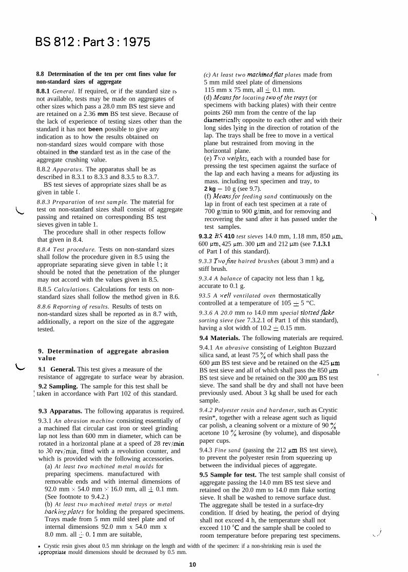
8.8 Determination of the ten per cent fines value fornon-standard sizes of aggregate8.8.1 General. If required, or if the standard size ISnot available, tests may be made on aggregates ofother sizes which pass a 28.0 mm BS test sieve andare retained on a 2.36 mm BS test sieve. Because ofthe lack of experience of testing sizes other than thestandard it has not been possible to give anyindication as to how the results obtained onnon-standard sizes would compare with thoseobtained in the standard test as in the case of theaggregate crushing value.
8.8.2 Apparatus. The apparatus shall be asdescribed in 8.3.1 to 8.3.3 and 8.3.5 to 8.3.7.
BS test sieves of appropriate sizes shall be asgiven in table 1.
8.8.3 Preparation of test sample. The material for
L test on non-standard sizes shall consist of aggregatepassing and retained on corresponding BS testsieves given in table 1.
The procedure shall in other respects followthat given in 8.4.
8.8.4 Test procedure. Tests on non-standard sizesshall follow the procedure given in 8.5 using theappropriate separating sieve given in table 1; itshould be noted that the penetration of the plungermay not accord with the values given in 8.5.
8.8.5 Calculations. Calculations for tests on non-standard sizes shall follow the method given in 8.6.
8.8.6 Reporting of results. Results of tests onnon-standard sizes shall be reported as in 8.7 with,additionally, a report on the size of the aggregatetested.
9. Determination of aggregate abrasionvalue
L 9.1 General. This test gives a measure of theresistance of aggregate to surface wear by abrasion.
9.2 Sampling. The sample for this test shall be: taken in accordance with Part 102 of this standard.
9.3 Apparatus. The following apparatus is required.
9.3.1 An abrasion machine consisting essentially ofa machined flat circular cast iron or steel grindinglap not less than 600 mm in diameter, which can berotated in a horizontal plane at a speed of 28 reviminto 30 revimin. fitted with a revolution counter, andwhich is provided with the following accessories.
(a) At least tn.0 machined metal moulds forpreparing specimens. manufactured withremovable ends and with internal dimensions of92.0 mm x 54.0 mm x 16.0 mm, all 4 0.1 mm.(See footnote to 9.4.2.)(b) At least t1i.o machined metal trays or metalbackingplates for holding the prepared specimens.Trays made from 5 mm mild steel plate and ofinternal dimensions 92.0 mm x 54.0 mm x8.0 mm. all + 0. I mm are suitable,
(c) At least two machinedSPat plates made from5 mm mild steel plate of dimensions115 mm x 75 mm, all 5 0.1 mm.(d) Means,for locating two of’the trals (orspecimens with backing plates) with their centrepoints 260 mm from the centre of the lapdiametricallv opposite to each other and with theirlong sides lying in the direction of rotation of thelap. The trays shall be free to move in a verticalplane but restrained from moving in thehorizontal plane.(e) TWO neighrs, each with a rounded base forpressing the test specimen against the surface ofthe lap and each having a means for adjusting itsmass. including test specimen and tray, to2 kg = 10 g (see 9.7).(f) Means+for feeding sand continuously on thelap in front of each test specimen at a rate of700 gimin to 900 gimin, and for removing andrecovering the sand after it has passed under thetest samples.
9.3.2 BS 410 test sieves 14.0 mm, 1.18 mm, 850 urn,600 urn, 425 urn. 300 urn and 212 pm (see 7.1.3.1of Part 1 of this standard).
9.3.3 Twojine haired brushes (about 3 mm) and astiff brush.
9.3.4 A balance of capacity not less than 1 kg,accurate to 0.1 g.
93.5 A well ventilated oven thermostaticallycontrolled at a temperature of 105 5 5 “C.
9.3.6 A 20.0 mm to 14.0 mm special slottedfikesorting sieve (see 7.3.2.1 of Part 1 of this standard),having a slot width of 10.2 5 0.15 mm.
9.4 Materials. The following materials are required.
9.4.1 An abrasive consisting of Leighton Buzzardsilica sand, at least 75 % of which shall pass the600 urn BS test sieve and be retained on the 425 urnBS test sieve and all of which shall pass the 850 urnBS test sieve and be retained on the 300 nm BS testsieve. The sand shall be dry and shall not have beenpreviously used. About 3 kg shall be used for eachsample.
9.4.2 Polyester resin and hardener, such as Crysticresin*, together with a release agent such as liquidcar polish, a cleaning solvent or a mixture of 90 %acetone 10 % kerosine (by volume), and disposablepaper cups.
9.4.3 Fine sand (passing the 212 brn BS test sieve),to prevent the polyester resin from squeezing upbetween the individual pieces of aggregate.
9.5 Sample for test. The test sample shall consist ofaggregate passing the 14.0 mm BS test sieve andretained on the 20.0 mm to 14.0 mm flake sortingsieve. It shall be washed to remove surface dust.The aggregate shall be tested in a surface-drycondition. If dried by heating, the period of dryingshall not exceed 4 h, the temperature shall notexceed 110 “C and the sample shall be cooled toroom temperature before preparing test specimens.
l Crystic resin gives about 0.5 mm shrinkage on the length and width of the specimen: if a non-shrinking resin is used theappropriate mould dimensions should be decreased by 0.5 mm.
10

BS812:Part3:1975
9.6 Preparation of test specimen. Two specimens aggregates may visibly score the machined surfaceshall be made for each test. As many particles as of the grinding lap, in which case the surface shallpossible from the test sample, but in any case not be remachined.less than 24, shall be placed in the mould in a single Immediately screen the sand on the 1.18 mm BSlayer with their flattest surface lying on the bottom test sieve and re-use it as many times as is necessaryof the mould. to complete the test and then discard it.
The particles may be selected from the test sample On completion of 500 revolutions remove theas required but care shall be taken to ensure that test specimens from the machine, remove the traysthey are representative of the test sample. or backing plates and weigh the specimens to the
The interstices between the pieces of aggregate nearest 0.1 g (mass B).shall then be filled to approximately three quarters 9.8 Calculations. The aggregate abrasion value ofof their depth with the fine sand which shall then be each test specimen shall be calculated as follows.levelled with one fine haired brush. The exposedinternal faces and top edges of the mould shall be 3 (A - B)
lightly coated with release agent with the second dfine haired brush. Sufficient resin and hardener shall wherethen be mixed in a disposable cup and used to fU A is the mass of specimen before abrasion (g);the mould to overflowing. B is the mass of specimen after abrasion (g) ;NOTE. Approximately equal proportions of resin and d is the relative density of sample (on saturatedhardener have been found to be suitable when using Crystic surface-dried basis) as determined in clause 5 Iresin. of Part 2 of this standard.
One side of the flat plate shall then be coated withthe release agent and it shall be placed firmly on the
NOTE. The calculation is based on the percentage loss inmass of an assumed 33 ml volume of aggregate.
mould coated side down and held in position by aweight of not less than 2 kg. When the resin has
9.9 Reporting of results. The mean of the two
hardened (usually after 30 min) the plate shall beresults shall be reported to two significant figures as
removed and excess resin trimmed off with a knifethe aggregate abrasion value, unless the individual
or spatula. The specimen shall then be removedresults differ from the mean of the two results by
from the mould, the loose sand removed with themore than 10 ‘A of the mean value. In this case the
stiff brush and the specimen then weighed to thetest shall be repeated and the mean of the four tests
nearest 0.1 g (mass A).shall be reported as the aggregate abrasion value.
NOTE. The solvent should be used to clean moulds, tools,etc., as required. 10. Determination of the polished-stone
value9.7 Test procedure. Fit each specimen into one ofthe machined metal trays or metal backing plates, 10.1 General. The polished-stone value gives ataking care to ensure a tight fit. Weigh each measure of the resistance of roadstone to thespecimen in its tray with one of the weights whose polishing action of a pneumatic tyre undermass shall then be adjusted until the total is conditions similar to those occurring on the surface2 kg i 10 g. Place the two specimens in the of a road. Where the surface of a road consistsabrasion machine diametrically opposite to each largely of roadstone the state of polish of the sampleother with their centre points 260 mm from the will be one of the major factors affecting thecentre of the lap and ro that the 92 mm x 54 mm resistance of the surface to skidding. The actualface of exposed aggregate particles rests on the lap relationship between polished-stone value andover the whole face area; then place the appropriate skidding resistance will vary with the trafficweights centrally on the specimens. Then turn the conditions, type of surfacing and other factors. Alllap through 500 revolutions at a speed of 28 rev/min factors together with the reproducibility of the testto 30 revimin, the abrasive sand specified above should be taken into account when drawing upbeing fed continuously on to it across the full width specifications for roadworks which include testof the specimen immediately in front of each test limits for polished-stone value. The test is in twospecimen at a rate of 700 g/min to 900 g/min per parts.specimen*. To ensure that the sand is fed beneath (a) First part. Samples of stone are subjected toeach specimen lift them clear of the lap for I an accelerated polishing action in a specialrevolution before the start of abrasion and at every machine. Two methods are given for mountinghundredth revolution thereafter. Remove the sand the sample for polishing.with a rubber edged blade, mounted so that the (b) Secondpart. The state of polish reached byrubber edge rests lightly on the lap for its full width, each sample is measured by means of a suitable
and collect it. friction test and is expressed as a laboratoryIf it becomes apparent that, because of the nature determined polished-stone value.
of the aggregate, it has abraded away to the level of 10.2 Sampling. The sample for this test shall bethe resin backing discontinue the test. Report the taken in accordance with Part 102 of this standard. Inumber of revolutions. Conversely, some very hard
l A slot of about 1.3 mm width is suitable.
11

BS812:Part3: 1975
10.3 Apparatus*. The following apparatus isrequired.
10.3.1 An acceleratedpolishing machine which shallbe rigidly mounted on a firm, level base of stone orconcrete and shall include the following.
(a) A wheel (referred to below as the ‘road wheel’)having a flat periphery, and of such a size andshape as to permit fourteen of the specimensdescribed below to be clamped on the peripheryso as to form a continuous surface of stoneparticles 45 mm wide and 406 mm in diameter.(b) Means qf rotating the road wheel about its ownaxis at a speed of 3 15 rev/min to 325 revjmin.(c) Means qf bringing the surface of a rubbertyred wheel of 203 mm diameter and 50 mmbreadth to bear on the stone surface of the roadwheel with a total force of 390 i 5 N. The tyreshall be an industrial 8 x 2 pneumatic 2-plyrating smooth hand-truck tyre, specially selectedand if necessary treated to obtain a true runningsurface. The tyre shall have a hardness of55 5 5 IRHDt and shall be inflated to a pressureof310 5 15 kNim2; it shall be free to rotateabout its own axis, which shall be parallel withthe axis of the road wheel, and the plane ofrotation of the tyre shall be in line with that ofthe road wheel.
It is important that the machine shall beaccurately aligned and that both wheels shall befree to rotate without play in the bearings. Thefollowing limits shall be applied:
The planes of rotation of the two wheels shallbe not more than 20 minutes of arc out of parallel(1 mm in 200 mm).
The planes through the centres of the twowheels shall be not more than 0.8 mm apart.(d) Means to feed the corn emery specified in10.4.1 and water at the rates shown in 10.7 andin such a \vay that the emery and water arecontinuously and uniformly spread over thesurface of the tyre and the specimens where theyare in contact. The emery and water shall be feddirectly on to the road wheel near the point ofcontact with the rubber tyred wheel.(e) Means to feed the emerJ*.flour specified in10.4.2 and water at the rates shown in 10.7 andin such a way that the emery flour and water arecontinuously and uniformly spread over thesurface of the tyre and the specimens where theyare in contact.
NOTE. A separate feed mechanism for each abrasive isrecommended to avoid excessive readjustment.
10.3.2 A number qf accurateIF machined metalmoulds for preparing specimens of the dimensionsspecified in 10.5.
10.3.3 A friction tester complying with therequirements set out in 10.8 and 10.9.
10.3.4 BS 410 test sieves of the following sizes:10.0 mm, 600 pm, 500 Mm, 425 pm, 355 pm, 300 gm,
212 pm and 53 pm (see 7.1.3.1 of Part 1 of this standard).
10.3.5 A 14.0 mm to 10.0 mm special slotted fikesorting sieve (see 7.3.2.1 of Part 1 of this standard),having a slot width of 7.2 = 0.1 mm.
10.4 Materials. The following materials arerequired.
10.4.1 A suppI offresh natural corn emer!,, whichshall be used only once, complying with thefollowing grading requirements:
Nominal width of Total percentageaperture passing
pm600 98 to 100500 70 to 100425 30 to 90355 oto30300 Oto5
10.4.2 A supply of air-floated emerijour the wholeof which shall pass a 53 pm BS test sieve.NOTE. Additional apparatus and materials are specified inthe subclause for each mounting method (10.51 and 10.52).
10.5 Preparation of specimens
10.5.1 General. At least 3 kg of nominal 10 mmparticles shall be available for each sample to betested. The particles actually used in the preparationof the test specimens shall all pass the 10.0 mmBS test sieve and be retained on the 14 mm to10 mm flake sorting sieve. They shall not beelongated and shall be clean and free from dust.
A representative sample shall be obtained by themethod described in 5.2.2 of Part 1 of this standardfrom the normal run of production from the plant,since chippings that have been freshly crushed inthe laboratory may give misleadingly high results.The surface texture of the particles which are to beexposed to the polishing action of the tyre shall berepresentative of the average surface texture of thestone; a few particles having a very smooth or veryrough surface texture may occur in almost anysample, but these shall not be used in preparing thetest specimen.
Each specimen shall consist of a single layer of35 to 50 of the particles, placed as closely as possibleand covering an area of 90.6 mm x 44.5 mm, setin a sand-cement mortar or a resin as describedin 10.5.2 or 10.5.3 respectively with their exposedsurfaces proud of the backing. The surface of thespecimen shall be flat across the shorter dimensionbut shall be curved in the arc of a circle of 406 mmdiameter along the longer dimension.
The finished specimen shall present the naturalsurface of the stone chippings with no sharpprojecting edges to the polishing tyre and shall benot less than 12.5 mm thick; the under surface shallbe the arc of a circle of exactly the same diameteras the periphery of the road wheel of the polishingmachine. Four specimens shall be made from eachmaterial to be tested.
l Where necessary, information on the current sources of supply of any of the apparatus or materials required for this test can beobtained from the Transport and Road Research Laboratory, Old Wokingham Road, Crowthorne, Berks. RGI 1 6AU.
t BS 27 19 gives methods of testing hardness by means of pocket type rubber hardness meters. The revision of the standard, whichis in course of preparation, specifies hardness in terms of international rubber hardness degrees (IRHD) which have the samevalues as the obsolete British Standard rubber hardness degrees.
12

BS812:Part3: 1975
l rL, �
10.5.2 Sand-cement mortar specimens. Thefollowing apparatus and materials are required.
(a) Fine sand all passing a 212 pm test sieve.(b) Iron wire (approximately 1.2 mm diameter).Three approximately 75 mm lengths are requiredfor each specimen. Straightened large paper-clipsare satisfactory.(c) High alumina cement (see BS 915).(d) A water spray.(e) A spatula.(f) A stiff bristle brush.k> A tray.The specimen shall be prepared by carefully
placing 35 to 50 selected particles in a single layerwith their flattest surfaces lying on the bottom ofthe mould. The interstices between the particlesshall then be filled to one quarter to a half of theirdepth with fine sand (all passing a 212 pm BS testsieve), the sand wetted thoroughly with a fine sprayof water, three pieces of 1.2 mm iron wire laid alongthe longer dimension to act as reinforcement* andthe mould filled to overflowing with a mortar madefrom equal portions by mass of sand passing a212 pm BS test sieve and high alumina cement; theconsistency of the mortar shall be such as to permit itto flow freely between the particles. The mouldshall then be left until the mortar has stiffenedsufficiently to be struck off accurately level with thecurved sides of the mould (usually between 3 h and6 h). The specimen shall then be left in the mould,covered by a water-saturated cloth, for a further24 h, after which it shall be removed from themould and the loose sand brushed free with thestiff bristle brush. The specimen shall be storedunder water with the stone surface downwards for7 days to 14 days.10.53 Resin specimens. The following apparatusand materials are required.
(a) Release agent or liquid car polish.(b) Cleansing solvent or a mixture of 90 %acetone and 10 % kerosine (by volume).(c) Polyester resin and hardener, such as Crysticresin.(d) Disposable paper cups.(e) Clearflexibleylastics sheet such as acetate orpolyethylene sheet.(f) A metalplate shaped to the radius (189 mm)oi‘the polishing test mould and a little largerthan the mould.(g) A 2 kg weight or a clamp.(h) Twofine haired brushes (about 3 mm).(i) A stiffbristle brush.(j) A spatula.The specimen shall be prepared by carefully
placing 35 to 50 selected particles in a single layerwith their flattest surfaces lying on the bottom of themould. The interstices between the particles shallthen be filled to approximately three quarters oftheir depth with fine sand (all passing a 212 pmBS test sieve) which shall then be levelled with one
tie haired brush. The exposed internal faces andtop edges of the mould shall be lightly coated with.release agent using the second fine haired brush.The hardener shall be mixed with the resin in adisposable cup; the exact proportion is not criticaland depends upon the resin used.NOTE. Approximately equal proportions of the twocomponents have been found to be suitable when usingCrystic resin.
The mould shall be filled to overflowing with themixed resin and when it has reached a suitableconsistency the surplus shall be floated off with thespatula without disturbing the main body of theresin.NOTE. Alternatively the surplus may be squeezed out bycovering the mould with the plastics sheet and pressing themetal plate on to the sheet.
When the resin commences to harden (after5 min to 10 min) any excess resin shall be trimmedfrom the edges with a knife and the metal plate shallbe pressed to the back of the specimen by means ofthe weight (2 kg minimum) or the clamp, to preventdistortion during setting. After the resin hascompletely set and cooled (about 30 min frommixing) the specimen shall be removed from themould and the loose sand removed with the stiffbristle brush, and after a further 30 min may besubjected to the polishing procedure. The solventshould be used to clean moulds, tools, etc., asrequired.10.6 Calibration of the polishing machine. Before anew tyre is used on a test it shall be given apreliminary run of 3 h with corn emery, and 3 h withemery flour, as in an actual test but using spare?specimens, two of which shall be unpolishedEnderby specimens, (see also 10.5). Followingpolishing, the Enderby specimens shall be tested inthe standard manner and the mean result recorded.If this result is greater than 54 the above procedureshall be repeated using further pairs of unpolishedEnderby specimens until the mean result obtainedfalls in the range of 48 to 54. If, in the first instance,the mean figure obtained with the Enderby speci-mens falls below 48 the tyre shall be discarded.Following the above conditioning, the tyre shallbe used for test runs until either it is apparent thatits use for a further run will give a mean figure ofless than 48 with the Enderby specimens or itshows signs of irregular or excessive wear. Thetyre shall not be used for more than 20 runs.
As a check on results, two freshly preparedspecimens of stone from Enderby Quarry,Leicestershire, shall be included in each test run.The mean value for these two specimens shall lie inthe range 48 to 54. If this is not the case then thecomplete test shall be rejected and the whole testprocedure shall be examined and any necessarymodifications made so as to ensure that the meanvalue given by two specimens of stone fromEnderby Quarry lies within the range 48 to 54.-.~
LJ l The reinforcement may be inserted after the mortar has been placed, but if this is done great care will be necessary toavoid disturbance of the chippings.
It Specimens that have been used in earlier tests are suitable.
13

BS812:Part3:1975
10.7 Accelerated polishing of specimens. Thetemperature of the room in which the acceleratedpolishing is carried out shall be 20 + 5 “C.
Fourteen specimens shall be numbered asfollows :
four specimens of I st sample shall be numbered1 to4,four specimens of 2nd sample shall be numbered5 to 8*,four specimens of 3rd sample shall be numbered9 to 12*,two specimens of Enderby control shall benumbered 13 and 14,,
and then arranged in the following order:13.4.5,8.7,1,10,14,3,11,12,2,6,9.The fourteen specimens shall be clamped in the
specified order round the periphery of the roadwheel of the polishing machine, strips ofpolyethylene 0.25 mm thick being inserted betweenadjacent specimens and between the underside ofthe specimens and the periphery of the wheel wherenecessary. The outer surface of the specimens shallform a continuous strip of particles with a peripheryof 406 mm diameter, upon which the pneumatictared wheel shall ride freely without bumping orsiipping. Any gaps shall be filled with a suitablepacking piece level with the remainder of thespecimen.
The road wheel shall then be brought to a speedof 315 revlmin to 325 rev/min and the pneumatictyred wheel shall be brought to bear on the surfaceof the specimens with a total force of 390 & 5 N.Water and the corn emery specified in 10.4.1 shallbe fed continuously on to the road wheel at rateswithin the following limits for a period of3 h i 1 min.
Rate of feedCorn emeryWater
20 g/min to 35 g/minThe water shall be fed at arate just sufficient to carrythe corn emery to the wheel;this is approximately thesame rate as for the cornemery.
The run shall be interrupted after 2 h and theused corn emery removed from the base.
On completion, i.e. after 3 h, the machine andspecimens shall be thoroughly cleaned by washingso that all trace of the corn emery is removed. Themachine shall subsequently be operatedcontinuously for a further 3 h i 1 min as describedin the preceding paragraphs, except that in place ofthe corn emery the flour specified in 10.4.2 shall befed continuously with water at rates within thefollowing limits:
Rate of feed
Emery flourWater
2 g/min to 4 g/min.The rate of feed of thewater shall be twice thatof the emery flour.
The specimens shall then be removed from themachine and shall be thoroughly washed in runningwater to remove all trace of the emery flour. Emeryflour which almost invariably packs in the intersticesbetween the stone particles shall be removed byscrubbing with a stiff bristle brush. The slightesttrace of emery flour on or between the stoneparticles will cause a lowering of the result of thefriction test.
After washing, the specimens shall be stored facedownwards under water at a temperature of 18 “Cto 22 “C for a period of between t h and 2 h andimmediately on removal from the water shall betested on the friction tester as described below. Atno time prior to this testing shall the specimens beallowed to dry out.
10.8 Friction tester. The friction test shall be madewith a tester constructed in accordance withdrawings supplied by the TRRLt. All bearings andworking parts of the instrument shall be enclosedas far as possible, and all materials used shall besuitably treated to prevent corrosion under wetconditions.
The tester shall provide the following.(a) A spring loaded rubber slider of the mass, sizeand shape specified below mounted on the end ofa pendulum arm so that the sliding edge isapproximately 510 mm from the axis ofsuspension.(b) Means for setting the column of the instrumentvertical.(c) Means.for rigidly locating one of the curvedspecimens from the accelerated polishing machinewith its longer dimension in the track of thependulum and centrally with respect to therubber slider and to the axis of suspension of thependulum.(d) Means for raising and lowering the axis ofsuspension of the pendulum so that the slider can
(1) swing clear of the surface of the specimen,and(2) be set to slide over a fixed length ofsurface of 76.0 mm as near as is visuallypossible but in any case within f 0.5 mm.
(e) Means for holding and releasing the pendulumarm so that it falls freely from a horizontalposition.(f) A pointer balanced about the axis ofsuspension, indicating the position of thependulum arm throughout its forward swing andmoving over the circular scale drawn up asspecified in 10.9. The mass of the pointer shall benot more than 85 g and the friction in the pointermechanism shall be adjustable so that, with thependulum arm swinging freely from a horizontalposition, the outward tip of a 300 mm longpointer may be brought to rest on the forwardswing of the arm at a point 10 mm below thehorizontal.
\ *These may be replaced by spare specimens if less than three samples are to be polished.
It Drawings and instructlons, tmalized in March 1960, may be obtained from the Transport and Road ResearchLaboratory, Old Wokingham Road, Crowthorne, Berks. RGll 6AU.
14

BS812:Part3:1975
The mass of the swinging arm including the slidershall be 1.50 & 0.03 kg the centre of gravity lying onthe axis of the arm at a distance of 410 & 5 mmfrom the centre of suspension.
The slider shall consist of a rubber pad 31.75 mmwide, 25.4 mm deep and 6.35 mm thick held on arigid base with a total mass of 20 f 5 g which ismounted on an axis set at an angle of approxi-mately 26 ’ with the horizontal when the pendulumis at the lowest point of its swing, so that only therear edge of the slider contacts the test surface, andthe slider can turn about its axis without obstructionto follow unevenness of the surface perpendicularto the plane of the pendulum swing.
The slider shall be spring loaded against the testsurface and the nominal static force on the slider asset by the procedure defined in the instructionssupplied with the drawings shall be 22.2 f 0.5 N inits median position; the change in the static force onthe slider shall be not greater than 0.2 N permillimetre deflection of the slider.
The slider shall comply with the requirementsgiven in table 2.
The working edges of the slider shall be squareand clean cut, and the rubber free from contamina-tion (abrasive or oil, etc.). No slider shall be usedwhich is more than a year old.
The rubber in the sheet or slider form shall bestored in the dark at a temperature between 10 “Cand 20 “C.10.9 Calibration of the tester. The calibration of thetester shall be checked at least once a year*. Thescale+ of the instrument when used for this testshall be the unit F drawn up by means of thefollowing equation :
w x zF=-PDP
x 100
whereF is a measure of the coefficient of friction
(times 100) ;W is the force exerted by the swinging arm (N);A’ is the distance of the effective centre of gravity
of the arm from the centre of oscillation (mm);2 is the vertical distance of the edge of the scale
below the zero of the scale, which shall be
Table 2. Properties of slider
10 mm below the horizontal when the arm isreleased to swing freely from the horizontal,(mm> ;
P is the nominal static force on the slider (N), asdefined in 10.8;
D is the sliding distance (mm) ;p is the length of the pointer (mm).The instrument shall be cross-checked using the
sliding length of 126 mm with the BSI standardfriction tester on the following wetted surfaces:
(a) a glass plate;(b) five smooth-looking surfaces having atexture depth less than 0.25 mm and covering arange of at least 25 to 75 units;(c) five rough-looking surfaces having a texturedepth greater than 0.50 mm and covering a rangeof at least 35 to 70 units.On these tests no pairs of results obtained with
the two instruments on any surface shall differ bymore than 3 units and the mean results for the 11samples shall not differ by more than 1.5 units.
10.10 Friction test procedure. Make the test at atemperature of 20 & 2 “C and place the apparatus(including slider) in the room for at least 2 h beforethe tests commence, so that it may attain thistemperature.
Rest the tester upon a firm level surface andadjust the levelling screws so that the column isvertical. Then raise the axis of suspension of thependulum so that the arm swings freely, and adjustthe friction in the pointer mechanism so that whenthe pendulum arm and pointer are released fromthe right-hand horizontal position the pointercomes to rest at the zero position on the scale.
Each rubber slider edge may be used for a periodof up to one year (when it should be discarded)provided the following procedure is adopted.
(a) Maintain a stock of Criggion specimens forcontrol purposes. These shall be made from stonefrom Criggion Quarry and shall be made andpolished as in an actual determination. Whentested they shall yield a value in the range 59 to66. Record the values and air-dry the specimensand store them in a sealed container for futureuse.
I * The selection and testing of the rubber for the slider, and the calibration of the tester, are carried out at the BSI TestHouse, Hemel Hempstead Centre, Maylands Avenue, Hemel Hempstead, Herts.? An auxiliary scale is required for this test, because of the shorter sliding distance (76 mm) as compared with the longerdistance (126 mm) used for checking and road testing.: Liipke rebound test in accordance with BS 903:Part A8.3 International rubber hardness degrees in accordance with BS 903:Part ~26.
15

L
L
BS812:Part3:1975
(b) Before being brought into use ‘condition’ anew slider by swinging it five times over the drysurface of a polished Criggion specimen followingwith a further 20 swings on its wetted surface.Keep the Criggion specimen used for thispurpose apart from the Criggion controlspecimens described in (a); it may be usedrepeatedly provided its value (when wet) doesnot fall below 55.Cc) Before each set of measurements, check theslider by testing a Criggion control specimen andrecord the resulting value. Additional polishingthrough repeated testing yields progressivelylower values and the control shall be discardedwhen its value falls below 59 and a new controldrawn from the stock. If a check value is morethan 2 units lower (or one unit higher) than thelast recorded value for the control, discontinuetesting until the reason has been traced and anyfault rectified. A fault could lie in the instrumentor its operation or because of changes in theslider. It is recommended that more than oneslider be kept in use to facilitate differentiationbetween a faulty slider and a defective instrument.(d) A slider that develops excessive burring andscoring through prolonged use can lead tounsatisfactory results. which are usually high,and shall be rejected.Then rigidlv locate the first test specimen with its
longer dimension lying in the track of the pendulum,and centrally with respect to the rubber slider andto the axis of suspension of the pendulum, and insuch a way that the slider of the pendulum willtraverse it in the same direction as it has beentrafficked in the polishing machine.NOTE. For this purpose it is advisable to mark onelongitudinal edge of each specimen. If this mark is on the sideof the specimen furthest from the operator during polishing,it should bc nearest to him durmp testing and vice versa.
Then adjust the height of the axis of suspension ofthe pendulum so that in traversing the specimen therubber slider is in contact with it over the wholewidth of the slider and over a length of 76.0 mm asnear as visually possible but in any case within+ 0.5 mm. Then wet the surfaces of the specimenand the rubber slider with a copious supply of cleanwater, care being taken not to disturb the sliderfrom its set position. Then release the pendulumand pointer from the horizontal position and notethe reading of the pointer. Carry out this operationfive times, re-wetting the specimen each time, andrecord the mean of the last three readings to thenearest whole number.
Test the specimens in the following order:13, 1,3,5,7,9, 11, 12, 10,8,6,4,2, 14.
10.11 Calculations. The mean and range of therecorded values of the four specimens shall becalculated and recorded to the nearest wholenumber.
The mean of the recorded values of the two
/-.3
Enderby control specimens shall be calculated andrecorded to the nearest 0.5 unit.If the range of the values of the four specimens isgreater than 5 units or if the mean value of thecontrol specimens, without further rounding,does not lie within the range 48 to 54, the testresults shall be rejected and the whole test procedureshall be examined and any necessary modificationsmade to ensure that these requirements for rangeand mean are satisfied.
If the range of the values of the four specimens is5 units or less and the mean value of the controlspecimens, without further rounding, lies withinthe range 48 to 54, the polished-stone value shallthen be obtained from the mean value of the fourspecimens and the mean value of the controlspecimens by reference to table 3.10.12 Reporting of results. The polished-stonevalue* obtained from table 3 shall be reported.
* This is not, and should not be confused with, the sideway force coefficient nor with the ‘skid-resistance’ value determinedon a road.
16

BS812:Part3: 1975
Table 3. Calculation of PSV
Enderbycontrolvalue
M&Xlmeasured
:424344
4546
ii49
808182
t
t8 148.5149 49.5 /IO 150.5 51 51.5 I52 152.5 153 53.5 54
kilue to be reported
--
22
271
:
L
L
L
L
1
‘
‘
1
1
,,,,
-
_-
:
223
i
i3
3
3
a4
444
4L
‘
LL‘
;
1
;
t
I
I
I,,/
-
:6:7181910
1213i415I6
j354S5S6Sl
7980
i:83
84
Liz8-l88
a7
f0
.l
1:4r5
I6I7
Iii0
i2 ili3 i2i4 i3i5 i4i6 i5
i7 i6W i759 i8a i951 a
52S3545556
il52535455
77
::8081
8283
it87
-
--
:
:
2
2
2
:3
3
:
:
i
:
4
4
:44
4L
L
;
,
-
17
BS812:Part3:1975
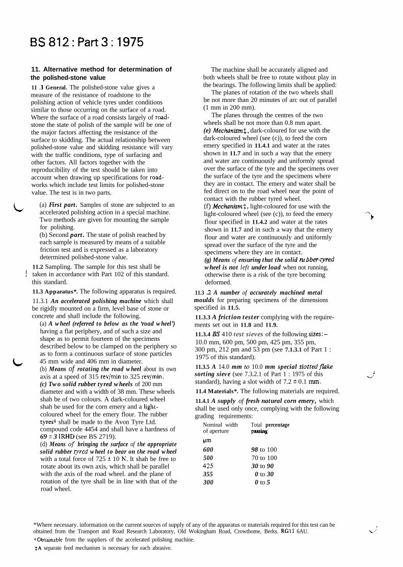
11. Alternative method for determination ofthe polished-stone value
11 .l General. The polished-stone value gives ameasure of the resistance of roadstone to thepolishing action of vehicle tyres under conditionssimilar to those occurring on the surface of a road.Where the surface of a road consists largely of road-stone the state of polish of the sample will be one ofthe major factors affecting the resistance of thesurface to skidding. The actual relationship betweenpolished-stone value and skidding resistance will varywith the traffic conditions, type of surfacing andother factors. All factors together with thereproducibility of the test should be taken intoaccount when drawing up specifications for road-works which include test limits for polished-stonevalue. The test is in two parts.
L(a) First part. Samples of stone are subjected to anaccelerated polishing action in a special machine.Two methods are given for mounting the samplefor polishing.(b) Second part. The state of polish reached byeach sample is measured by means of a suitablefriction test and is expressed as a laboratorydetermined polished-stone value.
!11.2 Sampling. The sample for this test shall betaken in accordance with Part 102 of this standard.this standard.
11.3 Apparatus*. The following apparatus is required.
11.3.1 An accelerated polishing machine which shallbe rigidly mounted on a firm, level base of stone orconcrete and shall include the following.
(a) A wheel (referred to below as the ‘road wheel’)having a flat periphery, and of such a size andshape as to permit fourteen of the specimensdescribed below to be clamped on the periphery soas to form a continuous surface of stone particles
L 45 mm wide and 406 mm in diameter.(b) Means of rotating the road wheel about its ownaxis at a speed of 315 rev/min to 325 rev/min.(c) Two solid rubber tyred wheels of 200 mmdiameter and with a width of 38 mm. These wheelsshah be of two colours. A dark-coloured wheelshah be used for the corn emery and a light-coloured wheel for the emery flour. The rubbertyrest shall be made to the Avon Tyre Ltd.compound code 4454 and shall have a hardness of69 t 3 IRHD (see BS 2719).(d) Means of bringing the surface of the appropriatesolid rubber tyred wheel to bear on the road wheelwith a total force of 725 f 10 Ii. It shah be free torotate about its own axis, which shall be parallelwith the axis of the road wheel. and the plane ofrotation of the tyre shall be in line with that of theroad wheel.
The machine shall be accurately aligned andboth wheels shall be free to rotate without play inthe bearings. The following limits shall be applied:
The planes of rotation of the two wheels shallbe not more than 20 minutes of arc out of parallel(1 mm in 200 mm).
The planes through the centres of the twowheels shall be not more than 0.8 mm apart.(e) Mechanism$, dark-coloured for use with thedark-coloured wheel (see (c)), to feed the cornemery specified in 11.4.1 and water at the ratesshown in 11.7 and in such a way that the emeryand water are continuously and uniformly spreadover the surface of the tyre and the specimens overthe surface of the tyre and the specimens wherethey are in contact. The emery and water shall befed direct on to the road wheel near the point ofcontact with the rubber tyred wheel.(f) Mechanism$, light-coloured for use with thelight-coloured wheel (see (c)), to feed the emeryflour specified in 11.4.2 and water at the ratesshown in 11.7 and in such a way that the emeryflour and water are continuously and uniformlyspread over the surface of the tyre and thespecimens where they are in contact.(g) Means of ensuring that the solid no bber-tyredwheel is not left under load when not running,otherwise there is a risk of the tyre becomingdeformed.
11.3 3 A number of accurately machined metalmoulds for preparing specimens of the dimensionsspecified in 11.5.
11.3.3 A friction tester complying with the require-ments set out in 11.8 and 11.9.
11.3.4 BS 410 test sieves of the following sizes:-10.0 mm, 600 pm, 500 pm, 425 pm, 355 pm,300 pm, 212 pm and 53 pm (see 7.1.3.1 of Part 1 :1975 of this standard).
11.3.5 A 14.0 mm to 10.0 mm special slottedfikesorting sieve (see 7.3.2.1 of Part 1 : 1975 of thisstandard), having a slot width of 7.2 f 0.1 mm.
11.4 Materials*. The following materials are required.
11.4.1 A supply of fresh natural corn emery, whichshall be used only once, complying with the followinggrading requirements:
Nominal width Total percentageof aperture pnssins
pm600 98 to 100500 70 to 100425 30 to 90355 0 to 30300 0 to 5
*Where necessary. information on the current sources of supply of any of the apparatus or materials required for this test can beobtained from the Transport and Road Research Laboratory, Old Wokingham Road, Crowthome, Berks. RGll 6AU.+Obtainablc from the suppliers of the accelerated polishing machine.$A separate feed mechanism is necessary for each abrasive.
,.:

! ,
BS812:Part3:1975
r 11.43 A supply of air-floated or water-washedemery flour the whole of which shah pass a 53 pm BStest sieve when tested according to the decant&iontest (see 7.2.4 of Part 1 : 1975 of this standard), butusing a 53 pm test sieve instead of the 75 pm sieveused in the procedure specified in Part 1.11.43 A supply of PSV control stone (see theforeword).
11.4.4 A supply of Criggion stone (see 11.10).NOTE. Additional apparatus and materials are specified inthe subclause for each mounting method (11.5.2 and 11.53).
11.5 Preparations of specimens11.5.1 General. A representative sample shah beobtained by the method described in 5.2.2 of Part 1 :1975 of this standard from the normal run ofproduction from the plant, since chippings that havebeen freshly crushed in the laboratory may givemisleadingly high results.
The particles actually used in the preparation ofA
Lf ’
the test specimens shah all pass the 10.0 mm BS testsieve and be retained on the 14 mm to 10 mm flakesorting sieve. They shah not be elongated and shah beclean and free from dust. The sample shah provide aminimum of 2 kg of material meeting these require-ments.
The surface texture of the particles which are tobe exposed to the polishing action of the tyre shah berepresentative of the average surface texture of thestone; a few particles having a very smooth or veryrough surface texture may occur in almost anysample but these shah not be used in preparing thetest specimen.
Each specimen shah consist of a single layer of 35to 50 of the particles, placed as closely as possibleand covering an area of 90.6 mm x 44.5 mm, set in asand-cement mortar or a resin as described in 11.5.2or 11 S.3 respectively with their exposed surfacesproud of the backing. The surface of the specimenshah be flat across the shorter dimension but shall becurved in the arc of a circle of 406 mm diameteralong the longer dimension.
The finished specimen shah present the naturalsurface of the stone chippings with no sharp project-ing edges to the polishing tyre and shah be not lessthan 12.5 mm thick; the under surface shah be thearc of a circle of exactly the same diameter as theperiphery of the road wheel of the polishing machine.Any specimen with mortar or resin exposed at the.&ace shall be rejected. Four specimens shah bemade from each material to be tested.
11 S.2 Sand-cement mortar specimens. The followingapparatus and materials are required.
(a) Fine sand ail passing a 312 urn test sieve.(b) Iron wire (approximately 1.2 mm diameter).Three approximately 75 mm lengths are requiredfor each specimen. Straightened large paperclipsare satisfactory.
e
(c) High alumina cement (see BS 9 15).(d) A water spmy.(e) A spatula.(f) A stiff bristle brush.69 A tray.The specimen shah be prepared by carefully placing
35 to 50 selected particles in a single layer with theirflattest surfaces lying on the bottom of the mould.The interstices between the particles shah then befilled to between one-quarter and one-half of theirdepth with fine sand (all passing a 212 urn BS testsieve), the sand wetted thoroughly with a fine sprayof water, three pieces of 1.2 mm iron wire laid alongthe longer dimension to act as reinforcement* andthe mould filled to overflowing with a mortar madefrom equal portions by mass of sand passing a 212 urnBS test sieve and high alumina cement; the consistencyof the mortar shah be such as to permit it to flowfreely between the particles. The mould shah then beleft until the mortar has stiffened sufficiently to bestruck off accurately level with the curved sides ofthe mould (usually between 3 h and 6 h).The specimen shah then be left in the mould, coveredby a water-saturated cloth, for a further 24 h, afterwhich it shah be removed from the mould and theloose sand brushed free with the stiff bristle brush.The specimen shah be stored under water with thestone surface downwards for 7 days to 14 days.
11 S.3 Resin specimens. The following apparatus andmaterials are required.
(a) Release agent or liquid car polish.(b) Cleansing solvent or a mixture of 90 70 acetoneand 10 % kerosine (by volume).(c)Polyester resin and hardener, such as Crysticresin.(d) Disposable paper cups.(e) Clearflexible plastics sheet such as acetate orpolyethylene sheet.(f) A pair of rigzii metal covers having one faceplane, the other shaped to the radius (189 mm)of the polishing test mould and a little larger thanthe mould.(g) A cZamp, such as a 200 mm G-clamp.(h) Two fine haired brushes (about 3 mm).$ i ;fz;s tle brush.
a
The specimen shah be prepared by carefully placing35 to 50 selected particles in a single layer with theirflattest surfaces lying on the bottom of the mould.The interstices between the particles shah then befilled to approximately three-quarters of their depthwith fine sand (ah passing a 212 urn BS test sieve)which shall then be levelled with one fine hairedbrush. The exposed internal faces and top edges ofthe mould shah be lightly coated with release agentusing the second fine haired brush. The hardener shallbe mixed with the resin in a disposable cup; the exactproportion is not critical and depends upon the resinused.
*The reinforcement may be. inserted after the mortar has been placed, but if this is done great care will be necessary to avoid disturbanceof the chippings.
19

BS812:Part3: 1975
The outer surface of the specimens shall form acontinuous strip of particles with a periphery of406 mm diameter, upon which the rubber-tyred wheelshall ride freely without bumping or slipping. Anygaps shall be filled with a suitable packing piece levelwith the remainder of the specimen.
The road wheel shall then be brought to a speed of3 15 rev/min to 325 rev/min and the dark-colouredwheel shall be brought to bear on the surface of thespecimens with a total force of 725 f 10 N. Waterand the corn emery specified in 11.4.1 shall be fedcontinuously on to the road wheel using the dark-coloured feed mechanism at rates within the followinglimits for a period of 3 h f 1 min.
Rate of feedCorn emery 20 g/min to 35 g/minWater The water shall be fed at a rate
just sufficient to carry the cornemery to the wheel; this isapproximately the same rate asfor the corn emery.
The run shall be interrupted after 2 h and the usedcorn emery removed from the base. On completion,i.e. after 3 h, the machine and specimens shall bethoroughly cleaned by washing so that all trace of thecorn emery is removed.
The lightcoloured wheel and emery flour feedmechanism shall next be fitted. The machine shallsubsequently be operated continuously for a further3 h t 1 min as described in the preceding paragraphs,except that in place of the corn emery the flourspecified in 11.4.2 shall be fed continuously withwater at rates within the following limits.
Rate of feedEmery flour 2 g/min to 4 g/minWater The rate of feed of the water
shall be twice that of theemery flour.
It is important that the solid rubber tyred wheel isnot left under load at any time other than when thewheel is running, otherwise there is a risk of the tyrebecoming deformed.
The specimens shall then be removed from themachine and shall be thoroughly washed in runningwater to remove all trace of the emery flour. Emeryflour which almost invariably packs in the intersticesbetween the stone particles shall be removed byscrubbing with a stiff bristle brush. The slightest traceof emery flour on or between the stone particles willcause a lowering of the result of the friction test.
After washing, the specimens shall be stored facedownwards under water at a temperature of 18 “C to32 ‘C for a period of between ?4 h and 2 h andimmediately on removal from the water shall be testedon the friction tester as described below. At no timeprior to this testing shall the specimens be allowed todry out.11.8 Friction tester. The friction test shall be madewith a tester manufactured under licence to the
NOTE. Approximately equal proportions of the twocomponents have been found to be suitable when usingCrystic resin.
The mould shall be filled to overflowing with themixed resin and when it has reached a suitableconsistency the surplus shall be floated off with thespatula without disturbing the main body of the resin.NOTE. Alternatively the surplus may be squeezed out bycovering the mould with the plastic sheet and pressing themetal cover on to the sheet.
When the resin commences to harden (after 5 minto 10 min) any excess resin shall be trimmed from theedges with a knife and the metal cover shall be pressedto the back of the specimen by means of the clamp,to prevent distortion during setting. After the resinhas completely set and cooled (about 30 min frommixing) the specimen shall be removed from the mouldand the loose sand removed with the stiff bristle brush,and after a further 30 min may be subjected to thepolishing procedure. The solvent should be used to
Lclean moulds. tools, etc, as required.
11 S.4 @Airy of specimens. All test specimens shallbe critically examined and any with matrix at thesurface or with disturbed chipping shall be rejected.
11.6 Calibration of the polishing machine. Before anew tyre is used on a test, a preliminary run with theappropriate abrasive shall be made using the newtyre* as in an actual test? but using spare specimens:.(see also 11 S). Following polishing, the controlspecimens shall be tested in the standard manner and
!the mean result recorded. If this result is greater than57 or less than 5 1 this test shall be rejected. and anynecessary modification made so as to ensure that themean value given by the two fresh specimens of the
! control stone lies within the range 51 to 57.I NOTE. More than one preliminary run may be required to/ lower the control values to the permitted ran_ee.
The use of a solid rubber tyre shall be limited to40 runs. and be rejected earlier if showing excessivewear or damage.
L 1 I. 7 Accelerated polishing of specimens. The tem-perature of the room in which the accelerated polish-ing is carried out shall be 20 ? 5 “C.
Fourteen specimens shall be numbered asfollows:
four specimens of I st sample shall be numbered1 t o 4 .
four specimens of 2nd sample shall be numbered5 to 85.four specimens of 3rd sample shall be numbered9 to 12$,two specimens of the PSV control stone shall benumbered 13 and 14,
and then arranged m tne following order:13.4.5,8.7.1~10,14,3.11,12,2.6.9.The fourteen specimens shall be clamped in the
specified order round the periphery of the road wheelof the polishing machine, strips of polyethylene0.25 IIIIII thick being inserted between adjacentspecimens and between the underside of the specimensand the periphery of the wheel where necessary.
*It is es,;ential to use the correct wheel appropriate to each abrasive.
:!I IS eaential that the test includes the use of the other wheel and abrasive as is appropriate to comply with the complete testprocedure.
SSpecimens that have been used in earlier tests are suitable.
~Thcse may be replaced by spare specimens if less than three samples are to be polished.
?
J

c Transport and Road Research Laboratory (TRRL)design. All bearings and working parts of theinstrument shall be enclosed as far as possible, and allmaterials used shall be suitably treated to preventcorrosion under wet conditions.
The tester shall provide the following.(a) A spring loaded rubber slider of the mass, sizeand shape specified below mounted on the end ofa pendulum arm so that the sliding edge isapproximately 5 10 mm from the axis of suspension.(b) Means for setting the column of the instrumentvertical.(c)Means for @idij) locating one of the curvedspecimens from the accelerated polishing machinewith its longer dimension in the track of thependulum and centrally with respect to the rubberslider and to the axis of suspension of thependulum.
(d) Means for raising and lowering the axis ofsuspension of the pendulum so that the slider can
(1) swing clear of the surface of the specimen,
z;]be set to slide over a fixed length of surfaceof 126.0 mm as near as is visually possible butin any case within + 0.5 mm.
(e) Means for holding and releasing the pendulumarm so that it falls freely from a horizontal position.(f) A pointer balanced about the axis of suspension,indicating the position of the pendulum armthroughout its forward swing and moving over thecircular scale drawn up as specified in 11.9.The mass of the pointer shall be not more than85 g and the friction in the pointer mechanismshall be adjustable so that, with the pendulum armswinging freely from a horizontal position,the outward tip of a 300 mm long pointer may bebrought to rest on the forward swing of the arm ata point 10 mm below the horizontal.The mass of the swinging arm including the slider
shall be 1.50 + 0.03 kg, the centre of gravity lying onthe axis of the arm at a distance of 410 f 5 mm fromthe centre of suspension.
The slider shall consist of a rubber pad 3 1.75 mmwide. 35.4 mm deep and 6.35 mm thick held on arigid base with a total mass of 20 f 5 g which ismounted on an axis set at an angle of approximately26” with the horizontal when the pendulum is at thelowest point of its swing, so that only the rear edge of
Table 2. Properties of slider
BS812:Part3:1975
the slider contacts the test surface, and the slider canturn about its axis without obstruction to followunevenness of the surface perpendicular to the planeof the pendulum swing.
The slider shall be spring loaded against the testsurface and the nominal static force on the slider asset by the procedure defined in the instructionssupplied with the drawings shall be 22.2 f 0.5 N in itsmedian position; the change in the static force on theslider shall be not greater than 0.2 N per millimetredeflection of the slider.
The slider sha.ll comply with the requirementsgiven in table 2.
The working edges of the slider shall be square andclean cut, and the rubber free from contamination(abrasive or oil, etc).
The rubber in the sheet or slider form shall bestored in the dark at a temperature between 10 “Cand 20 “C.
11.9 Calibration of the tester. The calibration of thetester shall be checked at least once a year*. The scale?of the instrument when used for this test shall be theunit F drawn up by means of the following equation:
WXZF = - x 1 0 0
PDPwhere
F is a measure of the coefficient of friction(times 100);
W is the force exerted by the swinging arm (N);X is the distance of the effective centre of gravity
of the arm from the centre of oscillation (mm);Z is the vertical distance of the edge of the scaie
below the zero of the scale, which shall be10 mm below the horizontal when the arm isreleased to swing freely from the horizontal(mm);
P is the nominal static force on the slider (N).as defined in 11.8;
D is the sliding distance (mm);p is the length of the pointer (mm).
The instrument shall be crosschecked using thesliding length of 126 mm with the BSI standardfriction tester on the following wetted surfaces:
(a) a glass plate;(b) five smooth-looking surfaces having a texturedepth less than 0.25 mm and covering a range of atleast 25 to 75 units;
Property
Resilience 70%Hardness IRHD§
At temperature CC) of
0 10 20 30 40
43 to 49 58 to 65 66 to 73 71 to 77 74 to 7955 + 5 55 2 5 55 2 5 55 + 5 55 f 5
*The calibration of the tester is carried out at ihe BSI Test House, Hemel Hempstead Centre, Maylands Avenue, Hemel Hempstead, Herts.
iAHem.
i An auxiliary scale is required for this test, because of the shorter sliding distance (76 mm) as compared with the longer distance (126 mm)used for checking and road testing.
$Liipke rebound test in accordance with BS 903 : Part AS.$ International rubber hardness degrees in accordance with BS 903 : part ,426.
21

BS812:Part3:1975
(c) five rough-looking surfaces having a texturedepth greater than 0.50 mm and covering a rangeof at least 35 to 70 units.On these tests no pairs of results obtained with the
two instruments on any surface shall differ by morethan 3 units and the mean results for the 11 samplesshall not differ by more than 1.5 units.
il.10 Friction test procedure. Make the test at atemperature of 20 2 3 “C and place the apparatus(including slider) in the room for at least 2 h beforethe tests commence, so that it may attain thistemperature.
Rest the tester upon a firm level surface and adjustthe levelling screws so that the column is vertical.Then raise the axis of suspension of the pendulum sothat the arm swings freely, and adjust the friction inthe pointer mechanism so that when the pendulumarm and pointer are released from the right-hand’ orizontal position the pointer comes to rest at the
Lro position on the scale.Each rubber slider edge may be used provided the
following procedure is adopted.
c,
(a) Maintain a stock of Criggion specimens forcontrol purposes. These shall be made from stonefrom Criggion Quarry and shall be made andpolished as in an actual determination. When testedthey shall yield a value in the range 59 to 66.Record the values and air-dry the specimens andstore them in a sealed container for future use.(b) Before being brought into use ‘condition’ anew slider by swinging it five times over the drysurface of a polished Criggion specimen followingwith a further 20 swings on its wetted surface.Keep the Criggion specimen used for this purposeapart from the Criggion control specimensdescribed in (a): it may be used repeatedlyprovided its value (when wet) does not fall below55.(c) Before each set of measurements, check theslider by testing a Criggion control specimen andrecord the resulting value. Additional polishingthrough repeated testing yields progressively lowervalues and the control shall be discarded when itsvalue falls below 59 and a new control drawn fromthe stock. If a check value is more than 2 unitslower (or one unit higher) than the last recordedvalue for the control. discontinue testing until thereason has been traced and any fault rectified.A fault could lie in the instrument or its operationor because of changes in the slider. It isrecommended that more than one slider be kept inuse to facilitate differentiation between a faultyslider and a defective instrument.(d) A slider that develops excessive burring andscoring through prolonged use can lead tounsatisfactory results. which are usually high,and shall be rejected.
Then rigidly locate the first test specimen with itslonger dimension lying in the track of the pendulum.and centrally with respect to the rubber slider and tothe axis of suspension of the pendulum, and in such away that the slider of the pendulum will traverse it inthe same direction as it has been trafficked in thepolishing machine.NOTE. For this purpose it is advisable to mark onelongitudinal edge of each specimen. If this mark is on the sideof the specimen furthest from the operator during polishing,it should be nearest to him during friction testing and viceversa.
Then adjust the height of the axis of suspension ofthe pendulum so that in traversing the specimen therubber slider is in contact with it over the whole widthof the slider and over a length of 76.0 mm as near asvisually possible but in any case within + 0.5 mm.Then wet the surfaces of the specimen and the rubberslider with a copious supply of clean water, care beingtaken not to disturb the slider from its set position.Then release the pendulum and pointer from thehorizontal position and note the reading of the pointer.Carry out this operation five times, re-wetting thespecimen each time, and record the mean of the lastthree readings to the nearest whole number.
Test the specimens in the following order:13,1,3,5,7,9,11,12,10,8,6,4,2,14.
11 .l 1 Calculations. The mean and range of therecorded values of the four specimens shah becalculated and recorded to the nearest whole number.
The mean of the recorded values of the two PSVcontrol stone specimens shah be calculated andrecorded to the nearest 0.5 unit.
If the range of the values of the four specimens ofany sample is greater than 5 units the results for thatsample shall be rejected. If the mean value of the PSVcontrol specimens, without further rounding, doesnot lie within the range 5 1 to 57. the test results shallbe rejected and the whole test procedure shah beexamined and any necessary modifications made toensure that these requirements for range and meanare satisfied.
If the range of the values of the four specimens is5 cnits or less and the mean value of the controlspecimens, without further rounding, lies within therange 5 1 to 57. the polished-stone value shall then beobtained from the mean value of the four specimensand the mean value of the control specimens byreference to table 3a.
11 .12 Repeatability and reproducibility. Replicatetests at three levels and for eight laboratories yieldedaverage estimates of repeatability (r) of 4 3 andreproducibility (R) of 6.0 when analysed inaccordance with BS 5497 : Part 1.
11.13 Reporting of results. Report the polished stonevalue* obtained from table 3a.
‘?
*This is not. and should not be confused with, the side\vay force coefficient nor with the ‘skid-resistance’ value determined on a road.
22

BS812:Patt3:1975
Table 3a. Calculation of PSV (alternative method)
PSVcontrol 51 5 1 . 5 5 2 52.5 53 53.5 54 54.5 55 55.5 56 56.5 51
Meanmeasuredvalue
Value to be reported
I,
1,
/ I
/ :
r
:
r
AA
A
AA
1
1
1
14
1
/
;I
I
I
I/
I
,
,
[
I
!
I
I
T
I62'63
65 j64
:r
!
!
:1
,‘
‘
1
1
1
1
‘
1
‘
I950515253
60
23

BS8lZ:Part3:1975
Appendix A
Repeatability andreproducibility of test results
A.1 General. The distribution of results of any teston any material stems from a number ofcontributing factors and to allow for these factorsin comparing results by the same test operator orresults by test operators working in differentlaboratories estimates of the distribution arerequired. Such estimates are given in this appendixtogether with the definition of the terms‘repeatability’ and ‘reproducibility’ which are usedin assessing the distribution of test results. Anexample of the application of the estimate is alsogiven. The values may also be useful in settinglimits in specifications for materials and in
Lassessing the difference between different materials.A.2 Definitions. For the purposes of this appendixthe following definitions apply:value. Where results are reported as a mean of twoor more determinations the figures for repeatabilityand reproducibility are based on the mean value.repeatability (r). Quantitative expression of therandom error associated with a single test operatorin a given laboratory obtaining successive resultswith the same apparatus under constant operatingconditions on identical test material. It is defined asthat difference between two such single results aswould be exceeded in the long run in only one casein twenty in the normal and correct operation ofthe test method.
For the purposes of this standard the identicaltest material for repeatability tests shall be obtainedby dividing a sample of twice* the amount requiredto obtain a single test result by the sample reductionprocedure described in 5.2.4 of Part 1 of thisstandard.
reproducibility (R). Quantitative expression of therandom error associated with test operatorsworking in different laboratories, each obtainingsingle results on identical test material whenapplying the same method. It is defined as thatdifference between two such single and independentresults as would be exceeded in the long run in onlyone case in twenty in the normal and correctoperation of the test method.
For the purposes of this standard the identicaltest material shall be obtained by first dividing asample of twice* the amount required to obtain asingle test result into two equal portions, one foreach laboratory and then, where appropriate, eachlaboratory shall reduce each portion to the amountrequired for single determinations by the samplereduction procedure described in 5.2.4 of Part 1 ofthis standard.
Mathematically, the precision statements are ofihe form :
repeatability: r = 1.96&o,reproducibility: R = 1.96flda: + CT:
wherecrl is the best estimate of single-operator standard
deviation? within a laboratory, andOk is the standard deviation t applicable to all
causes of variability other than repeatability oftesting when results of different operators indifferent laboratories are compared.
A.3 Estimates of repeatability and reproducibility.Table 4 gives estimates of repeatability andreproducibility for the tests in this standard forwhich figures are at present available. These valuesrepresent the greatest differences that can beexpected between test results on duplicate samplesin the normal run of testing within and betweenlaboratories respectively.
* Thcsc quantities are given for the purpose of defining ‘identical material’. Estimates of r and R should be based on aI~ryr number of tests and laboratories.t Standard deviation is defined in BS 2846.
24

BS812:Part3:1975
Table4. Estimates of the repeatability and reproducibility of a number of tests foraggregates
Relative density (wire basket methodsaturated surface-dried basis)
Most aggregatesSome porous aggregates of lowdensity (< 2.60)
Water absorptionBulk densityAggregate impact valueAggregate crushing valueTen per cent fines valueAggregate abrasion valuePolished-stone value
L
BS 812Partnumber Repeatability r Reproducibility R
0.02
up to 0.04 up to 0.085 % of value recorded 10% of value recorded10 kg/m3 20 kg/m31.0 2.00.8 1.57kN 14 kN1.5* 3.0*4.9 6.0*
A.4 An example of the application of estimates. Alaboratory purchases secondhand equipment forthe polished-stone value determination and wishesto reassure itself that its technique and equipmentare satisfactory. It prepares a number of identicalsubsamples from a large sample of aggregate andtests two of them obtaining results of 61 and 64respectively. Because difference between theseresults (3 units) is less than the repeatability of thetest (4.9), the laboratory has no reason to doubt theconsistency of its testing. However, this gives noguarantee that its equipment is satisfactory or thatits technique has no bias. Therefore two more ofthe identical samples are sent to another laboratoryexperienced in the test which obtains values of59 and 57. The means for the two laboratories arethus 62.5 and 58.0 respectively.
Were these the results of single determinationsthe difference (4.5) would be less than the
0.04
reproducibility of the test and there would be nocause for concern, but the difference should be
compared with E = 4.2 because the values of
reproducibility (and repeatability) for the means ofresults are inversely proportional to the square rootof the number of tests used to derive the mean. Itcan be seen that the difference slightly exceeds thereproducibility figure calculated above and hencefurther investigation is necessary to establish thecause of the discrepancy. This could be the 1 in 20case, the sample subdivision may not have producedidentical subsamples or the results produced by thesecond laboratory may not be correct. Where acheck of the apparatus and procedure does notreveal anything incorrect it is recommended thatfurther co-operative tests be arranged withadditional laboratories.
* Based on the 1967 revision of the test; modifications in the present revision should lower these figures.
BSI publications referred to in this standard
This standard makes reference to the following British Standard<:
BS 413 Test sievesBS 427 Method for Vickers hardness test
1 BS 812 Testing aggregates
IPart 101 Guide to sampling and testing aggTegates*Part 102 Xfethods for sampling
I Part 1Part 2
klethods for determination of particle size and shape*I .Methods for determination of physical properties*I Part 4 hlethods for determination of chemical properties*
BS 903 Methods of testing vulcanized rubberPart A8 Determination of rebound resiliencePart A26 Determination of hardness
BS 915 High alumina cementBS 1610 Methods for the load verification of testing machinesBS 2719 Methods of use and calibration of pocket type rubber hardness metersBS 2846 The reduction and presentation of experimental resultsBS 5497 Precision of test method
Part 1 Guide for the determination of repeatability and reproducibility for a standard tez? method
* Referred to in the foreword only.
25 ISBN: 0 580 08764 6

‘ iik;~rt 4 : 1976
Ii 1. sa&
This Part of this standard covers the determination of theamount of water soluble chloride salts in the aggregate.Tests for other chemical properties of aggregates may becovered in due course.
/-’
2 . Referencea
IThe titles of the standards publications referred to In thisstandard are listed on page 3.
3. Chloride content3.1 Principle. This test is a method of mea&&-r9 theamount of water soluble chloride salts present in anaggregate. The chlorides are expressed in terms of equiva-lent sodium chloride and reported as the chloride saltcontent. The method is based on that of V/wherean excess of silver nitrate solution is addeshloridesolution and the unreacted portion is back titrated withrtandard potassium thiocyanate, using ferric ammonium
‘ohate as an indicator, .
7 2 Sampling. The sample for this test shall be taken andL Jmitted in accordance with clause 6 of Part 1 : 1975 of
this standard. Where the’aggregate to be tested carriessurface water the salts will normally be dissolved in boththis and the absorbed water and hence the salt content will
\be affected by migration of water through the bulkmaterials. Great care shall be taken to ensure that the
\sample is representative of the moisture content. as well as
3 the solids, by preventing loss of moisture, except throughevaporation, through the sampling procedure and at anysubsequent stage up to the point of test.
NOTE. It is recommended thet when this determination jr appliedin practice further conridemtion should be given to the piece andtime or sampling the wggegeto in qurstion. so thet the results will bmesnineffct for the particular purpose.
3.3 Apparatus. The following apparatus is required.
3.31 A balance capable of weighing to 1 kg, accurate to0.1 g.
I ‘3.2 A belsrrce cepable of weighing 100 g, accurate to!I1 g.
Ld1.3 Two 1000 ml vo/umstric f/asks.
c,
o.&4 A 10 ml graduated measuring cylinder. /
3.3.5 A 500 ml graduated measuring cylinder.
3.3.6 A 100 ml pipette.
\
3.3.1 A 25 ml pipette.II
3.3.6 Tw 50 ml burettes. I
3.3.9 Conical flasks,*250 ml capacity. At least fo{r arerecommended.
.3.3.10 A wash bottle containing distilled water. 1
3.3-l 1 An amher-coloured g/ass rewn t bottle.
J
’
3.3.12 Thhrac plastih bottles. wide mouth, with screwtops, 1 litre to 1.25 litre capacity.
‘-
3.3.13 A w//-ventilated oven, capable of being controlledto maintain a temperature of 105 f 5 OC.
3.3.14 A funnel and a good quality filter paper whichyields a clear filtrate may be required in a few cases.
3.4 Raegents. Use only reagents of recognized analyticalwater or water of
3.4.1 Silver nitrrte solution (0.1~ 1. Dry about 209 ofsilver nitrate at not more than 110 ‘C for 1 h to 2 h andallow to cool. Weigh 16.967 g of the dried silver nitrate,dissolve in distilled water and dilute to 1660 ml in avolumetric flask. Store the solution in the amber-colouredgless reegent bottle end protect from prolonged expwure tosunlight. ’
3.4.2 Potessh~rn thiocynare solution (approximately0.1~). Dissolve 10.5 g of potassium thiocyanate indistilled water and dilute to 1000 ml in a volumetric flask.Standardize the solution according to 3.6; it will be a littleStronger than 0.1 N ,
3.4.3 Nitric aci lapproximately 6N). Dilute 100 ml ofnitric acid (70 $ HNOs 1.42 g/ml) with distilled water to256 ml. Boil the diluted acid until it is colourless.
3.4.4 3,5,5 Trimethylhexan- l-01.
3.45 ferric alum indicator solution. A cold saturatedsolution of ferric ammonium sulphate in water (about40 %I to which a few drops of 6N nitric acid have beenadded.
3.6 Standardiution of the pot&urn thiocyrnate solution.Pipette 25 ml of O.lN silver nitrate solution into a 260 mlconical flask and add 5 ml of 6~ nitric acid and 1 ml offerric alum indicator solution. Then add potassiumthiocyanate solution from a burette until the firstpermanent colour change occurs, that is from colourless topale brown. Note the volume of potassium thiocyanatesolution added and calculate the normality of the solutionfrom the following equation.
2.5T=v, .
where
T is the normality of potassium thiocyanate solution ’
VI is the volume of potassium thiocyanate added (ml)
3.6 Subsemples for test. Three representative subsamplesshall be obtained from the sample received et the More-tory by preparing the sample tar reduction by quarteringin accordance with 5.2,4(b) of Part 1 : ,I975 of thisstandard and dividing the flattened heap along three radiito produce three equal,parts. Each part shall then,separately, be reduced either by using a sample divider orby quartering, all in accordance with 5.24 of Part 1 : 1976of this standard, taking care to avoid loss of moisture,except through evaporation. The,mass of each of thesethree subsamples shall be about 0.5 kg for fine aggregateand 1 kg for coarse aggregate and all-in aggregate. Eachsubsample shall be dried by heatipg at atemperature notn
J
exceeding 110 C.1 :
I’3 . 7 P r o c e d u r e
3.7.1 Genera/. The chloride salt content shall be deter-mined on each of the three Subsamples using the proce-dures given in 3.7.2 and 3.7.3 as appropriate.
3.7.2 fine aggreiate. Place a known mass (ml of about506 g of the dry subs..mple in the wide mouth, screwtopped plastics bottle. Add 500 ml of distilled water andallow to stand for 24 h, with occasional shaking. Take one100 ml portion of the supernatent liquid by means of thepipette and transfor to the 250 ml conical flask.
l&LNOTE. If the tupernatent liquid is discolourid bv suspended SIclev it thould be filtered before the portion is tskm.
1*I
2 _ ._ - _ _. - - . A-----

I
BS 812 : Part 4 : 197q
Add 6 ml of 6~ nitric acid to the flask followed by 0.1~
silver nitrate solution from a burette until ail the chloridehas been precipitated and then add 10 ml in excess. Notethe total voiurqe (Va 1 of silver nitrate solution added,
Add 2 ml of 355 trimethylhexao-l:ol and agitate thesolution vigorously to coagulate the precipitate. Add 6 mlof the ferric alum indicator solution followed bv thettandardized potassium thiocyanate solution from lburette until the first permanent colour change occurs, thatis from colourless to pale brown. Note the volume (V,) ofpotesaium thiocyanrte solution added.
3.7.3 &arse 8ppn?@Mt? 8d 8lh’q &Wf8p8t8. The procedureshall be the same as that for fine aggregate except that themass of the dry subsample shall be about 1 kg.
3.8 Calculation. The chloride salts shall be expressed asthe equivalent sodium chloride content and shall becalculated from the following equation.
c= (V, -1ov,n F
where
C is the chloride salts as a percentage by mass of the dryaggregate
,Vs is the volume of O.lN silver nitrate solution added(ml1
V, is the volume of strndardized potassium thiocyanatesolution added (ml)
T Is the normality of the atandardized potassiumthiocyanate soolution
m is the mass of the subsample (g)
3.0 &tportinq af rrsuits. The average of the three demr-minations shall be reported as the chloride salt content tothe nearest 0.01 % together with the individual resultsobtained.
RETUFM TO LIBRARY
h.
.
publications referred-tofMfto& for saampling and tasting of mineral sggngatn. sands and fillers
. Part 1 Sampling, size. shepr and dessificrtionRrt 2 Phyricef propartksPart 3 Medtanial properties


![SERVICES 2015 - Rogers Geotech · ... [BS 5930] Classification of soils ... [ISRM POINT LOAD TEST] Aggregate testing [BS 812] Insitu Testing ... Plate bearing and zone testing](https://img.pdfslide.us/doc/110x75/5b5a36d67f8b9ad0048e1e07/services-2015-rogers-bs-5930-classification-of-soils-isrm-point.jpg)