Embed Size (px)
Citation preview
BS 7291-1:2006
Thermoplastics pipes and associated fittings for hot and cold water for domestic purposes and heating installations in buildings
Part 1: General requirements
ICS 83.140.30, 91.140.60
NO COPYING WITHOUT BSI PERMISSION EXCEPT AS PERMITTED BY COPYRIGHT LAW
BRITISH STANDARD
Licensed copy:PONTYPRIDD COLLEGE, 23/05/2007, Uncontrolled Copy, © BSI
Publishing and copyright information
The BSI copyright notice displayed in this document indicates when the document was last issued.
© BSI 2006
ISBN 0 580 48413 0
The following BSI references relate to the work on this standard:Committee reference PRI/88Draft for comment 05/30111064 DC
Publication history
First published, May 1990
Second edition, October 2001
Third edition, June 2006
Amendments issued since publication
Amd. no. Date Text affected
BS 7291-1:2006
Licensed copy:PONTYPRIDD COLLEGE, 23/05/2007, Uncontrolled Copy, © BSI
www.bzfxw.com
© BSI 2006 • i
BS 7291-1:2006
ContentsForeword ii
1 Scope 1
2 Normative references 1
3 Terms and definitions 2
4 Performance 3
5 Dimensions 3
6 Performance 4
7 Marking and associated information 6
Bibliography 22
Annexes
Annex A (normative) Test for minimum failure time 8
Annex B (normative) Method of test for hydrostatic pressure resistance of fittings 12
Annex C (normative) Method of test for resistance to thermal cycling 13
Annex D (normative) Method of test for resistance to cyclic pressure shock 17
Annex E (normative) Method for determination of permeability to oxygen 18
Annex F (informative) Guidance on factory control procedures 20
List of figures
Figure 1 – Designation of fittings 7
Figure B.1 – Typical arrangement for hydrostatic pressure resistance test for fittings 13
Figure C.1 – Test assembly for systems based on rigid pipes 14
Figure C.2 – Test assembly for systems based on flexible pipes 16
Figure C.3 – Configuration of bent flexible pipes for thermal cycle testing 16
Figure D.1 – Diagram of typical equipment arrangement for cyclic pressure shock test 18
List of tables
Table 1 – Class “S” service conditions 3
Table 2 – Circumferential stress values 4
Table 3 – Class “S” thermal cycling test schedule 5
Table A.1 – Failure point distribution 8
Table A.2 – Percentage points of Student's t distribution (upper 2½ % points) 11
Table F.1 – Applicability of requirement and test methods 21
Summary of pages
This document comprises a front cover, an inside front cover, pages i to iii, pages 1 to 22, an inside back cover and a back cover.
Licensed copy:PONTYPRIDD COLLEGE, 23/05/2007, Uncontrolled Copy, © BSI
www.bzfxw.com
ii • © BSI 2006
BS 7291-1:2006
Foreword
Publishing information
This part of BS 7291 was published by BSI and came into effect on 24 July 2006. It supersedes BS 7291-1:2001, which is withdrawn. It was prepared by Subcommittee PRI/88/2/P3, Plastics piping for hot and
cold water, under the authority of Technical Committee PRI/88, Plastics
piping systems. A list of organizations represented on this committee can be obtained on request to its secretary.
Information about this document
The major changes between this revision and the previous edition arise from the use in the UK of higher service and malfunction temperatures for thermoplastics pipes than those prevalent in continental Europe. These higher temperatures lead to health and safety concerns in the UK which have been addressed within this revision by the exclusive use of the Class “S” category for the full range of service conditions given in Table 1.
The size range of pipes and associated fittings to which this standard is applicable is up to and including 110 mm nominal outside diameter. Particular ranges of sizes are specified with reference to BS ISO 4065 and/or BS EN 1057 and/or BS EN 1254-2 and/or BS EN 1254-3 as appropriate by the other parts of BS 7291. These alternative size ranges arise because, in addition to providing for specifications in accordance with metric sizes of thermoplastics pipes, it is considered desirable to standardize the requirements for plastics pipes made and widely used for such applications with dimensions compatible with pipework, fittings and accessories for metric sizes of copper pipes.
Complementary requirements for pipes and fittings made from specific types of thermoplastics materials are given in other parts of BS 7291:
Part 2: Specification for polybutylene (PB) pipes and associated
fittings;
Part 3: Specification for crosslinked polyethylene (PE-X) pipes and
associated fittings.
In particular, these parts specify requirements and test methods to ensure the quality of the material and the performance of pipes and fittings of that material, including requirements for component dimensions, which contribute to performance. The other parts also rationalize the pipe sizes specified and identify suitable jointing methods.
Fittings are permitted to be made of plastics materials other than those from which the pipes are made or of other materials, e.g. metallic fittings conforming to BS EN 1254-2 and/or BS EN 1254-3, subject to conformity with this part of BS 7291 and with any applicable requirements for jointed assemblies given in BS 7291-2 or BS 7291-3, as applicable.
Attention is drawn to BS 5955-8, which specifies the installation requirements for plastics pipes and associated fittings falling within the scope of BS 7291 and references other relevant standards.
Product certification/inspection/testing. Users of this British Standard are advised to consider the desirability of third-party certification/
Licensed copy:PONTYPRIDD COLLEGE, 23/05/2007, Uncontrolled Copy, © BSI
www.bzfxw.com
© BSI 2006 • iii
BS 7291-1:2006
inspection/testing of product conformity with this British Standard. Appropriate conformity attestation arrangements are described in BS EN ISO/IEC 17025. Users seeking assistance in identifying appropriate conformity assessment bodies or schemes may ask BSI to forward their enquiries to the relevant association.
Assessed capability. Users of this British Standard are advised to consider the desirability of quality system assessment and registration against the appropriate standard in the BS EN ISO 9000 series by an accredited third-party certification body.
Use of this document
The provisions of this standard are presented in roman (i.e. upright) type. Its requirements are expressed in sentences in which the principal auxiliary verb is “shall”.
Commentary, explanation and general informative material is
presented in smaller italic type, and does not constitute a normative
element.
Contractual and legal considerations
This publication does not purport to include all the necessary provisions of a contract. Users are responsible for its correct application.
Compliance with a British Standard cannot confer
immunity from legal obligations.
In particular, attention is drawn to the following statutory regulations:
The Health and Safety at Work, etc Act 1974 [1]
The Water Supply (Water Fittings) Regulations 1999 [2]
Annexes A, B, C, D, and E are normative. Annex F is informative.
Licensed copy:PONTYPRIDD COLLEGE, 23/05/2007, Uncontrolled Copy, © BSI

www.bzfxw.com
This page deliberately left blank
BS 7291-1:2006
Licensed copy:PONTYPRIDD COLLEGE, 23/05/2007, Uncontrolled Copy, © BSI
www.bzfxw.com
© BSI 2006 • 1
BS 7291-1:2006
1 ScopeThis part of BS 7291 specifies general requirements and methods of test for thermoplastics pipes and associated fittings intended for use within buildings for the conveyance of water under pressure, for distribution of hot and cold water, including drinking water, and for circulation of hot water for heating purposes.
These systems are also suitable for the conveyance of cold water for a period of 50 years at a temperature of 20 °C and a design pressure of 12½ bar.
This British Standard is applicable only to Class “S” pipes and fittings.
Details of the specific applications and service conditions are given in Table 1.
This specification is applicable to rigid or flexible plain pipes, and pipes incorporating a polymeric barrier to inhibit gas permeability through the pipe wall and having a nominal outside diameter up to and including 110 mm.
NOTE 1 Methods of test and guidance on quality control testing are given
in the annexes.
NOTE 2 BS 7291-2 and BS 7291-3 specify additional requirements for
pipes and/or fittings manufactured from specific thermoplastics materials.
They should be read in conjunction with this part of BS 7291.
NOTE 3 Reference to “pressure” in this part of BS 7291 means “gauge
pressure”, unless otherwise stated.
NOTE 4 Where the pipe or fitting is of a thermoplastics material covered
by a part of BS 7291-1, BS 7291-2 or BS 7291-3, either the requirements for
preventing or controlling the extent of permeation specified in the
applicable part, e.g. by use of a barrier pipe, should be followed, or a
corrosion inhibitor should be added to the primary circuits in accordance
with BS 5955-8.
2 Normative referencesThe following referenced documents are indispensable for the application of this document. For dated references, only the edition cited applies. For undated references, the latest edition of the referenced document (including any amendments) applies.
BS 2782-11: Method 1101A, Methods of testing plastics —
Part 11: Method 1101A, Thermoplastics pipes, fitting and valves —
Measurement dimensions of pipes.
BS 2782-11: Method 1104A, Methods of testing plastics —
Part 11: Method 1104A, Thermoplastics pipes, fitting and valves —
Measurement of opacity of thermoplastics pipes and fittings.
BS 5955-8, Plastics pipework (thermoplastics materials) — Part 8:
Specification for the installation of thermoplastics pipes and
associated fittings for use in domestic hot and cold water services and
heating systems in buildings.
BS 6920-1, Suitability of non-metallic products for use in contact with
water intended for human consumption with regard to their effect on
the quality of the water — Part 1: Specification.
BS 7291-2:2006, Thermoplastics pipes and associated fittings for hot
and cold water for domestic purposes and heating installations in
Licensed copy:PONTYPRIDD COLLEGE, 23/05/2007, Uncontrolled Copy, © BSI
www.bzfxw.com
BS 7291-1:2006
2 • © BSI 2006
buildings — Part 2: Specification for polybutylene (PB) pipes and
associated fittings.
BS 7291-3:2006, Thermoplastics pipes and associated fittings for hot
and cold water for domestic purposes and heating installations in
buildings — Part 3: Specification for crosslinked polyethylene (PE-X)
pipes and associated fittings.
BS EN 578:1994, Plastics piping systems — Plastics pipes and fittings —
Determination of the opacity.
BS EN 921, including amendment No.2:1996, Plastics piping systems —
Thermoplastic pipes — Determination of resistance to internal pressure.
BS EN 1057, Copper and copper alloys — Seamless, round copper tubes
for water and gas in sanitary and heating installations.
BS EN 1254-2, Copper and copper alloys — Plumbing fittings —
Part 2: Fittings with compression ends for use with copper tubes.
BS EN 1254-3, Copper and copper alloys — Plumbing fittings —
Part 3: Fittings with compression ends for use with plastics pipes.
BS EN ISO 9080, Plastics piping and ducting systems —
Determination of the long-term hydrostatic strength of thermoplastics
materials in pipe form by extrapolation.
BS EN ISO 15875-2:2003, Plastics piping systems for hot and cold water
installations — Crosslinked polyethylene (PE-X) — Part 2: Pipes.
BS EN ISO 15876-2:2003, Plastics piping systems for hot and cold water
installations — Polybutylene (PB) — Part 2: Pipes.
BS ISO 4065:1996, Thermoplastics pipes — Universal wall thickness table.
3 Terms and definitionsFor the purposes of this British Standard, the terms and definitions given in BS 1755-1, BS 6100-2.7, and BS 6100-3.3, and the following apply.
3.1 flexible pipes
pipes available in coil form
3.2 rigid pipes
pipes available only in straight lengths
3.3 barrier pipes
pipes incorporating a polymeric barrier layer to prevent or greatly diminish the diffusion of oxygen into or through the pipe wall where the design stress requirements are totally met by base polymer
NOTE The performance requirements, with the exception of oxygen
permeability, are the same for plain pipes and barrier pipes.
3.4 maximum system service temperature Ts
maximum service temperature that can occur during normal operation
NOTE An example is thermal stratification within hot water storage vessels
or of the positioning and/or operating tolerances of temperature controls.
Licensed copy:PONTYPRIDD COLLEGE, 23/05/2007, Uncontrolled Copy, © BSI
www.bzfxw.com
© BSI 2006 • 3
BS 7291-1:2006
3.5 nominal system flow temperature Tf
intended maximum flow temperature of a system for a particular application as recommended in codes of practice and other guidance documents
3.6 system malfunction temperature Tm
maximum temperature likely to be applied to pipes and fittings in the event of control thermostat failure or malfunction
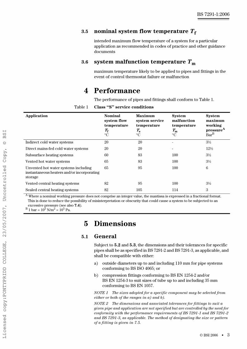
4 PerformanceThe performance of pipes and fittings shall conform to Table 1.
5 Dimensions
5.1 General
Subject to 5.2 and 5.3, the dimensions and their tolerances for specific pipes shall be as specified in BS 7291-2 and BS 7291-3, as applicable, and shall be compatible with either:
a) outside diameters up to and including 110 mm for pipe systems conforming to BS ISO 4065; or
b) compression fittings conforming to BS EN 1254-2 and/or BS EN 1254-3 to suit sizes of tube up to and including 35 mm conforming to BS EN 1057.
NOTE 1 The sizes adopted for a specific component may be selected from
either or both of the ranges in a) and b).
NOTE 2 The dimensions and associated tolerances for fittings to suit a
given pipe and application are not specified but are controlled by the need for
conformity with the performance requirements of BS 7291-1 and BS 7291-2
and BS 7291-3, as applicable. The method of designating the size or pattern
of a fitting is given in 7.5.
Table 1 Class “S” service conditions
Application Nominal
system flow
temperature
Tf
°C
Maximum
system service
temperature
Ts
°C
System
malfunction
temperature
Tm
°C
System
maximum
working
pressureA
BarB
Indirect cold water systems 20 20 - 3½
Direct mains-fed cold water systems 20 20 - 12½
Subsurface heating systems 60 83 100 3½
Vented hot water systems 65 83 100 3½
Unvented hot water systems including instantaneous heaters and/or incorporating storage
65 95 100 6
Vented central heating systems 82 95 100 3½
Sealed central heating systems 82 105 114 3A Where a nominal working pressure does not comprise an integer value, the mantissa is expressed in a fractional format.
This is done to reduce the possibility of misinterpretation or obscurity that could cause a system to be subjected to an excessive pressure (see also 7.4).
B 1 bar = 105 N/m2 = 105 Pa.
Licensed copy:PONTYPRIDD COLLEGE, 23/05/2007, Uncontrolled Copy, © BSI
www.bzfxw.com
BS 7291-1:2006
4 • © BSI 2006
5.2 Wall thickness of pipes
When determined in accordance with BS EN 2782-11:Method 1101A, the wall thickness of pipe shall be not less than one eleventh of the outside diameter, subject to a minimum value of 1.5 mm.
5.3 Coatings
If pipe is coated, the coating shall be sufficiently thin and/or removable to enable jointing with fittings and materials as specified in BS 7291-2:2006, 5.1, or BS 7291-3:2006, 5.1, as applicable.
NOTE Attention is drawn to 6.1; consideration should be given to the
possibility of diffusion of external coating constituents through the wall of the
pipe to its interior.
6 Performance
6.1 Effect of materials on the quality of drinking
water
When used under the conditions for which they are designated, non-metallic products in contact or likely to come into contact with drinking water shall conform to BS 6920-1.
NOTE There is no corresponding British Standard or associated test methods
generally applicable to metallic products which might come into contact with
drinking water. Attention is drawn to the Water Supply (Water Fittings)
Regulations [2] and to BS EN 1254-2 and/or BS EN 1254-3.
6.2 Long-term hydrostatic strength of pipes
6.2.1 Pipes shall either be:
a) tested in accordance with Annex A (see 6.2.2); or
b) tested in accordance with, and conform to, BS EN ISO 15875-2:2003, 4.2 (PE-X), or BS EN ISO 15876:2003, 4.2 (PB), as applicable.
6.2.2 When pipes are tested in accordance with Annex A:
a) there shall be no rupturing or cracking throughout the wall thick-ness of the test piece at any point, or leakage at any associated joint under test; and
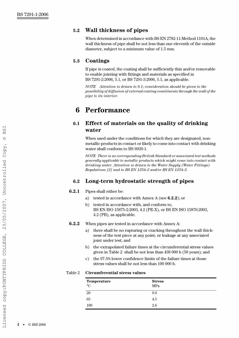
b) the extrapolated failure times at the circumferential stress values given in Table 2 shall be not less than 438 000 h (50 years); and
c) the 97.5% lower confidence limits of the failure times at those stress values shall be not less than 100 000 h.
Table 2 Circumferential stress values
Temperature
°CStress
MPa
20 9.0
65 4.5
100 2.6
Licensed copy:PONTYPRIDD COLLEGE, 23/05/2007, Uncontrolled Copy, © BSI
www.bzfxw.com
© BSI 2006 • 5
BS 7291-1:2006
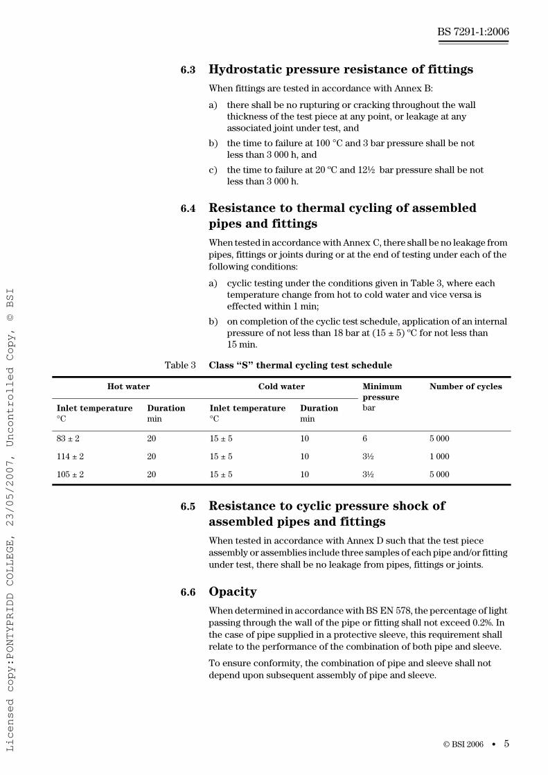
6.3 Hydrostatic pressure resistance of fittings
When fittings are tested in accordance with Annex B:
a) there shall be no rupturing or cracking throughout the wall thickness of the test piece at any point, or leakage at any associated joint under test, and
b) the time to failure at 100 °C and 3 bar pressure shall be not less than 3 000 h, and
c) the time to failure at 20 ºC and 12½ bar pressure shall be not less than 3 000 h.
6.4 Resistance to thermal cycling of assembled
pipes and fittings
When tested in accordance with Annex C, there shall be no leakage from pipes, fittings or joints during or at the end of testing under each of the following conditions:
a) cyclic testing under the conditions given in Table 3, where each temperature change from hot to cold water and vice versa is effected within 1 min;
b) on completion of the cyclic test schedule, application of an internal pressure of not less than 18 bar at (15 ± 5) ºC for not less than 15 min.
6.5 Resistance to cyclic pressure shock of
assembled pipes and fittings
When tested in accordance with Annex D such that the test piece assembly or assemblies include three samples of each pipe and/or fitting under test, there shall be no leakage from pipes, fittings or joints.
6.6 Opacity
When determined in accordance with BS EN 578, the percentage of light passing through the wall of the pipe or fitting shall not exceed 0.2%. In the case of pipe supplied in a protective sleeve, this requirement shall relate to the performance of the combination of both pipe and sleeve.
To ensure conformity, the combination of pipe and sleeve shall not depend upon subsequent assembly of pipe and sleeve.
Table 3 Class “S” thermal cycling test schedule
Hot water Cold water Minimum
pressure
bar
Number of cycles
Inlet temperature
°CDuration
minInlet temperature
°CDuration
min
83 ± 2 20 15 ± 5 10 6 5 000
114 ± 2 20 15 ± 5 10 3½ 1 000
105 ± 2 20 15 ± 5 10 3½ 5 000
Licensed copy:PONTYPRIDD COLLEGE, 23/05/2007, Uncontrolled Copy, © BSI
www.bzfxw.com
BS 7291-1:2006
6 • © BSI 2006
6.7 Oxygen permeability
When a barrier pipe is tested in accordance with Annex E, the oxygen permeability shall not exceed 0.1 g/(m3⋅d).
7 Marking and associated information
7.1 Each pipe shall be marked in accordance with BS 7291-2:2006, 6.1, or BS 7291-3:2006, 6.1, as applicable.
7.2 Each fitting shall be marked in accordance with BS 7291-2:2006, 6.2, or BS 7291-3:2006, 6.2.
7.3 The marking specified in BS 7291-2:2006, Clause 6, and BS 7291-3:2006, Clause 6, shall contrast clearly with the colour of the pipe, fitting or label, as applicable. It shall remain legible under handling, storage and installation conditions in accordance with BS 5955-8. Marking by indentation shall be to a depth not greater than 0.15 mm.
7.4 If additional markings include a pressure rating that does not comprise an integer value, the mantissa shall be presented as a fraction, e.g. 3½ (see Table 1).
7.5 The nominal size of a fitting or of each individual socket thereon shall be designated by the nominal size of the pipe(s) with which it is to be used. The method of designating the fitting shall be as follows, depending on the type of fitting.
a) Straight fittings and bends. For fittings having two unequal ends, the larger end shall be given first, e.g. 20 × 16.
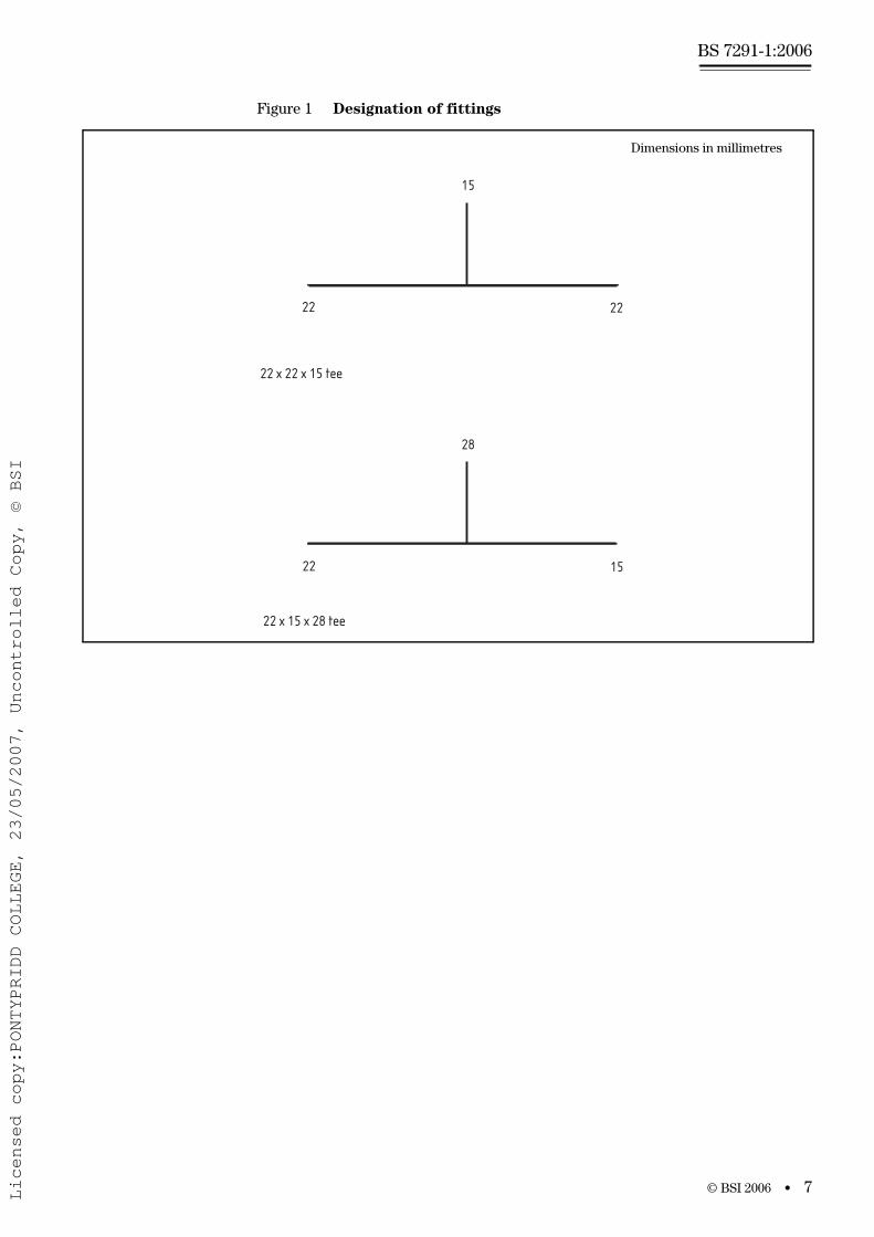
b) Tee fittings. Tee fittings shall be designated first by the ends on the run, i.e. two ends in the same straight line with, where applicable, the larger of the two being specified first, followed by the other end. (See Figure 1.)
c) Transition fittings. The end relating to BS 7291-1 shall be given first, followed by the other end.
EXAMPLES
22 mm × ¾ BS P thread external
10 mm × ½ BS P tail pipe end
22 mm × ¾ tank connector
15 mm × ½ tap connector
Licensed copy:PONTYPRIDD COLLEGE, 23/05/2007, Uncontrolled Copy, © BSI
www.bzfxw.com
© BSI 2006 • 7
BS 7291-1:2006
Figure 1 Designation of fittings
15
28
22 22
22 15
22 x 22 x 15 tee
22 x 15 x 28 tee
Dimensions in millimetres
Licensed copy:PONTYPRIDD COLLEGE, 23/05/2007, Uncontrolled Copy, © BSI
www.bzfxw.com
BS 7291-1:2006
8 • © BSI 2006
Annex A (normative) Test for minimum failure time
A.1 Principle
This method determines the minimum failure time of a thermoplastics material to be used for pipes or fittings class conforming to this standard. Test pieces are in the form of pipe or an assembly of pipe and fittings at the relevant temperatures, or interpolated, from testing, at temperatures above and below those quoted in Table 2. The test pieces are subjected to levels of sustained hydrostatic stress to produce failures of the pipe alone after periods according to Table A.1. The data are extrapolated to determine the failure times at the relevant stresses and temperatures, with reference to a lower 97.5% confidence limits for the results.
A.2 Apparatus and test temperature
The apparatus shall conform to BS EN 921, with water or air for the external test environment. The test temperatures shall be either those given in Table 2, in which case the failure time at the required stress shall be calculated by the method given in A.5, or other test temperatures, provided they are suitable for interpolation of the results in accordance with A.6.
A.3 Test pieces
Each test piece shall be a pipe manufactured from the thermoplastics material to be tested in barrier or non-barrier form. It shall have an outside diameter of 22 mm or the nearest to that diameter in a manufacturer’s range of products. The test piece shall be closed with pressure-tight caps or plugs such that the free length between end caps or plugs shall be not less than 150 mm.
A.4 Procedure
Obtain at least 18 test results at each test temperature for the calculation of the log of time versus log of stress regression line specified in A.5, with a failure data point distribution in accordance with Table A.1. Include as failures at the time of testing those test pieces that have not failed after being under test for more than 10 000 h if they increase the value of the extrapolated time (see A.5.4).
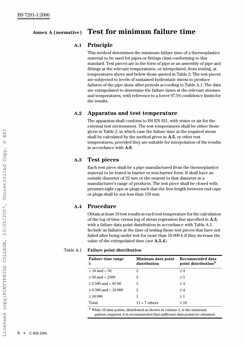
Table A.1 Failure point distribution
Failure time range
hMinimum data point
distribution
Recommended data
point distributionA
> 10 and < 50 2 ≥ 4≥ 50 and < 2500 3 ≥ 5≥ 2 500 and < 65 00 3 ≥ 4≥ 6 500 and < 10 000 2 ≥ 4≥ 10 000 1 ≥ 1Total 11 + 7 others ≥ 18
A While 18 data points, distributed as shown in column 2, is the minimum pattern required, it is recommended that sufficient data points be obtained.
Licensed copy:PONTYPRIDD COLLEGE, 23/05/2007, Uncontrolled Copy, © BSI
www.bzfxw.com
© BSI 2006 • 9
BS 7291-1:2006
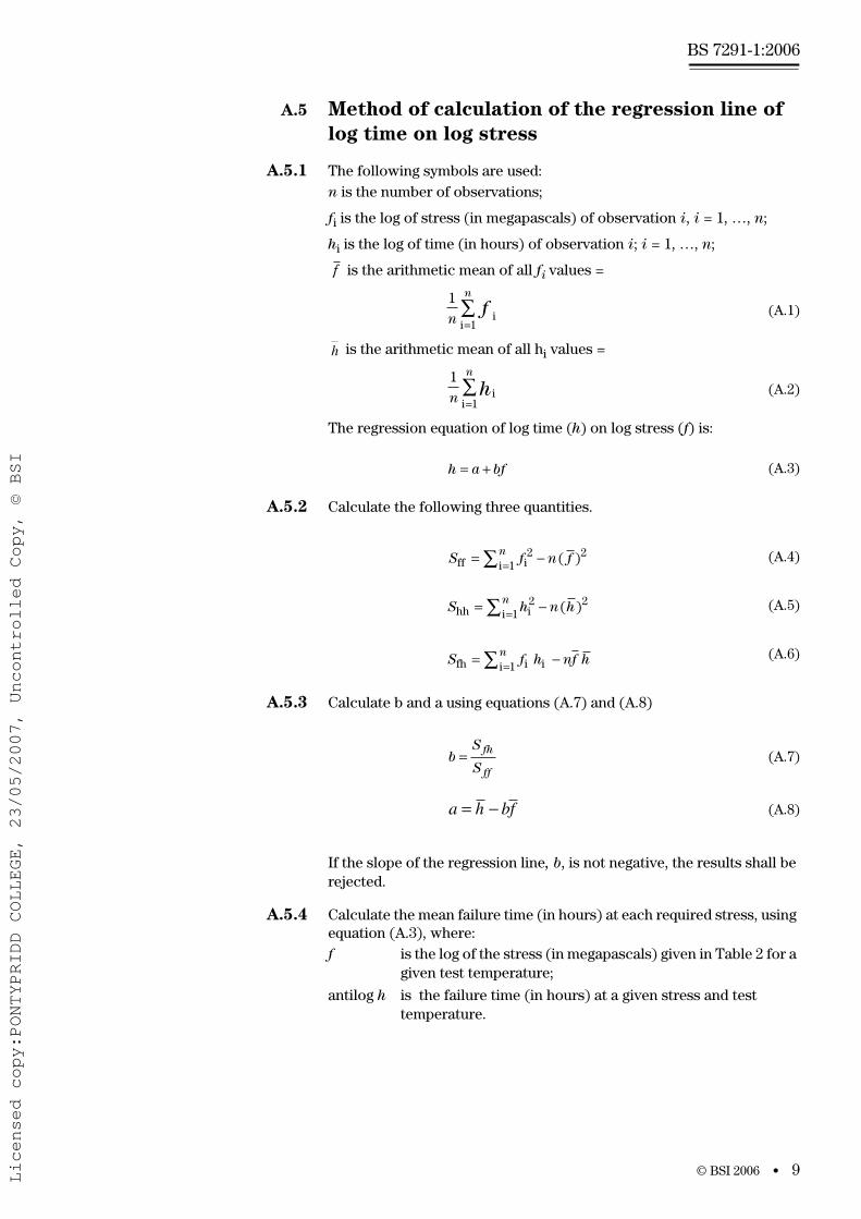
A.5 Method of calculation of the regression line of
log time on log stress
A.5.1 The following symbols are used:n is the number of observations;
fi is the log of stress (in megapascals) of observation i, i = 1, …, n;
hi is the log of time (in hours) of observation i; i = 1, …, n;
is the arithmetic mean of all fi values =
(A.1)
is the arithmetic mean of all hi values =
(A.2)
The regression equation of log time (h) on log stress (f) is:
(A.3)
A.5.2 Calculate the following three quantities.
(A.4)
(A.5)
(A.6)
A.5.3 Calculate b and a using equations (A.7) and (A.8)
(A.7)
(A.8)
If the slope of the regression line, b, is not negative, the results shall be rejected.
A.5.4 Calculate the mean failure time (in hours) at each required stress, using equation (A.3), where: f is the log of the stress (in megapascals) given in Table 2 for a
given test temperature;
antilog h is the failure time (in hours) at a given stress and test temperature.
f
1
1nf
n
ii=∑
h
1
1nh
n
ii=∑
h a bf= +
S f n fn
ff ii= −=∑ 2
12( )
S h n hn
hh ii= −=∑ 2
12( )
S f h nf hn
fh i ii= −=∑ 1
bS
S
fh
ff
=
a h bf= −
Licensed copy:PONTYPRIDD COLLEGE, 23/05/2007, Uncontrolled Copy, © BSI
www.bzfxw.com
BS 7291-1:2006
10 • © BSI 2006
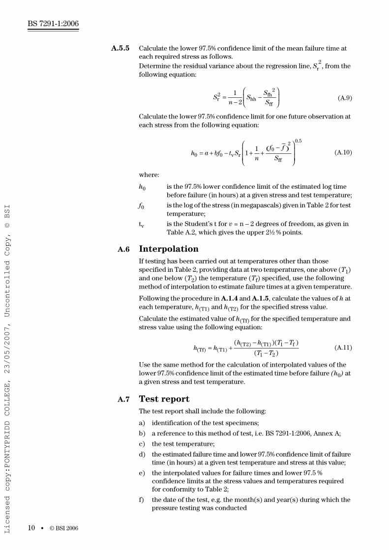
A.5.5 Calculate the lower 97.5% confidence limit of the mean failure time at each required stress as follows.Determine the residual variance about the regression line, Sr
2, from the
following equation:
(A.9)
Calculate the lower 97.5% confidence limit for one future observation at each stress from the following equation:
(A.10)
where:
h0 is the 97.5% lower confidence limit of the estimated log time before failure (in hours) at a given stress and test temperature;
f0 is the log of the stress (in megapascals) given in Table 2 for test temperature;
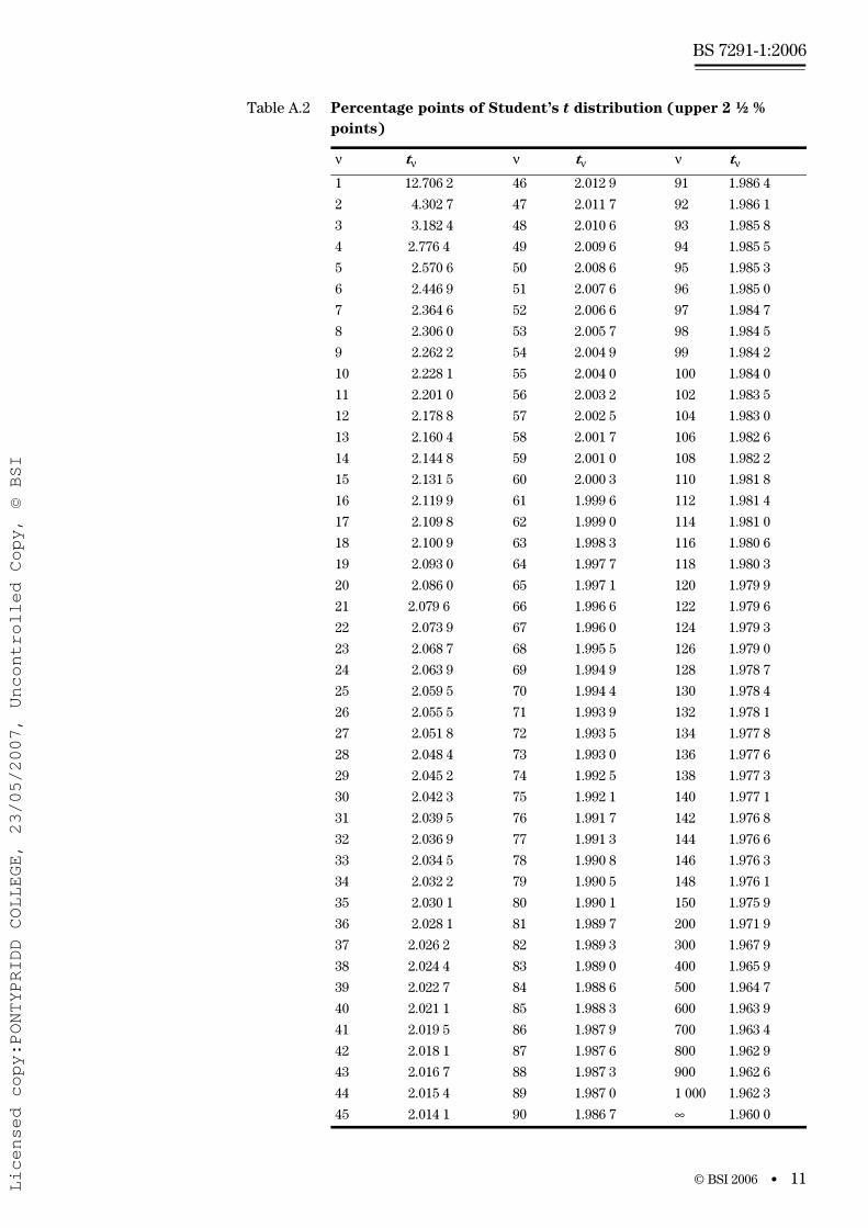
tv is the Student’s t for v = n – 2 degrees of freedom, as given in Table A.2, which gives the upper 2½ % points.
A.6 Interpolation
If testing has been carried out at temperatures other than those specified in Table 2, providing data at two temperatures, one above (T1) and one below (T2) the temperature (Tf) specified, use the following method of interpolation to estimate failure times at a given temperature.
Following the procedure in A.1.4 and A.1.5, calculate the values of h at each temperature, h(T1) and h(T2) for the specified stress value.
Calculate the estimated value of h(Tf) for the specified temperature and stress value using the following equation:
(A.11)
Use the same method for the calculation of interpolated values of the lower 97.5% confidence limit of the estimated time before failure (h0) at a given stress and test temperature.
A.7 Test report
The test report shall include the following:
a) identification of the test specimens;
b) a reference to this method of test, i.e. BS 7291-1:2006, Annex A;
c) the test temperature;
d) the estimated failure time and lower 97.5% confidence limit of failure time (in hours) at a given test temperature and stress at this value;
e) the interpolated values for failure times and lower 97.5 % confidence limits at the stress values and temperatures required for conformity to Table 2;
f) the date of the test, e.g. the month(s) and year(s) during which the pressure testing was conducted
Sn
SS
Sr2
hhfh
ff=
−−
⎛
⎝⎜
⎞
⎠⎟
1
2
2
h a bf t Sn
f f
S0
02 0 5
11
= + − + +−( )⎛
⎝⎜⎜
⎞
⎠⎟⎟0 v r
ff
.
h hh h T T
T T(Tf) T1
T T f= +− −
−( )( ) ( )( )( )
( )2 1 1
1 2
Licensed copy:PONTYPRIDD COLLEGE, 23/05/2007, Uncontrolled Copy, © BSI
www.bzfxw.com
© BSI 2006 • 11
BS 7291-1:2006
Table A.2 Percentage points of Student’s t distribution (upper 2 ½ %
points)
ν tν ν tν ν tν
1 12.706 2 46 2.012 9 91 1.986 4
2 4.302 7 47 2.011 7 92 1.986 1
3 3.182 4 48 2.010 6 93 1.985 8
4 2.776 4 49 2.009 6 94 1.985 5
5 2.570 6 50 2.008 6 95 1.985 3
6 2.446 9 51 2.007 6 96 1.985 0
7 2.364 6 52 2.006 6 97 1.984 7
8 2.306 0 53 2.005 7 98 1.984 5
9 2.262 2 54 2.004 9 99 1.984 2
10 2.228 1 55 2.004 0 100 1.984 0
11 2.201 0 56 2.003 2 102 1.983 5
12 2.178 8 57 2.002 5 104 1.983 0
13 2.160 4 58 2.001 7 106 1.982 6
14 2.144 8 59 2.001 0 108 1.982 2
15 2.131 5 60 2.000 3 110 1.981 8
16 2.119 9 61 1.999 6 112 1.981 4
17 2.109 8 62 1.999 0 114 1.981 0
18 2.100 9 63 1.998 3 116 1.980 6
19 2.093 0 64 1.997 7 118 1.980 3
20 2.086 0 65 1.997 1 120 1.979 9
21 2.079 6 66 1.996 6 122 1.979 6
22 2.073 9 67 1.996 0 124 1.979 3
23 2.068 7 68 1.995 5 126 1.979 0
24 2.063 9 69 1.994 9 128 1.978 7
25 2.059 5 70 1.994 4 130 1.978 4
26 2.055 5 71 1.993 9 132 1.978 1
27 2.051 8 72 1.993 5 134 1.977 8
28 2.048 4 73 1.993 0 136 1.977 6
29 2.045 2 74 1.992 5 138 1.977 3
30 2.042 3 75 1.992 1 140 1.977 1
31 2.039 5 76 1.991 7 142 1.976 8
32 2.036 9 77 1.991 3 144 1.976 6
33 2.034 5 78 1.990 8 146 1.976 3
34 2.032 2 79 1.990 5 148 1.976 1
35 2.030 1 80 1.990 1 150 1.975 9
36 2.028 1 81 1.989 7 200 1.971 9
37 2.026 2 82 1.989 3 300 1.967 9
38 2.024 4 83 1.989 0 400 1.965 9
39 2.022 7 84 1.988 6 500 1.964 7
40 2.021 1 85 1.988 3 600 1.963 9
41 2.019 5 86 1.987 9 700 1.963 4
42 2.018 1 87 1.987 6 800 1.962 9
43 2.016 7 88 1.987 3 900 1.962 6
44 2.015 4 89 1.987 0 1 000 1.962 3
45 2.014 1 90 1.986 7 ∞ 1.960 0
Licensed copy:PONTYPRIDD COLLEGE, 23/05/2007, Uncontrolled Copy, © BSI
www.bzfxw.com
BS 7291-1:2006
12 • © BSI 2006
Annex B (normative) Method of test for hydrostatic pressure resistance of fittings
B.1 Principle
An assembly incorporating one or more fittings jointed with pipe is subjected to a sustained pressure at a specified temperature, and inspected for rupture or leakage before a specified period of time has elapsed.
B.2 Apparatus
The apparatus shall conform to BS EN 921 with water or air as the external test environment, together with ancillary supports as necessary to accommodate a test assembly conforming to B.3.
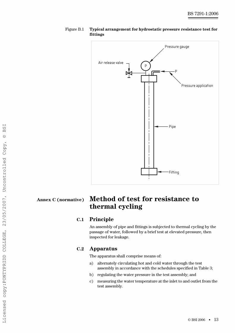
B.3 Test assembly
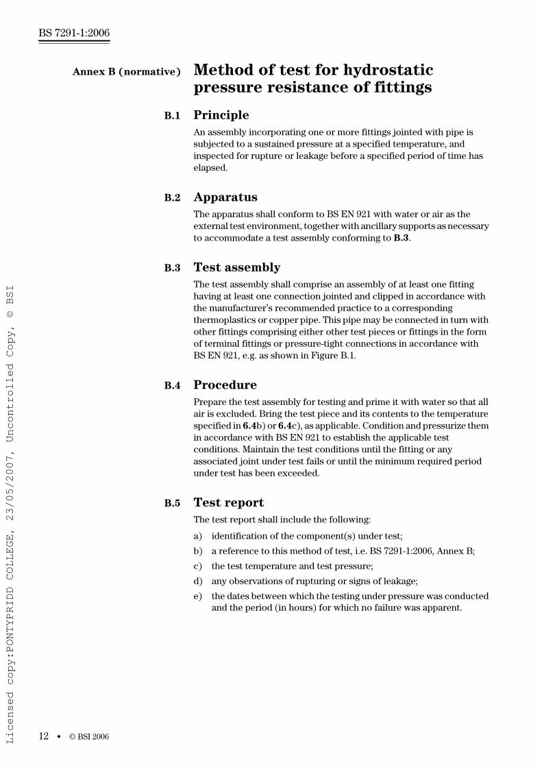
The test assembly shall comprise an assembly of at least one fitting having at least one connection jointed and clipped in accordance with the manufacturer’s recommended practice to a corresponding thermoplastics or copper pipe. This pipe may be connected in turn with other fittings comprising either other test pieces or fittings in the form of terminal fittings or pressure-tight connections in accordance with BS EN 921, e.g. as shown in Figure B.1.
B.4 Procedure
Prepare the test assembly for testing and prime it with water so that all air is excluded. Bring the test piece and its contents to the temperature specified in 6.4b) or 6.4c), as applicable. Condition and pressurize them in accordance with BS EN 921 to establish the applicable test conditions. Maintain the test conditions until the fitting or any associated joint under test fails or until the minimum required period under test has been exceeded.
B.5 Test report
The test report shall include the following:
a) identification of the component(s) under test;
b) a reference to this method of test, i.e. BS 7291-1:2006, Annex B;
c) the test temperature and test pressure;
d) any observations of rupturing or signs of leakage;
e) the dates between which the testing under pressure was conducted and the period (in hours) for which no failure was apparent.
Licensed copy:PONTYPRIDD COLLEGE, 23/05/2007, Uncontrolled Copy, © BSI
www.bzfxw.com
© BSI 2006 • 13
BS 7291-1:2006
Figure B.1 Typical arrangement for hydrostatic pressure resistance test for
fittings
Annex C (normative) Method of test for resistance to thermal cycling
C.1 Principle
An assembly of pipe and fittings is subjected to thermal cycling by the passage of water, followed by a brief test at elevated pressure, then inspected for leakage.
C.2 Apparatus
The apparatus shall comprise means of:
a) alternately circulating hot and cold water through the test assembly in accordance with the schedules specified in Table 3;
b) regulating the water pressure in the test assembly; and
c) measuring the water temperature at the inlet to and outlet from the test assembly.
PP
Pressure gauge
Pressure application
Pipe
Fitting
Air release valve
Licensed copy:PONTYPRIDD COLLEGE, 23/05/2007, Uncontrolled Copy, © BSI
www.bzfxw.com
BS 7291-1:2006
14 • © BSI 2006
The alternation equipment shall be capable of effecting each change between hot and cold water sources within a specified period.
For testing of flexible pipe, devices shall be included to apply a sustained tension to lengths of straight pipe.
C.3 Test assembly
C.3.1 General
The test assembly shall comprise pipe and fittings jointed and clipped in accordance with the manufacturer’s instructions.
Where a range of fittings is available, the assembly shall comprise a representative selection of sizes and configurations manufactured or recommended by the manufacturer, arranged so that the sizes under test increase sequentially in the direction of flow, e.g. as shown in Figure C.1.
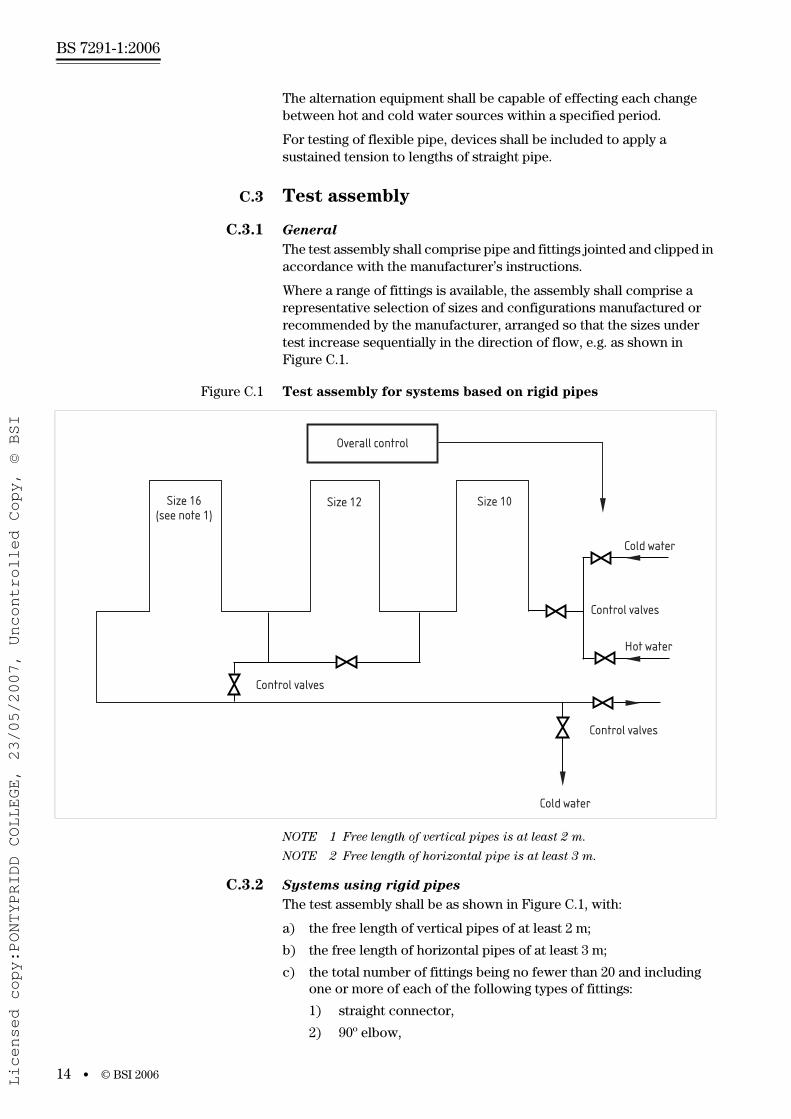
Figure C.1 Test assembly for systems based on rigid pipes
NOTE 1 Free length of vertical pipes is at least 2 m.
NOTE 2 Free length of horizontal pipe is at least 3 m.
C.3.2 Systems using rigid pipes
The test assembly shall be as shown in Figure C.1, with:
a) the free length of vertical pipes of at least 2 m;
b) the free length of horizontal pipes of at least 3 m;
c) the total number of fittings being no fewer than 20 and including one or more of each of the following types of fittings:
1) straight connector,
2) 90º elbow,
Overall control
Size 16(see note 1)
Size 12 Size 10
Control valves
Cold water
Control valves
Hot water
Control valves
Cold water
Licensed copy:PONTYPRIDD COLLEGE, 23/05/2007, Uncontrolled Copy, © BSI
www.bzfxw.com
© BSI 2006 • 15
BS 7291-1:2006
3) 90º tee,
4) plastics to metal transition fitting.
If a manufacturer recommends a particular installation practice, for example an expansion loop, bend clip or cold bend, it shall be included in the test.
C.3.3 Systems using flexible pipes
The test assembly shall include:
a) at least one pair of pre-stressed pipes linked by a straight connector, incorporated in accordance with Figure C.2 (see branch A) and stressed as shown in C.4, with the free length of each such combination being 3 m ± 25 mm;
b) at least two straight pipes, each free to move when incorporated as shown in Figure C.2 (see branch B) and each having a free length of (300 ± 5) mm;
c) at least one bent pipe, as shown in Figure C.3, with each pipe supported only by its ends when incorporated in accordance with Figure C.2 such that the free length of the pipe lies in the range 27de to 28de, inclusive, where de is the nominal outside diameter of the pipe.
C.4 Procedure
Prepare the test assembly for testing and prime it with water so that all air is excluded.
In the case of flexible piping, pre-stress the test pieces (see C.3.3 and Figure C.2) to an initial tensile stress equivalent to that induced by contraction when subjected to a temperature drop of 20 ºC.
Subject the test assembly to the passage of the specified cycles of hot and cold water at the pressures, temperatures and durations specified in Table 3. Perform any desired tightening or adjustment of joints within the first five cycles. Control the flow rate of the circulating water such that the measured temperature drop on the hot cycle from the inlet to the outlet of the test assembly does not exceed 5 ºC.
On completion of the cyclic test schedule, subject the assembly to the applicable test at elevated pressure [see 6.5b)] and inspect all joints for signs of leakage.
NOTE To minimize temperature differences, balancing valves or series
connections might be necessary in parts of the circuit.
C.5 Test report
The test report shall include the following:
a) identification of the components under test;
b) a reference to this method of test; i.e. BS 7291-1:2006; Annex C;
c) the test conditions, as indicated by Class “S”;
d) any observations of signs of leakage;
e) the period of the test, e.g. the dates between which the thermal cycling test schedule was conducted.
Licensed copy:PONTYPRIDD COLLEGE, 23/05/2007, Uncontrolled Copy, © BSI
www.bzfxw.com
BS 7291-1:2006
16 • © BSI 2006
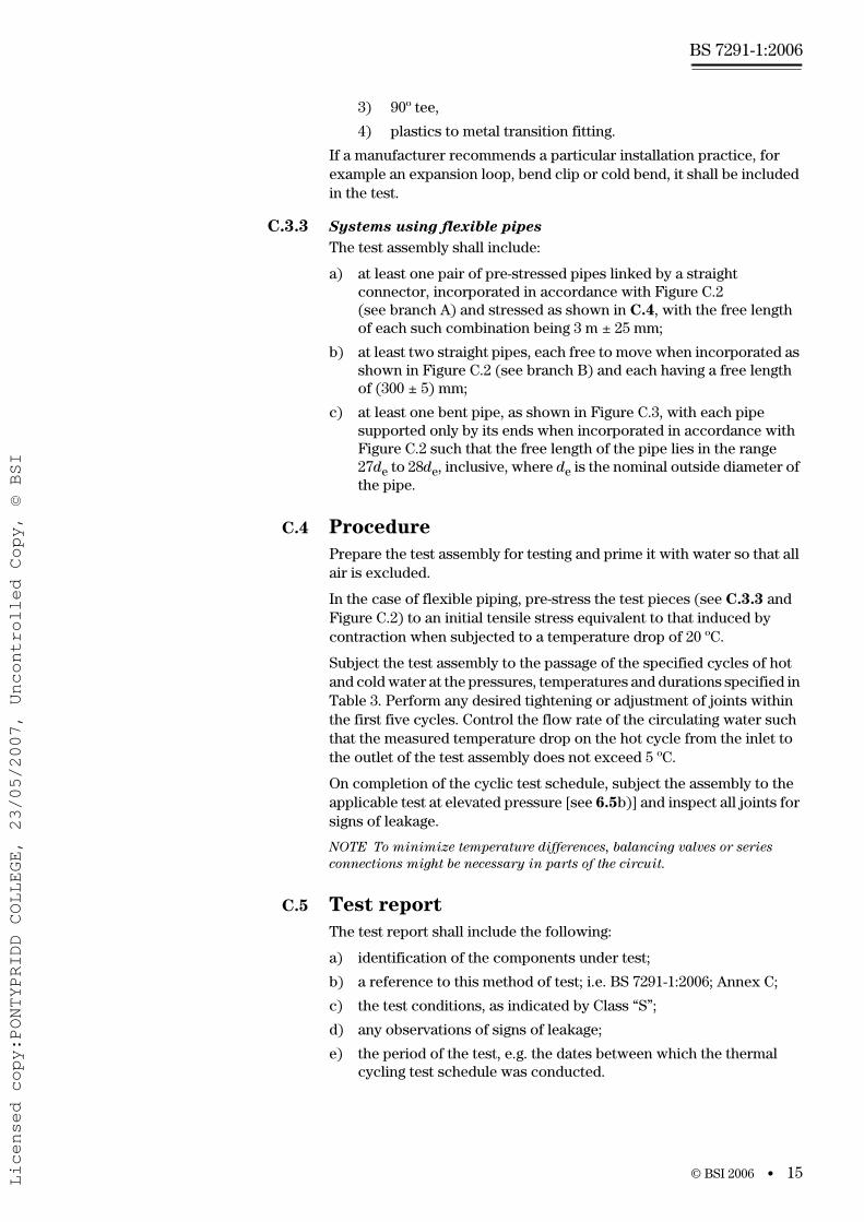
Figure C.2 Test assembly for systems based on flexible pipes
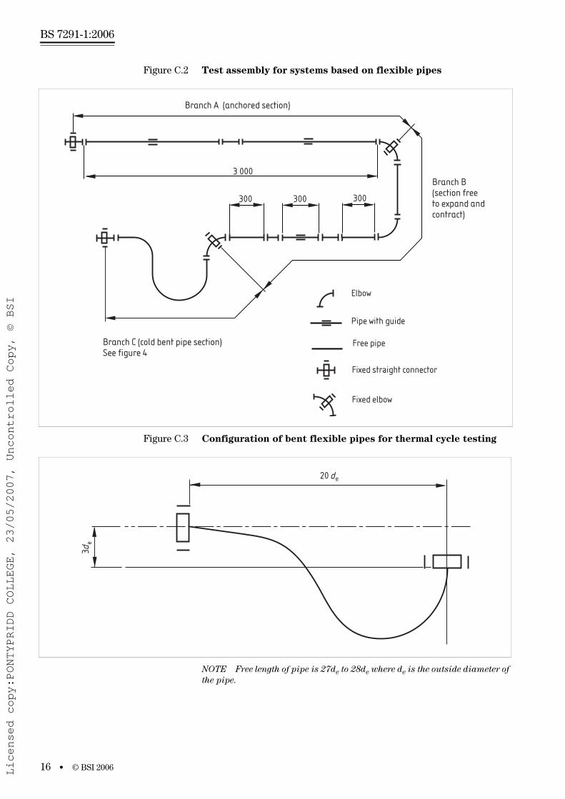
Figure C.3 Configuration of bent flexible pipes for thermal cycle testing
NOTE Free length of pipe is 27de to 28de where de is the outside diameter of
the pipe.
Branch A (anchored section)
3 000
300 300300
Branch C (cold bent pipe section)See figure 4
Branch B(section freeto expand and contract)
Elbow
Pipe with guide
Free pipe
Fixed straight connector
Fixed elbow
3de
20 de
Licensed copy:PONTYPRIDD COLLEGE, 23/05/2007, Uncontrolled Copy, © BSI
www.bzfxw.com
© BSI 2006 • 17
BS 7291-1:2006
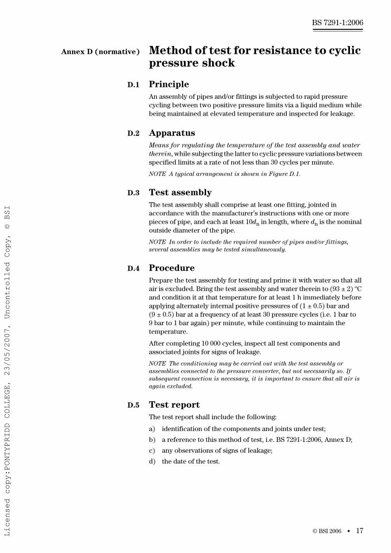
Annex D (normative) Method of test for resistance to cyclic pressure shock
D.1 Principle
An assembly of pipes and/or fittings is subjected to rapid pressure cycling between two positive pressure limits via a liquid medium while being maintained at elevated temperature and inspected for leakage.
D.2 Apparatus
Means for regulating the temperature of the test assembly and water
therein, while subjecting the latter to cyclic pressure variations between specified limits at a rate of not less than 30 cycles per minute.
NOTE A typical arrangement is shown in Figure D.1.
D.3 Test assembly
The test assembly shall comprise at least one fitting, jointed in accordance with the manufacturer’s instructions with one or more pieces of pipe, and each at least 10dn in length, where dn is the nominal outside diameter of the pipe.
NOTE In order to include the required number of pipes and/or fittings,
several assemblies may be tested simultaneously.
D.4 Procedure
Prepare the test assembly for testing and prime it with water so that all air is excluded. Bring the test assembly and water therein to (93 ± 2) ºC and condition it at that temperature for at least 1 h immediately before applying alternately internal positive pressures of (1 ± 0.5) bar and (9 ± 0.5) bar at a frequency of at least 30 pressure cycles (i.e. 1 bar to 9 bar to 1 bar again) per minute, while continuing to maintain the temperature.
After completing 10 000 cycles, inspect all test components and associated joints for signs of leakage.
NOTE The conditioning may be carried out with the test assembly or
assemblies connected to the pressure converter, but not necessarily so. If
subsequent connection is necessary, it is important to ensure that all air is
again excluded.
D.5 Test report
The test report shall include the following:
a) identification of the components and joints under test;
b) a reference to this method of test, i.e. BS 7291-1:2006, Annex D;
c) any observations of signs of leakage;
d) the date of the test.
Licensed copy:PONTYPRIDD COLLEGE, 23/05/2007, Uncontrolled Copy, © BSI
www.bzfxw.com
BS 7291-1:2006
18 • © BSI 2006
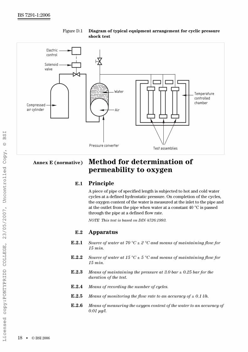
Figure D.1 Diagram of typical equipment arrangement for cyclic pressure
shock test
Annex E (normative) Method for determination of permeability to oxygen
E.1 Principle
A piece of pipe of specified length is subjected to hot and cold water cycles at a defined hydrostatic pressure. On completion of the cycles, the oxygen content of the water is measured at the inlet to the pipe and at the outlet from the pipe when water at a constant 40 °C is passed through the pipe at a defined flow rate.
NOTE This test is based on DIN 4726:1993.
E.2 Apparatus
E.2.1 Source of water at 70 °C ± 2 °C and means of maintaining flow for
15 min.
E.2.2 Source of water at 15 °C ± 5 °C and means of maintaining flow for
15 min.
E.2.3 Means of maintaining the pressure at 3.0 bar ± 0.25 bar for the
duration of the test.
E.2.4 Means of recording the number of cycles.
E.2.5 Means of monitoring the flow rate to an accuracy of ± 0.1 l/h.
E.2.6 Means of measuring the oxygen content of the water to an accuracy of
0.01 µg/l.
Electriccontrol
Solenoidvalve
Compressedair cylinder
Test assemblies
Temperaturecontrolledchamber
Air
Water
Pressure converter
Licensed copy:PONTYPRIDD COLLEGE, 23/05/2007, Uncontrolled Copy, © BSI
www.bzfxw.com
© BSI 2006 • 19
BS 7291-1:2006
E.2.7 Thermometer with an accuracy of ± 0.5 °C, for measuring and recording the temperature at the inlet and outlet of the test piece.
E.2.8 Device for measuring and recording the pressure in the test piece.
E.2.9 Barometer with an accuracy of ± 0.001 bar, for measuring atmospheric pressure.
E.2.10 Mandrel, with a diameter nine times that of the test specimen.
E.3 Test piece
The test piece is a section of pipe 20 m in length joined, if necessary, using straight connectors or elbows.
E.4 Procedure
Condition the test specimen at ambient temperature for at least 24 h prior to installation in the apparatus.
Prepare the test specimen for securing in the test rig. Wrap at least 2 m of the test specimen around the mandrel and secure in position.
Install the test specimen in the apparatus, fill with water and bleed off the air. Condition the assembly at a temperature of 20 °C ± 5 °C at atmospheric pressure for a period of 24 h.
Pressurize the system to 3.0 bar ± 0.25 bar and start the temperature cycling. The change-over between each phase shall occur within 60 s as measured at the entry to the test piece. Short-term deviations of – 0.5 bar are acceptable during the change-over phase. After 28 days and the completion of 1 344 cycles, release the pressure and allow the assembly to stabilize at ambient temperature for 24 h.
Pass water at 40 °C ± 1 °C through the test specimen at a flow rate that creates a temperature drop of from 2 °C to 4 °C between the measured inlet and outlet temperature.
Carry out two sets of tests, one at 1.0 bar and one at 3.0 bar, in excess of atmospheric pressure.
Allow the system to stabilize for at least 1 h, then take three separate readings each of:
a) flow rate;
b) temperature at inlet;
c) temperature at outlet;
d) oxygen content of the water at the inlet and outlet of the test piece; and
e) the atmospheric pressure.
E.5 Calculations
Calculate the oxygen diffusion rate or the difference between the inlet and outlet oxygen content (g/(m3
• day)) from:
II
(d tvol
4)
=−2 2π
Licensed copy:PONTYPRIDD COLLEGE, 23/05/2007, Uncontrolled Copy, © BSI
www.bzfxw.com
BS 7291-1:2006
20 • © BSI 2006
where:
I =
d = pipe diameter (m)
t = pipe wall thickness (m)
∆c = change in oxygen content (µg/l)
V = flow rate (l/h)
p0 = atmospheric pressure
p = measured atmospheric pressure.
E.6 Test report
The test report shall include the following:
a) reference to this test method, i.e. BS 7291-1:2006, Annex E;
b) complete identification of the test specimen;
c) nominal diameter and thickness of the pipe;
d) measured diameter and thickness of the pipe;
e) the oxygen diffusion rate;
f) observations made during, or after, the test that might have affected the result; and
g) the dates of the start and finish of the test.
Annex F (informative) Guidance on factory control procedures
The following guidance on the nature of the requirements and test methods specified in this part of BS 7291 is provided to assist in the preparation of quality plans for the manufacture of pipes or fittings conforming to this and other parts of BS 7291.
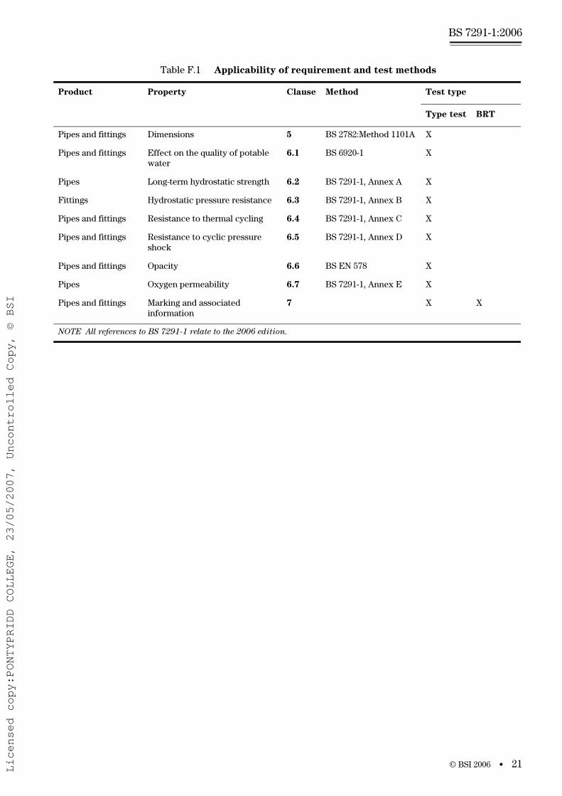
The applicability of specific requirements and associated methods of test to different types of pipe or fitting is summarized in Table F.1, in which each requirement is classified as being considered particularly suitable for type test and/or batch release tests (BRT) purposes.
Type tests are intended to prove the suitability and performance of a material composition, a compounding or processing technique or a design or size of pipe, fitting or joint assembly. Such tests should be performed when any introduction or change is made in one or more of those aspects, but they may be performed more frequently by incorporation into a plan for monitoring the consistency of manufacture.
BRTs are carried out during and/or following manufacture to monitor the quality of a product item, as applicable. Certain test methods and associated requirements have been included because of the practicality and speed with which they can be performed in conjunction with a production process, compared with some of the type tests.
Some of the requirements in this standard are relevant to both type test and BRT purposes, e.g. those for dimensions.
24 10 3 0× − ∆cVp
p
Licensed copy:PONTYPRIDD COLLEGE, 23/05/2007, Uncontrolled Copy, © BSI
www.bzfxw.com
© BSI 2006 • 21
BS 7291-1:2006
Table F.1 Applicability of requirement and test methods
Product Property Clause Method Test type
Type test BRT
Pipes and fittings Dimensions 5 BS 2782:Method 1101A X
Pipes and fittings Effect on the quality of potable water
6.1 BS 6920-1 X
Pipes Long-term hydrostatic strength 6.2 BS 7291-1, Annex A X
Fittings Hydrostatic pressure resistance 6.3 BS 7291-1, Annex B X
Pipes and fittings Resistance to thermal cycling 6.4 BS 7291-1, Annex C X
Pipes and fittings Resistance to cyclic pressure shock
6.5 BS 7291-1, Annex D X
Pipes and fittings Opacity 6.6 BS EN 578 X
Pipes Oxygen permeability 6.7 BS 7291-1, Annex E X
Pipes and fittings Marking and associated information
7 X X
NOTE All references to BS 7291-1 relate to the 2006 edition.
Licensed copy:PONTYPRIDD COLLEGE, 23/05/2007, Uncontrolled Copy, © BSI
www.bzfxw.com
BS 7291-1:2006
22 • © BSI 2006
Bibliography
Standards
BS 6100-2.7, Glossary of building and civil engineering terms —
Section 2.7: Public Health — Environmental Engineering.
BS 6100-3.3, Glossary of building and civil engineering terms —
Section 3.3: Sanitation.
BS 2782-11:Method 1101A, Methods of testing plastics — Part 11:
Method 1101A, Thermoplastics pipes, fitting and valves —
Measurement of dimensions of pipes.
BS 1755-1, Glossary of terms used in the plastics industry — Part 1:
Polymer and plastics technology.
BS EN 1982:1999, Copper and copper alloys — Ingots and castings.
BS EN ISO/IEC 17025, General requirements for the competence of
testing and calibration laboratories.
DIN 4726:1993, Pipelines of plastic materials used in warm water floor
heating systems — General requirements.
Other publications
[1] GREAT BRITAIN: The Health and Safety at Work, etc Act 1974, The Stationery Office: London.
[2] GREAT BRITAIN: The Water Supply (Water Fittings) Regulations 1999, SI 1999, No. 1148, The Stationery Office: London.
Licensed copy:PONTYPRIDD COLLEGE, 23/05/2007, Uncontrolled Copy, © BSI

www.bzfxw.com
This page deliberately left blank
BS 7291-1:2006
Licensed copy:PONTYPRIDD COLLEGE, 23/05/2007, Uncontrolled Copy, © BSI
www.bzfxw.com
BSI – British Standards Institution
BSI is the independent national body responsible for preparing British Standards. It presents the UK view on standards in Europe and at the international level. It is incorporated by Royal Charter.
Revisions
British Standards are updated by amendment or revision. Users of British Standards should make sure that they possess the latest amendments or editions.
It is the constant aim of BSI to improve the quality of our products and services. We would be grateful if anyone finding an inaccuracy or ambiguity while using this British Standard would inform the Secretary of the technical committee responsible, the identity of which can be found on the inside front cover. Tel: +44 (0)20 8996 9000. Fax: +44 (0)20 8996 7400.
BSI offers members an individual updating service called PLUS which ensures that subscribers automatically receive the latest editions of standards.
Buying standards
Orders for all BSI, international and foreign standards publications should be addressed to Customer Services. Tel: +44 (0)20 8996 9001. Fax: +44 (0)20 8996 7001. Email: [email protected]. Standards are also available from the BSI website at http://www.bsi-global.com.
In response to orders for international standards, it is BSI policy to supply the BSI implementation of those that have been published as British Standards, unless otherwise requested.
Information on standards
BSI provides a wide range of information on national, European and international standards through its Library and its Technical Help to Exporters Service. Various BSI electronic information services are also available which give details on all its products and services. Contact the Information Centre. Tel: +44 (0)20 8996 7111. Fax: +44 (0)20 8996 7048. Email: [email protected].
Subscribing members of BSI are kept up to date with standards developments and receive substantial discounts on the purchase price of standards. For details of these and other benefits contact Membership Administration. Tel: +44 (0)20 8996 7002. Fax: +44 (0)20 8996 7001. Email: [email protected].
Information regarding online access to British Standards via British Standards Online can be found at http://www.bsi-global.com/bsonline.
Further information about BSI is available on the BSI website at http://www.bsi-global.com.
Copyright
Copyright subsists in all BSI publications. BSI also holds the copyright, in the UK, of the publications of the international standardization bodies. Except as permitted under the Copyright, Designs and Patents Act 1988 no extract may be reproduced, stored in a retrieval system or transmitted in any form or by any means – electronic, photocopying, recording or otherwise – without prior written permission from BSI.
This does not preclude the free use, in the course of implementing the standard, of necessary details such as symbols, and size, type or grade designations. If these details are to be used for any other purpose than implementation then the prior written permission of BSI must be obtained.
Details and advice can be obtained from the Copyright & Licensing Manager.Tel: +44 (0)20 8996 7070. Fax: +44 (0)20 8996 7553.Email: [email protected].
BS 7291-1:2006
389 Chiswick High RoadLondonW4 4AL
Licensed copy:PONTYPRIDD COLLEGE, 23/05/2007, Uncontrolled Copy, © BSI