Embed Size (px)
Citation preview
PageORIENTAL MOTOR GENERAL CATALOG 2012/2013
D-60 Features D-60 / System Configuration D-62 / Product Line D-63 / Specifications D-64 / Characteristics D-65Dimensions D-70 / Connection and Operation D-77 / Motor and Driver Combinations D-83
Brushless Motors
BLF Series●Additional Information●
Technical reference ➜ Page G-1
Safety standards ➜ Page H-2
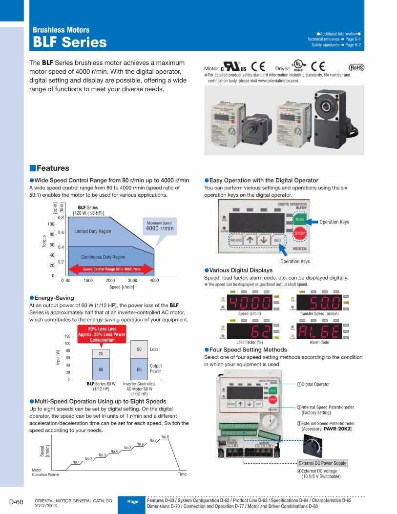
The BLF Series brushless motor achieves a maximum
motor speed of 4000 r/min. With the digital operator,
digital setting and display are possible, offering a wide
range of functions to meet your diverse needs.
Motor: Driver: For detailed product safety standard information including standards, file number and ●certification body, please visit www.orientalmotor.com.
Features ■
Wide Speed Control Range from 80 r/min up to 4000 r/min ●A wide speed control range from 80 to 4000 r/min (speed ratio of
50:1) enables the motor to be used for various applications.
0 3000100080 4000
Speed [r/min]
[N·m
]
0.6
0.4
0.2
0.8
2000
Limited Duty Region
BLF Series
[120 W (1/6 HP)]
Continuous Duty Region
Maximum Speed
4000 r/min
Speed Control Range 80 to 4000 r/min
0
20
40
60
80
100
[oz-
in]
Torq
ue
Energy-Saving ●At an output power of 60 W (1/12 HP), the power loss of the BLFSeries is approximately half that of an inverter-controlled AC motor,
which contributes to the energy-saving operation of your equipment.
Inp
ut
[W]
Output
Power
Loss
0
40
20
60
80
100
120
25
60
50
60
Inverter-Controlled
AC Motor 60 W
(1/12 HP)
BLF Series 60 W
(1/12 HP)
50% Less Loss
Approx. 23% Less Power
Consumption
Multi-Speed Operation Using up to Eight Speeds ●Up to eight speeds can be set by digital setting. On the digital
operator, the speed can be set in units of 1 r/min and a different
acceleration/deceleration time can be set for each speed. Switch the
speed according to your needs.
No.1
Motor
Operation Pattern
No.2No.3
No.4No.5
No.6No.7
No.8
Time
Spee
d
[r/m
in]
Easy Operation with the Digital Operator ●You can perform various settings and operations using the six
operation keys on the digital operator.
Operation Keys
Operation Keys
Various Digital Displays ●Speed, load factor, alarm code, etc. can be displayed digitally.
The speed can be displayed as gearhead output shaft speed. ●
Speed (r/min)
Load Factor (%)
Transfer Speed (m/min)
Alarm Code
Four Speed Setting Methods ●Select one of four speed setting methods according to the condition
in which your equipment is used.
①Digital Operator
②Internal Speed Potentiometer (Factory setting)
③External Speed Potentiometer (Accessory: PAVR-20KZ)
④External DC Voltage (10 V/5 V Switchable)
External DC Power Supply

D-61
Brushless Motors/AC Speed Control MotorsIn
trod
uctio
n
Bru
shless M
oto
rsA
C S
peed
Co
ntro
l Mo
tors
Accesso
riesIn
stallation
AC
Inp
ut
DC
Inp
ut
BH
FFE1
00/
FE200
ES01/
ES02
US
BX
BLF
BLE
BLU
BLH
BLV
CAD DataManuals
www.orientalmotor.com Technical Support
TEL: (800) 468-3982E-mail: [email protected]
Speed Teaching Function ●The speed adjusted by physically operating the motor can be set
and stored.
The speed adjusted by physically
operating the motor
Set/Store
Sink/Source Logic Switchable ●To ensure safety and usability, sink/source logic can be selected by a
switch.
The factory setting is the sink logic. ●
Full Range of Protective Functions ●The BLF Series detects various motor and driver errors such as
overload, overvoltage, undervoltage, missing phase, overspeed,
overcurrent, EEPROM error, CPU error, operation error and external
error. Upon detection of an error, the driver will immediately stop the
motor and output an alarm signal.
Detachable Digital Operator ●The digital operator can be detached from the driver and used at
a location as far as 5 m (16.4 ft.) away using an accessory remote-
control kit (sold separately). Use the digital operator as a handy
operation unit or display outside the switch board. (The digital
operator conforms to IP65 when the remote-control kit is used.)
Digital Operator
A Maximum Motor/Driver Wiring Distance of 20 m ●(65.6 ft.)
By separating the motor cable and signal cable, the BLF Series is
less vulnerable to noise and capable of an extension of the motor/
driver wiring distance to a maximum of 20 m (65.6 ft.).
Select connection cables (sold separately) from among eight lengths
[1 to 20 m (3.3 to 65.6 ft.)].
Note
Be sure to purchase connection cables (sold separately). ●
Motor Side Driver Side Motor Side Driver Side
Motor Connection Cable Signal Connection Cable
Uses a Terminal Block for Driver Connection ●The driver-end of each cable has terminals, instead of a connector,
to make it easy to wire the cable into a switch board.
Long Life Gearhead Rating of 10000 Hours ●The rated life of the parallel shaft gearhead and hollow shaft flat
gearhead is 10000 hours (at 3000 r/min). The parallel shaft gearhead
achieves a rated life of twice as long as that of a conventional
gearhead.
The 60 W (1/12 HP), 120 W (1/6 HP), 200 W (1/4 HP) and 400 W (1/2 HP) parallel shaft ●gearhead has a tapped hole at the shaft end.
Features of Hollow Shaft Flat Gearhead ●Space-Saving and Low-Cost ◇
The output shaft can be coupled directly to a driven shaft without
using a coupling, which allows you to reduce the size and installation
space of your equipment. Since no shaft-coupling parts are needed,
the parts and labor cost will also decrease.
Space-saving
[For Three-Phase Motor and Parallel Shaft Gearhead]
[For Brushless Motor and Hollow Shaft Flat Gearhead]
High Permissible Torque ◇While the permissible torque of parallel shaft gearhead saturates at
high gear ratios, the hollow shaft flat gearhead enables the motor
torque to be fully utilized.
100 200
80
60
40
20
0
Gear Ratio
Per
mis
sible
Torq
ue
Parallel Shaft Gearhead
Hollow Shaft Flat Gearhead
800
600
400
200
0
[N·m
]
[lb-i
n]
[Frame size 90 mm (3.54 in.)]
IP65 Protection ●The motor (excluding the mounting surface of the round shaft type
and the connector) and digital operator (when an accessory remote-
control kit is used) provide a high level of protection conforming to
IP65 meaning you can use the BLF Series in locations where the unit
may come into contact with water.
The ● BLF Series is not designed for washing directly in water or use in an environment where
the unit constantly receives water splashes. The protection class of the driver is IP20.
PageORIENTAL MOTOR GENERAL CATALOG 2012/2013
D-62
Brushless Motors/BLF Series
Features D-60 / System Configuration D-62 / Product Line D-63 / Specifications D-64 / Characteristics D-65Dimensions D-70 / Connection and Operation D-77 / Motor and Driver Combinations D-83
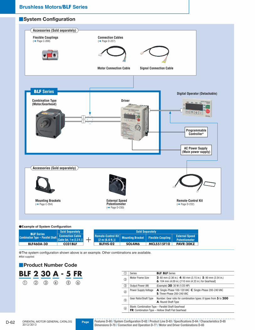
System Configuration ■
Accessories (Sold separately)
Accessories (Sold separately)
Remote-Control Kit (➜ Page D-232)
Combination Type(Motor/Gearhead)
Driver
Digital Operator (Detachable)
Mounting Brackets (➜ Page C-264)
External Speed Potentiometer(➜ Page D-230)
●Example of System Configuration
AC Power Supply (Main power supply)
ProgrammableController✽
Connection Cables(➜ Page D-227)
Flexible Couplings(➜ Page C-269)
Motor Connection Cable Signal Connection Cable
BLF Series
PAVR-20KZ
External Speed
Potentiometer
Remote-Control Kit
[2 m (6.6 ft.)]
BLFHS-02 SOL4M6
Flexible Coupling
MCL5515F10
Mounting BracketConnection Cable
[Cable Set, 1 m (3.3 ft.)]
CC01BLF
BLF Series
BLF460A-30
Combination Type - Parallel Shaft
Sold SeparatelySold Separately
Product Number Code ■
BLF 2 30 A - 5 FR① ② ③ ④ ⑤ ⑥
① Series BLF: BLF Series
②Motor Frame Size 2: 60 mm (2.36 in.) 4: 80 mm (3.15 in.) 5: 90 mm (3.54 in.)
6: 104 mm (4.09 in.) [110 mm (4.33 in.) for Gearhead]
③ Output Power (W) (Example) 30: 30 W (1/25 HP)
④Power Supply Voltage A: Single-Phase 100-120 VAC C: Single-Phase 200-240 VAC
S: Three-Phase 200-240 VAC
⑤Gear Ratio/Shaft Type Number: Gear ratio for combination types: 8 types from 5 to 200
A: Round Shaft Type
⑥Blank: Combination Type – Parallel Shaft Gearhead
FR: Combination Type – Hollow Shaft Flat Gearhead
●The system confi guration shown above is an example. Other combinations are available.✽Not supplied
D-63
Brushless Motors/AC Speed Control MotorsIn
trod
uctio
n
Bru
shless M
oto
rsA
C S
peed
Co
ntro
l Mo
tors
Accesso
riesIn
stallation
AC
Inp
ut
DC
Inp
ut
BH
FFE1
00/
FE200
ES01/
ES02
US
BX
BLF
BLE
BLU
BLH
BLV
CAD DataManuals
www.orientalmotor.com Technical Support
TEL: (800) 468-3982E-mail: [email protected]
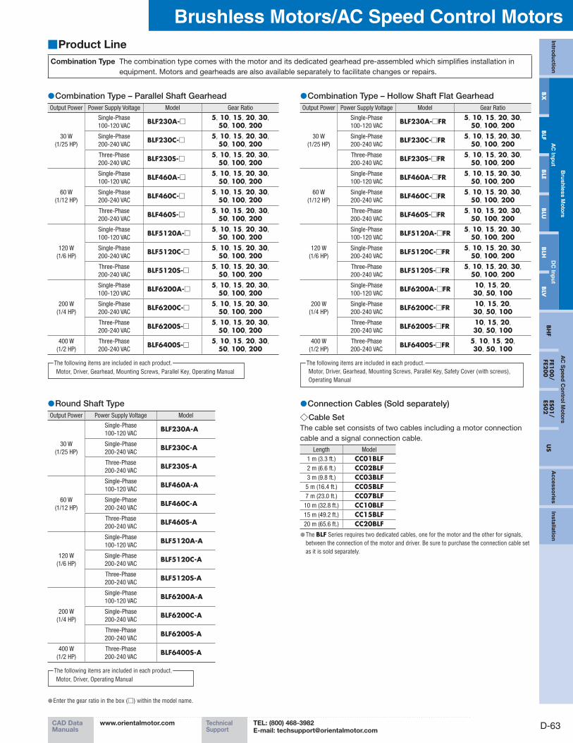
Combination Type – Parallel Shaft Gearhead ●Output Power Power Supply Voltage Model Gear Ratio
30 W
(1/25 HP)
Single-Phase
100-120 VAC BLF230A-□ 5, 10, 15, 20, 30,
50, 100, 200Single-Phase
200-240 VACBLF230C-□ 5, 10, 15, 20, 30,
50, 100, 200Three-Phase
200-240 VACBLF230S-□ 5, 10, 15, 20, 30,
50, 100, 200
60 W
(1/12 HP)
Single-Phase
100-120 VAC BLF460A-□ 5, 10, 15, 20, 30,
50, 100, 200Single-Phase
200-240 VACBLF460C-□ 5, 10, 15, 20, 30,
50, 100, 200Three-Phase
200-240 VACBLF460S-□ 5, 10, 15, 20, 30,
50, 100, 200
120 W
(1/6 HP)
Single-Phase
100-120 VAC BLF5120A-□ 5, 10, 15, 20, 30,
50, 100, 200Single-Phase
200-240 VACBLF5120C-□ 5, 10, 15, 20, 30,
50, 100, 200Three-Phase
200-240 VACBLF5120S-□ 5, 10, 15, 20, 30,
50, 100, 200
200 W
(1/4 HP)
Single-Phase
100-120 VAC BLF6200A-□ 5, 10, 15, 20, 30,
50, 100, 200Single-Phase
200-240 VACBLF6200C-□ 5, 10, 15, 20, 30,
50, 100, 200Three-Phase
200-240 VACBLF6200S-□ 5, 10, 15, 20, 30,
50, 100, 200400 W
(1/2 HP)
Three-Phase
200-240 VACBLF6400S-□ 5, 10, 15, 20, 30,
50, 100, 200
Motor, Driver, Gearhead, Mounting Screws, Parallel Key, Operating Manual
The following items are included in each product.
Combination Type – Hollow Shaft Flat Gearhead ●Output Power Power Supply Voltage Model Gear Ratio
30 W
(1/25 HP)
Single-Phase
100-120 VAC BLF230A-□FR 5, 10, 15, 20, 30,
50, 100, 200Single-Phase
200-240 VACBLF230C-□FR 5, 10, 15, 20, 30,
50, 100, 200Three-Phase
200-240 VACBLF230S-□FR 5, 10, 15, 20, 30,
50, 100, 200
60 W
(1/12 HP)
Single-Phase
100-120 VAC BLF460A-□FR 5, 10, 15, 20, 30,
50, 100, 200Single-Phase
200-240 VACBLF460C-□FR 5, 10, 15, 20, 30,
50, 100, 200Three-Phase
200-240 VACBLF460S-□FR 5, 10, 15, 20, 30,
50, 100, 200
120 W
(1/6 HP)
Single-Phase
100-120 VACBLF5120A-□FR 5, 10, 15, 20, 30,
50, 100, 200Single-Phase
200-240 VACBLF5120C-□FR 5, 10, 15, 20, 30,
50, 100, 200Three-Phase
200-240 VACBLF5120S-□FR 5, 10, 15, 20, 30,
50, 100, 200
200 W
(1/4 HP)
Single-Phase
100-120 VACBLF6200A-□FR 10, 15, 20,
30, 50, 100Single-Phase
200-240 VACBLF6200C-□FR 10, 15, 20,
30, 50, 100Three-Phase
200-240 VACBLF6200S-□FR 10, 15, 20,
30, 50, 100400 W
(1/2 HP)
Three-Phase
200-240 VACBLF6400S-□FR 5, 10, 15, 20,
30, 50, 100
Motor, Driver, Gearhead, Mounting Screws, Parallel Key, Safety Cover (with screws),
Operating Manual
The following items are included in each product.
Product Line ■
Combination Type The combination type comes with the motor and its dedicated gearhead pre-assembled which simplifies installation in
equipment. Motors and gearheads are also available separately to facilitate changes or repairs.
Enter the gear ratio in the box ( ● □) within the model name.
Round Shaft Type ●Output Power Power Supply Voltage Model
30 W
(1/25 HP)
Single-Phase
100-120 VAC BLF230A-A
Single-Phase
200-240 VACBLF230C-A
Three-Phase
200-240 VACBLF230S-A
60 W
(1/12 HP)
Single-Phase
100-120 VAC BLF460A-A
Single-Phase
200-240 VACBLF460C-A
Three-Phase
200-240 VACBLF460S-A
120 W
(1/6 HP)
Single-Phase
100-120 VAC BLF5120A-A
Single-Phase
200-240 VACBLF5120C-A
Three-Phase
200-240 VACBLF5120S-A
200 W
(1/4 HP)
Single-Phase
100-120 VAC BLF6200A-A
Single-Phase
200-240 VACBLF6200C-A
Three-Phase
200-240 VACBLF6200S-A
400 W
(1/2 HP)
Three-Phase
200-240 VACBLF6400S-A
Motor, Driver, Operating Manual
The following items are included in each product.
Connection Cables (Sold separately) ●Cable Set ◇
The cable set consists of two cables including a motor connection
cable and a signal connection cable.
Length Model
1 m (3.3 ft.) CC01BLF2 m (6.6 ft.) CC02BLF3 m (9.8 ft.) CC03BLF5 m (16.4 ft.) CC05BLF7 m (23.0 ft.) CC07BLF10 m (32.8 ft.) CC10BLF15 m (49.2 ft.) CC15BLF20 m (65.6 ft.) CC20BLF The ● BLF Series requires two dedicated cables, one for the motor and the other for signals,
between the connection of the motor and driver. Be sure to purchase the connection cable set
as it is sold separately.

PageORIENTAL MOTOR GENERAL CATALOG 2012/2013
D-64
Brushless Motors/BLF Series
Features D-60 / System Configuration D-62 / Product Line D-63 / Specifications D-64 / Characteristics D-65Dimensions D-70 / Connection and Operation D-77 / Motor and Driver Combinations D-83
Specifications ■
30 W (1/25 HP) ● Motor: / Driver:
Model
Combination Type – Parallel Shaft Gearhead BLF230A-□ BLF230C-□ BLF230S-□Combination Type – Hollow Shaft Flat Gearhead BLF230A-□FR BLF230C-□FR BLF230S-□FRRound Shaft Type BLF230A-A BLF230C-A BLF230S-A
Rated Output Power (Continuous) W (HP) 30 (1/25)
Power Source
Rated Voltage VAC Single-Phase 100-120 Single-Phase 200-240 Three-Phase 200-240
Permissible Voltage Range ±10%
Rated Frequency Hz 50/60
Permissible Frequency Range ±5%
Rated Input Current A 1.3 0.8 0.45
Maximum Input Current A 3.0 1.7 1.2
Rated Torque N·m (oz-in) 0.1 (14.2)
Starting Torque N·m (oz-in) 0.2 (28)
Rated Speed r/min 3000
Speed Control Range r/min 80∼4000
Round Shaft Type
Permissible Load Inertia J×10-4 kg·m2 (oz-in2) 1.8 (9.8)
Rotor Inertia J ×10-4 kg·m2 (oz-in2) 0.087 (0.48)
Speed Regulation✽
(When digital
operator is used)
Load ±0.2% max. (0∼Rated torque, at rated speed, at rated voltage, at normal ambient temperature)
Voltage ±0.2% max. (Rated voltage ±10%, at rated speed, with no load, at normal ambient temperature)
Temperature ±0.2% max. [0∼+50˚C (+32∼+122˚F), at rated speed, with no load, at rated voltage]
60 W (1/12 HP) ● Motor: / Driver:
Model
Combination Type – Parallel Shaft Gearhead BLF460A-□ BLF460C-□ BLF460S-□Combination Type – Hollow Shaft Flat Gearhead BLF460A-□FR BLF460C-□FR BLF460S-□FRRound Shaft Type BLF460A-A BLF460C-A BLF460S-A
Rated Output Power (Continuous) W (HP) 60 (1/12)
Power Source
Rated Voltage VAC Single-Phase 100-120 Single-Phase 200-240 Three-Phase 200-240
Permissible Voltage Range ±10%
Rated Frequency Hz 50/60
Permissible Frequency Range ±5%
Rated Input Current A 2.0 1.2 0.7
Maximum Input Current A 4.5 3.0 1.5
Rated Torque N·m (oz-in) 0.2 (28)
Starting Torque N·m (oz-in) 0.4 (56)
Rated Speed r/min 3000
Speed Control Range r/min 80∼4000
Round Shaft Type
Permissible Load Inertia J×10-4 kg·m2 (oz-in2) 3.75 (21)
Rotor Inertia J ×10-4 kg·m2 (oz-in2) 0.24 (1.31)
Speed Regulation✽
(When digital
operator is used)
Load ±0.2% max. (0∼Rated torque, at rated speed, at rated voltage, at normal ambient temperature)
Voltage ±0.2% max. (Rated voltage ±10%, at rated speed, with no load, at normal ambient temperature)
Temperature ±0.2% max. [0∼+50˚C (+32∼+122˚F), at rated speed, with no load, at rated voltage]
120 W (1/6 HP) ● Motor: / Driver:
Model
Combination Type – Parallel Shaft Gearhead BLF5120A-□ BLF5120C-□ BLF5120S-□Combination Type – Hollow Shaft Flat Gearhead BLF5120A-□FR BLF5120C-□FR BLF5120S-□FRRound Shaft Type BLF5120A-A BLF5120C-A BLF5120S-A
Rated Output Power (Continuous) W (HP) 120 (1/6)
Power Source
Rated Voltage VAC Single-Phase 100-120 Single-Phase 200-240 Three-Phase 200-240
Permissible Voltage Range ±10%
Rated Frequency Hz 50/60
Permissible Frequency Range ±5%
Rated Input Current A 3.3 2.0 1.1
Maximum Input Current A 7.0 4.5 2.5
Rated Torque N·m (oz-in) 0.4 (56)
Starting Torque N·m (oz-in) 0.8 (113)
Rated Speed r/min 3000
Speed Control Range r/min 80∼4000
Round Shaft Type
Permissible Load Inertia J×10-4 kg·m2 (oz-in2) 5.6 (31)
Rotor Inertia J ×10-4 kg·m2 (oz-in2) 0.61 (3.3)
Speed Regulation✽
(When digital
operator is used)
Load ±0.2% max. (0∼Rated torque, at rated speed, at rated voltage, at normal ambient temperature)
Voltage ±0.2% max. (Rated voltage ±10%, at rated speed, with no load, at normal ambient temperature)
Temperature ±0.2% max. [0∼+50˚C (+32∼+122˚F), at rated speed, with no load, at rated voltage]
Speed regulation values vary depending on the speed setting method. ✽
Settings from internal speed potentiometer, external speed potentiometer, external DC voltage; Load: ±0.5% max., Voltage: ±0.5% max., Temperature: ±0.5% max.
The values for each specification apply to the motor only. ●
Enter the gear ratio in the box ( ● □) within the model name.
D-65
Brushless Motors/AC Speed Control MotorsIn
trod
uctio
n
Bru
shless M
oto
rsA
C S
peed
Co
ntro
l Mo
tors
Accesso
riesIn
stallation
AC
Inp
ut
DC
Inp
ut
BH
FFE1
00/
FE200
ES01/
ES02
US
BX
BLF
BLE
BLU
BLH
BLV
CAD DataManuals
www.orientalmotor.com Technical Support
TEL: (800) 468-3982E-mail: [email protected]
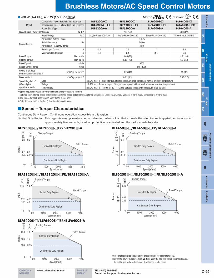
200 W (1/4 HP), 400 W (1/2 HP) ● Motor: / Driver:
Model
Combination Type – Parallel Shaft Gearhead BLF6200A-□ BLF6200C-□ BLF6200S-□ BLF6400S-□Combination Type – Hollow Shaft Flat Gearhead BLF6200A-□FR BLF6200C-□FR BLF6200S-□FR BLF6400S-□FRRound Shaft Type BLF6200A-A BLF6200C-A BLF6200S-A BLF6400S-A
Rated Output Power (Continuous) W (HP) 200 (1/4) 400 (1/2)
Power Source
Rated Voltage VAC Single-Phase 100-120 Single-Phase 200-240 Three-Phase 200-240 Three-Phase 200-240
Permissible Voltage Range ±10%
Rated Frequency Hz 50/60
Permissible Frequency Range ±5%
Rated Input Current A 4.7 2.8 1.7 2.8
Maximum Input Current A 8.8 5.1 3.4 5.6
Rated Torque N·m (oz-in) 0.65 (92) 1.3 (184)
Starting Torque N·m (oz-in) 1.15 (163) 1.8 (250)
Rated Speed r/min 3000
Speed Control Range r/min 80∼4000
Round Shaft Type
Permissible Load Inertia J×10-4 kg·m2 (oz-in2) 8.75 (48) 15 (82)
Rotor Inertia J ×10-4 kg·m2 (oz-in2) 0.61 (3.3) 0.66 (3.6)
Speed Regulation✽
(When digital
operator is used)
Load ±0.2% max. (0∼Rated torque, at rated speed, at rated voltage, at normal ambient temperature)
Voltage ±0.2% max. (Rated voltage ±10%, at rated speed, with no load, at normal ambient temperature)
Temperature ±0.2% max. [0∼+50˚C (+32∼+122˚F), at rated speed, with no load, at rated voltage]
Speed regulation values vary depending on the speed setting method. ✽
Settings from internal speed potentiometer, external speed potentiometer, external DC voltage; Load: ±0.5% max., Voltage: ±0.5% max., Temperature: ±0.5% max.
The values for each specification apply to the motor only. ●Enter the gear ratio in the box ( ● □) within the model name.
Speed – Torque Characteristics ■
Continuous Duty Region: Continuous operation is possible in this region.
Limited Duty Region: This region is used primarily when accelerating. When a load that exceeds the rated torque is applied continuously for
approximately five seconds, overload protection is activated and the motor coasts to a stop.
BLF230■□-□/BLF230■□-□FR/BLF230■□-A BLF460■□-□/BLF460■□-□FR/BLF460■□-A
40000
Continuous Duty Region
Limited Duty Region
1000 2000 3000
0.075
0.1
0.228
14.2
10.6
080
Rated Torque
Starting Torque
Speed [r/min]
[ N· m
]
[oz-
in]
Torq
ue
40001000 2000 300080
0.2
0.4
0.15
0
Continuous Duty Region
Limited Duty RegionRated Torque
Starting Torque
Speed [r/min]
[ N· m
]
56
28
21
0
[oz-
in]
Torq
ue
BLF5120■□-□/BLF5120■□-□FR/BLF5120■□-A BLF6200■□-□/BLF6200■□-□FR/BLF6200■□-A
40001000 2000 300080
0.4
0.8
0.3
0
Continuous Duty Region
Limited Duty RegionRated Torque
Starting Torque
Speed [r/min]
[ N· m
]
113
56
42
0
[oz-
in]
Torq
ue
40001000 2000 300080
Rated Torque
Starting Torque
Speed [r/min]
0.65
00
Continuous Duty Region
Limited Duty Region
1.15163
0.4563
92
Torq
ue
[ N· m
]
[ oz-
in]
BLF6400S-□/BLF6400S-□FR/BLF6400S-A
40001000 2000 300080
Rated Torque
Starting Torque
Speed [r/min]
00
Continuous Duty Region
Limited Duty Region
1.8
1.3
0.95
184
134
250
[ N· m
]
[ oz-
in]
Torq
ue
The characteristics shown above are applicable for the motors only. ●Enter the power supply voltage ( ● A, C or S) in the box (■□) within the model name.
Enter the gear ratio in the box (□) within the model name.

PageORIENTAL MOTOR GENERAL CATALOG 2012/2013
D-66
Brushless Motors/BLF Series
Features D-60 / System Configuration D-62 / Product Line D-63 / Specifications D-64 / Characteristics D-65Dimensions D-70 / Connection and Operation D-77 / Motor and Driver Combinations D-83
Common Specifications ■
Item Specifications
Speed Setting Methods
Select one of the following methods: · Set using the internal speed potentiometer· Set using the digital operator: Up to eight speeds· Set using an accessory external speed potentiometer: PAVR-20KZ (20 kΩ, 1/4 W) (sold separately)· Set using external DC voltage: 0∼5 VDC or 0∼10 VDC
Acceleration/Deceleration Time
(At 3000 r/min) 0.2∼15 sec. (factory setting: 0.5 sec.) Up to eight speeds using the digital operator
Input Signals (In the remote mode)
Photocoupler input Input resistance 3.3 kΩInternal power supply voltage: 14 VDC±10%
Connectable external voltage: 24 VDC±10% (only for source logic)
Sink input (factory setting), Source input/2-wire input mode (factory setting), or 3-wire input mode
CW [START/STOP] input, CCW [RUN/BRAKE] input, STOP-MODE [CW/CCW] input, Speed data select, Alarm reset input, External error input
Names in [ ] apply in the 3-wire input mode.
Output SignalsOpen-collector output 4.5∼26.4 VDC, 10 mA max. (5∼10 mA for Speed output)
Speed output (30 pulses/rotation), Alarm output1, Alarm output2
Protective Functions✽
When the following are activated, the "Alarm" signal will be output and the motor will coast to a stop. (The motor will stop instantaneously when an
external error is input.) · Overload protection: Activated when the motor load exceeds rated torque for a minimum of 5 seconds.· Overvoltage protection: Activated when the voltage applied to the driver exceeds 120 VAC or 240 VAC by a minimum of 20%, a gravitational operation
is performed or a load exceeding the permissible load inertia is driven.· Undervoltage protection: Activated when the voltage applied to the driver falls below 100 VAC or 200 VAC by a minimum of 40%.· Motor sensor error: Activated when an error is detected in the signals received from the motor due to improper connection or disconnection of the
signal cable, etc. · Overspeed protection: Activated when the speed of the motor shaft exceeds 4800 r/min.· Overcurrent protection: Activated when an excessive current flows through the driver due to a ground fault, etc.· CPU error, EEPROM error, External error, Operation error
Maximum Cable Extension Distance Motor/Driver Distance: 20.4 m (66.9 ft.) (when a dedicated connection cable is used)
Time Rating Continuous
With the ✽ BLF Series, the motor speed cannot be controlled in a gravitational operation or other application where the motor shaft is turned by the load.
When a load exceeding the permissible load inertia is driven or a gravitational operation is performed, the overvoltage protective function will be activated and the motor will coast to a stop.
General Specifications ■
Item Motor Driver
Insulation Resistance
100 MΩ or more when 500 VDC megger is applied between the
windings and the case after continuous operation under normal
ambient temperature and humidity.
100 MΩ or more when 500 VDC megger is applied between the power supply
terminal and the protective earth terminal, and between the power supply terminal
and the I/O terminal after continuous operation under normal ambient temperature
and humidity.
Dielectric Strength
Sufficient to withstand 1.5 kVAC at 50 Hz applied between the
windings and the case for 1 minute after continuous operation
under normal ambient temperature and humidity.
Sufficient to withstand 1.8 kVAC at 50 Hz applied between the power supply
terminal and the protective earth terminal for 1 minute, and 3 kVAC at 50 Hz
applied between the power supply terminal and the I/O terminal for 1 minute after
continuous operation under normal ambient temperature and humidity.
Temperature Rise
Temperature rise of the windings and the case are 50˚C (90˚F)
or less, and 40˚C (72˚F) or less✽1 respectively measured by the
thermocouple method after continuous operation under normal
ambient temperature and humidity.
Temperature rise of heat sink is 50˚C (90˚F) or less measured by the thermocouple
method after continuous operation under normal ambient temperature and
humidity.
Operating
Environment
Ambient Temperature 0∼+50˚C (+32∼+122˚F) (non-freezing)
Ambient Humidity 85% or less (non-condensing)
Altitude Up to 1000 m (3300 ft.) above sea level
Atmosphere No corrosive gases or dust. Cannot be used in a radioactive area, magnetic field, vacuum or other special environment
Vibration
Not subject to continuous vibration or excessive impact
In conformance with JIS C 60068-2-6, "Sine-wave vibration test method"
Frequency range: 10∼55 Hz Pulsating amplitude: 0.15 mm (0.006 in.)
Sweep direction: 3 directions (X, Y, Z) Number of sweeps: 20 times
Storage
Condition✽2
Ambient Temperature −25∼+70˚C (−13∼+158˚F) (non-freezing)
Ambient Humidity 85% or less (non-condensing)
Altitude Up to 3000 m (10000 ft.) above sea level
Thermal Class UL/CSA standards: 105 (A), EN standards: 120 (E) −
Degree of ProtectionIP65 (Excluding the mounting surface of the round shaft type and
connectors)IP20
1 For round shaft types, please attach to the heat radiation plate (material: aluminum) of the following sizes to maintain a maximum motor case temperature of 90˚C (194˚F). ✽
BLF230■□-A: 115×115 mm (4.53×4.53 in.), 5 mm (0.20 in.) thick BLF460■□-A: 135×135 mm (5.31×5.31 in.), 5 mm (0.20 in.) thick
BLF5120■□-A: 165×165 mm (6.50×6.50 in.), 5 mm (0.20 in.) thick BLF6200■□-A: 200×200 mm (7.87×7.87 in.), 5 mm (0.20 in.) thick
BLF6400S-A: 250×250 mm (9.84×9.84 in.), 6 mm (0.24 in.) thick
●Enter the power supply voltage (A, C or S) in the box (■□) within the model name.
2 The storage condition applies to a short period such as a period during transportation. ✽
Note
Do not measure insulation resistance or perform the dielectric strength test while the motor and driver are connected. ●
D-67
Brushless Motors/AC Speed Control MotorsIn
trod
uctio
n
Bru
shless M
oto
rsA
C S
peed
Co
ntro
l Mo
tors
Accesso
riesIn
stallation
AC
Inp
ut
DC
Inp
ut
BH
FFE1
00/
FE200
ES01/
ES02
US
BX
BLF
BLE
BLU
BLH
BLV
CAD DataManuals
www.orientalmotor.com Technical Support
TEL: (800) 468-3982E-mail: [email protected]
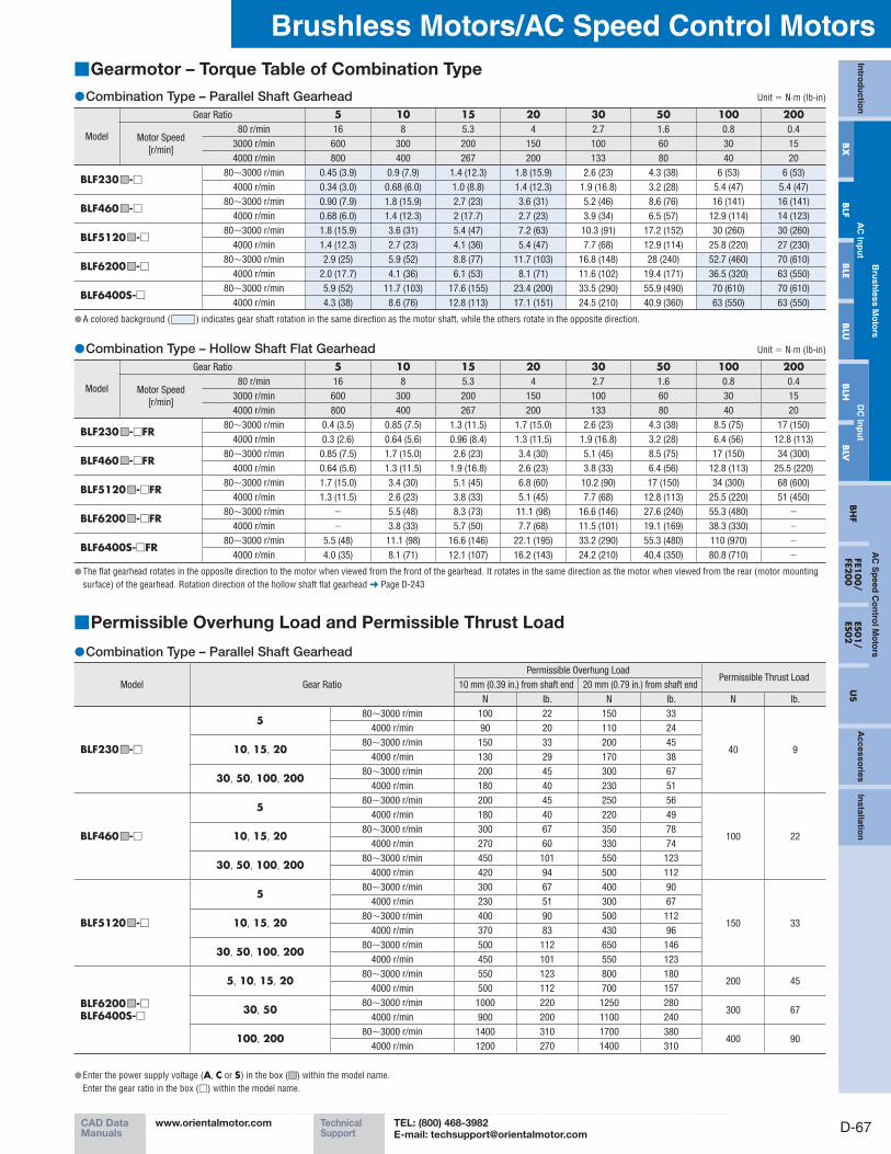
Gearmotor – Torque Table of Combination Type ■
Combination Type – Parallel Shaft Gearhead ● Unit = N·m (lb-in)
Model
Gear Ratio 5 10 15 20 30 50 100 200
Motor Speed
[r/min]
80 r/min 16 8 5.3 4 2.7 1.6 0.8 0.4
3000 r/min 600 300 200 150 100 60 30 15
4000 r/min 800 400 267 200 133 80 40 20
BLF230■□-□80∼3000 r/min 0.45 (3.9) 0.9 (7.9) 1.4 (12.3) 1.8 (15.9) 2.6 (23) 4.3 (38) 6 (53) 6 (53)
4000 r/min 0.34 (3.0) 0.68 (6.0) 1.0 (8.8) 1.4 (12.3) 1.9 (16.8) 3.2 (28) 5.4 (47) 5.4 (47)
BLF460■□-□80∼3000 r/min 0.90 (7.9) 1.8 (15.9) 2.7 (23) 3.6 (31) 5.2 (46) 8.6 (76) 16 (141) 16 (141)
4000 r/min 0.68 (6.0) 1.4 (12.3) 2 (17.7) 2.7 (23) 3.9 (34) 6.5 (57) 12.9 (114) 14 (123)
BLF5120■□-□80∼3000 r/min 1.8 (15.9) 3.6 (31) 5.4 (47) 7.2 (63) 10.3 (91) 17.2 (152) 30 (260) 30 (260)
4000 r/min 1.4 (12.3) 2.7 (23) 4.1 (36) 5.4 (47) 7.7 (68) 12.9 (114) 25.8 (220) 27 (230)
BLF6200■□-□80∼3000 r/min 2.9 (25) 5.9 (52) 8.8 (77) 11.7 (103) 16.8 (148) 28 (240) 52.7 (460) 70 (610)
4000 r/min 2.0 (17.7) 4.1 (36) 6.1 (53) 8.1 (71) 11.6 (102) 19.4 (171) 36.5 (320) 63 (550)
BLF6400S-□80∼3000 r/min 5.9 (52) 11.7 (103) 17.6 (155) 23.4 (200) 33.5 (290) 55.9 (490) 70 (610) 70 (610)
4000 r/min 4.3 (38) 8.6 (76) 12.8 (113) 17.1 (151) 24.5 (210) 40.9 (360) 63 (550) 63 (550)
A colored background ( ● ) indicates gear shaft rotation in the same direction as the motor shaft, while the others rotate in the opposite direction.
Combination Type – Hollow Shaft Flat Gearhead ● Unit = N·m (lb-in)
Model
Gear Ratio 5 10 15 20 30 50 100 200
Motor Speed
[r/min]
80 r/min 16 8 5.3 4 2.7 1.6 0.8 0.4
3000 r/min 600 300 200 150 100 60 30 15
4000 r/min 800 400 267 200 133 80 40 20
BLF230■□-□FR80∼3000 r/min 0.4 (3.5) 0.85 (7.5) 1.3 (11.5) 1.7 (15.0) 2.6 (23) 4.3 (38) 8.5 (75) 17 (150)
4000 r/min 0.3 (2.6) 0.64 (5.6) 0.96 (8.4) 1.3 (11.5) 1.9 (16.8) 3.2 (28) 6.4 (56) 12.8 (113)
BLF460■□-□FR80∼3000 r/min 0.85 (7.5) 1.7 (15.0) 2.6 (23) 3.4 (30) 5.1 (45) 8.5 (75) 17 (150) 34 (300)
4000 r/min 0.64 (5.6) 1.3 (11.5) 1.9 (16.8) 2.6 (23) 3.8 (33) 6.4 (56) 12.8 (113) 25.5 (220)
BLF5120■□-□FR80∼3000 r/min 1.7 (15.0) 3.4 (30) 5.1 (45) 6.8 (60) 10.2 (90) 17 (150) 34 (300) 68 (600)
4000 r/min 1.3 (11.5) 2.6 (23) 3.8 (33) 5.1 (45) 7.7 (68) 12.8 (113) 25.5 (220) 51 (450)
BLF6200■□-□FR80∼3000 r/min − 5.5 (48) 8.3 (73) 11.1 (98) 16.6 (146) 27.6 (240) 55.3 (480) −
4000 r/min − 3.8 (33) 5.7 (50) 7.7 (68) 11.5 (101) 19.1 (169) 38.3 (330) −
BLF6400S-□FR80∼3000 r/min 5.5 (48) 11.1 (98) 16.6 (146) 22.1 (195) 33.2 (290) 55.3 (480) 110 (970) −
4000 r/min 4.0 (35) 8.1 (71) 12.1 (107) 16.2 (143) 24.2 (210) 40.4 (350) 80.8 (710) −
The flat gearhead rotates in the opposite direction to the motor when viewed from the front of the gearhead. It rotates in the same direction as the motor when viewed from the rear (motor mounting ●surface) of the gearhead. Rotation direction of the hollow shaft flat gearhead ➜ Page D-243
Permissible Overhung Load and Permissible Thrust Load ■
Combination Type – Parallel Shaft Gearhead ●
Model Gear Ratio
Permissible Overhung LoadPermissible Thrust Load
10 mm (0.39 in.) from shaft end 20 mm (0.79 in.) from shaft end
N lb. N lb. N lb.
BLF230■□-□
580∼3000 r/min 100 22 150 33
40 9
4000 r/min 90 20 110 24
10, 15, 2080∼3000 r/min 150 33 200 45
4000 r/min 130 29 170 38
30, 50, 100, 20080∼3000 r/min 200 45 300 67
4000 r/min 180 40 230 51
BLF460■□-□
580∼3000 r/min 200 45 250 56
100 22
4000 r/min 180 40 220 49
10, 15, 2080∼3000 r/min 300 67 350 78
4000 r/min 270 60 330 74
30, 50, 100, 20080∼3000 r/min 450 101 550 123
4000 r/min 420 94 500 112
BLF5120■□-□
580∼3000 r/min 300 67 400 90
150 33
4000 r/min 230 51 300 67
10, 15, 2080∼3000 r/min 400 90 500 112
4000 r/min 370 83 430 96
30, 50, 100, 20080∼3000 r/min 500 112 650 146
4000 r/min 450 101 550 123
BLF6200■□-□BLF6400S-□
5, 10, 15, 2080∼3000 r/min 550 123 800 180
200 454000 r/min 500 112 700 157
30, 5080∼3000 r/min 1000 220 1250 280
300 674000 r/min 900 200 1100 240
100, 20080∼3000 r/min 1400 310 1700 380
400 904000 r/min 1200 270 1400 310
Enter the power supply voltage ( ● A, C or S) in the box (■□) within the model name.
Enter the gear ratio in the box (□) within the model name.

PageORIENTAL MOTOR GENERAL CATALOG 2012/2013
D-68
Brushless Motors/BLF Series
Features D-60 / System Configuration D-62 / Product Line D-63 / Specifications D-64 / Characteristics D-65Dimensions D-70 / Connection and Operation D-77 / Motor and Driver Combinations D-83
Combination Type – Hollow Shaft Flat Gearhead ●
Model Gear Ratio
Permissible Overhung Load
Permissible Thrust Load10 mm (0.39 in.) from mounting
surface of gearhead
20 mm (0.79 in.) from mounting
surface of gearhead
N lb. N lb. N lb.
BLF230■□-□FR5, 10
80∼3000 r/min 450 101 370 83
200 454000 r/min 410 92 330 74
15, 20, 30, 50, 100, 20080∼3000 r/min 500 112 400 90
4000 r/min 460 103 370 83
BLF460■□-□FR5, 10
80∼3000 r/min 800 180 660 148
400 904000 r/min 730 164 600 135
15, 20, 30, 50, 100, 20080∼3000 r/min 1200 270 1000 220
4000 r/min 1100 240 910 200
BLF5120■□-□FR
5, 1080∼3000 r/min 900 200 770 173
500 112
4000 r/min 820 184 700 157
15, 2080∼3000 r/min 1300 290 1110 240
4000 r/min 1200 270 1020 220
30, 50, 100, 20080∼3000 r/min 1500 330 1280 280
4000 r/min 1400 310 1200 270
BLF6200■□-□FRBLF6400S-□FR
5✽, 1080∼3000 r/min 1230 270 1070 240
800 180
4000 r/min 1130 250 990 220
15, 2080∼3000 r/min 1680 370 1470 330
4000 r/min 1550 340 1360 300
30, 50, 10080∼3000 r/min 2040 450 1780 400
4000 r/min 1900 420 1660 370
Only the ✽ BLF6400S-□FR is supported.
The permissible overhung load can also be calculated with a formula. Permissible overhung load calculation ● ➜ Page D-242
Round Shaft Type ●
Model
Permissible Overhung Load
Permissible Thrust Load10 mm (0.39 in.) from shaft end 20 mm (0.79 in.) from shaft end
N lb. N lb.
BLF230■□-A 80 18 100 22
The permissible thrust load
should not be greater than
half the motor mass.
BLF460■□-A 110 24 130 29
BLF5120■□-A 150 33 170 38
BLF6200■□-ABLF6400S-A 197 44 221 49
Enter the power supply voltage ( ● A, C or S) in the box (■□) within the model name.
Enter the gear ratio in the box (□) within the model name.
D-69
Brushless Motors/AC Speed Control MotorsIn
trod
uctio
n
Bru
shless M
oto
rsA
C S
peed
Co
ntro
l Mo
tors
Accesso
riesIn
stallation
AC
Inp
ut
DC
Inp
ut
BH
FFE1
00/
FE200
ES01/
ES02
US
BX
BLF
BLE
BLU
BLH
BLV
CAD DataManuals
www.orientalmotor.com Technical Support
TEL: (800) 468-3982E-mail: [email protected]
Enter the power supply voltage ( ● A, C or S) in the box (■□) within the model name.
Enter the gear ratio in the box (□) within the model name.
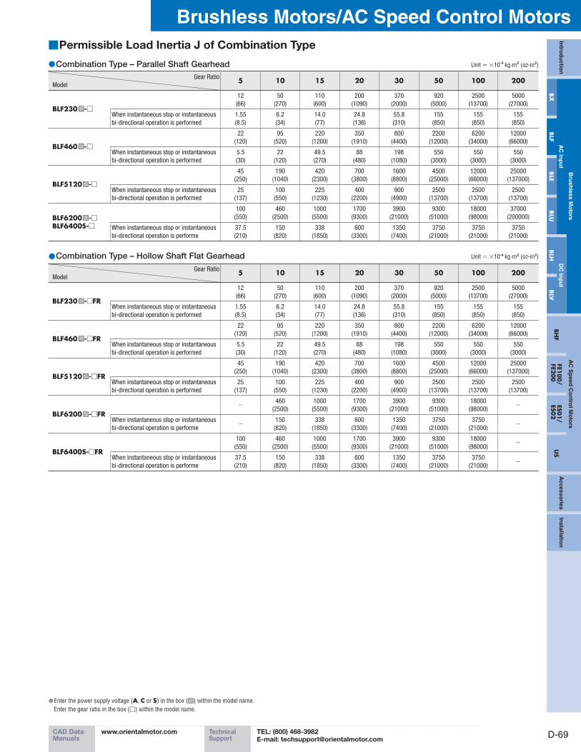
Permissible Load Inertia J of Combination Type ■
Combination Type – Parallel Shaft Gearhead ● Unit = ×10-4 kg·m2 (oz-in2)
Gear Ratio
Model5 10 15 20 30 50 100 200
BLF230■□-□
12
(66)
50
(270)
110
(600)
200
(1090)
370
(2000)
920
(5000)
2500
(13700)
5000
(27000)
When instantaneous stop or instantaneous
bi-directional operation is performed
1.55
(8.5)
6.2
(34)
14.0
(77)
24.8
(136)
55.8
(310)
155
(850)
155
(850)
155
(850)
BLF460■□-□
22
(120)
95
(520)
220
(1200)
350
(1910)
800
(4400)
2200
(12000)
6200
(34000)
12000
(66000)
When instantaneous stop or instantaneous
bi-directional operation is performed
5.5
(30)
22
(120)
49.5
(270)
88
(480)
198
(1080)
550
(3000)
550
(3000)
550
(3000)
BLF5120■□-□
45
(250)
190
(1040)
420
(2300)
700
(3800)
1600
(8800)
4500
(25000)
12000
(66000)
25000
(137000)
When instantaneous stop or instantaneous
bi-directional operation is performed
25
(137)
100
(550)
225
(1230)
400
(2200)
900
(4900)
2500
(13700)
2500
(13700)
2500
(13700)
BLF6200■□-□BLF6400S-□
100
(550)
460
(2500)
1000
(5500)
1700
(9300)
3900
(21000)
9300
(51000)
18000
(98000)
37000
(200000)
When instantaneous stop or instantaneous
bi-directional operation is performe
37.5
(210)
150
(820)
338
(1850)
600
(3300)
1350
(7400)
3750
(21000)
3750
(21000)
3750
(21000)
Combination Type – Hollow Shaft Flat Gearhead ● Unit = ×10-4 kg·m2 (oz-in2)
Gear Ratio
Model5 10 15 20 30 50 100 200
BLF230■□-□FR
12
(66)
50
(270)
110
(600)
200
(1090)
370
(2000)
920
(5000)
2500
(13700)
5000
(27000)
When instantaneous stop or instantaneous
bi-directional operation is performed
1.55
(8.5)
6.2
(34)
14.0
(77)
24.8
(136)
55.8
(310)
155
(850)
155
(850)
155
(850)
BLF460■□-□FR
22
(120)
95
(520)
220
(1200)
350
(1910)
800
(4400)
2200
(12000)
6200
(34000)
12000
(66000)
When instantaneous stop or instantaneous
bi-directional operation is performed
5.5
(30)
22
(120)
49.5
(270)
88
(480)
198
(1080)
550
(3000)
550
(3000)
550
(3000)
BLF5120■□-□FR
45
(250)
190
(1040)
420
(2300)
700
(3800)
1600
(8800)
4500
(25000)
12000
(66000)
25000
(137000)
When instantaneous stop or instantaneous
bi-directional operation is performed
25
(137)
100
(550)
225
(1230)
400
(2200)
900
(4900)
2500
(13700)
2500
(13700)
2500
(13700)
BLF6200■□-□FR−
460
(2500)
1000
(5500)
1700
(9300)
3900
(21000)
9300
(51000)
18000
(98000)−
When instantaneous stop or instantaneous
bi-directional operation is performe−
150
(820)
338
(1850)
600
(3300)
1350
(7400)
3750
(21000)
3750
(21000)−
BLF6400S-□FR
100
(550)
460
(2500)
1000
(5500)
1700
(9300)
3900
(21000)
9300
(51000)
18000
(98000)−
When instantaneous stop or instantaneous
bi-directional operation is performe
37.5
(210)
150
(820)
338
(1850)
600
(3300)
1350
(7400)
3750
(21000)
3750
(21000)−
PageORIENTAL MOTOR GENERAL CATALOG 2012/2013
D-70
Brushless Motors/BLF Series
Features D-60 / System Configuration D-62 / Product Line D-63 / Specifications D-64 / Characteristics D-65Dimensions D-70 / Connection and Operation D-77 / Motor and Driver Combinations D-83
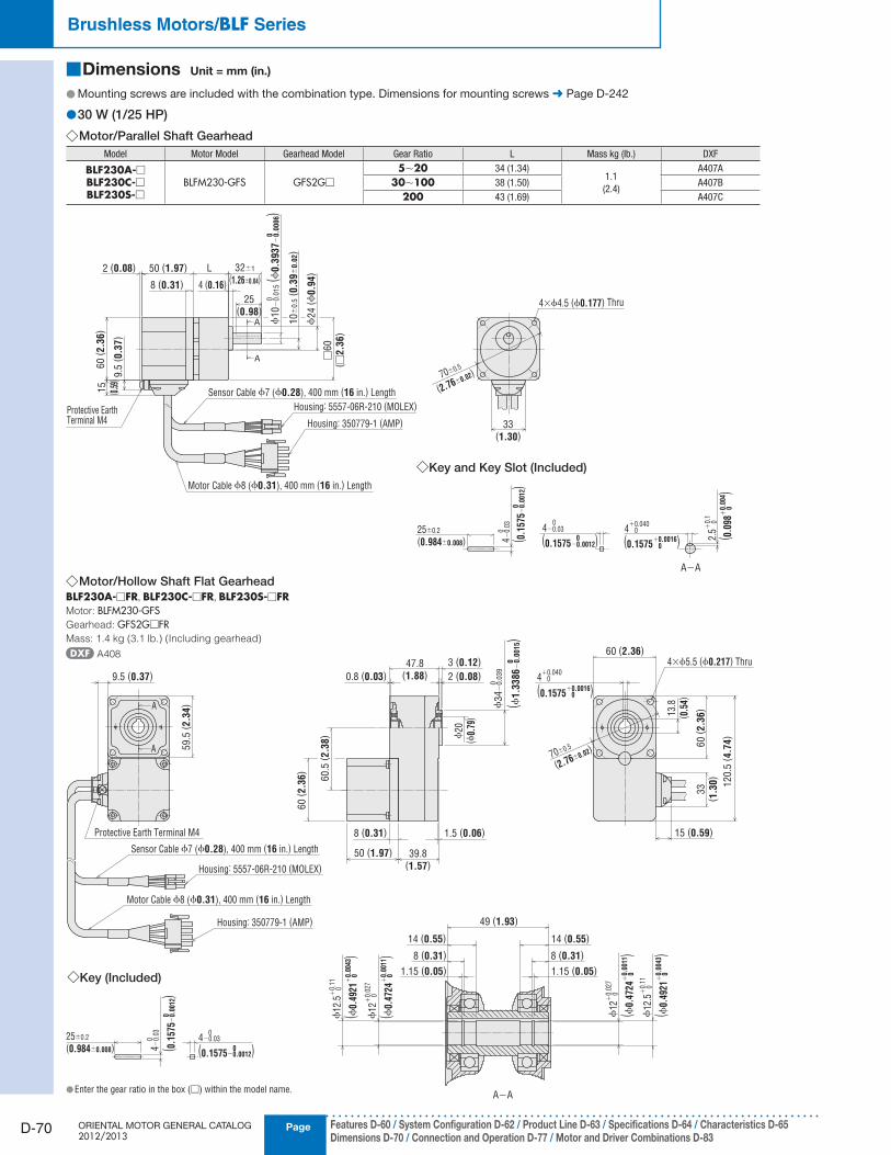
Dimensions ■ Unit = mm (in.)
Mounting screws are included with the combination type. Dimensions for mounting screws ● ➜ Page D-242
30 W (1/25 HP) ●Motor/Parallel Shaft Gearhead ◇
Model Motor Model Gearhead Model Gear Ratio L Mass kg (Ib.) DXF
BLF230A-□BLF230C-□BLF230S-□
BLFM230-GFS GFS2G□
5∼20 34 (1.34)1.1
(2.4)
A407A
30∼100 38 (1.50) A407B
200 43 (1.69) A407C
A
A
60
( 2.3
6)
15
( 0.5
9)
2 (0.08)
9.5
( 0.3
7)
Housing: 5557-06R-210 (MOLEX)
Housing: 350779-1 (AMP) 33(1.30)
50 (1.97) 32±1
(1.26±0.04)L
8 (0.31) 4 (0.16)
25(0.98)
10
±0
.5( 0
.39
±0
.02)
70±0.5
(2.76±0.02)
□60
( □2.3
6)
ϕ10
−0.0
15
( ϕ0.3
937
−0.0
006)
00
Sensor Cable ϕ7 (ϕ0.28), 400 mm (16 in.) Length
Motor Cable ϕ8 (ϕ0.31), 400 mm (16 in.) Length
25±0.2
(0.984±0.008)
A−A
◇Key and Key Slot (Included)
Protective EarthTerminal M4
4×ϕ4.5 (ϕ0.177) Thru
4−0.
030
0 4+0.040
0
04−0.03
0
0
2.5+
0.1
0
0
ϕ24
(ϕ0.9
4)
(0.1575−0.0012) (0.1575+0.0016) ( 0
.098
+0.
004 )
( 0.1
575−
0.00
12)
Motor/Hollow Shaft Flat Gearhead ◇BLF230A-□FR, BLF230C-□FR, BLF230S-□FRMotor: BLFM230-GFSGearhead: GFS2G□FRMass: 1.4 kg (3.1 lb.) (Including gearhead)
A408
A
A
◇Key (Included)
A−A
59.5
( 2.3
4)
9.5 (0.37)
Housing: 5557-06R-210 (MOLEX)
Housing: 350779-1 (AMP)
Sensor Cable ϕ7 (ϕ0.28), 400 mm (16 in.) Length
Motor Cable ϕ8 (ϕ0.31), 400 mm (16 in.) Length
Protective Earth Terminal M4
60
( 2.3
6)
60.5
( 2.3
8)
1.5 (0.06)8 (0.31)
3 (0.12)
2 (0.08)
39.8(1.57)
50 (1.97)
47.8(1.88)0.8 (0.03)
ϕ20
(ϕ0.
79)
ϕ34
−0.0
39
( ϕ1.3
386
−0.0
015)
0
0
4+0.040
(0.1575+0.0016)0
0
70±0.5
(2.76±0.02)
60 (2.36)4×ϕ5.5 (ϕ0.217) Thru
13.8
( 0.5
4)
33
( 1.3
0)
120.5
( 4.7
4)
60
( 2.3
6)
15 (0.59)
25±0.2
(0.984±0.008) 4−0.
03
0
0 4−0.03
0
0
(0.1575−0.0012)
14 (0.55) 14 (0.55)
49 (1.93)
8 (0.31) 8 (0.31)
1.15 (0.05) 1.15 (0.05)
ϕ12
+0.
027
( ϕ0.
4724
+0.
0011
)0
0
ϕ12
+0.
027
( ϕ0.
4724
+0.
0011
)0
0
ϕ12
.5+
0.11
( ϕ0.
4921
+0.
0043
)0
0
ϕ12
.5+
0.11
( ϕ0.
4921
+0.
0043
)0
0
( 0.1
575−
0.00
12)
Enter the gear ratio in the box ( ● □) within the model name.
D-71
Brushless Motors/AC Speed Control MotorsIn
trod
uctio
n
Bru
shless M
oto
rsA
C S
peed
Co
ntro
l Mo
tors
Accesso
riesIn
stallation
AC
Inp
ut
DC
Inp
ut
BH
FFE1
00/
FE200
ES01/
ES02
US
BX
BLF
BLE
BLU
BLH
BLV
CAD DataManuals
www.orientalmotor.com Technical Support
TEL: (800) 468-3982E-mail: [email protected]
Enter the gear ratio in the box ( ● □) within the model name.
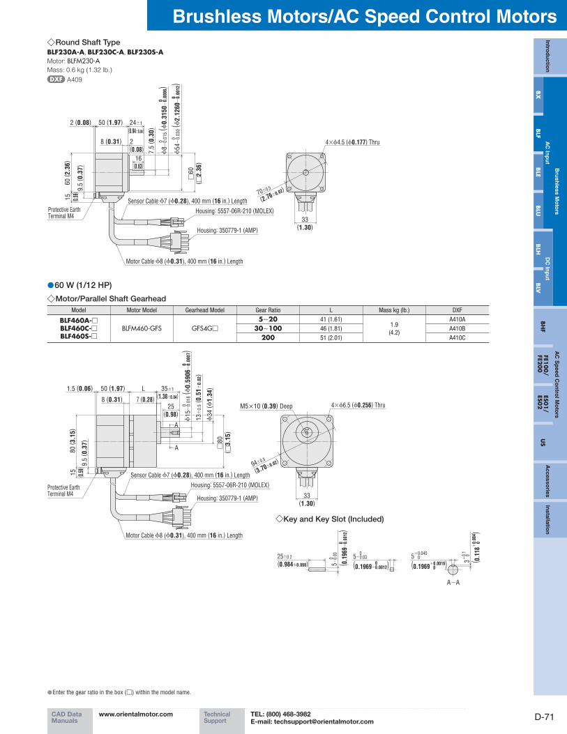
Round Shaft Type ◇BLF230A-A, BLF230C-A, BLF230S-AMotor: BLFM230-AMass: 0.6 kg (1.32 lb.)
A409
60
( 2.3
6)
15
( 0.5
9)9.5
( 0.3
7)
Protective EarthTerminal M4
2 (0.08) 50 (1.97) 24±1
(0.94±0.04)
8 (0.31) 2(0.08)
16(0.63)
7.5
( 0.3
0)
ϕ8
−0.0
15
( ϕ0.3
150
−0.0
006)
00
ϕ54
−0.0
30
( ϕ2.1
260
−0.0
012)
00
Housing: 5557-06R-210 (MOLEX)
Housing: 350779-1 (AMP)
Sensor Cable ϕ7 (ϕ0.28), 400 mm (16 in.) Length
Motor Cable ϕ8 (ϕ0.31), 400 mm (16 in.) Length
33(1.30)
70±0.5
(2.76±0.02)
4×ϕ4.5 (ϕ0.177) Thru
□60
( □2.3
6)
60 W (1/12 HP) ●Motor/Parallel Shaft Gearhead ◇
Model Motor Model Gearhead Model Gear Ratio L Mass kg (Ib.) DXF
BLF460A-□BLF460C-□BLF460S-□
BLFM460-GFS GFS4G□
5∼20 41 (1.61)1.9
(4.2)
A410A
30∼100 46 (1.81) A410B
200 51 (2.01) A410C
80
( 3.1
5)
15
( 0.5
9)
1.5 (0.06)
9.5
( 0.3
7)
50 (1.97) 35±1
(1.38±0.04)L
8 (0.31) 7 (0.28)25
(0.98)
Protective EarthTerminal M4
A
A
A−A
◇Key and Key Slot (Included)
Housing: 5557-06R-210 (MOLEX)
Housing: 350779-1 (AMP)
Sensor Cable ϕ7 (ϕ0.28), 400 mm (16 in.) Length
Motor Cable ϕ8 (ϕ0.31), 400 mm (16 in.) Length
13
±0
.5( 0
.51
±0
.02)
ϕ34
(ϕ1.3
4)
ϕ15
−0.0
18
( ϕ0.5
906
−0.0
007)
00 4×ϕ6.5 (ϕ0.256) Thru
33(1.30)
94±0.5
(3.70±0.02)
25±0.2
(0.984±0.008) 5−0.
03
( 0.1
969−
0.00
12)
0
0 5+0.040
(0.1969+0.0016)0
0
3+0.
1
( 0.1
18+
0.00
4 )0
05−0.03
(0.1969−0.0012)0
0
M5×10 (0.39) Deep
□80
( □3.1
5)

PageORIENTAL MOTOR GENERAL CATALOG 2012/2013
D-72
Brushless Motors/BLF Series
Features D-60 / System Configuration D-62 / Product Line D-63 / Specifications D-64 / Characteristics D-65Dimensions D-70 / Connection and Operation D-77 / Motor and Driver Combinations D-83
Motor/Hollow Shaft Flat Gearhead ◇BLF460A-□FR, BLF460C-□FR, BLF460S-□FRMotor: BLFM460-GFSGearhead: GFS4G□FRMass: 2.5 kg (5.5 lb.) (Including gearhead)
A411
A
A
A−A
◇Key (Included)
79.5
( 3.1
3)
9.5 (0.37)
Housing: 5557-06R-210 (MOLEX)
Housing: 350779-1 (AMP)
Sensor Cable ϕ7 (ϕ0.28), 400 mm (16 in.) Length
Motor Cable ϕ8 (ϕ0.31), 400 mm (16 in.) Length
Protective Earth Terminal M4
4 (0.16)
3 (0.12)
53.2(2.09)1 (0.04)
80
( 3.1
5) 8
0.5
( 3.1
7)
1.5 (0.06)8 (0.31)
45.2(1.78)
50 (1.97)
ϕ25
(ϕ0.
98)
ϕ38
−0.0
39
( ϕ1.4
961
−0.0
015)
0
0
5+0.040
(0.1969+0.0016)0
0
80 (3.15) 4×ϕ6.5 (ϕ0.256) Thru
17.3
( 0.6
8)
33
( 1.3
0)
160.5
( 6.3
2)8
0( 3
.15)
15 (0.59)
94±0.5
(3.70±0.02)
25±0.2
(0.984±0.008) 5−0.
03
( 0.1
969−
0.00
12)
0
0
5−0.03
(0.1969−0.0012)0
0
18 (0.71)
55.2 (2.17)
10 (0.39)
1.15 (0.05)
18 (0.71)
10 (0.39)
1.15 (0.05)
ϕ15
+0.
027
( ϕ0.
5906
+0.
0011
)0
0
ϕ15
+0.
027
( ϕ0.
5906
+0.
0011
)0
0
ϕ15
.7+
0.11
( ϕ0.
6181
+0.
0043
)0
0
ϕ15
.7+
0.11
( ϕ0.
6181
+0.
0043
)0
0
Round Shaft Type ◇BLF460A-A, BLF460C-A, BLF460S-AMotor: BLFM460-AMass: 0.9 kg (2.0 lb.)
A412
80
( 3.1
5)
15
( 0.5
9)9.5
( 0.3
7)
Protective EarthTerminal M4
1.5 (0.06) 50 (1.97) 32±1
(1.26±0.04)
8 (0.31) 2(0.08)
25(0.98)
9.5
( 0.3
7)
ϕ10
−0.0
15
( ϕ0.3
937
−0.0
006)
00
ϕ73
−0.0
30
( ϕ2.8
740
−0.0
012)
00
Housing: 5557-06R-210 (MOLEX)
Housing: 350779-1 (AMP)
Sensor Cable ϕ7 (ϕ0.28), 400 mm (16 in.) Length
Motor Cable ϕ8 (ϕ0.31), 400 mm (16 in.) Length
4×ϕ6.5 (ϕ0.256) Thru
33(1.30)
94±0.5
(3.70±0.02)
□80
( □3.1
5)
Enter the gear ratio in the box ( ● □) within the model name.
D-73
Brushless Motors/AC Speed Control MotorsIn
trod
uctio
n
Bru
shless M
oto
rsA
C S
peed
Co
ntro
l Mo
tors
Accesso
riesIn
stallation
AC
Inp
ut
DC
Inp
ut
BH
FFE1
00/
FE200
ES01/
ES02
US
BX
BLF
BLE
BLU
BLH
BLV
CAD DataManuals
www.orientalmotor.com Technical Support
TEL: (800) 468-3982E-mail: [email protected]
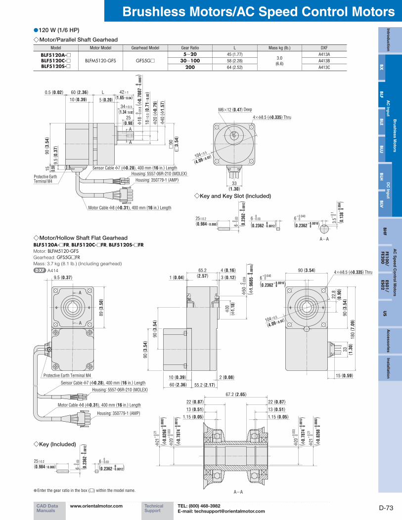
120 W (1/6 HP) ●Motor/Parallel Shaft Gearhead ◇
Model Motor Model Gearhead Model Gear Ratio L Mass kg (Ib.) DXF
BLF5120A-□BLF5120C-□BLF5120S-□
BLFM5120-GFS GFS5G□
5∼20 45 (1.77)3.0
(6.6)
A413A
30∼100 58 (2.28) A413B
200 64 (2.52) A413C
A
A
9.5
( 0.3
7)
15
( 0.5
9)
33(1.30)
90
( 3.5
4)
10 (0.39)
25(0.98)
5 (0.20)
0.5 (0.02) 60 (2.36) 42±1
(1.65±0.04)
34±0.5
(1.34±0.02)
L
ϕ40
(ϕ1.5
7)
ϕ20
(ϕ0.7
9)
Sensor Cable ϕ7 (ϕ0.28), 400 mm (16 in.) Length
Motor Cable ϕ8 (ϕ0.31), 400 mm (16 in.) Length
Housing: 5557-06R-210 (MOLEX)
Housing: 350779-1 (AMP)
104±0.5
(4.09±0.02)
4×ϕ8.5 (ϕ0.335) Thru
Protective EarthTerminal M4
M6×12 (0.47) Deep
ϕ18
−0.0
18
( ϕ0.7
087
−0.0
007)
00
18
±0
.5( 0
.71
±0
.02)
□90
( □3.5
4)
A−A
◇Key and Key Slot (Included)
25±0.2
(0.984±0.008) 6−0.
03
( 0.2
362−
0.00
12)
0
0
6−0.03
(0.2362−0.0012)0
06
+0.040
(0.2362+0.0016)0
0
3.5+
0.1
( 0.1
38+
0.00
4 )0
0
Motor/Hollow Shaft Flat Gearhead ◇BLF5120A-□FR, BLF5120C-□FR, BLF5120S-□FRMotor: BLFM5120-GFSGearhead: GFS5G□FRMass: 3.7 kg (8.1 lb.) (Including gearhead)
A414
A
A
◇Key (Included)
A−A
89
( 3.5
0)
9.5 (0.37)
Housing: 5557-06R-210 (MOLEX)
Housing: 350779-1 (AMP)
Sensor Cable ϕ7 (ϕ0.28), 400 mm (16 in.) Length
Motor Cable ϕ8 (ϕ0.31), 400 mm (16 in.) Length
Protective Earth Terminal M4
4 (0.16)
3 (0.12)
65.2(2.57)1 (0.04)
90
( 3.5
4)
90
( 3.5
4)
ϕ30
(ϕ1.
18)
ϕ50
−0.0
39
( ϕ1.9
685
−0.0
015)
0
0
2 (0.08)10 (0.39)
55.2 (2.17)60 (2.36)
6+0.040
(0.2362+0.0016)0
0
90 (3.54) 4×ϕ8.5 (ϕ0.335) Thru
104±0.5
(4.09±0.02)
22.8
( 0.9
0)
33
( 1.3
0)
180
( 7.0
9)
90
( 3.5
4)
15 (0.59)
25±0.2
(0.984±0.008) 6−0.
03
( 0.2
362−
0.00
12)
0
0
6−0.03
(0.2362−0.0012)0
0
22 (0.87) 22 (0.87)
67.2 (2.65)
13 (0.51) 13 (0.51)
1.15 (0.05) 1.15 (0.05)
ϕ20
+0.
033
( ϕ0.
7874
+0.
0013
)0
0
ϕ20
+0.
033
( ϕ0.
7874
+0.
0013
)0
0
ϕ21
+0.
21
( ϕ0.
8268
+0.
0083
)0
0
ϕ21
+0.
21
( ϕ0.
8268
+0.
0083
)0
0
Enter the gear ratio in the box ( ● □) within the model name.
PageORIENTAL MOTOR GENERAL CATALOG 2012/2013
D-74
Brushless Motors/BLF Series
Features D-60 / System Configuration D-62 / Product Line D-63 / Specifications D-64 / Characteristics D-65Dimensions D-70 / Connection and Operation D-77 / Motor and Driver Combinations D-83
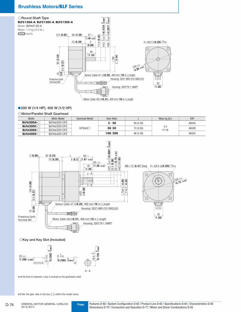
Round Shaft Type ◇BLF5120A-A, BLF5120C-A, BLF5120S-AMotor: BLFM5120-AMass: 1.5 kg (3.3 lb.)
A415
200 W (1/4 HP), 400 W (1/2 HP) ●Motor/Parallel Shaft Gearhead ◇
Model Motor Model Gearhead Model Gear Ratio L Mass kg (Ib.) DXF
BLF6200A-□ BLFM6200-GFS
GFS6G□
5∼20 60 (2.36)
5.4
(11.9)
A652ABLF6200C-□ BLFM6200-GFS
30, 50 72 (2.83) A652BBLF6200S-□ BLFM6200-GFS
100, 200 86 (3.39) A652CBLF6400S-□ BLFM6400-GFS
10 (0.39)
A
A
32(1.26) 2
4.5
( 0.9
6)5 (0.2) (1.97±0.04)
L2 (0.08)
104
( 4.0
9)
33(1.30)
82 (3.23) 50±1
35±0.5
(1.38±0.02)
ϕ22
−0.0
21
( ϕ0.8
661
−0
.00
08)
00
20
±0
.5( 0
.79
±0
.02)
ϕ42
(ϕ1.6
5)
ϕ25
(ϕ0.9
8)
□104
( □4.0
9)
□110
( □4.3
3)
Sensor Cable ϕ7 (ϕ0.28), 400 mm (16 in.) Length
Housing: 5557-06R-210 (MOLEX)
Housing: 350779-1 (AMP)
Motor Cable ϕ8 (ϕ0.31), 400 mm (16 in.) LengthProtective EarthTerminal M4
◇Key and Key Slot (Included)
9.5
( 0.3
7)
15
( 0.5
9)
M6×12 (0.47) Deep 4×ϕ8.5 (ϕ0.335) Thru
120±0.5
(4.72±0.02)
32±0.2
(1.260±0.008)
6−
0.0
3 0
( 0.2
362
−0
.00
12)
0
6−0.03 0
(0.2362−0.0012)0 18.5
−0.1
0
( 0.7
28
−0
.00
4)
0
A−A
90
( 3.5
4)
15
( 0.5
9)9.5
( 0.3
7)
Protective EarthTerminal M4
0.5 (0.02) 60 (2.36) 37±1
(1.46±0.04)
10 (0.39) 2(0.08)
30(1.18)
11.5
( 0.4
5)
ϕ12
−0.0
18
( ϕ0.4
724
−0.0
007)
00
ϕ83
−0.0
35
( ϕ3.2
677
−0.0
014)
00
Housing: 5557-06R-210 (MOLEX)
Housing: 350779-1 (AMP)
Sensor Cable ϕ7 (ϕ0.28), 400 mm (16 in.) Length
Motor Cable ϕ8 (ϕ0.31), 400 mm (16 in.) Length
4×ϕ8.5 (ϕ0.335) Thru
□90
( □3.5
4)
33(1.30)
104±0.5
(4.09±0.02)
At the time of shipment, a key is inserted on the gearhead’s shaft. ●
Enter the gear ratio in the box ( ● □) within the model name.

D-75
Brushless Motors/AC Speed Control MotorsIn
trod
uctio
n
Bru
shless M
oto
rsA
C S
peed
Co
ntro
l Mo
tors
Accesso
riesIn
stallation
AC
Inp
ut
DC
Inp
ut
BH
FFE1
00/
FE200
ES01/
ES02
US
BX
BLF
BLE
BLU
BLH
BLV
CAD DataManuals
www.orientalmotor.com Technical Support
TEL: (800) 468-3982E-mail: [email protected]
Enter the gear ratio in the box ( ● □) within the model name.
Motor/Hollow Shaft Flat Gearhead ◇Model Motor Model Gearhead Model Mass kg (Ib.) DXF
BLF6200A-□FRBLF6200C-□FRBLF6200S-□FR
BLFM6200-GFSGFS6G□FR 7.2
(15.8)A1146
BLF6400S-□FR BLFM6400-GFS
Protective Earth Terminal M4
Housing: 5557-06R-210(MOLEX)
Housing: 350779-1(AMP)
Motor Cable ϕ8 (ϕ0.31), 400 mm (16 in.) Length
Sensor Cable ϕ7 (ϕ0.28), 400 mm (16 in.) Length
◇Key (Included)
4×ϕ8.5 (ϕ0.335) Thru
A
A
2 (0.08)9.5 (0.37)
ϕ120±0.5
82 (3.23)
38
33
( 1.3
0)
15 (0.59)
8 0
−0.0
36
7 0
−0.0930±0.2
(1.181±0.008) ( 0.3
150
−0.0
014)
0
(0.2756−0.0035)0
A−A
10 (0.39)
67 (2.64) 5 (0.20)
104
( 4.0
9)
114
( 4.4
9)
1 (0.04)83.5 (3.29)
5 (0.20)7 (0.276) 104 (4.09)
8+0.040
0 (0.3150 0 )+0.0016
104
( 4.0
9)
218
( 8.5
8)
28.3
( 1.1
1)
(ϕ4.72±0.02)ϕ40
(ϕ1.5
7)
ϕ58
0−
0.0
46 (
ϕ2.2
835
−0.0
018)
0
(1.50)
89.5 (3.52)
1.35(0.05)
15 (0.59)30 (1.18)
1.35(0.05)
15 (0.59)30 (1.18)
ϕ
26.2
+0.2
1
( ϕ1.0
315
+0.0
083)
0 0
ϕ25
+0.0
33
( ϕ0.9
843
+0.0
013)
0
0
ϕ25
+0.0
33
( ϕ0.9
843
+0.0
013)
0
0
ϕ
26.2
+0.2
1
( ϕ1.0
315
+0.0
083)
0 0

PageORIENTAL MOTOR GENERAL CATALOG 2012/2013
D-76
Brushless Motors/BLF Series
Features D-60 / System Configuration D-62 / Product Line D-63 / Specifications D-64 / Characteristics D-65Dimensions D-70 / Connection and Operation D-77 / Motor and Driver Combinations D-83
Round Shaft Type ◇BLF6200A-A, BLF6200C-A, BLF6200S-A, BLF6400S-AMotor: BLFM6200-A, BLFM6400-AMass: 2.4 kg (5.3 lb.)
A653
2 (0.08)10 (0.39)2 (0.08)
30(1.18)
82 (3.23) 37±1 (1.46±0.04)
13
( 0.5
1)
ϕ14
−0.0
18
0
0( ϕ
0.5
512
−0
.00
07)
ϕ94
−0.0
35
0
0( ϕ
3.7
008
−0
.00
14)
□104
( □4.0
9)
4×ϕ8.5 (ϕ0.335) Thru
33(1.30)
120±0.5
(4.72±0.0
2)
Sensor Cable ϕ7 (ϕ0.28), 400 mm (16 in.) Length
Housing: 5557-06R-210 (MOLEX)
Housing: 350779-1 (AMP)
Motor Cable ϕ8 (ϕ0.31), 400 mm (16 in.) Length
104
( 4.0
9)
9.5
( 0.3
7)
15
( 0.5
9)
Protective EarthTerminal M4
Driver ◇BLFD30A2, BLFD30C2, BLFD30S2BLFD60A2, BLFD60C2, BLFD60S2BLFD120A2, BLFD120C2, BLFD120S2Mass: 0.9 kg (2.0 lb.)
A416
Slits
85 (3.35)5 (0.20)
106
( 4.1
7)
95 (3.74)
130
( 5.1
2)
84 (3.31)
2×ϕ4.5 (ϕ0.177) Thru
Protective Earth Terminal M4
Protective Earth Terminal M4
19( 0
.75)
5 (0.20)
Digital Operator ◇(Detached from the driver)
10.8(0.43)
17(0.67)
12.8
( 0.5
0)
7( 0
.28)
34
( 1.3
4)
69(2.72)
85 (3.35)
50
( 1.9
7)
17( 0
.67)
max
.
13.4
( 0.5
3)
4×M3×4 (0.16) Deep
BLFD200A2, BLFD200C2, BLFD200S2,
BLFD400S2Mass: 1.3 kg (2.9 lb.)
A654
Slits
95 (3.74)
110 (4.33)85 (3.35)
106
( 4.1
7)
130
( 5.1
2)
5 (0.20)2×ϕ4.5 (ϕ0.177) Thru
Protective Earth Terminal M4
Protective Earth Terminal M4
19( 0
.75)
5 (0.20)
Digital Operator Panel Cut-Out ◇
69±0.1 (2.717±0.004)
4×R2 (R0.079)
max.
9.8±0.2
(0.386±0.008)19
(0.75)
12.3
±0.
2
( 0.4
8±0.
008)
8±
0.2
( 0.3
15
±0.0
08)
34
±0.1
( 1.3
39
±0.0
04)
4×ϕ3.5 (ϕ0.138)

D-77
Brushless Motors/AC Speed Control MotorsIn
trod
uctio
n
Bru
shless M
oto
rsA
C S
peed
Co
ntro
l Mo
tors
Accesso
riesIn
stallation
AC
Inp
ut
DC
Inp
ut
BH
FFE1
00/
FE200
ES01/
ES02
US
BX
BLF
BLE
BLU
BLH
BLV
CAD DataManuals
www.orientalmotor.com Technical Support
TEL: (800) 468-3982E-mail: [email protected]
Connection and Operation ■
Names and Functions of Driver Parts ●
Digital Operator
Protective
Earth
Terminal
Input/Output
Signal
Connection
Terminals
Power Supply Connection
Terminals
Motor Connection
Terminals
Internal Speed
Potentiometer
Signal Cable
Connection Terminals
Protective
Earth Terminal
Digital Operator ◇
POWER LED
External Voltage Select Switch
Remote-Control Connector CN2
When the digital operator is detached
Sink/Source-Input
Select Switch
Digital Operator Connector CN1
Use this switch to select
the sink mode or source
mode for the input circuit.
To set speeds using external DC voltage, set this switch
to 5 V or 10 V in accordance with the voltage supply used.
To use the digital operator remotely from
the driver, connect the cable of the
remote-control kit (sold separately) to
this connector.
RUN LED
ALARM LED
Mode Indicator LEDs Unit Indicator LEDs
RUN Key
STOP Key
Operation Keys
Input/Output Signals ●Terminal Name Signal Signal Name Function
TH
Input
N. C. Do not connect any signals to this terminal.
TH N. C. Do not connect any signals to this terminal.
M0 M0 InputThese signals are used to select operation data in multi-speed operation.
One of up to eight preset speed data can be selected using the M0, M1 and M2 inputs.M1 M1 Input
M2 M2 Input
VH VH Input
These signals are used to set speeds via an external speed potentiometer or external DC voltage.VM VM Input
VL VL Input
C3 IN-COM1 Input signal common (0 V)
X0✽1 EXT-ERROR Input External error input (Normally closed)
C0 IN-COM0 Input signal common
C1 IN-COM0 Input signal common
X1✽22-Wire Mode: CW Input Clockwise rotation/stop switch input signal
3-Wire Mode: START/STOP Input Start/stop input signal
X2✽22-Wire Mode: CCW Input Counterclockwise rotation/stop switch input signal
3-Wire Mode: RUN/BRAKE Input Run/instantaneous stop input signal
X3✽22-Wire Mode: STOP-MODE Input This signal is input to select the motor stop action.
3-Wire Mode: CW/CCW Input Clockwise/counterclockwise direction input signal
X4 N. C. Do not connect any signals to this terminal.
X5 ALARM-RESET Input This signal is used to reset alarms.
Y1
Output
ALARM-OUT1 Output This signal is output upon generation of an alarm. (Normally closed)
Y2 ALARM-OUT2 Output This signal is output upon actuation of the overload protective function or overload warning function. (Normally closed)
Y0 SPEED-OUT Output 30 pulses are output per each rotation of the motor output shaft.
C2 OUT-COM Output signal common
1 Do not remove the short circuit bar if the EXT-ERROR input is not used. ✽
2 The functions of the external-input signal terminals X1, X2 and X3 can be changed between the 2-wire input mode and 3-wire input mode. The functions under the 2-wire input mode are initially ✽
assigned to the terminals.
Digital Operator Indicator ●Display Function Description
RUN Running A green LED stays lit while the motor is running.
ALARM Alarm A red LED turns on when an alarm occurs.
Mode
MNTR Monitor mode The motor can be operated in this mode. The motor speed and load condition are displayed during motor operation.
F/R Direction setting modeIf the digital operator is used to operate the motor, set the motor direction in this mode.
For: Clockwise direction, rEv: Counterclockwise direction
LO/REDigital operator/external-input
signal mode
In this mode, set whether to use the digital operator or external I/O signals to input the motor operation/stop signals.
Lo: Digital operator, rE: External-input signals
PRGM Data setting mode
In this mode, set the data needed to operate the motor.
Operation data (eight speeds and acceleration/deceleration times), Gear ratio setting/conveyor speed setting
Input mode, Overload warning function
Display Unit
r/min Motor speed The speed of the motor or gearhead output shaft is displayed.
m/min Conveyor speed An equivalent moving speed of the work on a conveyor or other transfer system is displayed.
% Load factor✽ The actual load is displayed as a percentage of the rated torque being 100%.
A maximum error of approximately 20% may generate when the motor is operated at the rated speed under the rated load. ✽
PageORIENTAL MOTOR GENERAL CATALOG 2012/2013
D-78
Brushless Motors/BLF Series
Features D-60 / System Configuration D-62 / Product Line D-63 / Specifications D-64 / Characteristics D-65Dimensions D-70 / Connection and Operation D-77 / Motor and Driver Combinations D-83
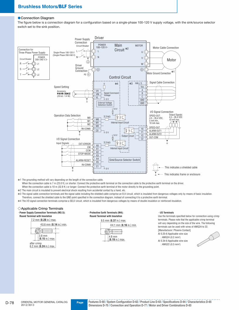
Connection Diagram ●The figure below is a connection diagram for a configuration based on a single-phase 100-120 V supply voltage, with the sink/source selector
switch set to the sink position.
Driver
Main
Circuit ✽2 Motor Cable Connection
Motor
Power Supply
ConnectionCircuit Breaker
DriverGroundConnection
PE
MOTORPOWER100–120 V~
Control CircuitMotor Ground Connection
✽1
U
V
W
Speed Setting
AccessoryPAVR-20KZ(20 kΩ 1/4 W)
Operation Data Selection
I/O Signal Connection
Signal Cable Connection
I/O Signal Connection
Sink/Source Selector Switch
Speed CommandVoltage
External VoltageSelection Switch
0 V
0 V
0 V
✽4 ✽3
VH
VM
VL
M0
M1
M2
IN-COM0
M0
M1
M2
C0
Input Signals EXT-ERROR
CW
CCW
STOP-MODE
ALARM-RESET
IN-COM0
X0
X1
X2
X3
X4
X5
C1
3.3 kΩ
3.3 kΩ
+14 V
+14 V
Internal Input Circuit
Internal Input Circuit
Output Circuit
Y0
Y1
Y2
C2
HALL S.
Vcc
A
B
C
GND
GND
SPEED-OUT
ALARM-OUT1
ALARM-OUT2
OUT-COM
SPEED-OUT:4.5 ~ 26.4 VDC,5 mA min.,10 mA max.
Output Signals:4.5 ~ 26.4 VDC10 mA max.
This indicates a shielded cable
This indicates frame or enclosure
L
N
L
N
Single-Phase 100-120 V
(Single-Phase 200-240 V)
1 The grounding method will vary depending on the length of the connection cable. ✽
When the connection cable is 7 m (23.0 ft.) or shorter: Connect the protective earth terminal on the connection cable to the protective earth terminal on the driver.
When the connection cable is 10 m (32.8 ft.) or longer: Connect the protective earth terminal of the motor directly to the grounding point.
2 The main circuit is insulated to prevent electrical shock resulting from accidental contact by a hand, etc. ✽
3 The signal cable connection terminals and the signal cable including the shielded cable comprise an ELV circuit, which is insulated from dangerous voltages only by means of basic insulation. ✽
Therefore, connect the shielded cable to the GND point specified in the connection diagram, instead of connecting it to a protective earth terminal.
4 The I/O signal connection terminals comprise a SELV circuit, which is insulated from dangerous voltages by means of double insulation or reinforced insulation. ✽
Applicable Crimp Terminals ◇· Power Supply Connection Terminals (M3.5):
Round Terminal with Insulation
ϕ3.6 mm (0.14 in.) min.
3.8 mm(0.15 in.) max.
7.2 mm (0.28 in.) max.
after crimp6.2 mm (0.24 in.) max.
· Protective Earth Terminals (M4):
Round Terminal with Insulation
ϕ4.1 mm (0.16 in.) min.
4.8 mm(0.19 in.) max.
9.5 mm (0.37 in.) max.
· I/O Terminals
Use the terminals specified below for connection using crimp
terminals. Please note that the applicable crimp terminal
will vary depending on the size of the wire. The following
terminals can be used with wires of AWG24 to 22.
[Manufacturer: Phoenix Contact]
AI 0.25-6 Applicable wire size
: AWG24 (0.2 mm2)
AI 0.34-6 Applicable wire size
: AWG22 (0.3 mm2)
Connection for
Three-Phase Power Supply
Circuit BreakerPOWER
200–240 V 3~
R
S
T
L1
L2
L3
D-79
Brushless Motors/AC Speed Control MotorsIn
trod
uctio
n
Bru
shless M
oto
rsA
C S
peed
Co
ntro
l Mo
tors
Accesso
riesIn
stallation
AC
Inp
ut
DC
Inp
ut
BH
FFE1
00/
FE200
ES01/
ES02
US
BX
BLF
BLE
BLU
BLH
BLV
CAD DataManuals
www.orientalmotor.com Technical Support
TEL: (800) 468-3982E-mail: [email protected]
Timing Chart ●2-Wire Mode ◇
10 ms min.
10 ms min. 10 ms min.
Motor
Operation
Pattern CCW
CW CW CW
CCW
10 ms min.
CW ON ONOFF
ON
CCW
STOP-
MODE
ON ONONON
OFF
ONON
OFF
Bi-Directional Operation
Instantaneous Stop
Deceleration Stop
Rotation Direction Switching/Stop Method Selection
Instantaneous
Stop Instantaneous
Stop
Deceleration Stop
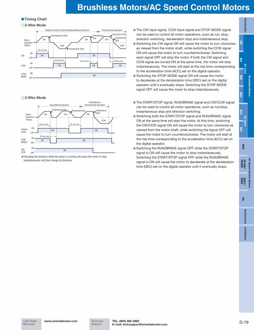
The CW input signal, CCW input signal and STOP-MODE signal ●can be used to control all motor operations, such as run, stop,
direction switching, deceleration stop and instantaneous stop.
Switching the CW signal ON will cause the motor to turn clockwise ●as viewed from the motor shaft, while switching the CCW signal
ON will cause the motor to turn counterclockwise. Switching
each signal OFF will stop the motor. If both the CW signal and
CCW signal are turned ON at the same time, the motor will stop
instantaneously. The motor will start at the rise time corresponding
to the acceleration time (ACC) set on the digital operator.
Switching the STOP-MODE signal ON will cause the motor ●to decelerate at the deceleration time (DEC) set on the digital
operator until it eventually stops. Switching the STOP-MODE
signal OFF will cause the motor to stop instantaneously.
3-Wire Mode ◇
10 ms min. 10 ms min.
10 ms min.
Motor
Operation
Pattern
CW CWCW
CCW
START/
STOPON ON
OFF
ON
RUN/
BRAKEONON
ON
OFF
CW/
CCWON
ON
OFF
Instantaneous
Bi-Directional Operation
Instantaneous Stop
Stop Method Selection
Instantaneous
Stop✽Deceleration Stop
Changing the direction while the motor is running will cause the motor to stop ✽
instantaneously and then change its direction.
The START/STOP signal, RUN/BRAKE signal and CW/CCW signal ●can be used to control all motor operations, such as run/stop,
instantaneous stop and direction switching.
Switching both the START/STOP signal and RUN/BRAKE signal ●ON at the same time will start the motor. At this time, switching
the CW/CCW signal ON will cause the motor to turn clockwise as
viewed from the motor shaft, while switching the signal OFF will
cause the motor to turn counterclockwise. The motor will start at
the rise time corresponding to the acceleration time (ACC) set on
the digital operator.
Switching the RUN/BRAKE signal OFF while the START/STOP ●signal is ON will cause the motor to stop instantaneously.
Switching the START/STOP signal OFF while the RUN/BRAKE
signal is ON will cause the motor to decelerate at the deceleration
time (DEC) set on the digital operator until it eventually stops.
PageORIENTAL MOTOR GENERAL CATALOG 2012/2013
D-80
Brushless Motors/BLF Series
Features D-60 / System Configuration D-62 / Product Line D-63 / Specifications D-64 / Characteristics D-65Dimensions D-70 / Connection and Operation D-77 / Motor and Driver Combinations D-83
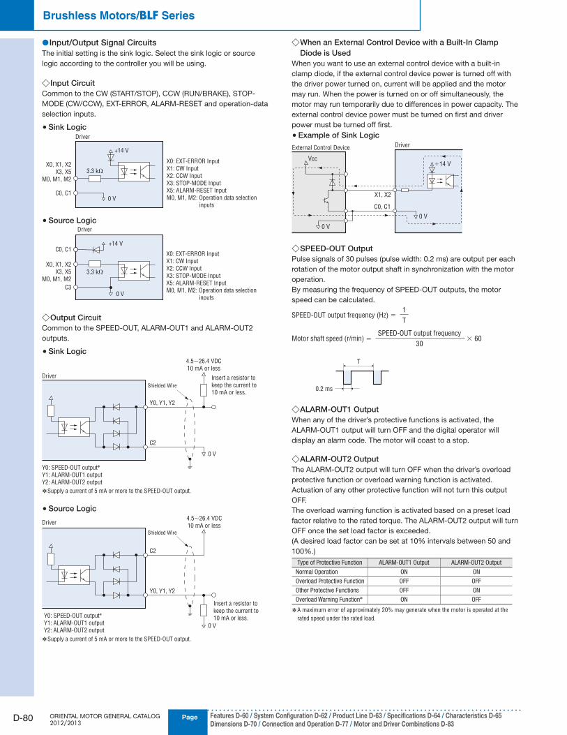
Input/Output Signal Circuits ●The initial setting is the sink logic. Select the sink logic or source
logic according to the controller you will be using.
Input Circuit ◇Common to the CW (START/STOP), CCW (RUN/BRAKE), STOP-
MODE (CW/CCW), EXT-ERROR, ALARM-RESET and operation-data
selection inputs.
Sink Logic ●Driver
X0, X1, X2
X3, X5
M0, M1, M2
X0: EXT-ERROR Input
X1: CW Input
X2: CCW Input
X3: STOP-MODE Input
X5: ALARM-RESET Input
M0, M1, M2: Operation data selection
inputs
C0, C1
3.3 kΩ
+14 V
0 V
Source Logic ●
X0, X1, X2
X3, X5
M0, M1, M2
C0, C1
C3
3.3 kΩ
+14 V
0 V
Driver
X0: EXT-ERROR Input
X1: CW Input
X2: CCW Input
X3: STOP-MODE Input
X5: ALARM-RESET Input
M0, M1, M2: Operation data selection
inputs
Output Circuit ◇Common to the SPEED-OUT, ALARM-OUT1 and ALARM-OUT2
outputs.
Sink Logic ●
Y0: SPEED-OUT output✽
Y1: ALARM-OUT1 output
Y2: ALARM-OUT2 output
C2
4.5∼26.4 VDC
10 mA or less
0 V
Y0, Y1, Y2
Driver
Shielded Wire
Insert a resistor to
keep the current to
10 mA or less.
Supply a current of 5 mA or more to the SPEED-OUT output. ✽
Source Logic ●
C2
0 V
Y0, Y1, Y2
Shielded Wire
Y0: SPEED-OUT output✽
Y1: ALARM-OUT1 output
Y2: ALARM-OUT2 output
4.5∼26.4 VDC
10 mA or lessDriver
Insert a resistor to
keep the current to
10 mA or less.
Supply a current of 5 mA or more to the SPEED-OUT output. ✽
When an External Control Device with a Built-In Clamp ◇Diode is Used
When you want to use an external control device with a built-in
clamp diode, if the external control device power is turned off with
the driver power turned on, current will be applied and the motor
may run. When the power is turned on or off simultaneously, the
motor may run temporarily due to differences in power capacity. The
external control device power must be turned on first and driver
power must be turned off first.
Example of Sink Logic ●External Control Device Driver
X1, X2
C0, C1
Vcc+14 V
0 V
0 V
SPEED-OUT Output ◇Pulse signals of 30 pulses (pulse width: 0.2 ms) are output per each
rotation of the motor output shaft in synchronization with the motor
operation.
By measuring the frequency of SPEED-OUT outputs, the motor
speed can be calculated.
Motor shaft speed (r/min) = × 60SPEED-OUT output frequency
30
SPEED-OUT output frequency (Hz) =1
T
0.2 ms
T
ALARM-OUT1 Output ◇When any of the driver’s protective functions is activated, the
ALARM-OUT1 output will turn OFF and the digital operator will
display an alarm code. The motor will coast to a stop.
ALARM-OUT2 Output ◇The ALARM-OUT2 output will turn OFF when the driver’s overload
protective function or overload warning function is activated.
Actuation of any other protective function will not turn this output
OFF.
The overload warning function is activated based on a preset load
factor relative to the rated torque. The ALARM-OUT2 output will turn
OFF once the set load factor is exceeded.
(A desired load factor can be set at 10% intervals between 50 and
100%.)
Type of Protective Function ALARM-OUT1 Output ALARM-OUT2 Output
Normal Operation ON ON
Overload Protective Function OFF OFF
Other Protective Functions OFF ON
Overload Warning Function✽ ON OFF
A maximum error of approximately 20% may generate when the motor is operated at the ✽
rated speed under the rated load.

D-81
Brushless Motors/AC Speed Control MotorsIn
trod
uctio
n
Bru
shless M
oto
rsA
C S
peed
Co
ntro
l Mo
tors
Accesso
riesIn
stallation
AC
Inp
ut
DC
Inp
ut
BH
FFE1
00/
FE200
ES01/
ES02
US
BX
BLF
BLE
BLU
BLH
BLV
CAD DataManuals
www.orientalmotor.com Technical Support
TEL: (800) 468-3982E-mail: [email protected]
Operating Methods ●
or
① Set speeds using
the internal
speed potentiometer
④ Set speeds using
external DC voltage
③ Set speeds using
the external
speed potentiometer
b) Operate the motor
using the external
input signals
② Set speeds using
the digital operatora) Operate the motor
using the digital
operator
One of the following two operating methods (a and b) can be set
by switching between the digital operator mode and external input
signal mode.
a) Operate the motor using the RUN and STOP keys on the digital
operator
b) Operate the motor using external input signals
Speed Setting Methods ●One of the following four methods (① to ④) can be used to set
speeds:
① Set speeds using the internal speed potentiometer
Set speeds using the potentiometer provided on the driver’s front
panel.
② Set speeds using the digital operator
The digital operator can be used to set speeds in units of 1 r/min.
Up to eight speed data can be set.
③ Set speeds using an external speed potentiometer
(sold separately)
To set speeds at a location away from the driver, connect an
accessory external speed potentiometer as shown below.
External Speed Potentiometer
PAVR-20KZ
Shielded Wire
3: To VH Input
2: To VM Input
1: To VL Input
1000
2000
3000
4000
0 20 40 60 80 100
Scale Plate Value
External Speed Potentiometer Scale – Speed Characteristics(Representative values)
Spee
d[ r
/min
]
Note
The speed in the graph represents the speed of a motor alone. The gearhead output shaft ●speed of the combination type is calculated by dividing the graph speed by the gear ratio.
④ Set speeds using external DC voltage
Set the external voltage select switch on the driver in accordance
with the external DC voltage to be supplied. Detach the digital
operator and set the switch to either 5 V or 10 V.
Thereafter, connect an external DC power supply as shown
below. Connect the positive and negative terminals of the power
supply correctly.
+: To VM Input
−: To VL Input
10V 5V
Set the External Voltage
Selection Switch
External DC Power Supply
0 to 5 VDC or
0 to 10 VDC
1 mA or more
Shielded Wire
1000
2000
3000
4000
0 1 2 3 4 5 6 7 8 9 10
DC Voltage [VDC]
5 VDC
10 VDC
External DC Voltage – Speed Characteristics(Representative values)
Spee
d[ r
/min
]
Note
The speed in the graph represents the speed of a motor alone. The gearhead output shaft ●speed of the combination type is calculated by dividing the graph speed by the gear ratio.
Multi-Speed Operation ●Two-Speed Operation ◇
The speed set by the internal speed potentiometer and another set
by an external speed potentiometer can be combined for two-speed
operation by switching the operation data selection input M0.
M0 Input M1 Input M2 Input Speed Setting Method
OFF OFF OFF Internal speed potentiometer
ON OFF OFF External speed potentiometer
Internal Potentiometer Speed
External Potentiometer Speed
External Potentiometer Speed
Internal Speed Potentiometer External Speed PotentiometerOFF
ON
CW
CCW
2 s
OFF
ON
Internal/External Potentiometer Switching
Motor
Operation
Pattern
Power
Supply
Digital
Operator
Operation
M0 Input
Direction Change
Direction
Setting
Change

PageORIENTAL MOTOR GENERAL CATALOG 2012/2013
D-82
Brushless Motors/BLF Series
Features D-60 / System Configuration D-62 / Product Line D-63 / Specifications D-64 / Characteristics D-65Dimensions D-70 / Connection and Operation D-77 / Motor and Driver Combinations D-83
Eight-Speed Operation ◇A multi-speed operation using up to eight speeds can be performed
by setting desired speeds in operation data No. 1 to 8 and then
switching the speed using operation-data selection input M0, M1 or
M2.
Operation Data M0 Input M1 Input M2 Input Speed Setting Method
No. 1 OFF OFF OFF Internal speed potentiometer/Digital operator
No. 2 ON OFF OFF External speed potentiometer/Digital operator
No. 3 OFF ON OFF Digital operator
No. 4 ON ON OFF Digital operator
No. 5 OFF OFF ON Digital operator
No. 6 ON OFF ON Digital operator
No. 7 OFF ON ON Digital operator
No. 8 ON ON ON Digital operator
No.1
No.2
No.3
No.4
No.5
No.6
No.7
No.8
OFF
ONCW ON
ON
OFFM2 ON
ON
OFFM1 ON ON
ON
OFFON ON ON ONM0
CW
Motor
Operation
Pattern
Multi-Motor Control ●Two or more motors can be operated at the same speed by using a
single external speed potentiometer or external DC voltage.
The diagram below applies to a single-phase power supply
specification. For a three-phase power supply specification, change
the power supply line to a three-phase type. Also note that the
diagram does not show the motor or operation control part.
Using an External Speed Potentiometer ◇As shown in the diagram, use a common power supply line and a
common speed control line for each driver and set speeds by using
the external speed potentiometer VRx.
The resistance of the external speed potentiometer is determined
using the formula below:
Resistance when the number of drivers is n:
VRx = 20/n (kΩ), n/4 (W)
Example: When two drivers are connected
VRx = 20/2 = 10 (kΩ), 2/4 = 1/2 (W)
Accordingly, the resistance is calculated as 10 kΩ, 1/2 W.
To adjust the speed difference between motors, connect a 1.5 kΩ,
1/4 W resistor to the VM terminal on the first driver and connect a
5 kΩ, 1/4 W variable resistor (VRn) to the VM terminal on each of the
remaining drivers.
Up to five drivers can be operated in parallel using an external speed
potentiometer.
1.5 kΩ 1/4 WVRn
5 kΩ 1/4 W
1
3
2
Driver 1
VM VL
L N
VH VM VL
L N
VH
Speed Control LineExternal Speed
Potentiometer VRx
Power
Supply
Input Power Supply Line
Driver n
Using External DC Voltage ◇As shown in the diagram, use a common power supply line and a
common speed control line for each driver and connect all drivers to
a 5 or 10 VDC power supply.
The power-supply capacity of the external DC power supply is
determined using the formula below:
Power-supply capacity when the number of drivers is n:
I = 1 × n (mA)
Example: When two drivers are connected
I = 1 × 2 = 2 (mA)
Accordingly, the power-supply capacity is calculated as
2 mA or more.
To adjust the speed difference between motors, connect a 1.5 kΩ,
1/4 W resistor to the VM terminal on the first driver, and connect a
5 kΩ, 1/4 W variable resistor (VRn) to the VM terminal on each of the
remaining drivers.
1.5 kΩ 1/4 WVRn
5 kΩ 1/4 W
Speed Control Line
Driver 1
VM VL
L N
Driver n
VM VL
L NPower
Supply
InputPower Supply Line
External DC Power Supply
0 to 5 VDC or
0 to 10 VDC
Using the Digital Operator ◇When multiple drivers are connected and the same data is set
digitally where the same data are set digitally in each driver, the
operations of multiple motors can be controlled via an external input
signal using the wiring circuit shown below.
Power
Supply
InputPower Supply Line
Driver 1
X1 X2
L N
C1
Driver n
X1 X2
L N
C1
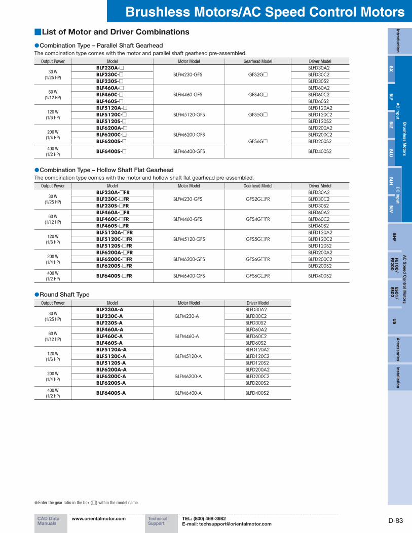
D-83
Brushless Motors/AC Speed Control MotorsIn
trod
uctio
n
Bru
shless M
oto
rsA
C S
peed
Co
ntro
l Mo
tors
Accesso
riesIn
stallation
AC
Inp
ut
DC
Inp
ut
BH
FFE1
00/
FE200
ES01/
ES02
US
BX
BLF
BLE
BLU
BLH
BLV
CAD DataManuals
www.orientalmotor.com Technical Support
TEL: (800) 468-3982E-mail: [email protected]
List of Motor and Driver Combinations ■
Combination Type – Parallel Shaft Gearhead ●The combination type comes with the motor and parallel shaft gearhead pre-assembled.
Output Power Model Motor Model Gearhead Model Driver Model
30 W
(1/25 HP)
BLF230A-□BLFM230-GFS GFS2G□
BLFD30A2BLF230C-□ BLFD30C2BLF230S-□ BLFD30S2
60 W
(1/12 HP)
BLF460A-□BLFM460-GFS GFS4G□
BLFD60A2BLF460C-□ BLFD60C2BLF460S-□ BLFD60S2
120 W
(1/6 HP)
BLF5120A-□BLFM5120-GFS GFS5G□
BLFD120A2BLF5120C-□ BLFD120C2BLF5120S-□ BLFD120S2
200 W
(1/4 HP)
BLF6200A-□BLFM6200-GFS
GFS6G□
BLFD200A2BLF6200C-□ BLFD200C2BLF6200S-□ BLFD200S2
400 W
(1/2 HP)BLF6400S-□ BLFM6400-GFS BLFD400S2
Combination Type – Hollow Shaft Flat Gearhead ●The combination type comes with the motor and hollow shaft flat gearhead pre-assembled.
Output Power Model Motor Model Gearhead Model Driver Model
30 W
(1/25 HP)
BLF230A-□FRBLFM230-GFS GFS2G□FR
BLFD30A2BLF230C-□FR BLFD30C2BLF230S-□FR BLFD30S2
60 W
(1/12 HP)
BLF460A-□FRBLFM460-GFS GFS4G□FR
BLFD60A2BLF460C-□FR BLFD60C2BLF460S-□FR BLFD60S2
120 W
(1/6 HP)
BLF5120A-□FRBLFM5120-GFS GFS5G□FR
BLFD120A2BLF5120C-□FR BLFD120C2BLF5120S-□FR BLFD120S2
200 W
(1/4 HP)
BLF6200A-□FRBLFM6200-GFS GFS6G□FR
BLFD200A2BLF6200C-□FR BLFD200C2BLF6200S-□FR BLFD200S2
400 W
(1/2 HP)BLF6400S-□FR BLFM6400-GFS GFS6G□FR BLFD400S2
Round Shaft Type ●Output Power Model Motor Model Driver Model
30 W
(1/25 HP)
BLF230A-ABLFM230-A
BLFD30A2BLF230C-A BLFD30C2BLF230S-A BLFD30S2
60 W
(1/12 HP)
BLF460A-ABLFM460-A
BLFD60A2BLF460C-A BLFD60C2BLF460S-A BLFD60S2
120 W
(1/6 HP)
BLF5120A-ABLFM5120-A
BLFD120A2BLF5120C-A BLFD120C2BLF5120S-A BLFD120S2
200 W
(1/4 HP)
BLF6200A-ABLFM6200-A
BLFD200A2BLF6200C-A BLFD200C2BLF6200S-A BLFD200S2
400 W
(1/2 HP)BLF6400S-A BLFM6400-A BLFD400S2
Enter the gear ratio in the box ( ● □) within the model name.