Embed Size (px)
Citation preview
1
Models MT 3809 & 3819
Data SheetDS-VA-MT3809-3819-engMarch, 2008
Brooks® Models MT 3809 and 3819Metal Tube Variable Area Flowmeterswith Optional Electronics based on Smart Meter ManagerTM
Technology
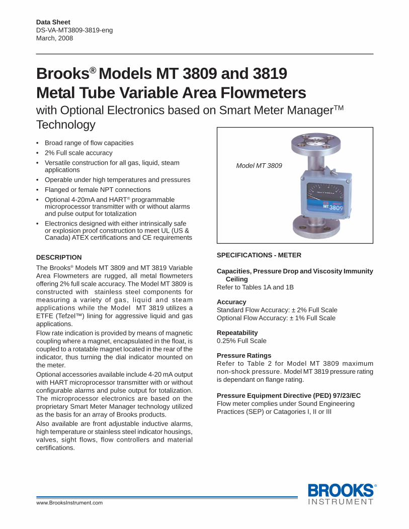
Model MT 3809
• Broad range of flow capacities• 2% Full scale accuracy• Versatile construction for all gas, liquid, steam
applications• Operable under high temperatures and pressures• Flanged or female NPT connections• Optional 4-20mA and HART® programmable
microprocessor transmitter with or without alarmsand pulse output for totalization
• Electronics designed with either intrinsically safeor explosion proof construction to meet UL (US &Canada) ATEX certifications and CE requirements
DESCRIPTIONThe Brooks® Models MT 3809 and MT 3819 VariableArea Flowmeters are rugged, all metal flowmetersoffering 2% full scale accuracy. The Model MT 3809 isconstructed with stainless steel components formeasuring a variety of gas, l iquid and steamapplications while the Model MT 3819 utilizes aETFE (Tefzel™) lining for aggressive liquid and gasapplications.Flow rate indication is provided by means of magneticcoupling where a magnet, encapsulated in the float, iscoupled to a rotatable magnet located in the rear of theindicator, thus turning the dial indicator mounted onthe meter.Optional accessories available include 4-20 mA outputwith HART microprocessor transmitter with or withoutconfigurable alarms and pulse output for totalization.The microprocessor electronics are based on theproprietary Smart Meter Manager technology utilizedas the basis for an array of Brooks products.Also available are front adjustable inductive alarms,high temperature or stainless steel indicator housings,valves, sight flows, flow controllers and materialcertifications.
SPECIFICATIONS - METER
Capacities, Pressure Drop and Viscosity ImmunityCeiling
Refer to Tables 1A and 1B
AccuracyStandard Flow Accuracy: ± 2% Full ScaleOptional Flow Accuracy: ± 1% Full Scale
Repeatability0.25% Full Scale
Pressure RatingsRefer to Table 2 for Model MT 3809 maximumnon-shock pressure. Model MT 3819 pressure ratingis dependant on flange rating.
Pressure Equipment Directive (PED) 97/23/ECFlow meter complies under Sound EngineeringPractices (SEP) or Catagories I, II or III
2
Models MT 3809 & 3819
Data SheetDS-VA-MT3809-3819-eng
March, 2008
ScalesStandard: Detachable aluminum plate (Single or dual
scales)Graduations: Choice of direct reading units, millimeters
or percentage of maximum flow
Operating Fluid Temperature Limits (Meter only)Minimum MT 3809 and MT 3819: -20°F (-29°C)Maximum:
Standard MT 3809: 420°F(215°C)Standard MT 3809 with Valve: 392°F(200°C)
Refer to Table 3 for temperature limitations for meterswith electronics.
Materials of Construction:Metering TubeMT 3809 Standard: 316L stainless steelMT 3809 Optional: Inconnel 625™, Hastelloy B™,
Hastelloy C™, titanium
MT 3819 Standard: 316L stainless steel with ETFE(Tefzel) lining
Flanges and End FittingsMT 3809 Standard: 316/316L stainless steel dualcertifiedMT 3809 Optional: Inconnel 625, Hastelloy C, titanium
MT 3819 Standard: 316L stainless steel
ConnectionsMT 3809 Standard:150 lbs, 300 lbs or 600 lbs RF ANSI B 16.5 flanges or
PN 40 DIN 2527/2635; or JIS flanges 10K or 20K;or Female NPT, Male NPT for No O-ring meter only
125/250 Ra micro inch (3.2/6.3 Ra micro meter) ceratedflange finish. Consult factory for optional unceratedflange finish.
Vertical inlet and outlet
MT 3819 Standard:150 lbs RF ANSI B 16.5 flanges or PN 40 DIN 2527/
2635MT 3819 Optional:300 lbs RF ANSI B 16.5 flanges or PN 40 DIN 2527/
2635. For other ratings/flange types consult factory.125/250 Ra micro inch (3.2/6.3 Ra micro meter) cerated
flange finish. Consult factory for optional unceratedflange finish.
Vertical inlet and outlet
FloatsMT 3809 Standard: 316L stainless steelMT 3809 Optional: Inconnel 625, Hastelloy C, titanium
MT 3819 Standard: Hastelloy C, Sizes 7 and 8, PVDFSizes 10, 12 and 13.
MT 3819 Optional: Inconnel 625 or titanium all sizes;all Teflon® internals Sizes 10, 12 and 13.
O-rings (NPT only)MT 3809 Standard: Viton® fluoroelastomersMT 3809 Optional: Teflon®, none with male NPT
connections
MT 3819: None
Indicator Housing and CoverEnclosure NEMA 4X constructionMT 3809 and MT 3819 Standard Housing: Die cast
aluminum, polyurethane paint with glass windowMT 3809 and MT 3819 Optional Housing: 316L
stainless steel with gritblast and glass window; epoxypaint for aluminum housing
Meter DimensionsRefer to Figure 1Ordering Information and Model CodeRefer to Table 4
OPTIONAL ACCESSORIESNeedle control valves, sight flow indicators and flowcontrollers (available on the MT 3809 only)For flow rate control, needle control valves or flowcontrollers may be externally piped into the inlet or outletside of the instrument. Needle control valves and flowcontrollers can be supplied up to size 10 (1”) maximum6.6 gpm (1,500 l/hr) water equivalent. Sight flowindicators are available for all flanged meters and upto size 13 (2”) NPT meters.
OPTIONAL ELECTRONIC EQUIPMENTElectronic equipment available with the ModelsMT 3809 and MT 3819 include the MicroprocessorTransmitter, Microprocessor Transmitter/Alarm/PulseOutput for totalization, Inductive Alarms, andTransmitter with Inductive Alarms, refer to pages 6through 15 for additional information. All models aredesigned to be either Intrinsically Safe (aluminum orstainless steel housing) or Explosion Proof (aluminumhousing only). All electronic accessories options areavailable for high temperature applications. Refer toTable 3 to determine the appropriate model for yourapplication.
3
Models MT 3809 & 3819
Data SheetDS-VA-MT3809-3819-engMarch, 2008
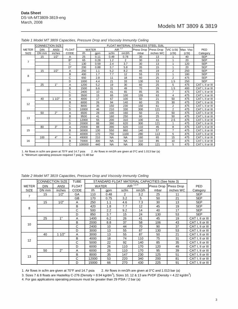
CONNECTION SIZE FLOAT MATERIAL STAINLESS STEEL 316LMETER DIN ANSI FLOAT WATER AIR 1,2 Press Drop Press Drop VIC (cSt) Max. Visc PED
SIZE DN mm inches CODE l/h gpm scfm nm3/h mbar inches WC (cSt) (cSt) Category15 1/2" A 25 0.11 0.49 0.78 30 13 1 40 SEP
B* 65 0.28 1.2 2 30 13 1 20 SEPC 130 0.59 2.4 3.7 30 13 1 120 SEPD* 200 0.88 3.7 5.8 35 15 1 20 SEP
15 1/2" A 250 1.1 5.2 8.2 45 19 2 250 SEPB 400 1.7 7.7 12 55 23 1 180 SEPC 650 2.8 11 18 60 25 2 475 SEPD 1000 4.4 21 33 130 53 1.5 250 SEP
25 1" A 1200 5.2 19 30 60 25 5 475 CAT I, II or IIIB 1500 6.6 31 49 70 29 1.5 400 CAT I, II or IIIC 2400 10 41 65 85 35 7 475 CAT I, II or IIID 3500 15 65 100 155 63 4 475 CAT I, II or III
40 1 1/2" A 4000 17 67 100 50 21 50 475 CAT I, II or IIIB 6000 26 94 140 60 25 30 475 CAT I, II or IIIC 8000 35 150 230 150 61 2 475 CAT I, II or IIID 10000 46 210 330 300 121 2 475 CAT I, II or III
50 2" A 6500 28 100 160 50 21 50 475 CAT I, II or IIIB 9500 41 160 250 60 25 50 475 CAT I, II or IIIC 12000 55 200 310 100 41 2.5 475 CAT I, II or IIID 20000 88 390 620 300 121 1 475 CAT I, II or III
80 3" A 20000 88 390 620 110 45 8 475 CAT I, II or IIIB 30000 130 550 860 140 57 7 475 CAT I, II or IIIC 40000 170 750 1100 280 113 5 475 CAT I, II or III
100 4" A 49000 210 NA NA 160 65 15 475 CAT I, II or IIIB 70000 300 NA NA 210 85 10 475 CAT I, II or IIIC 100000 440 NA NA 300 121 5 475 CAT I, II or III
1. Air flows in scfm are given at 70°F and 14.7 psia 2. Air flows in nm3/h are given at 0°C and 1.013 bar (a)3. *Minimum operating pressure required 7 psig / 0.48 bar
13
15
16
7
8
10
12
CONNECTION SIZE TUBE STANDARD FLOAT MATERIAL CAPACITIES (See Note 3)METER DIN ANSI FLOAT WATER AIR 1,2,4 Press Drop Press Drop PED
SIZE DN mm inches CODE l/h gpm scfm nm3/h mbar inches WC Category15 1/2" GA 110 0.48 2 3.2 25 11 SEP
GB 170 0.75 3.2 5 50 21 SEP15 1/2" A 250 1.1 4.6 7.3 30 13 SEP
B 420 1.8 7.7 12 45 19 SEPC 500 2.2 9.2 14 40 17 SEPD 850 3.7 15 24 130 53 SEP
25 1" A 1400 6.2 26 41 45 19 CAT I, II or IIIB 2000 8.8 37 58 106 43 CAT I, II or IIIC 2400 10 44 70 90 37 CAT I, II or IIID 3000 13 55 87 130 53 CAT I, II or III
40 1 1/2" A 3000 13 55 87 50 21 CAT I, II or IIIB 4000 18 74 110 75 31 CAT I, II or IIIC 5000 22 92 140 85 35 CAT I, II or IIID 6000 26 110 170 120 49 CAT I, II or III
50 2" A 6000 26 110 170 95 39 CAT I, II or IIIB 8000 35 147 230 125 51 CAT I, II or IIIC 12000 53 220 340 200 81 CAT I, II or IIID 15000 66 270 430 225 91 CAT I, II or III
1. Air flows in scfm are given at 70°F and 14.7 psia 2. Air flows in nm3/h are given at 0°C and 1.013 bar (a)3. Sizes 7 & 8 floats are Hastelloy C-276 (Density = 8.94 kg/dm3), Sizes 10, 12 & 13 are PVDF (Density = 4.22 kg/dm3)4. For gas applications operating pressure must be greater than 29 PSIA / 2 bar (a)
13
7
8
10
12
Table 1 Model MT 3809 Capacities, Pressure Drop and Viscosity Immunity Ceiling
Table 2 Model MT 3819 Capacities, Pressure Drop and Viscosity Immunity Ceiling
4
Models MT 3809 & 3819
Data SheetDS-VA-MT3809-3819-eng
March, 2008
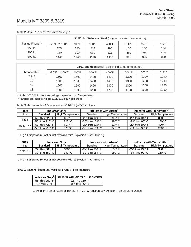
Table 2 Model MT 3809 Pressure Ratings*
617°F1200120012001000
600°F1200120012001000
500°F1300130013001100
400°F1400140014001200
300°F1400140014001200
Threaded NPT7 & 8
101213
200°F1500150015001300
-20°F to 100°F1500150015001300
316L Stainless Steel (psig at indicated temperature)
* Model MT 3819 pressure ratings dependent on flange rating.**Flanges are dual certified 316L/316 stainless steel.
617°F134448899
600°F140450905
500°F170480955
400°F195515
1030
300°F2155601120
Flange Rating**150 lb.300 lb.600 lb.
200°F2406201240
-20°F to 100°F2757201440
316/316L Stainless Steel (psig at indicated temperature)
Table 3 Maximum Fluid Temperatures at 104°F (40°C) Ambient
3809 Indicator Only Indicator with Alarm1 Indicator with Transmitter1
Size Standard High Temperature Standard High Temperature Standard High Temperature-58° thru 420° F 617° F -22° thru 320° F 450° F -22° thru 195° F 300° F-50° thru 215° C 325° C -30° thru 160° C 230° C -30° thru 90° C 150° C-58° thru 420° F 617° F -22° thru 320° F 617° F -22° thru 195° F 400° F-50° thru 215° C 325° C -30° thru 160° C 325° C -30° thru 90° C 200° C
1. High Temperature option not available with Explosion Proof Housing
3819 Indicator Only Indicator with Alarm1 Indicator with Transmitter1
Size Standard High Temperature Standard High Temperature Standard High Temperature-22° thru 300° F 300° F -22° thru 300° F 300° F -22° thru 195° F 300° F-30° thru 150° C 150° C -30° thru 150° C 150° C -30° thru 90° C 150° C
1. High Temperature option not available with Explosion Proof Housing
3809 & 3819 Minimum and Maximum Ambient Temeprature
Indicator Only1 Indicator with Alarm or Transmitter-58° thru 150° F-50° thru 65° C
1. Ambient Temperature below -22° F / -30° C requires Low Ambient Temperature Option
-22° thru 150° F-30° thru 65° C
7 & 8
10 thru 16
7 thru 13
5
Models MT 3809 & 3819
Data SheetDS-VA-MT3809-3819-engMarch, 2008
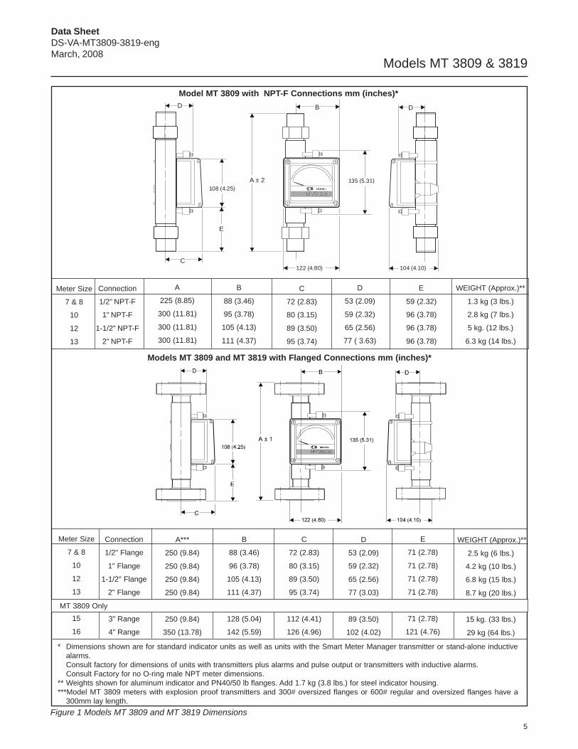
* Dimensions shown are for standard indicator units as well as units with the Smart Meter Manager transmitter or stand-alone inductivealarms.Consult factory for dimensions of units with transmitters plus alarms and pulse output or transmitters with inductive alarms.Consult Factory for no O-ring male NPT meter dimensions.
** Weights shown for aluminum indicator and PN40/50 lb flanges. Add 1.7 kg (3.8 lbs.) for steel indicator housing.***Model MT 3809 meters with explosion proof transmitters and 300# oversized flanges or 600# regular and oversized flanges have a
300mm lay length.
Connection
1/2" NPT-F
1" NPT-F
1-1/2" NPT-F
2" NPT-F
WEIGHT (Approx.)**
1.3 kg (3 lbs.)
2.8 kg (7 lbs.)
5 kg. (12 lbs.)
6.3 kg (14 lbs.)
D
53 (2.09)
59 (2.32)
65 (2.56)
77 ( 3.63)
E
59 (2.32)
96 (3.78)
96 (3.78)
96 (3.78)
C
72 (2.83)
80 (3.15)
89 (3.50)
95 (3.74)
A
225 (8.85)
300 (11.81)
300 (11.81)
300 (11.81)
Meter Size
7 & 8
10
12
13
B
88 (3.46)
95 (3.78)
105 (4.13)
111 (4.37)
Meter Size
7 & 8
10
12
13
15
16
B
88 (3.46)
96 (3.78)
105 (4.13)
111 (4.37)
128 (5.04)
142 (5.59)
E
71 (2.78)
71 (2.78)
71 (2.78)
71 (2.78)
71 (2.78)
121 (4.76)
D
53 (2.09)
59 (2.32)
65 (2.56)
77 (3.03)
89 (3.50)
102 (4.02)
C
72 (2.83)
80 (3.15)
89 (3.50)
95 (3.74)
112 (4.41)
126 (4.96)
Connection
1/2" Flange
1" Flange
1-1/2" Flange
2" Flange
3" Range
4" Range
A***
250 (9.84)
250 (9.84)
250 (9.84)
250 (9.84)
250 (9.84)
350 (13.78)
MT 3809 Only
Model MT 3809 with NPT-F Connections mm (inches)*B
135 (5.31)
122 (4.80)
A ± 2
D
104 (4.10)
D
E
C
108 (4.25)
Models MT 3809 and MT 3819 with Flanged Connections mm (inches)*
WEIGHT (Approx.)**
2.5 kg (6 lbs.)
4.2 kg (10 lbs.)
6.8 kg (15 lbs.)
8.7 kg (20 lbs.)
15 kg. (33 lbs.)
29 kg (64 lbs.)
Figure 1 Models MT 3809 and MT 3819 Dimensions
6
Models MT 3809 & 3819
Data SheetDS-VA-MT3809-3819-eng
March, 2008
Specifications - SMM Microprocessor Transmitterwith or without Alarm and Pulse Output
EMC Directive 89/336/EEC: EN 50081, EN 50082 and EN61326-1
Hazardous Location ClassificationEnclosure: Type 4X/ IP65Ambient Temperature: -22°F> Tamb < 150°F (-30°C > Tamb< 65°C)
Intrinsically SafeUnited States and Canada UL Listed, E73889, Vol. 1, Sect.15Class I, II and III, Division 1, Groups A, B, C, D, E, F, and G;T4
Europe – KEMA 01ATEX1235 X
II 2 G EEx ia IIC T4II 2 D T135oC
Entity Parameters (Transmitter):Ui=Vmax=30 Vdc; Ii=Imax=140 mA; Ci= 15 nF; Li= 0 mH
Entity Parameters (Integral Alarms):Ui=Vmax=30 Vdc; Ii=Imax=45 mA; Ci= 0 nF; Li= 0 mH
Non-IncendiveUnited States and Canada UL Listed, E73889, Vol. 1, Sect.15Class I, II, III, Division 2, Groups A, B, C,D F, and G; T4
Europe – KEMA 01ATEX1236
II 3 G EEx nA II T4II 3 D T135o C
Explosion- proof/ Flame-proofUnited States and Canada UL Listed, E73889, Vol. 1, Sect.14Class I, Division 1, Groups C, D;Dust Ignition-proof, Class II, Division 1, Groups E, F, G; ClassIII; T4
Europe – KEMA 01ATEX2207 X
II 2 G EEx d IIB T4II 2 D T135o C
Optional Electronic EquipmentMicroprocessor Transmitter With or Without Alarmsand Pulse Output Based on BrooksSmart Meter Manager TechnologyDesign Features• A 2-wire, loop-powered device for ease of wiring and
installation• 4-20 mA analog output for flowrate, with Bell-202
modulated HART communication channel• User selectable 0% and 100% analog output ranges
with optional smoothing• Flexible (mix & match) units of measure for flowrates,
totals, temperatures, densities, etc.• Two flow totalizers: Resettable and inventory
totalization• User configurable, scaleable pulse output for various
engineering units• Comprehensive alarms for both process flow and
internal diagnostic checks• Easily configured and compatible with other plant
equipment• Patented magnetic sensor which is resistant to external
magnetic fields
Description“Smart Inside” best defines the Brooks transmitter withoptional alarms and pulse output for totalization. Thetransmitter (with or without the alarms and pulse output)is a compact microprocessor device designed tointerface directly with the Models MT 3809 and MT 3819flowmeters. The microprocessor electronics are basedon the Brooks Smart Meter Manager (SMMTM)technology common to other Brooks flowmeters.
The transmitter is HART-programmable for numerousvariables such as flow rate, totalization, calibrationfactors, and high-low alarm parameters. It isprogrammable with easy-to-use hand heldconfigurators such as the EmersonTM HART 275Communicator. Prior to shipment, commonly useddefault values are programmed by Brooks to ensureease of operation and quick startup. However,parameters may be reprogrammed by the user ifneeded. The 2-wire electronics system is easy to installand interface with other existing equipment such asprocess management systems or maintenance controlpackages.
In operation the microprocessor transmitter convertsthe measured process flow into a 4-20mA output withHART protocol. The signal originates when the floatmagnet inside the metering tube passes a magneticsensor mounted on the transmitter. Flow rateinformation may be viewed locally at the meter scaleor displayed remotely (along with other flow data) as afunction of external support systems through analog/
pulse outputs or multiple digital communications.
In addition to transmitter features, this unit can also beordered with optional alarms and pulse output providedby open collector switches. One or two alarms may beprogrammed prior to shipment of the unit or at thecustomer site with a hand-held communicator.
7
Models MT 3809 & 3819
Data SheetDS-VA-MT3809-3819-engMarch, 2008
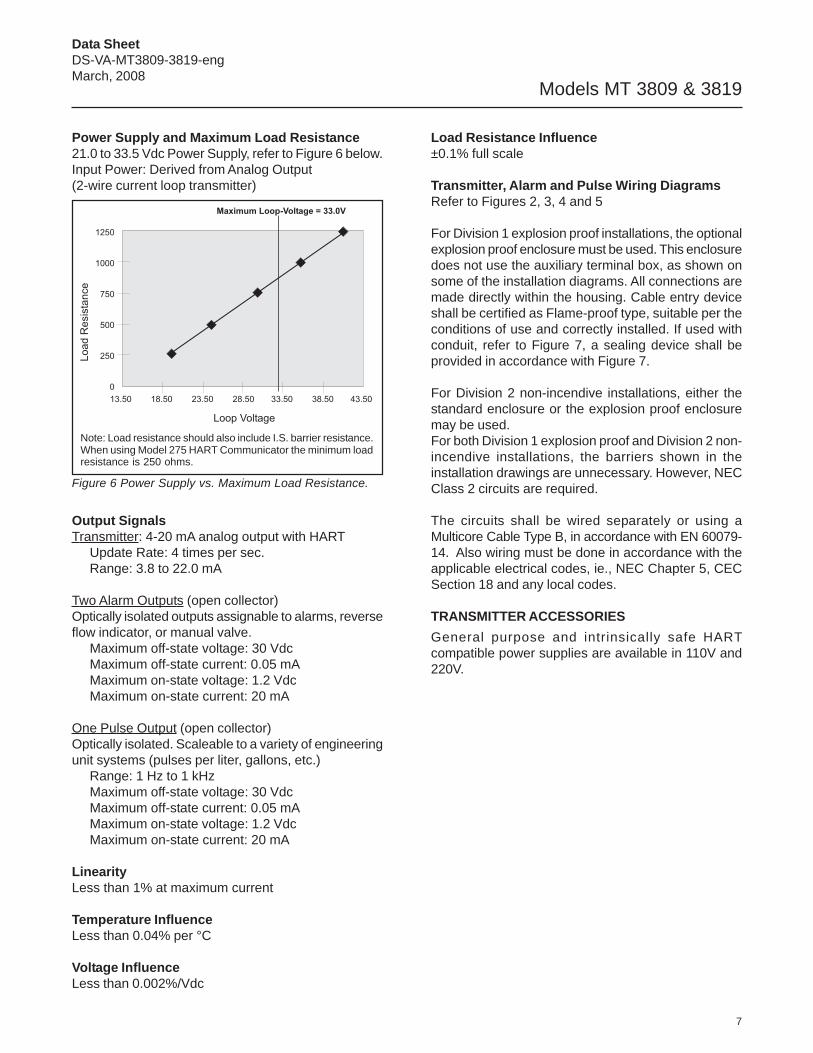
Power Supply and Maximum Load Resistance21.0 to 33.5 Vdc Power Supply, refer to Figure 6 below.Input Power: Derived from Analog Output(2-wire current loop transmitter)
Output SignalsTransmitter: 4-20 mA analog output with HART
Update Rate: 4 times per sec.Range: 3.8 to 22.0 mA
Two Alarm Outputs (open collector)Optically isolated outputs assignable to alarms, reverseflow indicator, or manual valve.
Maximum off-state voltage: 30 VdcMaximum off-state current: 0.05 mAMaximum on-state voltage: 1.2 VdcMaximum on-state current: 20 mA
One Pulse Output (open collector)Optically isolated. Scaleable to a variety of engineeringunit systems (pulses per liter, gallons, etc.)
Range: 1 Hz to 1 kHzMaximum off-state voltage: 30 VdcMaximum off-state current: 0.05 mAMaximum on-state voltage: 1.2 VdcMaximum on-state current: 20 mA
LinearityLess than 1% at maximum current
Temperature InfluenceLess than 0.04% per °C
Voltage InfluenceLess than 0.002%/Vdc
Figure 6 Power Supply vs. Maximum Load Resistance.
Note: Load resistance should also include I.S. barrier resistance.When using Model 275 HART Communicator the minimum loadresistance is 250 ohms.
Load Resistance Influence±0.1% full scale
Transmitter, Alarm and Pulse Wiring DiagramsRefer to Figures 2, 3, 4 and 5
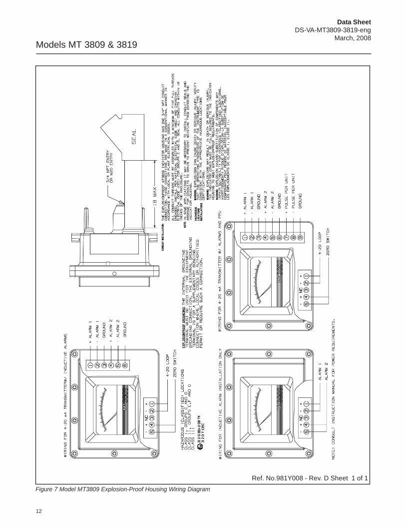
For Division 1 explosion proof installations, the optionalexplosion proof enclosure must be used. This enclosuredoes not use the auxiliary terminal box, as shown onsome of the installation diagrams. All connections aremade directly within the housing. Cable entry deviceshall be certified as Flame-proof type, suitable per theconditions of use and correctly installed. If used withconduit, refer to Figure 7, a sealing device shall beprovided in accordance with Figure 7.
For Division 2 non-incendive installations, either thestandard enclosure or the explosion proof enclosuremay be used.For both Division 1 explosion proof and Division 2 non-incendive installations, the barriers shown in theinstallation drawings are unnecessary. However, NECClass 2 circuits are required.
The circuits shall be wired separately or using aMulticore Cable Type B, in accordance with EN 60079-14. Also wiring must be done in accordance with theapplicable electrical codes, ie., NEC Chapter 5, CECSection 18 and any local codes.
TRANSMITTER ACCESSORIESGeneral purpose and intrinsically safe HARTcompatible power supplies are available in 110V and220V.
8
Models MT 3809 & 3819
Data SheetDS-VA-MT3809-3819-eng
March, 2008
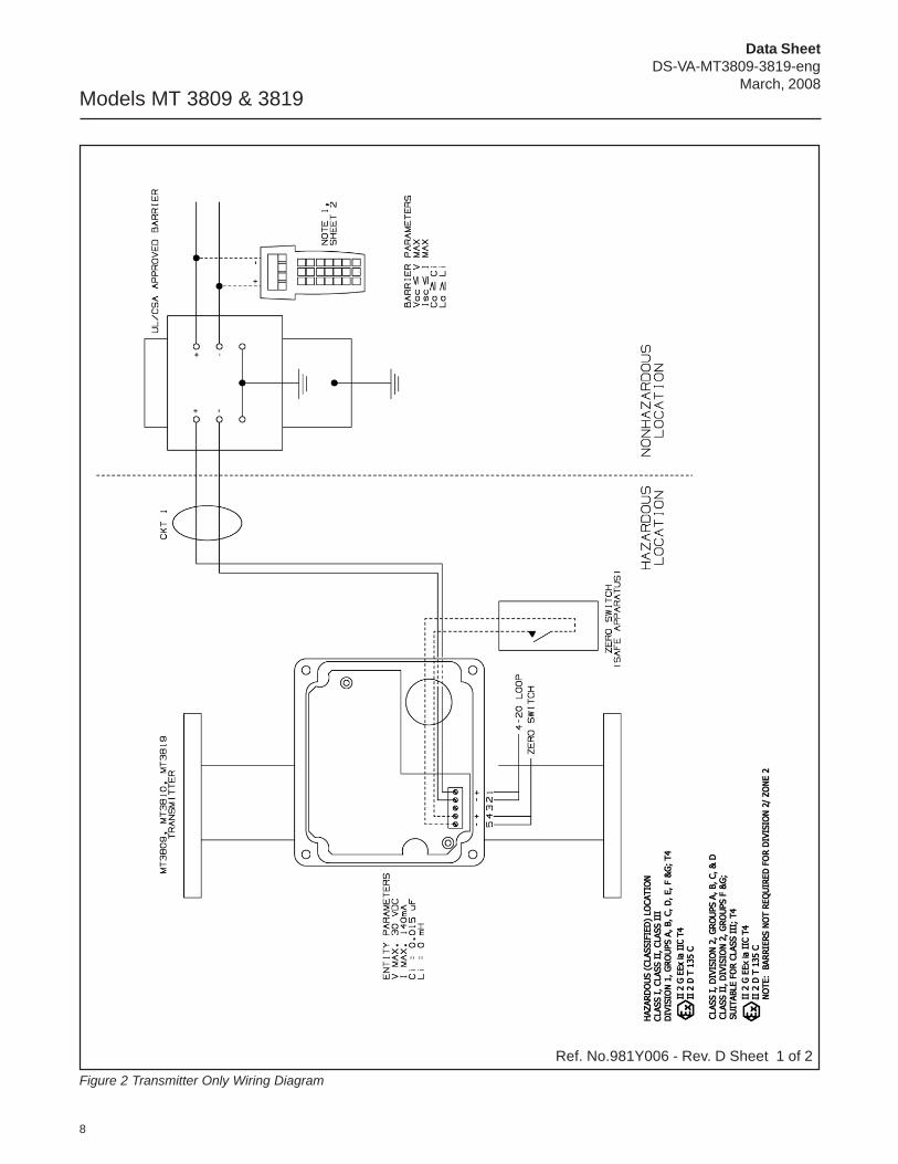
Ref. No.981Y006 - Rev. D Sheet 1 of 2Figure 2 Transmitter Only Wiring Diagram
9
Models MT 3809 & 3819
Data SheetDS-VA-MT3809-3819-engMarch, 2008
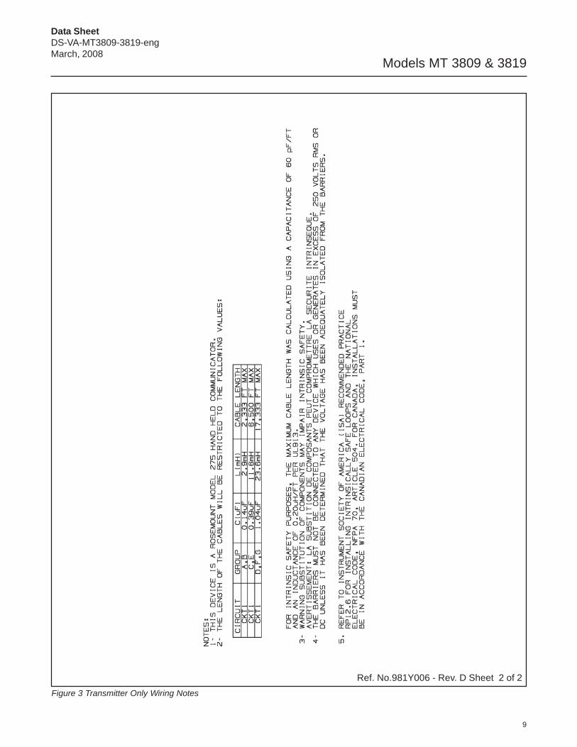
Figure 3 Transmitter Only Wiring Notes
Ref. No.981Y006 - Rev. D Sheet 2 of 2
10
Models MT 3809 & 3819
Data SheetDS-VA-MT3809-3819-eng
March, 2008
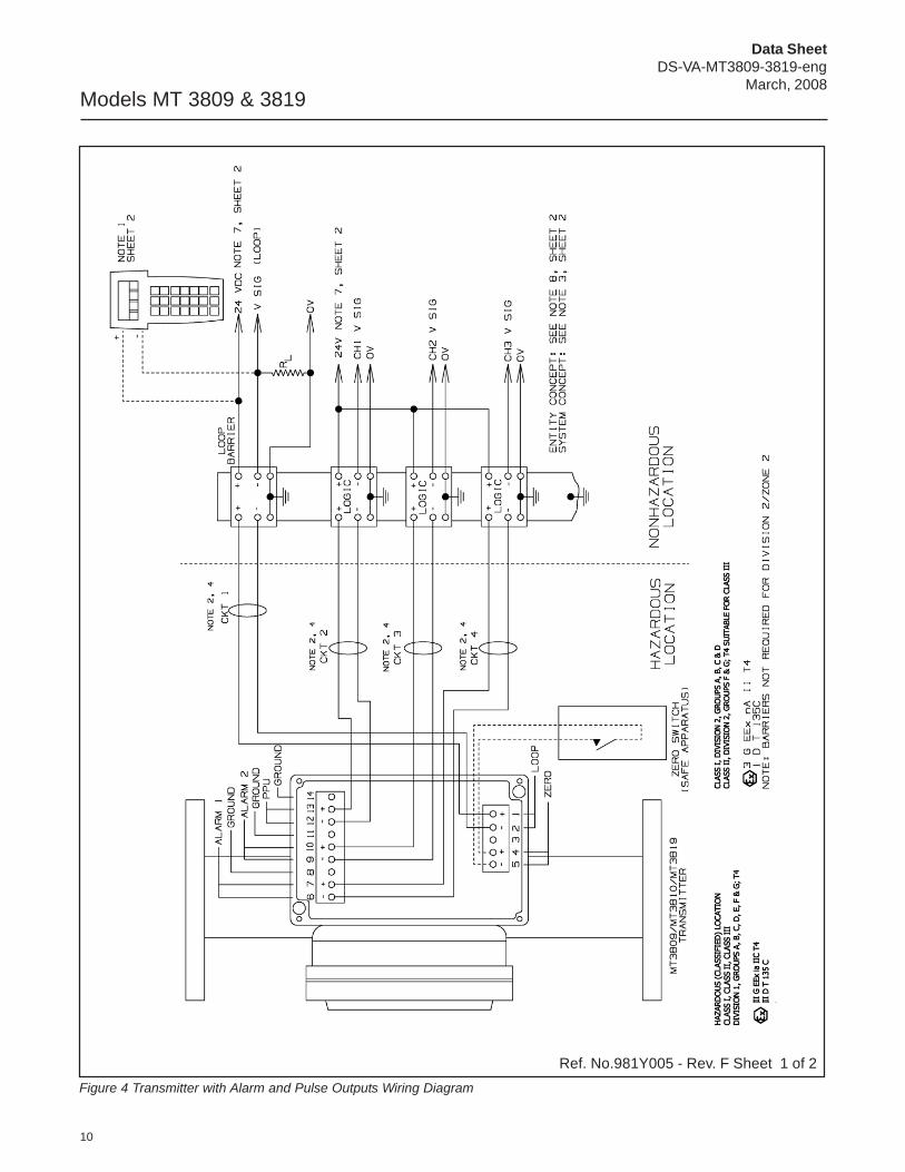
Ref. No.981Y005 - Rev. F Sheet 1 of 2Figure 4 Transmitter with Alarm and Pulse Outputs Wiring Diagram
11
Models MT 3809 & 3819
Data SheetDS-VA-MT3809-3819-engMarch, 2008
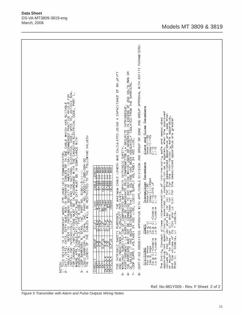
Figure 5 Transmitter with Alarm and Pulse Outputs Wiring Notes
Ref. No.981Y005 - Rev. F Sheet 2 of 2
12
Models MT 3809 & 3819
Data SheetDS-VA-MT3809-3819-eng
March, 2008
Ref. No.981Y008 - Rev. D Sheet 1 of 1Figure 7 Model MT3809 Explosion-Proof Housing Wiring Diagram
13
Models MT 3809 & 3819
Data SheetDS-VA-MT3809-3819-engMarch, 2008
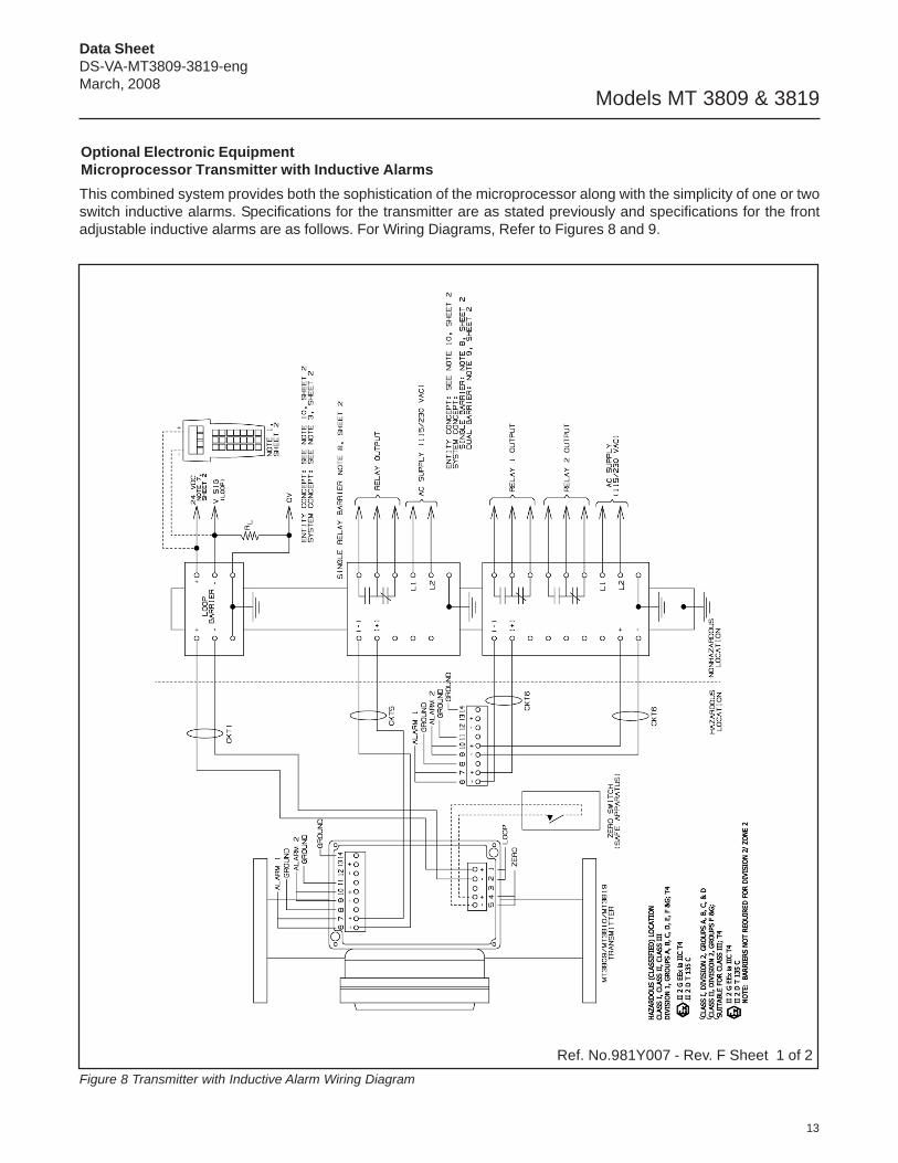
Figure 8 Transmitter with Inductive Alarm Wiring Diagram
Ref. No.981Y007 - Rev. F Sheet 1 of 2
Optional Electronic EquipmentMicroprocessor Transmitter with Inductive AlarmsThis combined system provides both the sophistication of the microprocessor along with the simplicity of one or twoswitch inductive alarms. Specifications for the transmitter are as stated previously and specifications for the frontadjustable inductive alarms are as follows. For Wiring Diagrams, Refer to Figures 8 and 9.
14
Models MT 3809 & 3819
Data SheetDS-VA-MT3809-3819-eng
March, 2008
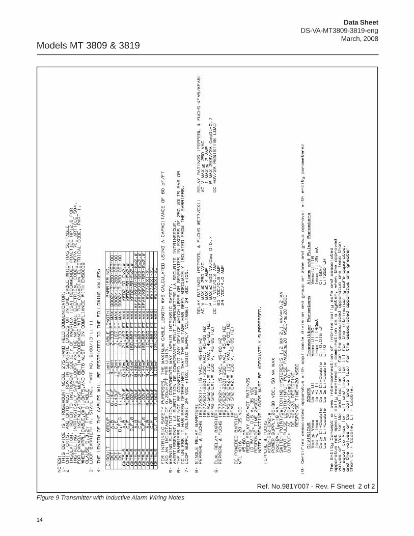
Ref. No.981Y007 - Rev. F Sheet 2 of 2Figure 9 Transmitter with Inductive Alarm Wiring Notes
15
Models MT 3809 & 3819
Data SheetDS-VA-MT3809-3819-engMarch, 2008
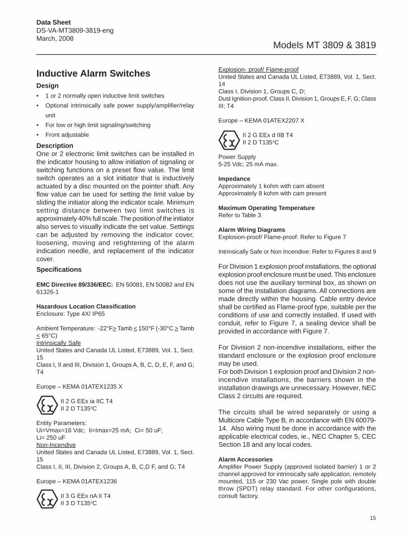
Inductive Alarm SwitchesDesign• 1 or 2 normally open inductive limit switches• Optional intrinsically safe power supply/amplifier/relay
unit• For low or high limit signaling/switching• Front adjustable
DescriptionOne or 2 electronic limit switches can be installed inthe indicator housing to allow initiation of signaling orswitching functions on a preset flow value. The limitswitch operates as a slot initiator that is inductivelyactuated by a disc mounted on the pointer shaft. Anyflow value can be used for setting the limit value bysliding the initiator along the indicator scale. Minimumsetting distance between two limit switches isapproximately 40% full scale. The position of the initiatoralso serves to visually indicate the set value. Settingscan be adjusted by removing the indicator cover,loosening, moving and retightening of the alarmindication needle, and replacement of the indicatorcover.Specifications
EMC Directive 89/336/EEC: EN 50081, EN 50082 and EN61326-1
Hazardous Location ClassificationEnclosure: Type 4X/ IP65
Ambient Temperature: -22°F> Tamb < 150°F (-30°C > Tamb< 65°C)Intrinsically SafeUnited States and Canada UL Listed, E73889, Vol. 1, Sect.15Class I, II and III, Division 1, Groups A, B, C, D, E, F, and G;T4
Europe – KEMA 01ATEX1235 X
II 2 G EEx ia IIC T4II 2 D T135oC
Entity Parameters:Ui=Vmax=16 Vdc; Ii=Imax=25 mA; Ci= 50 uF;Li= 250 uFNon-IncendiveUnited States and Canada UL Listed, E73889, Vol. 1, Sect.15Class I, II, III, Division 2, Groups A, B, C,D F, and G; T4
Europe – KEMA 01ATEX1236
II 3 G EEx nA II T4II 3 D T135oC
Explosion- proof/ Flame-proofUnited States and Canada UL Listed, E73889, Vol. 1, Sect.14Class I, Division 1, Groups C, D;Dust Ignition-proof, Class II, Division 1, Groups E, F, G; ClassIII; T4
Europe – KEMA 01ATEX2207 X
II 2 G EEx d IIB T4II 2 D T135oC
Power Supply5-25 Vdc; 25 mA max.
ImpedanceApproximately 1 kohm with cam absentApproximately 8 kohm with cam present
Maximum Operating TemperatureRefer to Table 3
Alarm Wiring DiagramsExplosion-proof/ Flame-proof: Refer to Figure 7
Intrinsically Safe or Non Incendive: Refer to Figures 8 and 9
For Division 1 explosion proof installations, the optionalexplosion proof enclosure must be used. This enclosuredoes not use the auxiliary terminal box, as shown onsome of the installation diagrams. All connections aremade directly within the housing. Cable entry deviceshall be certified as Flame-proof type, suitable per theconditions of use and correctly installed. If used withconduit, refer to Figure 7, a sealing device shall beprovided in accordance with Figure 7.
For Division 2 non-incendive installations, either thestandard enclosure or the explosion proof enclosuremay be used.For both Division 1 explosion proof and Division 2 non-incendive installations, the barriers shown in theinstallation drawings are unnecessary. However, NECClass 2 circuits are required.
The circuits shall be wired separately or using aMulticore Cable Type B, in accordance with EN 60079-14. Also wiring must be done in accordance with theapplicable electrical codes, ie., NEC Chapter 5, CECSection 18 and any local codes.
Alarm AccessoriesAmplifier Power Supply (approved isolated barrier) 1 or 2channel approved for intrinsically safe application, remotelymounted, 115 or 230 Vac power. Single pole with doublethrow (SPDT) relay standard. For other configurations,consult factory.
16
Models MT 3809 & 3819
Data SheetDS-VA-MT3809-3819-eng
March, 2008
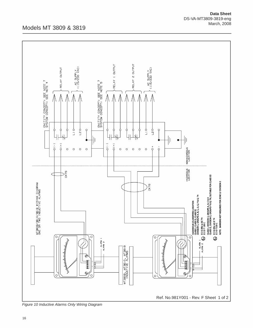
Ref. No.981Y001 - Rev. F Sheet 1 of 2Figure 10 Inductive Alarms Only Wiring Diagram
17
Models MT 3809 & 3819
Data SheetDS-VA-MT3809-3819-engMarch, 2008
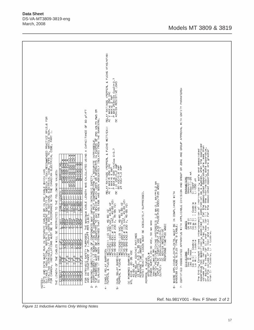
Figure 11 Inductive Alarms Only Wiring Notes
Ref. No.981Y001 - Rev. F Sheet 2 of 2
18
Models MT 3809 & 3819
Data SheetDS-VA-MT3809-3819-eng
March, 2008
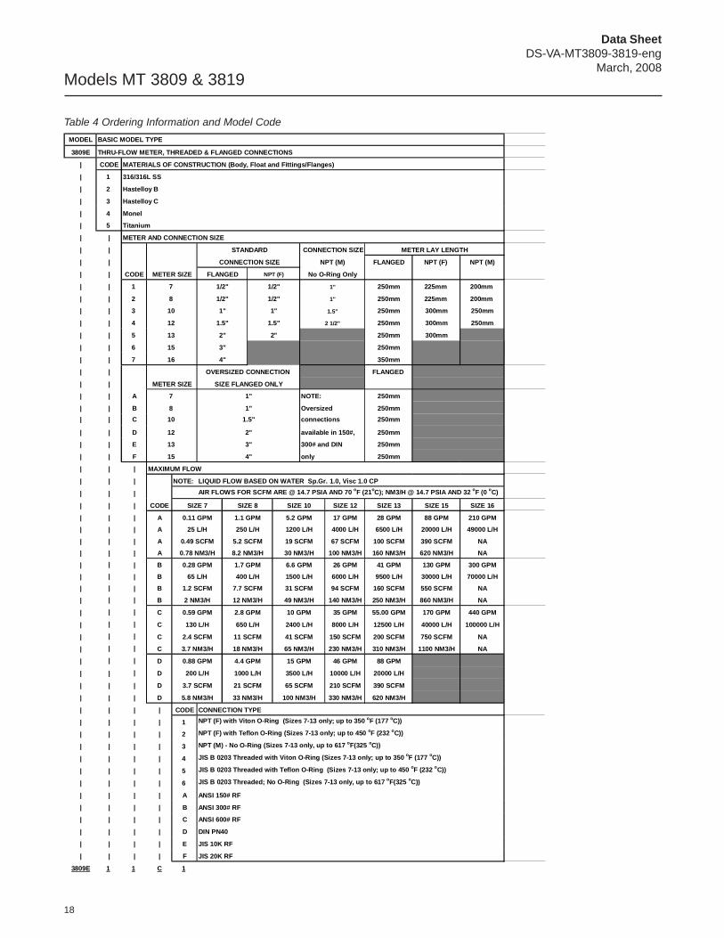
Table 4 Ordering Information and Model CodeMODEL BASIC MODEL TYPE
3809E THRU-FLOW METER, THREADED & FLANGED CONNECTIONS
| CODE MATERIALS OF CONSTRUCTION (Body, Float and Fittings/Flanges)
| 1 316/316L SS
| 2 Hastelloy B
| 3 Hastelloy C
| 4 Monel
| 5 Titanium
| | METER AND CONNECTION SIZE
| | STANDARD CONNECTION SIZE METER LAY LENGTH
| | CONNECTION SIZE NPT (M) FLANGED NPT (F) NPT (M)
| | CODE METER SIZE FLANGED NPT (F) No O-Ring Only
| | 1 7 1/2" 1/2" 1" 250mm 225mm 200mm
| | 2 8 1/2" 1/2" 1" 250mm 225mm 200mm
| | 3 10 1" 1" 1.5" 250mm 300mm 250mm
| | 4 12 1.5" 1.5" 2 1/2" 250mm 300mm 250mm
| | 5 13 2" 2" 250mm 300mm
| | 6 15 3" 250mm
| | 7 16 4" 350mm
| | OVERSIZED CONNECTION FLANGED
| | METER SIZE SIZE FLANGED ONLY
| | A 7 1" NOTE: 250mm
| | B 8 1" Oversized 250mm| | C 10 1.5" connections 250mm
| | D 12 2" available in 150#, 250mm
| | E 13 3" 300# and DIN 250mm
| | F 15 4" only 250mm
| | | MAXIMUM FLOW
| | | NOTE: LIQUID FLOW BASED ON WATER Sp.Gr. 1.0, Visc 1.0 CP
| | | AIR FLOWS FOR SCFM ARE @ 14.7 PSIA AND 70 oF (21oC); NM3/H @ 14.7 PSIA AND 32 oF (0 oC)
| | | CODE SIZE 7 SIZE 8 SIZE 10 SIZE 12 SIZE 13 SIZE 15 SIZE 16
| | | A 0.11 GPM 1.1 GPM 5.2 GPM 17 GPM 28 GPM 88 GPM 210 GPM
| | | A 25 L/H 250 L/H 1200 L/H 4000 L/H 6500 L/H 20000 L/H 49000 L/H
| | | A 0.49 SCFM 5.2 SCFM 19 SCFM 67 SCFM 100 SCFM 390 SCFM NA
| | | A 0.78 NM3/H 8.2 NM3/H 30 NM3/H 100 NM3/H 160 NM3/H 620 NM3/H NA
| | | B 0.28 GPM 1.7 GPM 6.6 GPM 26 GPM 41 GPM 130 GPM 300 GPM
| | | B 65 L/H 400 L/H 1500 L/H 6000 L/H 9500 L/H 30000 L/H 70000 L/H
| | | B 1.2 SCFM 7.7 SCFM 31 SCFM 94 SCFM 160 SCFM 550 SCFM NA
| | | B 2 NM3/H 12 NM3/H 49 NM3/H 140 NM3/H 250 NM3/H 860 NM3/H NA
| | | C 0.59 GPM 2.8 GPM 10 GPM 35 GPM 55.00 GPM 170 GPM 440 GPM
| | | C 130 L/H 650 L/H 2400 L/H 8000 L/H 12500 L/H 40000 L/H 100000 L/H
| | | C 2.4 SCFM 11 SCFM 41 SCFM 150 SCFM 200 SCFM 750 SCFM NA
| | | C 3.7 NM3/H 18 NM3/H 65 NM3/H 230 NM3/H 310 NM3/H 1100 NM3/H NA
| | | D 0.88 GPM 4.4 GPM 15 GPM 46 GPM 88 GPM
| | | D 200 L/H 1000 L/H 3500 L/H 10000 L/H 20000 L/H
| | | D 3.7 SCFM 21 SCFM 65 SCFM 210 SCFM 390 SCFM
| | | D 5.8 NM3/H 33 NM3/H 100 NM3/H 330 NM3/H 620 NM3/H
| | | | CODE CONNECTION TYPE
| | | | 1 NPT (F) with Viton O-Ring (Sizes 7-13 only; up to 350 oF (177 oC))
| | | | 2 NPT (F) with Teflon O-Ring (Sizes 7-13 only; up to 450 oF (232 oC))
| | | | 3 NPT (M) - No O-Ring (Sizes 7-13 only, up to 617 oF(325 oC))
| | | | 4 JIS B 0203 Threaded with Viton O-Ring (Sizes 7-13 only; up to 350 oF (177 oC))
| | | | 5 JIS B 0203 Threaded with Teflon O-Ring (Sizes 7-13 only; up to 450 oF (232 oC))
| | | | 6 JIS B 0203 Threaded; No O-Ring (Sizes 7-13 only, up to 617 oF(325 oC))
| | | | A ANSI 150# RF
| | | | B ANSI 300# RF
| | | | C ANSI 600# RF
| | | | D DIN PN40
| | | | E JIS 10K RF
| | | | F JIS 20K RF
3809E 1 1 C 1
19
Models MT 3809 & 3819
Data SheetDS-VA-MT3809-3819-engMarch, 2008
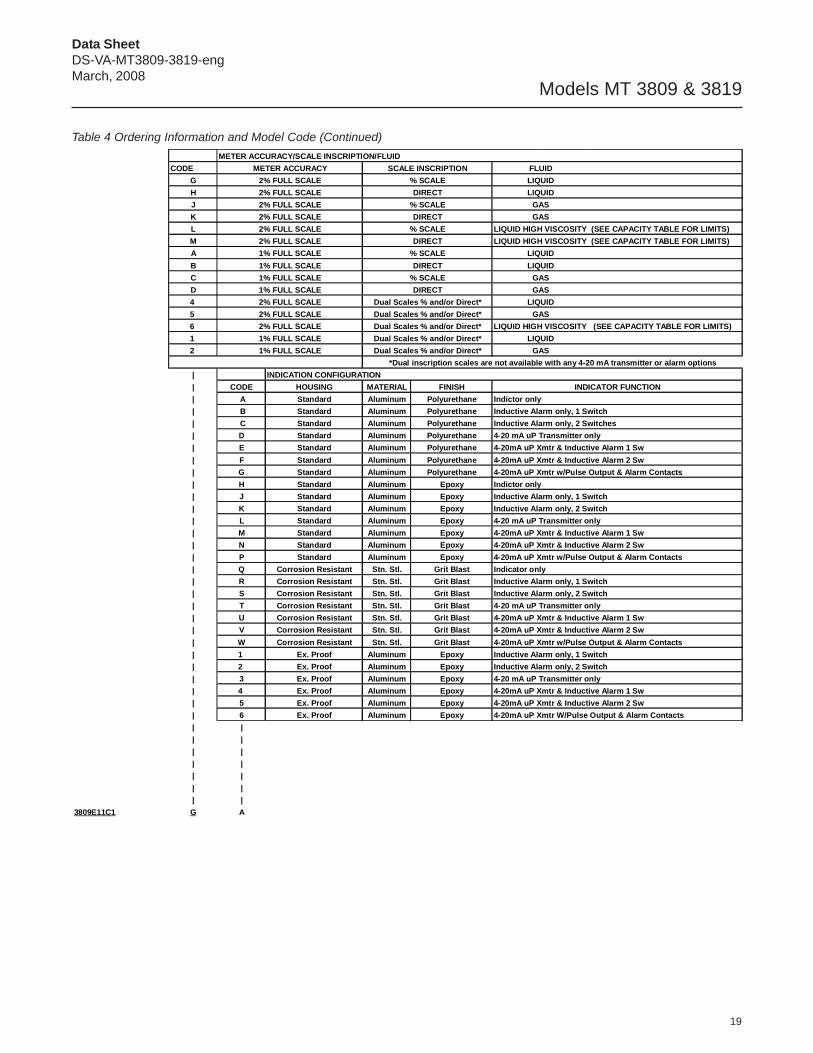
METER ACCURACY/SCALE INSCRIPTION/FLUIDCODE METER ACCURACY SCALE INSCRIPTION FLUID
G 2% FULL SCALE % SCALE LIQUIDH 2% FULL SCALE DIRECT LIQUIDJ 2% FULL SCALE % SCALE GASK 2% FULL SCALE DIRECT GASL 2% FULL SCALE % SCALE LIQUID HIGH VISCOSITY (SEE CAPACITY TABLE FOR LIMITS)M 2% FULL SCALE DIRECT LIQUID HIGH VISCOSITY (SEE CAPACITY TABLE FOR LIMITS)A 1% FULL SCALE % SCALE LIQUIDB 1% FULL SCALE DIRECT LIQUIDC 1% FULL SCALE % SCALE GASD 1% FULL SCALE DIRECT GAS4 2% FULL SCALE Dual Scales % and/or Direct* LIQUID5 2% FULL SCALE Dual Scales % and/or Direct* GAS6 2% FULL SCALE Dual Scales % and/or Direct* LIQUID HIGH VISCOSITY (SEE CAPACITY TABLE FOR LIMITS)1 1% FULL SCALE Dual Scales % and/or Direct* LIQUID2 1% FULL SCALE Dual Scales % and/or Direct* GAS
*Dual inscription scales are not available with any 4-20 mA transmitter or alarm options| INDICATION CONFIGURATION| CODE HOUSING MATERIAL FINISH INDICATOR FUNCTION| A Standard Aluminum Polyurethane Indictor only| B Standard Aluminum Polyurethane Inductive Alarm only, 1 Switch| C Standard Aluminum Polyurethane Inductive Alarm only, 2 Switches| D Standard Aluminum Polyurethane 4-20 mA uP Transmitter only| E Standard Aluminum Polyurethane 4-20mA uP Xmtr & Inductive Alarm 1 Sw| F Standard Aluminum Polyurethane 4-20mA uP Xmtr & Inductive Alarm 2 Sw| G Standard Aluminum Polyurethane 4-20mA uP Xmtr w/Pulse Output & Alarm Contacts| H Standard Aluminum Epoxy Indictor only| J Standard Aluminum Epoxy Inductive Alarm only, 1 Switch| K Standard Aluminum Epoxy Inductive Alarm only, 2 Switch| L Standard Aluminum Epoxy 4-20 mA uP Transmitter only| M Standard Aluminum Epoxy 4-20mA uP Xmtr & Inductive Alarm 1 Sw| N Standard Aluminum Epoxy 4-20mA uP Xmtr & Inductive Alarm 2 Sw| P Standard Aluminum Epoxy 4-20mA uP Xmtr w/Pulse Output & Alarm Contacts| Q Corrosion Resistant Stn. Stl. Grit Blast Indicator only| R Corrosion Resistant Stn. Stl. Grit Blast Inductive Alarm only, 1 Switch| S Corrosion Resistant Stn. Stl. Grit Blast Inductive Alarm only, 2 Switch| T Corrosion Resistant Stn. Stl. Grit Blast 4-20 mA uP Transmitter only| U Corrosion Resistant Stn. Stl. Grit Blast 4-20mA uP Xmtr & Inductive Alarm 1 Sw| V Corrosion Resistant Stn. Stl. Grit Blast 4-20mA uP Xmtr & Inductive Alarm 2 Sw| W Corrosion Resistant Stn. Stl. Grit Blast 4-20mA uP Xmtr w/Pulse Output & Alarm Contacts| 1 Ex. Proof Aluminum Epoxy Inductive Alarm only, 1 Switch| 2 Ex. Proof Aluminum Epoxy Inductive Alarm only, 2 Switch| 3 Ex. Proof Aluminum Epoxy 4-20 mA uP Transmitter only| 4 Ex. Proof Aluminum Epoxy 4-20mA uP Xmtr & Inductive Alarm 1 Sw| 5 Ex. Proof Aluminum Epoxy 4-20mA uP Xmtr & Inductive Alarm 2 Sw| 6 Ex. Proof Aluminum Epoxy 4-20mA uP Xmtr W/Pulse Output & Alarm Contacts| || || || || || || |
3809E11C1 G A
Table 4 Ordering Information and Model Code (Continued)
20
Models MT 3809 & 3819
Data SheetDS-VA-MT3809-3819-eng
March, 2008
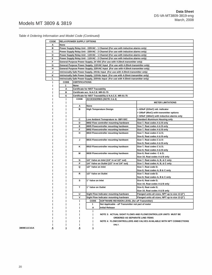
CODE RELAY/POWER SUPPLY OPTIONS A NoneB Power Supply Relay Unit - 220VAC - 1 Channel (For use with inductive alarms only)C Power Supply Relay Unit - 220VAC - 2 Channel (For use with inductive alarms only)D Power Supply Relay Unit - 110VAC - 1 Channel (For use with inductive alarms only)E Power Supply Relay Unit - 110VAC - 2 Channel (For use with inductive alarms only)F General Purpose Power Supply, 24 VDC (For use with 4-20mA transmitter only)G General Purpose Power Supply, 110VAC Input (For use with 4-20mA transmitter only)H General Purpose Power Supply, 220VAC Input (For use with 4-20mA transmitter only) J Intrinsically Safe Power Supply, 24Vdc Input (For use with 4-20mA transmitter only)K Intrinsically Safe Power Supply, 110Vdc Input (For use with 4-20mA transmitter only)L Intrinsically Safe Power Supply, 220Vdc Input (For use with 4-20mA transmitter only)| CODE CERTIFICATIONS| 1 None| A Certificate for NIST Traceability| B Certificate acc. N.A.C.E. MR-01-75| G Certificate for NIST Traceability & N.A.C.E. MR-01-75| | CODE ACCESSORIES (NOTE 3 & 4)| | METER LIMITATIONS| | A None| | B High Temperature Design > 420oF (215oC) std. indicator| | > 195oF (90oC) with transmitter options| | > 320oF (160oC) with inductive alarms only| | C Low Ambient Temeprature to -58F/-50C Standard Aluminum Housing only| | D 8802 Flow controller mounting hardware Size 7, float codes A & B only| | E 8805 Flowcontroller mounting hardware Size 7, float codes A & B only| | F 8902 Flowcontroller mounting hardware Size 7, float codes A & B only| | H 8810 Flowcontroller mounting hardware Size 7, float codes C & D; | | Size 8, float codes A & B only| | J 8815 Flowcontroller mounting hardware Size 7, float codes C & D:| | Size 8, float codes A & B only| | K 8910 Flowcontroller mounting hardware Size 7, float codes C & D;| | Size 8, float codes A & B only| | M 8830 Flowcontroller mounting hardware Size 8, float codes C & D;| | Size 10, float codes A & B only| | N 1/4" Valve on Inlet (1/4" in w/ 1/2" out) Size 7, float codes A, B, & C only| | P 1/4" Valve on Outlet (1/2" in w/ 1/4" out) Size 7, float codes A, B, & C only| | Q 1/2" Valve on Inlet Size 7, float code D;| | Size 8, float codes A, B & C only| | R 1/2" Valve on Outlet Size 7, float code D;| | Size 8, float codes A, B & C only| | S 1" Valve on Inlet Size 8, float code D;| | Size 10, float codes A & B only| | T 1" Valve on Outlet Size 8, float code D;| | Size 10, float codes A & B only| | U Sight Flow Indicator mounting hardware Flanged units all sizes; NPT up to size 13 (2")| | V Sight Flow Indicator mounting hardware Flanged units all sizes; NPT up to size 13 (2")| | | CODE SOFTWARE REVISION LEVEL (for uP Transmitter)| | | 1 Not Applicable - uP Transmitter not part of meter| | | A Initial Release| | | || | | | NOTE 3: ACTUAL SIGHT FLOWS AND FLOWCONTROLLER UNITS MUST BE| | | | ORDERED AS SEPARATE LINE ITEMS | | | | NOTE 4: FLOWCONTROLLERS AND VALVES AVAILABLE WITH NPT CONNECTIONS| | | | ONLY.
3809E11C1GA A 1 A 1
Table 4 Ordering Information and Model Code (Continued)
21
Models MT 3809 & 3819
Data SheetDS-VA-MT3809-3819-engMarch, 2008
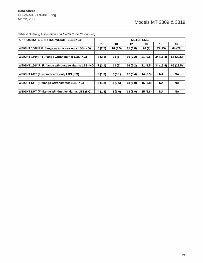
Table 4 Ordering Information and Model Code (Continued)
APPROXIMATE SHIPPING WEIGHT LBS (KG): METER SIZE 7-8 10 12 13 15 16
WEIGHT 150# R.F. flange w/ indicator only LBS (KG) 6 (2.7) 10 (4.5) 15 (6.8) 20 (9) 33 (15) 64 (29)
WEIGHT 150# R. F. flange w/transmitter LBS (KG) 7 (3.1) 11 (5) 16 (7.2) 21 (9.5) 34 (15.4) 65 (29.5)
WEIGHT 150# R. F. flange w/inductive alarms LBS (KG) 7 (3.1) 11 (5) 16 (7.2) 21 (9.5) 34 (15.4) 65 (29.5)
WEIGHT NPT (F) w/ indicator only LBS (KG) 3 (1.3) 7 (3.1) 12 (5.4) 14 (6.3) NA NA
WEIGHT NPT (F) flange w/transmitter LBS (KG) 4 (1.8) 8 (3.6) 13 (5.9) 15 (6.8) NA NA
WEIGHT NPT (F) flange w/inductive alarms LBS (KG) 4 (1.8) 8 (3.6) 13 (5.9) 15 (6.8) NA NA
22
Models MT 3809 & 3819
Data SheetDS-VA-MT3809-3819-eng
March, 2008
BROOKS LOCAL AND WORLDWIDE SUPPORTBrooks Instrument provides sales and service facilities around the world, ensuring quick delivery from local stock,timely repairs and local based sales and service facilities.Our dedicated flow experts provide consultation and support, assuring successful applications of the Brooks flowmeasurement and control products.Calibration facilities are available in local sales and service offices. The primary standard calibration equipment tocalibrate our flow products is certified by our local Weights and Measures Authorities and traceable to the relevantinternational standards.
START-UP SERVICE AND IN-SITU CALIBRATIONBrooks Instrument can provide start-up service prior to operation when required.For some process applications, where ISO-9001 Quality Certification is important, it is mandatory to verify and/or(re)calibrate the products periodically. In many cases this service can be provided under in-situ conditions, and theresults will be traceable to the relevant international quality standards.
CUSTOMER SEMINARS AND TRAININGBrooks Instrument can provide customer seminars and dedicated training to engineers, end users andmaintenance persons. Please contact your nearest sales representative for more details.
HELP DESKIn case you need technical assistance:
Americas 1-888-554-FLOWEurope +(31) 318 549 290 Within Netherlands 0318 549 290Asia +011-81-3-5633-7100
Due to Brooks Instrument's commitment to continuous improvement of our products, all specifications are subject to changewithout notice.
TRADEMARKSBrooks ........................................................... Brooks Instrument, LLCEmerson ........................................................... Emerson Electric Co.HART ......................................... HART Communications FoundationHastelloy B, C ................................... E.I. DuPont de Nemours & Co.Inconel .................................................... Inco Alloy International Inc.Smart Meter Manager ....................................... Brooks Instrument, LLCSMM .............................................................. Brooks Instrument, LLCTeflon ................................................ E.I. DuPont de Nemours & Co.Tefzel ................................................ E.I. DuPont de Nemours & Co.Viton ............................................... DuPont Performance Elastomers