Embed Size (px)
Citation preview

broadcast
MC MARTI N
McMartin Industries Inc. 4500 South 76th Street Omaha. Nebraska 68127 (402) 331 -2000 Telex 484485
250 -1,500 WATT FM TRANSMITTER BF -1M . : E r ^ ' . + ` .
'.7/44f:; E
.j/,r
f
1`r
.' ..
21. f 4
Y
r.
. ` . .
'
r ; .1. . .1 ...'
, `=
f .t e .V ^+,L r.f 'r J. . .,,I. : +f. n Z . ¡"w ,* I
, a , " .. F . ;..rip , r e :
! f A` *
-". . - rsF Y
) :b
4da iti-,+ +t 7' ' . 'LAI. k t ,A r_ r. 4 .{ r+ L `^ iTlMM ik .t,4i . .
. .a,,;..t a .. 3 r t r41; r z. f
} i xf` iil ' i ¡'. i .M - d * y.' ..-t :t ; . ,,,;
IMAM/MN 1111.11,4
s
...,< Ast. R - 'y ,
s- +
f
4.y;)(!`°~ .. . r, ri
i,.
:
MC MARTIN f
! ` i Z u
, . .. . v,

MC MARTIN BF-1M TRANSMITTER
EXCELLENT PA EFFICIENCY - 70 80%
OVERLOAD -STATUS LIGHTS BUILT-IN
AUTOMATIC RECYCLING
PA- OVERLOAD AND VSWR SENSING BUILT-IN
NO NEUTRALIZATION REQUIRED
Topnotch performance at output levels in the .25 to 1.5 kW range is assured by the McMartin Model BF -1 M FM
Broadcast transmitter. The BF -1 M is FCC Type Accepted at these power ranges.
Designed for operation on any specified frequency from 88 to 108 MegaHertz, the BF -1M, with its grounded grid Class C PA stage, assures excellent bandwidth charac- teristics essential to the stringent demands of stereophonic and SCA multiplex transmission today.
The power amplifier stage uses a ceramic /metal, zero - bias, hi -mu triode - the 3CX1500/A7. As a grounded grid Class C amplifier, this tube requires no neutraliza- tion, nor grid bias and screen grid power supplies. The elimination of these many components, required for power tetrode PA stages, contributes both to long -term reliability and stability and a remarkably simple and straightforward power output RF stage design.
The PA tube is driven by a solid -state intermediate power amplifier stage following the field -proven, high - performance McMartin Model BFM -15 solid state ex- citer, of modular plug -in design. Stereo or SCA multiplex capability is easily attained by use of the optional modu- lar stereo and SCA generator assemblies.
The heart of the BF-1M is the advanced McMartin BFM -15, high performance, fully modular FM exciter. Optional plug -in circuit cards allow the user to add SCA, stereo and audio processing functions within the exciter cabinet.
The audio processor is McMartin's Exclusive Maxi-I, an exceptionally responsive design which assures maximum program loudness and limits overshoot to less than 2 %.
The BFM -15 replaces the McMartin B -910 exciter used in the "K" series FM transmitters and provides superior performance that includes improved stereo separation, lower SCA distortion, and extremely low SCA crosstalk into the main channel; lower, in fact, than the noise floor. The BFM -15 is also unaffected by line voltage transients and is extremely stable under a wide range of environ- mental conditions.
VERY STABLE OPERATION - GROUNDED GRID
EASILY REMOTE CONTROLLED. NO INTERFACE ADAPTERS NEEDED
CONSERVATIVELY RATED - USES 40% OF PA DISSIPATION
PROTECTIVE CIRCUIT FOR LOSS OF AIR PRESSURE AND EXCESSIVE TEMPERATURE
The BF -1 M is easy to operate. Simple pushbutton start- stop switching, eye -level metering and convenient operating controls emphasize the "designed -for- humans" approach. Maintenance and servicing is sim- ple - all components are readily accessible. Where remote control operation is employed, the BF -1M is ready. Terminations are provided for interface with all standard remote control systems. In addition to start- stop functions and motor driven power output control, telemetry sampling voltages of the major operating parameters, including VSWR indication, are standard.
The BF-1M has an automatic recycling system, backed up by a memory -type LED status indicator panel. Exciter output, IPA and PA overloads and VSWR values are monitored continuously. If a fault occurs, it is displayed on the LED status indicator associated with that portion of the transmitter circuit where it occurred. Three "start" pulses spaced about one second apart are automati- cally initiated. If the fault is corrected during the three - pulse sequence the BF -1M is returned to its normal operation; however, the status indicator remains ener- gized until manually reset. If the fault persists, the BF-1M reverts to its "standby" condition. The status indicator localizes the fault and remains on until reset manually. The automatic recycling /status indicator combination immediately alerts engineering personnel to intermittent faults which are normally extremely difficult to isolate.
The BF -1 M is completely self- contained in an attractive- ly- styled cabinet.
Positive pressure cabinet cooling, coupled with conser- vative operating levels for all components results in
outstandingly cool operation, contributing to excellent, long -term reliability.
Large, eye -level meters display PA plate voltage and current, VSWR, filament and line voltage, plus a ten - position multimeter readout of auxiliary operating vol- tages and currents.
The BF-1M is delivered to you, pretuned and tes`ed, on your frequency, complete with engineering test data. Installation is strictly a matter of connecting primary power, audio input and monitor cables and the antenna transmission line.
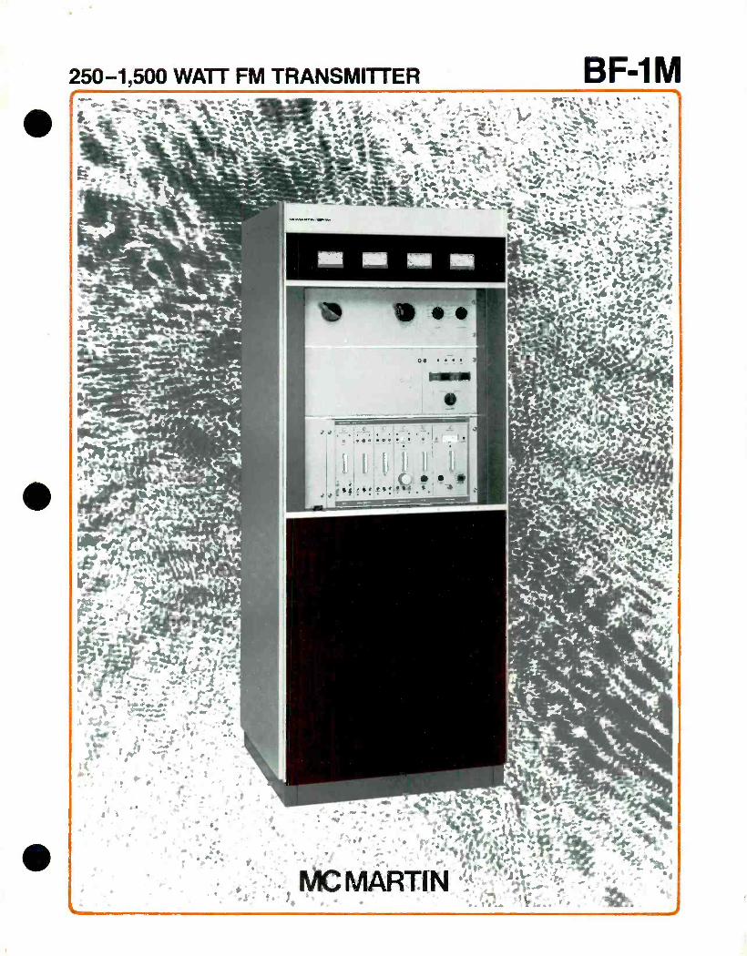
r I OPTIONAL I MAXI I
MONO AUDIO
STEREO GENERATOR
SCA GENERATOR
RF EXCITER BFM -I5
2 - 15W
PHASE LOCK a
REF.
SOLID STATE IPA AMPLIFIER
100W
POWER SUPPLY a
ALARM
Block diagram
POWER AMP 3CXI500A7
RF OUT
PA
POWER SUPPLY
PLATE VOLTAGE METER
MULTIMETER
PA TUNE
PA LOAD STOP
BFM -15 EXCITER
CIRCUIT BREAKER
Front panel description
PLATE CURRENT METER
REFLECTSMETER MULTIMETER
REFLECTOMETER
STATUS INDICATORS PLATE ON
PLATE OFF
START
POWER OUTPUT
24 (60 96) DOOR
26 1/4" (66.62)
13" (33.02) DOOR
281/2" (72.4 )
DIMENSIONS IN ( )
GIVEN IN CENTIMETERS
J
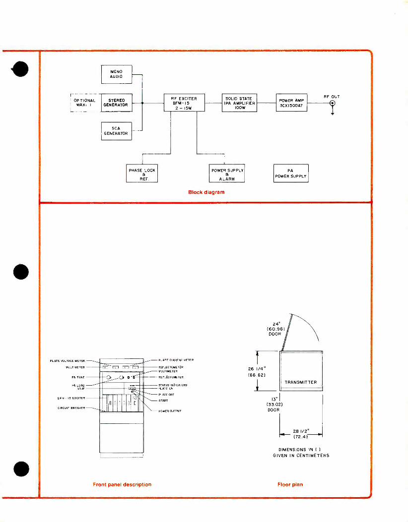
SPECIFICATIONS
OPERATING RANGE
RF POWER OUTPUT
RF OUTPUT IMPEDANCE
CENTER FREQUENCY STABILITY
MODULATION CAPABILITY
AUDIO INPUT IMPEDANCE
AUDIO INPUT LEVEL
AUDIO FREQUENCY RESPONSE
TOTAL HARMONIC DISTORTION
IM DISTORTION
FM NOISE
AM NOISE
POWER REQUIRED
POWER CONSUMPTION
OPERATING TEMPERATURE
ALTITUDE
DIMENSIONS
WEIGHT
FINISH
STEREO OPERATION (with
AUDIO INPUT IMPEDANCE
AUDIO INPUT LEVEL
AUDIO FREQUENCY RESPONSE
88 to 108 MegaHertz
1,500 watts maximum
50 ohms
500 Hz
+150 kHz
600 ohms, balanced
--10, ±2, dBm
+0.75 dB, 30-15,000 Hz (Std. FCC 75 usec preemphasis)
0.3% or less, 30- 15,000 Hz, 100% mod.
..0.2% or less 60 Hz /7 KHz, 4:1 ratio
.. >65 dB below 100% modulation (typical 70 dB)
>55 dB below carrier level
208/230/240 Vac. 50/60 Hz, single phase. 3 -wire.
1 500W output. 2,600W 1,000W output, 1,700W
250W output, 850W
0" to 50° Celsius
7.500 feet above mean sea level
width 281/4" (71.8 cm) height 701/2" (179 cm) depth 253/4" (65.4 cm) rear door swing 30" (76.2 cm)
actual 590 lbs (267.3 kg) crated 670 lbs (303.5 kg)
McMartin beige w -wood- grain trim
BFM -1521 Stereo Assembly)
600 ohms balanced, each channel
+10, 2, dBm
*0.75 dB. 30- 15,000 Hz. Std FCC 75 usec, preemphasis,
each channel
TOTAL HARMONIC DISTORTION 0 5 %or less, 30- 15,000 Hz
IM DISTORTION ..0.2% or less 60 Hz/7 KHz, 4:1 ratio
STEREO SEPARATION 40 dB or greater, 50- 15,000 Hz
typically 50 dB or greater at mid -range
FM NOISE 60 dB or greater below 100% modulation
PILOT STABILITY 4-1 0 Hertz over rated temperature range
SUBCARRIER SUPPRESSION 55 dB or :greater
CROSSTALK (L +R to L -R, L -R to L +R) 40 dB or greater below 90%
modulation
SCA OPERATION (with BFM -1531 SCA Generator Module)
AUDIO INPUT IMPEDANCE 600 ohms. ba anced
+10, ±2. dBm
CARRIER FREQUENCY 41 or 67 Khz standard
(others available on request)
CARRIER STABILITY -- O0 Hz
MODULATION CAPABILITY -7.5 kHz
PREEMPHASIS 150 usec standard, 50 or 75 usec available on request
FREQUENCY RESPONSE -1.5 dB, 50 -5000 Hz
CROSSTALK (main to sub, sub to main) 60 dB or lower
DISTORTION (50 -5000 Hz)
AUDIO INPUT LEVEL
0 75% or less with LP output filter
2.5 °ró or less with BP output filter S/N NOISE 60 dB or greater
ORDERING INFORMATION
Model Description Product Code BF -1M .25 -1.5KW FM broadcast
transmitter, complete with exciter and tubes, 208/230/240 VAC, 50/60 Hz, single phase 3 -wire (grounded neutral) 10 -01 -090
STF -1K Spare tube kit for BF -1M ..10 -01 -094 Spare rectifier diode stack RS 1.5- 12 -12M (Requires 2) 210015
McMartin Industries, Inc. 4500 South 76th Street Omaha, Nebraska 68127 Phone (402) 331 -2000 Telex 484485
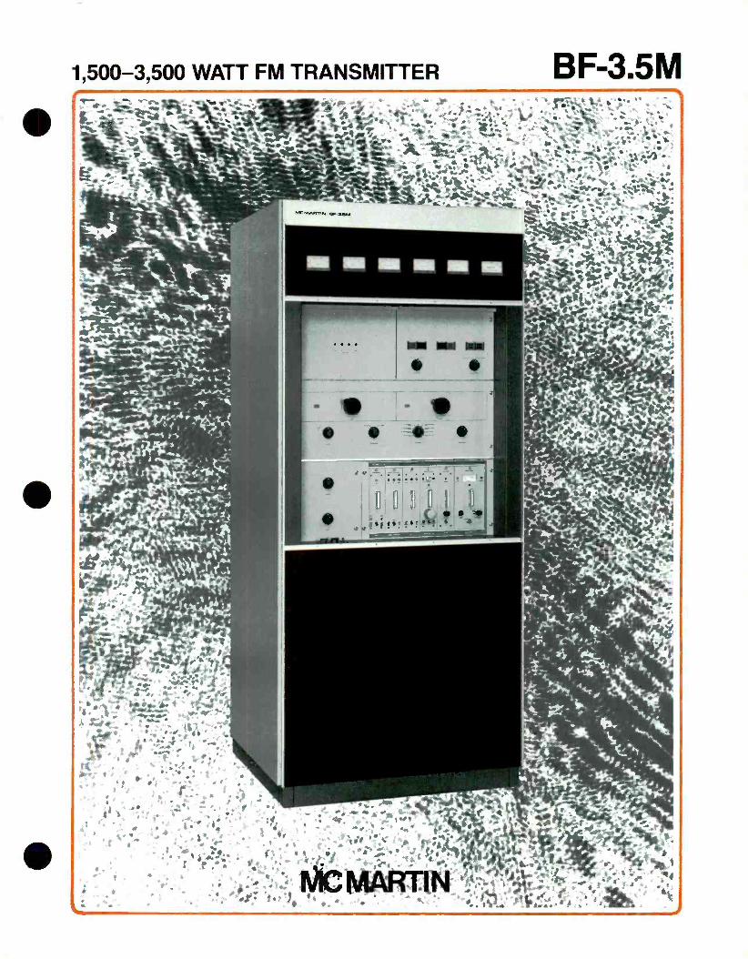
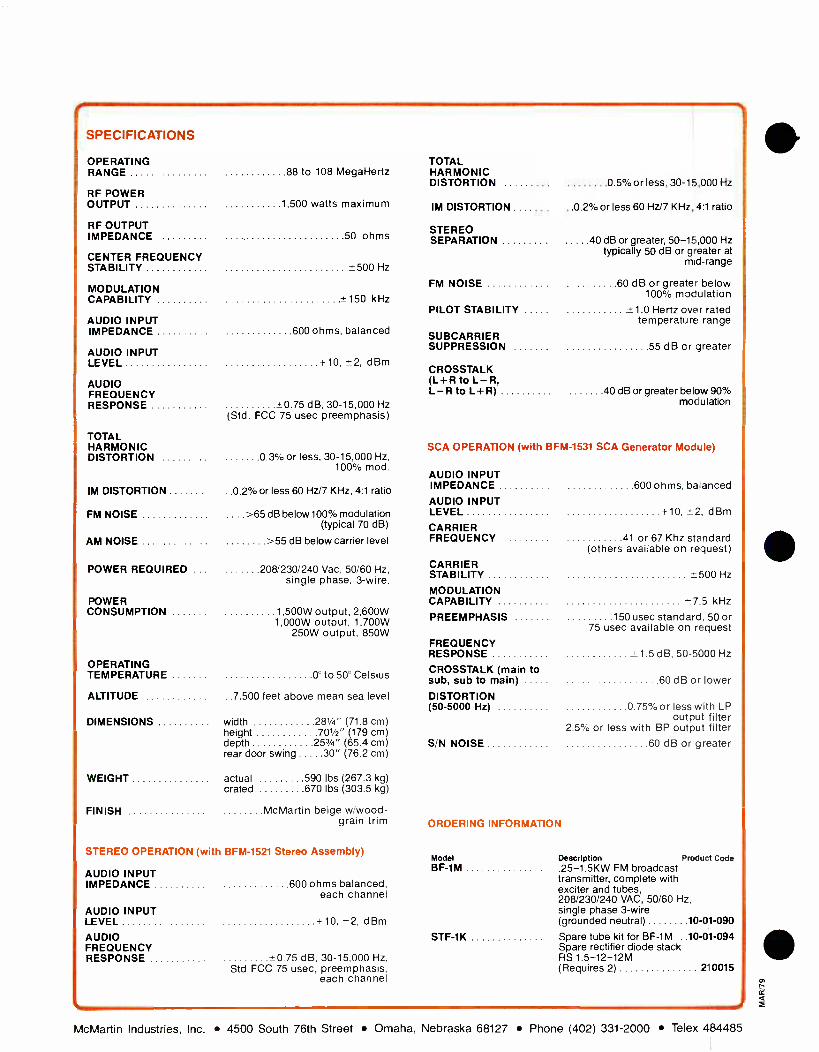
1,500-3,500 WATT FM TRANSMITTER - PA
`* d - ,
- 1*. 44^- - i 'A.. Pk,"
- '
MCMARTIN RAMER
BF-3.5M
_....- o . *"... ... , a s 0
-:' '..t -.. :.% - .-. . . t kt ,,,,`t -,' ...,:. ' , .-11* 1,, 1,,,, 41; . .. . .,,,.. 4 ; t t . , . .....,,N ,,. 1. poi o
O., ,,,44 7, .,aort : 10.. 1 ".... ...' . .. ". ".. 4 "7,..". 4"- If f .'. ' ' ° i.a, .% 04/* !--. ..- ' N w ¡.,:;r-..4 ' As
. 111 - Ole ,,,,, * .1,.., .. * * I` ,,, ,, k,,,ir ... .., or. 1,, ., ,,IIIKA.47;16 .1ritia 111.1 ..,,:1*, ,,,,, ,t, ..3,,,:, dr... , .. ., ii :.,_ '44 "., , ...- a *, , ,: , k ; .:: . .
' . .4k*/ ''.10; * ° - ' f* if ., I. 4,....t .;... t_..,/ ...I ; lc 4c. .1,,,,,,,,_ ...,,,, 4
...,1,:;;;:a9 IX' - -04,*1.1;W:4* ...,; i
' 7ke...". It > ,41or "ir
'4.6i,,,,,É4t14,ses, 1 0:41
61 /R ' e4;1414';;r41 9
.4Vig.
MI NIB 1111 IN MI MS
o a , ;
mar....41";ea: .. **PA ároirk 40! it
* n
* "3
°-
e -
:
1 41'1.; t * e á r
t" .
$ , N
I
I. .
I o
-
, . , it.' ,.
,t , "
** *
,
*
1., # .
0,,
It ,* 4* - 1... : *4. 1
4 '
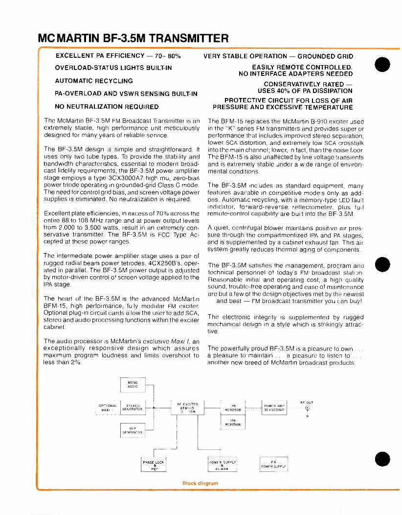
MC MARTIN BF -3.5M TRANSMITTER EXCELLENT PA EFFICIENCY - 70- 80%
OVERLOAD -STATUS LIGHTS BUILT -IN
AUTOMATIC RECYCLING
PA- OVERLOAD AND VSWR SENSING BUILT -IN
NO NEUTRALIZATION REQUIRED
The McMartin BF -3.5M FM Broadcast Transmitter is an extremely stable, high performance unit meticulously designed for many years of reliable service.
The BF -3.5M design is simple and straightforward. It
uses only two tube types. To provide the stability and bandwidth characteristics, essential to modern broad- cast fidelity requirements, the BF -3.5M power amplifier stage employs a type 3CX3000A7 high mu, zero -bias power triode operating in grounded -grid Class C mode. The need for control grid bias, and screen voltage power supplies is eliminated. No neutralization is required.
Excellent plate efficiencies, in excess of 70% across the entire 88 to 108 MHz range and at power output levels from 2,000 to 3,500 watts, result in an extremely con- servative transmitter. The BF -3.5M is FCC Type Ac- cepted at these power ranges.
The intermediate power amplifier stage uses a pair of rugged radial beam power tetrodes, 4CX250B's, oper- ated in parallel. The BF -3.5M power output is adjusted by motor -driven control of screen voltage applied to the IPA stage.
The heart of the BF -3.5M is the advanced McMartin BFM -15, high performance, fully modular FM exciter. Optional plug -in circuit cards allow the user to add SCA, stereo and audio processing functions within the exciter cabinet.
The audio processor is McMartin's exclusive Maxi-I, an exceptionally responsive design which assures maximum program loudness and limits overshoot to less than 2 %.
MONO AUDIO
OPTIONAL I MAXI I
STEREO GENERATOR
VERY STABLE OPERATION - GROUNDED GRID
SCA GENERATOR
RF EXCITER BFM -15 2 - 15W
EASILY REMOTE CONTROLLED. NO INTERFACE ADAPTERS NEEDED
CONSERVATIVELY RATED - USES 40 OF PA DISSIPATION
PROTECTIVE CIRCUIT FOR LOSS OF AIR PRESSURE AND EXCESSIVE TEMPERATURE
The BFM -15 replaces the McMartin B -910 exciter used in the "K" series FM transmitters and provides superior performance that includes improved stereo separation, lower SCA distortion, and extremely low SCA crosstalk into the main channel; lower, in fact, than the noise floor. The BFM -15 is also unaffected by line voltage transients and is extremely stable under a wide range of environ- mental conditions.
The BF -3.5M includes as standard equipment, many features available in competitive models only as add - ons. Automatic recycling, with a memory -type LED fault indicator, forward -reverse reflectometer, plus full remote -control capability are built into the BF -3.5M.
A quiet, centrifugal blower maintains positive air pres- sure through the compartmentized IPA and PA stages, and is supplemented by a cabinet exhaust fan. This air system greatly reduces thermal aging of components.
The BF -3.5M satisfies the management, program and technical personnel of today's FM broadcast station. Reasonable initial and operating cost, a high quality sound, trouble -free operating and ease of maintenance are but a few of the design objectives met by the newest - and best - FM broadcast transmitter you can buy!
The electronic integrity is supplemented by rugged mechanical design in a style which is strikingly attrac- tive.
The powerfully proud BF -3.5M is a pleasure to own . . .
a pleasure to maintain ... a pleasure to listen to . . .
another new breed of McMartin broadcast products.
PHASE LOCK a
REF.
1 P 4C 5250B
I PA
4CX25OB
POWER a
SUPPLY
ALARM
Block diagram
POWER AMP 3C X3000A7
PA POWER SUPPLY
RF OUT
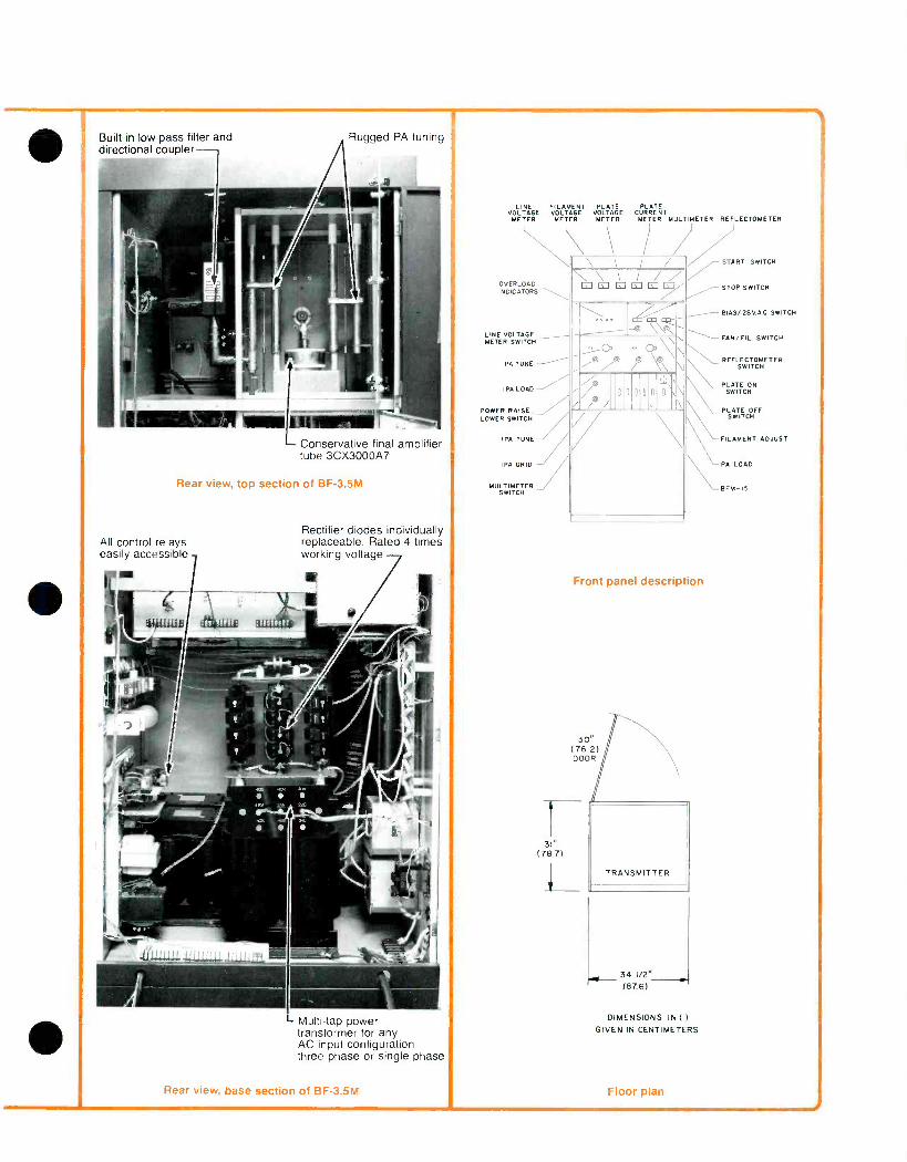
Built -in low pass filter and directional coupler
Rugged PA tuning I
Conservative final amplifier tube 3CX3000A7
Rear view, top section of BF -3.5M
All control relays easily accessible
Rectifier diodes individually replaceable. Rated 4 times working voltage
Multi -tap power transformer for any AC input configuration three phase or single phase
Rear view, base section of BF -3.5M
LINE FILAMENT PLATE PLATE VOLTAGE VOLTAGE VOLTAGE CURRENT METER METER METER METER MULTIMETER REFLECTOMETER
OVERLOAD
\ \ / / ( 0\ \ % ° a\\ A/ /e \\ \ / / / 0000n o\,\ \ \ \ \
N DIE ATORS
LINE VOLTAGE METER SWITCH
PA TUNE
IPA LOAD
POWER RAISE, LOWER SWITCH
IPA TUNE
IPA GRID
MULTIMETER SWITCH
START SWITCH
STOP SWITCH
BIAS/ 28VAC SWITCH
FAN /FIL. SWITCH
REFLECTOMETER SWITCH
PLATE ON SWITCH
PLATE O SWITCH
OFF
FILAMENT ADJUST
\PA LOAD
BFM -I5
Front panel description
30" (762) DOOR
31" (78.7)
TRANSMITTER
MIS 341/2" 11."
(87.6)
DIMENSIONS IN ( )
GIVEN IN CENTIMETERS
Floor plan
A
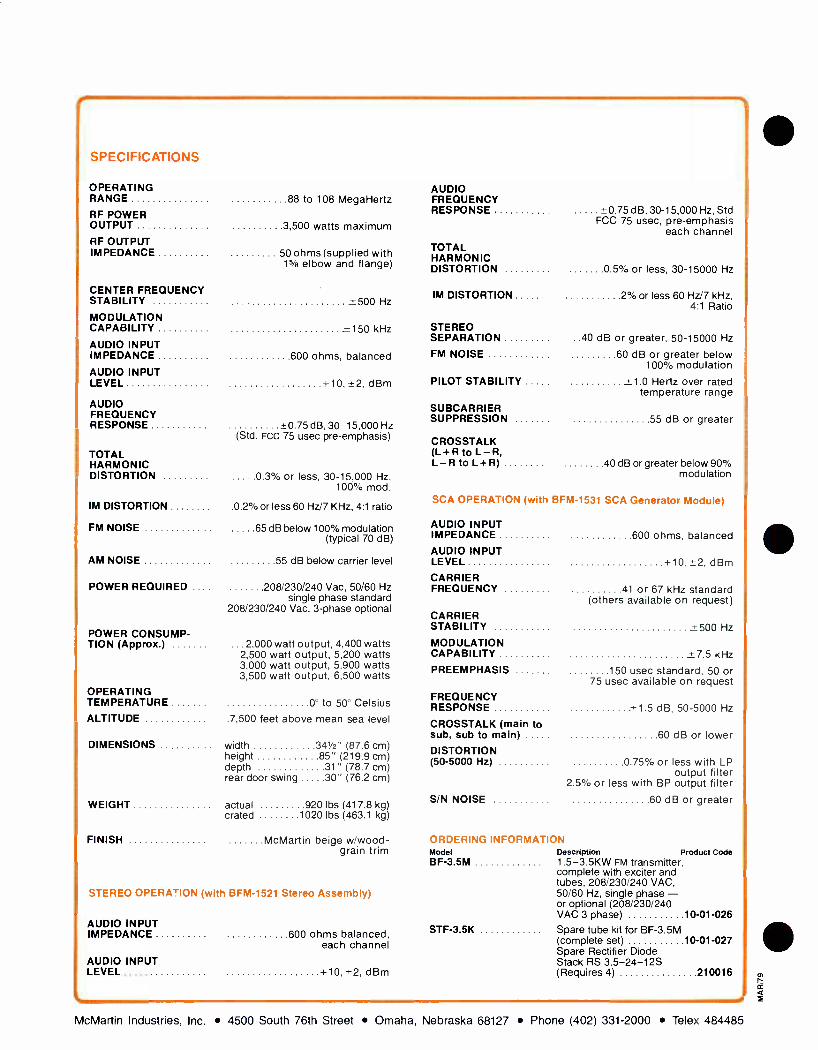
SPECIFICATIONS
OPERATING RANGE 88 to 108 MegaHertz
RF POWER OUTPUT
RF OUTPUT IMPEDANCE
CENTER FREQUENCY STABILITY
MODULATION CAPABILITY
3,500 watts maximum
50 ohms (supplied with 15 /e elbow and flange)
+500 Hz
+150 kHz
AUDIO INPUT IMPEDANCE 600 ohms, balanced
AUDIO INPUT LEVEL +10, ±2, dBm
AUDIO FREQUENCY RESPONSE ±0.75 dB, 30- 15,000 Hz
(Std. FCC 75 usec pre- emphasis)
TOTAL HARMONIC DISTORTION 0.3% or less, 30- 15,000 Hz,
100% mod.
IM DISTORTION .0.2% or less 60 Hz/7 KHz, 4:1 ratio
FM NOISE 65 dB below 100% modulation (typical 70 dB)
AM NOISE 55 dB below carrier level
POWER REQUIRED 208/230/240 Vac, 50/60 Hz single phase standard
208/230/240 Vac, 3 -phase optional
POWER CONSUMP- TION (Approx.) ... 2,000 watt output, 4,400 watts
2,500 watt output, 5,200 watts 3,000 watt output, 5,900 watts 3,500 watt output, 6,500 watts
OPERATING TEMPERATURE 0° to 50° Celsius ALTITUDE .7,500 feet above mean sea level
DIMENSIONS .. width 341/2" (87.6 cm) height 85" (219.9 cm) depth 31" (78.7 cm) rear door swing 30" (76.2 cm)
WEIGHT actual 920 lbs (417.8 kg) crated 1020 lbs (463.1 kg)
FINISH McMartin beige w /wood- grain trim
STEREO OPERATION (with BFM -1521 Stereo Assembly)
AUDIO INPUT IMPEDANCE 600 ohms balanced,
each channel
AUDIO INPUT LEVEL +10, +2, dBm
AUDIO FREQUENCY RESPONSE
TOTAL HARMONIC DISTORTION
IM DISTORTION
STEREO SEPARATION
FM NOISE
PILOT STABILITY
SUBCARRIER SUPPRESSION
CROSSTALK (L +R to L R, L R to L+R)
+0 75 d B, 30- 15.000 Hz, Std FCC 75 usec, pre- emphasis
each channel
0.5% or less, 30 -15000 Hz
2% or less 60 Hz/7 kHz, 4:1 Ratio
..40 dB or greater, 50 -15000 Hz
60 dB or greater below 100% modulation
+1 0 Hertz over rated temperature range
55 dB or greater
40 dB or greater below 90% modulation
SCA OPERATION (with BFM -1531 SCA Generator Module)
AUDIO INPUT IMPEDANCE
AUDIO INPUT LEVEL
CARRIER FREQUENCY
CARRIER STABILITY
MODULATION CAPABILITY
PREEMPHASIS
FREQUENCY RESPONSE
CROSSTALK (main to sub, sub to main)
DISTORTION (50 -5000 Hz)
S/N NOISE
600 ohms, balanced
+10, ±2, dBm
41 or 67 kHz standard (others available on request)
+500 Hz
+7 5 kHz
150 usec standard, 50 or 75 usec available on request
+1 5 dB, 50-5000 Hz
60 dB or lower
0.75% or less with LP output filter
2.5% or less with BP output filter 60 dB or greater
ORDERING INFORMATION Model Description Product Code BF -3.5M 1.5 -3.5KW FM transmitter,
complete with exciter and tubes, 208/230/240 VAC, 50/60 Hz, single phase - or optional (208/230/240 VAC 3 phase) 10 -01 -026
STF -3.5K Spare tube kit for BF -3.5M (complete set) 10 -01 -027 Spare Rectifier Diode Stack RS 3.5- 24 -12S (Requires 4) 210016
McMartin Industries, Inc. 4500 South 76th Street Omaha, Nebraska 68127 Phone (402) 331 -2000 Telex 484485
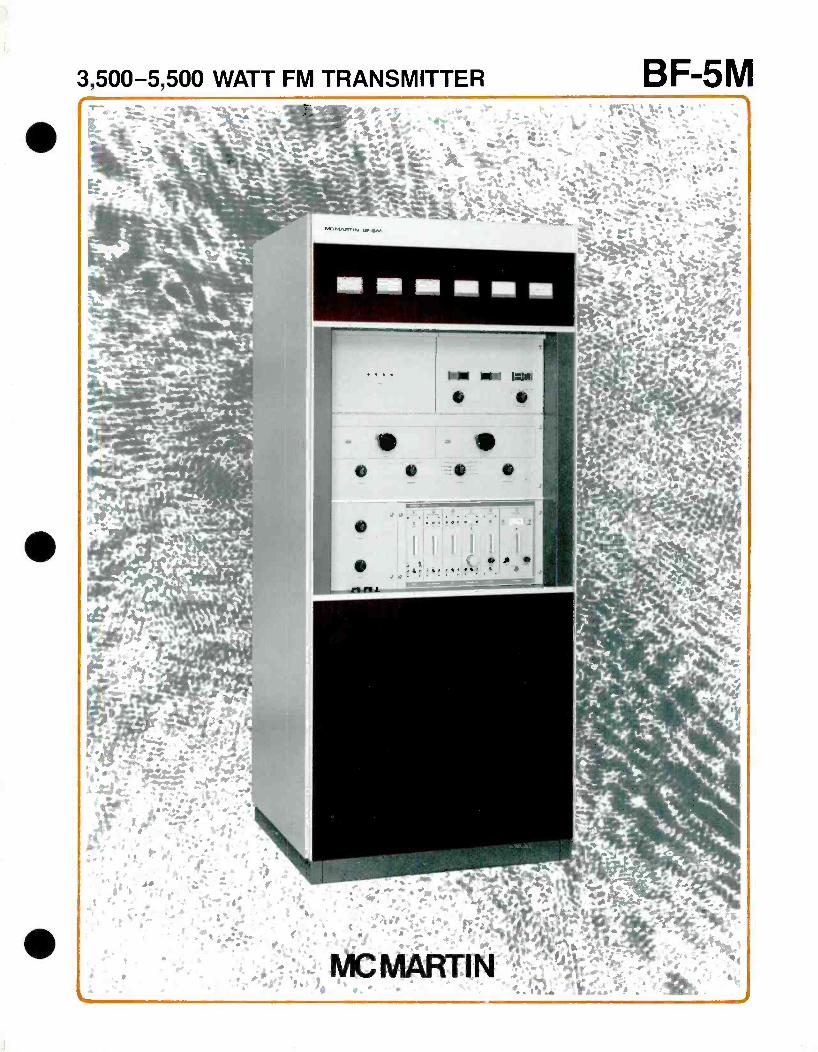
3,500-5,500 WATT FM TRANSMITTER BF-5M
MC MARTIN BF -5M TRANSMITTER
EXCELLENT PA EFFICIENCY - 70- 80%
OVERLOAD -STATUS LIGHTS BUILT -IN
AUTOMATIC RECYCLING
PA- OVERLOAD AND VSWR SENSING BUILT-IN
NO NEUTRALIZATION REQUIRED
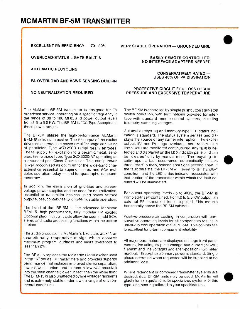
The McMartin BF -5M transmitter is designed for FM broadcast service, operating on a specific frequency in the range of 88 to 108 MHz, and power output levels from 3.5 to 5.5 KW. The BF -5M is FCC Type Accepted at these power ranges.
The BF -5M utilizes the high -performance McMartin BFM -15 solid state exciter. The RF output of the exciter drives an intermediate power amplifier stage consisting of paralleled Type 4CX250B radial beam tetrodes. These supply RF excitation to a ceramic /metal, zero - bias, hi -mu triode tube, Type 3CX3000 /A7 operating as a grounded -grid Class C amplifier. This configuration is well- recognized as optimum for the wide -band char- acteristics essential to superior stereo and SCA mul- tiplex operation today - and for quadraphonic sound, tomorrow.
In addition, the elimination of grid -bias and screen - voltage power supplies and the need for neutralization, essential to transmitter designs using power tetrode output tubes, contributes to long -term, stable operation.
The heart of the BF -5M is the advanced McMartin BFM -15, high performance, fully modular FM exciter. Optional plug -in circuit cards allow the user to add SCA, stereo and audio processing functions within the exciter cabinet.
The audio processor is McMartin's Exclusive Maxi-I, an exceptionally responsive design which assures maximum program loudness and limits overshoot to less than 2 %.
The BFM -15 replaces the McMartin B -910 exciter used in the "K" series FM transmitters and provides superior performance that includes improved stereo separation, lower SCA distortion, and extremely low SCA crosstalk into the main channel; lower, in fact, than the noise floor. The BFM -15 is also unaffected by line voltage transients and is extremely stable under a wide range of environ- mental conditions.
VERY STABLE OPERATION - GROUNDED GRID
EASILY REMOTE CONTROLLED. NO INTERFACE ADAPTERS NEEDED
CONSERVATIVELY RATED - USES 40% OF PA DISSIPATION
PROTECTIVE CIRCUIT FOR LOSS OF AIR PRESSURE AND EXCESSIVE TEMPERATURE
The BF -5M is controlled by simple pushbutton start -stop switch operation, with terminations provided for inter- face with standard remote control systems, including telemetry sampling voltages.
Automatic recycling and memory -type LED status indi- cation is standard. The status system senses and dis- plays the source of any carrier interruption. The exciter output; IPA and PA stage overloads; and transmission line VSWR are monitored continuously. Any fault is de- tected and displayed on the LED indicator panel and can be "cleared" only by manual reset. The recycling cir- cuitry upon a fault occurrence, automatically initiates three "start" pulses, spaced about one second apart. If
the fault persists, the BF -5M will revert to its "standby" condition, and the LED status indicator associated with that portion of the transmitter within which the fault oc- curred will be illuminated.
For output operating levels up to 4KW, the BF -5M is completely self- contained. For 4.0 to 5.5 KW output, an external RF harmonic filter is supplied. This mounts horizontally above the BF -5M cabinet.
Positive -pressure air cooling, in conjunction with con- servative operating levels for all components results in unusually cool operation of the BF -5M. This contributes to excellent long -term component reliability.
All major parameters are displayed on large front panel meters, including PA plate voltage and current; VSWR; filament and line voltages and a ten -position multimeter readout. Three -phase primary power is standard. Single phase operation when requested will be suoplied at no additional cost.
Where redundant or combined transmitter systems are desired, dual BF -5M units may be used. McMartin will gladly furnish quotations for specialized systems of this type, engineering -tailored to your specifications.
MONO AUDIO
OPTIONAL MAXI I
L
STEREO GENERATOR
SCA GENERATOR
RF EXCITER BFM -I5 2 -15W
PHASE LOCK a
REF.
IPA 4CX250B
IPA 4CX2508
POWER a
SUPPLY
ALARM
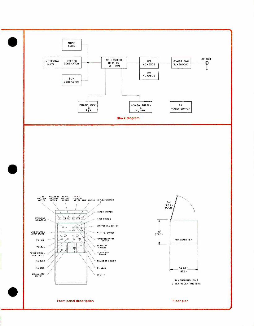
Block diagram
POWER AMP 3CX3000A7
PA POWER SUPPLY
RF OUT
T
LINE FILAMENT PLATE PLATE VOLTAGE VOLTAGE VOLTAGE CURRENT METER METER METER METER MULTIMETER REFLECTOMETER
OVERLOAD INDICATORS-\,,
LINE VOLTAGE METER SWITCH
PA TUNE
IPA LOAD
POWER RAISE, \ LOWER SWITCH /
IPA TUNE /J // IPA GRID J ///
MULTIMETER SWITCH
\ \ / / G71LI iiiO\ \-// %0, e Co \\ ,A7© 7 \\ \
® - i i / ou Iii'.
oo o' o\,\ I \ \ \
START SWITCH
STOP SWITCH
BIAS /2BVAC SWITCH
FAN /FIL SWITCH
\ REFLECTOMETER SWITCH
PLATE ON SWITCH
PLATE OFF SWITCH
FILAMENT ADJUST
\PA LOAD
BFM- 15
Front panel description
3" (78.7)
34 1/2° (876)
DIMENSIONS IN (
GIVEN IN CENTIMETERS
Floor plan
SPECIFICATIONS
OPERATING RANGE
RF POWER OUTPUT
RF OUTPUT IMPEDANCE
CENTER FREQUENCY STABILITY
MODULATION CAPABILITY
AUDIO INPUT IMPEDANCE
AUDIO INPUT LEVEL
AUDIO FREQUENCY RESPONSE
TOTAL HARMONIC DISTORTION
IM DISTORTION
FM NOISE
AM NOISE
POWER REQUIRED . .
POWER CONSUMP- TION (Approx.)
OPERATING TEMPERATURE
ALTITUDE
DIMENSIONS
WEIGHT
FINISH
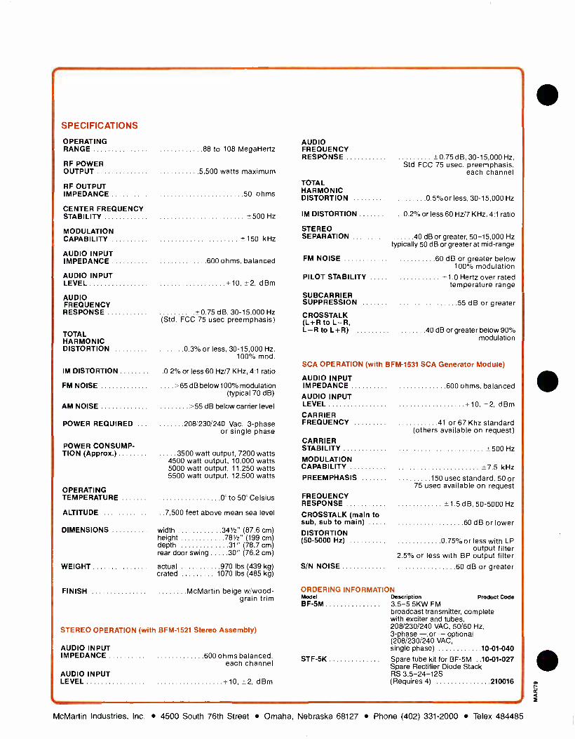
88 to 108 MegaHertz
5 500 watts maximum
50 ohms
*500 Hz
150 kHz
600 ohms, balanced
10. ±2, dBm
0.75 dB, 30-15.000 Hz (Std. FCC 75 usec preemphasis)
0.3% or less, 30- 15,000 Hz. 100% mod.
.0.2% or less 60 Hz /7 KHz, 41 ratio
>65 dB below 100% modulation (typical 70 dB)
>55 dB below carrier level
208/230/240 Vac, 3 -phase or single phase
3500 watt output, 7200 watts 4500 watt output, 10,000 watts 5000 watt output, 11,250 watts 5500 watt output, 12,500 watts
0° to 50° Celsius
.7,500 feet above mean sea level
width ..341/2" (87.6 cm) height ...781/2" (199 cm) depth 31" (78.7 cm) rear door swing . 30" (76.2 cm)
actual 970 lbs 439 kg crated 1070 lbs 485 kg
McMartin beige w /wood- grain trim
STEREO OPERATION (with BFM -1521 Stereo Assembly)
AUDIO INPUT IMPEDANCE
AUDIO INPUT LEVEL
600 ohms balanced. each channel
+10, dBm
AUDIO FREQUENCY RESPONSE -0.75 dB. 30- 15,000 Hz,
Std FCC 75 usec, preemphasis, each channel
TOTAL HARMONIC DISTORTION 0 5% or less, 30- 15.000 Hz
IM DISTORTION .0.2% or less 60 Hz /7 KHz, 4:1 ratio
STEREO SEPARATION 40 dB or greater, 50 -1 5,000 Hz
typically 50 dB or greater at mid -range
FM NOISE 60 dB or greater below 100% modulation
PILOT STABILITY +1.0 Hertz over rated temperature range
SUBCARRIER SUPPRESSION 55 dB or greater
CROSSTALK (L +R to L R, L R to L +R) 40 dB or greater below 90%
modulation
SCA OPERATION (with BFM -1531 SCA Generator Module)
AUDIO INPUT IMPEDANCE 600 ohms, balanced
+10, ±2, dBm
CARRIER FREQUENCY 41 or 67 Khz standard
(others available on request) CARRIER STABILITY *500 Hz
MODULATION CAPABILITY -p7 5 kHz
PREEMPHASIS 150 usec standard, 50 or 75 usec available on request
AUDIO INPUT LEVEL
FREQUENCY RESPONSE
CROSSTALK (main to sub, sub to main)
1 5 d B, 50-5000 Hz
60 dB or lower DISTORTION (50 -5000 Hz) 0 75% or less with LP
output filter 2.5% or less with BP output filter
S/N NOISE 60 dB or greater
ORDERING INFORMATION Model Description Product Code BF -5M 3.5 -5.5KW FM
broadcast transmitter, complete with exciter and tubes, 208/230/240 VAC, 50/60 Hz, 3 -phase -. or - optional (208/230/240 VAC, single phase) 10 -01 -040
STF -5K Spare tube kit for BF -5M ..10 -01 -027 Spare Rectifier Diode Stack RS 3.5- 24 -12S (Requires 4) 210016
i McMartin Industries, Inc. 4500 South 76th Street Omaha, Nebraska 68127 Phone (402) 331 -2000 Telex 484485
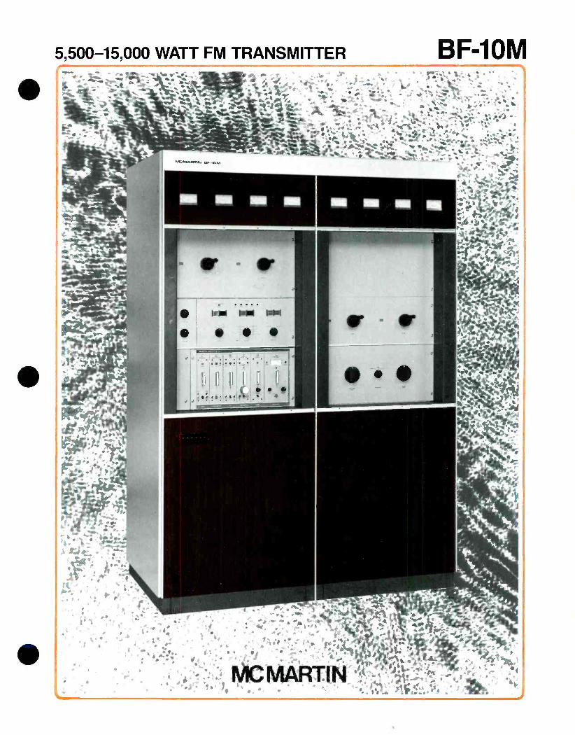
5,500-15,000 WATT FM TRANSMITTER BF-10M
MC MARTIN BF -10M TRANSMITTER
l EXCELLENT PA EFFICIENCY - 70 80%
OVERLOAD -STATUS LIGHTS BUILT-IN
AUTOMATIC RECYCLING
PA- OVERLOAD AND VSWR SENSING BUILT-IN
NO NEUTRALIZATION REQUIRED
For optimum performance and long -term reliability in FM broadcast installations requiring transmitter power out- put in the range of 5.5 to 15.0 kW, the McMartin Model BF -10M FM Broadcast Transmitter is the finest choice. The BF -10M is FCC Type Accepted at these power ranges.
The BF -10M meets todays stringent requirements for monaural, stereophonic and SCA multiplex operation - and is ready for the mode of tomorrow - quadraphonic sound.
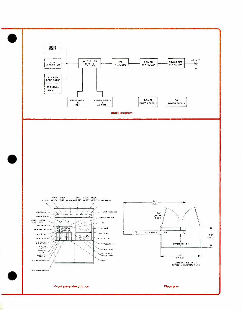
The excellent wideband characteristics of the BF -10M have been designed into the unit by the use of grounded -grid circuitry in its high -power RF driver and power amplifier stages. Both stages use ceramic /metal, zero -bias, high -mu triodes; a Type 3CX1500/A7 for the driver and a Type 3CX10,000 /A7 in the PA stage. Widely- recognized for their broadband characteristics in the grounded grid configuration, the use of these tube types also eliminates the need for neutralization and the many components required for grid bias and screen voltage power supplies. This results in an outstandingly simple and straightforward design approach in the criti- cal high -power RF stages.
One additional tube, a Type 4CX250B serves as an intermediate power amplifier between the solid -state BFM -15 exciter and the driver stage. Motor -driven screen voltage adjustment of the 4CX250B screen grid voltage insures extremely smooth control of the BF -10M power output level.
The heart of the BF -10M is the advanced McMartin BFM -15, high performance, fully modular FM exciter. Optional plug -in circuit cards allow the user to add SCA, stereo and audio processing functions within the exciter cabinet.
The audio processor is McMartin's Exclusive Maxi-I, an exceptionally responsive design which assures maximum program loudness and limits overshoot to less than 2 %.
The BFM -15 replaces the McMartin B -910 exciter used in the "K" series FM transmitters and provides superior performance that includes improved stereo separation,
llower SCA distortion, and extremely low SCA crosstalk
VERY STABLE OPERATION - GROUNDED GRID
EASILY REMOTE CONTROLLED. NO INTERFACE ADAPTERS NEEDED
CONSERVATIVELY RATED - USES 40% OF PA DISSIPATION
PROTECTIVE CIRCUIT FOR LOSS OF AIR PRESSURE AND EXCESSIVE TEMPERATURE
into the main channel; lower, in fact, than the noise floor. The BFM -15 is also unaffected by line voltage transients and is extremely stable under a wide range of environ- mental conditions.
The BF -10M is controlled by simple push- button start- stop switching, with terminations for remote control op- eration, including telemetry sampling voltages, for inter- face with all standard remote control systems.
Automatic recycling and memory-type LED status indi- cation is standard. The latter system senses and dis- plays the source of any carrier interruption. The exciter RF output; IPA, driver and PA stage overloads; and transmission line VSWR are continuously monitored. Any fault is detected and displayed on the LED indicator panel and can be "cleared" only by manual reset. The recycling circuitry automatically revert to a standby con- dition, and the LED status indicator for that portion of the transmitter in which the fault occurred will be illumi- nated.
The BF -10M is completely self- contained in an attractively -styled dual- section cabinet, with the excep- tion of the RF harmonic filter which is externally mounted above the BF -10M cabinet.
Positive pressure air cooling, in conjunction with con- servative operation of the high -power RF stages results in unusually cool operation of the BF -10M. This contrib- utes to excellent long -term component reliability.
All major parameters are monitored on large -size front panel meters. Driver and PA plate voltages and currents are metered separately. In addition VSWR, input line voltages, driver /PA filament voltages and a ten -position multimeter readout occupy the upper front meter panel.
The electrical and mechanical design of the BF -10M provides for easy field installation of optional power output feed at an approximately 1000 watt level directly from the 3CX1500/A7 driver stage.
Dual BF -10M units may be combined for redundant 10 to 13.5 KW, or combined 20 to 27 KW output opera- tion. McMartin will gladly furnish quotations for special systems of this type, engineered and tailored to your specifications.
MONO AUDIO
SCA GENERATOR
RF EXCITER BFM -I5
IPA 4Cx2508
DRIVER POWER AMP 3CX1500A7 3CX1000047
2 -15W
STEREO GENERATOR
OPTIONAL MAXI I
PHASE LOCK a
POWER SUPPLY a
DRIVER POWER SUPPLY
PA
POWER SUPPLY REF ALARM
Block diagram
RF OUT
T
DRIVER DRIVER LINE PLATE PLATE PLATE PLATE VOLTAGE VOLTAGE CURRENT
FILAMENT VOLTAGE CURRENT MULTIMETER METER METER METER REFLECTOMETER
\ \ , G7 Eí .4 Ea7 Ea7 i- a --1.-,970 --1.-,970 /O JO
®®-_ -, i/ ,// ,//
Óúllío
/ .\ I
í \ DRIVER LOAD ¡ STATUS INDICATORS
DRIVER TUNE
FLIVVRT POWER AMP FIL VOLT SWITCH
START SWITCH
IPA PLATE TUNE
IPA GRID TUNE
STOP SWITCH
NE VOLTAGE METER SWITCH
PLATE ON SWITCH
PSWÌT CHT
MULTIMETER / SWITCH
CIRCUIT BREAKERS
HIGH POWER SWITCH
Front panel description
-READY INDICATOR - AIR
PA TUNE
_- PA LOAD _ PA FIL. ADJ
REFLECTOSSETER SWITCH
DRIVER FIL. ADJ.
POWER RAISE, LOWER SWITCH
NNNI- BEM -IS
-46 BIN
(2057)
56° (142.2)
DIMENSIONS IN ( )
GIVEN IN CENTIMETERS
Floor plan
T 30"
(76.2)
l
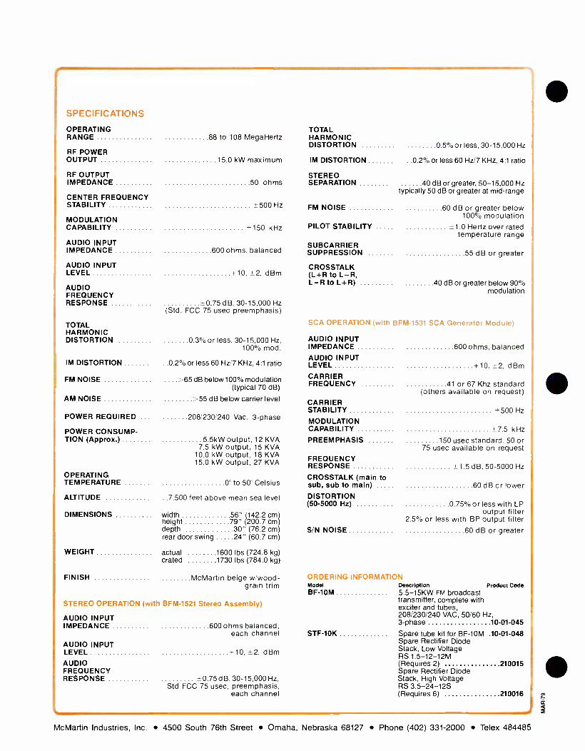
SPECIFICATIONS
OPERATING RANGE 88 to 108 MegaHertz
RF POWER OUTPUT 15.0 kW maximum
RF OUTPUT IMPEDANCE 50 ohms
CENTER FREQUENCY STABILITY *500 Hz
MODULATION CAPABILITY 150 kHz
AUDIO INPUT IMPEDANCE 600 ohms, balanced
AUDIO INPUT LEVEL +10, t2, dBm
AUDIO FREQUENCY RESPONSE -0.75 dB, 30-15,000 Hz
(Std. FCC 75 usec preemphasis)
TOTAL HARMONIC DISTORTION 0.3% or less, 30- 15.000 Hz,
100% mod.
IM DISTORTION ..0.2% or less 60 Hz /7 KHz, 4:1 ratio
FM NOISE . -65 dB below 100% modulation (typical 70 dB)
AM NOISE :-55 dB below carrier level
POWER REQUIRED .. 208/230/240 Vac, 3 -phase
POWER CONSUMP- TION (Approx.) 5 5kW output, 12 KVA
7.5 kW output, 15 KVA 10.0 kW output, 18 KVA 15.0 kW output, 27 KVA
OPERATING TEMPERATURE 0 to 50 Celsius
ALTITUDE .7.500 feet above mean sea level
DIMENSIONS width 56" 142.2 cm height ....79" 200.7 cm) depth 30" (76.2 cm) rear door swing 24" (60.7 cm)
WEIGHT actual 1600 lbs (724.8 kg) crated 1730 lbs (784.0 kg)
FINISH McMartin beige w /wood- grain trim
STEREO OPERATION (with BFM -1521 Stereo Assembly)
AUDIO INPUT IMPEDANCE 600 ohms balanced,
each channel AUDIO INPUT LEVEL +10. t2.dBm AUDIO FREQUENCY RESPONSE - 0.75 dB. 30- 15,000 Hz.
Std FCC 75 usec, preemphasis, each channel
TOTAL HARMONIC DISTORTION 0 5 %or less, 30- 15.000 Hz
IM DISTORTION ..0.2% or less 60 Hz /7 KHz, 4:1 ratio
STEREO SEPARATION 40 dB or greater, 50- 15,000 Hz
typically 50 dB or greater at mid -range
FM NOISE 60 dB or greater below 100% modulation
PILOT STABILITY - 1 0 Hertz over rated temperature range
SUBCARRIER SUPPRESSION 55 dB or greater
CROSSTALK (L +R to L -R, L -R to L +R) 40 dB or greater below 90%
modulation
OPERATION (with BFM -1531 SCA Generator Module)
AUDIO INPUT IMPEDANCE 600 ohms. balanced AUDIO INPUT LEVEL -r 10. i-2, dBm CARRIER FREQUENCY 41 or 67 Khz standard
(others available on request) CARRIER STABILITY -500 Hz
MODULATION CAPABILITY *7.5 kHz
PREEMPHASIS 150 usec standard. 50 or 75 usec available on request
FREQUENCY RESPONSE 1 5 dB, 50 -5000 Hz
CROSSTALK (main to sub, sub to main) 60 dB cr lower DISTORTION (50 -5000 Hz) 0 75% or less with LP
output filter 2.5% or less with BP output filter
S/N NOISE 60 dB or greater
ORDERING INFORMATION Model Description Product Code BF -10M 5.5 -15KW FM broadcast
transmitter, complete with exciter and tubes, 208/230/240 VAC, 50/60 Hz, 3 -phase 10 -01 -045
STF -10K Spare tube kit for BF -10M .10 -01 -048 Spare Rectifier Diode Stack, Low Voltage RS 1.5- 12 -12M (Requires 2) 210015 Spare Rectifier Diode Stack, High Voltage RS 3.5- 24 -12S (Requires 6) 210016
i McMartin Industries, Inc. 4500 South 76th Street Omaha, Nebraska 68127 Phone (402) 331 -2000 Telex 484485
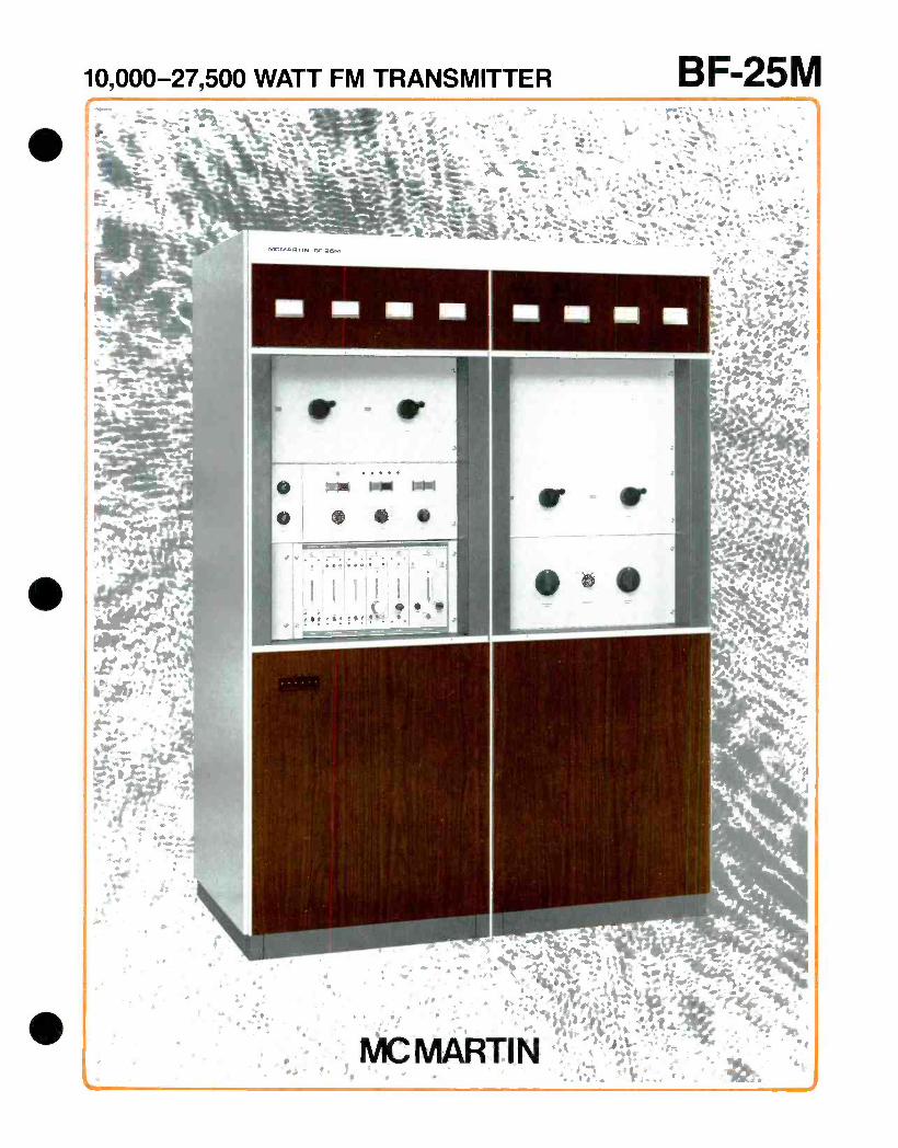
10,000- 27,500 WATT FM TRANSMITTER
.--: .,, ;, .. , :.- ,. s 14, ._
7i.:..40
.,..r. ti{a_Yi, 3 ^ t ' 1.'' * .!!s , ' 'c y .Z` . . . - `> ..:,sr e
f..i.y.¡ - i , 5 i . f * . . . }. . . a. `
`:;:- - , ..` . ,r-. ser r.. ;._. t.
4 ' ' .`
+ i ^y
i #14. ,,
.;,.. : , , .-
or
MC MARTIN BF -25M TRANSMITTER
EXCELLENT PA EFFICIENCY - 70 80%
OVERLOAD -STATUS LIGHTS BUILT-IN
AUTOMATIC RECYCLING
PA- OVERLOAD AND VSWR SENSING BUILT-IN
NO NEUTRALIZATION REQUIRED
The McMartin BF -25M FM broadcast transmitter satis- fies FM broadcast station installations requiring trans- mitter output levels from 10 to 27.5 kW. The BF -25M is FCC Type Accepted at these power ranges.
The BF -25M meets today's stringent requirements for stereo and SCA multiplex operation - and is ready for the mode of tomorrow, quadraphonic sound.
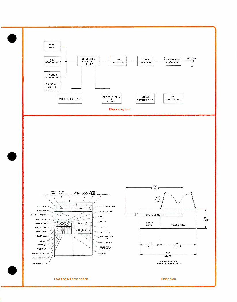
Selected for its widely recognized superior wide band characteristics, McMartin has incorporated grounded - grid Class C designs in the high -level driver and PA stages of the BF -25M. Both stages employ ceramic/ metal, zero /bias, high -mu triodes; a 3CX3000 /A7 for the driver and a 3CX20,000 /A7 in the power amplifier output stage. The latter tube, with rated 20,000 watt plate dissi- pation, when operated at the 27.5 KW maximum BF -25M output level utilizes less than 40% of its plate dissipation capability. This conservative operation is typ- ical of the overall design of the BF -25M. Emphasis has been placed on circuit simplicity, long -term reliability and ease of maintenance.
By the grounded -grid design approach, grid bias and screen -grid power supplies - essential to tetrode -tube type amplifiers, are completely eliminated. The some- times touchy and troublesome neutralization problems are gone. The BF -25M RF amplifier stages do not re- quire neutralization. The grounded -grid approach deliv- ers another little bonus. A portion of the "drive" power appears in the PA output circuit. This results in outstand- ing PA efficiency.
One additional tube, a Type 4CX250B, is used as the intermediate power amplifier between the solid -state exciter and the driver stage. Extremely smooth adjust- ment of the RF power output of the BF -25M is controlled by motor driven adjustment of the screen voltage applied to the 4CX250B tube.
The heart of the BF -25M is the advanced McMartin BFM -15, high performance, fully modular FM exciter. Optional plug -in circuit cards allow the user to add SCA, stereo and audio processing functions within the exciter cabinet.
The audio processor is McMartin's Exclusive Maxi-I, an exceptionally responsive design which assures maximum program loudness and limits overshoot to less than 2 %.
VERY STABLE OPERATION - GROUNDED GRID
EASILY REMOTE CONTROLLED. NO INTERFACE ADAPTERS NEEDED
CONSERVATIVELY RATEJ - USES 40% OF PA DISSIPATION
PROTECTIVE CIRCUIT FOR LOSS OF AIR PRESSURE AND EXCESSIVE TEMPERATURE
The BFM -15 replaces the McMartin B -910 exciter used in the "K" series FM transmitters and provides superior performance that includes improved stereo separation, lower SCA distortion, and extremely low SCA crosstalk into the main channel; lower, in fact, than the noise floor. The BFM -15 is also unaffected by line voltage transients and is extremely stable under a wide range of environ- mental conditions.
Interlocked control logic permits simple pushbutton switching of all start-stop functions. Termination for re- mote control operation, including telemetering sampling voltages, permit interface of the BF -25M with all stan- dard remote control systems.
Automatic recycling and a memory-type LED status in- dicator display, sense and indicate the source of carrier interruptions. The exciter output, IPA, driver and PA stages, high -voltage overload and VSWR are monitored continuously. Any fault is sensed and displayed on the LED indicator panel and can be cleared only by manual reset. The recycling circuitry automatically initiates three "start" pulses, spaced approximately one second apart. If the fault persists, the recycling detection circuit illuminates the LED, indicating that portion of the trans- mitter system where the fault occurred.
The BF -25M is housed in an attractively styled dual - section cabinet with the power amplifier stage occupy- ing one section and all other circuitry in the other. The two halves of the assembly are individually cooled. The electrical and mechanical design arrangement permits easy field installation of optional antenna transmission line switching to the output of the driver stage at a power level of approximately 2500 watts.
The high -voltage power transformer and associated silicon rectifier stacks for PA plate supply are housed in a separate assembly. The RF harmonic filter mounts hori- zontally above the main transmitter cabinet.
Driver and PA plate voltages and currents are separately metered. These parameters along with VSWR, line vol- tage, driver /PA filament voltages and a ten -position mul- timeter readout, are shown on the upper front -panel meter panel.
Dual BF -25M units are also available for redundant 27.5 or paralleled 55 KW output operation. McMartin would be pleased to furnish quotations on systems of this type, engineered and tailored to your specific situations.
MONO AUDIO
SCA GENERATOR
STEREO GENERATOR
OPTIONAL MAXI I
L - - -- - -
RF EXCITER BFM -15
2 -15W
PHASE LOCK d REF
IPA 4CX250B
POWER B
SUPPLY
ALARM
Block diagram
DRIVER 3CX3000A7
DRIVER
POWER SUPPLY
POWER AMP 3CX20000A7
PA
POWER SUPPLY
RF OUT
DRIVER DRIVER LINE PLATE PLATE PLATE PLATE VOLTAGE VOLTAGE CURRENT
FILAMENT VOLTAGE CURRENT MULTIMETER METER METER METER REFLECTOMETER
DRIVER- POWER HM VOLT SWITCH
START SWITCH
IPA PLATE TUNE
IPA GRID TUNE
STOP SWITCH
LINE VOLTAGE
ETER SWITCH
PLATE ON SWITCH
PLATE OFF J 9WITCM
MULTIMETER SWITCH
CIRCUIT BREAKERS
LOW POWER SWITCH
HIGH POWER SWITCH
I L o C ,I, C Z á 1 \^
l.Y ' /9/4/C
O_ D- fa.O o-_ \ 1110/1
iJ
/ óo I
Front panel description
STATUS INDICATORS
pEADY INDICATOR
MR
PA TIME
PA LOAD
PA FIL. ADJ
REFLECTOMET ER SWITCH
DRIVER FIL ADJ.
POWER RAISE, LOWER SWITCH
BEM- IS
120" (304.8)
POWER SUPPLY
30" (76.2)
30 woo 30"
(76.2)
.11 86"
56" (142 2 )
(218.4)
DIMENSIONS IN ( 1
GIVEN IN CENTIMETERS
Floor plan
fr
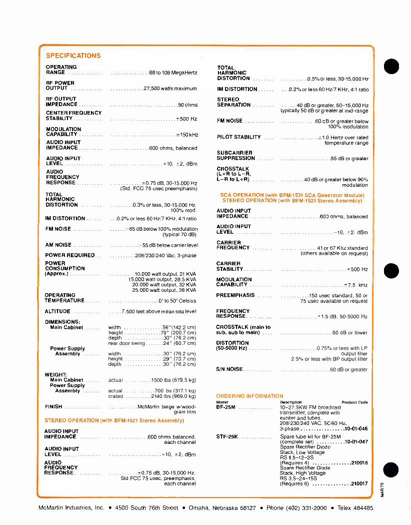
r SPECIFICATIONS
OPERATING RANGE
RF POWER OUTPUT
RF OUTPUT IMPEDANCE
CENTER FREQUENCY STABILITY
MODULATION CAPABILITY
AUDIO INPUT IMPEDANCE
AUDIO INPUT LEVEL
AUDIO FREQUENCY RESPONSE
TOTAL HARMONIC DISTORTION
IM DISTORTION
FM NOISE
AM NOISE
POWER REQUIRED
POWER CONSUMPTION (Approx.)
OPERATING TEMPERATURE
ALTITUDE
DIMENSIONS: Main Cabinet
Power Supply Assembly
WEIGHT: Main Cabinet Power Supply
Assembly
88 to 108 MegaHertz
27,500 watts maximum
50 ohms
*500 Hz
±150kHz
600 ohms, balanced
+10, ±2, dBm
*0.75 dB, 30-15,000 Hz (Std. FCC 75 usec preemphasis)
0 3% or less, 30- 15,000 Hz, 100% mod.
.0.2% or less 60 Hz /7 KHz, 4:1 ratio
>65 dB below 100 °ro modulation (typical 70 dB)
-55 dB below carrier level
208/230/240 Vac, 3 -phase
10,000 watt output, 21 KVA 15,000 watt output, 28.5 KVA
20.000 watt output, 32 KVA 25.000 watt output, 38 KVA
0° to 50° Celsius
7,500 feet above mean sea level
width 56 "(142.2 cm) height 79" (200.7 cm) depth 30" (76.2 cm) rear door swing 24" (60.7 cm)
width 30" (76.2 cm) height 29" (73.7 cm) depth 30" (76.2 cm)
actual 1500 lbs (679.5 kg)
actual 700 lbs (317.1 kg) crated 2140 lbs (969.0 kg)
FINISH McMartin beige w /wood- grain trim
STEREO OPERATION (with BFM -1521 Stereo Assembly)
AUDIO INPUT IMPEDANCE
AUDIO INPUT LEVEL
AUDIO FREQUENCY RESPONSE
600 ohms balanced, each channel
+10, *2, dBm
*0.75 dB, 30- 15,000 Hz, Std FCC 75 usec, preemphasis,
each channel
TOTAL HARMONIC DISTORTION
IM DISTORTION
STEREO SEPARATION
FM NOISE
PILOT STABILITY
SUBCARRIER SUPPRESSION
CROSSTALK (L+R to L-R, L-R to L+R)
0.5% or less, 30- 15,000 Hz
...0.2% or less 60 Hz /7 KHz, 4:1 ratio
40 dB or greater, 50- 15,000 Hz typically 50 dB or greater at mid -range
60 cB or greater below 100% modulation
*_ 1.0 Hertz over rated temperature range
55 dB or greater
40 dB or greater below 90% modulation
SCA OPERATION (with BFM -1531 SCA Generator Module) STEREO OPERATION (with BFM -1521 Stereo Assembly)
AUDIO INPUT IMPEDANCE
AUDIO INPUT LEVEL
CARRIER FREQUENCY
CARRIER STABILITY
MODULATION CAPABILITY
PREEMPHASIS
FREQUENCY RESPONSE
CROSSTALK (main to sub, sub to main) .. .
DISTORTION (50 -5000 Hz)
S/N NOISE
ORDERING INFORMATI Model BF -25M
STF-25K
600 ohms, balanced
-10, ±2, dBm
41 or 67 Khz standard (others available on request)
*500 Hz
*7.5 kHz
150 usec standard, 50 or 75 usec available on request
-1.5 dB, 50 -5000 Hz
60 dB or lower
0.75% or less with LP output filter
2.5% or less with BP output filter
60 dB or greater
ON Description Product Code 10- 27.5KW FM broadcast transmitter, complete with exciter and tubes, 208/230/240 VAC, 5C/60 Hz, 3 -phase 10 -01 -046
Spare tube kit for BF -25M (complete set) 10 -01 -047 Spare Rectifier Diode Stack, Low Voltage RS 1.5 -12 -2S (Requires 4) 210016 Spare Rectifier Diode Stack, High Voltage RS 3.5- 24 -15S (Requires 6) 210017
McMartin Industries, Inc. 4500 South 76th Street Omaha, Nebraska 68127 Phone (402) 331 -2000 Telex 484485
10,000 -55,000 WATT TRANSMITTER BF-55M a
"'": o<..
R
M, .
" Y- : +. ̂
' - ' '
!
4
i .
.
+
.
f .,. r
'
-
..
.
.
..t
. .. i v
v. /... ..lik,, Y .., \ A.',. /r f . . `` *IP ,1 0 ee.
1
.
,
.
s- 1 . " .*. w`., ̀ .. ..! : 'i J - !: ;1r ' t
c r r. r`} ... . s . {s
%MI E A :.: . ,.
1
s. t A r y
4 Z` s
,.,+r %
f 1 :4. l,tiá. ,'r a.. . ; , ' ` 9: ,M AS/F. r" . . i k- ll «I ,,. ̀ .,1 A ` " +, ̀ á .: .,, - % .
r dTv >«. ' `i.ÿf° i rl/.,/I t 3i,;; ̀ i "i. .
lt,_-*j*¡r 1 ». !
.;:._i.l..,..j i Mon:
VR.,,..
. .
%fa
K
9 ".
*NZ y r * , , '¡. s.s r
. ̀ j í,R~ , . . . ' ,M.ñ . ! . 44.'.oti::
. : . ' el .i i1 ,. + ... .1
.. +` , /. Á ,4"S i ri` `) y.t.e.. ,s : 'ti, I,
1 et ` l;-+ '
r ?-4 ' .Hp i.. : r . Yt!' i Iá ..... . } r`.rÌ
MC MARTIN 11.
1"l 'i,
f

MC MARTIN BF -55M TRANSMITTER
EXCELLENT PA EFFICIENCY - 70 80%
OVERLOAD -STATUS LIGHTS BUILT-IN
AUTOMATIC RECYCLING
PA- OVERLOAD AND VSWR SENSING BUILT-IN
NO NEUTRALIZATION REQUIRED
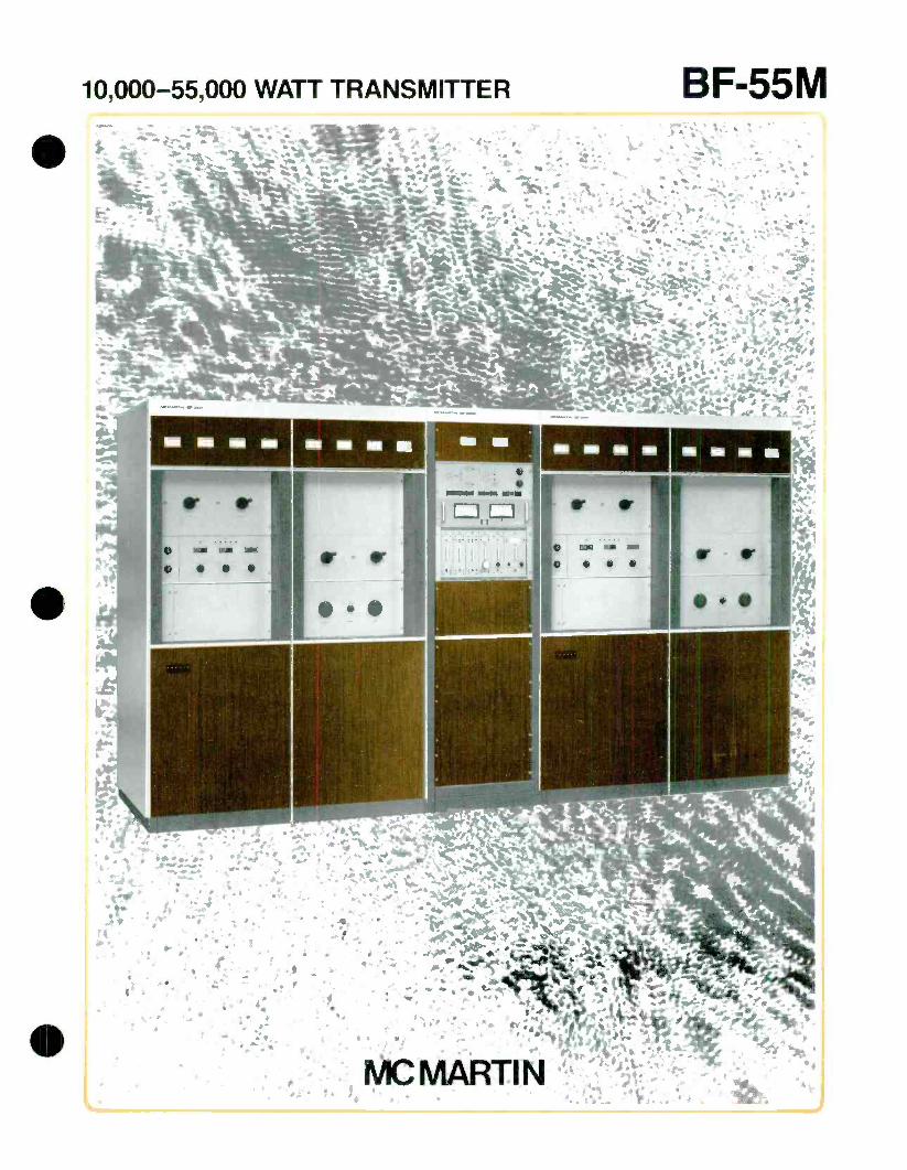
The McMartin Model BF -55M 55 KW FM Broadcast Transmitter consists of a single exciter which drives two identical 27.5 KW RF transmitter assemblies, the out- puts of which are combined to provide a single RF output termination delivering up to 55 kilowatts of power.
The 55- kilowatt output capability of the BF -55M has the advantage over competitive transmitters of 40 to 45 KW output capability, since the higher output power fre- quently permits the use of a less- complex, lower cost antenna array. This generally effects not only a lower investment in the antenna system itself but also lower total antenna windloading characteristics which are an important element in support tower costs.
In the event of a malfunction of one of the 27.5 KW RF
power units, transmission continues uninterrupted at a power level equal to one -quarter of the 55 KW output level, or 13,750 watts. An equivalent amount of power is dissipated in an air -cooled reject load.
The heart of the BF -55M is the advanced McMartin BFM -15, high performance, fully modular FM exciter. Optional plug -in circuit cards allow the user to add SCA, stereo and audio processing functions within the exciter cabinet.
The audio processor is McMartin's Exclusive Maxi-I, an exceptionally responsive design which assures maximum program loudness and limits overshoot to less than 2 %.
The BFM -15 replaces the McMartin B -910 exciter used in the "K" series FM transmitters and provides superior performance that includes improved stereo separation, lower SCA distortion, and extremely low SCA crosstalk into the main channel; lower, in fact, than the noise floor. The BFM -15 is also unaffected by line voltage transients
VERY STABLE OPERATION - GROUNDED GRID
EASILY REMOTE CONTROLLED. NO INTERFACE ADAPTERS NEEDED
CONSERVATIVELY RATED - USES 40% OF PA DISSIPATION
PROTECTIVE CIRCUIT FOR LOSS OF AIR PRESSURE AND EXCESSIVE TEMPERATURE
and is extremely stable under a wide range of environ- mental conditions.
The output of the exciter is fed to a power divider net- work to provide equal RF drive to each of the 27.5 KW RF power amplifier assemblies. These each are the McMar- tin Model BF -25M broadcast transmitter, less exciter. The control circuitry for these BF -25M units is such that intermediate power amplifier stages and the RF power amplifier stages and associated power supplies may be controlled independently. This greatly facilitates servic- ing and maintenance. The RF power assemblies are independently powered so that full redundancy is in- sured beyond the exciter portion of the system.
The individual RF power outputs feed low pass har- monic filters, the outputs of which are combined to pro- duce a single 61/8" EIA coaxial output termination.
There is considerable latitude in the physical configura- tion of the transmitter system which can be adapted to the most convenient arrangement for an individual transmitter plant installation. The equipment will be housed in the cabinetry used for two Model BF -25M units, plus an auxiliary matching cabinet enclosure which will house the output combiner control circuitry, exciter and reject load montoring panel. All coaxial line, fittings and associated hardware required to mechani- cally interconnect the harmonic filter, combining net- works, etc., are included.
The guaranteed electrical operating specifications, ex- cept for those obviously relating to power output, etc., for the McMartin Model BF -55M are identical to those shown for the individual McMartin Model BF -25M transmitters. The center combining cabinet incorporates the required control circuitry to operate either or both transmitters locally or by remote control.

OPTIONAL 1
MAXI I
BFM-I521 STEREO GEN
BFM-1531 SCA GEN.
BFM- 15
EXCITER SPLITTER
BF-25M°1 POWER STAGES
El POWER SUPPLY
HARMONIC FILTER MI
BF -25MM2 POWER STAGES -----
& POWER SUPPLY
Block diagram
HARMONIC FILTER 2
3 us" LINE
COMBINER
3 I /8 LINE
Q..
> OUM
CONTPBIUED T
LINE 55KW
V
20KW REJECT LOAD
30625" 171181
3" y ( 7621
34115" (ST 31)
56"
(192.201
2"
1552.88)
1530861
56" ((02.291
POWER SUPPLY
39.375"
(81.31)
DIMENSIONS IN ( 1
GIVEN IN CENTIMETERS
Floor plan
DRIVER L. PLATE PLA PLATE PLATE NOUN. VOL)). CURRENT RNRA MSON LIME VOLTAGE CURRENT MULTIMETER MR METER METER METER REFLECTOMETER REFLECTOMETER
DRIVER LOAD
FILAMENT READY INDOATOM -1 \`
DRIVER TUNE
STA US IN0IWTOR3 -\
DRIVER -POWER AMP FIL. VOLT SWITCH
START SWITCH
IPA PLATE TUNE
IPA GRID TUNE
STOP SWITCH
LINE VOLTAGE erER ewrtcH
PL TE ON BWITCK
PLABW8[74
MULTIIral
CIRCUIT BREAKERS
LOW POWER SWITCH
\\ \\\\ 11
I
d/ (/ s I °1 /. / ..>1 ® ®
o0000 0.-- ---9--4- 9%,7/f1
m m
/II I
o\cy® r c0000 //
I I I IPoOWÉR SMIT¿Ñ "%r-PcER
1 FP REFLECTOMETER PA FIL PA
LOAD SWITCH ADJUST TUNE
Front panel description
5 m9MTCM G N
ST 1,Y4 N9L1
TRAMWITTER CONTROL
SECOND BF14-15 ESCUTER WI AUTOMATE
TH
SWITCHING
(OPTIONAL)
- " -r:ATIONS
OPERATING RANGE 88 to 108 MegaHertz
RF POWER OUTPUT 55,000 watts maximum
RF OUTPUT IMPEDANCE 50 ohms
500 Hz CENTER FREQUENCY STABILITY
MODULATION CAPABILITY *150kHz
AUDIO INPUT IMPEDANCE 600 ohms, balanced
AUDIO INPUT LEVEL +10, +2, dBm
AUDIO FREQUENCY RESPONSE *_ 0.75 dBm, 30- 15,000 Hz (Std.
FCC 75 usec pre- emphasis) TOTAL HARMONIC DISTORTION 0 3% or less, 30- 15,000 Hz,
100% modulation
IM DISTORTION ...0.2% or less 60 Hz /7 KHz, 4:1 ratio
FM NOISE °65 dB below 100°4, modulation (typical 70 dB)
AM NOISE -55 dB below carrier level
POWER REQUIRED .. 208/230/240 Vac, 3 -phase
POWER CONSUMPTION (Approx.) 30,000 watt output, 54 KVA
40,000 watt output, 72 KVA 50,000 watt output, 90 KVA 55,000 watt output, 98 KVA
OPERATING TEMPERATURE 0° to 50- Celsius
ALTITUDE 7,500 feet above mean sea level
DIMENSIONS: Main Cabinet width 140 "(355.6 cm)
height 79" (200.7 cm) depth 30" (76.2 cm) rear door swing 24" (60.7 cm)
Power Supply Assembly (Two cabinets) ... width 30" (76.2 cm)
height 29" (73.7 cm) depth 30" (76.2 cm)
WEIGHT: Main Cabinet actual 2560 lbs (1160 kg)
crated 2760 lbs (1250 kg) Power Supply
Assemblies actual 1460 lbs (661 kg) crated 1540 lbs (698 kg)
Combiner actual 200 lbs (90 kg) crated 250 lbs (113 kg)
FINISH McMartin beige w /wood- grain trim
STFPFO OPERATION (with BFM -1521 Stereo Ass,-
AUDIO INPUT IMPEDANCE 600 ohms balanced,
each channel AUDIO INPUT LEVEL +10, 2, dBm
AUDIO FREQUENCY RESPONSE * -0.75 dB, 30- 15,000 Hz,
Std FCC 75 usec, preemphasis, each channel
TOTAL HARMONIC DISTORTION
IM DISTORTION
STEREO SEPARATION
FM NOISE
PILOT STABILITY ...
SUBCARRIER SUPPRESSION
CROSSTALK (L +R to L -R, L -R to L +R)
AUDIO INPUT IMPEDANCE
AUDIO INPUT LEVEL
CARRIER FREQUENCY
CARRIER STABILITY
MODULATION CAPABILITY
PREEMPHASIS
FREQUENCY RESPONSE
CROSSTALK (main to sub, sub to main) .. .
DISTORTION (50 -5000 Hz)
S/N NOISE
Model BF -55M
aL ACCESSORi AES
AOS
APC
AS-3
TCP-1
0 5 °ro or less 30- 15,000 Hz
2% or less 60 Hz /7 kHz, 4:1 Ratio
40 dB or greater, 50- 15,000 Hz typically 50 dB or greater at mid -range
60 dB or greater below 1006ó modulation
+1.0 Hertz over rated temperature range
55 dB or greater
40 dB or greater below 90% modulation
600 ohms, balanced
+10, +2, dBm
41 or 67 Khz standard (others available on request)
X500 Hz
+7.5 kHz
150 usec standard, 50 or 75 usec available on request
X1.5 dB, 50 -5000 Hz
60 dB or lower
0 75% or less with LP output filter
2.5 °ró or less with BP output filter
60 dB or greater
Description Product Code 30 -55KW FM broadcast transmitter, complete with one exciter (combined output of two BF -25M transmitters), 208/230/240 VAC, 50/60 Hz, 3 -phase 10 -01 -071
Automatic exciter switching for dual FM systems (provides complete exciter redundancy) 10 -01 -072
Automatic RF output switching for dual FM systems (first transmitter - to feed antenna and transmitter; second transmitter - to be fed to dummy load for maintenance) 10 -01 -073 Automatic power control for FM transmitter 10 -01 -074 Three phase AC detector with auto restart 10 -01 -075 Transmitter control panel for remote control for AM /FM transmitter 10 -01 -076
McMartin Industries, Inc. 4500 South 76th Street Omaha, Nebraska 68127 Phone (402) 331 -2000 Telex 484485
BFM -8000 fm exciter BFM -8000T 10 watt fm transmitter
BFM -8000 FM EXCITER BFM -8000T 10 WATT FM TRANSMITTER
DIRECT FM NO CRYSTAL OVEN
REMOTE CONTROL PROVISIONS SUPERIOR STEREO SEPARATION
SELF CONTAINED WITH INTERNAL POWER SUPPLY PHASE -LOCKED AFC PROVIDES ±500 Hz STABILITY
UNIT CAN BE USED AS EXCITER OR LOW POWER TRANSMITTER FULL METERING INCLUDING FORWARD POWER, REFLECTED POWER, AND MODULATION PERCENTAGE
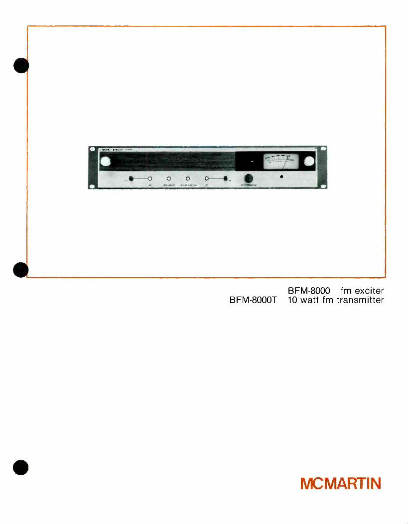
The McMartin BFM -8000 is designed to function either as an exciter for a higher power FM broadcast transmitter, or as a 10 -watt FM broadcast transmitter.
The BFM -8000 employs a unique C -MOS phase locked direct FM modulator. This provides ultra stable and precise frequency control.
All circuitry for the BFM -8000 FM Exciter/Transmitter is housed in a single drawer -type cabinet which pro- vides excellent accessibility for servicing and maintenance. Front panel metering of necessary operating parameters is provided. Monitoring and full remote control provisions are included.
The BFM -8000 also has been designed to provide the cleanest, most crisp sounding FM main channel signal and, when so equipped, multiplex stereo and SCA subchannel signals.
There are four units, each designed for rack mount- ing, for use with the BFM -8000 Exciter/Transmitter:
BFM-1531R SCA Generator BFM-1521R Stereo Generator
BFM -1514R "Maxi -1" Stereo Audio Processor BFM -1515R "Maxi -1" Monaural Audio Processor
The BFM-1521R Stereo Generator is equipped with 15 kHz input filters and a 53 kHz low -pass filter to assure that there is no interference with a 67 kHz SCA channel.
The BFM-1531R SCA Generators at 67 kHz are pro- vided with optimum filtering depending on whether they are used with monaural or stereo exciters. When utilized with a monuaral exciter, a 7.5 kHz band pass input filter is used; and a 90 kHz low pass output filter is used (this assures lowest distortion SCA and main channel reception). This filter combination assures the cleanest monaural and SCA signals, with objec-
tional interference and "birdies" totally eliminated. When a 67 kHz SCA Generator is used with an exciter equipped with a BFM-1521R Stereo Generator, the SCA generator's output filter is a 67 kHz band pass,thus assuring that no interference with the stereo (L -R) signal will occur.
The BFM-1531R SCA Generators at 41 kHz are equipped with 7.5 kHz input filters and a 60 kHz low pass output filter, which assures total non- interference with the main channel and the 67 kHz SCA channel.
BFM -1531 R SCA Generators are factory equipped for ±6 kHz deviation with the 7.5 kHz input filter. For ±4 kHz SCA deviation requirement, a 5 kHz input filter is optionally available.
This care in providing optimum filtering is just another example of the quality and care that comes with a BFM -8000, assuring clean signals with no possible subchannel to main channel interference.
PHASE LOCK DIRECT FM MODULATOR The heart of the BFM -8000 is the Direct FM modulator, with a phase lock AFC circuit providing ±500 Hz frequency stability. The frequency - modulated oscillator itself utilizes a free running oscillator at the operating frequency. This frequency is modulated by both the main and all sub -channel audio signals (stereo and/or SCA), and is buffered and amplified in the next stage. This on- carrier fre- quency signal is then digitally divided first by 11, then by 512, and compared in the phase /frequency corn - parator with a similarly divided signal from a highly stable temperature- compensated crystal oscillator. The phase comparator operates at about 20 kHz. Any phase difference detected between the two signals represents a frequency difference between the modulated oscillator and reference source and con-

sequently an off -frequency condition of the FMO. A correction voltage is then derived, which serves as an AFC voltage to maintain the FMO at its precise fre- quency.
A front panel LED indicator is provided to confirm proper phase lock. At the same time, FM power is automatically available from the output connector.
Special emphasis is placed on obtaining the highest possible degree of reliability while maintaining the performance characteristics equal to or better than competing equipment. As a result of this emphasis, our tentative failure analysis indicates a Mean Time Between Failure (MTBF) of nearly 1,000 hours, almost three times that of a typical competitive exciter, for a reliability of .990 (monaural operation).
EASE OF OPERATION AND MAINTENANCE
The BFM -8000 is designed for simple and easy opera- tion with operational controls held to a minimum.
Full front panel metering is provided to allow monitoring of operating voltages total modulation and other parameters.
Tuning the BFM -8000 is a very easy procedure and is accomplished in minutes utilizing the front panel meter to give an indication of a phase lock condition between the frequency modulated oscillator and the reference oscillator. Once phase lock is achieved,
Othe RF chain is optimized for maximum indication on the panel meter completing the tuning.
BFM -1521R STEREO GENERATOR The optional BFM-1521R Stereo Generator provides the 19 kHz pilot and the composite stereo signals (L + R and L - R). The stereo generator utilizes a switching mode oscillator employing a temperature stabilized crystal at four times the 19 kHz pilot fre- quency (76 kHz). This 76 kHz signal is digitally divided to derive the 19 kHz pilot and the 38 kHz square wave signal used to alternately switch between the left and right channel audio signals. The circuitry is precisely designed to assure that 38 kHz subcarrier suppression is 55 dB below the modulated signal. Use of the square wave switching mode eliminates the need for troublesome carrier balance adjust- ments. This simplifies adjustment, and additionally provides for excellent stereo separation (40 dB through the entire exciter or tranmsitter). Adjust- ments for the BFM-1521R Stereo Generator are held to a minimum. Only Pilot Level and Pilot Phase adjustments (for setting proper timing of the pilot and L -R signal) are provided on the front panel.
Local and remote stereo /mono mode switching are provided for with front panel indication of stereo operation. A remote indicator may be connected.
BFM -1514R AUDIO PROCESSOR
The BFM -1514R dual channel audio processor has
been designed to precisely control the modulation of the FM stereo or mono transmission system prevent- ing over -modulation with varying audio input levels.
Pre -emphasis may be switched in or out as desired. The processor is frequency conscious and follows the pre- emphasis curve, thereby assuring that the problems associated with pre- emphasis are con- trolled. This is accomplished by an extremely fast AGC circuit and not by diode clippers which produce undesired interference problems, especially in stereo transmissions. These circuits provide limiting of overshoot to 2 %.
Approximately 20 dB of gain reduction at low fre- quencies, and 30 dB gain reduction at high frequen- cies (pre- emphasis in), produce optimum compres- sion and gain reduction without the use of other signal processing devices.
A front panel release time control is adjustable in order to optimize the system for maximum loudness -using the fast setting (counterclockwise) - or for the best quality - using the slow setting (fully clockwise).
The recovery time will always be short for transients regardless of the setting of the control. Under sus- tained gain reduction, the recovery time will automatically lengthen depending on the program material content.
BFM -1515R MONAURAL PROCESSOR
The BFM -1515R Monaural Audio Processor is designed for use with a monaural main channel or for improving the loudness of an SCA channel. Its design and features are approximately the same as the BFM- 1514R.
BFM -1531R SCA GENERATOR
The BFM-1531R SCA Generator is optionally available to provide for a 67 kHz subchannel in an exciter equipped with a stereo generator. For use with a monaural exciter, either a 67 kHz and /or a 41
kHz SCA Generator is available (other frequencies 20 -75 kHz are available on special order).
The BFM-1531R is an ultra stable SCA generator utilizing a new internally compensated direct FM oscillator providing ultra stable operation even over widely varying temperature conditions. Manual or automatic SCA muting is provided and the mute cir- cuitry is adjustable, both for modulation level and delay time (which is continuously adjustable 1/2 to 8 seconds).
Unique to the BFM -1531R is the ability to remotely disable the automatic mute. This circuit provides a ready means of obtaining the necessary signal when making measurements at the studio requiring an unmodulated SCA subcarrier.
BFM-1531R SCA Generators are factory equipped for
±6 kHz deviation with a 7.5 input filter. For ±4 kHz SCA deviation requirement, a 5 kHz input filter is an option.
The BFM-1531R also has provision to allow the SCA subcarrier to be switched on and off locally and remotely.
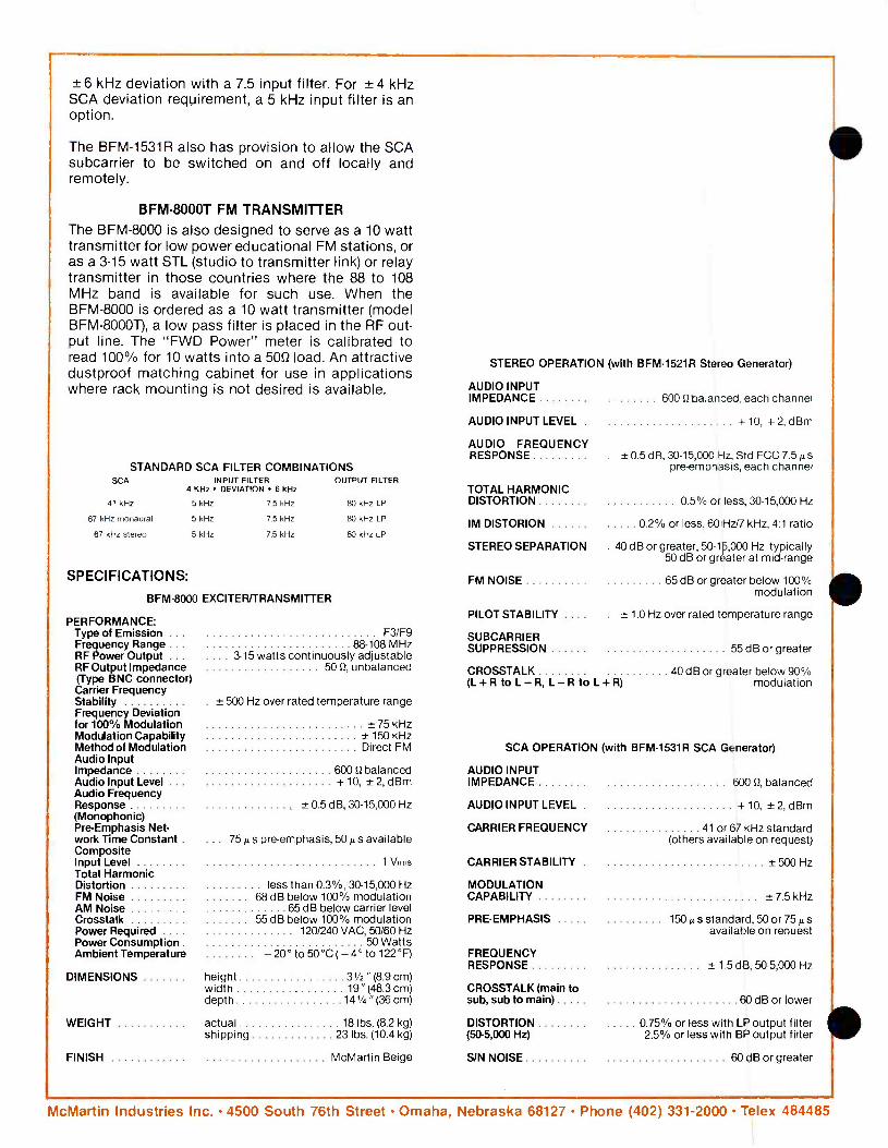
BFM -8000T FM TRANSMITTER The BFM -8000 is also designed to serve as a 10 watt transmitter for low power educational FM stations, or as a 3 -15 watt STL (studio to transmitter link) or relay transmitter in those countries where the 88 to 108 MHz band is available for such use. When the BFM -8000 is ordered as a 10 watt transmitter (model BFM- 80001), a low pass filter is placed in the RF out- put line. The "FWD Power" meter is calibrated to read 100% for 10 watts into a 5052 load. An attractive dustproof matching cabinet for use in applications where rack mounting is not desired is available.
STANDARD SCA FILTER COMBINATIONS SCA INPUT FILTER OUTPUT FILTER
4 KHz DEVIATION 6 kHz
5 kHz 7.5 kHz 80 kHz LP
5 kHz 7.5 kHz 80 kHz LP
5 kHz 7.5 kHz 80 kHz LP
41 kHz
67 kHz monaural
67 kHz stereo
SPECIFICATIONS:
BFM-8000 EXCITER/TRANSMITTER
PERFORMANCE: Type of Emission .. Frequency Range RF Power Output .. RF Output Impedance (Type BNC connector) Carrier Frequency Stability Frequency Deviation for 100% Modulation Modulation Capability Method of Modulation Audio Input Impedance Audio Input Level .. Audio Frequency Response (Monophonic) Pre -Emphasis Net- work Time Constant Composite Input Level Total Harmonic Distortion FM Noise AM Noise Crosstalk Power Required ... Power Consumption Ambient Temperature
DIMENSIONS
WEIGHT
FINISH
F3 /F9 88-108 MHz
... 3-15 watts continuously adjustable 50 0, unbalanced
± 500 Hz over rated temperature range
+75kHz + 150 kHz Direct FM
60012 balanced +10, ±2,dBm
±0.5 dB, 30-15,000 Hz
75 As pre -emphasis, 50 z s available
1 Vrms
less than 0.3 %, 30- 15,000 Hz 68 dB below 100% modulation
65 dB below carrier level 55 dB below 100% modulation
120/240 VAC, 50/60 Hz 50 Watts
- 20 °to50 °C(- 4 °to122 °F)
height 31/2 " (8.9 cm) width 19" (48.3 cm) depth 141/4 " (36 cm)
actual 18 lbs. (8.2 kg) shipping 23 lbs. (10.4 kg)
McMartin Beige
STEREO OPERATION (with BFM1521R Stereo Generator)
AUDIO INPUT IMPEDANCE 600 0 balanced, each channel
AUDIO INPUT LEVEL . + 10, +2, dBm
AUDIO FREQUENCY RESPONSE . ± 0.5 dB, 30- 15,000 Hz, Std FCC 7.5 A s
pre- emphasis, each channel
TOTAL HARMONIC DISTORTION 0.5% or less, 30- 15,000 Hz
IM DISTORION 0 2% or less, 60 Hz/7 kHz, 4:1 ratio
STEREO SEPARATION 40 dB or greater, 50- 15,000 Hz typically 50 dB or greater at mid -range
FM NOISE 65 dB or greater below 100% modulation
PILOT STABILITY .... ± 1.0 Hz over rated temperature range
SUBCARRIER SUPPRESSION 55 dB or greater
CROSSTALK 40 dB or greater below 90% modulation (L+R to L-R, L-R to L+R)
SCA OPERATION (with BFM-1531R SCA Generator)
AUDIO INPUT IMPEDANCE
AUDIO INPUT LEVEL
CARRIER FREQUENCY
CARRIER STABILITY
MODULATION CAPABILITY
600 0, balanced
+10, ±2,dBm
41 or 67 kHz standard (others available on request)
500 Hz
7.5 kHz
PRE -EMPHASIS 150 It s standard, 50 or 75 As available on request
FREQUENCY RESPONSE ± 1.5 dB, 50 -5,000 Hz
CROSSTALK (main to sub, sub to main) 60 dB or lower
DISTORTION 0 75% or less with LP output filter (50.5,000 Hz) 2.5% or less with BP output filter
S/N NOISE 60 dB or greater
McMartin Industries Inc. 4500 South 76th Street Omaha, Nebraska 68127 Phone (402) 331 -2000 Telex 484485
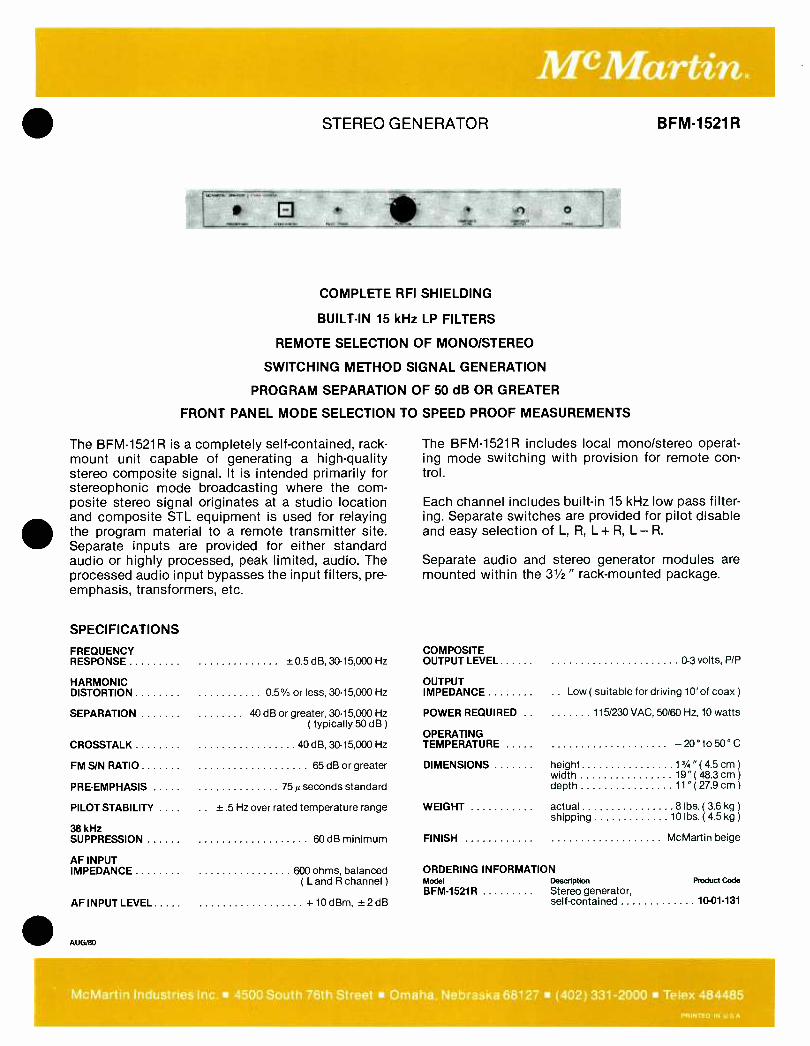
STEREO GENERATOR BFM-1521R
COMPLETE RH SHIELDING
BUILT -IN 15 kHz LP FILTERS
REMOTE SELECTION OF MONO /STEREO
SWITCHING METHOD SIGNAL GENERATION
PROGRAM SEPARATION OF 50 dB OR GREATER
FRONT PANEL MODE SELECTION TO SPEED PROOF MEASUREMENTS
The BFM-1521R is a completely self- contained, rack- The BFM-1521R includes local mono /stereo operat- mount unit capable of generating a high -quality ing mode switching with provision for remote con - stereo composite signal. It is intended primarily for trol. stereophonic mode broadcasting where the com- posite stereo signal originates at a studio location Each channel includes built -in 15 kHz low pass filter - and composite STL equipment is used for relaying ing. Separate switches are provided for pilot disable the program material to a remote transmitter site. and easy selection of L, R, L + R, L - R.
Separate inputs are provided for either standard audio or highly processed, peak limited, audio. The Separate audio and stereo generator modules are processed audio input bypasses the input filters, pre- mounted within the 31/2 " rack -mounted package. emphasis, transformers, etc.
SPECIFICATIONS
FREQUENCY COMPOSITE RESPONSE ± 0.5 dB, 30- 15,000 Hz OUTPUT LEVEL 0 -3 volts, P/P
HARMONIC OUTPUT DISTORTION 0.5% or less, 30- 15,000 Hz IMPEDANCE .. Low ( suitable for driving 10' of coax )
SEPARATION 40 dB or greater, 30- 15,000 Hz POWER REQUIRED .. 115/230 VAC, 50/60 Hz, 10 watts ( typically 50 dB )
OPERATING CROSSTALK 40 dB, 30- 15,000 Hz TEMPERATURE - 20 ° to 50° C
FM S/N RATIO 65 dB or greater DIMENSIONS height 13/4 " (4.5 cm )
width 19 "(48.3 cm) PRE -EMPHASIS 75 A seconds standard depth 11"( 27.9 cm)
PILOT STABILITY .. ±.5 Hz over rated temperature range WEIGHT actual 8 lbs. ( 3.6 kg )
shipping 10 lbs. (4.5 kg )
38 kHz SUPPRESSION 60 dB minimum FINISH McMartin beige
AF INPUT IMPEDANCE 600 ohms, balanced ORDERING INFORMATION
(L and R channel) Model Description Product code
AF INPUT LEVEL + 10 dBm, ±2 dB BFM -1521R Stereo generator,
self- contained 10-01-131
AUG/80
McMartin Industries Inc. 4500 South 76th Street Omaha, Nebraska 68127 (402) 331 -2000 Telex 484485 PRINTED IN U S A
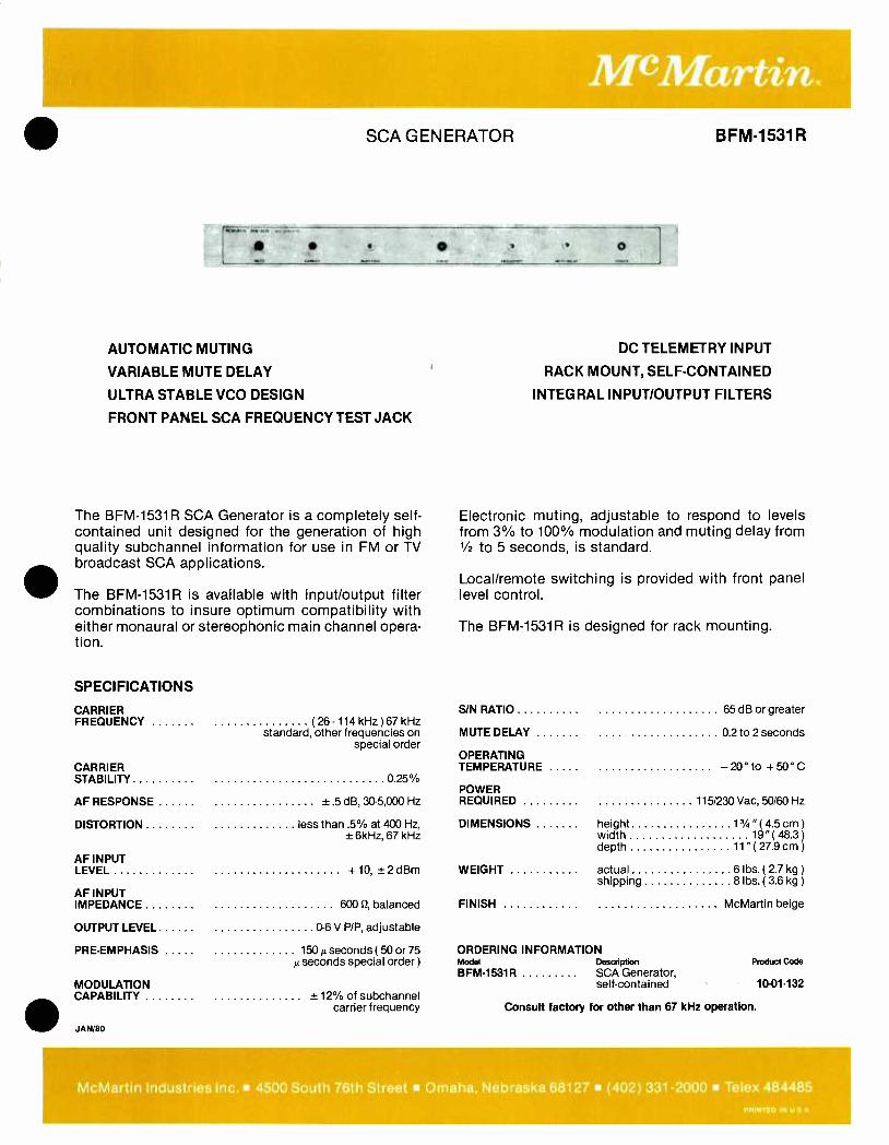
SCA GENERATOR BFM-1531R
o
AUTOMATIC MUTING
VARIABLE MUTE DELAY
ULTRA STABLE VCO DESIGN
FRONT PANEL SCA FREQUENCY TEST JACK
The BFM-1531R SCA Generator is a completely self - contained unit designed for the generation of high quality subchannel information for use in FM or TV broadcast SCA applications.
The BFM -1531R is available with input /output filter combinations to insure optimum compatibility with either monaural or stereophonic main channel opera- tion.
SPECIFICATIONS
CARRIER FREQUENCY (26 -114 kHz ) 67 kHz
standard, other frequencies on special order
CARRIER STABILITY 0 25%
AF RESPONSE ±.5 dB, 30 -5,000 Hz
DISTORTION less than .5% at 400 Hz, ± 6kHz, 67 kHz
AF INPUT LEVEL +10, ±2dBm
AF INPUT IMPEDANCE 600 0, balanced
OUTPUT LEVEL 0-6 V P /P, adjustable
PRE -EMPHASIS 150 µ seconds (50 or 75 µ seconds special order )
MODULATION CAPABILITY ±12c of subchannel
carrier frequency
JAN /80
DC TELEMETRY INPUT
RACK MOUNT, SELF -CONTAINED
INTEGRAL INPUT /OUTPUT FILTERS
Electronic muting, adjustable to respond to levels from 3% to 100% modulation and muting delay from 1/2 to 5 seconds, is standard.
Local /remote switching is provided with front panel level control.
The BFM-1531R is designed for rack mounting.
S/N RATIO 65 dB or greater
MUTE DELAY 0 2 to 2 seconds
OPERATING TEMPERATURE -20 °to +50°C
POWER REQUIRED 115/230 Vac, 50/60 Hz
DIMENSIONS height 13/4 " (4.5 cm )
width 19 "(48.3 )
depth 11 "(27.9 cm)
WEIGHT actual 6 lbs. (2.7 kg )
shipping 8 lbs. ( 3.6 kg )
FINISH McMartin beige
ORDERING INFORMATION Model Description
BFM-1531R SCA Generator, self -contained
Product Code
Consult factory for other than 67 kHz operation.
1001.132
McMartin Industries Inc. 4500 South 76th Street Omaha, Nebraska 68127 (402) 331 -2000 Telex 484485 PRINTED IN U S A

4
4
50 WATT FM AMPLIFIER
50 WATT FM TRANSMITTER
B -950 BFM -50
100 WATT FM AMPLIFIER
100 WATT FM TRANSMITTER
B-9100 BFM -100
r .. e jJ '
. . ¡ :, 04.ÿ^,r, 6 f rMi+ ..
..
Ì +& .*. *. Y.
° 'if'. _ .. , ..
` ..
.
s'
C
(J
C O ° o _..
MC MARTIN ..
,
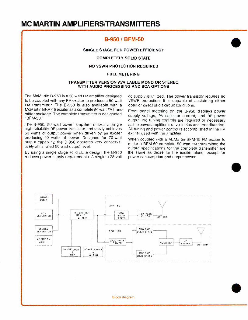
MC MARTIN AMPLIFIERS/TRANSMITTERS
B -950 / BFM -50
SINGLE STAGE FOR POWER EFFICIENCY
COMPLETELY SOLID STATE
NO VSWR PROTECTION REQUIRED
FULL METERING
TRANSMITTER VERSION AVAILABLE MONO OR STEREO WITH AUDIO PROCESSING AND SCA OPTIONS
The McMartin B -950 is a 50 watt FM amplifier designed to be coupled with any FM exciter to produce a 50 watt FM transmitter. The B -950 is also available with a McMartin BFM -15 exciter as a complete 50 watt FM trans- mitter package. The complete transmitter is designated "BFM -50."
The B -950, 50 watt power amplifier, utilizes a single high reliability RF power transistor and easily achieves 50 watts of output power when driven by an exciter producing 10 watts of power. Designed for 70 -watt output capability, the B -950 operates very conserva- tively at its rated 50 watt output level.
By using a single stage solid state design, the B -950 reduces power supply requirements. A single +28 volt
MONO
AUDIO
SCA GENERATOR
STEREO GENERATOR
OPTIONAL MAXI I
RF EXCITER BFM -15
2 -15W
PHASE LOCK a
REF
POWER SUPPLY
a ALARM
BFM- 50
dc supply is utilized. The power transistor requires no VSWR protection. It is capable of sustaining either open or direct short circuit conditions.
Front panel metering on the B -950 displays power supply voltage, PA collector current, and RF power output. No tuning controls are required or necessary as the power amplifier is drive limited and broadbanded. All tuning and power control is accomplished in the FM exciter used with the amplifier.
When coupled with a McMartin BFM -15 FM exciter to make a BFM -50 complete 50 watt FM transmitter, the output specifications for the complete transmitter are the same as those for the exciter alone, except for power consumption and output power.
50W SOLID STATE
I- - - - BEM -100
>-- SOLID STATE
DRIVER
LOW PASS FILTER
V
50W AMP SOLID STATE
40- 60W
50W AMP SOLID STATE
Block diagram
COMBINER LP
FILTER 80 -120W
J
B -9100 / BFM -100
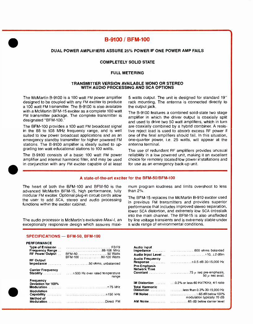
DUAL POWER AMPLIFIERS ASSURE 25% POWER IF ONE POWER AMP FAILS
COMPLETELY SOLID STATE
FULL METERING
TRANSMITTER VERSION AVAILABLE MONO OR STEREO WITH AUDIO PROCESSING AND SCA OPTIONS
The McMartin B -9100 is a 100 watt FM power amplifier designed to be coupled with any FM exciter to produce a 100 watt FM transmitter. The B -9100 is also available with a McMartin BFM -15 exciter as a complete 100 watt FM transmitter package. The complete transmitter is
designated "BFM- 100."
The BFM -100 provides a 100 watt FM broadcast signal in the 88 to 108 MHz frequency range, and is well suited to low power broadcast applications and as an emergency standby transmitter for higher powered FM
stations. The B -9100 amplifier is ideally suited to up- grading ten watt educational stations to 100 watts.
The B -9100 consists of a basic 100 watt FM power amplifier and internal harmonic filter, and may be used in conjunction with any FM exciter capable of at least
5 watts output. The unit is designed for standard 19" rack mounting. The antenna is connected directly to the output jack.
The B -9100 features a combined solid -state two stage amplifier in which the driver output is coaxially split and used to drive two 50 watt amplifiers, which in turn are coaxially combined by a hybrid combiner. A resis- tive reject load is used to absorb excess RF power if
one of the final amplifiers should fail. In this situation, one -quarter power, i.e. 25 watts, will appear at the antenna terminal.
The use of redundant RF amplifiers provides unusual reliability in a low powered unit, making it an excellent choice for remotely located low power installations and for use as an emergency back -up unit.
A state -of- the -art exciter for the BFM- 50 /BFM -100
The heart of both the BFM -100 and BFM -50 is the advanced McMartin BFM -15, high performance, fully modular FM exciter. Optional plug -in circuit cards allow the user to add SCA, stereo and audio processing functions within the exciter cabinet.
The audio processor is McMartin's exclusive Maxi-I, an exceptionally responsive design which assures maxi-
mum program loudness and limits overshoot to less than 2 %.
The BFM -15 replaces the McMartin B -910 exciter used in previous FM transmitters and provides superior performance that includes improved stereo separation, lower SCA distortion, and extremely low SCA crosstalk into the main channel. The BFM -15 is also unaffected by line voltage transients and is extremely stable under a wide range of environmental conditions.
SPECIFICATIONS - BFM -50, BFM -100
PERFORMANCE Type of Emission .. F3 /F9 Audio Input Frequency Range .. 88 -108 MHz Impedance 600 ohms balanced RF Power Output .. BFM -50 50 Watts Audio Input Level .. +10, ±2 dBm
RF Output Impedance
BFM -100 80 -120 Watts
50 ohms, unbalanced
Audio Frequency Response *0.5 dB 30- 15,000 Hz
Pre- Emphasis Carrier Frequency Network Time Stability .... ±500 Hz over rated temperature
range Constant 75 µ sec pre- emphasis,
50 µ sec avail.
Frequency Deviation for 100% IM Distortion ...0.2% or less 60 Hz/7KHz, 4:1 ratio Modulation .75 kHz Total Harmonic Modulation Distortion less than 0.3% 30- 15,000 Hz
Capability Method of
*150 kHz FM Noise >65dB below 100% modulation typically 70 dB
Modulation Direct FM AM Noise 65 dB below carrier level
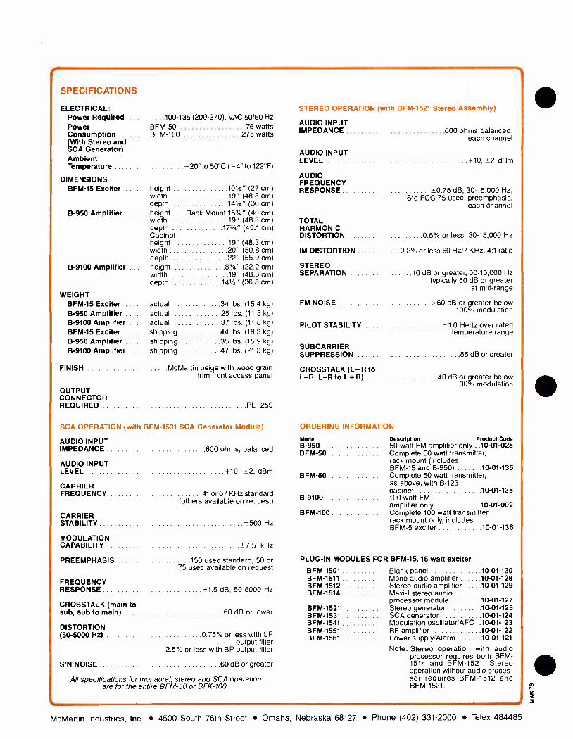
40
SPECIFICATIONS
ELECTRICAL: Power Required .. Power Consumption (With Stereo and SCA Generator) Ambient Temperature
DIMENSIONS BFM -15 Exciter
B -950 Amplifier .. .
B -9100 Amplifier
WEIGHT BFM -15 Exciter ... .
B -950 Amplifier ... .
B -9100 Amplifier .. BFM -15 Exciter ... .
B -950 Amplifier ... B -9100 Amplifier ..
FINISH
OUTPUT CONNECTOR REQUIRED
..100 -135 (200 -270), VAC 50/60 Hz
BFM -50 175 watts BFM -100 275 watts
-20° to 50°C ( -4° to 122°F)
height 101/2" (27 cm) width 19" (48.3 cm) depth 141/4" (36 cm) height ....Rack Mount 153/4" (40 cm) width 19" (48.3 cm) depth 173/4" (45.1 cm) Cabinet height 19" (48.3 cm) width 20" (50.8 cm) depth 22" (55.9 cm) height 83/4" (22.2 cm) width 19" (48.3 cm) depth 141/2" (36.8 cm)
actual 34 lbs. (15.4 kg)
actual 25 lbs. (11.3 kg) actual 37 lbs. (11.8 kg)
shipping 44 lbs. (19.3 kg)
shipping 35 lbs. (15.9 kg)
shipping 47 lbs. (21.3 kg)
McMartin beige with wood grain trim front access panel
PL 259
STEREO OPERATION (with BFM -1521 Stereo Assembly)
AUDIO INPUT IMPEDANCE 600 ohms balanced,
each channel
AUDIO INPUT LEVEL +10, L2, dBm
AUDIO FREQUENCY RESPONSE +0.75 dB, 30- 15,000 Hz,
Std FCC 75 usec, preemphasis, each channel
TOTAL HARMONIC DISTORTION 0 5% or less, 30- 15,000 Hz
IM DISTORTION .0.2% or less 60 Hz/ 7 KHz, 4:1 ratio
STEREO SEPARATION 40 dB or greater, 50- 15,000 Hz
typically 50 dB or greater at mid -range
FM NOISE >60 dB or greater below 100% modulation
PILOT STABILITY . +1.0 Hertz over rated temperature range
SUBCARRIER SUPPRESSION 55 dB or greater
CROSSTALK (L +R to L -R, L -R to L +R) .... 40 dB or greater below
90% modulation
SCA OPERATION (with BFM -1531 SCA Generator Module)
AUDIO INPUT IMPEDANCE
AUDIO INPUT LEVEL
CARRIER FREQUENCY
CARRIER STABILITY
MODULATION CAPABILITY
PREEMPHASIS
FREQUENCY RESPONSE
CROSSTALK (main to sub, sub to main) ... .
DISTORTION (50 -5000 Hz)
S/N NOISE
600 ohms, balanced
+10, +2, dBm
41 or 67 KHz standard (others available on request)
+500 Hz
+7 5 kHz
150 usec standard, 50 or 75 usec available on request
+1.5 dB, 50 -5000 Hz
60 dB or lower
0 75% or less with LP output filter
2.5% or less with BP output filter
60 dB or greater
All specifications for monaural, stereo and SCA operation are for the entire BFM -50 or BFK -100.
ORDERING INFORMATION
Model Description Product Code B -950 50 watt FM amplifier only ..10 -01 -025 BFM -50 Complete 50 watt transmitter,
rack mount (includes BFM -15 and B -950) 10 -01 -135
BFM -50 Complete 50 watt transmitter, as above, with B -123 cabinet 10 -01 -135
B -9100 100 watt FM amplifier only 10 -01 -002
BFM -100 Complete 100 watt transmitter. rack mount only, includes BFM -5 exciter 10 -01 -136
PLUG -IN MODULES FOR BFM -15, 15 watt exciter
BFM -1501 Blank panel 10 -01 -130 BFM -1511 Mono audio amplifier 10 -01 -128 BFM -1512 Stereo audio amplifier 10 -01 -129 BFM -1514 Maxi -1 stereo audio
processor module 10 -01 -127 BFM -1521 Stereo generator 10 -Ui -125 BFM -1531 SCA generator 10 -01 -124 BFM -1541 Modulation oscillator /AFC .10 -01 -123 BFM -1551 RF amplifier 10 -01 -122 BFM -1561 Power supply /Alarm 10 -01 -121
Note: Stereo operation with audio processor requires both BFM - 1514 and BFM -1521. Stereo operation without audio proces- sor requires BFM -1512 and BFM -1521.
McMartin Industries, Inc. 4500 South 76th Street Omaha, Nebraska 68127 Phone (402) 331 -2000 Telex 484485

PORTABLE REMOTE PICKUP TRANSMITTER
RECHARGEABLE BATTERY
DUAL FREQUENCY OPERATION (ONE SUPPLIED)
DESIGN EXCEEDS ALL NEW F.C.C. REQUIREMENTS
150 MHz 3 W PORTABLE REMOTE PICKUP TRANSMITTER
RUGGED LIGHTWEIGHT CONSTRUCTION
ALL SOLID STATE
The McMartin RPU -1103 Portable Remote Pickup Transmitter is a completely self- contained 150 MHz, three watt battery operated transmitter. The transmit- ter is designed to be used by today's on- the -go newsman. When carrying the unit on the shoulder strap, the RPU -1103 allows instant viewing of the controls and indicators. Along with the unique styl- ing, the transmitter provides a degree of audio and RF performance never before available in a portable RPU. The transmitter incorporates the latest in solid state circuit technology. Only the highest quality cir- cuit components, silver mica and tantalum capacitors, are used wherever possible.
Optional two frequency operation is available from the factory or can be added later in the field simply by plugging in the second channel element. Two channel operation with up to 1 MHz separation will not deteriorate performance.
Two high quality audio inputs are provided. The microphone input, located on the front panel, offers 25 dB of compression along with an L.E.D. indicator to display proper operation. A front panel switch is provided to key the transmitter when using the rear mounted line input. This eliminates a live
AUG/80
RPU-1103
microphone condition if the "push -to- talk" button is used to key the transmitter while using the line input. The audio compressor functions on both the line and microphone allowing simple talk over line operation.
A rear compartment provides quick easy access to the battery. A charger jack is located on the rear of the RPU to allow charging of the battery without removal from the transmitter. A fully charged battery is capable of operating the unit on a con- tinuous basis for about one and one half hours, and correspondingly longer on an intermittent basis. If
desired, a field battery change can be quickly ac- complished. Spare batteries are available as an option.
The microphone input jack mates with either a GC -18 -092 or Amphenol 88 -870 or equivalent, one of which is included with each unit. The standard whip antenna provides increased gain and transmitting range over the optional rubber duck type antenna.
The durable aluminum construction complimented by the small size offers an extremely attractive por- table transmitter weighing only six pounds, including battery.
McMartin Industries Inc. 4500 South 76th Street Omaha, Nebraska 68127 (402) 331 -2000 Telex 484485
PRINTED IN U S A

Mc Martin.
CONI XMT CH1
STBY /PTT OFF CH 2
Control panel (top view) of RPU -1103
SPECIFICATIONS
FREQUENCY 150 -172 MHz
CRYSTAL MULTIPLICATION .... Times 12
DUAL FREQUENCY OPERATION Front panel switch selectable
(crystal optional)
SPURIOUS EMISSIONS >60 dB below rated output
RF OUTPUT 3 W nominal POWER REQUIREMENTS
VSWR PROTECTION . No damage incurred by excessive VSWR
RF OUTPUT CONNECTION Type BNC
TEMPERATURE RANGE - 20 ° to 50 °C (0 ° to 120 °F)
MODULATION ... 30F3 adjusted for ± 5 kHz deviation
NOISE >50 dB below 100% modulation
AUDIO INPUTS .... 2 provided, 1 mic input push -to -talk, 1 unbalanced high level input
AUDIO RESPONSE ± 0.75 dB, 50- 7,5000 Hz (75 ps pre- emphasis)
DISTORTION 1 5% 100 -7,500 Hz, 1% typical
AUDIO INPUT LEVEL . ... Microphone - 65 dBm to - 30 dBm Line -20dBmto +18dBm
AUDIO INPUT IMPEDANCE Mic 50/150/600, Line 89./6000
Amphenol 4 pin type 80-871
RCA type Phono Jack
MIC INPUT CONNECTOR
LINE INPUT CONNECTOR
2 5 AH battery, 10-13 V battery internally mounted for quick change.
Battery drain 80 MA standby, 600 MA transmit
DIMENSIONS height width depth
934 '" (24.8 cm) 7"(17.8cm) 3" (7.6 cm)
ORDERING INFORMATION Model Description Product Code
RPU /BAT Replacement 12 V battery 10- 01.115 RPU /BC Battery Charger 10- 01.111 RPU /ANT Antenna, Duck -1 -BNC 10-01-112 RPU/ZCH Second Channel Module 10-01-114 RPU /MIC Microphone 350D, push to
talk 10-01-113
McMartin Industries Inc. 4500 South 76th Street Omaha, Nebraska 68127 (402) 331 -2000 Telex 484485
PRINTED IN U S A
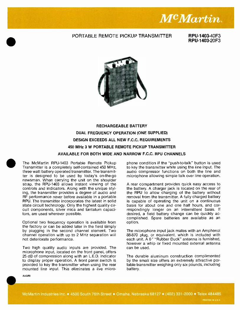
PORTABLE REMOTE PICKUP TRANSMITTER RPU -1403 -40F3 RPU-1403-20F3
RECHARGEABLE BATTERY
DUAL FREQUENCY OPERATION (ONE SUPPLIED)
DESIGN EXCEEDS ALL NEW F.C.C. REQUIREMENTS
450 MHz 3 W PORTABLE REMOTE PICKUP TRANSMITTER
AVAILABLE FOR BOTH WIDE AND NARROW F.C.C. RPU CHANNELS
The McMartin RPU -1403 Portable Remote Pickup Transmitter is a completely self- contained 450 MHz, three watt battery operated transmitter. The transmit- ter is designed to be used by today's on- the -go newsman. When carrying the unit on the shoulder strap, the RPU -1403 allows instant viewing of the controls and indicators. Along with the unique styl- ing, the transmitter provides a degree of audio and RF performance never before available in a portable RPU. The transmitter incorporates the latest in solid state circuit technology. Only the highest quality cir- cuit components, silver mica and tantalum capaci- tors, are used wherever possible.
Optional two frequency operation is available from the factory or can be added later in the field simply by plugging in the second channel element. Two channel operation with up to 2 MHz separation will not deteriorate performance.
Two high quality audio inputs are provided. The microphone input, located on the front panel, offers 25 dB of compression along with an L.E.D. indicator to display proper operation. A front panel switch is provided to key the transmitter when using the rear mounted line input. This eliminates a live micro-
AUG/80
phone condition if the "push -to- talk" button is used to key the transmitter while using the line input. The audio compressor functions on both the line and microphone allowing simple talk over line operation.
A rear compartment provides quick easy access to the battery. A charger jack is located on the rear of the RPU to allow charging of the battery without removal from the transmitter. A fully charged battery is capable of operating the unit on a continuous basis for about one and one half hours, and cor- respondingly longer on an intermittent basis. If desired, a field battery change can be quickly ac- complished. Spare batteries are available as an option.
The microphone input jack mates with an Amphenol 88 -870 plug, or equivalent, which is included with each unit. A 6" "Rubber Duck" antenna is furnished, however a whip or fixed mounted external antenna can be used.
The durable aluminum construction complimented by the small size offers an extremely attractive por- table transmitter weighing only six pounds, including battery.
McMartin Industries Inc. 4500 South 76th Street Omaha, Nebraska 68127 (402) 331 -2000 Telex 484485 PRINTED IN U S A

M'Martin k
Control panel (top view) of RPU -1403
SPECIFICATIONS
FREQUENCY RANGE 450 -456 MHz RPU-1403-40F3 RPU-1403-20F3
Channel Desig. N1, R (50 KHz) N2 (25 KHz) OSCILLATOR
Audio Response 30-10 KHz -±1 dB 30-5 KHz 1 dB MULTIPLICATION Times 36 Carrier Dev. +10 KHz ±5 KHz
FREQUENCY STABILITY 0005% PRE -EMPHASIS 75 microsecond, standard
DUAL FREQUENCY LED OPERATION Front Panel Switch Selectable, INDICATORS Rectified RF output
max. separation 2 MHz. 3 dB audio 'Peak Flasher' (Second crystal optional) Battery Condition
SPURIOUS POWER REQUIRED 2 5 AH battery, 10 -13 volt battery EMISSIONS
RF OUTPUT
VSWR
>60 dB below rated output
3W nominal
DIMENSIONS
internally mounted for quick change. Battery drain 80 MA standby,
800 MA transmit
93/4" (24.77 cm) height PROTECTION No damage incurred by
excessive VSWR 7" (17.78 cm) width 3" (7.62 cm) depth
RF OUTPUT FINISH McMartin beige and bronze with CONNECTION Type BNC simulated leather exterior.
Rugged shoulder strap. TEMPERATURE RANGE -30 to +50° C
-20 to +120° F WEIGHT 7.7 lbs. (3.5 kg)
AUDIO INPUT IMPEDANCE Mic 50/150/600 Balanced
Line 8 ohm /600 Unbal.
MIC INPUT CONNECTOR Amphenol 4 pin type 80 -871 ORDERING INFORMATION
(Push -to -Talk) MODEL DESCRIPTION PRODUCT CODE RPU -1403 Portable Remote Pick -up 10 -01 -087
LINE INPUT Transmitter CONNECTOR RCA type Phono Jack
RPU /BAT Battery 12 volts, replacement ..10 -01 -115
AUDIO INPUT LEVEL Microphone -65 dBm to -30 dBm
RPU /BC Battery Charger 10 -01 -111
Line -20 dBm to +18 dBm RPU /ANT 450 MHz ... Antenna (rubber duck), 10 -01 -118 replacement
FM NOISE 50 dB below 100% modulation -55 dB typical RPU /2CH Second Channel Module 10 -01 -114
DISTORTION Less than 1.5% within audio bandpass; 0.75% typical
RPU /MIC Microphone 350D, 10 -01 -113 push to talk
cMartin Industries Inc. 4500 South 76th Stree maha, Nebraska 6812 ; 402) 331 -2000 Telex 484485 PRINTED IN U S
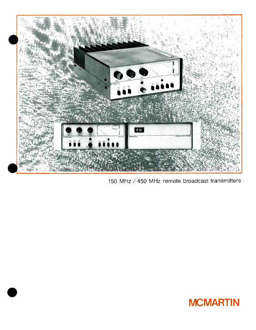
150 MHz / 450 MHz remote broadcast transmitters
MU MARTIN
150 -170 MHz and 450 -455 MHz broadcast quality remote pick -up transmitters. Mobile of Fixed Base Operation.
Front panel multimeter indicates modulation, forward, and reflected power, Vc, IPA
Dual frequency operation Microphone and line transformer inputs.
Compressor limiter operates on both line and mic inputs.
Talk over line input capability. Latest design exceeds all new F.C.C. requirements.
Rugged lightweight construction (weighs only 8 lbs.).
All solid state; High VSWR and Thermal Overload protected.
Use of highest quality components. Full -line of accessories available including 120/240 VAC power supply, rack mount
frame, antennas, etc.
Superior serviceability.
The McMartin RPU -1150 and RPU -1430 Remote Broadcast transmitters incorporate the latest in FM solid state technology and are designed for high audio quality remote broadcast program origination. The RPU -1150 operates on a specified frequency in the range of 150 -170 MHz with a continuous power output rating of 50 watts.
The RPU -1430 operates on a specified frequency in the 450 -455 MHz range with a continuous power output of 30 watts. The units are identical in size and appearance and utilize the same accessories except for antennas.
The basic unit is designed for 13.5 VDC mobile power sources but can also be operated from 115 or 230 VAC, 50 -60 Hz with an optional companion power supply. The supply can be mounted separately or side -by -side with the transmitter in an optional rack -mount cabinet. By removing the de- mountable rack ears and attaching a carrying handle (supplied), the cabinet doubles as a smart portable carrying case.
The unit is equipped with a full complement of front panel - mounted controls and has provisions for a remote control head. A combination under -dash /floor mount cradle is fur- nished as standard for mobile operation.
A switch -selected multimeter allows the user to read forward and reflected RF power, modulation level, supply voltage and power amplifier current.
The RPU -1150 and RPU -1430 employ a direct FM modula- tion process employing a crystal oscillator operating at 1/12 or
1/36 the output frequency. The transmitter has built -in two channel capability. All that is required to expand the operation to two channels is install the second plug -in channel element. The frequency is then determined by the front panel or remote channel select switch. Both frequencies must be in the same FCC channel grouping.
The audio processing circuitry provides excellent limiting characteristics with minimum distortion. Excellent overload and dynamics range characteristics are ensured by the use of two section microphone gain controls. This permits the use of either high performance or close talking microphones with nominal output levels over the range of -60 to -30 dBm.
The RF power amplifier is a completely solid state design, conservatively rated for continuous RF output. It is capable of withstanding infinite VSWR conditions at rated supply voltage and drive levels and is thermostatically protected against long- term mismatch or overload conditions.
All interstage and output impedance matching is accom- plished with broadband microstrip techniques and there are no amplifier tuning adjustments to be made.
A convenient built -in VSWR bridge enables the user to check or adjust the antenna system for a favorable match to effect maximum radiated power.
The transmitters utilize harmonic and spurious suppression techniques that attenuate all undesired signals well below present FCC and international standards.
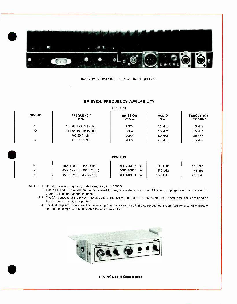
Rear View of RPU 1150 with Power Supply (RPU /PS)
EMISSION /FREQUENCY AVAILABILITY
RPU-1150
GROUP FREQUENCY EMISSION AUDIO FREQUENCY MHz DESIG. B.W. DEVIATION
K1 152.87-153.35 (9 ch.) 25F3 7.5 kHz 5 kHz
K2 161.64-161.76 (5 ch.) 25 F3 7.5 kHz ±5 kHz
L 166.25 (1 ch.) 20F3 5.0 kHz ±5 kHz
M 170.15 (1 ch.) 20F3 5.0 kHz -5 kHz
RPU-1430
N1 450 (6 ch.) 455 (6 ch.) 40F3/40F3A * 10.0 kHz 10 kHz N2 450 (12 ch.) 455 (12 ch.) 20F3/20F3A * 5.0 kHz ±5 kHz R 450 (5 ch.) 455 (6 ch.) 40F3/40F3A * 10.0 kHz ±10 kHz
NOTE: 1. Standard carrier frequency stability required is x.0005 %. 2. Group Ni and R channels may only be used for program material and cues. All other groupings listed can be used for
program, cues and communications. * 3. The (A) versions of the RPU -1430 designate frequency tolerance of .- .0002% required when these units are used as
base stations or mobile repeators. 4. For dual frequency operation. both operating frequencies must be in the same channel group. Additionally. the maximum
channel spacing at 455 MHz should be less than 2 MHz.
MCMaretn.
G vtr
LINE
RPU
RPU /MC Mobile Control Head

SPECIFICATIONS
OPERATING FREQUENCY RANGE
RF OUTPUT POWER
POWER REQUIRED
RPU -1150 RPU -1430
148 -172 MHz 450 -456 MHz
50 watts 30 watts (Minimum continuous @ 13.5 VDC into 50 ohms.)
10A 7A transmit transmit
100 MA 100 MA Standby Standby
RF OUTPUT CONNECTION
DIMENSIONS
WEIGHT
FINISH
Type SO -239
height 31/2" (9 cm) width 81/2" (20 cm) depth 13" (33 cm)
actual 7.7 lbs. (3.5 kg) shipping 11 lbs. (5 kg)
McMartin Beige & Bronze, on heavy -duty aluminum cabinet
OSCILLATOR MULTIPLICATION
TEMPERATURE RANGE
SPURIOUS EMISSIONS
MODULATION
FREQUENCY STABILITY
FM and AM NOISE
FREQUENCY RESPONSE'
see NOTE
AUDIO DISTORTION
MODULATION CONTROL
AUDIO LIMITING
AUDIO INPUTS
AUDIO INPUT LEVEL
AUDIO INPUT IMPEDANCE
MIC INPUT CONNECTORS
LINE INPUT CONNECTION
@ 13.5 VDC. (12.5 to 14.5 VDC operating range)
X12 X36
-20 to 120° F. ( -30 to 50` C)
..Greater than 65 dB below rated output
Direct FM VCXO; See table for licensed frequencies and bandwidths.
.0005 °ro STD .0002% for 450 MHz fixed stations.
Better than -50 dB below 100% modulation -55 dB typical
30 Hz to 5 kHz, 7.5 kHz, or 10 kHz -±1 dB depending on licensed channel BW. 75 microsecond
pre- emphasis is standard on all units.
0.8% typical 1.5% maximum, 50 -7500 Hz
By means of audio filter and compressor -limiter
25 dB at 2 millisecond attack time. 300 millisecond delay
3 independent, 2 mit input push -to -talk, 1 high level line input
Microphone -65 dBm to -30 dBm. Line -20 dBm to +18 dBm
Mic 50/150/600 balanced, Line 8 to 600 ohm balanced
or unbalanced.
Amphenol 4 pin type XLR -31
Phone Jack, unbalanced; term strip, balanced
NOTE: Unless otherwise specified, unit will be supplied with audio filter and carrier deviation adjusted as follows:
CHANNEL AUDIO CARRIER EMISSION GROUP BANDWIDTH DEVIATION DESIG.
K1, K2 7.5 kHz ±5 kHz 25F3 L. M 5.0 kHz ±5 kHz 20F3 N2 5.0 kHz ±5 kHz 20F3 N1, R 10.0 kHz ±10 kHz 40F3
75 microseconds Pre -emphasis is standard in all units.
ORDERING INFORMATION
MODEL DESCRIPTION PRODUCT CODE
RPU -1150 50 watt 150 MHz remote pickup transmitter. Includes mobile mount, requires 13.5 volt DC @ 10 amps transmit. (Specify frequency) 10 -01 -088
RPU -1430 30 watt 450 MHz remote pickup transmitter. Includes mobile mount, requires 13.5 volt DC @ 7 amps transmit. (Specify frequency) 10 -01 -089
RPU /PS AC power supply 10 -01 -095
RPU /RmCc Rack mount and carrying case provides convenient carrying case and rack mount- ing for both the power supply and 50 or 30 watt transmitter (Not required for mobile installations) 10 -01 -096
RPU /MC Mobile control head for use when unit is trunk mounted. Includes cable from control head to transmitter. 10 -01 -098
McMartin Industries Inc. 4500 South 76th Street Omaha, Nebraska 68127 Phone (402) 331 -2000 Telex 484485
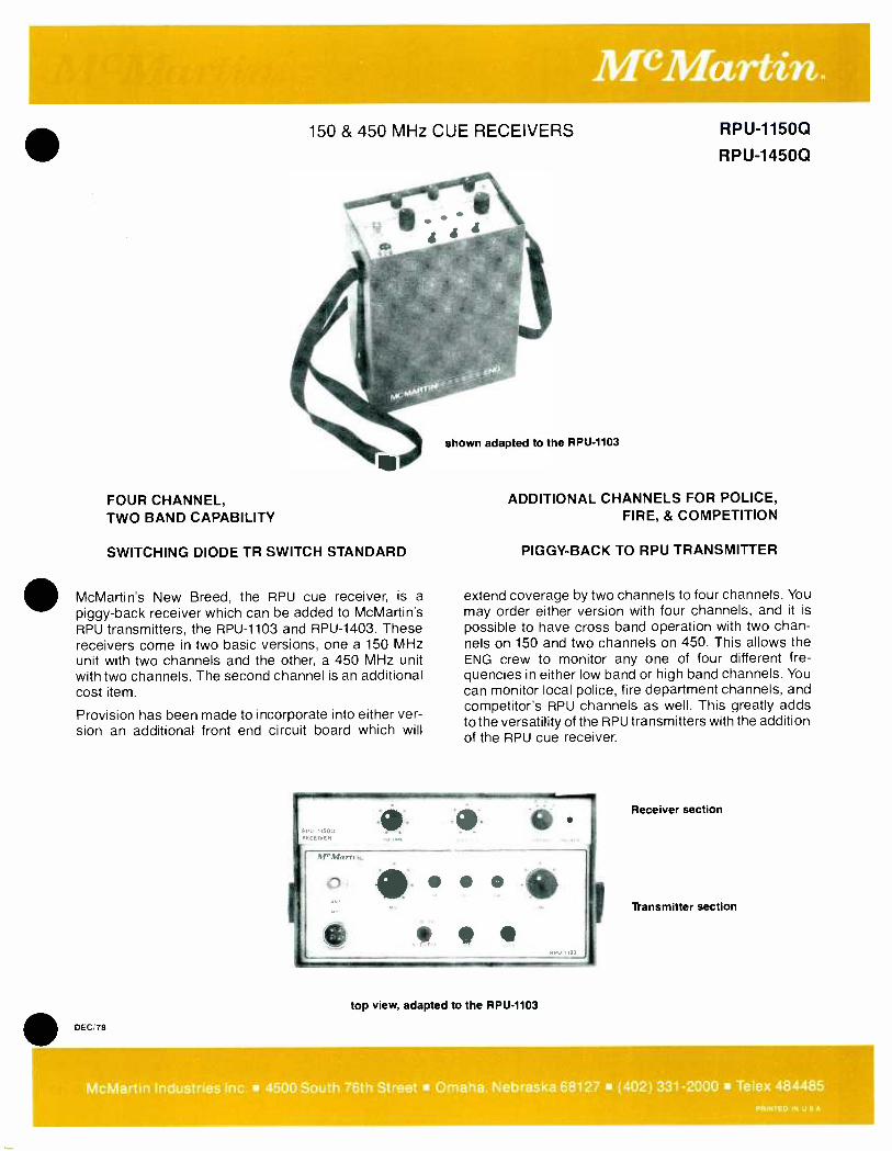
150 & 450 MHz CUE RECEIVERS
FOUR CHANNEL, TWO BAND CAPABILITY
SWITCHING DIODE TR SWITCH STANDARD
McMartin's New Breed, the RPU cue receiver, is a piggy -back receiver which can be added to McMartin's RPU transmitters, the RPU -1103 and RPU -1403. These receivers come in two basic versions, one a 150 MHz unit with two channels and the other, a 450 MHz unit with two channels. The second channel is an additional cost item.
Provision has been made to incorporate into either ver- sion an additional front end circuit board which will
DEC/78
shown adapted to the RPU -1103
RPU-1150Q
R PU-1450Q
ADDITIONAL CHANNELS FOR POLICE, FIRE, & COMPETITION
PIGGY -BACK TO RPU TRANSMITTER
extend coverage by two channels to four channels. You may order either version with four channels, and it is
possible to have cross band operation with two chan- nels on 150 and two channels on 450. This allows the ENG crew to monitor any one of four different fre- quencies in either low band or high band channels. You can monitor local police, fire department channels, and competitor's RPU channels as well. This greatly adds to the versatility of the RPU transmitters with the addition of the RPU cue receiver.
top view, adapted to the RPU -1103
Receiver section
Wansmitter section
McMartin Industries Inc. 4500 South 76th Street Omaha. Nebraska 68127 (402) 331 -2000 Telex 484485 PRINTED IN U S A
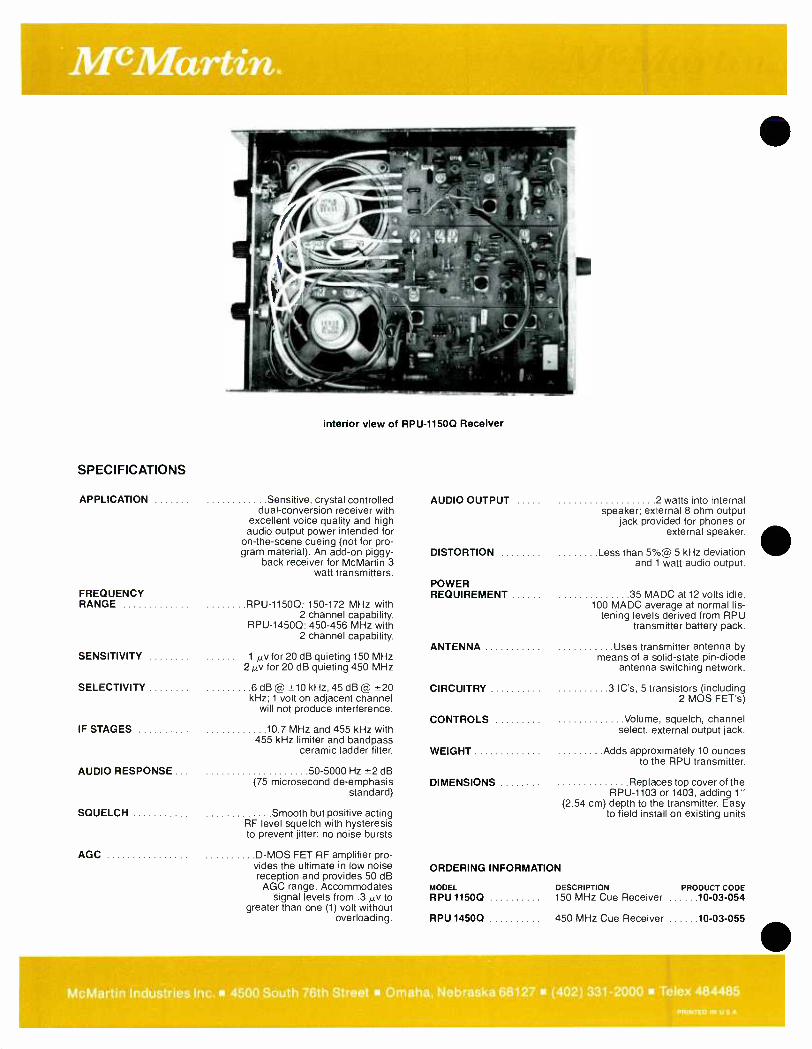
interior view of RPU -11500 Receiver
SPECIFICATIONS
APPLICATION Sensitive, crystal controlled dual- conversion receiver with
excellent voice quality and high audio output power intended for
on- the -scene cueing (not for pro- gram material). An add -on piggy-
back receiver for McMartin 3 watt transmitters.
FREQUENCY RANGE RPU -11500: 150 -172 MHz with
2 channel capability. RPU -14500: 450 -456 MHz with
2 channel capability.
SENSITIVITY 1µv for 20 dB quieting 150 MHz 2µv for 20 dB quieting 450 MHz
SELECTIVITY 6 dB @ ±10 kHz, 45 dB @ ±20 kHz; 1 volt on adjacent channel
will not produce interference.
IF STAGES 10.7 MHz and 455 kHz with 455 kHz limiter and bandpass
ceramic ladder filter.
AUDIO RESPONSE ... 50 -5000 Hz ±2 dB (75 microsecond de- emphasis
standard)
SQUELCH Smooth but positive acting RF level squelch with hysteresis to prevent jitter; no noise bursts
AGC D -MOS FET RF amplifier pro- vides the ultimate in low noise reception and provides 50 dB
AGC range. Accommodates signal levels from .3 µv to
greater than one (1) volt without overloading.
AUDIO OUTPUT 2 watts into internal speaker; external 8 ohm output
jack provided for phones or external speaker.
DISTORTION Less than 5 %@ 5 kHz deviation and 1 watt audio output.
POWER REQUIREMENT 35 MADC at 12 volts idle,
100 MADC average at normal lis- tening levels derived from RPU
transmitter battery pack.
ANTENNA Uses transmitter antenna by means of a solid -state pin -diode
antenna switching network.
CIRCUITRY 3 IC's, 5 transistors (including 2 MOS FET's)
CONTROLS Volume, squelch, channel select, external output jack.
WEIGHT Adds approximately 10 ounces to the RPU transmitter.
DIMENSIONS Replaces top cover of the RPU -1103 or 1403, adding 1"
(2.54 cm) depth to the transmitter. Easy to field instaI on existing units
ORDERING INFORMATION
MODEL DESCRIPTION PRODUCT CODE RPU 1150Q 150 MHz Cue Receiver 10 -03 -054
RPU 1450Q 450 MHz Cue Receiver 10 -03 -055
McMartin Industries Inc. 4500 South 76th Street Omaha, Nebraska 68127 (402) 331 -2000 Telex PRINTED IN U S.
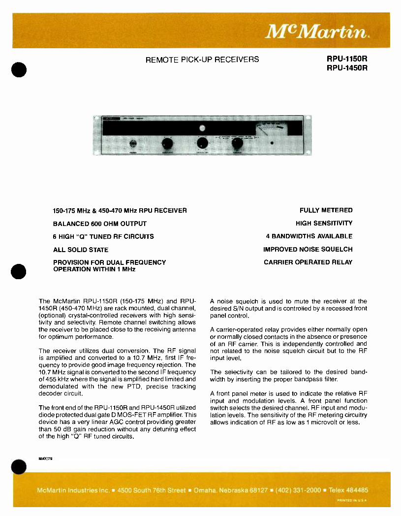
McMartin. REMOTE PICK -UP RECEIVERS
.21011 was tin.
150 -175 MHz & 450 -470 MHz RPU RECEIVER
BALANCED 600 OHM OUTPUT
6 HIGH "Q" TUNED RF CIRCUITS
ALL SOLID STATE
PROVISION FOR DUAL FREQUENCY OPERATION WITHIN 1 MHz
The McMartin RPU -1150R (150 -175 MHz) and RPU - 1450R (450 -470 MHz) are rack mounted, dual channel, (optional) crystal -controlled receivers with high sensi- tivity and selectivity. Remote channel switching allows the receiver to be placed close to the receiving antenna for optimum performance.
The receiver utilizes dual conversion. The RF signal is amplified and converted to a 10.7 MHz, first IF fre- quency to provide good image frequency rejection. The 10.7 MHz signal is converted to the second IF frequency of 455 kHz where the signal is amplified hard limited and demodulated with the new PTD, precise tracking decoder circuit.
The front end of the RPU -1150R and RPU -1450R utilized diode protected dual gate D MOS -FET RF amplifier. This device has a very linear AGC control providing greater than 50 dB gain reduction without any detuning effect of the high "Q" RF tuned circuits.
MAY/79
RPU-1150R RPU-1450R
FULLY METERED
HIGH SENSITIVITY
4 BANDWIDTHS AVAILABLE
IMPROVED NOISE SQUELCH
CARRIER OPERATED RELAY
A noise squelch is used to mute the receiver at the desired S/N output and is controlled by a recessed front panel control.
A carrier -operated relay provides either normally open or normally closed contacts in the absence or presence of an RF carrier. This is independently controlled and not related to the noise squelch circuit but to the RF input level.
The selectivity can be tailored to the desired band- width by inserting the proper bandpass filter.
A front panel meter is used to indicate the relative RF input and modulation levels. A front panel function switch selects the desired channel. RF input and modu- lation levels. The sensitivity of the RF metering circuitry allows indication of RF as low as 1 microvolt or less.
McMartin Industries Inc. 4500 South 76th Street Omaha. Nebraska 68127 (402) 331 -2000 Telex 484485 PRINTED IN U S A

W.:.
SPECIFICATIONS CARRIER FREQUENCY RANGE
DUAL FREQUENCY OPERATION
INPUT IMPEDANCE ..
SENSITIVITY
SELECTIVITY
RPU-1150R
150 -175 MHz
Two frequency operation with 1
MHz spacing. Second channel
operation optional.
50 ohm BNC connector
0.5 microvolts for 20 dB quieting referenced from ±5 kHz deviation
@ 400 Hz
±15 kHz @6 dB ±40 kHz @ 60 dB.
Determined by deviation specified
Rear view of RPU -1450R
RPU-1450R
450 -470 MHz
Two frequency operation with 2 MHz spacing.
Second channel operation optional.
50 ohm BNC connector
0.5 microvolts for 20 dB quieting referenced from ±5 kHz deviation
@ 400 Hz
±15 kHz @6 dB ±60 kHz @ 60 dB.
Optional filters available.
Determined by deviation specified
RF FILTERING Double shielding of RF and oscillator circuits
METERING 2 Channels - RF input level and modulation
POWER REQUIREMENTS
DIMENSIONS
WEIGHT
FINISH
120 VAC 50/60 Hz, 25 watts
Standard rack mount: Width - 19" (48.3 cm) Height - 31/2" (8.9 cm) Depth -11 " (27.9 cm)
actual 10 lbs. (4.5 kg) shipping 13 lbs. (5.9 kg)
ORDERING INFORMATION
McMartin beige with woodgrain trim
S/N RATIO 55 dB below 100 %, 60 dB typical Model Description Product Code
SPURIOUS RPU -1150R Receiver, 150 MHz,
rack mount, 2 channel 10 -03 -032
RESPONSE At least 65 dB (specify frequency)
AUDIO OUTPUT Balanced 600 ohm +10 dBm RPU -1450R Receiver, 450 MHz rack mount, 2 channel
10 -03 -033
SQUELCH Adjustable up to 20 µ volts (specify frequencies)
McMartin Industries Inc. 4500 South 76th Street Omaha, Nebraska 68127 (402) 331 -2000 Telex 484485 PRIVTED IN USA
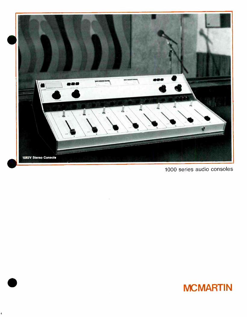
1000 series audio consoles
MCMARTI N

5 Channel Stereo / vertical attenuators
8 Channel Stereo or Mono / vertical attenuators
8 Channel Stereo or Mono / rotary attenuators
Gold plated PCB contacts
All channels convertible to MIC or HI level inputs
15 watts Monitor amplifier output Headphone amplifier with volume control
Cue amplifier
External power supply
10 inputs into 5 mixer (5 channel consoles)
18 inputs into 8 mixer (8 channel consoles)
Audition output usable as 2nd program output Cassette Input Jack 8- Channel Models
The McMartin B -1000 Series of audio consoles is a new breed of human -engineered, easy -to -live- with consoles that last and last. Clean design keeps board operations tight and accurate. Clean construction and internal lay -out makes service, when required, fast and easy. Clean engineering assures you of a clean signal.
FIVE OR EIGHT CHANNELS
Plenty of inputs are provided for a variety of broadcast production needs. The eight channel models have 18 inputs while the five channel models provide for 10. This affords sufficient input selec- tion for most of today's broadcast requirements.
VERTICAL OR ROTARY ATTENUATORS
Both mono and stereo versions come with either vertical, recording studio type slide attenuators or the more commonly used rotary attenuators. Either style provides the operator with the precision control necessary to meet the demands of today's broadcasting.
ALL CHANNELS CONVERTIBLE All channel positions can be converted to mic. or line inputs, the line inputs either balanced or unbalanced. Check the ordering information for the standard configuration of mic. and line inputs.
Cue and talkback controls Pushbutton input select switches
STEREO OR MONO
The design of the B -1000 Series was conceived with stereo perfor- mance in mind. Mechanically both stereo and mono units are the same. Many of the functional parts in the monaural units are the same as those used in the stereo versions. This similarity of parts provides greater value per dollar than is found in some units costing consid- erably more. Monaural stations contemplating conversion to stereo at a later date will find the 1000 series stereo console an excellent investment in future growth.
HEADPHONE AMPLIFIER WITH VOLUME CONTROL
Headphone amplifier can be switched to monitor several console functions. Check the picture for the versatility provided.
FIFTEEN WATT MONITOR OUTPUT AMPLIFIER Enough power for almost any monitor speaker is provided without requiring the use of an external monitor amplifier. The hybrid ampli- fier modules easily provide up to 15 watts per channel output.
CUP 1 7
Slide attenuators,
8
Monitor and rotaries also available headphone select controls
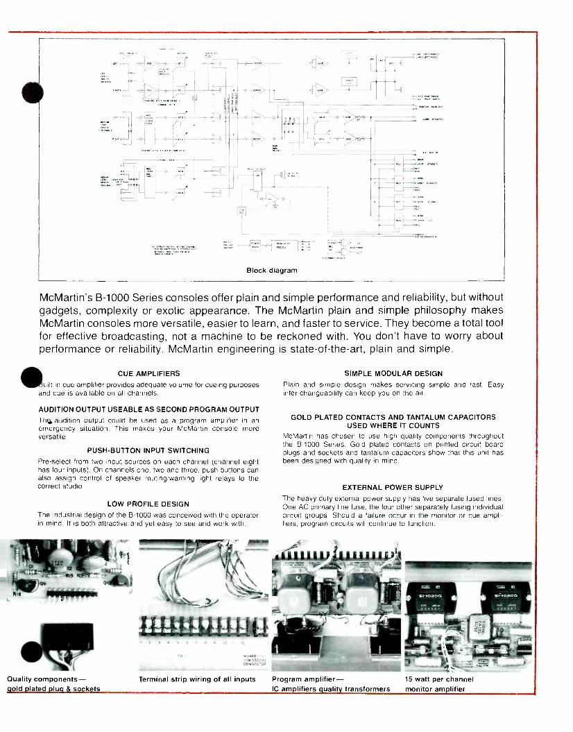
-
...,o-nMxr<tl .,> -
f>
Block diagram
" McMartin's B -1000 Series consoles offer plain and simple performance and reliability, but without gadgets, complexity or exotic appearance. The McMartin plain and simple philosophy makes McMartin consoles more versatile, easier to learn, and faster to service. They become a total tool for effective broadcasting, not a machine to be reckoned with. You don't have to worry about performance or reliability. McMartin engineering is state -of- the -art, plain and simple.
CUE AMPLIFIERS
wilt in cue amplifier provides adequate volume for cueing purposes and cue is available on all channels.
AUDITION OUTPUT USEABLE AS SECOND PROGRAM OUTPUT
The, audition output could be used as a program amplifier in an emergency situation. This makes your McMartin console more versatile.
PUSH- BUTTON INPUT SWITCHING
Pre -select from two input sources on each channel (channel eight has four inputs). On channels one, two and three, push- buttons can also assign control of speaker muting /warning light relays to the correct studio.
LOW PROFILE DESIGN
The industrial design of the B -1000 was conceived with the operator in mind. It is both attractive and yet easy to see and work with.
SIMPLE MODULAR DESIGN
Plain and simple design makes servicing simple and fast. Easy inter -changeability can keep you on the air.
GOLD PLATED CONTACTS AND TANTALUM CAPACITORS USED WHERE IT COUNTS
McMartin has chosen to use high quality components throughout the B -1000 Series. Gold plated contacts on printed circuit board plugs and sockets and tantalum capacitors show that this unit has been designed with quality in mind.
EXTERNAL POWER SUPPLY
The heavy duty external power supply has five separate fused lines. One AC primary line fuse. the four other separately fusing individual circuit groups. Should a failure occur in the monitor or cue ampli- fiers, program circuits will continue to function.
Quality components- old Iated lu & sockets
Terminal strip wiring of all inputs Program amplifier- 15 watt per channel IC amlifiers ualit transformers monitor am Wier
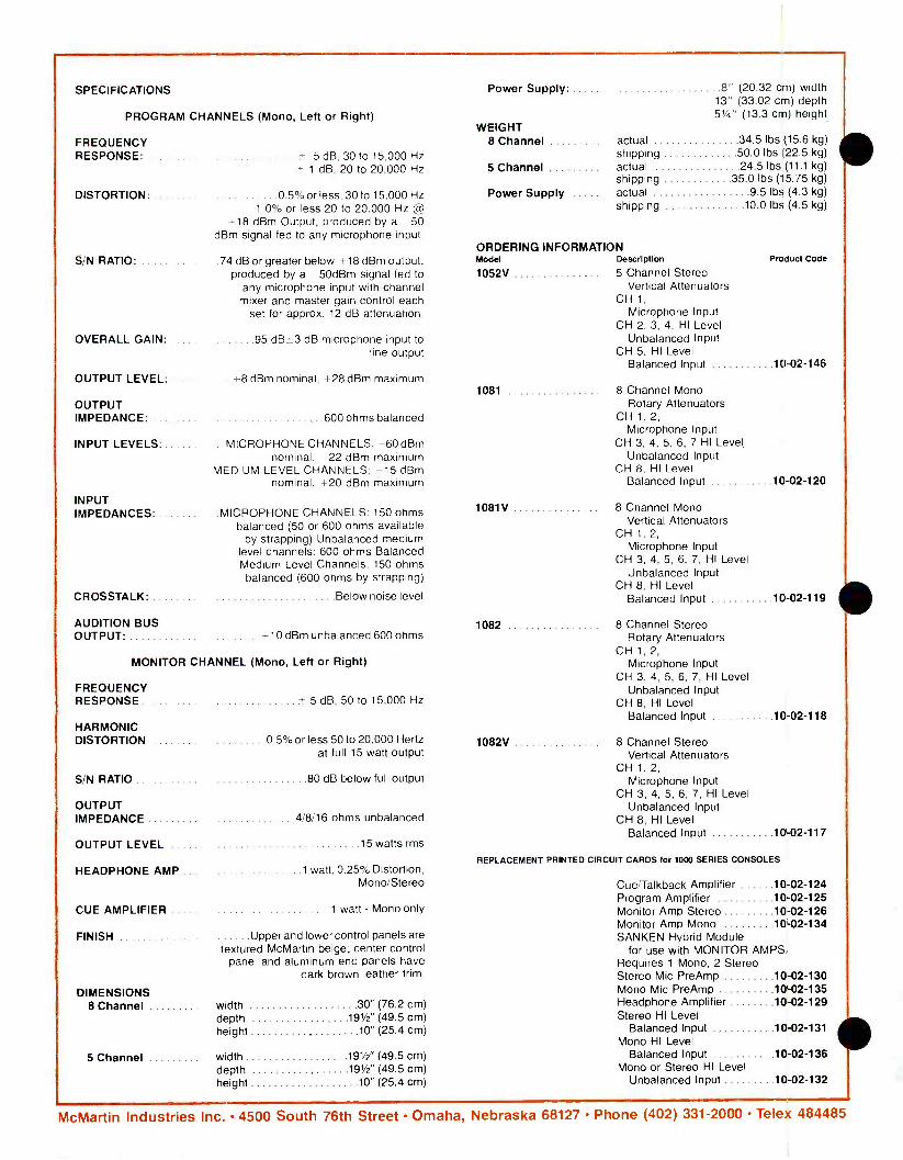
SPECIFICATIONS
PROGRAM CHANNELS (Mono, Left or Right)
FREQUENCY RESPONSE: 5 dB, 30 to 15,000 Hz
± 1 dB, 20 to 20,000 Hz
DISTORTION 0.5% or less, 30 to 15,000 Hz 1.0% or less 20 to 20,000 Hz @
+18 dBm Output, produced by a -50 dBm signal fed to any microphone input.
S/N RATIO: .74 dB or greater below +18 dBm output, produced by a -50dBm signal fed to
any microphone input with channel mixer and master gain control each
set for approx. 12 dB attenuation.
OVERALL GAIN: 95 dB-+-3 dB microphone input to line output
OUTPUT LEVEL- ... { 8 dBm nominal, +28 dBm maximum
OUTPUT IMPEDANCE: 600 ohms balanced
INPUT LEVELS .MICROPHONE CHANNELS; -60dBm nominal, 22 dBm maximum
MEDIUM LEVEL CHANNELS; -15 dBm nominal. + 20 dBm maximum
INPUT IMPEDANCES .MICROPHONE CHANNELS: 150 ohms
balanced (50 or 600 ohms available by strapping) Unbalanced medium
level channels: 600 ohms Balanced Medium Level Channels: 150 ohms balanced (600 ohms by strapping)
CROSSTALK: Below noise level
AUDITION BUS OUTPUT: +10 dBm unbalanced 600 ohms
MONITOR CHANNEL (Mono, Left or Right)
FREQUENCY RESPONSE +.5 dB, 50 to 15,000 Hz
HARMONIC DISTORTION 0.5 % or less 50 to 20,000 Hertz
at full 15 watt output
S/N RATIO 80 dB below full output
OUTPUT IMPEDANCE 4/8/16 ohms unbalanced
OUTPUT LEVEL 15 watts rms
HEADPHONE AMP ... 1 watt, 0.25% Distortion, Mono /Stereo
CUE AMPLIFIER 1 watt - Mono only
FINISH Upper and lower control panels are textured McMartin beige; center control
panel and aluminum end panels have dark brown leather trim.
DIMENSIONS 8 Channel
5 Channel
width 30" (76.2 cm) depth 191/2" (49.5 cm) height 10" (25.4 cm)
width 191/2" (49.5 cm) depth 191/2" (49.5 cm) height 10" (25.4 cm)
Power Supply 8" (20.32 cm) width 13" (33.02 cm) depth 51/4" (13.3 cm) height
WEIGHT 8 Channel actual 34.5 lbs (15.6 kg)
shipping 50.0 lbs (22.5 kg)
5 Channel actual 24.5 lbs (11.1 kg) shipping 35.0 lbs (15.75 kg)
Power Supply actual 9.5 lbs (4.3 kg) shipping 10.0 lbs (4.5 kg)
ORDERING INFORMATION Model Description Product Code
1052V 5 Channel Stereo Vertical Attenuators
CH 1,
Microphone Input CH 2, 3, 4, HI Level
Unbalanced Input CH 5, HI Level
Balanced Input 10 -02 -146
1081 8 Channel Mono Rotary Attenuators
CH 1, 2, Microphone Input
CH 3, 4, 5, 6, 7 HI Level Unbalanced Input
CH 8, HI Level Balanced Input 10 -02 -120
1081V 8 Channel Mono Vertical Attenuators
CH 1, 2, Microphone Input
CH 3, 4, 5, 6, 7, HI Level Unbalanced Input
CH 8, HI Level Balanced Input 10 -02 -119
1082 8 Channel Stereo Rotary Attenuators
CH 1, 2, Microphone Input
CH 3, 4, 5, 6, 7, HI Level Unbalanced Input
CH 8, HI Level Balanced Input 10 -02 -118
1082V 8 Channel Stereo Vertical Attenuators
CH 1, 2, Microphone Input
CH 3, 4, 5, 6, 7, HI Level Unbalanced Input
CH 8, HI Level Balanced Input 10 -02 -117
REPLACEMENT PRINTED CIRCUIT CARDS for 1000 SERIES CONSOLES
Cue /Talkback Amplifier 10 -02 -124 Program Amplifier 10 -02 -125 Monitor Amp Stereo 10 -02 -126 Monitor Amp Mono 10 -02 -134 SANKEN Hybrid Module
for use with MONITOR AMPS. Requires 1 Mono, 2 Stereo Stereo Mic PreAmp 10 -02 -130 Mono Mic PreAmp 10 -02 -135 Headphone Amplifier 10 -02 -129 Stereo HI Level
Balanced Input 10 -02 -131 Mono HI Level
Balanced Input 10 -02 -136 Mono or Stereo HI Level
Unbalanced Input 10 -02 -132
McMartin Industries Inc. 4500 South 76th Street - Omaha, Nebraska 68127 Phone (402) 331 -2000 Telex 484485
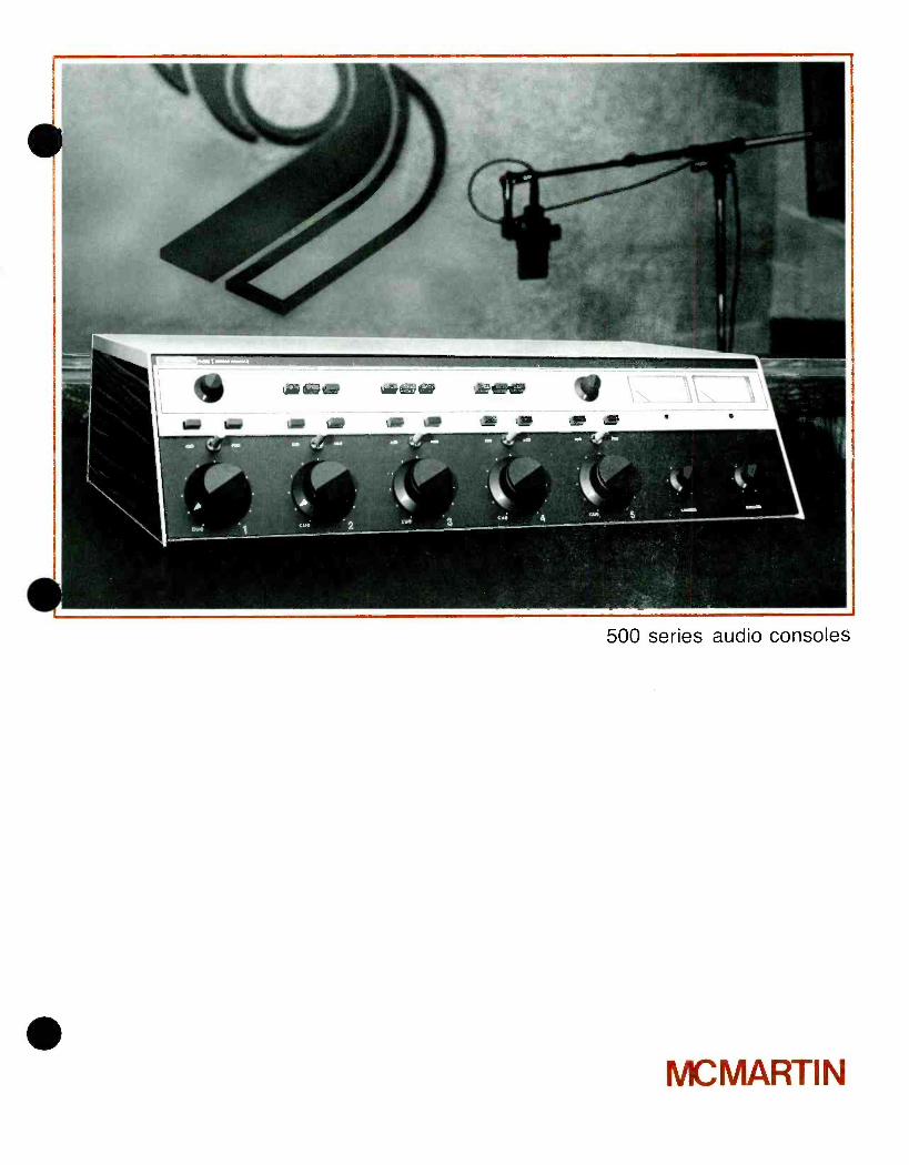
500 series audio consoles
MCMARTIN
Compact Design Ideal for Production and Small On -Air Studios As Well As Mobile Units
Excellent Performance Specifications
Plug -in Modular Design
Input Modules Available for: Microphone and Balanced High -Level
Standard Configuration One Microphone, Four Balanced High Level Inputs
Other Input Combinations by Simple Plug -in Module Substitution Two Preselect Inputs Per Mixer
Four Watt rms Monitor Amplifier
Cue on All Mixers
Built -in Cue -Amplifier and Speaker
Speaker Muting for One Studio, Muting for Second Studio Optional
Functional, Large, Well Located Controls Monaural, and Stereo Models
The McMartin B -500 series five -mixer audio consoles have been designed to provide for audio mixing and control for production and broadcasting application. Two models in the B -500 series are available, the B -501 monaural console and the B -502 stereo console.
B -500 series consoles provide five mixing channels, with switch selection of two inputs per mixer (a total of 10 inputs are provided). Each mixer output may be switched to the program or the audition busses of the console. Each mixer is provided with a detented counter -clockwise cue switch, to allow aural monitoring of any input channel by means of an integral 2 -watt cue amplifier and built -in cue speaker. A front panel cue gain control is provided.
The five mixers are precision molded composition triple wiper attenuators which will typically operate for over 5 million operations without mechanical or electrical degradation. B -500 series five mixer consoles are available with step attenuators. These are identified by the basic model number plus the suffix "SA" for the step attenuator models.
Plug -in modules are used in the program and audition channels of the B -500 consoles. Input cards are available for microphone and for balanced high level inputs.
The use of these plug -in cards permits the user to tailor the console to his specific operating requirement. The standard models are supplied with one microphone preamplifier and four balanced high level input modules. Numerous other combinations are available as original purchase options or may be changed in the field at any time simply by unplugging one card, and plugging in the desired type input card.
The microphone preamplifiers accept low impedance balanced microphones of 150 ohm or 250 ohm impedance.
Balanced high level input cards are factory wired to accept 600 ohm balanced line inputs. Additional transformer taps accommodate 150 ohm or 50 ohm balanced inputs.
Each console is provided with a speaker muting /warning light relay for one location that operates in conjunction with the A input of mixer #1. Switching of that input to either the audition or the program bus will activate the relay. A prewired socket accepts an optional second relay for an additional location. It is connected to operate in conjunction with the B input of mixer #1. Spare contacts are available on all channel lever key switches, and on input select pushbuttons to allow extension of the muting /warning light relay control wiring to any or all other mixing channels.
All wiring connections to B -500 consoles are by means of rear panel mounted barrier type screw terminal strips. Space and cutouts are provided to allow field installation of two XLR -3 microphone connectors.
Convenient headphone jacks for monitoring are provided on both models, with front panel switch selection of the program, audition or cue busses.
The console outputs may be switched to two output lines or to an internal terminating load.
Program outputs are for 600 ohm balanced lines, and are at a + 8 dBm output level. Audition output levels, available to feed recording equipment, are 1.5V rms and can feed unbalanced 2.5K ohm loads.
B -500 series consoles represent the ultimate in flexibility, in a compact and attractive cabinet. They reflect the extensive, professional -quality, audio experience of McMartin in the design and manufacture of broadcast audio consoles.

VII hi E TV.
Functional Block Diagram/B-502 Stereo Console
Monitor amplifier
Plug in printed circuit cards
IIPIPIIP I
Attenuator, input and program audition select switches
High quality switches used throughout
Screw terminal wiring of all inputs- no solder connections

SPECIFICATIONS
PROGRAM CHANNEL(S)
Frequency response +0.5 dB, 30- 15,000 Hz Harmonic Distortion 0.5% or less, 30- 15,000 Hz
@ +18 dBm output S/N Ratio 72 dB or greater below
+18 dBm output with -50 dBm signal fed to
microphone input Crosstalk
B501 Monaural below noise level (audition to program)
B -502 Stereo below noise level (left channel to right channel to audition channel)
Overall Gain Output Level
100 ±2 dB +8 dBm for 0 VU
meter reading +18 dBm capability
Input Levels Microphone channels -60 dBm nominal,
-34 dBm maximum High level channels -15 dBm nominal,
+10 dBm maximum Input Impedances
Microphone channels 150/250 ohms balanced High level 50/150/600 ohms balanced
Output Impedances 600 ohms balanced
AUDITION CHANNEL(S)
Output Impedance . 2,500 ohms unbalanced Level 1.5 volts rms
MONITOR CHANNEL(S)
Frequency Response 1.0 dB, 30- 15,000 Hz Harmonic Distortion 1.0% or less, 30- 15,000 Hz
@ 4 watts rms output S/N 60 dB below 4 watts rms
output (through program input)
Output Level 4 watts rms continuous; 8 watts normal program content
Output Impedance . 4 -16 ohms unbalanced
TERMINATIONS Barrier screw terminals on rear; space and cutouts to mount two XLR -3 micro-
phone connectors, McMartin Part Number 173003
POWER REQUIRED .. 115/125/135 VAC 50/60 Hz (230 VAC on special order)
B -501 40 watts, B -502 50 watts
DIMENSIONS 16" (40.6 cm) deep 7" (17.8 cm) high
27" (68.6 cm) wide
WEIGHT 64 lbs. Shipping Weight 67 lbs.
FINISH McMartin beige with matte black in mixer control area,
wood grain end panels
ORDERING INFORMATION
B -501 5 Mixer Monaural Audio Console (one mic, four hi -bal input cards standard) 10 -02 -041
B -501 SA B -501 equipped with step attenuators 10 -02 -044
B -502 5 Mixer Stereophonic Audio Console (One dual mic, four dual hi -bal input cards standard) 10- 02-042
B -502SA B -502 equipped with step attenuators 10 -02 -045
Plug -in Input Cards for B -501;
5MP1 Plug -in Microphone Preamplifier 10 -02 -056
5BH1 Plug -in Balanced High Livel Input Card 10 -02 -054
Plug -in Input Cards for B -502:
5MP2 Plug -in Balanced High Preamplifier 10 -02 -060
5BH2 Plug -in Dual Balanced High Level Input Card 10 -02 -058
5RY1 Speaker Muting Relay 10 -02 -064
McMartin Industries Inc. 4500 South 76th Street Omaha, Nebraska 68127 Phone (402) 331 -2000 Telex 484485
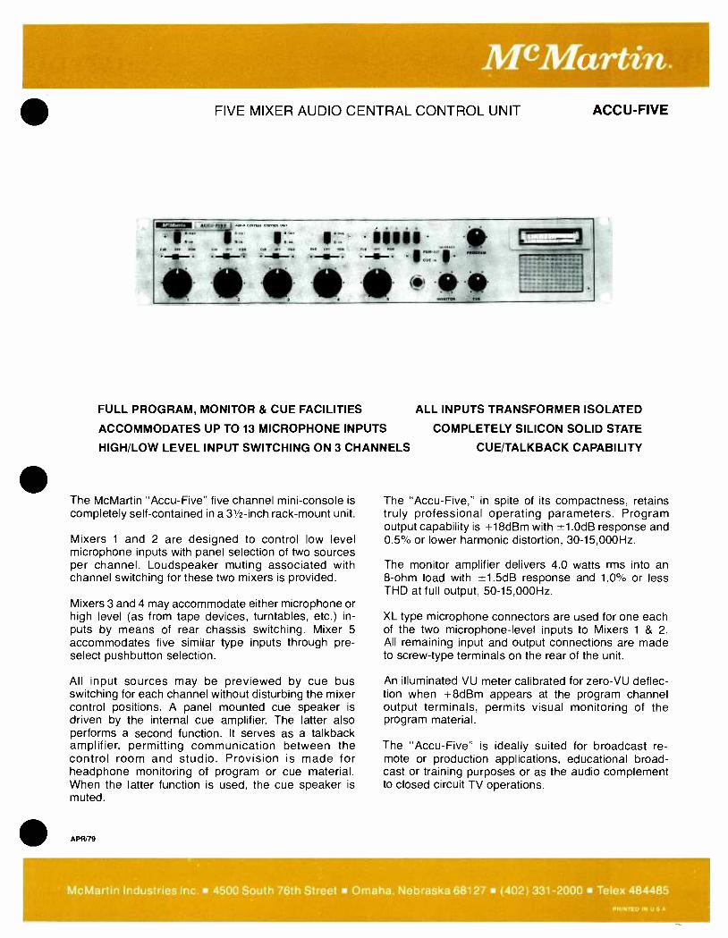
McMartin. FIVE MIXER AUDIO CENTRAL CONTROL UNIT ACCU -FIVE
FULL PROGRAM, MONITOR & CUE FACILITIES
ACCOMMODATES UP TO 13 MICROPHONE INPUTS
ALL INPUTS TRANSFORMER ISOLATED
COMPLETELY SILICON SOLID STATE
HIGH /LOW LEVEL INPUT SWITCHING ON 3 CHANNELS CUE /TALKBACK CAPABILITY
The McMartin "Accu- Five" five channel mini -console is completely self- contained in a 31/2 -inch rack -mount unit.
Mixers 1 and 2 are designed to control low level microphone inputs with panel selection of two sources per channel. Loudspeaker muting associated with channel switching for these two mixers is provided.
Mixers 3 and 4 may accommodate either microphone or high level (as from tape devices, turntables, etc.) in- puts by means of rear chassis switching. Mixer 5 accommodates five similar type inputs through pre- select pushbutton selection.
All input sources may be previewed by cue bus switching for each channel without disturbing the mixer control positions. A panel mounted cue speaker is driven by the internal cue amplifier. The latter also performs a second function. It serves as a talkback amplifier, permitting communication between the control room and studio. Provision is made for headphone monitoring of program or cue material. When the latter function is used, the cue speaker is muted.
APR/79
The "Accu- Five," in spite of its compactness, retains truly professional operating parameters. Program output capability is +18dBm with ±1.0dB response and 0.5% or lower harmonic distortion, 30- 15,000Hz.
The monitor amplifier delivers 4.0 watts rms into an 8 -ohm load with ±1.5dB response and 1.0% or less THD at full output, 50- 15,000Hz.
XL type microphone connectors are used for one each of the two microphone -level inputs to Mixers 1 & 2. All remaining input and output connections are made to screw -type terminals on the rear of the unit.
An illuminated VU meter calibrated for zero -VU deflec- tion when +8dBm appears at the program channel output terminals, permits visual monitoring of the program material.
The "Accu -Five" is ideally suited for broadcast re- mote or production applications, educational broad- cast or training purposes or as the audio complement to closed circuit TV operations.
McMartin Industries Inc. 4500 South 76th Street Omaha. Nebraska 68127 (402) 331 -2000 Telex 484485 PRINTED IN U S A
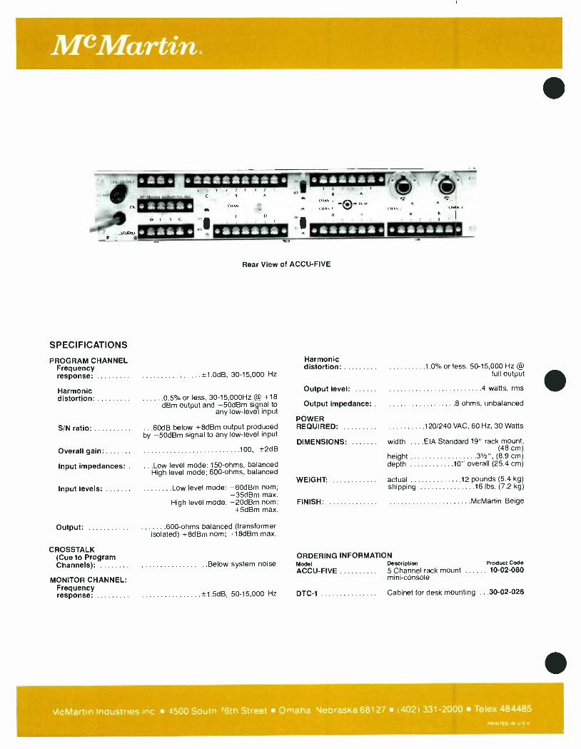
McMartin.
Rear View of ACCU -FIVE
SPECIFICATIONS
PROGRAM CHANNEL Harmonic Frequency distortion 1.0% or less, 50- 15,000 Hz @
response: *-1.0dB, 30-15,000 Hz full output
Harmonic distortion: 0.5% or less, 30- 15,000Hz @ +18
Output level: 4 watts, rms
dBm output and -50dBm signal to any low -level input
Output impedance: 8 ohms, unbalanced
POWER S/N ratio
Overall gain
.60dB below +8dBm output produced by -50dBm signal to any low -level input
100, i-2dB
REQUIRED:
DIMENSIONS:
120/240 VAC, 60 Hz, 30 Watts
width EIA Standard 19" rack mount, (48 cm)
height 31/2", (8.9 cm)
Input impedances:. ...Low level mode: 150 -ohms, balanced depth 10" overall (25.4 cm) High level mode; 600 -ohms, balanced
WEIGHT: actual 12 pounds (5.4 kg)
Input levels: Low level mode: -60dBm nom; shipping 16 lbs. (7.2 kg) -35dBm max.
High level mode: -20dBm nom; FINISH: McMartin Beige +5dBm max.
Output: 600 -ohms balanced (transformer isolated) +8dBm nom; +18dBm max.
CROSSTALK (Cue to Program ORDERING INFORMATION Channels): Below system noise Model Description Product Code
MONITOR CHANNEL: ACCU -FIVE 5 Channel rack mount 10 -02 -080
mini -console
Frequency response: ±1.5dB, 50-15,000 Hz DTC-1 Cabinet for desk mounting ...30 -02 -026
vlcMartin Inaustries Inc 4500 Soutn 76th Street Omaha Nebraska 68127 ( 402) 331 -2000 Telex 484485 PRINTED IN U S A

4- CHANNEL REMOTE AMPLIFIER
AC LINE /BATTERY OPERATION
RIAA PHONO OPTION - MIXERS #3 & #4
INBUILT TONE GENERATOR
DESCRIPTION
The McMartin Model BR -400 four -channel broad- cast remote amplifier incorporates extreme flexi- bility in a lightweight portable package and meets today's stringent requirements for high quality re- mote broadcasting.
Basically, a four -channel, balanced low- impedance microphone mixer, two of the mixing channels are field convertible to RIAA equalized phono operation, or alternatively, to accommodate balanced line - level inputs. In addition to +8 dBm 600 -ohm bal- anced output, visually- monitored by a front panel VU meter, a PA feed output with independent level control is provided. The BR -400 includes an internal 1000 Hz tone generator for presetting levels.
An isolated headphone amplifier with independent level gain control will accommodate low- as well as high- impedance headphones. This amplifier is
MAR76
BR-400
PA FEED
COMPACT, LIGHTWEIGHT
HEADPHONE AMPLIFIER
switchable to the incoming telephone line where used for remote "cueing.' purposes.
The BR -400 is normally powered from 115 Vac power: however, it is designed to house an internal battery power supply with automatic changeover to battery operation in the event of a power line fail- ure. The BR -400 dc supply consists of nine readily - available D -type cells. When rechargeable types are used. the BR -400 rovides the means of recharging these by switch operation. Battery life permits ap- proximately 100 hours of continuous operation, with half this time if the VU meter lamp. which may be switched off. is fused continuously.
The complete assembly is housed in a durable aluminum enclosure. Ready access to batteries and circuitry is afforded by the hinged top cover front panel construction.
McMartin Industries Inc. 4500 South 76th Street Omaha, Nebraska 68127 (402) 331 -2000 Telex 484485 PRINTED IN U S A
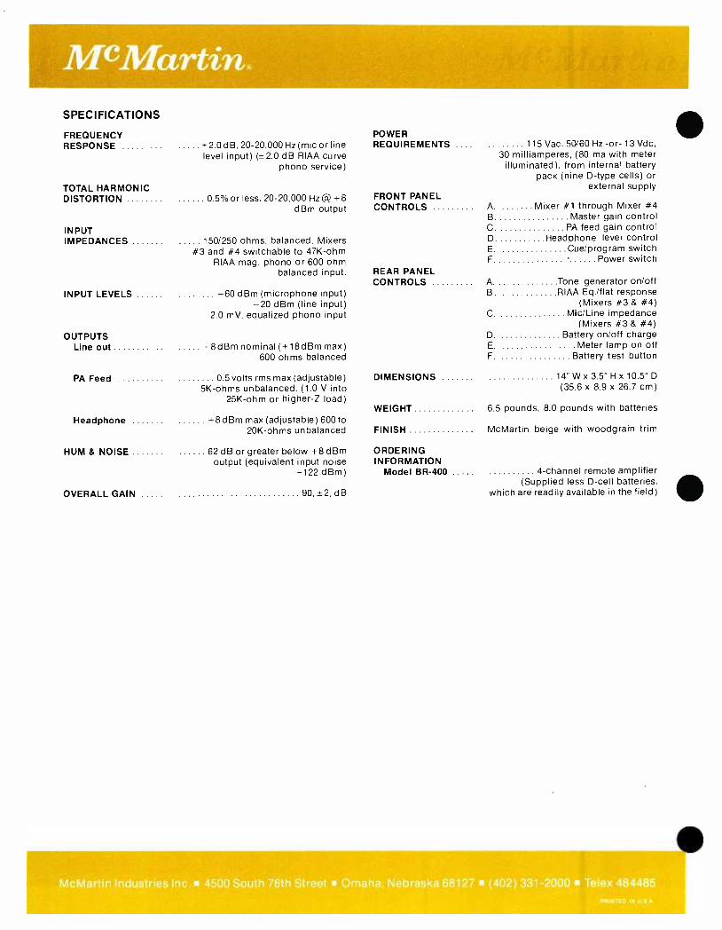
SPECIFICATIONS
FREQUENCY RESPONSE
TOTAL HARMONIC DISTORTION
INPUT IMPEDANCES
INPUT LEVELS
*20 dB, 20- 20,000Hz(micorline level input) ( ±2.0 dB RIAA curve
phono service)
0 5 %or less, 20- 20,000 Hz @ +8 dBm output
150/250 ohms, balanced. Mixers #3 and #4 switchable to 47K -ohm
RIAA mag. phono or 600 ohm balanced input.
-60 dBm (microphone input) -20 dBm (line input)
2.0 mV, equalized phono input
OUTPUTS Line out +8dBm nominal( +18dBm max)
600 ohms balanced
PA Feed
POWER REQUIREMENTS 115 Vac, 50/60 Hz -or- 13 Vdc,
30 milliamperes, (80 ma with meter illuminated), from internal battery
pack (nine D -type cells) or external supply
FRONT PANEL CONTROLS A. Mixer #1 through Mixer #4
B Master gain control C. PA feed gain control D Headphone level control E. Cue /program switch F. Power switch
REAR PANEL CONTROLS A Tone generator on /off
B. RIAA Eq. /flat response (Mixers #3 & #4)
C. Mic /Line impedance (Mixers #3 & #4)
D. Battery on /off charge E. Meter lamp on off F. Battery test button
0 5 volts rms max (adjustable) DIMENSIONS 5K -ohms unbalanced. (1.0 V into
25K -ohm or higher -Z load)
Headphone +8dBm max (adjustable) 600 to 20K -ohms unbalanced
HUM & NOISE 62 dB or greater below +8 dBm output (equivalent input noise
-122 dBm)
OVERALL GAIN 90, +2, dB
14 "Wx3.5 "Hx10.5 "D (35.6 x 8.9 x 26.7 cm)
WEIGHT 6.5 pounds, 8.0 pounds with batteries
FINISH McMartin beige with woodgrain trim
ORDERING INFORMATION
Model BR -400 4- channel remote amplifier (Supplied less D -cell batteries,
which are readily available in the field)
McMartin Industries Inc. 4500 South 76th Street Omaha, Nebraska 68127 (402) 331 -2000 Telex 484485 PRINTED IN U S A
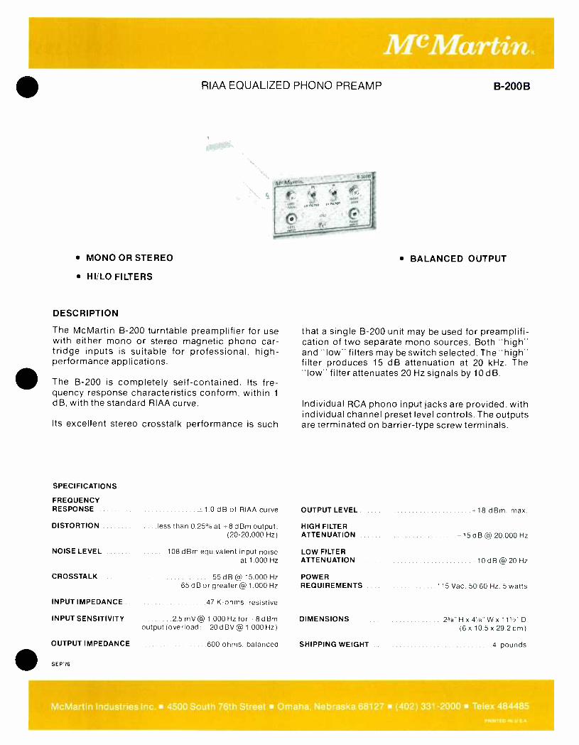
RIAA EQUALIZED PHONO PREAMP B -200B
Meiy}ortia.
MONO OR STEREO
HI /LO FILTERS
DESCRIPTION
The McMartin B -200 turntable preamplifier for use with either mono or stereo magnetic phono car- tridge inputs is suitable for professional, high - performance applications.
The B -200 is completely self- contained. Its fre- quency response characteristics conform, within 1
dB, with the standard RIAA curve.
Its excellent stereo crosstalk performance is such
9-2008
BALANCED OUTPUT
that a single B -200 unit may be used for preamplifi- cation of two separate mono sources. Both "high" and "low" filters may be switch selected. The "high- filter produces 15 dB attenuation at 20 kHz. The "low" filter attenuates 20 Hz signals by 10 dB.
Individual RCA phono input jacks are provided, with individual channel preset level controls. The outputs are terminated on barrier -type screw terminals.
SPECIFICATIONS
FREQUENCY RESPONSE 1.0 dB of RIAA curve OUTPUT LEVEL +18 dBm. max.
DISTORTION ....less than 0.25% at -8dBm output, (20- 20,000 Hz)
HIGH FILTER ATTENUATION -15 dB @ 20,000 Hz
NOISE LEVEL 108 dBm equivalent input noise LOW FILTER at 1,000 Hz ATTENUATION -10 d B @ 20 Hz
CROSSTALK 55 dB @ 15.000 Hz POWER 65 dB or greater @ 1,000 Hz REQUIREMENTS 115 Vac. 5060 Hz. 5 watts
INPUT IMPEDANCE 47 K -ohms. resistive
INPUT SENSITIVITY 25 mV@ 1.000 Hz for *8dBm output (overload: - 20dBV@ 1.000 Hz)
DIMENSIONS 23'9" H x 41/2" W x 111/2" D (6x 10.5x29.2cm)
OUTPUT IMPEDANCE 600 ohms. balanced SHIPPING WEIGHT 4 pounds
SEP 76
McMartin Industries Inc. 4500 South 76th Street Omaha, Nebraska 68127 (402) 331 -2000 Telex 484485
PRINTED IN U S A

MIXER/PREAMPLIFIER
FOUR MICROPHONE & ONE PROGRAM INPUT CHANNEL
BUILT IN TONE GENERATOR
The McMartin Model MX -5 five -channel mixer /pre- amplifier is a high -quality, high performance unit offering excellent flexibility in the choice of input mixing functions required either for subsequent amplification in sound distribution systems, or for premixing for recording equipment with "line- level" input requirements.
Four balanced, low -level, low impedance inputs, ter- minated in female, XL -type connectors accommo- date 150 ohm microphones. Any of these inputs, by change in internal jumper -plug orientation, may be modified to accept high- impedance, unbalanced microphones. In addition, two of the inputs may be modified for magnetic phono, RIAA equalized, ser- vice. By operation of a rear -panel slide switch, the first microphone input channel is converted to a
1000 -Hertz tone generator. This permits prechecking of overall system operating levels.
The program -level input mixer accepts either low impedance balanced sources through rear -chassis screw terminals, or unbalanced 25K -ohm input through an RCA phono jack.
The level of the premixed inputs is controlled by a front -panel Master gain control. Output level from the MX -5 is monitored by an illuminated VU meter,
JUN /78
MX-5
OPERABLE FROM EXTERNAL DC SUPPLY
TWO MIC CHANNELS CONVERTIBLE TO RIAA MAG PHONO SERVICE
with front -panel switching for "zero VU" meter indication of either +4 dBm or +8 dBm line level output levels.
600 -ohm, transformer -isolated, balanced line output appears on rear -panel screw terminals. In addition, microphone level, at nominally 40 dBm, is termi- nated in a male XL -type connector; unbalanced 5K- ohm output appears on an RCA phono jack; and an isolated +18 dBm signal is brought out to a rear, standard 1/4-inch phone jack for headphone monitor- ing. Where desired, the MX -5 may be powered from a 36 -volt 70- milliampere, external dc power supply -in lieu of the normal built -in MX -5 power supply which operates from a 120 Vac, 60 Hz power source.
The versatility of the MX -5 operation is enhanced by its compact packaging. The MX -5 is completely self - contained in an attractively- finished blue and silver gray, aluminum housing which is only 123/4" wide, 71/2" deep, with a low 23/4" profile.
The MX -5 is a quality instrument, using high -grade, long -life components, most of which are mounted on a single grade G -10, glass epoxy base, printed circuit board for ease of maintenance and servicing.
The MX -5 satisfies the requirement for professional, high quality and reliability sound installations.
McMartin Industries Inc. 4500 South 76th Street Omaha, Nebraska 68127 (402) 331 -2000 Telex 484485
PRINTED IN U S A

-41; 410 e.
I1O4LO 1EPOMONE LIITO Pawl
IIDV SO N1 W477I
NNP
NEMOTEPOVRN 34 V OC
(
WNW OUTPUT N II
UNSAL INPUT M l I O !
F:, Fmr w1
**it *AM CLAPS P UONN WPM ONLY
CAUiION -ío wEYINr ptcTNCU WOW. . oo,ol ,[NOPP w.e, «o we. le,vKlmot WPM POW PN, IP,VWNO To CuPLIPID PE,vIL PEMOOßt.
IOC LEVEL WC MONO WC MONO MICO OUTPUT
Rear View of MX -5
SPECIFICATIONS INPUTS
Microphone Four (4) Total: Channel #1 switchable to operate as 1 kHz tone
generator. Channels #3 and #4 switchable to RIAA equalized magnetic
phono service, by simple internal plug reversal
Program One
INPUT IMPEDANCES Mic Channels ...50 -150 ohms balanced; switchable
to 25K -ohms unbalanced by internal jumper plug. Channels #3 and #4
switchable to 47K -ohms for magnetic phono service by internal
plug reversal
Program Channel .. 600 ohms, balanced (matching) 10K -ohms, balanced (bridging); or 25K -ohms, unbalanced (bridging)
INPUT LEVELS Mic Channels -60 dBV balanced; -28dBV
overload point; -55 dBV, unbalanced. Channels 3 & 4 in magnetic
phono mode: 2 millivolts @ 1 kHz
Program Channel 600 ohms matching; or10K -ohm bridging; or 100 millivolts,
25K -ohms, unbalanced FREQUENCY RESPONSE
Mic Channels
Program Channel
+1 0 dB, 50- 20,000 Hz, ±2.0 dB, 20- 20,000 Hz; Channels #3 & 4 in magnetic phono mode.
within 2.0 dB of RIAA curve
+0 5 dB, 50-20,000 Hz; ±1.0 dB, 20-20,000 Hz
NOISE Mic Channels ..65dB (wide band) and 72dB(with
15 kHz low pass filter) below +8 dBm output, with 3.0 mV input signal.
Equivalent Input Noise: -122 dBm. Channels #3 & 4 in magnetic
phono mode: -55 dB.
Program Channel .. ....80 dB (wide band) and 85 dB (w/15 kHz LP filter) below +18 dBm output.
OUTPUT IMPEDANCES & LEVELS
TOTAL HARMONIC & INTERMODULATION DISTORTION
FRONT PANEL CONTROLS
FRONT PANEL SWITCHES
REAR PANEL SWITCHES:
REAR PANEL TERMINATIONS
POWER REQUIREMENTS
DIMENSIONS
SHIPPING WEIGHT
FINISH
A) 600 ohms balanced: +4 dBm or +8 dBm nominal by front panel switching; +18dBm maximum into 600 -ohm load. B) 5K -ohms, unbalanced (isolated) @
3.0 volts. rms C) 50/150 balanced: -45 dBm D) Headphone jack: 600 ohms, unbal-
anced (isolated) @ +18 dBm
0.5% or less, 20- 20,000 Hz @ +8 dBm output level; 1.0% or less,
20- 20,000 Hz @ +18 dBm output level
Mic #1 /tone generator, Mic #2 level, Mic #3 & 4/equalized phono
levels, Program level and Master gain
Output level, +4 or +8 dBm; power on /off.
Mic #1 /Tone generator.
Channel #1 to #4 inputs, Cl F connectors; Mic Level Output, C1M connector; Balanced program input
and balanced 600 -ohm output, screw terminals; unbalanced program input
and 5K -ohm unbalanced output, RCA phono jack; 36 -volt dc external power, two -pin Cinch Jones socket.
105/125 Vac, 50/60 Hz, 3 watts (Fuse: I/S ampere, slow -blow)
123/4" (32.4 cm) wide 23/4" (7.0 cm) height 73/4" (19.7 cm) deep
6 pounds
McMartin blue and silver gray
ORDERING INFORMATION Model Description - Product Code
MX -5 5 channel mixer /preamplifier ..20 -04 -045
McMartin Industries Inc. 4500 South 76th Street Omaha, Nebraska 68127 (402) 331 -2000 Telex 484485 PRINTED IN U S A
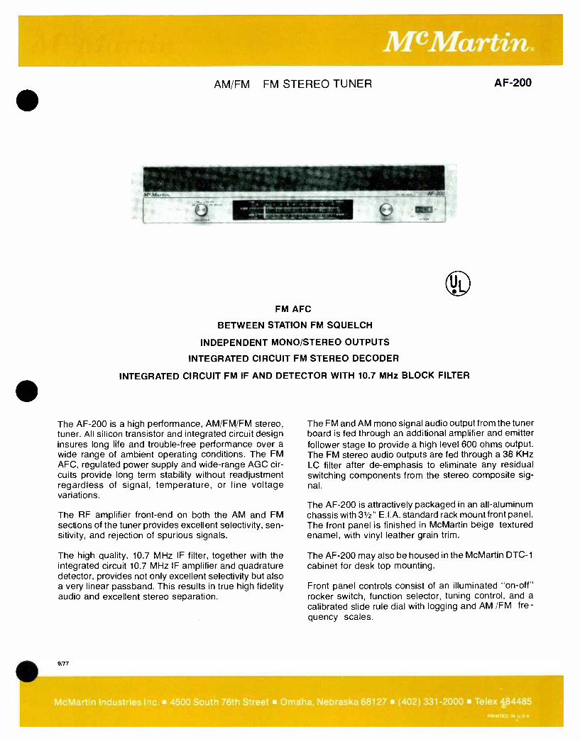
AM /FM FM STEREO TUNER AF -200
FM AFC
BETWEEN STATION FM SQUELCH
INDEPENDENT MONO /STEREO OUTPUTS
INTEGRATED CIRCUIT FM STEREO DECODER
INTEGRATED CIRCUIT FM IF AND DETECTOR WITH 10.7 MHz BLOCK FILTER
The AF -200 is a high performance, AM /FM /FM stereo, tuner. All silicon transistor and integrated circuit design insures long life and trouble -free performance over a wide range of ambient operating conditions. The FM AFC, regulated power supply and wide -range AGC cir- cuits provide long term stability without readjustment regardless of signal, temperature, or line voltage variations.
The RF amplifier front -end on both the AM and FM sections of the tuner provides excellent selectivity, sen- sitivity, and rejection of spurious signals.
The high quality, 10.7 MHz IF filter, together with the integrated circuit 10.7 MHz IF amplifier and quadrature detector, provides not only excellent selectivity but also a very linear passband. This results in true high fidelity audio and excellent stereo separation.
ern
The FM and AM mono signal audio output from the tuner board is fed through an additional amplifier and emitter follower stage to provide a high level 600 ohms output. The FM stereo audio outputs are fed through a 38 KHz LC filter after de- emphasis to eliminate any residual switching components from the stereo composite sig- nal.
The AF -200 is attractively packaged in an all- aluminum chassis with 31/2" E.I.A. standard rack mount front panel. The front panel is finished in McMartin beige textured enamel, with vinyl leather grain trim.
The AF -200 may also be housed in the McMartin DTC -1
cabinet for desk top mounting.
Front panel controls consist of an illuminated "on -off" rocker switch, function selector, tuning control, and a
calibrated slide rule dial with logging and AM /FM fre- quency scales.
McMartin Industries Inc. 4500 South 76th Street Omaha, Nebraska 68127 (402) 331 -2000 Telex 484485 PRINTED IN U S A
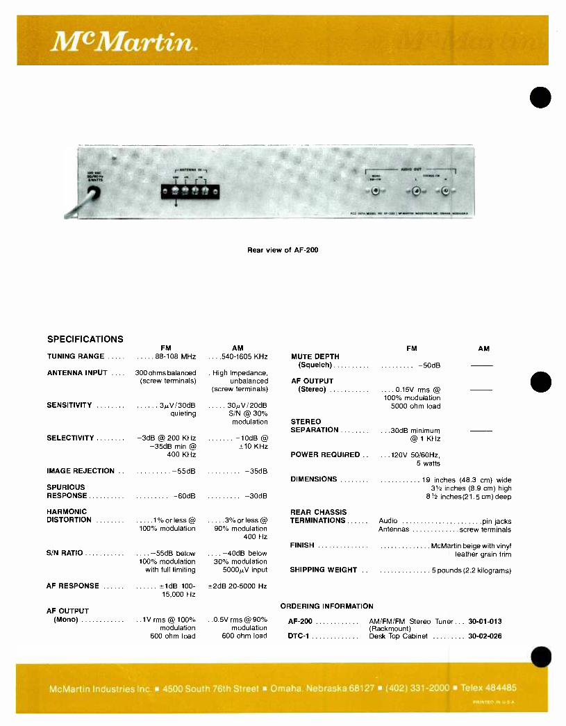
McMartin.
SPECIFICATIONS
1,1
Rear view of AF -200
FM AM FM AM TUNING RANGE 88 -108 MHz . . . .540-1605 KHz MUTE DEPTH
(Squelch) -50dB ANTENNA INPUT .... 300 ohms balanced
(screw terminals) . High Impedance,
unbalanced AF OUTPUT (screw terminals) (Stereo) 0.15V .... rms @
100% modulation SENSITIVITY 30/30dB
quieting 300/20dB S/N @ 30% modulation STEREO
5000 ohm load
SEPARATION ...30dB minimum @ 1 KHz SELECTIVITY -3dB @ 200 KHz -10dB @
-35dB min @ ±10 KHz 400 KHz POWER REQUIRED .. ...120V 50 /60Hz,
5 watts IMAGE REJECTION .. -55dB -35dB
DIMENSIONS 19 inches (48.3 cm) wide SPURIOUS 31/2 inches (8.9 cm) high RESPONSE -60dB -30dB 8'/ inches (21. 5 cm) deep
HARMONIC REAR CHASSIS DISTORTION 1% or less @ 3% or less @ TERMINATIONS Audio pin jacks
100% modulation 90% modulation Antennas screw terminals 400 Hz
FINISH McMartin beige with vinyl S/N RATIO .... -55dB below .... -40dB below leather grain trim
100% modulation 30% modulation with full limiting 5000µV input SHIPPING WEIGHT .. 5 pounds (2.2 kilograms)
AF RESPONSE 1dB 100- ±2dB 20-5000 Hz 15,000 Hz
ORDERING INFORMATION AF OUTPUT
(Mono) ..1V rms @ 100% ..0.5V rms @ 90% AF -200 AM /FM /FM Stereo Tuner ... 30 -01 -013 modulation modulation (Rackmount)
600 ohm load 600 ohm load DTC -1 Desk Top Cabinet 30 -02 -026
McMartin Industries Inc. 4500 South 76th Street Omaha. Nebraska 68127 (402) 331 -2000 Telex 484485 PRINTED IN U S A

TRANSISTOR AMPLIFIERS, 10 -15 watts
11.1 ----.-------
LT -80C shown
10 -15 WATTS RMS POWER OUTPUT
LOW PROFILE 31/2" HIGH
BALANCED LOW Z MICROPHONE INPUT
MICROPHONE /PROGRAM INPUTS
The LT -80C and 108C are conservatively rated wide power- bandwidth 10 -15 watt rms audio amplifiers. They are designed for system sound applications requiring one microphone and one program source. As many as twenty speakers (tapped 1/2 watt) may be driven from the 25 or 70.7 volt balanced output, or a single four -ohm speaker system may be driven to a full 15 watts rms from the unbalanced output.
The microphone input is standard balanced low impe- dance 50/150 ohms with -60 dBm input sensitivity and 30 dB dynamic range. The microphone input is
also convertible to high impedance unbalanced input. A three pin XL female connector is provided for micro- phone termination on the LT -80C. Screw terminal input connection is provided on the 108C.
The LT -80C features a fully electronic page mute system. Actuation of a simple single pole, single -throw switch closure at the microphone location automatically mutes the program channel and energizes the microphone channel for paging purposes. This switching operation is completely free of clicks and pops.
The program channel input is unbalanced 25K ohms with 300 millivolt sensitivity. An optional plug -in trans-
FEB/79
SP
LT-80C 108C
BUILT-IN ELECTRONIC MUTING (LT-80C)
ELECTRONIC SHORT CIRCUIT PROTECTION
ALL SILICON DESIGN
SINGLE /DUAL RACK MOUNT OPTIONS
former card, Model MT -3, provides for balanced bridg- ing input with sensitivity of -10 dBm. Input termina- tion is either screw terminals or pin connector for the unbalanced inputs, and screw terminals for balanced input.
A 20 dB treble -cut tone control is provided for high -end roll off of the program channel. The microphone input is wired for 10 dB bass roll -off for crisp voice quality and may be field modified for flat response. On the LT -80C, the tone control is on the front panel and in the 108C, it is a front access, recessed screwdriver adjusted control. An optional gain limit control may be field installed to limit the range of the front panel controls.
Screw terminal output termination allows for connection of unbalanced loads from 4 to 16 ohms. Balanced 25 volt (62.5 ohm) and 70.7 volt (500 ohm) outputs are also provided. Continuous short circuit operation of any output will not damage transistors or the power supply.
Attractive, low profile packaging, with the capability of single or dual -unit optional rack mounts, make the LT-
80C and 108C even more flexible in application.
McMartin Industries Inc. 4500 South 76th Street Omaha, Nebraska 68127 (402) 331 -2000 PRINTED IN U S A '

McMartin.
It I MOM
.COQ OYTN. 1. t. WATT) -- CMU. 22.1.114
.w.
r117.1 .7. 1"
,..,a.wa *it it a****** 011 /NH. NW
O+.í10I ar.r.n, /.ew....... un. e,w.. w.s,.ra
SPECIFICATIONS
POWER OUTPUT:
Rear View, LT -80C
10 watts rms -16 ohms unbalanced; 25/70.7 volt
balanced line 12.5 watts rms -8 ohms
unbalanced 15 watts rms -4 ohms
unbalanced FREQUENCY RESPONSE: ± 1 dB, 50- 15,000 Hz
DISTORTION 1% or less, 50- 20,000 Hz at 12.5W output
HUM & NOISE: MIC: 60 dB below 10 watts output PGM: 70 dB below 10 watts output
OUTPUTS: 4/8/16 ohms unbalanced; 25/70.7 volt balanced line
PROGRAM /LINE INPUT: 25K -ohm unbalanced, 600 ohms
balanced with optional MT -3 plug -in card
PROGRAM /LINE SENSITIVITY: 300 millivolts, 25K ohm
unbalanced input. -10 dBm (balanced 10K ohm
bridging with MT-3 p plug -in card.) 0 dBm (balanced 600 -ohm matching
with MT -3 plug -in card.) OPERATING TEMPERATURE: to 150 °F (66 °C)
OVERLOAD PROTECTION: Solid state protection circuit
samples output stage current and disables input signal during excessive loading condition
POWER REQUIRED: 120 Vac, 50/60 Hz, 30 watts
(Primary taps for 105 and 125 Vac)
MIC INPUT. 150 ohms balanced
MIC TERMINATION: LT -80C XL Connector 108C Screw terminals
ron.. °unur n n WATTS 4.f. *Man } U Ì nr ... Á**s*s11,1141
....,, r`1 O s**
,.u,.. r.c ../«w. WW. 1 i
ion I aaMsuW .nMInY.. be. e.......r.nww.
Rear View, 103C
MUTING: LT -80C Electronic muting of microphone
and program circuits 108C None
RESPONSE EQUALIZATION:
LT -80C Front panel treble cut tone control ( -20 dB at 20 kHz)
Microphone bass cut ( -10 dB at 50 Hz). Flat response possible by
change of one capacitor.
108C Front panel screwdriver adjustment treble cut tone control ( -20 dB at 20 kHz); Microphone bass cut ( -10 dB
at 50 Hz). Flat response possible by change of one capacitor
DIMENSIONS height 31/2" (8.9 cm) width 81/2" (21.6 cm) depth 71/4" (18.4 cm)
FINISH: McMartin Blue and gray
WEIGHT: actual 4 lbs. (1.8 kg) shipping 7 lbs. (3.2 kg)
OPTIONAL ACCESSORIES:
MT -3 Plug -in program channel matching/bridging line input card
MRP -3 Single unit rack mounting kit height 31/2" (8.9 cm) width 19" (48.3 cm)
MRP -4 Dual unit rack mounting kit (two units racked side by side) height 31/2" (8.9 cm) width 19" (48.3 cm)
ORDERING INFORMATION MODEL DESCRIPTION PRODUCT CODE LT -80C 10 -15 watt amplifier 20 -04 -008 108C 10 -15 watt amplifier 20 -04 -001 MT -3 line input card 20 -04 -043 MRP -3 single rack mounting kit 30 -02 -023 MRP-4 dual rack mount kit 30 -02 -024
McMartin Industries Inc. 4500 South 76th Street Omaha, Nebraska 68127 (402) 331 -2000 Telex 484485 PRINTED IN U S A

McMartin. 25 WATT UNIVERSAL AMPLIFIER
ONE LOW -Z MIC INPUT
ONE LOW -Z MIC /MAG PHONO INPUT
DESK MOUNT
TONE COMPENSATION
EXCELLENT PERFORMANCE
ONE HI -Z UNBALANCED PROGRAM INPUT CONVERTIBLE TO LOW -Z BALANCED
The McMartin LT -252B is a 25 watt rms silicon solid state amplifier designed for multiple input applica- tions. It is completely self- contained and housed in an attractive cabinet suitable for desk top use.
The LT -252B accommodates two 150 ohm balanced microphone inputs through XLR type connectors and a medium level 25 k ohm unbalanced program input. The program input can accommodate medium level, 600 ohm matching or 10 k ohm bridging signal sources by addition of the optional plug -in MT -3
module.
DEC /80
LT-252B
Front panel tone compensation controls permit ± 15 dB treble and bass boost or cut.
The LT -252B is designed to feed 25 or 70.7 volt balanc- ed; or 4 or 8 ohm unbalanced loads. Where applicable, direct coupled 4 ohm loads by- passing the output transformer provide ± 10 dB frequency response from 50 to 20,000 Hz.
The LT -252B is conservatively designed to provide highly -reliable continuous service.
McMartin Industries Inc. 4500 South 76th Street Omaha, Nebraska 68127 (402) 331 -2000 Telex 484485
PRINTED IN U S A
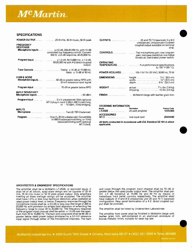
McMartin.
SPECIFICATIONS
POWER OUTPUT
FREQUENCY RESPONSE Microphone Inputs .
Program Input
Tone Controls
HUM & NOISE Microphone Inputs
Program Input
INPUT SENSITIVITY Microphone Inputs ...
Program Input
INPUTS Microphone
Program
25 W rms, 35 W music, 50 W peak
+ 2.0 dB, 200- 20,000 Hx, with 10 dB controlled low frequency roll-off. Convert-
ible to ± 21 dB response, 40- 20,000 Hz.
± 1.0 dB, 50- 10,000 Hz; ± 1.0 dB, 50-20,000 Hz with 4 0 direct -coupled
output.
Treble: ± 15 dB at 15,000 Hz. Bass: ± 15 dB at 50 Hz.
60 dB or greater below RPO with 30 mV reference input signal
70 dB or greater below RPO
-60dBm
04 V unbalanced. With optional MT -3 plug -in card: 0 dBm, 600 0 matching;
or -10 dBm, 10 k12 bridging.
Two (2) 150 S2 balanced.
One (1), 25 k12 unbalanced. Convertible to 600 0 balanced matching, or 10 kO
balanced briding (with optional MT -3 card).
ARCHITECTS'S & ENGINEERS' SPECIFICATIONS
The amplifier shall be a McMartin LT-252B, or approved equal. It shall be of all silicon, solid state design and be capable of 25 W rms, 35 W rms music or 50 W peak power output. Only amplifiers meeting all three wattage ratings will be accepted. The amplifier shall have 1.0% or less total harmonic distortion when operated at rated power output level, or below. Frequency response through the microphone inputs shall be ± 2.0 dB or less over the range of 200 to 20,000 Hz with provision by simple field alteration of extending the frequency range to cover 40 to 20,000 Hz. The frequency response of the program input channel shall be within ± 1.0 dB over the spec- trum from 50 to 10,000 Hz. The hum and noise level shall be 60 dB or greater below rated power output produced by a 3.0 mV reference input signal through either of the microphone channels. The hum
OUTPUTS 25 and 70.7 V balanced; 4 or 8 0 unbalanced. Unbalanced 40 direct
coupled output available on terminal strip.
CONTROLS .. Two microphone gain; one program gain; one bass boost/cut; one treble boost/cut; illuminated power switch.
OPERATING TEMPERATURE Full performance specifications
to 150° F (65 ° C).
POWER REQUIRED . . .... 105 -115/115 -125 VAC, 50/60 Hz, 75 W
DIMENSIONS height 3'/2 "(8.9cm) width 12 "(30.5 cm) depth 83/4 " (22.3 cm)
WEIGHT actual 71/2 lbs. (3.4 kg) shipping 10 lbs. (4.5 kg)
FINISH .. McMartin beige with leather grain trim
ORDERING INFORMATION Model Description LT-252B 25 watt amplifier
ACCESSORIES MT -3 line input card
Froduct Code 10- 05-003
20- 04-043
All tests conducted in accordance with EIA Standard SE-101-A where applicable.
and noise through the program input channel shall be 70 dB or greater below the rated power output level. The amplifier shall per- mit ±5 dB boosticut at 15,000 Hz and 50 Hz by means of treble /bass front panel controls respectively. The amplifier shall have outputs of 4 and 8 12 unbalanced and 25 and 70 V balanced configuration. Rear panel termination of a 4 0 direct coupled out- put shall be provided.
The amplifier shall be listed by Underwriters Laboratories
The amplifier front panel shall be finished in McMartin beige with leather grain trim, self- contained in an aluminum enclosure of bronze metallic finish, suitable for desk top use.
McMartin Industries Inc. 4500 South 76th Street Omaha, Nebraska 68127 (402) 331 -2000 Telex 484485 PRINTED IN U S A

25 WATT POWER AMPLIFIER
M.Martìn
LT-250C
LESS THAN 1% DISTORTION 40 - 20,000 Hz FULL POWER FREQUENCY RESPONSE
CURRENT SENSING OVERLOAD PROTECTION BALANCED 70.7 & 25 VOLT OUTPUTS
BASS CUT SWITCH FOR HORN SPEAKER USE UNBALANCED 4, 8, & 16 OHM OUTPUTS
The LT -250C is a 25 watt rms silicon solid -state transistorized amplifier designed for low distortion output over a full power bandwidth of 40- 20,000 Hz. The low frequency response of the amplifier can be extended to 20 Hz when operated with the field convertible direct coupled output.
This basic amplifier utilizes plug- connected circuit board construction, with power transistors and power supply components mounted and placed for maximum accessibility. Computer grade capaci- tors, and conservatively -rated transformers con- tribute to maximum performance and reliability.
The LT -250C accommodates either an unbalanced high impedance or a 600 ohm balanced program input. The balanced input utilizes a transformer, factory wired for 600 ohms matching. It is easily field modified for 10K ohms bridging without addi- tional components.
The front panel program gain control may be trans- ferred to the rear panel where that location is pre- ferred.
JANI79
The LT -250C amplifier features an overload pro- tection, fast -acting current -limiting electronic circuit that automatically disables amplifier drive should a potentially harmful overload occur.
The LT -250C amplifier has 70.7 V and 25 V balanced outputs, plus 4, 8, and 16 ohm unbalanced outputs. Input and output connections are on convenient screw terminals.
The amplifier output may be directly coupled to an 8 ohm load. When so operated, the low -end frequency response is extended to 20 Hz.
A rear -panel mounted bass cut switch tailors the amplifier response (14 dB down at 100Hz) in instal- lations where horn speakers are utilized.
The LT -250C, styled in McMartin beige with com- plementary leather grain accent, is designed for direct mounting in a 19" rack. An attractive desk top cabinet is available.
LT -250C - continuing the excellence in solid - state amplifiers pioneered by McMartin Industries.
McMartin Industries Inc. 4500 South 76th Street Omaha, Nebraska 68127 (402) 331 -2000 Telex 484485 PRINTED IN U S A

McMartin.
SPECIFICATIONS POWER OUTPUT 25 watts rms
35 watts music 50 watts peak
FREQUENCY RESPONSE *1 dB 40- 20,000 Hz
±1 dB 20- 20,000 Hz direct coupled output
DISTORTION Less than 1% (40- 20,000 Hz) at RPO and below
HUM AND NOISE (Program) 85 dB below RPO
PROGRAM INPUT Unbalanced 25K ohms, and balanced 10K ohms bridging or
balanced 600 ohms matching INPUT
SENSITIVITY 0.4 volts unbalanced 0 dBm 600 ohms matching
-10 dBm 10K ohms bridging
OUTPUTS Balanced 70.7 volts and 25 volts; Unbalanced 4, 8, and 16 ohms;
Unbalanced 8 ohm direct output
CONTROLS Program gain; power on /off
ARCHITECTS' & ENGINEERS' SPECIFICATIONS
The amplifier shall be a McMARTIN LT -250C, or approved equal. It shall be of all silicon solid -state construction and capable of 25 watts rms, 35 watts music, 50 watts peak power output. Only amplifiers meeting all three wattage ratings will be ac- cepted. The amplifier shall have less than 1% distortion at rated output and below. The frequency response shall be ±1 dB 40- 20,000 Hz with a transformer output, and ±1 dB 20- 20,000 Hz with a field strappable direct 8 -ohm output. The amplifier noise shall be at least 85 dB below signal at the rated power output. The amplifier shall be designed to operate con- tinuously on line voltages of 105 to 125 Volts, 50/60 Hz over a temperature range of 0° to 150° F. ( -18° C to 65° C). The ampli- fier shall be equipped with a current sensing overload protec- tion circuit that will remove audio drive from the amplifier should an overload or short circuit develop. This protection circuit shall restore the amplifier in one millisecond when the short or overload is removed.
Only amplifiers offering this type of protective circuits shall be acceptable.
The amplifier shall be capable of accepting either a balanced or unbalanced program input without the installation of addi- tional equipment. A transformer shall be permanently installed in the amplifier to accommodate 10K ohm and 600 ohm bal- anced line inputs, both matching and bridging shall be avail- able. Screw terminals shall be provided for balanced inputs.
POWER REQUIRED
DIMENSIONS
WEIGHT
OPERATING TEMPERATURE
105 -115 Vac or 115 -125 Vac 50/60 Hz 75 watts
height 31/2" (8.9 cm) width 19" (48.3 cm) depth 53/4" (14.5 cm)
actual 11 lbs (5 kg) shipping 13 lbs (5.9 kg)
Full performance to 150° F (65° C)
FINISH McMartin beige with leather grain trim
ORDERING INFORMATION
Modal Description LT-250C 25 watt power amplifier
ACCESSORIES DTC -1 Desk top cabinet
height 31/2" ( 8.9 cm) width 191/4" (48.9 cm) depth 91/4' (23.5 cm)
Product Cods 30 -01 -002
30 -02 -026
All tests conducted in accordance with EIA Standard SE -101 -A where applicable.
The amplifier shall have outputs of 4, 8, and 16 ohms unbal- anced, and 70.7 V and 25 V balanced. The balanced circuits shall be capable of being balanced to ground, or floating bal- anced. A bass cut switch shall be provided that shall attenuate the bass in the output. A 14 dB cut at 100 Hz will be required. Screw type terminals shall be provided for all outputs. A direct coupled 8 ohm output shall be available by strapping the rear panel connector, and the direct coupled output shall provide extended low frequency response down to 20 Hz.
The amplifier shall be equipped with a program gain control, and an illuminated power on /off switch.
The amplifier shall have an unswitched 115 volt 3 wire grounded accessory outlet.
The amplifier shall be listed by Underwriters Laboratories and the Canadian Standards Association.
The amplifier shall be McMartin beige with a leather grain trim.
The amplifier shall be capable of being directly mounted in a
19" relay rack, and shall be supplied with, capable of being housed in a complementary appearing desk top housing.
McMartin Industries Inc. 4500 South 76th Street Omaha, Nebraska 68127 (402) 331 -2000 Telex 484485 PRINTED IN U S A
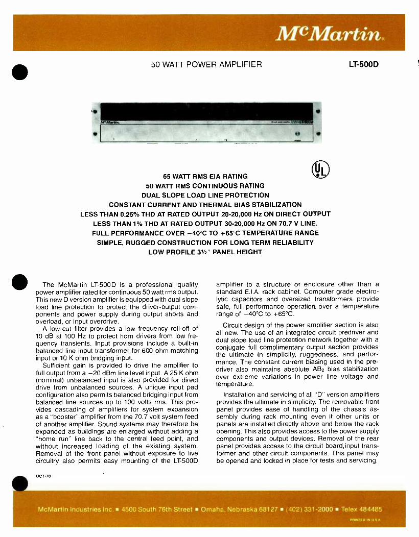
M"MartinR 50 WATT POWER AMPLIFIER
65 WATT RMS EIA RATING
50 WATT RMS CONTINUOUS RATING
DUAL SLOPE LOAD LINE PROTECTION CONSTANT CURRENT AND THERMAL BIAS STABILIZATION
LESS THAN 0.25% THD AT RATED OUTPUT 20- 20,000 Hz ON DIRECT OUTPUT
LESS THAN 1% THD AT RATED OUTPUT 30- 20,000 Hz ON 70.7 V LINE.
FULL PERFORMANCE OVER -40 °C TO +65 °C TEMPERATURE RANGE
SIMPLE, RUGGED CONSTRUCTION FOR LONG TERM RELIABILITY LOW PROFILE 31/2" PANEL HEIGHT
The McMartin LT -500D is a professional quality power amplifier rated for continuous 50 watt rms output. This new D version amplifier is equipped with dual slope load line protection to protect the driver -output corn - ponents and power supply during output shorts and overload, or input overdrive.
A low -cut filter provides a low frequency roll -off of 10 dB at 100 Hz to protect horn drivers from low fre- quency transients. Input provisions include a built -in balanced line input transformer for 600 ohm matching input or 10 K ohm bridging input.
Sufficient gain is provided to drive the amplifier to full output from a -20 dBm line level input. A 25 K ohm (nominal) unbalanced input is also provided for direct drive from unbalanced sources. A unique input pad configuration also permits balanced bridging input from balanced line sources up to 100 volts rms. This pro- vides cascading of amplifiers for system expansion as a "booster" amplifier from the 70.7 volt system feed of another amplifier. Sound systems may therefore be expanded as buildings are enlarged without adding a "home run" line back to the central feed point, and without increased loading of the existing system. Removal of the front panel without exposure to live circuitry also permits easy mounting of the LT -500D
OCT/78
LT-500D
amplifier to a structure or enclosure other than a
standard E.I.A. rack cabinet. Computer grade electro- lytic capacitors and oversized transformers provide safe, full performance operation. over a temperature range of -40 °C to +65 °C.
Circuit design of the power amplifier section is also all new. The use of an integrated circuit predriver and dual slope load line protection network together with a
conjugate full complimentary output section provides the ultimate in simplicity, ruggedness, and perfor- mance. The constant current biasing used in the pre - driver also maintains absolute AB2 bias stabilization over extreme variations in power line voltage and temperature.
Installation and servicing of all "D" version amplifiers provides the ultimate in simplicity. The removable front panel provides ease of handling of the chassis as- sembly during rack mounting even if other units or panels are installed directly above and below the rack opening. This also provides access to the power supply components and output devices. Removal of the rear panel provides access to the circuit board, input trans- former and other circuit components. This panel may be opened and locked in place for tests and servicing.
McMartin Industries Inc. 4500 South 76th Street Omaha, Nebraska 68127 (402) 331 -2000 Telex 484485 PRINTED IN U S A
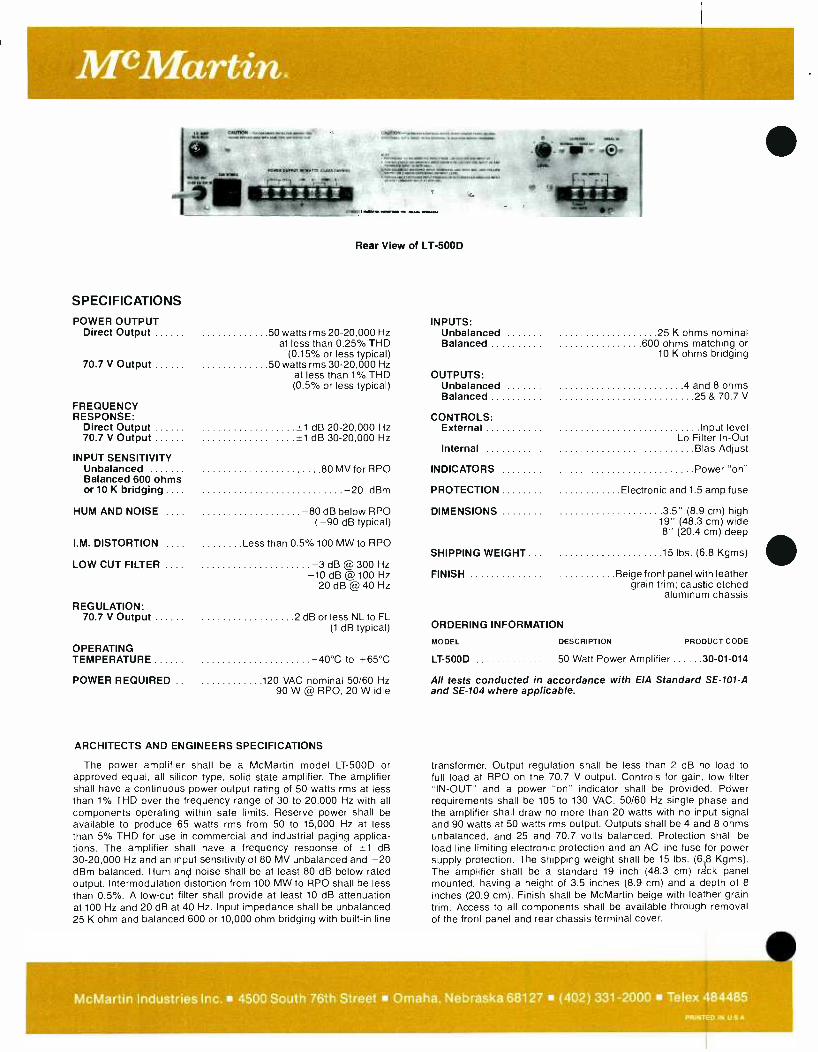
McMartin.
Rear View of LT -500D
SPECIFICATIONS
POWER OUTPUT INPUTS: Direct Output 50 watts rms 20- 20,000 Hz Unbalanced 25 K ohms nominal
at less than 0.25% THD Balanced 600 ohms matching or (0.15% or less typical) 10 K ohms bridging
70.7 V Output 50 watts rms 30- 20,000 Hz at less than 1% THD OUTPUTS: (0.5% or less typical) Unbalanced 4 and 8 ohms
Balanced 25 & 70.7 V FREQUENCY RESPONSE: CONTROLS:
Direct Output --1 dB 20- 20,000 Hz External Input level 70.7 V Output *1 dB 30- 20,000 Hz Lo Filter In -Out
Internal Bias Adjust INPUT SENSITIVITY
Unbalanced 80 MV for RPO INDICATORS Power "on" Balanced 600 ohms or 10 K bridging .... -20 dBm PROTECTION Electronic and 1.5 amp fuse
HUM AND NOISE -80 dB below RPO DIMENSIONS 3.5" (8.9 cm) high ( -90 dB typical) 19" (48.3 cm) wide
8" (20.4 cm) deep I.M. DISTORTION .... Less than 0.5% 100 MW to RPO
SHIPPING WEIGHT .. . 15 lbs. (6.8 Kgms) LOW CUT FILTER .... -3 dB @ 300 Hz
-10 dB @100 Hz -20 dB @ 40 Hz
FINISH Beige front panel with leather grain trim; caustic etched
aluminum chassis REGULATION:
70.7 V Output 2 dB or less NL to FL (1 dB typical) ORDERING INFORMATION
MODEL DESCRIPTION PRODUCT CODE OPERATING TEMPERATURE -40 °C to +65 °C LT-500D 50 Watt Power Amplifier 30 -01 -014
POWER REQUIRED .. 120 VAC nominal 50/60 Hz 90 W @ RPO, 20 W idle
All tests conducted in accordance with EIA Standard SE -101 -A and SE -104 where applicable.
ARCHITECTS AND ENGINEERS SPECIFICATIONS
The power amplifier shall be a McMartin model LT -500D or approved equal, all silicon type, solid state amplifier. The amplifier shall have a continuous power output rating of 50 watts rms at less than 1% THD over the frequency range of 30 to 20,000 Hz with all components operating within safe limits. Reserve power shall be available to produce 65 watts rms from 50 to 15,000 Hz at less than 5% THD for use in commercial and industrial paging applica- tions. The amplifier shall have a frequency response of ±1 dB 30- 20,000 Hz and an input sensitivity of 80 MV unbalanced and -20 dBm balanced. Hum and noise shall be at least 80 dB below rated output. Intermodulation distortion from 100 MW to RPO shall be less than 0.5 %. A low -cut filter shall provide at least 10 dB attenuation at 100 Hz and 20 dB at 40 Hz. Input impedance shall be unbalanced 25 K ohm and balanced 600 or 10,000 ohm bridging with built -in line
transformer. Output regulation shall be less than 2 dB no load to full load at RPO on the 70.7 V output. Controls for gain, low filter "IN -OUT" and a power "on" indicator shall be provided. Power requirements shall be 105 to 130 VAC, 50/60 Hz single phase and the amplifier shall draw no more than 20 watts with no input signal and 90 watts at 50 watts rms output. Outputs shall be 4 and 8 ohms unbalanced, and 25 and 70.7 volts balanced. Protection shall be load line limiting electronic protection and an AC line fuse for power supply protection. The shipping weight shall be 15 lbs. (6.8 Kgms). The amplifier shall be a standard 19 inch (48.3 cm) rack panel mounted, having a height of 3.5 inches (8.9 cm) and a depth of 8
inches (20.9 cm). Finish shall be McMartin beige with leather grain trim. Access to all components shall be available through removal of the front panel and rear chassis terminal cover.
McMartin Industries Inc. 4500 South 76th Street Omaha, Nebraska 68127 (402) 331 -2000 Telex 484485 PRINTED IN LI S A
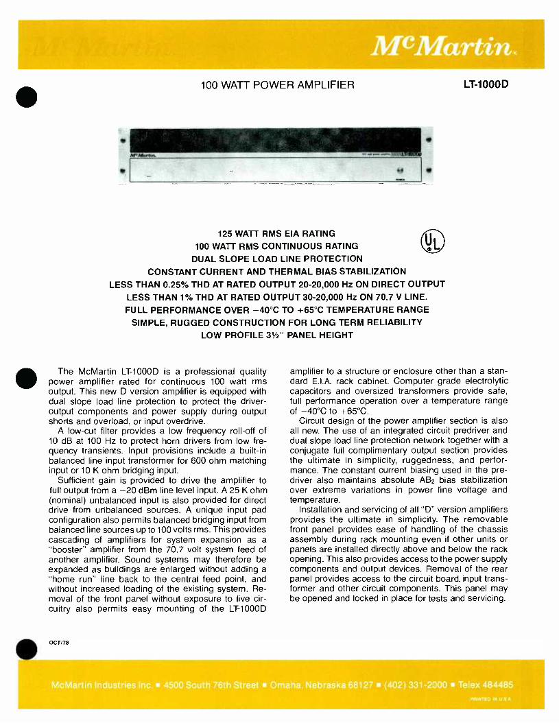
100 WATT POWER AMPLIFIER LT1000D
125 WATT RMS EIA RATING
100 WATT RMS CONTINUOUS RATING
DUAL SLOPE LOAD LINE PROTECTION
CONSTANT CURRENT AND THERMAL BIAS STABILIZATION
LESS THAN 0.25% THD AT RATED OUTPUT 20- 20,000 Hz ON DIRECT OUTPUT
LESS THAN 1% THD AT RATED OUTPUT 30- 20,000 Hz ON 70.7 V LINE.
FULL PERFORMANCE OVER -40 °C TO +65 °C TEMPERATURE RANGE
SIMPLE, RUGGED CONSTRUCTION FOR LONG TERM RELIABILITY LOW PROFILE 31/2" PANEL HEIGHT
The McMartin LT -1000D is a professional quality power amplifier rated for continuous 100 watt rms output. This new D version amplifier is equipped with dual slope load line protection to protect the driver - output components and power supply during output shorts and overload, or input overdrive.
A low -cut filter provides a low frequency roll -off of 10 dB at 100 Hz to protect horn drivers from low fre- quency transients. Input provisions include a built -in balanced line input transformer for 600 ohm matching input or 10 K ohm bridging input.
Sufficient gain is provided to drive the amplifier to full output from a -20 dBm line level input. A 25 K ohm (nominal) unbalanced input is also provided for direct drive from unbalanced sources. A unique input pad configuration also permits balanced bridging input from balanced line sources up to 100 volts rms. This provides cascading of amplifiers for system expansion as a "booster" amplifier from the 70.7 volt system feed of another amplifier. Sound systems may therefore be expanded as buildings are enlarged without adding a "home run" line back to the central feed point, and without increased loading of the existing system. Re- moval of the front panel without exposure to live cir- cuitry also permits easy mounting of the LT -1000D
OCT/78
amplifier to a structure or enclosure other than a stan- dard E.I.A. rack cabinet. Computer grade electrolytic capacitors and oversized transformers provide safe, full performance operation over a temperature range of -40 °C to +65 °C.
Circuit design of the power amplifier section is also all new. The use of an integrated circuit predriver and dual slope load line protection network together with a
conjugate full complimentary output section provides the ultimate in simplicity, ruggedness, and perfor- mance. The constant current biasing used in the pre - driver also maintains absolute AB2 bias stabilization over extreme variations in power line voltage and temperature.
Installation and servicing of all "D" version amplifiers provides the ultimate in simplicity. The removable front panel provides ease of handling of the chassis assembly during rack mounting even if other units or panels are installed directly above and below the rack opening. This also provides access to the power supply components and output devices. Removal of the rear panel provides access to the circuit board, input trans- former and other circuit components. This panel may be opened and locked in place for tests and servicing.
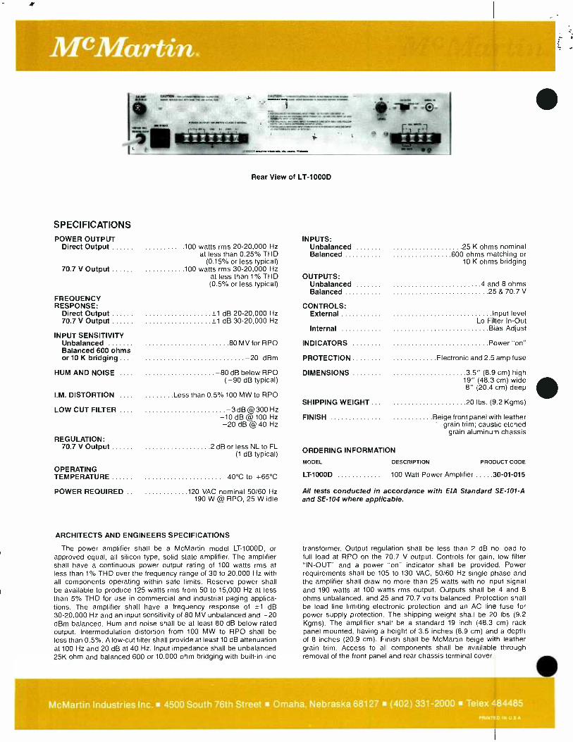
Mc Martin.
Rear View of LT -1000D
SPECIFICATIONS
POWER OUTPUT INPUTS: Direct Output 100 watts rms 20- 20,000 Hz Unbalanced 25 K ohms nominal
at less than 0.25% THD Balanced 600 ohms matching or (0.15% or less typical) 10 K ohms bridging
70.7 V Output 100 watts rms 30- 20,000 Hz at less than 1% THD OUTPUTS: (0.5% or less typical) Unbalanced 4 and 8 ohms
Balanced 25 & 70.7 V FREQUENCY RESPONSE: CONTROLS:
Direct Output +1 dB 20- 20,000 Hz External Input level 70.7 V Output +1 dB 30- 20,000 Hz Lo Filter In -Out
Internal Bias Adjust INPUT SENSITIVITY
Unbalanced 80 MV for RPO INDICATORS Power "on" Balanced 600 ohms or 10 K bridging .... -20 dBm PROTECTION Electronic and 2.5 amp fuse
HUM AND NOISE .... -80 dB below RPO DIMENSIONS 3.5" (8.9 cm) high ( -90 dB typical) 19" (48.3 cm) wide
8" (20.4 cm) deep I.M. DISTORTION .... Less than 0.5% 100 MW to RPO
SHIPPING WEIGHT .. . 20 lbs. (9.2 Kgms) LOW CUT FILTER .... -3 dB @300 Hz
-10 dB @100 Hz FINISH Beige front panel with leather -20 dB @ 40 Hz ' grain trim; caustic etched
grain aluminum chassis REGULATION:
70.7 V Output 2 dB or less NL to FL (1 dB typical) ORDERING INFORMATION
MODEL DESCRIPTION PRODUCT CODE
OPERATING TEMPERATURE -40 °C to +65 °C LT-1000D 100 Watt Power Amplifier 30 -01 -015
POWER REQUIRED .. 120 VAC nominal 50/60 Hz 190 W @ RPO, 25 W idle
All tests conducted in accordance with EIA Standard SE -101 -A and SE -104 where applicable.
ARCHITECTS AND ENGINEERS SPECIFICATIONS
The power amplifier shall be a McMartin model LT- 1000D, or approved equal, all silicon type, solid state amplifier. The amplifier shall have a continuous power output rating of 100 watts rms at less than 1% THD over the frequency range of 30 to 20,000 Hz with all components operating within safe limits. Reserve power shall be available to produce 125 watts rms from 50 to 15,000 Hz at less than 5% THD for use in commercial and industrial paging applica- tions. The amplifier shall have a frequency response of ±1 dB 30- 20,000 Hz and an input sensitivity of 80 MV unbalanced and -20 dBm balanced. Hum and noise shall be at least 80 dB below rated output. Intermodulation distortion from 100 MW to RPO shall be less than 0.5 %. A low -cut filter shall provide at least 10 dB attenuation at 100 Hz and 20 dB at 40 Hz. Input impedance shall be unbalanced 25K ohm and balanced 600 or 10,000 ohm bridging with built -in line
transformer. Output regulation shall be less than 2 dB no load to full load at RPO on the 70.7 V output. Controls for gain, low filter "IN -OUT" and a power "on" indicator shall be provided. Power requirements shall be 105 to 130 VAC, 50/60 Hz single phase and the amplifier shall draw no more than 25 watts with no input signal and 190 watts at 100 watts rms output. Outputs shall be 4 and 8 ohms unbalanced, and 25 and 70.7 volts balanced. Protection shall be load line limiting electronic protection and an AC line fuse for power supply protection. The shipping weight shall be 20 lbs (9.2 Kgms). The amplifier shall be a standard 19 inch (48.3 cm) rack panel mounted, having a height of 3.5 inches (8.9 cm) and a depth of 8 inches (20.9 cm). Finish shall be McMartin beige with leather grain trim. Access to all components shall be available through removal of the front panel and rear chassis terminal cover.
McMartin Industries Inc. 4500 South 76th Street Omaha, Nebraska 68127 (402) 331 -2000 Telex 484485 PRINTED IN U S A
200 WATT POWER AMPLIFIER
WMartfn. u
250 WATT rms E.I.A. RATING
200 WATT rms CONTINUOUS RATING
FAILSAFE ELECTRONIC PROTECTION
CONSTANT CURRENT AND THERMAL BIAS STABILIZATION
LESS THAN 1% THD AT RATED OUTPUT 50- 10,000 Hz ON 70.7 V LINE
FULL PERFORMANCE OVER -40 °C TO +65 °C TEMPERATURE RANGE
MODULAR CONSTRUCTION WITH REMOVABLE REAR CIRCUIT ASSEMBLY
The McMartin LT -2000D is a professional quality power amplifier rated for continuous 200 watt rms output. The "D" version amplifiers are all equipped with a new im- proved instantaneous shutdown, automatic reset, all electronic M -Gard protection network. This circuit pre- vents damage to the driver -output components and power supply during output shorts and overload or input overdrive.
A low -cut filter provides a low frequency roll -off of 10 dB at 100 Hz to protect horn drivers from low frequency transients. Input provisions include a built -in balanced line input transformer for 600 ohm matching input or 10K ohm bridging. Sufficient gain is provided to drive the amplifier to full output from a -20 dBm line level input. A 25K ohm (nominal) unbalanced input is also provided for direct drive from unbalanced sources. A unique input pad configuration also permits balanced bridging input from balanced line sources up to 100 volts rms. This provides cascading of amplifiers for system expansion as a "booster" amplifier from the 70.7 volt system feed of another amplifier. Sound sys- tems may therefore be expanded as buildings are
JUNE 79
LT-2000D
enlarged without adding a "home run" line back to the central feed point, and without increased loading of the existing system. Computer grade electrolytic capaci- tors and oversized transformers provide safe, full per- formance operation over a temperature range of -40 °C to +65 °C.
Installation and servicing of all "D" version amplifiers provides the ultimate in simplicity. The removable front panel provides ease of handling of the heavy chassis assembly during rack mounting, even if other units or panels are installed directly above and below the rack opening. This also provides access to the power supply components for servicing. The entire amplifier circuit assembly is mounted on the removable rear panel. The rear panel contains the driver and protection circuit board input- output terminations, and the output stage heatsinks and devices. This panel may either be opened and locked in place for tests and field servicing, or it may be completely unplugged and removed for bench servicing without removing the heavy power supply assembly from the rack installation.
McMartin Industries Inc. 4500 South 76th Street Omaha. Nebraska 68127 (402) 331 -2000 Telex 484485 PRINTED IN U S A

McMartin, SPECIFICATIONS
POWER OUTPUT: Continuous rms @ less than 1% THD:
Direct Output .... 200 watts 50- 15,000 Hz
70.7 Volt Output 200 watts 50- 10,000 Hz
E.I.A. Rating less than 5% THD 250 watts
50- 10,000 Hz
FREQUENCY RESPONSE:
Direct Output *1 dB, 30- 20,000 Hz
70.7 Volt Output ... *1 dB, 30- 15,000 Hz
INPUT SENSITIVITY: Unbalanced 80 MV for Rated Power Output
Balanced 600 ohms or 10K bridging -20 dBm
HUM & NOISE -80 dB below RPO
I.M. DISTORTION .. Less than 0.5% 100 MV to RPO
LOW CUT FILTER -3dB @300 Hz -10 dB @ 100 Hz -20 dB @ 40 Hz
REGULATION 70 V OUTPUT 2 dB or less
OPERATING TEMPERATURE -40 °C to +65 °C
ARCHITECTS AND ENGINEERS SPECIFICATIONS
The power amplifier shall be a McMartin model LT- 2000D, or ap- proved equal, all silicon type, solid state amplifier. The amplifier shall have a continuous power output rating of 200 watts rms at less than 1% THD over the frequency range of 50 to 10,000 Hz with all compo- nents operating within safe limits. Reserve power shall be available to produce 250 watts rms from 50 to 10,000 Hz at less than 5% THD for use in commercial and industrial paging applications requiring only intermittent duty operation. The amplifier shall have a frequency response of 30 to 15,000 Hertz ±1 dB and an input sensitivity of 80 MV unbalanced and -20 dBm balanced. Hum and noise shall be at least 80 dB below rated output. Intermodulation distortion from 100
MW to RPO shall be less than 0.5 %. A low -cut input filter shall provide at least 10 dB attenuation at 100 Hz and 20 dB at 40 Hz.
Input impedance shall be unbalanced 25K ohm and balanced
POWER REQUIRED
INPUTS: Unbalanced
Balanced
OUTPUTS: Unbalanced
120 VAC nominal, 50/60 Hz 500 watts @ RPO
45 W idle
25K ohms
600 ohm matching 10K ohm bridging
1.5 and 8 ohms
Balanced .. 25 and 70.7 V
CONTROLS: External Input level
Lo filter "IN -OUT"
Internal Input gain limit Current trip level
INDICATORS Power on
PROTECTION Electronic and 6.2 amp fuse
DIMENSIONS 7'(17.8 cm) High 19 "(48.3 cm) wide
11 "(27.9 cm) depth
WEIGHT actual 57.0 lbs (25.8 kg) shipping 60.0 lbs (27.2 kg)
FINISH: Beige front panel with leather grain trim; Caustic -etched aluminum chassis
ORDERING INFORMATION: Model Description Product Code
LT -2000D ...200 Watt Power Amplifier 30 -01 -016
All tests conducted in accordance with E.I.A. Standard SE -101 -A
and SE -104 where applicable.
600 or 10,000 ohm bridging with built -in line transformer. Regula- tion shall be better than 2 dB. Controls for gain, filter "IN -OUT" and a
power "ON" indicator shall be provided. Power requirements shall be 105 to 130 VAC, 50/60 Hz single phase and the amplifier shall draw no more than 45 watts with no input signal and 500 watts at 200 watts rms output. Outputs shall be 1.5 and 8 ohms unbalanced and 25 and 70.7 V volts balanced. Protection shall be self- resetting electronic shutdown and an AC line fuse for power supply protection. The ship- ping weight shall be 60 pounds (27 Kgms). The amplifier shall be a
standard 19 inch (48.3 cm) rack panel mounted, having a height of 7
inches (17.8 cm) and a depth of 11 inches (48.3 cm). Finish shall be McMartin beige with leather grain trim. Access to all components shall be available through removal of the front panel and rear chassis assembly.
McMartin Industries Inc. 4500 South 76th Street Omaha. Nebraska 68127 (402) 331 -2000 Telex 484485 PRINTED IN U S A
McMartin. 350 WATT POWER AMPLIFIER
425 WATT rms E.I.A. RATING
350 WATT rms CONTINUOUS RATING
FAILSALE ELECTRONIC PROTECTION
CONSTANT CURRENT AND THERMAL BIAS STABILIZATION
LESS THAN 1% THD AT RATED OUTPUT 50- 10,000 Hz ON 70.7 V LINE
FULL PERFORMANCE OVER -40 °C TO +65 °C TEMPERATURE RANGE
MODULAR CONSTRUCTION WITH REMOVABLE REAR CIRCUIT ASSEMBLY
The McMartin LT -3500D is a professional quality power amplifier rated for continuous 350 watt rms output. The "D" version amplifiers are all equipped with a new im- proved instantaneous shutdown, automatic reset, all electronic M -Gard protection network. This circuit pre- vents damage to the driver -output components and power supply during output shorts and overload or input overdrive.
A low -cut filter provides a low frequency roll -off of 10 dB at 100 Hz to protect horn drivers from low frequency transients. Input provisions include a built -in balanced line input transformer for 600 ohm matching input or 10K ohm bridging. Sufficient gain is provided to drive the amplifier to full output from a -20 dBm line level input. A 25K ohm (nominal) unbalanced input is also provided for direct drive from unbalanced sources. A unique input pad configuration also permits balanced bridging input from balanced line sources up to 100 volts rms. This provides cascading of amplifiers for system expansion as a "booster" amplifier from the 70.7 volt system feed of another amplifier. Sound sys- tems may therefore be expanded as buildings are JUNE /79
LT-3500D
enlarged without adding a "home run" line back to the central feed point, and without increased loading of the existing system. Computer grade electrolytic capaci- tors and oversized transformers provide safe, full per- formance operation over a temperature range of -40 °C to +65 °C.
Installation and servicing of all "D" version amplifiers provides the ultimate in simplicity. The removable front panel provides ease of handling of the heavy chassis assembly during rack mounting, even if other units or panels are installed directly above and below the rack opening. This also provides access to the power supply components for servicing. The entire amplifier circuit assembly is mounted on the removable rear panel. The rear panel contains the driver and protection circuit board, input- output terminations, and the output stage heatsinks and devices. This panel may either be opened and locked in place for tests and field servicing, or it may be completely unplugged and removed for bench servicing without removing the heavy power supply assembly from the rack installation.
McMartin Industries Inc. 4500 South 76th Street Omaha. Nebraska 68127 (402) 331 -2000 Telex 484485 PRINTED IN U S A
SPECIFICATIONS
POWER OUTPUT: Continuous rms @ less than 1% THD:
Direct Output
70.7 Volt Output
E.I.A. Rating less than 5% THD
FREQUENCY RESPONSE:
Direct Output
70.7 Volt Output
INPUT SENSITIVITY:
Unbalanced
Balanced 600 ohms or 10K bridging
HUM & NOISE
I.M. DISTORTION
LOW CUT FILTER
REGULATION 70 V OUTPUT
OPERATING TEMPERATURE
350 watts 50- 15,000 Hz
350 watts 50- 10,000 Hz
425 watts 50- 10,000 Hz
±1 dB, 30- 20,000 Hz
*1 dB, 30- 15,000 Hz
80 MV for Rated Power Output
-20 dBm
-80 dB below RPO
Less than 0.5% 100 MV to RPO
-3 dB @ 300 Hz -10 dB @ 100 Hz -20 dB @ 40 Hz
2 dB or less
-40 °C to +65 °C
POWER REQUIRED 120 VAC, nominal 50/60 Hz 800 watts @ RPO 45 W idle
INPUTS: Unbalanced 25K ohms
Balanced 600 ohm matching 10K ohm bridging
OUTPUTS: Unbalanced 15 ohms Balanced 70.7V
CONTROLS: External Input level
Low filter "IN -OUT" Internal Input gain limit
Current trip level
INDICATORS Power on
PROTECTION Electronic and 10 amp fuse
DIMENSIONS height 7" (17.8 cm) width 19" (48.3 cm) depth 11" (27.9 cm)
WEIGHT actual 65.0 lbs (29.4 kg) shipping 70.0 lbs (32.0 kg)
FINISH Beige front panel with leather grain trim; Caustic -etched aluminum chassis
ORDERING INFORMATION:
Model Description Product Code
LT-3500D 350 watt power amplifier 30 -01 -017
ARCHITECTS AND ENGINEERS SPECIFICATIONS
The power amplifier shall be a McMartin model LT- 3500D, or ap- proved equal, all silicon type solid state amplifier. The amplifier shall have a continuous power output rating of 350 watts rms at less than 1% THD over the frequency range of 50 to 10,000 Hz with all compo- nents operating within safe limits. Reserve power shall be available to produce 425 watts rms from 50 to 10,000 Hz at less than 5% THD for use in commercial and industrial paging applications requiring only intermittant duty operation. The amplifier shall have a frequency response of 30 to 15,000 Hertz ±1 dB and input sensitivity of 80 MV unbalanced and -20 dBm balanced. Hum and noise shall be at least 80 dB below rated output. Intermodulation distortion from 100 MW to RPO shall be less than 0.5 %. A low -cut input filter shall provide at least 10 dB attenuation at 100 Hz and 20 dB at 40 Hz. Input impedance shall be unbalanced 25K ohm and balanced 600 or
All tests conducted in accordance with E.I.A. Standard SE -101 -A and SE -104 where applicable.
10,000 ohm bridging with built -in line transformer. Regulation shall be better than 2 dB. Controls for gain, filter "IN -OUT" and a power "ON" indicator shall be provided. Power requirements shall be 105 to 130 VAC, 50/60 Hz single phase and the amplifier shall draw no more than 45 watts with no input signal and 800 watts at 350 watts rms output. Outputs shall be 1.5 ohms unbalanced and 70.7 volts bal- anced. Protection shall be self resetting electronic shutdown and an AC line fuse for power supply protection. The shipping weight shall be 70 pounds (32 Kgms). The amplifier shall be standard 19 inch (48.3 cm) rack panel mounted, having a height of 7 inches (17.8 cm), and a depth of 11 inches (27.9 cm). Finish shall be McMartin beige with leather grain trim. Access to all components shall be available through removal of the front panel and rear chassis assembly.
McMartin Industries Inc. 4500 South 76th Street Omaha, Nebraska 68127 (402) 331 -2000 Telex 484485.
PRIN7ED IN U S A
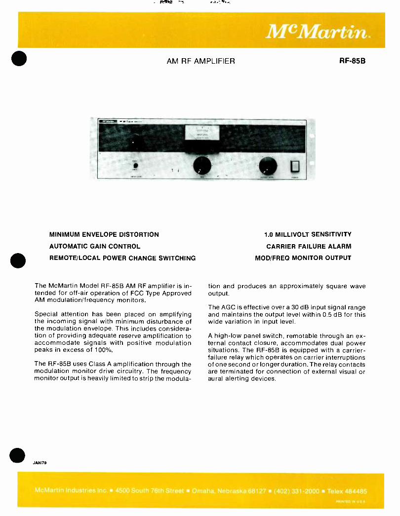
AM RF AMPLIFIER
MINIMUM ENVELOPE DISTORTION
AUTOMATIC GAIN CONTROL
REMOTE/LOCAL POWER CHANGE SWITCHING
The McMartin Model RF -85B AM RF amplifier is in- tended for off -air operation of FCC Type Approved AM modulation /frequency monitors.
Special attention has been placed on amplifying the incoming signal with minimum disturbance of the modulation envelope. This includes considera- tion of providing adequate reserve amplification to accommodate signals with positive modulation peaks in excess of 100 %.
The RF -85B uses Class A amplification through the modulation monitor drive circuitry. The frequency monitor output is heavily limited to strip the modula-
JAN/79
R F-85 B
1.0 MILLIVOLT SENSITIVITY
CARRIER FAILURE ALARM
MOD /FRED MONITOR OUTPUT
tion and produces an approximately square wave output.
The AGC is effective over a 30 dB input signal range and maintains the output level within 0.5 dB for this wide variation in input level.
A high -low panel switch, remotable through an ex- ternal contact closure, accommodates dual power situations. The RF -85B is equipped with a carrier - failure relay which operates on carrier interruptions of one second or longer duration. The relay contacts are terminated for connection of external visual or aural alerting devices.
McMartin Industries Inc. 4500 South 76th Street Omaha, Nebraska 68127 (402) 331 -2000 Telex 484485 PRINTED IN U S A
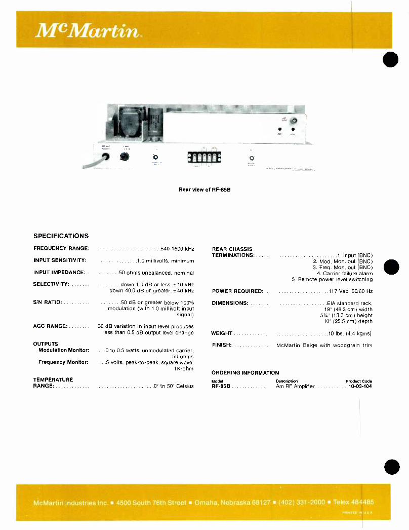
McMartin.
Rear view of RF -85B
SPECIFICATIONS
FREQUENCY RANGE: 540 -1600 kHz REAR CHASSIS TERMINATIONS 1 Input (BNC)
INPUT SENSITIVITY: 1 0 millivolts, minimum 2. Mod. Mon. out (BNC) 3. Freq. Mon. out (BNC)
INPUT IMPEDANCE: 50 ohms unbalanced, nominal 4. Carrier failure alarm
SELECTIVITY: down 1.0 dB or less, ±10 kHz 5. Remote power level switching
down 40.0 dB or greater, ±40 kHz POWER REQUIRED: . 117 Vac, 50/60 Hz
S/N RATIO: 50 dB or greater below 100% modulation (with 1.0 millivolt input
signal)
DIMENSIONS: EIA standard rack, 19" (48.3 cm) width
51/4" (13.3 cm) height 10" (25.5 cm) depth
AGC RANGE 30 dB variation in input level produces less than 0.5 dB output level change WEIGHT 10 lbs. (4.4 kgms)
OUTPUTS FINISH: McMartin Beige with woodgrain trim Modulation Monitor: ...0 to 0.5 watts, unmodulated carrier,
50 ohms Frequency Monitor: ...5 volts, peak -to -peak, square wave,
1K-ohm ORDERING INFORMATION
TEMPERATURE Model Description Product Code RANGE 0° to 50° Celsius RF -85B Am RF Amplifier 10 -03 -104
McMartin Industries Inc. 4500 South 76th Street Omaha, Nebraska 68127 (402) 331 -2000 Telex 484485
PRINTED IN U S A
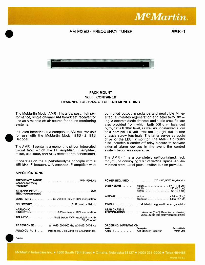
AM FIXED - FREQUENCY TUNER
RACK MOUNT
SELF - CONTAINED DESIGNED FOR E.B.S. OR OFF -AIR MONITORING
The McMartin Model AMR - 1 is a low cost, high per- formance, single channel AM broadcast receiver for use as a reliable off -air source for house monitoring systems.
It is also intended as a companion AM receiver unit for use with the McMartin Model EBS - 2 EBS Decoder.
The AMR - 1 contains a monolithic silicon integrated circuit from which the RF amplifier, IF amplifier, mixer, oscillator, and AGC detector are constructed.
It operates on the superheterodyne principle with a 455 kHz IF frequency. A cascode IF amplifier with
AMR -1
controlled output impedance and negligible Miller - effect eliminates regeneration and selectivity skew- ing. A discrete diode detector and audio amplifier are also provided from which both 600 ohm balanced output at a 0 dBm level, as well as unbalanced audio at a nominal 1.0 volt level are brought out to rear chassis screw terminals. The latter serves as audio drive for the EBS - 2 monitor. The AMR - 1 circuitry also includes a carrier off relay closure to activate external alarm devices in the event the control system becomes inoperative.
The AMR - 1 is a completely self- contained, rack mount unit occupying 13/4" of vertical space. An illu- minated front panel power switch is also provided.
SPECIFICATIONS
FREQUENCY RANGE .
(specify operating frequency)
540 -1620 kHz POWER REQUIRED ..
DIMENSIONS
120 VAC, 50/60 Hz, 6 watts
height 13/4" (4.45 cm) width 19 "(48.3 cm)
ANTENNA INPUT ... . 75 depth 6 "(12.7 cm) (BNC type connector)
WEIGHT actual 4 5 lbs. (2 kg) SENSITIVITY 30µV /20 dB S/N at 30% modulation shipping 6 lbs. (2.7 kg)
SELECTIVITY 6 dB point: ± 10 kHz FINISH .. McMartin beighe with woodgrain trim
HARMONIC REAR CHASSIS DISTORTION 3.0% or less at 90% modulation TERMINATIONS ... Antenna (BNC); Balanced audio out;
unbal. audio out; Relay contacts (n.o.) S/N RATIO 45 dB below 100% modulation with
10µV input
AF RESPONSE ± 1.0 dB, 50 -5,000 Hz; ± 3.0 dB, 5 -10 kHz ORDERING INFORMATION Model Description Product Code
AUDIO OUTPUTS OdBm,6000bal.,and 1.0 V,600Stunbal. AMR -1 AM Monitor Receiver 10- 04-003
OCT/80
McMartin Industries Inc. 4500 South 76th Street Omaha, Nebraska 68127 (402) 331 -2000 Telex 484485
PRINTED IN U S A

e
FIXED FREQUENCY FM TUNER
NEW PTD (PRECISE TRACKING DECODER)
IMPROVED SENSITIVITY
50 dB LINEAR AGC
The FMR -1D utilizes a new concept in tuner design providing space age technology in which the tuner actually tracks the modulated signal from the trans- mitter. The PTD will "lock on" and accurately recover the main channel signal identical to those originally transmitted. No multisection LC filters are used to disturb the original phase relationship of the trans- mitted signal reducing distortion. This system also tracks the original signal and reduces the effects of multipath propagation.
The selected 10.7 MHz signal is fed to IC -1 (MOB -605), a special integrated circuit where the signal is highly amplified and hard limited followed by a tracking decoder which converts the frequency modulated in- to the original composite signal with minimum inter - modulation distortion.
A specially designed mute circuit is incorporated in the integrated circuit to provide noise free muting
AUG/81
FMR-1D
BALANCED 600 OHM OUTPUT ( + 8 dBm)
ADJUSTABLE NOISE SQUELCH CONTROL
REAR PANEL RELAY CONTACTS (NO) OR (NC)
and is a function of RF noise rather than RF input level. A relay circuit will provide either contact closure or open contacts in the absence of the RF carrier. The relay threshold is also adjustable from 3 -15 microvolts.
An audio integrated circuit is used to drive a trans- former providing a balanced 600 ohm output at a level of + 18 dBm at 100% modulation at 400 Hz. A 15 kHz low pass filter eliminates the troublesome 19 kHz stereo pilot signal from the audio output when used for rebroadcast or recording.
The number of components have been greatly reduc- ed due to the use of an integrated circuit IF system. IC's are also used in the audio system; fewer corn - ponents means greater reliability.
The FMR -1 D utilizes only 13/4" of vertical rack space. An illuminated front panel power switch is provided.
McMartin Industries Inc. 4500 South 76th Street Omaha, Nebraska 68127 (402) 331 -2000 Telex 484485 PRINTED IN U S A
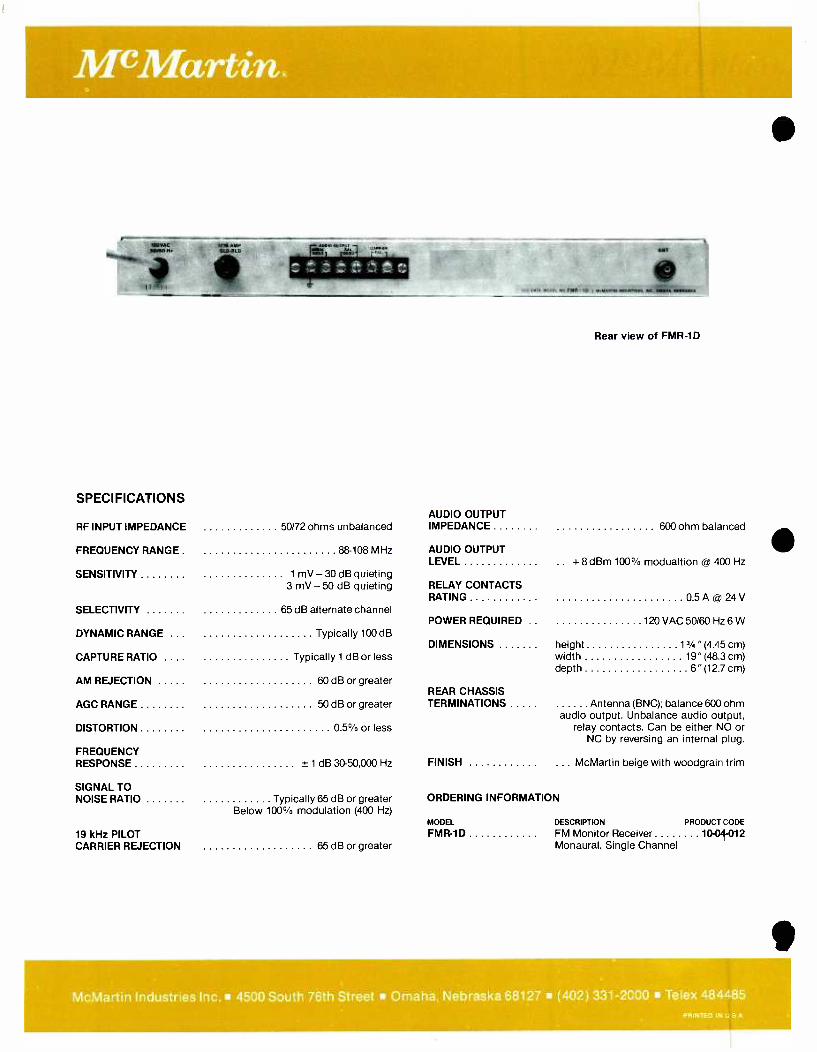
McMartin.
1110.K SOASAN, StO -Oto
it e 1714'
SPECIFICATIONS
DA, 00011 wa F MR- r, . re.ui r14. w.au. _
Rear view of FMR -1D
AUDIO OUTPUT RF INPUT IMPEDANCE 50/72 ohms unbalanced IMPEDANCE 600 ohm balanced
FREQUENCY RANGE . 88 -108 MHz AUDIO OUTPUT LEVEL .. +8 dBm 100% modualtion @ 400 Hz
SENSITIVITY 1 mV - 30 dB quieting 3 mV - 50 dB quieting RELAY CONTACTS
RATING 0 5 AO 24 V
SELECTIVITY 65 dB alternate channel POWER REQUIRED .. 120 VAC 50/60 Hz 6 W
DYNAMIC RANGE ... Typically 100 dB DIMENSIONS height 13/4 " (4.45 cm)
CAPTURE RATIO .... Typically 1 dB or less width 19" (48 3 cm) depth 6" (12.7 cm)
AM REJECTION 60 dB or greater REAR CHASSIS
AGC RANGE
DISTORTION
50 dB or greater
0 5% or less
TERMINATIONS Antenna (BNC); balance 600 ohm audio output. Unbalance audio output,
relay contacts. Can be either NO or NC by reversing an internal plug.
FREQUENCY RESPONSE ± 1 dB 30- 50,000 Hz FINISH ... McMartin beige with woodgrain trim
SIGNAL TO NOISE RATIO Typically 65 dB or greater ORDERING INFORMATION
Below 100% modulation (400 Hz) MODEL DESCRIPTION PRODUCT CODE
19 kHz PILOT FMR-1D FM Monitor Receiver 10 -04-012 CARRIER REJECTION 65 dB or greater Monaural, Single Channel
McMartin Industries Inc. 4500 South 76th Street Omaha, Nebraska 68127 (402) 331 -2000 Telex 484485
PRINTED IN U S A
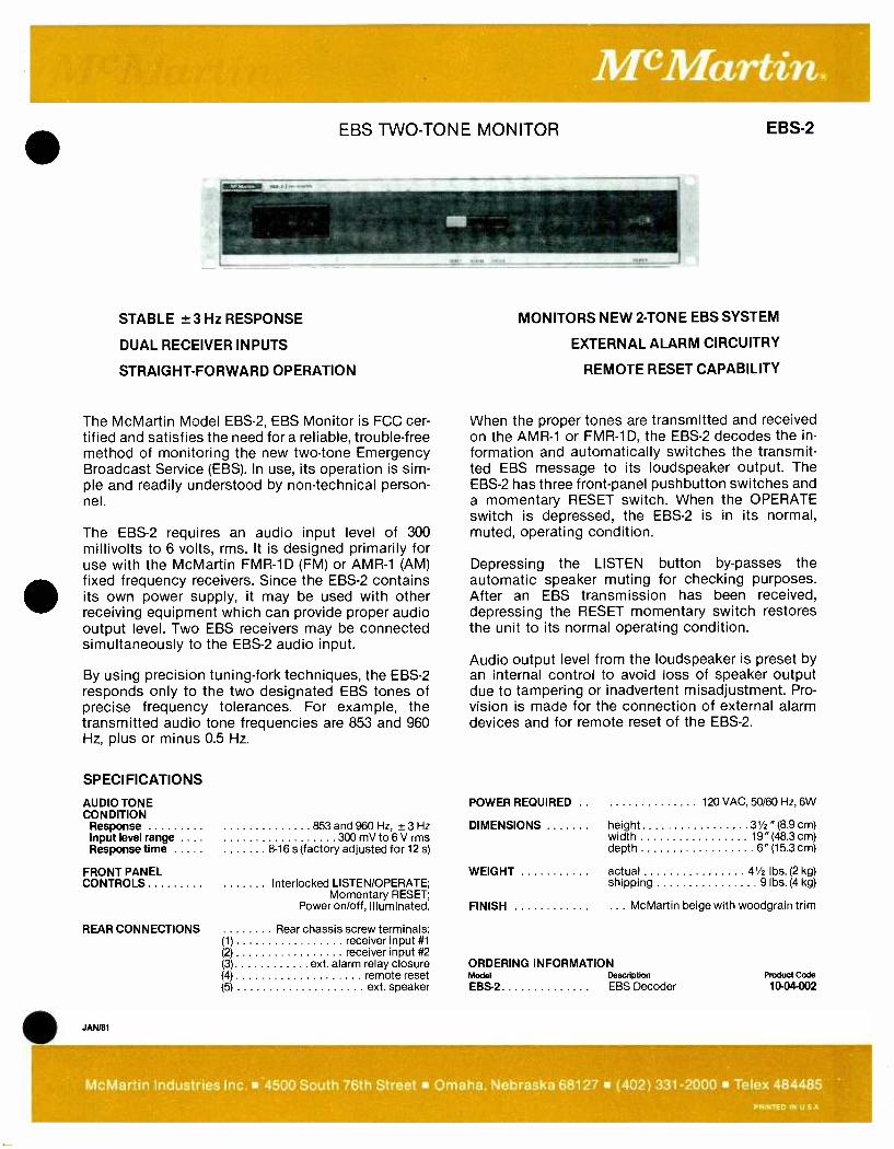
EBS TWO -TONE MONITOR EBS-2
131=111 ...
STABLE ± 3 Hz RESPONSE
DUAL RECEIVER INPUTS
STRAIGHT -FORWARD OPERATION
The McMartin Model EBS -2, EBS Monitor is FCC cer- tified and satisfies the need for a reliable, trouble -free method of monitoring the new two -tone Emergency Broadcast Service (EBS). In use, its operation is sim- ple and readily understood by non -technical person- nel.
The EBS -2 requires an audio input level of 300 millivolts to 6 volts, rms. It is designed primarily for use with the McMartin FMR -1D (FM) or AMR -1 (AM) fixed frequency receivers. Since the EBS -2 contains its own power supply, it may be used with other receiving equipment which can provide proper audio output level. Two EBS receivers may be connected simultaneously to the EBS -2 audio input.
By using precision tuning -fork techniques, the EBS -2 responds only to the two designated EBS tones of precise frequency tolerances. For example, the transmitted audio tone frequencies are 853 and 960 Hz, plus or minus 0.5 Hz.
SPECIFICATIONS
AUDIO TONE CONDITION
Response 853 and 960 Hz, ± 3 Hz Input level range .... 300 mV to 6 V rms Response time 8 -16 s (factory adjusted for 12 s)
FRONT PANEL CONTROLS Interlocked LISTEN /OPERATE;
Momentary RESET; Power on /off, illuminated.
REAR CONNECTIONS Rear chassis screw terminals:
JAN/81
(1) (2) (3) (4) (5)
receiver input #1 receiver input #2
ext. alarm relay closure remote reset ext. speaker
MONITORS NEW 2 -TONE EBS SYSTEM
EXTERNAL ALARM CIRCUITRY
REMOTE RESET CAPABILITY
When the proper tones are transmitted and received on the AMR -1 or FMR -1D, the EBS -2 decodes the in- formation and automatically switches the transmit- ted EBS message to its loudspeaker output. The EBS -2 has three front -panel pushbutton switches and a momentary RESET switch. When the OPERATE switch is depressed, the EBS -2 is in its normal, muted, operating condition.
Depressing the LISTEN button by- passes the automatic speaker muting for checking purposes. After an EBS transmission has been received, depressing the RESET momentary switch restores the unit to its normal operating condition.
Audio output level from the loudspeaker is preset by an internal control to avoid loss of speaker output due to tampering or inadvertent misadjustment. Pro- vision is made for the connection of external alarm devices and for remote reset of the EBS -2.
POWER REQUIRED .. 120 VAC, 50/60 Hz, 6W
DIMENSIONS height 31/2 " (8.9 cm) width 19" (48.3 cm) depth 6" (15.3 cm)
WEIGHT actual 41/2 lbs. (2 kg) shipping 9 lbs. (4 kg)
FINISH ... McMartin beige with woodgrain trim
ORDERING INFORMATION Model Description
EBS -2 EBS Decoder Product Code
10-04-002
McMartin Industries Inc. -4500 South 76th Street Omaha, Nebraska 68127 (402) 331 -2000 Telex 484485 PAINTED IN U S A

McMartin. PRECISION TWO -TONE EBS GENERATOR
MANUAL OR AUTO TIMING
INDEPENDENT TONE LEVEL CONTROLS
The McMartin Model TG -2 /EBS Precision Two Tone EBS Generator is FCC Type- Accepted to produce the Two -Tone Attention Signal for the new Emergency Broadcast System (EBS) effective for all AM, FM and TV stations on April 16, 1976.
The regulations specify the two tone frequencies as 853 and 960, ± 0.5 Hz. This stability is provided in the TG -2 /EBS by digital logic division from a highly - stable crystal oscillator. The derived audio tones are filtered and combined, with individual level controls to produce a minimum +8 dBm, balanced 600 ohm output for feeding the two -tone information through normal program channels.
The individual tone level controls permit presetting of the output level to meet the 40%, ±5% modulation
SPECIFICATIONS
OUTPUT FREQUENCIES 853 and 960 Hz
FREQUENCY STABILITY ± 0.2 Hz
OUTPUT LEVEL + 8 dBm min (each tone level independently adjustable)
OUTPUT IMPEDANCE 600 u, balanced
HUM & NOISE 65 dB below + 8 dBm outut
DISTORTION less than 1.5%
TIMED OUTPUT DURATION 22.5, ± 2.5 s
TG-2/EBS
CRYSTAL -DERIVED TONE BASE
REMOTE START
requirement of the new rules.
The TG -2 /EBS also incorporates an automatic dura- tion timing device. The two tones may be initiated either by manual operation of a front panel CON- TINUOUS OUTUT pushbutton, or may be preset by a TIMED OUTPUT pushbutton switch with automatic transmission of 22 seconds duration by operation of a momentary- action front panel START pushbutton. The latter operation may also be initiated remotely. A front panel LED indicator shows the presence of tones.
The TG -2 /EBS includes a self- contained power supp- ly and regulator. It is finished in beige with woodgrain trim.
DIMENSIONS height 3Yz "(8.9cm) width 19" (48.3 cm) depth 6" (15.3 cm)
WEIGHT actual 41/2 lbs. (2 kg) shipping 9 lbs. (4 kg)
FINISH ... McMartin beige with woodgrain trim
ORDERING INFORMATION Model Description
TG-2/EBS Precision two tone EBS Generator
Product Code
10 -04-011
McMartin Industries Inc. 4500 South 76th Street Omaha, Nebraska 68127 (402) 331 -2000 Telex 484485 PPINTED IN U S A

FM FREQUENCY /MODULATION MONITOR
r.., . I " ,..w
DIRECT READING AM & FM S/N
REAR ACCESS PLUG -IN CARDS
REMOTE METERING AVAILABLE
TBM-3700
INDEPENDENT FREQUENCY /MODULATION SECTIONS
BUILT -IN FREQUENCY MODULATION CALIBRATION
STEREO /SCA ADD -ON CAPABILITY
DESCRIPTION
The McMartin TBM -3700 combines the frequency deviation and modulation percentage functions in a single rack mount unit.
The TBM -3700 uses silicon solid -state semiconduc- tors. Most circuits are mounted on plug -in, glass epoxy base printed circuit boards accessible from the rear.
The frequency deviation and modulation monitoring functions are independent of each other. Frequency measurements and calibration switching may be per- formed without interruption of the modulation moni- toring or audio feed to house monitor systems. Audio output is automatically muted when RF feed to the TBM -3700 is not present.
MAY/78
The TBM -3700 incorporates circuitry permitting pre- cise calibration of the modulation percentage meter and measurement of inherent internal FM noise of the monitor (typically 75 dB below 100% modulation). Direct reading of AM and FM signal -to -noise ratios is also featured.
Provision is made for remote metering of both fre- quency deviation and modulation percentage. Ac- cessory kits for this purpose are available.
Two isolated composite signal outputs are provided for driving the McMartin TBM -2200 Stereo Modula- tion Monitor andjor TBM -2000A SCA Frequency/ Modulation Monitor.
The TBM -3700 conforms in all respects with FCC Rules (Approval #3 -190).
McMartin Industries Inc. 4500 South 76th Street Omaha, Nebraska 68127 (402) 331 -2000 Telex 484485 PRINTED IN U S A
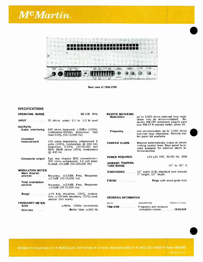
SPECIFICATIONS
OPERATING RANGE
111R 1111111
.313 110.0 33,7T7F3 'r-7131V5r 13 111311.
6 : °6 -a L L 1 C..131.,3
.W 3300 I ., ,.1k..,...,....._...,. e
Rear view of TBM -3700
88 -108 MHz
INPUT 50 ohms, unbal. 0.1 to 1.0 W. level
OUTPUTS: Audio monitoring
Distortion measurement
Composite output
MODULATION METER: Main channel position
Total modulation position
Range
FREQUENCY METER: Scale
Accuracy
600 ohms balanced; +2dBm (100% modulation- 400Hz) Distortion: less than 0.5% (50- 15,000 Hz)
10K ohms impedance, unbalanced; 5 volts (100% modulation @ 400 Hz) Distortion: 0.25% (30- 15,000 Hz) SNR: 66dB below 100% modulation @ 400 Hz
Two rear chassis BNC connectors - 300 ohms unbalanced; 1.0 volt peak - to -peak ±0.2dß (50- 100,000 Hz)
Accuracy, ±0.5dB; Freq. Response: ±0.5dB (30- 15,000 Hz)
Accuracy, ±0.5dB; Freq. Response: ±0.5dB (30- 75,000 Hz)
±75 kHz deviation, 100% modula- tion; ±100 kHz deviation, 133% mod- ulation (full scale)
±4kHz, 100Hz increments Better than ±500 Hz
REMOTE METERING: Modulation
Frequency
CARRIER ALARM
POWER REQUIRED.
AMBIENT TEMPERA- TURE RANGE
DIMENSIONS
up to 2,500 ohms external loop resis- tance may be accommodated. Re- quires RM -37T accessory plug -in card and RM -37 -R remote meter panel kit
can accommodate up to 3,000 ohms external loop resistance. Remote me- ter panel kit available
Monitor automatically mutes at preset muting control level. Rear panel term- inals available for external alarm in- terconnection
105 -125 VAC, 50/60 Hz, 45W
10° to 50° C
19" width (EIA) standard rack mount) 7" height, 13" depth
FINISH
ORDERING INFORMATION
MODEL
TBM-3700
Beige with wood grain trim
DESCRIPTION PRODUCT CODE
Frequency and monaural modulation monitor 10 -03 -049
McMartin Industries Inc 4500 South 76th Street Omaha. Nebraska 68127 (402) 331 -2000 Telex 484485 PRINTED IN U
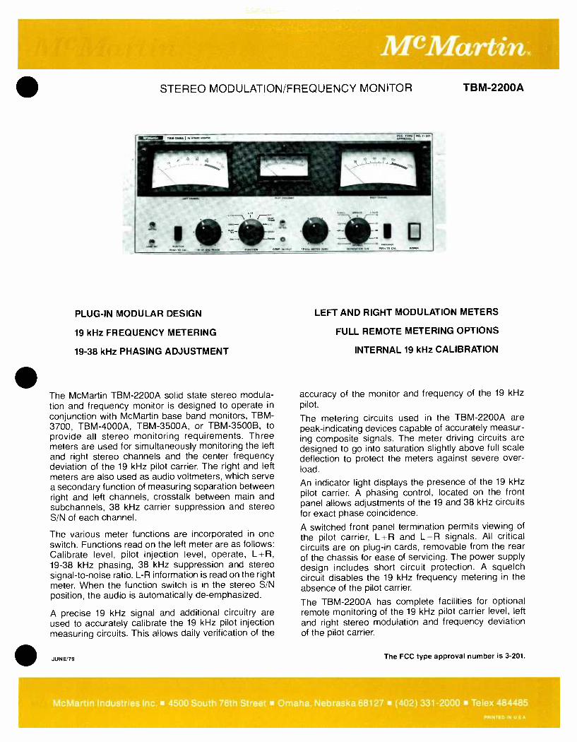
STEREO MODULATION /FREQUENCY MONITOR TBM -2200A
PLUG -IN MODULAR DESIGN
19 kHz FREQUENCY METERING
19 -38 kHz PHASING ADJUSTMENT
The McMartin TBM -2200A solid state stereo modula- tion and frequency monitor is designed to operate in
conjunction with McMartin base band monitors, TBM - 3700, TBM- 4000A, TBM- 3500A, or TBM- 3500B, to provide all stereo monitoring requirements. Three meters are used for simultaneously monitoring the left and right stereo channels and the center frequency deviation of the 19 kHz pilot carrier. The right and left meters are also used as audio voltmeters, which serve a secondary function of measuring separation between right and left channels, crosstalk between main and subchannels, 38 kHz carrier suppression and stereo S/N of each channel.
The various meter functions are incorporated in one switch. Functions read on the left meter are as follows: Calibrate level, pilot injection level, operate, L +R, 19 -38 kHz phasing, 38 kHz suppression and stereo signal -to -noise ratio. L -R information is read on the right meter. When the function switch is in the stereo S/N position, the audio is automatically de- emphasized.
A precise 19 kHz signal and additional circuitry are used to accurately calibrate the 19 kHz pilot injection measuring circuits. This allows daily verification of the
JUNE/79
LEFT AND RIGHT MODULATION METERS
FULL REMOTE METERING OPTIONS
INTERNAL 19 kHz CALIBRATION
accuracy of the monitor and frequency of the 19 kHz pilot.
The metering circuits used in the TBM -2200A are peak- indicating devices capable of accurately measur- ing composite signals. The meter driving circuits are designed to go into saturation slightly above full scale deflection to protect the meters against severe over- load.
An indicator light displays the presence of the 19 kHz pilot carrier. A phasing control, located on the front panel allows adjustments of the 19 and 38 kHz circuits for exact phase coincidence.
A switched front panel termination permits viewing of the pilot carrier, L +R and L -R signals. All critical circuits are on plug -in cards, removable from the rear of the chassis for ease of servicing. The power supply design includes short circuit protection. A squelch circuit disables the 19 kHz frequency metering in the absence of the pilot carrier.
The TBM -2200A has complete facilities for optional remote monitoring of the 19 kHz pilot carrier level, left and right stereo modulation and frequency deviation of the pilot carrier.
The FCC type approval number is 3 -201.
McMartin Industries Inc. 4500 South 76th Street Omaha, Nebraska 68127 (402) 331 -2000 Telex 484485 PRINTED IN U S A

McMartin.
111111
Rear view of TBM -2200A
SPECIFICATIONS COMPOSITE INPUT MEASUREMENT OF
Impedance- 5K ohms SUPPRESSED 38 kHz Sensitivity: 0 9 to 1.5 volts peak to peak CARRIER
Modulated 100% OUTPUTS with frequencies (left and right) above 5 kHz:
Audio output for No Modulation: ... monitoring circuits
Source impedance. 600 ohms balanced Level: +2 dBm at 100 percent modulation
at 400 Hz
Distortion- Less than 0.5 percent (50- 15,000 Hz)
Audio output for distortion measurement
Impedance- 10K ohms or greater Level: 5 volts at 100 percent at 400 Hz
Frequency response: *0 5 dB, 30- 15,000 Hz
DISTORTION Stereo: Stereo Noise Level:
0 35 percent, 30- 15,000 Hz
-66 dB below 100 percent modulation at 400 Hz
COMPOSITE OUTPUT Source Impedance: 1000 ohms Level: 0 3 volts rms Frequency Response: t0.2 dB, 50- 75,000 Hz
PILOT INJECTION CIRCUIT
Accuracy: *0.5 percent Meter Indication:... 6 -12 percent (pilot injection scale) Indicator Pilot lamp (operates at 5 percent of
greater injection level)
INTERNAL PILOT CALIBRATE
Accuracy:
MODULATION METERS (left or right)
Accuracy: Frequency Response:
SEPARATION Left and Right Channels: -45 dB or better (50 to 10,000 Hz)
-40 dB or better (10,000 -15,000 Hz)
NOTE: Separation can be measured internally down to 60 dB
-0 5 percent
-0 5 dB
0 5 dB, 30-15,000 Hz
CROSSTALK Main into stereo sub channel: Stereo subchannel into main channel: 67 kHz into main or stereo channel:...
PILOT CARRIER FREQUENCY METER
Deviation Range: .
Accuracy:
REMOTE MONITORING FACILITIES
Modulation:
Pilot Carrier Frequency:
POWER REQUIRED:
AMBIENT TEMPERATURE RANGE:
DIMENSIONS
WEIGHT
FINISH:
Better than 50 dB Better than 60 dB
50 dB or better
50 dB or better
66 dB or better
--2.5 Hz *0.25 Hz
Optional RM -22 T/R kit available. Left and right meter may be remotely moni- tored with 2500 ohm external loop re- sistance. Remote meters are completely
independent of internal meters.
Frequency deviation may be remotely monitored with 2500 ohms external loop
resistance.
105 -125 volts AC
10 -50 degrees C
width 19" (48.3 cm) height 7" (17.8 cm) depth 13" (33.0 cm)
actual 15 lbs (6.8 kg) shipping 19 lbs (8.6 kg)
McMartin beige with wood grain trim
ORDERING INFORMATION
Model TBM -2200A
RM-22T RM-22R
Description Product Code Stereo modulation and 10 -03 -034 pilot frequency monitor Remote metering plug -in card 10 -03 -037 Remote metering rack
mount panel 10 -03 -036
McMartin Industries Inc. 4500 South 76th Street Omaha, Nebraska 68127 (402) 331 -2000 Telex 484485 PRINZ ED IN U S A

SCA FREQUENCY /MODULATION MONITOR TBM -2000B
®
INTERNAL CALIBRATION
MODULAR PLUG -IN CARD DESIGN
DESCRIPTION
The McMartin TBM -2000B silicon solid -state SCA monitor, in conjunction with the McMartin TBM -3700, TBM- 3500B, TBM- 3500A, TBM -4000A or TBM -4500A monitors, will monitor all the characteristics of the SCA transmission. The TBM -2000B features the measurement of injec- tion level, modulation, frequency of the SCA carrier, SCA FM signal -to- noise, and crosstalk.
For simplicity of operation, the various metering functions are incorporated in one switch. The functions read on the right meter as follows: Set level -cal., injection level, ±6 kHz deviation, f4 kHz deviation, narrow band injection, and inter- nal signal -to -noise of the monitor. In addition, the TBM -2000B features push- button calibration of the frequency meter, injection level, and modu- lation meter.
The modulation meter is a peak indicating device capable of measuring true peak value. The meter is also used as an audio voltmeter to measure the FM signal -to -noise of the sub -channel, main to sub -channel crosstalk, crosstalk between two sub -channels and the inherent FM S/N of the monitor. When the meter range switch is in the 'operate' position, the meter ballistics conform to the FCC requirement.
Acrystal reference oscillator is used to calibrate the frequency meter. This oscillator and addi-
MARJ'74
REMOTE METERING OPTION
CARRIER -OFF MUTING
tional circuitry are used to accurately calibrate the modulation meter and the internal calibrate system. The internal FM noise of the TBM -2000B is typically 70 dB below 100% modulation.
The frequency meter is automatically protected against severe overload. A carrier light indicates presence of the sub -channel. The audio is auto- matically muted and the frequency meter de -acti- vated in the absence of the subcarrier. The mute threshold is adjustable.
The TBM -2000B has complete facilities for remote monitoring of the modulation, carrier fre- quency deviation, peak modulation indicator and sub -carrier presence indicator.
Two rear -chassis composite output terminations are available for viewing the wide band output.
A relay is activated when the SCA carrier is muted or falls below a predetermined level. One pair of relay closures are available on the rear chassis for operation of an external signal system for indication of carrier 'On' or 'Off' condition.
All critical circuits have double regulation for added stability. All solid state devices are oper- ated far below their rated voltage for greater reliability.
The FCC type approval number is 3 -200.
McMartin Industries Inc. 4500 South 76th Street Omaha, Nebraska 68127 (402) 331 -2000 Telex 48448
_PRNTED IN
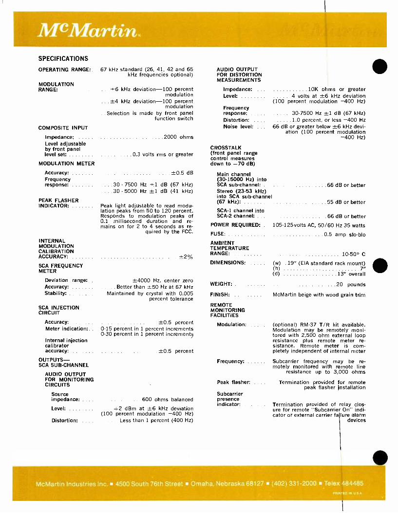
SPECIFICATIONS
OPERATING RANGE:
MODULATION RANGE:
COMPOSITE INPUT
Impedance: Level adjustable by front panel level set:
MODULATION METER
Accuracy: Frequency response:
PEAK FLASHER INDICATOR:
INTERNAL MODULATION CALI BRATION ACCURACY:
SCA FREQUENCY METER
Deviation range: Accuracy: Stability:
SCA INJECTION CIRCUIT
Accuracy: Meter indication:
Internal injection calibrator accuracy:
OUTPUTS - SCA SUB -CHANNEL
AUDIO OUTPUT FOR MONITORING CIRCUITS
Source impedance:
Level:
Distortion:
67 kHz standard (26, 41, 42 and 65 kHz frequencies optional)
+6 kHz deviation -100 percent modulation
+4 kHz deviation -100 percent modulation
Selection is made by front panel function switch
2000 ohms
0.3 volts rms or greater
+0.5 dB
30 - 7500 Hz ±1 dB (67 kHz) 30 - 5000 Hz ±1 dB (41 kHz)
Peak light adjustable to read modu- lation peaks from 50 to 120 percent. Responds to modulation peaks of 0.1 millisecond duration and re- mains on for 2 to 4 seconds as re-
quired by the FCC.
+2%
±4000 Hz, center zero Better than ±50 Hz at 67 kHz
Maintained by crystal with 0.005 percent tolerance
±0.5 percent 0 -15 percent in 1 percent increments 0 -30 percent in 1 percent increments
+0.5 percent
600 ohms balanced
+2 dBm at +6 kHz deviation (100 percent modulation -400 Hz)
Less than 1 percent (400 Hz)
AUDIO OUTPUT FOR DISTORTION MEASUREMENTS
Impedance: Level:
Frequency response: Distortion: Noise level:
CROSSTALK (front panel range control measures down to -70 dB)
10K ohms or greater 4 volts at ±6 kHz deviation
(100 percent modulation -400 Hz)
30 -7500 Hz ±1 dB (67 kHz) 1.0 percent, or less -400 Hz
66 dB or greater below +6 kHz devi- ation (100 percent modulation
-400 Hz)
Main channel (30 -15000 Hz) into SCA sub -channel: 66 dB or better Stereo (23 -53 kHz) into SCA sub -channel (67 kHz): 55 dB or better
SCA -1 channel into SCA -2 channel: 66 dB or better
POWER REQUIRED: 105 -125 volts AC, 50/60 Hz 35 watts
FUSE: 0 5 amp slo -blo
AMBIENT TEMPERATURE RANGE: 10 -50° C
DIMENSIONS: (w) 19" (EIA standard rack mount) (h) 7 (d) 13" overall
20 pounds
McMartin beige with wood grain trim
WEIGHT:
FINISH:
REMOTE MONITORING FACILITIES
Modulation: (optional) RM -37 T/R kit available. Modulation may be remotely moni- tored with 2,500 ohm external loop resistance plus remote meter re- sistance. Remote meter is com- pletely independent of internal meter
Frequency: Subcarrier frequency may be re- motely monitored with remote line
resistance up to 3.000 ohms
Peak flasher: Termination provided for remote peak flasher installation
Subcarrier presence indicator: Termination provided of relay clos-
ure for remote " Subcarrier On" indi- cator or external carrier failure alarm
devices
McMartin Industries Inc. 4500 South 76th Street Omaha, Nebraska 68127 (402) 331 -2000 Telex 484485 PRINK ED IN U S A
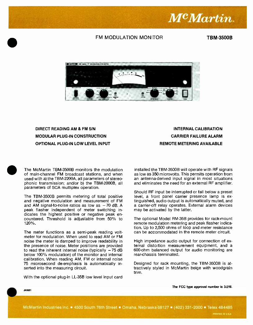
FM MODULATION MONITOR
DIRECT READING AM & FM SIN
MODULAR PLUG -IN CONSTRUCTION
OPTIONAL PLUG -IN LOW LEVEL INPUT
The McMartin TBM -3500B monitors the modulation of main -channel FM broadcast stations, and when used with a) the TBM- 2200A, all parameters of stereo- phonic transmission; and/or b) the TBM- 2000B, all parameters of SCA multiplex operation.
The TBM -3500B permits metering of total positive and negative modulation and measurement of FM and AM signal -to -noise ratios as low as - 70 dB. A peak flasher independent of meter switching in- dicates the highest positive or negative peak en- countered. Threshold is adjustable from 50% to 120 %.
The meter functions as a semi -peak reading volt- meter for modulation. When used to read AM or FM noise the meter is damped to improve readability in the presence of noise. Meter positions are provided to read the inherent internal noise (typically - 75 dB below 100% modulation) of the monitor and internal calibration. When reading AM, FM or internal noise 75 microsecond de- emphasis is automatically in- serted into the measuring circuit.
With the optional plug -in LL -35B low level input card
JAN/81
TBM-3500B
INTERNAL CALIBRATION
CARRIER FAILURE ALARM
REMOTE METERING AVAILABLE
installed the TBM -3500B will operate with RF signals as low as 350 microvolts. This permits operation from an antenna -derived input signal in most situations and eliminates the need for an external RF amplifier.
Should RF input be interrupted or fall below a preset level, a front panel carrier presence lamp is ex- tinguished, audio output is automatically muted, and a carrier -off relay operates. External alarm devices may be activated by the latter.
The optional Model RM -35B provides for rack -mount remote modulation metering and peak flasher indica- tion. Up to 2,500 ohms of loop and meter resistance can be accommodated in the remote meter circuit.
High imped:znce audio output for connection of ex- ternal distolion measurement equipment, and a 600 -ohm balanced output for audio monitoring are rear -chassis terminated.
Designed for rack mounting, the TBM -3500B is at- tractively styled in McMartin beige with woodgrain trim.
The FCC type approval number is 3-219.
McMartin Industries Inc. 4500 South 76th Street Omaha, Nebraska68127 (402) 331 -2000 Telex 484485
PRINTED IN U SA
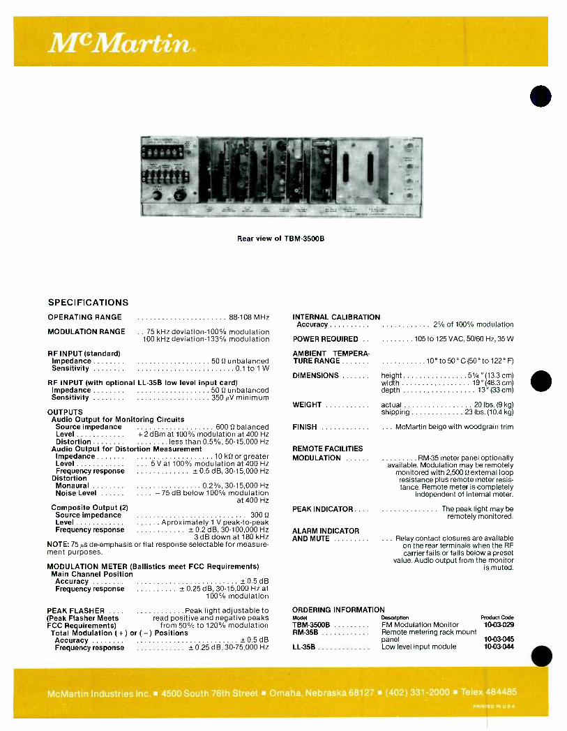
Rear view of TBM -3500B
SPECIFICATIONS
OPERATING RANGE 88 -108 MHz
MODULATION RANGE .. 75 kHz deviation -100% modulation 100 kHz deviation -133% modulation
RF INPUT(standard) Impedance 50 0 unbalanced Sensitivity 0 1 to 1 W
RF INPUT (with optional LL -35B low level input card) Impedance 50 ft unbalanced Sensitivity 350 µV minimum
OUTPUTS Audio Output for Monitoring Circuits Source impedance 600 0 balanced Level + 2 dBm at 100% modulation at 400 Hz Distortion less than 0.5 %, 50- 15,000 Hz
Audio Output for Distortion Measurement Impedance 10 kll or greater Level ... 5 V at 100% modulation at 400 Hz Frequency response ±0.5 dB, 30- 15,000 Hz
Distortion Monaural 0 2 %, 30- 15,000 Hz Noise Level .... - 75 dB below 100% modulation
at 400 Hz Composite Output (2) Source impedance 300 0 Level Aproximately 1 V peak -to -peak Frequency response ± 0.2 dB, 30- 100,000 Hz
3 dB down at 180 kHz NOTE: 75 µs de- emphasis or flat response selectable for measure- ment purposes.
MODULATION METER (Ballistics meet FCC Requirements) Main Channel Position
INTERNAL CALIBRATION Accuracy
POWER REQUIRED .
AMBIENT TEMPERA- TURE RANGE
DIMENSIONS
WEIGHT
FINISH
REMOTE FACILITIES MODULATION
PEAK INDICATOR ...
ALARM INDICATOR AND MUTE
2% of 100% modulation
105 to 125 VAC, 50/60 Hz, 35 W
10° to 50° C(50° to 122° F)
height 51/4 "(13.3 cm) width 19" (48.3 cm) depth 13 "(33 cm)
actual 20 lbs. (9 kg) shipping 23 lbs. (10.4 kg)
McMartin beige with woodgrain trim
RM -35 meter panel optionally available. Modulation may be remotely
monitored with 2,500 S2 external loop resistance plus remote meter resis- tance. Remote meter is completely
independent of internal meter.
The peak light may be remotely monitored.
Relay contact closures are available on the rear terminals when the RF carrier fails or falls below a preset
value. Audio output from the monitor is muted.
Accuracy + 0 5 dB Frequency response ±0.25 dB, 30- 15,000 Hz at
100% modulation
PEAK FLASHER Peak light adjustable to ORDERING INFORMATION (Peak Flasher Meets read positive and negative peaks Model Description Product Code
FCC Requirements) from 50% to 120% modulation TBM3500B FM Modulation Monitor 10- 03-029 Total Modulation ( +) or ( -) Positions RM -35B Remote metering rack mount Accuracy +05dB panel 10- 03-045 Frequency response + 0.25 dB, 30- 75,000 Hz LL-35B Low level input module 10-03 -044
McMartin Industries Inc. 4500 South 76th Street Omaha, Nebraska 68127 (402) 331 -2000 Telex 48
IN U 9j
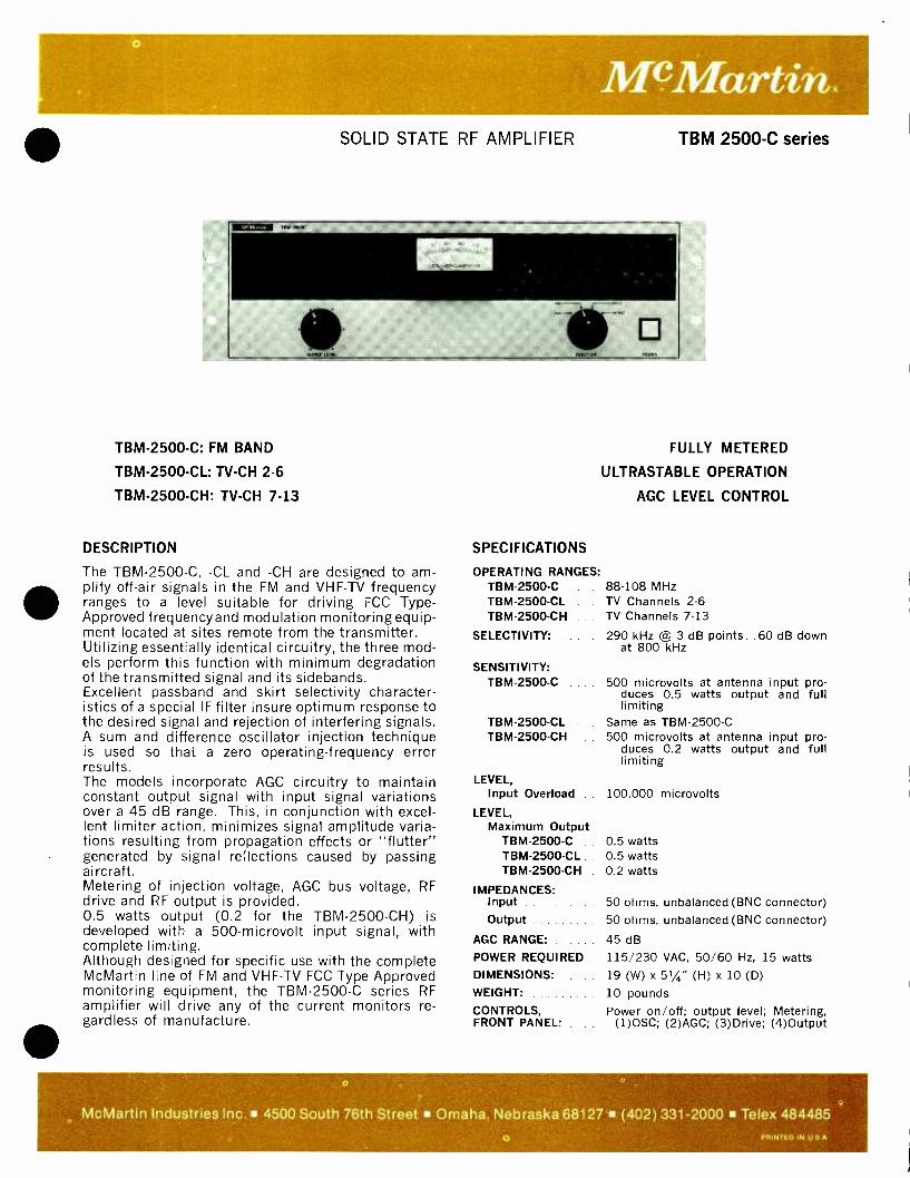
o
Mc Marti SOLID STATE RF AMPLIFIER TBM 2500 -C series
TBM-2500-C: FM BAND
TBM-2500-CL: TV-CH 2-6
TBM-2500-CH: TV-CH 7-13
DESCRIPTION
The TBM- 2500 -C, -CL and -CH are designed to am- plify off -air signals in the FM and VHF -TV frequency ranges to a level suitable for driving FCC Type - Approved frequencyand modulation monitoring equip- ment located at sites remote from the transmitter. Utilizing essentially identical circuitry, the three mod- els perform this function with minimum degradation of the transmitted signal and its sidebands. Excellent passband and skirt selectivity character- istics of a special IF filter insure optimum response to the desired signal and rejection of interfering signals. A sum and difference oscillator injection technique is used so that a zero operating- frequency error results. The models incorporate AGC circuitry to maintain constant output signal with input signal variations over a 45 dB range. This, in conjunction with excel- lent limiter action, minimizes signal amplitude varia- tions resulting from propagation effects or "flutter" generated by signal reflections caused by passing aircraft. Metering of injection voltage, AGC bus voltage, RF drive and RF output is provided. 0.5 watts output (0.2 for the TBM- 2500 -CH) is developed with a 500- microvolt input signal, with complete limiting. Although designed for specific use with the complete McMartin line of FM and VHF -TV FCC Type Approved monitoring equipment, the TBM- 2500 -C series RF amplifier will drive any of the current monitors re- gardless of manufacture.
FULLY METERED
ULTRASTABLE OPERATION
AGC LEVEL CONTROL
SPECIFICATIONS
OPERATING RANGES: TBM -2500 -C .... 88 -108 MHz TBM- 2500 -CL TV Channels 2 -6
TBM- 2500 -CH TV Channels 7 -13
SELECTIVITY:
SENSITIVITY: TBM- 2500 -C
290 kHz @ 3 dB points 60 dB down at 800 kHz
TBM-2500-CL TBM-2500-CH
LEVEL, Input Overload
LEVEL, Maximum Output
TBM- 2500 -C TBM -2500 -CL TBM- 2500 -CH
IMPEDANCES: Input Output
AGC RANGE:
POWER REQUIRED
DIMENSIONS:
WEIGHT:
CONTROLS, FRONT PANEL:
500 microvolts at antenna input pro- duces 0.5 watts output and full limiting
Same as TBM- 2500 -C
500 microvolts at antenna input pro- duces 0.2 watts output and full limiting
100,000 microvolts
0.5 watts 0.5 watts 0.2 watts
50 ohms, unbalanced (BNC connector) 50 ohms, unbalanced (BNC connector)
45 dB
115 230 VAC, 50;'60 Hz, 15 watts 19 (W) x 51/4" (H) x 10 (D)
10 pounds Power on 'off; output level; Metering,
(1)OSC; (2)AGC; (3)Drive; (4)Output
o
McMartin Industries Inc. 4500 South 76th Street Omaha, Nebraska 68127` (402) 331 -2000 Telex 484485
O PRINTED IN U S A
G

FM RELAY RECEIVER
NEW PTD (PRECISE TRACKING DECODER)
IMPROVED SENSITIVITY
GREATER RF DYNAMIC RANGE
STEREO /SCA PLUG -IN OPTIONS
The McMartin TBM -1005D is a 1 -5 channel crystal controlled FM relay receiver which supercedes the per- formance proved TBM -1000B series. The McMartin TBM -1003D is available for operation in the VHF -TV aural channels. Channel 2 through 6 and channel 7
through 13 only.
The McMartin TBM -1005D is a high performance FM relay receiver with an accurate wide band composite signal output. The receiver also provides stereo and /or SCA outputs by simple insertion of optional plug -in cards. Two cards may be accommodated. The optional STE -1 D stereo plug -in card provides a left and right channel output at a level of +8dbm (600 ohms), and provides accurate measurement of the stereo pilot injection level.
The optional SCA -2 -67D or SCA-2-41D SCA plug -in cards will provide an SCA audio output of +8dbm (600 ohms) and provide measurement of the SCA injection level plus monitoring of the modulation level, selectable by the front panel function switch. Two SCA plug -in cards may be used simultaneously with the second SCA card inserted in the mono or stereo socket.
The standard mono card incorporates a 15 kHz low - pass filter to remove the troublesome 19 kHz stereo signal from the audio which can otherwise create prob- lems if the signal is used for rebroadcast or recording.
The TBM -1005D utilizes a new concept in receiver design providing space age technology in which the
JUNE/79
FM range TBM -1005D
TV (VHF only) TBM -1003D
1 -5 CHANNEL CAPABILITIES
IMPROVED LINEARITY
FULLY METERED
PANEL MOUNTED MONITORING SPEAKER
receiver actually tracks the modulated signal from the FM transmitter providing accurate composite signals identical to what was originally transmitted.
The front end of the TBM -1005D is crystal controlled and utilizes a diode protected dual gate D -MOS field effect RF amplifier. This device has very linear AGC control providing greater than 50db gain reduction resulting in an overall tuner dynamic range of over 100db with minimum of cross modulation. The AGC does not produce any skewing or detuning of the RF circuits. All RF circuitry switching and tracking is per- formed by using Varactor tuning techniques. No switch contacts are used in RF circuits and each channel is tuned by a trimpot potentiometer controlled by the front panel function switch.
An entirely new IF system has been designed eliminat- ing the multisection 10.7 mHz IF band -pass filter. The TBM -1005D provides better selectivity to reject un- wanted signals and still provide accurate composite signals. Provisions are provided for the addition of an optional filter for exceptional high selectivity.
Adjustable squelch control of main channel and two SCA channels are provided. The two SCA squelch controls are mounted on the rear chassis and are adjustable from 3% to 10% injection levels.
The TBM -1005D and 1003D are rack mounted and styled in beige with wood grain trim.
McMartin Industries Inc. 4500 South 76th Street Omaha, Nebraska 68127 (402) 331 -2000 Telex 484485 PRINTED IN U S A
SPECIFICATIONS
MAIN CHANNEL: ANTENNA INPUT IMPEDANCE 50/72 ohm unbalanced
RANGE - TBM-1005D 88 -108 mHz TBM -1003D VHF -TV channels 2 -13
aural carriers SENSITIVITY - TBM-1005D 1 microvolt for 30db quieting (MONAURAL) 3 microvolts for 50db quieting
TBM -1003D (CH. 2-6) 1 5 microvolt for 30db quieting (CH. 7 -13) 3 microvolts for 30db quieting
SELECTIVITY- 50db alternate channel (Standard) TBM -1005D 70db with optional filter
CAPTURE RATIO .. 1.5db or less
COMPOSITE OUT- PUT 1.5v (P -P) adjustable
COMPOSITE FREQUENCY RESPONSE ±0.3db 10 -75000 Hz
PROGRAM AUDIO OUTPUTS: MONAURAL PLUG -IN CARD (standard)
Audio output impedance 600 ohm balanced
Output level +8dbm @ 100% mod. 400 Hz
Frequency response ±0.5db 30 -15000 Hz
De- emphasis 75 microsecond standard 25 or 50 microsecond available
S/N ratio Typically 65db or greater below 100% mod. 400 Hz
Distortion THD 0.5% or less (30 -15000 Hz)
19 kHz pilot carrier rejection 65db or greater
STEREO PLUG -IN CARD STE -1D (optional) Audio output impedance .600 ohm balanced right and left channel
Output level +8dbm right and left channel
Frequency response +0.5db 30 -15000 Hz
De- emphasis 75 microsecond standard 25 or 50 microsecond available
S/N ratio 55db or greater below 100% Modulation 400 Hz left or right Ch.
Distortion THD 1°/ or less 30 -15000 Hz
Channel separation 40db 30 -10000 Hz
30db 10000 -15,000 Hz
Pilot injection metering ±1% accuracy when receiver is
completely limited.
SCA rejection 65db or greater
SCA PLUG -IN CARD SCA -2 -67D (optional)
Audio output impedance 600 ohm balanced
Output level +8dbm 100°/0 modulation ( ±6 kHz deviation) @ 200 Hz
Frequency response ±3db -30 -6000 Hz with modified
150 microsecond de- emphasis
.Typical 60db below 100% modulation referenced @ 200 Hz
1% or less 30 -6000 Hz- Typically 0.5% at 400 Hz
S/N ratio
Distortion
SCA injection metering
SCA modulation metering
±1% accuracy when receiver is completely limited
Meter is semi -peax reading and referenced at ±6 kHz deviation
for 100% modulation SCA- PLUG -IN CARD SCA -2-41D (optional)
Specifications are generally the same as for the SCA -2 -67 kHz plug -in card excepting the 100% modulation is referenced at ±4 kHz deviation. NOTE: Other SCA frequencies are available.
METERING FUNCTIONS: Relative RF level, total modulation,
pilot injection, SCA injection and SCA modulation
POWER REQUIRED: . 120/240 VAC 50/60 Hz -25 watts
DIMENSIONS: width 19" (48.3 cm) height 31/2" (8.9 cm) depth 12" (30.9 cm)
WEIGHT: actual 7.7 pounds (3.5 kg) shipping 12.7 pounds (5.8 kg)
FINISH: McMartin beige with woodgrain trim
PLUG -IN ACCESSORIES: STE -1D Stereo demodulator card
SCA- 2 -67D 67 kHz SCA demodulator card
SCA- 2 -41D: 41 kHz SCA demodulator card
NOTE: Other SCA frequencies available. The TBM -1005D and 1003D are
normally supplied with the plug -in mono card.
NB -1: Optional band -pass filter
REAR CHASSIS TERMINATION: Antenna (BNC), composite output
(BNC) monaural or stereo left, SCA -2 or stereo right, SCA -1 and carrier
relay contacts (NO) or (NC) RELAY CONTACTS RATING 0.5 am. lu 24 volts
ORDERING INFORMATION: Model Description Product Code
TBM -1005D 5 Channel Relay Runner 88 to 108 mHz 10 -03 -009 (with one crystal) Additional Crystals (specify frequency)
TBM -1003D TV Aural Receiver Channel 2 -13
STE -1D Stereo Plug in Demodulator Card 10 -03 -012
10 -03 -010 SCA-2-41 D SCA Plug in Demodulator
Card 41KH2
SCA -2 -67D SCA Plug in Demodulator Card 67KH2 10 -03 -011
McMartin Industries Inc. 4500 South 76th Street Omaha, Nebraska 68127. (402) 331/2000 Telex 484485 PRINTED IN U
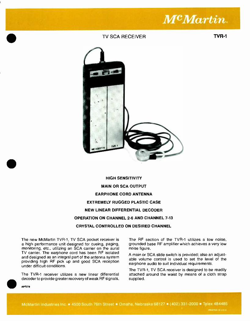
TV SCA RECEIVER
HIGH SENSITIVITY
MAIN OR SCA OUTPUT
EARPHONE CORD ANTENNA
EXTREMELY RUGGED PLASTIC CASE
NEW LINEAR DIFFERENTIAL DECODER
OPERATION ON CHANNEL 2 -6 AND CHANNEL 7 -13
CRYSTAL CONTROLLED ON DESIRED CHANNEL
The new McMartin TVR -1, TV SCA pocket receiver is a high performance unit designed for cueing, paging, monitoring, etc., utilizing an SCA carrier on the aural TV carrier. The earphone cord has been RF isolated and designed as an integral part of the antenna system providing high RF pick up and good SCA reception under difficult conditions.
The TVR -1 receiver utilizes a new linear differential decoder to provide greater recovery of weak RF signals.
APR/79
TV R-1
The RF section of the TVR -1 utilizes a low noise, grounded base RF amplifier which achieves a very low noise figure.
A main or SCA slide switch is provided; also an adjust- able volume control is used to set the level of the earphone audio to suit individual requirements.
The TVR -1, TV SCA receiver is designed to be readily attached around the waist by means of a cloth strap supplied.
McMartin Industries Inc. 4500 South 76th Street Omaha, Nebraska 68127 (402) 331 -2000 Telex 484485 PRINTED IN U S A
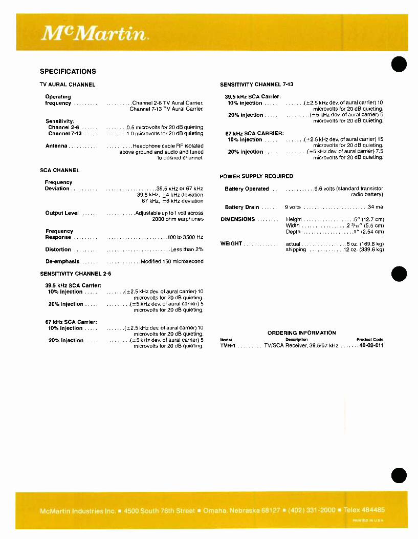
SPECIFICATIONS
TV AURAL CHANNEL
Operating frequency Channel 2 -6 TV Aural Carrier.
Channel 7 -13 TV Aural Carrier.
Sensitivity: Channel 2 -6 0.5 microvolts for 20 dB quieting Channel 7 -13 1.0 microvolts for 20 dB quieting
Antenna Headphone cable RF isolated above ground and audio and tuned
to desired channel.
SCA CHANNEL
Frequency Deviation 39.5 kHz or 67 kHz
39.5 kHz, +4 kHz deviation 67 kHz, ±6 kHz deviation
Output Level Adjustable up to 1 volt across 2000 ohm earphones
Frequency Response 100 to 3500 Hz
Distortion Less than 2%
De- emphasis Modified 150 microsecond
SENSITIVITY CHANNEL 2 -6
39.5 kHz SCA Carrier: 10% injection ( ±2.5 kHz dev. of aural carrier) 10
microvolts for 20 dB quieting. 20% injection ( ±5 kHz dev. of aural carrier) 5
microvolts for 20 dB quieting.
67 kHz SCA Carrier: 10% injection
20% injection
( +2 5 kHz dev. of aural carrier) 10
microvolts for 20 dB quieting. (5 kHz dev. of aural carrier) 5
microvolts for 20 dB quieting.
SENSITIVITY CHANNEL 7 -13
39.5 kHz SCA Carrier: 10% injection
20% injection
( ±2 5 kHz dev. of aural carrier) 10
microvolts for 20 dB quieting. (4-5 kHz dev. of aural carrier) 5
microvolts for 20 dB quieting.
67 kHz SCA CARRIER: 10% injection ( ±2.5 kHz dev. of aural carrier) 15
microvolts for 20 dB quieting. 20% injection ( ±5 kHz dev. of aural carrier) 7.5
microvolts for 20 dB quieting.
POWER SUPPLY REQUIRED
Battery Operated .. 9.6 volts (standard transistor radio battery)
Battery Drain 9 volts 34 ma
DIMENSIONS Height 5" (12.7 cm) Width 2 3/16" (5.5 cm) Depth 1" (2.54 cm)
WEIGHT actual 6 oz. (169.8 kg) shipping 12 oz. (339.6 kg)
ORDERING INFORMATION Model Description Product Code
TVR -1 TV /SCA Receiver, 39.5/67 kHz . 40 -02 -011
McMartin Industries Inc. 4500 South 76th Street Omaha. Nebraska 68127 (402) 331 -2000 Telex 484485 PRINTED IN U S A
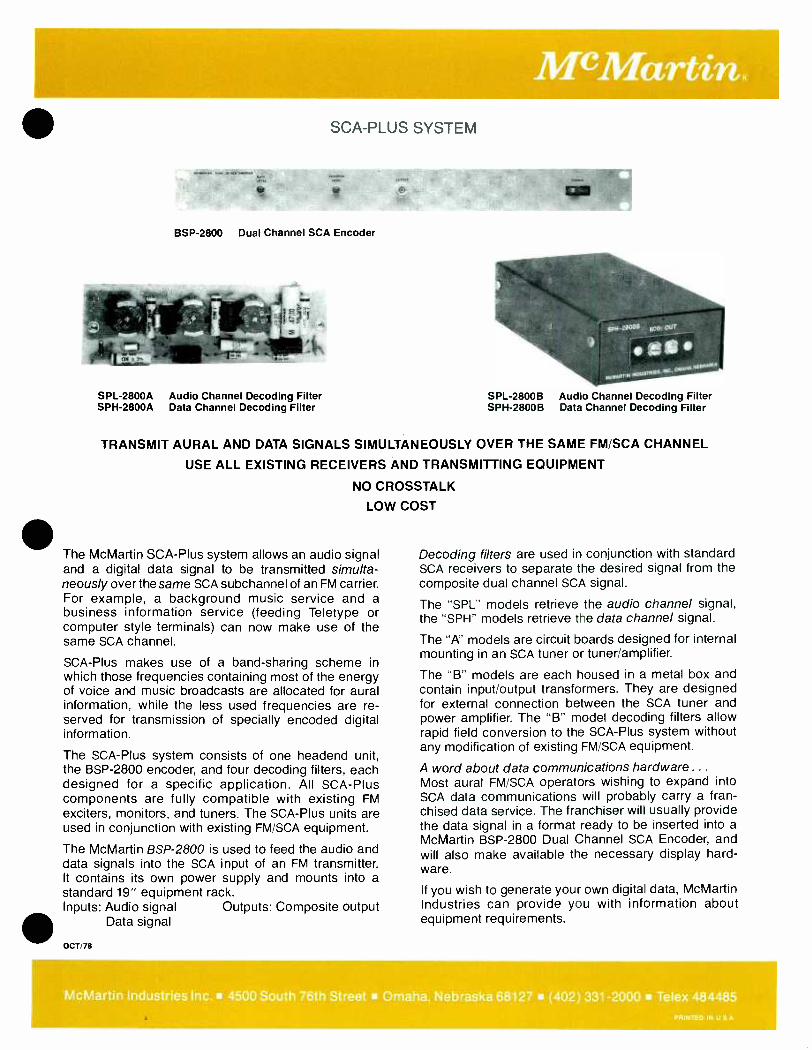
SCA -PLUS SYSTEM
BSP -2800 Dual Channel SCA Encoder
SPL -2800A Audio Channel Decoding Filter SPH -2800A Data Channel Decoding Filter
SPL -2800B Audio Channel Decoding Filter SPH -2800B Data Channel Decoding Filter
TRANSMIT AURAL AND DATA SIGNALS SIMULTANEOUSLY OVER THE SAME FM /SCA CHANNEL
USE ALL EXISTING RECEIVERS AND TRANSMITTING EQUIPMENT
NO CROSSTALK
LOW COST
The McMartin SCA -Plus system allows an audio signal and a digital data signal to be transmitted simulta- neously over the same SCA subchannel of an FM carrier. For example, a background music service and a business information service (feeding Teletype or computer style terminals) can now make use of the same SCA channel.
SCA -Plus makes use of a band -sharing scheme in which those frequencies containing most of the energy of voice and music broadcasts are allocated for aural information, while the less used frequencies are re- served for transmission of specially encoded digital information.
The SCA -Plus system consists of one headend unit, the BSP -2800 encoder, and four decoding filters, each designed for a specific application. All SCA -Plus components are fully compatible with existing FM exciters, monitors, and tuners. The SCA -Plus units are used in conjunction with existing FM /SCA equipment.
The McMartin BSP -2800 is used to feed the audio and data signals into the SCA input of an FM transmitter. It contains its own power supply and mounts into a standard 19" equipment rack. Inputs: Audio signal Outputs: Composite output
Data signal
OCT/78
Decoding filters are used in conjunction with standard SCA receivers to separate the desired signal from the composite dual channel SCA signal.
The "SPL" models retrieve the audio channel signal, the "SPH" models retrieve the data channel signal.
The "A" models are circuit boards designed for internal mounting in an SCA tuner or tuner /amplifier.
The "B" models are each housed in a metal box and contain input /output transformers. They are designed for external connection between the SCA tuner and power amplifier. The "B" model decoding filters allow rapid field conversion to the SCA -Plus system without any modification of existing FM /SCA equipment.
A word about data communications hardware .. .
Most aural FM /SCA operators wishing to expand into SCA data communications will probably carry a fran- chised data service. The franchiser will usually provide the data signal in a format ready to be inserted into a McMartin BSP -2800 Dual Channel SCA Encoder, and will also make available the necessary display hard- ware.
If you wish to generate your own digital data, McMartin Industries can provide you with information about equipment requirements.
McMartin Industries Inc. 4500 South 76th Street Omaha, Nebraska 68127 (402) 331 -2000 Telex 484485 PRINTED IN U S A
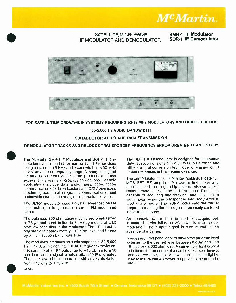
SATELLITE /MICROWAVE SMR -1 IF Modulator IF MODULATOR AND DEMODULATOR SDR -1 IF Demodulator
411.
ï
Mr Marton. sita i t. . m-
O
FOR SATELLITE /MICROWAVE IF SYSTEMS REQUIRING 52 -88 MHz MODULATORS AND DEMODULATORS
50 -5,000 Hz AUDIO BANDWIDTH
SUITABLE FOR AUDIO AND DATA TRANSMISSION
DEMODULATOR TRACKS AND RELOCKS TRANSPONDER FREQUENCY ERROR GREATER THAN t50 KHz
The McMartin SMR -1 IF Modulator and SDR -1 IF De- modulator are intended for narrow band FM services using a maximum 5 KHz audio bandwidth in a 52 MHz - 88 MHz carrier frequency range. Although designed for satellite communications, the products are also excellent in terrestrial microwave applications. Possible applications include data and /or aural coordination communications for broadcasters and CATV operators, medium grade aural program communications, and nationwide distribution of digital information services.
The SMR -1 modulator uses a crystal referenced phase lock technique to generate a direct FM modulated signal.
The balanced 600 ohm audio input is pre- emphasized at 75 µs and band limited to 6 kHz by means of a LC
type low pass filter in the modulator. The RF output is
adjustable to approximately +10 dBm level and filtered by a multi -section band pass filter.
The modulator produces an audio response of 50 -5,000 Hz, ±1 dB, with a nominal ±10 kHz frequency deviation. It is capable of an RF output up to +10 dBm into a 50 ohm load, and its signal to noise ratio is 60dB or greater. The unit is available for operation with any FM deviation from ±10 kHz to ±75 kHz.
APR/79
The SDR -1 IF Demodulator is designed for continuous duty reception of signals in a 52 to 88 MHz range and utilizes a dual conversion technique for elimination of image responses in this frequency range.
The demodulator consists of a low noise dual gate "D" MOS FET RF amplifier. A discreet first mixer and amplifier feed the single chip second mixer /amplifier/ limiter /demodulator and an audio amplifier. The unit is
capable of acquiring and tracking, and relocking, a signal even when the transponder frequency error is ±50 kHz or more. The SDR -1 locks onto the carrier frequency insuring that the signal is precisely centered in the IF pass band.
An automatic sweep circuit is used to reacquire lock in case of carrier failure or AC power loss to the de- modulator. The output signal is also muted in the absence of a carrier.
A recessed front panel control allows the program level to be set to the desired level between 0 dBm and +18 dBm across a 600 ohm load. A carrier "on" light is used to indicate the presence of a carrier of suitable level to produce frequency lock. A power "on" indicator light is
used to insure that AC power is applied to the demodu- lator.
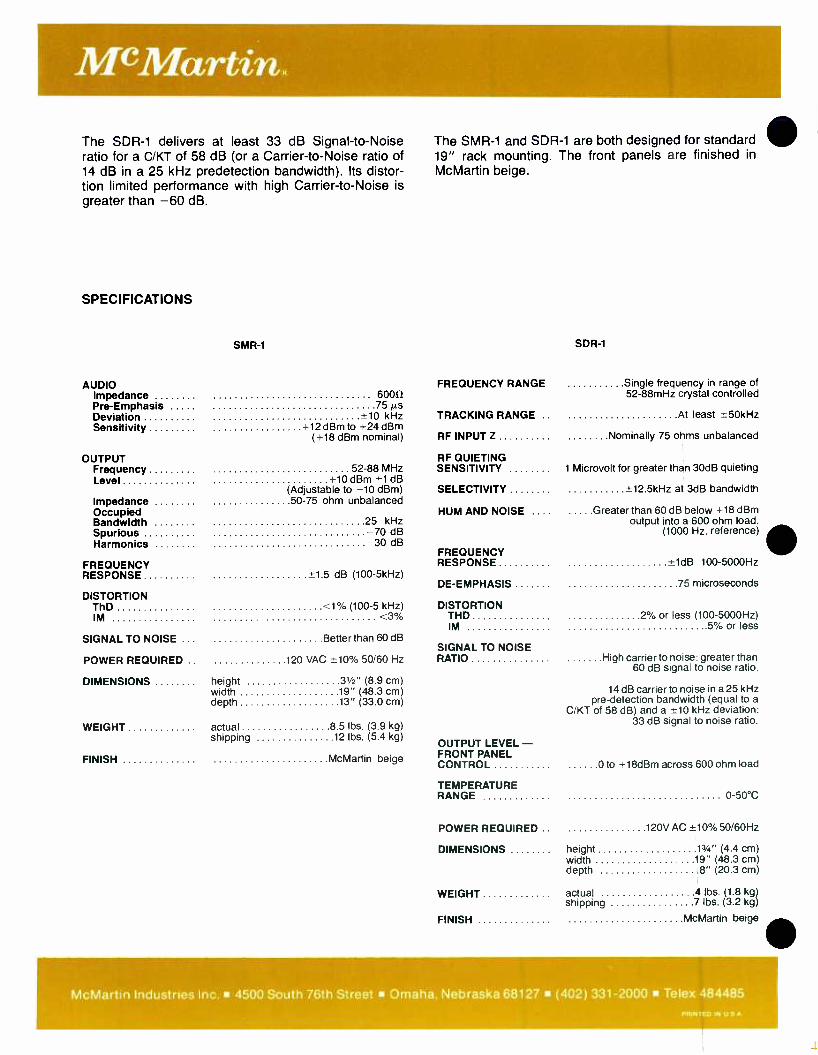
McMartin.
The SDR -1 delivers at least 33 dB Signal -to -Noise ratio for a C /KT of 58 dB (or a Carrier -to -Noise ratio of 14 dB in a 25 kHz predetection bandwidth). Its distor- tion limited performance with high Carrier -to -Noise is greater than -60 dB.
SPECIFICATIONS
SMR-1
AUDIO Impedance j.
Pre -Emphasis 75 µs Deviation ±10 kHz Sensitivity +12 dBm to +24 dBm
( +18 dBm nominal)
OUTPUT Frequency 52 -88 MHz Level +10 dBm ±1 dB
(Adjustable to 10 dBm) Impedance 50 -75 ohm unbalanced Occupied Bandwidth 25 kHz Spurious -70 dB Harmonics -30 dB
FREQUENCY RESPONSE X1.5 dB (100 -5kHz)
DISTORTION ThD <1% (100 -5 kHz) IM <3%
SIGNAL TO NOISE ... Better than 60 dB
POWER REQUIRED .. 120 VAC *10% 50/60 Hz
DIMENSIONS height 31/2" (8.9 cm) width 19" (48.3 cm) depth 13" (33.0 cm)
WEIGHT actual 8.5 lbs. (3.9 kg) shipping 12 lbs. (5.4 kg)
FINISH McMartin beige
The SMR -1 and SDR -1 are both designed for standard ID 19" rack mounting. The front panels are finished in
McMartin beige.
FREQUENCY RANGE
TRACKING RANGE .
RF INPUT Z
RF QUIETING SENSITIVITY
SELECTIVITY
HUM AND NOISE ... .
FREQUENCY RESPONSE
DE- EMPHASIS
DISTORTION THD IM
SIGNAL TO NOISE RATIO
OUTPUT LEVEL - FRONT PANEL CONTROL
TEMPERATURE RANGE
POWER REQUIRED .
DIMENSIONS
WEIGHT
FINISH
SDR -1
Single frequency in range of 52 -88mHz crystal controlled
At least ±50kHz
Nominally 75 ohms unbalanced
1 Microvolt for greater than 30dB quieting
+12.5kHz at 3dB bandwidth
Greater than 60 dB below +18 dBm output into a 600 ohm load.
(1000 Hz. reference)
±1dB 100- 5000Hz
75 microseconds
2% or less (100- 5000Hz) .5% or less
High carrier to noise: greater than 60 dB signal to noise ratio.
14 dB carrier to noise in a 25 kHz pre- detection bandwidth (equal to a
C /KT of 58 dB) and a ±10 kHz deviation: 33 dB signal to noise ratio.
0 to +18dBm across 600 ohm load
0 -50 °C
120V AC ±10 %50 /60Hz
height 13/4" (4.4 cm) width 19" (48.3 cm) depth 8" (20.3 cm)
actual 4 lbs. (1.8 kg shipping 7 lbs. (3.2 kg
McMartin beige
McMartin Industries Inc. 4500 South 76th Street Omaha, Nebraska 68127 (402) 331 -2000 Telex 484485 PRINTED IN U S A
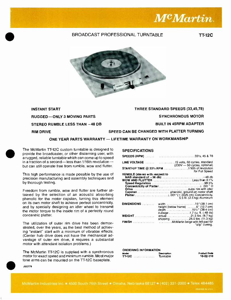
BROADCAST PROFESSIONAL TURNTABLE
INSTANT START
RUGGED -ONLY 3 MOVING PARTS
STEREO RUMBLE LESS THAN 48 DB
RIM DRIVE
TT-12C
THREE STANDARD SPEEDS (33,45,78)
SYNCHRONOUS MOTOR
BUILT IN 45RPM ADAPTER
SPEED CAN BE CHANGED WITH PLATTER TURNING
ONE YEAR PARTS WARRANTY - LIFETIME WARRANTY ON WORKMANSHIP
The McMartin TT -12C custom turntable is designed to provide the broadcaster, or other discerning user, with a rugged, reliable turntable which can come up to speed in a fraction of a second -less than 1/16th revolution - but can still operate free from rumble, wow and flutter.
This high performance is made possible by the use of precision manufacturing and assembly techniques and by thorough testing.
Freedom from rumble, wow and flutter are further at- tained by the selection of an acoustic absorbing phenolic for the motor capstan, turning this element on its own motor shaft to achieve perfect concentricity, and by specially designing an idler wheel to transmit the motor torque to the inside rim of a perfectly round concentric platter.
The utilization of outer rim drive has been demon- strated, over the years, as the best method of achiev- ing "instant" start with a minimum of vibration effects. (Center hub drive does not have the mechanical ad- vantage of outer rim drive, it requires a substantial motor with attendant isolation problems.)
The McMartin TT -12C is supplied with a synchronous motor for exact speed and minimum rumble. Most major tone arms can be mounted on the TT -12C baseplate.
JULY /79
SPECIFICATIONS
SPEEDS (RPM) 331/3, 45 & 78
LINE VOLTAGE 15 volts, 60 cycles, standard (230V - 50 cycles, optional)
START -UP TIME @ 33% RPM 1/16th of revolution for Full Speed
RUMBLE (stereo with respect to NAB standard of 36 db) 48 db
WOW AND FLUTTER Less than 0.1% Speed Regulation 99.5% Concentricity of Platter 4- 001 " D Drive outer rim with idler Capstan phenolic, ground on motor shaft Platter +.001"(4_-.0025 cm) Concentricity,
5.5 lb. (2.5 kg) Aluminum
width 15" (38.1 cm) height (below frame) 5" (12.7 cm) depth 151/2" (39.4 cm) cubage 1.7 cu. ft. (.48 ds) actual 21.5 lbs. (9.7 kg) shipping 25.0 lbs. (11.3 kg)
McMartin beige with felt pad for "slip" cueing.
DIMENSIONS
WEIGHT
FINISH
ORDERING INFORMATION Model Description TT-12C Turntable
Product Code 10-02 -110
McMartin Industries Inc. 4500 South 76th Street Omaha, Nebraska 68127 (402) 331 -2000 Tel
efllNT.IcDIN,USA'

HIGH SPEED TAPE ERASER
ERASES CLEAN
SIMPLE "HANDS OFF" OPERATION
SAVES TIME AND IMPROVES QUALITY
FAST - 4 SECONDS FOR MOST TAPES
HANDLES AUDIO I VIDEO REELS AND CARTRIDGES
The McMartin TE -70 and TE -105 bulk tape erasers are designed to automate your tape erasing operations and to eliminate residual noise problems.
Model TE -70 can handle cartridges and reels up to seven inches in diameter. Model TE -105 can also handle tapes up to 101/2 inches in diameter.
Operation is simple and efficient. Just press the
SPECIFICATIONS
POWER
ERASER LEVEL
METHOD OF OPERATION
THERMAL PROTECTION
117 VAC, 60 Hz 220 VAC, 50 Hz
-80 dB nominal
Tapes are passed on a continuous belt over high flux coils and deposited at
end of machine.
Overheating is prevented by auto- matic cut -off switch, which reactivates
eraser after cool -down period.
TE-70 TE-105
power button and put any reel or cassette on the endless belt. In four seconds it delives a clean, "no- whump" erasure that will meet stringent recording standards.
With the TE -70 or TE -105, tape erasing is no longer drudgery. Tapes need not pile up because no one wants to tackle hand erasing.
TE -105 height 5 "(12.7 cm) width 271/2 " (69.9 cm) depth 131/4 " (33.7 cm) belt width 11" (27.9 cm)
WEIGHT TE -70 actual 60 lbs. (27.2 kg)
shipping 65 lbs. (29.5 kg)
TE -105 actual 80 lbs. (36.2 kg) shipping 88 lbs. (39.9 kg)
FINISH light tan
DIMENSIONS TE -70 height 5" (12.7 cm) ORDERING INFORMATION
width 27" (68.6 cm) Model Description Product Code depth 10" (25.4 cm) TE -70 High Speed Tape Eraser 10-02-114 belt width 71/2 " (19 cm) TE -105 High Speed Tape Eraser 10-02-115
FEB180
McMartin Industries Inc. 4500 South 76th Street Omaha, Nebraska 68127 (402) 331 -2000 Telex 48448_
MIN D IN
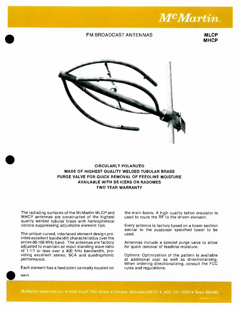
FM BROADCAST ANTENNAS
CIRCULARLY POLARIZED MADE OF HIGHEST QUALITY WELDED TUBULAR BRASS
PURGE VALVE FOR QUICK REMOVAL OF FEEDLINE MOISTURE AVAILABLE WITH DE -ICERS OR RADOMES
TWO YEAR WARRANTY
The radiating surfaces of the McMartin MLCP and MHCP antennas are constructed of the highest quality welded tubular brass with hemispherical corona suppressing adjustable element tips.
The unique curved, interlaced element design pro- vides excellent bandwidth characteristics over the entire 88 -108 MHz band. The antennas are factory adjusted to maintain an input standing wave ratio of 1.1:1 or less over a 400 KHz bandwidth, pro- viding excellent stereo, SCA and quadraphonic performance.
Each element has a feed point centrally located on
SEP /79
MLCP MHCP
the main boom. A high quality teflon insulator is used to route the RF to the driven element.
Every antenna is factory tuned on a tower section similar to the customer specified tower to be used.
Antennas include a special purge valve to allow for quick removal of feedline moisture.
Options: Optimization of the pattern is available at additional cost as well as directionalizing. When ordering directionalizing, consult the FCC rules and regulations.
McMartin Industries Inc. 4500 South 76th Street Omaha. Nebraska 68127 (402) 331 -2000 Telex 484485 CnV'Fi`
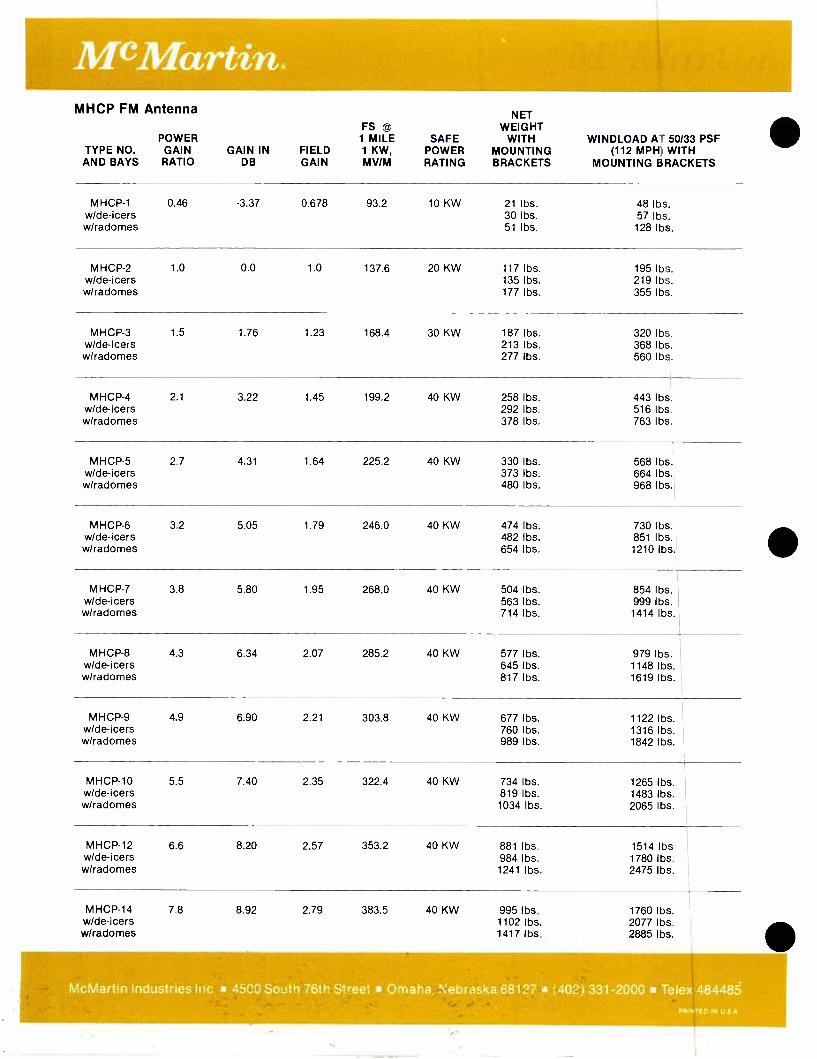
MHCP FM Antenna
POWER TYPE NO. GAIN AND BAYS RATIO
GAIN IN DB
FIELD GAIN
FS @
1 MILE 1 KW, MV /M
SAFE POWER RATING
NET WEIGHT
WITH MOUNTING BRACKETS
WINDLOAD AT 50/33 PSF (112 MPH) WITH
MOUNTING BRACKETS
MHCP-1 w/de-icers w/radomes
0.46 -3.37 0.678 93.2 10 KW 21 lbs. 30 lbs. 51 lbs.
48 lbs. 57 lbs. 128 lbs.
MHCP-2 w/de-icers w/radomes
1.0 0.0 1.0 137.6 20 KW 117 lbs. 135 lbs. 177 lbs.
195 lbs. 219 lbs. 355 lbs.
MHCP-3 w/de-icers w/radomes
1.5 1.76 1.23 168.4 30 KW 187 lbs. 213 lbs. 277 lbs.
320 lbs. 368 I bs. 560 I bs.
MHCP-4 w/de-icers w/radomes
2.1 3.22 1.45 199.2 40 KW 258 lbs. 292 I bs. 378 lbs.
443 lbs. 516 lbs. 763 lbs.
MHCP-5 w/de-icers w/radomes
2.7 4.31 1.64 225.2 40 KW 330 lbs. 373 I bs. 480 lbs.
568 lbs. 664 I bs. 968 lbs.
MHCP-6 w/de-icers w/radomes
3.2 5.05 1.79 246.0 40 KW 474 lbs. 482 lbs. 654 lbs.
730 lbs. 851 lbs. 1210 lbs.
MHCP-7 w/de-icers w/radomes
3.8 5.80 1.95 268.0 40 KW 504 lbs. 563 lbs. 714 lbs.
854 lbs. 999 lbs. 1414 lbs.
MHCP-8 w/de-icers w/radomes
4.3 6.34 2.07 285.2 40 KW 577 lbs. 645 Ibs. 817 lbs.
979 lbs. 1148 lbs. 1619 lbs.
MHCP-9 w/de-icers w/radomes
4.9 6.90 2.21 303.8 40 KW 677 lbs. 760 lbs. 989 lbs.
1122 lbs. 1316 lbs. 1842 lbs.
MHCP-10 w/de-icers w/radomes
5.5 7.40 2.35 322.4 40 KW 734 lbs. 819 lbs. 1034 lbs.
1265 lbs. 1483 lbs. 2065 lbs.
MHCP-12 w/de-icers w/radomes
6.6 8.20 2.57 353.2 40 KW 881 lbs. 984 lbs.
1241 lbs.
1514 lbs 1780 lbs. 2475 lbs.
MHCP-14 w/de-icers w/radomes
7.8 8.92 2.79 383.5 40 KW 995 lbs. 1102 lbs. 1417 lbs.
1760 lbs. 2077 lbs. 2885 lbs.
McMartin Industries Inc. 4500 South 76th Street Omaha. Nebraska 68127 (402) 331 -2000 Telex 484485 PRINTED IN U S A

SUPER HIGH POWER ANTENNA MSHCP
Circularly Polarized
EXTREMELY BROAD BANDWIDTH
CIRCULARITY OF PATTERN ±1 dB
HEAVY RUGGED BRASS CONSTRUCTION
TWO YEAR WARRANTY
With a power rating of 30 kW per bay and a total antenna rating of 80 kW, the McMartin super high power antenna will accept the output of any currently produced high power transmitter. An extremely large surface area designed into this antenna virtually eliminates the common problems related to corona and arcing. With the greatly reduced surface poten- tials, power levels as high as 30 kW per bay are easily handled during the most severe weather conditions. The massive antenna construction provides for an excellent low "Q" condition resulting in a superior broad -band performance characteristic.
JUN/80
The unique antenna design, although simple in con- struction, provides the best possible radiating system available. The feed system between the bays is 61/8 inch diameter line. The attachment of the elements to the line sections is by means of a heavy brass casting. The four elements are constructed of 3 inch diameter heavy duty brass tubing. The center support boom is pressurized to the feed point from the same system which pressurizes the feed line. Each antenna is equipped with an overpressure relief valve allowing easy purging to remove moisture as well as preventing over pressurization due to pres- surizing equipment failure.
McMartin Industries Inc. 4500 South 76th Street Omaha, Nebraska 68127 (402) 331 -2000 Telex 4844
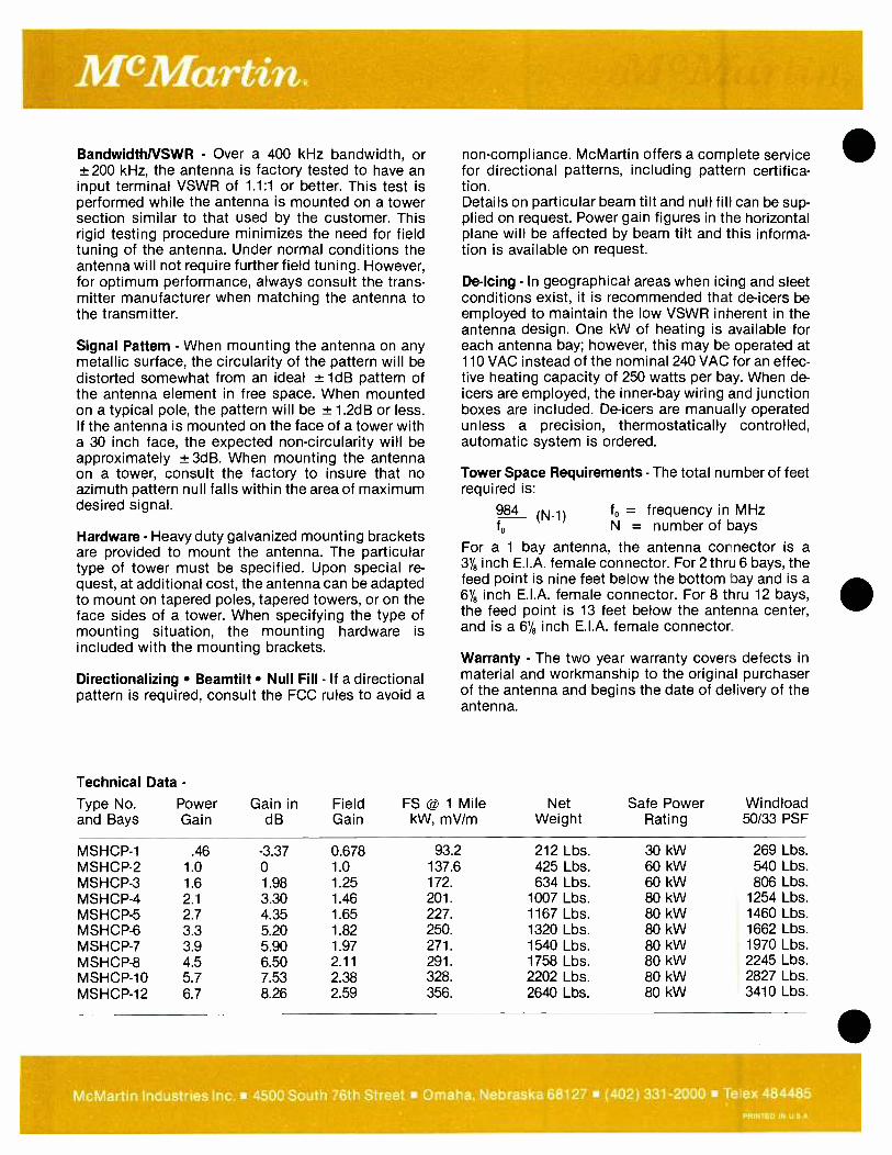
BandwidthNSWR - Over a 400 kHz bandwidth, or ±200 kHz, the antenna is factory tested to have an input terminal VSWR of 1.1:1 or better. This test is performed while the antenna is mounted on a tower section similar to that used by the customer. This rigid testing procedure minimizes the need for field tuning of the antenna. Under normal conditions the antenna will not require further field tuning. However, for optimum performance, always consult the trans- mitter manufacturer when matching the antenna to the transmitter.
Signal Pattern - When mounting the antenna on any metallic surface, the circularity of the pattern will be distorted somewhat from an ideal ± 1dB pattern of the antenna element in free space. When mounted on a typical pole, the pattern will be ± 1.2dB or less. If the antenna is mounted on the face of a tower with a 30 inch face, the expected non -circularity will be approximately ±3dB. When mounting the antenna on a tower, consult the factory to insure that no azimuth pattern null falls within the area of maximum desired signal.
Hardware Heavy duty galvanized mounting brackets are provided to mount the antenna. The particular type of tower must be specified. Upon special re- quest, at additional cost, the antenna can be adapted to mount on tapered poles, tapered towers, or on the face sides of a tower. When specifying the type of mounting situation, the mounting hardware is included with the mounting brackets.
Directionalizing Beamtilt Null Fill If a directional pattern is required, consult the FCC rules to avoid a
Technical Data -
non -compliance. McMartin offers a complete service for directional patterns, including pattern certifica- tion. Details on particular beam tilt and null fill can be sup- plied on request. Power gain figures in the horizontal plane will be affected by beam tilt and this informa- tion is available on request.
De -Icing - In geographical areas when icing and sleet conditions exist, it is recommended that de -icers be employed to maintain the low VSWR inherent in the antenna design. One kW of heating is available for each antenna bay; however, this may be operated at 110 VAC instead of the nominal 240 VAC for an effec- tive heating capacity of 250 watts per bay. When de- icers are employed, the inner -bay wiring and junction boxes are included. De -icers are manually operated unless a precision, thermostatically controlled, automatic system is ordered.
Tower Space Requirements - The total number of feet required is:
984 (N -1) fD = frequency in MHz fD N = number of bays
For a 1 bay antenna, the antenna connector is a aye inch E.I.A. female connector. For 2 thru 6 bays, the feed point is nine feet below the bottom bay and is a 61/e inch E.I.A. female connector. For 8 thru 12 bays, the feed point is 13 feet below the antenna center, and is a 6y8 inch E.I.A. female connector.
Warranty The two year warranty covers defects in material and workmanship to the original purchaser of the antenna and begins the date of delivery of the antenna.
Type No. and Bays
Power Gain
Gain in dB
Field Gain
FS @ 1 Mile kW, mV /m
Net Weight
Safe Power Rating
Windload 50/33 PSF
MSHCP-1 .46 -3.37 0.678 93.2 212 Lbs. 30 kW 269 Lbs. MSHCP-2 1.0 0 1.0 137.6 425 Lbs. 60 kW 540 Lbs. MSHCP-3 1.6 1.98 1.25 172. 634 Lbs. 60 kW 806 Lbs. MSHCP-4 2.1 3.30 1.46 201. 1007 Lbs. 80 kW 1254 Lbs. MSHCP-5 2.7 4.35 1.65 227. 1167 Lbs. 80 kW 1460 Lbs. MSHCP-6 3.3 5.20 1.82 250. 1320 Lbs. 80 kW 1662 Lbs. MSHCP-7 3.9 5.90 1.97 271. 1540 Lbs. 80 kW 1970 Lbs. MSHCP-8 4.5 6.50 2.11 291. 1758 Lbs. 80 kW 2245 Lbs. MSHCP-10 5.7 7.53 2.38 328. 2202 Lbs. 80 kW 2827 Lbs. MSHCP-12 6.7 8.26 2.59 356. 2640 Lbs. 80 kW 3410 Lbs.
McMartin Industries Inc. 4500 South 76th Street Omaha, Nebraska 68127 (402) 331 -2000 Te ex 484485 PRINTED IN U S A

TERMS AND CONDITIONS OF SALE
1. PRICE Prices of equipment are based on a cash transaction and are FOB Omaha, Nebraska, or point of shipment. McMartin may adjust the price of any of the equipment covered by this order to McMartin's current price in effect immediately prior to shipment except that, in the case of equipment manufactured by McMartin, if (a) this order is accompanied by a down payment of at least 25% of the total price of the equipment described herein and shipment is made within 90 days after McMartin's acceptance of this order, or (b) this order is herein designated as contingent upon Issuance of a construction permit by the Federal Communications Commission and is accompanied by a down payment of at least 5% of the total price of the equipment described herein and shipment is made within 6 months after McMartin's acceptance of this order, no price increases shall be made on McMartin manufactured equipment. All vendor manufactured equipment will be at the price in effect at time order is made firm.
2. CONTINGENT ORDERS: If this order is herein designated as being contingent, Purchaser represents it as pending, or will file, with the F.C.C. an application for a construction permit. If such applica- tion as originally filed, or as amended, is denied, revoked, or abandoned, Purchaser upon giving prompt written notice to that effect to McMartin, may cancel this order with respect to any or all items un- shipped at the date of McMartin's receipt of said notice, whereupon McMartin shall refund to Purchaser the payments theretofore made for such cancelled items after deducting charges for special or custom -built equipment, if such charges are incurred by McMartin. If a balance remains payable to McMartin after deducting the price of such equipment, Purchaser shall pay said balance upon receipt of invoice from McMartin.
3. ORDERS: All orders must be signed by an officer of the purchasing corporation, partnership, or company, or his designate. All orders, down payment agreements and terms are subject to final accep- tance of McMartin in the Omaha, Nebraska office; and the banking, negotiation, or other use of down payment shall not constitute an acceptance by McMartin.
4. CREDIT APPROVAL: Shipments and deliveries shall at all times be subject to the approval of our Credit Department.
5. TERMS OF PAYMENT: Terms of payment are cash with order, unless other terms are offered within. Orders are accepted from customer with an established credit rating with a 25% down payment and the balance due net 30 days each invoice for existing stations, balance due net 60 days each invoice for new stations. The prompt payment discount is one percent 10th and 25th, net 30 days. Pay-
ment made beyond the 30-day period is subject to a finance charge of 11/2 per cent per month (equivalent to an annual percentage rate of 18 per cent). Customers wishing to establish 30 -day terms should furnish trade and bank references and current financial information for review by McMartin's Credit Department. Equipment is available through a lease /purchase option plan. Contact McMartin's Sales Department for details.
6. INSURANCE: Purchaser shall furnish to McMartin an insurance policy in such company as McMartin shall approve on the equipment against All Risk perils in an amount equal to the full value of the equipment, with loss first payable to McMartin as its interests may appear. If any deductible is involved with the All Risk coverage, such amount shall be borne by the purchaser. Purchaser will maintain such insurance until full payment shall have been made to McMartin, in default of which McMartin may obtain the same at Purchaser's expense for which Purchaser shall promptly reimburse McMartin.
Purchaser agrees to indemnify and hold McMartin free and harmless from any liability, loss, cost, damage or expense, including attorney's fees, which lessor may suffer or incur as a result of any claims which may be made by any person, including but not limited to Lessee, its agents and employees, that arise out of or result from the manufacture, delivery, actual or alleged ownership, performance, operation, possession, selection, leasing and /or return of the equipment, whether such claims are based on negligence, whether of Lessor of another, breach of contract, breach of warranty, absolute liability or otherwise.
7. DELIVERY: Delivery of the equipment sold hereunder shall be made FOB shipping point. Damage and risk of loss of any kind or nature after delivery to the carrier shall be at purchaser's sole risk. McMartin will not be liable for any default or delay caused by government directives, priorities, regulations, requests, aides, or requisitions; or by embargoes, fires, strikes, work stoppages, accidents to machinery or any other cause whatsoever impeding production or delivery of the products ordered. Dates of delivery are made in good faith, and every reasonable effort will be made to fulfill them. However, if a scheduled delivery date cannot be met, McMartin will not be liable to additional transportation charges incurred by customer's request to use a faster means of transportation, or for any penalty charges.
8. WARRANTY: McMartin products are warranted to be free from defects in materials and workmanship for a period of one year after shipping date, when subjected to normal usage and service. All warranties are void if (a) equipment has been altered or repaired by others without McMartin's specific prior authorization; or (b) equipment is operated under environmental conditions or circumstances other than those specifically described in McMartin literature or instruction manuals.
Upon notification within the applicable warranty period, McMartin agrees without charge, to repair, replace, or supply replacement parts for any properly maintained equipment or parts that are defective as to design, materials or workmanship and that are returned in accordance with McMartin's instructions to the Buyer. At McMartin's sole discretion, the Buyer may be requested to return the defective part or equipment to McMartin, FOB Omaha, Nebraska. Parts or equipment may be returned only with McMartin's prior authorization and must be identified by a return authorization number previously issued by McMartin's Customer Service Department. All merchandise so returned must be sent transportation prepaid, at Buyer's risk. Full details of the failure or malfunction should be included so as to expedite repair or replacement. Repair parts or repaired or replaced equipment will be returned to the Buyer, FOB factory.
The above warranty does not extend to equipment manufactured by others, including, but not limited to, tubes, transistors, I.C's lamps or fuses manufactured by others, which are subject to only such adjustment as McMartin may obtain from the suppliers thereof. McMartin shall not be liable for consequential damages resulting from the use of, or the inability to use, the equipment; nor for any loss, damage or expense incurred thereby; nor from any other cause.
Except as set forth herein, and except as to title, there are no warranties, or any affirmations of fact or promises by McMartin, with reference to the equipment, or to merchantability, fitness, for particular application, signal coverage, infringement, or otherwise, which extend beyond the description of the equipment on the face hereof.
9. SPECIAL 5 YEAR WARRANTY: The following warranty is applicable solely to the following products. The McMartin BFM -8000, Exciter, and the BFM- 8000T, transmitter, are warranted to be free from defects in materials and workmanship for a period of 5 years from shipping date. In addition, any combination of the BFM- 1521R, stereo generator, BFM -1531 R, SCA generator, purchased in a package with the BFM -8000 exciter or BFM-8000T transmitter are warranted to be free from defects of materials and workmanship for a period of 5 years from shipping date. However, if the BFM -1521 R, stereo generator, or the BFM- 1531R, SCA generator, are purchased separately, then the standard one year warranty set forth above in paragraph 8 will apply.
10. INSTALLATION AND MAINTENANCE Except as set forth on the face hereof, Purchaser is responsible for the prompt installation, and proper maintenance of the Equipment to McMartin's specifications and accepted engineering practice, and providing an adequate foundation, and employment of sufficient technically qualified personnel, and shall furnish any necessary equipment, materials, services, necessary facilities and utilities, and adequate access to the Equipment and installation site. If a contract so provides, McMartin will furnish the services of an erection supervisor whose sole responsibility shall be to supervise or check out the installation of McMartin's equipment furnished hereunder for the number of days required therefor, at McMartin's published field service charge then in effect.
11. REPAIR OR REPLACEMENT: If a McMartin product fails during the applicable warranty period, replacement or repair parts will be furnished free of charge. Upon request, and at the discretion of McMartin, the customer may return the defective part or equipment to McMartin, FOB, Omaha, Nebraska. Parts or equipment may be returned only with McMartin's prior authorization and must be accompanied by return authorization number issued by McMartin's Customer Service Department. All merchandise returned for service must be sent freight prepaid at owner's risk, and with appropriate insurance coverage. Full details of the circumstances of the failure or malfunction should be included to expedite repair or replacement. Repaired equipment will be shipped to the customer, FOB, factory.
12. RETURNS: Merchandise manufactured and shipped upon order is not returnable for credit. Merchandise may be exchanged if McMartin Industries in its sole discretion determines that cir- cumstances warrant such concession. Merchandise for exchange must be of current design and in unopened factory cartons and is subject to a 20 per cent restocking charge, plus a $30.00 retuning charge for receiver and monitor products with tuned RF stages. McMartin assumes no responsibility for unauthorized returns.
13. PRODUCT CHANGES: McMartin reserves the right without-advance notice to make engineering and production changes including substitution of vendor sources for components which may modify the design or specifications of its products, provided said modification will not materially affect the performance of the product.
14. TOWER, ANTENNA AND RELATED SERVICES: Tower and antenna erection work, ground system installation, installation of concrete foundations and anchors, and any services related thereto and provided for herein, will be performed by an independent contractor.
McMartin shall let the contract for erection of any towers and antennas provided for herein to an independent contractor, who shall not be deemed to be an agent of McMartin, upon the installers Terms and Conditions hereto attached, as accepted by purchaser. Purchaser agrees to supervise and direct such independent contractor in the performance of the work to assure compliance with all appli- cable specifications, restrictions, ordinances, laws and governmental regulations.
With respect to the erection of the tower, antenna and related services, Purchaser agrees that, (a) prior to shipment of such equipment, Purchaser will have obtained from the Federal Communications Commission, the Federal Aviation Agency, and any other governing bodies having jurisdiction thereof all necessary permits (b) the site will be level, clear and free from obstructions and debris, and staked off prior to arrival of the tower erection crew, (c) the site shall not consist of marshy land, swamps, dumps, rocky soil, peat or frozen soil, and the soil conditions shall be normal and suitable, (d) suitable electrical power will be available for construction work and for testing, and (e) there shall be suitable access to the site by truck and other vehicles for the hauling of all necessary materials and equipment.
If, either before or after the erection crew has begun the work of erection, it is discovered that any of the conditions specified in (a) through (e) do not conform, then the erection crew foreman in his discretion may have the crew, at the expense of the Purchaser, perform such work as may be necessary or appropriate in order that the specified conditions may be brought about, or may delay the beginning of the work, or if already begun may discontinue the work, and, if he considers it impractical to keep the erection crew on the site, may have the crew depart from the site.
Purchaser agrees to pay to McMartin or its order, upon invoice, all costs of extra material or services required for the performance of work related to the installation of towers, antennas or related equip- ment including any extra costs incurred by the contractor by reason of failure of compliance by Purchaser witti any of the conditions (a) through (e) above or occasioned by inclement weather, labor dif- ficulties, or excess labor costs resulting from requirements of local unions for extra work or stand -by labor.
Upon certification of the completion of the erection work hereunder by the erection crew foreman, Purchaser shall inspect the work, and if it is in conformity with the terms and provisions of this contract shall certify its acceptance by immediately delivering the erection crew foreman a signed statement to that effect. If Purchaser declines to sign such statement, then Purchaser before departure of the crew, shall inform McMartin in detail by telephone of the reasons for such declination and promptly confirm such reasons in writing. If before departure of the crew, Purchaser fails so to notify McMartin, or if Purchaser fails to make such inspection, the work shall be conclusively deemed to have been accepted by Purchaser.
15. GENERAL: A. The preferred shipping method should be specified in your order. When not specified, shipment will be made by a common carrier selected by McMartin. Generally, shipments will be made
transportation charges collect. All materials are shipped F.O.B. Omaha or point of origin and the Purchaser is responsible for any and all damaged goods except shipments by U.P.S. B. Claims for damage incurred in transit must be made by the customer directly with the carrier except for shipments handled by United Parcel Service (U.P.S.). U.P.S. claims must be filed at the point
of origin. In either case, McMartin must be immediately notified of damage details, dates and McMartin invoice numbers involved. C. In no event is McMartin liable for consequential damages resulting from late of non -delivery, or malfunction or failure of its products, and in no event shall either party be liable to the other for con-
sequential or special damages. D. We reserve the right to correct clerical or typographical errors at any time without penalty.
MCMARTIN
BROADCAST EQUIPMENT Effective November 1, 1980 DOMESTIC PRICE SCHEDULE
VISA® master charge
McMartin Industries, Inc. 4500 South 76th Street Omaha, Nebraska 68127 Telephone (402) 331 -2000 Telex 484485
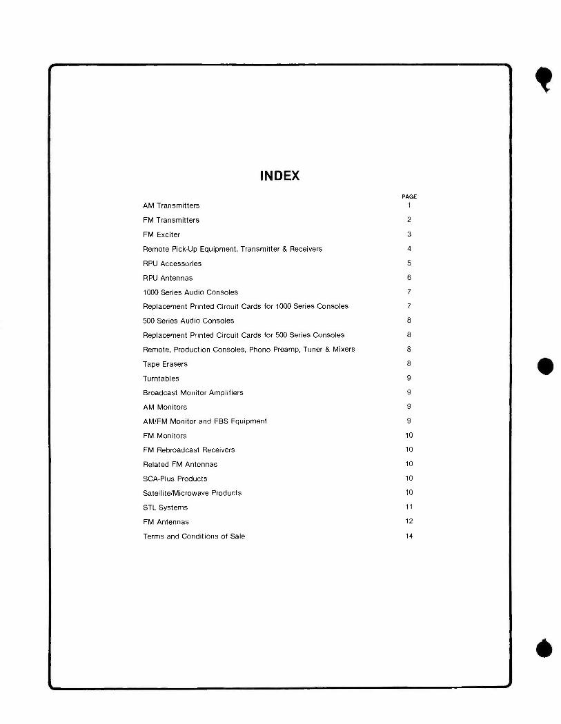
INDEX
PAGE
AM Transmitters 1
FM Transmitters 2
FM Exciter 3
Remote Pick -Up Equipment, Transmitter & Receivers 4
RPU Accessories 5
RPU Antennas 6
1000 Series Audio Consoles 7
Replacement Printed Circuit Cards for 1000 Series Consoles 7
500 Series Audio Consoles 8
Replacement Printed Circuit Cards for 500 Series Consoles 8
Mixers 8 Remote, Production Consoles, Phono Preamp, Tuner &
Tape Erasers
Turntables
Broadcast Monitor Amplifiers
AM Monitors
AM /FM Monitor and EBS Equipment
FM Monitors
FM Rebroadcast Receivers
Related FM Antennas
SCA -Plus Products
Satellite /Microwave Products
STL Systems
FM Antennas
Terms and Conditions of Sale
8
9
9
9
9
10
10
10
10
10
11
12
14
c
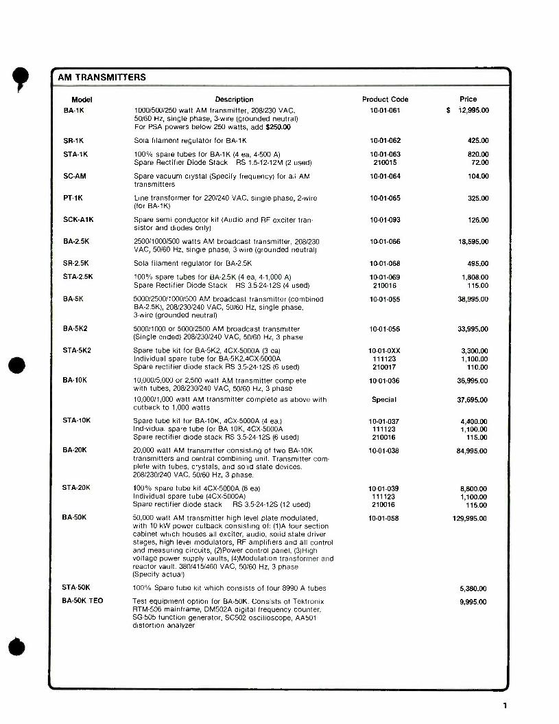
AM TRANSMITTERS
Model Description Product Code Price
BA-1K 1000/500/250 watt AM transmitter, 208/230 VAC, 50/60 Hz, single phase, 3 -wire (grounded neutral)
10 -01 -061 $ 12,995.00
For PSA powers below 250 watts, add $250.00
SR-1K Sola filament regulator for BA -1K 10-01-062 425.00
STA-1K 100% spare tubes for BA -1K (4 ea, 4 -500 A) 10-01-063 820.00 Spare Rectifier Diode Stack RS 1.5- 12 -12M (2 used) 210015 72.00
SC-AM Spare vacuum crystal (Specify frequency) for all AM transmitters
10-01-064 104.00
PT-1K Line transformer for 220/240 VAC, single -phase, 2 -wire 10-01-065 325.00 (for BA-1K)
SCK-A1K Spare semi conductor kit (Audio and RF exciter tran- sistor and diodes only)
10-01-093 126.00
BA -2.5K 2500/1000/500 watts AM broadcast transmitter, 208/230 10-01-066 18,595.00 VAC, 50/60 Hz, single phase, 3 -wire (grounded neutral)
SR-2.5K Sola filament regulator for BA -2.5K 10-01-068 495.00
STA -2.5K 100% spare tubes for BA -2.5K (4 ea, 4 -1,000 A) 10-01-069 1,808.00 Spare Rectifier Diode Stack RS 3.5 -24 -125 (4 used) 210016 115.00
BA -5K 5000/2500/1000/500 AM broadcast transmitter (combined 10.01.055 38,995.00 BA- 2.5K), 208/230/240 VAC, 50/60 Hz, single phase, 3 -wire (grounded neutral)
BA -5K2 5000/1000 or 5000/2500 AM broadcast transmitter 10-01-056 33,995.00 (Single ended) 208/230/240 VAC, 50/60 Hz, 3 phase
STA -5K2 Spare tube kit for BA -5K2, 4CX -5000A (3 ea) 10- 01.0XX 3,300.00 Individual spare tube for BA- 5K2,4CX -5000A 111123 1,100.00 Spare rectifier diode stack RS 3.5 -24 -125 (6 used) 210017 110.00
BA -10K 10,000/5,000 or 2,500 watt AM transmitter complete with tubes, 208/230/240 VAC, 50/60 Hz, 3 phase
10-01-036 36,995.00
10,000/1,000 watt AM transmitter complete as above with cutback to 1,000 watts
Special 37,695.00
STA -10K Spare tube kit for BA -10K, 4CX -5000A (4 ea.) 10-01-037 4,400.00 Individual spare tube for BA -10K, 4CX -5000A 111123 1,100.00 Spare rectifier diode stack RS 3.5- 24 -12S (6 used) 210016 115.00
BA -20K 20,000 watt AM transmitter consisting of two BA -10K transmitters and central combining unit. Transmitter com- plete with tubes, crystals, and solid state devices.
10-01-038 84,995.00
208/230/240 VAC, 50/60 Hz, 3 phase.
STA -20K 100% spare tube kit 4CX -5000A (8 ea) 10-01-039 8,800.00 Individual spare tube (4CX- 5000A) 111123 1,100.00 Spare rectifier diode stack RS 3.5- 24 -12S (12 used) 210016 115.00
BA -50K 50,000 watt AM transmitter high level plate modulated, with 10 kW power cutback consisting of: (1)A four section cabinet which houses all exciter, audio, solid state driver stages, high level modulators, RF amplifiers and all control and measuring circuits, (2)Power control panel, (3)High voltage power supply vaults, (4)Modulation transformer and reactor vault. 380/415/460 VAC, 50/60 Hz, 3 phase
10-01-058 129,995.00
(Specify actual)
STA -50K 100% Spare tube kit which consists of four 8990 A tubes 5,380.00
BA -50K TEO Test equipment option for BA -50K. Consists of Tektronix 9,995.00 RTM -506 mainframe, DM502A digital frequency counter, SG -505 function generator, SC502 oscilloscope, AA501 distortion analyzer
1
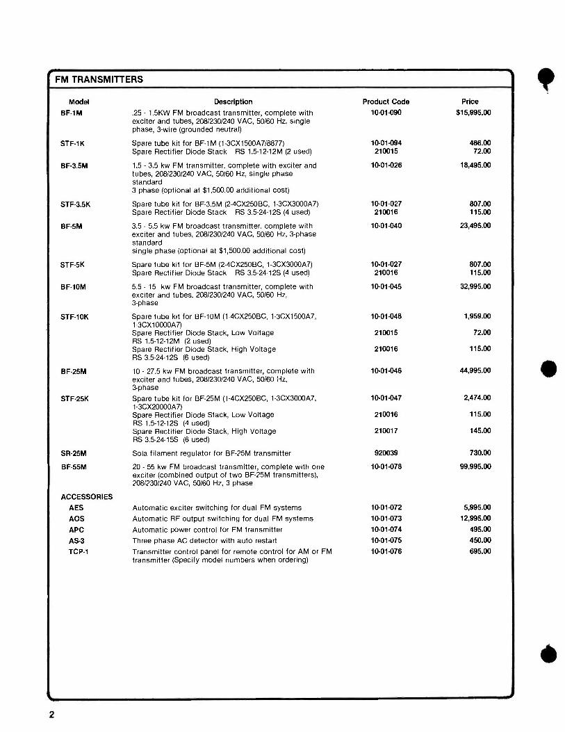
FM TRANSMITTERS
Model Description Product Code Price
BF -1M .25 - 1.5KW FM broadcast transmitter, complete with exciter and tubes, 208/230/240 VAC, 50/60 Hz, single phase, 3 -wire (grounded neutral)
10.01.090 $15,995.00
STF1K Spare tube kit for BF -1M (1- 3CX1500A7/8877) 10- 01.094 466.00 Spare Rectifier Diode Stack RS 1.5-12-12M (2 used) 210015 72.00
BF -3.5M 1.5 - 3.5 kw FM transmitter, complete with exciter and tubes, 208/230/240 VAC, 50/60 Hz, single phase standard
10.01.026 18,495.00
3 phase (optional at $1,500.00 additional cost)
STF -3.5K Spare tube kit for BF -3.5M (2- 4CX250BC, 1- 3CX3000A7) 10-01-027 807.00 Spare Rectifier Diode Stack RS 3.5- 24 -12S (4 used) 210016 115.00
BF -5M 3.5 - 5.5 kw FM broadcast transmitter, complete with exciter and tubes, 208/230/240 VAC, 50/60 Hz, 3 -phase standard single phase (optional at $1,500.00 additional cost)
10. 01.040 23,495.00
STF -5K Spare tube kit for BF -5M (2- 4CX250BC, 1- 3CX3000A7) 10. 01.027 807.00 Spare Rectifier Diode Stack RS 3.5- 24 -12S (4 used) 210016 115.00
BF -10M 5.5 - 15 kw FM broadcast transmitter, complete with exciter and tubes, 208/230/240 VAC, 50/60 Hz, 3 -phase
10- 01.045 32,995.00
STF -10K Spare tube kit for BF -10M (1- 4CX250BC, 1- 3CX1500A7, 1- 3CX10000A7)
10- 01.048 1,959.00
Spare Rectifier Diode Stack, Low Voltage 210015 72.00 RS 1.5- 12 -12M (2 used) Spare Rectifier Diode Stack, High Voltage 210016 115.00 RS 3.5 -24 -125 (6 used)
BF-25M 10 - 27.5 kw FM broadcast transmitter, complete with exciter and tubes, 208/230/240 VAC, 50/60 Hz, 3 -phase
10.01- 046 44,995.00
STF -25K Spare tube kit for BF -25M (1- 4CX250BC, 1- 3CX3000A7, 1.3CX20000A7)
10. 01.047 2,474.00
Spare Rectifier Diode Stack, Low Voltage 210016 115.00 RS 1.5- 12 -12S (4 used) Spare Rectifier Diode Stack, High Voltage 210017 145.00 RS 3.5- 24 -15S (6 used)
SR -25M Sola filament regulator for BF -25M transmitter 920039 730.00
BF -55M 20 - 55 kw FM broadcast transmitter, complete with one exciter (combined output of two BF -25M transmitters), 208/230/240 VAC, 50/60 Hz, 3 phase
10-01-078 99,995.00
ACCESSORIES
AES Automatic exciter switching for dual FM systems 10-01-072 5,995.00
AOS Automatic RF output switching for dual FM systems 10. 01.073 12,995.00
APC Automatic power control for FM transmitter 10-01-074 495.00
AS -3 Three phase AC detector with auto restart 10-01-075 450.00
TCP -1 Transmitter control panel for remote control for AM or FM transmitter (Specify model numbers when ordering)
10-01-076 695.00
2
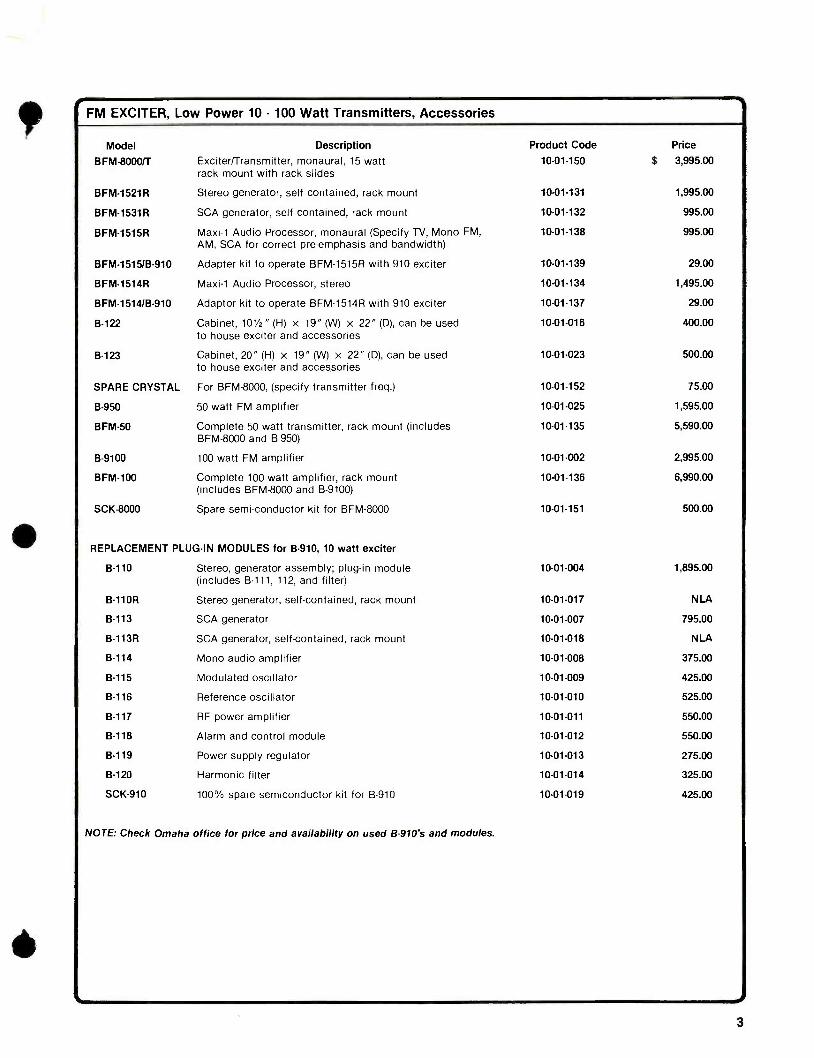
t FM EXCITER, Low Power 10 - 100 Watt Transmitters, Accessories
Model Description Product Code Price
BFM -8000íT Exciter/Transmitter, monaural, 15 watt rack mount with rack slides
10-01-150 $ 3,995.00
BFM -1521 R Stereo generator, self contained, rack mount 10.01.131 1,995.00
BFM -1531R SCA generator, self contained, rack mount 10-01-132 995.00
BFM -1515R Maxi -1 Audio Processor, monaural (Specify TV, Mono FM, AM, SCA for correct pre- emphasis and bandwidth)
10-01-138 995.00
BFM- 1515/B -910 Adapter kit to operate BFM -1515R with 910 exciter 10-01-139 29.00
BFM -1514R Maxi -1 Audio Processor, stereo 10- 01.134 1,495.00
BFM- 1514/B.910 Adaptor kit to operate BFM -1514R with 910 exciter 10-01-137 29.00
B -122 Cabinet, 101/2" (H) x 19" (W) x 22" (D), can be used to house exciter and accessories
10-01-016 400.00
B -123 Cabinet, 20" (H) x 19" (W) x 22" (D), can be used to house exciter and accessories
10.01.023 500.00
SPARE CRYSTAL For BFM -8000, (specify transmitter freq.) 10-01-152 75.00
B -950 50 watt FM amplifier 10- 01.025 1,595.00
BFM -50 Complete 50 watt transmitter, rack mount (includes 10-01-135 5,590.00
BFM -8000 and B -950)
B-9100 100 watt FM amplifier 10.01 -002 2,995.00
BFM -100 Complete 100 watt amplifier, rack mount 10-01-136 6,990.00
(includes BFM -8000 and B -9100)
SCK-8000 Spare semi -conductor kit for BFM -8000 10-01-151 500.00
REPLACEMENT PLUG -IN MODULES for B -910, 10 watt exciter
B -110 Stereo, generator assembly; plug -in module 10 -01 -004 1,895.00
(includes B -111, 112, and filter)
B -110R Stereo generator, self- contained, rack mount 10-01-017 NLA
B -113 SCA generator 10-01-007 795.00
B -113R SCA generator, self- contained, rack mount 10-01-018 NLA
B -114 Mono audio amplifier 10-01-008 375.00
B -115 Modulated oscillator 10.01.009 425.00
B -116 Reference oscillator 10-01-010 525.00
B -117 RF power amplifier 10.01.011 550.00
B -118 Alarm and control module 10-01-012 550.00
B -119 Power supply regulator 10.01 -013 275.00
B -120 Harmonic filter 10-01-014 325.00
SCK -910 100% spare semiconductor kit for B -910 10-01-019 425.00
NOTE: Check Omaha office for price and availability on used 8.910's and modules.
3
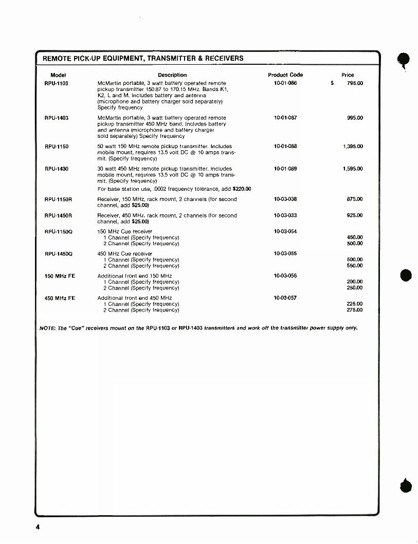
REMOTE PICK -UP EQUIPMENT, TRANSMITTER & RECEIVERS
Model Description Product Code Price
RPU -1103 McMartin portable, 3 watt battery operated remote pickup transmitter 150.87 to 170.15 MHz. Bands K1, K2, L and M. Includes battery and antenna
10-01-086 $ 795.00
(microphone and battery charger sold separately) Specify frequency
RPU -1403 McMartin portable, 3 watt battery operated remote pickup transmitter 450 MHz band. Includes battery and antenna (microphone and battery charger sold separately) Specify frequency
10-01-087 995.00
RPU -1150 50 watt 150 MHz remote pickup transmitter. Includes mobile mount, requires 13.5 volt DC @ 10 amps trans- mit. (Specify frequency)
10-01-088 1,395.00
RPU -1430 30 watt 450 MHz remote pickup transmitter. Includes mobile mount, requires 13.5 volt DC @ 10 amps trans- mit. (Specify frequency)
10-01-089 1,595.00
For base station use, .0002 frequency tolerance, add $220.00
RPU -1150R Receiver, 150 MHz, rack mount, 2 channels (for second channel, add $25.00)
10-03-038 875.00
RPU -1450R Receiver, 450 MHz, rack mount, 2 channels (for second channel, add $25.00)
10.03 -033 925.00
RPU -11500 150 MHz Cue receiver 10-03-054 1 Channel (Specify frequency) 450.00 2 Channel (Specify frequency) 500.00
RPU -14500 450 MHz Cue receiver 10-03-055 1 Channel (Specify frequency) 500.00 2 Channel (Specify frequency) 550.00
150 MHz FE Additional front end 150 MHz 10-03-056 1 Channel (Specify frequency) 200.00 2 Channel (Specify frequency) 250.00
450 MHz FE Additional front end 450 MHz 10-03-057 1 Channel (Specify frequency) 225.00 2 Channel (Specify frequency) 275.00
NOTE: The "Cue" receivers mount on the RPU -1103 or RPU -1403 transmitters and work off the transmitter power supply only.
4
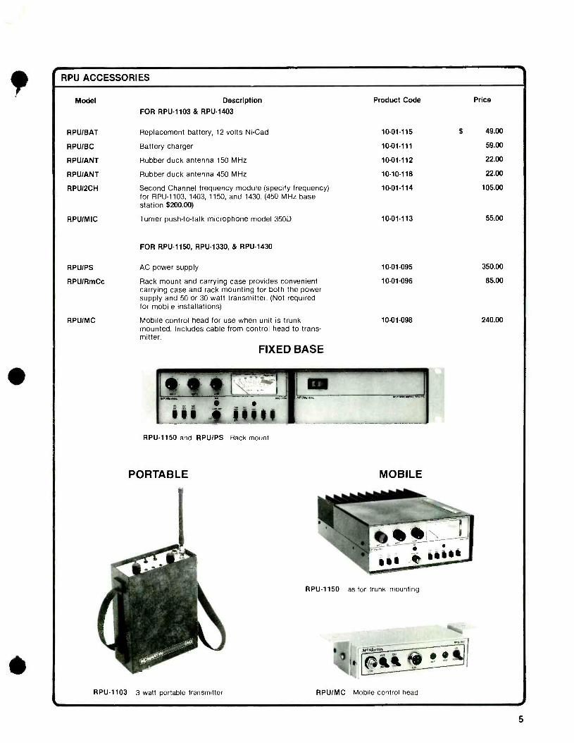
e RPU ACCESSORIES
Model Description
FOR RPU -1103 & RPU -1403
Product Code Price
RPU /BAT Replacement battery, 12 volts Ni -Cad 10.01.115 $ 49.00
RPUIBC Battery charger 10-01-111 59.00
RPU /ANT Rubber duck antenna 150 MHz 10-01-112 22.00
RPU /ANT Rubber duck antenna 450 MHz 10-10-118 22.00
RPU /2CH Second Channel frequency module (specify frequency) for RPU -1103, 1403, 1150, and 1430. (450 MHz base station $200.00)
10-01-114 105.00
RPU /MIC Turner push -to -talk microphone model 350D 10- 01.113 55.00
FOR RPU -1150, RPU -1330, & RPU -1430
RPU /PS AC power supply 10-01-095 350.00
RPU/RmCc Rack mount and carrying case provides convenient carrying case and rack mounting for both the power supply and 50 or 30 watt transmitter. (Not required for mobile installations)
10-01-096 85.00
RPU/MC Mobile control head for use when unit is trunk mounted. Includes cable from control head to trans- mitter.
10.01.098 240.00
FIXED BASE
RPU -1150 and RPU /PS Rack mount
PORTABLE
RPU -1103 3 watt portable transmitter
MOBILE
RPU -1150 as for trunk mounting
RPU /MC Mobile control head I 5
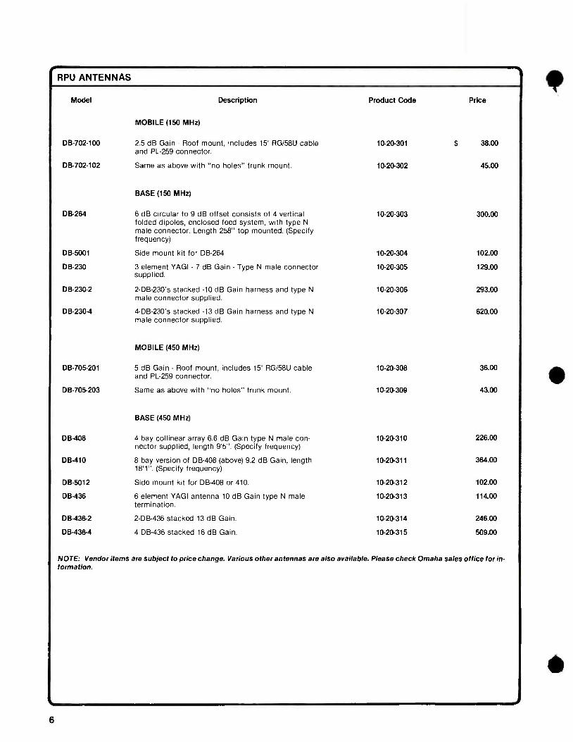
RPU ANTENNAS
Model Description
MOBILE (150 MHz)
Product Code Price
DB- 702.100 2.5 dB Gain - Roof mount, includes 15' RG /58U cable and PL -259 connector.
10.20.301 $ 38.00
DB-702-102 Same as above with "no holes" trunk mount. 10-20-302 45.00
BASE (150 MHz)
DB -264 6 dB circular to 9 dB offset consists of 4 vertical folded dipoles, enclosed feed system, with type N
male connector. Length 258" top mounted. (Specify frequency)
10-20-303 300.00
DB -5001 Side mount kit for DB -264 10-20-304 102.00
DB -230 3 element VAGI - 7 dB Gain - Type N male connector supplied.
10-20-305 129.00
DB-230-2 2- DB -230's stacked -10 dB Gain harness and type N
male connector supplied. 10 -20- 306 293.00
DB-230-4 4- DB -230's stacked -13 dB Gain harness and type N male connector supplied.
10-20-307 620.00
MOBILE (450 MHz)
DB-705-201 5 dB Gain - Roof mount, includes 15' RG /58U cable and PL -259 connector.
10-20-308 36.00
DB- 705 -203 Same as above with no holes" trunk mount. 10-20-309 43.00
BASE (450 MHz)
DB -408 4 bay collinear array 6.6 dB Gain type N male con- nector supplied, length 9'5 ". (Specify frequency)
10-20-310 226.00
DB -410 8 bay version of DB -408 (above) 9.2 dB Gain, length 10-20-311 364.00 18'1 ". (Specify frequency)
DB -5012 Side mount kit for DB -408 or 410. 10-20-312 102.00
DB -436 6 element YAGI antenna 10 dB Gain type N male termination.
10-20-313 114.00
DB -436 -2 2 -DB -436 stacked 13 dB Gain. 10-20-314 246.00
DB-436-4 4 DB -436 stacked 16 dB Gain. 10-20-315 509.00
NOTE: Vendor items are subject to price change. Various other antennas are also available. Please check Omaha sales office for in- formation.
6
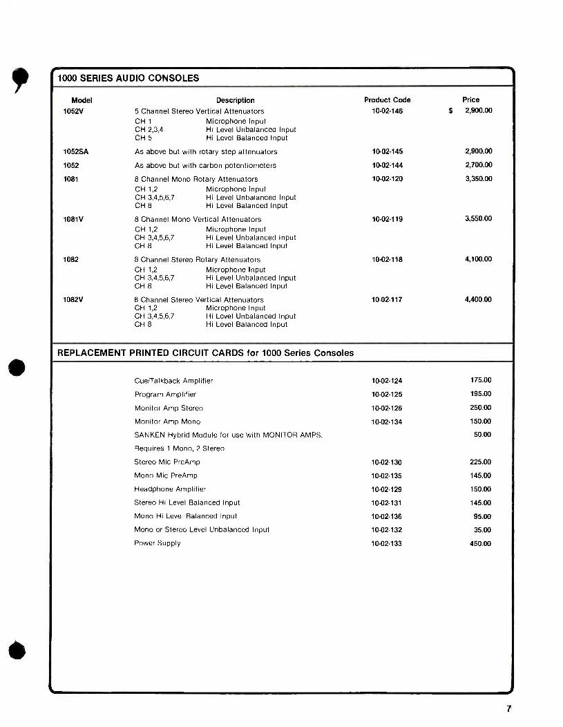
} r 1000 SERIES AUDIO CONSOLES
1
Model Description Product Code Price
1052V 5 Channel Stereo Vertical Attenuators 10-02-146 $ 2,900.00
CH 1 Microphone Input CH 2,3,4 Hi Level Unbalanced Input CH 5 Hi Level Balanced Input
1052SA As above but with rotary step attenuators 10-02-145 2,900.00
1052 As above but with carbon potentiometers 10-02-144 2,700.00
1081 8 Channel Mono Rotaiy Attenuators 10-02-120 3,350.00
CH 1,2 CH 3,4,5,6,7 CH 8
Microphone Input Hi Level Unbalanced Input Hi Level Balanced Input
1081V 8 Channel Mono Vertical Attenuators 10-02-119 3,550.00
CH 1,2 Microphone Input CH 3,4,5,6,7 Hi Level Unbalanced Input CH 8 Hi Level Balanced Input
1082 8 Channel Stereo Rotary Attenuators 10-02-118 4,100.00
CH 1,2 CH 3,4,5,6,7 CH 8
Microphone Input Hi Level Unbalanced Input Hi Level Balanced Input
1082V 8 Channel Stereo Vertical Attenuators 10.02.117 4,400.00 CH 1,2 Microphone Input CH 3,4,5,6,7 Hi Level Unbalanced Input CH 8 Hi Level Balanced Input
REPLACEMENT PRINTED CIRCUIT CARDS for 1000 Series Consoles
Cue/Talkback Amplifier 10-02-124 175.00
Program Amplifier 10-02-125 195.00
Monitor Amp Stereo 10-02-126 250.00
Monitor Amp Mono 10-02-134 150.00
SANKEN Hybrid Module for use with MONITOR AMPS. 50.00
Requires 1 Mono, 2 Stereo
Stereo Mic PreAmp 10-02-130 225.00
Mono Mic PreAmp 10-02-135 145.00
Headphone Amplifier 10-02-129 150.00
Stereo Hi Level Balanced Input 10-02-131 145.00
Mono Hi Level Balanced Input 10-02-136 95.00
Mono or Stereo Level Unbalanced Input 10-02-132 35.00
Power Supply 10-02-133 450.00
7
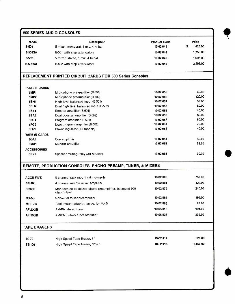
e 500 SERIES AUDIO CONSOLES
Model Description Product Code Price
B501 5 mixer, monaural, 1 mic, 4 hi -bal 10. 02.041 $ 1,425.00
B501SA B -501 with step attenuators 10.02.044 1,750.00
B502 5 mixer, stereo, 1 mic, 4 hi -bal 10-02-042 1,995.00
B -502SA B -502 with step attenuators 10-02-045 2,495.00
REPLACEMENT PRINTED CIRCUIT CARDS FOR 500 Series Consoles
PLUG-IN CARDS
5MP1 Microphone preamplifier (B -501) 10-02-056 60.00
5MP2 Microphone preamplifier (B -502) 10-02-060 120.00
5BH1 High level balanced input (B -501) 10.02.054 50.00
5BH2 Dual high level balanced input (B -502) 10-02-058 80.00
5BA1 Booster amplifier (B -501) 10-02-055 40.00
5BA2 Dual booster amplifier (B -502) 10.02.059 60.00
5PG1 Program amplifier (B -501) 10.02.057 50.00
5PG2 Dual program amplifier (B -502) 10-02-061 70.00
5PS1 Power regulator (All models) 10. 02.053 40.00
WIRE -IN CARDS
50A1 Cue amplifier 10- 02.051 55.00
5MA1 Monitor amplifier 10-02-052 75.00
ACCESSORIES
5RY1 Speaker muting relay (All Models) 10-02-064 30.00
REMOTE, PRODUCTION CONSOLES, PHONO PREAMP, TUNER, & MIXERS
ACCU-FIVE 5 channel rack mount mini console 10-02-080 752.00
BR -400 4 channel remote mixer amplifier 10-02-081 425.00
B -2008 Mono /stereo equalized phono preamplifier, balanced 600 10-02-076 ohm output
240.00
MX -5B 5- channel mixer /preamplifier 10-02-084 199.00
MRP7B Rack mount adaptor, beige, for MX -5 10-02-085 20.00
AF -200 /B AM /FM stereo tuner 10-05-018 194.00
AF -300 /B AM /FM Stereo tuner amplifier 10-05-023 309.00
TAPE ERASERS
TE -70 High Speed Tape Eraser, 7" 10.02.114 825.00
TE -105 High Speed Tape Eraser, 101/2" 10-02-115 1,150.00
i 8
t
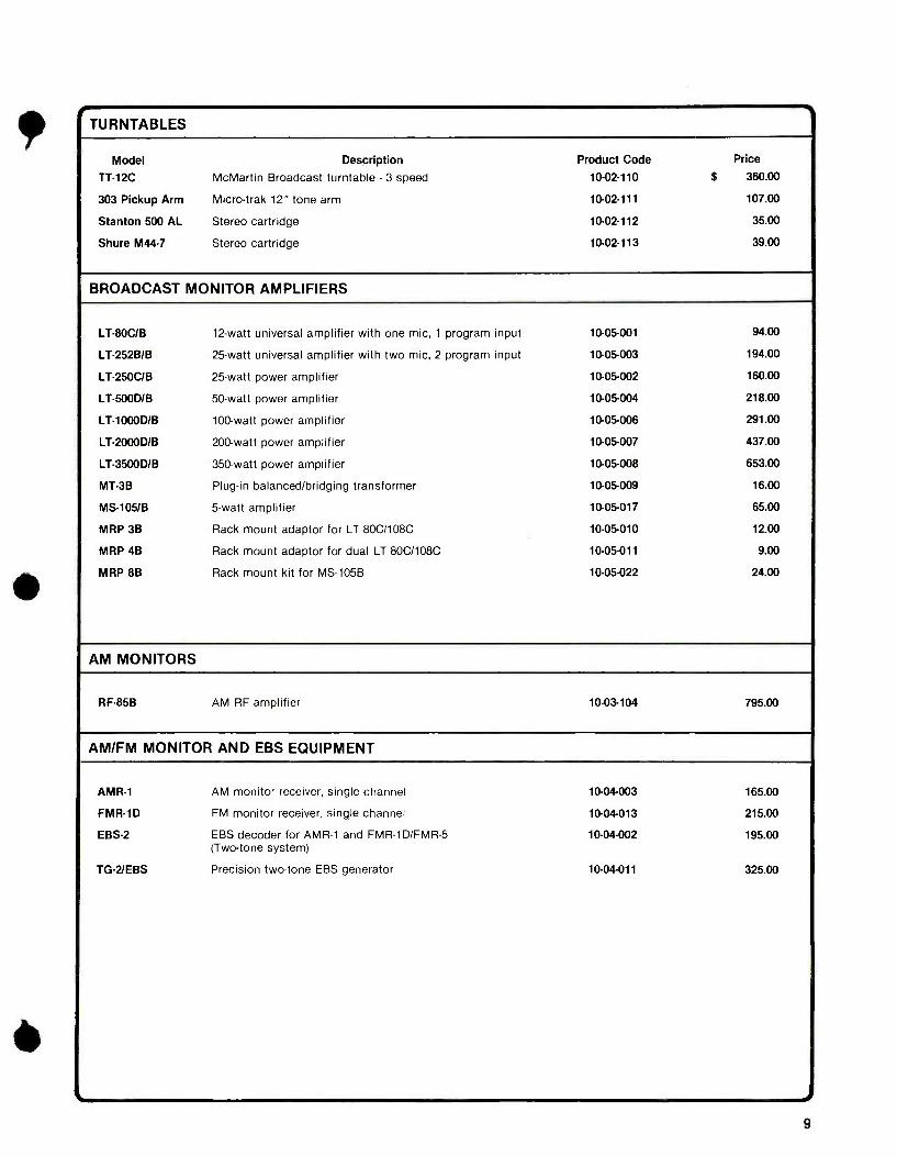
1 TURNTABLES 1
Model Description Product Code Price
TT -12C McMartin Broadcast turntable - 3 speed 10-02-110 $ 360.00
303 Pickup Arm Micro -trak 12" tone arm 10-02-111 107.00
Stanton 500 AL Stereo cartridge 10- 02.112 35.00
Shure M44 -7 Stereo cartridge 10 -02 -113 39.00
BROADCAST MONITOR AMPLIFIERS
LT -80C /B 12 -watt universal amplifier with one mic, 1 program input 10-05-001 94.00
LT252B /B 25 -watt universal amplifier with two mic, 2 program input 10-05-003 194.00
LT250C /B 25 -watt power amplifier 10.05 -002 160.00
LT500D /B 50 -watt power amplifier 10.05.004 218.00
LT1000D /B 100 -watt power amplifier 10.05.006 291.00
LT- 2000D /B 200 -watt power amplifier 10.05.007 437.00
LT- 3500D /B 350 -watt power amplifier 10-05-008 653.00
MT -3B Plug -in balanced /bridging transformer 10-05-009 16.00
MS -105 /B 5 -watt amplifier 10-05-017 65.00
MRP 3B Rack mount adaptor for LT 80C/108C 10-05-010 12.00
MRP 4B Rack mount adaptor for dual LT 80C/108C 10-05-011 9.00
MRP 8B Rack mount kit for MS -105B 10-05-022 24.00
AM MONITORS
RF -85B AM RF amplifier 10 -03 -104 795.00
AM /FM MONITOR AND EBS EQUIPMENT
AMR -1 AM monitor receiver, single channel 10-04-003 165.00
FMR -1D FM monitor receiver, single channel 10 -04 -013 215.00
EBS -2 EBS decoder for AMR -1 and FMR- 1D /FMR -5 10-04-002 195.00 (Two -tone system)
TG-2/EBS Precision two -tone EBS generator 10.04.011 325.00
9

FM MONITORS
Model Description Product Code Price
TBM -3700 Frequency and monaural modulation monitor 10.03.049 $ 2,350.00 RM -37T Remote metering plug -in card 10-03-052 150.00 RM -37R Remote metering rack mount panel 10.03.051 375.00
TBM -3500B Modulation monitor 10-03-043 1,895.00 RM -35B Remote metering rack mount panel 10.03.045 250.00 LL -35B Low level input module 10-03-044 350.00
TBM -2200A Stereo modulation and pilot frequency adaptor 10-03-034 1,795.00 (Requires TBM -3700 or TBM -3500)
RM -22T Remote metering plug -in card 10.03 -037 150.00 RM -22R Remote metering rack mount panel 10.03.036 450.00
TBM2000B SCA modulation and frequency adaptor 10.03.027 1,795.00 (Requires TBM -3700 or TBM -3500)
RM -20T Remote metering plug -in card 10. 03.030 150.00 RM -20R Remote metering rack mount panel 10.03.029 350.00
TBM2500C RF amplifier 10.03.041 750.00
FM REBROADCAST RECEIVERS
TBM1005D Five channel relay receiver (88 -108 MHz) with one crystal.
10.03.015 595.00
Each additional channel crystal 20.00
TBM -1003D Aural TV channel 2 -13 receiver 750.00
STE -1D Plug -in stereo demod card for relay receiver 10-03-012 240.00
SCA -2D Plug -in SCA demodulator card 41 kHz 10-03-010 165.00 67 kHz 10.03.011 165.00
TVR1 TV /SCA receiver, 39.5/67 kHz 40. 02.013 158.00
TR -E7 TV /SCA receiver, 39.5/67 kHz 40-02-010 150.00
TX- 200D /B FM /SCA Field strength meter (less batteries) 40.02.040 450.00
TX -200 XFMR AC Transformer for TX- 200D /B for operation of built -in battery charger
900075 10.00
RELATED FM ANTENNAS
A-72-SF-3 3 element Yagi Antenna cut to band (2 per carton) 20-03-001 20.00
A- 72 -SF -5 5 element Yagi Antenna cut to band 20 -03 -002 35.00
AS -1 Stacking harness (for A- 72- SF- 3 /SF -5) 20.03 -003 31.00
SPA2 -B Preamp /Attenuator 10.05.024 49.00
PS -13 /B Power Supply 10-05-025 49.00
SCA -Plus PRODUCTS
BSP- 28001B Dual channel SCA encoder 10. 05.026 547.00
SPH- 2800A/B Data channel decoding filter board 10-05-027 29.00
SPH- 28005/B Data channel decoding filter - stand alone model 10-05-028 44.00
SPL- 2800A/B Audio channel decoding filter board 10 -05 -029 14.00
SPL- 2800B /B Audio channel decoding filter - stand alone model 10-05-030 44.00
SATELLITE/MICROWAVE PRODUCTS
SDR -1 1B IF Demodulator 10-05-031 650.00
SMR -1/B IF Modulator 10-05-032 1,150.00
0
10
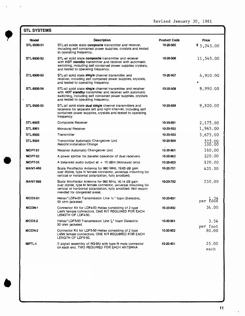
Revised January 30, 1981
STL SYSTEMS
Model Description Product Code Price
STL9500.51 STL -all solide state composite transmitter and receiver, 10- 20-505 $5,245.00 including self contained power supplies, crystals and tested to operating frequency.
STL9500 -52 STL -all solid state composite transmitter and receiver 10-20-506 11,545.00 with HOT standby transmitter and receiver with automatic switching, including self contained power supplies crystals, and tested to operating frequency.
STL9500.53 STL -all solid state single channel transmitter and 10-20-507 4,910.00 receiver, including self contained power supplies, crystals, and tested to operating frequency.
STL-9500-54 STL -all solid state single channel transmitter and receiver 10- 20-508 9,990.00 with HOT standby transmitter and receiver with automatic switching, including self contained power supplies, crystals and tested to operating frequency.
STL-9500-55 STL -all solid state dual single channel transmitters and 10. 20-509 9,820.00 receivers for separate left and right channel, including self contained power supplies, crystals and tested to operating frequency.
STL9503 Composite Receiver 10. 20.501 2,175.00
STL5901 Monaural Receiver 10- 20.502 1,965.00
STL -9500 Transmitter 10.20.503 3,675.00
STL -9504 Transmitter Automatic Changeover Unit 10.20.504 525.00 Retrofit Installation Charge 100 .00
MOPT -01 Receiver Automatic Changeover Unit 10-20-601 160.00
MOPT -02 A power splitter for parallel operation of dual receivers 10. 20-602 220.00
MOPT -03 A balanced audio output at + 10 dBm (Monaural only) 10-20-603 120.00
MANT -450 Scala Paraflector Antenna for 960 MHz, 19.65 dB gain 10. 20-701 435.00 over dipole, type N female connector, universal mounting for vertical or horizontal polarization, fully anodized.
MANT -960 Scala Miniflector Antenna for 960 MHz, 16.14 dB gain 10. 20.702 250.00 over dipole, type N female connector, universal mounting for vertical or horizontal polarization, fully anodized. Not recom- mended for congested areas.
MCOX01 Heliax' LDF4 -50 Transmission Line '/2 " foam Dielectric, 10-20-801 3 50 ohm jacketed. per oo
MCON1 Connector Kit for LDF4 -50 Heliax consisting of 2 type 10-20-802 34.00 L44N female connectors. ONE KIT REQUIRED FOR EACH LENGTH OF LDF4 -50.
MCOX -2 Heliax'LDF5 -50 Transmission Line' /8" foam Dielectric 10-20-901 3.54 50 ohm jacketed per foot
MCON -2 Connector Kit for LDF5 -50 Heliax consisting of 2 type 10- 20-902 80.00 L45N female connectors. ONE KIT REQUIRED FOR EACH LENGTH OF LDF5 -50.
MPTL -1 3' pigtail assembly of RG-8 /U with type N male connector 10-20-401 25.00 on each end. TWO REQUIRED FOR EACH ANTENNA each
11
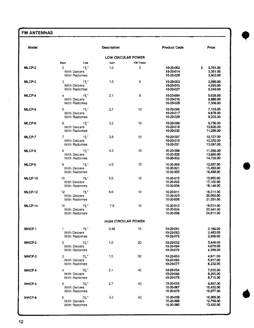
r FM ANTENNAS
Model
Bays Line
Description
LOW CIRCULAR POWER
Gain KW Power
Product Code Price
MLCP -2 2 1 %" 1.0 5 10.20 -002 $ 2,761.00 With Deicers 10. 20.014 3.391.00 With Radomes 10-20-026 3,602.00
MLCP -3 3 15'8" 1.5 6 10. 20.003 3,980.00 With-Deicers 10-20-015 4,925.00 With Radomes 10. 20.027 5,240.00
MLCP -4 4 151e" 2.1 8 10-20-004 5,628.00 With Deicers 10.20.016 6,888.00 With Radomes 10-20-028 7,308.00
MLCP -5 5 15i," 2.7 10 10-20-005 7,103.00 With Deicers 10-20-017 8.678.00 With Radomes 10-20-029 9,203.00
MLCP -6 6 1 B" 3.2 10 10-20-006 8,736.00 With Deicers 10-20-018 10,626.00 With Radomes 10-20-030 11,256.00
MLCP -7 7 1 %" 3.8 10 10-20-007 10,127.00 With Deicers 10-20-019 12,332.00 With Radomes 10-20-031 13,067.00
MLCP -8 8 18" 4.3 10 10-20-008 11,366.00 With Deicers 10-20-020 13,886.00 With Radomes 10 -20-032 14,726.00
MLCP -9 9 1 %" 4.9 10 10-20-009 12,657.00 With Deicers 10-20-021 15,493.00 With Radomes 10-20-033 16,438.00
MLCP -10 10 1,'8" 5.5 10 10- 20-010 13,950.00 With Deicers 10-20-022 17,100.00 With Radomes 10-20-034 18,149.00
MLCP -12 12 15'," 6.6 10 10-20-011 16,311.00 With Deicers 10 -20 -023 20,09Z00 With Radomes 10-20-035 21,351.00
MLCP -14 14 1518" 7.8 10 10- 20-012 19,031.00 With Deicers 10-20-024 23,441.00 With Radomes 10-20-036 24,911.00
HIGH CIRCULAR POWER
MHCP -1 1 15,8" 0.46 10 10 -20 -051 2,168.00 With Deicers 10-20-063 2,4.83.00 With Radomes 10-20-075 2,588.00
MHCP -2 2 3',B" 1.0 20 10-20-052 3,449.00 With Deicers 10-20-064 4,079.00 With Radomes 10 -20 -076 4.289.00
MHCP -3 3 378" 1.5 30 10-20-053 4,971.00 With Deicers 10-20-065 5,917.00 With Radomes 10-20-077 6,232.00
MHCP -4 4 31/8" 2.1 40 10-20-054 7,035.00 With Deicers 10 -20 -066 8,295.00 With Radomes 10-20-078 8,715.00
MHCP -5 5 3'é" 2.7 40 10-20-055 8,867.00 With Deicers 10-20-067 10.452.00 With Radomes 10-20-079 10,977.00
MRCP -6 6 3'/8" 3.2 40 10-20-056 10,909.00 With Deicers 10-20-068 12,799.00 With Radomes 10-20-080 13,4.30.00
12

FM ANTENNAS
Model
Bays Line
Description
HIGH CIRCULAR POWER
Gain KW Power
MHCP-7 7 3%3" 3.8 40 With Deicers With Radomes
MHCP -8 8 3' /8" 4.3 40 With Deicers With Radomes
MHCP -9 9 378" 4.9 40 With Deicers With Radomes
MHCP -10 10 3'/8" 5.5 40 With Deicers With Radomes
MHCP -12 12 3' /e" 6.6 40 With Deicers With Radomes
MHCP -14 14 3'/8" 7.8 40
Product Code Price
10-20-057 $ 12,657.00 10-20-069 14,862.00 10-20-081 15,598.00
10-20-058 14,201.00 10.20.070 16,721.00 10-20-082 17,561.00
10-20-059 15,818.00 10-20-071 18,653.00 10-20-083 19,598.00
10 -20 -060 17,430.00 10-20-072 20,580.00 10-20-084 21,630.00
10-20-061 20,423.00 10-20-073 24,166.00 10-20-085 25,426.00
10-20-062 23,787.00 With Deicers 10-20-074 28,198.00 With Radomes 10-20-086 29,668.00
SUPER HIGH CIRCULAR POWER
MSHCP -1 1 61/8" 0.48 30 10-20-201 3,037.00 With Deicers 10-20-211 3,596.00
MSHCP -2 2 6'/8" 1.0 60 10-20-202 5,465.00 With Deicers 10-20-212 6,589.00
MSHCP -3 3 6'/8" 1.6 80 10-20-203 8,132.00 With Deicers 10-20-213 9,818.00
MSHCP -4 4 678" 2.1 80 10 -20 -204 11,288.00 With Deicers 10-20-214 13,535.00
MSHCP -5 5 61/8" 2.7 80 10 -20 -205 13,655.00 With Deicers 10.20.215 16,464.00
MSHCP -6 6 6'/8" 3.3 80 10-20-206 16,20t00 With Deicers 10- 20.216 19,572.00
MSHCP -7 7 6y8" 3.9 80 10-20-207 18,874.00 With Deicers 10-20-217 22,806.00
MSHCP -8 8 6' /8" 4.5 80 10-20-208 20,874.00 With Deicers 10-20-218 25,368.00
MSHCP -10 10 61/8" 5.7 80 10-20-209 26,093.00 With Deicers 10-20-219 31,710.00
MSrICP -12 12 6'/8" 6.7 80 10-20-210 27,909.00 With Deicers 10-20-220 34,650.00
OPTIONS AND ACCESSORIES
Pattern measurement service Tower mount 2,000.00 Pole Mount 1,500.00
Beam tilt any amount, any antenna 750.00
Null fill any percentage, any antenna 750.00
Combined beam tilt and null fill 1,250.00
Deicer control - 2 temperature (1 -5 bays) 450.00
Deicer control - 2 temperature (6 or more bays) 600.00
Deicer control - 1 temperature for MLCP antennas 250.00
13
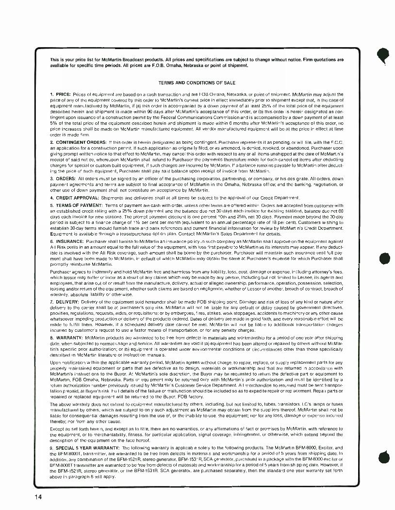
This is your price list for McMartin Broadcast products. All prices and specifications are subject to change without notice. Firm quotations are
available for specific time periods. All prices are F.O.B. Omaha, Nebraska or point of shipment.
TERMS AND CONDITIONS OF SALE
1. PRICE: Prices of equipment are based on a cash transaction and are FOB Omaha, Nebraska, or point of shipment. McMartin may adjust the price of any of the equipment covered by this order to McMartin's current price in effect immediately prior to shipment except that, in the case of equipment manufactured by McMartin, if (a) this order is accompanied by a down payment of at least 25% of the total price of the equipment described herein and shipment is made within 90 days after McMartin's acceptance of this order, or (b) this order is herein designated as con- tingent upon issuance of a construction permit by the Federal Communications Commission and is accompanied by a down payment of at least 5% of the total price of the equipment described herein and shipment is made within 6 months after McMartin's acceptance of this order, no price increases shall be made on McMartin manufactured equipment. All vendor manufactured equipment will be at the price in effect at time order is made firm.
2. CONTINGENT ORDERS: If this order is herein designated as being contingent, Purchaser represents it as pending, or will file, with the F.C.C. an application for a construction permit. If such application as originally filed, or as amended, is denied, revoked, or abandoned, Purchaser upon giving prompt written notice to that effect to McMartin, may cancel this order with respect to any or all items unshipped at the date of McMartin's receipt of said notice, whereupon McMartin shall refund to Purchaser the payments theretofore made for such cancelled items after deducting charges for special or custom -built equipment, if such charges are incurred by McMartin. If a balance remains payable to McMartin after deduct- ing the price of such equipment, Purchaser shall pay said balance upon receipt of invoice from McMartin.
3. ORDERS: All orders must be signed by an officer of the purchasing corporation, partnership, or company, or his designate. All orders, down payment agreements and terms are subject to final acceptance of McMartin in the Omaha, Nebraska office; and the banking, negotiation, or other use of down payment shall not constitute an acceptance by McMartin.
4. CREDIT APPROVAL: Shipments and deliveries shall at all times be subject to the approval of our Credit Department.
5. TERMS OF PAYMENT: Terms of payment are cash with order, unless other terms are offered within. Orders are accepted from customer with an established credit rating with a 25% down payment and the balance due net 30 days each invoice for existing stations, balance due net 60
days each invoice for new stations. The prompt payment discount is one percent 10th and 25th, net 30 days. Payment made beyond the 30 -day period is subject to a finance charge of 11/2 per cent per month (equivalent to an annual percentage rate of 18 per cent). Customers wishing to establish 30 -day terms should furnish trade and bank references and current financial information for review by McMartin's Credit Department. Equipment is available through a lease /purchase option plan. Contact McMartin's Sales Department for details.
6. INSURANCE: Purchaser shall furnish to McMartin an insurance policy in such company as McMartin shall approve on the equipment against All Risk perils in an amount equal to the full value of the equipment, with loss first payable to McMartin as its interests may appear. If any deduct- ible is involved with the All Risk coverage, such amount shall be borne by the purchaser. Purchaser will maintain such insurance until full pay- ment shall have been made to McMartin, in default of which McMartin may obtain the same at Purchaser's expense for which Purchaser shall promptly reimburse McMartin.
Purchaser agrees to indemnify and hold McMartin free and harmless from any liability, loss, cost, damage or expense, including attorney's fees, which lessor may suffer or incur as a result of any claims which may be made by any person, including but not limited to Lessee, its agents and employees, that arise out of or result from the manufacture, delivery, actual or alleged ownership, performance, operation, possession, selection, leasing and /or return of the equipment, whether such claims are based on negligence, whether of Lessor of another, breach of contract, breach of warranty, absolute liability or otherwise.
7. DELIVERY: Delivery of the equipment sold hereunder shall be made FOB shipping point. Damage and risk of loss of any kind or nature after delivery to the carrier shall be at purchaser's sole risk. McMartin will not be liable for any default or delay caused by government directives, priorities, regulations, requests, aides, or requisitions; or by embargoes, fires, strikes, work stoppages, accidents to machinery or any other cause whatsoever impeding production or delivery of the products ordered. Dates of delivery are made in good faith, and every reasonable effort will be made to fulfill them. However, if a scheduled delivery date cannot be met, McMartin will not be liable to additional transportation charges incurred by customer's request to use a faster means of transportation, or for any penalty charges.
8. WARRANTY: McMartin products are warranted to be free from defects in materials and workmanship for a period of one year after shipping date, when subjected to normal usage and service. All warranties are void if (a) equipment has been altered or repaired by others without McMar- tin's specific prior authorization; or (b) equipment is operated under environmental conditions or circumstances other than those specifically described in McMartin literature or instruction manuals.
Upon notification within the applicable warranty period, McMartin agrees without charge, to repair, replace, or supply replacement parts for any properly maintained equipment or parts that are defective as to design, materials or workmanship and that are returned in accordance with McMartin's instructions to the Buyer. At McMartin's sole discretion, the Buyer may be requested to return the defective part or equipment to McMartin, FOB Omaha, Nebraska. Parts or equipment may be returned only with McMartin's prior authorization and must be identified by a
return authorization number previously issued by McMartin's Customer Service Department. All merchandise so returned must be sent transpor- tation prepaid, at Buyer's risk. Full details of the failure or malfunction should be included so as to expedite repair or replacement. Repair parts or repaired or replaced equipment will be returned to the Buyer, FOB factory.
The above warranty does not extend to equipment manufactured by others, including, but not limited to, tubes, transistors, I.C's lamps or fuses manufactured by others, which are subject to only such adjustment as McMartin may obtain from the suppliers thereof. McMartin shall not be
liable for consequential damages resulting from the use of, or the inability to use, the equipment; nor for any loss, damage or expense incurred thereby; nor from any other cause.
Except as set forth herein, and except as to title, there are no warranties, or any affirmations of fact or promises by McMartin, with reference to
the equipment, or to merchantability, fitness, for particular application, signal coverage, infringement, or otherwise, which extend beyond the description of the equipment on the face hereof.
9. SPECIAL 5 YEAR WARRANTY: The following warranty is applicable solely to the following products. The McMartin BFM -8000, Exciter, and
the BFM- 8000T, transmitter, are warranted to be free from defects in materials and workmanship for a period of 5 years from shipping date. In
addition, any combination of the BFM -1521 R, stereo generator, BFM- 1531R, SCA generator, purchased in a package with the BFM -8000 exciter or
BFM -8000T transmitter are warranted to be free from defects of materials and workmanship for a period of 5 years from shipping date. However, if the BFM- 1521R, stereo generator, or the BFM- 1531R, SCA generator, are purchased separately, then the standard one year warranty set forth above in paragraph 8 will apply.
14
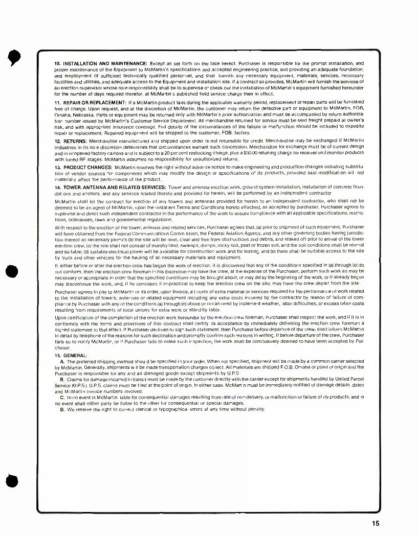
10. INSTALLATION AND MAINTENANCE: Except as set forth on the face hereof, Purchaser is responsible for the prompt installation, and proper maintenance of the Equipment to McMartin's specifications and accepted engineering practice, and providing an adequate foundation, and employment of sufficient technically qualified personnel, and shall furnish any necessary equipment, materials, services, necessary facilities and utilities, and adequate access to the Equipment and installation site. If a contract so provides, McMartin will furnish the services of an erection supervisor whose sole responsibility shall be to supervise or check out the installation of McMartin's equipment furnished hereunder for the number of days required therefor, at McMartin's published field service charge then in effect.
11. REPAIR OR REPLACEMENT: If a McMartin product faits during the applicable warranty period, replacement or repair parts will be furnished
free of charge. Upon request, and at the discretion of McMartin, the customer may return the defective part or equipment to McMartin, FOB,
Omaha, Nebraska. Parts or equipment may be returned only with McMartin's prior authorization and must be accompanied by return authoriza-
tion number issued by McMartin's Customer Service Department. All merchandise returned for service must be sent freight prepaid at owner's
risk, and with appropriate insurance coverage. Full details of the circumstances of the failure or malfunction should be included to expedite
repair or replacement. Repaired equipment will be shipped to the customer, FOB, factory.
12. RETURNS: Merchandise manufactured and shipped upon order is not returnable for credit. Merchandise may be exchanged if McMartin
Industries in its sole discretion determines that circumstances warrant such concession. Merchandise for exchange must be of current design
and in unopened factory cartons and is subject to a 20 per cent restocking charge, plus a $30.00 retuning charge for receiver and monitor products with tuned RF stages. McMartin assumes no responsibility for unauthorized returns.
13. PRODUCT CHANGES: McMartin reserves the right without advance notice to make engineering and production changes including substitu-
tion of vendor sources for components which may modify the design or specifications of its products, provided said modification will not
materially affect the performance of the product.
14. TOWER, ANTENNA AND RELATED SERVICES: Tower and antenna erection work, ground system installation, installation of concrete foun-
dations and anchors, and any services related thereto and provided for herein, will be performed by an independent contractor.
McMartin shall let the contract for erection of any towers and antennas provided for herein to an independent contractor, who shall not be
deemed to be an agent of McMartin, upon the installers Terms and Conditions hereto attached, as accepted by purchaser. Purchaser agrees to
supervise and direct such independent contractor in the performance of the work to assure compliance with all applicable specifications, restric-
tions, ordinances, laws and governmental regulations.
With respect to the erection of the tower, antenna and related services, Purchaser agrees that, (a) prior to shipment of such equipment, Purchaser will have obtained from the Federal Communications Commission, the Federal Aviation Agency, and any other governing bodies having jurisdic- tion thereof all necessary permits (b) the site will be level, clear and free from obstructions and debris, and staked off prior to arrival of the tower
erection crew, (c) the site shall not consist of marshy land, swamps, dumps, rocky soil, peat or frozen soil, and the soil conditions shall be normal
and suitable, (d) suitable electrical power will be available for construction work and for testing, and (e) there shall be suitable access to the site
by truck and other vehicles for the hauling of all necessary materials and equipment.
If, either before or after the erection crew has begun the work of erection, it is discovered that any of the conditions specified in (a) through (e) do
not conform, then the erection crew foreman in his discretion may have the crew, at the expense of the Purchaser, perform such work as may be
necessary or appropriate in order that the specified conditions may be brought about, or may delay the beginning of the work, or if already begun
may discontinue the work, and, if he considers it impractical to keep the erection crew on the site, may have the crew depart from the site.
Purchaser agrees to pay to McMartin or its order, upon invoice, all costs of extra material or services required for the performance of work related
to the installation of towers, antennas or related equipment including any extra costs incurred by the contractor by reason of failure of corn -
pliance by Purchaser with any of the conditions (a) through (e) above or occasioned by inclement weather, labor difficulties, or excess labor costs resulting from requirements of local unions for extra work or stand -by labor.
Upon certification of the completion of the erection work hereunder by the erection crew foreman, Purchaser shall inspect the work, and if it is in
conformity with the terms and provisions of this contract shall certify its acceptance by immediately delivering the erection crew foreman a
signed statement to that effect. If Purchaser declines to sign such statement, then Purchaser before departure of the crew, shall inform McMartin in detail by telephone of the reasons for such declination and promptly confirm such reasons in writing. If before departure of the crew, Purchaser
fails so to notify McMartin, or if Purchaser fails to make such inspection, the work shall be conclusively deemed to have been accepted by Pur-
chaser.
15. GENERAL: A. The preferred shipping method should be specified in your order. When not specified, shipment will be made by a common carrier selected
by McMartin. Generally, shipments will be made transportation charges collect. All materials are shipped F.O.B. Omaha or point of origin and the
Purchaser is responsible for any and all damaged goods except shipments by U.P.S.
B. Claims for damage incurred in transit must be made by the customer directly with the carrier except for shipments handled by United Parcel
Service (U.P.S.). U.P.S. claims must be filed at the point of origin. In either case, McMartin must be immediately notified of damage details, dates
and McMartin invoice numbers involved. C. In no event is McMartin liable for consequential damages resulting from late of non -delivery, or malfunction or failure of its products, and in
no event shall either party be liable to the other for consequential or special damages. D. We reserve the right to correct clerical or typographical errors at any time without penalty.
15
MCMARTIN
NOVEMBER 80 Printed in U.S.A.
a+r
."1ft.
. F
9StFITItlst[TIlitlálá>'1mgannutmo
.. i.J13.3.. .l',i71t1
4 rg k«. -II._ . 'NWItr;tátettV
,: 9011 - _ --....,;:,..t:-....:0*.....,
ALL ORDERS MUST USE PRODUCT CODE NUMBERS
ALL PRICES ARE FOB FACTORY AND SUBJECT TO CHANGE WITHOUT NOTICE
MINIMUM ORDER $15.00
McMartin Industries, Inc. 4500 South 76th Street Omaha, Nebraska 68127 Telephone (402) 331 -2000 Telex 484485
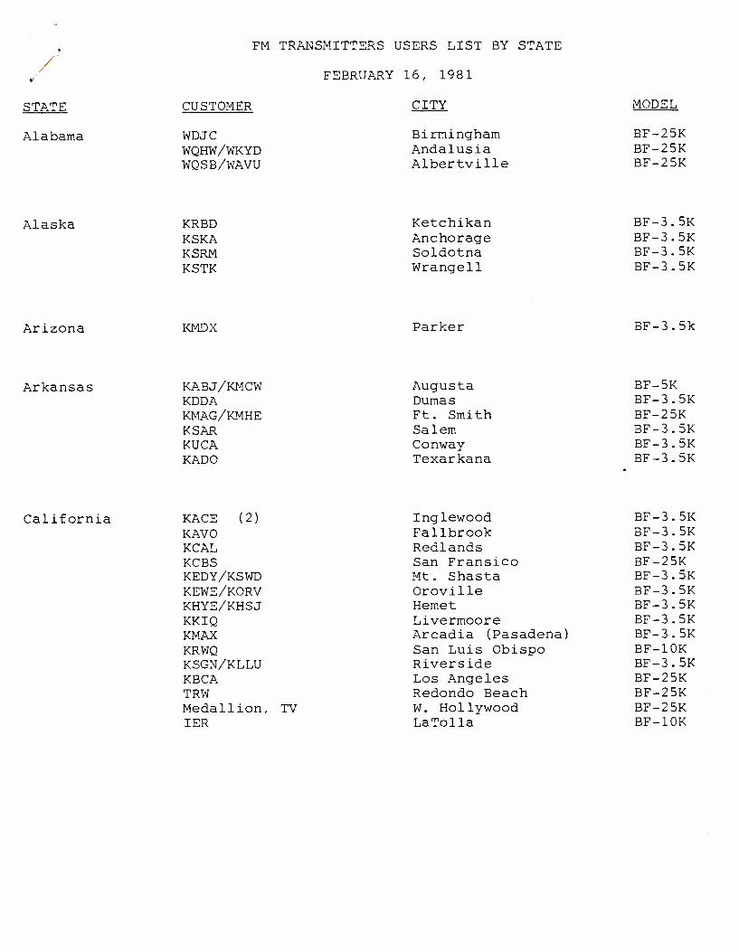
FM TRANSMITTERS USERS LIST BY STATE
FEBRUARY 16, 1981
STATE CUSTOMER CITY MODEL
Alabama WDJC Birmingham BF -25K WQHW /WKYD Andalusia BF -25K WQSB /WAVU Albertville BF -25K
Alaska KRBD Ketchikan BF-3.5K KSKA Anchorage BF-3.5K KSRM Soldotna BF-3.5K KSTK Wrangell BF-3.5K
Arizona KMDX Parker BF -3.5k
Arkansas
California
KABJ /KMCW Augusta BF -5K KDDA Dumas BF -3.5K KMAG /KMHE Ft. Smith BF -25K KSAR Salem BF -3.5K KUCA Conway BF -3.5K KADO Texarkana BF -3.5K
KACE (2) Inglewood BF -3.5K KAVO Fallbrook BF -3.5K KCAL Redlands BF -3.5K KCBS San Fransico BF -25K KEDY /KSWD Mt. Shasta BF -3.5K KEWE /KORV Oroville BF -3.5K KHYE /KHSJ Hemet BF -3.5K KKIQ Livermoore BF -3.5K KMAX Arcadia (Pasadena) BF -3.5K KRWQ San Luis Obispo BF -10K KSGN /KLLU Riverside BF -3.5K KBCA Los Angeles BF -25K TRW Redondo Beach BF -25K Medallion, TV W. Hollywood BF -25K IER LaTolla BF -10K

Colorado
Florida
Georgia
Hawaii
Idaho
Illinois
Indiana
KMTS KRAI KULE KVRH KWBI KWDE KLMR
WEAI WLYF /WGBS WMEZ WPDQ /WKUE WPFM /WWQM WQUH /WGTX WWBA Indian River Comm Lower Keys Broadcasting
WIFO WRFG Roscom
KKAI/KBCA
KGEM/KJOT KRBU
WCSJ WFIW WSPY WVJC WZOE WCCO WRUL
WJCK WBST WRIA
Glenwood Springs Craig Gunnison Salida Morrison Montrose Lemar
Jacksonville Miami Pensacola Jacksonville Panama City DeFuniak Springs St. Petersburg Fort Pierce Ft. Lauderdale
Jessup Atlanta Roswell
Kailua
Boise Pocatello
Morris Fairfield Plano Mt. Carmel Princeton Joliet Carmi
Rensslaer Muncie Richmond
BF-3.5K BF-10K BF-3.5K BF-3.5K BF-3.5K BF-25K BF-25K
BF-5K BF-25K BF-25K BF-3.5K BF-25K BF-3.5K BF-55K BF-3.5M BF-3.5M
BF-5K BF-3.5K BF-1M
BF-55K
BF-25K BF-3.5K
BF-3.5K BF-3.5K BF-5K BF-10K BF-3.5K BF-3.5M BF-10M
BF-10K BF-3.5K BF-10K
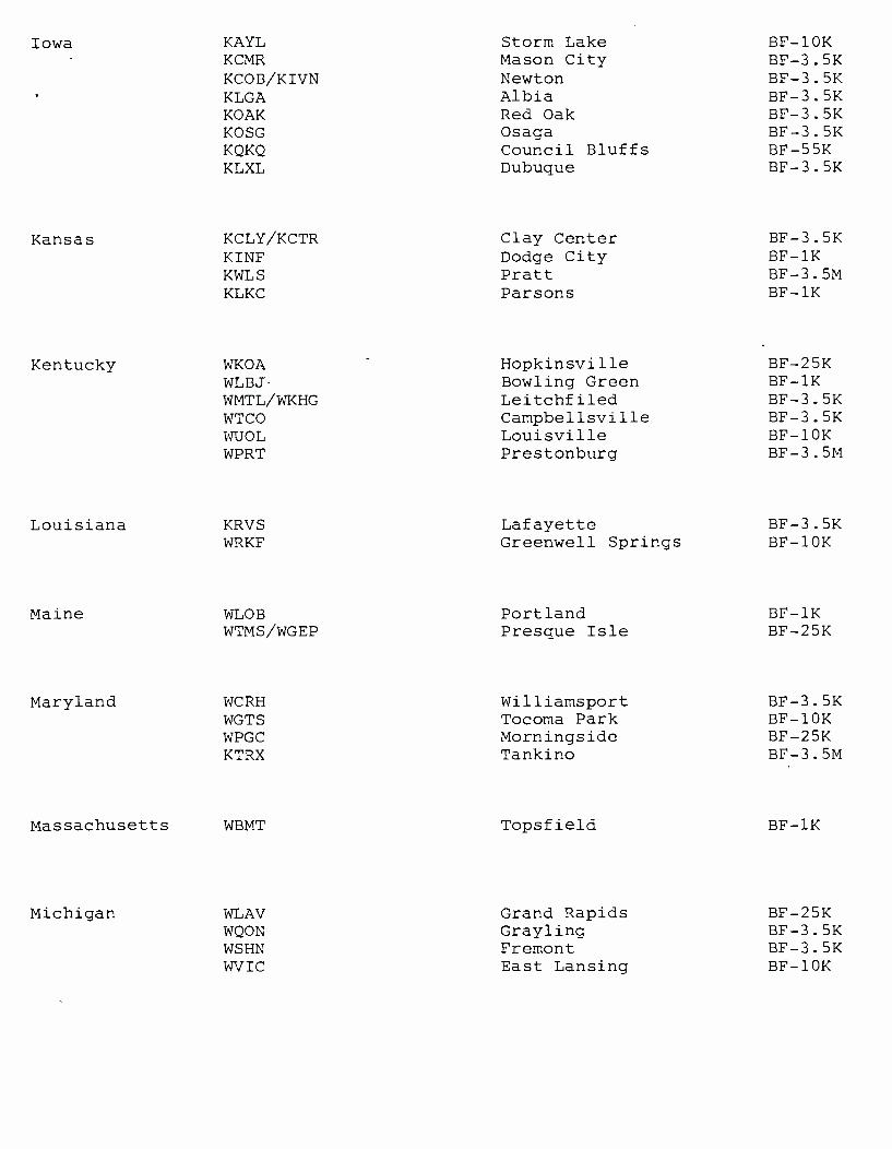
Iowa
Kansas
Kentucky
KAYL Storm Lake BF -10K KCMR Mason City BF -3.5K KCOB /KIVN Newton BF -3.5K KLGA Albia BF -3.5K KOAK Red Oak BF -3.5K KOSG Osaga BF -3.5K KQKQ Council Bluffs BF -55K KLXL Dubuque BF -3.5K
KCLY /KCTR Clay Center BF -3.5K KINF Dodge City BF -1K KWLS Pratt BF -3.5M KLKC Parsons BF -1K
WKOA Hopkinsville BF -25K WLBJ Bowling Green BF -1K WMTL /WKHG Leitchfiled BF -3.5K WTCO Campbellsville BF -3.5K WUOL Louisville BF -10K WPRT Prestonburg BF -3.5M
Louisiana KRVS Lafayette BF -3.5K WRKF Greenwell Springs BF -10K
Maine WLOB Portland BF -1K WTMS /WGEP Presque Isle BF -25K
Maryland WCRH Williamsport BF -3.5K WGTS Tocoma Park BF -10K WPGC Morningside BF -25K KTRX Tankino BF -3.5M
Massachusetts WBMT Topsfield BF -1K
Michigan WLAV Grand Rapids BF -25K WQON Grayling BF -3.5K WSHN Fremont BF -3.5K WVIC East Lansing BF -10K
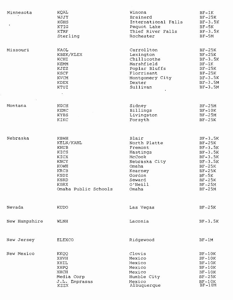
Minnesota
Missouri
Montana
Nebraska
KQAL Winona BF -1I{ WJJY Brainerd BF -25K KGHS International Falls BF -3.5K KTIG Pequot Lake BF -5K KTRF Thief River Falls BF -3.5K Sterling Rochester BF -5M
KAOL Carrollton BF -25K KBEK /KLEX Lexington BF -25K KCHI Chillicothe BF -3.5K KEMM Marshfield BF -1K KJEZ Poplar Bluffs BF -25K KSCF Florrisant BF -25K KVCM Montgomery City BF -3.5K KDEX Dexter BF -3.5M KTUI Sullivan BF -3.5M
KGCH Sidney BF -25M KEMC Billings BF -10K KYBS Livingston BF -25M KIKC Forsyth BF -25K
KBWH Blair BF -3.5K KELN /KAHL North Platte BF -25K KHUB Fremont BF -3.5K KICS Hastings BF -3.5K KICX McCook BF -3.5K KNCY Nebraska City BF -3.5K KOWH Omaha BF -25K KRCB Kearney BF -25K KSDZ Gordon BF -5K KSRD Seward BF -25K KBRX O'Neill BF -25M Omaha Public Schools Omaha BF -25M
Nevada KUDO
New Hampshire WLNH
Las Vegas
Laconia
BF-25K
BF-3.5K
New Jersey ELEXCO Ridgewood BF -1M
New Mexico KKQQ Clovis BF -10K XHVH Mexico BF -10K XHIL Mexico BF -10K XHPQ Mexico BF -10K XHCH Mexico BF -10K Media Corp Humble City BF -25K J.L. Emprasas Mexico BF -10K KZZX Albuquerque BF -10M

New York KRKT Albany BF -25K WAQX Syracuse BF -1K WCBS New York City BF -10K WDST Woodstock BF -3.5K WSUL Monticello BF -3.5K WVKR Poughkeepsie BF -1K WVOS Liberty BF -3.5K WCBC New York City BF -10K
North Carolina HYDE Swan Quarter BF -1M
North Dakota KFNW Fargo BF -25K
Ohio WBBY Westerville BF -1K WDMT Salon BF -5K WKTL Struthers BF -3.5K WKTN Kenton BF -3.5K WWWJ Johnston BF -3.5K WYPC /WJEH Gallipolis BF -25K
Oklahoma KASX ADA BF -1K KCLI Clinton BF -3.5K KGOW Tulsa BF -3.5K KNID /KCRC Enid BF -25K KPNC Ponca City BF -3.5K KTLQ Talequah BF -3.5K KOKF Edmond BF -3.5K
Oregon KRCO Pineville BF -3.5M KSBC Redmond BF -3.5M KICR Salem BF -3.5K KKIC /KEMX Ashland BF -3.5K KOHU Hermiston BF -3.5K KOKF Edmond BF -3.5K KOOS North Bend BF -1K KYNG Eastside BF -3.5K KIDO New Port BF -3.5M KBKR Baker BF -3.5M KRWQ Gold Hill BF -10K
Pennsylvannia WCUC Clarion BF -1K WGRP Greenville BF -3.5K WHYP Northeast BF -3.5K WTTC Towanda BF -3.5K WVCS California BF -3.5K
South Carolina WAIM Anderson BF -25K
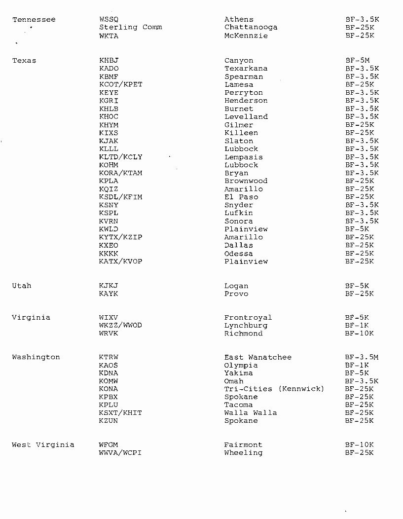
Tennessee
Texas
WSSQ Athens BF -3.5K Sterling Comm Chattanooga BF -25K WKTA McKennzie BF -25K
KHBJ Canyon BF -5M KADO Texarkana BF -3.5K KBMF Spearman BF -3.5K KCOT /KPET Lamesa BF -25K KEYE Perryton BF -3.5K KGRI Henderson BF -3.5K KHLB Burnet BF -3.5K KHOC Levelland BF -3.5K KHYM Gilmer BF -25K KIXS Killeen BF -25K KJAK Slaton BF -3.5K KLLL Lubbock BF -3.5K KLTD /KCLY Lempasis BF -3.5K KOHM Lubbock BF -3.5K KORA /KTAM Bryan BF -3.5K KPLA Brownwood BF -25K KQIZ Amarillo BF -25K KSDL /KFIM El Paso BF -25K KSNY Snyder BF -3.5K KSPL Lufkin BF-3.5K KVRN Sonora BF -3.5K KWLD Plainview BF -5K KYTX /KZIP Amarillo BF -25K KXEO Dallas BF -25K KKKK Odessa BF -25K KATX /KVOP Plainview BF -25K
Utah KJKJ Logan BF -5K KAYK Provo BF -25K
Virginia WIXV Frontroyal BF -5K WKZZ /WWOD Lynchburg BF -1K WRVK Richmond BF -10K
Washington KTRW East Wanatchee BF -3.5M KAOS Olympia BF -1K KDNA Yakima BF -5K KOMW Omah BF -3.5K KONA Tri -Cities (Kennwick) BF -25K KPBX Spokane BF -25K KPLU Tacoma BF -25K KSXT /KHIT Walla Walla BF -25K KZUN Spokane BF -25K
West Virginia WFGM Fairmont BF -10K WWVA /WCPI Wheeling BF -25K

Wisconsin WJMC Rice Lake BF -25K WORT Madison BF -3.5K WWSP Stevens Point BF -1K
Wyoming KIOZ Laramie BF -25K
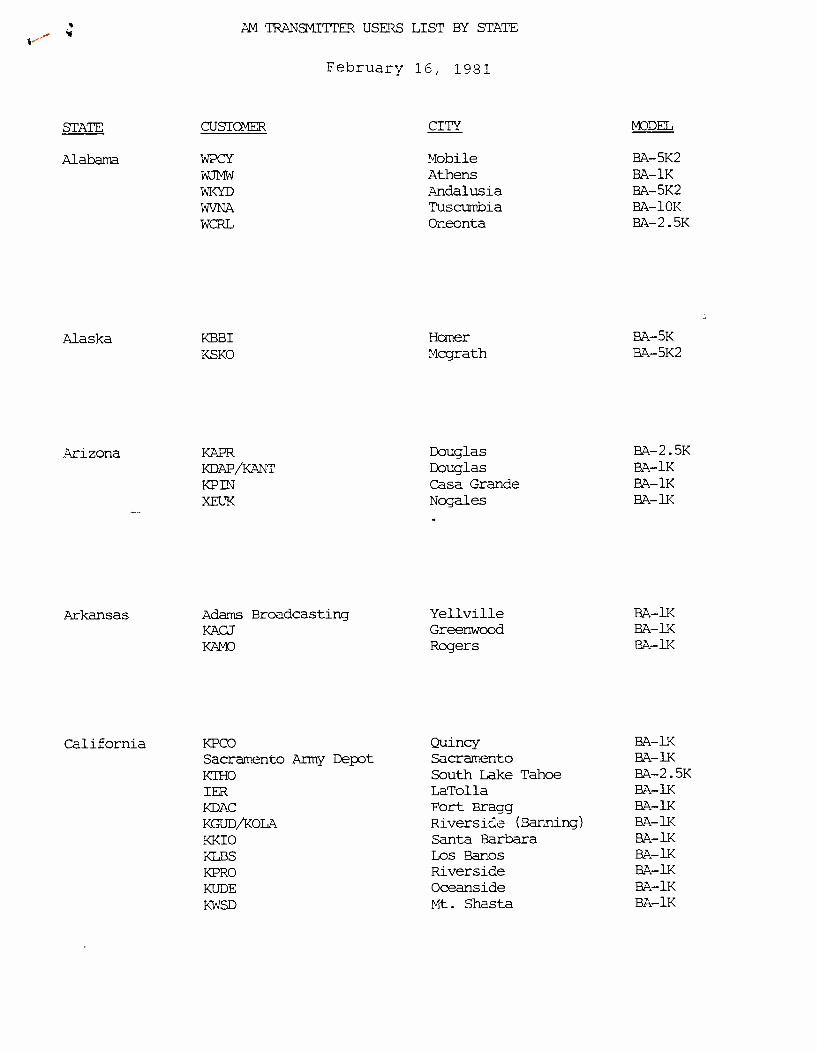
STATE
Alabama
Alaska
Arizona
Arkansas
AM TRANSMITTER USERS LIST BY STAlE
February 16, 1981
CUSS CITY MODEL
WPCY Mobile BA -5K2 WJMW Athens BA -1K WKYD Andalusia BA -5K2
WVNA Tuscurnbia BA -10K WCRL Oneonta BA -2.5K
KBBI Homer BA-5K
KSKO Mcgrath BA-5K2
KAPR Douglas BA -2.5K
KDAP /KANT Douglas BA -1K
KPIN Casa Grande BA -1K XEUK Nogales BA -1K
Adams Broadcasting Yellville BA -1K KACJ Greenwood BA -1K
KAMO Rogers 2A -1K
California KPCO Quincy BA -1K
Sacramento Army Depot Sacramento BA -1K
KTHO South Lake Tahoe BA -2.5K
IER LaTolla BA -1K
KDAC Fort Bragg BA-1K
KGUD/KOLA Riverside (Banning) BA -1K
KKIO Santa Barbara BA -1K
KIM Los Banos BA-1K
KPRO Riverside BA -1K
KUDE Oceanside BA -1K
KWSD Mt. Shasta HA-1K
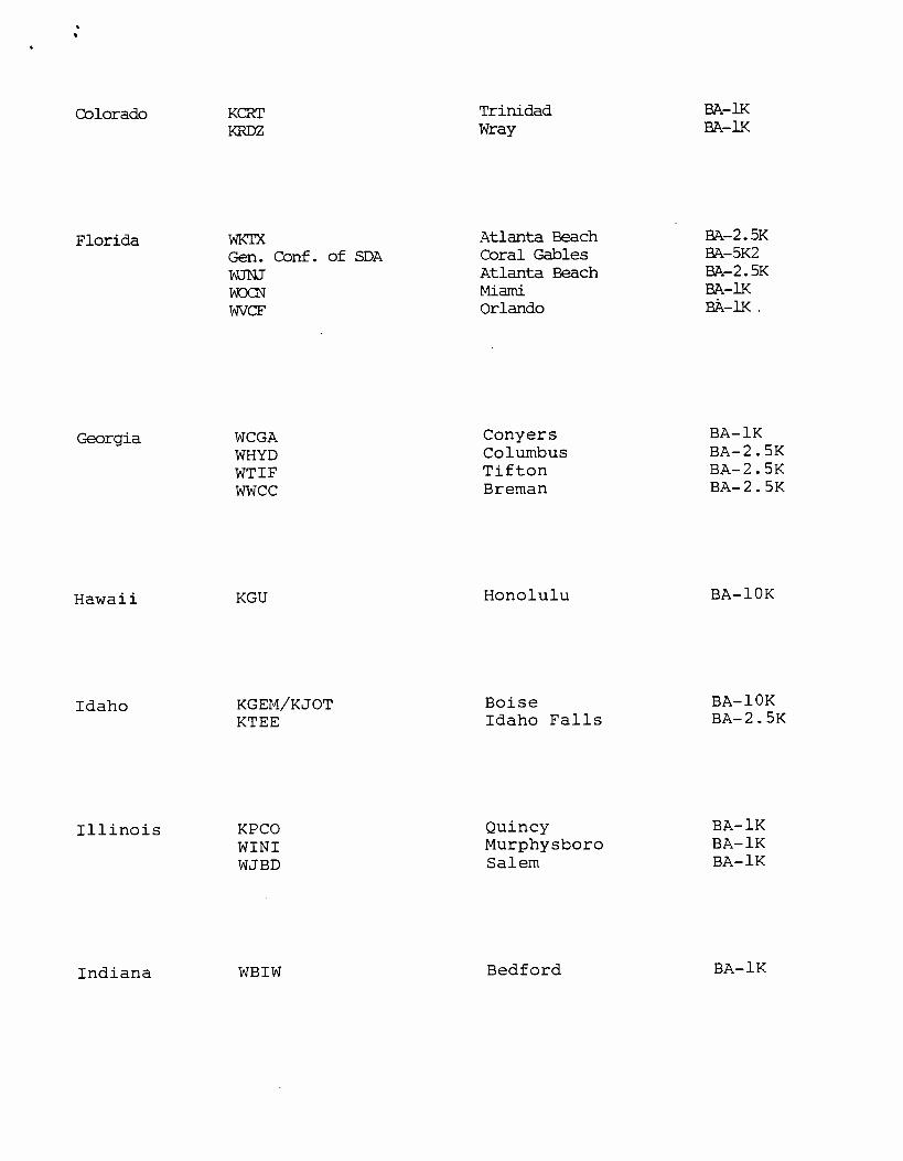
Colorado
Florida
Georgia
KCRT Trinidad BA -1K
KRDZ Wray BA 1K
WYTX Atlanta Beach BA -2.5K
Gen. Conf. of SDA Coral Gables BA-5K2
WJNJ Atlanta Beach BA -2.5K WOCN Miami BA -IK
WVCF Orlando FA-1K .
WCGA Conyers BA -1K
WHYD Columbus BA -2.5K WTIF Tifton BA -2.5K WWCC Breman BA -2.5K
Hawaii KGU Honolulu BA -10K
Idaho
Illinois
KGEM/KJOT KTEE
Boise Idaho Falls
BA-10K BA-2.5K
KPCO Quincy BA -1K WINI Murphysboro BA -1K WJBD Salem BA -1K
Indiana WBIW Bedford BA -1K
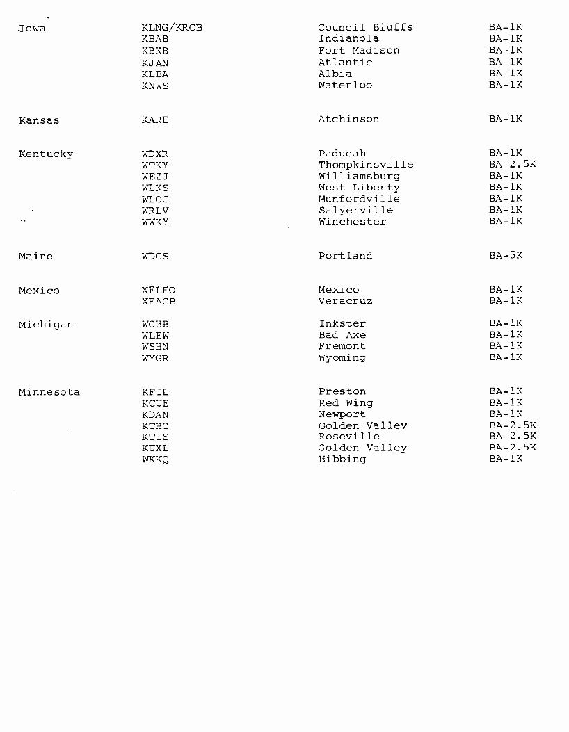
Jowa KLNG /KRCB Council Bluffs BA -1K KBAB Indianola BA -1K KBKB Fort Madison BA -1K KJAN Atlantic BA -1K KLBA Albia BA -1K KNWS Waterloo BA -1K
Kansas KARE Atchinson BA -1K
Kentucky WDXR Paducah BA -1K WTKY Thompkinsville BA -2.5K WEZJ Williamsburg BA -1K WLKS West Liberty BA -1K WLOC Munfordville BA -1K WRLV Salyerville BA -1K WWKY Winchester BA -1K
Maine WDCS Portland BA -5K
Mexico XELEO Mexico BA -1K XEACB Veracruz BA -1K
Michigan WCHB Inkster BA -1K WLEW Bad Axe BA -1K WSHN Fremont BA -1K WYGR Wyoming BA -1K
Minnesota KFIL Preston BA -1K KCUE Red Wing BA -1K KDAN Newport BA -1K KTHO Golden Valley BA -2.5K KTIS Roseville BA -2.5K KUXL Golden Valley BA -2.5K WKKQ Hibbing BA -1K

Mississippi WABG Greenwood BA -1K
Missouri
Montana
Nebraska
KBIN Neosho BA -1K KCMW Warrensburg BA -1K KXEO Mexico BA -1K
KLYC Laurel BA -lk KTXX Whitefish BA -lk
KESY Omaha BA -1K KGFW Kearney BA -1K KGMT Fairbury BA -1K KTCH Wayne BA -2.5K KTTT Columbus BA -1K
NE667 Jersey Elexco Redgewood BA -2.5K Daystrong Int'l North Bergen BA -1K Lighting Electronics Milburn BA -1K
New Mexico
New York
KAMQ KENN
Carlsbad Farmington
BA-1K BA-10K
World Tronics Plainview BA-10K WBTA Batavia BA -1K WVIN Bath BA -1K WLIX Bayshore BA -1K WXRL Lancaster BA -2.5K

North Carolina WGAI Elizabeth City BA -1K WKBQ Raleigh BA -1K WKVO Havelock BA -2.5K
North Dakota KFNW Fargo BA -10K KTGO Tioga BA -1K KQDJ Jamestown BA -1K
Ohio WGOR Toledo BA -1K WJEH Gallipolis BA -1K WKOV Wellston BA -1K WKTN Kenton BA -2.5K
Oklahoma
Oregon
KTLQ Tahlequah BA -1K KWOK Wagoner BA -1K KWPR Claremore BA -1K
KCMX/KKIC KDUN
Warrensburg Reedsport
BA-1K BA-2.5K
Pennsylvania WESA Charleroi BA -1K WHJB Greensburg BA -2.5K WHPA Harrisburg BA -2.5K WHYP North East BA -1K WPAZ Pottstown BA -1K WPDC Elizabethtown BA -1K WVLV Lebanon BA -1K WWBR Johnstown BA -2.5K WWGO Erie BA -1K WYJZ Pittsburgh BA -1K WFEC /WPAZ Harrisburg BA -1K
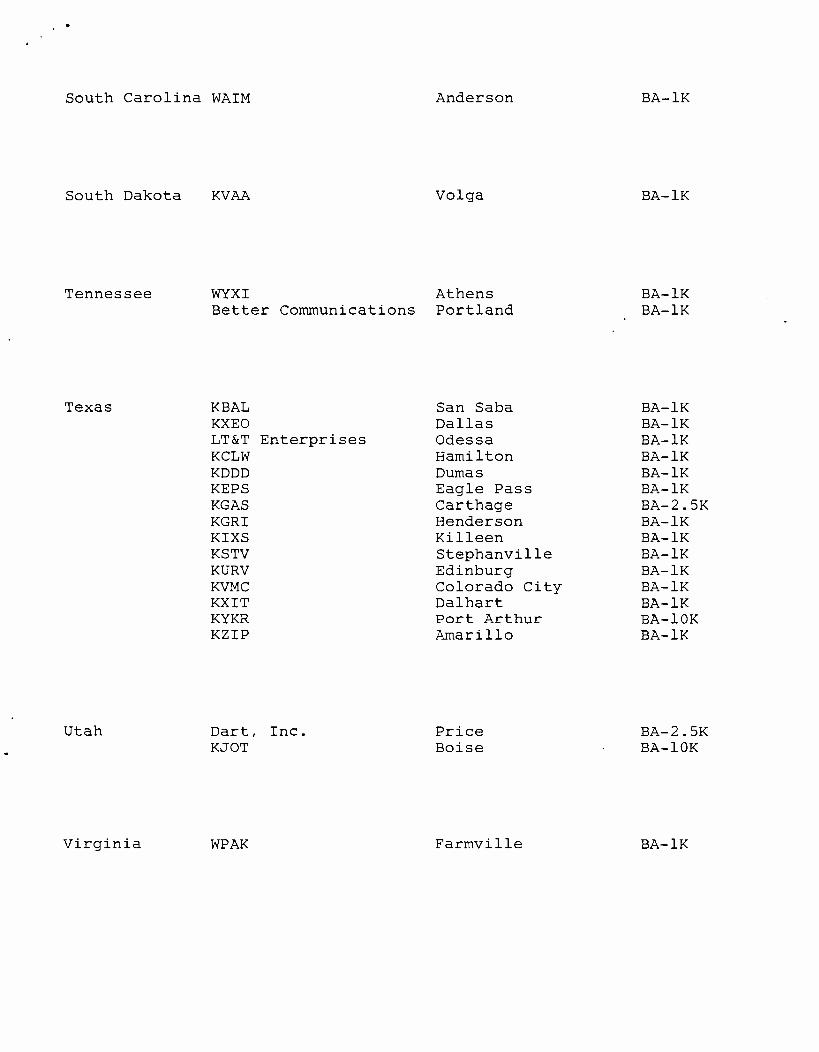
South Carolina WAIM Anderson BA -1K
South Dakota KVAA Volga BA -1K
Tennessee WYXI Athens BA -1K Better Communications Portland BA -1K
Texas KBAL San Saba BA -1K KXEO Dallas BA -1K LT &T Enterprises Odessa BA -1K KCLW Hamilton BA -1K KDDD Dumas BA -1K KEPS Eagle Pass BA -1K KGAS Carthage BA -2.5K KGRI Henderson BA -1K KIXS Killeen BA -1K KSTV Stephanville BA -1K KURV Edinburg BA -1K KVMC Colorado City BA -1K KXIT Dalhart BA -1K KYKR Port Arthur BA -10K KZIP Amarillo BA -1K
Utah Dart, Inc. Price BA -2.5K KJOT Boise BA -10K
Virginia WPAK Farmvilie BA -1K
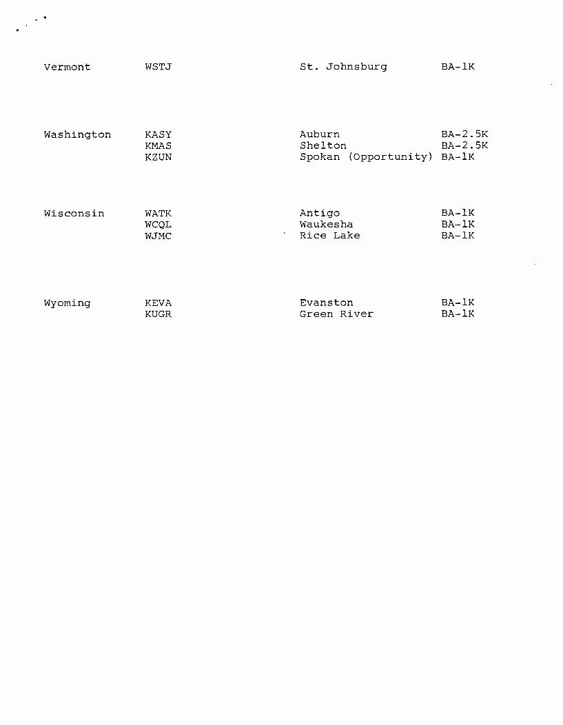
Vermont WSTJ St. Johnsburg BA -1K
Washington KASY Auburn BA -2.5K KMAS Shelton BA -2.5K KZUN Spokan (Opportunity) BA -1K
Wisconsin
Wyoming
WATK Antigo BA -1K WCQL Waukesha BA -1K WJMC Rice Lake BA -1K
KEVA KUGR
Evanston Green River
BA-1K BA-1K
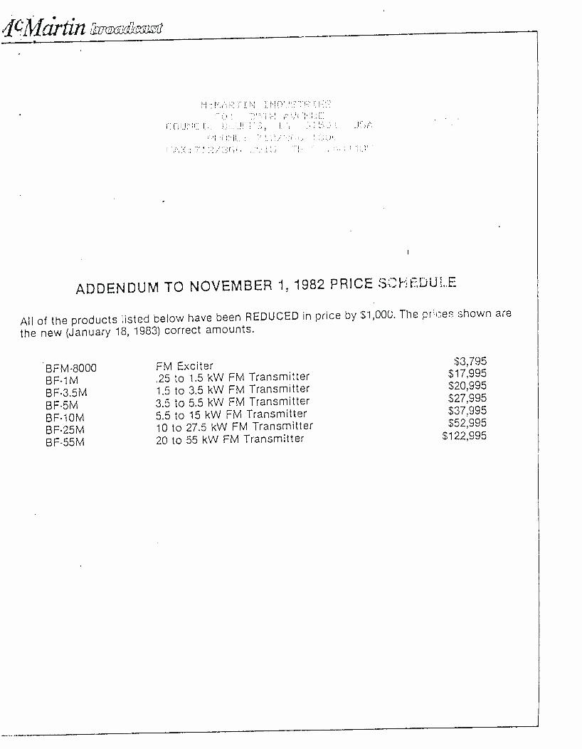
.
tin Inlzi7cnoi
ADDENDUM TO NOVEMBER 1, 1982 PRICE S t- t:;ú LE
All of the products listed below have been REDUCED in price by $1,000. The pr'ces shown are
the new (January 18, 1983) correct amounts.
BFM -8000 FM Exciter $3,795
BF-1M .25 to 1.5 kW FM Transmitter $17,995
BF -3.5M 1.5 to 3.5 kW FM Transmitter $20,995
BF-5M 3.5 to 5.5 kW FM Transmitter $27,995
BF -10M 5.5 to 15 kW FM Transmitter $37,995
BF-25M 10 to 27.5 kW FM Transmitter $52,995
BF -55M 20 to 55 kW FM Transmitter $122,995
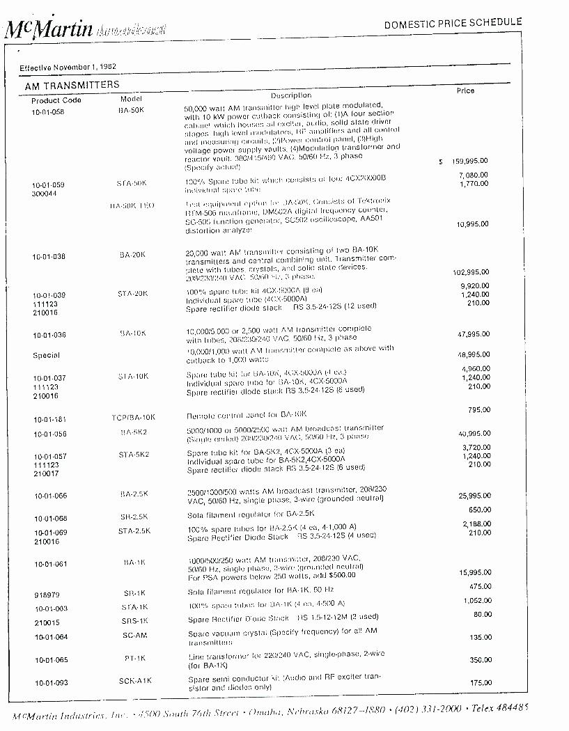
McMartin DOMESTIC PRICE SCHEDULE
Effective November 1, 1982
AM TRANSMITTERS
Product Codo
10- (1.058
10.01.059 300044
10.01.038
10- 01.039 111123 210016
10.01.036
Special
10.01.037 111123 210016
10.01.181
10.01.056
10.01.057 111123 210017
10.01.066
10.01.068
10. 01.069 210016
10-01-061
918979
10 -01 -063
210015
10. 01.064
10-01-065
10- 01.093
Modol
BA-50K
STA -50K
11A -50K TB)
BA -20K
STA-20K
Description
50,000 watt AM transmitter high level plate modulated,
with 10 kW power cutback consisting of: (1)A four section
cabinet which houses all exciter, audio, solid stale driver
stage:;, high level modulator:;, I1F amplifiers and all control
and measuring circuit;, (2)Power control panel, (3)High
voltage power supply vaults, (4)Modulation transformer and
reactor vault. 380/415/460 VAC, 50/60 Hz, 3 phase
(Specify actual)
100% Spare tube kit which consists of lour 4CX200006
individual :;pare Iuhe
1 st equipment option toi LtA -50K. Consists of Tektronix
RTM -50G mainframe, DM502A digital frequency counter,
SG -505 function generator, SC502 oscilloscope, AA501
distortion analyzer
20,000 watt AM transmitter consisting of two BA -10K
transmitters and central combining unit. Transmitter com-
plete with tubes, crystals, and solid state devices.
208/230/240 VAC, 50/00 1-L-, 3 phase.
100% %% spare tube kit 4CX -5000A (8 ea)
Individual spare tube (4CX- 5000A)
Spare rectifier diode stack RS 3.5.24.12S (12 used)
BA -10K 10,000/5,000 or 2,500 watt AM transmitter complete with tubes, 208/230 /240 VAC, 50/60 Hz, 3 phase
10,000 /1,000 watt AM transmitter complete as above with
cutback to 1,000 walls
STA -10K Spare tube kit for BA-10K, 4CX -5000A (4 ea.)
Individual spare tube for BA -10K, 4CX -5000A
Spare rectifier diode stack RS 3.5-24-12S (6 used)
TCP /BA -10K
BA-5K2
STA -5K2
RA -2.5K
SR -2.5K
STA -2.5K
11A -1K
SR-1K
STA-1K
SRS-1K
SC -AM
PT-1K
SC K-Al K
Remote control panel for BP, -10K
5000 /1000 or 5000 /2500 watt AM broadcast transmitter (Single meted) 2011/230/24() VAC, 50H00 Hz, 3 phase
Spare tube kit for BA -5K2, 4CX -5000A (3 ea)
Individual spare tube for BA- 5K2,4CX -5000A
Spare rectifier diode stack RS 3.5.24.12S (6 used)
2500/1000/500 watts AM broadcast transmitter, 208/230
VAC, 50/60 Hz, single phase, 3 -wire (grounded neutral)
Sofa fitarnent regulator for BA -2.5K
100% spare tubes for BA -2.5K (4 ea, 4.1,000 A)
Spare Rectifier Diode Stack RS 3.5-24-12S (4 used)
1000/500/250 watt AM transmitter, 208/230 VAC,
50/60 I-Iz, single phase, 3 -wire (grounded neutral)
For PSA powers below 250 watts, add $500.00
Sole filament regulator for BA -1K, 60 Hz
100 " /o span; tubes for ItA -1 K (4 ea, 4-500 A)
Spare Rectifier Diode Stack RS 1.5-12-12M (2 used)
Spare vacuum crystal (Specify frequency) for all AM
transmitters
Line transformer for 220/240 VAC, single- phase, 2 -wire
(for BA -1.K)
Spare serai conductor kit (Audio and RF exciter tran-
sistor and diodes only)
Price
$ 159,995.00
7, 080.00 1,770.00
10,995.00
102,995.00
9,920.00 1,240.00
210.00
47,995.00
48,995.00
4,960.00 1,240.00
210.00
795.00
40,995.00
3,720.00 1,240.00
210.00
25,995.00
650.00
2,188.00 210.00
15,995.00
475.00
1,052.00
80.00
135.00
350.00
175.00
Afr'Mnrtirr Inrhu.striu.s, Inc . 1S(X) South 76th Street Ozrrnhrr, ?Vein-risk(' 68127---1880 (402) 331-20(X) Telex 484485

FM TRANSMITTERS
Product Codo Model
10-01 -078 BF -55h1
10-01-046 BF25M
10-01047 STF25K
210016
210017
920039 511-25M
10-01-045 BF-10M
10-01-048 STF-10K
210015
210016
10-01-040 13F-5M
10-01-027 STF51'.
210018
10-01-026 BF-3.5M
10-01-027 STF-3.5K 210018
10-01-090 BF-1M
10-01-094 STF-1K 210015
ACCESSORIES
10-01-074 APC
10-01-079 ARSt
10-01-075 ARS-3
10-01-076 TOP-1
2
Description
20 55 kw FM broadcast transmitter, complete with one
exciter (combined output of two BF -25M transmitters), 208/230/240 VAC, 50/60 I i; 3 phase
10 - 27.5 kw FM broadcast transmitter, complete with
excitor and tubes, 208/230 /240 VAC, 50 /60 Hz,
3-phase
Spare tube kit for BF -25M (i- 4CX250BC, 1.3CX3000A7,
1.3CX20(X)0A7) Spare Rectifier Diode Slack, Low Voltage IiS 1.5.12.125 (4 used) Spare Rectifier Diode Stack, High Voltage
RS 3.5-24.15S (6 used)
:->ola filament regulator Inr. BF-251v1 transmitter
5.5 - 15 kw FM broadcast transmitter, complete with
exciter and tubes, 208/230/240 VAC, 50 /GO Hz,
3 -phase
Spare tube kit for BF -10M (i- 4CX250BC, 1.3CX1500A7,
i- 3CX100Q0A7) Spare Rectifier Diode Stack, Low Voltage RS 1.5-12-12M (2 used) Spare Rectifier Diode Stack, High Voltage RS 3.5-24-12S (6 used)
3.5 5.5 kw PM broartcrc,t transmitter, complete with
exciter and tube:;, 2(w/230/240 VA(.:, 50/60 f-L, 3-phase
standard, single phase (optional at $1,500.00 additional cota)
Spare tube kit for BF -5M (2- 4CX2508C, 1- 3CX3000A7)
Spare Rectifier Diode Stack RS 3.5-24-12S (4 used)
1.5 3.5 kw FM transmitter, complete with exciter and
tubes, 208/2:30/240 VAC, 50/60 Hz, single phase
standard, 3 phase (optional al :I:1,5(X).00 additional coot)
Spare tube kit for 13F -3.5M (2- 4CX250BC, 1.3CX3000A7)
Spare Rectifier Diode Slack RS 3.5-24-12S (4 used)
.25 - 1.5KW FM broadcast transmitter, complete with
exciter and tubes, 208/230/240 VAC, 50/60 Hz, single
phase, 3 -wire (grounded neutral)
Spare tube kit for BF -1M (i- 3CX1500A7/8877) Spare Rectifier Diode Stack RS 1.5-12-12M (2 used)
Auto.rnatic power control for FM transmitter
Single phase AC detector with auto restad
thrue phase AC detector with :Hato restart
Transmitter control panel for remote control for AM or FM
transmitter (Specify model numbers when ordering)
Price
S 123,995.00
53,995.00
2,891.00
210.00
210.00
1,050.00
38,995.00
2,330.00
80.00
210.00
28,995.00
870.00 210.00
21,995.00
870.00 210.00
18,995.0)
574.0) 50.07
530.00
375.00
485.00
795.00
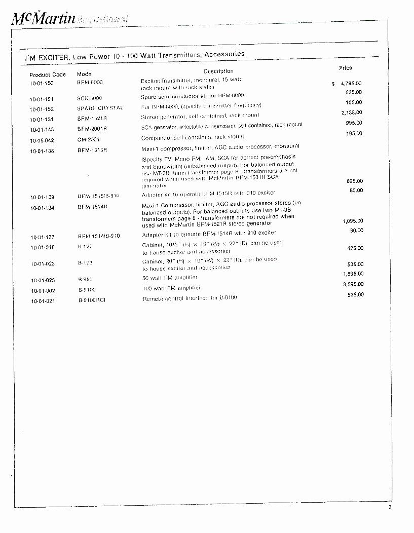
MC-1'dfartiil
FM EXCITER, Low Powor 10 - 100 Watt Transmitters, Accessories
Product Codo Model
10-01.150 BF 8000
10. 01.151
10. 01.152
10- 01.131
10. 01.143
10-05 -042
10. 01.138
10.01.139
10- 01.134
10. 01.137
10.01 -01G
10.01.023
10.01.025
10-01-002
10-01-021
SCK14000
SPARE CIiYSTAI.
BFM-1521R
BFM-2001R
CM-2001
BFM1515R
BFMI01SIB9IO
BFM-1514R
BFM151418910
Description
Exciterfrransmitter, monaural, 15 watt
rack mount with rack slides
Spare semi -conductor kit for BFM -8000
For BFM 0000, (specify transmitter frequency)
Stereo generator, sell contained, rack mount
SCA generator, selectable compression, sell contained, rack mount
Compandor,self contained, rack mount
Maxi -1 compressor, limiter, AGC audio processor, monaural
(Specify TV, Mono FM, AM, SCA for correct pre -emphasis
ancf bandwidth) (unbalanced output). For balanced output
use MT -3B item:; transformer page 8 - transformers are not
required when used with McMartin lIFM -1531R SCA
generator
Adapter kit to operate 13FM15151) with 910 exciter
Maxi -1 Compressor, limiter, AGC audio processor stereo (un
balanced outputs). For balanced outputs use two MT -3B
transformers page 8 - transformers are not required when
used with McMartin BFM-1521R stereo generator
Adaptor kit to operate BFM-1514R with 910 exciter
B -122 Cabinet, 101/2 " (hi) c 19" (W) x 22" (D), can he used
to house exciter and accessories
B -123 Cabinet, 20" (i-I) x 1t)" (VV) >: 22" (D), can be usaci
to house exciter and acces.;or ies
ß -950 50 watt FM amplifier
B -9100 100 watt FM amplifies
B- 9100RCI Remote control interface for .EB -9100
Price
3 4,795.00
535.00
105.00
2,135.00
995.00
195.00
695.00
00.00
1,095.00
80.00
425.00
535.00
1,895.00
3,595.00
535.00
3
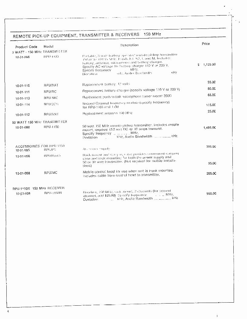
REMOTE PICKUP EQUIPMENT, TRANSMITTER & RECEIVERS 150 MHz
Product Code Model Description Price
3 WATT 150 MHz TRANSMIT TER
1001.086 I11'11t ttl3 l'uwcl>b-, :t will battery ,clec;ctucl remote pickup transmitter I5(1;l, Ici t1(1.1!i 101 1/. It;incl': RI, K2, I. mid M. Includes battery, antenna, nticiol>Incne ,uul battery ch;uger. Specify AC voltage lei lucllery charger 110 Vor 220 V. 5 1,125.00
Specify tremtencv MHz. Deviation Id1., Audio il;,nclwidtll kHz
10- 01.115 RPUIHAT Replacement hattely, 12 volts 55.00
10.01.111 RPUIHC Replacement battery charger (specify voltage 110 V or 220 V) 80.00
1001.113 RPUMIC Replecnu.nt push -to -talk microphone turner model 350D 65.00
10-01-114 RPU;.ICI l Second Channel Irequency module (specify frequency) 115.00
(or RPU -1 103 and 1150
10. 01.112 RPUTANT Replacement antenna 150 MHz 25.00
50 WAl I- 150 MHz TRANSMITTER
10.01.088 RPU1150 50 watt 150 MI(z remote pickup transmitter. Includes mobile
mount, requires 13.5 volt DC <rì' 10 amps transmit. Specify frequency ....___ ... _ _ MHz,
Deviation kHz, Audio Bandwidth _.__...___._. kHz
1,495.00
ACCESSORIES EOR FtI'11I IS0 395.00 10.01.095 111'11/PS Ai. I,,,,v,-i supply
10. 01-096 Ill1t /tt c(,c: Iitu.k ncuunl and c,uryirnl c,c,c: imo.,idc::, c:unvunu:nl ca>ryuul
case and rack mounting for both the power supply and
50 or 3(1 wall transmitter. (Not required for mobile installa-
10.01.098 RPUIMC Mobile control head for use when unit is trunk mounted. 265.00
Includes cable from control head to transmitter.
RP11.1150R 150 MHz RECEIVER
10.03.038 RPM 115011
1
Ilc'ccivrr, PA) tvll I:, rar,1, nlc)unl, 7 channels (1or second
ch;uuu:l, add 525.00) :il,ecify 0cquenr,y . ..... MHz,
Duvialion 1<i-1z, Audio Bandwidth ---.---.___--- kHz 950.00
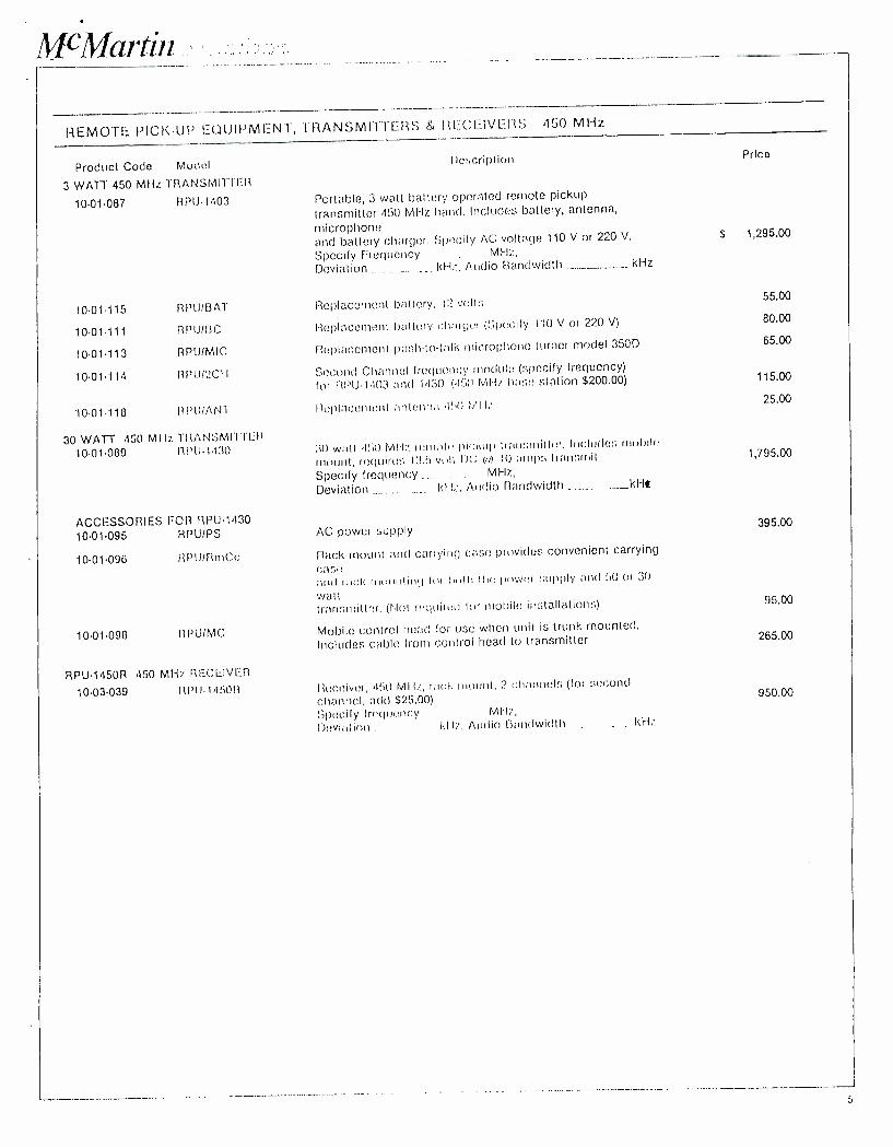
McMartin tint
REMOTE PICK-UP EQUIPMENT, TRANSMITTERS 84 RECEIVERS 450 MHz
Product Codo Model Description Prlco
3 WATT 450 MHz TRANSMITTER
10.01.087 RPU1403 Portable, 3 watt battery operated remote pickup
transmitter 450 MHz band. Includes battery, antenna,
microphone and battery charger. Specify AC voltage 110 V or 220 V. $ 1,295.00
Specify Frequency ..._ MI -tz,
Deviation kHz, Audio Bandwidth .._... kHz
10-01-115 RPUIBAT Replacement battery, 12 volts 55.00
10.01111 RP1J113C Replacement battery charger (Specify 110 V or 220 V) 80.00
10.01.113 RPU/MIC Replacement pushto talk microphone turner model 350D 65.00
10.01.114 RPI)12CI1 Second Channel frequency 'nodule (specify frequency)
for I1131J-1.103 and 1430 (4511 MIli hase station $200.00) 115.00
10.01.118 RI'II /ANT Replacement antenna 41,0 MI l; 25.00
30 WATT 450 MI Iz TRANSMIII t_R
10.01.089 RI'IJ1130 ;tO wall .1111 MHz. rune le pickup Irnnsnrillnr. Includes mobile
mount, lo quires 13.5 voll 1)c; e,) IU amps transmit
Specify frequency . .... MHz,
Deviation .._.... Id Iz, Audio Bandwidth
1,795.00
ACCESSORIES FOR RPU1430 395.00 10.01.095 RPU/PS AC power supply
10.01.096 RPU /RmCc flack mount and carrying curse provides convenient carrying
case and rack in, iJI IiniI lot I4,01 the fu,wcr supply and 50 or 30
wall 95.W transmitter. (Not rcquirr:d or mobile installations)
10.01.098 I1PUIMC Mobile control head for use when unit is trunk mounted. 265.00
Includes cable from control head to transmitter
RPU1450R 450 MHz RECEIVER
10.03.039 II P I.l l 4 50 ß Ilecciver, 450 Ml lz, racl. mount, 2 channels (for second
channel, add $25.00) Specify frequency MIT, Deviation kliz, Audio Bandwidth kHz
950.00
J
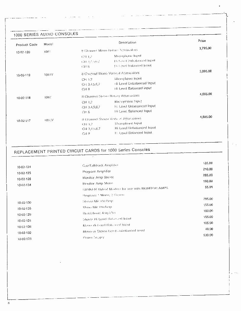
1000 SERIES AUDIO CONSOLES
Product Codo Model
10.0:120 10141 N Channel Mona Ilulnr: Atlenu;tlnr,; 3,795.00
Description Price
(.11
(.II (:1111
Micac,I,Itr,nc Input
I li I v I 1lnl,;il,tnr.cd Input
Hi l evel 11,.11nrlced Input
10. 02.119 1081V 8 Channel Mono Vertical Attenualors
CH 1,2
CH 3,4,5,6,7
CI-1 8
Microphone Input
Hi Level Unbalanced Input
Hi Level Balanced Input
3,895.00
1002118 1082 ii Gh,utnul ;Iteren Rotary Altcnunlor:; 4,695.00
1002.117 I(lti2.V
CH 1,2
C1.1 3.4,5,6,7
CH 8
Microphone Input
I- Ii Level Unbalanced Input
I-1i Level Balanced Input
ti Channel Sturen Viali . tl Ai.lcnuataa,
(,I 11,2 Microphone Input
CII 3,4,1,6,7 I-li Level Unbalanced Input
CH fl Hi Level Balanced Input
4,895.00
REPLACEMENT PRINTED CIRCUIT CARDS for 1000 Series Consoles
10.02.124
10-02-125
10. 02.126
10-02-134
10.02.130
10.02.135
10.02.129
10.02131
10.02.136
10.02.132
I0.02.133
CuClT;tlkh,tcl: nnrpllli,',
Program Amplifier
Mcnlilur Amp Stereo
Monitor Amp Mann
;ANIt.N Ilyhricl Mndul loi twit) Willi M(:)IJIIOIt AN11'1
Ilc(luiril:; 1 N1rntt,,
luruu N1ic 1'ICA11;I)
N1(,nu N4ic l'r(,Ainlr
I lundlthunc Anrl,lilici
l!() I li I_evcl B;,1;111 I'd Inpul
M(,nn Ili I.c:vc.l Il;tlanr1.il Inlrul
Mc,n(, UI `_;Iercn Lcvul lni)l;utce.d Inlnrl
l'owni lrtrl,ltly
185.00
210.00
265.00
160.00
55.00
295.00
155.00
160.00
155.00
105.00
40.00
530.00
(i
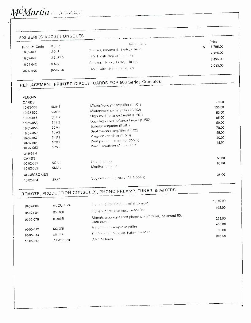
1Vx1Vlatrn l ; ,,
500 SERIES AUDIO CONSOLES
Product Codo
10. 02.041
10- 02.044
10.02.042
10. 02.045
Model
B -501
1350I SA
B.Ci02
B`.i0'2SA
Description
5 mixer, )ixer, monaural, 1 r nic, 4 Iii -bal
13.50I will stet) nitenuaturs
5 mixer, :sera', I Inic, ,I 11' 1'1;11
13 -1)02 with step allent olors
Price
$ 1,795.00
2,125.00
2,495.00
3,025.00
REPLACEMENT PRINTED CIRCUIT CARDS FOR 500 Series Consoles
PLUG-IN
CARDS
10. 02.056
10.02.060
10.02.054
10. 02.058
10.02.055
10-02-059
10.02.057
10.02.061
10.02. -053
WIRE -IN
CARDS
10.02.051 50A1
10-02-052 5MA1
ACCESSORI ES
10.02.064 5RY1
5MP1 Microphone preamplifier (13501)
5MP2 Microphone pleamplilier ([3-502)
513I -11 High level balanced input (13.501)
513112 Dual high level balancer) input (B-502)
5BA1 Booster amplifier (13.501)
SBA2 Dual 1)oosler amplifier (11.502)
5P01 Program amplifier (II -501)
5PG2 Dual mown) amplilici (11-502)
51,ß,1 Iii ir(lul;ilui (All mdel -.:)
Cue allIplifier
Monitor amplifier
Speaker muting relay (All Models)
70.00
135.00
55.00
85.00
50.00
70.00
55.00
80.00
45.00
60.00
80.00
35.00
REMOTE, PRODUCTION CONSOLES, PHONO PREAMP, TUNER, & MIXERS
10. 02.080 ACCU -FIVE
10. 02.081 BR -400
10. 02.076 B20013
10-05-012 MX-5113
10-05-044 MRP7111
10-05018 Al -20011111
5 channel rack mount mini console
4 channel remote mixer amplifier
Mono /stereo equalized phono preamplifier, balanced 600
ohm output
5.(:h:(nncl n)ixc'Ipn)an'plilicr
l'acte, lu' MX .5
AM /1 M tune'
1,375.00
695.00
295.00
450.00
35.00
395.00
7
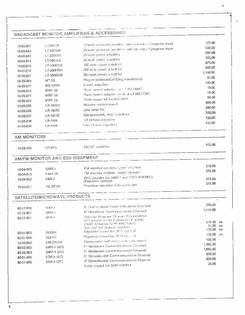
BROADCAST MONITOR AMPLIFIERS & ACCESSORIES
10.05.001 Lf80C/11
1005-043 LT-2521318
10-05-041 LT250[)113
10-05-014 LT5000113
10-05.015 LT1000DIB
10-05-016 LT2000D1E3
10-05-021 LT3500D1B
1005-009 MT-3B
10-05-017 MS1051B
10.05.010 MRP 311
10-05-011 M R P .113
1005-022 M R P 1113
10-05-035 1.13.10001)
10-05-036 LR-1003C
10-05-037 LR1004C
10-05-038 LR-1000
1005-039 1.11- 10011
I2 -watt universal ;unpliher with one ink:, I program input
25 -watt universal amplifier :vith two rnic, 2 program input
25 watt power amplifier
50 -watt power amplifier
100 -watt power amplifier
200 -watt power amplifier
350 -wall power amplifier
Plug -in balanced/bridging transforn-rer
5 -watt amplifier (tack nuumt nctaptor liri 1 1;10(;/1013(
Rack mount adaplor for deuil LL SOC /1USC
Rack mount kit for MS- 10513
Munilor control panel
Line amplifier
Compressor /Limiter amplifier
1/3 Octave eguail/or
one I)el;ivr cvlu:ili:r i
AM MONITORS
170.00
520.00
290.00
355.00
475.00
845.00
1,140.00
31.0E
120.00
19.00
15.00
39.00
500.00
290.00
345.00
720.00
415.00
10. 03.104 RF-0513 AM RE amplifier 975.00
AM /FM MONITOR AND EBS EQUIPMENT
10.04.003
10.04.013
10.04.002
AMR -1
PMR -1D
EBS -2
10-04-011 TG-'IJEBS
AM monitor receiver, ,indic channel
FM monitor receiver, single channel
ERS decoder for AMR -1 and 17M11- 10IFM11.5 (Two -lone system) Precision two -lone 1=135; generator
210.00
275.00
275.00
375.00
SATELLLTE/MICROWAVE PRODUCTS
60.01.002 SD11.1 IF Oernnc(ulalor Communications Channel
60- 02.001 SM11 -1 IF [Modulator Communications Channel
60. 01.001 SPtt :3 :Satellite Program Channel Demodulator ('_,ill rcc:uive ulr to :3 Channel:: il within ;' rr:ll.. between 5:' -13;3 Iv111.- hand) :! rl nut :11cl channel c ;ry:rtals
60. 01.003 550306 Expander hoard for SI'I1 -:t I :t >: I)
60-01-004 550317 Expander hoard foi til'II-3 (2x 1)
10. 05.042 CM- 2001113 Compandor, sell contained, rack nwunl
60-02-002 SMI3.4 (AC) IF Modulates Communications Channel
60. 02.003 SMR -4 (DC) IF Modulator Communications Channel
60.01.005 SDR -4 (AC) IF Demodulator Communications Channel
60.01.006 SDR -4 (DC) IF Demodulator Communications Channel
Extra crystal Ior SMR- 4 /SDR-4
6
550.00
1,115,00
615.00 ea. 17.00 ea.
115.00 ea.
115.00 ca.
195.00
1,495.00
1,695.00
850.00
850.00
25.00
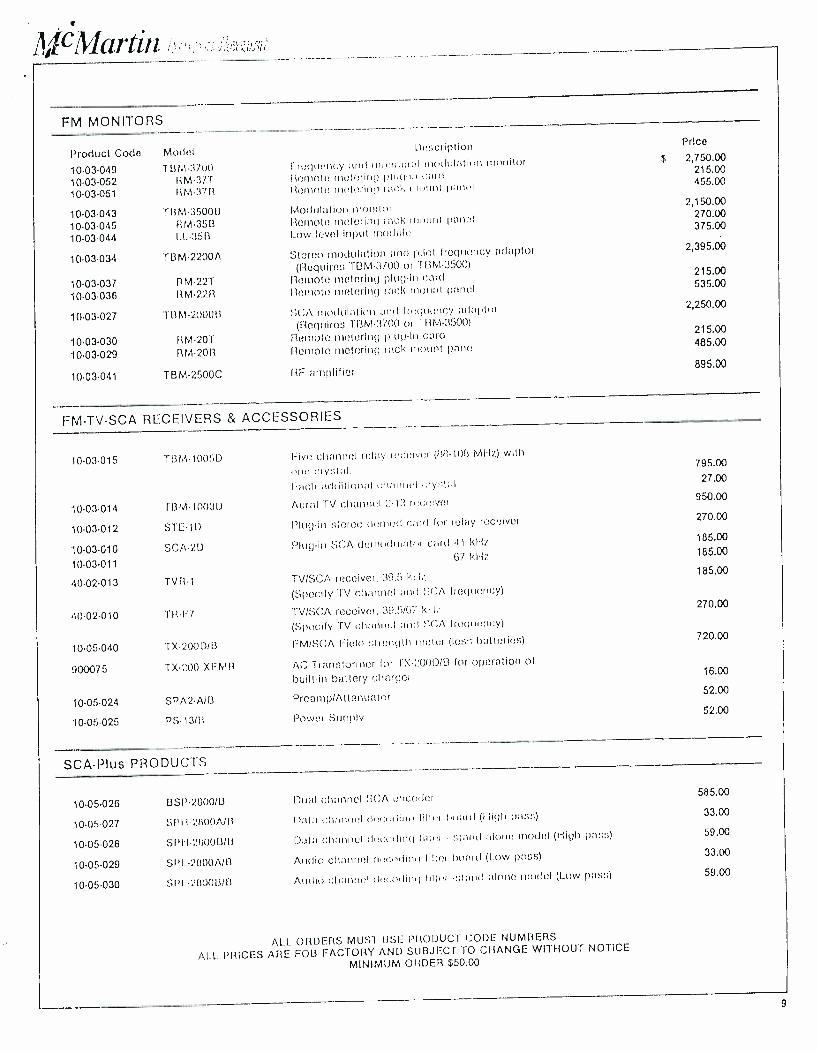
/ lt¡.f 1'ilrtln
FM MONITORS
Product Codo Model !inscription
10. 03.049 TDM-3-70() l requency and monaural modulation monitor
10 -03 -052 RM-37T Remote metering plut! -in cart!
10.03.051 RM37R Ilemote metering racle mount panel
10- 03.043 TBM3500B Modulation monitor
10. 03.045 RM-35B Remote metering rack tumult panel
10. 03.044 l.l.35B Low level input module
10. 03.034 TBM2200A Stereo modulation and pilot frequency adaptor
(Requires T0M -3700 or 'FUM -3500)
10. 03.037 RM-22T nomote metering plug-in card
10. 03.036 11M-22R Remote metering rack mount pend
10.03.027 1- B M 2000 8 5CA modulation ;11ík1 frequency adaptor (Requires TBM3700 or TIIM3500)
10.03.030 RM-20T Rernote metering plug -In card
10-03-029 RM20R Remote metering rack mount panel
10.03.041 TBM-2500C RF amplifier
Price
$ 2,750.00 215.00 455.00
2,150.00 270.00 375.00
2,395.00
215.00 535.00
2,250.00
215.00 485.00
895.00
FMTVSCA RECEIVERS & ACCESSORIES
10-03-015 TDM-1005D Five channel relay receiver (148- 108 Mt-Iz) with
one. eiy:,lal. Pitch additional channul cryr ;lal
10-03-014 TBM1003D Aural TV channel 2.13 receiver
1003012 STEW Plug -in stereo deno(I card for relay receiver
10-03-010 SCA2D Plug -in SCA dcmndulalor cart! 41
67 kHz 10-03-011
40.02013 TVR1 TV/SCA receiver, 39.5 RI Iz.
(Specify TV channel and S(;A frequency)
40-02-010 -I F1-í-7 TV/SCA receiver, 39.507 RR'.
(Specify Tv channel and SCA frequency)
10-05-040 TX-200D/8 FM /SCA Field strength motor (less; batteries)
900075 TX-200 XFMR AC Transformer for l X- Z00DIB for operation of
built -in battery charger
10-05-024 SPA2A/B Preamp /Attenuator
10-05-025 PS-13113 Power Supply
795.00
27.00
950.00
270.00
185.00
185.00
185.00
270.00
720.00
16.00
52.00
52.00
SCA -Plus PRODUCTS
10.05.026 DSP2800fB Dual channel SCA encoder
10.05 -027 SP l I21100A/11 Data channel decoding filler hoard (I ligh pal ;: ;)
10.05.028 SPi-121100WO Data channel dota. ling filter stand alone model (High pass)
10.05.029 SPL2800A/B Audio channel decoding filter board (Low pass)
10.05.030 SPI- -2800 DID Audio channel det.oIlirnl filler -sta ici alone model (I_ow pas:;)
585.00
33.00
59.00
33.00
59.00
ALL ORDERS MUST USE PRODUCT CODE NUMBERS
ALL PRICES ARE FOB FACTORY AND SUBJECT TO CHANGE WITHOUT NOTICE
MINIMUM 011DER $50.00
9
FM so
sys ems
Mc Martin.
McMartin Industries Inc. 4600 South 76th Street Omaha, Nebraska 68127 Phone (402) 331 -2000