Embed Size (px)
Citation preview
Design, Resea rch
Production, Op, ration
Se p te#n4e4, 194x2 N U M 8 E R 4 7 2
35c IN U.S.A.
www.americanradiohistory.com

Not when YOU'RE EQUIPPED TO HANDLE THEM
In addition to the electrical charac- teristics, many customers' application problems are related to the physical appearance and dimensions of their transformer components. Fortunate- ly, the UTC sheet metal division sup- plies practically all the housings, laminations, brackets, and other de- vices which control the mechanical characteristics of UTC units. Instead of restricting designs to specific cases, the sheet metal division can run off a
special case to more closely fit the final transformer dimensions, or to effect the particular mounting provi- sions required by the application.
The sheet metal division has
drawing, forming, and other press facilities to cover the entire gamut of transformer housings from tiny transformer channels, to large oil tanks for broad- cast and industrial service. Since these housings are produced at UTC, fast service can be given.
Illustrated are a few (just a very few) typical cases as supplied for some special applications
IF YOU HAVE A SPECIAL PROBLEM, MAY WE HAVE AN OPPORTUNITY TO COOPERATE?
TREET NEW YORK. N. www.americanradiohistory.com
8aß Iffetc0 a
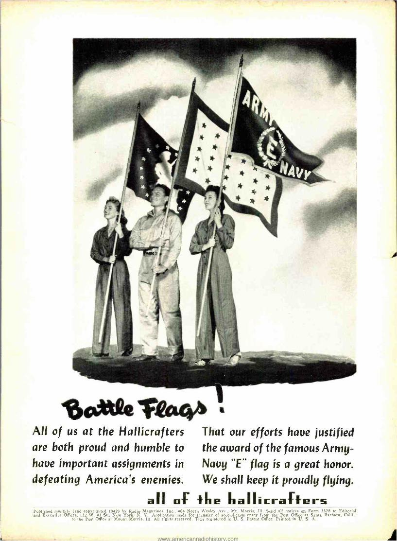
All of us at the Hallícra f ters That our efforts haue justified are both proud and humble to the award of the famous Army - haue important assignments in Nauy LtE" flag is a great honor. defeating America's enemies. We shall keep it proudly flying.
aII of fñe ñallirrafters Published monthly (and copyrighted 1942) by Radio Magazines, Inc., 404 North Wesley Ave., Mt. Morris, Ill. Send all notices on Form 3578 to Editorial and Executive Offices, 132 W. 43 St., New York, N. Y. Application made for transfer of second -class entry from the Post Office at Santa Barbara, Calif.,
t3 the Post Office at Mount Morris, Ill. All rights reserved. Title registered in U. S. Patent Office. Printed in U. S. A.
www.americanradiohistory.com
EDITORIRE
RADIO AND ELECTRONICS
Definitions, like the four freedoms, cannot be estab- lished without effort. Both words and freedoms can be tampered with or loosely applied.
There is now some question as to the proper defini- tions of the words Radio and Electronics ; and differ- ences of opinion as to whether or not they are synony- mous. As obvious as the answer is, it presumably needs clarification in some quarters.
The word Electronics was coined by the McGraw - Hill Publishing Company as the name for a so- called "horizontal" magazine to straddle the whole field built up around the electron tube. By virtue of the ever - increasing number of applications for the electron tube and the undisputed fact that the name is a "nat- ural," Electronics has become a generic term. If it is to he correctly defined, then it covers, among other things, the field of Radio ; hut, by the same token, is not synonymous to it : for Radio is but one bra:ch of the Electronic field.
There is a tendency on the part of many radio pub- lishers to hop aboard the electronics bandwagon, either by instituting new "horizontal" papers in this field, or changing "vertical" papers to cover the broader field. Whether or not there is room for all of them, we do not profess to know. We do know, however, that were all radio magazines to follow suit. the division of attention or scattering of effort would work a hardship on the thousands of engineers, tech- nicians and operators who deal almost exclusively with radio frequencies and seldom if ever deal with any other phase of electronics.
Radio, as a branch of electronics, is a large field in itself, and will be larger still after the war. It is en- titled to a magazine devoted exclusively to its in- terests, now and hereafter. RADIO magazine will stick to those interests through hell and high water.
THE ENGINEER AND PETRILLO
One of the latest of a string of orders issued by James C. Petrillo, president of the American Federa- tion of Musicians, forbids members to take part in the making of one -shot transcriptions for broadcast stations. This edict is a minor annoyance or a major
IRADIO1 * SEPTEMBER, 1942
catastrophe, depending upon which side of the fence one is on ; but, in any event, it poses a nice problem for engineers who contribute in one manner or an- other to technological progress, and feel, along with Mr. Van Dyke, that the engineer should have some voice in sociological matters.
We said, in an editorial in the August issue, that should the engineer make the mistake of thinking that life can be arranged to fit a plan derived from an ideal, then the reality of life as contradistinguished from the reality of pure truth will have escaped him, and the effort to improve society will have been in vain. Mr. Petrillo's ban on electrical transcriptions is a perfect example of the oil- and -water characteristics of idealistic planning and life as she is lived.
It is an interesting commentary on modern life that something the engineer conceived and developed may now not be used by him or for him. It is also sad ; and more than likely a warning of similar con- flicts between technological progress and the profes- sions or crafts such progress appears to endanger. The Petrillos of this world do not react to truths or logic, and more than likely can be "convinced" by nothing less than the counter force of an engineering power group in the form of a guild. As displeasing as such a setup may sound to engineers who never wish to do anything more than mind their own busi- ness, a union of technologists seems to he the only answer.
We do not have to be told that the backlog of war- time inventions will alter the shape of our future society ; nor do we have to have it impressed upon us that progress in all technological fields will tend to snuff out many crafts. Somehow, in some manner, men who have spent their lives in developing pro- ficiency in a given trade will have to be reconditioned and placed elsewhere, and this cannot be done entirely by planning. The engineer will have to make his voice heard and his power felt ; else there will be a peck of trouble, and our technological gains will sour the world.
We hold with Mr. Van Dyke that something should be done. Discussions should take place now, before the wartime backlog of developments is released.
M.L.M.
5
www.americanradiohistory.com
TR.IPLETT INS T RUML1T9
6
`\b
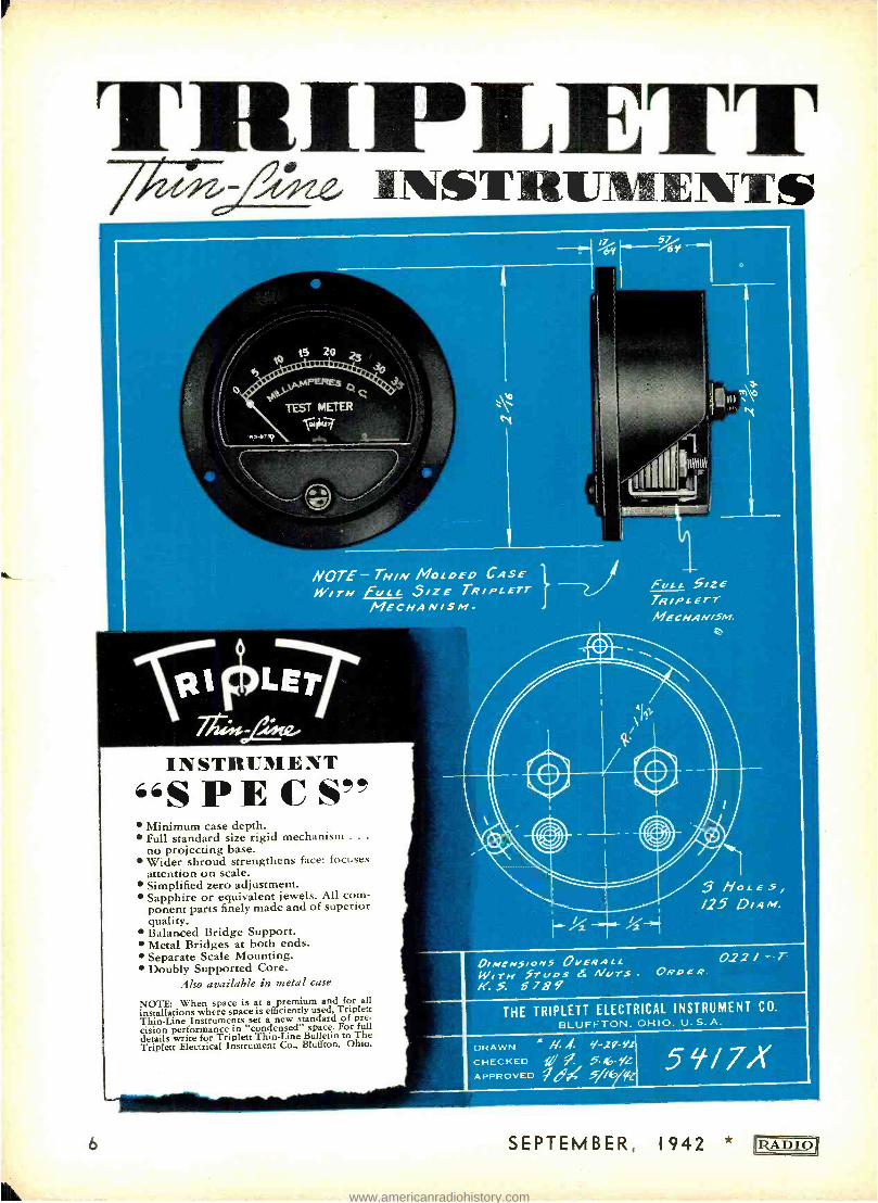
NOTE- TH /N MOLDED CASE W /TH Ft/Lc S /ZE TR /PLETr
MECHAN /SM
INSTRUMENT "S PE C S"
Minimum case depth. Full standard size rigid mechanism . . .
no projecting base. Wider shroud strengthens face: focuses attention on scale. Simplified zero adjustment. Sapphire or equivalent jewels. All com- ponent parts finely made and of superior quality. Balanced Bridge Support. Metal Bridges at both ends. Separate Scale Mounting. Doubly Supported Core.
Also available in metal case
NOTE: When space is at a premium and for all installations where space is efficiently used, Triplett Thin -Line Instruments set a new standard of pre- cision performance in "condensed" space. For full details write for Triplett Thin -Line Bulletin to The Triplett Electrical Instrument Co., Bluffton, Ohio.
57 /at'
FULL SIZE TRIP L Err MECHAN /5M.
0//MCNS/ONS OVERALL 144 T/1 Srl/OS f Afars ago 4"
K. S. 8789 THE TRIPLETT ELECTRICAL INSTRUMENT CO.
BLUFFTON, OHIO. U. S. A.
DRAWN i N q-2-9z CHECKED mi- -Kp -yL APPROVED 7d/ 5//flyfe. 5917X
SEPTEMBER, 1942 )RADIO 1
www.americanradiohistory.com
1ZA D I O Published by
RADIO MAGAZINES. INC.
Publication office: 404 N. Wesley Ave., Mt. Morris, Ill. Executive, editorial, and advertising offices: 132 West 43rd St., New York, N.Y. Telephone : CHickering 4- 3278 -9
Editor
M. L. MUHLEMAN
Business Staff Lee Robinson, Publishe
and President
5. R. Cowan, Business Manager and Treasurer
M. L. Muileman, Vice President
and Editor
A. Alan, Circulation Manager
CORRESPONDENCE and ORDERS should
he sent only to our New York office. MANU- SCRIPTS, if unsolicited and uusable, will not be returned unless accompanied by a
stamped. self-a hlressed envelope.
EXECUTIVE. editorial. and advertising offices of Radio Magazines, Inc., are located at 132 West 43rd Street, New York, N.Y., to which address all correspondence, adver- tising copy and cuts should he directed.
SUBSCRIPTION RATES (in U.S. funds): Two years, $5.00, or $3.00 yearly in U.S.A. To Canada and all foreign countries, $4.00
yearly. Twelve issues yearly: hack issues are not included n subscriptions.
NOTE: Because of wartime censorship re-
strictions, we must reserve the right to with- hold from foreign subscribers any issue the regular domestic edition of which is not ap-
proved by the authorities for export without changes. In such cases subscriptions will be
extended so that each subscriber will even- tually receive the number of issues to which he is entitled.
IF YOU MOVE, notify us in advance; we cannot replace copies sent to your old ad- dress. Notice must be received by the 20th of the month preceding the cover date of first issue to go to the new address.
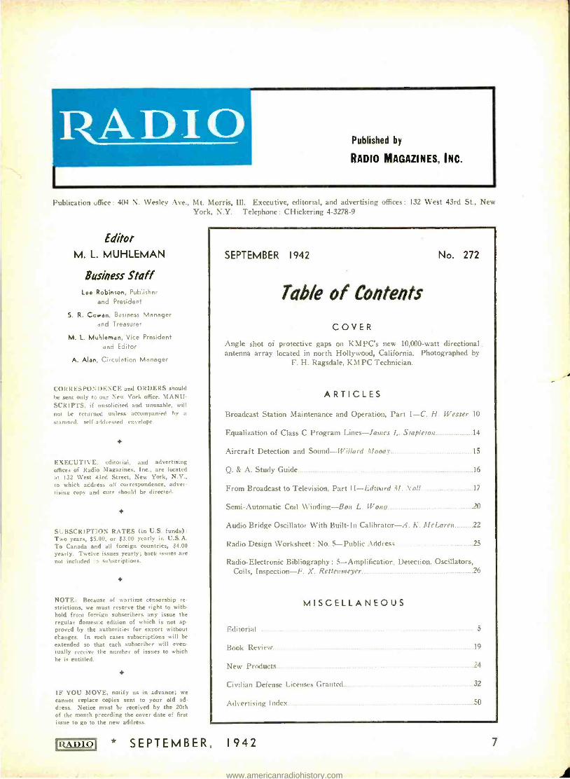
SEPTEMBER 1942 No. 272
Table of Contents
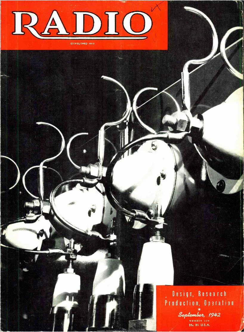
COVER
Angle shot of protective gaps on KMPC's new 10,000 -watt directional. antenna array located in north Hollywood, California. Photographed by
F. H. Ragsdale, KM PC Technician.
ARTICLES
Broadcast Station Maintenance and Operation, Part I -C. H. Wesser 10
Equalization of Class C Program Lines -lames L. Stapleton 14
Aircraft Detection and Sound-Willard Moody 15
Q. & A. Study Guide 1 ,
From Broadcast to Television, Part II-Edward M. Xn // . .. 17
Semi -Automatic Coil Winding -Ron L. Iron!, '0
Audio Bridge Oscillator With Built -In Calibrator -A. K..lIcLaren 22
Radio Design Worksheet : No. 5- Public Address 25
Radio-Electronic Bibliography : 5- Amplificatior. Detection. Oscillators, Coils, Inspection -F. X. Rettennteyer 26
MISCELLANEOUS
Editorial
Book Review - 19
New Products 24
Civilian Defense Licenses Granted 32
Advertising Index. .. 50
* SEPTEMBER, 1942 7
www.americanradiohistory.com
o /11111,11111M11111.11
,
.4.,
14
'
'1VoSis-
11;. 4o7or
C aT1 "
:5511 ; ¡I/ PP'''°°.'''...:
API._ ..,.._oi .. _.,. ...
. ...,,,.. .......;.... -,vir \ rl..., ,.. gttl
,t_:,..., .... __ ,
4
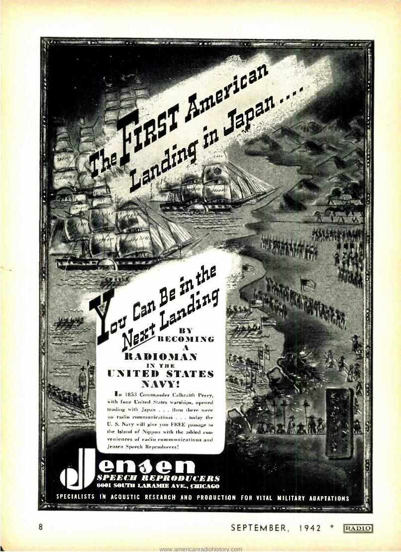
RADIOMAN IN THE
UNITED STATES NAVY!
in 1853 Commander Calbraith Perry, with four United States warships, opened trading with Japan . . . then there were no radio comn at s . . . today the U. S. Navy will give you FREE passage to the Island of Nippon with the added con- veniences of radio communications and Jensen Speech Reproducers!
en4en .
SPEECH REPRODUCER 6601 SOUTH LARAMIE AVE., CHICAGO
S
b SPECIALISTS IN ACO.USTIC RESEARCH AND PRODUCTION FOR VITAL MILITARY ADAPTATIONS %;--- N.0.1/11/040.
8 SEPTEMBER, 1942 IjADIO
www.americanradiohistory.com
IRADIO
1p i
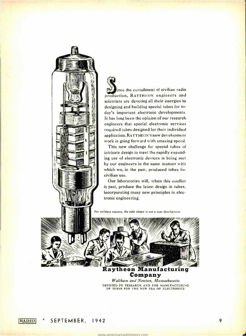
ince the curtailment of civilian radio production, RAYTHEON engineers and scientists are devoting all their energies to designing and building special tubes for to-
day's important electronic developments. It has long been the opinion of our research engineers that special electronic services required tubes designed for their individual application. RAYTHEON'S new development work is going forward with amazing speed.
This new challenge for special tubes of intricate design to meet the rapidly expand- ing use of electronic devices is being met by our engineers in the same manner with which we, in the past, produced tubes for civilian use.
Our laboratories will, when this conflict is past, produce the latest design in tubes, incorporating many new principles in elec- tronic engineering.
For military reasons, the tube shown is not a new development
.. //////,/
! /
oi Raytheon Manufacturing Company
Waltham and Newton, Massachusetts DEVOTED TO RESEARCH AND THE MANUFACTURING
OF TUBES FOR THE NEW ERA OF ELECTRONICS
SEPTEMBER, 1942 9
www.americanradiohistory.com
B4,0acica41 S'aiia#i
MAINTENANCE and OPERATION
PART I
4 Now, more than ever before in the history of broadcasting, it has become imperative that all broadcast station equipment be operated and maintained at peak performance, and at its greatest possible efficiency. The problems in- volved are aggravated in many cases by the fact that some of the older and more experienced engineers have left their berths with broadcast stations, and are now taking part in the war effort in the employ of manufacturing organizations and the armed forces. Added to this is an increasing scarcity of tubes and other necessary replacement parts, with little or no prospect of relief in sight. As a result of these factors and conditions. the average broadcast engineer is more "on his own" now than ever before, and his station's as well as his own survival depend frequently upon his ingenuity and originality in devising ways and means of maintaining his equipment in top -notch condition. yet maintaining the
C. H. WESSER Chief Engineer, W45D
high standards of performance that have made broadcasting one of the nation's most important and necessary public services.
Station Routines
Since only closely- adhered -to routines, and the keeping of accurate records will make for top efficiency, this paper pre- sents ideas and suggestions in the form of a description of such routines. The establishing of, and adhering thereto will materially ease the task of the broadcast engineer in the operation and maintenance of his equipment.
Rather than using a hypothetical case, the operation and maintenance routines of F.M. Station W45D are used as an example, but not necessarily as an abso- lute standard, although they have shown over a period of more than a year that they cover regular operation very thor- oughly, and have provided good guid- ance for all members of the station's Technical Department. They have made possible a good record of performance
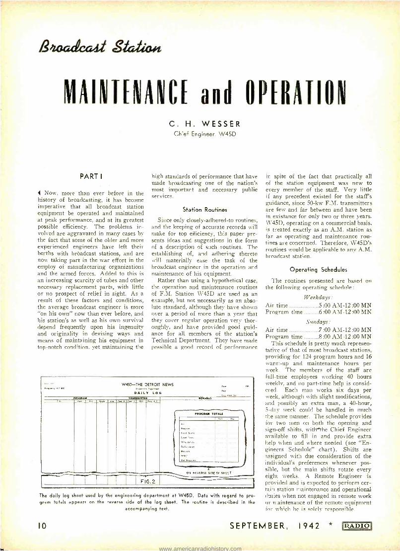
` -- " W45D -THE DETROIT NEWS o,,, Frequency 5 MC F_.ne.. ;. 0.wn..ix
DAILY LOG o" S sheet No.
MOORA M TRAM3MRTO1 *MAR.
PROGRAM TOTALS
Local Stud.
Coal Trail.
Wire
Radio remote
WWI
Fed Programs ' . .... .... .. ..
SIDE
FIG.2
ON REVERSE OF SHEET -- I The daily log sheet used by the engineering department at W45D. Data with regard to pro- gram totals appears on the reverse side of the log sheet. The routine is described in the
accompanying text.
10
in spite of the fact that practically all of the station equipment was new to every member of the staff. Very little if any precedent existed for the staff's guidance, since 50 -kw F.M. transmitters are few and far between and have been in existance for only two or three years. W45D, operating on a commercial basis, is treated exactly as an A.M. station as far as operating and maintenance rou- tines are concerned. Therefore, W45D's routines would be applicable to any A.M. broadcast station.
Operating Schedules
The routines presented are based on the following operating schedule:
Weekdays: Air time 5 :00 AM -12 :00 MN Program time 6:00 AM -12:00 MN
Sundays: Air time 7 :00 AM -12 :00 MN Program time 8 :00 AM -12 :00 MN
This schedule is pretty much represen- tative of that of most broadcast stations, providing for 124 program hours and 16 warm -up and maintenance hours per week. The members of the staff are full -time employees working 40 hours weekly, and no part -time help is consid- ered. Each man works six days per week. although with slight modifications, and possibly an extra man, a 40 -hour, 5 -day week could be handled in much the same manner. The schedule provides for two men on both the opening and sign -off shifts, witlf the Chief Engineer available to fill in and provide extra help when and where needed (see "En- gineers Schedule" chart). Shifts are assigned with due consideration of the individual's preferences whenever pos- sible, but the main shifts rotate every eight weeks. A Remote Engineer is provided and is expected to perform cer- tain station maintenance and operational duties when not engaged in remote work or maintenance of the remote equipment for which he is solely responsible.
SEPTEMBER, 1942 NRADIO
www.americanradiohistory.com
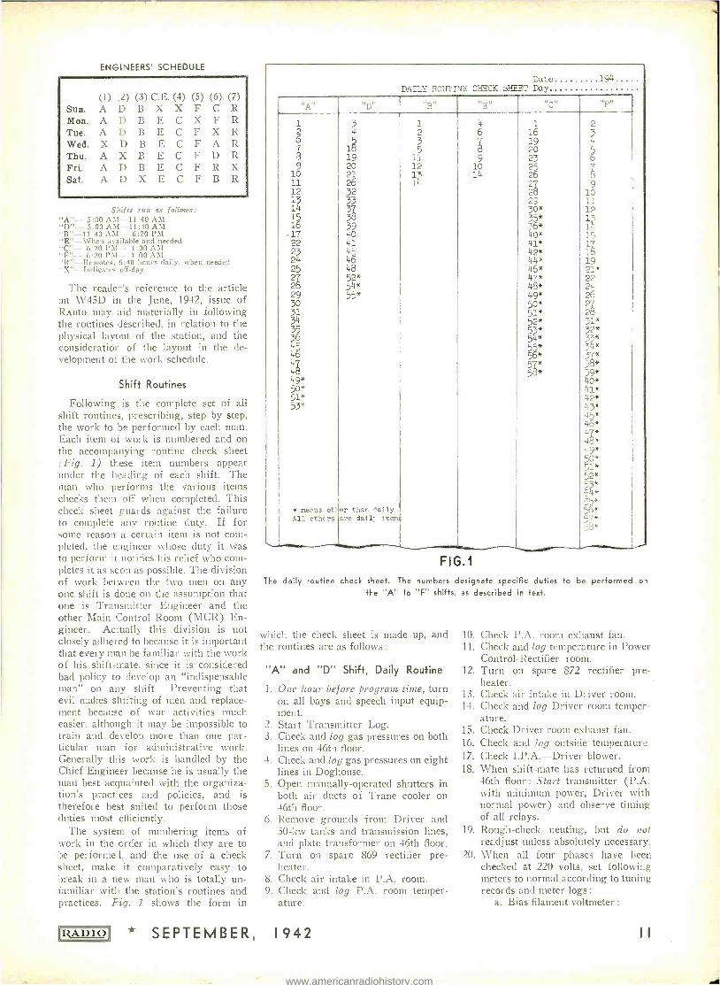
ENGINEERS' SCHEDULE
Sun. Mon. Tue. Wed. Thu. Fri. Sat.
(1) ;2) (3) C.E. (4) (5) (6) (7) A D B X X F C R A D B E C X F R A D B E C F X R X D B E C F A X B E C F D R A D B E C F R X A D X E C F B R
S ;'ifts run as follows: "A "- 5:00 AM -11:40 AM "D "- 5:00 AM -11:40 AM "B"-11-40 AM- 6:20 PM "E" -When available and needed "C "- 6:20 PM- 1:00 AM "F "- 6:20 PM- 1:00 AM "R - Remotes, 6:40 hours daily. when needed "Y "- Indicates off -day
The readers reference to the article on W45D in the June, 1942, issue of RADIO may aid materially in following the routines described, in relation to the physical layout of the station, and the consideration of the layout in the de- velopment of the work schedule.
Shift Routines
Following is the complete set of all shift routines, prescribing, step by step, the work to be performed by each man. Each item of work is numbered and on the accompanying routine check sheet ("Fig. 1) these item numbers appear under the heading of each shift. The man who performs the various items checks them off when completed. This check sheet guards against the failure to complete any routine duty. If for some reason a certain item is not com- pleted, the e_lgineer whose duty it was to perform it notifies his relief who com- pletes it as soon as possible. The division of work between the two men on any one shift is done on the assumption that one is Transmitter Engineer and the other Main Control Room (MCR) En- gineer. Actually this division is not closely adhered to because it is important that every man be familiar with the work of his shift -mate, since it is considered bad policy to develop an "indispensable man" on any shift. Preventing that evil makes shifting of men and replace- ment because of war activities much easier, although it may be impossible to train and develop more than one par- ticular man for administrative work. Generally this work is handled by the Chief Engineer because he is usually the man best acquainted with the organiza- tion's practices and policies, and is therefore best suited to perform those duties most efficiently.
The system of numbering items of work in the order in which they are to be performed, and the use of a check sheet, make it comparatively easy to break in a new man who is totally un- familiar with the station's routines and practices. Fig. 1 shows the form in
RADIO * SEPTEMBER,
Date 194 DAILY ROUTINE CHECK SHEET Day
A "D" "B" "E" "C"
"Fn
2 2 6
.--
9 10 11 12
12 15
17 22 23 2i+
25 2 28 29 30 31
35
36 5
46 48 49* 50* 51* 53*
means ot.ler All others
4
1
20 21 26 32 33
3339
40 41 45 46 48
*
54* 55*
than daily are 3aí1; items
1 2 3 5
11 12 lj 11!
6 7 8
9 10 14
16
19 20 23 25 26 2 28 29*
3365*
40* 41* 42 * 44* 46*
77*
48* 49* 50* 51*
52* *
54* 55* 516*
*
58*
2
6 77
10 11
14 1
5 1
19 21* 22 24 26 2"1
2fß
32* 33* 3 4*
38*
ko* 41* 42* X13* 45* 46* 47* 48* 49* 50* 51* -2*
G3* k
=* 5b* 57* 5*
FIG.1
The daily routine check sheet. The numbers designate specific duties to be performed of the "A" to "F" shifts, as described in text.
which the check sheet is made up, and 10. the routines are as follows : 11.
"A" and "D" Shift, Daily Routine 12.
1. One hour before program time, turn on all bays and speech input equip- ment. Start Transmitter Log.
3. Check and log gas pressures on both lines on 46th floor.
4. Check and log gas pressures on eight lines in Doghouse.
5. Open manually- operated shutters in both air ducts of Trane cooler on 46th floor.
6. Remove grounds from Driver and 50 -kw tanks and transmission lines, and plate transformer on 46th floor.
7. Turn on spare 869 rectifier pre - 20. heater.
8. Check air intake in P.A. room. 9. Check and log P.A. room temper-
ature.
2
13. 14.
15.
16.
17.
18.
19.
1942
Check P.A. room exhaust fall. Check and log temperature in Power Control- Rectifier room. Turn on spare 872 rectifier pre - heater. Check air intake in Driver room. Check and log Driver room temper- ature. Check Driver room exhaust fan. Check and log outside temperature. Check I.P.A. -Driver blower. When shift -mate has returned from 46th floor : Start transmitter (P.A. with minimum power, Driver with normal power) and observe timing of all relays. Rough -check neuting, but do not readjust unless absolutely necessary. When all four phases have been checked at 220 volts, set following meters to normal according to tuning records and meter logs :
a. Bias filament voltmeter
www.americanradiohistory.com
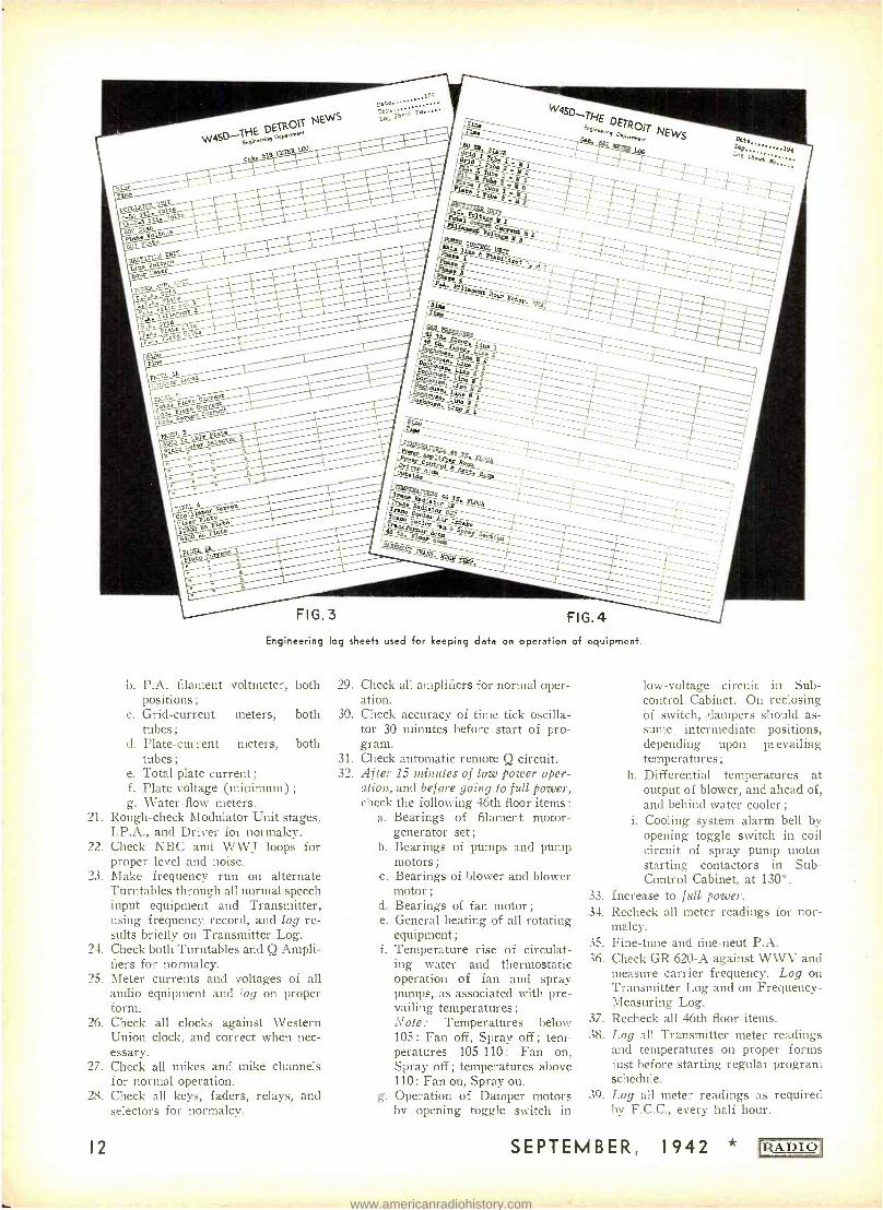
Engineering log sheets used for keeping data on operation of equipment.
b. P.A. filament voltmeter, both 29. positions ;
c. Grid -current meters, both 30. tubes;
d. Plate -current meters, both tubes ; 31.
e. Total plate current ; 32. f. Plate voltage (minimum) ;
g. Water -flow meters. 21. Rough -check Modulator Unit stages,
I.P.A., and Driver for normalcy. 22. Check NBC and WWJ loops for
proper level and noise. 23. Make frequency run on alternate
Turntables through all normal speech input equipment and Transmitter, using frequency record, and log re- sults briefly on Transmitter Log.
24. Check both Turntables and Q Ampli- fiers for normalcy.
25. Meter currents and voltages of all audio equipment and ?og on proper form.
26. Check all clocks against Western Union clock, and correct when nec- essary.
27. Check all mikes and mike channels for normal operation.
28. Check all keys, faders, relays, and selectors for normalcy.
12
Check all amplifiers for normal oper- ation. Check accuracy of time tick oscilla- tor 30 minutes before start of pro- gram. Check automatic remote Q circuit. After 15 minutes of low power oper- ation, and before going to full power, check the following 46th floor items :
a. Bearings of filament motor - generator set;
b. Bearings of pumps and pump motors ;
c. Bearings of blower and blower motor ;
d. Bearings of fan motor ;
e. General heating of all rotating equipment ;
f. Temperature rise of circulat- ing water and thermostatic operation of fan and spray pumps, as associated with pre- vailing temperatures ;
Note: Temperatures below 105 : Fan off, Spray off ; tem- peratures 105-110 : Fan on, Spray off ; temperatures above 110: Fan on, Spray on.
g. Operation of Damper motors by opening toggle switch in
low- voltage circuit in Sub - control Cabinet. On reclosing of switch, dampers should as- sume intermediate positions, depending upon pt evailing temperatures ;
h. Differential temperatures at output of blower, and ahead of, and behind water cooler ;
i. Cooling system alarm bell by opening toggle switch in coil circuit of spray pump motor starting contactors in Sub - Control Cabinet, at 130 °.
33. Increase to full power. 34. Recheck all meter readings for nor-
malcy. 35. Fine -tune and tine -neut P.A. 36. Check GR 620 -A against W W V and
measure carrier frequency. Log on Transmitter Log and on Frequency - Measuring Log.
37. Recheck all 46th floor items. 38. Log all Transmitter meter readings
and temperatures on proper forms just before starting regular program schedule.
39. Log all meter readings as required by F.C.C., every half hour.
SEPTEMBER, 1942 * ¡IjADIO
www.americanradiohistory.com
40. Log all transmitter meter readings on proper forms every two hours.
41. Check all items on 46th floor hourly. 42. At about middle of shift, check all
tuning adiustments. 43. At about middle of shift, visit and
check basement transformer room. 44. At about middle of shift, visit and
check 46th floor transformer room. 45. Enter all discrepancies on Transmit-
ter Log. 46. Enter all n-aintenauce work in Work
Report Book. 47. Before going off duty, total and enter
program time on back of Trans- mitter Log.
48. Acquaint your relief man with any and all unusual items that occurred on your s =lift. Note: On Sunday of every week. in addition So daily routine, do the following:
49. Check water flow interlocks. 50. Check air flow interlocks. 51. Check filament supply filter fuses. 52. Check and clean filters in water sup-
ply. 53. Measure Bias Supply voltage, and
log on Transmitter Log. 54. Check filament m.g. set bearings for
play, commutator for scores, brushes
for wear, tension and seating, and any replacement requirements.
55. Check and service Relay Supply m.g. set in shop.
"B" and "E" Shift, Daily Routine
Start new Transmitter Log. 2. Log Transmitter meter readings
every half hour, as required by F.C.C.
3. Early during this shift, check GR 620 -A against WWV and measr.tre carrier frequency. Log on Trans- mitter Log and on Frequency -Meas- urement Log.
4. Check all items on 46th floor hourly. 5. At about middle of shift, check all
tuning adjustments. 6. At about middle of shift, visit and
check basement transformer room. 7. At about middle of shift, visit and
check 46th floor transformer room. S. Once per shift, check and log gas
pressure on 46th floor. 9. Once per shift, check and log all
temperatures on proper form. 10. Every two hours, log all Trans-
mitter meter readings on proper form. Enter all discrepancies on Trans- mitter Log.
1.
11.
12. Enter all maintenance work in Work Report Book.
13. Before going off duty, total and enter program time on back of Transmit- ter Log.
14. Acquaint your relief man with any and all unusual items that occurred on your shift.
15. Assist C.E. with records and paper work, when needed.
"C" and "F" Shift, Daily Routine
1.
2.
3.
4. 5.
6.
7.
S.
Start new Transmitter Log. Log Transmitter meter readings every half hour, as required by F.C.C. Early during this shift, check GR 620-A against WWV, and measure carrier frequency. Log on Trans- mitter Log and on Frequency -Meas- urement Log. Check all items on 46th floor hourly. At about middle of shift, check all tuning adjustments. At about middle of shift, visit and check basement transformer room. At about middle of shift, visit and check 46th floor transformer room. Once per shift, check and log gas pressure on 46th floor.
[Continued on page 36]
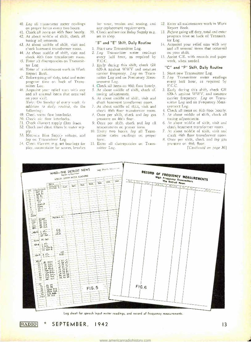
W45D- THE DETROIT NEWS Engineormg D<p.menl
II.NNT LÆTFR N INcs spEEC!<
Log sheet No......
No
_N ÿ_et._.-- 3 62
-36tu46 36 to 48 - 2 1T
Ps.9
D.,.
RECORD
High OF FREQUENCY
MEASUREMENTS Frequency Transmitters The Detroit News
a 1
FIG. 6
D...
'IZADIO]
Log sheet for speech input meter readings, and record of frequency measurements.
* SEPTEMBER, 1942 13
www.americanradiohistory.com
eF4a4atio#t
ClANS C PROGRAM LINES
I Many American broadcast stations use network program lines known as Class "C" lines. These circuits are decidedly inferior in audio quality, but for reasons of economy are used instead of Class "A" lines.
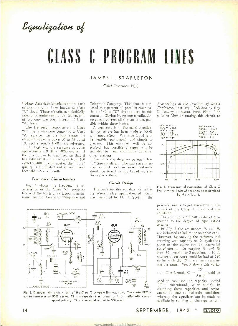
The frequency response on a Class "C" line is very poor compared to Class '`A" service. In the bass range the response curve is down 30 to 35 db at 100 cycles from a 1000 cycle reference. In the high end the response is down approximately 9 db at 4000 cycles. If the circuit can be equalized so that it has substantially flat response from 100 cycles to 4000 cycles most of the "tinny" quality is eliminated and a much more listenable service results.
Frequency Characteristics
Fig. 1 shows the frequency char- acteristics of the Class "C" program line with the limits of variation as main- tained by the American Telephone and
r .04
T1
5000
RFC R3 15M
500 .25 W.
fo JI
JAMES L. STAPLETON Chief Operator, KOB
Telegraph Company. This chart is sup- posed to represent all possible combina- tions of Class "C" circuits used in this country. Obviously, no one equalization curve can correct all the variations pos- sible within these limits.
A departure from the usual equaliza- tion procedure has been made at KOB with good effect. We have found it to be flexible, economical, and simple to operate. This equalizer will be de- scribed, but possible changes will be included to meet conditions found at other stations.
Fig. 2 is the diagram of our Class "C" line equalizer. The parts are in no way critical and in most instances should be found in any broadcast sta- tion's parts stock.
Circuit Design
The basis for this equalizer circuit is the Wien bridge, application of which was described by H. H. Scott in the
1 2.0
5
6J7
250V.
2.0 250 V.
e 2.0 250 V.
1.0 MEG. 3000
5 W. .25W.
V_
ó
.001 MICA
R
MAGNETIC SHIELD
1.0 MEG. .25 W.
R2
2- GANG VARIABLE .00035
J
6L6 3
1.0 250 V.
2 7
Tr 0.0
25V.
T2
á
10 M
20 M 8.0 2 W. Ì 250 V.
500 5 W.
32.0 -I- 350V. O
www.americanradiohistory.com
control. Just before oscillation takes place, a peak as high as 50 db can be had.
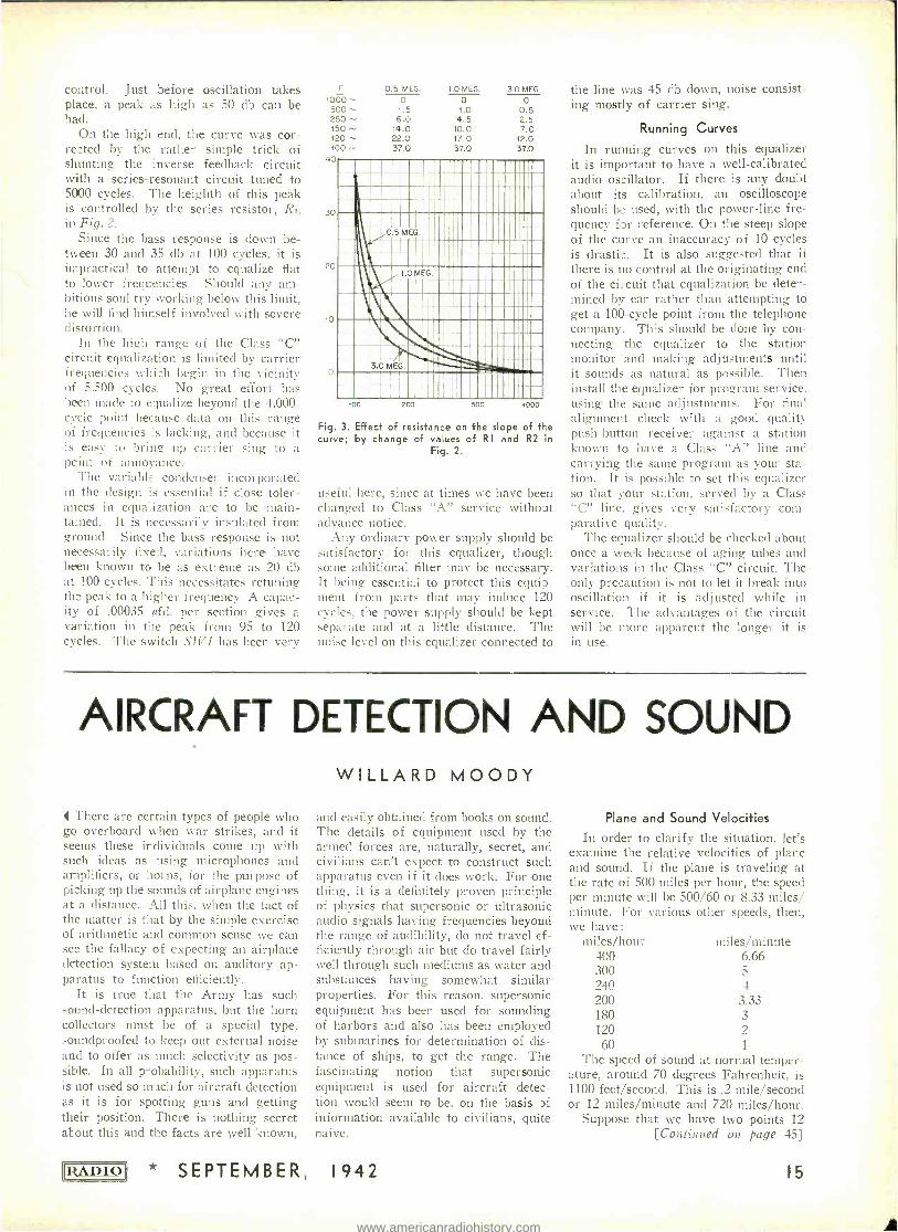
On the high end, the curve was cor- rected by the rather simple trick of shunting the inverse feedback circuit with a series -resonant circuit tuned to 5000 cycles. The heighth of this peak is controlled by the series resistor, R.,, in Fig. 2.
Since the bass response is down be- tween 30 and 35 db at 100 cycles, it is impractical to attempt to equalize flat to lower frequencies. Should any am- bitious soul try working below this limit, he will find himself involved with severe distortion.
In the high range of the Class "C" circuit equalization is limited by carrier frequencies which begin in the vicinity of 5,500 cycles. No great effort has been made to equalize beyond the 4,000 - cycle point because data on this range of frequencies is lacking, and because it is easy to bring up carrier sing to a peint of annoyance.
The variable condenser incorporated in the design Es essential if close toler- ances in equalization are to be main- tained. It is necessarily insulated from ground. Since the bass response is not necessarily fixed, variations here- have been known to he as extreme as 20 db at 100 cycles. This necessitates retuning the peak to a higher frequency. A capac- ity of .00035 pfd. per section gives a variation in the peak from 95 to 120 cycles. The switch SIh1 has been very
tono 0.5 MEG. 1.0 MEG. 3.0 MEG.
o o 500 1.5 1.0 0.5 250 ^- 6.0 4.5 2.5 150 ^- 14.0 10.0 7.0 120 ^- 22.0 17.0 12.0 loo 37.0 37.0 37.0
40
30
20
10
Fig. 3. Effect of resistance on the slope of the curve; by change of values of RI and R2 in
Fig. 2.
useful here, since at times we have been changed to Class "A" service witho_t advance notice.
Any ordinary power supply should be satisfactory for this equalizer, though some additional filter may be necessary. It being essential to protect this equip- ment from parts that may induce 120 cycles, the power supply should be kept separate and at a little distance. The noise level on this equalizer connected to
the line was 45 db down, noise consist- ing mostly of carrier sing.
Running Curves
In running curves on this equalizer it is important to have a well -calibrated audio oscillator. If there is any doubt about its calibration, an oscilloscope should be used, with the power -line fre- quency for reference. On the steep slope of the curve an inaccuracy of 10 cycles is drastic. It is also suggested that if there is no control at the originating end of the circuit that equalization be deter- mined by ear rather than attempting to get a 100 -cycle point from the telephone company. This should be clone by con- necting the equalizer to the station monitor and nuking adjustments until it sounds as natural as possible. Then install the equalizer for program service. using the same adjustments. For final alignment check with a good quality push -button receiver against a station known to have a Class "A" line and carrying the same program as your sta- tion. It is possible to set this equalizer so that your station, served by a Class "C" line. gives very satisfactory com- parative quality.
The equalizer should be checked about once a week because of aging tubes and variations in the Class "C" circuit. The only precaution is not to let it break into oscillation if it is adjusted while in service. The advantages of the circuit will be more apparent the longer it is in use.
AIRCRAFT DETECTION AND SOUND
I There are certain types of people who go overboard when war strikes, and it seems these individuals cone up with such ideas as using microphones and amplifiers, or iorns, for the purpose of picking up the sounds of airplane engines at a distance. All this, when the fact of the matter is fiat by the simple exercise of arithmetic and common sense we can see the fallacy of expecting an airplane detection system based on auditory ap- paratus to function efficiently.
It is true t :-ut the Army has such sound- detection apparatus, but the horn collectors must be of a special type, soundproofed to keep out external noise and to offer as much selectivity as pos- sible. In all p- obability, such apparatus is not used so mach for aircraft detection as it is for spotting guns and getting their position. There is nothing secret about this and the facts are well known,
IRA DIO * SEPTEMBER
WILLARD MOODY
and easily obtained from books on sound. The details of equipment used by the armed forces are, naturally, secret, and civilians can't expect to construct such apparatus even if it does work. For one thing, it is a definitely proven principle of physics that supersonic or ultrasonic audio signals having frequencies beyond the range of audibility, do not travel ef- ficiently through air but do travel fairly well through such mediums as water and substances having somewhat similar properties. For this reason, supersonic equipment has been used for sounding of harbors and also has been employed by submarines for determination of dis- tance of ships, to get the range. The fascinating notion that supersonic equipment is used for aircraft detec- tion would seem to be, on the basis of information available to civilians, quite naive.
1942
Plane and Sound Velocities
In order to clarify the situation, let's examine the relative velocities of plane and sound. If the plane is traveling at the rate of 500 miles per hour, the speed per minute will be 500 /60 or 8.33 miles/ minute. For various other speeds, then, we have:
miles /hour miles /minute 400 6.66 300 5
240 4 200 3.33 180 3
120 2 60 1
The speed of sound at normal temper- ature, around 70 degrees Fahrenheit, is 1100 feet /second. This is .2 mile /second or 12 miles /minute and 720 miles /hour.
Suppose that we have two points 12 [Continued on. page 45]
15
www.americanradiohistory.com
Q. & A. STUDY GUIDE
%ea, P4actice
215. What is meant by "counter c.m.f." in a d.c. motor?
It is the electromotive force induced in the motor armature by the conductors of the rotating motor armature cutting the lines of force of the field, similar to the armature in a generator. The induced voltage is opposite in polarity to the volt- age applied to the motor, and may be determined by operating the motor as a generator (at rated speed) and measur- ing the output with a voltmeter.
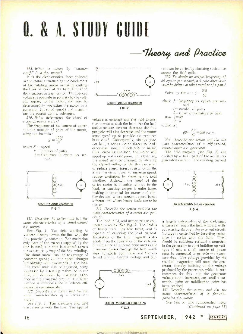
216. What determines the speed of a synchronous motor?
The frequency of the source of power and the number of poles of the motor, using the formula :
120f S= P
where S = speed P = number of poles f = frequency in cycles per sec-
ond.
SHUNT -WOUND D.C. MOTOR
FIG. 1
217. Describe the action and list the main characteristics of a shunt -wound d.c. motor.
See Fig. 1. The field winding is shunted directly across the line, with the flux practically constant. For excitation only part of the current supplied by the line is used, and this is shunted across the armature by way of the field winding. The shunt motor has the advantage of constant speed ; i.e., the speed changes but slightly with variations in the load. The speed may also be adjusted, being increased by inserting resistance in the field, and decreased by inserting resist- ance in the armature circuit. The latter method is inferior since it reduces effi- ciency of operation also.
218. Describe the action and list the main characteristics of a series d.c. motor.
See Fig. 2. The armature and field are in series with the line. The applied
16
SERIES-WOUND D.C. MOTOR
FIG. 2
voltage is constant and the field excita- tion increases with the load. As the load and armature current decrease the flux per pole will also decrease and the motor must speed up to provide the required back e.m.f. Consequently, always gear, not belt, a series motor direct to load ;
otherwise, should a belt slip or break, thus removing the load, the motor will speed up past a safe point. In regulating, the speed may be changed by altering the applied voltage or the flux per pole :
to reduce speed, insert resistance in the armature circuit, and to increase speed. reduce excitation by shunting the field winding. Although the speed of the series motor is unstable relative to the load, its starting torque is quite large, making it practical for cranes and sim- ilar devices, where constant speed is not a factor, but where heavy loads are to be moved.
219. Describe the action and list the main characteristics of a series d.c. gen- erator.
The load, field, and armature are con- nected in series. See Fig. 3. The field is of heavy wire, has few turns, and is capable of carrying the load current. Excitation of the field magnets is de- pendent on the resistance of the external circuit, since all current generated in the armature passes through the field wind- ings, to excite both these and the ex- ternal circuit. Output voltage and cur-
SERIES -WOUND D.C.GENERATOR
FIG. 3
rent can be varied by shunting resistance across the field coils.
220. To obtain an output frequency of 60 cycles per second, a 6 -pole alternator must be driven at what number of r.p.m. p
Solve by formula f PS 60
where f = frequency in cycles per sec- ond.
P= number of poles S= r.p.m. of armature or field.
thus f=60 P =6
to find S: 6S
60= 60 --=600 r.p.m.
221. Describe the action and list the main characteristics of a self -excited, shunt -wound d.c. generator.
The field magnets (see Fig. 4) are excited by a small part of the armature - generated current. The exciting current
SHUNT -WOUND D.C.GENERATOR
FIG.4
is largely independent of the load, since it passes through the field winding with- out passing through the external circuit. Voltage is controlled by inserting resist- ance in series with the field. There should be sufficient residual magnetism in the generator to start building up volt- age ; if not, a small source of power must be connected to provide the neces- sary flux. The voltage provided by the residual magnetism will start the gen- erator, thereby building up the voltage produced by the generator, which in turn increases the flux, and the generator voltage again increases, etc., until a sat- uration point or stabilization point has been reached. 222. Describe time action and list the main characteristics of a flat-com- pounded d.c. motor.
See Fig. 5. The compounded motor [Continued on page 35]
SEPTEMBER, 1942 RABIO
www.americanradiohistory.com
FROM BROADCAST TO TREVISION The Station Operator Is Confronted With New Problems and
Duties When He Takes On a Television Transmitter. The New
Operating Concepts Are Detailed Here.
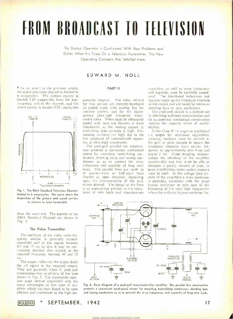
4 As we stated in the previous article, the entire television channel is limited to 6 megacycles. The picture carrier is located 1.25 megacycles from the low - fregt,ency end of the channel, and the sound carrier is located 5.75 megacycles
PICTU ^E CARRIER
SOUND CARRIER
.5 2 3 4
MEGACYCLES
w
5 1 6
- - 4 MC. - -- ELEVISION SIDEBAND
Fig. I. The RMA Standard Television Channel, limited to 6 megacycles. This curve shows the disposition of the picture and sound carriers
in relation to total bandwidth.
from the same end. The aspects of the RMA Standard Channel are shown in Fig. 1.
The Video Transmitter
The oscillator of the video radio -fre- gaency section is generally crystal - controlled and in the region between 6 5 and 12 mc so that it may be con- veniently doubled, then tripled, to the required frequency between 44 and 72 Inc.
The stages following the tripler build the r -f signal to the required output. They are generally Class C push -pull transmission -line amplifiers of the type shown in Fig. 2. The transmitter oper- ator must become acquainted with the many advantages of this type of am- plifier which has been found to be most efficient and convenient at the high fre-
IADIOJ
EDWARD M. NOLL
PART II
quencies required. The tubes utilized for this service are recently -developed air- cooled types with cooling fins for medium powers, and for the higher powers ultra -high frequency water - cooled tubes. Tubes must be adequately cooled with fans and blowers at these frequencies, as the heating caused -ay-
circulating tube currents is high. Cir- culating currents are high due to the low reactance of interelectrode capaci- ties at ultra -high frequencies.
The push -pull parallel -line constrnc- tion presents a convenient mechanical means for mounting neutralizing con- densers, shorting bars, and tuning con- densers so as to prevent the stray inductance and capacity of long wire leads. The parallel lines are made ip of quarter -wave or half -wave lines shorted or open circuited, depending upon the characteristics of the tank circuit desired. The design of the lines is an engineering project, as the induc- tance of tube leads and interelectrode
IN.
SHORTING BAR
DAMPING RESISTOR
capacities, as well as stray inductance and capacity, must be carefully consid- ered. The distributed inductance and capacity make up the frequency elements of the circuit and are tuned by means of shorting bars or disk condensers.
The push -pull circuit is a definite aid in obtaining sufficient neutralization and its symmetrical mechanical construction reduces the capacity effect of nearby objects.
In the Class B r -f stages or modulated r -f stages for television application. damping resistors must be utilized in the grid or plate circuits to insure flat frequency response from carrier fre- quency to approximately plus 4 mc and minus 2 mc. These damping resistors reduce the efficiency of the amplifier considerably and they must be able to dissipate a goodly amount of heat; in some installations, water -cooled resistors must be used. In the voltage feed cir- cuits of the amplifiers a mica condenser is generally paralleled with the usual bypass condenser to take care of the bypassing of the very high frequencies where the ordinary bypass condenser be-
FILAMENT VOLTAGE
o GR D
VOLTAGE
BY-PASS
TTMICA _L
PARASITIC RESISTORS
BY -PASS
MIGAN
Ou T.
PLATE VOLTAGE
T_ T
Fig. 2. Bask diagram of a push -pull transmission -line amplifier. The parallel line construction presents a convenient mechanical means for mounting neutralizing condensers, shorting bars and tuning condensers so as to prevent the stray inductance and capacity of long wire leads.
* SEPTEMBER, 1942 17
www.americanradiohistory.com
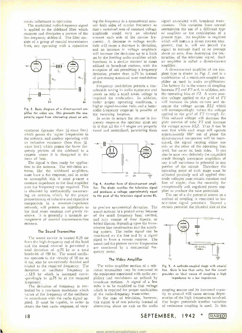
conies inductance in operation. The modulated radio -frequency signal
is applied to the sideband filter which removes and dissipates a portion of the low- frequency sideband. The filter con- sists of a group of coaxial transmission lines, one operating with a capacitive
vs
B+
Fig. 3. Basic diagram of a direct -current am-
plifier for video use. This prevents the one -
polarity signal from alternating about an axis.
reactance (greater than % -wave line) which passes the higher frequencies to the antenna, and another operating with an inductive reactance (less than %- wave line) which passes the lower fre- quency portion of the sideband to a resistor where it is dissipated in the form of heat.
The signal is then ready for applica- tion to the antenna. The television an- tenna, like the wideband amplifiers, must have a flat response, and in order to accomplish this it must present a constant impedance to the final amplifier over the frequency range required. This is obtained by mechanically construct- ing an antenna which, by the proper proportioning of inductive and capacitive components in a constant -impedance network, will present an impedance to the final stage constant and purely re- sistive. It is generally a turnstile ar- rangement of coaxial transmission -line sections.
The Sound Transmitter
The sound carrier is located 0.25 me from the high- frequency end of the band and the sound channel is permitted a total deviation of ±75 kc or a total bandwith of 150 kc. The sound oscilla- tor operates in the vicinity of 10 me so it can also be conveniently doubled and tripled to the required frequency. The deviation at oscillator frequency is +12.5 kc which is increased corre- spondingly to ±75 kc at the required frequency.
The deviation of frequency is con- trolled by a reactance modulator which varies at the frequency of the oscillator in accordance with the audio signal ap- plied. It must be capable, in order to obtain the best audio response, of vary-
18
ing the frequency in a symmetrical man- ner both sides of carrier frequency so that a sustained note of constant voltage amplitude would vary an identical amount each side of the carrier fre- quency. A decrease in voltage ampli- tude will cause a decrease in deviation, and an increase in voltage amplitude will increase the deviation up to a limit set by the limiting audio amplifier which functions in a similar manner to those utilized in broadcast stations, with the exception of not permitting a frequency deviation greater than ±75 kc instead of preventing sustained over -modulation peaks.
Frequency modulation permits a con- siderable saving in audio equipment and power as only a small auriio voltage is required for modulation. In addition, under proper operating conditions, a higher signal -to -noise ratio and a better audio -frequency response is possible at the receiving location.
In order to secure the utmost in fre- quency response the operator must see to it that all the r -f stages are properly tuned and neutralized, permitting them
C- C+
Fig. 4. Another form of direct -current ampli- fier. The diode rectifies the television signal
and produces a voltage approximately equal to the peak of the television signal across RL.
to produce symmetrical deviation. The sound antenna is a peaked array because of the small frequency band emitted, and may consist of four dipoles, or folded dipoles, depending upon the trans- mission line construction and the match- ing system. The audio signal can be monitored on the line and by a signal piped in from a remote receiver. The sound and the picture carrier frequencies are monitored by a commercial fre- quency meter.
The Video Amplifier
The video amplifier section of a tele- vision transmitter may be compared to the equipment associated with audio am- plifiers and modulators as utilized by broadcast stations. A signal of a few volts is to be amplified to that voltage which is required for proper modulation of the radio -frequency transmitter.
In the case of television, however, this signal is of one polarity instead of alternating about an axis as the audio
signal associated with broadcast trans- missions. This variation from normal necessitates the use of a different type of amplifier or the modification of a present type. An amplifier is required which will sustain a direct current corn - ponent ; that is, will not permit the signal to arrange itself as an average about an axis, thus destroying the con- struction of the television signal. Such an amplifier is called a direct -current amplifier.
A direct -current amplifier of the sim- plest type is shown in Fig. 3, and is a modification of a resistance -coupled am- plifier as used in audio amplification. The battery Ec is the means of coupling between V1 and V2 and, in addition, sets the operating bias of V2. A more posi- tive voltage applied to the grid of V.1
will increase its plate current and de- crease the voltage across RL1 which will correspondingly reduce the voltage applied to the grid of V2 through Ec. This reduced voltage will decrease the plate current of tube V2 and increase the voltage across RL2. Thus it can be seen that while each stage will operate approximately 180° out of phase the direct- current component will be main- tained, the signal varying either one side or the other of the operating bias level, but never on both sides. It can also be seen very definitely the magnified result through successive amplifiers of any small variations in potential in any portion of the circuit. Therefore the operating point of each stage must be adjusted precisely and all applied elec- trode voltages must remain constant and free of ripple ; thus the necessity for exceptionally well regulated power sup- plies to produce the tube potentials.
The use of a d -c potential source as a method of coupling is restricted to low television signal potentials. Beyond a certain potential the physical size of the
VNM O EP
CO-AXIAL CABLE
Ey
Fig. 5. A cathode -coupled stage with coaxial line. Gain is less than unity, but the circuit provides an ideal means of coupling a high
impedance to a low impedance.
coupling source and its increased capac- ity to ground will cause serious degen- eration of the high frequencies involved. For larger potentials another variation of resistance coupling is used. In this
SEPTEMBER, 1942 RADIO
www.americanradiohistory.com
system, as shown in Fig. 4, a diode rectifier and its load resistor is shunted across the output of the interstage coupling system. The diode rectifies the television signal and produces a voltage approximately equal to the peak of the television signal in its load resistor. The peak of the television signal, as you know, is the tip of the sychroniza- tion pulses and is of a constant ampli- tude with respect to the blanking level. The additive effect of this component and the proper amount of applied bias determines the operating point of tube 1'3.
Video Frequency Response
Thus far we have not mentioned the frequency response of the video ampli- fiers. We find that in order to meet the 4- megacycle requirements the plate load resistance of the video amplifier must be reduced to a very low value which correspondingly reduces the stage volt- age gain to a painfully low value. In addition, in many cases, tubes must be operated in parallel so as not to exceed Cie plate dissipation of a single tube operating at normal potentials with such a low plate load resistance, the low plate load resistance having caused a serious increase in plate current. Therefore, in video amplification we must utilize more stages to make up for the deficit in voltage gain per stage. Throughout all the video amplifiers precautions are taken by means of constant- impedance networks and compensation filters to prevent degeneration of high and low signal frequencies.
Another type of amplifier used in video amplification is the cathode - coupled stage, as shown in Fig. 5. The stage has a gain of less than unity, its advantage being in its ability to couple from a high impedance to a low im- pedance at approximately the same volt- age. The output is taken off the cathode at low impedance and since one side of the output is at ground potential and the other side requires no blocking con- denser, as no potential is applied to the cathode, it can be conveniently coupled to a coaxial line, thus preventing any high frequency degeneration associated with capacity coupling.
This system presents an ideal method of coupling the television signal of the order of a thousand volts as grid mod- ulation to the radio -frequency amplifier. The bias of the radio- frequency am- plifier is conveniently applied on the same line and by controlling this bias the radio -frequency output of the trans- mitter is controlled, and by operating the bias at a point where the r -f am- plifier plate current will saturate, the synchronization pulses can be flattened in case the ratio of picture to synchron- ization is too small.
RADIO
FREQUENCY MONITOR
INPUT SCOPE
PICTURE TRANSMITTER
OSCILLATOR BUFFER
DOUBLER TRIPLER
OUTPUT 'SCOPE
TRANSMISSION LINE
AMPLIFIERS
POWER SOURCES
COMPOSITE TELEVISION
SIGNAL FROM STUDIO
FREQUENCY MONITOR
REMOTE RECEIVER
VIDEO AMPLIFIERS
MODULATORS
PICTURE ANT.
SIDEBAND FILTER
R. F.
MODULATED AMPLIFIER
CLASS B RADIO
FREQ. AMP.
SWITCHING MONITORS
PICTURE AND OSCILLOSCOPE
SOUND TRANSMITTER
MODULATED OSCI LLATOR
AUDIO MONITOR
BUFFER DOUBLER TRIPLER
OUTPUT 'SCOPE
TRANSMISSION LINE
AMPLIFIERS
REMOTE RECEIVER
SOUND ANTENNA
AUDIO FROM STUDIO
LIMITER AMPLIFIER
REACTANCE MODULATOR
POWER SOURCES
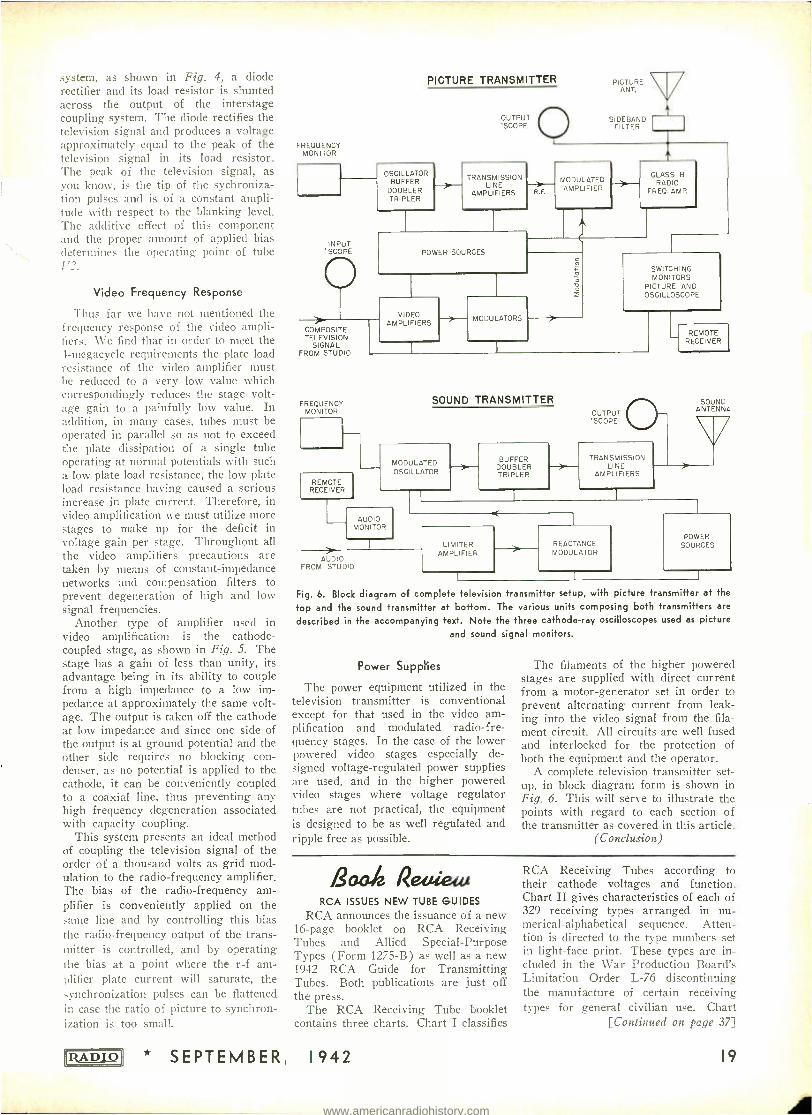
Fig. 6. Block diagram of complete television transmitter setup, with picture transmitter at the
top and the sound transmitter at bottom. The various units composing both transmitters are
described in the accompanying text. Note the three cathode -ray oscilloscopes used as picture
and sound signal monitors.
Power Supplies
The power equipment utilized in the television transmitter is conventional except for that used in the video am- plification and modulated radio -fre- quency stages. In the case of the lower powered video stages especially de- signed voltage -regulated power supplies are used, and in the higher powered video stages where voltage regulator tubes are not practical, the equipment is designed to be as well regulated and ripple free as possible.
The filaments of the higher powered stages are supplied with direct current from a motor -generator set in order to prevent alternating current from leak- ing into the video signal from the fila- ment circuit. All circuits are well fused and interlocked for the protection of both the equipment and the operator.
A complete television transmitter set- up, in block diagram form is shown in Fig. 6. This will serve to illustrate the points with regard to each section of the transmitter as covered in this article.
(Conclusion)
/2aa# Reffte w RCA ISSUES NEW TUBE GUIDES
RCA announces the issuance of a new 16 -page booklet on RCA Receiving Tubes and Allied Special- Purpose Types (Form 1275 -B) as well as a new 1942 RCA Guide for Transmitting Tubes. Both publications are just off the press.
The RCA Receiving Tube booklet contains three charts. Chart I classifies
* SEPTEMBER, 1942
RCA Receiving Tubes according to their cathode voltages and function. Chart II gives characteristics of each of 329 receiving types arranged in nu- merical- alphabetical sequence. Atten- tion is directed to the type numbers set in light -face print. These types are in- cluded in the War Production Board's Limitation Order L -76 discontinuing the manufacture of certain receiving types for general civilian use. Chart
[Continued on page 37]
19
www.americanradiohistory.com
NEMI-AUTOMATIC COIL WINDING
4 Unless a manufacturer of communica- tion equipment is producing quantative- ly, he is most likely facing the difficulty of getting finished coils and transform- ers. The reason is obvious, as the ex- isting facilities normally devoted to manufacturing these products are al- ready fully engaged to capacity by larg- er organizations.
However, a small manufacturer can overcome this handicap by setting up a coil department in his own plant. From the stand -point of economy and effici- ency, it is more advantageous for him to employ the semi -automatic process' rather than the automatic one. It is the purpose of this article to discuss the various elements involved in the semi- automatic process. The principle of op- eration of this method is the same as that of the automatic one; that is, the whole system is based on the application of correct tension, even layering of wire, and avoidance of straining of the wire while winding.
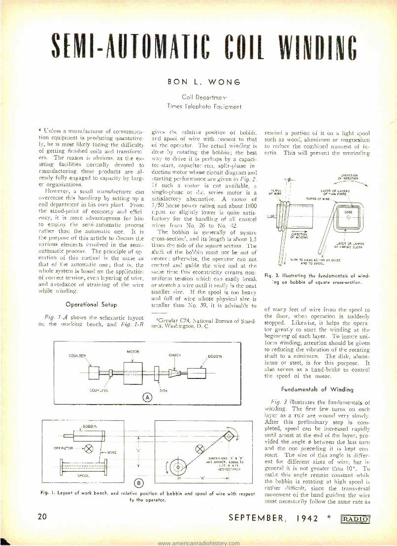
Operational Setup
Fig. 1 -A shows the schematic layout on the working bench, and Fig. 1 -B
BON L. WONG
Coil Department Times Telephoto Equipment
gives the relative position of bobbin and spool of wire with respect to that of the operator. The actual winding is done by rotating the bobbin ; the best way to drive it is perhaps by a capaci- tor- start, capacitor -run, split -phase in- duction motor whose circuit diagram and starting performance are given in Fig. 2. If such a motor is not available, a single -phase or d.c. series motor is a satisfactory alternative. A motor of 150 horse power rating and about 1800 r.p.m. or slightly lower is quite satis- factory for the handling of all enamel wires from No. 26 to No. 42.
The bobbin is generally of square cross -section', and its length is about 1.5 times the side of the square section. The shaft of the bobbin must not be out of center ; otherwise, the operator can not control and guide the wire and at the sanie time this eccentricity creates non- uniform tension which can easily break or stretch a wire until it really is the next smaller size. If the spool is too heavy and full of wire whose physical size is smaller than No. 39, it is advisable to
'Circular C74, National Bureau of Stand- ards, Washington, D. C.
COUNTER MOTOR
COUPLING
CHUCK
DISK
O
BOBBIN
/BOBBIN
OPERATOR - -
SPOOL
WIRE
DIMENSIONS "A" B "B' ARE APPROX. EQUAL TO
t FT. B 4 FT. RESPECTIVELY
Fig. I. Layout of work bench, and relative position of bobbin and spool of wire with respect to the operator.
20
rewind a portion of it on a light spool such as wood, aluminum or magnesium to reduce the combined moment of in- ertia. This will prevent the unwinding
TURNS l
OF WIRE
DIRECTION OF ROTATION
LAYER OR AL YERS OF THIN FIBRE
TURNS OF WIRE
-- OF WINDING G
LAYER OR LAYERS OF EMPIRE CLOTH
WIRE TO HAND ACTING AS GUIDE AND TO SPOOL
Fig. 3. Illustrating the fundamentals of wind- ing on bobbin of square cross -section.
of many feet of wire from the spool to the floor, when operation is suddenly stopped. Likewise, it helps the opera- tor greatly to start the winding at the beginning of each layer. To insure uni- form winding, attention should be given to reducing the vibration of the rotating shaft to a minimum. The disk, alumi- inum or steel, is for this purpose. It also serves as a hand -brake to control the speed of the motor.
Fundamentals of Winding
Fig. 3 illustrates the fundamentals of winding. The first few turns on each layer as a rule are wound very slowly. After this preliminary step is com- pleted, speed can be increased rapidly until amost at the end of the layer, pro- vided the angle 0 between the last turn and the one preceding it is kept con- stant. The size of this angle is differ- ent for different sizes of wire, but in general it is not greater than 10 °. To make this angle remain constant while the bobbin is rotating at high speed is rather difficult, since the transversal movement of the hand guiding the wire must necessarily follow the same rate as
SEPTEMBER, 1942 (12ADIOJ
www.americanradiohistory.com
the number of turns being wound on the bobbin. Again, this rate is not fixed for all sizes of wire. However, once this technique is acquired through expe- rience, the actual time consumed for winding a given coil is almost insignif- icant in comparison with that in feeding interleaving paper between layers, mak- ing adequate insulation between wind- ings and to the core, and soldering con- necting leads.
The usual method of construction of transformers used in push -pull ampli- fiers and full -wave rectifiers is known as the "unbalanced" secondary wind- ing. As shown in Fig. 4 -A, the tap is taken out at the middle of the secondary. Obviously, the half of the secondary next to the core has a higher shunting opacity and lower resistance than does tae other half, but likewise possesses a lower leakage inductance with respect t) the primary winding. As a result, the voltage delivered by the two halves cf the secondary winding are not the same. This is not satisfactory if high r uality of operation is necessary. A better way of construction is shown in Fig. 4 -B. The primary is wound in the usual manner, but the halves of the sec- ondary must be dealt with separately, as indicated in the sketch.
Wire Guiding
Since crossing turns must be avoided, the position o.2, the hand guiding the wire is important. It is generally held at a distance of 5" to 7" from the bobbin. In the event that this distance is exceeded, the wire will vibrate, and crossed turns and unequal pitch of turns become in- evitable. Consequently, the operator must stop winding in order to unwind the unwanted turns. The speed of wind- ing a coil depends on three factors : (1) on adequate supply of tools and materials easily accessible to the hand, correct bench height; and comfortable seating ;
(2) speed of motor or bobbin, controlled through a variable -speed switch by the :oot of the operator, and (3) the rate of transversal movement of the wire or perfect coordination between hand and foot.
UNBALANCED SECONDARY
Si 1
52 ]
BALANCED SECONDARY
O Fig. 4. Unbalanced and balanced secondary
windings in push -pull transformers.
IRADIOI
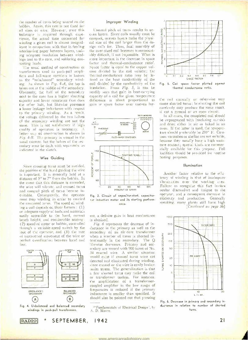
Improper Winding
Unequal pitch of turns results in un- even layers. Since coils usually must be compact, uneven layers make the physi- cal size of the coil larger than the de- sign calls for. Thus, final assembly of the over -sized coil becomes insurmount- ably difficult, if not impossible. What is more important is the decrease in space factor and thermal- conductance ratio'. Space factor is equal to the copper vol- ume divided by the coil volume; the thermal- conductance ratio may be de- fined as the heat conductivity of the coil divided by the conductivity of the insulation. From Fig. 5, it can be readily seen that gain in heat -carrying capacity of a coil for given temperature difference is about proportional to gain in space factor over uneven lay-
o- A.C.
SUPPLY
RHEOSTAT
AUXILIARY-, WINDING
MAIN WINDING
140
a
g 120
o Z w 100
w a
80
OILED -PAPER CONDENSER
ROTOR
STARTING TORQUE
20 40 60 80 PERCENT OF SPEED
100
Fig. 2. Circuit of capacitor -start, capacitor - run induction motor and its starting perform-
ance.
ers, a definite gain in heat conductance is obtained.
Fig. 6 represents the decrease of in- ductance in the primary as well as the secondary of an air -core transformer when a number of turns is shorted in- tentionally in the secondary. The Q likewise decreases. Primary and sec- ondary are wound with 900 turns of No. 34 enamel wire. A similar situation would exist if crossed turns were not detected and eliminated during winding, since enamel on the wire is easily broken under stress. The generalization is that a few shorted turns may make the coil or transformer useless. For instance. the amplification of a transformer - coupled amplifier in the low range of frequencies is reduced if the primary inductance is smaller than specified. It should also be pointed out that pressing
'Fundamentals of Electrical Design'', by A. D. Moore.
* SEPTEMBER, 1942
7
06 Q cc w5 Z a cFj 4
Z 0
2 w
2
4
o 0 01 0.2 03 04 05 06
SPACE FACTOR
0.7
Fig. 5. Coil space factor plotted against
thermal conductance ratio.
the coil manually or otherwise may cause shorted turns ; laminating the coil carelessly may produce the same result, if not a ground or an open circuit.
In all cases, the completed coil should be impregnated with insulating varnish and dried either in air or baked in an oven. If the latter is used, the tempera- ture should preferably be 210° F. Com- mon varnishes or shellac are not suitable, because they usually have a high mois- ture content ; special kinds are commer- cially available for this purpose. Full facilities should be provided for routine testing purposes.
Illumination
Another factor relative to the effic- iency of winding is that of inadequate illumination over the working area. Failure to recognize this fact invites ocular discomfort and fatigue to the operator, and a consequent decrease in efficiency and production. Generally speaking, many plants still have high
[Continued on page 36]
1000
500
200
100
50
20
10
10
L in mh.
20
Fig. 6. Decrease in primary and secondary in-
ductance in relation to number of shorted
turns.
21
www.americanradiohistory.com

AUDIO BRIDGE OSCIRATOR
IthA Bui 11-9frt Cali/via/44
4 Frequency enters into most electrical formulae, and a variable- frequency source makes it possible to take measure- ments at several different frequencies. This is necessary in some applications and a calibrated source is necessary in any case.
The variable frequency audio oscil- lator described here contains a 60 -cycle built -in calibrator which makes it self calibrating after it is once properly ad- justed. This may be accomplished by comparing it with another oscillator of known accuracy, or it may be calibrated by using frequency charts and a piano as a comparison frequency source.
The oscillator uses a variation of the Wein bridge for control of frequency, and has a range from 20 to 15,000 cycles, depending on the transformers used.
Construction
The components are mounted in a wood case eight inches square. A metal
A. K.McLAREN
case would be better but is not a neces- sity.
In the panel view the 2E5 electron - ray tube is in the upper left corner, and directly below it the cathode rheostat (R1) adjustment for the oscillator tube. The shaft is sawed off short and a screw- driver slot sawed in the end of shaft. In center is main dial. At the upper right is the frequency range switch. At right center are the output pin jacks, and at lower right the a.f. output control R15.
The dual potentiometer R4 -R5, of 10,000 ohms each unit, are not only of the same resistance but must have the same taper. If a dual potentiometer of this type is not procurable, use separate, linear wire -wound units ganged to- gether, and adjust each one to 5,000 ohms at center before locking. The ones used in this unit were ganged by mounting them on small metal strips and locking them together by means of an old style dual tuning unit.
The 3 -to -1 audio -frequency trans-
22
Panel view of the va- riable- frequency os-
cillator, made up from inexpensive spare parts. The cen- ter control operates the dual potentio- meter R4 -R5 which is a part of the
bridge circuit.
former T1 should be a good quality unit for best low- frequency response. The transformers are connected so as to give both positive and negative feedback. Transformer T1 furnishes the positive feedback and should be connected so that oscillation can be established before the other parts are connected. The other parts may then be assembled.
It may be necessary to reverse either the primary or secondary connections of transformer T2 to get negative feedback. Rotation of the controls will have little effect on the tuning if these connections are not properly made.
The cathode resistor RI controls the feedback and should be advanced just far enough to provide satisfactory oscil- lation. The main dial should be rotated to see that oscillation continues at all settings of the controls.
The resistors R3 and R6, and the con- densers C3 to C8 used in the feedback control circuit, must have close toler- ances. The dual potentiometer R4 -R5 must also maintain similar values of resistance at all points of rotation. Other components are not critical as to values.
The transformer T1 should have a high- impedance primary -the higher the better. The one used in this unit had a 15,000 -ohm primary and was found to work much better than other trans- formers with lower impedance primary windings. The primary winding of T1 should be connected in the grid circuit of the oscillator tube.
Transformer T2 is a tube -to -line transformer with a ratio of 2,500- to 500 ohms. The 500 -ohm side is con- nected to the bridge network. A 2,000 - to 500 -ohm transformer would be better if it can be obtained.
The resistor R2 is used to insure oscillation at the lower frequencies and may have a somewhat different value for different tubes and transformers.
60 -Cycle Calibrator
As stated before, the instrument may be calibrated by using frequency charts and a piano, or by means of a calibrated
SEPTEMBER, 1942 'RADIO'
www.americanradiohistory.com
oscillator, but care must be taken in the latter case to see that the fundamental is used and not a harmonic. Frequencies above the range of a piano, however, must be obtained by using harmonics.
The calibration can also be clone by f.rst finding the 60 -cycle point and then using the 60- cycle calibrator to find the other points which will appear every 60 cycles. The 2E5 tube produces an opening or closing pattern when off resonance with the 60 -cycle line voltage. Whether it appears to close or open de-
- pends on which side of resonance the frequency happens to be. At resonance t:ìe pattern is stationary. The harmonics of the oscillator also show up as pat- terns between 60 -cycle points, but the 60 -cycle points give a clearer or more vivid pattern and are easily distin- guished from the harmonics. At ex- tremely high frequencies the patterns become so close together that it is diffi- cult to see them, but they can be used. Moreover, at the higher frequencies the even harmonics appear as multiple pat- terns but only show up at the 60 -cycle points and therefore will cause no con- fusion.
The accuracy of the 60 -cycle points will vary from a fraction of a cycle at 60 cycles, to 50 cycles at 6,000 cycles. The error is multiplied by the number of the harmonic being used. Thus if the line current is off one -half cycle, the error would be multiplied by 100 at 6,000 cycles. This gives an error of 50 cycles. Most power stations now maintain their frequency within a frac- tion of a cycle, and some have automatic frequency controls and hold to even closer tolerances.
Audio Amplifier
The audio amplifier operates Class A
56 OSCILLATOR
2
A A
and is directly coupled to the feedback network to obviate the frequency Cis - crimination of coupling circuits. The excitation should not ne great enough to drive the amplifier grid positive, and :he cathode bypass condenser C12 should be 16 pfd. or larger in order to obtain a3e- quate response at the low frequencies.
An output transformer with several different output impedances could be in- corporated in the unit in place of :he
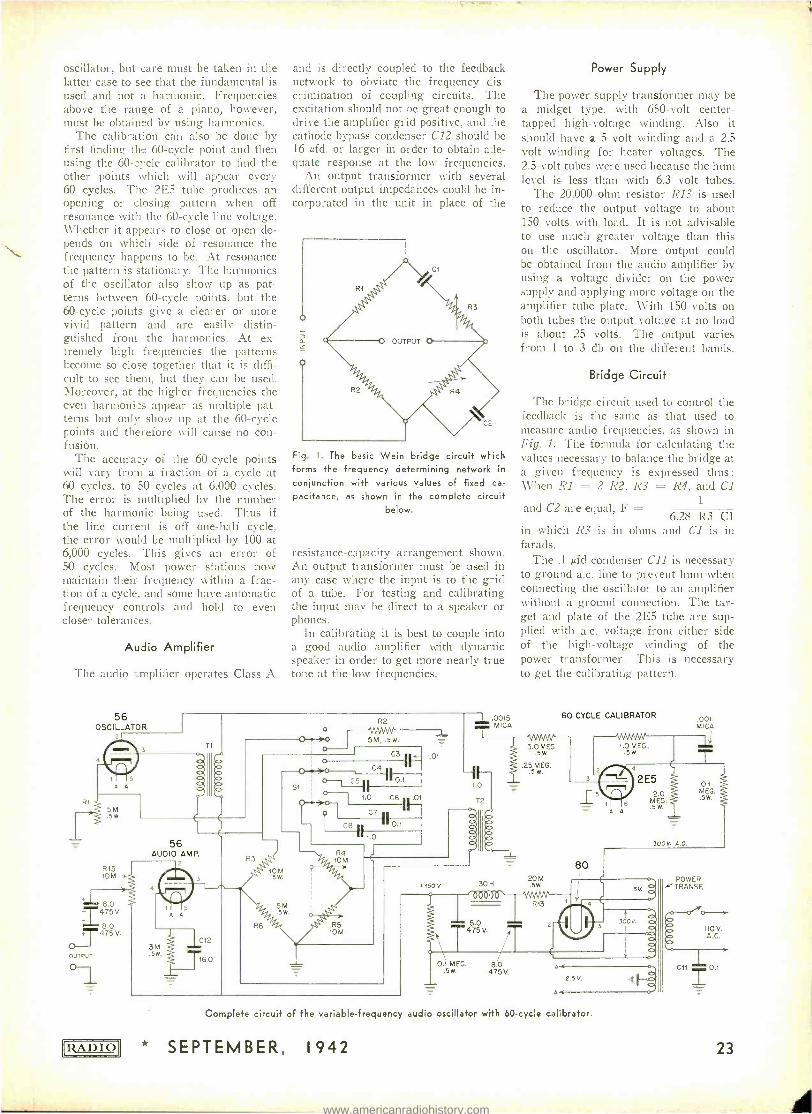
Fig. I. The bask Wein bridge circuit wi-ich forms the frequency determining network in
conjunction with various values of fixed ca-
pacitance, as shown in the complete circuit below.
resistance- capacity arrangement shown. An output transformer must be used in any case where the input is to the grid of a tube. For testing and calibrating the input may be direct to a speaker or phones.
In calibrating it is best to couple into a good audio amplifier with dynamic speaker in order to get more nearly true tone at the low frequencies.
Ri 5M .Sw
R15 10M -v.
8.0
I475V 8.0 +T475 V.
OUTPUT
RADIO
o O.>o
i o o G3 Ir-.01
O } >0 C4 -11 Ì1 R2
5M, .5w.
SI
56 AUDIO AMP.
0 .01 O0-4--).0
1.0 G6 l 1
_107
.5w
.0015 MICA
Power Supply
The power supply transformer may be a midget type, with 650 -volt center - tapped high -voltage winding. Also it should have a 5 volt winding and a 2.5 volt winding for heater voltages. The 2.5 -volt tubes were used because the hum level is less than with 6.3 volt tubes.
The 20,000 ohm resistor R13 is used to reduce the output voltage to about 150 volts with load. It is not advisable to use much greater voltage than this on the oscillator. More output could be obtained from the audio amplifier by using a voltage divider on the power supply and applying more voltage on the amplifier tube plate. With 150 volts on both tubes the output voltage at no load is about 25 volts. The output varies from 1 to 3 db on the different bands.
Bridge Circuit
The bridge circuit used to control the feedback is the same as that used to measure audio frequencies, as shown in Fig. 1. The formula for calculating the values necessary to balance the bridge at a given frequency is expressed thus: When RI = 2 R2, R3 = R4, and Cl
1
6.28 R3 Cl in which R3 is in ohms and Cl is in farads.
The .1 ,ufd condenser C11 is necessary to ground a.c. line to prevent hum when connecting the oscillator to an amplifier without a ground connection. The tar- get and plate of the 2E5 tube are sup- plied with a.c. voltage from either side of the high -voltage winding of the power transformer. This is necessary to get the calibrating pattern.
and C2 are equal, F =
+150 v 30 H
3.0 MEG. .5W.
.25 MEG. .5 w.
20M .5W.
60 CYCLE CALIBRATOR
3
1.0 MEG.
4
.00t MICA
0.1 MEG. .5W.
2E5 5
A A
2.0 MEG. .5W.
300V. A.C.
0.1 MEG. 8.0 .5w. 475V.
A
A<
2.5 V.
Complete circuit of the variable- frequency audio oscillator with 60 -cycle calibrator.
* SEPTEMBER, 1942
-
POWER TRANSF.
o Y 110V. A.C.
C11 0.1
23
www.americanradiohistory.com
New Products
NEW CELLULOSE ACETATE INSULATED BOBBIN COIL FORM
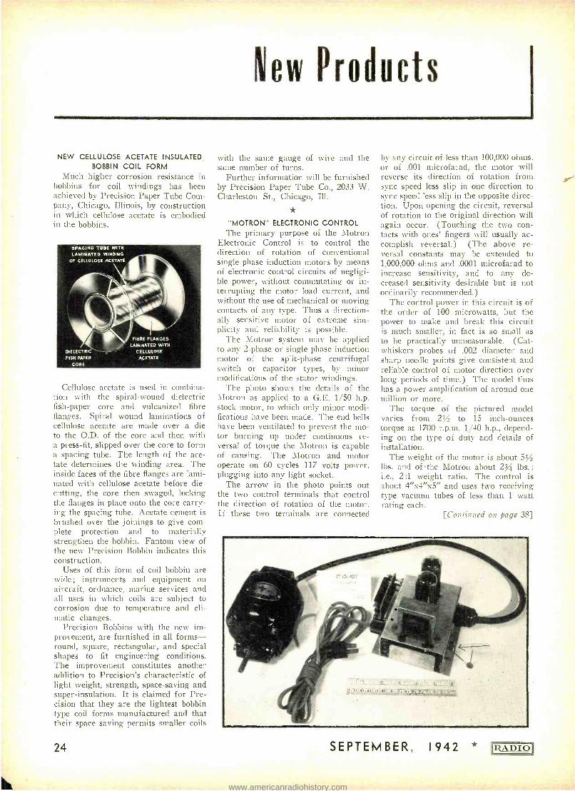
Much higher corrosion resistance in bobbins for coil windings has been achieved by Precision Paper Tube Com- pany, Chicago, Illinois, by construction in which cellulose acetate is embodied in the bobbins.
SPACING TUNE WITH
LAMINATED WINDING
OF CELLULOSE ACETATE
DIE LECTRIC` FISH PAPER
CORE
FIBRE FLANGES
LAMINATED WITH CELLULOSE ACETATE
Cellulose acetate is used in combina- tion with the spiral -wound dielectric fish -paper core and vulcanized fibre flanges. Spiral wound laminations of cellulose acetate are made over a die to the O.D. of the core and then with a press -fit, slipped over the core to form a spacing tube. The length of the ace- tate determines the winding area. The inside faces of the fibre flanges are lami- nated with cellulose acetate before die - cutting, the core then swaged, locking the flanges in place onto the core carry- ing the spacing tube. Acetate cement is brushed over the joinings to give com- plete protection and to materially strengthen the bobbin. Fantom view of the new Precision Bobbin indicates this construction.
Uses of this forni of coil bobbin are wide; instruments and equipment on aircraft, ordnance, marine services and all uses in which coils are subject to corrosion due to temperature and cli- matic changes.
Precision Bobbins with the new im- provement, are furnished in all forms - round, square, rectangular, and special shapes to fit engineering conditions. The improvement constitutes another addition to Precision's characteristic of light weight, strength, space- saving and super -insulation. It is claimed for Pre- cision that they are the lightest bobbin type coil forms manufactured and that their space saving permits smaller coils
24
with the same gauge of wire and the same number of turns.
Further information will be furnished by Precision Paper Tube Co., 2033 W. Charleston St., Chicago, Ill.
"MOTRON" ELECTRONIC CONTROL The primary purpose of the Motron
Electronic Control is to control the direction of rotation of conventional single -phase induction motors by means of electronic control circuits of negligi- ble power, without commutating or in- terrupting the motor load current, and without the use of mechanical or moving contacts of any type. Thus a direction- ally sensitive motor of extreme sim- plicity and reliability is possible.
The Motron system may be applied to any 2 -phase or single -phase induction motor of the split -phase centrifugal switch or capacitor types, by minor modifications of the stator windings.
The photo shows the details of the Motron as applied to a G.E. 1/50 h.p. stock motor, to which only minor modi- fications have been made. The end bells have been ventilated to prevent the mo- tor burning up under continuous re- versal of torque the Motron is capable of causing. The Motron and motor operate on 60 cycles 117 volts power, plugging into any light socket.
The arrow in the photo points out the two control terminals that control the direction of rotation of the motor. If these two terminals are connected
by any circuit of less than 100,000 ohms, or of .001 microfarad, the motor will reverse its direction of rotation from sync speed less slip in one direction to sync speed less slip in the opposite direc- tion. Upon opening the circuit, reversal of rotation to the original direction will again occur. (Touching the two con- tacts with ones' fingers will usually ac- complish reversal.) (The above re- versal constants may be extended to 1,000,000 ohms and .0001 microfarad to increase sensitivity, and to any de- creased sensitivity desirable but is not ordinarily recommended.)
The control power in this circuit is of the order of 100 microwatts, but the power to make and break this circuit is much smaller, in fact is so small as to be practically unmeasurable. (Cat - whiskers probes of .002 diameter and sharp needle points give consistent and reliable control of motor direction over long periods of time.) The model thus has a power amplification of around one million or more.
The torque of the pictured model varies from 2/ to 15 inch -ounces torque at 1700 r.p.m. 1/40 h.p., depend- ing on the type of duty and details of installation.
The weight of the motor is about 5/ lbs. and of the Motron about 23/4 lbs.; i.e., 2 :1 weight ratio. The control is about 4 "x4 "x5" and uses two receiving type vacuum tubes of less than 1 watt rating each.
[Continnned on page 38]
SEPTEMBER, 1942 RADIO
www.americanradiohistory.com
RADIO- ELECTRONIC BIBLIOGRAPHY
Engineering, Vol. 2, No. 3, March, 1935, Page 18.
New Design Program Amplifier for Broadcast Stations -L. W. Barnett - Communication & Broadcast Engineer- ing, Vol. 2, No. 7, July, 1935, Page 10.
High Frequency in Audio Frequency Amplifiers - E. K. Sandeman - The Wireless Engineer, Vol. 2, No. 130, July, 1934, Page 351. The Amplification of Program Tran- sients in Radio Receivers -G. Builder - Journal Institute Engineers of Australia, Vol. 6, No. 10, October, 1934, Page 325. Noise as a Limiting Factor in Amplifier Design -The Marconi Review, Septem- ber 10, 1933, Page 5.
The Design of Low -Frequency Trans- former- Coupled Amplifiers -W. S. Nortley -The Marconi Review, No. 45, Nov. & Dec., 1933, Page 25. Distortion Cancellation in Audio Ampli- gers-W. Baggly- Experimental Wire- less & Wireless Engineer, Vol. 10, Aug- ust, 1933, Page 413.
A Method of Measuring Distortion in Audio Frequency Amplifiers -W. Tuttle -Journal SMPE, February, 1932, Page 199.
A New Method of Testing the Distor- tion in Audio Frequency Amplifiers - H. J. Reich -Proceedings IRE, Vol. 21, No. 3, March, 1931, Page 401. Analysis of Distortion in Resistance Coupled Amplifiers -E. B. Moullin- Experimental Wireless & Wireless En- gineer, March, 1931, Page 118.
Distortionless Amplifiers of Transients -A. K. Oatley- Experimental Wireless & Wireless Engineer, June, 1931, Page 307.
Distortion in Volume Characteristics - E. V. Lucas -Experimental Wireless & Wireless Engineer, November, 1931, Page 595.
Tuned Radio Frequency Amplifiers -L. Cohen -Electronics, April, 1930, Page 21.
Measurements of Harmonic Distortion in Vacuum Tube Circuits -D. F. Schmit and A. Stinchfield -Electronics, May, 1930, Page 79.
A New Power Amplifier -L. Thomson -Proceedings SMPE, November, 1930, Page 602. Analysis of Uniform Radio Frequency Amplification - E. A. Uehling - Elec- tronics, December, 1930, Page 414. New Power Amplifier with Positive Grid Bias -L. Thomson -Electronics, June, 1930, Page 139.
The 245 Push -Pull Radio and Phono- graph Amplifiers -K. Riley -Radio En- gineer, May, 1929.
Voltage Surges in Audio Frequency Ap- paratus-J. Fisher- Proceedings IRE, Vol. 19, No. 5, May, 1929.
Notes on Distortion in Audio Frequency Amplifiers - E. Nelson - OST, April, 1929.
RADIO
Amplifier for Condenser Transmitter - H. C. Curl -Bell Lab. Record, Vol. 6, No. 4, June, 1928, Page 329.
Performance of Amplifiers -A. Thomas -Journal AIEE, February, 1926.
Transformer Coupled Audio Frequency Amplifiers - A. W. Saunders - Radio Broadcast, October, 1927.
Radio Frequency Amplifiers -W. James - Wireless World, July 13, 1927.
Common Impedance in Amplifier Power Supply -S. E. Anderson -Proceedings IRE, Vol. 17, No. 12, December, 1927.
A Compact Direct -Current Amplifier (No. 6031A) -H. C. Curl -Bell Lab. Record, Vol. 5, No. 2, October, 1927, Page 46.
Modulation in Vacuum Tubes Used as Amplifiers -B. Peterson and H. P. Evans -Bell System Technical Journal, Vol. 6, 1927, Page 442.
Application of Vacuum Tube Amplifiers to Submarine Telegraph Cables -A. M. Curtis -Bell System Technical Journal, Vol. 6, 1927, Page 425.
Load Carrying Capacity of Amplifiers - F. C. Willis and L. E. Melhuish -Bell System Technical Journal, Vol. 5, No. 10. October, 1926.
Operation of Thermionic Vacuum Tube Circuits -F. B. Llewellyn -Bell System Technical Journal, Vol. 5, No. 7, July, 1926.
Selecting an Audio Frequency Ampli - fier-D. F. Whiting -Bell Lab. Records, Vol. 2, No. 4, June, 1926, Page 145.
Output Characteristics of Amplifier Tubes -J. C. Warner and A. V. Laugh- ren- Proceedings IRE, Vol. 16, No. 12, December, 1926, Page 735.
Design of Non -distorting Power Ampli- fiers - E. W. Kellogg - Proceedings AIEE, May, 1925.
High Frequency Amplifiers -H. T. Friis and A. G. Jensen -Bell System Technical Journal, Vol. 3, No. 2, 1924, Page 181.
Development of Electron Tube Ampli - fiers-E. W. Lowell -Journal AIEE, July, 1922.
Notes on the Design of Resistance Ca- pacity Coupled Amplifiers -S. Harris - Proceedings IRE, Vol. 2, No. 12, De- cember, 1921, Page 759.
A New System of Short Wave Amplifi- cation-E. H. Armstrong- Proceedings IRE, February, 1921, Page 3.
The Operational Characteristics of Thermionic Amplifiers -S. Ballentine- Proceedings IRE, April, 1919, Page 129.
A Theoretical Study of the Three Ele- ment Vacuum Tube -J. R. Carson - Proceedings 1 RE, Vol. 7, No. 4, April, 1919, Page 187.
A Magnetic Amplifier for Radio Teleph- onv-E. F. W. Alexanderson and S. P. Nixdorff - Proceedings IRE, April, 1916. Page 101.
* SEPTEMBER, 1942
DETECTION
Some Notes on Diode Detection -A. Priesman - Communications, Vol. 20, No. 8, August, 1940, Page 18.
Properties of Biased Diode Rectifiers - F. C. Williams and A. Fairweather - Wireless Engineer, July, 1939, Page 330. Diode Operating Conditions -W. P. N. Court -Wireless Engineer, Vol. 16, No. 194, November, 1939, Page 548.
New Detector Circuit -W. N. Weeden -Wireless World, January 1, 1937, Page 6.
Free Oscillations of Resonant Circuit Loaded by Diode Rectifier -F. C. Wil- liams- Wireless Engineer, Vol. 14, Au- gust 3, 1937, Page 403.
The Detection of Single Side -band Waves -C. B. Aiken -Communication & Broadcast Engineering, Vol. 3, No. 2, February, 1936, Page 5.
Improving Diode Detector Perform- ance -Radio Engineering, Vol. 16, No. 3, March, 1936, Page 18.
Non -Radiating Super- Regenerative De- tector-W. E. Bonham -Radio Engi- neering, Vol. 16, No. 7, July, 1936, Page 23.
The 6F7 Used as an Amplifier and Sec- ond Detector -J. R. Nelson -Radio En- gineering, Vol. 15, No. 7, July, 1935. Page 12.
Notes on the Theory of Diode Rectifica- tion-J. Marique- Wireless Engineer, Vol. 12, No. 136, January, 1935, Page 17.
The Detector Load -W. F. Cope - Wireless Engineer, Vol. 12, No. 144. September, 1935, Page 478. Notes on S.G. Pentode Detector -F. R. W. Strafford- Wireless Engineer, Vol. 11, No. 132, August, 1934, Page 484.
Straight Line Detection with Diode - R. Roberts and F. C. Williams- Journ,sl AIEE, Vol. 75, No. 453, September, 1934, Page 379. Linear Detector Distortion -K. W. Jar - vis- Électronics, December, 1934, Page 386.
On Conversion Detectors -M. J. O. Strutt -Proceedings IRE, Vol. 22, No. 8, August, 1974, Page 181.
Some Applications of an ALC. Valve Bridge -M. Reed -Wireless Engineer, Vol. 11, April, 1934, Page 175, No. 127.
Positive Grid Valve as a Detector -H. E. Hollmann- Wireless Engineer, Vol. 11, No. 129, June, 1934, Page 309. Linear Rectification -- R. Lambert - Electronics, January, 1934, Page 21. The Mode of Action of Diode Detection -R. Urtel -Telef. Zeit., Vol. 14, No. 14, 1933, Page 30.
Modulation Products in a Power Modu- lator-A. G. Tynan -Proceedings IRE, Vol. 21, August, 1933, Page 1203.
Rectification Analysis -M. J. O. Strutt -Zeit fur Hochfrequen.s., Vol. 42, 1933, Page 206.
27
www.americanradiohistory.com
RADIO -ELECTRONIC BIBLIOGRAPHY
The Double Diode Triode -C. N. Smith and J. Steward -Wireless World, Vol. 32, 1933, Page 355. The Hexode Vacuum Tube -H. A. Wheeler -Radio Engineering, Vol. 13, No. 4, Page 12, 1933. Problems in Selective Reception -M. V. Callendar -Proceedings IRE, Vol. 20. No. 9, September, 1932, Page 1427. Recent Trends in Receiver Tube Design -D. F. Schmit, J. C. Warner, and E. W. Ritter -Proceedings IRE, Vol. 20, August, 1932, Page 1247. Detection of Modulated Waves -G. Varret -l'Onde Electrique, Vol. 2, 1932, Page 315. A New Valve Characteristic -P. K. Turner-Wireless Engineer, Vol. 9, Page 384, 1932. Notes on the Wunderlich Tube -F. E. Termann - Electronics, April, 1932, Page 148. Calculation of Detection Performance for Large Signals -H. Woods- Physics, April, 1932, Page 225. The Graphical Solution of Detector Problems -H. H. Lucas -Wireless En- gineer & Experimental Wireless, April, 1932, Page 202. The Mutual Interference Wireless Sig- nal vs. Simultaneous Detection -E. V. Appleton- Wireless Engineer & Ex- perimental Wireless, Vol. 9, No. 102, March, 1932, Page 136. Apparent Demodulation -E. Mallett- Wireless Engineer & Experimental Wireless, Vol. 9, No. 104, May, 1932, Page 248. The Graphical Solution of Detector Problems -G. S. C. Lucas -Wireless Engineer & Experimental Wireless, No. 104,. May, 1932, Page 253. The Detector -W. B. Lewis -Wireless Engineer & Experimental Wireless, Vol. 9, No. 108, September, 1932, Page 487. The S.G. Valve as a Frequency Changer in the Superheterodyne - E. L. C. White- Wireless Engineer, Vol. 9, Page. 618; 1932. Overload Limit Extension in 4 Element Detectors -J. W. Farnham- Electron- ics, December, 1931, Page 228. Bias Detector Overload -J. R. Nelson - Radio Engineering, March, 1931, Page 21. Detection of Two Modulated Waves Which Differ Slightly in Carrier Fre- quency - C. B. Aiken - Proceedings IRE, Vol. 19, January, 1931, Page 120. Test Procedure for Detectors with a Re- sistance Coupled Output -G. F. Robin- son- Proceedings IRE, Vol. 19, May, 1931, Page 806, No. 5.
Small Signal Detection -E. L. Chaffee -Electronics, May, 1931, Page 641. Quality Detectors -H. Greenwood and W. H. Preston -Wireless Engineer & Experimental Wireless, December, 1931, Page 648. Power Grid Detection -W. T. Cocking - Wireless World, May 7, 1930.
28
Grid or Plate Circuit Detector -L. H. Martin -Radio News, August, 1930, Page 125. Optimum Characteristics of Vacuum Tube Detectors -H. A. Robinson - OST, August, 1930, Page 23. Linear Detection Heterodyne Signal - F. E. Terman -Electronics, October, 1930, Page 386. General Analysis of Amplification & Detection by Thermionic Valves -N. Vermes- Annalen. der Physik, Vol. 4, 1930, Page 943. Rectification Characteristics & Detection Diagrams -R. Ruedy- Physical Review, Vol. 35, Page 129, 1930. Some Properties of Grid Leak Power Detection -F. E. Terman and N. R. Morgan- Proceedings IRE, December, 1930, Vol. 18, Page 2160. Detection at High Signal Voltage -S. Ballantine- Proceedings IRE, Vol. 17, July, 1929, Page 1153. Grid Leak vs. Bias Detection -W. Stinchfield -Radio Broadcast, October, 1929, Page 351. Rectification of Radio Signals by Tube Containing Alkili Vapor -W. L. Kind - gon- Charlton -Physical Review, June, 1929, Page 998. Calculating Detector Output - J. C. Stinchfield -Radio Broadcast, August, 1929, Page 239. Grid Leak or Anode Bend -W. James - Amateur fireless, July 6, 1929. Grid Leak Power Detection -F. E. Ter - man -Radio Broadcast, April, 1929, Page 382. Getting the Most out of Detector -F. E. Terman -Radio Broadcast, May, 1929. Detection by Grid Receiver with High Vacuum Triode -S. Ballantine -Pro- ceedings IRE, May, 1928. Grid Current Modulation -E. Peterson and C. R. Keith -Bell System Technical Journal, January, 1928. Rectification of Small R. F. Potentials with the Triode -F. M. Colebrook - Experimental Wireless, January, 1928. Grid Current Modulation -C. R. Keith -Radio Engineering, November, 1928. Principle of Grid Leak Condenser De- tector - F. E. Terman - Proceedings IRE, October, 1928. Detection with 4 Electrode Tubes -J. R. Nelson -Proceedings IRE, September, 1928. Note on Detection by Grid Condenser Leak -H. Robert - Proceedings IRE, January, 1028. Grid Circuit Detection Distortion -J. R. Nelson -Radio Engineering, December, 1928, Page 19.
Behavior of Alkali Vapor Detector Tubes - L. F. Brown - Proceedings IRE, January, 1927. Radio Translated for Experimentals- C. W. Rados -QST, April, 1927. Detection of Small Signals -E. L. Chaf- fee- Proceedings IRE, February, 1927.
Detection -J. C. Smith -Proceedings IRE, October, 1926. Theory of Detection in a High Vacuum Thermionic Tube -L. P. Smith -Pro- ccedings IRE, October, 1926, Page 649. Alkali Detector Tubes -H. H. Brown and W. Knipp - Journal AIEE, Janu- ary, 1924. Detecting Characteristics of Electron Tubes -H. M. Freeman -Proceedings IRE, October, 1925, Page 611. New Applications of the Dosion Detec- tor-H. P. Donle- Proceedings IRE, April, 1924, Page 159. A New Non-Interfering Detector -H. P. Donle- Proceedings IRE, April. 1923, Page 97. Mathematical Treatment of Rectifica- tion Phenomena -D. C. Prince -Pro- ceedings IRE, October, 1922, Page 393. The Dynatron Detector -A New Heter- odyne Receiver for Continuous and Modulated Waves -A. W. Hull, E. F. Hennelly and F. R. Elder -Proceedings IRE, October, 1922, Page 320. On the Detecting Efficiency of the Ther- mionic Detector -H. J. Van der Bill - Proceedings IRE, December, 1919, Page 603. A New Method of Using Contact Detec- tors in Radio Measurements -L. W. Austin- Proceedings IRE, June, 1919. Page 257. Quantitative Relations in Detector Cir- cuits -B. Liebowitz- Proceedings IRE, February, 1917, Page 33. The Audion- Detector and Amplifier -L. De Forest -Proceedings IRE, January, 1914, Page 15.
OSCILLATORS
The Locked -in Oscillator -S. Vyard and W. H. Eccles- Wireless Engineer, Vol. 18, No. 208, January, 1941, Page 2. The Ultra Short Wave Generator with Phase-Focusing -Ludi-Hochf : Tech. i!. Elek: akus., Vol. 56, No. 2, August, 1940, Page 60. Low Loss Hollow Space Circuits for Oscillation Generation in the Deci- metric -Wave Region by Velocity Modu- lation-R. H. Varian -ETZ, Vol. 61, No. 31, August 1, 1940, Page 722. Production of Ultra High Frequency Radio Waves by Electronic Oscillations -S. S. Danerjee and A. S. Rao -Indian Journal of Physics, Vol. 14, Part 2, April, 1940. The Neuman's Oscillator -T. R. Rehfish and W. T. Cocking- Wireless Engineer, Vol. 46, No. 12, October, 1940, Page 442. Tuned -Grid Tuned -Plate Oscillator -I. E. Mourontseff -Communications, Vol. 20, No. 8, August, 1940, Page 7. Frequency Controlled Oscillators -S. Sabaroff- Communications, No. 2, Vol. 19, February, 1939, Page 7. The Transitron Oscillator -C. Brunetti -Proceedings IRE, Vol. 27, No. 2, Feb- ruary, 1939, Page 88.
[Continued on page 30]
SEPTEMBER, 1942 RADIO
www.americanradiohistory.com
¡IZADIO
i'Ol/'LL OPEN YDl/R ¡YES WHEN yousFF irr ECD/OPNØNE FC ->
Echophone Model EC -i 6 tubes, 3 bands. Tunes from 550 kc. to 30 mc. Beat frequency oscillator. Bandspread logging scale. Self -con- tained speaker. Electrical bandspread on all bands. AC /DC. 115 -=25 volts. ECHOPHONE RADIO CO., 201 EAST 26TH ST., CHICAGO, :LLINOIS
* SEPTEMBER, 1942 29
www.americanradiohistory.com

RADIO -ELECTRONIC BIBLIOGRAPHY
An Improvement in Constant -Frequency Oscillators -G. F. Lampkin-Proceed- ings IRE, Vol. 27, No. 3, March, 1939, Page 199. Oscillations in Certain Nonlinear Driven Systems - D. L. Herr - Proceedings IRE, Vol. 27, No. 7, July, 1939, Page 396. Fractional -Frequency Generators Utiliz- ing Regenerative Modulation -R. J. Miller - Proceedings IRE, Vol. 27, No. 7, July, 1939, Page 446.
Relations Existing Between Voltage Im- pulses of Exponential Form and the Re- sponse of an Oscillating Circuit -R. Lambert -Proceedings IRE, Vol. 26, No. 3, March, 1938, Page 372.
The Bridge -Stabilized Oscillator -L. A. Meacham -Proceedings IRE, Vol. 26, No. 10, October, 1938, Page 1278.
Stabilized Feedback Oscillators -G. H. Stevenson -Bell System Technical Jour- nal, Vol. 17, July, 1938, Page 458.
The Bridge Stabilized Oscillator -L. A. Meacham -Bell System Technical Jour- nal, Vol. 17, October, 1938, Page 574.
Application of the Autosynchronized Oscillator to Frequency Demodulation - J. R. Woodyard -Proceedings IRE, Vol. 25, No. 5, May, 1937, Page 612.
A Thermal Method for Measuring Effi- ciencies of Ultra -High Frequencies Ap- plied to the Magnetron Oscillator -H. W. Kohler -Proceedings IRE, Vol. 25, No. 11, November, 1937, Page 1381.
A Low Distortion Audio -Frequency Os- cillator-H. J. Reich -Proceedings IRE, Vol. 25, No. 11, November, 1937, Page 1387. Magnetic Generation of a Group of Har- monics-E. Peterson, J. M. Manley and L. R. Wrathall -Bell System Technical Journal, Vol. 16, October, 1937, Page 437.
Oscillations in Systems with Non -Linear Reactance -R. F. L. Hartley -Bell Sys- tem Technical Journal, July, 1936, Vol. 15, Page 424.
Oscillations in an Electromechanical System -L. W. Hussey and L. R. Wrat- hall -Bell System Technical Journal, Vol. 15, July, 1936, Page 441.
Filter Coupled Low Discharge Oscilla- tor-W. E. Cock -Radio Engineering, Vol. 16, No. 5, May, 1936, Page 18.
Frequency Modulated Generators -A. W. Barber -Radio Engineering, Vol. 16, No. 11, November, 1936, Page 14.
Oscillator Padding -H. Roder -Radio Engineering, Vol. 15, No. 3, March, 1935, Page 7.
Simplified Oscillators -Radio Engineer- ing, Vol. 15, No. 3, March, 1935, Page 17.
The Barkhausen Oscillator -F. B. Llew- ellyn -Radio Engineering, Vol. 15, No. 10, October, 1935, Page 12.
Constant Frequency Oscillators -F. B. Llewellyn -Bell System Technical Jour- nal, Vol. 11, January, 1932, Page 67.
30
The Design of Radio -Frequency Signal Generators -J. R. Bird -Proceedings IRE, Vol. 19, No. 3, March, 1931, Page 438.
Oscillations in the Circuit of a Strongly Damped Triode -F. Vecchiacchi-Pro - ceedings IRE, Vol. 19, No. 5, May, 1931, Page 856.
Operating Frequency of Regenerative Oscillatory Systems -H. Benioff -Pro- ceedings IRE, Vol. 19, No. 7, July, 1931, Page 1274.
Constant Frequency Oscillators -F. B. Llewellyn- Proceedings IRE, Vol. 19, No. 12, December, 1931, Page 2063.
A Recent Development in Vacuum Tube Oscillator Circuits -J. B. Dow -Pro- ceedings IRE, Vol. 19, No. 12, Decem- ber, 1931, Page 2095.
A New Treatment of Electron Tube Os- cillators with Feedback Coupling -C. K. Jen- Proceedings IRE, Vol. 19, No. 12, December, 1931, Page 2109.
The Magnetron Amplifier and Power Oscillator -F. R. Elder- Proceedings IRE, April, 1925, Page 159.
Generation of Polyphase Oscillations by Means of Vacuum Tubes -R. Mesny- Proceedzngs IRE, August, 1925, Page 471.
A Graphical Method of Analysis of Vacuum Tube Oscillators -J. W. Hor- ton -Bell System Technical Journal, Vol. 3, No. 3, 1924, Page 508.
A High Efficiency Vacuum Tube Oscil- lating Circuit -D. C. Prince and F. B. Vogdes - Proceedings IRE, October, 1924, Page 623.
Vacuum Tubes as Power Oscillators, Part 1 -D. C. Prince - Proceedings IRE, June, 1923, Page 275. Vacuum Tubes as Power Oscillators, Part 2 -D. C. Prince -Proceedings IRE, August, 1923, Page 405.
Vacuum Tubes as Power Oscillators, Part 3-D. C. Prince -Proceedings IRE, October, 1923, Page 527.
A Study of the Oscillations Occurring in the Circuits of the Pliotron -J. E. Ives and C. N. Hickman -Proceedings IRE, April, 1922, Page 115.
A Method for Testing and Rating Elec- -iron Tube Generators -L. M. Hull - Proceedings IRE, October, 1922, Page 373.
The Dynatron, a Vacuum Tube Possess- ing Negative Resistance -A. W. Hull - Proceedings IRE, February, 1918, Page 5.
Oscillating Audion Circuits - L. A. Hazeltine - Proceedings IRE, April, 1918, Page 63.
The Resistance of the Spark and Its Effect on the Oscillations of Electrical Oscillators -J. S. Stone -Proceedings IRE, December, 1914, Page 307.
The Production of High Frequency Oscillations -H. Shoemaker- Proceed- ings IRE, Vol. 1, No. 4, September, 1909.
COILS, CHOKES & TRANSFORMERS
A.C. Impedance of Chokes and Trans - formers-T. J. Rehfisch and H. T. Dusnoid -Wireless Engineer, Vol. 18, No. 214, July, 1941, Page 266. Design of A.F. Input and Intervalve Transformer -J. G. Story- Wireless Engineer, Vol. 15, No. 173, February, 1938, Page 69. A Graphical Design of an Intermediate - Frequency Transformer with Variable Selectivity -C. Baranovsky and A. Jen- kins- Proceedings IRE, Vol. 25, No. 3, March, 1937, Page 340. The Temperature Coefficient of Induc- tance- J. Grosszkowski -Proceedings IRE, Vol. 25, No. 4, April, 1937, Page 448. On the Optimum Length for Transmis- sion Lines Used as Circuit Elements - B. Salzberg- Proceedings IRE, Vol. 25, No. 12, December, 1937, Page 1561. Design and Application of Power Trans - formers-I. A. Mitchell- Communica- tion & Broadcast Engineering, Vol. 3, No. 3, March, 1936, Page 15. Transformer Design -L. A. Kelly -Ra- dio Engineering, Vol. 15, No. 2, Febru- ary, 1935, Page 16. Radio Engineering, Vol. 14, No. 12, December, 1934, Page 7. Transformers for Class B Modulation - M. J. Oman -Communication & Broad- cast Engineering, Vol. 1, No. 1, October, 1934, Page 14.
Design of Wide Range Audio Trans - formers-I. A. Mitchell -Radio Engi- neering, Vol. 14, No. 4, May, 1934, Page 22. Transformers for Class B Modulation - J. Kunz -Radio Engineering, Vol. 14, No. 7, July, 1934, Page 13.
Auto Transformer Circuit Analysis - W. J. Creamer -Radio Engineering, Vol. 14, No. 7, July, 1934, Page 16.
Iron Core High Frequency Transform - ers-H. A. Ford -Radio Engineering, Vol. 14, No. 11, November, 1934, Page 17.
Supplementary Note to the "Study of the High- Frequency Resistance of Sin- gle -Layer Coils " -A. J. Palermo and F. W. Grover -Proceedings IRE, Vol. 19, No. 7, July, 1931, Page 1278.
Output Transformer Response -F. E. Terman and R. E. Ingebetsen -Elec- tronics, January, 1936, Page 30.
Transformer Coupling Circuits for High- Frequency Amplifiers --A. J. Christopher - Bell System Technical Journal, Vol. 11, October, 1932, Page 608. Dutput Transformer Design -H. C. Hitchcock and I. C. Osborn- Electron- ics, November, 1930 ; Electronics, De- cember, 1930. Treatment of A.F. Transformer Lines - H. A. Nasen -Radio Engineer, July, 1929. A.F. Transformers -W. Klev and K. Shirley- Journal AIEE, Dec. 1939.
[Continued on page 32]
SEPTEMBER, 1942 RADIO!
www.americanradiohistory.com
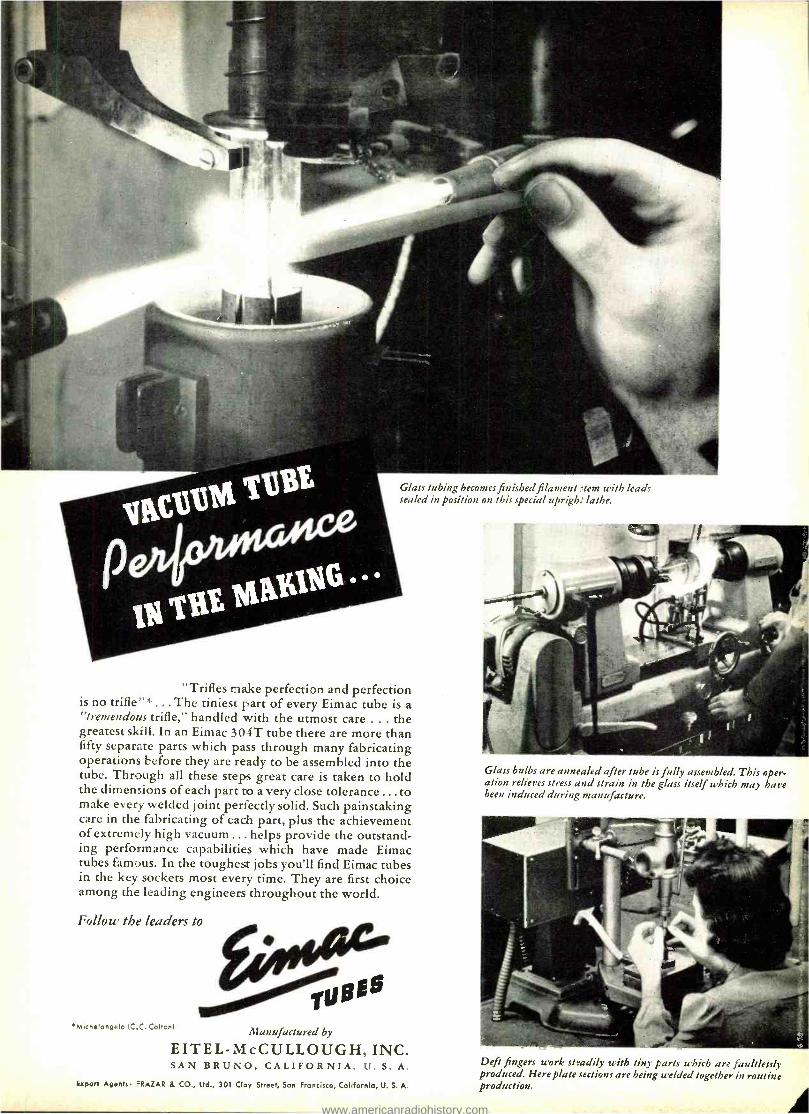
Glass tubing becomes finished filament stem with lead, sealed in position on this special upright lathe.
"Trifles make perfection and perfection is no trifle"* ... The tiniest part of every Eimac tube is a "tremendous trifle," handled with the utmost care ... the greatest skill. In an Eimac 304T tube there are more than fifty separate parts which pass through many fabricating operations before they are ready to be assembled into the tube. Through all these steps great care is taken to hold the dimensions of each part to a very close tolerance ... to make every welded joint perfectly solid. Such painstaking care in the fabricating of each part, plus the achievement of extremely high vacuum ... helps provide the outstand- ing performance capabilities which have made Eimac tubes famous. In the toughest jobs you'll find Eimac tubes in the key sockets most every time. They are first choice among the leading engineers throughout the world.
Follow the leaders to
6E6
*Michelangelo (C.C. Colton/ Manufactured by
EITEL -McCULLOUGH, INC. SAN BRUNO, CALIFORNIA, U. S. A.
ixport Agents: FRAZAR & CO., Ltd., 301 Clay Street, Son Francisco, California, U. S. A.
Glass bulbs are annealed after tube is fully assembled. This oper- ation relieves stress and strain in the glass itself which may have been induced during manufacture.
Deft fingers work steadily with tiny parts which are faultlessly produced. Here plate sections are being welded together in routine production.
www.americanradiohistory.com
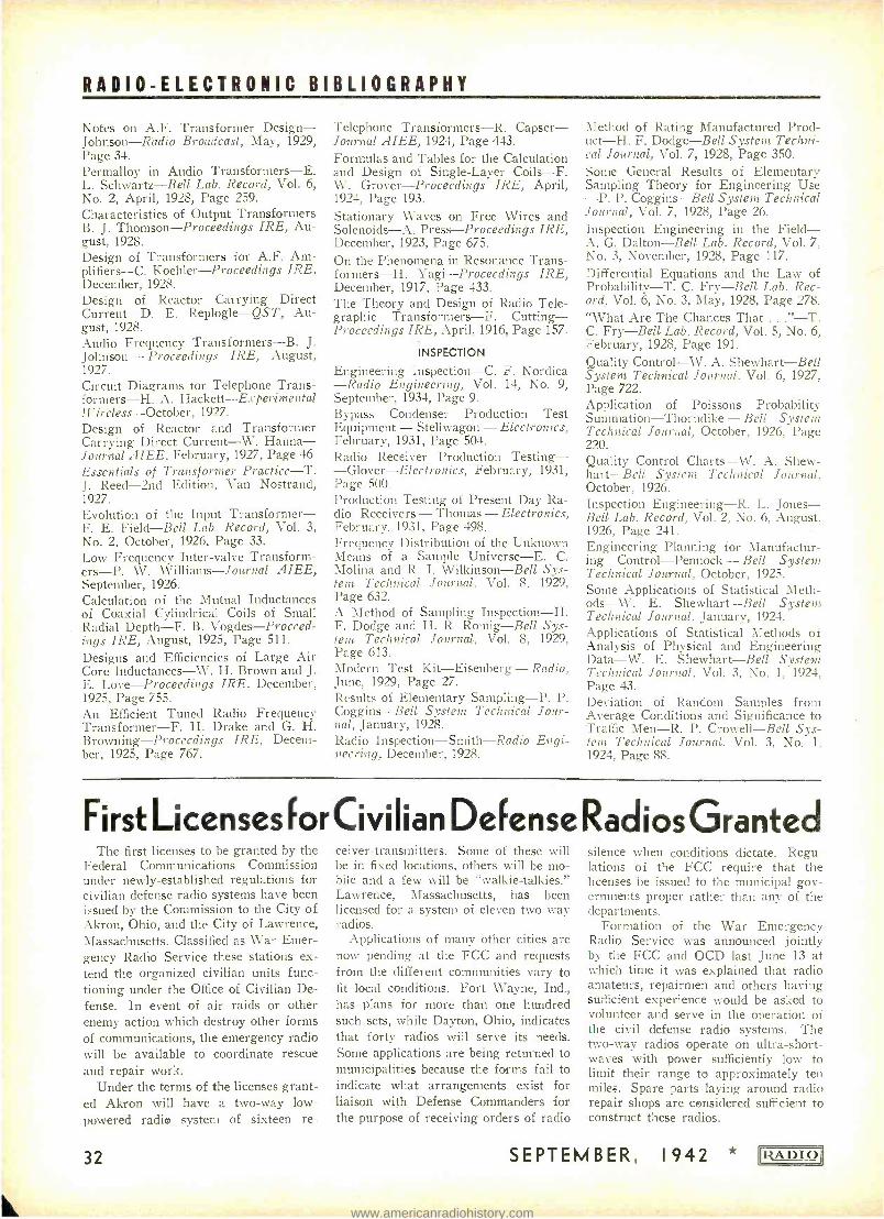
RADIO- ELECTRONIC BIBLIOGRAPHY
Notes on A.F. Transformer Design - Johnson -Radio Broadcast, May, 1929, Page 34. Permalloy in Audio Transformers -E. L. Schwartz -Bell Lab. Record, Vol. 6, No. 2, April, 1928, Page 259. Characteristics of Output Transformers B. J. Thomson -Proceedings IRE, Au- gust, 1928. Design of Transformers for A.F. Am- plifiers-C. Koehler -Proceedings IRE, December, 1928. Design of Reactor Carrying Direct Current -D. E. Replogle -QST, Au- gust, 1928. Audio Frequency Transformers -B. J. Johnson - Proceedings IRE, August, 1927. Circuit Diagrams for Telephone Trans - formers-H. A. Hackett- Experimental 1f'ireless- October, 1927.
Design of Reactor and Transformer Carrying Direct Current -W. Hanna - Journal AIEE, February, 1927, Page 46.
Essentials of Transformer Practice -T. J. Reed -2nd Edition, Van Nostrand, 1927. Evolution of the Input Transformer - F. E. Field -Bell Lab. Record, Vol. 3, No. 2, October, 1926, Page 33.
Low Frequency Inter -valve Transform - ers-P. W. Williams -Journal AIEE, September, 1926. Calculation of the Mutual Inductances of Coaxial Cylindrical Coils of Small Radial Depth -F. B. Vogdes- Proceed- ings IRE, August, 1925, Page 511.
Designs and Efficiencies of Large Air Core Inductances -W. H. Brown and J. E. Love -Proceedings IRE, December, 1925, Page 755. An Efficient Tuned Radio Frequency Transformer -F. H. Drake and G. H. Browning -Proceedings IRE, Decem- ber, 1925, Page 767.
Telephone Transformers -R. Capser- Journal AIEE, 1924, Page 443.
Formulas and Tables for the Calculation and Design of Single -Layer Coils -F. W. Grover -Proceedings IRE, April, 1924, Page 193.
Stationary Waves on Free Wires and Solenoids -A. Press -Proceedings IRE, December, 1923, Page 675.
On the Phenomena in Resonance Trans - formers-H. Yagi -Proceedings IRE, December, 1917, Page 433. The Theory and Design of Radio Tele- graphic Transformers -F. Cutting - Proceedings IRE, April, 1916, Page 157.
INSPECTION
Engineering Inspection -C. F. Nordica -Radio Engineering, Vol. 14, No. 9, September, 1934, Page 9. Bypass Condenser Production Test Equipment - Stellwagon - Electronics, February, 1931, Page 504. Radio Receiver Production Testing- -Glover -Electronics, February, 1931, Page 500. Production Testing of Present Day Ra- dio Receivers - Thomas - Electronics, February, 1931, Page 498. Frequency Distribution of the Unknown Means of a Sample Universe -E. C. 'Molina and R. I. Wilkinson -Bell Sys - tem Technical Journal, Vol. 8. 1929, Page 632. A Method of Sampling Inspection -H. F. Dodge and H. R. Romig -Bell Sys- tem Technical Journal, Vol. 8, 1929, Page 613. Modern Test Kit -Eisenberg - Radio, June, 1929, Page 27. Results of Elementary Sampling -P. P. Coggins -Bell System Technical Jour - nal, January, 1928. Radio Inspection- Smith -Radio Engi- neering, December, 1928.
Method of Rating Manufactured Prod - uct-H. F. Dodge -Bell System Techni- cal Journal, Vol. 7, 1928, Page 350.
Some General Results of Elementary Sampling Theory for Engineering Use -P. P. Coggins -Bell System Technical Journal, Vol. 7, 1928, Page 26.
Inspection Engineering in the Field - A. G. Dalton -Bell Lab. Record, Vol. 7, No. 3, November, 1928, Page 117.
Differential Equations and the Law of Probability -T. C. Fry -Bell Lab. Rec- ord, Vol. 6, No. 3, May, 1928, Page 278. "What Are The Chances That ... " -T. C. Fry -Bell Lab. Record, Vol. 5, No. 6, February, 1928, Page 191.
Quality Control -W. A. Shewhart -Bell System Technical Journal, Vol. 6, 1927, Page 722. Application of Poissons Probability Summation -Thorndike - Bell System Technical Journal, October, 1926, Page 220. Quality Control Charts -W. A. Shew- hart -Bell System Technical Journal, October, 1926. Inspection Engineering-R. L. Jones - Bell Lab. Record, Vol. 2, No. 6, August, 1926, Page 241. Engineering Planning for Manufactur- ing Control- Pennock - Bell System Technical Journal, October, 1925. Some Applications of Statistical Meth - ods-W. E. Shewhart -Bell System Technical Journal, January, 1924. Applications of Statistical Methods of Analysis of Physical and Engineering Data -W. E. Shewhart -Bell System Technical Journal, Vol. 3, No. 1, 1924, Page 43. Deviation of Random Samples from Average Conditions and Significance to Traffic Men -R. P. Crowell -Bell Sys- tem Technical Journal, Vol. 3, No. 1, 1924, Page 88.
First LicensesforCivilian DeFense RadiosGranted The first licenses to be granted by the
Federal Communications Commission under newly -established regulations for civilian defense radio systems have been issued by the Commission to the City of Akron, Ohio, and the City of Lawrence, Massachusetts. Classified as War Emer- gency Radio Service these stations ex- tend the organized civilian units func- tioning under the Office of Civilian De- fense. In event of air raids or other enemy action which destroy other forms of communications, the emergency radio will be available to coordinate rescue and repair work.
Under the terms of the licenses grant- ed Akron will have a two -way low - powered radio system of sixteen re-
32
ceiver- transmitters. Some of these will be in fixed locations, others will be mo- hile and a few will be "walkie- talkies." Lawrence, Massachusetts, has been licensed for a system of eleven two -way radios.
Applications of many other cities are now pending at the FCC and requests from the different communities vary to fit local conditions. Fort Wayne, Ind., has plans for more than one hundred such sets, while Dayton, Ohio, indicates that forty radios will serve its needs. Some applications are being returned to municipalities because the forms fail to indicate what arrangements exist for liaison with Defense Commanders for the purpose of receiving orders of radio
silence when conditions dictate. Regu- lations of the FCC require that the licenses be issued to the municipal gov- ernments proper rather than any of the departments.
Formation of the War Emergency Radio Service was announced jointly by the FCC and OCD last June 13 at which time it was explained that radio amateurs, repairmen and others having sufficient experience would be asked to volunteer and serve in the operation of the civil defense radio systems. The two -way radios operate on ultra- short- waves with power sufficiently low to limit their range to approximately ten miles. Spare parts laying around radio repair shops are considered sufficient to construct these radios.
SEPTEMBER, 1942 IIZADIO1
www.americanradiohistory.com
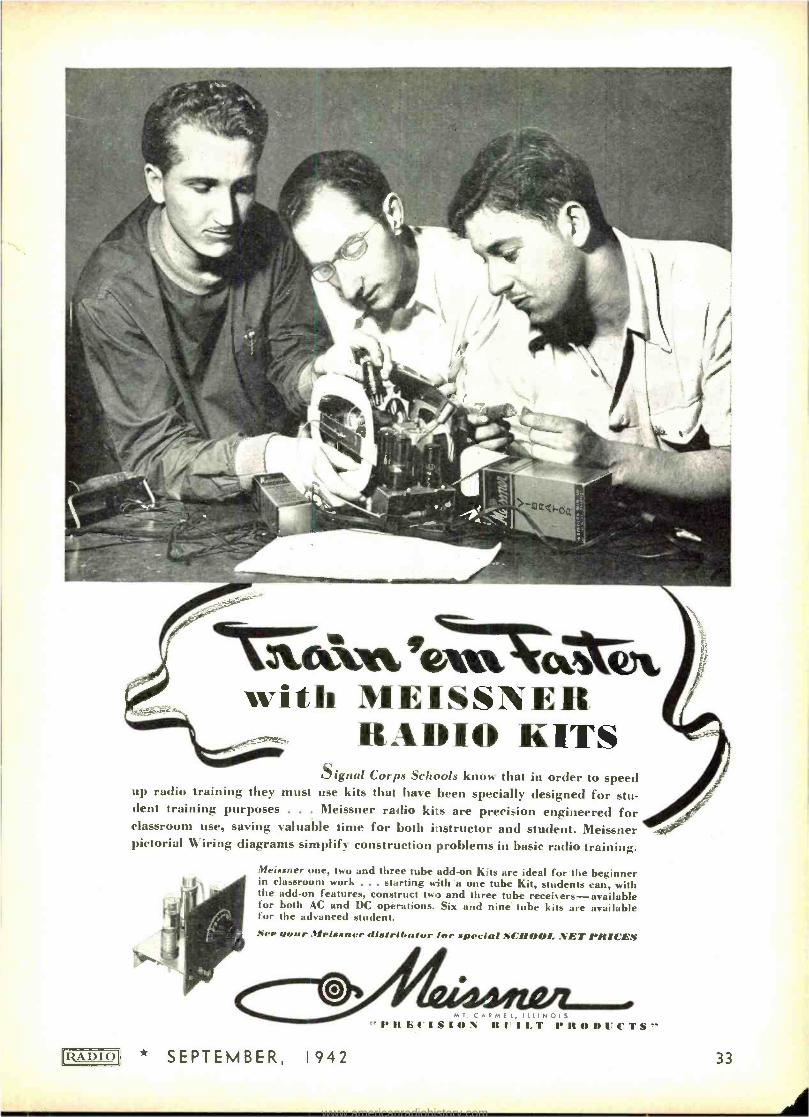
`k- i! 1. rim with MEISSNER
RADIO KITS
[RADIO
Signal Corps Schools know that in order to speed up radio training they must use kits that have been specially designed for stu- dent training purposes . . . Meissner radio kits are precision engineered for classroom use, saving valuable time for both instructor and student. Meissner pictorial Wiring diagrams simplify construction problems in basic radio training.
Meissner one, two and three tube add-on Kits are ideal for the beginner in classroom work . .. starting with a one tube Kit, students can, with the add -on features, construct two and three tube receivers -available for both AC and DC operations. Six and nine tube kits are available for the advanced student. ee ssuar Mplssner disrrih« if.r far sperlal SCHOOL NET PRICES
* SEPTEMBER, 1942
M T . C A R M E l , I L L I N O I S
" It ti/'1S111N 111"1 LT 1'IIODI'fTS-'
33
www.americanradiohistory.com
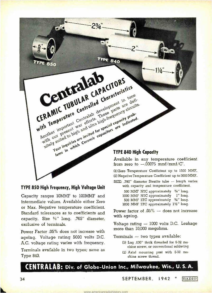
TYPE 850 High Frequency, High Voltage Unit
Capacity ranges 10MMF to 100MMF and intermediate values. Available either Zero or Max. Negative temperature coefficient. Standard tolerances as to coefficients and capacity. Size 5 /a" long. .765" diameter, exclusive of terminals.
Power Factor .05% does not increase with ageing. Voltage rating 5000 volts D.C.
A.C. voltage rating varies with frequency.
Terminals available in two types; same as Type 840.
TYPE 840 High Capacity
Available in any temperature coefficient from zero to -.00075 mmf /mmf /C °.
(1) Zero Temperature Coefficient up to 1500 MME'.
(2) Negative Temperature Coefficient up to 3000 MMF.
SIZE: .780" diameter Steatite tube - length varies with capacity and temperature coefficient.
500 MMF NTC approximately 3/4" long. 1000 MMF NTC approximately 1" long. 500 MMF ZTC approximately 3/4" long.
1000 MMF ZTC approximately 11/2" long.
Power factor of .05% - does not increase with ageing.
Voltage rating - 1000 volts D.C. Leakage more than 10,000 megohms.
Terminals - two types available: (1) Lug .030" thick threaded for 6 -32 ma-
chine screw, or conventional soldering
(2) Axial mounting post with 6 -32 ma- chine screw thread.
CENTRALAB: Div. of Globe -Union Inc., Milwaukee, Wis., U. S. A.
34 SEPTEMBER, 1942 * [RADIO
www.americanradiohistory.com
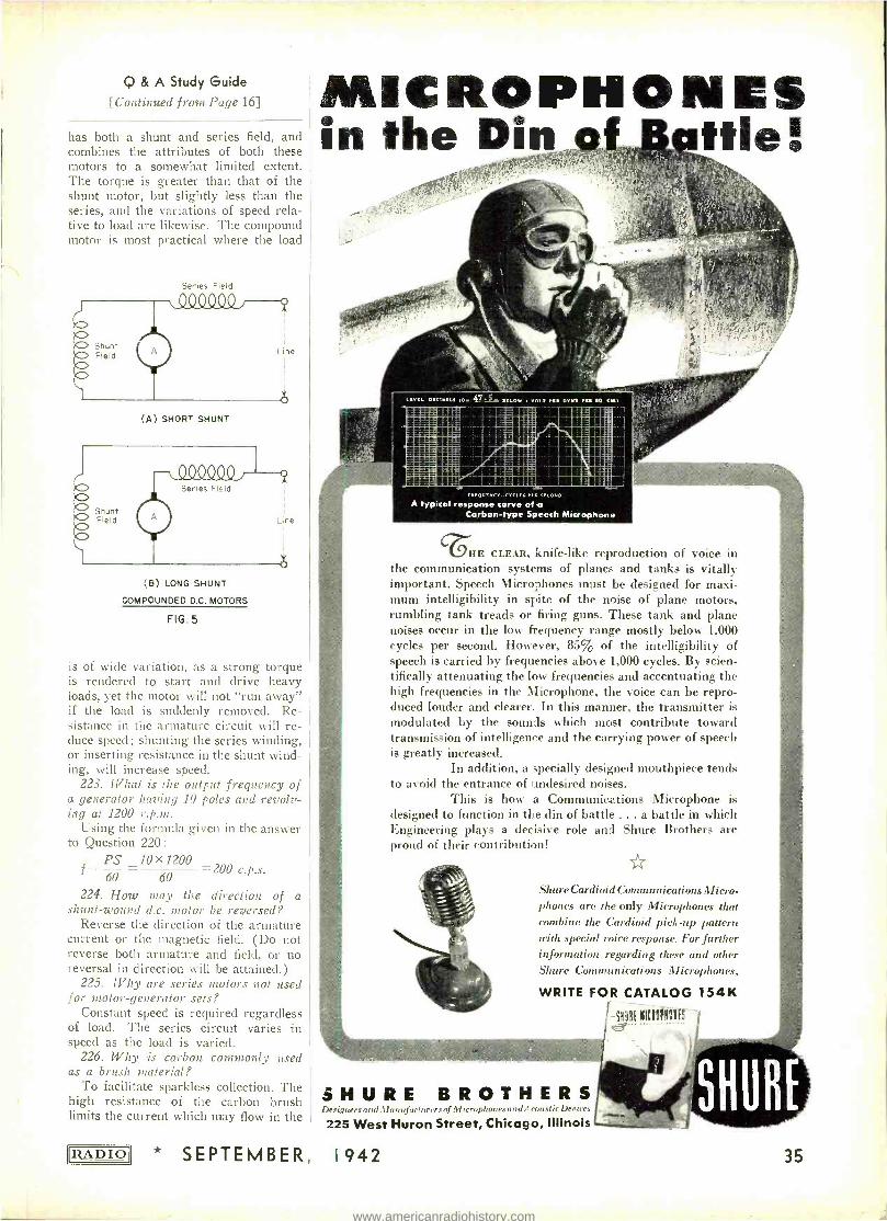
Q & A Study Guide [Continued from Page 16]
has both a shunt and series field, and combines the attributes of both these motors to a somewhat limited extent. The torque is greater than that of the shunt motor, but slightly less than the series, and the variations of speed rela- tive to load are likewise. The compound motor is most practical where the load
Series Field
MICROPHONES in the Din gf ? file!
LWtL D[CprLf 60-. i1G0 KLOw
(A SHORT SHUNT
Series Field
Line
(B) LONG SHUNT
COMPOUNDED D.C. MOTORS
FIG.5
is of wide variation, as a strong torque is rendered to start and drive heavy loads, yet the motor will not "run away" if the load is suddenly removed. Re- sistance in the armature circuit will re- duce speed; shunting the series winding, or inserting resistance in the shunt wind- ing, will increase speed.
223. What is the output frequency of a generator having 10 poles and revolv- ing at 1200 r.p.m.
Using the formula given in the answer to Question 220:
PS _10X1200 f 60 60 = 200 c.p.s.
224. How ma_v the direction of a shunt -wound d.c. motor be reversed?
Reverse the direction of the armature current or the magnetic field. (Do not reverse both armature and field, or no reversal in direction will be attained.)
225. Why are series motors not used for motor -generator sets?
Constant speed is required regardless of load. The series circuit varies in speed as the load is varied.
226. Why is carbon commonly used as a brush material?
To facilitate sparkless collection. The high resistance of the carbon brush limits the current which may flow in the
IRADIO1
.EOOIvC.-<.as FE.f. SECOND
A typical response curve of a Carbon -type Speech Microphone
VHE CLEAR, knife -like reproduction of voice in the communication systems of planes and tanks is vitally important. Speech Microphones must be designed for maxi- mum intelligibility in spite of the noise of plane motors, rumbling tank treads or firing guns. These tank and plane noises occur in the low frequency range mostly below 1,000 cycles per second. However, 85% of the intelligibility of speech is carried by frequencies above 1,000 cycles. By scien- tifically attenuating the low frequencies and accentuating the high frequencies in the Microphone, the voice can be repro- duced louder and clearer. In this manner, the transmitter is modulated by the sounds which most contribute toward transmission of intelligence and the carrying power of speech is greatly increased.
In addition, a specially designed mouthpiece tends to avoid the entrance of undesired noises.
This is how a Communications Microphone is designed to function in the din of battle ... a battle in Is hick Engineering plays a decisive role and Shure Brothers are proud of their contribution!
Shure Cardioid Communications Micro- phones are the only Microphones that combine the Cardioid pick -up pattern with special toice response. For further information regarding these and other Shure Communications Microphones,
WRITE FOR CATALOG 154K
SaOiE IiltIOPIONES
SHURE BROTHERS Designers and II n afacIurers of Microphones and Acoustic Devices
225 West Huron Street, Chicago, Illinois
* SEPTEMBER, 1 942 35
www.americanradiohistory.com
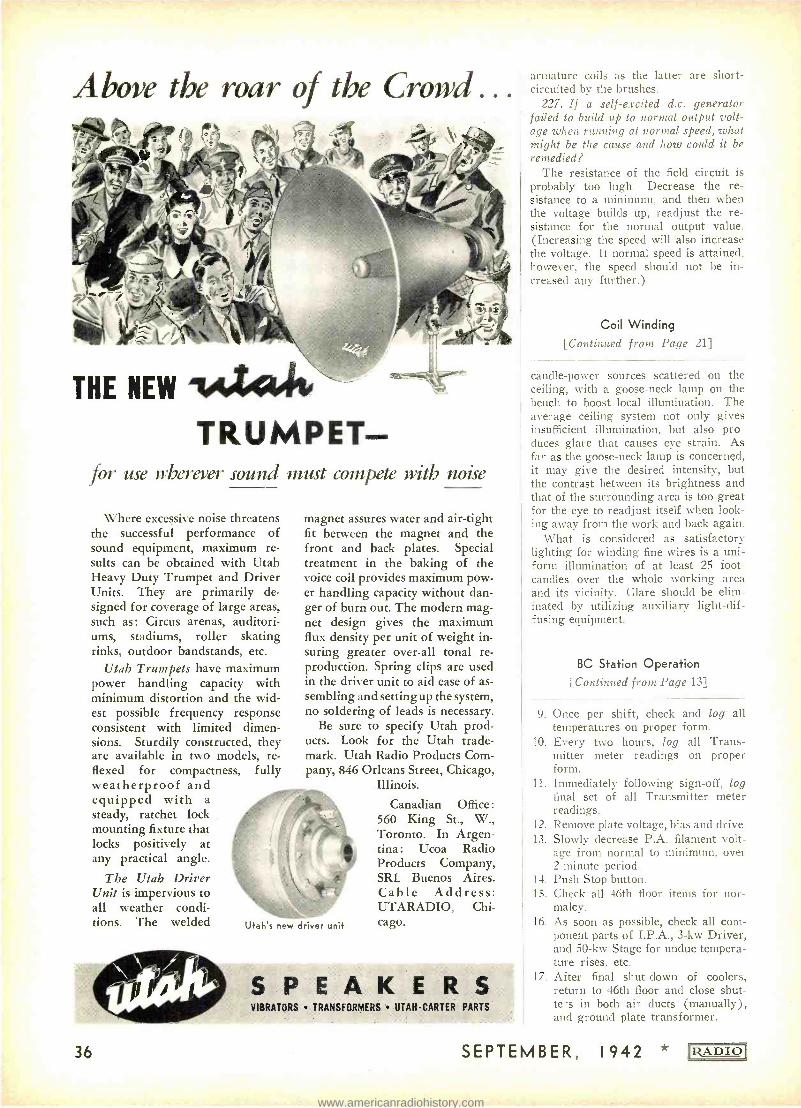
Above the roar of the Crowd...
THE NEW 1#44440
TRUMPET for use wherever sound must compete with noise
Where excessive noise threatens the successful performance of sound equipment, maximum re- sults can be obtained with Utah Heavy Duty Trumpet and Driver Units. They are primarily de- signed for coverage of large areas, such as: Circus arenas, auditori- ums, stadiums, roller skating rinks, outdoor bandstands, etc.
Utah Trumpets have maximum power handling capacity with minimum distortion and the wid- est possible frequency response consistent with limited dimen- sions. Sturdily constructed, they are available in two models, re- flexed for compactness, fully weatherproof and equipped with a steady, ratchet lock mounting fixture that locks positively at any practical angle.
The Utah Driver Unit is impervious to all weather condi- tions. The welded
magnet assures water and air -tight fit between the magnet and the front and back plates. Special treatment in the baking of the voice coil provides maximum pow- er handling capacity without dan- ger of burn out. The modern mag- net design gives the maximum flux density per unit of weight in- suring greater over -all tonal re- production. Spring clips are used in the driver unit to aid ease of as- sembling and setting up the system, no soldering of leads is necessary.
Be sure to specify Utah prod- ucts. Look for the Utah trade- mark. Utah Radio Products Com- pany, 846 Orleans Street, Chicago,
Illinois.
Canadian Office: 560 King St., W., Toronto. In Argen- tina : Ucoa Radio Products Company, SRL Buenos Aires. Cable Address: UTARADIO, Chi- cago. U +ah's new driver unit
36
VIBRATORS TRANSFORMERS UTAH -CARTER PARTS
armature coils as the latter are short - circuited by the brushes.
227. If a self -excited d.c. generator failed to build up to normal output volt- age when running at normal speed, what might be the cause and how could it be remedied?
The resistance of the field circuit is probably too high. Decrease the re- sistance to a minimum, and then when the voltage builds up, readjust the re- sistance for the normal output value. (Increasing the speed will also increase the voltage. If normal speed is attained. however, the speed should not he in- creased any further.)
Coil Winding
[Continued from Page 21]
candle -power sources scattered on the ceiling, with a goose -neck lamp on the bench to boost local illumination. The average ceiling system not only gives insufficient illumination, but also pro- duces glare that causes eye strain. As far as the goose -neck lamp is concerned. it may give the desired intensity, but the contrast between its brightness and that of the surrounding area is too great for the eye to readjust itself when look- ing away from the work and back again.
What is considered as satisfactory lighting for winding fine wires is a uni- form illumination of at least 25 foot - candles over the whole working area and its vicinity. Glare should be elim- inated by utilizing auxiliary light -dif- fusing equipment.
BC Station Operation [Continued from Page 13]
9. Once per shift, check and log all temperatures on proper form.
10. Every two hours, log all Trans- mitter meter readings on proper form.
11. Immediately following sign -off, log final set of all Transmitter meter readings.
12. Remove plate voltage, bias and drive. 13. Slowly decrease P.A. filament volt-
age from normal to minimum. over 2- minute period.
14. Push Stop button. 15. Check all 46th floor items for nor-
malcy. 16. As soon as possible, check all com-
ponent parts of I.P.A., 3 -kw Driver, and 50 -kw Stage for undue tempera- ture rises, etc.
17. After final shut -down of coolers, return to 46th floor and close shut- ters in both air ducts (manually), and ground plate transformer.
SEPTEMBER, 1942 !RADIO
www.americanradiohistory.com
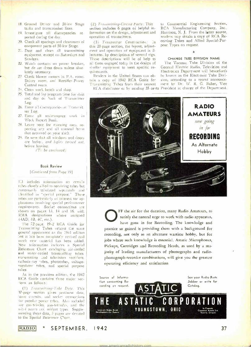
18. Ground Driver and 50 -kw Stage tanks and transmission lines.
19. Investigate all discrepancies re- ported during the day.
20. Check all spacings and clearances of component parts of 50 -kw Stage.
21. Dust and clean all transmitting equipment, except on Saturdays and Sundays.
22. Watch contacts on power breaker, but do not dress down unless abso- lutely necessary.
23. Check blower motors in P.A. room, Driver room, and Rectifier -Power Control room.
24. Clean work bench and shop. 25. Total Ímcl :og program time for shift
and day on back of Transmitter Log.
26. Enter all Ciscrepancies on Transmit- ter Log.
27. Enter all maintenance work in Work Report Book.
28. Leave note for morning men, re- porting ary and all unusual items that occurred on your shift. Be sure that all windows and doors are locket, and lights turned ont, before leaving.
(To be continued)
29.
Book Review
[Continued from Page 19]
III includes information on certain tubes closely allied to receiving tubes but customarily tabulated separately and identified as "special purpose." These tubes are particularly of interest for ap- plications involving special performance requirements. Socket connections are shown on pages 13, 14 and 16, with RMA designations where assigned (4AD, 4B, 4C, etc.).
The 72 -page, 1942 RCA Guide for Transmitting Tubes retains the same general appearance as the 1941 edition but it has begin completely revised and much new material has been added. New information includes a Special Reference Chart cataloging air -cooled and water -cooled transmitting tubes, transmitting and television rectifiers, cathode -ray tubes, phototubes, voltage - regulator tubes, and special purpose tubes.
As in the previous edition, the 1942 RCA Guide contains three major sec - :ions, as follows :
(1) Transmitting -Tube Data: This 37 -page section gives pertinent data, basic circuits, and socket connections for popular power tubes. Also included are gas -triodes, gas- tetrodes, and the u -li -f acorn and midget types. Supple- menting these data, 5 pages are devoted to the Special Reference Chart.
RADIO
(2) Transmitting- Circuit Facts: This section includes 6 pages of helpful in- formation on the design, adjustment and operation of transmitters.
(3) Transmitter Construction : :n this 20 -page section, the layout, adjust- ment and operation of equipment is il- lustrated by descriptions of several rigs. These descriptions will be of help to all those engaged today in the design of similar equipment to meet specific re- quirements.
Readers in the United States can ob- tain a copy of 1942 RCA Guide for Transmitting Tubes from their nearest
RCA distributor or by sending 35 cents
tu Commercial Engineering Section, RCA Manufacturing Company, Inc., Harrison, N. J. From the latter source, readers may obtain a copy of RCA Re- ceiving Tubes and Allied Special -Pur- pose Types on request.
CHANGE TUBE DIVISION NAME The Vacuum Tube Division of the
General Electric Radio, Television and Electronics Department will henceforth be known as the Electronic Tube Divi- sion, according to a recent announce- ment by Dr. W. R. G. Baker, Vice President in charge of the Department.
RADIO AMATEURS
now going
in for
RECORDING As Alternate
Hobby
OFF the air for the duration, many Radio Amateurs, to
satisfy the natural urge to work with radio apparatus,
have gone in for Recording. The knowledge and
practice so gained is providing them with a background for recording, not only as an alternate wartime hobby, but for
jobs where such knowledge is essential. Astatic Microphones,
Pickups, Cartridges and Recording Heads, as used by a ma-
jority of leading manufacturers of phonographs and radio -
phonograph- recorder combinations, will give you the greatest
operating efficiency and satisfaction.
Source of Informa- tion concerning Re-
cording on request. AST TIC See your Radio Parts
Jobber or write for Catalog.
THE ASTATICCORPORATION Li<o.ed Under. finish
Development Co Potent. YOUNGSTOWN, OHIO
In Conoda Conodlan A.toik Lid
7otonio Oniai;c
* SEPTEMBER, 1942 37
www.americanradiohistory.com
New Products
[Continued from Page 24]
The maximum horsepower motor this size Motron is capable of directing is in general directly proportional to the supply frequency, if the effects of wind- age, hysteresis and eddy current losses are neglected. This is because the torque of an induction motor is propor- tional to load current and speed is pro- portional to frequency. Therefore to a first approximation, on 400 -cycle cur- rent, 6 to 7 times the horsepower of 60
cycles supply should be obtained, if suit- able design constants are used. The 2g lb. Control should direct a 1/6 maxi- mum h.p. motor on 400 cycles.
For further details, address W. C. Robinette, 804 No. Chester, Pasadena, Calif.
* JENSEN ANTI -CORROSION HYPEX
PROJECTORS
Series 201 Hypex Projectors are for the reinforcement of speech or other audio sound at relatively high levels and over wide areas. Compared with con-
Y
IA Designed to Army Air Force Specifications . .
4 GUARDIAN * Is your problem the transmission of power for control of aircraft armaments? Aircraft navi- gation? Aircraft accessory circuits?
If so, Guardian has the answer. Units range from a midget relay weighing less than one ounce and capable of controlling 150 watts ... up to a
Solenoid Contactor weighing less than two pounds and handling 200 amperes continuously (at 32 V., D.C.) and 1000 amperes on surges. 84 Solenoid Contactor
We've built single switches. We've built complex electrical assemblies that control machine gun turrets. And the aircraft industry and associate parts
manufacturers know from these and hundreds of other units that they can
count on Guardian for approved controls -that Guardian has the equipment and the "know how" to do their job right. And, above all . . . they know Guardian's reputation for quality delivery.
New circular on B -4 Solenoid Contactor available now. Write today.
GUARDIAN ELECTRIC 1 6 0 5 W E S T W A L N U T S T R E E T
38
C H I C A G O , I L L I N O I S
LARGEST LINE OF RELAYS SERVING AMERICAN WAR INDUSTRY
ventional or standard commercial prod- ucts of this kind, these designs are distinguished by strong mechanical con- struction and ability to withstand the corrosive and other deteriorating effects of continued exposure to salt -laden at- mosphere, highly humid climates and other severe weather conditions.
Voice -coil impedance is 16 ohms nom- inal value. Nominal low- frequency cut- off is 160 cycles, high -frequency cutoff approximately 5000 cycles, with a maxi- mum of ±5 db variation in range from 200 to 5500 cycles.
Measured pressure output is 32.7 bars (104 db) at distance of ten feet from mouth of horn when measured in free space with one watt input, 700 -1300 cycle warble frequency. Total radiation angle is 54° (700 -1300 warble), with maximum loss of 3 db throughout total angle.
Power handling capacity is 20 watts minimum when 700 -1300 warble is con- tinuously applied for 100 hours. This accelerated life test insures 25 -watt peak power -handling capacity in conventional use.
For further details, address Jensen Radio Mfg. Co., 6601 So. Laramie Ave., Chicago.
* LOW- RADIATION RECEIVER
The elimination of one direct cause of American ship losses was made pos- sible recently by the introduction of a new low- radiation radio receiver by the E. H. Scott Radio Laboratories, Inc., Chicago, Illinois. Unlike ordinary ra- dios (large or small) this specially de- signed set gives off no signal detectable by enemy direction finders, and it thus foils subs and ships which have hereto- fore been able to track down our boats from distances of 100 miles or more away simply by listening to the constant oscillator radiations sent out by the en --
tertainment radios aboard them. The new Scott Marine Model SLR -
12-A eliminates this danger to ship- ping by cutting oscillator radiation to
SEPTEMBER, 1942 RADIO
www.americanradiohistory.com
the point of absolute safety. It has full approval from the F.C.C. for use at sea on both broadcast and shortwave bands, assuring for the first time excellent per- formance at greatest distances from land under difficult shipboard conditions.
Many shippirg authorities are con- vinced that this low- radiation receiver offers the solution to a number of to- day's tough shipping problems, not only because it is sale and protects men, ships and materials, but because it lessens hiring difficulties and greatly boosts shipboard morale. For full details about tins marine receiver, write to E. H. Scott Radio Laboratories, Inc., 4450 Ravenswood Avenue, Chicago, Illinois.
NEW CLAROSTAT STABILIZED ELEMENT CONTROLS
Important developments in the proc- essing of resistive coatings have re- sulted in potentiometers and rheostats claimed to be virtually on a par with ware -wound units in matters of resist- ance permanence, immunity to climatic ccnclitions and wearing qualities.
Clarostat Series 37 controls employ the new stabilized element that takes the form of resistive coating on a bakelite base, being practically as smooth and hard as glass. The element is chemically treated during processing to eliminate all further changes in its composition. It is likewise heat treated tc stabilize its temperature and humid- ity characteristics.
Controls incorporating the new stabi- lized element were quietly introduced to
LIZA D I O
the trade many months ago, so as to get the reaction of users out in the field. Users have been prompt to spot the new element. Accurate resistance values first and last, even after months of continu- ous usage under adverse conditions, have been noted. Likewise noted were the accuracy of tapers, taps, and hop - offs. So much so that leading instru- ment makers are now using these con- trols in place of former wire -wound units even for relatively low resist- ance values. Series 37 controls with the new stabilized elements are made by Clarostat Mfg. Co., Inc., 285 -7 N. 6th St., Brooklyn, N.Y.
UNIVERSAL MIKE SWITCH
Universal Microphone Co., Ingle- wood, Cal., has announced the distribu- tion of standard microphone switch SW -141, available in quantity orders to government contractors and sub-con- tractors. The assembly is housed in plain plastic case with hanging eye at the top.
SW -141 switch is complete with cable strain relief construction. The switch may be used as a press -to -talk type, or the locking button may be used on the "on" position.
Lightweight, compact, durable, SW- 141 switch can be adapted for various
COMPLETE STOCKS
* We still have large stocks of receivers, 21/2
meter equipment, me-
ters, tubes, transform- ers, resistors, condensers,
panels, chassis, and radio parts of all sorts. We sell and rent code teach- ing equipment. Your orders and inquiries in- vited.
LET'S ALL
PITCH IN!
WE CAN all help win this war by selling our government the communication receivers and transmitters they need quickly and in sufficient quanti- ties.
That is the reason we are paying highest cash prices for used communications equip- ment.
When this war for the "four freedoms" is over you will un- doubtedly be in the market for new equipment and by taking advantage of our offer to pur- chase your present equipment at highest cash prices you will be in a position to buy a new and better receiver than you now own.
Write, telephone or telegraph us description of your used communications receivers and transmitters of standard make; you will be paid cash immedi- ately without bother or red tape.
We also have a store at 2335 Westwood Blvd., West Los An- geles, Calif.
"WORLD'S LARGEST DISTRIBUTOR OF COMMUNICATIONS RECEIVERS"
* * * * * * * * * * * * * *
* SEPTEMBER, 1942 39
www.americanradiohistory.com
communications devices for mobile
units. It was specifically designed and engineered for use on cord assembly CD 318, as well as cord CD 508, but also has other applications. It has been built to
specifications of the Army Signal Corps
and approved by that office.
COMPENSATION AND EMPLOYMENT IN BROADCASTING SHOWS 1941 INCREASE
Personnel increases and advances in average salaries in the radio broadcast- ing industry again were reflected in an- nual financial reports of stations and networks which are filed with the Fed- eral Communications Commission. Us- ing the week beginning October 12,
1941, as a base period, three na- tional networks, five regional chains and 817 standard broad- cast stations reported that 23,666 persons were employed on a full time basis having a weekly pay- roll of $1,138,249. This showed a personnel increase of 2,020 peo- ple for the industry, and a growth of the weekly salary total by $121,883 over a similar period in 1940.
Exclusive of executive person- nel the average weekly wage at the national radio chains was $57.41, representing a dip of fourteen cents from the year be- fore, while the $48.39 average at regional networks represented a $6.81 climb, and individual sta- tion increases of $1.13 brought average pay envelopes to $38.88. Staff musicians and artists em- ployed full time are included in the totals but those persons hired by radio departments of advertis- ing agencies or program spon- sors are not. The eight broad- casting systems had 4,009 full - time workers and the remaining employees were on the rolls of individual stations. FCC ac- countants after studying earlier reports stated that 1941 returns show the consistent growth of employment and average compen- sation within the broadcasting business.
The average weekly compensa- tion for the 19,567 full -time em- ployees of the 817 stations was $45.15, an increase of $1.64 over 1940. Of these full -time em- ployees 2,426 were in the execu- tive class with an average weekly pay of $89.46, an increase of $5.04 over 1940, while the re- maining 17,141 below the grade of executive had an average weekly income of $38.88, an in- crease of $1.13 over 1940. For the major network executives the average was $258.83 as compared with $251.68 for 1940, while the major network employees below the grade of executive was $57.41, a decrease of 14 cents from 1940. It is noted that the employees of the regional net- works had a more encouraging experience with the executive class, advancing from an average
A Bull's -Eve for (Addy
Mallory Approved Precision Products are right because they are built up to a standard of quality and not down to a standard of price.
There is no need, therefore, to use parts that are "almost" as good as Mallory ... parts that are "fairly satis- factory" ... or parts that are "just about the same ".
Remember, too, that Mallory offers you technical assistance promptly and without charge. Mallory's "How -To- Do-It Dept." is always at the service of engineers, amateurs, and service- men. Do you have a copy of the Mallory catalog? If not, write for one now.
P. R. MALLORY & CO., Inc. INDIANAPOLIS INDIANA
Cable Address - PELMALLO
Use
ALLOR APPROVED
PRECISION PRODUCTS
40
weekly pay of $91.50 in 1946 to $137.57 in 1941 while those below the grade of executive were having an increase in pay from $41.58 in 1940 to $48.39 in 1941.
NEW 100- KILOWATT TRANSMITTER FOR WGEO
A new 100 -kilowatt radio transmit- ter has completed extensive tests and is now operating full power for WGEO, one of the two General Electric inter- national broadcasting stations in Sche- nectady, it was announced Aug. 13 by Robert S. Peare, G -E broadcasting manager.
The transmitter replaces one of equal power released at government request last December to K.WID, San Fran- cisco, to augment the programs of KGEI, General Electric station there, and to increase California short -wave facilities to combat Japanese propa- ganda in the Pacific.
During construction of the new trans- mitter, WGEO continued on the air without loss of time by the use of a previously licensed 25- kilowatt trans- mitter.
* HALLICRAFTERS AWARDED ARMY AND
NAVY "E" CITATION The Hallicrafters Company have been
notified by Under Secretary of War Robert P. Patterson that they have been awarded the Arne* and Navy "E" Ban- ner, according to an announcement by W. J. Halligan, President of Hallicraft- ers.
The Company was complimented in Mr. Patterson's notification letter for the "high achievement attained in the production of war equipment.
"The high and practical patriotism of the men and women of The Hallicraft- ers Company is inspiring. Their record will be difficult to surpass, yet the Army and Navy have confidence that it was made only to be broken."
Formal presentation of the "E" Ban- ner was made Wednesday, September 9th, at the Hallicrafters Main plant where Army and Navy officers made the award. Chicago civic leaders and State officials were present.
* F. R. TUERK NEW UTAH PRESIDENT
Effective September 1, 1942, Mr. Fred R. Tuerk becomes President of Utah Radio Products Company. Mr. G. Hamilton Beasley, President for the last five years, has been elected Chairman of the Board.
Mr. Beasley is also President of The Caswell- Runyan Company of Hunting- ton, Indiana (wholly owned subsidiary of Utah Radio Products Company). Due to the serious illness of Mr. J. W. Caswell, Mr. Beasley will devote a greater portion of his time to the Cas- well- Runyan Company.
He will continue to take an active
SEPTEMBER, 1942 IRADIOI
www.americanradiohistory.com
part in the management of Utah, whose entire production facilities are and have been for some time past concentrated on war products.
Outside of the above change, the Utah executive roster remains as it has been for many years : Henry S. Neyman, Vice President and Treasurer ; W. Dumke, Vice P:esident and Secretary ;
W. A. Elmore, Chief Engineer, and O. F. Jester, General Sales Manager.
WALL CHART OFFERED BY ELASTIC STOP NUT
A wall chart, explaining the uses of its various types of self -locking nuts, is being distributed by Elastic Stop Nut Cot poration, Union, New Jersey, to en- gineering departments, drafting rooms, maintenance shops and schools.
The center of the chart is devoted to ar_ illustrated description of the basic principle by which a self -locking action is obtained in all Elastic Stop Nuts. This is followed by illustrations of some of the advantages to be obtained by the use of the nuts and, completing the presentation, there are cross -section drawings showing the method of appli- cation of the nine types most generally used, with corresponding photographs of these types.
The chart measures 21 by 27 inches and is reinforced at top and bottom by metal strips, with an eyelet for hang- ing. Copies can be obtained by writing to the manufacturer.
* CORRECTION
In the schematic diagram of "The Transitron Audio Oscillator," shown on page 19 of the August 1942 issue, the connections of the control grid and the suppressor gr.1 of the 6J7 should be re- versed, with the suppressor connecting to the arm of potentiometer R2 and the control grid connected to the cathode.
* FARNSWO2TH PROMOTES KELSO
Mr. Glen E. Kelso has been appointed superintendent of manufacturing for the Fort Wayne plant of the Farnsworth Television & Radio Corporation accord- ing to an announcement by Mr. R. C. Jenkins, general superintendent of Farnsworth plants.
Mr. Kelso :s well qualified by experi- ence to fill his new position inasmuch as he has been acting in an executive capacity in the manufacturing division of the company since its inception and had served with the predecessor organi- zation in varntis supervisory capacities since 1929.
* ISSUANCE OF AMATEUR STATION
LICENSES DISCONTINUED The Commission by its Order No.
7 -B adopted September 15th, has dis-
RADIO * SEPTEMBER,
continued the issuance of new, renewal, or modified amateur station licenses until further order of the Commission. Th.s action has been taken in view of the many difficult administrative problems which have arisen in connection with the issuance of amateur station licenses as a result of the war. Inasmuch as many licensees are in the military seri- ices or engaged in war industries in various parts of the country, it is impossible for such station licensees to exercise proper con- trol of transmitting apparatus and the control of the premises upon which such apparatus is located as required by the Rules and Regulations Governing Amateur Radio Stations and Op- erators.
Commission Orders No. 87 and 87 -A adopted December 8, 1941 and January 8, 1942, re spectively, require complete ces- sation of all amateur radio oper- ation in the interest of national security. The Commission, how- ever, continued to renew and modify existing amateur station licenses in view of possible util- ization of such stations in con- nection with Civilian Defense ac- tivities. The establishment of the \Var Emergency Radio Service, however, will provide Civilian Defense and State Guard organ- izations with the desired emer- gency communication in connec- tion with the national defense and security. The Commission will continue its policy in regard to the issuance of new or renewed amateur operator licenses or modification of such licenses for change in operator privileges. The holder of an amateur oper- ator license desiring to maintain his amateur status should submit application for amateur operator and amateur station license re- newal in accordance with the Rules.
With respect to amateur sta- tion licenses which are valid as of the date of adoption of Order No. 87 -B and are not revoked prior to their expiration, it is contemplated that the licensees thereof, who maintain valid ama- teur operator licenses, will be granted appropriate amateur sta- tion authorization when amateur stations are again allowed to be operated, subject to the filing of such additional application (s) as may be required. It is further contemplated that the future op- eration of amateur stations will be authorized upon such bands of frequencies as may then be allocated to the amateur service.
1942
Insofar as it is possible and practicable to do so, the call letters of outstanding amateur station licenses will be re- served for assignment to the presen- station licensee upon proper application when licensing of amateur stations is resumed.
Quartz received its first mention in the history of fie ancient Greeks. They be- lieved that :his crystal clear mineral was water frozen under intense cold. Accord - ingly,it was ;ailed Kpúaradaos - Clear Ice. Quartz is not frozen water, of .course, but ,Silicon Dio_ide (SiO7) and is a common mineral sulstance. Common, yes, hut to date only quartz from Brazil suits the re- quirements for quartz oscillating crystals.
Today, ti-a substance which was a curi- osity to the Greeks, is a vital material to our war effort. Innumerable crystal units are needed for radio communications equip-
. ment so that our men can be in constant touch with each other. Bliley's jcb is to supply its share (and more if possible)- that's what is being done.
BLILEY F1 EOtÇENCY CONTROL
BLILEY ELECTRIC CO., ERIE, PA.
41
www.americanradiohistory.com
okes - la# SWItche$
Iß YOUR:
ON THE WAR FRONT -Many of you now in active service have long been familiar with the dependability of Ohmite Products. When you notice so many of these same units in vital war equipment on land, at sea and in the air, it gives you added assur- ance and helps you fight a better fight.
ON THE HOME FRONT -Here, too, you find innumerable Ohmite Re- sistance Units in radio, communica- tions and electronic devices, in test apparatus and electrical control equipment. This knowledge helps you do a better job in dealing with today's resistance- control problems or in maintaining the service of ex- isting equipment.
Send for These Handy Aids Ohmite Ohm's Law Calculator Helps you figure ohms- watts, volts, amperes -quickly, eas- ily. All values are direct read- ing. No slide rule knowledge necessary 41/2 x 9" Send only 10c in coin to cover handling cost
Quick -Reference Catalog 18 Gives up -to -date information
on the wide range of Ohmite Stock resistors, rheostats, chokes
and switches used in all types of applications. Write for it now-
it's Free! Ohmite Jobbers Everywhere
OHMITE MANUFACTURING COMPANY 4868 Flournoy St., Chicago, U.S.A.
Altevia Alti OHMOTG tisi TP swl
42
RAULAND ACQUIRES AMERICAN RIGHTS TO BRITISH TELEVISION PATENTS
Mr. E. N. Rauland, president of the Rauland Corporation of Chicago, an- nounces a significant expansion of the activities of that company, through the acquisition of title to the American patents of the Gaumont -British Picture Company of America, Cinema- Televi- sion, Ltd., and Baird Television.
An interview with Mr. C. P. Cush - way, vice -president of the Rauland Corporation, reveals that Rauland has acquired all of the American interests and the exclusive rights not only to all existing patents of these companies for the Western Hemisphere, but the rights to patents on all future developments of the Gaumont -British Picture Corp., Ltd., of London, England, in the fields of Television, Electronic tube develop- ments, and other light- sensitive devices.
The acquisition of these patents and interests will result largely in activities in the design and manufacture of equip- ment for Television transmission and re- ception, with emphasis on theatre in- stallations (in which there has been con- siderable progress in Great Britain). Further, the patents are concerned also with sound transmission and reception for use with radio and television. Fac- simile and photo -telegraphy transmission and reception are additional fields in which activities are planned. Military
and industrial application of light- sensi- tive devices are an important aspect of the patent acquisition, particularly as the Rauland Corporation is engaged al- most exclusively in war production.
The Rauland Corporation has also taken over in its entirety the laboratory and engineering staff as well as the equipment of Cinema -Television, Baird Television and the Gaumont- British Corporation of America. This covers all of the United States interests of the par- ent Gaumont -British Company, Ltd., of London, England.
Headed by Dr. C. S. Szegho, Chief Research Physicist, a leading European figure in electronic research, the new personnel has been added to the present laboratory and engineering staff of the Rauland Corporation, and plans for the expansion of electronic engineering ac- tivities are already under way.
* JOLLIFFE APPOINTED VICE PRESIDENT
AND CHIEF ENGINEER OF RCA
Dr. Charles Byron Jolliffe, Assist- ant to the President of the Radio Cor- poration of America, and Chief Engi- neer of RCA Laboratories, has been appointed Vice President and Chief Engineer of RCA Manufacturing Com- pany, Camden, N.J., according to a joint announcement made today by G. K. Throckmorton, Chairman of the Execu-
[Continued on page 45]
COR P
DYNAMOTORS
. ..
CONVERTERS
R A;. TORS
..
D' r, MOTORS R PLANTS cE
ERROR DDRESS ER GEV.g.MOTÖ
R WARREN STREET. NCY'ONGOL
RIE SIMON/RICE, NEW VORk
SEPTEMBER, 1942 'IZADIO'
www.americanradiohistory.com
4#uwwice#ne4
This is the last issue of "RADIO" to be sold on a newsstand
"RADIO " -The o nly magazine devoted exclu- sively to radio research, design, production and o peration.
"RADIO" is edit- ed for engineers, designers, tech- n icians, produc- tion men, and o perations per- sonnel.
Effective with the October, 1942, issue "RADIO" will be available only on an annual subscription
basis -$3.00 for 1 year, $5.00 for 2 years.
SPECIAL SUBSCRIPTION OFFER FOR A LIMITED TIME
TEAR OUT AND MAIL
15 Big Issues - $3.00
21 Big Issues - $5.00
regular price is
$3.00 for 12 issues
regular price is
$5.00 for 24 issues
Special: Subscription price to men in the armed service $1.50 per year
Use the Coupon Below
"RADIO" Radio Magazines, Inc., 132 W. 43rd St., New York City
SIRS: Please send me the next
TEAR OUT AND MAIL
SPECIAL MONEY- SAVING OFFER
15 issues $3.00 -27 issues $5.00
issues of RADIO. Here is my check (or money order) for $
(Remit by Check or Money Order. We cannot assume responsibility for cash sent thru mails)
Name (print carefully)
Address _ City S t a t e _- _ _-
Name of Firm You Work For
Title or Position You Hold (please be explicit)
RADIO * SEPTEMBER, 1942 43
www.americanradiohistory.com
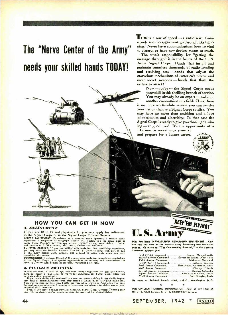
The "Nerve Center of the Army"
needs your skilled hands TODAY!
THIS is a war of speed -a radio war. Com- mands and messages must go through like light- ning. Never have communications been so vital to victory, or have new devices meant so much.
The whole responsibility for "getting the message through" is in the hands of the U. S. Army Signal Corps. Hands that install and maintain countless thousands of radio sending and receiving sets - hands that adjust the marvelous mechanisms of America's newest and most secret weapons - hands that flash the orders to attack!
Now - today - the Signal Corps needs your skill in this thrilling branch of service. You may already be an expert in radio or another communications field. If so, there
is no more worth -while service you can render your nation than as a Signal Corps soldier. You may have no more than ambition and a love of mechanics and electricity. In that case the Signal Corps is ready to give you thorough train- ing - at good pay! It's the opportunity of a lifetime to serve your country and prepare for a future career. ,.
U.S.ARMY i stwt awn C
e
t
HOW YOU CAN GET IN NOW 1. ENLISTMENT If you are 18 to 45 and physically fit, you may apply for enlistment in the Signal Corps or in the Signal Corps Enlisted Reserve. DIRECT ENLISTMENT: Experience as a licensed radio operator, a trained radio repairman, a telephone or telegraph worker, will qualify you for active duty at once. From Private's pay you can advance rapidly as you earn higher technical ratings -up to $138 a month, with board, shelter and uniforms. ENLISTED RESERVE: If you are skilled with tools but lack qualifying experience, you may enter the Enlisted Reserve. You will be given training, with pay, in one of the many Signal Corps schools, and ordered to active duty when you have completed the course. COMMISSIONS: Graduate Electrical Engineers may apply for immediate commissions in the Signal Corps. And special opportunities for training and commissions are open to Juniors and Seniors in electrical engineering colleges.
2. CIVILIAN TILIIItiING If you are over 16 years of age, and even though registered for Selective Service, have not received your order to report for induction, the Signal Corps offers you an outstanding opportunity.
If you have ability with tools -if you want to secure training in the vitally impor- tant field of communications -you may attend a school in or near your home city. You will be paid not less than $1020 per year while learning. And when you have finished your training -in 9 months or less -you can advance to higher pay as your technical skill increases.
Even if you have a minor physical handicap, Signal Corps Civilian Training may Bice you the chance you've wanted to serve the Army of the United States.
44
" I(EEP'EM FL17NG r
r.
U. S. Armÿ FOR FURTHER INFORMATION REGARDING ENLISTMENT - Call and talk this over at the nearest Army Recruiting and Induction Station. Or write to: The Commanding General," of the Service Command nearest you:
First Service Command Boston, Massachusetts Second Service Command Governors Island, New York Third Service Command Baltimore, Maryland Fourth Service Command Atlanta, Georgia Fifth Service Command Fort Hayes, Columbus, Ohio Sixth Service Command Chicago, Illinois Seventh Service Command Omaha, Nebraska Eighth Service Command Fort Sam Houston, Texas Ninth Service Command Fort Douglas, Utah
Or write to: Enlisted Branch, AG -1, A.G.O., Washington, D. C.
FOR CIVILIAN TRAINING INFORMATION - Call at any office of the U. S. Civil Service or U. S. Employment Bureau.
SEPTEMBER, 1942 * IRADIO)
www.americanradiohistory.com
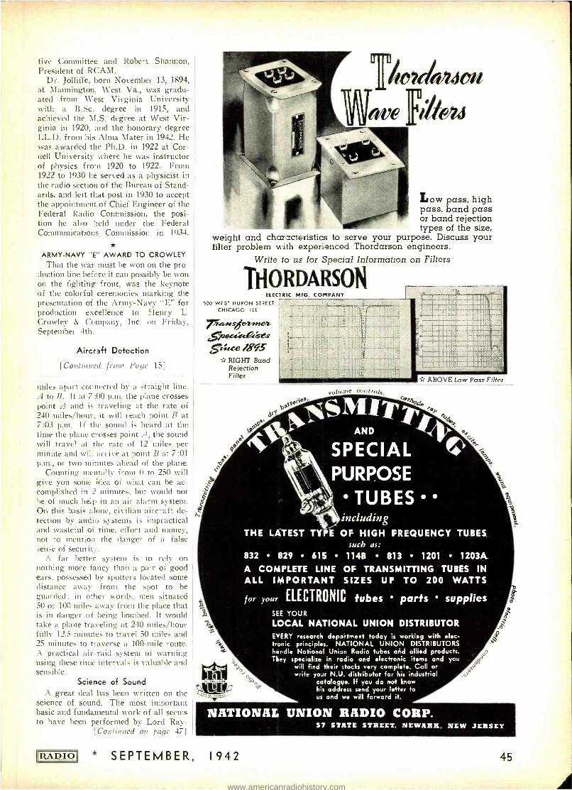
tive Committee and Robert Shannon, President of RCAM.
Dr. Jolliffe, born November 13, 1894, at Mannington, West Va., was gradu- ated from West Virginia University with a B.Sc. degree in 1915, and achieved the M.S. degree at West Vir- ginia in 1920, and the honorary degree LL.D. from his Alma Mater in 1942. He was awarded the Ph.D. in 1922 at Cor- nell University where he was instructor of physics from 1920 to 1922. From 1922 to 1930 he served as a physicist in the radio section of the Bureau of Stand- ards, and left that post in 1930 to accept the appointaient of Chief Engineer of the Federal Radio Commission, the posi- tion he also held under the Federal Communications Commission in 1934.
ARMY -NAVY "E" AWARD TO CROWLEY That the war must he won on the pro-
duction line before it can possibly be won on the fighting front, was the keynote of the colorful ceremonies marking the presentation of the Army -Navy "E" for production excellence to Henry L. Crowley & Company, Inc. on Friday. September 4th.
Aircraft Detection
[Continued froid Pays' 15]
miles apart connected by a straight line. A to B. If at 7 :00 p.m. the plane crosses point A and is traveling at the rate of 240 miles /hour, it will reach point B at 7 :03 p.m. I f the sound is heard at the time the plane crosses point A, the sound will travel at the rate of 12 miles per minute and will arrive at point B at 7:01 p.m., or two minutes ahead of the plane.
Counting mentally from 0 to 250 will give you some idea of what can be ac- complished in 2 minutes, but would not be of much help in an air alarm system. On this basis alone, civilian aircraft de- tection by audio systems is impractical and wasteful of time, effort and money, not to mention the danger of a false sense of security.
A far better system is to rely on nothing more fancy than a pair of good ears, possessed by spotters located some distance away from the spot to be guarded ; in other words, men situated 50 or 1011 miles away from the place that is in danger of being bombed. It would take a plane traveling at 240 miles /hour fully 12.5 minutes to travel 50 miles and 25 minutes to traverse a 100 -mile route. A practical air -raid system of warning fusing these time intervals is valuable and sensible.
Science of Sound A great deal has been written on the
science of sound. The most important basic and fundamental work of all seems to have been performed by Lord Ray -
[Continued on page 47]
RADIO)
u
r
Low pass, high pass, band pass or band rejection types of the size,
weight and characteristics to serve your purpose. Discuss your filter problem with experienced Thordarson engineers.
Write to us for Special Information
THORDARSON ELECTRIC MFG. COMPANY
500 WEST HURON STREET
CHICAGO I L L
Tira,Ars rnez
grace 1893 RIGHT Band Rejection Filter
c".
ay
on Filters
volu?ne cc
th tteo AND it
SPECIAL PURPOSE
TUBES
ABOVE Low Pass Filter
including THE LATEST TYPE OF HIGH FREQUENCY TUBES
such as: 832 829 615 114B 813 1201 1203A
A COMPLETE LINE OF TRANSMITTING TUBES IN ALL IMPORTANT SIZES UP TO 200 WATTS
for your ELECTRONIC tubes parts supplies SEE YOUR
LOCAL NATIONAL UNION DISTRIBUTOR EVERY -esearch department today is working with elec- tronic principles. NATIONAL UNION DISTRIBUTORS handle National Union Radio tubes aéd allied products. They specialize in radio and electronic items and you
will find their stocks very complete. Call or write yoJr N.U. distributor for his industrial
catalogue. If you do not know his address send your letter to us and we will forward it.
NATIONAL UNION RADIO CORP.
* SEPTEMBER, 1942
57 STATE STREET, NEWARK, NEW JERSEY
45
www.americanradiohistory.com
L MUHLEMAN
LEE ROBI NSON
S. R. CO WAN 1911
R
N AND OPERATION
ESTP8L,5"ED
DEVpTED 10 RADIO RESEARCH,
DESIGN, G N, PRODUCTION
RADIO MAGAZINES, INC.
EXCLUSIVELY
132 WEST 43rd STREET,
NEW YORK, N. Y.
CHickering 4--3278-4
$eptember 23, 1942
Industry' 1917)
To The Radio established
publication, try's oldest
P Inc es
Gentlemen: industry's Magazines, Inc., comprises
__the radio Radio ent &
"RADIO "--the and Published
by l of Radio
Magazines, dice- Presid sole
is now owned
publishing Person? (Bud)
Muhl ger, who arew th the
Corporate and P publisher;
M.
gusinescl Manager, Cooperation ley' as
The Core President & surer & e
Service-Dealer' Lee Robinson,
Pres Cowan, Treasurer work in "Radio k R (Sandy)
w Corporation will to Publish
S. R. continues Editor; which Inc.,
stockholders. Corp., Publishing ices of
Radio Magazines,
Cowan Pub offs to which address f.
heretofore. advertising City,
directed here
editorial and New York dire
edito Cuts should be
"vertical" EXecutiá'132 W. 43rd Street, as n, a
copy astern research,
design, located advertising its present resea rtica a-
ondence+ continue phases needed such correspondence, n will con vely all
P long eying develop-
ments
exclusively n engineering follow. Editorially covering ghe Radio
Industry progress
has an
ubI on cov r
present-day radio Perron
sure
copies will icati
monthly publication operation. p resen no production
and will cover
P important post-war
Henceforth P e try's 12,000
+RADIO vitally scope. oto the tion with an dens its
innus forces
"RADIO" now broadens month
the radio in the armed r copy
of
sold
nRAD every mon technicians receive thei
In circulation Instead,
nts, tecmen__will the a d
scribers. ds. consultants,
sub
be sold on newsstands. Co selected
key already paid
engineers, carefully of these men to avoid P
manufacturers--all
caref Man? ulat foremost aid circulation
and manu through the Control its P oNer distribution.
but in its
RADIO "RADIO" select
and or non -buying
p old, yet It been closely
with 20 years Inc., has a e
advertisers slightly over
Magazines, Thus our aggregate
industry is of Radio Mag inception' d foundation
upon
The radio of the officers
stry since its inception. a soli Thank You' The
Each radio industry give behalf infancy.
your
associated with practical
radio P
service in Y
truly,
60 Years of Pr
tot render a very
rend Yours
which we plan "RADIO"
(:4--------:jj-4---s"r--- Publisher'
Robinson:cc
SEPTEMBER, 1942 * RAD IC
www.americanradiohistory.com

leigh, an English scientist, and his book, "Theory of Sound" is a classic. Others from time to time have elaborated on his principles and have given simplified explanations. A thesis at Columbia for the Ph.D. degree, by P. Mason, gives data of a mathematical nature on sound propagation in tubes, and their possi- bilities as acoustic filters are discussed. An important work, almost on a par with Rayleigh's, is "Dynamical Theory of Sound," by Lamb. This book is highly mathematical and gives data on the Fourier series, simple harmonic motion, strings, wave equations and many other sections of sound theory. Crandall, in "Theory of Vibrating Systems," dis- cusses exponential horns. A horn has the facility of matching the high pres- sure, low velocity characteristic at the mouth to the low pressure, high velocity feature at the opening. It serves chiefly as an acoustic impedance- matching de- vice, transferring the low impedance at the mouth to the comparatively high impedance at the opening area. Of course, what works one way also works in the opposite direction, and such a horn, whether exponential or conical, also works to pick up sound and aid in hearing. Grandmother's ear trumpet and familiar, "Eh ?" are recalled. Another simple system is that of merely cupping your hand to your ear and listening. In
any horn, however, a roar will be pro- duced similar to the sound of a sea shell. This destroys the purpose of the device and you can hear just as far without as you can with it. The same thing applies to a microphone and amplifier, only even more so. The mike will pick up the slightest sound, and noise along with the desired sound will be reproduced so that it is extremely difficult to pick up what you want. Unless you have a tin ear, the mike won't be much help. An- other point is that the mike is not two - eared or binaural and thus does not dis- tinguish direction. Your skull is inter- posed between your ears and if you are facing north and a sound comes from the west, your left ear will hear it before your right ear does, because the sound must travel the additional distance around the head to reach the other ear, giving a differential effect in terms of both amplitude and phase. As the ear seems to integrate phase differences, it appears that the difference in ampli- tude is the most important factor.
Sound Propagation
Concerning the propagation of sound through tubes, Eckhardt, in Technologi- cal Papers, Bureau of Standards, Gov- ernment Printing Office, gives data on calculation of attenuation. A formula for it is :
J L7PVING OUR COUMTQY /N' ILL ERRNCNFS
Oir 1ERVlCE'-
BUD Is in the Service In modern warfare, radio communications are a
vital factor in knitting our many combat units into one powerful striking force. As component parts of essen- tial communications units, BUD products are on the fir- ing line, doing their part to assure victory for America.
BUD RADIO, Inc. CLEVELAND OHIO
RADIO * SEPTEMBER, 1942
CGR p01=a"wN
NEW BEDFORD, MASS., U. S. A. In Canada: AEROVOX CANADA LTD., Hamilton, Ont.
Those Aerovox refinements in prong -base electrolytics are worth noting. Especially so since Aerovox Type F condensers cost no more than other corresponding units. And even more so since you now want your assemblies to stand up under the in- creased hours of wartime service. So please note these features:
Leakproof construction. Soft- rubber-sealed base and prongs prevents seepage of electrolyte and eliminates corrosion, inside and outside. Rigid lags which don't wobble or loosen, because of ingenious Aerovox construction. Lugs are rivetted on bakelite disc. Positive pin -hole vent instant -
lye responsive to excess gas pressure, normally self_ seepage, against electrolyte
Elimination of cathode- shear- ing trouble, due to square - with can design and cap withl
y rubber gasket resting
edges in plaOe, without sharp
shoulder can seated by sloped Adequate choice of voltage and capacitance combinations to meet usual replacement re- quirements.
Ask our local jobber for Type P prong -base electrolytics. Ask for latest catalog -or write us direct.
EXPORT: 100 Varick St., N. Y., Cable 'ARLAB'
47
www.americanradiohistory.com
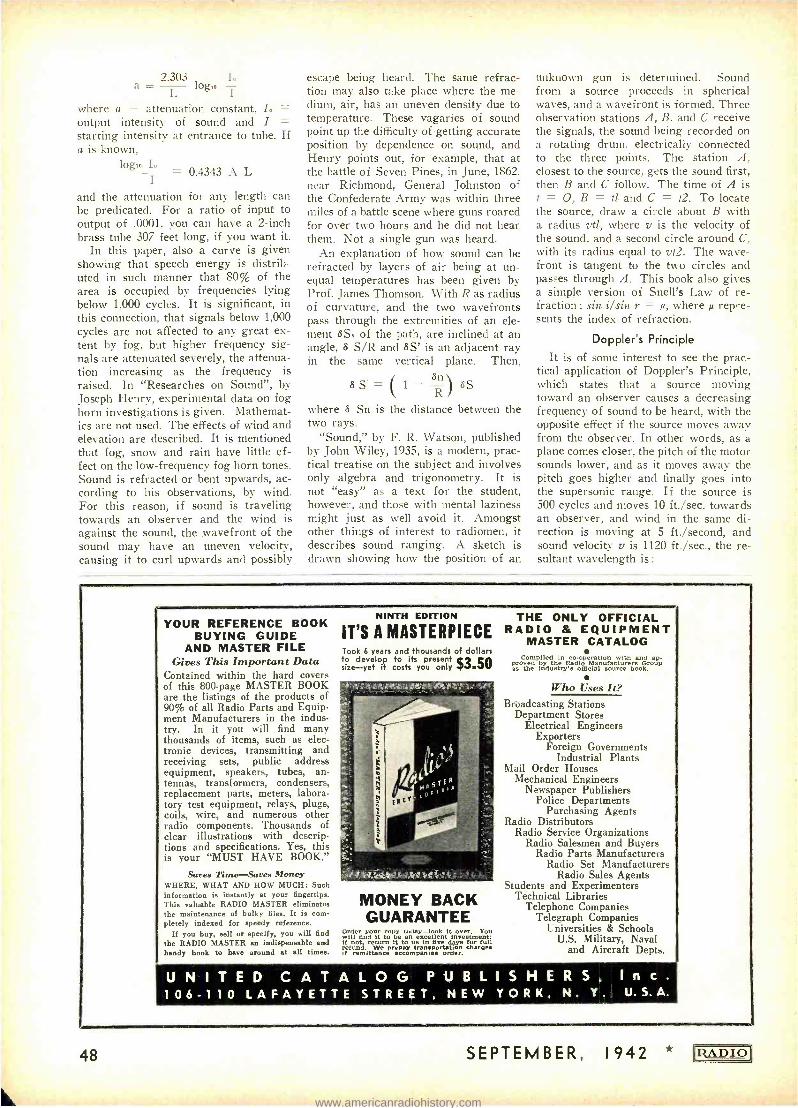
2.303 to
In
L g where a = attenuation constant, I. = output intensity of sound and I = starting intensity at entrance to tube. If a is known,
log. In = 0.4343 A L I
and the attenuation for any length can be predicated. For a ratio of input to output of .0001, you can have a 2 -inch brass tube 307 feet long, if you want it.
In this paper, also a curve is given showing that speech energy is distrib- uted in such manner that 80% of the area is occupied by frequencies lying below 1,000 cycles. It is significant, in this connection, that signals below 1,000 cycles are not affected to any great ex- tent by fog, but higher frequency sig- nals are attenuated severely, the attenua- tion increasing as the frequency is raised. In "Researches on Sound ", by Joseph Henry, experimental data on fog horn investigations is given. Mathemat- ics are not used. The effects of wind and elevation are described. It is mentioned that fog, snow and rain have little ef- fect on the low- frequency fog horn tones. Sound is refracted or bent upwards, ac- cording to his observations, by wind. For this reason, if sound is traveling towards an observer and the wind is against the sound, the wavefront of the sound may have an uneven velocity, causing it to curl upwards and possibly
escape being heard. The same refrac- tion may also take place where the me- dium, air, has an uneven density due to temperature. These vagaries of sound point up the difficulty of getting accurate position by dependence on sound, and Henry points out, for example, that at the battle of Seven Pines, in June, 1862. near Richmond, General Johnston of the Confederate Army was within three miles of a battle scene where guns roared for over two hours and he did not hear them. Not a single gun was heard.
An explanation of how sound can be refracted by layers of air being at un- equal temperatures has been given by Prof. James Thomson. With R as radius of curvature, and the two wavefronts pass through the extremities of an ele- ment SS. of the path, are inclined at an angle, S S/R and SS' is an adjacent ray in the same vertical plane. Then,
SS'= ( 1 - R) SS
where S Sn is the distance between the two rays.
"Sound," by F. R. Watson, published by John Wiley, 1935, is a modern, prac- tical treatise on the subject and involves only algebra and trigonometry. It is not "easy" as a text for the student, however, and those with mental laziness might just as well avoid it. Amongst other things of interest to radiomen, it describes sound ranging. A sketch is drawn showing how the position of an
unknown gun is determined. Sound from a source proceeds in spherical waves, and a wavefront is formed. Three observation stations A, B. and C receive the signals, the sound being recorded on a rotating drum, electrically connected to the three points. The station A, closest to the source, gets the sound first, then B and C follow. The time of A is t = O, B = tl and C = t2. To locate the source, draw a circle about B with a radius vtl, where y is the velocity of the sound, and a second circle around C, with its radius equal to vt2. The wave - front is tangent to the two circles and passes through A. This book also gives a simple version of Snell's Law of re- fraction : sin i /sin r = it, where repre- sents the index of refraction.
Doppler's Principle
It is of some interest to see the prac- tical application of Doppler's Principle, which states that a source moving toward an observer causes a decreasing frequency of sound to be heard, with the opposite effect if the source moves away from the observer. In other words, as a plane comes closer, the pitch of the motor sounds lower, and as it moves away the pitch goes higher and finally goes into the supersonic range. If the source is 500 cycles and moves 10 ft. /sec. towards an observer, and wind in the same di- rection is moving at 5 ft. /second, and sound velocity y is 1120 ft. /sec., the re- sultant wavelength is :
YOUR REFERENCE BOOK BUYING GUIDE
AND MASTER FILE Gives This Important Data
Contained within the hard covers of this 800 -page MASTER BOOK are the listings of the products of 90% of all Radio Parts and Equip- ment Manufacturers in the indus- try. In it you will find many thousands of items, such as elec- tronic devices, transmitting and receiving sets, public address equipment, speakers, tubes, an- tennas, transformers, condensers, replacement parts, meters, labora- tory test equipment, relays, plugs, coils, wire, and numerous other radio components. Thousands of clear illustrations with descrip- tions and specifications. Yes, this is your "MUST HAVE BOOK."
Saves Time -Saves Money WHERE, WHAT AND HOW MUCH: Such information is instantly at your fingertips. This valuable RADIO MASTER eliminates the maintenance of bulky files. It is com- pletely indexed for speedy reference.
If you buy, sell or specify, you will find the RADIO MASTER an indispensable and handy book to have around at all times.
NINTH EDITION
IT'S A MASTERPIECE Took 6 years and thousands of dollars to develop to its present size -yet it costs you only $3.50
MONEY BACK GUARANTEE
Order your copy wday -look it over. You will find it to be an excellent investment; if not, return It to us in five days for full refund. We prepay transportation charge if remittance accompanies order.
THE ONLY OFFICIAL RADIO & EQUIPMENT
MASTER CATALOG Compiled in co-operation with and up-
o°thé dsd®cial oOYp s nut só ciurcce book.
Who Uses It? Broadcasting Stations
Department Stores Electrical Engineers
Exporters Foreign Governments
Industrial Plants Mail Order Houses
Mechanical Engineers Newspaper Publishers
Police Departments Purchasing Agents
Radio Distributors Radio Service Organizations
Radio Salesmen and Buyers Radio Parts Manufacturers
Radio Set Manufacturers Radio Sales Agents
Students and Experimenters Technical Libraries
Telephone Companies Telegraph Companies
Universities & Schools U.S. Military, Naval
and Aircraft Depts.
U N I T E D C A T A L O G P U B L I S H E R S
106-110 LAFAYETTE STREET, NEW YORK, N. Y
I n c .
, U. S. A.
48 SEPTEMBER, 1942
www.americanradiohistory.com
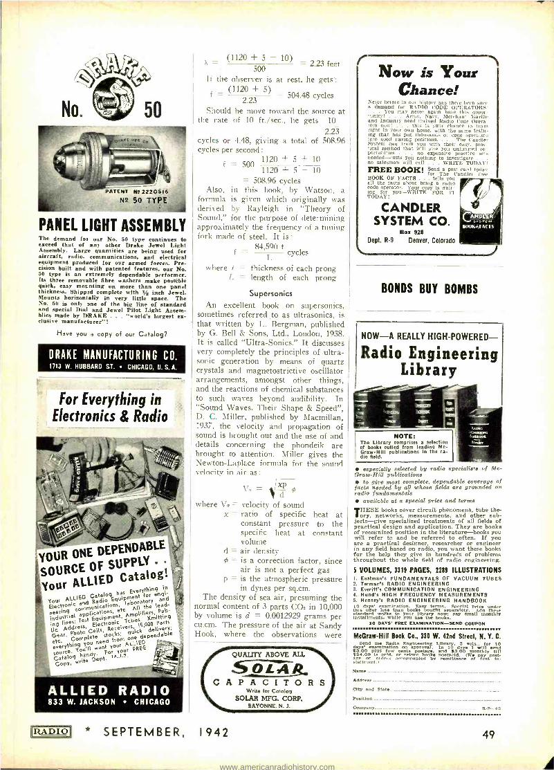
PATENT NE 2220516 N2 50 TYPE
PANEL LIGHT ASSEMBLY The demand for our No. 50 type continues to exceed that of any other Drake Jewel Light Assembly. Large quantities are being used for aircraft, radio, communications, and electrical equipment produced for our armed fortes. Pre- cision built and with patented features, our No. 50 type is an extremely dependable performer. Its three removable fibre washers make possible quick, easy mocnting on more than one panel thickness. Shipped complete with '4 inch Jewel. Mounts horizontally in very little space. The No. 50 is only one of the big line of standard and special Dial and Jewel Pilot Light Assem- blies made by DRAKE . . . "world's largest ex- clusive manufacturer"!
Have you a copy of our Catalog?
DRAKE MANUFACTURING CO. 1713 W. HUBBARD ST. CHICAGO, U.S.A.
For Everything in Electronics & Radio
YOUR ONE DEPENDABLE
SOURCE OF SUPPLY
Catalog 'Your ALLI
ED has Everything
in
Your ALLIED Catalog Equipment
for agi Electronic
and Radio aboraory
neerinri communications, applications,
etc. All the lead-
ing lines: Test Equipment, T b lifi r5. tub- industrial Pub-
lic lonic 15,000 , r 'Parts,
Gear, Photo Cells, Receivers delivers; Gear, Phots
Complete stocks; ive y
etc. Com, need from one dependable
everything want your AL' -IED r You'll For your
FREE source. handy. , -1.2. Copy, write Dept. COPY,
ALLIED RADIO 833 W. JACKSON CHICAGO
RADIO
(1120 + 5 10) = 2.23 feet 500
1f the observer is at rest, he gets: (1120 + 5) = 504.48 cycles
2.23 Should he move toward the source at
the rate of 10 ft. /sec., he gets 10
2.23 cycles or 4.48, giving a total of 508.96 cycles per second :
f = 500 1120 + 5 + 10
1120 + 5 - 10
= 508.96 cycles Also, in this hook, by Watson, a
formula is given which originally was derived by Rayleigh in "Theory of Sound," for the purpose of determining approximately the frequency of a tuning fork made of steel. It is:
f _ 84,590 t
cycles
where t = thickness of each prong L = length of each prong
Supersonics
An excellent book . on supersonics, sometimes referred to as ultrasonics, is that written by L. Bergman, published by G. Bell & Sons, Ltd., London, 1938. It is called "Ultra -Sonics." It discusses very completely the principles of ultra- sonic generation by means of quartz crystals and magnetostrictive oscillator arrangements, amongst other things, and the reactions of chemical substances to such waves beyond audibility. In "Sound Waves, Their Shape & Speed ", D. C. Miller, published by Macmillan, 1937, the velocity and propagation of sound is brought out and the use of and details concerning the phondeik are brought to attention. Miller gives the Newton -Laplace formula for the sound velocity in air as:
x vs p OS
where VD = velocity of sound x = ratio of specific heat at
constant pressure to the specific heat at constant volume
d = air density = is a correction factor, since
air is not a perfect gas is the atmospheric pressure in dynes per sq.cm.
The density of sea air, presuming the normal content of 3 parts CO2 in 10,000 by volume is d = 0.0012929 grams per cu.cm. The pressure of the air at Sandy Hook. where the observations were
p -
QUALITY ABOVE ALL
OL4 C A P A C I T O R S
Write for Catalog SOLAR MFG. CORP.
BAYONNE. N. J.
* SEPTEMBER, 1942
r Now is Your
Chance! Never before in our history has there been such a demand for RADIO CODE OPERATORS!
You may never again have this oppor- tunity! . Army, Navy, Merchant Marine and Industry need trained Radio Code Opera- tors now! . . this is your chance to train right in your own home, with the same train- ing that has put thousands of code operators into good paying positions. . The Candler System can train you with their easy, prac- tical method that will give you unlimited op- portunities . . no expensive practice sets needed --costs you nothing to investigate no salesman will call . WRITE TODAY! .
FREE BOOK! Send a post card today for The Candler free
1300K OF FACTS . tells you all the facts about being a radio rode operator. Your copy is wait- ing for you -WRITE FOR IT TODAY!
CANDLER SYSTEM CO.
Box 928 Dept. R9 Denver, Colorado
BONDS BUY BOMBS
NOW -A REALLY HIGH- POWERED-
Radio Engineering Library
1
NOTE: The Library comprises a selection of books culled from leading Mc-
f Graw -Hill publications In the ra- dio field.
especially selected by radio specialists of Mc- Graw-Hill publications
to give most complete, dependable coverage of facts needed by all whose fields are grounded on radio fundamentals
available at a special price and terms THESE books cover circuit phenomena, tube the -
ory, networks. measurements, and other sub- jects -give specialized treatments of all fields of practical design and application. They are books of recognized position in the literature -books you will refer to and be referred to often. If you are a practical designer, researcher or engineer in any field based on radio, you want these books for the help they give in hundreds of problems throughout the whole field of radio engineering.
s VOLUMES, 3319 PAGES, 2289 ILLUSTRATIONS I. Eastman's FUNDAMENTALS OF VACUUM TUBES 2. Tarmac's RADIO ENGINEERING 3. Everitt's COMMUNICATION ENGINEERING 4. Hund's HIGH FREQUENCY MEASUREMENTS 5. Henney's RADIO ENGINEERING HANDBOOK 10 days' examination. Easy terms. Special price under thin offer less than books bought separately. Ada these standard works to roar library now: pay small monthly Installments. while you use the books.
10 OATS' FREE EXAMINATION -SEND COUPON
McGraw -Hill Book Co., 330 W. 42nd Street, N. Y. C. Send me Radio Engineering Library, 5 vols., for 10 days' examination on approval. In 10 days I will Send $3.00 plus few cents postage, and $3.00 monthly till $24.00 Is peed. or return books postpaid. (We pay post- age on de, acenpanied by remittance of first In- stallment.)
m
Name
Address
City and state Position
Company R-p-42
49
www.americanradiohistory.com
COVINGTON LAPIDARY EQUIPMENT FOR QUARTZ CRYSTAL PRODUCTION
Used by the U. S. Government
it, 16 -inch LAP UNIT
4 -inch Power Feed DIAMOND SAW
Send for Literature to
COVINGTON LAPIDARY ENGINEERING CO.
Redlands, Cal
PACKED WITH VALUES!
EVERYTHING IN RADIO Sets, parts. supplies, public
address systems, amateur equip- ment, testers, kits and fluores- cent lighting at lowest prices. Huge stocks, bought months ago
.. ready for shipment the same day your order is received. The Defense`Program is making big demands on our industry but be- cause of our advance buying we are able to fill your orders promptly and efficiently.
BURSTEIN- APPLEBEE COMPANY 1012 -14 McGEE STREET, KANSAS CITY, MISSOURI
Advertising Index Aerovox Corp 47 Allied Radio Corp 49 Astatic Corp 37 Bliley Electric Co 41
Bud Radio, Inc 47
Burstein -Applebee Co 50 Candler System Co 49 Centralab 34 Covington Lapidary Eng. Co 50
Drake Mfg. Co 49 Echophone Radio Co 29 Eitel- McCullough, Inc 31
Guardian Electric Co 38 Hallicrafters Co., The 3, 4
Henry 'Radio Shop 39
Hytron Corp Cover 4
Jensen Radio Mfg. Co 8
Mallory & Co., P. R 40 McGraw -Hill Book Co., Inc 49 Meissner Mfg. Co 33
National Co., Inc Cover 3
National Union Radio Corp 45
Ohmite Mfg. Co 42 Pioneer Gen -E -Motor 42 Polk & Co., R. L ' 50 Radio Magazines, Inc 43, 46 Raytheon Mfg. Co 9
Shure Brothers 35
Solar Mfg. Co 49 Thordarson Electric Mfg. Co 45 Triplett Elec. Inst. Co 6
United Catalog Publishers, Inc.__48
United Transformer Co Cover 2
U.S. Army Signal Corps 44 Utah Radio Products Co 36
50
made was p = 76 8g where 8 is the den- sity of mercury and g is the acceleration due to gravity. The value of 8 is 13.5951 grams per cu.cm., the calculation being made for dry air at 0 degrees Centigrade under 76 cm. mercury pressure. Then, g = 980.212, x = 1.4029, 95 = 0.998930 and V. = 331.36 meters per second at 0° C.
He gives other interesting facts ; for example, thunder is seldom heard at a distance of greater than ten miles, al- though when Krakatoa, a volcano lying off Java and Sumatra blew up in August 1833, the sound was heard 3,000 miles away and traveled several times around the earth, being recorded on instruments. This shows that the range is proportion- al, amongst other things, to the intensity of the disturbance. The velocity of the wave is,
V= ä Where V = velocity
e = elasticity of medium through which wave passes
d = density of medium From this we can see that increasing
the density will decrease the sound velo- city, and if wé put a thick wall between a source of sound and an observer, the sound is cut down in velocity and takes longer to get through. The velocity of sound, in a steel rod is 5,000 meters /sec. or 16,410 ft. /sec., and in water at 13 °C. it is 1,437 meters /sec. or 4,715 ft. /sec.
The intensity of sound, energy of mo- tion, is measured by the energy that is transmitted through 1 sq. cm. of surface. The energy per cu. cm. in a sound wave depends on the density of the medium d, the square of the frequency of vibration
the square of the amplitude a', and it is expressed by the formula :
e =2 Tr' _dn'a°
It has been found by Rayleigh that when the amplitude of vibration of the air par- ticles is as small as 1 /1,000,000 milli- meter, the sound is barely audible. An amplitude as great as 1 mm. would occur only in the very loudest sounds. The in- tensity will vary inversely as the square of the distance between source and ob- server. The interpretation of these for- mulas, however, must take into consid- eration other facts. For example in the above formula, one term, n', would make it appear that as the frequency is in- creased the wave would be more intense. This does not take into account the at- tenuation- above 1,000 cycles of sound in fog, for example, and it is such things as this which you must be on the alert to catch when dealing with any formula.
GET OUR FREE
REFERENCE BOOKamt MAILING
LIST CATALOG
Gives counts and prices on accurate guaranteed mailing lists of all classes of business enter- prises in the U. S. Wholesalers -Retailers -- Manufacturers by classification and state. Also hundreds of selections of individuals such as professional men, auto owners, income lists, etc.
Write today for your copy
R. L. POLK & CO Polk Bldg.- Detroit, Mich.
Branches in Principal Cities World's Largest City Directory Publishers Mailing List Compilers. Business Statis- tics. Producers of Direct Mail Advertising.
HALF PRICE SUBSCRIPTIONS . . e
for Men in the U. S. Armed Services
Subscriptions to "RADIO" addressed to men in the U. S. Army, Navy,
Marine Corps, or Coast Guard will be accepted at the below -cost rate
of $1.50 per year. Subscriptions at this rate (whether ordered by the
addressee or a donor) should be accompanied by a remittance in full ;
addressee's rank and military address must be given. This rate applies
wherever domestic U. S. postal service extends, including naval units
at sea and overseas army postoffices. No cancellations or refunds.
Simply write rank, name, and military address on a slip of paper and
send, accompanied by remittance, to
Radio Magazines, Inc., 132 W. 43rd St., New York, N.Y.
PRINTED IN U-S* SEPTEMBER, 1942 RADIO)
www.americanradiohistory.com


![PERFORMANCE, EMISSION, AND COMBUSTION ......tion pressure. Alptekin et al.[2] tested the effect on engine performance, combustion charac-teristics, and exhaust emissions of using waste](https://img.pdfslide.us/doc/110x75/5fe4282d8c8e9c10e8526db6/performance-emission-and-combustion-tion-pressure-alptekin-et-al2.jpg)


![Article2Fs11434...tive, chemically stable, economical and non-toxic charac-teristics [1–4]. However, the restricted visible-light absorp-tion limits its development, which drives](https://img.pdfslide.us/doc/110x75/5e8a3cf5befcd73cbd23bf6d/article-2fs11434-tive-chemically-stable-economical-and-non-toxic-charac-teristics.jpg)