Embed Size (px)
Citation preview

Broadband Faraday Isolator
Broadband ISO Series User’s Manual
ii Preface
Warranty
Newport Corporation warrants that this product will be free from defects in material and
workmanship and will comply with Newport’s published specifications at the time of sale for a
period of one year from date of shipment. If found to be defective during the warranty period,
the product will either be repaired or replaced at Newport's option.
To exercise this warranty, write or call your local Newport office or representative, or contact
Newport headquarters in Irvine, California. You will be given prompt assistance and return
instructions. Send the product, freight prepaid, to the indicated service facility. Repairs will be made
and the instrument returned freight prepaid. Repaired products are warranted for the remainder of
the original warranty period or 90 days, whichever is longer.
Limitation of Warranty
The above warranties do not apply to products which have been repaired or modified without
Newport’s written approval, or products subjected to unusual physical, thermal or electrical
stress, improper installation, misuse, abuse, accident or negligence in use, storage, transportation
or handling. This warranty also does not apply to fuses, batteries, or damage from battery
leakage.
THIS WARRANTY IS IN LIEU OF ALL OTHER WARRANTIES, EXPRESSED OR
IMPLIED, INCLUDING ANY IMPLIED WARRANTY OF MERCHANTABILITY OR
FITNESS FOR A PARTICULAR USE. NEWPORT CORPORATION SHALL NOT BE
LIABLE FOR ANY INDIRECT, SPECIAL, OR CONSEQUENTIAL DAMAGES
RESULTING FROM THE PURCHASE OR USE OF ITS PRODUCTS.
First printing 2005
© 2005 by Newport Corporation, Irvine, CA. All rights reserved. No part of this manual may be
reproduced or copied without the prior written approval of Newport Corporation.
This manual has been provided for information only and product specifications are subject to
change without notice. Any change will be reflected in future printings.
Newport Corporation
1791 Deere Avenue
Irvine, CA, 92606 USA
P/N 90025451 Rev. A

iii Preface
Technical Support Contacts
North America & Asia Europe
Newport Corporation Service Dept. Newport/MICRO-CONTROLE S.A.
1791 Deere Ave. Irvine, CA 92606 Zone Industrielle
Telephone: (949) 253-1694 45340 Beaune la Rolande, France
Telephone: (800) 222-6440 x31694 Telephone: (33) 02 38 40 51 56
Asia
Newport Opto-Electronics Technologies
253 Aidu Road, Bld #3, Flr 3, Sec C,
Shanghai 200131, China
Telephone: +86 21 5046 2300
Telephone: +86 21 5046 2323
Newport Corporation Calling Procedure
If there are any defects in material or workmanship or a failure to meet specifications, promptly notify
Newport's Returns Department by calling 1-800-222-6440or by visiting our website at
www.newport.com/returns within the warranty period to obtain a Return Material Authorization
Number (RMA#). Return the product to Newport Corporation, freight prepaid, clearly marked with the
RMA# and we will either repair or replace it at our discretion. Newport is not responsible for damage
occurring in transit and is not obligated to accept products returned without an RMA#.
E-mail: [email protected]
When calling Newport Corporation, please provide the customer care representative with the following
information:
Your Contact Information
Serial number or original order number
Description of problem (i.e., hardware or software)
To help our Technical Support Representatives diagnose your problem, please note the following
conditions:
Is the system used for manufacturing or research and development?
What was the state of the system right before the problem?
Have you seen this problem before? If so, how often?
Can the system continue to operate with this problem? Or is the system nonoperational?
Can you identify anything that was different before this problem occurred?

iv Preface
Table of Contents
Warranty ..................................................................................................... ii
Technical Support Contacts ....................................................................... iii
Table of Contents ....................................................................................... iv
1 General Information 1
1.1 Introduction ............................................................................................1
1.2 Safe Use of Your Newport Faraday Isolator ..........................................2
1.3 Operation ................................................................................................4
1.3.1 The Newport Broadband Faraday Isolator ................................4
1.3.2 Using your Faraday Isolator ......................................................6
1.3.3 Tuning your Faraday Isolator ....................................................7
1.4 Specifications .........................................................................................7
2 Factory Service Information 9
2.1 Service Form ..........................................................................................9
1
1 General Information
1.1 Introduction
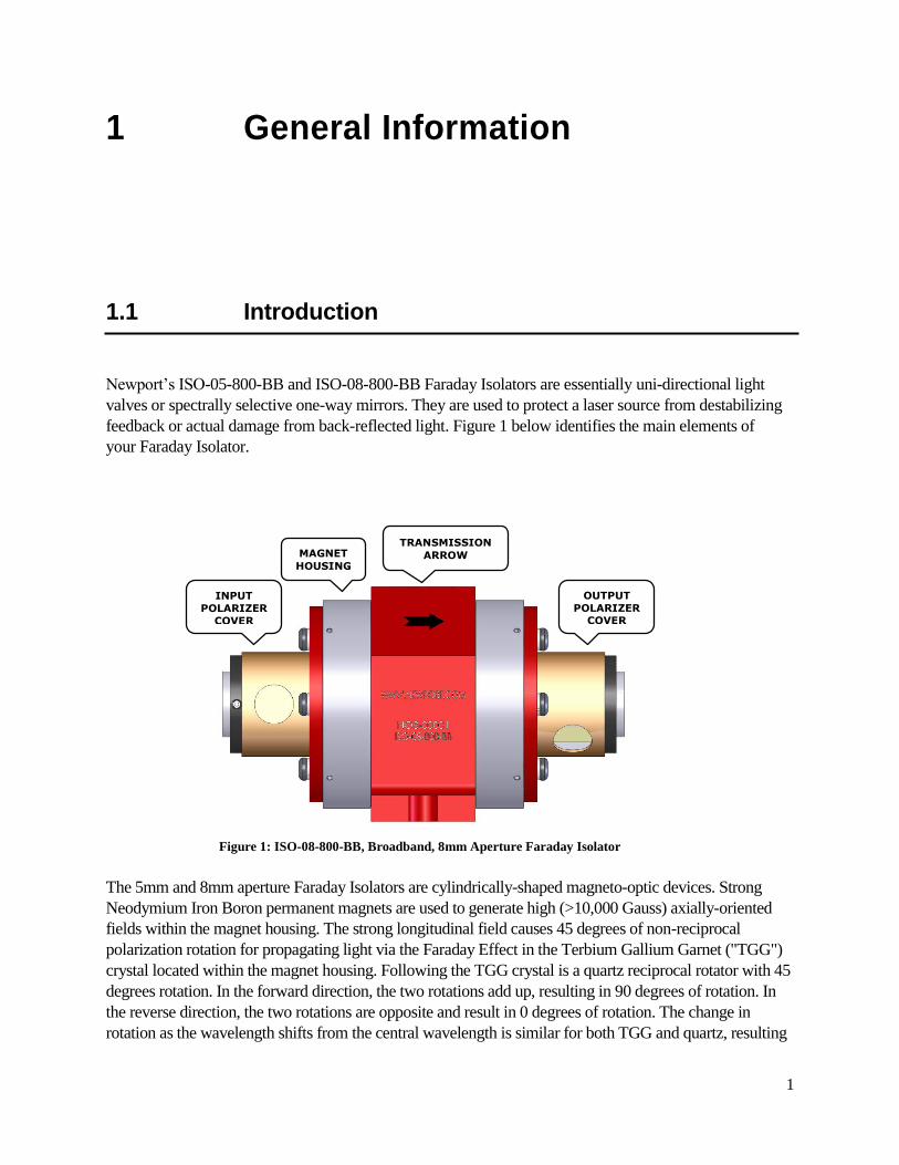
Newport’s ISO-05-800-BB and ISO-08-800-BB Faraday Isolators are essentially uni-directional light
valves or spectrally selective one-way mirrors. They are used to protect a laser source from destabilizing
feedback or actual damage from back-reflected light. Figure 1 below identifies the main elements of
your Faraday Isolator.
The 5mm and 8mm aperture Faraday Isolators are cylindrically-shaped magneto-optic devices. Strong
Neodymium Iron Boron permanent magnets are used to generate high (>10,000 Gauss) axially-oriented
fields within the magnet housing. The strong longitudinal field causes 45 degrees of non-reciprocal
polarization rotation for propagating light via the Faraday Effect in the Terbium Gallium Garnet ("TGG")
crystal located within the magnet housing. Following the TGG crystal is a quartz reciprocal rotator with 45
degrees rotation. In the forward direction, the two rotations add up, resulting in 90 degrees of rotation. In
the reverse direction, the two rotations are opposite and result in 0 degrees of rotation. The change in
rotation as the wavelength shifts from the central wavelength is similar for both TGG and quartz, resulting
TRANSMISSION
ARROW MAGNET
HOUSING
OUTPUT
POLARIZER COVER
INPUT
POLARIZER
COVER
Figure 1: ISO-08-800-BB, Broadband, 8mm Aperture Faraday Isolator
2
in broadband operation. In operation, the magnet housing is sandwiched between input and output
polarizers that have their transmission axis oriented 90 degrees relative to each other. In the reverse
direction the backward traveling beam has a polarization orthogonal to the input polarizer and is
therefore crossed with it, resulting in a rejected beam exiting the input polarizer.
1.2 Safe Use of Your Newport Faraday Isolator
The operational hazards presented to operating personnel by the use of your Newport Faraday
Isolator are listed below. An explanation of how the Faraday Isolator is designed, together with
procedures users can employ to eliminate or minimize these hazards are also listed.
1. Danger of sharp ferromagnetic objects being attracted to the residual permanent
magnet fields outside of the isolator. This hazard is of most concern if such fields
cause flying objects when being handled.
Your Newport Faraday Isolator requires strong internal magnetic fields to operate
properly. Efforts have been made to minimize external fields from the device while still
maintaining a relatively small and cost effective package. The external fields are designed
to be well within federal safety guidelines which limit external fields from magnetic
devices to be less than 2K Gauss at a radial distance of 5cm from the outside of the
device. However, such fields can be sufficient to attract nearby objects such as knives and
razor blades. Should attraction of such objects begin to occur there would be a strong
attractive force directing these objects towards the interior of the magnet housing. This
could be likely to result in injury (e.g. a cut or puncture wound) if such attraction
occurred while the device was being handled – particularly if a body part of the operating
personnel is near a beam Aperture (i.e. end) of the device.
To minimize the above risks remove all loose ferromagnetic objects from the path
over which your Newport Faraday Isolator is to be moved prior to attempting to
move it. Do not pick up the isolator by its ends (i.e. apertures) where the attractive
magnetic fields are strongest. Always pick the isolator up along its sides.
2. Reflection of rejected beams from the input and output polarizer.
The polarizer covers have been positioned at the factory to block all beams rejected
from the polarizers. In the event that your Faraday Isolator will be used with
transmitted average powers in excess of 25W, or will block backward propagating
light in excess of 0.5W average power, these polarizer covers must be rotated to allow
rejected beams to exit (see Figure 1) onto user supplied beam dumps. These rejected
beams can represent a hazard to users and/or their colleagues. Care must be
exercised to ensure that all rejected beams (both transmission and isolation
directions) are accounted for and terminated into functional beam dumps.
3
Wherever possible keep the strongest rejected beams in the horizontal plane of the
table or otherwise safest direction (typically down into the table). Always wear laser
safety glasses/goggles consistent with all laser frequencies and power levels
present. See the following sections for further details.
3. Failure of operating personnel to observe standard laser safety by sighting down
through the isolator when laser radiation is present.
The optical elements within the Newport Faraday Isolators can be transmissive
throughout the visible and near infrared. Consequently it is never appropriate to view
through the device in either the transmission or isolation direction when laser radiation
is present – even with laser safety goggles.
Never sight through your Newport Faraday Isolator in either direction when
there is any possibility of laser radiation being present.
4. Harm caused by external magnetic fields.
Your Newport Faraday Isolator has been designed to meet existing federal safety
guidelines for external fields as noted previously. Such guidelines could change in the
future as more information becomes known or reviewed regarding the interaction
between magnetic fields and human health. Since there exist various claims regarding
the potential harmful (and beneficial!) effects of magnetic fields on humans it is prudent
to limit interaction with these fields as much as possible.
Personnel with any magnetically-sensitive implants such as pacemakers should
consult their medical doctor regarding any potential complications which could
arise from the isolator external magnetic fields.
5. Other non-health related hazards.
The Faraday Isolator external magnetic fields can draw ferromagnetic objects into the
magnet housing that can damage the optical elements within the device. Keep a suitable
area in all directions around the Faraday Isolator clear of any loose ferromagnetic objects.
Ideally, use non-magnetic tools (such as stainless steel or titanium) and hardware to
secure the Faraday Isolator. If only ferromagnetic tools are available use extreme care
when using them around the Faraday Isolator. It is always helpful to bring such tools
towards an aperture (or end) radially rather than along the optical beam path. Doing this
ensures that the fields will tend to pull such objects into the magnet housing endplate
rather than into the optical aperture. Where possible use two hands, one to hold the tool
and the other to guide it to the desired destination.
Another concern regarding external magnetic fields is their effect on
magnetically-sensitive devices. The external fields are strong enough to induce a
pulse of current in electronic devices (such as digital watches) that can destroy them.
The fields can also disrupt the operation of other mechanical devices with
4
ferromagnetic parts in them. Finally, the external fields can erase information from
magnetic strips such as are found on credit and ID cards. Remove all magnetically-
sensitive materials and devices such as watches, computer hard drives and magnetic
strips from operators prior to working in the proximity of an isolator.
1.3 Operation
1.3.1 The Newport Broadband Faraday Isolator
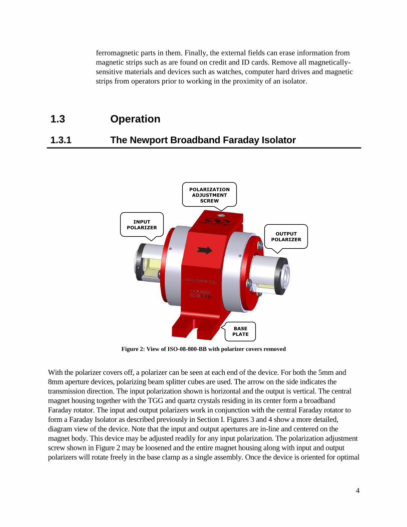
Figure 2: View of ISO-08-800-BB with polarizer covers removed
With the polarizer covers off, a polarizer can be seen at each end of the device. For both the 5mm and
8mm aperture devices, polarizing beam splitter cubes are used. The arrow on the side indicates the
transmission direction. The input polarization shown is horizontal and the output is vertical. The central
magnet housing together with the TGG and quartz crystals residing in its center form a broadband
Faraday rotator. The input and output polarizers work in conjunction with the central Faraday rotator to
form a Faraday Isolator as described previously in Section I. Figures 3 and 4 show a more detailed,
diagram view of the device. Note that the input and output apertures are in-line and centered on the
magnet body. This device may be adjusted readily for any input polarization. The polarization adjustment
screw shown in Figure 2 may be loosened and the entire magnet housing along with input and output
polarizers will rotate freely in the base clamp as a single assembly. Once the device is oriented for optimal
OUTPUT
POLARIZER
INPUT
POLARIZER
BASE
PLATE
E
POLARIZATION
ADJUSTMENT
SCREW
5
input polarization, the screw is tightened again. Further details for this procedure are provided in section
1.3.3.
The input view is observed in Figure 1. Note that the polarizer covers are in the open position here,
allowing rejected beams to exit the device. The user may close these ports by simply rotating the polarizer
cover, shown in Figure 1, until the port is in the closed position. This cover is held in place by an O-ring
located between its inner surface and the polarizer mount.
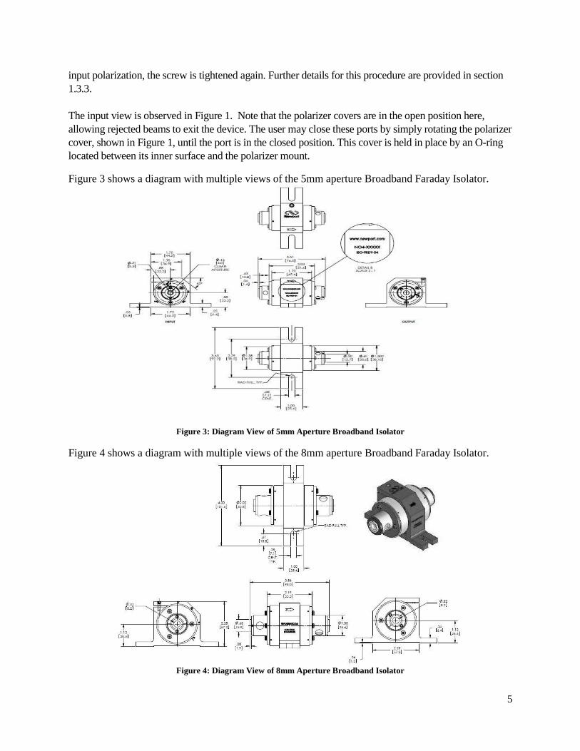
Figure 3 shows a diagram with multiple views of the 5mm aperture Broadband Faraday Isolator.
Figure 3: Diagram View of 5mm Aperture Broadband Isolator
Figure 4 shows a diagram with multiple views of the 8mm aperture Broadband Faraday Isolator.
Figure 4: Diagram View of 8mm Aperture Broadband Isolator

6
1.3.2 Using your Faraday Isolator
Observe the guidelines for safe use of your Faraday Isolator found in Section 1.2 above when
removing your isolator from its shipping container. Do not remove the protective dust-cover end caps
from the polarizers until the device is in a clean, relatively dust-free environment. Save the protective
end caps, packaging material and containers in the event that the device should ever need to be
returned to Newport.
Verify that the Input and Output polarization states are consistent with the intended mode of
operation. If not, re-adjust the isolator as required (see Section 1.3.3).
With the source laser off, or running at very low power (less than 100mW), position the Faraday
Isolator such that the source laser beam can be directed through the Input Aperture.
Critical alignment of the Faraday Isolator should be done at low power (less than 100mW) in order to
prevent optical damage to your isolator or laser source.
Use IR cards or viewers to ensure that the source laser beam is centered on the input and output
apertures. The clear aperture of these devices is either 5mm or 8mm, centered on the circular cross
section of the magnet body. There are different mounting options for establishing appropriate beam
height. It is also preferable to use an IR viewer to ensure that weak reflections from AR coated optical
surfaces in the Faraday Isolator are not being directed back into the source laser. The optical surfaces in
the Faraday Isolator are angled slightly to reduce these reflections. Increasing the distance between the
Faraday Isolator and the source laser can also help ensure that no reflections couple back into the source
laser if necessary. Alternatively, if the beam used is smaller than the aperture of the device by a
reasonable margin, the device may be slightly tilted.
At this point the Faraday Isolator should be secured to the work surface with two to four 1/4 - 20 or
M6 screws – one for each slot in the baseplate flanges. Steel (ferromagnetic) ball drivers or other
such wrenches will be attracted to the external magnetic field surrounding the device. If possible use
anti-magnetic stainless steel or titanium tools. If ferromagnetic tools are used it is desirable to
introduce them slowly toward the device from the sides along the direction of the baseplate flange
slots.
If the Faraday Isolator will be used with average powers in excess of 25W transmitted or 0.5W rejected
backward propagating radiation the Polarizer Covers will need to be removed so that the Escape Ports
allow rejected polarization light to be safely dumped onto a beam dump. Failure to allow these rejected
polarizations to escape can cause the device to heat up. Such heat can degrade the performance of the
Faraday Isolator, or in severe cases, cause damage to optical components in the isolator. While
working with low alignment level power and wearing safety glasses, remove the screw holding the
dust cover in place for both the input and output. Any rejected polarized beams (in either the forward
or backward propagating directions) can now exit the polarizer assembly. Use an IR viewer or IR card
to locate these beams. Ensure that they are terminated on beam dumps consistent with the maximum
amount of power that may be in such beams. If the Faraday Isolator is used in applications where
strong reflections and/or optical gain elements (amplifiers) exist there may be very high power rejected
7
beams for backward propagating light at the input polarizer. If the average power levels used do not
exceed 25W transmitted or 0.5W of backward propagating power then the Polarizer Covers may be
kept in their factory positioned orientation – that is with all rejected beams blocked by the Polarizer
Cover. However, if the Faraday Isolator is to be used with very high peak intensities it is prudent to
allow rejected beams to escape on to external beam dumps to prevent any ablation damage to the
nickel-plated Polarizer Covers. Follow the same procedure above as for high average powers in order
to safely terminate all rejected beams.
1.3.3 Aligning your Faraday Isolator
For both the 5mm and 8mm aperture devices, the cylindrical magnet body is clamped into the base
clamp structure. The polarization adjustment screw may be loosened and the cylindrical isolator
structure rotates freely inside the clamp. The preferred method for alignment is to use an external
polarizer mounted to a fine rotation stage with known directional axes and a waveplate to rotate the
polarization before entering the test polarizer. By crossing this polarizer with the input polarizer of the
device, a precise input polarization may be realized to a known reference orientation. (Note: the
adjustment of the output polarizer must be 90 degrees from the input polarizer.) For more details, please
contact Newport’s technical sales department at [email protected].
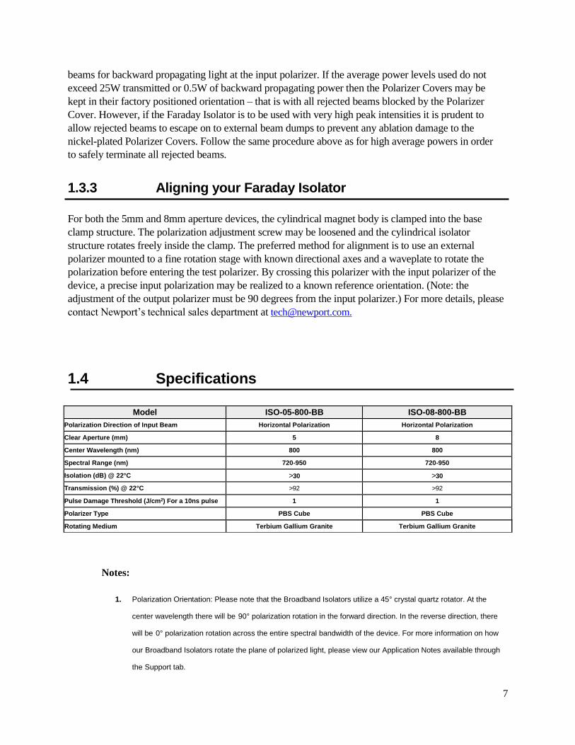
1.4 Specifications
Notes:
1. Polarization Orientation: Please note that the Broadband Isolators utilize a 45° crystal quartz rotator. At the
center wavelength there will be 90° polarization rotation in the forward direction. In the reverse direction, there
will be 0° polarization rotation across the entire spectral bandwidth of the device. For more information on how
our Broadband Isolators rotate the plane of polarized light, please view our Application Notes available through
the Support tab.
Model ISO-05-800-BB ISO-08-800-BB
Polarization Direction of Input Beam Horizontal Polarization Horizontal Polarization
Clear Aperture (mm) 5 8
Center Wavelength (nm) 800 800
Spectral Range (nm) 720-950 720-950
Isolation (dB) @ 22°C >30 >30
Transmission (%) @ 22°C >92 >92
Pulse Damage Threshold (J/cm2) For a 10ns pulse 1 1
Polarizer Type PBS Cube PBS Cube
Rotating Medium Terbium Gallium Granite Terbium Gallium Granite

8
2. Dispersion: Some pulse broadening does occur when using Newport's Broadband Isolator. Use the
following Sellmeier Equation:
3. Operating and Storage Temperature: Performance of Newport's Broadband Isolators is related to
operating temperature.
9
Newport Corporation U.S.A. Office: 800-222-6440
FAX: 949/253-1479
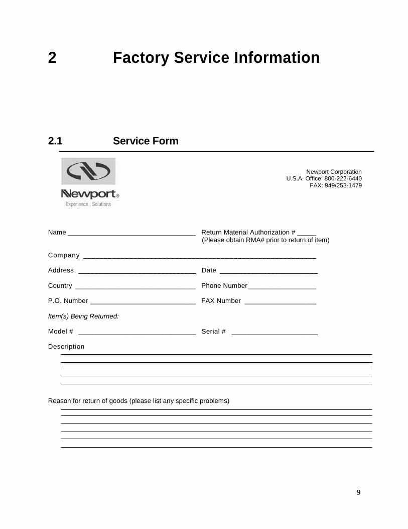
2 Factory Service Information
2.1 Service Form
Name __________________________________ Return Material Authorization # _____
(Please obtain RMA# prior to return of item)
Company ________________________________________________________
Address ______________________________ Date _________________________
Country ________________________________ Phone Number __________________
P.O. Number ____________________________ FAX Number ___________________
Item(s) Being Returned:
Model # ______________________________ Serial # ______________________
Description
Reason for return of goods (please list any specific problems)

Notes: