Embed Size (px)
Citation preview
National Aeronautics and Space Administration
Bringing Home the Future
The Annual Report of the 2011
NASA Inventions & Contributions Board (ICB)
2
Index
Foreword Dr. Michael G. Ryschkewitsch, Chair, NASA Chief Engineer
Introduction The ICB Mission
Background Where the ICB comes in
Performance 2011 Awards Statistics and Metrics
Exceptional Cases:
Yearly Competitions: Software and Invention of the Year
Additional Exceptional Cases
The Board and Staff Making recognition happen for NASA
On the Cover: Historic Landing for Shuttle Atlantis
At 5:57 a.m. EDT on July 21, 2011, space shuttle Atlantis landed for the final time at NASA's Kennedy Space Center after 200 orbits around Earth and a journey of 5,284,862 miles on the STS-135 mission and final flight for the Space Shuttle Program.
Photo credit: NASA/Kim Shiflett
3
Message from the Chair 2011 has been a year of great change for NASA. We successfully retired the Space Shuttles after 30 years of spaceflight this year. Now we are taking the innovations and lessons that came from that program to develop an even better launch vehicle for the future. For fiscal year 2012, I asked the ICB to take a hard look at our processes and improve the objectivity and visibility of our scoring procedures. With the help of the NASA Office of the Chief Technologist, we aligned our selection criteria to ensure we appropriately recognize revolutionary game changing innovations without neglecting the more evolutionary innovations we need to keep the Agency steadily moving forward.
Dr. Michael G. Ryschkewitsch, Chair NASA Chief Engineer
4
Introduction: The ICB Mission With a mission as unique as NASA itself, The NASA Inventions and Contributions Board stands alone within the Federal Government as an organization dedicated to routinely recognizing aerospace inventors. It is comprised of researchers and engineers individually nominated by each of the ten Field Centers and confirmed by the Administrator to bring the expertise needed to appreciate and evaluate the unique technologies submitted for consideration. It is authorized to approve awards up to $100,000 from NASA and its industry partner without special congressional notification. With the help of its staff, legal counsel, and Award Liaison Officers at each Field Center, the Board reviews and valuates aerospace contributions to the government and the nation. These inventions and contributions are the result of investments in the Nation’s future in the form of aerospace research. They are the technologies needed to help humanity explore the universe and improve life here on earth. The ICB approved 2496 individual cash awards totaling nearly $1.5 million dollars this year.
Background – Where the ICB comes in When Congress created NASA from the National Advisory Committee of Aeronautics (NACA) with the signing into law of the Space Act of 1958, it tasked NASA with recognizing those who brought about scientific and technical aerospace innovation. Well over one hundred thousand awards to NASA sponsored inventors have been distributed. Previous annual reports with details on the most notable of these technologies are archived online at http://www.nasa.gov/offices/oce/icb/Annual_Report.html . The Office of the Chief Engineer and the Office of the General Counsel (OGC) team up with the ICB to select NASA’s Invention of the Year (IOY). Winners can potentially be named as IOY’s in Government and/or Commercial categories each year. The ICB also partners with the Office of Safety and Mission Assurance (OSMA) and the Chief Information Officer (OCIO) to conduct the NASA Software of the Year (SOY) Competition. (see http://www.nasa.gov/offices/oce/icb/Yearly-Comps.html ).
5
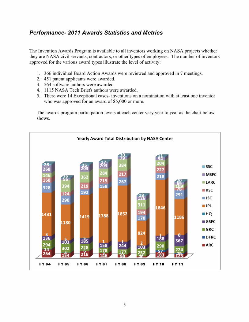
Performance- 2011 Awards Statistics and Metrics The Invention Awards Program is available to all inventors working on NASA projects whether they are NASA civil servants, contractors, or other types of employees. The number of inventors approved for the various award types illustrate the level of activity:
1. 366 individual Board Action Awards were reviewed and approved in 7 meetings. 2. 451 patent applicants were awarded. 3. 564 software authors were awarded. 4. 1115 NASA Tech Briefs authors were awarded. 5. There were 14 Exceptional cases- inventions on a nomination with at least one inventor
who was approved for an award of $5,000 or more. The awards program participation levels at each center vary year to year as the chart below shows.
6
Exceptional ICB Award Cases Each year, several ICB award applications result in at least one awardee receiving $5000 and are designated as Exceptional Awards. These Exceptional Awards must go to the NASA Administrator for approval prior to payment. The following descriptions of the Exceptional Board cases for 2011 are identified by a unique tracking code which consists of a three letter code designating the lead NASA Center for its development and a five digit number assigned to it at the time it was reported to NASA. The lead NASA Center code definitions are: Ames Research Center: ARC Dryden Flight Research Center: DFRC or DRC Glenn Research Center: GRC or LEW (formerly Lewis Research Center) Goddard Space Flight Center: GSC or GSFC Kennedy Space Center: KSC Langley Research Center: LaRC or LAR Jet Propulsion Laboratory: JPL or NPO (formerly NASA Pasadena Office) Johnson Space Center: JSC or MSC (formerly Manned Spaceflight Center) Marshall Space Flight Center: MSFC or MFS Stennis Space Center: SSC Headquarters: HQ Yearly Competitions: 2010 Invention of the Year (IOY) This distinguished competition is sponsored by the NASA Office of the General Counsel to underscore the significance of the NASA Patenting Program. The competition is held after the eligibility period is concluded, thus the 2010 IOY competition was held in 2011. The Agency can present IOY awards in two categories: (1) the NASA Commercial Invention of the Year and (2) the NASA Government Invention of the Year (if the NASA General Counsel determinates they are warranted). Each Center may submit a maximum of two technologies as long as they have at least one NASA civil servant inventor on the issued patent. In the event of multiple submissions, all nominations are considered for both award categories. The ICB may elect to recommend awards for one, both, or neither category if the circumstances warrant it. The ICB and the Office of the General Counsel selected both Commercial and Government Inventions of the Year for 2010. The eligibility requirements for the NASA Commercial Invention of the Year Award are linked to the National Inventor of the Year event promoted by the Intellectual Property Owners Educational Foundation (IPOEF), which the Commercial Invention of the Year may be nominated to. Only inventions that were commercialized to non-government customers from four years (2007-2010) prior to and including the competition year can be considered.
7
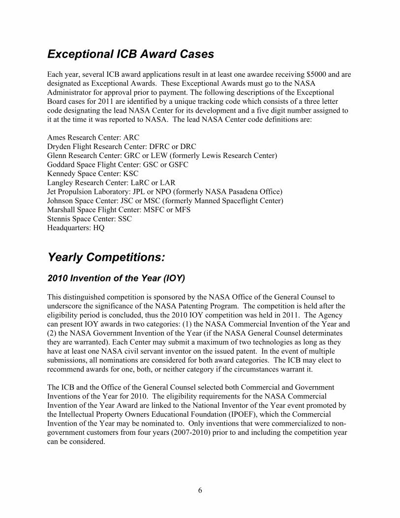
The eligibility requirements for the NASA Government Invention of the Year are based on the impact the nominated inventions have had on NASA’s mission and in other government programs. While commercial sales may exist, the deciding factor for the Government Invention of the Year Award is the value of the Government uses of the chosen nomination. The NASA Government Invention of the Year Award for 2010 was conferred upon ARC-14653-1: Future ATM Concepts Evaluation Tool (FACET). This software provides the simulation environment needed for evaluation of novel ATM (Air Traffic Management) concepts. ATM concepts include air traffic control and traffic flow management concepts. To provide a test bed for these concepts, the FACET system consists of databases, algorithms and a graphical user interface. The databases contain geometry data of the airspace including the low, high and super-high sectors within the United States. The airway definitions, positions of navigation aids and fixes, and locations of airports are provided in the geometric database. FACET also contains an aircraft performance database and an equivalence list that maps all aircraft to this database.
Figure 1: ACET integrates weather and air traffic information, which enables researchers to simulate the effect of rerouting flights for safety and timeliness.
FACET reads track data, flight plans and schedule data from the Federal Aviation Administration's Enhanced Traffic management System to create a dynamic flight database. It also reads weather data provided by the National Weather Service. To simulate and evaluate various concepts, FACET can generate realistic air traffic and can also forecast the future traffic using information from the databases. Both the trajectory simulation and prediction functions use heading, airspeed and altitude-rate dynamics along with the round-earth kinematic equations of motion. The data generated by the application algorithms are visualized using the menu-driven graphical user interface. FACET can be run in synchronous mode in which a fixed correlation between the display time and clock time is maintained or asynchronous mode in which the display is updated soon after the computations are done. The user interface also provides the means to control the various functions of FACET.
8
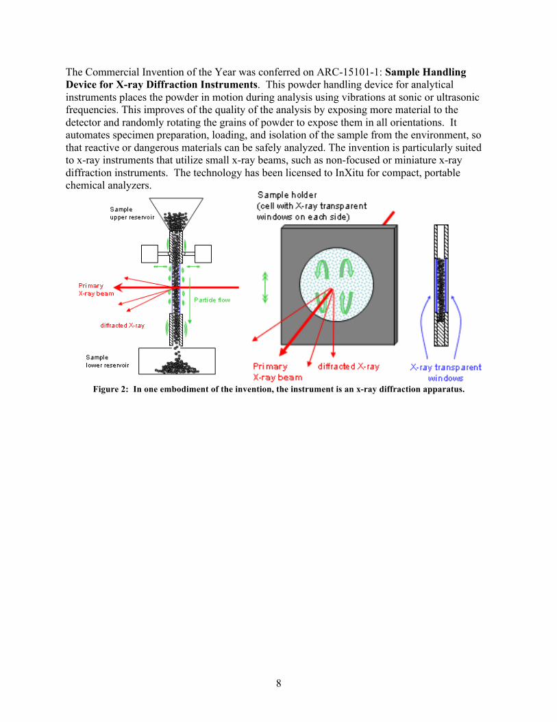
The Commercial Invention of the Year was conferred on ARC-15101-1: Sample Handling Device for X-ray Diffraction Instruments. This powder handling device for analytical instruments places the powder in motion during analysis using vibrations at sonic or ultrasonic frequencies. This improves of the quality of the analysis by exposing more material to the detector and randomly rotating the grains of powder to expose them in all orientations. It automates specimen preparation, loading, and isolation of the sample from the environment, so that reactive or dangerous materials can be safely analyzed. The invention is particularly suited to x-ray instruments that utilize small x-ray beams, such as non-focused or miniature x-ray diffraction instruments. The technology has been licensed to InXitu for compact, portable chemical analyzers.
Figure 2: In one embodiment of the invention, the instrument is an x-ray diffraction apparatus.
9
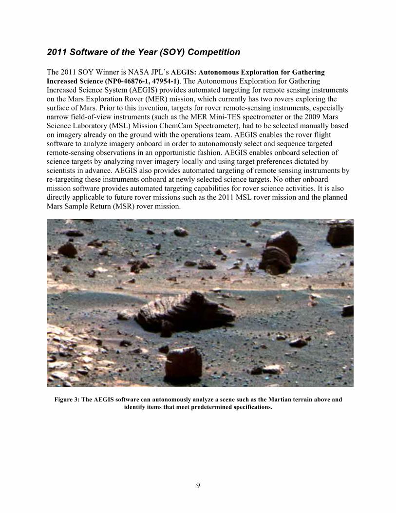
2011 Software of the Year (SOY) Competition The 2011 SOY Winner is NASA JPL’s AEGIS: Autonomous Exploration for Gathering Increased Science (NP0-46876-1, 47954-1). The Autonomous Exploration for Gathering Increased Science System (AEGIS) provides automated targeting for remote sensing instruments on the Mars Exploration Rover (MER) mission, which currently has two rovers exploring the surface of Mars. Prior to this invention, targets for rover remote-sensing instruments, especially narrow field-of-view instruments (such as the MER Mini-TES spectrometer or the 2009 Mars Science Laboratory (MSL) Mission ChemCam Spectrometer), had to be selected manually based on imagery already on the ground with the operations team. AEGIS enables the rover flight software to analyze imagery onboard in order to autonomously select and sequence targeted remote-sensing observations in an opportunistic fashion. AEGIS enables onboard selection of science targets by analyzing rover imagery locally and using target preferences dictated by scientists in advance. AEGIS also provides automated targeting of remote sensing instruments by re-targeting these instruments onboard at newly selected science targets. No other onboard mission software provides automated targeting capabilities for rover science activities. It is also directly applicable to future rover missions such as the 2011 MSL rover mission and the planned Mars Sample Return (MSR) rover mission.
Figure 3: The AEGIS software can autonomously analyze a scene such as the Martian terrain above and identify items that meet predetermined specifications.
10
Other ICB Exceptional Cases
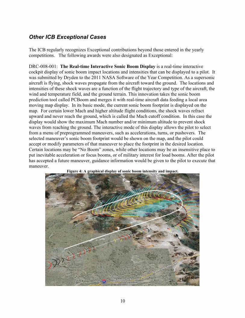
The ICB regularly recognizes Exceptional contributions beyond those entered in the yearly competitions. The following awards were also designated as Exceptional: DRC-008-001: The Real-time Interactive Sonic Boom Display is a real-time interactive cockpit display of sonic boom impact locations and intensities that can be displayed to a pilot. It was submitted by Dryden to the 2011 NASA Software of the Year Competition. As a supersonic aircraft is flying, shock waves propagate from the aircraft toward the ground. The locations and intensities of these shock waves are a function of the flight trajectory and type of the aircraft, the wind and temperature field, and the ground terrain. This innovation takes the sonic boom prediction tool called PCBoom and merges it with real-time aircraft data feeding a local area moving map display. In its basic mode, the current sonic boom footprint is displayed on the map. For certain lower Mach and higher altitude flight conditions, the shock waves refract upward and never reach the ground, which is called the Mach cutoff condition. In this case the display would show the maximum Mach number and/or minimum altitude to prevent shock waves from reaching the ground. The interactive mode of this display allows the pilot to select from a menu of preprogrammed maneuvers, such as accelerations, turns, or pushovers. The selected maneuver’s sonic boom footprint would be shown on the map, and the pilot could accept or modify parameters of that maneuver to place the footprint in the desired location. Certain locations may be “No Boom” zones, while other locations may be an insensitive place to put inevitable acceleration or focus booms, or of military interest for loud booms. After the pilot has accepted a future maneuver, guidance information would be given to the pilot to execute that maneuver.
Figure 4: A graphical display of sonic boom intensity and impact.
11
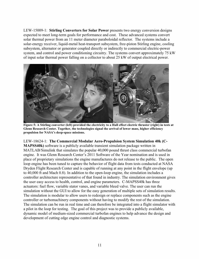
LEW-15009-1: Stirling Converters for Solar Power presents two energy conversion designs expected to meet long-term goals for performance and cost. These advanced systems convert solar thermal power from an 11 meter diameter paraboloidal reflector. The systems include a solar-energy receiver, liquid-metal heat-transport subsystem, free-piston Stirling engine, cooling subsystem, alternator or generator coupled directly or indirectly to commercial electric-power system, and control and power conditioning circuitry. The systems convert approximately 75 kW of input solar thermal power falling on a collector to about 25 kW of output electrical power.
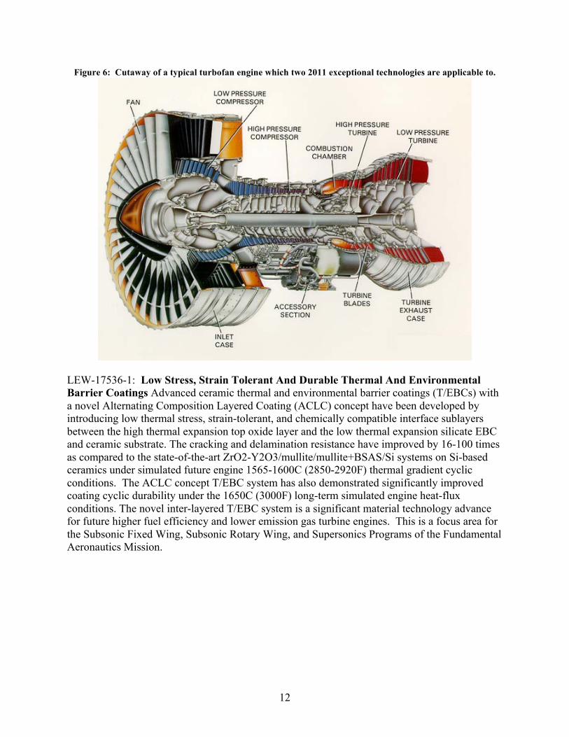
Figure 5: A Stirling converter (left) provided the electricity to a Hall effect electric thruster (right) in tests at Glenn Research Center. Together, the technologies signal the arrival of lower mass, higher efficiency propulsion for NASA’s deep-space missions. LEW-18624-1: The Commercial Modular Aero-Propulsion System Simulation 40k (C-MAPSS40k) software is a publicly available transient simulation package written in MATLAB/Simulink that simulates the popular 40,000 pound thrust class commercial turbofan engine. It was Glenn Research Center’s 2011 Software of the Year nomination and is used in place of proprietary simulations the engine manufactures do not release to the public. The open loop engine has been tuned to capture the behavior of flight data from tests conducted at NASA Dryden Flight Research Center and is capable of running at any point in the flight envelope (up to 40,000 ft and Mach 0.8). In addition to the open-loop engine, the simulation includes a controller architecture representative of that found in industry. The simulation environment gives the user easy access to health, control, and engine parameters. C-MAPSS40k has three actuators: fuel flow, variable stator vanes, and variable bleed valve. The user can run the simulation without the GUI to allow for the easy generation of multiple sets of simulation results. The simulation is modular to allow users to redesign or replace components such as the engine controller or turbomachinery components without having to modify the rest of the simulation. The simulation can be run in real time and can therefore be integrated into a flight simulator with a pilot in the loop for testing. The goal of this project was to provide a publicly available, dynamic model of medium-sized commercial turbofan engines to help advance the design and development of cutting edge engine control and diagnostic systems.
12
Figure 6: Cutaway of a typical turbofan engine which two 2011 exceptional technologies are applicable to.
LEW-17536-1: Low Stress, Strain Tolerant And Durable Thermal And Environmental Barrier Coatings Advanced ceramic thermal and environmental barrier coatings (T/EBCs) with a novel Alternating Composition Layered Coating (ACLC) concept have been developed by introducing low thermal stress, strain-tolerant, and chemically compatible interface sublayers between the high thermal expansion top oxide layer and the low thermal expansion silicate EBC and ceramic substrate. The cracking and delamination resistance have improved by 16-100 times as compared to the state-of-the-art ZrO2-Y2O3/mullite/mullite+BSAS/Si systems on Si-based ceramics under simulated future engine 1565-1600C (2850-2920F) thermal gradient cyclic conditions. The ACLC concept T/EBC system has also demonstrated significantly improved coating cyclic durability under the 1650C (3000F) long-term simulated engine heat-flux conditions. The novel inter-layered T/EBC system is a significant material technology advance for future higher fuel efficiency and lower emission gas turbine engines. This is a focus area for the Subsonic Fixed Wing, Subsonic Rotary Wing, and Supersonics Programs of the Fundamental Aeronautics Mission.
13
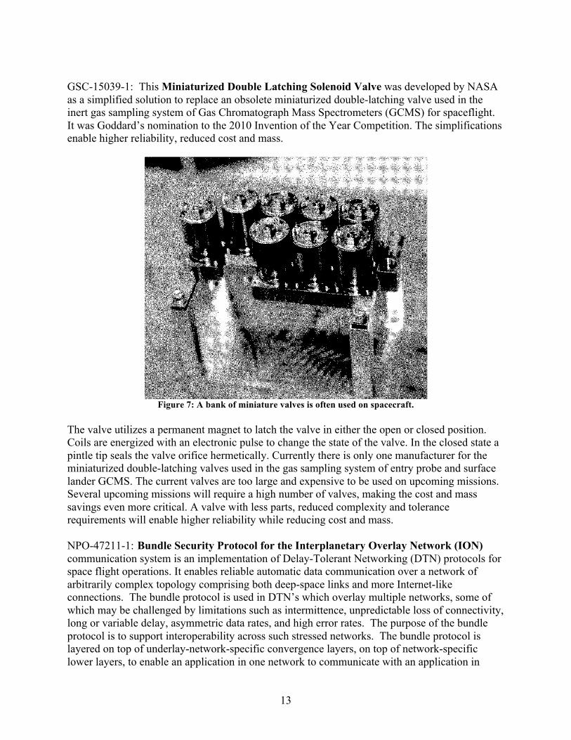
GSC-15039-1: This Miniaturized Double Latching Solenoid Valve was developed by NASA as a simplified solution to replace an obsolete miniaturized double-latching valve used in the inert gas sampling system of Gas Chromatograph Mass Spectrometers (GCMS) for spaceflight. It was Goddard’s nomination to the 2010 Invention of the Year Competition. The simplifications enable higher reliability, reduced cost and mass.
Figure 7: A bank of miniature valves is often used on spacecraft.
The valve utilizes a permanent magnet to latch the valve in either the open or closed position. Coils are energized with an electronic pulse to change the state of the valve. In the closed state a pintle tip seals the valve orifice hermetically. Currently there is only one manufacturer for the miniaturized double-latching valves used in the gas sampling system of entry probe and surface lander GCMS. The current valves are too large and expensive to be used on upcoming missions. Several upcoming missions will require a high number of valves, making the cost and mass savings even more critical. A valve with less parts, reduced complexity and tolerance requirements will enable higher reliability while reducing cost and mass. NPO-47211-1: Bundle Security Protocol for the Interplanetary Overlay Network (ION) communication system is an implementation of Delay-Tolerant Networking (DTN) protocols for space flight operations. It enables reliable automatic data communication over a network of arbitrarily complex topology comprising both deep-space links and more Internet-like connections. The bundle protocol is used in DTN’s which overlay multiple networks, some of which may be challenged by limitations such as intermittence, unpredictable loss of connectivity, long or variable delay, asymmetric data rates, and high error rates. The purpose of the bundle protocol is to support interoperability across such stressed networks. The bundle protocol is layered on top of underlay-network-specific convergence layers, on top of network-specific lower layers, to enable an application in one network to communicate with an application in
14
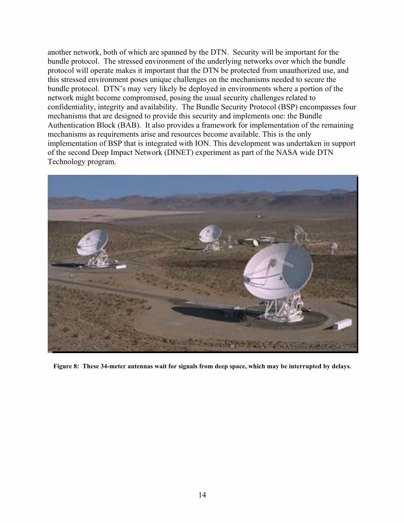
another network, both of which are spanned by the DTN. Security will be important for the bundle protocol. The stressed environment of the underlying networks over which the bundle protocol will operate makes it important that the DTN be protected from unauthorized use, and this stressed environment poses unique challenges on the mechanisms needed to secure the bundle protocol. DTN’s may very likely be deployed in environments where a portion of the network might become compromised, posing the usual security challenges related to confidentiality, integrity and availability. The Bundle Security Protocol (BSP) encompasses four mechanisms that are designed to provide this security and implements one: the Bundle Authentication Block (BAB). It also provides a framework for implementation of the remaining mechanisms as requirements arise and resources become available. This is the only implementation of BSP that is integrated with ION. This development was undertaken in support of the second Deep Impact Network (DINET) experiment as part of the NASA wide DTN Technology program.
Figure 8: These 34-meter antennas wait for signals from deep space, which may be interrupted by delays.
15
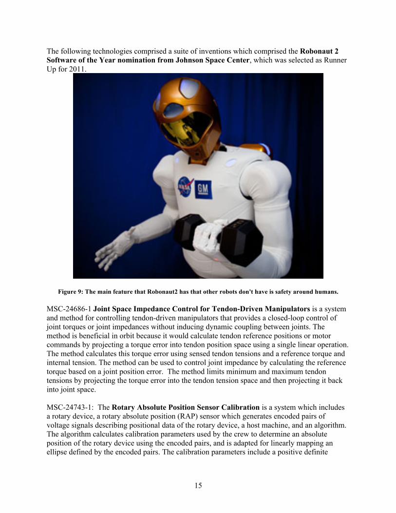
The following technologies comprised a suite of inventions which comprised the Robonaut 2 Software of the Year nomination from Johnson Space Center, which was selected as Runner Up for 2011.
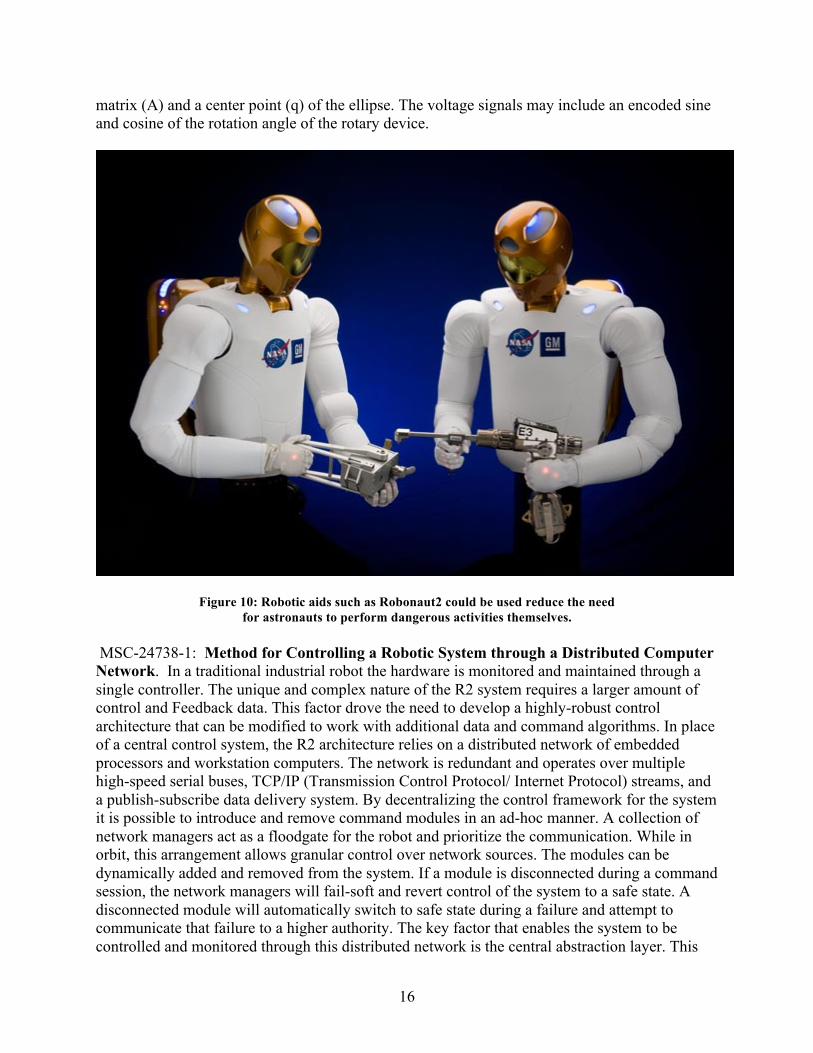
Figure 9: The main feature that Robonaut2 has that other robots don't have is safety around humans. MSC-24686-1 Joint Space Impedance Control for Tendon-Driven Manipulators is a system and method for controlling tendon-driven manipulators that provides a closed-loop control of joint torques or joint impedances without inducing dynamic coupling between joints. The method is beneficial in orbit because it would calculate tendon reference positions or motor commands by projecting a torque error into tendon position space using a single linear operation. The method calculates this torque error using sensed tendon tensions and a reference torque and internal tension. The method can be used to control joint impedance by calculating the reference torque based on a joint position error. The method limits minimum and maximum tendon tensions by projecting the torque error into the tendon tension space and then projecting it back into joint space. MSC-24743-1: The Rotary Absolute Position Sensor Calibration is a system which includes a rotary device, a rotary absolute position (RAP) sensor which generates encoded pairs of voltage signals describing positional data of the rotary device, a host machine, and an algorithm. The algorithm calculates calibration parameters used by the crew to determine an absolute position of the rotary device using the encoded pairs, and is adapted for linearly mapping an ellipse defined by the encoded pairs. The calibration parameters include a positive definite
16
matrix (A) and a center point (q) of the ellipse. The voltage signals may include an encoded sine and cosine of the rotation angle of the rotary device.
Figure 10: Robotic aids such as Robonaut2 could be used reduce the need for astronauts to perform dangerous activities themselves.
MSC-24738-1: Method for Controlling a Robotic System through a Distributed Computer Network. In a traditional industrial robot the hardware is monitored and maintained through a single controller. The unique and complex nature of the R2 system requires a larger amount of control and Feedback data. This factor drove the need to develop a highly-robust control architecture that can be modified to work with additional data and command algorithms. In place of a central control system, the R2 architecture relies on a distributed network of embedded processors and workstation computers. The network is redundant and operates over multiple high-speed serial buses, TCP/IP (Transmission Control Protocol/ Internet Protocol) streams, and a publish-subscribe data delivery system. By decentralizing the control framework for the system it is possible to introduce and remove command modules in an ad-hoc manner. A collection of network managers act as a floodgate for the robot and prioritize the communication. While in orbit, this arrangement allows granular control over network sources. The modules can be dynamically added and removed from the system. If a module is disconnected during a command session, the network managers will fail-soft and revert control of the system to a safe state. A disconnected module will automatically switch to safe state during a failure and attempt to communicate that failure to a higher authority. The key factor that enables the system to be controlled and monitored through this distributed network is the central abstraction layer. This
17
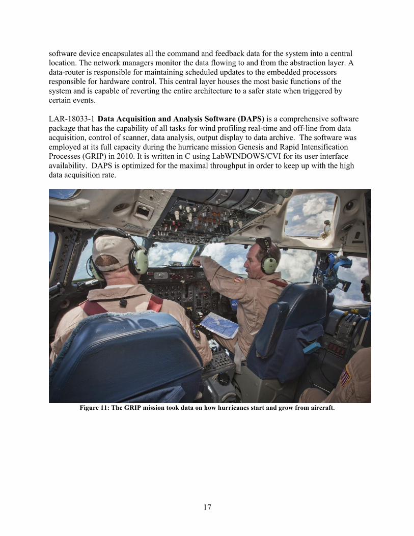
software device encapsulates all the command and feedback data for the system into a central location. The network managers monitor the data flowing to and from the abstraction layer. A data-router is responsible for maintaining scheduled updates to the embedded processors responsible for hardware control. This central layer houses the most basic functions of the system and is capable of reverting the entire architecture to a safer state when triggered by certain events. LAR-18033-1 Data Acquisition and Analysis Software (DAPS) is a comprehensive software package that has the capability of all tasks for wind profiling real-time and off-line from data acquisition, control of scanner, data analysis, output display to data archive. The software was employed at its full capacity during the hurricane mission Genesis and Rapid Intensification Processes (GRIP) in 2010. It is written in C using LabWINDOWS/CVI for its user interface availability. DAPS is optimized for the maximal throughput in order to keep up with the high data acquisition rate.
Figure 11: The GRIP mission took data on how hurricanes start and grow from aircraft.
18
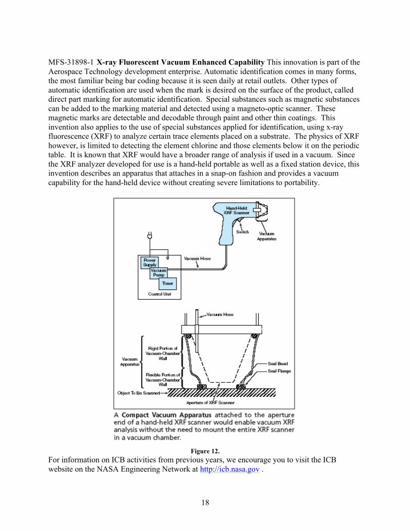
MFS-31898-1 X-ray Fluorescent Vacuum Enhanced Capability This innovation is part of the Aerospace Technology development enterprise. Automatic identification comes in many forms, the most familiar being bar coding because it is seen daily at retail outlets. Other types of automatic identification are used when the mark is desired on the surface of the product, called direct part marking for automatic identification. Special substances such as magnetic substances can be added to the marking material and detected using a magneto-optic scanner. These magnetic marks are detectable and decodable through paint and other thin coatings. This invention also applies to the use of special substances applied for identification, using x-ray fluorescence (XRF) to analyze certain trace elements placed on a substrate. The physics of XRF however, is limited to detecting the element chlorine and those elements below it on the periodic table. It is known that XRF would have a broader range of analysis if used in a vacuum. Since the XRF analyzer developed for use is a hand-held portable as well as a fixed station device, this invention describes an apparatus that attaches in a snap-on fashion and provides a vacuum capability for the hand-held device without creating severe limitations to portability.
Figure 12.
For information on ICB activities from previous years, we encourage you to visit the ICB website on the NASA Engineering Network at http://icb.nasa.gov .
19
The 2011 Board and Staff: Recognizing the Inventors The Inventions and Contributions Board for this year was made up of the following membership: Dr. Michael G. Ryschkewitsch, Chair and NASA Chief Engineer Dr. Donald C. Braun, GRC, Vice Chair Ms. Helen M. Galus, Counsel to the Board, HQ Dr. G. Dickey Arndt, JSC Dr. Biliyar (Bil) N. Bhat, MSFC Mr. John O. Bristow, GSFC Ms. Sandra A. Cauffman, GSFC Mr. Donald O. Frazier, MSFC Dr. Minoru M. Freund, ARC John E. James, JSC Dr. Dochan Kwak, ARC Roy W. Malone, MSFC David C. McComas, GSFC Mr. Richard McGinnis, HQ Dr. Maryann Meador, GRC Dr. Ruth H. Pater, LaRC Dr. Christa D. Peters-Lidard, GSFC Dr. Jacqueline (Jackie) W. Quinn, KSC Ms. Pamela R. Rinsland, LaRC Robert T. Savely, JSC Dr. Leland (Lee) S. Stone, ARC Ms. Caroline K. Wang, MSFC Dr. Robert (Bob) C. Youngquist, KSC Board Staff: Mr. Anthony (Tony) J. Maturo, Staff Director Mr. Jesse C. Midgett, Chief Technologist Ms. Iona Butler, Records Manager Ms. Angela F. Greene, Budget Assistant
20
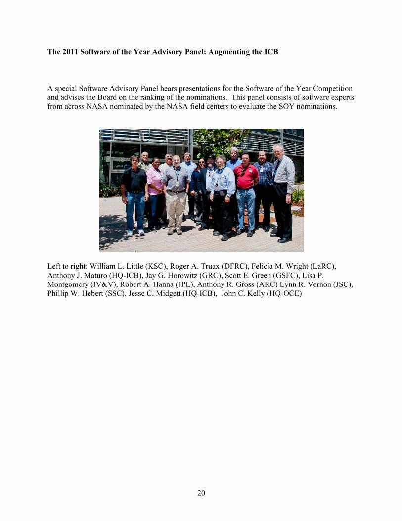
The 2011 Software of the Year Advisory Panel: Augmenting the ICB A special Software Advisory Panel hears presentations for the Software of the Year Competition and advises the Board on the ranking of the nominations. This panel consists of software experts from across NASA nominated by the NASA field centers to evaluate the SOY nominations.
Left to right: William L. Little (KSC), Roger A. Truax (DFRC), Felicia M. Wright (LaRC), Anthony J. Maturo (HQ-ICB), Jay G. Horowitz (GRC), Scott E. Green (GSFC), Lisa P. Montgomery (IV&V), Robert A. Hanna (JPL), Anthony R. Gross (ARC) Lynn R. Vernon (JSC), Phillip W. Hebert (SSC), Jesse C. Midgett (HQ-ICB), John C. Kelly (HQ-OCE)
21
The 2011 Awards Liaison Officers: Priming the ICB Process The Field Centers also support the ICB by providing Awards Liaison Officers (ALO) at each Field Center, Patent Counsels and Attorneys, and technology transfer and software release authority personnel. The ALO’s diligently submit their Centers’ qualified inventors for ICB consideration throughout the year. Please refer to the contact information below for information on the ICB Award program at a specific NASA Center, as all ICB award submissions must go through a Center ALO. CENTER AWARDS LIAISON OFFICERS: Ms. Robin Orans, Ames Research Center M.S. 202A-3 Moffett Field, CA 94035-1000 650-604-5875 [email protected] Ms. Yvonne Gibbs, Dryden Flight Research Center P.O. Box 273, M.S. 2506 Edwards CA 93523-0273 (661) 276-3720 [email protected] Ms. Laurie Stauber, Glenn Research Center Bldg. 4, Rm. 106, Mail Stop 4-2 21000 Brookpark Road Cleveland, OH 44135 216-433-2820 [email protected] Ms. Dale Clarke Goddard Space Flight Center, Mail Code 504 Greenbelt, MD 20771 301-286-2691 [email protected] Dr. Christopher H. Jaggers Jet Propulsion Laboratory M/S: 202-233 4800 Oak Grove Drive Pasadena, CA 91109 818-393-4904 [email protected]
22
Ms. Arlene Andrews 2101 NASA Parkway Building 45, Room 448I Houston, TX 77058 281-483-8341 [email protected] Ms. Carol A. Dunn Kennedy Space Center Mail Stop: KT-A2 Kennedy Space Center, FL 32899 321-867-6381 [email protected] Ms. Susan Cooper Langley Research Center Building 1212, Room 133 Mail Stop 218 Hampton, VA 23681-2199 757-864-2989 [email protected] Ms. Carolyn E. McMillan Marshall Space Flight Center Building 4610, Room 5034 Mail Stop ZP30 Huntsville, AL 35812 256-544-9151 [email protected] Ms. Liteshia B. Dennis NASA Headquarters 300 E St. SW, Suite 4B33 Washington, DC 20546-0001 202-358-4778 [email protected] Mr. James (Ray) Bryant Stennis Space Center HA30/Technology Development and Transfer Office Building 1100, Room 2017A Stennis Space Center, MS 39529 228-688-3964 [email protected]
23
2011 ICB Annual Report Acronym List ACLC Alternating Composition Layered Coating AEGIS Autonomous Exploration for Gathering Increased Science System ARC Ames Research Center ATM Air Traffic Management BAB Bundle Authentication Block BSP Bundle Security Protocol C Celsius degrees ChemCam Chemistry and Camera C-MAPSS40k Commercial Modular Aero-Propulsion System Simulation for 40,000 pounds thrust engines DINET Deep Impact Network DFRC or DRC Dryden Flight Research Center DTN Delay-Tolerant Networking EDT Eastern Daylight Time F Fahrenheit FACET Future ATM Concepts Evaluation Tool GCMS Gas Chromatograph Mass Spectrometers GRC Glenn Research Center GRIP Genesis and Rapid Intensification Processes GSC or GSFC Goddard Space Flight Center GUI Graphical User Interface HQ NASA Headquarters ICB Inventions and Contributions Board ION Interplanetary Overlay Network IOY NASA Invention of the Year IPOEF Intellectual Property Owners Educational Foundation IPOPP International Polar Orbiter Processing Package JPL Jet Propulsion Laboratory JSC Johnson Space Center KSC Kennedy Space Center kW kilowatt= 1000 Watts of electrical power LaRC/LAR Langley Research Center LEW Glenn Research Center (formerly Lewis Research Center) MER Mars Exploration Rover MSC Johnson Space Center (formerly Manned Spaceflight Center) MSFC or MFS Marshall Space Flight Center MSL Mars Science Laboratory MSR Mars Sample Return NACA National Advisory Committee on Aeronautics NASA National Aeronautics and Space Administration NEN NASA Engineering Network NPO Jet Propulsion Laboratory (formerly NASA Pasadena Office)
24
OCE Office of the Chief Engineer OCIO Office of the Chief Information Officer OCT Office of Chief Technologist OGC Office of the General Counsel OSMA Office of Safety and Mission Assurance RAP Rotary Absolute Position sensor R2 Robonaut2 PCBoom Personal Computer Sonic boom prediction software SOY NASA Software of the Year SSC Stennis Space Center STS Space Transportation System Mini-TES Miniature Thermal Emission Spectrometer TCP/IP Transmission Control Protocol/ Internet Protocol T/EBCs Thermal and Environmental Barrier Coatings XRF x-ray fluorescence www.nasa.gov the World Wide Web location for the NASA Government operated website
25
Credits Compiled by Jesse C. Midgett Inventions and Contributions Board Chief Technologist, Langley Research Center For more information, visit the ICB Web site at http://icb.nasa.gov.