Embed Size (px)
Citation preview
Brief Manual of EK-100SL
Ver. 1.3
ELT SENSOR
INDEX
I. Overview
II. Introduction
III. ELT SENSOR Development System
▷ EK-100S Evaluation Board
▷ Hardware Installation
IV. ELTWSD_EK100 emulation Program
▷ Monitoring or Upgrade Sequence
1. S-100, S110, S300E with ATmega CPU
2. S-200, S300, D300 with ADuC848 CPU
V. Ordering Guide for EK-100
▷ PRODUCT Code
1. EK-100S
2. EK-100T
1/12
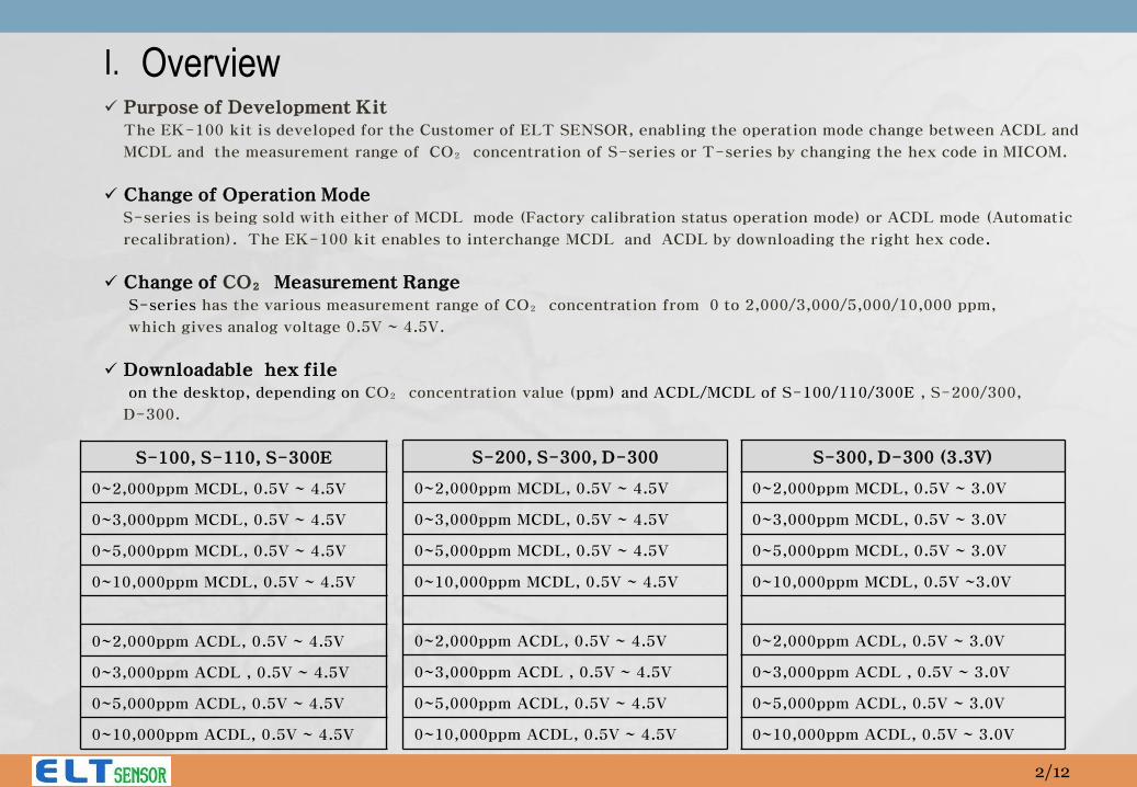
Overview Purpose of Development Kit
The EK-100 kit is developed for the Customer of ELT SENSOR, enabling the operation mode change between ACDL and
MCDL and the measurement range of CO₂ concentration of S-series or T-series by changing the hex code in MICOM.
Change of Operation Mode S-series is being sold with either of MCDL mode (Factory calibration status operation mode) or ACDL mode (Automatic
recalibration). The EK-100 kit enables to interchange MCDL and ACDL by downloading the right hex code.
Change of CO₂ Measurement Range S-series has the various measurement range of CO₂ concentration from 0 to 2,000/3,000/5,000/10,000 ppm,
which gives analog voltage 0.5V ~ 4.5V.
Downloadable hex file on the desktop, depending on CO₂ concentration value (ppm) and ACDL/MCDL of S-100/110/300E , S-200/300,
D-300.
S-100, S-110, S-300E
0~2,000ppm MCDL, 0.5V ~ 4.5V
0~3,000ppm MCDL, 0.5V ~ 4.5V
0~5,000ppm MCDL, 0.5V ~ 4.5V
0~10,000ppm MCDL, 0.5V ~ 4.5V
0~2,000ppm ACDL, 0.5V ~ 4.5V
0~3,000ppm ACDL , 0.5V ~ 4.5V
0~5,000ppm ACDL, 0.5V ~ 4.5V
0~10,000ppm ACDL, 0.5V ~ 4.5V
S-200, S-300, D-300
0~2,000ppm MCDL, 0.5V ~ 4.5V
0~3,000ppm MCDL, 0.5V ~ 4.5V
0~5,000ppm MCDL, 0.5V ~ 4.5V
0~10,000ppm MCDL, 0.5V ~ 4.5V
0~2,000ppm ACDL, 0.5V ~ 4.5V
0~3,000ppm ACDL , 0.5V ~ 4.5V
0~5,000ppm ACDL, 0.5V ~ 4.5V
0~10,000ppm ACDL, 0.5V ~ 4.5V
I.
2/12
S-300, D-300 (3.3V)
0~2,000ppm MCDL, 0.5V ~ 3.0V
0~3,000ppm MCDL, 0.5V ~ 3.0V
0~5,000ppm MCDL, 0.5V ~ 3.0V
0~10,000ppm MCDL, 0.5V ~3.0V
0~2,000ppm ACDL, 0.5V ~ 3.0V
0~3,000ppm ACDL , 0.5V ~ 3.0V
0~5,000ppm ACDL, 0.5V ~ 3.0V
0~10,000ppm ACDL, 0.5V ~ 3.0V
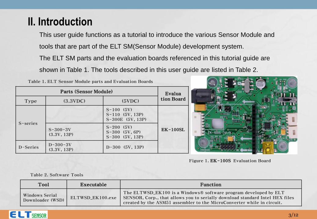
II. Introduction This user guide functions as a tutorial to introduce the various Sensor Module and
tools that are part of the ELT SM(Sensor Module) development system.
The ELT SM parts and the evaluation boards referenced in this tutorial guide are
shown in Table 1. The tools described in this user guide are listed in Table 2.
Parts (Sensor Module) Evalua tion Board Type (3.3VDC) (5VDC)
S-series
S-100 (5V) S-110 (5V, 13P) S-300E (5V, 13P)
EK-100SL S-300-3V (3.3V, 13P)
S-200 (5V) S-300 (5V, 6P) S-300 (5V, 13P)
D-Series D-300-3V (3.3V, 13P)
D-300 (5V, 13P)
Table 1. ELT Sensor Module parts and Evaluation Boards
Table 2. Software Tools
Tool Executable Function
Windows Serial Downloader (WSD)
ELTWSD_EK100.exe The ELTWSD_EK100 is a Windows® software program developed by ELT SENSOR, Corp., that allows you to serially download standard Intel HEX files created by the ASM51 assembler to the MicroConverter while in circuit.
Figure 1. EK-100S Evaluation Board
3/12
AC/DC POWER Adaptor (12VDC / over 0.5A)
A1
A2
A
B
C
C1
PC
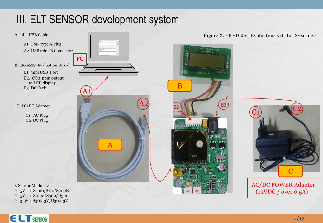
III. ELT SENSOR development system A. mini USB Cable
A1. USB type A Plug
A2. USB mini-B Connector
B. EK-100S Evaluation Board
B1. mini USB Port
B2. CO2 ppm output to LCD display B3. DC Jack
< Sensor Module > 5V : S-100/S110/S300E 5V : S-200/S300/D300 3.3V : S300-3V/D300-3V
C. AC/DC Adapter
C1. AC Plug C2. DC Plug
C2
Figure 2. EK-100SL Evaluation Kit (for S-series)
4/12
J5
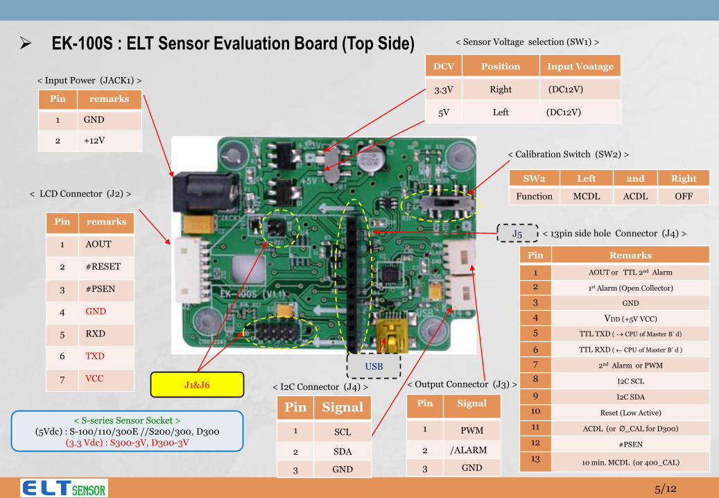
< S-series Sensor Socket > (5Vdc) : S-100/110/300E //S200/300, D300
(3.3 Vdc) : S300-3V, D300-3V
J1&J6
DCV Position Input Voatage
3.3V Right (DC12V)
5V Left (DC12V)
EK-100S : ELT Sensor Evaluation Board (Top Side)
Pin remarks
1 GND
2 +12V
< Input Power (JACK1) >
< Sensor Voltage selection (SW1) >
Pin remarks
1 AOUT
2 #RESET
3 #PSEN
4 GND
5 RXD
6 TXD
7 VCC
< LCD Connector (J2) >
Pin Signal
1 PWM
2 /ALARM
3 GND
< Output Connector (J3) >
SW2 Left 2nd Right
Function MCDL ACDL OFF
< Calibration Switch (SW2) >
Pin Signal
1 SCL
2 SDA
3 GND
< I2C Connector (J4) >
USB
5/12
< 13pin side hole Connector (J4) >
Pin Remarks
1 AOUT or TTL 2nd Alarm
2 1st Alarm (Open Collector)
3 GND
4 VDD (+5V VCC)
5 TTL TXD ( CPU of Master B’ d)
6 TTL RXD ( CPU of Master B’ d )
7 2nd Alarm or PWM
8 I2C SCL
9 I2C SDA
10 Reset (Low Active)
11 ACDL (or Ø_CAL for D300)
12 #PSEN
13 10 min. MCDL (or 400_CAL)
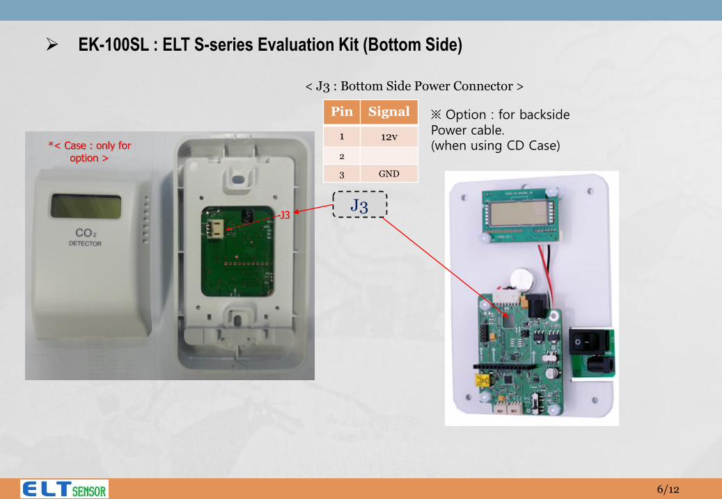
EK-100SL : ELT S-series Evaluation Kit (Bottom Side)
J3
Pin Signal
1 12v
2
3 GND
※ Option : for backside Power cable. (when using CD Case)
< J3 : Bottom Side Power Connector >
6/12
A1 A2
C1
C2
B1
B3
A (USB)
C
B PC
12V AC/DC POWER Adaptor
EK-100SL
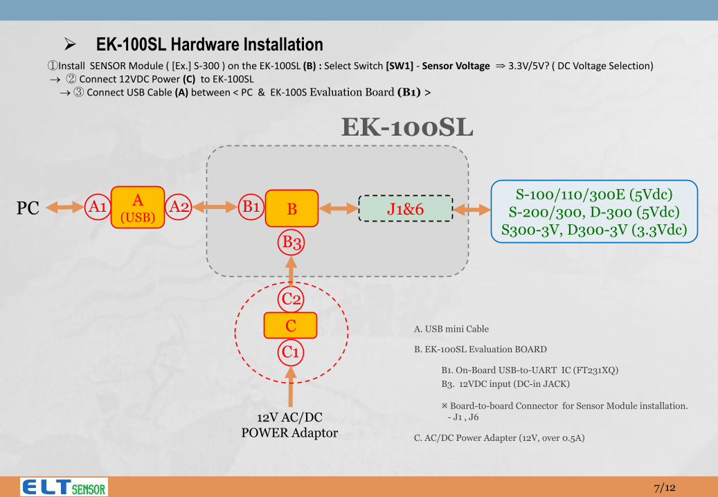
A. USB mini Cable
B. EK-100SL Evaluation BOARD
B1. On-Board USB-to-UART IC (FT231XQ)
B3. 12VDC input (DC-in JACK) Board-to-board Connector for Sensor Module installation.
- J1 , J6
C. AC/DC Power Adapter (12V, over 0.5A)
S-100/110/300E (5Vdc) S-200/300, D-300 (5Vdc)
S300-3V, D300-3V (3.3Vdc)
J1&6
EK-100SL Hardware Installation ①Install SENSOR Module ( [Ex.] S-300 ) on the EK-100SL (B) : Select Switch [SW1] - Sensor Voltage ⇒ 3.3V/5V? ( DC Voltage Selection) ② Connect 12VDC Power (C) to EK-100SL ③ Connect USB Cable (A) between < PC & EK-100S Evaluation Board (B1) >
7/12
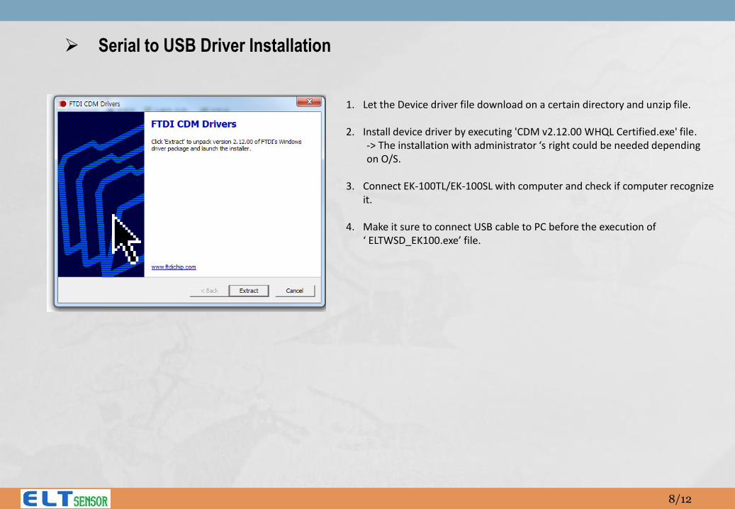
1. Let the Device driver file download on a certain directory and unzip file.
2. Install device driver by executing 'CDM v2.12.00 WHQL Certified.exe' file. -> The installation with administrator ‘s right could be needed depending on O/S.
3. Connect EK-100TL/EK-100SL with computer and check if computer recognize
it.
4. Make it sure to connect USB cable to PC before the execution of ‘ ELTWSD_EK100.exe’ file.
Serial to USB Driver Installation
8/12
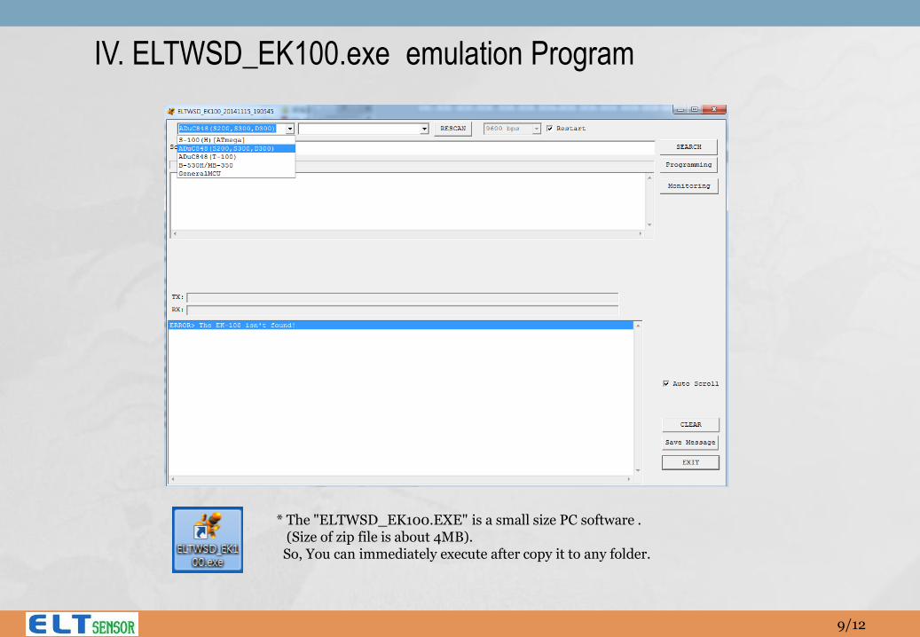
IV. ELTWSD_EK100.exe emulation Program
* The "ELTWSD_EK100.EXE" is a small size PC software . (Size of zip file is about 4MB). So, You can immediately execute after copy it to any folder.
9/12
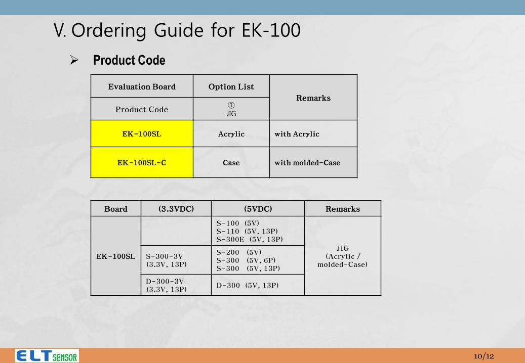
V. Ordering Guide for EK-100
Product Code
Board (3.3VDC) (5VDC) Remarks
EK-100SL
S-100 (5V) S-110 (5V, 13P) S-300E (5V, 13P)
JIG (Acrylic /
molded-Case) S-300-3V (3.3V, 13P)
S-200 (5V) S-300 (5V, 6P) S-300 (5V, 13P)
D-300-3V (3.3V, 13P)
D-300 (5V, 13P)
Evaluation Board Option List
Remarks
Product Code ① JIG
EK-100SL Acrylic with Acrylic
EK-100SL-C Case with molded-Case
10/12
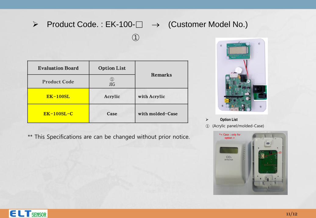
Product Code. : EK-100-□ (Customer Model No.)
①
Evaluation Board Option List
Remarks
Product Code ① JIG
EK-100SL Acrylic with Acrylic
EK-100SL-C Case with molded-Case
Option List
① (Acrylic panel/molded-Case)
** This Specifications are can be changed without prior notice.
11/12