Embed Size (px)
Citation preview

Brief ADSL2 ReviewBrief ADSL2 Review
Ian C. Wong, Daifeng Wang, andProf. Brian L. Evans
Dept. of Electrical and Comp. Eng.The University of Texas at Austin
http://signal.ece.utexas.edu
http://www.ece.utexas.edu/~bevans/projects/adsl
2
11ADSL2 and ADSL2+ - the new standardsADSL2 and ADSL2+ - the new standards
• ADSL2 (G.992.3 or G.dmt.bis, and G.992.4 or G.lite.bis)– Completed in July 2002
– Minimum of 8 Mbps downstream and 800 kbps upstream
– Improvements on:
• Data rate vs. reach performance
• Loop diagnostics
• Deployment from remote cabinets
• Spectrum and power control
• Robustness against loop impairments
• Operations and Maintenance
• ADSL2+ (G.992.5)– Completed in January 2003
– Doubles the bandwidth used for downstream data (~20Mbps at 5000 ft)
1Figures and text are extensively referenced from [ADSL2] [ADSL2white]
3
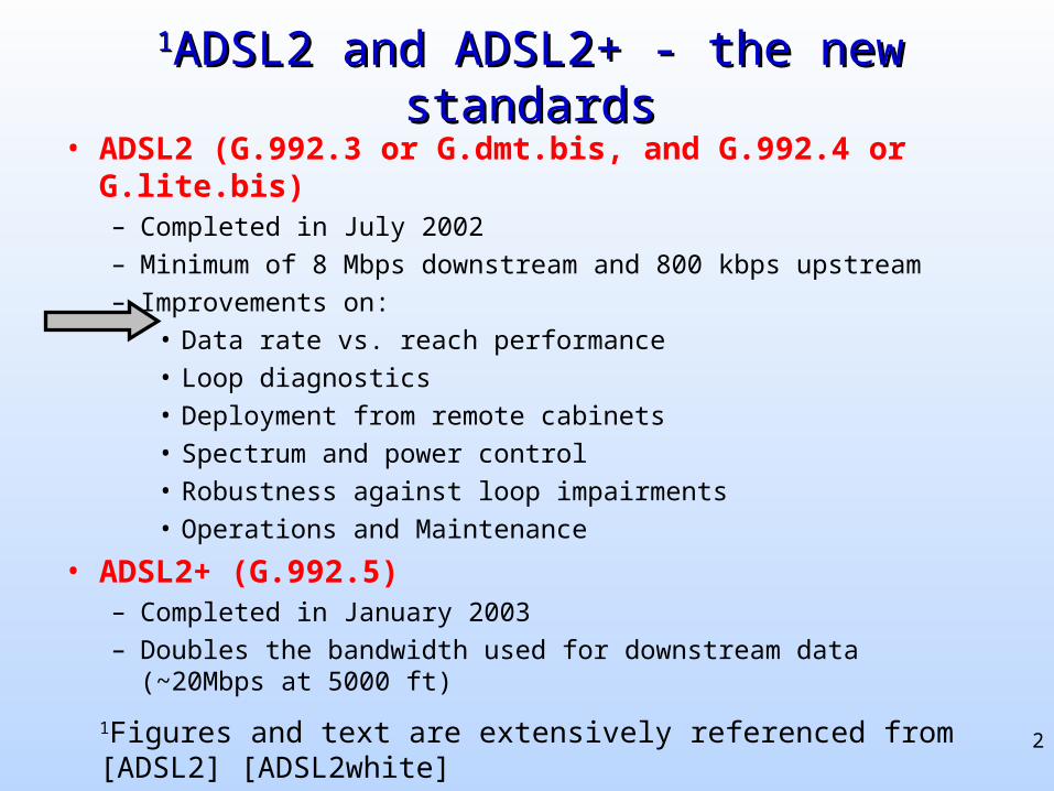
ATU-Functional ModelATU-Functional Model
4
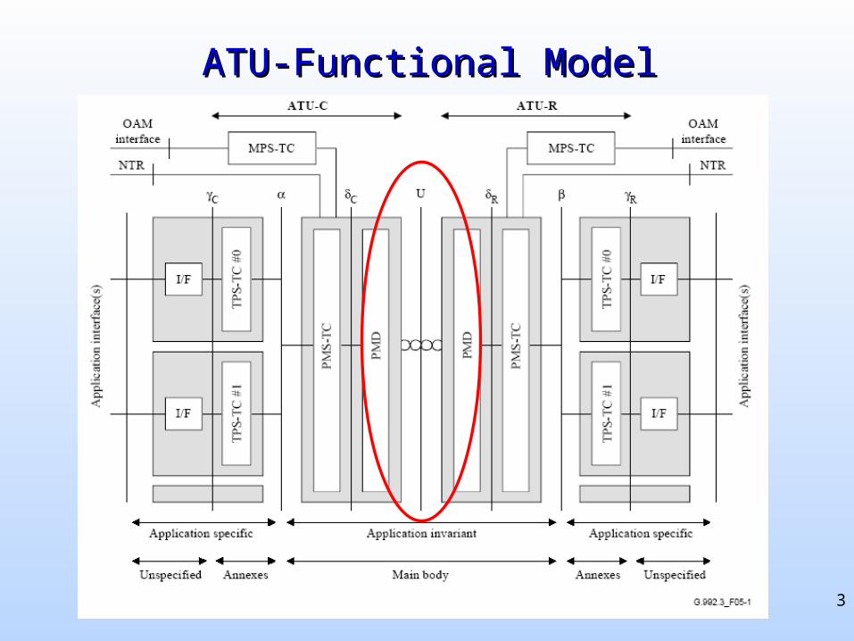
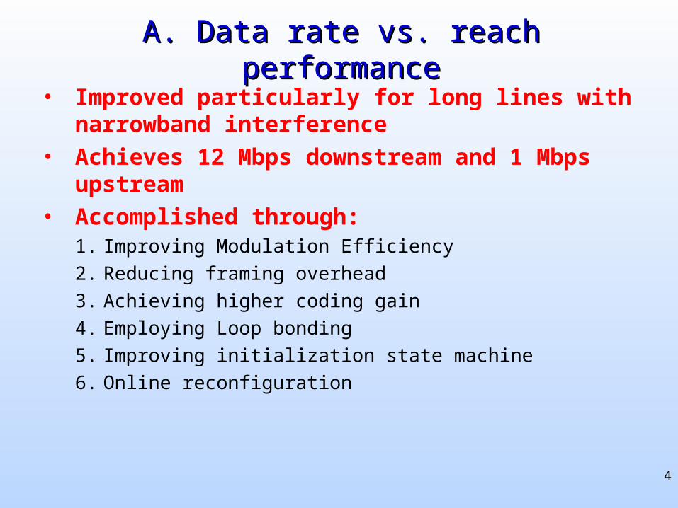
A. Data rate vs. reach performanceA. Data rate vs. reach performance
• Improved particularly for long lines with narrowband interference
• Achieves 12 Mbps downstream and 1 Mbps upstream
• Accomplished through:1. Improving Modulation Efficiency
2. Reducing framing overhead
3. Achieving higher coding gain
4. Employing Loop bonding
5. Improving initialization state machine
6. Online reconfiguration
5
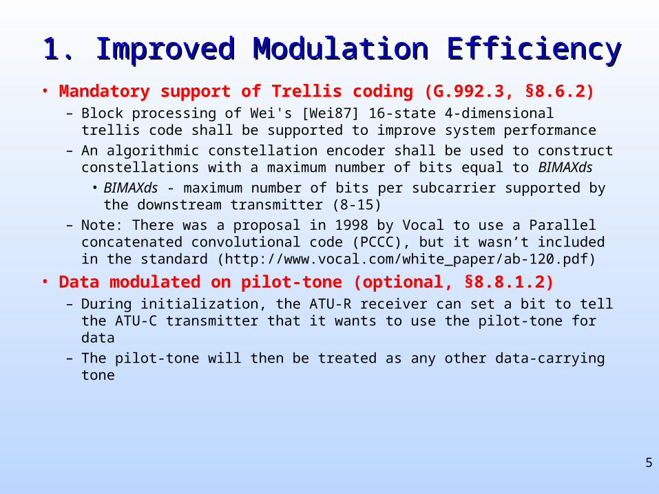
1. Improved Modulation Efficiency1. Improved Modulation Efficiency
• Mandatory support of Trellis coding (G.992.3, §8.6.2)– Block processing of Wei's [Wei87] 16-state 4-dimensional trellis code
shall be supported to improve system performance
– An algorithmic constellation encoder shall be used to construct constellations with a maximum number of bits equal to BIMAXds
• BIMAXds - maximum number of bits per subcarrier supported by the downstream transmitter (8-15)
– Note: There was a proposal in 1998 by Vocal to use a Parallel concatenated convolutional code (PCCC), but it wasn’t included in the standard (http://www.vocal.com/white_paper/ab-120.pdf)
• Data modulated on pilot-tone (optional, §8.8.1.2)– During initialization, the ATU-R receiver can set a bit to tell the ATU-
C transmitter that it wants to use the pilot-tone for data
– The pilot-tone will then be treated as any other data-carrying tone
6
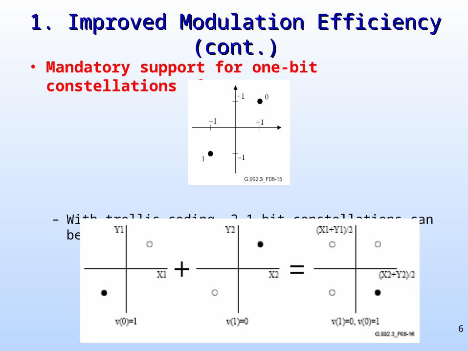
1. Improved Modulation Efficiency (cont.)1. Improved Modulation Efficiency (cont.)
• Mandatory support for one-bit constellations (§8.6.3.2)
– With trellis coding, 2 1-bit constellations can be combined:
7
2. Reduced framing overhead2. Reduced framing overhead
• Programmable number of overhead bits (§7.6)– Unlike ADSL where overhead bits are fixed and consume 32 kbps of
actual payload data
– In ADSL2, it is programmable between 4-32 kbps
– In long lines where data rate is low, e.g. 128 kbps,
• ADSL: 32/128 = 25% is overhead
• ADSL2: as low as 4/128 = 3.125% is overhead
8
3. Achieved higher coding gain3. Achieved higher coding gain
• On long lines where data rates are low, higher coding gain from the Reed-Solomon code can be achieved
• Flexible framing allows RS code to have (§7.7.1.4)• 0, 2, 4, 6, 8, 10, 12, 14, or 16 redundancy octets
• 0 redundancy implies no coding at all (for very good channels)
• 16 would achieve the highest coding gain at the expense of higher overhead (for very poor channels)
9
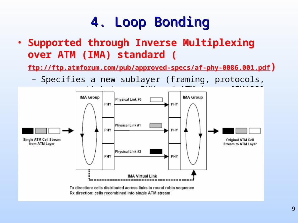
4. Loop Bonding4. Loop Bonding
• Supported through Inverse Multiplexing over ATM (IMA) standard (ftp://ftp.atmforum.com/pub/approved-specs/af-phy-0086.001.pdf)– Specifies a new sublayer (framing, protocols, management) between
PHY and ATM layer [IMA99]
10
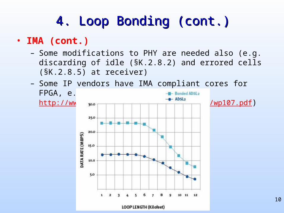
4. Loop Bonding (cont.)4. Loop Bonding (cont.)
• IMA (cont.)– Some modifications to PHY are needed also (e.g. discarding of idle
(§K.2.8.2) and errored cells (§K.2.8.5) at receiver)
– Some IP vendors have IMA compliant cores for FPGA, e.g. Xilinx (http://www.xilinx.com/bvdocs/whitepapers/wp107.pdf)
11
5. Improved initialization state machine5. Improved initialization state machine
1. Power cutback
2. Spectral Shaping
3. Receiver-determined pilot tones
12
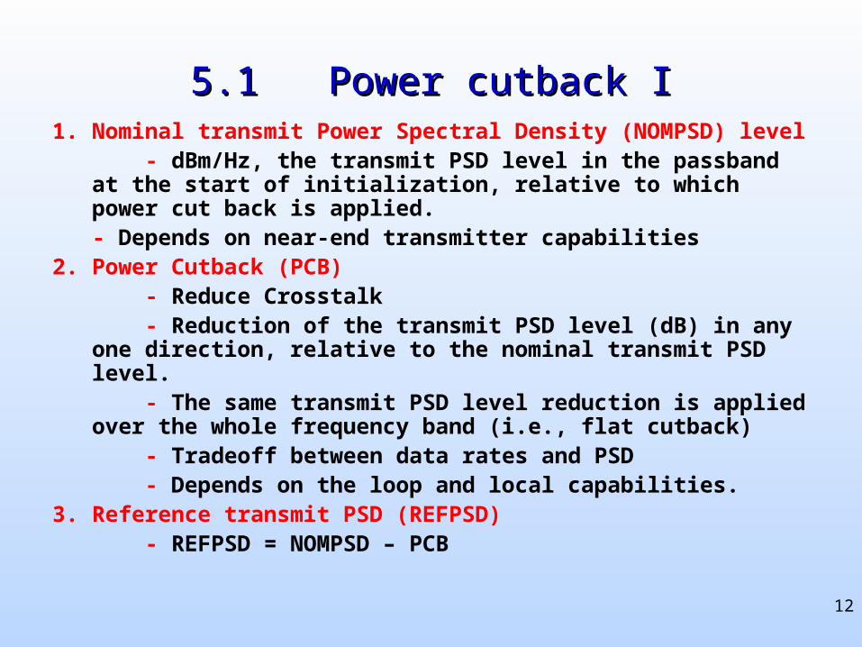
5.1 Power cutback I5.1 Power cutback I1. Nominal transmit Power Spectral Density (NOMPSD) level - dBm/Hz, the transmit PSD level in the passband at the start of
initialization, relative to which power cut back is applied.- Depends on near-end transmitter capabilities
2. Power Cutback (PCB) - Reduce Crosstalk - Reduction of the transmit PSD level (dB) in any one direction,
relative to the nominal transmit PSD level. - The same transmit PSD level reduction is applied over the whole
frequency band (i.e., flat cutback) - Tradeoff between data rates and PSD - Depends on the loop and local capabilities.3. Reference transmit PSD (REFPSD) - REFPSD = NOMPSD – PCB
13
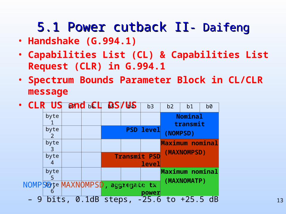
5.1 Power cutback II5.1 Power cutback II- Daifeng- Daifeng• Handshake (G.994.1)
• Capabilities List (CL) & Capabilities List Request (CLR) in G.994.1
• Spectrum Bounds Parameter Block in CL/CLR message
• CLR US and CL DS/US b7 b6 b5 b4 b3 b2 b1 b0
byte 1 Nominal transmit
(NOMPSD)byte 2 PSD levelbyte 3 Maximum nominal
(MAXNOMPSD)byte 4 Transmit PSD levelbyte 5 Maximum nominal
(MAXNOMATP)byte 6 aggregate tx power
NOMPSD, MAXNOMPSD, MAXNOMATP
– 9 bits, 0.1dB steps, -25.6 to +25.5 dB
14
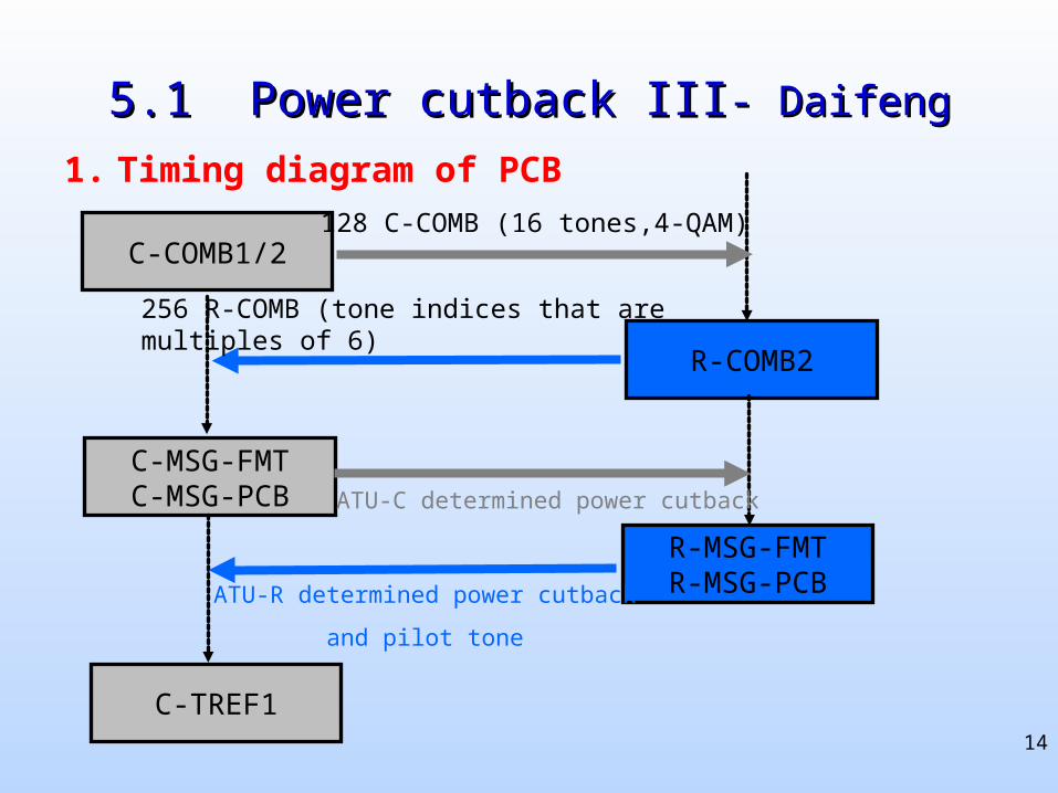
5.1 Power cutback III5.1 Power cutback III- Daifeng- Daifeng
1. Timing diagram of PCB
C-COMB1/2
C-MSG-FMTC-MSG-PCB
R-MSG-FMTR-MSG-PCB
R-COMB2
ATU-C determined power cutback
ATU-R determined power cutback
and pilot tone
C-TREF1
128 C-COMB (16 tones,4-QAM)
256 R-COMB (tone indices that are multiples of 6)
15
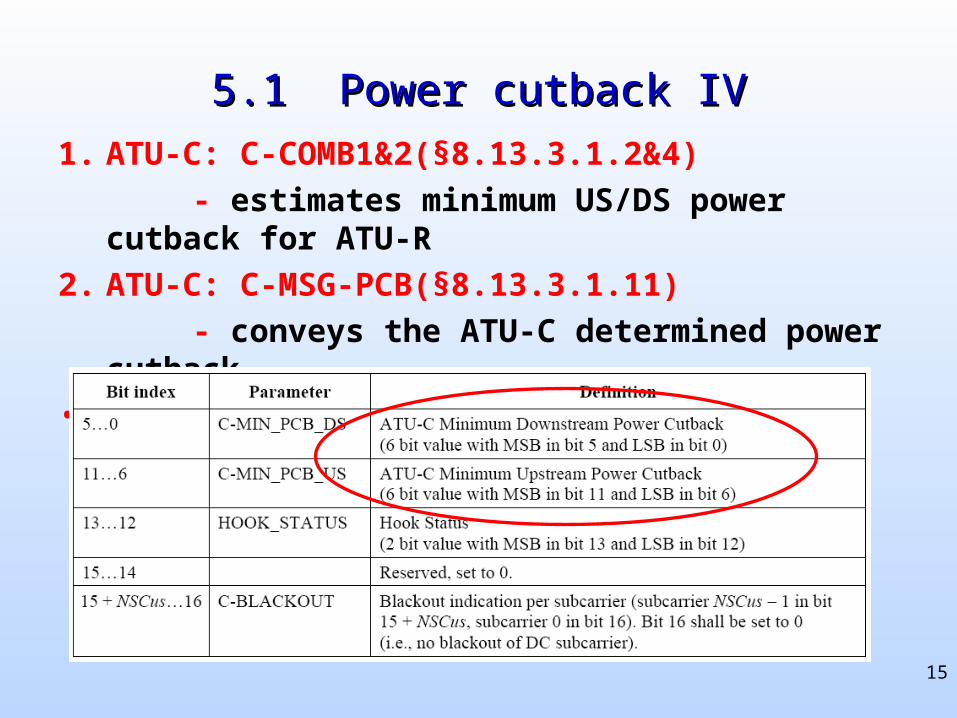
5.1 Power cutback IV5.1 Power cutback IV
1. ATU-C: C-COMB1&2(§8.13.3.1.2&4)
- estimates minimum US/DS power cutback for ATU-R
2. ATU-C: C-MSG-PCB(§8.13.3.1.11)
- conveys the ATU-C determined power cutback
• Definition for C-MSG-PCB
16
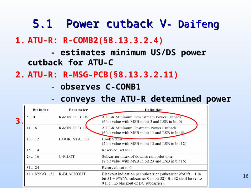
5.1 Power cutback V5.1 Power cutback V- Daifeng- Daifeng
1. ATU-R: R-COMB2(§8.13.3.2.4)
- estimates minimum US/DS power cutback for ATU-C
2. ATU-R: R-MSG-PCB(§8.13.3.2.11)
- observes C-COMB1
- conveys the ATU-R determined power cutback
3. Definition for R-MSG-PCB
17
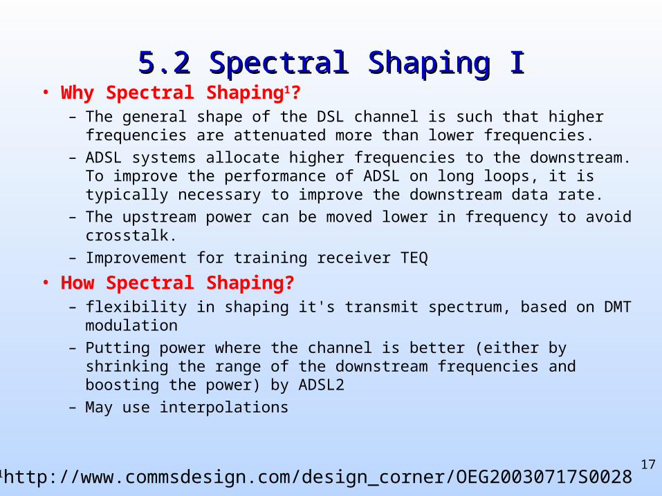
5.2 Spectral Shaping I5.2 Spectral Shaping I• Why Spectral Shaping1?
– The general shape of the DSL channel is such that higher frequencies are attenuated more than lower frequencies.
– ADSL systems allocate higher frequencies to the downstream. To improve the performance of ADSL on long loops, it is typically necessary to improve the downstream data rate.
– The upstream power can be moved lower in frequency to avoid crosstalk.
– Improvement for training receiver TEQ
• How Spectral Shaping?– flexibility in shaping it's transmit spectrum, based on DMT modulation
– Putting power where the channel is better (either by shrinking the range of the downstream frequencies and boosting the power) by ADSL2
– May use interpolations
1http://www.commsdesign.com/design_corner/OEG20030717S0028
18
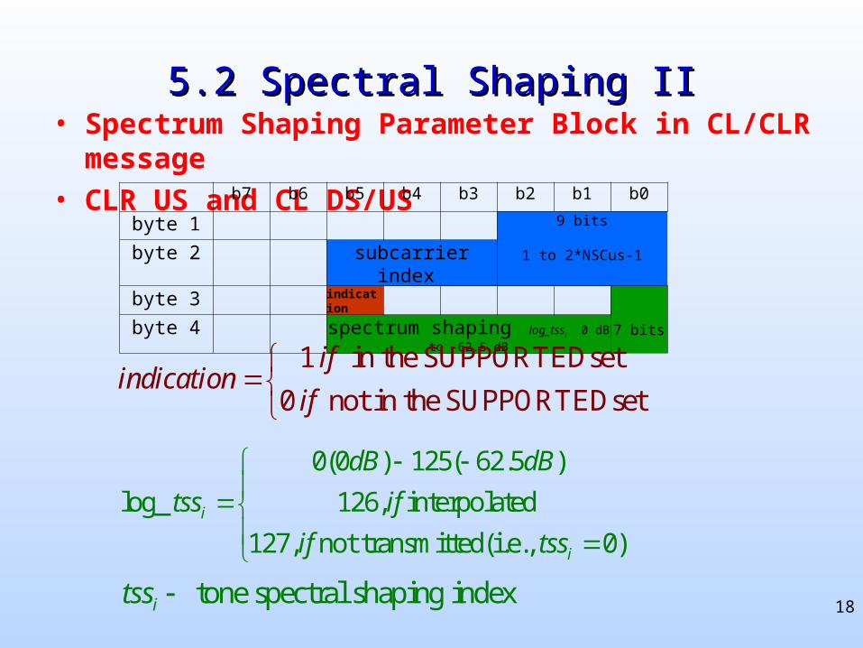
5.2 Spectral Shaping II5.2 Spectral Shaping II• Spectrum Shaping Parameter Block in CL/CLR message
• CLR US and CL DS/US b7 b6 b5 b4 b3 b2 b1 b0
byte 1 9 bits
1 to 2*NSCus-1byte 2 subcarrier index
byte 3 indication
7 bitsbyte 4 spectrum shaping log_tssi 0 dB to -62.5 dB
0(0 ) 125( 62.5 )
log_ 126, interpolated
127, not transmitted(i.e., 0)i
i
dB dB
tss if
if tss
1 in the SUPPORTEDset
0 not in the SUPPORTEDset
ifindication
if
tone spectral shaping indexitss
19
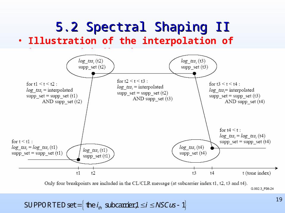
5.2 Spectral Shaping II5.2 Spectral Shaping II• Illustration of the interpolation of log_tssi and indications
SUPPORTEDset the subcarrier,1 1thi i NSCus
20
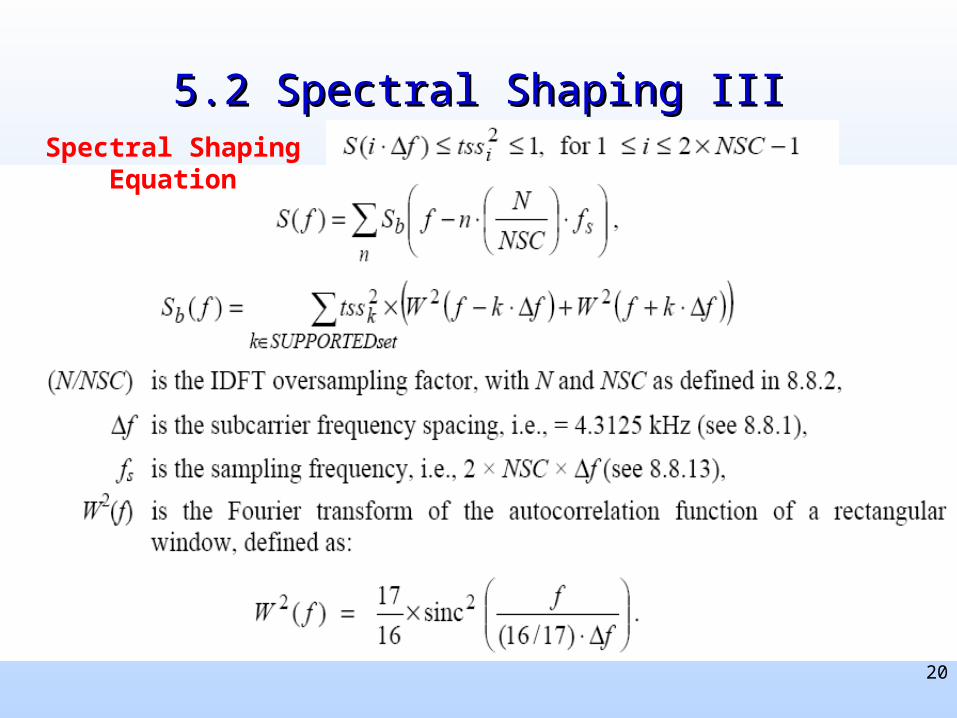
5.2 Spectral Shaping III5.2 Spectral Shaping IIISpectral Shaping Equation
21
5.2 Spectral Shaping IV 5.2 Spectral Shaping IV - Daifeng- Daifeng
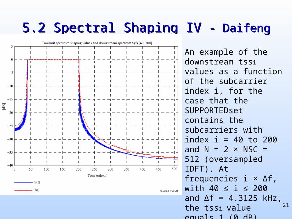
An example of the downstream tssi values as a function of the subcarrier index i, for the case that the SUPPORTEDset contains the subcarriers with index i = 40 to 200 and N = 2 × NSC = 512 (oversampled IDFT). At frequencies i × ∆f, with 40 ≤ i ≤ 200 and ∆f = 4.3125 kHz, the tssi value equals 1 (0 dB).
22
5.2 Spectral Shaping V 5.2 Spectral Shaping V - Daifeng- Daifeng
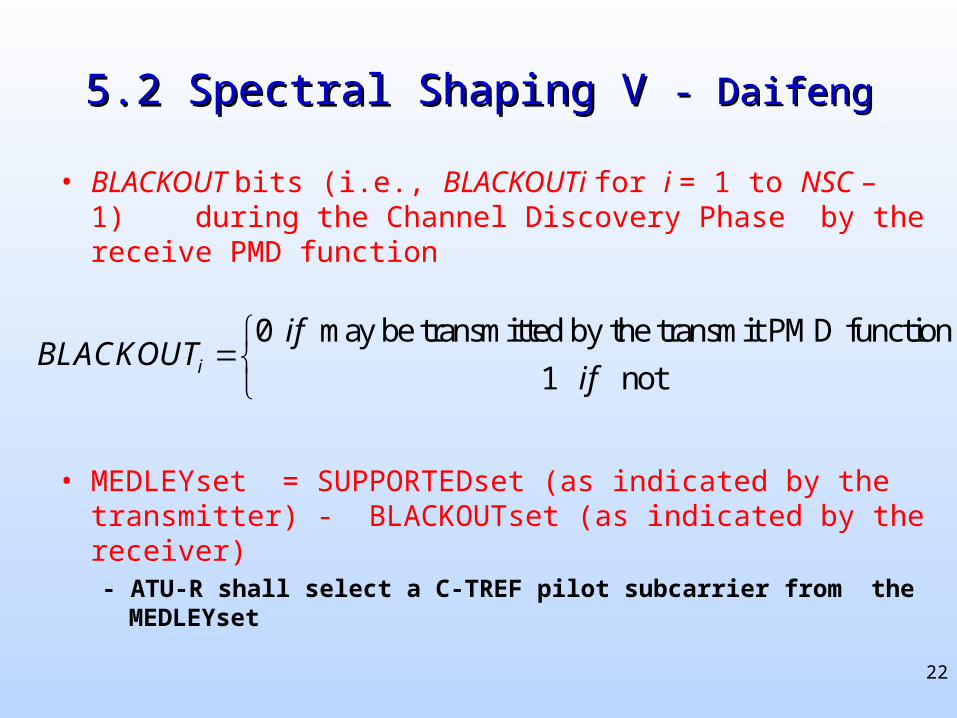
• BLACKOUT bits (i.e., BLACKOUTi for i = 1 to NSC – 1) during the Channel Discovery Phase by the receive PMD function
• MEDLEYset = SUPPORTEDset (as indicated by the transmitter) - BLACKOUTset (as indicated by the receiver)- ATU-R shall select a C-TREF pilot subcarrier from the MEDLEYset
0 may be transmitted by the transmit PMD function
1 noti
ifBLACKOUT
if
23
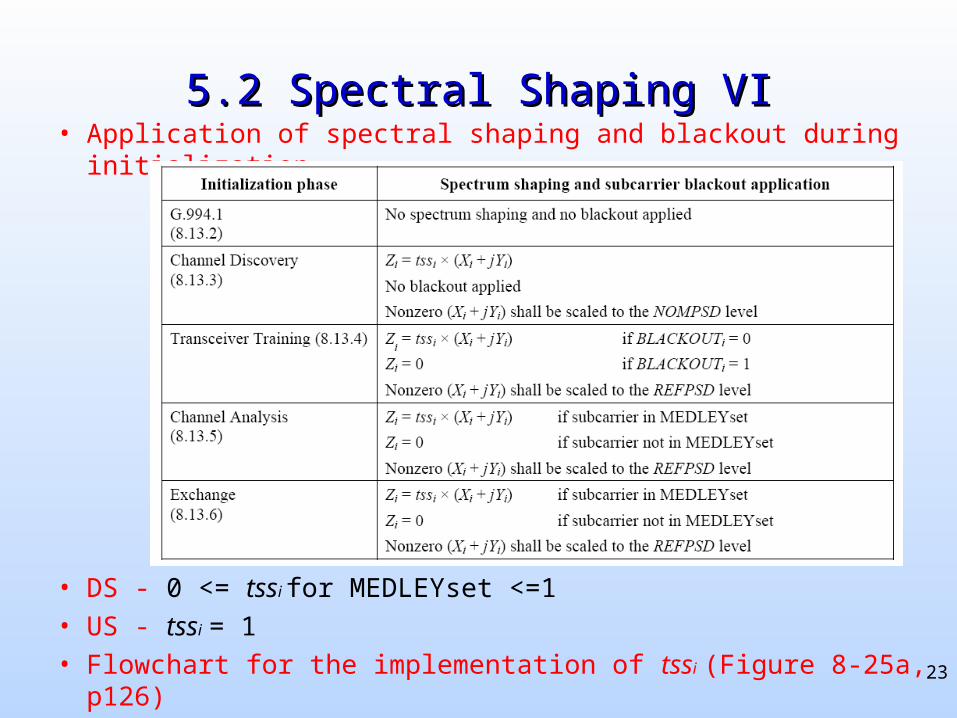
5.2 Spectral Shaping VI5.2 Spectral Shaping VI• Application of spectral shaping and blackout during initialization
• DS - 0 <= tssi for MEDLEYset <=1
• US - tssi = 1
• Flowchart for the implementation of tssi (Figure 8-25a, p126)
24
5.3 Receiver-determined pilot tones I5.3 Receiver-determined pilot tones I
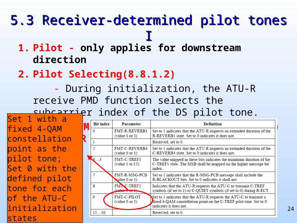
1. Pilot - only applies for downstream direction
2. Pilot Selecting(8.8.1.2)
- During initialization, the ATU-R receive PMD function selects the subcarrier index of the DS pilot tone.
3. R-MSG-FMT(8.13.3.2.10, before R-MSG-PCB) for ATU-R
Set 1 with a fixed 4-QAM constellation point as the pilot tone;Set 0 with the defined pilot tone for each of the ATU-C initialization states
25
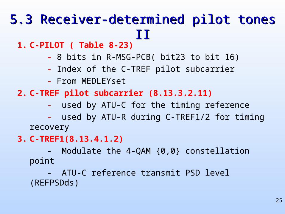
5.3 Receiver-determined pilot tones II5.3 Receiver-determined pilot tones II
1. C-PILOT ( Table 8-23)
- 8 bits in R-MSG-PCB( bit23 to bit 16)
- Index of the C-TREF pilot subcarrier
- From MEDLEYset
2. C-TREF pilot subcarrier (8.13.3.2.11)
- used by ATU-C for the timing reference
- used by ATU-R during C-TREF1/2 for timing recovery
3. C-TREF1(8.13.4.1.2)
- Modulate the 4-QAM {0,0} constellation point
- ATU-C reference transmit PSD level (REFPSDds)
26
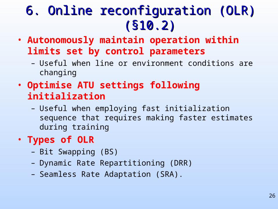
6. Online reconfiguration (OLR) (§10.2)6. Online reconfiguration (OLR) (§10.2)
• Autonomously maintain operation within limits set by control parameters – Useful when line or environment conditions are changing
• Optimise ATU settings following initialization– Useful when employing fast initialization sequence that requires
making faster estimates during training
• Types of OLR– Bit Swapping (BS)
– Dynamic Rate Repartitioning (DRR)
– Seamless Rate Adaptation (SRA).
27
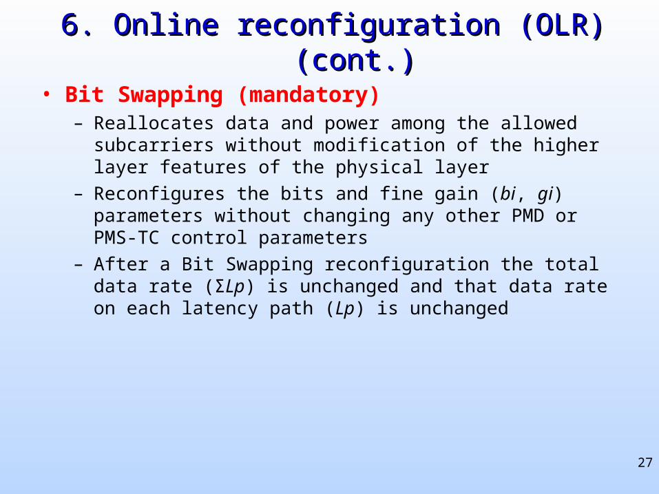
6. Online reconfiguration (OLR) (cont.)6. Online reconfiguration (OLR) (cont.)
• Bit Swapping (mandatory)– Reallocates data and power among the allowed subcarriers without
modification of the higher layer features of the physical layer
– Reconfigures the bits and fine gain (bi, gi) parameters without changing any other PMD or PMS-TC control parameters
– After a Bit Swapping reconfiguration the total data rate (ΣLp) is unchanged and that data rate on each latency path (Lp) is unchanged

28
6. Online reconfiguration (OLR) (cont.)6. Online reconfiguration (OLR) (cont.)
• Dynamic Rate Repartitioning– Reconfigure the data rate allocation between multiple latency paths by
modifying the frame multiplexor control parameters (Lp).
– Can include modifications to the bits and fine gain (bi, gi) parameters, reallocating bits among the subcarriers.
– Does not modify the total data rate (ΣLp) but does modify the individual latency path data rates (Lp)
– Performed in response to higher layer commands, and is thus an application option

29
6. Online reconfiguration (OLR) (cont.)6. Online reconfiguration (OLR) (cont.)
• Seamless Rate Adaptation (SRA)– Used to reconfigure the total data rate (ΣLp) by modifying the frame
multiplexor control parameters (Lp) and modifications to the bits and fine gains (bi, gi) parameters
• Since the total data rate is modified, at least one latency path (or more) will have a new data rate (Lp) after the SRA
– Allows modulation parameters to change without modifying framing parameters
• Prevents frame desynchronization which causes uncorrectable bit errors or system retraining
– Used in response to higher layer commands, thus is an application option
– Any ATU that implements the optional PMD short initialization procedure should implement SRA operations
• This ensures the ATU is able to adapt to the channel conditions which were not as accurately estimated
30
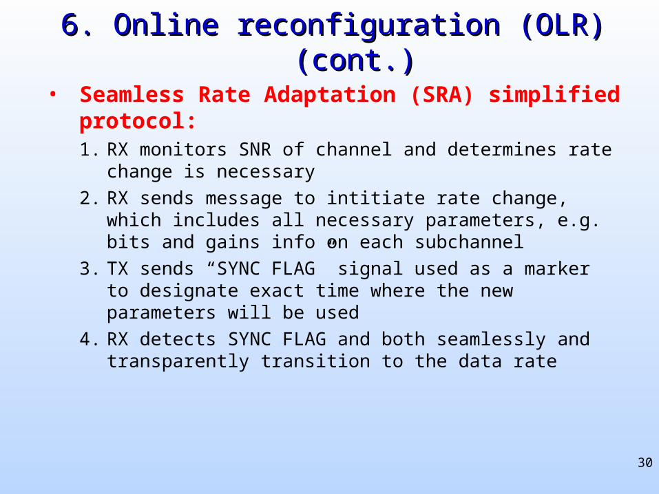
6. Online reconfiguration (OLR) (cont.)6. Online reconfiguration (OLR) (cont.)
• Seamless Rate Adaptation (SRA) simplified protocol:1. RX monitors SNR of channel and determines rate change is
necessary
2. RX sends message to intitiate rate change, which includes all necessary parameters, e.g. bits and gains info on each subchannel
3. TX sends “SYNC FLAG” signal used as a marker to designate exact time where the new parameters will be used
4. RX detects SYNC FLAG and both seamlessly and transparently transition to the data rate
31
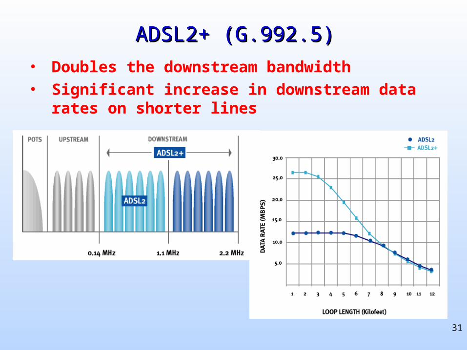
ADSL2+ (G.992.5)ADSL2+ (G.992.5)
• Doubles the downstream bandwidth
• Significant increase in downstream data rates on shorter lines
32
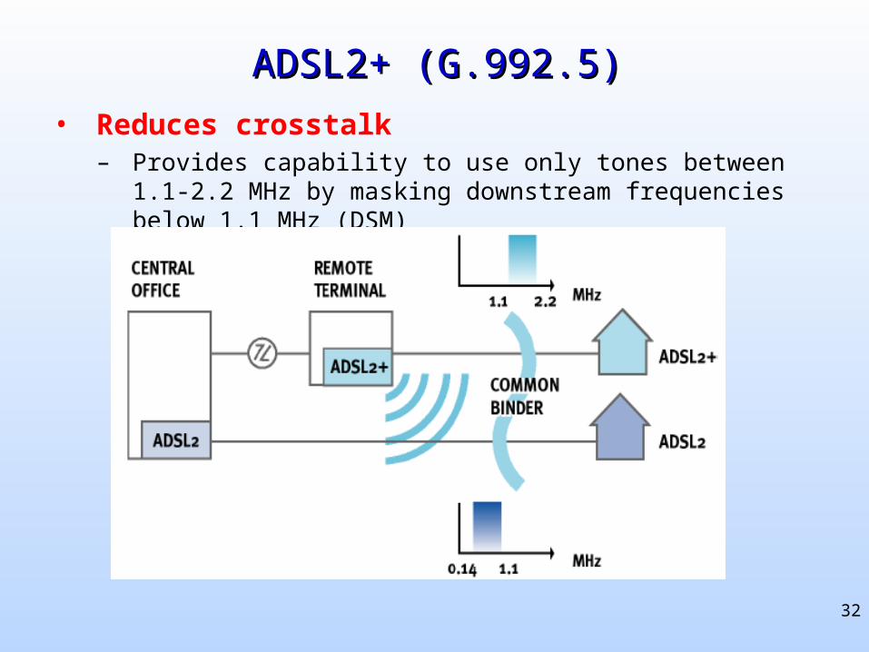
ADSL2+ (G.992.5)ADSL2+ (G.992.5)
• Reduces crosstalk– Provides capability to use only tones between 1.1-2.2 MHz by
masking downstream frequencies below 1.1 MHz (DSM)
33
Backup SlidesBackup Slides
34
ADSL2 improvements over ADSLADSL2 improvements over ADSL
• Application-related features– Improved application support for an all digital mode of operation and
voice over ADSL operation;
– Packet TPS-TC1 function, in addition to the existing Synchronous Transfer Mode (STM) and Asynchronous TM (ATM)
– Mandatory support of 8 Mbit/s downstream and 800 kbit/s upstream for TPS-TC function #0 and frame bearer #0;
– Support for Inverse Multiplexing for ATM (IMA) in the ATM TPS-TC;
– Improved configuration capability for each TPS-TC with configuration of latency, BER and minimum, maximum and reserved data rate.
1Transport Protocol Specific-Transmission Convergence
35
ADSL2 improvements over ADSL (cont.)ADSL2 improvements over ADSL (cont.)
• PMS-TC1 related features– A more flexible framing, including support for up to 4 frame bearers, 4
latency paths;
– Parameters allowing enhanced configuration of the overhead channel;
– Frame structure with
• Receiver selected coding parameters;
• Optimized use of RS coding gain;
• Configurable latency and bit error ratio;
– OAM2 protocol to retrieve more detailed performance monitoring information;
– Enhanced on-line reconfiguration capabilities including dynamic rate repartitioning.
1 Physical Media Specific-Transmission Convergence2 Operations, Administration, and Maintenance
36
ADSL2 improvements over ADSL (cont.)ADSL2 improvements over ADSL (cont.)• Physical Media Dependent (PMD) related features
– New line diagnostics procedures for both successful and unsuccessful initialization scenarios, loop characterization and troubleshooting;
– Enhanced on-line reconfiguration capabilities including bitswaps and seamless rate adaptation;
– Optional short initialization sequence for recovery from errors or fast resumption of operation;
– Optional seamless rate adaptation with line rate changes during showtime;
– Improved robustness against bridged taps with RX determined pilot;– Improved transceiver training with exchange of detailed transmit signal
characteristics;– Improved SNR measurement during channel analysis;– Subcarrier blackout to allow RFI measurement during initialization and
SHOWTIME;– Improved performance with mandatory support of trellis coding, one-bit
constellations, and optional data modulated on the pilot-tone
37
ADSL2 improvements over ADSL (cont.)ADSL2 improvements over ADSL (cont.)
• PMD related features (cont.)– Improved RFI robustness with receiver determined tone ordering;
– Improved transmit power cutback possibilities
– Improved Initialization with RX/TX controlled duration of init. states;
– Improved Initialization with RX-determined carriers for modulation of messages;
– Improved channel identification capability with spectral shaping during Channel Discovery and Transceiver Training;
– Mandatory transmit power reduction to minimize excess margin under management layer control;
– Power saving feature with new L2 low power state and L3 idle state;
– Spectrum control with individual tone masking under operator control through CO-Management Information Base;
– Improved conformance testing including increase in data rates for many existing tests.
38
BibliographyBibliography[ADSL2] ITU-T Standard G.992.3, Asymmetric digital subscriber line transceivers 2
(ADSL2), Feb. 2004
[ADSL2white] ADSL2 and ADSL2plus-The new ADSL standards. Online: http://www.dslforum.org/aboutdsl/ADSL2_wp.pdf, Mar. 2003
[Wei87] L.-F.Wei, “Trellis-coded modulation with multidimensional constellations,” IEEE Trans. Inform. Theory, vol. IT-33, pp. 483-501, July 1987.
[IMA99] ATM Forum Specification af.phy-0086.001, Inverse Multiplexing for ATM (IMA), Version 1.1., Mar. 1999