Embed Size (px)
Citation preview
AASHTO Bridge Element Inspection Guide Manual
1st Edition, 2010
(COVER DESIGN to be done by AASHTO Publications)
AASHTO Bridge Element Inspection Manual
2
© XXX by the American Association of State Highway and Transportation Officials. All rights reserved. Printed in the United States of America. This book or parts thereof may not be reproduced in any form without written permission of the publishers.
ISBN: XXXXX
AASHTO Bridge Element Inspection Manual
3
AMERICAN ASSOICATION OF STATE HIGHWAY
AND TRANSPORTATION OFFICIALS
2010–2011 Executive Committee
President: Vice President: Secretary/Treasurer: Regional Representatives
AASHTO Bridge Element Inspection Manual
4
AMERICAN ASSOCIATION OF STATE HIGHWAY
AND TRANSPORTATION OFFICIALS SUBCOMMITTEE ON BRIDGES AND STRUCTURES
Chair:
Vice Chair:
Secretary:
(CURRENT ROSTER)
AASHTO Bridge Element Inspection Manual
5
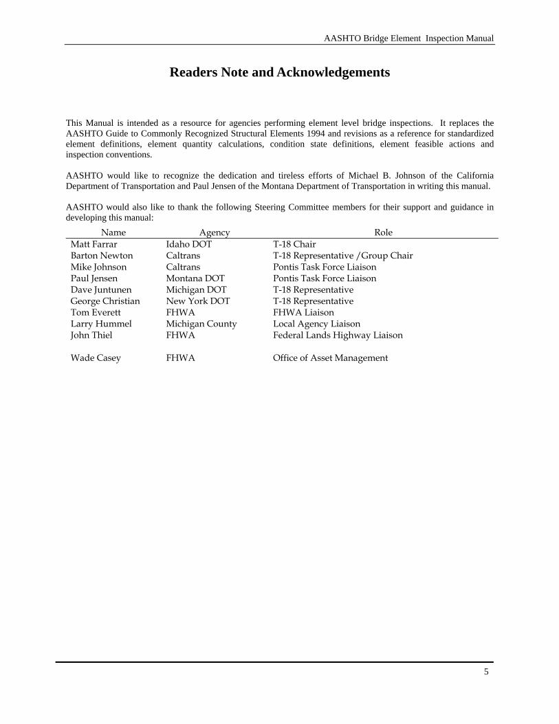
Readers Note and Acknowledgements
This Manual is intended as a resource for agencies performing element level bridge inspections. It replaces the AASHTO Guide to Commonly Recognized Structural Elements 1994 and revisions as a reference for standardized element definitions, element quantity calculations, condition state definitions, element feasible actions and inspection conventions. AASHTO would like to recognize the dedication and tireless efforts of Michael B. Johnson of the California Department of Transportation and Paul Jensen of the Montana Department of Transportation in writing this manual. AASHTO would also like to thank the following Steering Committee members for their support and guidance in developing this manual:
Name Agency Role Matt Farrar Idaho DOT T-18 Chair Barton Newton Caltrans T-18 Representative /Group Chair Mike Johnson Caltrans Pontis Task Force Liaison Paul Jensen Montana DOT Pontis Task Force Liaison Dave Juntunen Michigan DOT T-18 Representative George Christian New York DOT T-18 Representative Tom Everett FHWA FHWA Liaison Larry Hummel Michigan County Local Agency Liaison John Thiel
FHWA
Federal Lands Highway Liaison
Wade Casey FHWA Office of Asset Management
AASHTO Bridge Element Inspection Manual
6
Table of Contents
Readers Note and Acknowledgements...................................................................................................................................5
INTRODUCTION ...................................................................................................................................................................9
Section 1 Background ....................................................................................................................................................11
1.1 Condition Assessment Philosophy: Multi-Path And Defect Concepts......................................................11 1.2 National Bridge Elements (NBE)...............................................................................................................11 1.3 Bridge Management Elements (BME) .......................................................................................................11 1.4 Agency Developed Elements .....................................................................................................................11 1.5 How To Use This Manual ..........................................................................................................................12 1.6 REFERENCES...........................................................................................................................................12
Section 2 Element Location Matrix ..............................................................................................................................13
2.1 National Bridge Elements ..........................................................................................................................13 2.1.1 Decks/Slabs................................................................................................................................................13
2.1.1 Superstructure ........................................................................................................................14 2.1.2 Substructure ...........................................................................................................................14
2.2 Bridge Management Elements ...................................................................................................................15 2.2.1 Decks/Slabs............................................................................................................................15 2.2.2 Wearing Surfaces and Protection Systems.............................................................................15 2.2.3 Smart Flags (Defect Flags) ....................................................................................................16
Detailed Element Descriptions..............................................................................................................................................17
3.1 National Bridge Elements ..........................................................................................................................17 3.1.1 Decks/Slabs............................................................................................................................17 3.1.2 Superstructure ........................................................................................................................25 3.1.3 Girders ...................................................................................................................................25 3.1.4 Stringers.................................................................................................................................34 3.1.5 Trusses / Arches.....................................................................................................................39 3.1.6 Floor Beams...........................................................................................................................49 3.1.7 Miscellaneous Superstructure Elements ................................................................................55 3.1.8 Substructure Elements ...........................................................................................................62 3.1.9 Columns/Pile/Pier Wall .........................................................................................................62 3.1.10 Abutments..............................................................................................................................73 3.1.11 Submerged Pile/Caps/Footings..............................................................................................80 3.1.12 Culverts..................................................................................................................................90 3.1.13 Bearings .................................................................................................................................97 3.1.14 Bridge Rail...........................................................................................................................104
3.2 Bridge Management Elements .................................................................................................................112 3.2.1 Joints....................................................................................................................................112 3.2.2 Approach Slabs....................................................................................................................120 3.2.3 Smart Flags (Defect Flags) ..................................................................................................124 3.2.4 Protective Systems...............................................................................................................128 3.2.5 Environmental Factors (States)............................................................................................134
AASHTO Bridge Element Inspection Manual
7
Appendix
Appendix A Agency Developed Elements ............................................................................................................137 A.1 Agency Defined Sub-sets of the National Bridge Elements .........................................................137 A.2 Agency Defined Sub-sets of the Bridge Management Elements ..................................................137 A.3 Independent Agency Developed Elements ...................................................................................138
Appendix B Inspection Examples..........................................................................................................................141 B.1 Timber Bridge...............................................................................................................................141 B.2 Two Span Concrete AASTHTO Girder Structure ........................................................................143 B.3 Painted Steel Truss........................................................................................................................147
Appendix C Element Grouping .............................................................................................................................152 C.1 National Bridge Elements (NBE)..................................................................................................154 C.2 Bridge Management Elements (BME)..........................................................................................155 C.3 Obsolete Elements from CoRe Guide ...........................................................................................156
Appendix D Migration from CoRe Elements ........................................................................................................157 D.1 Deck Elements ..............................................................................................................................157 D.1.1 Concrete...............................................................................................................................157 D.1.2 Steel .....................................................................................................................................162 D.1.3 Timber .................................................................................................................................165 D.2 Superstructure, Substructure and Culvert (SSC) Elements ...........................................................167 D.2.1 Steel .....................................................................................................................................167 D.2.2 Concrete...............................................................................................................................171 D.2.3 Timber .................................................................................................................................173 D.3 Other Elements .............................................................................................................................174 D.3.1 Joints....................................................................................................................................174 D.3.2 Bearings ...............................................................................................................................175 D.3.3 Traffic Rails .........................................................................................................................176
AASHTO Bridge Element Inspection Manual
8
[BLANK PAGE]

AASHTO Bridge Element Inspection Manual
9
INTRODUCTION
The proper assessment of the condition of bridge elements is the cornerstone of sound bridge management. The introduction of element inspection condition methods in the early 1990’s represented a significant advancement in the bridge inspection practice and has been adopted by the vast majority of all State Transportation Departments in the United States. Bridge owners nationwide have recognized the benefits of detailed condition assessments through the use of the raw inspection information, expanded performance measures and bridge management system deterioration forecasting and evaluation. As the use of element level inspection techniques has proliferated, the need for improvements has been identified. This manual incorporates improvements through changes in the measurement units of decks and slabs, the development of a wearing surface element, the standardization of the number of element states, the development of a protective coating element, and the incorporation of expanded element Smart Flags. The goal of this manual is to completely capture the condition of bridges in a simple way that can be standardized across the nation while providing the flexibility to be adapted to both large and small agency settings. This manual is not intended to supplant proper training or the exercise of engineering judgment by the inspector or professional engineer.
AASHTO Bridge Element Inspection Manual
10
[BLANK PAGE]
AASHTO Bridge Element Inspection Manual
11
Section 1 Background
1.1 Condition Assessment Philosophy: Multi-Path And Defect Concepts
The Bridge Element Inspection Manual builds on the element level condition assessment methods developed in the AASHTO Guide for Commonly Recognized Structural Elements. Improvements have been made to fully capture the condition of the elements by reconfiguring the element language to utilize multiple distress paths within the defined condition states. The multi-path distress language provides the means to fully incorporate all possible defects within the overall condition assessment of the element. The overall condition of an element can be utilized in this aggregate form or broken down into specific defects present as desired by the agency for Bridge Management System use. The Bridge Element Inspection Manual provides a comprehensive set of bridge elements that is designed to be flexible in nature to satisfy the needs of all agencies. The complete set of elements capture the components necessary for an agency to manage all aspects of the bridge inventory utilizing the full capability of a Bridge Management System (BMS). The element set presented within includes two element types identified as National Bridge Elements (NBE) or Bridge Management Elements (BME). The combination of these two element types comprise the full AASHTO element set. All of the elements, whether they are NBE or BME, have the same general requirement:
1. Standard number of condition states 2. The standard number of condition states are comprised of good, fair, poor and severe general descriptions
1.2 National Bridge Elements (NBE)
The National Bridge Elements represent the primary structural components of bridges necessary to determine the overall condition and safety of the primary load carrying members. The NBE’s are a refinement of the deck, superstructure, substructures and culvert condition ratings defined in the Federal Highway Administration’s Recording and Coding Guide for the Structure Inventory and Appraisal of the Nation's Bridges. Additional elements included in this section are bridge rail and bearings. The National Bridge Elements are designed to remain consistent from agency to agency across the country in order to facilitate the capture of bridge element condition at the national level.
1.3 Bridge Management Elements (BME)
Bridge Management Elements include components of bridges such as joints, wearing surfaces and protective coating systems that are typically managed by agencies utilizing Bridge Management Systems. The Bridge Management Elements represent a recommended set of condition assessment language that can be modified to suit the agencies needs as these elements are not intended to be utilized for the purposes of national policy making. The BME’s defined within this manual were purposefully left fairly general in nature to provide the flexibility to develop agency specific elements that best suit the local bridge preservation practices.
1.4 Agency Developed Elements
The elements presented within provide the flexibility for an agency to define custom elements in accordance with the defined element framework that can be sub-elements of NBE’s, BME’s or state defined elements without ties to the elements contained in this manual. By defining a comprehensive set of bridge elements necessary for robust bridge management and the minimum set of elements necessary to assess the condition of primary components of bridges, the Bridge Element Inspection Manual provides a flexible element set that can be tailored to the needs of all agencies.
AASHTO Bridge Element Inspection Manual
12
1.5 How To Use This Manual
Bridge inspection based on this manual consists of defining the elements (pieces of the bridge) and total quantities that exist at each bridge. The condition of each element is determined by performing a field inspection and recording quantities of the element that have identified defects that correlate to the severity of the defects defined in the particular condition state definition of this Manual. The condition assessment is complete when the appropriate portion of the total quantity is stratified over the defined condition states. For agencies utilizing bridge management systems, the appropriate element Smart Flags and environment shall be recorded for use in deterioration modeling. This manual attempts to cover the vast majority of all bridge elements found on highway bridges in the United States. An inspector may find materials or elements that are not defined during the course of their inspection. In these cases the inspector should use judgment to select the closest element match. In a similar vain, there may be cases when the specific condition observed in the field is not defined in this manual. In these cases, the inspector should use the general description of the condition states to determine the appropriate condition. The granularity of the defect details is typically eliminated for condition state 4 as this state is reserved for severe conditions that are beyond those specific defects defined in states 1 through 3 and may often have load capacity implications.
1.6 REFERENCES
FHWA. 1995. Recording and Coding Guide for the Structure Inventory and Appraisal of the Nation’s Bridges. Federal Highway Administration, U.S. Department of Transportation, Washington, DC. AASHTO. 2002 with Interims. Guide for Commonly Recognized (CoRe) Structural Elements, CORE-1-I1. American Association of State Highway and Transportation Officials, Washington, DC. AASHTO. 2009. “PONTIS” Release 5.1, User’s Manual. American Association of State Highway and Transportation Officials, Washington, DC. FHWA. 2006. Bridge Inspector’s Reference Manual. Federal Highway Administration. U.S. Department of Transportation, Washington, DC. NCHRP. 1999. “BRIDGIT” Bridge Management System Users Manual and Technical Manual, NCHRP Project 12-28 (A and B1), Transportation Research Board, National Research Council, Washington, DC. NCHRP. 2007. Multi-Objective Optimization for Bridge Management, NCHRP Report 590, Transportation Research Board, National Research Council, Washington, DC.
AASHTO Bridge Element Inspection Manual
13
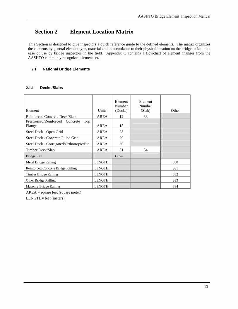
Section 2 Element Location Matrix
This Section is designed to give inspectors a quick reference guide to the defined elements. The matrix organizes the elements by general element type, material and in accordance to their physical location on the bridge to facilitate ease of use by bridge inspectors in the field. Appendix C contains a flowchart of element changes from the AASHTO commonly recognized element set.
2.1 National Bridge Elements
2.1.1 Decks/Slabs
Element Units
ElementNumber(Decks)
Element Number (Slab)
Other Reinforced Concrete Deck/Slab AREA 12 38 Prestressed/Reinforced Concrete Top Flange AREA 15
Steel Deck - Open Grid AREA 28
Steel Deck - Concrete Filled Grid AREA 29
Steel Deck - Corrugated/Orthotropic/Etc. AREA 30
Timber Deck/Slab AREA 31 54
Bridge Rail Other
Metal Bridge Railing LENGTH 330 Reinforced Concrete Bridge Railing LENGTH 331 Timber Bridge Railing LENGTH 332 Other Bridge Railing LENGTH 333 Masonry Bridge Railing LENGTH 334 AREA = square feet (square meter)
LENGTH= feet (meters)
AASHTO Bridge Element Inspection Manual
14
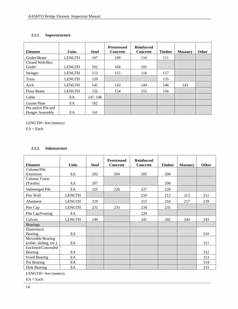
2.1.1 Superstructure
Element Units Steel Prestressed Concrete
Reinforced Concrete Timber Masonry Other
Girder/Beam LENGTH 107 109 110 111 Closed Web/Box Girder LENGTH 102 104 105 Stringer LENGTH 113 115 116 117 Truss LENGTH 120 135 Arch LENGTH 141 143 144 146 145 Floor Beam LENGTH 152 154 155 156 Cable EA 147, 148 Gusset Plate EA 162 Pin and/or Pin and Hanger Assembly EA 161 LENGTH= feet (meters) EA = Each
2.1.2 Substructure
Element Units Steel Prestressed Concrete
Reinforced Concrete Timber Masonry Other
Column/Pile Extension EA 202 204 205 206 Column Tower (Trestle) EA 207 208 Submerged Pile EA 225 226 227 228 Pier Wall LENGTH 210 212 213 211 Abutment LENGTH 219 215 216 217 218 Pier Cap LENGTH 231 233 234 235 Pile Cap/Footing EA 220 Culvert LENGTH 240 241 242 244 243 Bearings Elastomeric Bearing EA 310 Moveable Bearing (roller, sliding, etc.) EA 311 Enclosed/Concealed Bearing EA 312 Fixed Bearing EA 313 Pot Bearing EA 314 Disk Bearing EA 315 LENGTH= feet (meters) EA = Each
AASHTO Bridge Element Inspection Manual
15
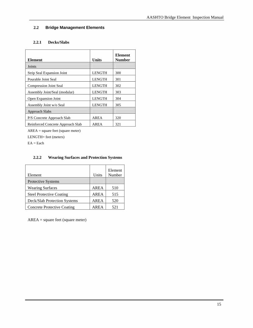
2.2 Bridge Management Elements
2.2.1 Decks/Slabs
Element Units Element Number
Joints
Strip Seal Expansion Joint LENGTH 300
Pourable Joint Seal LENGTH 301
Compression Joint Seal LENGTH 302
Assembly Joint/Seal (modular) LENGTH 303
Open Expansion Joint LENGTH 304
Assembly Joint w/o Seal LENGTH 305
Approach Slabs
P/S Concrete Approach Slab AREA 320
Reinforced Concrete Approach Slab AREA 321
AREA = square feet (square meter)
LENGTH= feet (meters)
EA = Each
2.2.2 Wearing Surfaces and Protection Systems
Element Units ElementNumber
Protective Systems Wearing Surfaces AREA 510 Steel Protective Coating AREA 515 Deck/Slab Protection Systems AREA 520 Concrete Protective Coating AREA 521 AREA = square feet (square meter)
AASHTO Bridge Element Inspection Manual
16
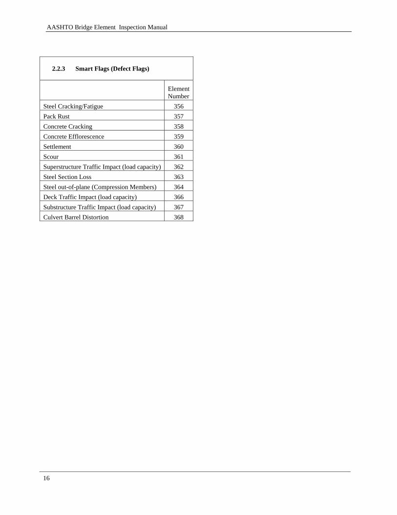
2.2.3 Smart Flags (Defect Flags)
ElementNumber
Steel Cracking/Fatigue 356 Pack Rust 357 Concrete Cracking 358 Concrete Efflorescence 359 Settlement 360 Scour 361 Superstructure Traffic Impact (load capacity) 362 Steel Section Loss 363 Steel out-of-plane (Compression Members) 364 Deck Traffic Impact (load capacity) 366 Substructure Traffic Impact (load capacity) 367 Culvert Barrel Distortion 368

AASHTO Bridge Element Inspection Manual
17
Detailed Element Descriptions
This section describes the elements detailed use in inspection and bridge management. The detailed description is broken down into six sections:
1. Description – Detailed identification of the element 2. Quantity Calculation – General guideline on how to collect the quantity of the element 3. Condition State Definitions – Defect description and severity 4. Feasible Actions – The actions an agency can take to remove the defect (these are needed for Bridge
Management Systems) 5. Element Commentary – additional considerations for the inspector during data collection 6. Element Definitions – Guidelines to the inspector for defect severity categorization
The elements listed in this section will be divided into NBE and BME.
3.1 National Bridge Elements
This section describes in detail those elements that are primary structure elements
3.1.1 Decks/Slabs
These elements describe the component that is transferring load from the vehicle to the bridge. This section does not include secondary deck elements such as joints, deck/slab protection systems or wearing surfaces. Deck structures transmit the loads into superstructure systems. Slab elements transmit the load into the substructure. Structures that include slab elements typically do not have superstructure elements. These elements transmit traffic loads directly into the substructure. All deck or slab elements can be supplemented with one or more associated protection system or wearing surface elements.

AASHTO Bridge Element Inspection Manual
18
[BLANK PAGE]
AASHTO Bridge Element Inspection Manual
19
Element # 12/38
Reinforced Concrete Deck/Slab Square Feet (Square Meters)
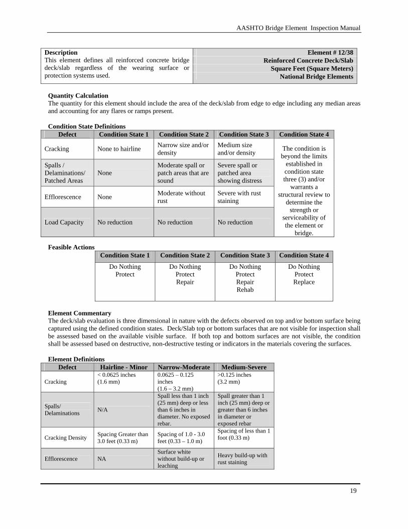
Description This element defines all reinforced concrete bridge deck/slab regardless of the wearing surface or protection systems used. National Bridge Elements
Quantity Calculation The quantity for this element should include the area of the deck/slab from edge to edge including any median areas and accounting for any flares or ramps present. Condition State Definitions
Defect Condition State 1 Condition State 2 Condition State 3 Condition State 4
Cracking None to hairline Narrow size and/or density
Medium size and/or density
Spalls / Delaminations/ Patched Areas
None Moderate spall or patch areas that are sound
Severe spall or patched area showing distress
Efflorescence None Moderate without rust
Severe with rust staining
Load Capacity No reduction No reduction No reduction
The condition is beyond the limits
established in condition state three (3) and/or
warrants a structural review to
determine the strength or
serviceability of the element or
bridge. Feasible Actions
Condition State 1 Condition State 2 Condition State 3 Condition State 4 Do Nothing
Protect Do Nothing
Protect Repair
Do Nothing Protect Repair Rehab
Do Nothing Protect Replace
Element Commentary The deck/slab evaluation is three dimensional in nature with the defects observed on top and/or bottom surface being captured using the defined condition states. Deck/Slab top or bottom surfaces that are not visible for inspection shall be assessed based on the available visible surface. If both top and bottom surfaces are not visible, the condition shall be assessed based on destructive, non-destructive testing or indicators in the materials covering the surfaces. Element Definitions
Defect Hairline - Minor Narrow-Moderate Medium-Severe
Cracking < 0.0625 inches (1.6 mm)
0.0625 – 0.125 inches (1.6 – 3.2 mm)
>0.125 inches (3.2 mm)
Spalls/ Delaminations N/A
Spall less than 1 inch (25 mm) deep or less than 6 inches in diameter. No exposed rebar.
Spall greater than 1 inch (25 mm) deep or greater than 6 inches in diameter or exposed rebar
Cracking Density Spacing Greater than 3.0 feet (0.33 m)
Spacing of 1.0 - 3.0 feet (0.33 – 1.0 m)
Spacing of less than 1 foot (0.33 m)
Efflorescence NA Surface white without build-up or leaching
Heavy build-up with rust staining
AASHTO Bridge Element Inspection Manual
20
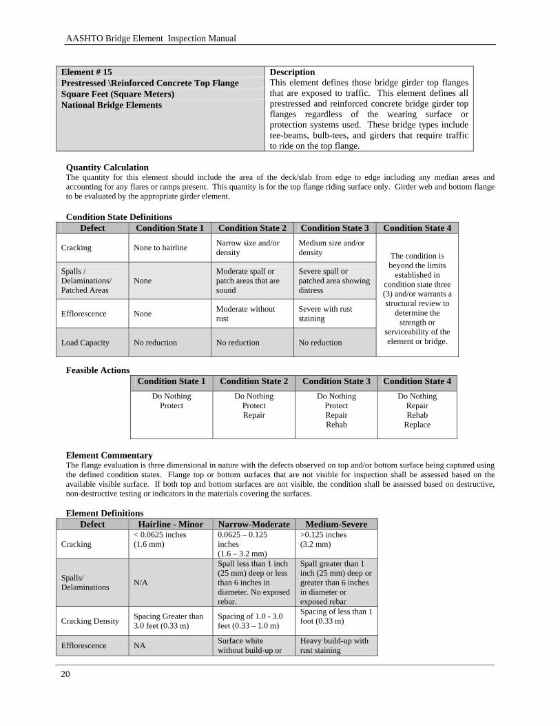
Element # 15 Prestressed \Reinforced Concrete Top Flange Square Feet (Square Meters) National Bridge Elements
Description This element defines those bridge girder top flanges that are exposed to traffic. This element defines all prestressed and reinforced concrete bridge girder top flanges regardless of the wearing surface or protection systems used. These bridge types include tee-beams, bulb-tees, and girders that require traffic to ride on the top flange.
Quantity Calculation The quantity for this element should include the area of the deck/slab from edge to edge including any median areas and accounting for any flares or ramps present. This quantity is for the top flange riding surface only. Girder web and bottom flange to be evaluated by the appropriate girder element. Condition State Definitions
Defect Condition State 1 Condition State 2 Condition State 3 Condition State 4
Cracking None to hairline Narrow size and/or density
Medium size and/or density
Spalls / Delaminations/ Patched Areas
None Moderate spall or patch areas that are sound
Severe spall or patched area showing distress
Efflorescence None Moderate without rust
Severe with rust staining
Load Capacity No reduction No reduction No reduction
The condition is beyond the limits
established in condition state three (3) and/or warrants a structural review to
determine the strength or
serviceability of the element or bridge.
Feasible Actions
Condition State 1 Condition State 2 Condition State 3 Condition State 4 Do Nothing
Protect Do Nothing
Protect Repair
Do Nothing Protect Repair Rehab
Do Nothing Repair Rehab
Replace
Element Commentary The flange evaluation is three dimensional in nature with the defects observed on top and/or bottom surface being captured using the defined condition states. Flange top or bottom surfaces that are not visible for inspection shall be assessed based on the available visible surface. If both top and bottom surfaces are not visible, the condition shall be assessed based on destructive, non-destructive testing or indicators in the materials covering the surfaces. Element Definitions
Defect Hairline - Minor Narrow-Moderate Medium-Severe
Cracking < 0.0625 inches (1.6 mm)
0.0625 – 0.125 inches (1.6 – 3.2 mm)
>0.125 inches (3.2 mm)
Spalls/ Delaminations N/A
Spall less than 1 inch (25 mm) deep or less than 6 inches in diameter. No exposed rebar.
Spall greater than 1 inch (25 mm) deep or greater than 6 inches in diameter or exposed rebar
Cracking Density Spacing Greater than 3.0 feet (0.33 m)
Spacing of 1.0 - 3.0 feet (0.33 – 1.0 m)
Spacing of less than 1 foot (0.33 m)
Efflorescence NA Surface white without build-up or
Heavy build-up with rust staining
AASHTO Bridge Element Inspection Manual
21
leaching
Element #28
Steel Deck With Open Grid Square Feet (Square Meters)
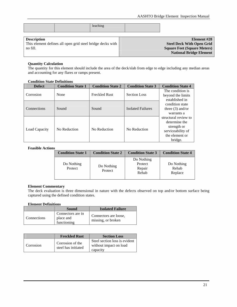
Description This element defines all open grid steel bridge decks with no fill.
National Bridge Element
Quantity Calculation The quantity for this element should include the area of the deck/slab from edge to edge including any median areas and accounting for any flares or ramps present. Condition State Definitions
Defect Condition State 1 Condition State 2 Condition State 3 Condition State 4
Corrosion None Freckled Rust Section Loss
Connections Sound Sound Isolated Failures
Load Capacity No Reduction No Reduction No Reduction
The condition is beyond the limits
established in condition state three (3) and/or
warrants a structural review to
determine the strength or
serviceability of the element or
bridge. Feasible Actions
Condition State 1 Condition State 2 Condition State 3 Condition State 4
Do Nothing Protect
Do Nothing Protect
Do Nothing Protect Repair Rehab
Do Nothing Rehab
Replace
Element Commentary The deck evaluation is three dimensional in nature with the defects observed on top and/or bottom surface being captured using the defined condition states. Element Definitions
Sound Isolated Failure
Connections Connectors are in place and functioning
Connectors are loose, missing, or broken
Freckled Rust Section Loss
Corrosion Corrosion of the steel has initiated
Steel section loss is evident without impact on load capacity
AASHTO Bridge Element Inspection Manual
22
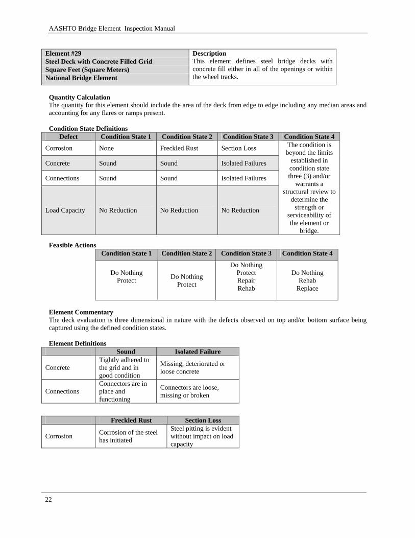
Element #29 Steel Deck with Concrete Filled Grid Square Feet (Square Meters) National Bridge Element
Description This element defines steel bridge decks with concrete fill either in all of the openings or within the wheel tracks.
Quantity Calculation The quantity for this element should include the area of the deck from edge to edge including any median areas and accounting for any flares or ramps present. Condition State Definitions
Defect Condition State 1 Condition State 2 Condition State 3 Condition State 4
Corrosion None Freckled Rust Section Loss
Concrete Sound Sound Isolated Failures
Connections Sound Sound Isolated Failures
Load Capacity No Reduction No Reduction No Reduction
The condition is beyond the limits
established in condition state three (3) and/or
warrants a structural review to
determine the strength or
serviceability of the element or
bridge. Feasible Actions
Condition State 1 Condition State 2 Condition State 3 Condition State 4
Do Nothing Protect
Do Nothing Protect
Do Nothing Protect Repair Rehab
Do Nothing Rehab
Replace
Element Commentary The deck evaluation is three dimensional in nature with the defects observed on top and/or bottom surface being captured using the defined condition states. Element Definitions
Sound Isolated Failure
Concrete Tightly adhered to the grid and in good condition
Missing, deteriorated or loose concrete
Connections Connectors are in place and functioning
Connectors are loose, missing or broken
Freckled Rust Section Loss
Corrosion Corrosion of the steel has initiated
Steel pitting is evident without impact on load capacity
AASHTO Bridge Element Inspection Manual
23
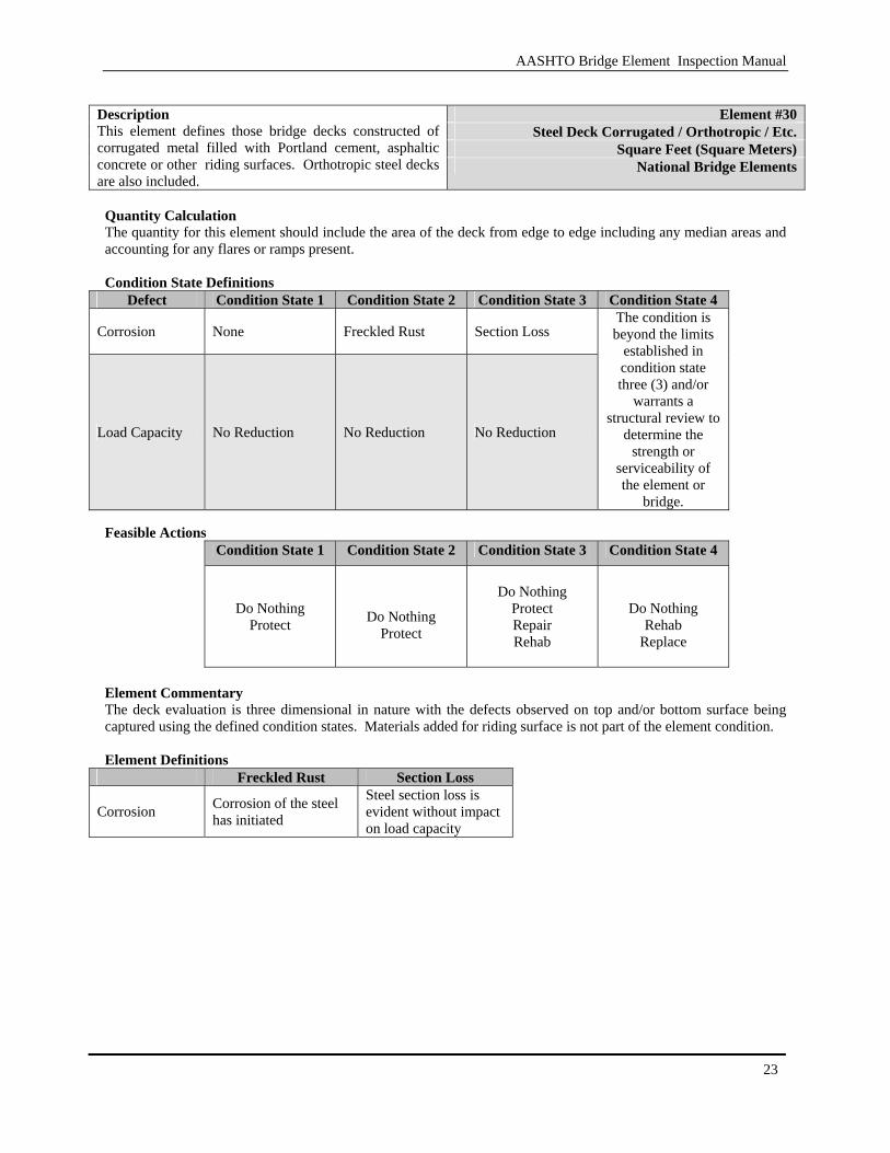
Element #30
Steel Deck Corrugated / Orthotropic / Etc. Square Feet (Square Meters)
Description This element defines those bridge decks constructed of corrugated metal filled with Portland cement, asphaltic concrete or other riding surfaces. Orthotropic steel decks are also included.
National Bridge Elements
Quantity Calculation The quantity for this element should include the area of the deck from edge to edge including any median areas and accounting for any flares or ramps present. Condition State Definitions
Defect Condition State 1 Condition State 2 Condition State 3 Condition State 4
Corrosion None Freckled Rust Section Loss
Load Capacity No Reduction No Reduction No Reduction
The condition is beyond the limits
established in condition state three (3) and/or
warrants a structural review to
determine the strength or
serviceability of the element or
bridge. Feasible Actions
Condition State 1 Condition State 2 Condition State 3 Condition State 4
Do Nothing
Protect
Do Nothing
Protect
Do Nothing
Protect Repair Rehab
Do Nothing
Rehab Replace
Element Commentary The deck evaluation is three dimensional in nature with the defects observed on top and/or bottom surface being captured using the defined condition states. Materials added for riding surface is not part of the element condition. Element Definitions
Freckled Rust Section Loss
Corrosion Corrosion of the steel has initiated
Steel section loss is evident without impact on load capacity
AASHTO Bridge Element Inspection Manual
24
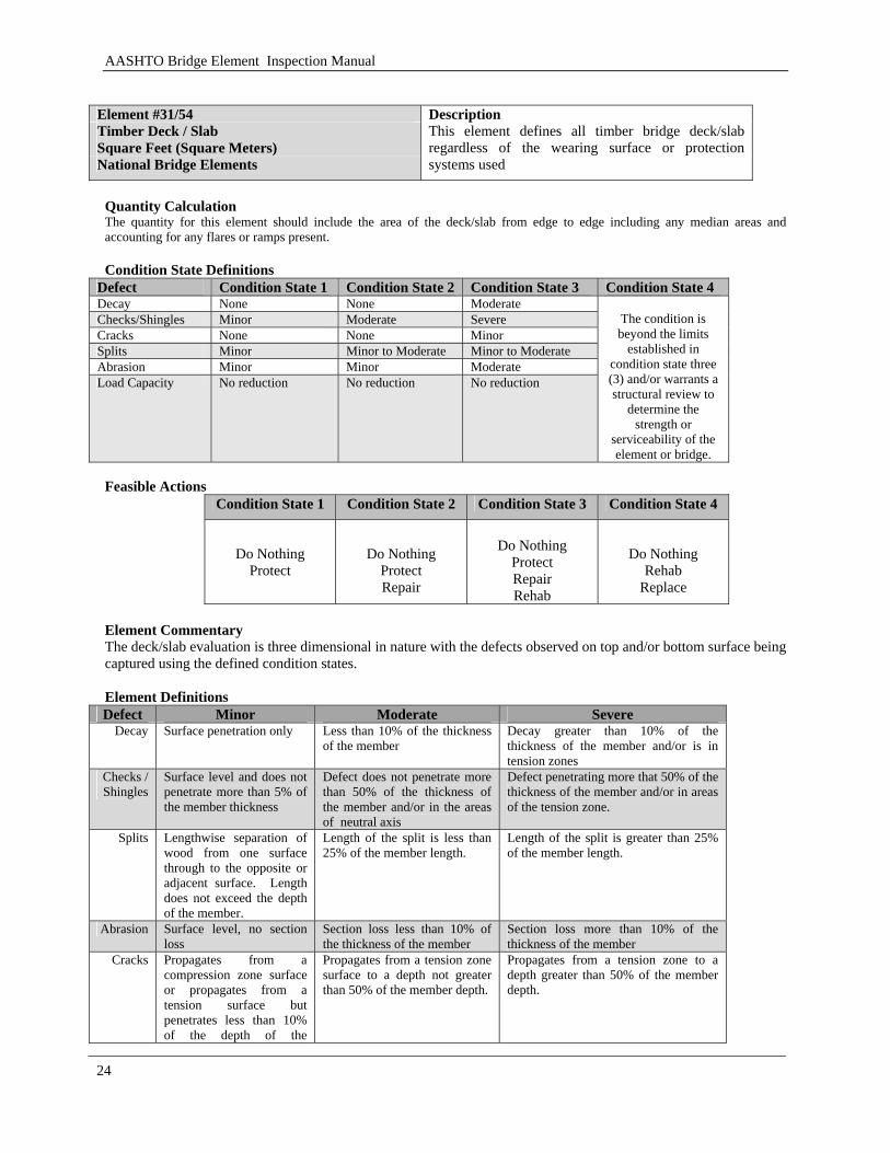
Element #31/54 Timber Deck / Slab Square Feet (Square Meters) National Bridge Elements
Description This element defines all timber bridge deck/slab regardless of the wearing surface or protection systems used
Quantity Calculation The quantity for this element should include the area of the deck/slab from edge to edge including any median areas and accounting for any flares or ramps present. Condition State Definitions
Defect Condition State 1 Condition State 2 Condition State 3 Condition State 4 Decay None None Moderate Checks/Shingles Minor Moderate Severe Cracks None None Minor Splits Minor Minor to Moderate Minor to Moderate Abrasion Minor Minor Moderate Load Capacity No reduction No reduction No reduction
The condition is beyond the limits
established in condition state three (3) and/or warrants a structural review to
determine the strength or
serviceability of the element or bridge.
Feasible Actions
Condition State 1 Condition State 2 Condition State 3 Condition State 4
Do Nothing
Protect
Do Nothing
Protect Repair
Do Nothing
Protect Repair Rehab
Do Nothing
Rehab Replace
Element Commentary The deck/slab evaluation is three dimensional in nature with the defects observed on top and/or bottom surface being captured using the defined condition states. Element Definitions Defect Minor Moderate Severe
Decay Surface penetration only Less than 10% of the thickness of the member
Decay greater than 10% of the thickness of the member and/or is in tension zones
Checks / Shingles
Surface level and does not penetrate more than 5% of the member thickness
Defect does not penetrate more than 50% of the thickness of the member and/or in the areas of neutral axis
Defect penetrating more that 50% of the thickness of the member and/or in areas of the tension zone.
Splits Lengthwise separation of wood from one surface through to the opposite or adjacent surface. Length does not exceed the depth of the member.
Length of the split is less than 25% of the member length.
Length of the split is greater than 25% of the member length.
Abrasion Surface level, no section loss
Section loss less than 10% of the thickness of the member
Section loss more than 10% of the thickness of the member
Cracks Propagates from a compression zone surface or propagates from a tension surface but penetrates less than 10% of the depth of the
Propagates from a tension zone surface to a depth not greater than 50% of the member depth.
Propagates from a tension zone to a depth greater than 50% of the member depth.
AASHTO Bridge Element Inspection Manual
25
member.
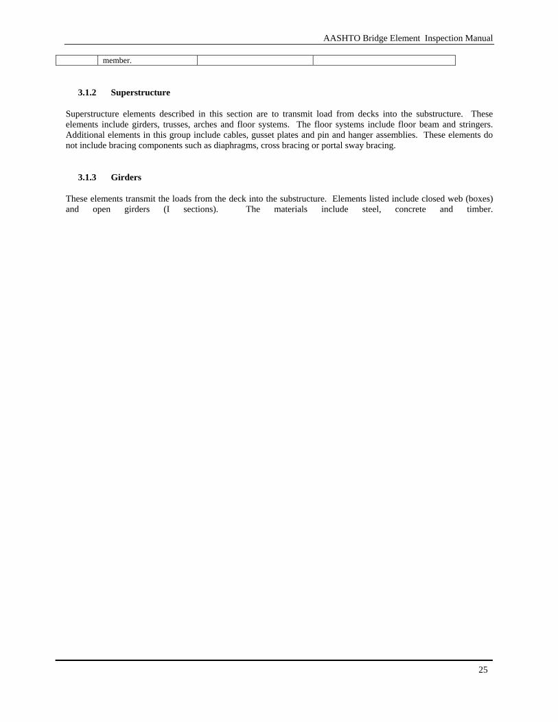
3.1.2 Superstructure
Superstructure elements described in this section are to transmit load from decks into the substructure. These elements include girders, trusses, arches and floor systems. The floor systems include floor beam and stringers. Additional elements in this group include cables, gusset plates and pin and hanger assemblies. These elements do not include bracing components such as diaphragms, cross bracing or portal sway bracing.
3.1.3 Girders
These elements transmit the loads from the deck into the substructure. Elements listed include closed web (boxes) and open girders (I sections). The materials include steel, concrete and timber.

AASHTO Bridge Element Inspection Manual
26
[BLANK PAGE]
AASHTO Bridge Element Inspection Manual
27
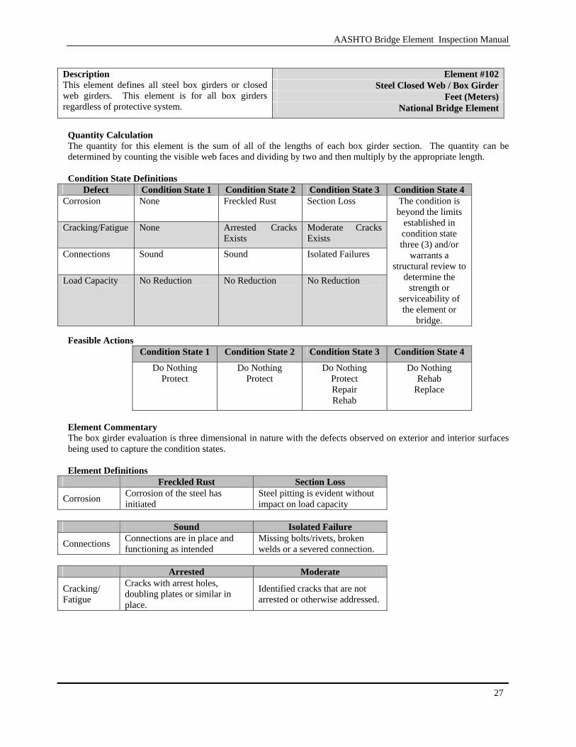
Element #102
Steel Closed Web / Box Girder Feet (Meters)
Description This element defines all steel box girders or closed web girders. This element is for all box girders regardless of protective system. National Bridge Element
Quantity Calculation The quantity for this element is the sum of all of the lengths of each box girder section. The quantity can be determined by counting the visible web faces and dividing by two and then multiply by the appropriate length. Condition State Definitions
Defect Condition State 1 Condition State 2 Condition State 3 Condition State 4 Corrosion None Freckled Rust Section Loss
Cracking/Fatigue None Arrested Cracks Exists
Moderate Cracks Exists
Connections Sound Sound Isolated Failures
Load Capacity No Reduction No Reduction No Reduction
The condition is beyond the limits
established in condition state three (3) and/or
warrants a structural review to
determine the strength or
serviceability of the element or
bridge. Feasible Actions
Condition State 1 Condition State 2 Condition State 3 Condition State 4
Do Nothing Protect
Do Nothing Protect
Do Nothing Protect Repair Rehab
Do Nothing Rehab
Replace
Element Commentary The box girder evaluation is three dimensional in nature with the defects observed on exterior and interior surfaces being used to capture the condition states. Element Definitions
Freckled Rust Section Loss
Corrosion Corrosion of the steel has initiated
Steel pitting is evident without impact on load capacity
Sound Isolated Failure
Connections Connections are in place and functioning as intended
Missing bolts/rivets, broken welds or a severed connection.
Arrested Moderate
Cracking/ Fatigue
Cracks with arrest holes, doubling plates or similar in place.
Identified cracks that are not arrested or otherwise addressed.

AASHTO Bridge Element Inspection Manual
28
Element #104 Prestressed Concrete Closed Web / Box Girder Feet (Meters) National Bridge Elements
Description This element defines pre-tensioned or post tensioned concrete closed web girder or box girder. This element is for all box girders regardless of protective system.
Quantity Calculation The quantity for this element is the sum of all of the lengths of each girder. The quantity can be determined by counting the visible web faces and dividing by two and then multiply by the appropriate length. Condition State Definitions
Defect Condition State 1 Condition State 2 Condition State 3 Condition State 4 Spalls/ Delaminations/ Patch Areas
None Moderate spall or patch areas that are sound
Severe spall or patched area showing distress
Exposed Rebar None None Corrosion without section loss
Exposed Prestressing None None Present with no
section loss
Cracks Hairline Cracks Only
Narrow size or density
Medium size or density
Efflorescence None Moderate but without rust
Severe with rust staining
Load Capacity No Reduction No Reduction No Reduction
The condition is beyond the limits
established in condition state three (3) and/or
warrants a structural review to
determine the strength or
serviceability of the element or
bridge. Feasible Actions
Condition State 1 Condition State 2 Condition State 3 Condition State 4 Do Nothing
Protect Do Nothing
Protect Do Nothing
Protect Repair Rehab
Do Nothing Rehab
Replace
Element Commentary The box girder evaluation is three dimensional in nature which includes defect observed on exterior and interior surfaces. If the riding surface is the exposed top surface, evaluation of the riding surface above the filet should be considered with element 15. Element Definitions
Defect Hairline - Minor Narrow-Moderate Medium-Severe
Cracking < 0.004 inches (0.1 mm)
0.004 – 0.009 inches (0.1 – 0.23 mm)
>0.009 inches (0.23 mm)
Cracking Density NA 1.0 - 3.0 feet apart
(0.33 – 1.0 m) < 1 foot (0.33 m)
Efflorescence NA Surface white without build-up or leaching
Heavy build-up with rust staining
Spalls/ Delaminations N/A
Spall less than 1 inch (25 mm) deep or less than 6 inches in diameter
Spall greater than 1 inch (25 mm) deep or greater than 6 inches in diameter or exposed rebar

AASHTO Bridge Element Inspection Manual
29
Element #105
Reinforced Concrete Closed Web / Box Girder Feet (Meters)
Description This element defines a reinforced concrete box girder or closed web girder. This element is for all box girders regardless of the protective system National Bridge Element
Quantity Calculation The quantity for this element is the sum of all the lengths of each girder. The quantity can be determined by counting the visible web faces and dividing by two and then multiply by the appropriate length. Condition State Definitions
Defect Condition State 1 Condition State 2 Condition State 3 Condition State 4
Cracking None to hairline Narrow size and/or density
Medium size and/or density
Spalls / Delaminations/ Patched Areas
None Moderate spall or patch areas that are sound
Severe spall or patched area showing distress
Efflorescence None Moderate without rust
Severe with rust staining
Load Capacity No reduction No reduction No reduction
The condition is beyond the limits
established in condition state three (3) and/or
warrants a structural review to
determine the strength or
serviceability of the element or
bridge. Feasible Actions
Condition State 1 Condition State 2 Condition State 3 Condition State 4 Do Nothing
Protect Do Nothing
Protect Do Nothing
Protect Repair Rehab
Do Nothing Rehab
Replace
Element Commentary The box girder evaluation is three dimensional in nature with the defects observed include exterior and interior surfaces being used to capture the condition states. If the riding surface is the exposed top surface, evaluation of the riding surface above the filet should be considered with element 15. Element Definitions
Defect Hairline - Minor Narrow-Moderate Medium-Severe
Cracking < 0.0625 inches (1.6 mm)
0.0625 – 0.125 inches (1.6 – 3.2 mm)
>0.125 inches (3.2 mm)
Spalls/ Delaminations N/A
Spall less than 1 inch (25 mm) deep or less than 6 inches in diameter
Spall greater than 1 inch (25 mm) deep or greater than 6 inches in diameter or exposed rebar
Cracking Density Spacing Greater than 3.0 feet (0.33 m)
Spacing of 1.0 - 3.0 feet (0.33 – 1.0 m)
Spacing of less than 1 foot (0.33 m)
Efflorescence NA Surface white without build-up or leaching
Heavy build-up with rust staining
AASHTO Bridge Element Inspection Manual
30
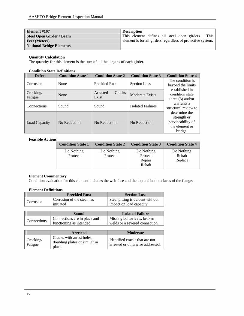
Element #107 Steel Open Girder / Beam Feet (Meters) National Bridge Elements
Description This element defines all steel open girders. This element is for all girders regardless of protective system.
Quantity Calculation The quantity for this element is the sum of all the lengths of each girder. Condition State Definitions
Defect Condition State 1 Condition State 2 Condition State 3 Condition State 4
Corrosion None Freckled Rust Section Loss
Cracking/ Fatigue None Arrested Cracks
Exist Moderate Exists
Connections Sound Sound Isolated Failures
Load Capacity No Reduction No Reduction No Reduction
The condition is beyond the limits
established in condition state three (3) and/or
warrants a structural review to
determine the strength or
serviceability of the element or
bridge. Feasible Actions
Condition State 1 Condition State 2 Condition State 3 Condition State 4 Do Nothing
Protect Do Nothing
Protect Do Nothing
Protect Repair Rehab
Do Nothing Rehab
Replace
Element Commentary Condition evaluation for this element includes the web face and the top and bottom faces of the flange. Element Definitions
Freckled Rust Section Loss
Corrosion Corrosion of the steel has initiated
Steel pitting is evident without impact on load capacity
Sound Isolated Failure
Connections Connections are in place and functioning as intended
Missing bolts/rivets, broken welds or a severed connection.
Arrested Moderate
Cracking/ Fatigue
Cracks with arrest holes, doubling plates or similar in place.
Identified cracks that are not arrested or otherwise addressed.
AASHTO Bridge Element Inspection Manual
31
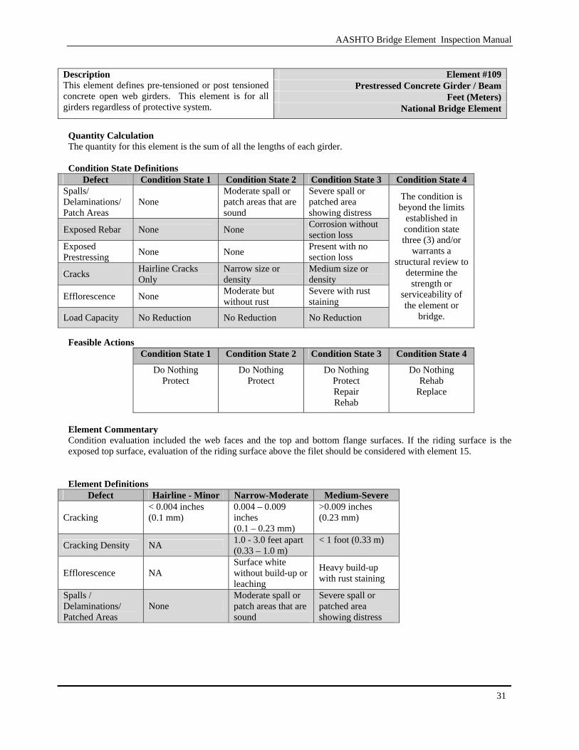
Element #109
Prestressed Concrete Girder / Beam Feet (Meters)
Description This element defines pre-tensioned or post tensioned concrete open web girders. This element is for all girders regardless of protective system. National Bridge Element
Quantity Calculation The quantity for this element is the sum of all the lengths of each girder. Condition State Definitions
Defect Condition State 1 Condition State 2 Condition State 3 Condition State 4 Spalls/ Delaminations/ Patch Areas
None Moderate spall or patch areas that are sound
Severe spall or patched area showing distress
Exposed Rebar None None Corrosion without section loss
Exposed Prestressing None None Present with no
section loss
Cracks Hairline Cracks Only
Narrow size or density
Medium size or density
Efflorescence None Moderate but without rust
Severe with rust staining
Load Capacity No Reduction No Reduction No Reduction
The condition is beyond the limits
established in condition state three (3) and/or
warrants a structural review to
determine the strength or
serviceability of the element or
bridge.
Feasible Actions
Condition State 1 Condition State 2 Condition State 3 Condition State 4
Do Nothing Protect
Do Nothing Protect
Do Nothing Protect Repair Rehab
Do Nothing Rehab
Replace
Element Commentary Condition evaluation included the web faces and the top and bottom flange surfaces. If the riding surface is the exposed top surface, evaluation of the riding surface above the filet should be considered with element 15. Element Definitions
Defect Hairline - Minor Narrow-Moderate Medium-Severe
Cracking < 0.004 inches (0.1 mm)
0.004 – 0.009 inches (0.1 – 0.23 mm)
>0.009 inches (0.23 mm)
Cracking Density NA 1.0 - 3.0 feet apart (0.33 – 1.0 m)
< 1 foot (0.33 m)
Efflorescence NA Surface white without build-up or leaching
Heavy build-up with rust staining
Spalls / Delaminations/ Patched Areas
None Moderate spall or patch areas that are sound
Severe spall or patched area showing distress

AASHTO Bridge Element Inspection Manual
32
Element #110 Reinforced Concrete Girder / Beam Feet (Meters) National Bridge Element
Description This element defines mild steel reinforced concrete open web girders. This element is for all girders regardless of protective system.
Quantity Calculation The quantity for this element is the sum of all of the lengths of each girder. Condition State Definitions
Defect Condition State 1 Condition State 2 Condition State 3 Condition State 4
Cracking None to hairline Narrow size and/or density
Medium size and/or density
Spalls / Delaminations/ Patched Areas
None Moderate spall or patch areas that are sound
Severe spall or patched area showing distress
Efflorescence None Moderate without rust
Severe with rust staining
Load Capacity No reduction No reduction No reduction
The condition is beyond the limits
established in condition state three (3) and/or
warrants a structural review to
determine the strength or
serviceability of the element or
bridge. Feasible Actions
Condition State 1 Condition State 2 Condition State 3 Condition State 4
Do Nothing Protect
Do Nothing Protect
Do Nothing Protect Repair Rehab
Do Nothing Rehab
Replace
Element Commentary If the riding surface is the exposed top surface, evaluation of the riding surface above the filet should be considered with element 15. Element Definitions
Defect Hairline - Minor Narrow-Moderate Medium-Severe
Cracking < 0.0625 inches (1.6 mm)
0.0625 – 0.125 inches (1.6 – 3.2 mm)
>0.125 inches (3.2 mm)
Spalls/ Delaminations N/A
Spall less than 1 inch (25 mm) deep or less than 6 inches in diameter
Spall greater than 1 inch (25 mm) deep or greater than 6 inches in diameter or exposed rebar
Cracking Density Spacing Greater than 3.0 feet (0.33 m)
Spacing of 1.0 - 3.0 feet (0.33 – 1.0 m)
Spacing of less than 1 foot (0.33 m)
Efflorescence NA Surface white without build-up or leaching
Heavy build-up with rust staining

AASHTO Bridge Element Inspection Manual
33
Element #111
Timber Open Girder Feet (Meters)
Description This element defines all timber girders. This element is for all girders regardless of protection system.
National Bridge Element
Quantity Calculation The quantity for this element is the sum of all the lengths of each girder. Condition State Definitions
Defect Condition State 1 Condition State 2 Condition State 3 Condition State 4 Decay None None Moderate Checks/Shingles Minor Moderate Severe Cracks None None Minor Splits Minor Minor to Moderate Minor to Moderate Abrasion Minor Minor Moderate Load Capacity No reduction No reduction No reduction
The condition is beyond the limits
established in condition state three (3) and/or warrants a structural review to
determine the strength or
serviceability of the element or bridge.
Feasible Actions
Condition State 1 Condition State 2 Condition State 3 Condition State 4
Do Nothing Protect
Do Nothing Protect Repair
Do Nothing Protect Repair Rehab
Do Nothing
Rehab Replace
Element Commentary None Element Definitions Defect Minor Moderate Severe
Decay Surface penetration only Less than 10% of the thickness of the member
Decay greater than 10% of the thickness of the member and/or is in tension zones
Checks / Shingles
Surface level and does not penetrate more than 5% of the member thickness
Defect does not penetrate more than 50% of the thickness of the member and/or in the areas of neutral axis
Defect penetrating more that 50% of the thickness of the member and/or in areas of the tension zone.
Splits Lengthwise separation of wood from one surface through to the opposite or adjacent surface. Length does not exceed the depth of the member.
Length of the split is less than 25% of the member length.
Length of the split is greater than 25% of the member length.
Abrasion Surface level, no section loss
Section loss no less than 10% of the thickness of the member
Section loss more than 10% of the thickness of the member
Cracks Propagates from a compression zone surface or propagates from a tension surface but penetrates less than 10% of the depth of the member.
Propagates from a tension zone surface to a depth not greater than 50% of the member depth.
Propagates from a tension zone to a depth greater than 50% of the member depth.
AASHTO Bridge Element Inspection Manual
34
3.1.4 Stringers
These elements are a part of a floor system. These superstructure elements transmit load from the deck into the floor system such as floor beams.
AASHTO Bridge Element Inspection Manual
35
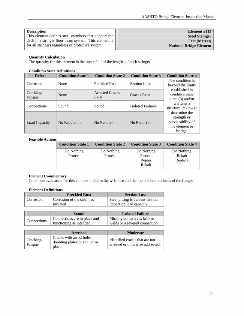
Element #113 Steel Stringer Feet (Meters)
Description This element defines steel members that support the deck in a stringer floor beam system. This element is for all stringers regardless of protective system. National Bridge Element
Quantity Calculation The quantity for this element is the sum of all of the lengths of each stringer. Condition State Definitions
Defect Condition State 1 Condition State 2 Condition State 3 Condition State 4
Corrosion None Freckled Rust Section Loss
Cracking/ Fatigue None Arrested Cracks
Exist Cracks Exist
Connections Sound Sound Isolated Failures
Load Capacity No Reduction No Reduction No Reduction
The condition is beyond the limits
established in condition state three (3) and/or
warrants a structural review to
determine the strength or
serviceability of the element or
bridge. Feasible Actions
Condition State 1 Condition State 2 Condition State 3 Condition State 4 Do Nothing
Protect Do Nothing
Protect Do Nothing
Protect Repair Rehab
Do Nothing Rehab
Replace
Element Commentary Condition evaluation for this element includes the web face and the top and bottom faces of the flange. Element Definitions
Freckled Rust Section Loss Corrosion Corrosion of the steel has
initiated Steel pitting is evident without impact on load capacity
Sound Isolated Failure
Connections Connections are in place and functioning as intended
Missing bolts/rivets, broken welds or a severed connection.
Arrested Moderate
Cracking/ Fatigue
Cracks with arrest holes, doubling plates or similar in place.
Identified cracks that are not arrested or otherwise addressed.
AASHTO Bridge Element Inspection Manual
36
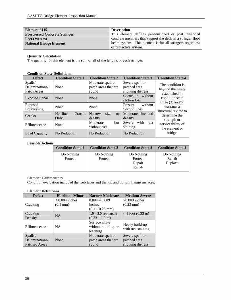
Element #115 Prestressed Concrete Stringer Feet (Meters) National Bridge Element
Description This element defines pre-tensioned or post tensioned concrete members that support the deck in a stringer floor beam system. This element is for all stringers regardless of protective system.
Quantity Calculation The quantity for this element is the sum of all of the lengths of each stringer. Condition State Definitions
Defect Condition State 1 Condition State 2 Condition State 3 Condition State 4 Spalls/ Delaminations/ Patch Areas
None Moderate spall or patch areas that are sound
Severe spall or patched area showing distress
Exposed Rebar None None Corrosion without section loss
Exposed Prestressing None None Present without
Section Loss
Cracks Hairline Cracks Only
Narrow size or density
Moderate size and density
Efflorescence None Moderate but without rust
Severe with rust staining
Load Capacity No Reduction No Reduction No Reduction
The condition is beyond the limits
established in condition state three (3) and/or
warrants a structural review to
determine the strength or
serviceability of the element or
bridge.
Feasible Actions
Condition State 1 Condition State 2 Condition State 3 Condition State 4
Do Nothing Protect
Do Nothing Protect
Do Nothing Protect Repair Rehab
Do Nothing Rehab
Replace
Element Commentary Condition evaluation included the web faces and the top and bottom flange surfaces. Element Definitions
Defect Hairline - Minor Narrow-Moderate Medium-Severe
Cracking < 0.004 inches (0.1 mm)
0.004 – 0.009 inches (0.1 – 0.23 mm)
>0.009 inches (0.23 mm)
Cracking Density NA 1.0 - 3.0 feet apart
(0.33 – 1.0 m) < 1 foot (0.33 m)
Efflorescence NA Surface white without build-up or leaching
Heavy build-up with rust staining
Spalls / Delaminations/ Patched Areas
None Moderate spall or patch areas that are sound
Severe spall or patched area showing distress

AASHTO Bridge Element Inspection Manual
37
Element #116
Reinforced Concrete Stringer Feet (Meters)
Description This element defines mild steel reinforced concrete members that support the deck in a stringer floor beam system. This element is for all stringers regardless of protective system.
National Bridge Element
Quantity Calculation The quantity for this element is the sum of all of the lengths of each stringer. Condition State Definitions
Defect Condition State 1 Condition State 2 Condition State 3 Condition State 4
Cracking None to hairline Narrow size and/or density
Medium size and/or density
Spalls / Delaminations/ Patched Areas
None Moderate spall or patch areas that are sound
Severe spall or patched area showing distress
Efflorescence None Moderate without rust
Severe with rust staining
Load Capacity No reduction No reduction No reduction
The condition is beyond the limits
established in condition state three (3) and/or
warrants a structural review to
determine the strength or
serviceability of the element or
bridge. Feasible Actions
Condition State 1 Condition State 2 Condition State 3 Condition State 4 Do Nothing
Protect Do Nothing
Protect Do Nothing
Protect Repair Rehab
Do Nothing Rehab
Replace
Element Commentary None Element Definitions
Defect Hairline - Minor Narrow-Moderate Medium-Severe
Cracking < 0.0625 inches (1.6 mm)
0.0625 – 0.125 inches (1.6 – 3.2 mm)
>0.125 inches (3.2 mm)
Spalls/ Delaminations N/A
Spall less than 1 inch (25 mm) deep or less than 6 inches in diameter
Spall greater than 1 inch (25 mm) deep or greater than 6 inches in diameter or exposed rebar
Cracking Density Spacing Greater than 3.0 feet (0.33 m)
Spacing of 1.0 - 3.0 feet (0.33 – 1.0 m)
Spacing of less than 1 foot (0.33 m)
Efflorescence NA Surface white without build-up or leaching
Heavy build-up with rust staining
AASHTO Bridge Element Inspection Manual
38
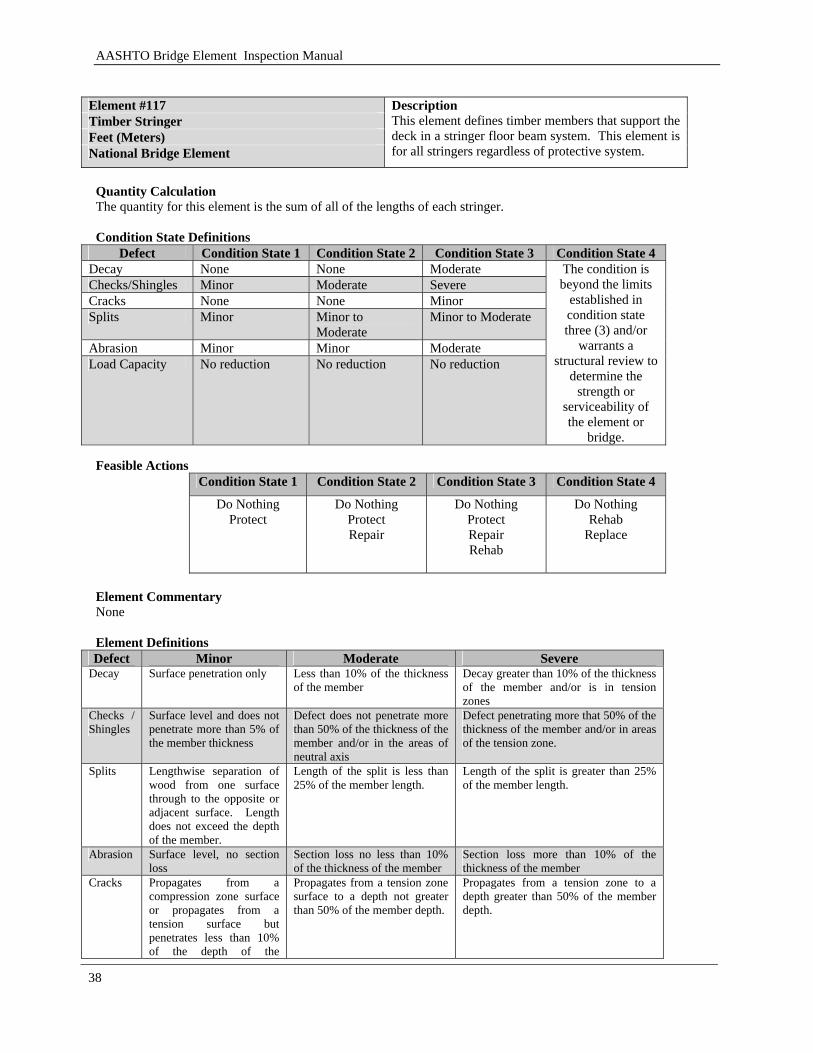
Element #117 Timber Stringer Feet (Meters) National Bridge Element
Description This element defines timber members that support the deck in a stringer floor beam system. This element is for all stringers regardless of protective system.
Quantity Calculation The quantity for this element is the sum of all of the lengths of each stringer. Condition State Definitions
Defect Condition State 1 Condition State 2 Condition State 3 Condition State 4 Decay None None Moderate Checks/Shingles Minor Moderate Severe Cracks None None Minor Splits Minor Minor to
Moderate Minor to Moderate
Abrasion Minor Minor Moderate Load Capacity No reduction No reduction No reduction
The condition is beyond the limits
established in condition state three (3) and/or
warrants a structural review to
determine the strength or
serviceability of the element or
bridge. Feasible Actions
Condition State 1 Condition State 2 Condition State 3 Condition State 4 Do Nothing
Protect
Do Nothing Protect Repair
Do Nothing Protect Repair Rehab
Do Nothing Rehab
Replace
Element Commentary None Element Definitions Defect Minor Moderate Severe
Decay Surface penetration only Less than 10% of the thickness of the member
Decay greater than 10% of the thickness of the member and/or is in tension zones
Checks / Shingles
Surface level and does not penetrate more than 5% of the member thickness
Defect does not penetrate more than 50% of the thickness of the member and/or in the areas of neutral axis
Defect penetrating more that 50% of the thickness of the member and/or in areas of the tension zone.
Splits Lengthwise separation of wood from one surface through to the opposite or adjacent surface. Length does not exceed the depth of the member.
Length of the split is less than 25% of the member length.
Length of the split is greater than 25% of the member length.
Abrasion Surface level, no section loss
Section loss no less than 10% of the thickness of the member
Section loss more than 10% of the thickness of the member
Cracks Propagates from a compression zone surface or propagates from a tension surface but penetrates less than 10% of the depth of the
Propagates from a tension zone surface to a depth not greater than 50% of the member depth.
Propagates from a tension zone to a depth greater than 50% of the member depth.
AASHTO Bridge Element Inspection Manual
39
member.
3.1.5 Trusses / Arches
These elements include materials of steel, concrete, timber and masonry. These superstructure elements are the main load carrying member for the span.

AASHTO Bridge Element Inspection Manual
40
[BLANK PAGE]
AASHTO Bridge Element Inspection Manual
41
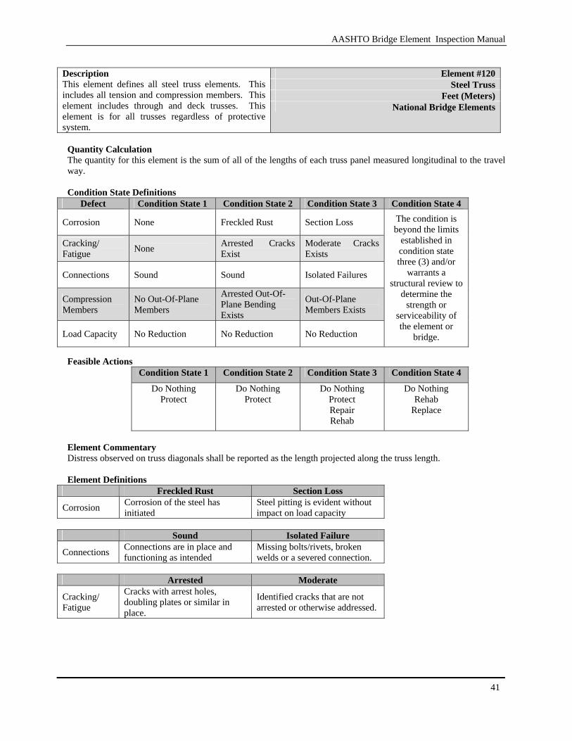
Element #120
Steel Truss Feet (Meters)
Description This element defines all steel truss elements. This includes all tension and compression members. This element includes through and deck trusses. This element is for all trusses regardless of protective system.
National Bridge Elements
Quantity Calculation The quantity for this element is the sum of all of the lengths of each truss panel measured longitudinal to the travel way. Condition State Definitions
Defect Condition State 1 Condition State 2 Condition State 3 Condition State 4
Corrosion None Freckled Rust Section Loss
Cracking/ Fatigue None Arrested Cracks
Exist Moderate Cracks Exists
Connections Sound Sound Isolated Failures
Compression Members
No Out-Of-Plane Members
Arrested Out-Of-Plane Bending Exists
Out-Of-Plane Members Exists
Load Capacity No Reduction No Reduction No Reduction
The condition is beyond the limits
established in condition state three (3) and/or
warrants a structural review to
determine the strength or
serviceability of the element or
bridge. Feasible Actions
Condition State 1 Condition State 2 Condition State 3 Condition State 4 Do Nothing
Protect Do Nothing
Protect Do Nothing
Protect Repair Rehab
Do Nothing Rehab
Replace
Element Commentary Distress observed on truss diagonals shall be reported as the length projected along the truss length. Element Definitions
Freckled Rust Section Loss
Corrosion Corrosion of the steel has initiated
Steel pitting is evident without impact on load capacity
Sound Isolated Failure
Connections Connections are in place and functioning as intended
Missing bolts/rivets, broken welds or a severed connection.
Arrested Moderate
Cracking/ Fatigue
Cracks with arrest holes, doubling plates or similar in place.
Identified cracks that are not arrested or otherwise addressed.
AASHTO Bridge Element Inspection Manual
42
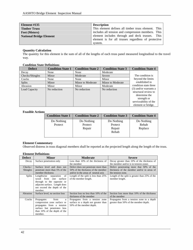
Element #135 Timber Truss Feet (Meters) National Bridge Element
Description This element defines all timber truss element. This includes all tension and compression members. This element includes through and deck trusses. This element is for all trusses regardless of protective system.
Quantity Calculation The quantity for this element is the sum of all of the lengths of each truss panel measured longitudinal to the travel way. Condition State Definitions
Defect Condition State 1 Condition State 2 Condition State 3 Condition State 4 Decay None None Moderate Checks/Shingles Minor Moderate Severe Cracks None None Minor Splits Minor Minor to Moderate Minor to Moderate Abrasion Minor Minor Moderate Load Capacity No reduction No reduction No reduction
The condition is beyond the limits
established in condition state three (3) and/or warrants a structural review to
determine the strength or
serviceability of the element or bridge.
Feasible Actions
Condition State 1 Condition State 2 Condition State 3 Condition State 4
Do Nothing Protect
Do Nothing Protect Repair
Do Nothing Protect Repair Rehab
Do Nothing Rehab
Replace
Element Commentary Observed distress in truss diagonal members shall be reported as the projected length along the length of the truss. Element Definitions Defect Minor Moderate Severe
Decay Surface penetration only Less than 10% of the thickness of the member
Decay greater than 10% of the thickness of the member and/or is in tension zones
Checks / Shingles
Surface level and does not penetrate more than 5% of the member thickness
Defect does not penetrate more than 50% of the thickness of the member and/or in the areas of neutral axis
Defect penetrating more that 50% of the thickness of the member and/or in areas of the tension zone.
Splits Lengthwise separation of wood from one surface through to the opposite or adjacent surface. Length does not exceed the depth of the member.
Length of the split is less than 25% of the member length.
Length of the split is greater than 25% of the member length.
Abrasion Surface level, no section loss Section loss no less than 10% of the thickness of the member
Section loss more than 10% of the thickness of the member
Cracks Propagates from a compression zone surface or propagates from a tension surface but penetrates less than 10% of the depth of the member.
Propagates from a tension zone surface to a depth not greater than 50% of the member depth.
Propagates from a tension zone to a depth greater than 50% of the member depth.
AASHTO Bridge Element Inspection Manual
43
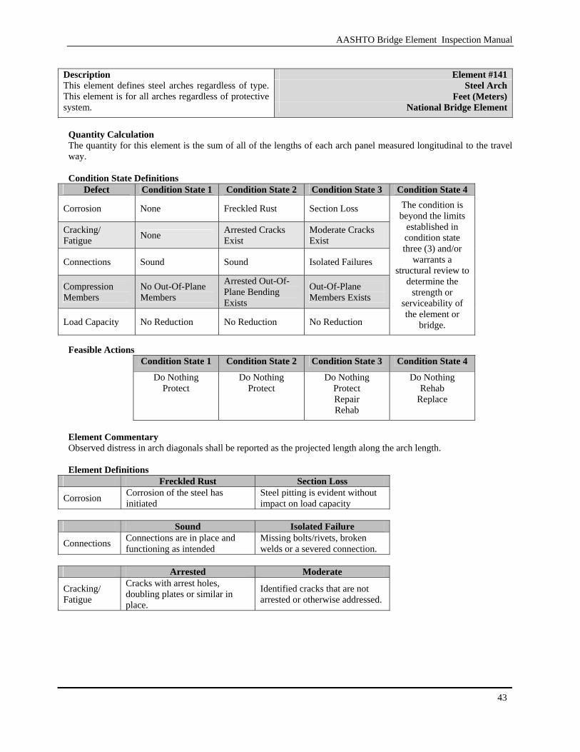
Element #141
Steel Arch Feet (Meters)
Description This element defines steel arches regardless of type. This element is for all arches regardless of protective system. National Bridge Element
Quantity Calculation The quantity for this element is the sum of all of the lengths of each arch panel measured longitudinal to the travel way. Condition State Definitions
Defect Condition State 1 Condition State 2 Condition State 3 Condition State 4
Corrosion None Freckled Rust Section Loss
Cracking/ Fatigue None Arrested Cracks
Exist Moderate Cracks Exist
Connections Sound Sound Isolated Failures
Compression Members
No Out-Of-Plane Members
Arrested Out-Of-Plane Bending Exists
Out-Of-Plane Members Exists
Load Capacity No Reduction No Reduction No Reduction
The condition is beyond the limits
established in condition state three (3) and/or
warrants a structural review to
determine the strength or
serviceability of the element or
bridge. Feasible Actions
Condition State 1 Condition State 2 Condition State 3 Condition State 4
Do Nothing Protect
Do Nothing Protect
Do Nothing Protect Repair Rehab
Do Nothing Rehab
Replace
Element Commentary Observed distress in arch diagonals shall be reported as the projected length along the arch length. Element Definitions
Freckled Rust Section Loss
Corrosion Corrosion of the steel has initiated
Steel pitting is evident without impact on load capacity
Sound Isolated Failure
Connections Connections are in place and functioning as intended
Missing bolts/rivets, broken welds or a severed connection.
Arrested Moderate
Cracking/ Fatigue
Cracks with arrest holes, doubling plates or similar in place.
Identified cracks that are not arrested or otherwise addressed.

AASHTO Bridge Element Inspection Manual
44
Element #143 Prestressed Concrete Arch Feet (Meters) National Bridge Element
Description This element defines only pre-tensioned or post tensioned concrete arches. This element is for all arches regardless of protective system.
Quantity Calculation The quantity for this element is the sum of the length of each arch panel measured longitudinal to the travel way. Condition State Definitions
Defect Condition State 1 Condition State 2 Condition State 3 Condition State 4 Spalls/ Delaminations/ Patch Areas
None Moderate spall or patch areas that are sound
Severe spall or patched area showing distress
Exposed Rebar None None Corrosion without section loss
Exposed Prestressing None None Present with no
section loss
Cracks Hairline Cracks Only
Narrow size or density
Medium size or density
Efflorescence None Moderate but without rust
Severe with rust staining
Load Capacity No Reduction No Reduction No Reduction
The condition is beyond the limits
established in condition state three (3) and/or
warrants a structural review to
determine the strength or
serviceability of the element or
bridge.
Feasible Actions
Condition State 1 Condition State 2 Condition State 3 Condition State 4
Do Nothing Protect
Do Nothing Protect
Do Nothing Protect Repair Rehab
Do Nothing Rehab
Replace
Element Commentary None Element Definitions
Defect Hairline - Minor Narrow-Moderate Medium-Severe
Cracking < 0.004 inches (0.1 mm)
0.004 – 0.009 inches (0.1 – 0.23 mm)
>0.009 inches (0.23 mm)
Cracking Density NA 1.0 - 3.0 feet apart
(0.33 – 1.0 m) < 1 foot (0.33 m)
Efflorescence NA Surface white without build-up or leaching
Heavy build-up with rust staining
Spalls/ Delaminations N/A
Spall less than 1 inch (25 mm) deep or less than 6 inches in diameter
Spall greater than 1 inch (25 mm) deep or greater than 6 inches in diameter or exposed rebar
AASHTO Bridge Element Inspection Manual
45
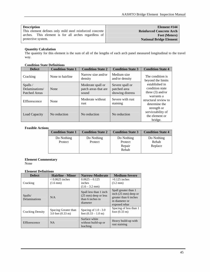
Element #144
Reinforced Concrete Arch Feet (Meters)
Description This element defines only mild steel reinforced concrete arches. This element is for all arches regardless of protective system. National Bridge Element
Quantity Calculation The quantity for this element is the sum of all of the lengths of each arch panel measured longitudinal to the travel way. Condition State Definitions
Defect Condition State 1 Condition State 2 Condition State 3 Condition State 4
Cracking None to hairline Narrow size and/or density
Medium size and/or density
Spalls / Delaminations/ Patched Areas
None Moderate spall or patch areas that are sound
Severe spall or patched area showing distress
Efflorescence None Moderate without rust
Severe with rust staining
Load Capacity No reduction No reduction No reduction
The condition is beyond the limits
established in condition state three (3) and/or
warrants a structural review to
determine the strength or
serviceability of the element or
bridge. Feasible Actions
Condition State 1 Condition State 2 Condition State 3 Condition State 4
Do Nothing Protect
Do Nothing Protect
Do Nothing Protect Repair Rehab
Do Nothing Rehab
Replace
Element Commentary None Element Definitions
Defect Hairline - Minor Narrow-Moderate Medium-Severe
Cracking < 0.0625 inches (1.6 mm)
0.0625 – 0.125 inches (1.6 – 3.2 mm)
>0.125 inches (3.2 mm)
Spalls/ Delaminations N/A
Spall less than 1 inch (25 mm) deep or less than 6 inches in diameter
Spall greater than 1 inch (25 mm) deep or greater than 6 inches in diameter or exposed rebar
Cracking Density Spacing Greater than 3.0 feet (0.33 m)
Spacing of 1.0 - 3.0 feet (0.33 – 1.0 m)
Spacing of less than 1 foot (0.33 m)
Efflorescence NA Surface white without build-up or leaching
Heavy build-up with rust staining
AASHTO Bridge Element Inspection Manual
46
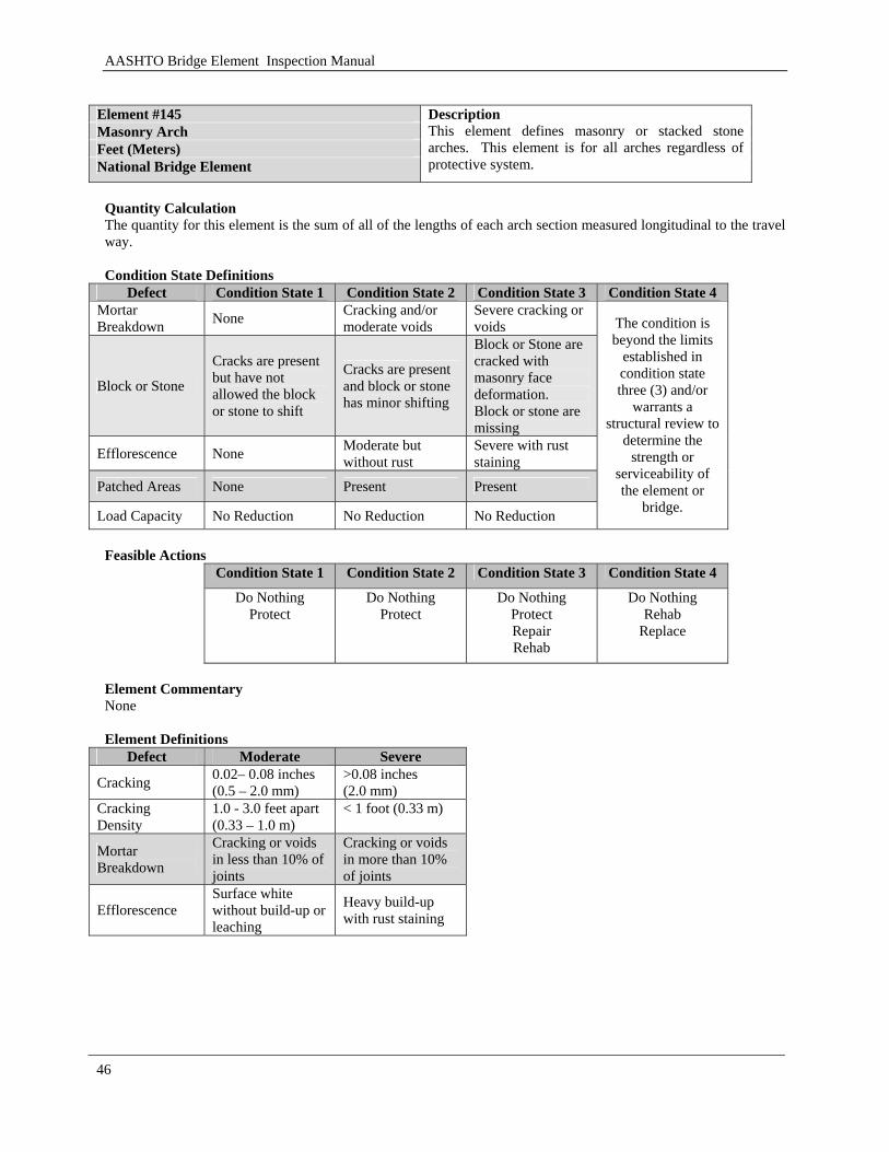
Element #145 Masonry Arch Feet (Meters) National Bridge Element
Description This element defines masonry or stacked stone arches. This element is for all arches regardless of protective system.
Quantity Calculation The quantity for this element is the sum of all of the lengths of each arch section measured longitudinal to the travel way. Condition State Definitions
Defect Condition State 1 Condition State 2 Condition State 3 Condition State 4 Mortar Breakdown None Cracking and/or
moderate voids Severe cracking or voids
Block or Stone
Cracks are present but have not allowed the block or stone to shift
Cracks are present and block or stone has minor shifting
Block or Stone are cracked with masonry face deformation. Block or stone are missing
Efflorescence None Moderate but without rust
Severe with rust staining
Patched Areas None Present Present
Load Capacity No Reduction No Reduction No Reduction
The condition is beyond the limits
established in condition state three (3) and/or
warrants a structural review to
determine the strength or
serviceability of the element or
bridge.
Feasible Actions
Condition State 1 Condition State 2 Condition State 3 Condition State 4
Do Nothing Protect
Do Nothing Protect
Do Nothing Protect Repair Rehab
Do Nothing Rehab
Replace
Element Commentary None Element Definitions
Defect Moderate Severe
Cracking 0.02– 0.08 inches (0.5 – 2.0 mm)
>0.08 inches (2.0 mm)
Cracking Density
1.0 - 3.0 feet apart (0.33 – 1.0 m)
< 1 foot (0.33 m)
Mortar Breakdown
Cracking or voids in less than 10% of joints
Cracking or voids in more than 10% of joints
Efflorescence Surface white without build-up or leaching
Heavy build-up with rust staining
AASHTO Bridge Element Inspection Manual
47
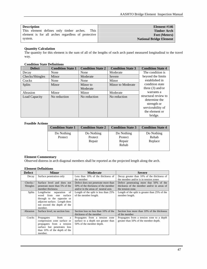
Element #146 Timber Arch Feet (Meters)
Description This element defines only timber arches. This element is for all arches regardless of protective system. National Bridge Element
Quantity Calculation The quantity for this element is the sum of all of the lengths of each arch panel measured longitudinal to the travel way. Condition State Definitions
Defect Condition State 1 Condition State 2 Condition State 3 Condition State 4 Decay None None Moderate Checks/Shingles Minor Moderate Severe Cracks None None Minor Splits Minor Minor to
Moderate Minor to Moderate
Abrasion Minor Minor Moderate Load Capacity No reduction No reduction No reduction
The condition is beyond the limits
established in condition state three (3) and/or
warrants a structural review to
determine the strength or
serviceability of the element or
bridge. Feasible Actions
Condition State 1 Condition State 2 Condition State 3 Condition State 4
Do Nothing Protect
Do Nothing Protect Repair
Do Nothing Protect Repair Rehab
Do Nothing Rehab
Replace
Element Commentary Observed distress in arch diagonal members shall be reported as the projected length along the arch. Element Definitions Defect Minor Moderate Severe
Decay Surface penetration only Less than 10% of the thickness of the member
Decay greater than 10% of the thickness of the member and/or is in tension zones
Checks / Shingles
Surface level and does not penetrate more than 5% of the member thickness
Defect does not penetrate more than 50% of the thickness of the member and/or in the areas of neutral axis
Defect penetrating more that 50% of the thickness of the member and/or in areas of the tension zone.
Splits Lengthwise separation of wood from one surface through to the opposite or adjacent surface. Length does not exceed the depth of the member.
Length of the split is less than 25% of the member length.
Length of the split is greater than 25% of the member length.
Abrasion Surface level, no section loss Section loss no less than 10% of the thickness of the member
Section loss more than 10% of the thickness of the member
Cracks Propagates from a compression zone surface or propagates from a tension surface but penetrates less than 10% of the depth of the member.
Propagates from a tension zone surface to a depth not greater than 50% of the member depth.
Propagates from a tension zone to a depth greater than 50% of the member depth.

AASHTO Bridge Element Inspection Manual
48
[BLANK PAGE]
AASHTO Bridge Element Inspection Manual
49
3.1.6 Floor Beams
The elements are the intermediate transverse load carrying members. These elements can be constructed from steel, concrete and timber.

AASHTO Bridge Element Inspection Manual
50
[BLANK PAGE]
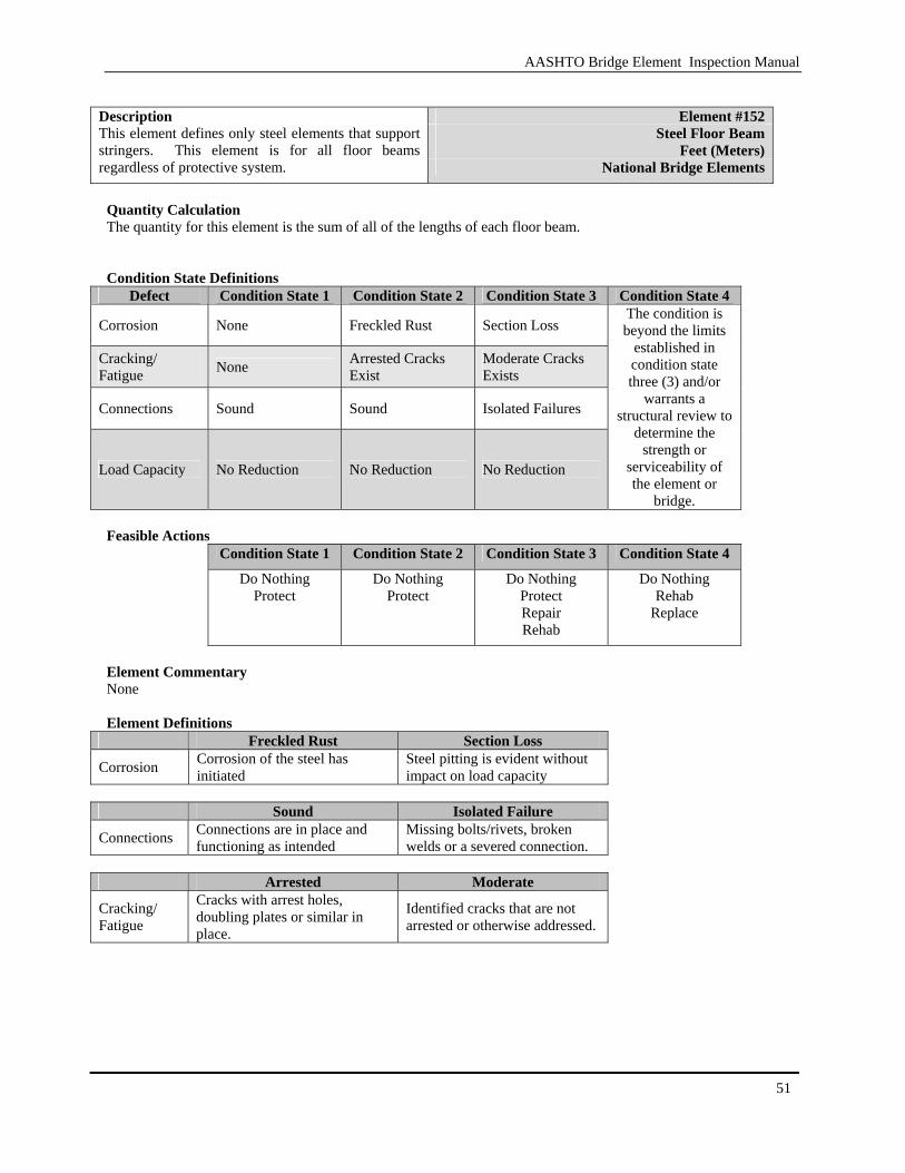
AASHTO Bridge Element Inspection Manual
51
Element #152
Steel Floor Beam Feet (Meters)
Description This element defines only steel elements that support stringers. This element is for all floor beams regardless of protective system. National Bridge Elements
Quantity Calculation The quantity for this element is the sum of all of the lengths of each floor beam. Condition State Definitions
Defect Condition State 1 Condition State 2 Condition State 3 Condition State 4
Corrosion None Freckled Rust Section Loss
Cracking/ Fatigue None Arrested Cracks
Exist Moderate Cracks Exists
Connections Sound Sound Isolated Failures
Load Capacity No Reduction No Reduction No Reduction
The condition is beyond the limits
established in condition state three (3) and/or
warrants a structural review to
determine the strength or
serviceability of the element or
bridge. Feasible Actions
Condition State 1 Condition State 2 Condition State 3 Condition State 4
Do Nothing Protect
Do Nothing Protect
Do Nothing Protect Repair Rehab
Do Nothing Rehab
Replace
Element Commentary None Element Definitions
Freckled Rust Section Loss
Corrosion Corrosion of the steel has initiated
Steel pitting is evident without impact on load capacity
Sound Isolated Failure
Connections Connections are in place and functioning as intended
Missing bolts/rivets, broken welds or a severed connection.
Arrested Moderate
Cracking/ Fatigue
Cracks with arrest holes, doubling plates or similar in place.
Identified cracks that are not arrested or otherwise addressed.
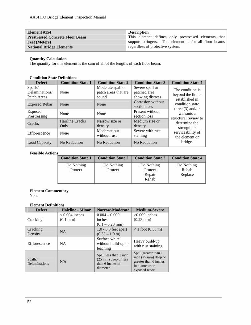
AASHTO Bridge Element Inspection Manual
52
Element #154 Prestressed Concrete Floor Beam Feet (Meters) National Bridge Elements
Description This element defines only prestressed elements that support stringers. This element is for all floor beams regardless of protective system.
Quantity Calculation The quantity for this element is the sum of all of the lengths of each floor beam. Condition State Definitions
Defect Condition State 1 Condition State 2 Condition State 3 Condition State 4 Spalls/ Delaminations/ Patch Areas
None Moderate spall or patch areas that are sound
Severe spall or patched area showing distress
Exposed Rebar None None Corrosion without section loss
Exposed Prestressing None None Present without
section loss
Cracks Hairline Cracks Only
Narrow size or density
Medium size or density
Efflorescence None Moderate but without rust
Severe with rust staining
Load Capacity No Reduction No Reduction No Reduction
The condition is beyond the limits
established in condition state three (3) and/or
warrants a structural review to
determine the strength or
serviceability of the element or
bridge.
Feasible Actions
Condition State 1 Condition State 2 Condition State 3 Condition State 4
Do Nothing Protect
Do Nothing Protect
Do Nothing Protect Repair Rehab
Do Nothing Rehab
Replace
Element Commentary None Element Definitions
Defect Hairline - Minor Narrow-Moderate Medium-Severe
Cracking < 0.004 inches (0.1 mm)
0.004 – 0.009 inches (0.1 – 0.23 mm)
>0.009 inches (0.23 mm)
Cracking Density NA 1.0 - 3.0 feet apart
(0.33 – 1.0 m) < 1 foot (0.33 m)
Efflorescence NA Surface white without build-up or leaching
Heavy build-up with rust staining
Spalls/ Delaminations N/A
Spall less than 1 inch (25 mm) deep or less than 6 inches in diameter
Spall greater than 1 inch (25 mm) deep or greater than 6 inches in diameter or exposed rebar
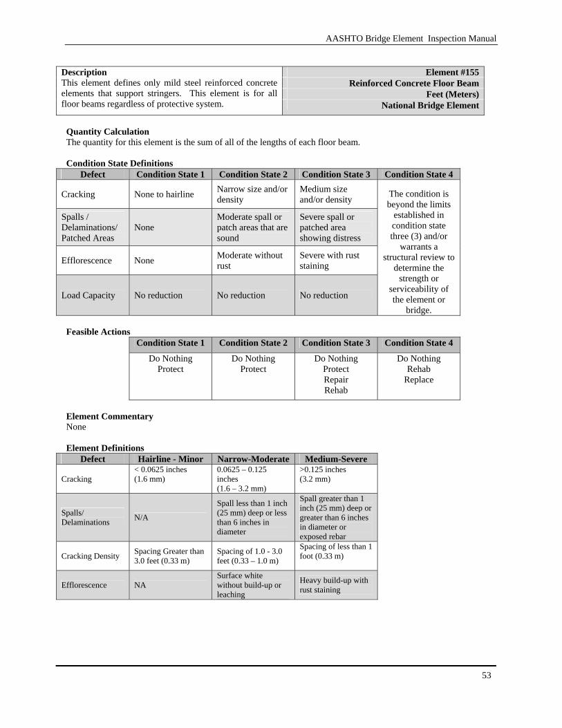
AASHTO Bridge Element Inspection Manual
53
Element #155
Reinforced Concrete Floor Beam Feet (Meters)
Description This element defines only mild steel reinforced concrete elements that support stringers. This element is for all floor beams regardless of protective system. National Bridge Element
Quantity Calculation The quantity for this element is the sum of all of the lengths of each floor beam. Condition State Definitions
Defect Condition State 1 Condition State 2 Condition State 3 Condition State 4
Cracking None to hairline Narrow size and/or density
Medium size and/or density
Spalls / Delaminations/ Patched Areas
None Moderate spall or patch areas that are sound
Severe spall or patched area showing distress
Efflorescence None Moderate without rust
Severe with rust staining
Load Capacity No reduction No reduction No reduction
The condition is beyond the limits
established in condition state three (3) and/or
warrants a structural review to
determine the strength or
serviceability of the element or
bridge. Feasible Actions
Condition State 1 Condition State 2 Condition State 3 Condition State 4
Do Nothing Protect
Do Nothing Protect
Do Nothing Protect Repair Rehab
Do Nothing Rehab
Replace
Element Commentary None Element Definitions
Defect Hairline - Minor Narrow-Moderate Medium-Severe
Cracking < 0.0625 inches (1.6 mm)
0.0625 – 0.125 inches (1.6 – 3.2 mm)
>0.125 inches (3.2 mm)
Spalls/ Delaminations N/A
Spall less than 1 inch (25 mm) deep or less than 6 inches in diameter
Spall greater than 1 inch (25 mm) deep or greater than 6 inches in diameter or exposed rebar
Cracking Density Spacing Greater than 3.0 feet (0.33 m)
Spacing of 1.0 - 3.0 feet (0.33 – 1.0 m)
Spacing of less than 1 foot (0.33 m)
Efflorescence NA Surface white without build-up or leaching
Heavy build-up with rust staining

AASHTO Bridge Element Inspection Manual
54
Element #156 Timber Floor Beam Feet (Meters) National Bridge Elements
Description This element defines only timber superstructure elements that support stringers. This element is for all floor beams regardless of protective system.
Quantity Calculation The quantity for this element is the sum of all of the lengths of each floor beam. Condition State Definitions
Defect Condition State 1 Condition State 2 Condition State 3 Condition State 4 Decay None None Moderate Checks/Shingles Minor Moderate Severe Cracks None None Minor Splits Minor Minor to
Moderate Minor to Moderate
Abrasion Minor Minor Moderate Load Capacity No reduction No reduction No reduction
The condition is beyond the limits
established in condition state three (3) and/or
warrants a structural review to
determine the strength or
serviceability of the element or
bridge. Feasible Actions
Condition State 1 Condition State 2 Condition State 3 Condition State 4 Do Nothing
Protect
Do Nothing Protect Repair
Do Nothing Protect Repair Rehab
Do Nothing Rehab
Replace
Element Commentary Observed distress in truss diagonal members shall be reported as the projected length along the length of the truss. Element Definitions Defect Minor Moderate Severe
Decay Surface penetration only Less than 10% of the thickness of the member
Decay greater than 10% of the thickness of the member and/or is in tension zones
Checks / Shingles
Surface level and does not penetrate more than 5% of the member thickness
Defect does not penetrate more than 50% of the thickness of the member and/or in the areas of neutral axis
Defect penetrating more that 50% of the thickness of the member and/or in areas of the tension zone.
Splits Lengthwise separation of wood from one surface through to the opposite or adjacent surface. Length does not exceed the depth of the member.
Length of the split is less than 25% of the member length.
Length of the split is greater than 25% of the member length.
Abrasion Surface level, no section loss Section loss no less than 10% of the thickness of the member
Section loss more than 10% of the thickness of the member
Cracks Propagates from a compression zone surface or propagates from a tension surface but penetrates less than 10% of the depth of the member.
Propagates from a tension zone surface to a depth not greater than 50% of the member depth.
Propagates from a tension zone to a depth greater than 50% of the member depth.
AASHTO Bridge Element Inspection Manual
55
3.1.7 Miscellaneous Superstructure Elements
Steel Pin, Pin Hanger Assemblies, Steel Gusset Plates and Cables will be discussed in this section.

AASHTO Bridge Element Inspection Manual
56
[BLANK PAGE]
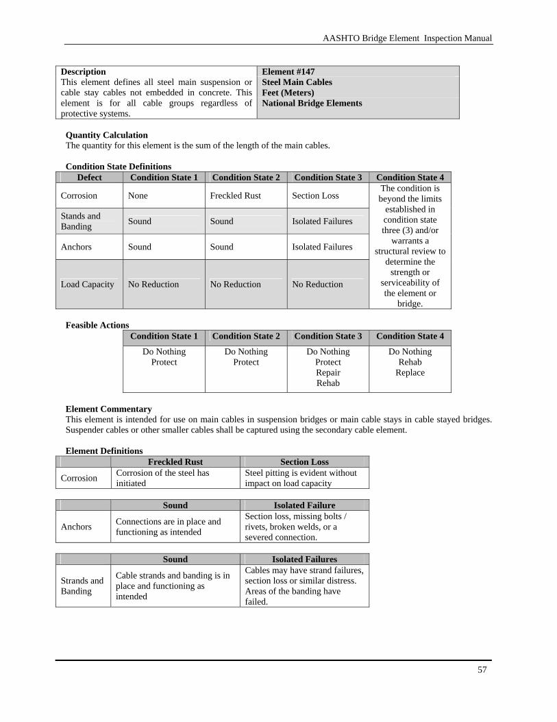
AASHTO Bridge Element Inspection Manual
57
Element #147 Steel Main Cables Feet (Meters)
Description This element defines all steel main suspension or cable stay cables not embedded in concrete. This element is for all cable groups regardless of protective systems.
National Bridge Elements
Quantity Calculation The quantity for this element is the sum of the length of the main cables. Condition State Definitions
Defect Condition State 1 Condition State 2 Condition State 3 Condition State 4
Corrosion None Freckled Rust Section Loss
Stands and Banding Sound Sound Isolated Failures
Anchors Sound Sound Isolated Failures
Load Capacity No Reduction No Reduction No Reduction
The condition is beyond the limits
established in condition state three (3) and/or
warrants a structural review to
determine the strength or
serviceability of the element or
bridge. Feasible Actions
Condition State 1 Condition State 2 Condition State 3 Condition State 4
Do Nothing Protect
Do Nothing Protect
Do Nothing Protect Repair Rehab
Do Nothing Rehab
Replace
Element Commentary This element is intended for use on main cables in suspension bridges or main cable stays in cable stayed bridges. Suspender cables or other smaller cables shall be captured using the secondary cable element. Element Definitions
Freckled Rust Section Loss
Corrosion Corrosion of the steel has initiated
Steel pitting is evident without impact on load capacity
Sound Isolated Failure
Anchors Connections are in place and functioning as intended
Section loss, missing bolts / rivets, broken welds, or a severed connection.
Sound Isolated Failures
Strands and Banding
Cable strands and banding is in place and functioning as intended
Cables may have strand failures, section loss or similar distress. Areas of the banding have failed.
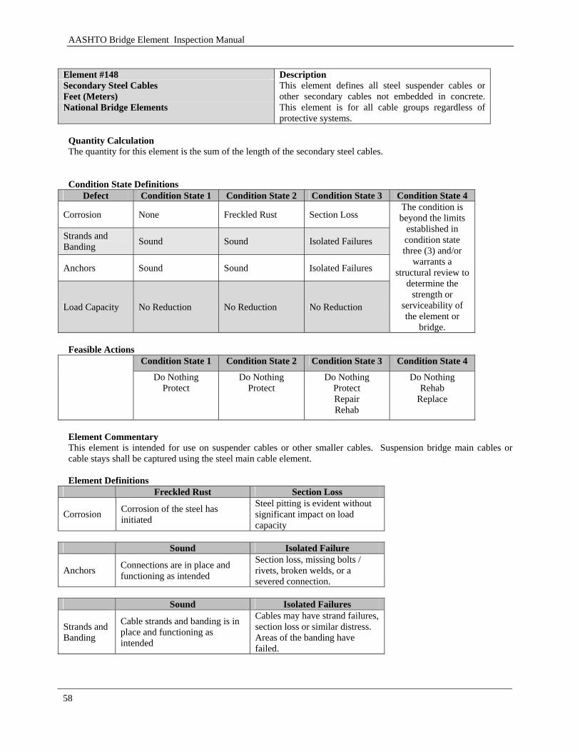
AASHTO Bridge Element Inspection Manual
58
Element #148 Secondary Steel Cables Feet (Meters) National Bridge Elements
Description This element defines all steel suspender cables or other secondary cables not embedded in concrete. This element is for all cable groups regardless of protective systems.
Quantity Calculation The quantity for this element is the sum of the length of the secondary steel cables. Condition State Definitions
Defect Condition State 1 Condition State 2 Condition State 3 Condition State 4
Corrosion None Freckled Rust Section Loss
Strands and Banding Sound Sound Isolated Failures
Anchors Sound Sound Isolated Failures
Load Capacity No Reduction No Reduction No Reduction
The condition is beyond the limits
established in condition state three (3) and/or
warrants a structural review to
determine the strength or
serviceability of the element or
bridge. Feasible Actions
Condition State 1 Condition State 2 Condition State 3 Condition State 4
Do Nothing Protect
Do Nothing Protect
Do Nothing Protect Repair Rehab
Do Nothing Rehab
Replace
Element Commentary This element is intended for use on suspender cables or other smaller cables. Suspension bridge main cables or cable stays shall be captured using the steel main cable element. Element Definitions
Freckled Rust Section Loss
Corrosion Corrosion of the steel has initiated
Steel pitting is evident without significant impact on load capacity
Sound Isolated Failure
Anchors Connections are in place and functioning as intended
Section loss, missing bolts / rivets, broken welds, or a severed connection.
Sound Isolated Failures
Strands and Banding
Cable strands and banding is in place and functioning as intended
Cables may have strand failures, section loss or similar distress. Areas of the banding have failed.
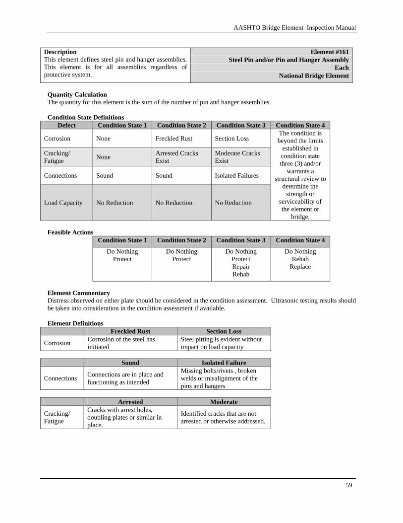
AASHTO Bridge Element Inspection Manual
59
Element #161
Steel Pin and/or Pin and Hanger Assembly Each
Description This element defines steel pin and hanger assemblies. This element is for all assemblies regardless of protective system. National Bridge Element
Quantity Calculation The quantity for this element is the sum of the number of pin and hanger assemblies. Condition State Definitions
Defect Condition State 1 Condition State 2 Condition State 3 Condition State 4
Corrosion None Freckled Rust Section Loss
Cracking/ Fatigue None Arrested Cracks
Exist Moderate Cracks Exist
Connections Sound Sound Isolated Failures
Load Capacity No Reduction No Reduction No Reduction
The condition is beyond the limits
established in condition state three (3) and/or
warrants a structural review to
determine the strength or
serviceability of the element or
bridge. Feasible Actions
Condition State 1 Condition State 2 Condition State 3 Condition State 4
Do Nothing Protect
Do Nothing Protect
Do Nothing Protect Repair Rehab
Do Nothing Rehab
Replace
Element Commentary Distress observed on either plate should be considered in the condition assessment. Ultrasonic testing results should be taken into consideration in the condition assessment if available. Element Definitions
Freckled Rust Section Loss
Corrosion Corrosion of the steel has initiated
Steel pitting is evident without impact on load capacity
Sound Isolated Failure
Connections Connections are in place and functioning as intended
Missing bolts/rivets , broken welds or misalignment of the pins and hangers
Arrested Moderate
Cracking/ Fatigue
Cracks with arrest holes, doubling plates or similar in place.
Identified cracks that are not arrested or otherwise addressed.
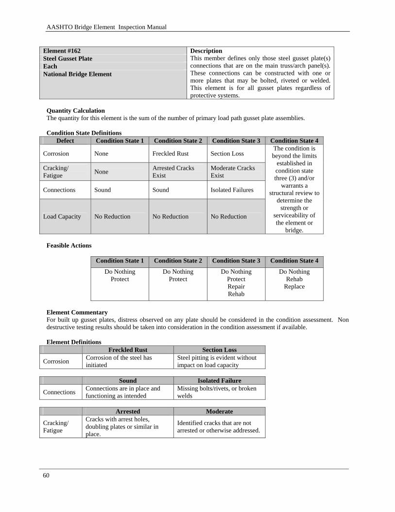
AASHTO Bridge Element Inspection Manual
60
Element #162 Steel Gusset Plate Each National Bridge Element
Description This member defines only those steel gusset plate(s) connections that are on the main truss/arch panel(s). These connections can be constructed with one or more plates that may be bolted, riveted or welded. This element is for all gusset plates regardless of protective systems.
Quantity Calculation The quantity for this element is the sum of the number of primary load path gusset plate assemblies. Condition State Definitions
Defect Condition State 1 Condition State 2 Condition State 3 Condition State 4
Corrosion None Freckled Rust Section Loss
Cracking/ Fatigue None Arrested Cracks
Exist Moderate Cracks Exist
Connections Sound Sound Isolated Failures
Load Capacity No Reduction No Reduction No Reduction
The condition is beyond the limits
established in condition state three (3) and/or
warrants a structural review to
determine the strength or
serviceability of the element or
bridge. Feasible Actions
Condition State 1 Condition State 2 Condition State 3 Condition State 4
Do Nothing Protect
Do Nothing Protect
Do Nothing Protect Repair Rehab
Do Nothing Rehab
Replace
Element Commentary For built up gusset plates, distress observed on any plate should be considered in the condition assessment. Non destructive testing results should be taken into consideration in the condition assessment if available. Element Definitions
Freckled Rust Section Loss
Corrosion Corrosion of the steel has initiated
Steel pitting is evident without impact on load capacity
Sound Isolated Failure
Connections Connections are in place and functioning as intended
Missing bolts/rivets, or broken welds
Arrested Moderate
Cracking/ Fatigue
Cracks with arrest holes, doubling plates or similar in place.
Identified cracks that are not arrested or otherwise addressed.

AASHTO Bridge Element Inspection Manual
61
[BLANK PAGE]
AASHTO Bridge Element Inspection Manual
62
3.1.8 Substructure Elements
Substructure elements described in this section transmit the load from the superstructure into the ground. These elements include columns, piles, pile cap, pile extensions, caps, pier walls and abutments. These elements include elements of steel, concrete, timber, masonry and other materials.
3.1.9 Columns/Pile/Pier Wall
This section covers supporting elements the span of the structure. These items include columns pile extensions, piles and pier walls.

AASHTO Bridge Element Inspection Manual
63
Element #202 Steel Column or Pile Extension
Each
Description This element defines only those steel columns or pile extensions. Piles exposed from erosion or included as part of the diver inspection are not included in this element. This element is for all columns/pile extensions regardless of protective system.
National Bridge Element
Quantity Calculation The quantity for this element is the sum of the number of columns or pile extensions. Condition State Definitions
Defect Condition State 1 Condition State 2 Condition State 3 Condition State 4
Corrosion None Freckled Rust Section Loss
Cracking/ Fatigue None Arrested Cracks Exist Unarrested Cracks Exist
Connections Sound Sound Isolated Failures
Scour None Arrestment And/ Or Countermeasures Exists Minor
Settlement None Arrestment And/ Or Countermeasures Exists Minor
Load Capacity No Reduction No Reduction No Reduction
The condition is beyond the limits
established in condition state three (3) and/or
warrants a structural review to
determine the strength or
serviceability of the element or
bridge.
Feasible Actions
Condition State 1 Condition State 2 Condition State 3 Condition State 4
Do Nothing Protect
Do Nothing Protect
Do Nothing Protect Repair Rehab
Do Nothing Rehab
Replace
Element Commentary None Element Definitions
Freckled Rust Section Loss Corrosion Corrosion of the steel has initiated Steel pitting is evident without
significant impact on load capacity
Sound Isolated Failure
Connections Connections are in place and functioning as intended
Missing bolts/rivets, broken welds or a severed connection.
Arrested Moderate
Cracking/ Fatigue
Cracks with arrest holes, doubling plates or similar in place.
Identified cracks that are not arrested or otherwise addressed.
Defect Minor
Scour Scour exists - the structure remains stable
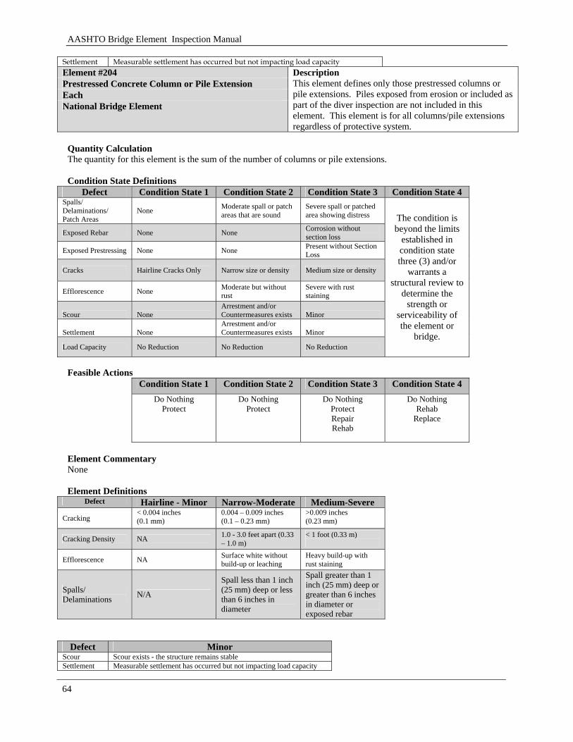
AASHTO Bridge Element Inspection Manual
64
Settlement Measurable settlement has occurred but not impacting load capacity Element #204 Prestressed Concrete Column or Pile Extension Each National Bridge Element
Description This element defines only those prestressed columns or pile extensions. Piles exposed from erosion or included as part of the diver inspection are not included in this element. This element is for all columns/pile extensions regardless of protective system.
Quantity Calculation The quantity for this element is the sum of the number of columns or pile extensions. Condition State Definitions
Defect Condition State 1 Condition State 2 Condition State 3 Condition State 4 Spalls/ Delaminations/ Patch Areas
None Moderate spall or patch areas that are sound
Severe spall or patched area showing distress
Exposed Rebar None None Corrosion without section loss
Exposed Prestressing None None Present without Section Loss
Cracks Hairline Cracks Only Narrow size or density Medium size or density
Efflorescence None Moderate but without rust
Severe with rust staining
Scour None Arrestment and/or Countermeasures exists Minor
Settlement None Arrestment and/or Countermeasures exists Minor
Load Capacity No Reduction No Reduction No Reduction
The condition is beyond the limits
established in condition state three (3) and/or
warrants a structural review to
determine the strength or
serviceability of the element or
bridge.
Feasible Actions
Condition State 1 Condition State 2 Condition State 3 Condition State 4 Do Nothing
Protect Do Nothing
Protect Do Nothing
Protect Repair Rehab
Do Nothing Rehab
Replace
Element Commentary None Element Definitions
Defect Hairline - Minor Narrow-Moderate Medium-Severe Cracking
< 0.004 inches (0.1 mm)
0.004 – 0.009 inches (0.1 – 0.23 mm)
>0.009 inches (0.23 mm)
Cracking Density NA 1.0 - 3.0 feet apart (0.33 – 1.0 m)
< 1 foot (0.33 m)
Efflorescence NA Surface white without build-up or leaching
Heavy build-up with rust staining
Spalls/ Delaminations N/A
Spall less than 1 inch (25 mm) deep or less than 6 inches in diameter
Spall greater than 1 inch (25 mm) deep or greater than 6 inches in diameter or exposed rebar
Defect Minor
Scour Scour exists - the structure remains stable Settlement Measurable settlement has occurred but not impacting load capacity
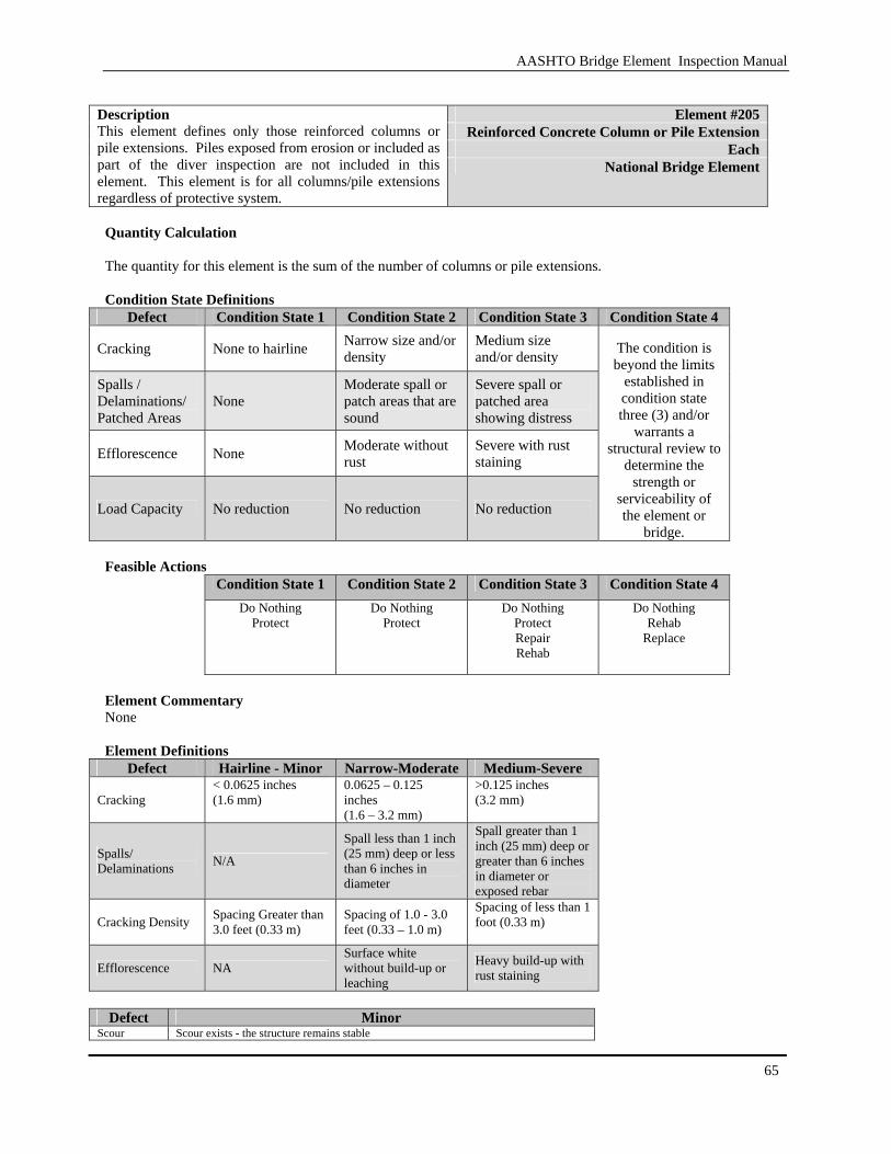
AASHTO Bridge Element Inspection Manual
65
Element #205
Reinforced Concrete Column or Pile Extension Each
Description This element defines only those reinforced columns or pile extensions. Piles exposed from erosion or included as part of the diver inspection are not included in this element. This element is for all columns/pile extensions regardless of protective system.
National Bridge Element
Quantity Calculation The quantity for this element is the sum of the number of columns or pile extensions. Condition State Definitions
Defect Condition State 1 Condition State 2 Condition State 3 Condition State 4
Cracking None to hairline Narrow size and/or density
Medium size and/or density
Spalls / Delaminations/ Patched Areas
None Moderate spall or patch areas that are sound
Severe spall or patched area showing distress
Efflorescence None Moderate without rust
Severe with rust staining
Load Capacity No reduction No reduction No reduction
The condition is beyond the limits
established in condition state three (3) and/or
warrants a structural review to
determine the strength or
serviceability of the element or
bridge. Feasible Actions
Condition State 1 Condition State 2 Condition State 3 Condition State 4
Do Nothing Protect
Do Nothing Protect
Do Nothing Protect Repair Rehab
Do Nothing Rehab
Replace
Element Commentary None Element Definitions
Defect Hairline - Minor Narrow-Moderate Medium-Severe
Cracking < 0.0625 inches (1.6 mm)
0.0625 – 0.125 inches (1.6 – 3.2 mm)
>0.125 inches (3.2 mm)
Spalls/ Delaminations N/A
Spall less than 1 inch (25 mm) deep or less than 6 inches in diameter
Spall greater than 1 inch (25 mm) deep or greater than 6 inches in diameter or exposed rebar
Cracking Density Spacing Greater than 3.0 feet (0.33 m)
Spacing of 1.0 - 3.0 feet (0.33 – 1.0 m)
Spacing of less than 1 foot (0.33 m)
Efflorescence NA Surface white without build-up or leaching
Heavy build-up with rust staining
Defect Minor
Scour Scour exists - the structure remains stable

AASHTO Bridge Element Inspection Manual
66
Settlement Measurable settlement has occurred but not impacting load capacity Element #206 Timber Column or Pile Extension Each National Bridge Elements
Description This element defines only those timber columns or pile extensions. Piles exposed from erosion or included as part of the diver inspection are not included in this element. This element is for all columns/pile extensions regardless of protective system.
Quantity Calculation The quantity of this element is the number of columns or pile extensions. Condition State Definitions
Defect Condition State 1 Condition State 2 Condition State 3 Condition State 4 Decay None None Moderate Checks/Shingles Minor Moderate Severe Cracks None None Minor Splits Minor Minor to Moderate Minor to Moderate Abrasion Minor Minor Moderate
Scour None
Arrestment and/or Countermeasures exists Minor
Settlement None
Arrestment and/or Countermeasures exists Minor
Load Capacity No reduction No reduction No reduction
The condition is beyond the limits
established in condition state three (3) and/or warrants a structural review to
determine the strength or
serviceability of the element or bridge.
Feasible Actions
Condition State 1 Condition State 2 Condition State 3 Condition State 4
Do Nothing Protect
Do Nothing Protect Repair
Do Nothing Protect Repair Rehab
Do Nothing Rehab
Replace
Element Commentary None Element Definitions Defect Minor Moderate Severe
Decay Surface penetration only Less than 10% of the thickness of the member
Decay greater than 10% of the thickness of the member and/or is in tension zones
Checks / Shingles
Surface level and does not penetrate more than 5% of the member thickness
Defect does not penetrate more than 50% of the thickness of the member and/or in the areas of neutral axis
Defect penetrating more that 50% of the thickness of the member and/or in areas of the tension zone.
Splits Lengthwise separation of wood from one surface through to the opposite or adjacent surface. Length does not exceed the depth of the member.
Length of the split is less than 25% of the member length.
Length of the split is greater than 25% of the member length.
Abrasion Surface level, no section loss Section loss no less than 10% of the thickness of the member
Section loss more than 10% of the thickness of the member
Cracks Propagates from a compression zone surface or propagates from a tension surface but penetrates less than 10% of the depth of the member.
Propagates from a tension zone surface to a depth not greater than 50% of the member depth.
Propagates from a tension zone to a depth greater than 50% of the member depth.
Defect Minor
Scour Scour exists - the structure remains stable Settlement Measurable settlement has occurred but not impacting load capacity
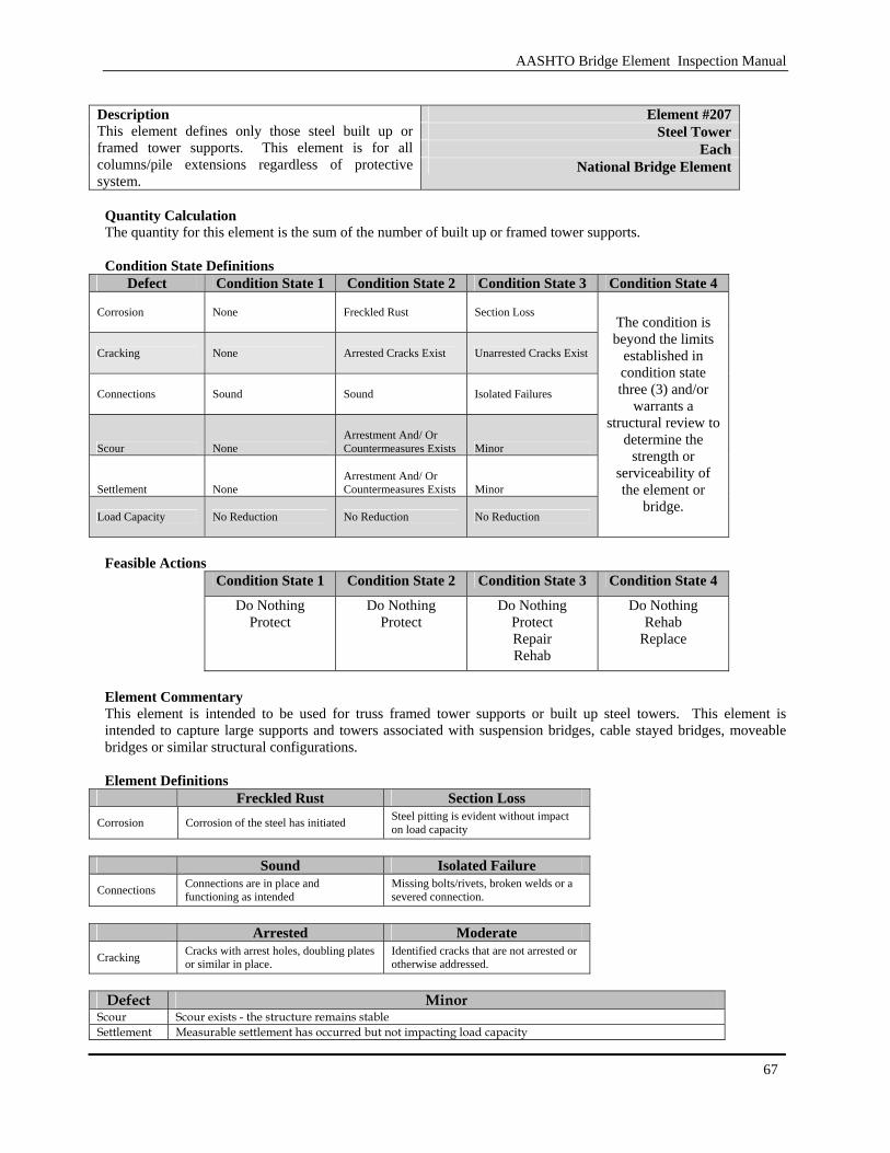
AASHTO Bridge Element Inspection Manual
67
Element #207
Steel Tower Each
Description This element defines only those steel built up or framed tower supports. This element is for all columns/pile extensions regardless of protective system.
National Bridge Element
Quantity Calculation The quantity for this element is the sum of the number of built up or framed tower supports. Condition State Definitions
Defect Condition State 1 Condition State 2 Condition State 3 Condition State 4
Corrosion None Freckled Rust Section Loss
Cracking None Arrested Cracks Exist Unarrested Cracks Exist
Connections Sound Sound Isolated Failures
Scour None Arrestment And/ Or Countermeasures Exists Minor
Settlement None Arrestment And/ Or Countermeasures Exists Minor
Load Capacity No Reduction No Reduction No Reduction
The condition is beyond the limits
established in condition state three (3) and/or
warrants a structural review to
determine the strength or
serviceability of the element or
bridge.
Feasible Actions
Condition State 1 Condition State 2 Condition State 3 Condition State 4
Do Nothing Protect
Do Nothing Protect
Do Nothing Protect Repair Rehab
Do Nothing Rehab
Replace
Element Commentary This element is intended to be used for truss framed tower supports or built up steel towers. This element is intended to capture large supports and towers associated with suspension bridges, cable stayed bridges, moveable bridges or similar structural configurations. Element Definitions
Freckled Rust Section Loss Corrosion Corrosion of the steel has initiated Steel pitting is evident without impact
on load capacity
Sound Isolated Failure
Connections Connections are in place and functioning as intended
Missing bolts/rivets, broken welds or a severed connection.
Arrested Moderate
Cracking Cracks with arrest holes, doubling plates or similar in place.
Identified cracks that are not arrested or otherwise addressed.
Defect Minor
Scour Scour exists - the structure remains stable Settlement Measurable settlement has occurred but not impacting load capacity
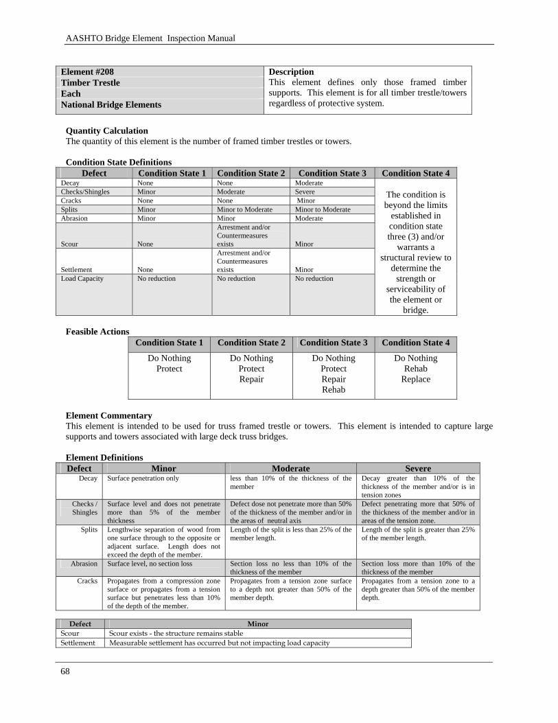
AASHTO Bridge Element Inspection Manual
68
Element #208 Timber Trestle Each National Bridge Elements
Description This element defines only those framed timber supports. This element is for all timber trestle/towers regardless of protective system.
Quantity Calculation The quantity of this element is the number of framed timber trestles or towers. Condition State Definitions
Defect Condition State 1 Condition State 2 Condition State 3 Condition State 4 Decay None None Moderate Checks/Shingles Minor Moderate Severe Cracks None None Minor Splits Minor Minor to Moderate Minor to Moderate Abrasion Minor Minor Moderate
Scour None
Arrestment and/or Countermeasures exists Minor
Settlement None
Arrestment and/or Countermeasures exists Minor
Load Capacity No reduction No reduction No reduction
The condition is beyond the limits
established in condition state three (3) and/or
warrants a structural review to
determine the strength or
serviceability of the element or
bridge. Feasible Actions
Condition State 1 Condition State 2 Condition State 3 Condition State 4
Do Nothing Protect
Do Nothing Protect Repair
Do Nothing Protect Repair Rehab
Do Nothing Rehab
Replace
Element Commentary This element is intended to be used for truss framed trestle or towers. This element is intended to capture large supports and towers associated with large deck truss bridges. Element Definitions Defect Minor Moderate Severe
Decay Surface penetration only less than 10% of the thickness of the member
Decay greater than 10% of the thickness of the member and/or is in tension zones
Checks / Shingles
Surface level and does not penetrate more than 5% of the member thickness
Defect dose not penetrate more than 50% of the thickness of the member and/or in the areas of neutral axis
Defect penetrating more that 50% of the thickness of the member and/or in areas of the tension zone.
Splits Lengthwise separation of wood from one surface through to the opposite or adjacent surface. Length does not exceed the depth of the member.
Length of the split is less than 25% of the member length.
Length of the split is greater than 25% of the member length.
Abrasion Surface level, no section loss Section loss no less than 10% of the thickness of the member
Section loss more than 10% of the thickness of the member
Cracks Propagates from a compression zone surface or propagates from a tension surface but penetrates less than 10% of the depth of the member.
Propagates from a tension zone surface to a depth not greater than 50% of the member depth.
Propagates from a tension zone to a depth greater than 50% of the member depth.
Defect Minor
Scour Scour exists - the structure remains stable Settlement Measurable settlement has occurred but not impacting load capacity
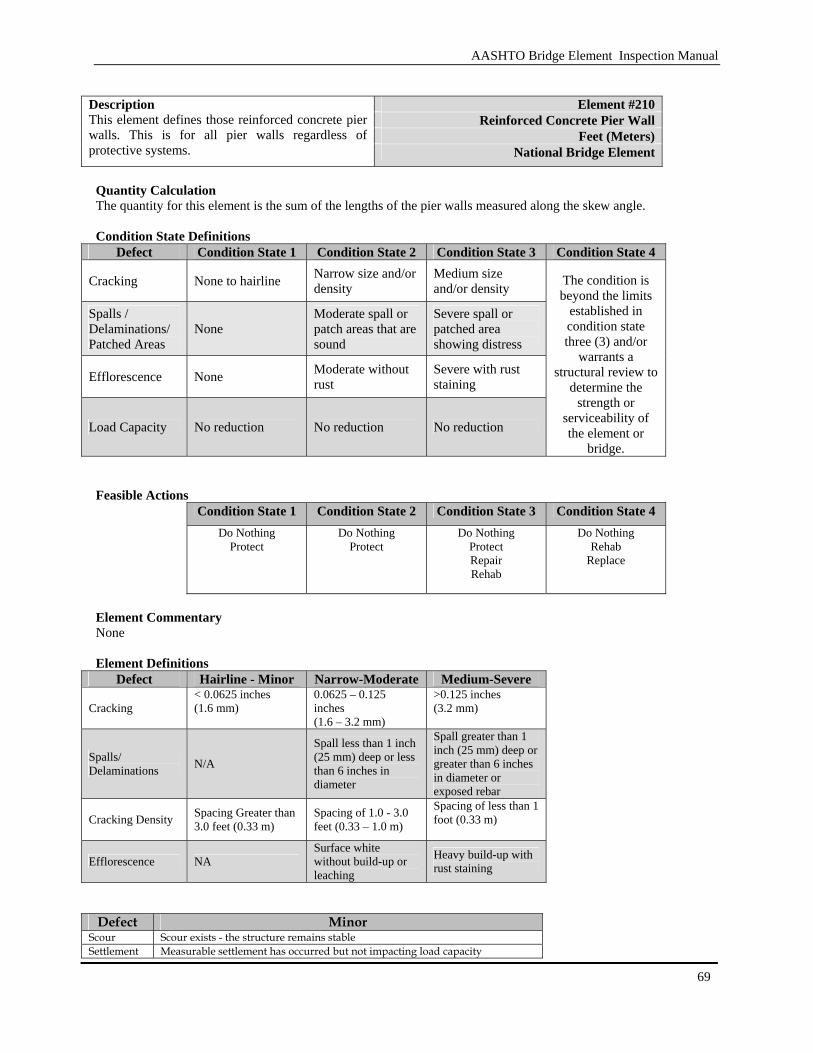
AASHTO Bridge Element Inspection Manual
69
Element #210
Reinforced Concrete Pier Wall Feet (Meters)
Description This element defines those reinforced concrete pier walls. This is for all pier walls regardless of protective systems. National Bridge Element
Quantity Calculation The quantity for this element is the sum of the lengths of the pier walls measured along the skew angle. Condition State Definitions
Defect Condition State 1 Condition State 2 Condition State 3 Condition State 4
Cracking None to hairline Narrow size and/or density
Medium size and/or density
Spalls / Delaminations/ Patched Areas
None Moderate spall or patch areas that are sound
Severe spall or patched area showing distress
Efflorescence None Moderate without rust
Severe with rust staining
Load Capacity No reduction No reduction No reduction
The condition is beyond the limits
established in condition state three (3) and/or
warrants a structural review to
determine the strength or
serviceability of the element or
bridge. Feasible Actions
Condition State 1 Condition State 2 Condition State 3 Condition State 4 Do Nothing
Protect Do Nothing
Protect Do Nothing
Protect Repair Rehab
Do Nothing Rehab
Replace
Element Commentary None Element Definitions
Defect Hairline - Minor Narrow-Moderate Medium-Severe
Cracking < 0.0625 inches (1.6 mm)
0.0625 – 0.125 inches (1.6 – 3.2 mm)
>0.125 inches (3.2 mm)
Spalls/ Delaminations N/A
Spall less than 1 inch (25 mm) deep or less than 6 inches in diameter
Spall greater than 1 inch (25 mm) deep or greater than 6 inches in diameter or exposed rebar
Cracking Density Spacing Greater than 3.0 feet (0.33 m)
Spacing of 1.0 - 3.0 feet (0.33 – 1.0 m)
Spacing of less than 1 foot (0.33 m)
Efflorescence NA Surface white without build-up or leaching
Heavy build-up with rust staining
Defect Minor
Scour Scour exists - the structure remains stable Settlement Measurable settlement has occurred but not impacting load capacity
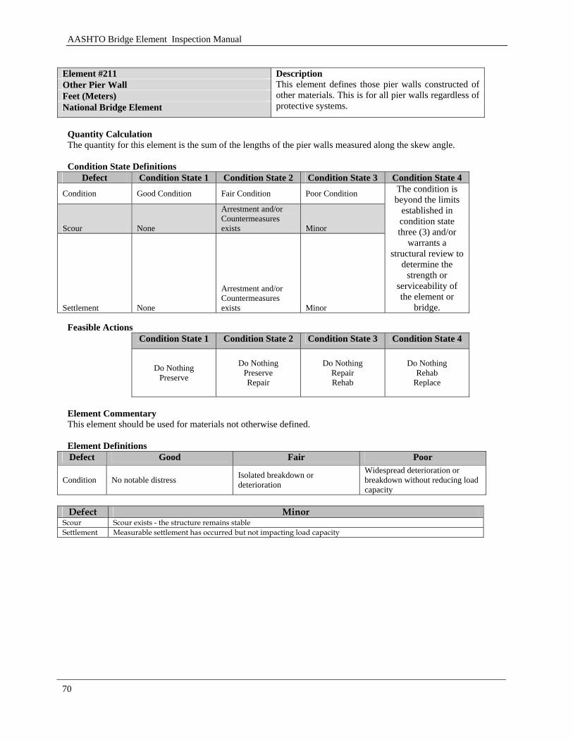
AASHTO Bridge Element Inspection Manual
70
Element #211 Other Pier Wall Feet (Meters) National Bridge Element
Description This element defines those pier walls constructed of other materials. This is for all pier walls regardless of protective systems.
Quantity Calculation The quantity for this element is the sum of the lengths of the pier walls measured along the skew angle. Condition State Definitions
Defect Condition State 1 Condition State 2 Condition State 3 Condition State 4
Condition Good Condition Fair Condition Poor Condition
Scour None
Arrestment and/or Countermeasures exists Minor
Settlement None
Arrestment and/or Countermeasures exists Minor
The condition is beyond the limits
established in condition state three (3) and/or
warrants a structural review to
determine the strength or
serviceability of the element or
bridge. Feasible Actions
Condition State 1 Condition State 2 Condition State 3 Condition State 4
Do Nothing
Preserve
Do Nothing Preserve Repair
Do Nothing Repair Rehab
Do Nothing Rehab
Replace
Element Commentary This element should be used for materials not otherwise defined. Element Definitions Defect Good Fair Poor
Condition No notable distress Isolated breakdown or deterioration
Widespread deterioration or breakdown without reducing load capacity
Defect Minor
Scour Scour exists - the structure remains stable Settlement Measurable settlement has occurred but not impacting load capacity
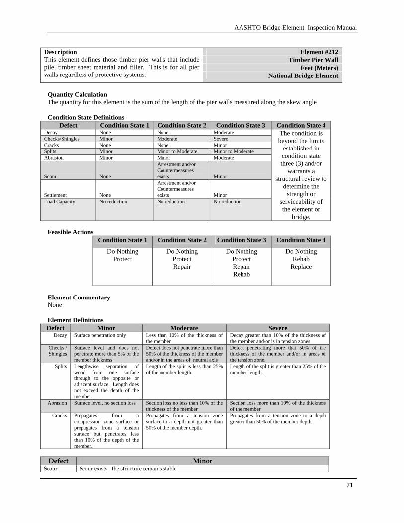
AASHTO Bridge Element Inspection Manual
71
Element #212
Timber Pier Wall Feet (Meters)
Description This element defines those timber pier walls that include pile, timber sheet material and filler. This is for all pier walls regardless of protective systems. National Bridge Element
Quantity Calculation The quantity for this element is the sum of the length of the pier walls measured along the skew angle Condition State Definitions
Defect Condition State 1 Condition State 2 Condition State 3 Condition State 4 Decay None None Moderate Checks/Shingles Minor Moderate Severe Cracks None None Minor Splits Minor Minor to Moderate Minor to Moderate Abrasion Minor Minor Moderate
Scour None
Arrestment and/or Countermeasures exists Minor
Settlement None
Arrestment and/or Countermeasures exists Minor
Load Capacity No reduction No reduction No reduction
The condition is beyond the limits
established in condition state three (3) and/or
warrants a structural review to
determine the strength or
serviceability of the element or
bridge. Feasible Actions
Condition State 1 Condition State 2 Condition State 3 Condition State 4
Do Nothing Protect
Do Nothing Protect Repair
Do Nothing Protect Repair Rehab
Do Nothing Rehab
Replace
Element Commentary None Element Definitions Defect Minor Moderate Severe
Decay Surface penetration only Less than 10% of the thickness of the member
Decay greater than 10% of the thickness of the member and/or is in tension zones
Checks / Shingles
Surface level and does not penetrate more than 5% of the member thickness
Defect does not penetrate more than 50% of the thickness of the member and/or in the areas of neutral axis
Defect penetrating more that 50% of the thickness of the member and/or in areas of the tension zone.
Splits Lengthwise separation of wood from one surface through to the opposite or adjacent surface. Length does not exceed the depth of the member.
Length of the split is less than 25% of the member length.
Length of the split is greater than 25% of the member length.
Abrasion Surface level, no section loss Section loss no less than 10% of the thickness of the member
Section loss more than 10% of the thickness of the member
Cracks Propagates from a compression zone surface or propagates from a tension surface but penetrates less than 10% of the depth of the member.
Propagates from a tension zone surface to a depth not greater than 50% of the member depth.
Propagates from a tension zone to a depth greater than 50% of the member depth.
Defect Minor
Scour Scour exists - the structure remains stable

AASHTO Bridge Element Inspection Manual
72
Settlement Measurable settlement has occurred but not impacting load capacity Element #213 Masonry Pier Wall Feet (Meters) National Bridge Elements
Description This element defines those pier walls constructed of block or stone. The block or stone may be placed with or without mortar. This is for all pier walls regardless of protective systems.
Quantity Calculation The quantity for this element is the sum of the wall lengths measured along the skew. Condition State Definitions
Defect Condition State 1 Condition State 2 Condition State 3 Condition State 4 Mortar Breakdown None Cracking and/or
moderate voids Severe cracking or voids
Block or Stone
Cracks are present but have not allowed the block or stone to shift
Cracks are present and block or stone has minor shifting
Block or Stone are cracked with masonry face deformation. Block or stone are missing
Efflorescence None Moderate but without rust
Severe with rust staining
Patched Areas None Present Present
Load Capacity No Reduction No Reduction No Reduction
The condition is beyond the limits
established in condition state three (3) and/or
warrants a structural review to
determine the strength or
serviceability of the element or
bridge.
Feasible Actions
Condition State 1 Condition State 2 Condition State 3 Condition State 4 Do Nothing
Protect Do Nothing
Protect Do Nothing
Protect Repair Rehab
Do Nothing Rehab
Replace
Element Commentary None Element Definitions
Defect Moderate Severe
Cracking 0.02– 0.08 inches (0.5 – 2.0 mm)
>0.08 inches (2.0 mm)
Cracking Density 1.0 - 3.0 feet apart (0.33 – 1.0 m)
< 1 foot (0.33 m)
Mortar Breakdown
Cracking or voids in less than 10% of joints
Cracking or voids in more than 10% of joints
Efflorescence Surface white without build-up or leaching
Heavy build-up with rust staining
Defect Minor
Scour Scour exists – the structure remains stable Settlement Measurable settlement has occurred but not impacting load capacity
AASHTO Bridge Element Inspection Manual
73
3.1.10 Abutments
This section covers the abutments for the structure. The materials covered are steel, concrete, masonry, and other material abutments.

AASHTO Bridge Element Inspection Manual
74
[BLANK PAGE]
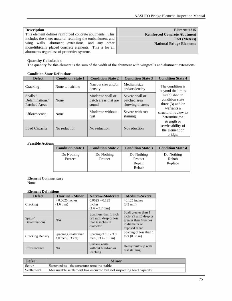
AASHTO Bridge Element Inspection Manual
75
Element #215
Reinforced Concrete Abutment Feet (Meters)
Description This element defines reinforced concrete abutments. This includes the sheet material retaining the embankment and wing walls, abutment extensions, and any other monolithically placed concrete elements. This is for all abutments regardless of protective systems.
National Bridge Elements
Quantity Calculation The quantity for this element is the sum of the width of the abutment with wingwalls and abutment extensions. Condition State Definitions
Defect Condition State 1 Condition State 2 Condition State 3 Condition State 4
Cracking None to hairline Narrow size and/or density
Medium size and/or density
Spalls / Delaminations/ Patched Areas
None Moderate spall or patch areas that are sound
Severe spall or patched area showing distress
Efflorescence None Moderate without rust
Severe with rust staining
Load Capacity No reduction No reduction No reduction
The condition is beyond the limits
established in condition state three (3) and/or
warrants a structural review to
determine the strength or
serviceability of the element or
bridge. Feasible Actions
Condition State 1 Condition State 2 Condition State 3 Condition State 4 Do Nothing
Protect Do Nothing
Protect Do Nothing
Protect Repair Rehab
Do Nothing Rehab
Replace
Element Commentary None Element Definitions
Defect Hairline - Minor Narrow-Moderate Medium-Severe
Cracking < 0.0625 inches (1.6 mm)
0.0625 – 0.125 inches (1.6 – 3.2 mm)
>0.125 inches (3.2 mm)
Spalls/ Delaminations N/A
Spall less than 1 inch (25 mm) deep or less than 6 inches in diameter
Spall greater than 1 inch (25 mm) deep or greater than 6 inches in diameter or exposed rebar
Cracking Density Spacing Greater than 3.0 feet (0.33 m)
Spacing of 1.0 - 3.0 feet (0.33 – 1.0 m)
Spacing of less than 1 foot (0.33 m)
Efflorescence NA Surface white without build-up or leaching
Heavy build-up with rust staining
Defect Minor Scour Scour exists - the structure remains stable Settlement Measurable settlement has occurred but not impacting load capacity
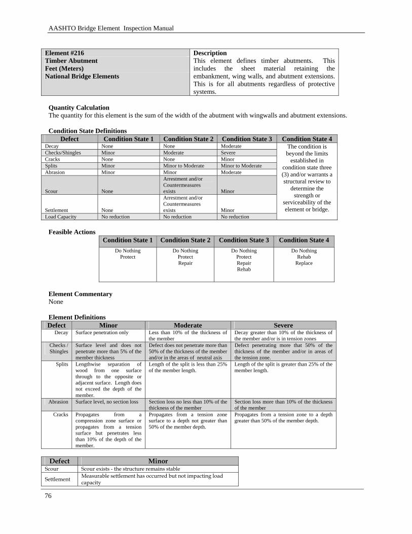
AASHTO Bridge Element Inspection Manual
76
Element #216 Timber Abutment Feet (Meters) National Bridge Elements
Description This element defines timber abutments. This includes the sheet material retaining the embankment, wing walls, and abutment extensions. This is for all abutments regardless of protective systems.
Quantity Calculation The quantity for this element is the sum of the width of the abutment with wingwalls and abutment extensions. Condition State Definitions
Defect Condition State 1 Condition State 2 Condition State 3 Condition State 4 Decay None None Moderate Checks/Shingles Minor Moderate Severe Cracks None None Minor Splits Minor Minor to Moderate Minor to Moderate Abrasion Minor Minor Moderate
Scour None
Arrestment and/or Countermeasures exists Minor
Settlement None
Arrestment and/or Countermeasures exists Minor
Load Capacity No reduction No reduction No reduction
The condition is beyond the limits
established in condition state three (3) and/or warrants a structural review to
determine the strength or
serviceability of the element or bridge.
Feasible Actions
Condition State 1 Condition State 2 Condition State 3 Condition State 4
Do Nothing Protect
Do Nothing Protect Repair
Do Nothing Protect Repair Rehab
Do Nothing Rehab
Replace
Element Commentary None Element Definitions Defect Minor Moderate Severe
Decay Surface penetration only Less than 10% of the thickness of the member
Decay greater than 10% of the thickness of the member and/or is in tension zones
Checks / Shingles
Surface level and does not penetrate more than 5% of the member thickness
Defect does not penetrate more than 50% of the thickness of the member and/or in the areas of neutral axis
Defect penetrating more that 50% of the thickness of the member and/or in areas of the tension zone.
Splits Lengthwise separation of wood from one surface through to the opposite or adjacent surface. Length does not exceed the depth of the member.
Length of the split is less than 25% of the member length.
Length of the split is greater than 25% of the member length.
Abrasion Surface level, no section loss Section loss no less than 10% of the thickness of the member
Section loss more than 10% of the thickness of the member
Cracks Propagates from a compression zone surface or propagates from a tension surface but penetrates less than 10% of the depth of the member.
Propagates from a tension zone surface to a depth not greater than 50% of the member depth.
Propagates from a tension zone to a depth greater than 50% of the member depth.
Defect Minor
Scour Scour exists - the structure remains stable
Settlement Measurable settlement has occurred but not impacting load capacity
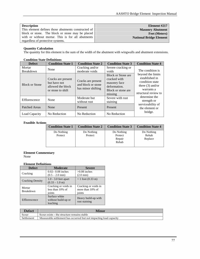
AASHTO Bridge Element Inspection Manual
77
Element #217
Masonry Abutment Feet (Meters)
Description This element defines those abutments constructed of block or stone. The block or stone may be placed with or without mortar. This is for all abutments regardless of protective systems.
National Bridge Element
Quantity Calculation The quantity for this element is the sum of the width of the abutment with wingwalls and abutment extensions. Condition State Definitions
Defect Condition State 1 Condition State 2 Condition State 3 Condition State 4 Mortar Breakdown None Cracking and/or
moderate voids Severe cracking or voids
Block or Stone
Cracks are present but have not allowed the block or stone to shift
Cracks are present and block or stone has minor shifting
Block or Stone are cracked with masonry face deformation. Block or stone are missing
Efflorescence None Moderate but without rust
Severe with rust staining
Patched Areas None Present Present
Load Capacity No Reduction No Reduction No Reduction
The condition is beyond the limits
established in condition state three (3) and/or
warrants a structural review to
determine the strength or
serviceability of the element or
bridge.
Feasible Actions
Condition State 1 Condition State 2 Condition State 3 Condition State 4
Do Nothing Protect
Do Nothing Protect
Do Nothing Protect Repair Rehab
Do Nothing Rehab
Replace
Element Commentary None Element Definitions
Defect Moderate Severe
Cracking 0.02– 0.08 inches (0.5 – 2.0 mm)
>0.08 inches (2.0 mm)
Cracking Density 1.0 - 3.0 feet apart (0.33 – 1.0 m)
< 1 foot (0.33 m)
Mortar Breakdown
Cracking or voids in less than 10% of joints
Cracking or voids in more than 10% of joints
Efflorescence Surface white without build-up or leaching
Heavy build-up with rust staining
Defect Minor
Scour Scour exists – the structure remains stable Settlement Measurable settlement has occurred but not impacting load capacity

AASHTO Bridge Element Inspection Manual
78
Element #218 Other Abutments Feet (Meters) National Bridge Element
Description This element defines other material abutments systems. This includes the sheet material retaining the embankment, wing walls, and abutment extensions. This is for all abutments regardless of protective systems.
Quantity Calculation The quantity of this element is the sum of the lengths of the abutments measured along the skew angle. Condition State Definitions
Defect Condition State 1 Condition State 2 Condition State 3 Condition State 4
Condition Good Condition Fair Condition Poor Condition
Scour None Arrestment and/or Countermeasures
exists Minor
Settlement None Arrestment and/or Countermeasures
exists Minor
The condition is beyond the limits
established in condition state three (3) and/or
warrants a structural review to
determine the strength or
serviceability of the element or
bridge. Feasible Actions
Condition State 1 Condition State 2 Condition State 3 Condition State 4
Do Nothing
Preserve
Do Nothing Preserve Repair
Do Nothing Repair Rehab
Do Nothing Rehab
Replace
Element Commentary This element should be used for materials not otherwise defined. Element Definitions Defect Good Fair Poor
Condition No notable distress Isolated breakdown or deterioration
Widespread deterioration or breakdown without reducing load capacity
Defect Minor
Scour Scour is beginning but no noticeable hole has developed Settlement Measurable settlement has occurred but not impacting load capacity
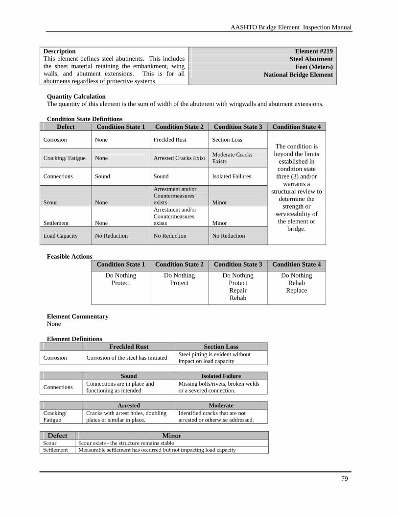
AASHTO Bridge Element Inspection Manual
79
Element #219
Steel Abutment Feet (Meters)
Description This element defines steel abutments. This includes the sheet material retaining the embankment, wing walls, and abutment extensions. This is for all abutments regardless of protective systems.
National Bridge Element
Quantity Calculation The quantity of this element is the sum of width of the abutment with wingwalls and abutment extensions. Condition State Definitions
Defect Condition State 1 Condition State 2 Condition State 3 Condition State 4
Corrosion None Freckled Rust Section Loss
Cracking/ Fatigue None Arrested Cracks Exist Moderate Cracks Exists
Connections Sound Sound Isolated Failures
Scour None
Arrestment and/or Countermeasures exists Minor
Settlement None
Arrestment and/or Countermeasures exists Minor
Load Capacity No Reduction No Reduction No Reduction
The condition is beyond the limits
established in condition state three (3) and/or
warrants a structural review to
determine the strength or
serviceability of the element or
bridge.
Feasible Actions
Condition State 1 Condition State 2 Condition State 3 Condition State 4 Do Nothing
Protect Do Nothing
Protect Do Nothing
Protect Repair Rehab
Do Nothing Rehab
Replace
Element Commentary None Element Definitions
Freckled Rust Section Loss
Corrosion Corrosion of the steel has initiated Steel pitting is evident without impact on load capacity
Sound Isolated Failure
Connections Connections are in place and functioning as intended
Missing bolts/rivets, broken welds or a severed connection.
Arrested Moderate
Cracking/ Fatigue
Cracks with arrest holes, doubling plates or similar in place.
Identified cracks that are not arrested or otherwise addressed.
Defect Minor
Scour Scour exists - the structure remains stable Settlement Measurable settlement has occurred but not impacting load capacity

AASHTO Bridge Element Inspection Manual
80
3.1.11 Submerged Pile/Caps/Footings
Submerged elements are defined as only those elements that are continuously submerged and are visible for inspection.
Designed Configuration ofthe Bent
NewElements
Bent after Scour
New Elements are2 Submerged Piles,Submerged Pile Cap
Elements Below Ground
Ground Line
Elements Above Ground
Bent after Construction andin Service
Water Surface
Submerged Pile
Pile Extention
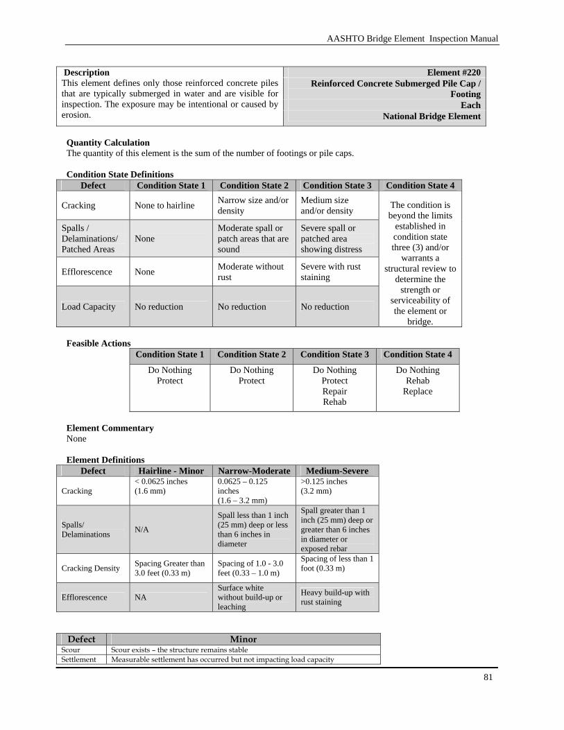
AASHTO Bridge Element Inspection Manual
81
Element #220
Reinforced Concrete Submerged Pile Cap / Footing
Each
Description This element defines only those reinforced concrete piles that are typically submerged in water and are visible for inspection. The exposure may be intentional or caused by erosion. National Bridge Element
Quantity Calculation The quantity of this element is the sum of the number of footings or pile caps. Condition State Definitions
Defect Condition State 1 Condition State 2 Condition State 3 Condition State 4
Cracking None to hairline Narrow size and/or density
Medium size and/or density
Spalls / Delaminations/ Patched Areas
None Moderate spall or patch areas that are sound
Severe spall or patched area showing distress
Efflorescence None Moderate without rust
Severe with rust staining
Load Capacity No reduction No reduction No reduction
The condition is beyond the limits
established in condition state three (3) and/or
warrants a structural review to
determine the strength or
serviceability of the element or
bridge. Feasible Actions
Condition State 1 Condition State 2 Condition State 3 Condition State 4
Do Nothing Protect
Do Nothing Protect
Do Nothing Protect Repair Rehab
Do Nothing Rehab
Replace
Element Commentary None Element Definitions
Defect Hairline - Minor Narrow-Moderate Medium-Severe
Cracking < 0.0625 inches (1.6 mm)
0.0625 – 0.125 inches (1.6 – 3.2 mm)
>0.125 inches (3.2 mm)
Spalls/ Delaminations N/A
Spall less than 1 inch (25 mm) deep or less than 6 inches in diameter
Spall greater than 1 inch (25 mm) deep or greater than 6 inches in diameter or exposed rebar
Cracking Density Spacing Greater than 3.0 feet (0.33 m)
Spacing of 1.0 - 3.0 feet (0.33 – 1.0 m)
Spacing of less than 1 foot (0.33 m)
Efflorescence NA Surface white without build-up or leaching
Heavy build-up with rust staining
Defect Minor
Scour Scour exists – the structure remains stable Settlement Measurable settlement has occurred but not impacting load capacity

AASHTO Bridge Element Inspection Manual
82
Element #225 Steel Submerged Pile Each National Bridge Element
Description This element defines only those steel piles that are continuously submerged in water and are visible for inspection. Piles exposed from erosion or are part of the diver inspection are included in this element. This element is for all pile extensions regardless of protective system.
Quantity Calculation The quantity for this element is the sum of the number of submerged piles. Condition State Definitions
Defect Condition State 1 Condition State 2 Condition State 3 Condition State 4
Corrosion None Freckled Rust Section Loss
Cracking/ Fatigue None Arrested Cracks Exist Moderate Cracks Exists
Connections Sound Sound Isolated Failures
Scour None
Arrestment and/or Countermeasures exists Minor
Settlement None
Arrestment and/or Countermeasures exists Minor
Load Capacity No Reduction No Reduction No Reduction
The condition is beyond the limits
established in condition state three (3) and/or
warrants a structural review to
determine the strength or
serviceability of the element or
bridge.
Feasible Actions
Condition State 1 Condition State 2 Condition State 3 Condition State 4 Do Nothing
Protect Do Nothing
Protect Do Nothing
Protect Repair Rehab
Do Nothing Rehab
Replace
Element Commentary None Element Definitions
Freckled Rust Section Loss Corrosion Corrosion of the steel has initiated Steel pitting is evident without impact
on load capacity
Sound Isolated Failure
Connections Connections are in place and functioning as intended
Missing bolts/rivets, broken welds or a severed connection.
Arrested Moderate
Cracking/ Fatigue
Cracks with arrest holes, doubling plates or similar in place.
Identified cracks that are not arrested or otherwise addressed.
Defect Minor
Scour Scour exists – the structure remains stable Settlement Measurable settlement has occurred but not impacting load capacity
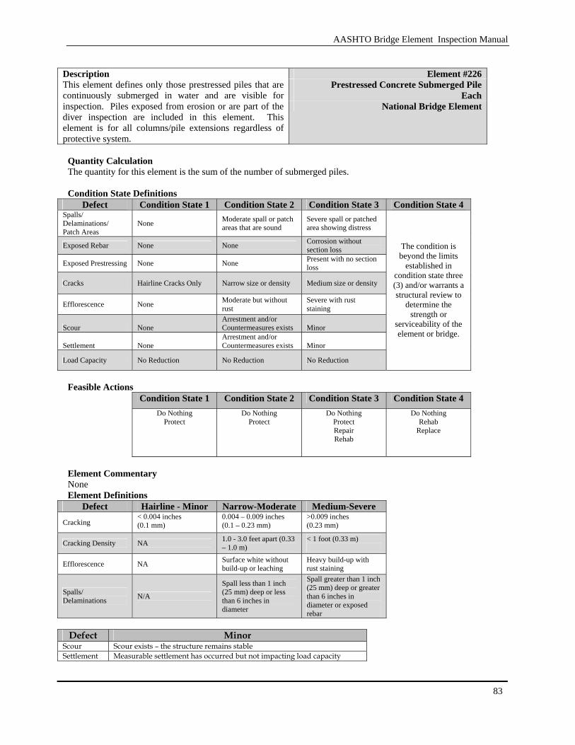
AASHTO Bridge Element Inspection Manual
83
Element #226
Prestressed Concrete Submerged Pile Each
Description This element defines only those prestressed piles that are continuously submerged in water and are visible for inspection. Piles exposed from erosion or are part of the diver inspection are included in this element. This element is for all columns/pile extensions regardless of protective system.
National Bridge Element
Quantity Calculation The quantity for this element is the sum of the number of submerged piles. Condition State Definitions
Defect Condition State 1 Condition State 2 Condition State 3 Condition State 4 Spalls/ Delaminations/ Patch Areas
None Moderate spall or patch areas that are sound
Severe spall or patched area showing distress
Exposed Rebar None None Corrosion without section loss
Exposed Prestressing None None Present with no section loss
Cracks Hairline Cracks Only Narrow size or density Medium size or density
Efflorescence None Moderate but without rust
Severe with rust staining
Scour None Arrestment and/or Countermeasures exists Minor
Settlement None Arrestment and/or Countermeasures exists Minor
Load Capacity No Reduction No Reduction No Reduction
The condition is beyond the limits
established in condition state three (3) and/or warrants a structural review to
determine the strength or
serviceability of the element or bridge.
Feasible Actions
Condition State 1 Condition State 2 Condition State 3 Condition State 4 Do Nothing
Protect Do Nothing
Protect Do Nothing
Protect Repair Rehab
Do Nothing Rehab
Replace
Element Commentary None Element Definitions
Defect Hairline - Minor Narrow-Moderate Medium-Severe Cracking
< 0.004 inches (0.1 mm)
0.004 – 0.009 inches (0.1 – 0.23 mm)
>0.009 inches (0.23 mm)
Cracking Density NA 1.0 - 3.0 feet apart (0.33 – 1.0 m)
< 1 foot (0.33 m)
Efflorescence NA Surface white without build-up or leaching
Heavy build-up with rust staining
Spalls/ Delaminations N/A
Spall less than 1 inch (25 mm) deep or less than 6 inches in diameter
Spall greater than 1 inch (25 mm) deep or greater than 6 inches in diameter or exposed rebar
Defect Minor
Scour Scour exists – the structure remains stable Settlement Measurable settlement has occurred but not impacting load capacity
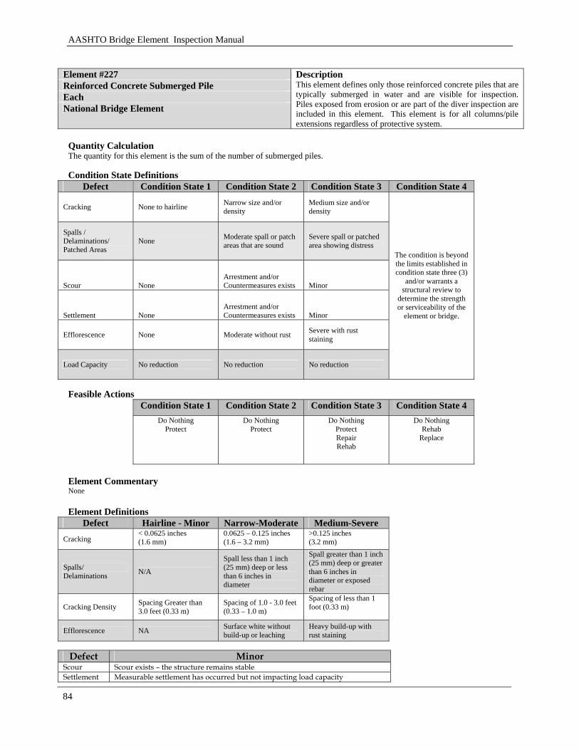
AASHTO Bridge Element Inspection Manual
84
Element #227 Reinforced Concrete Submerged Pile Each National Bridge Element
Description This element defines only those reinforced concrete piles that are typically submerged in water and are visible for inspection. Piles exposed from erosion or are part of the diver inspection are included in this element. This element is for all columns/pile extensions regardless of protective system.
Quantity Calculation The quantity for this element is the sum of the number of submerged piles. Condition State Definitions
Defect Condition State 1 Condition State 2 Condition State 3 Condition State 4
Cracking None to hairline Narrow size and/or density
Medium size and/or density
Spalls / Delaminations/ Patched Areas
None Moderate spall or patch areas that are sound
Severe spall or patched area showing distress
Scour None Arrestment and/or Countermeasures exists Minor
Settlement None Arrestment and/or Countermeasures exists Minor
Efflorescence None Moderate without rust Severe with rust staining
Load Capacity No reduction No reduction No reduction
The condition is beyond the limits established in condition state three (3)
and/or warrants a structural review to
determine the strength or serviceability of the
element or bridge.
Feasible Actions
Condition State 1 Condition State 2 Condition State 3 Condition State 4 Do Nothing
Protect Do Nothing
Protect Do Nothing
Protect Repair Rehab
Do Nothing Rehab
Replace
Element Commentary None Element Definitions
Defect Hairline - Minor Narrow-Moderate Medium-Severe Cracking
< 0.0625 inches (1.6 mm)
0.0625 – 0.125 inches (1.6 – 3.2 mm)
>0.125 inches (3.2 mm)
Spalls/ Delaminations N/A
Spall less than 1 inch (25 mm) deep or less than 6 inches in diameter
Spall greater than 1 inch (25 mm) deep or greater than 6 inches in diameter or exposed rebar
Cracking Density Spacing Greater than 3.0 feet (0.33 m)
Spacing of 1.0 - 3.0 feet (0.33 – 1.0 m)
Spacing of less than 1 foot (0.33 m)
Efflorescence NA Surface white without build-up or leaching
Heavy build-up with rust staining
Defect Minor
Scour Scour exists – the structure remains stable Settlement Measurable settlement has occurred but not impacting load capacity
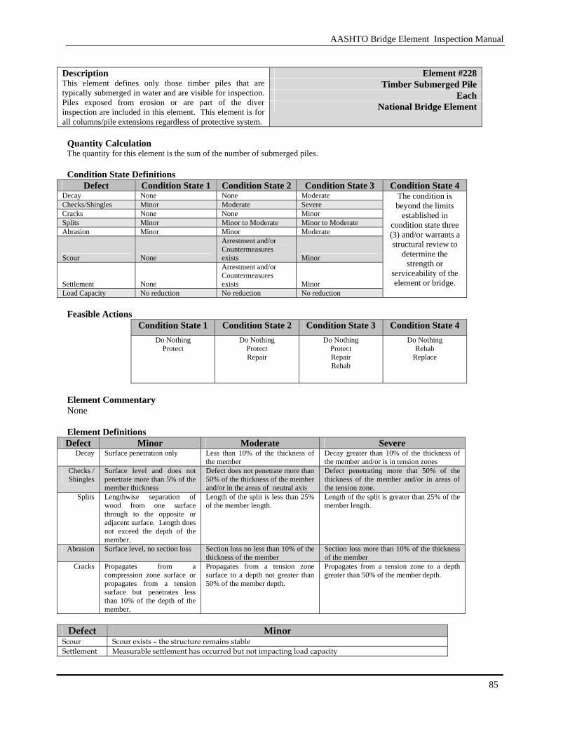
AASHTO Bridge Element Inspection Manual
85
Element #228
Timber Submerged Pile Each
Description This element defines only those timber piles that are typically submerged in water and are visible for inspection. Piles exposed from erosion or are part of the diver inspection are included in this element. This element is for all columns/pile extensions regardless of protective system.
National Bridge Element
Quantity Calculation The quantity for this element is the sum of the number of submerged piles. Condition State Definitions
Defect Condition State 1 Condition State 2 Condition State 3 Condition State 4 Decay None None Moderate Checks/Shingles Minor Moderate Severe Cracks None None Minor Splits Minor Minor to Moderate Minor to Moderate Abrasion Minor Minor Moderate
Scour None
Arrestment and/or Countermeasures exists Minor
Settlement None
Arrestment and/or Countermeasures exists Minor
Load Capacity No reduction No reduction No reduction
The condition is beyond the limits
established in condition state three (3) and/or warrants a structural review to
determine the strength or
serviceability of the element or bridge.
Feasible Actions
Condition State 1 Condition State 2 Condition State 3 Condition State 4
Do Nothing Protect
Do Nothing Protect Repair
Do Nothing Protect Repair Rehab
Do Nothing Rehab
Replace
Element Commentary None Element Definitions Defect Minor Moderate Severe
Decay Surface penetration only Less than 10% of the thickness of the member
Decay greater than 10% of the thickness of the member and/or is in tension zones
Checks / Shingles
Surface level and does not penetrate more than 5% of the member thickness
Defect does not penetrate more than 50% of the thickness of the member and/or in the areas of neutral axis
Defect penetrating more that 50% of the thickness of the member and/or in areas of the tension zone.
Splits Lengthwise separation of wood from one surface through to the opposite or adjacent surface. Length does not exceed the depth of the member.
Length of the split is less than 25% of the member length.
Length of the split is greater than 25% of the member length.
Abrasion Surface level, no section loss Section loss no less than 10% of the thickness of the member
Section loss more than 10% of the thickness of the member
Cracks Propagates from a compression zone surface or propagates from a tension surface but penetrates less than 10% of the depth of the member.
Propagates from a tension zone surface to a depth not greater than 50% of the member depth.
Propagates from a tension zone to a depth greater than 50% of the member depth.
Defect Minor
Scour Scour exists – the structure remains stable Settlement Measurable settlement has occurred but not impacting load capacity

AASHTO Bridge Element Inspection Manual
86
Element #231 Steel Pier Cap Feet (Meters) National Bridge Element
Description This element defines those steel pier caps that support girders and transfer load into piles. This element is for all steel pier caps regardless of protective system.
Quantity Calculation The quantity for this element is the sum of the cap lengths measured along the skew angle. Condition State Definitions
Defect Condition State 1 Condition State 2 Condition State 3 Condition State 4
Corrosion None Freckled Rust Section Loss
Cracking/ Fatigue None Arrested Cracks Exist Moderate Cracks Exists
Connections Sound Sound Isolated Failures
Load Capacity No Reduction No Reduction No Reduction
The condition is beyond the limits
established in condition state three (3) and/or
warrants a structural review to
determine the strength or
serviceability of the element or
bridge. Feasible Actions
Condition State 1 Condition State 2 Condition State 3 Condition State 4
Do Nothing Protect
Do Nothing Protect
Do Nothing Protect Repair Rehab
Do Nothing Rehab
Replace
Element Commentary None Element Definitions
Freckled Rust Section Loss
Corrosion Corrosion of the steel has initiated Steel pitting is evident without impact on load capacity
Sound Isolated Failure
Connections Connections are in place and functioning as intended
Missing bolts/rivets, broken welds or a severed connection.
Arrested Moderate
Cracking/ Fatigue
Cracks with arrest holes, doubling plates or similar in place.
Identified cracks that are not arrested or otherwise addressed.
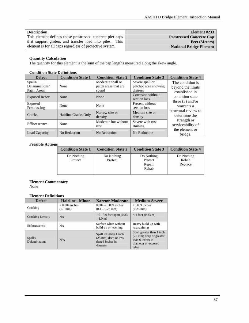
AASHTO Bridge Element Inspection Manual
87
Element #233
Prestressed Concrete Cap Feet (Meters)
Description This element defines those prestressed concrete pier caps that support girders and transfer load into piles. This element is for all caps regardless of protective system. National Bridge Element
Quantity Calculation The quantity for this element is the sum of the cap lengths measured along the skew angle. Condition State Definitions
Defect Condition State 1 Condition State 2 Condition State 3 Condition State 4 Spalls/ Delaminations/ Patch Areas
None Moderate spall or patch areas that are sound
Severe spall or patched area showing distress
Exposed Rebar None None Corrosion without section loss
Exposed Prestressing None None Present without
section loss
Cracks Hairline Cracks Only Narrow size or density
Medium size or density
Efflorescence None Moderate but without rust
Severe with rust staining
Load Capacity No Reduction No Reduction No Reduction
The condition is beyond the limits
established in condition state three (3) and/or
warrants a structural review to
determine the strength or
serviceability of the element or
bridge. Feasible Actions
Condition State 1 Condition State 2 Condition State 3 Condition State 4
Do Nothing Protect
Do Nothing Protect
Do Nothing Protect Repair Rehab
Do Nothing Rehab
Replace
Element Commentary None Element Definitions
Defect Hairline - Minor Narrow-Moderate Medium-Severe Cracking
< 0.004 inches (0.1 mm)
0.004 – 0.009 inches (0.1 – 0.23 mm)
>0.009 inches (0.23 mm)
Cracking Density NA 1.0 - 3.0 feet apart (0.33 – 1.0 m)
< 1 foot (0.33 m)
Efflorescence NA Surface white without build-up or leaching
Heavy build-up with rust staining
Spalls/ Delaminations N/A
Spall less than 1 inch (25 mm) deep or less than 6 inches in diameter
Spall greater than 1 inch (25 mm) deep or greater than 6 inches in diameter or exposed rebar
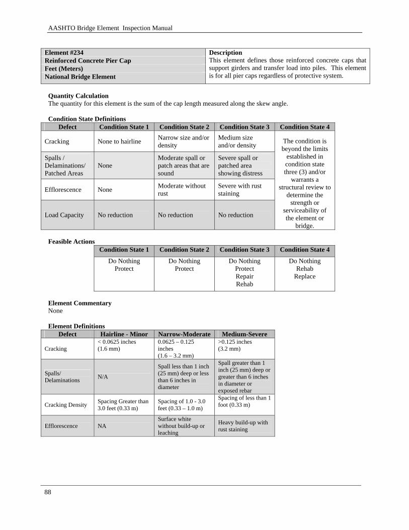
AASHTO Bridge Element Inspection Manual
88
Element #234 Reinforced Concrete Pier Cap Feet (Meters) National Bridge Element
Description This element defines those reinforced concrete caps that support girders and transfer load into piles. This element is for all pier caps regardless of protective system.
Quantity Calculation The quantity for this element is the sum of the cap length measured along the skew angle. Condition State Definitions
Defect Condition State 1 Condition State 2 Condition State 3 Condition State 4
Cracking None to hairline Narrow size and/or density
Medium size and/or density
Spalls / Delaminations/ Patched Areas
None Moderate spall or patch areas that are sound
Severe spall or patched area showing distress
Efflorescence None Moderate without rust
Severe with rust staining
Load Capacity No reduction No reduction No reduction
The condition is beyond the limits
established in condition state three (3) and/or
warrants a structural review to
determine the strength or
serviceability of the element or
bridge. Feasible Actions
Condition State 1 Condition State 2 Condition State 3 Condition State 4 Do Nothing
Protect Do Nothing
Protect Do Nothing
Protect Repair Rehab
Do Nothing Rehab
Replace
Element Commentary None Element Definitions
Defect Hairline - Minor Narrow-Moderate Medium-Severe
Cracking < 0.0625 inches (1.6 mm)
0.0625 – 0.125 inches (1.6 – 3.2 mm)
>0.125 inches (3.2 mm)
Spalls/ Delaminations N/A
Spall less than 1 inch (25 mm) deep or less than 6 inches in diameter
Spall greater than 1 inch (25 mm) deep or greater than 6 inches in diameter or exposed rebar
Cracking Density Spacing Greater than 3.0 feet (0.33 m)
Spacing of 1.0 - 3.0 feet (0.33 – 1.0 m)
Spacing of less than 1 foot (0.33 m)
Efflorescence NA Surface white without build-up or leaching
Heavy build-up with rust staining
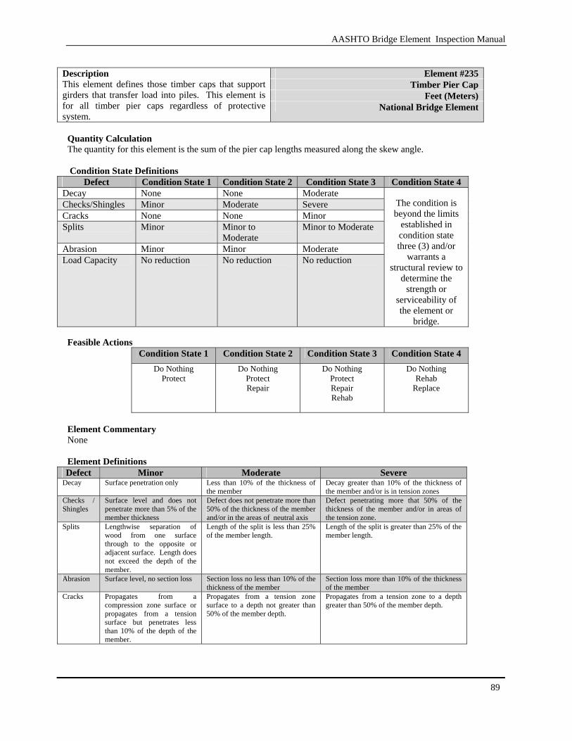
AASHTO Bridge Element Inspection Manual
89
Element #235
Timber Pier Cap Feet (Meters)
Description This element defines those timber caps that support girders that transfer load into piles. This element is for all timber pier caps regardless of protective system.
National Bridge Element
Quantity Calculation The quantity for this element is the sum of the pier cap lengths measured along the skew angle. Condition State Definitions
Defect Condition State 1 Condition State 2 Condition State 3 Condition State 4 Decay None None Moderate Checks/Shingles Minor Moderate Severe Cracks None None Minor Splits Minor Minor to
Moderate Minor to Moderate
Abrasion Minor Minor Moderate Load Capacity No reduction No reduction No reduction
The condition is beyond the limits
established in condition state three (3) and/or
warrants a structural review to
determine the strength or
serviceability of the element or
bridge. Feasible Actions
Condition State 1 Condition State 2 Condition State 3 Condition State 4 Do Nothing
Protect
Do Nothing Protect Repair
Do Nothing Protect Repair Rehab
Do Nothing Rehab
Replace
Element Commentary None Element Definitions Defect Minor Moderate Severe
Decay Surface penetration only Less than 10% of the thickness of the member
Decay greater than 10% of the thickness of the member and/or is in tension zones
Checks / Shingles
Surface level and does not penetrate more than 5% of the member thickness
Defect does not penetrate more than 50% of the thickness of the member and/or in the areas of neutral axis
Defect penetrating more that 50% of the thickness of the member and/or in areas of the tension zone.
Splits Lengthwise separation of wood from one surface through to the opposite or adjacent surface. Length does not exceed the depth of the member.
Length of the split is less than 25% of the member length.
Length of the split is greater than 25% of the member length.
Abrasion Surface level, no section loss Section loss no less than 10% of the thickness of the member
Section loss more than 10% of the thickness of the member
Cracks Propagates from a compression zone surface or propagates from a tension surface but penetrates less than 10% of the depth of the member.
Propagates from a tension zone surface to a depth not greater than 50% of the member depth.
Propagates from a tension zone to a depth greater than 50% of the member depth.
AASHTO Bridge Element Inspection Manual
90
3.1.12 Culverts
This section covers steel, reinforced concrete, timber, masonry and other types of culverts.
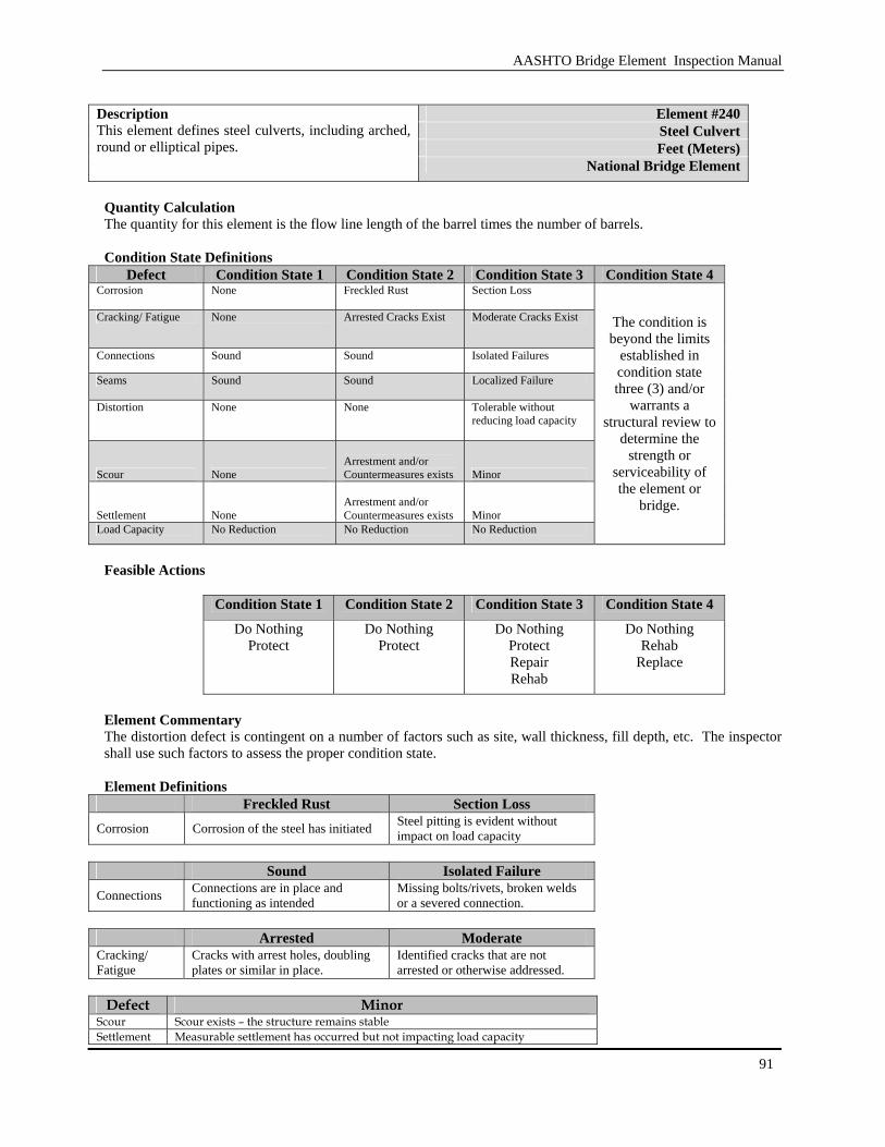
AASHTO Bridge Element Inspection Manual
91
Element #240 Steel Culvert Feet (Meters)
Description This element defines steel culverts, including arched, round or elliptical pipes.
National Bridge Element
Quantity Calculation The quantity for this element is the flow line length of the barrel times the number of barrels. Condition State Definitions
Defect Condition State 1 Condition State 2 Condition State 3 Condition State 4 Corrosion None Freckled Rust Section Loss
Cracking/ Fatigue None Arrested Cracks Exist Moderate Cracks Exist
Connections Sound Sound Isolated Failures
Seams Sound Sound Localized Failure
Distortion None None Tolerable without reducing load capacity
Scour None Arrestment and/or Countermeasures exists Minor
Settlement None Arrestment and/or Countermeasures exists Minor
Load Capacity No Reduction No Reduction No Reduction
The condition is beyond the limits
established in condition state three (3) and/or
warrants a structural review to
determine the strength or
serviceability of the element or
bridge.
Feasible Actions
Condition State 1 Condition State 2 Condition State 3 Condition State 4 Do Nothing
Protect Do Nothing
Protect Do Nothing
Protect Repair Rehab
Do Nothing Rehab
Replace
Element Commentary The distortion defect is contingent on a number of factors such as site, wall thickness, fill depth, etc. The inspector shall use such factors to assess the proper condition state. Element Definitions
Freckled Rust Section Loss
Corrosion Corrosion of the steel has initiated Steel pitting is evident without impact on load capacity
Sound Isolated Failure
Connections Connections are in place and functioning as intended
Missing bolts/rivets, broken welds or a severed connection.
Arrested Moderate
Cracking/ Fatigue
Cracks with arrest holes, doubling plates or similar in place.
Identified cracks that are not arrested or otherwise addressed.
Defect Minor
Scour Scour exists – the structure remains stable Settlement Measurable settlement has occurred but not impacting load capacity
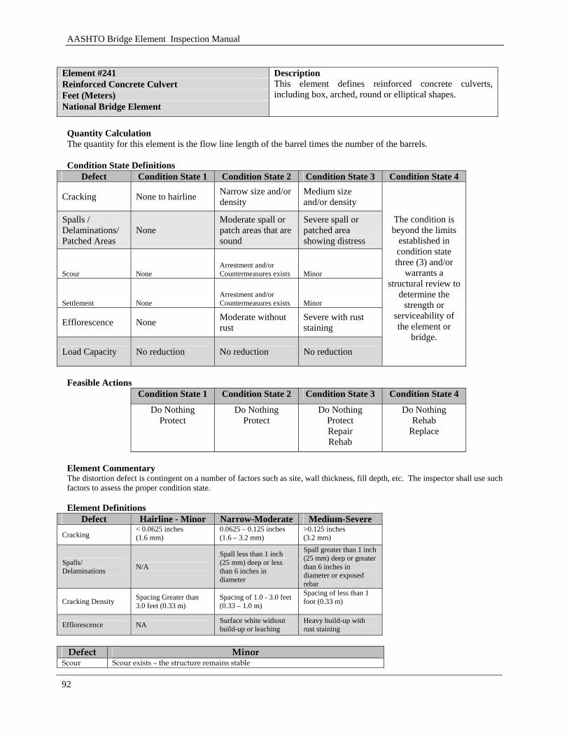
AASHTO Bridge Element Inspection Manual
92
Element #241 Reinforced Concrete Culvert Feet (Meters) National Bridge Element
Description This element defines reinforced concrete culverts, including box, arched, round or elliptical shapes.
Quantity Calculation The quantity for this element is the flow line length of the barrel times the number of the barrels. Condition State Definitions
Defect Condition State 1 Condition State 2 Condition State 3 Condition State 4
Cracking None to hairline Narrow size and/or density
Medium size and/or density
Spalls / Delaminations/ Patched Areas
None Moderate spall or patch areas that are sound
Severe spall or patched area showing distress
Scour None Arrestment and/or Countermeasures exists Minor
Settlement None Arrestment and/or Countermeasures exists Minor
Efflorescence None Moderate without rust
Severe with rust staining
Load Capacity No reduction No reduction No reduction
The condition is beyond the limits
established in condition state three (3) and/or
warrants a structural review to
determine the strength or
serviceability of the element or
bridge.
Feasible Actions
Condition State 1 Condition State 2 Condition State 3 Condition State 4 Do Nothing
Protect Do Nothing
Protect Do Nothing
Protect Repair Rehab
Do Nothing Rehab
Replace
Element Commentary The distortion defect is contingent on a number of factors such as site, wall thickness, fill depth, etc. The inspector shall use such factors to assess the proper condition state. Element Definitions
Defect Hairline - Minor Narrow-Moderate Medium-Severe Cracking
< 0.0625 inches (1.6 mm)
0.0625 – 0.125 inches (1.6 – 3.2 mm)
>0.125 inches (3.2 mm)
Spalls/ Delaminations N/A
Spall less than 1 inch (25 mm) deep or less than 6 inches in diameter
Spall greater than 1 inch (25 mm) deep or greater than 6 inches in diameter or exposed rebar
Cracking Density Spacing Greater than 3.0 feet (0.33 m)
Spacing of 1.0 - 3.0 feet (0.33 – 1.0 m)
Spacing of less than 1 foot (0.33 m)
Efflorescence NA Surface white without build-up or leaching
Heavy build-up with rust staining
Defect Minor
Scour Scour exists – the structure remains stable
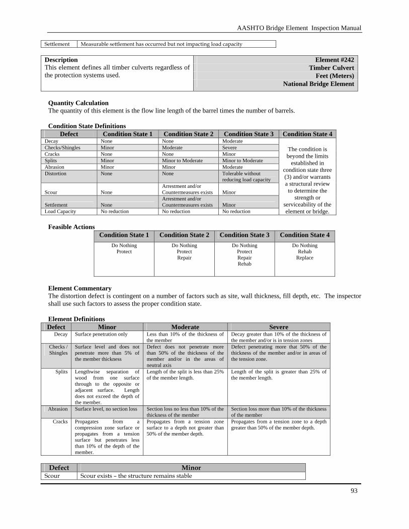
AASHTO Bridge Element Inspection Manual
93
Settlement Measurable settlement has occurred but not impacting load capacity
Element #242 Timber Culvert
Feet (Meters)
Description This element defines all timber culverts regardless of the protection systems used.
National Bridge Element
Quantity Calculation The quantity of this element is the flow line length of the barrel times the number of barrels. Condition State Definitions
Defect Condition State 1 Condition State 2 Condition State 3 Condition State 4 Decay None None Moderate Checks/Shingles Minor Moderate Severe Cracks None None Minor Splits Minor Minor to Moderate Minor to Moderate Abrasion Minor Minor Moderate Distortion None None Tolerable without
reducing load capacity
Scour None Arrestment and/or Countermeasures exists Minor
Settlement None Arrestment and/or Countermeasures exists Minor
Load Capacity No reduction No reduction No reduction
The condition is beyond the limits
established in condition state three (3) and/or warrants a structural review to determine the
strength or serviceability of the element or bridge.
Feasible Actions
Condition State 1 Condition State 2 Condition State 3 Condition State 4
Do Nothing Protect
Do Nothing Protect Repair
Do Nothing Protect Repair Rehab
Do Nothing Rehab
Replace
Element Commentary The distortion defect is contingent on a number of factors such as site, wall thickness, fill depth, etc. The inspector shall use such factors to assess the proper condition state. Element Definitions Defect Minor Moderate Severe
Decay Surface penetration only Less than 10% of the thickness of the member
Decay greater than 10% of the thickness of the member and/or is in tension zones
Checks / Shingles
Surface level and does not penetrate more than 5% of the member thickness
Defect does not penetrate more than 50% of the thickness of the member and/or in the areas of neutral axis
Defect penetrating more that 50% of the thickness of the member and/or in areas of the tension zone.
Splits Lengthwise separation of wood from one surface through to the opposite or adjacent surface. Length does not exceed the depth of the member.
Length of the split is less than 25% of the member length.
Length of the split is greater than 25% of the member length.
Abrasion Surface level, no section loss Section loss no less than 10% of the thickness of the member
Section loss more than 10% of the thickness of the member
Cracks Propagates from a compression zone surface or propagates from a tension surface but penetrates less than 10% of the depth of the member.
Propagates from a tension zone surface to a depth not greater than 50% of the member depth.
Propagates from a tension zone to a depth greater than 50% of the member depth.
Defect Minor
Scour Scour exists – the structure remains stable
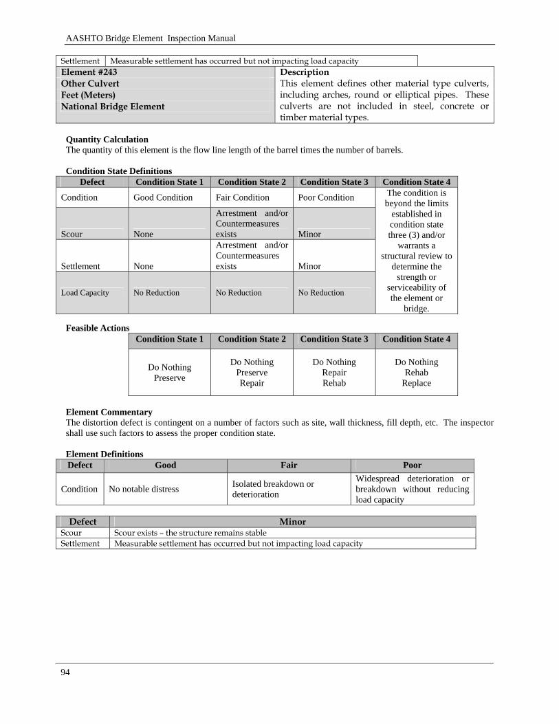
AASHTO Bridge Element Inspection Manual
94
Settlement Measurable settlement has occurred but not impacting load capacity Element #243 Other Culvert Feet (Meters) National Bridge Element
Description This element defines other material type culverts, including arches, round or elliptical pipes. These culverts are not included in steel, concrete or timber material types.
Quantity Calculation The quantity of this element is the flow line length of the barrel times the number of barrels. Condition State Definitions
Defect Condition State 1 Condition State 2 Condition State 3 Condition State 4
Condition Good Condition Fair Condition Poor Condition
Scour None
Arrestment and/or Countermeasures exists Minor
Settlement None
Arrestment and/or Countermeasures exists Minor
Load Capacity No Reduction No Reduction No Reduction
The condition is beyond the limits
established in condition state three (3) and/or
warrants a structural review to
determine the strength or
serviceability of the element or
bridge. Feasible Actions
Condition State 1 Condition State 2 Condition State 3 Condition State 4
Do Nothing Preserve
Do Nothing Preserve Repair
Do Nothing Repair Rehab
Do Nothing Rehab
Replace
Element Commentary The distortion defect is contingent on a number of factors such as site, wall thickness, fill depth, etc. The inspector shall use such factors to assess the proper condition state. Element Definitions Defect Good Fair Poor
Condition No notable distress Isolated breakdown or deterioration
Widespread deterioration or breakdown without reducing load capacity
Defect Minor
Scour Scour exists – the structure remains stable Settlement Measurable settlement has occurred but not impacting load capacity
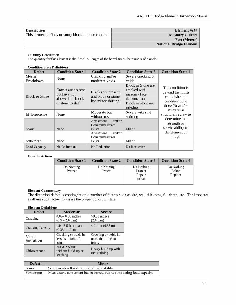
AASHTO Bridge Element Inspection Manual
95
Element #244
Masonry Culvert Feet (Meters)
Description This element defines masonry block or stone culverts.
National Bridge Element
Quantity Calculation The quantity for this element is the flow line length of the barrel times the number of barrels. Condition State Definitions
Defect Condition State 1 Condition State 2 Condition State 3 Condition State 4 Mortar Breakdown None Cracking and/or
moderate voids Severe cracking or voids
Block or Stone
Cracks are present but have not allowed the block or stone to shift
Cracks are present and block or stone has minor shifting
Block or Stone are cracked with masonry face deformation. Block or stone are missing
Efflorescence None Moderate but without rust
Severe with rust staining
Scour None
Arrestment and/or Countermeasures exists Minor
Settlement None
Arrestment and/or Countermeasures exists Minor
Load Capacity No Reduction No Reduction No Reduction
The condition is beyond the limits
established in condition state three (3) and/or
warrants a structural review to
determine the strength or
serviceability of the element or
bridge.
Feasible Actions
Condition State 1 Condition State 2 Condition State 3 Condition State 4
Do Nothing Protect
Do Nothing Protect
Do Nothing Protect Repair Rehab
Do Nothing Rehab
Replace
Element Commentary The distortion defect is contingent on a number of factors such as site, wall thickness, fill depth, etc. The inspector shall use such factors to assess the proper condition state. Element Definitions
Defect Moderate Severe
Cracking 0.02– 0.08 inches (0.5 – 2.0 mm)
>0.08 inches (2.0 mm)
Cracking Density 1.0 - 3.0 feet apart (0.33 – 1.0 m)
< 1 foot (0.33 m)
Mortar Breakdown
Cracking or voids in less than 10% of joints
Cracking or voids in more than 10% of joints
Efflorescence Surface white without build-up or leaching
Heavy build-up with rust staining
Defect Minor
Scour Scour exists – the structure remains stable Settlement Measurable settlement has occurred but not impacting load capacity
AASHTO Bridge Element Inspection Manual
96
AASHTO Bridge Element Inspection Manual
97
3.1.13 Bearings
This section covers fixed, movable and specialty bearing.

AASHTO Bridge Element Inspection Manual
98
Element #310
Elastomeric Bearing Each (Each)
Description This element defines only those bridge bearings that are constructed primarily of elastomers, with or without fabric or metal reinforcement. National Bridge Element
Quantity Calculation The quantity is the sum of each bearing of this type. Condition State Definitions
Defect Condition State 1 Condition State 2 Condition State 3 Condition State 4 Movement Free to Move Minor Restriction Restricted
Alignment Good Tolerable Approaching Limits
Condition No bulging, splitting or tearing
Minor Bulging, splitting or tearing
Moderate bulging, splitting or tearing
Capacity No Reduction No Reduction Some Reduction
The condition is beyond the limits
established in condition state three (3) and/or
warrants a structural review to
determine the strength or
serviceability of the element or
bridge. Feasible Actions
Condition State 1 Condition State 2 Condition State 3 Condition State 4
Do Nothing
Do Nothing Repair
Do Nothing Repair Rehab
Do Nothing Rehab
Replace Element Commentary None Element Definitions Defect Minor Moderate Severe
Alignment Minor lateral or vertical alignment changes are present.
The lateral or vertical alignment is noticeable and approaching the limits of the bearing.
Alignment changes have resulted in bearings that are no longer capable of carrying load or are causing damage to supporting material.

AASHTO Bridge Element Inspection Manual
99
Element #311 Moveable Bearing Each (Each) National Bridge Element
Description This element defines only those bridge bearings which provide for both rotation and longitudinal movement by means of roller, rocker, or sliding mechanisms.
Quantity Calculation The quantity is the sum of each bearing of this type. Condition State Definitions
Defect Condition State 1 Condition State 2 Condition State 3 Condition State 4 Movement Free to Move Minor Restriction Restricted
Alignment Good Tolerable Approaching Limits
Condition No corrosion Early corrosion Early section loss
Capacity No Reduction No Reduction Some Reduction
The condition is beyond the limits
established in condition state three (3) and/or
warrants a structural review to
determine the strength or
serviceability of the element or
bridge. Feasible Actions
Condition State 1 Condition State 2 Condition State 3 Condition State 4
Do Nothing Do Nothing
Protect
Do Nothing Protect Reset
Do Nothing Reset
Replace Element Commentary None Element Definitions Defect Tolerable Approaching Limits Beyond Limits
Alignment Minor lateral or vertical alignment changes are present.
The lateral or vertical alignment is noticeable and approaching the limits of the bearing.
Alignment changes have resulted in bearings that are no longer capable of carrying load or are causing damage to supporting material.
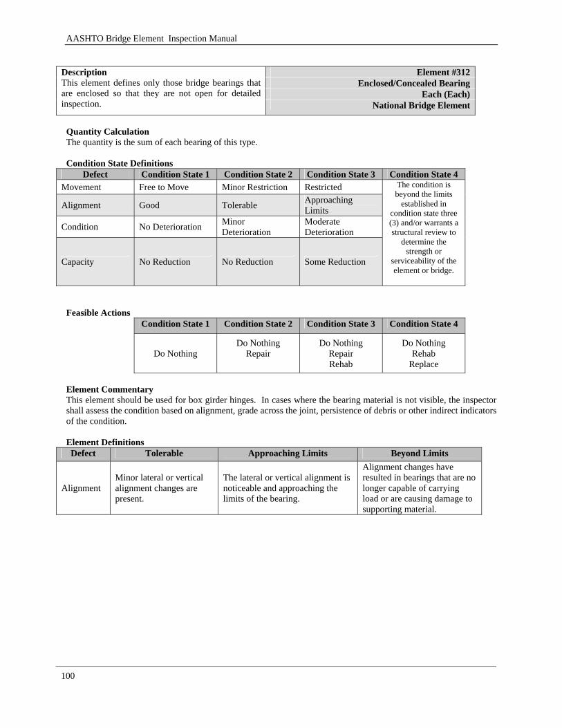
AASHTO Bridge Element Inspection Manual
100
Element #312
Enclosed/Concealed Bearing Each (Each)
Description This element defines only those bridge bearings that are enclosed so that they are not open for detailed inspection. National Bridge Element
Quantity Calculation The quantity is the sum of each bearing of this type. Condition State Definitions
Defect Condition State 1 Condition State 2 Condition State 3 Condition State 4 Movement Free to Move Minor Restriction Restricted
Alignment Good Tolerable Approaching Limits
Condition No Deterioration Minor Deterioration
Moderate Deterioration
Capacity No Reduction No Reduction Some Reduction
The condition is beyond the limits
established in condition state three (3) and/or warrants a structural review to
determine the strength or
serviceability of the element or bridge.
Feasible Actions
Condition State 1 Condition State 2 Condition State 3 Condition State 4
Do Nothing Do Nothing
Repair
Do Nothing Repair Rehab
Do Nothing Rehab
Replace Element Commentary This element should be used for box girder hinges. In cases where the bearing material is not visible, the inspector shall assess the condition based on alignment, grade across the joint, persistence of debris or other indirect indicators of the condition. Element Definitions Defect Tolerable Approaching Limits Beyond Limits
Alignment Minor lateral or vertical alignment changes are present.
The lateral or vertical alignment is noticeable and approaching the limits of the bearing.
Alignment changes have resulted in bearings that are no longer capable of carrying load or are causing damage to supporting material.
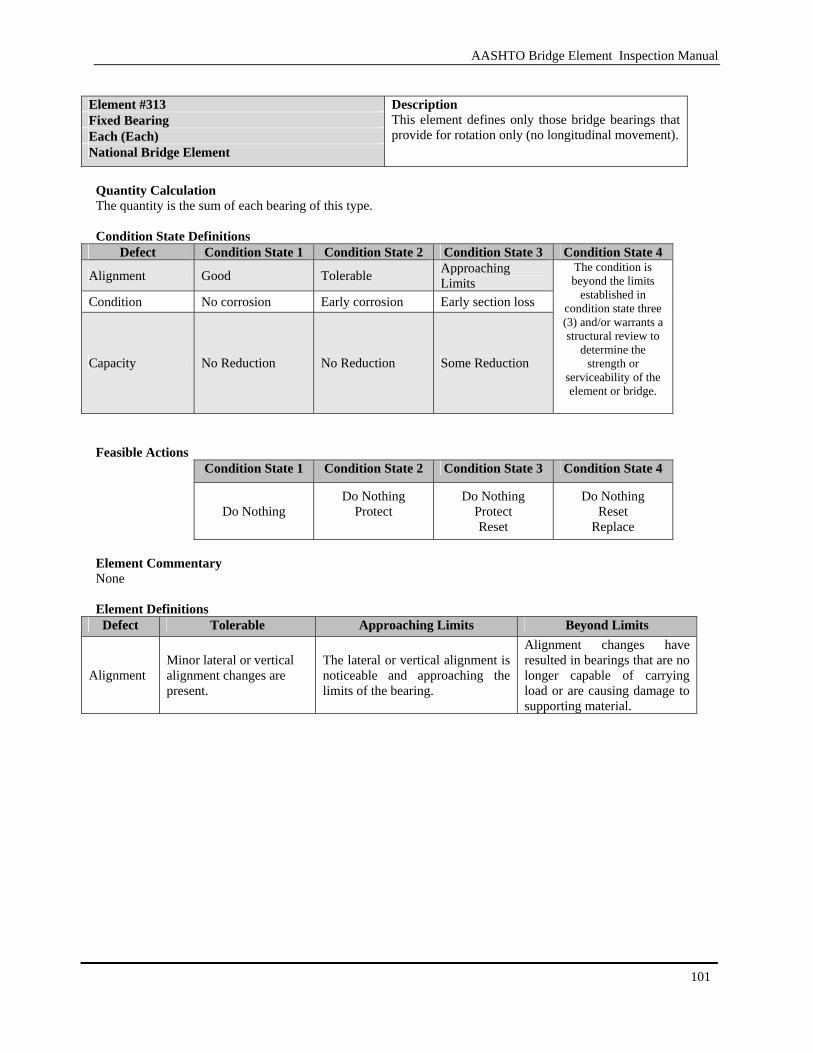
AASHTO Bridge Element Inspection Manual
101
Element #313 Fixed Bearing Each (Each) National Bridge Element
Description This element defines only those bridge bearings that provide for rotation only (no longitudinal movement).
Quantity Calculation The quantity is the sum of each bearing of this type. Condition State Definitions
Defect Condition State 1 Condition State 2 Condition State 3 Condition State 4
Alignment Good Tolerable Approaching Limits
Condition No corrosion Early corrosion Early section loss
Capacity No Reduction No Reduction Some Reduction
The condition is beyond the limits
established in condition state three (3) and/or warrants a structural review to
determine the strength or
serviceability of the element or bridge.
Feasible Actions
Condition State 1 Condition State 2 Condition State 3 Condition State 4
Do Nothing Do Nothing
Protect
Do Nothing Protect Reset
Do Nothing Reset
Replace Element Commentary None Element Definitions Defect Tolerable Approaching Limits Beyond Limits
Alignment Minor lateral or vertical alignment changes are present.
The lateral or vertical alignment is noticeable and approaching the limits of the bearing.
Alignment changes have resulted in bearings that are no longer capable of carrying load or are causing damage to supporting material.
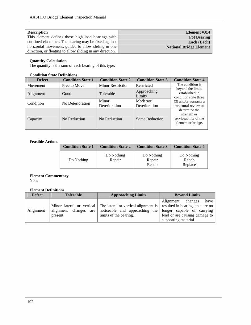
AASHTO Bridge Element Inspection Manual
102
Element #314
Pot Bearing Each (Each)
Description This element defines those high load bearings with confined elastomer. The bearing may be fixed against horizontal movement, guided to allow sliding in one direction, or floating to allow sliding in any direction.
National Bridge Element
Quantity Calculation The quantity is the sum of each bearing of this type. Condition State Definitions
Defect Condition State 1 Condition State 2 Condition State 3 Condition State 4 Movement Free to Move Minor Restriction Restricted
Alignment Good Tolerable Approaching Limits
Condition No Deterioration Minor Deterioration
Moderate Deterioration
Capacity No Reduction No Reduction Some Reduction
The condition is beyond the limits
established in condition state three (3) and/or warrants a structural review to
determine the strength or
serviceability of the element or bridge.
Feasible Actions
Condition State 1 Condition State 2 Condition State 3 Condition State 4
Do Nothing
Do Nothing Repair
Do Nothing Repair Rehab
Do Nothing Rehab
Replace Element Commentary None Element Definitions Defect Tolerable Approaching Limits Beyond Limits
Alignment Minor lateral or vertical alignment changes are present.
The lateral or vertical alignment is noticeable and approaching the limits of the bearing.
Alignment changes have resulted in bearings that are no longer capable of carrying load or are causing damage to supporting material.
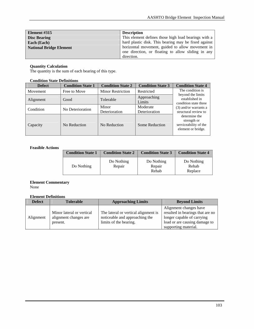
AASHTO Bridge Element Inspection Manual
103
Element #315 Disc Bearing Each (Each) National Bridge Element
Description This element defines those high load bearings with a hard plastic disk. This bearing may be fixed against horizontal movement, guided to allow movement in one direction, or floating to allow sliding in any direction.
Quantity Calculation The quantity is the sum of each bearing of this type. Condition State Definitions
Defect Condition State 1 Condition State 2 Condition State 3 Condition State 4 Movement Free to Move Minor Restriction Restricted
Alignment Good Tolerable Approaching Limits
Condition No Deterioration Minor Deterioration
Moderate Deterioration
Capacity No Reduction No Reduction Some Reduction
The condition is beyond the limits
established in condition state three (3) and/or warrants a structural review to
determine the strength or
serviceability of the element or bridge.
Feasible Actions
Condition State 1 Condition State 2 Condition State 3 Condition State 4
Do Nothing
Do Nothing Repair
Do Nothing Repair Rehab
Do Nothing Rehab
Replace Element Commentary None Element Definitions Defect Tolerable Approaching Limits Beyond Limits
Alignment Minor lateral or vertical alignment changes are present.
The lateral or vertical alignment is noticeable and approaching the limits of the bearing.
Alignment changes have resulted in bearings that are no longer capable of carrying load or are causing damage to supporting material.
AASHTO Bridge Element Inspection Manual
104
3.1.14 Bridge Rail
This section covers bridge rail. These bridge rails can be comprised of steel, concrete, masonry and other materials.

AASHTO Bridge Element Inspection Manual
105
[BLANK PAGE]
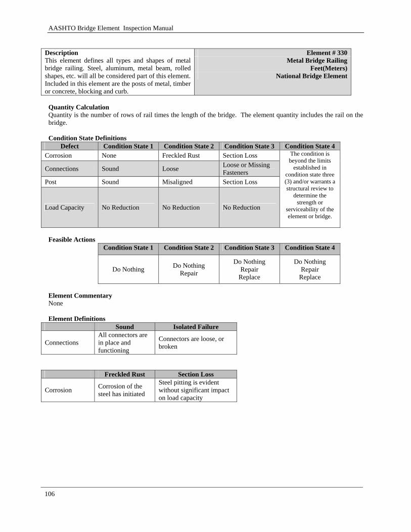
AASHTO Bridge Element Inspection Manual
106
Element # 330
Metal Bridge Railing Feet(Meters)
Description This element defines all types and shapes of metal bridge railing. Steel, aluminum, metal beam, rolled shapes, etc. will all be considered part of this element. Included in this element are the posts of metal, timber or concrete, blocking and curb.
National Bridge Element
Quantity Calculation Quantity is the number of rows of rail times the length of the bridge. The element quantity includes the rail on the bridge. Condition State Definitions
Defect Condition State 1 Condition State 2 Condition State 3 Condition State 4 Corrosion None Freckled Rust Section Loss
Connections Sound Loose Loose or Missing Fasteners
Post Sound Misaligned Section Loss
Load Capacity No Reduction No Reduction No Reduction
The condition is beyond the limits
established in condition state three (3) and/or warrants a structural review to
determine the strength or
serviceability of the element or bridge.
Feasible Actions
Condition State 1 Condition State 2 Condition State 3 Condition State 4
Do Nothing Do Nothing Repair
Do Nothing Repair
Replace
Do Nothing Repair
Replace Element Commentary None Element Definitions
Sound Isolated Failure
Connections All connectors are in place and functioning
Connectors are loose, or broken
Freckled Rust Section Loss
Corrosion Corrosion of the steel has initiated
Steel pitting is evident without significant impact on load capacity
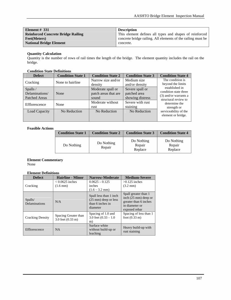
AASHTO Bridge Element Inspection Manual
107
Element # 331 Reinforced Concrete Bridge Railing Feet(Meters) National Bridge Element
Description This element defines all types and shapes of reinforced concrete bridge railing. All elements of the railing must be concrete.
Quantity Calculation Quantity is the number of rows of rail times the length of the bridge. The element quantity includes the rail on the bridge. Condition State Definitions
Defect Condition State 1 Condition State 2 Condition State 3 Condition State 4
Cracking None to hairline Narrow size and/or density
Medium size and/or density
Spalls / Delaminations/ Patched Areas
None Moderate spall or patch areas that are sound
Severe spall or patched area showing distress
Efflorescence None Moderate without rust
Severe with rust staining
Load Capacity No Reduction No Reduction No Reduction
The condition is beyond the limits
established in condition state three (3) and/or warrants a structural review to
determine the strength or
serviceability of the element or bridge.
Feasible Actions
Condition State 1 Condition State 2 Condition State 3 Condition State 4
Do Nothing Do Nothing Repair
Do Nothing Repair
Replace
Do Nothing Repair
Replace Element Commentary None Element Definitions
Defect Hairline - Minor Narrow-Moderate Medium-Severe
Cracking < 0.0625 inches (1.6 mm)
0.0625 – 0.125 inches (1.6 – 3.2 mm)
>0.125 inches (3.2 mm)
Spalls/ Delaminations N/A
Spall less than 1 inch (25 mm) deep or less than 6 inches in diameter
Spall greater than 1 inch (25 mm) deep or greater than 6 inches in diameter or exposed rebar
Cracking Density Spacing Greater than 3.0 feet (0.33 m)
Spacing of 1.0 and 3.0 feet (0.33 – 1.0 m)
Spacing of less than 1 foot (0.33 m)
Efflorescence NA Surface white without build-up or leaching
Heavy build-up with rust staining
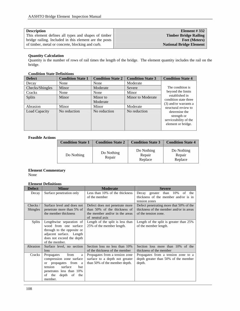
AASHTO Bridge Element Inspection Manual
108
Element # 332
Timber Bridge Railing Feet (Meters)
Description This element defines all types and shapes of timber bridge railing. Included in this element are the posts of timber, metal or concrete, blocking and curb. National Bridge Element
Quantity Calculation Quantity is the number of rows of rail times the length of the bridge. The element quantity includes the rail on the bridge. Condition State Definitions
Defect Condition State 1 Condition State 2 Condition State 3 Condition State 4 Decay None None Moderate Checks/Shingles Minor Moderate Severe Cracks None None Minor Splits Minor Minor to
Moderate Minor to Moderate
Abrasion Minor Minor Moderate Load Capacity No reduction No reduction No reduction
The condition is beyond the limits
established in condition state three (3) and/or warrants a structural review to
determine the strength or
serviceability of the element or bridge.
Feasible Actions
Condition State 1 Condition State 2 Condition State 3 Condition State 4
Do Nothing Do Nothing Repair
Do Nothing Repair
Replace
Do Nothing Repair
Replace Element Commentary None Element Definitions Defect Minor Moderate Severe
Decay Surface penetration only Less than 10% of the thickness of the member
Decay greater than 10% of the thickness of the member and/or is in tension zones
Checks / Shingles
Surface level and does not penetrate more than 5% of the member thickness
Defect does not penetrate more than 50% of the thickness of the member and/or in the areas of neutral axis
Defect penetrating more that 50% of the thickness of the member and/or in areas of the tension zone.
Splits Lengthwise separation of wood from one surface through to the opposite or adjacent surface. Length does not exceed the depth of the member.
Length of the split is less than 25% of the member length.
Length of the split is greater than 25% of the member length.
Abrasion Surface level, no section loss
Section loss no less than 10% of the thickness of the member
Section loss more than 10% of the thickness of the member
Cracks Propagates from a compression zone surface or propagates from a tension surface but penetrates less than 10% of the depth of the member.
Propagates from a tension zone surface to a depth not greater than 50% of the member depth.
Propagates from a tension zone to a depth greater than 50% of the member depth.

AASHTO Bridge Element Inspection Manual
109
Element # 333 Other Bridge Railing Feet(Meters) Bridge Management Element
Description This element defines all types and shapes of bridge railing except those defined as metal, concrete, timber or masonry.
Quantity Calculation Quantity is the number of rows of rail times the length of the bridge. The element quantity includes the rail on the bridge. Condition State Definitions
Defect Condition State 1 Condition State 2 Condition State 3 Condition State 4
Condition Good Condition Fair Condition Poor Condition
The condition is beyond the limits
established in condition state three (3) and/or warrants a structural review to
determine the strength or
serviceability of the element or bridge.
Feasible Actions
Condition State 1 Condition State 2 Condition State 3 Condition State 4
Do Nothing Preserve
Do Nothing Preserve Repair
Do Nothing Repair Rehab
Do Nothing Rehab
Replace
Element Commentary This element should be used for materials not otherwise defined or combinations of materials Element Definitions Defect Good Fair Poor
Condition No notable distress Isolated breakdown or deterioration
Widespread deterioration or breakdown without reducing load capacity
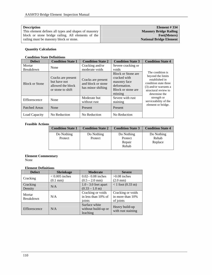
AASHTO Bridge Element Inspection Manual
110
Element # 334
Masonry Bridge Railing Feet(Meters)
Description This element defines all types and shapes of masonry block or stone bridge railing. All elements of the railing must be masonry block or stone. National Bridge Element
Quantity Calculation Condition State Definitions
Defect Condition State 1 Condition State 2 Condition State 3 Condition State 4 Mortar Breakdown None Cracking and/or
moderate voids Severe cracking or voids
Block or Stone
Cracks are present but have not allowed the block or stone to shift
Cracks are present and block or stone has minor shifting
Block or Stone are cracked with masonry face deformation. Block or stone are missing
Efflorescence None Moderate but without rust
Severe with rust staining
Patched Areas None Present Present
Load Capacity No Reduction No Reduction No Reduction
The condition is beyond the limits
established in condition state three (3) and/or warrants a structural review to
determine the strength or
serviceability of the element or bridge.
Feasible Actions
Condition State 1 Condition State 2 Condition State 3 Condition State 4
Do Nothing Protect
Do Nothing Protect
Do Nothing Protect Repair Rehab
Do Nothing Rehab
Replace
Element Commentary None Element Definitions
Defect Shrinkage Moderate Severe
Cracking < 0.005 inches (0.1 mm)
0.02– 0.08 inches (0.5 – 2.0 mm)
>0.08 inches (2.0 mm)
Cracking Density N/A 1.0 - 3.0 feet apart
(0.33 – 1.0 m) < 1 foot (0.33 m)
Mortar Breakdown N/A
Cracking or voids in less than 10% of joints
Cracking or voids in more than 10% of joints
Efflorescence N/A Surface white without build-up or leaching
Heavy build-up with rust staining

AASHTO Bridge Element Inspection Manual
111
[BLANK PAGE]
AASHTO Bridge Element Inspection Manual
112
3.2 Bridge Management Elements
This section describes in detail those other structure elements that agencies have collected to support their Bridge Management System. These elements are defined in fairly generic terms that can be refined by the agency to suit their desired business practices. Agencies can develop additional BME’s as necessary following the agency developed element conventions. When considering additional elements, the agency should consider such factors as element performance, deterioration rates, feasible actions and preservation costs. Appendix A contains guidance on developing elements to facilitate an agency’s business practice.
3.2.1 Joints
This section covers expansion joints, pourable joints, compression joins, and assembly joints

AASHTO Bridge Element Inspection Manual
113
[BLANK PAGE]
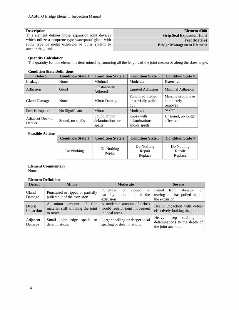
AASHTO Bridge Element Inspection Manual
114
Element #300
Strip Seal Expansion Joint Feet (Meters)
Description This element defines those expansion joint devices which utilize a neoprene type waterproof gland with some type of metal extrusion or other system to anchor the gland.
Bridge Management Element
Quantity Calculation The quantity for this element is determined by summing all the lengths of the joint measured along the skew angle. Condition State Definitions
Defect Condition State 1 Condition State 2 Condition State 3 Condition State 4 Leakage None Minimal Moderate Extensive
Adhesion Good Substantially Adhered Limited Adhesion Minimal Adhesion
Gland Damage None Minor Damage Punctured, ripped or partially pulled out
Missing sections or completely removed
Debris Impaction No Significant Minor Moderate Severe
Adjacent Deck or Header Sound, no spalls
Sound, minor delaminations or spalls
Loose with delaminations and/or spalls
Unsound, no longer effective
Feasible Actions
Condition State 1 Condition State 2 Condition State 3 Condition State 4
Do Nothing Do Nothing Repair
Do Nothing Repair
Replace
Do Nothing Repair
Replace Element Commentary None Element Definitions Defect Minor Moderate Severe
Gland Damage
Punctured or ripped or partially pulled out of the extrusion
Punctured or ripped or partially pulled out of the extrusion
Failed from abrasion or tearing and has pulled out of the extrusion
Debris Impaction
A minor amount of fine material still allowing the joint to move
A moderate amount of debris would restrict joint movement in local areas
Heavy impaction with debris effectively looking the joint.
Adjacent Damage
Small joint edge spalls or delaminations
Larger spalling or deeper local spalling or delaminations
Heavy deep spalling or delaminations to the depth of the joint anchors.
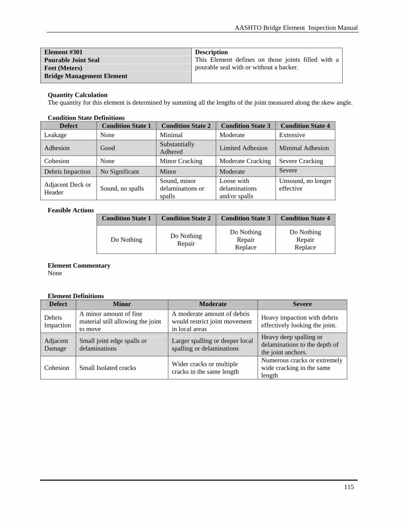
AASHTO Bridge Element Inspection Manual
115
Element #301 Pourable Joint Seal Feet (Meters) Bridge Management Element
Description This Element defines on those joints filled with a pourable seal with or without a backer.
Quantity Calculation The quantity for this element is determined by summing all the lengths of the joint measured along the skew angle. Condition State Definitions
Defect Condition State 1 Condition State 2 Condition State 3 Condition State 4 Leakage None Minimal Moderate Extensive
Adhesion Good Substantially Adhered Limited Adhesion Minimal Adhesion
Cohesion None Minor Cracking Moderate Cracking Severe Cracking Debris Impaction No Significant Minor Moderate Severe
Adjacent Deck or Header Sound, no spalls
Sound, minor delaminations or spalls
Loose with delaminations and/or spalls
Unsound, no longer effective
Feasible Actions
Condition State 1 Condition State 2 Condition State 3 Condition State 4
Do Nothing Do Nothing
Repair
Do Nothing Repair
Replace
Do Nothing Repair
Replace Element Commentary None Element Definitions Defect Minor Moderate Severe
Debris Impaction
A minor amount of fine material still allowing the joint to move
A moderate amount of debris would restrict joint movement in local areas
Heavy impaction with debris effectively looking the joint.
Adjacent Damage
Small joint edge spalls or delaminations
Larger spalling or deeper local spalling or delaminations
Heavy deep spalling or delaminations to the depth of the joint anchors.
Cohesion Small Isolated cracks Wider cracks or multiple cracks in the same length
Numerous cracks or extremely wide cracking in the same length
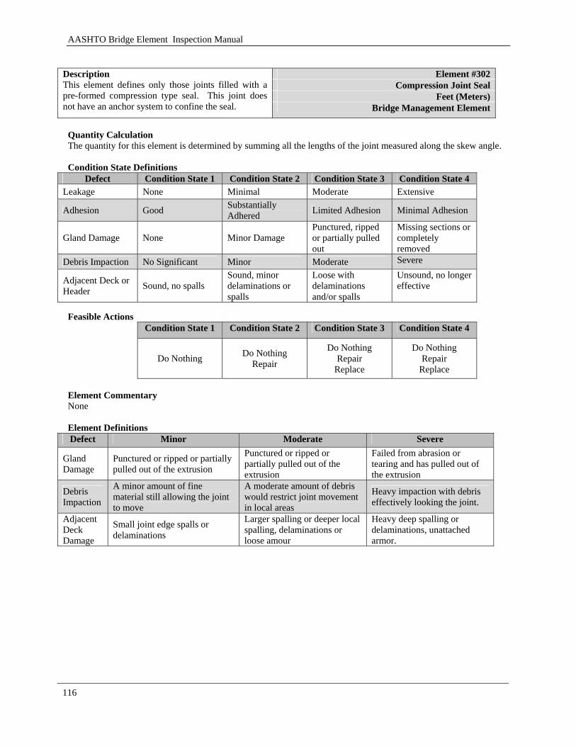
AASHTO Bridge Element Inspection Manual
116
Element #302
Compression Joint Seal Feet (Meters)
Description This element defines only those joints filled with a pre-formed compression type seal. This joint does not have an anchor system to confine the seal. Bridge Management Element
Quantity Calculation The quantity for this element is determined by summing all the lengths of the joint measured along the skew angle. Condition State Definitions
Defect Condition State 1 Condition State 2 Condition State 3 Condition State 4 Leakage None Minimal Moderate Extensive
Adhesion Good Substantially Adhered Limited Adhesion Minimal Adhesion
Gland Damage None Minor Damage Punctured, ripped or partially pulled out
Missing sections or completely removed
Debris Impaction No Significant Minor Moderate Severe
Adjacent Deck or Header Sound, no spalls
Sound, minor delaminations or spalls
Loose with delaminations and/or spalls
Unsound, no longer effective
Feasible Actions
Condition State 1 Condition State 2 Condition State 3 Condition State 4
Do Nothing Do Nothing Repair
Do Nothing Repair
Replace
Do Nothing Repair
Replace Element Commentary None Element Definitions Defect Minor Moderate Severe
Gland Damage
Punctured or ripped or partially pulled out of the extrusion
Punctured or ripped or partially pulled out of the extrusion
Failed from abrasion or tearing and has pulled out of the extrusion
Debris Impaction
A minor amount of fine material still allowing the joint to move
A moderate amount of debris would restrict joint movement in local areas
Heavy impaction with debris effectively looking the joint.
Adjacent Deck Damage
Small joint edge spalls or delaminations
Larger spalling or deeper local spalling, delaminations or loose amour
Heavy deep spalling or delaminations, unattached armor.

AASHTO Bridge Element Inspection Manual
117
Element #303 Assembly Joint With Seal Feet (Meters) Bridge Management Element
Description This element defines only those joints filled with an assembly mechanism that have a seal.
Quantity Calculation The quantity for this element is determined by summing all the lengths of the joint measured along the skew angle. Condition State Definitions
Defect Condition State 1 Condition State 2 Condition State 3 Condition State 4 Leakage None Minimal Moderate Extensive
Adhesion Good Substantially Adhered Limited Adhesion Minimal Adhesion
Gland Damage None Minor Damage Punctured, ripped or partially pulled out
Missing sections or completely removed
Metal Damage None Minor Damage
Isolated Metal Cracking or Broken Connections
Extensive Metal Cracking or Connection Failures.
Debris Impaction No Significant Minor Moderate Severe
Adjacent Deck or Header Sound, no spalls
Sound, minor delaminations or spalls
Loose with delaminations and/or spalls
Unsound, no longer effective
Feasible Actions
Condition State 1 Condition State 2 Condition State 3 Condition State 4
Do Nothing Do Nothing
Repair
Do Nothing Repair
Replace
Do Nothing Repair
Replace Element Commentary None Element Definitions Defect Minor Moderate Severe
Gland Damage Punctured or scraped
Punctured or ripped or partially pulled out of the extrusion
Failed from abrasion or tearing and has pulled out of the extrusion
Debris Impaction
A minor amount of fine material still allowing the joint to move
A moderate amount of debris would restrict joint movement in local areas
Heavy impaction with debris effectively looking the joint.
Adjacent Damage
Small joint edge spalls or delaminations
Larger spalling or deeper local spalling or delaminations
Heavy deep spalling or delaminations to the depth of the joint anchors.
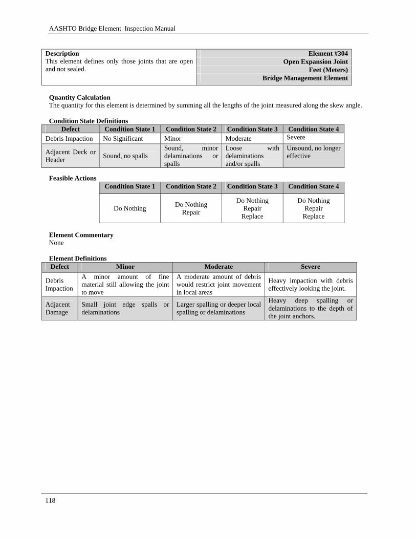
AASHTO Bridge Element Inspection Manual
118
Element #304
Open Expansion Joint Feet (Meters)
Description This element defines only those joints that are open and not sealed.
Bridge Management Element
Quantity Calculation The quantity for this element is determined by summing all the lengths of the joint measured along the skew angle. Condition State Definitions
Defect Condition State 1 Condition State 2 Condition State 3 Condition State 4 Debris Impaction No Significant Minor Moderate Severe
Adjacent Deck or Header Sound, no spalls
Sound, minor delaminations or spalls
Loose with delaminations and/or spalls
Unsound, no longer effective
Feasible Actions
Condition State 1 Condition State 2 Condition State 3 Condition State 4
Do Nothing Do Nothing
Repair
Do Nothing Repair
Replace
Do Nothing Repair
Replace Element Commentary None Element Definitions Defect Minor Moderate Severe
Debris Impaction
A minor amount of fine material still allowing the joint to move
A moderate amount of debris would restrict joint movement in local areas
Heavy impaction with debris effectively looking the joint.
Adjacent Damage
Small joint edge spalls or delaminations
Larger spalling or deeper local spalling or delaminations
Heavy deep spalling or delaminations to the depth of the joint anchors.
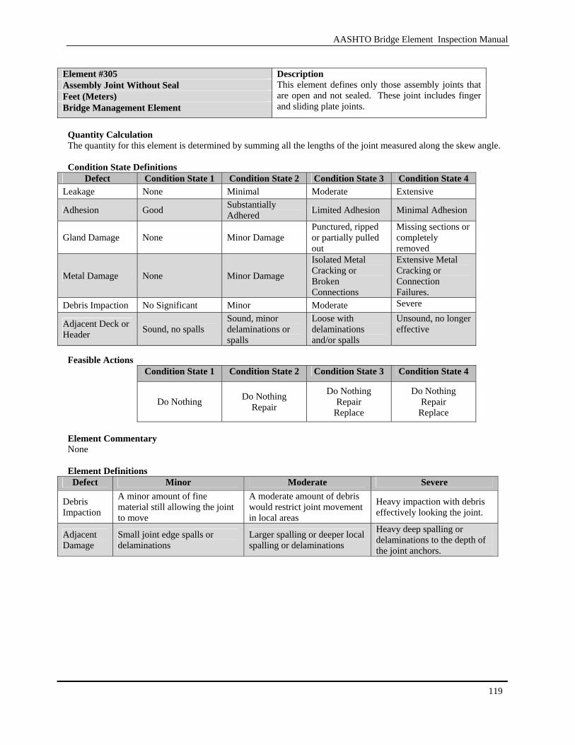
AASHTO Bridge Element Inspection Manual
119
Element #305 Assembly Joint Without Seal Feet (Meters) Bridge Management Element
Description This element defines only those assembly joints that are open and not sealed. These joint includes finger and sliding plate joints.
Quantity Calculation The quantity for this element is determined by summing all the lengths of the joint measured along the skew angle. Condition State Definitions
Defect Condition State 1 Condition State 2 Condition State 3 Condition State 4 Leakage None Minimal Moderate Extensive
Adhesion Good Substantially Adhered Limited Adhesion Minimal Adhesion
Gland Damage None Minor Damage Punctured, ripped or partially pulled out
Missing sections or completely removed
Metal Damage None Minor Damage
Isolated Metal Cracking or Broken Connections
Extensive Metal Cracking or Connection Failures.
Debris Impaction No Significant Minor Moderate Severe
Adjacent Deck or Header Sound, no spalls
Sound, minor delaminations or spalls
Loose with delaminations and/or spalls
Unsound, no longer effective
Feasible Actions
Condition State 1 Condition State 2 Condition State 3 Condition State 4
Do Nothing Do Nothing Repair
Do Nothing Repair
Replace
Do Nothing Repair
Replace Element Commentary None Element Definitions Defect Minor Moderate Severe
Debris Impaction
A minor amount of fine material still allowing the joint to move
A moderate amount of debris would restrict joint movement in local areas
Heavy impaction with debris effectively looking the joint.
Adjacent Damage
Small joint edge spalls or delaminations
Larger spalling or deeper local spalling or delaminations
Heavy deep spalling or delaminations to the depth of the joint anchors.

AASHTO Bridge Element Inspection Manual
120
3.2.2 Approach Slabs
This section will cover bridge approach slabs. These slabs will be constructed with concrete and mild or prestress (post tension) reinforcement.

AASHTO Bridge Element Inspection Manual
121
[BLANK PAGE]
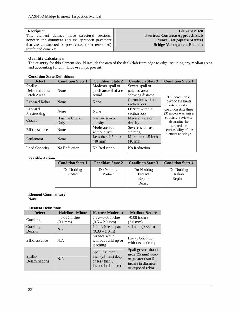
AASHTO Bridge Element Inspection Manual
122
Element # 320
Prestress Concrete Approach Slab Square Feet(Square Meters)
Description This element defines those structural sections, between the abutment and the approach pavement that are constructed of prestressed (post tensioned) reinforced concrete.
Bridge Management Element
Quantity Calculation The quantity for this element should include the area of the deck/slab from edge to edge including any median areas and accounting for any flares or ramps present. Condition State Definitions
Defect Condition State 1 Condition State 2 Condition State 3 Condition State 4 Spalls/ Delaminations/ Patch Areas
None Moderate spall or patch areas that are sound
Severe spall or patched area showing distress
Exposed Rebar None None Corrosion without section loss
Exposed Prestressing None None Present without
section loss
Cracks Hairline Cracks Only
Narrow size or density
Medium size or density
Efflorescence None Moderate but without rust
Severe with rust staining
Settlement None Less than 1.5 inch (40 mm)
More than 1.5 inch (40 mm)
Load Capacity No Reduction No Reduction No Reduction
The condition is beyond the limits
established in condition state three (3) and/or warrants a structural review to
determine the strength or
serviceability of the element or bridge.
Feasible Actions
Condition State 1 Condition State 2 Condition State 3 Condition State 4 Do Nothing
Protect Do Nothing
Protect Do Nothing
Protect Repair Rehab
Do Nothing Rehab
Replace
Element Commentary None Element Definitions
Defect Hairline - Minor Narrow-Moderate Medium-Severe
Cracking < 0.005 inches (0.1 mm)
0.02– 0.08 inches (0.5 – 2.0 mm)
>0.08 inches (2.0 mm)
Cracking Density NA 1.0 - 3.0 feet apart
(0.33 – 1.0 m) < 1 foot (0.33 m)
Efflorescence N/A Surface white without build-up or leaching
Heavy build-up with rust staining
Spalls/ Delaminations N/A
Spall less than 1 inch (25 mm) deep or less than 6 inches in diameter
Spall greater than 1 inch (25 mm) deep or greater than 6 inches in diameter or exposed rebar

AASHTO Bridge Element Inspection Manual
123
Element # 321 Reinforced Concrete Approach Slab Square Feet(Square Meters) Bridge Management Element
Description This Element defines those structural sections, between the abutment and the approach pavement that are constructed of mild steel reinforced concrete.
Quantity Calculation The quantity for this element should include the area of the deck/slab from edge to edge including any median areas and accounting for any flares or ramps present. Condition State Definitions
Defect Condition State 1 Condition State 2 Condition State 3 Condition State 4
Cracking None to minor Narrow size and/or density
Medium size and/or density
Spalls / Delaminations/ Patched Areas
None Moderate spall or patch areas that are sound
Severe spall or patched area showing distress
Efflorescence None Moderate without rust
Severe with rust staining
Settlement None Less than 1.5 inch (40 mm)
More than 1.5 inch (40 mm)
Load Capacity No reduction No reduction No reduction
The condition is beyond the limits
established in condition state three (3) and/or warrants a structural review to
determine the strength or
serviceability of the element or bridge.
Feasible Actions
Condition State 1 Condition State 2 Condition State 3 Condition State 4 Do Nothing
Protect Do Nothing
Protect Repair
Do Nothing Protect Repair Rehab
Do Nothing Rehab
Replace
Element Commentary None Element Definitions
Defect Hairline - Minor Narrow-Moderate Medium-Severe
Cracking < 0.0625 inches (1.6 mm)
0.0625 – 0.125 inches (1.6 – 3.2 mm)
>0.125 inches (3.2 mm)
Spalls/ Delaminations N/A
Spall less than 1 inch (25 mm) deep or less than 6 inches in diameter
Spall greater than 1 inch (25 mm) deep or greater than 6 inches in diameter or exposed rebar
Cracking Density Spacing Greater than 3.0 feet (0.33 m)
Spacing of 1.0 and 3.0 feet (0.33 – 1.0 m)
Spacing of less than 1 foot (0.33 m)
Efflorescence NA Surface white without build-up or leaching
Heavy build-up with rust staining

AASHTO Bridge Element Inspection Manual
124
3.2.3 Smart Flags (Defect Flags)
This section will cover the smart flags and their use. Each flag will be associated with an element and will define the predominate defect for that condition state.

AASHTO Bridge Element Inspection Manual
125
[BLANK PAGE]
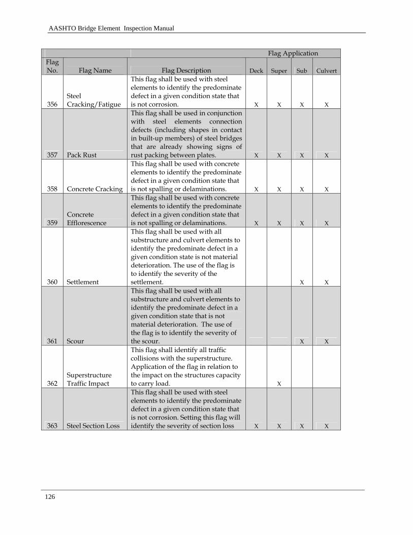
AASHTO Bridge Element Inspection Manual
126
Flag Application Flag No. Flag Name Flag Description Deck Super Sub Culvert
356 Steel Cracking/Fatigue
This flag shall be used with steel elements to identify the predominate defect in a given condition state that is not corrosion. X X X X
357 Pack Rust
This flag shall be used in conjunction with steel elements connection defects (including shapes in contact in built-up members) of steel bridges that are already showing signs of rust packing between plates. X X X X
358 Concrete Cracking
This flag shall be used with concrete elements to identify the predominate defect in a given condition state that is not spalling or delaminations. X X X X
359 Concrete Efflorescence
This flag shall be used with concrete elements to identify the predominate defect in a given condition state that is not spalling or delaminations. X X X X
360 Settlement
This flag shall be used with all substructure and culvert elements to identify the predominate defect in a given condition state is not material deterioration. The use of the flag is to identify the severity of the settlement. X X
361 Scour
This flag shall be used with all substructure and culvert elements to identify the predominate defect in a given condition state that is not material deterioration. The use of the flag is to identify the severity of the scour. X X
362 Superstructure Traffic Impact
This flag shall identify all traffic collisions with the superstructure. Application of the flag in relation to the impact on the structures capacity to carry load. X
363 Steel Section Loss
This flag shall be used with steel elements to identify the predominate defect in a given condition state that is not corrosion. Setting this flag will identify the severity of section loss X X X X
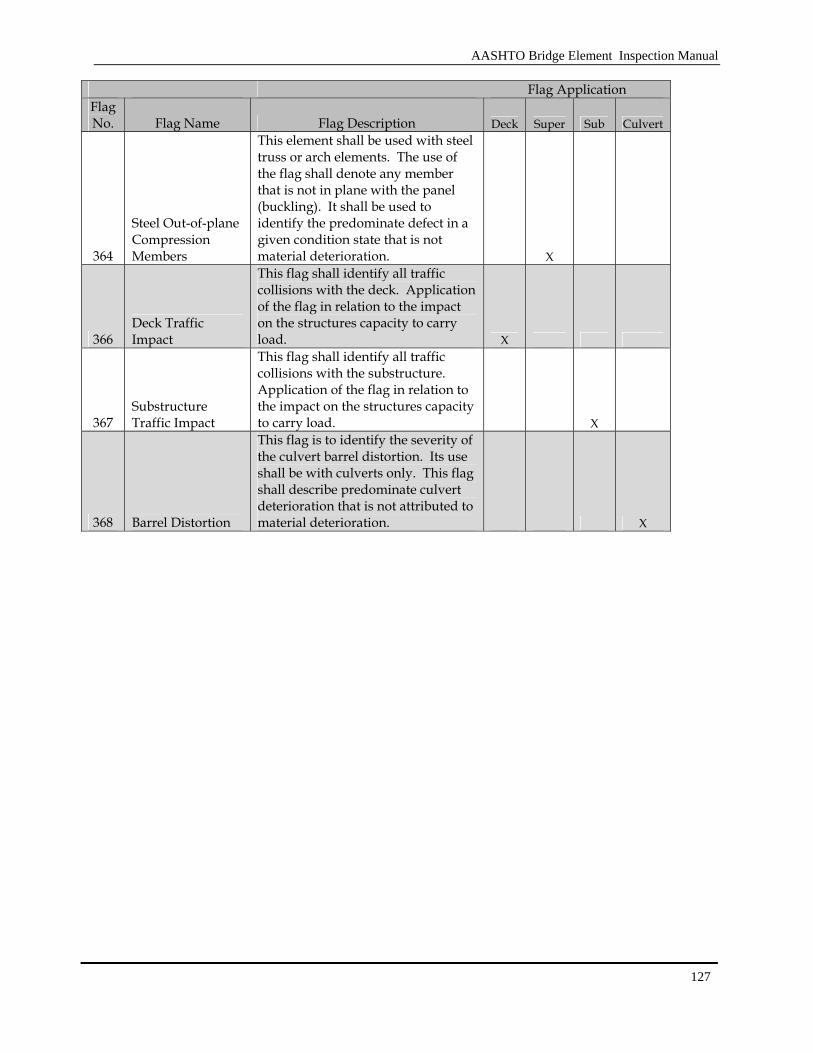
AASHTO Bridge Element Inspection Manual
127
Flag Application Flag No. Flag Name Flag Description Deck Super Sub Culvert
364
Steel Out-of-plane Compression Members
This element shall be used with steel truss or arch elements. The use of the flag shall denote any member that is not in plane with the panel (buckling). It shall be used to identify the predominate defect in a given condition state that is not material deterioration. X
366 Deck Traffic Impact
This flag shall identify all traffic collisions with the deck. Application of the flag in relation to the impact on the structures capacity to carry load. X
367 Substructure Traffic Impact
This flag shall identify all traffic collisions with the substructure. Application of the flag in relation to the impact on the structures capacity to carry load. X
368 Barrel Distortion
This flag is to identify the severity of the culvert barrel distortion. Its use shall be with culverts only. This flag shall describe predominate culvert deterioration that is not attributed to material deterioration. X
AASHTO Bridge Element Inspection Manual
128
3.2.4 Protective Systems
The elements in this section are protective systems types. These systems will influence the deterioration and condition of the underlying structural element. The general categories are wearing surfaces and protective coatings.

AASHTO Bridge Element Inspection Manual
129
[BLANK PAGE]
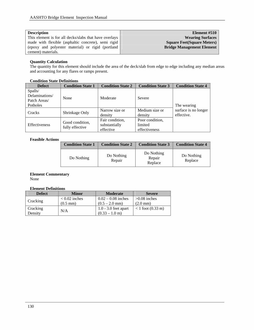
AASHTO Bridge Element Inspection Manual
130
Element #510
Wearing Surfaces Square Feet(Square Meters)
Description This element is for all decks/slabs that have overlays made with flexible (asphaltic concrete), semi rigid (epoxy and polyester material) or rigid (portland cement) materials.
Bridge Management Element
Quantity Calculation The quantity for this element should include the area of the deck/slab from edge to edge including any median areas and accounting for any flares or ramps present. Condition State Definitions
Defect Condition State 1 Condition State 2 Condition State 3 Condition State 4 Spalls/ Delaminations/ Patch Areas/ Potholes
None Moderate Severe
Cracks Shrinkage Only Narrow size or density
Medium size or density
Effectiveness Good condition, fully effective
Fair condition, substantially effective
Poor condition, limited effectiveness
The wearing surface is no longer effective.
Feasible Actions
Condition State 1 Condition State 2 Condition State 3 Condition State 4
Do Nothing Do Nothing Repair
Do Nothing Repair
Replace
Do Nothing Replace
Element Commentary None Element Definitions
Defect Minor Moderate Severe
Cracking < 0.02 inches (0.5 mm)
0.02 – 0.08 inches (0.5 – 2.0 mm)
>0.08 inches (2.0 mm)
Cracking Density N/A 1.0 - 3.0 feet apart
(0.33 – 1.0 m) < 1 foot (0.33 m)
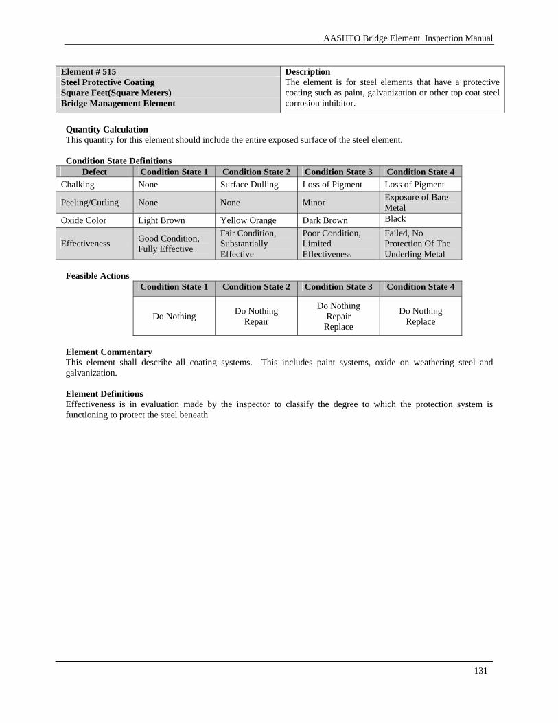
AASHTO Bridge Element Inspection Manual
131
Element # 515 Steel Protective Coating Square Feet(Square Meters) Bridge Management Element
Description The element is for steel elements that have a protective coating such as paint, galvanization or other top coat steel corrosion inhibitor.
Quantity Calculation This quantity for this element should include the entire exposed surface of the steel element. Condition State Definitions
Defect Condition State 1 Condition State 2 Condition State 3 Condition State 4 Chalking None Surface Dulling Loss of Pigment Loss of Pigment
Peeling/Curling None None Minor Exposure of Bare Metal
Oxide Color Light Brown Yellow Orange Dark Brown Black
Effectiveness Good Condition, Fully Effective
Fair Condition, Substantially Effective
Poor Condition, Limited Effectiveness
Failed, No Protection Of The Underling Metal
Feasible Actions
Condition State 1 Condition State 2 Condition State 3 Condition State 4
Do Nothing Do Nothing Repair
Do Nothing Repair
Replace
Do Nothing Replace
Element Commentary This element shall describe all coating systems. This includes paint systems, oxide on weathering steel and galvanization. Element Definitions Effectiveness is in evaluation made by the inspector to classify the degree to which the protection system is functioning to protect the steel beneath

AASHTO Bridge Element Inspection Manual
132
Element # 520
Deck/Slab Protection Systems Square Feet(Square Meters)
Description This element defines all types of protective systems used to protect decks or slabs regardless of the type.
Bridge Management Element
Quantity Calculation This quantity for this element should include the entire exposed surface of the steel element. Condition State Definitions
Defect Condition State 1 Condition State 2 Condition State 3 Condition State 4
Effectiveness Good condition, fully effective
Fair condition, substantially effective
Poor condition, limited effectiveness
The protective system has failed or is non- operational
Feasible Actions
Condition State 1 Condition State 2 Condition State 3 Condition State 4
Do Nothing Do Nothing Repair
Do Nothing Repair
Replace
Do Nothing Replace
Element Commentary The deck/slab protection system element is intended to capture situations where the deck or slab may deteriorate at a rate that is slower than unprotected situations. Protection systems may include rebar coatings, cathodic protection or other similar protection methods. Wearing surfaces should be noted under the appropriate wearing surface element. Element Definitions Effectiveness is in evaluation made by the inspector to classify the degree to which the protection system is functioning.

AASHTO Bridge Element Inspection Manual
133
Element # 521 Concrete Protective Coating Square Feet(Square Meters) Bridge Management Element
Description This element is for concrete elements that have a protective coating applied to them. These coating include silane/siloxane water proofers, crack sealers such as High Molecular Weight Methacrylate (HMWM) or any top coat barrier that protects concrete from deterioration and reinforcing steel from corrosion.
Quantity Calculation This quantity for this element should include the entire exposed surface of the concrete element. Condition State Definitions
Defect Condition State 1 Condition State 2 Condition State 3 Condition State 4
Wear None
Underlying Concrete Not Exposed. Coating Showing Wears From UV Exposure. Friction Course Missing.
Underlying Concrete Is Not Exposed. Thickness Of The Coating Is Reduced.
Underlying Concrete Exposed. Treated Cracks Are Exposed
Effectiveness Good condition, fully effective
Fair condition, substantially effective
Poor condition, limited effectiveness
The protective system has failed or is non- operational
Feasible Actions
Condition State 1 Condition State 2 Condition State 3 Condition State 4
Do Nothing Do Nothing Repair
Do Nothing Repair
Replace
Do Nothing Replace
Element Commentary None Element Definitions Effectiveness is in evaluation made by the inspector to classify the degree to which the protection system is functioning
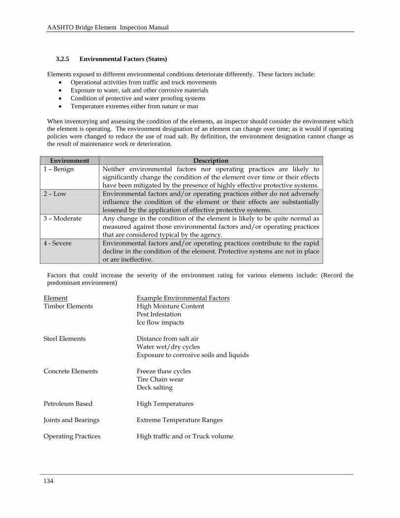
AASHTO Bridge Element Inspection Manual
134
3.2.5 Environmental Factors (States)
Elements exposed to different environmental conditions deteriorate differently. These factors include: • Operational activities from traffic and truck movements • Exposure to water, salt and other corrosive materials • Condition of protective and water proofing systems • Temperature extremes either from nature or man
When inventorying and assessing the condition of the elements, an inspector should consider the environment which the element is operating. The environment designation of an element can change over time; as it would if operating policies were changed to reduce the use of road salt. By definition, the environment designation cannot change as the result of maintenance work or deterioration. Environment Description
1 – Benign Neither environmental factors nor operating practices are likely to significantly change the condition of the element over time or their effects have been mitigated by the presence of highly effective protective systems.
2 – Low Environmental factors and/or operating practices either do not adversely influence the condition of the element or their effects are substantially lessened by the application of effective protective systems.
3 – Moderate Any change in the condition of the element is likely to be quite normal as measured against those environmental factors and/or operating practices that are considered typical by the agency.
4 - Severe Environmental factors and/or operating practices contribute to the rapid decline in the condition of the element. Protective systems are not in place or are ineffective.
Factors that could increase the severity of the environment rating for various elements include: (Record the predominant environment)
Element Example Environmental Factors Timber Elements High Moisture Content
Pest Infestation Ice flow impacts
Steel Elements Distance from salt air Water wet/dry cycles Exposure to corrosive soils and liquids
Concrete Elements Freeze thaw cycles Tire Chain wear Deck salting
Petroleum Based High Temperatures
Joints and Bearings Extreme Temperature Ranges
Operating Practices High traffic and or Truck volume

AASHTO Bridge Element Inspection Manual
135
AASHTO Bridge Element Inspection Manual
136
Appendix
The appendix section will provide guidance on the use of this manual. There are four appendices to aid an agency the development of their data collection process. These appendices are:
A Agency Developed Elements B Inspection Examples C Element Grouping D Element Migration Process
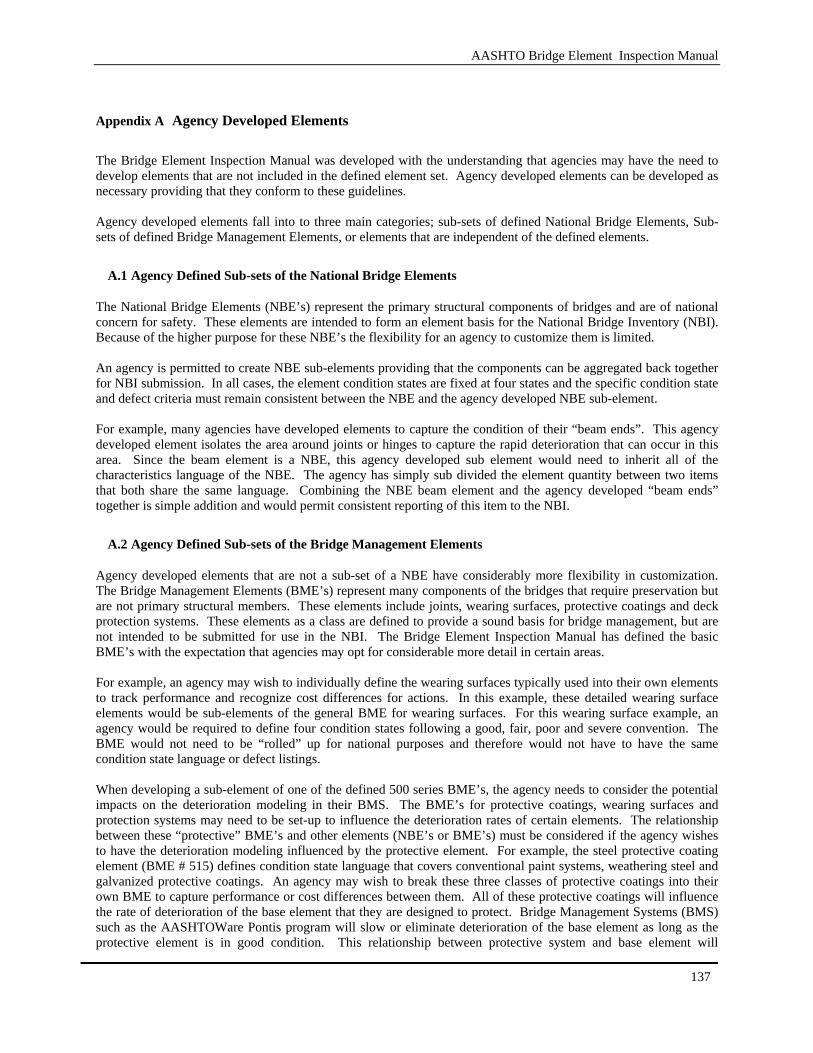
AASHTO Bridge Element Inspection Manual
137
Appendix A Agency Developed Elements
The Bridge Element Inspection Manual was developed with the understanding that agencies may have the need to develop elements that are not included in the defined element set. Agency developed elements can be developed as necessary providing that they conform to these guidelines. Agency developed elements fall into to three main categories; sub-sets of defined National Bridge Elements, Sub-sets of defined Bridge Management Elements, or elements that are independent of the defined elements.
A.1 Agency Defined Sub-sets of the National Bridge Elements
The National Bridge Elements (NBE’s) represent the primary structural components of bridges and are of national concern for safety. These elements are intended to form an element basis for the National Bridge Inventory (NBI). Because of the higher purpose for these NBE’s the flexibility for an agency to customize them is limited. An agency is permitted to create NBE sub-elements providing that the components can be aggregated back together for NBI submission. In all cases, the element condition states are fixed at four states and the specific condition state and defect criteria must remain consistent between the NBE and the agency developed NBE sub-element. For example, many agencies have developed elements to capture the condition of their “beam ends”. This agency developed element isolates the area around joints or hinges to capture the rapid deterioration that can occur in this area. Since the beam element is a NBE, this agency developed sub element would need to inherit all of the characteristics language of the NBE. The agency has simply sub divided the element quantity between two items that both share the same language. Combining the NBE beam element and the agency developed “beam ends” together is simple addition and would permit consistent reporting of this item to the NBI.
A.2 Agency Defined Sub-sets of the Bridge Management Elements
Agency developed elements that are not a sub-set of a NBE have considerably more flexibility in customization. The Bridge Management Elements (BME’s) represent many components of the bridges that require preservation but are not primary structural members. These elements include joints, wearing surfaces, protective coatings and deck protection systems. These elements as a class are defined to provide a sound basis for bridge management, but are not intended to be submitted for use in the NBI. The Bridge Element Inspection Manual has defined the basic BME’s with the expectation that agencies may opt for considerable more detail in certain areas. For example, an agency may wish to individually define the wearing surfaces typically used into their own elements to track performance and recognize cost differences for actions. In this example, these detailed wearing surface elements would be sub-elements of the general BME for wearing surfaces. For this wearing surface example, an agency would be required to define four condition states following a good, fair, poor and severe convention. The BME would not need to be “rolled” up for national purposes and therefore would not have to have the same condition state language or defect listings. When developing a sub-element of one of the defined 500 series BME’s, the agency needs to consider the potential impacts on the deterioration modeling in their BMS. The BME’s for protective coatings, wearing surfaces and protection systems may need to be set-up to influence the deterioration rates of certain elements. The relationship between these “protective” BME’s and other elements (NBE’s or BME’s) must be considered if the agency wishes to have the deterioration modeling influenced by the protective element. For example, the steel protective coating element (BME # 515) defines condition state language that covers conventional paint systems, weathering steel and galvanized protective coatings. An agency may wish to break these three classes of protective coatings into their own BME to capture performance or cost differences between them. All of these protective coatings will influence the rate of deterioration of the base element that they are designed to protect. Bridge Management Systems (BMS) such as the AASHTOWare Pontis program will slow or eliminate deterioration of the base element as long as the protective element is in good condition. This relationship between protective system and base element will

AASHTO Bridge Element Inspection Manual
138
constrain the degree of customization that an agency can exercise on the condition state element definitions of sub-elements to the 500 series of BME’s.
A.3 Independent Agency Developed Elements
Agencies who wish to develop element that are not a sub-set of an NBE or BME may do so as necessary for their business. Elements that are not sub-set of any defined element provide the most flexibility as these elements are not intended to be reported at a national level nor are they expected to be rolled up into any element with defined condition state language in this manual. These elements are available for agencies utilizing bridge management systems to track specific aspects of their inventory or to capture specific performance aspects of bridges. Independent agency developed elements may or may not have defined feasible actions, defined deterioration and need not follow any condition state or defect language included in this manual. These are free form element items that are only limited by the number of required condition states (four). Examples of independent agency developed elements could include; approach guardrail, slope paving, seismic retrofit components, or tunnels just to name a few. These elements may or may not have defined deterioration patterns or feasible actions. Independent agency elements could also be created to track maintenance items that an agency wishes to capture during the inspection process. Items such as the condition of drains, structure lighting, or bridge identification plaques could be developed into elements that are not associated with deterioration but potentially have feasible actions. Independent agency developed elements can also be created to a capture ancillary structure items that an agencies may wish to inspect. These elements can coexist side by side with the bridge elements and can optionally be defined with deterioration models or feasible actions as an agency desires. This provides a readymade framework for capturing items such as tunnels, wall and overhead sign structures within the agencies BMS.
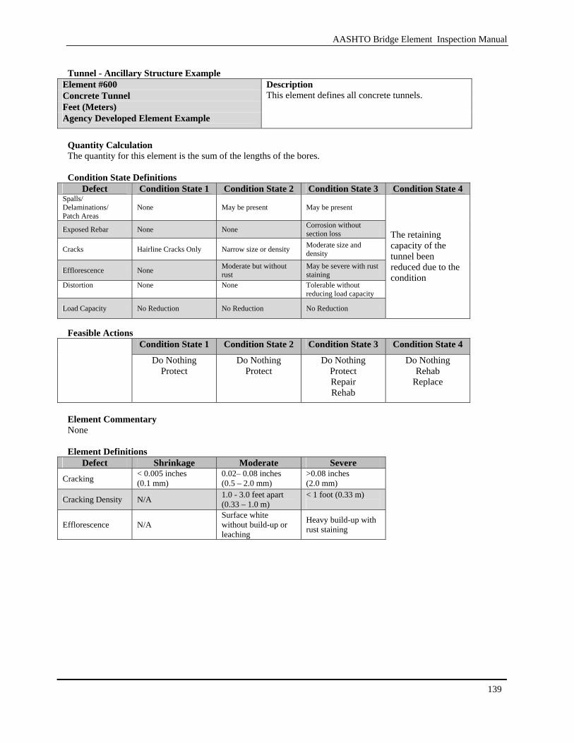
AASHTO Bridge Element Inspection Manual
139
Tunnel - Ancillary Structure Example
Element #600 Concrete Tunnel Feet (Meters) Agency Developed Element Example
Description This element defines all concrete tunnels.
Quantity Calculation The quantity for this element is the sum of the lengths of the bores. Condition State Definitions
Defect Condition State 1 Condition State 2 Condition State 3 Condition State 4 Spalls/ Delaminations/ Patch Areas
None May be present May be present
Exposed Rebar None None Corrosion without section loss
Cracks Hairline Cracks Only Narrow size or density Moderate size and density
Efflorescence None Moderate but without rust
May be severe with rust staining
Distortion None None Tolerable without reducing load capacity
Load Capacity No Reduction No Reduction No Reduction
The retaining capacity of the tunnel been reduced due to the condition
Feasible Actions
Condition State 1 Condition State 2 Condition State 3 Condition State 4 Do Nothing
Protect Do Nothing
Protect Do Nothing
Protect Repair Rehab
Do Nothing Rehab
Replace
Element Commentary None Element Definitions
Defect Shrinkage Moderate Severe
Cracking < 0.005 inches (0.1 mm)
0.02– 0.08 inches (0.5 – 2.0 mm)
>0.08 inches (2.0 mm)
Cracking Density N/A 1.0 - 3.0 feet apart (0.33 – 1.0 m)
< 1 foot (0.33 m)
Efflorescence N/A Surface white without build-up or leaching
Heavy build-up with rust staining

AASHTO Bridge Element Inspection Manual
140
[BLANK PAGE]

AASHTO Bridge Element Inspection Manual
141
Appendix B Inspection Examples
The examples provided are to show the minimal inspection with the National Bridge Elements (NBE) and an in-depth example using the combination of National Bridge Elements and the Bridge Management Elements (BME). The examples will cover concrete, steel and timber.
B.1 Timber Bridge
A two span timber bridge has an out-to-out width of 40 feet (12 meters) and each span is 30 feet (9 meters). The bridge rail is constructed of timbers. The timber deck has a 2 inches (50 millimeters) asphalt cover. The superstructure consists of thirteen girder lines on timber caps and five timber pile bents. The structure has no joints. The length of each wingwall is 10 feet (3 meters). An inspection of the structure shows that the bridge elements are in good condition and has no noticeable defects accept for the deck and pile caps. Deck Elements and Quantities This timber structure was constructed with a deck/girder system. The timber deck is covered by asphalt. The total quantity for this element is (2 span X 30 feet (9 meters) per span X 40 feet (12 meters) wide) or 2,400 Sq Ft (216 Sq M). The rail element on this structure is the timber bridge rail. The quantity for this element is (2 spans X 30 feet (9 meters) X 2 sides) or 120 feet (36 meters). Superstructure Elements and Quantities The primary superstructure element is the open timber girders. The quantity for this element is (2 spans X 30 feet (9 meters) X 13 girders) or 780 feet (234 meters). Substructure Elements and Quantities The remaining elements are all substructure elements. The first element is the timber abutment. This element for timber only covers the back wall and the wingwalls. The quantity for this item is [(2 wingwalls X 10 feet (3 meter) per wingwall+ 40 feet (12 meter) under the roadway) X 2 abutments] or 120 feet (36 meter). The girders are resting on pile caps. There are 3 pile caps (one at each abutment and one at the center bent). This element is the timber pile caps. The quantity for this element is (40 feet (12 meter) per cap X 3 caps) or 120 feet (36 meter). Substructure Elements and Quantities The last items are the piles. These piles were constructed of timber and the inspectable area is above ground level. This element is the timber pile extension. The quantity for this element is (5 per pile cap X 3 pile caps) or 15 each.
Top view – revealing top condition and elements.

AASHTO Bridge Element Inspection Manual
142
Bottom view – revealing underside elements and substructure elements
Cross section – displaying typical section of the bridge with all of the elements.
National Bridge Element List Element Number
Element Description
Unit of Measure
Total Quantity
Condition State 1
Condition State 2
Condition State 3
Condition State 4
31 Timber Deck Sq Ft (sq m)
2,400 100% 0% 0% 0%
111 Timber Girder/Beam
Feet (meter)
780 100% 0% 0% 0%
206 Timber Column/Pile
Extension
Each 15 100% 0% 0% 0%
216 Timber Abutment
Feet (meter)
120 100% 0% 0% 0%
235 Timber Pier Cap
Feet (meter)
120
100% 0% 0% 0%
332 Timber Bridge Railing
Feet (meter)
120 100% 0% 0% 0%
The above list is the minimal list needed to evaluate the structure for condition. Agencies needed additional information should collect these additional elements to support a bridge management system. Bridge Management Element List (including the MBE elements) Element Number
Element Description
Unit of Measure
Total Quantity
Condition State 1
Condition State 2
Condition State 3
Condition State 4
31 Timber Deck Sq Ft (sq m)
2,400 100% 0% 0% 0%
111 Timber Girder/Beam
Feet (meter)
780 100% 0% 0% 0%
206 Timber Column/Pile
Extension
Each 15 100% 0% 0% 0%
216 Timber Abutment
Feet (meter)
120 100% 0% 0% 0%
235 Timber Pier Cap
Feet (meter)
120
100% 0% 0% 0%
332 Timber Bridge Railing
Feet (meter)
120 100% 0% 0% 0%
510 Wearing Surfaces
Sq Ft (sq m)
2,400 100% 0% 0% 0%
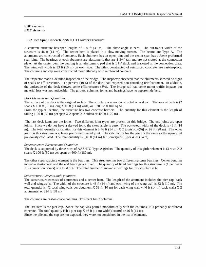
AASHTO Bridge Element Inspection Manual
143
NBE elements BME elements
B.2 Two Span Concrete AASTHTO Girder Structure
A concrete structure has span lengths of 100 ft (30 m). The skew angle is zero. The out-to-out width of the structure is 46 ft (14 m). The center bent is placed in a slow-moving stream. The beams are Type A. The abutments are constructed of concrete. Each abutment has an open joint and the center span has a Jeene preformed seal joint. The bearings at each abutment are elastomeric that are 1 3/4" tall and are not slotted at the connection plate. At the center bent the bearing is an elastomeric pad that is 1 ½" thick and is slotted at the connection plate. The wingwall width is 33 ft (10 m) on each side. The piles, constructed of reinforced concrete, are cast-in-place. The columns and cap were constructed monolithically with reinforced concrete. The inspector made a detailed inspection of the bridge. The inspector observed that the abutments showed no signs of spalls or efflorescence. Ten percent (10%) of the deck had exposed non-corroding reinforcement. In addition, the underside of the deck showed some efflorescence (3%). The bridge rail had some minor traffic impacts but material loss was not noticeable. The girders, columns, joints and bearings have no apparent defects. Deck Elements and Quantities: The surface of the deck is the original surface. The structure was not constructed on a skew. The area of deck is (2 spans X 100 ft (30 m) long X 46 ft (14 m) wide) or 9200 sq ft 840 sq M. From the typical section, the structure has two concrete barriers. The quantity for this element is the length of railing (100 ft (30 m) per span X 2 spans X 2 sides) or 400 ft (120 m). The last deck items are the joints. Two different joint types are present on this bridge. The end joints are open joints. Since we do not have a skewed joint, the skew angle is zero. The out-to-out width of the deck is 46 ft (14 m). The total quantity calculation for this element is [(46 ft (14 m) X 2 joints)/cos(0)] or 92 ft (28 m). The other joint on this structure is a Jeene preformed sealed joint. The calculation for the joint is the same as the open joint previously calculated. The total quantity is [(46 ft (14 m) X 1 joints)/cos(0)] or 46 ft (14 m). Superstructure Elements and Quantities The deck is supported by three rows of AASHTO Type A girders. The quantity of this girder element is (3 rows X 2 spans X 100 ft (30 m) per span) or 600 ft (180 m). The other superstructure element is the bearings. This structure has two different systems bearings. Center bent has movable elastomeric and the end bearings are fixed. The quantity of fixed bearings for this structure is (1 per beam X 2 connection points) or a total of 6. The total number of movable bearings for this structure is 6. Substructure Elements and Quantities The substructure consists of abutments and a center bent. The length of the abutment includes the pier cap, back wall and wingwalls. The width of the structure is 46 ft (14 m) and each wing of the wing wall is 33 ft (10 m). The total quantity is [(2 total wingwalls per abutment X 33 ft (10 m) for each wing wall + 46 ft (14 m) back wall) X 2 abutments] or 224 ft (68 m). The columns are cast-in-place columns. This bent has 2 columns. The last item is the pier cap. Since the cap was poured monolithically with the columns, it is probably reinforced concrete. The total quantity is [(1 pier cap X 46 ft (14 m) width)/cos(0)] or 46 ft (14 m). Since the pile and the cap are not exposed, they were not considered in the list of elements.
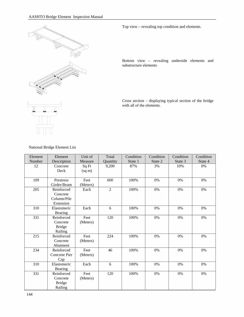
AASHTO Bridge Element Inspection Manual
144
Top view – revealing top condition and elements.
Bottom view – revealing underside elements and substructure elements
Cross section – displaying typical section of the bridge with all of the elements.
National Bridge Element List Element Number
Element Description
Unit of Measure
Total Quantity
Condition State 1
Condition State 2
Condition State 3
Condition State 4
12 Concrete Deck
Sq Ft (sq m)
9,200 87% 3% 10% 0%
109 Prestress Girder/Beam
Feet (Meters)
600 100% 0% 0% 0%
205 Reinforced Concrete
Column/Pile Extension
Each 2 100% 0% 0% 0%
310 Elastomeric Bearing
Each 6 100% 0% 0% 0%
331 Reinforced Concrete Bridge Railing
Feet (Meters)
120 100% 0% 0% 0%
215
Reinforced Concrete Abutment
Feet (Meters)
224 100% 0% 0% 0%
234 Reinforced Concrete Pier
Cap
Feet (Meters)
46 100% 0% 0% 0%
310 Elastomeric Bearing
Each 6 100% 0% 0% 0%
331 Reinforced Concrete Bridge Railing
Feet (Meters)
120 100% 0% 0% 0%
AASHTO Bridge Element Inspection Manual
145
The above list is the minimal list needed to evaluate the structure for condition. Agencies needed additional information should collect these additional elements to support a bridge management system.

AASHTO Bridge Element Inspection Manual
146
Bridge Management Element List (including the BME elements) Element Number
Element Description
Unit of Measure
Total Quantity
Condition State 1
Condition State 2
Condition State 3
Condition State 4
12 Concrete Deck
Sq Ft (sq m)
9,200 87% 3% 10% 0%
109 Prestress Girder/Beam
Feet (Meters)
600 100% 0% 0% 0%
205 Reinforced Concrete
Column/Pile Extension
Each 2 100% 0% 0% 0%
215
Reinforced Concrete Abutment
Feet (Meters)
224 100% 0% 0% 0%
234 Reinforced Concrete Pier
Cap
Feet (Meters)
46 100% 0% 0% 0%
310 Elastomeric Bearing
Each 6 100% 0% 0% 0%
331 Reinforced Concrete Bridge Railing
Feet (Meters)
120 100% 0% 0% 0%
302 Compression Joint Seal
Feet (Meters)
46 100% 0% 0% 0%
304
Open Expansion
Joint
Feet (Meters)
92 100% 0% 0% 0%
NBE elements BME elements
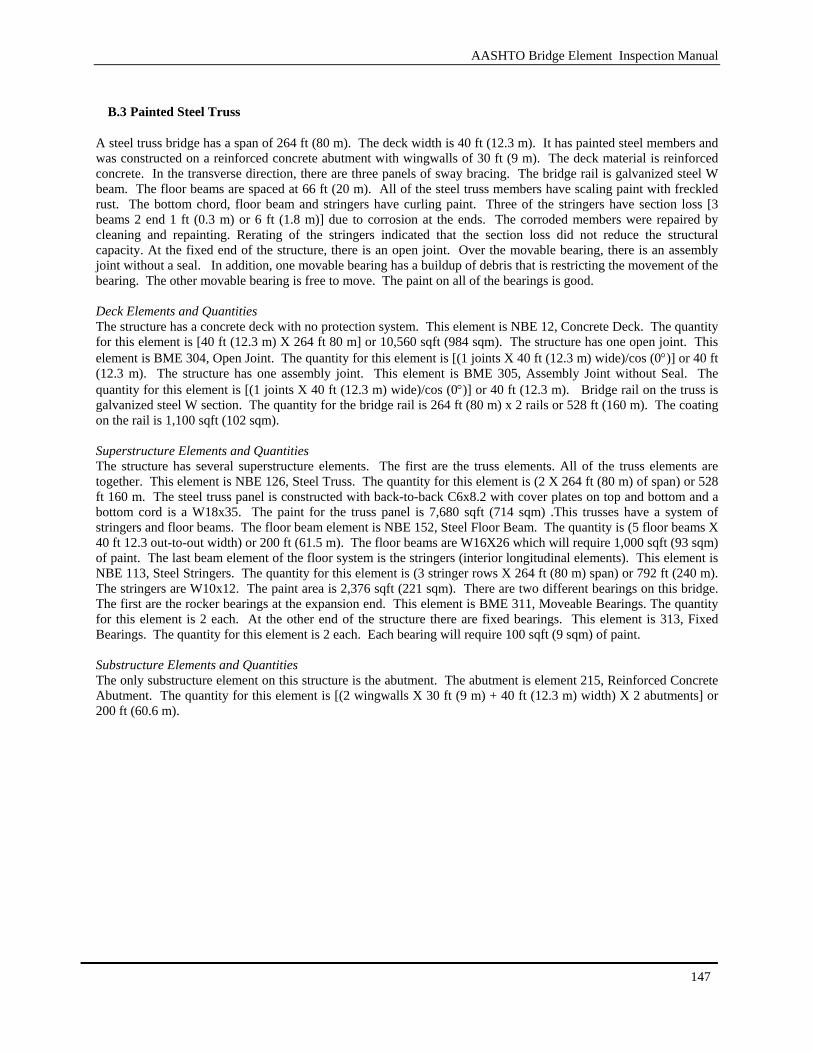
AASHTO Bridge Element Inspection Manual
147
B.3 Painted Steel Truss
A steel truss bridge has a span of 264 ft (80 m). The deck width is 40 ft (12.3 m). It has painted steel members and was constructed on a reinforced concrete abutment with wingwalls of 30 ft (9 m). The deck material is reinforced concrete. In the transverse direction, there are three panels of sway bracing. The bridge rail is galvanized steel W beam. The floor beams are spaced at 66 ft (20 m). All of the steel truss members have scaling paint with freckled rust. The bottom chord, floor beam and stringers have curling paint. Three of the stringers have section loss [3 beams 2 end 1 ft (0.3 m) or 6 ft (1.8 m)] due to corrosion at the ends. The corroded members were repaired by cleaning and repainting. Rerating of the stringers indicated that the section loss did not reduce the structural capacity. At the fixed end of the structure, there is an open joint. Over the movable bearing, there is an assembly joint without a seal. In addition, one movable bearing has a buildup of debris that is restricting the movement of the bearing. The other movable bearing is free to move. The paint on all of the bearings is good. Deck Elements and Quantities The structure has a concrete deck with no protection system. This element is NBE 12, Concrete Deck. The quantity for this element is [40 ft (12.3 m) X 264 ft 80 m] or 10,560 sqft (984 sqm). The structure has one open joint. This element is BME 304, Open Joint. The quantity for this element is [(1 joints X 40 ft (12.3 m) wide)/cos (0°)] or 40 ft (12.3 m). The structure has one assembly joint. This element is BME 305, Assembly Joint without Seal. The quantity for this element is [(1 joints X 40 ft (12.3 m) wide)/cos (0°)] or 40 ft (12.3 m). Bridge rail on the truss is galvanized steel W section. The quantity for the bridge rail is 264 ft (80 m) x 2 rails or 528 ft (160 m). The coating on the rail is 1,100 sqft (102 sqm). Superstructure Elements and Quantities The structure has several superstructure elements. The first are the truss elements. All of the truss elements are together. This element is NBE 126, Steel Truss. The quantity for this element is (2 X 264 ft (80 m) of span) or 528 ft 160 m. The steel truss panel is constructed with back-to-back C6x8.2 with cover plates on top and bottom and a bottom cord is a W18x35. The paint for the truss panel is 7,680 sqft (714 sqm) .This trusses have a system of stringers and floor beams. The floor beam element is NBE 152, Steel Floor Beam. The quantity is (5 floor beams X 40 ft 12.3 out-to-out width) or 200 ft (61.5 m). The floor beams are W16X26 which will require 1,000 sqft (93 sqm) of paint. The last beam element of the floor system is the stringers (interior longitudinal elements). This element is NBE 113, Steel Stringers. The quantity for this element is (3 stringer rows X 264 ft (80 m) span) or 792 ft (240 m). The stringers are W10x12. The paint area is 2,376 sqft (221 sqm). There are two different bearings on this bridge. The first are the rocker bearings at the expansion end. This element is BME 311, Moveable Bearings. The quantity for this element is 2 each. At the other end of the structure there are fixed bearings. This element is 313, Fixed Bearings. The quantity for this element is 2 each. Each bearing will require 100 sqft (9 sqm) of paint. Substructure Elements and Quantities The only substructure element on this structure is the abutment. The abutment is element 215, Reinforced Concrete Abutment. The quantity for this element is [(2 wingwalls X 30 ft (9 m) + 40 ft (12.3 m) width) X 2 abutments] or 200 ft (60.6 m).

AASHTO Bridge Element Inspection Manual
148
Top view – revealing top condition and elements.
Bottom view – revealing underside elements and substructure elements
Cross section – displaying typical section of the bridge with all of the elements.
Typical Bearing Configuration
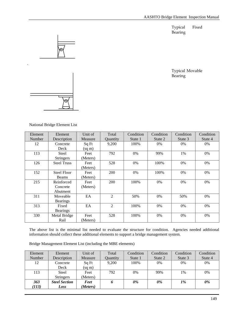
AASHTO Bridge Element Inspection Manual
149
`
Typical Fixed Bearing
Typical Movable Bearing
National Bridge Element List Element Number
Element Description
Unit of Measure
Total Quantity
Condition State 1
Condition State 2
Condition State 3
Condition State 4
12 Concrete Deck
Sq Ft (sq m)
9,200 100% 0% 0% 0%
113 Steel Stringers
Feet (Meters)
792 0% 99% 1% 0%
126 Steel Truss Feet (Meters)
528 0% 100% 0% 0%
152 Steel Floor Beams
Feet (Meters)
200 0% 100% 0% 0%
215 Reinforced Concrete Abutment
Feet (Meters)
200 100% 0% 0% 0%
311 Moveable Bearings
EA 2 50% 0% 50% 0%
313 Fixed Bearings
EA 2 100% 0% 0% 0%
330 Metal Bridge Rail
Feet (Meters)
528 100% 0% 0% 0%
The above list is the minimal list needed to evaluate the structure for condition. Agencies needed additional information should collect these additional elements to support a bridge management system. Bridge Management Element List (including the MBE elements) Element Number
Element Description
Unit of Measure
Total Quantity
Condition State 1
Condition State 2
Condition State 3
Condition State 4
12 Concrete Deck
Sq Ft (sq m)
9,200 100% 0% 0% 0%
113 Steel Stringers
Feet (Meters)
792 0% 99% 1% 0%
363 (113)
Steel Section Loss
Feet (Meters)
6 0% 0% 1% 0%
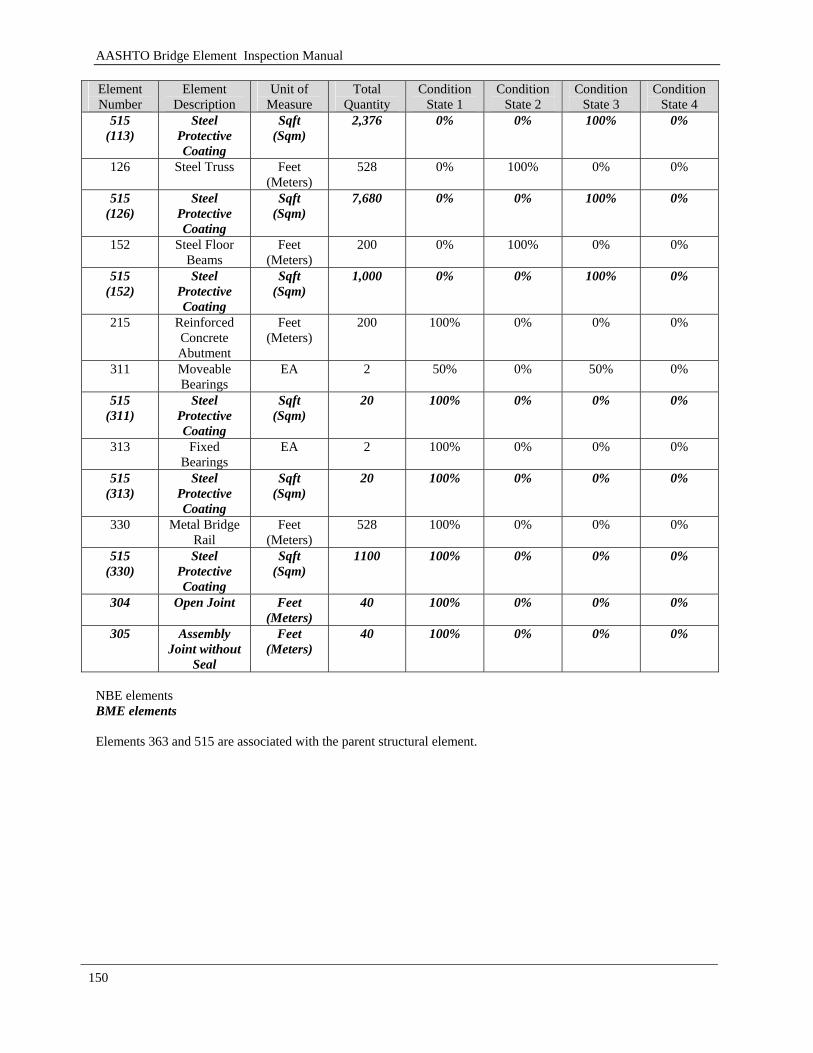
AASHTO Bridge Element Inspection Manual
150
Element Number
Element Description
Unit of Measure
Total Quantity
Condition State 1
Condition State 2
Condition State 3
Condition State 4
515 (113)
Steel Protective Coating
Sqft (Sqm)
2,376 0% 0% 100% 0%
126 Steel Truss Feet (Meters)
528 0% 100% 0% 0%
515 (126)
Steel Protective Coating
Sqft (Sqm)
7,680 0% 0% 100% 0%
152 Steel Floor Beams
Feet (Meters)
200 0% 100% 0% 0%
515 (152)
Steel Protective Coating
Sqft (Sqm)
1,000 0% 0% 100% 0%
215 Reinforced Concrete Abutment
Feet (Meters)
200 100% 0% 0% 0%
311 Moveable Bearings
EA 2 50% 0% 50% 0%
515 (311)
Steel Protective Coating
Sqft (Sqm)
20 100% 0% 0% 0%
313 Fixed Bearings
EA 2 100% 0% 0% 0%
515 (313)
Steel Protective Coating
Sqft (Sqm)
20 100% 0% 0% 0%
330 Metal Bridge Rail
Feet (Meters)
528 100% 0% 0% 0%
515 (330)
Steel Protective Coating
Sqft (Sqm)
1100 100% 0% 0% 0%
304 Open Joint Feet (Meters)
40 100% 0% 0% 0%
305 Assembly Joint without
Seal
Feet (Meters)
40 100% 0% 0% 0%
NBE elements BME elements Elements 363 and 515 are associated with the parent structural element.

AASHTO Bridge Element Inspection Manual
151
[BLANK PAGE]
AASHTO Bridge Element Inspection Manual
152
Appendix C Element Grouping
This section graphically displays the NBE, BME and obsolete elements. The charts show the elements by type, deck, superstructure, substructure and smart flags.
AASHTO Bridge Element Inspection Manual
153
[BLANK PAGE]

AASHTO Bridge Element Inspection Manual
154
C.1 National Bridge Elements (NBE)
National Bridge Elements (NBE)
Deck Superstructure Substructure
Reinforced Conc Deck
Slab(12/38)
Steel PS Conc R Conc Timber
PS/ Reinforced
concrete top flange (15)
Steel Deck Open Grid
(28)
Steel Deck Concrete Filled Grid
(29)
Steel Deck Corrugated / Orthotropic /
Etc (30)
Timber Deck/Slab
(31/54)
Masonry Steel PS Conc R Conc Timber Masonry
Closed Web / Box Girder
(102)
Girder Beam(107)
Stringer (113)
Truss (120)
Arch (141)
Floor Beam(152)
Cable (147)
Secondary Steel Cables
(148)
Gusset Plate (162)
Pin and/or Pin & hanger
Assembly (161)
Closed Web / Box Girder
(104)
Girder Beam(109)
Stringer (115)
Arch (143)
Floor Beam(154)
Closed Web / Box Girder
(105)
Girder Beam(110)
Stringer (116)
Arch (144)
Floor Beam(155)
Girder Beam(111)
Stringer (117)
Arch (146)
Floor Beam(156)
Truss (135)
Arch (145)
Column/ Pile
Extension (202)
Column Tower
(Trestle) (207)
Pier Wall(210)
Abutment(219)
Submerged Pile(225)
Column/ Pile
Extension (204)
Column/ Pile
Extension (205)
Column/ Pile
Extension (206)
Column Tower( Trestle)
(208)
Pier Wall(212)
Pier Wall(213)
Pier Wall(211)
Abutment(215)
Abutment(216)
Abutment(217)
Abutment(218)
Submerged Pile
(227)
Submerged Pile
(226)
Submerged Pile
(228)
Pile/Cap Footing (220)
Pier Cap(231)
Pier Cap(234)
Pier Cap(233)
Pier Cap(235)
Culvert(240)
Culvert(241)
Culvert(242)
Culvert(244)
Culvert(243)
Other
April 21, 2010 version
Bearings
ElastomericBearings
(310)
Moveable (roller,
sliding, etc)(311)
Enclosed/Concealed
Bearing(312)
Fixed Bearing
(313)
Pot Bearing
(314)
Disk Bearing
(315)
Bridge Rail
Metal Bridge Railing(330)
Reinforced Concrete
Bridge Railing(331)
Timber Bridge Railing(332)
Other Bridge Railing (333)
Masonry Bridge Railing(334)
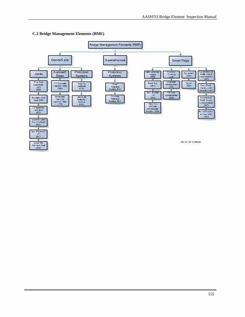
AASHTO Bridge Element Inspection Manual
155
C.2 Bridge Management Elements (BME)
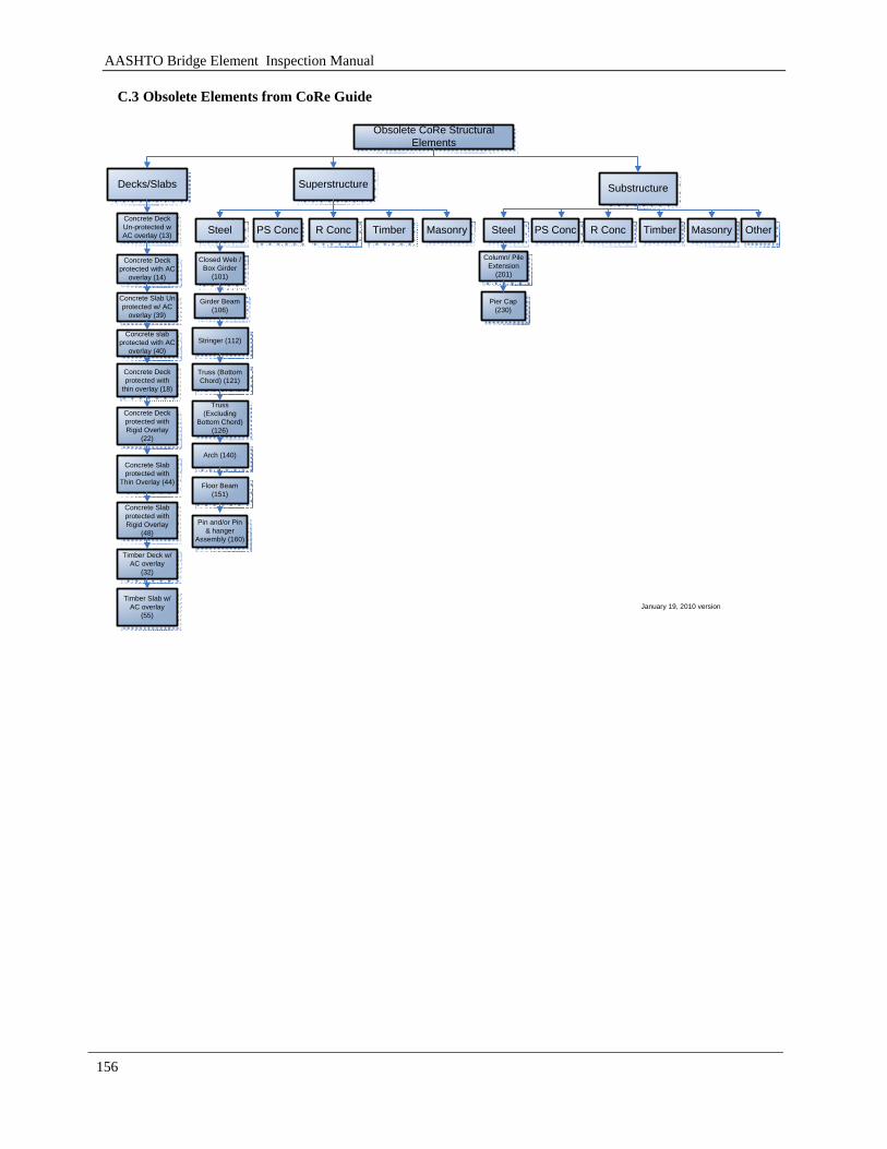
AASHTO Bridge Element Inspection Manual
156
C.3 Obsolete Elements from CoRe Guide
Obsolete CoRe Structural Elements
Decks/Slabs Superstructure Substructure
Concrete Deck Un-protected w AC overlay (13) Steel PS Conc R Conc Timber
Concrete Deck protected with AC
overlay (14)
Concrete Slab Un protected w/ AC
overlay (39)
Concrete slab protected with AC
overlay (40)
Concrete Deck protected with
thin overlay (18)
Concrete Deck protected with Rigid Overlay
(22)
Masonry Steel PS Conc R Conc Timber Masonry
Closed Web / Box Girder
(101)
Girder Beam(106)
Stringer (112)
Truss (Bottom Chord) (121)
Arch (140)
Floor Beam(151)
Pin and/or Pin & hanger
Assembly (160)
Column/ Pile Extension
(201)
Pier Cap(230)
Other
January 19, 2010 version
Truss (Excluding
Bottom Chord) (126)
Concrete Slab protected with
Thin Overlay (44)
Concrete Slab protected with Rigid Overlay
(48)
Timber Deck w/ AC overlay
(32)
Timber Slab w/ AC overlay
(55)
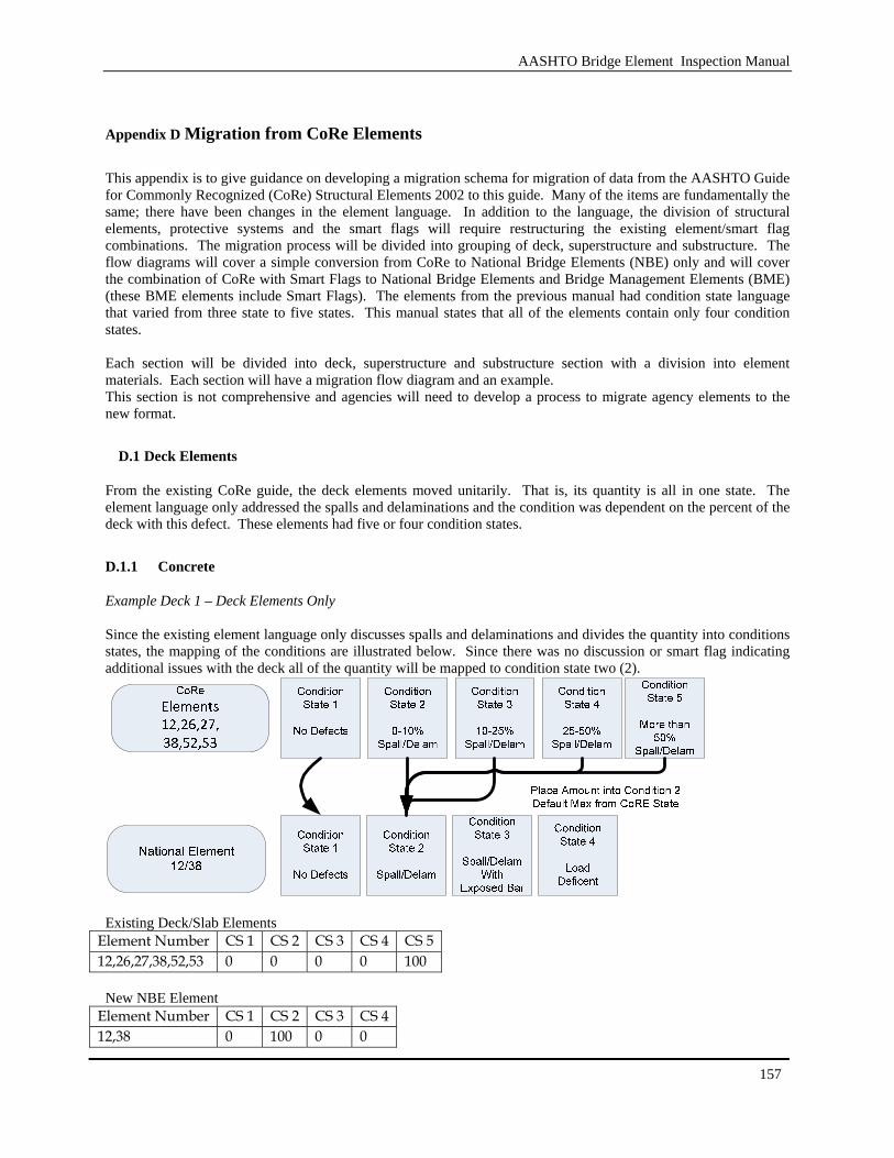
AASHTO Bridge Element Inspection Manual
157
Appendix D Migration from CoRe Elements
This appendix is to give guidance on developing a migration schema for migration of data from the AASHTO Guide for Commonly Recognized (CoRe) Structural Elements 2002 to this guide. Many of the items are fundamentally the same; there have been changes in the element language. In addition to the language, the division of structural elements, protective systems and the smart flags will require restructuring the existing element/smart flag combinations. The migration process will be divided into grouping of deck, superstructure and substructure. The flow diagrams will cover a simple conversion from CoRe to National Bridge Elements (NBE) only and will cover the combination of CoRe with Smart Flags to National Bridge Elements and Bridge Management Elements (BME) (these BME elements include Smart Flags). The elements from the previous manual had condition state language that varied from three state to five states. This manual states that all of the elements contain only four condition states. Each section will be divided into deck, superstructure and substructure section with a division into element materials. Each section will have a migration flow diagram and an example. This section is not comprehensive and agencies will need to develop a process to migrate agency elements to the new format.
D.1 Deck Elements
From the existing CoRe guide, the deck elements moved unitarily. That is, its quantity is all in one state. The element language only addressed the spalls and delaminations and the condition was dependent on the percent of the deck with this defect. These elements had five or four condition states.
D.1.1 Concrete
Example Deck 1 – Deck Elements Only Since the existing element language only discusses spalls and delaminations and divides the quantity into conditions states, the mapping of the conditions are illustrated below. Since there was no discussion or smart flag indicating additional issues with the deck all of the quantity will be mapped to condition state two (2).
Existing Deck/Slab Elements
Element Number CS 1 CS 2 CS 3 CS 4 CS 5 12,26,27,38,52,53 0 0 0 0 100
New NBE Element
Element Number CS 1 CS 2 CS 3 CS 4 12,38 0 100 0 0

AASHTO Bridge Element Inspection Manual
158
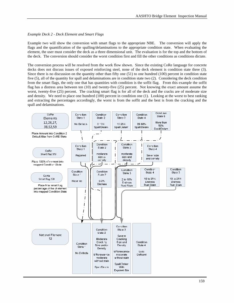
AASHTO Bridge Element Inspection Manual
159
Example Deck 2 - Deck Element and Smart Flags Example two will show the conversion with smart flags to the appropriate NBE. The conversion will apply the flags and the quantification of the spalling/delaminations to the appropriate condition state. When evaluating the element, the user must consider the deck as a three dimensional unit. The evaluation is for the top and the bottom of the deck. The conversion should consider the worst condition first and fill the other conditions as conditions dictate. The conversion process will be resolved from the work flow shown. Since the existing CoRe language for concrete decks does not discuss issues of exposed reinforcing steel, none of the deck element is condition state three (3). Since there is no discussion on the quantity other than fifty one (51) to one hundred (100) percent in condition state five (5), all of the quantity for spall and delaminations are in condition state two (2). Considering the deck condition from the smart flags, the only one that has quantities with condition is the soffit flag. From this example the soffit flag has a distress area between ten (10) and twenty-five (25) percent. Not knowing the exact amount assume the worst, twenty-five (25) percent. The cracking smart flag is for all of the deck and the cracks are of moderate size and density. We need to place one hundred (100) percent in condition one (1). Looking at the worst to best ranking and extracting the percentages accordingly, the worst is from the soffit and the best is from the cracking and the spall and delaminations.
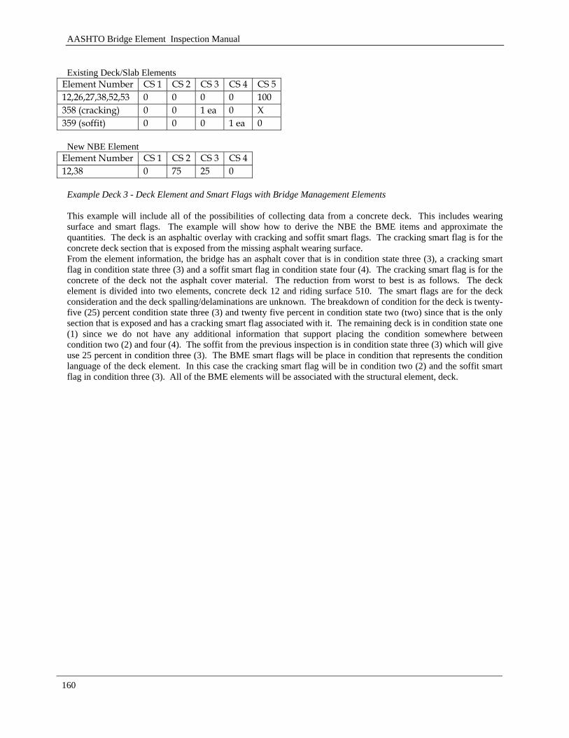
AASHTO Bridge Element Inspection Manual
160
Existing Deck/Slab Elements
Element Number CS 1 CS 2 CS 3 CS 4 CS 5 12,26,27,38,52,53 0 0 0 0 100 358 (cracking) 0 0 1 ea 0 X 359 (soffit) 0 0 0 1 ea 0
New NBE Element
Element Number CS 1 CS 2 CS 3 CS 4 12,38 0 75 25 0
Example Deck 3 - Deck Element and Smart Flags with Bridge Management Elements This example will include all of the possibilities of collecting data from a concrete deck. This includes wearing surface and smart flags. The example will show how to derive the NBE the BME items and approximate the quantities. The deck is an asphaltic overlay with cracking and soffit smart flags. The cracking smart flag is for the concrete deck section that is exposed from the missing asphalt wearing surface. From the element information, the bridge has an asphalt cover that is in condition state three (3), a cracking smart flag in condition state three (3) and a soffit smart flag in condition state four (4). The cracking smart flag is for the concrete of the deck not the asphalt cover material. The reduction from worst to best is as follows. The deck element is divided into two elements, concrete deck 12 and riding surface 510. The smart flags are for the deck consideration and the deck spalling/delaminations are unknown. The breakdown of condition for the deck is twenty-five (25) percent condition state three (3) and twenty five percent in condition state two (two) since that is the only section that is exposed and has a cracking smart flag associated with it. The remaining deck is in condition state one (1) since we do not have any additional information that support placing the condition somewhere between condition two (2) and four (4). The soffit from the previous inspection is in condition state three (3) which will give use 25 percent in condition three (3). The BME smart flags will be place in condition that represents the condition language of the deck element. In this case the cracking smart flag will be in condition two (2) and the soffit smart flag in condition three (3). All of the BME elements will be associated with the structural element, deck.
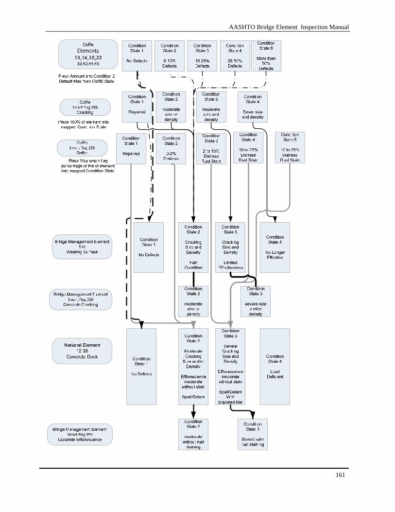
AASHTO Bridge Element Inspection Manual
161
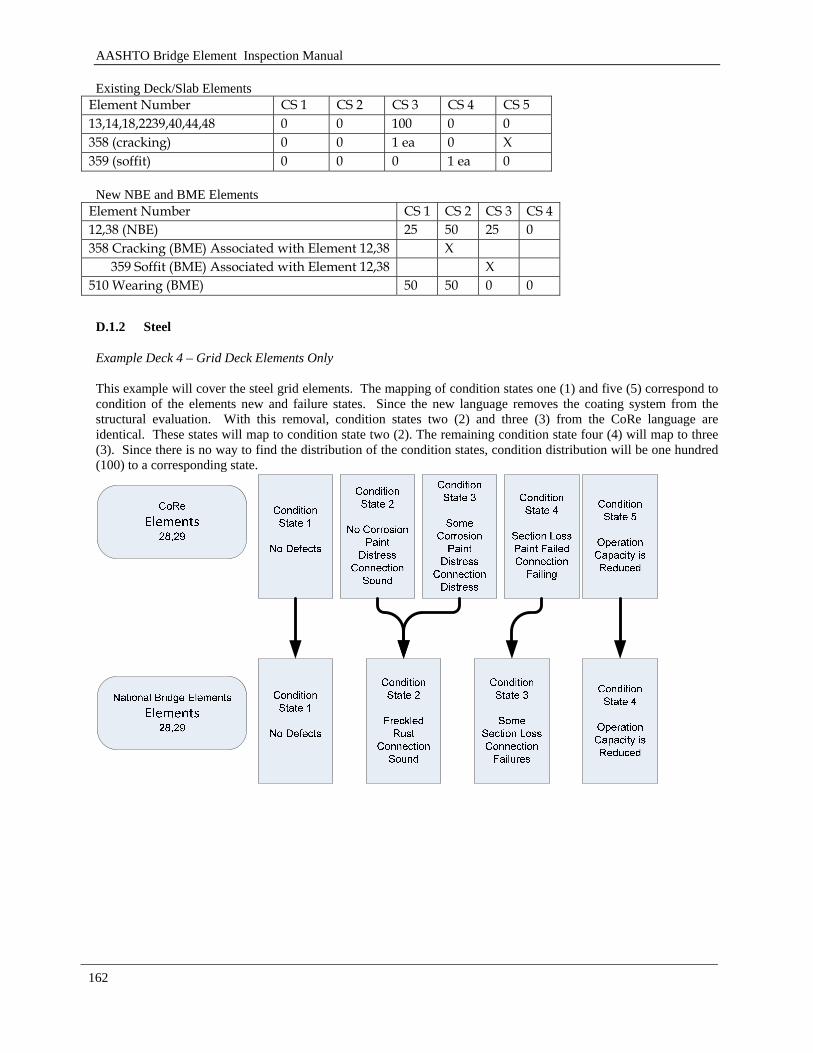
AASHTO Bridge Element Inspection Manual
162
Existing Deck/Slab Elements Element Number CS 1 CS 2 CS 3 CS 4 CS 5 13,14,18,2239,40,44,48 0 0 100 0 0 358 (cracking) 0 0 1 ea 0 X 359 (soffit) 0 0 0 1 ea 0
New NBE and BME Elements
Element Number CS 1 CS 2 CS 3 CS 4 12,38 (NBE) 25 50 25 0 358 Cracking (BME) Associated with Element 12,38 X
359 Soffit (BME) Associated with Element 12,38 X 510 Wearing (BME) 50 50 0 0
D.1.2 Steel
Example Deck 4 – Grid Deck Elements Only This example will cover the steel grid elements. The mapping of condition states one (1) and five (5) correspond to condition of the elements new and failure states. Since the new language removes the coating system from the structural evaluation. With this removal, condition states two (2) and three (3) from the CoRe language are identical. These states will map to condition state two (2). The remaining condition state four (4) will map to three (3). Since there is no way to find the distribution of the condition states, condition distribution will be one hundred (100) to a corresponding state.
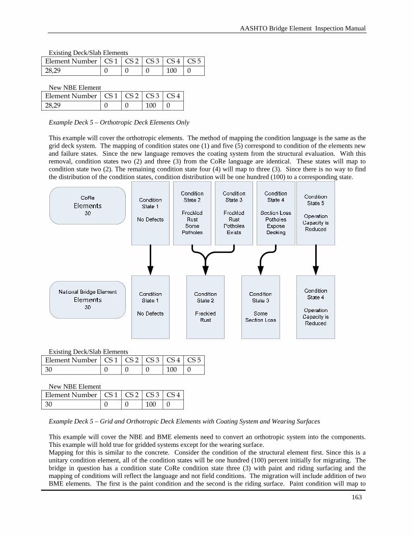
AASHTO Bridge Element Inspection Manual
163
Existing Deck/Slab Elements
Element Number CS 1 CS 2 CS 3 CS 4 CS 5 28,29 0 0 0 100 0
New NBE Element
Element Number CS 1 CS 2 CS 3 CS 4 28,29 0 0 100 0
Example Deck 5 – Orthotropic Deck Elements Only This example will cover the orthotropic elements. The method of mapping the condition language is the same as the grid deck system. The mapping of condition states one (1) and five (5) correspond to condition of the elements new and failure states. Since the new language removes the coating system from the structural evaluation. With this removal, condition states two (2) and three (3) from the CoRe language are identical. These states will map to condition state two (2). The remaining condition state four (4) will map to three (3). Since there is no way to find the distribution of the condition states, condition distribution will be one hundred (100) to a corresponding state.
Existing Deck/Slab Elements
Element Number CS 1 CS 2 CS 3 CS 4 CS 5 30 0 0 0 100 0
New NBE Element
Element Number CS 1 CS 2 CS 3 CS 4 30 0 0 100 0
Example Deck 5 – Grid and Orthotropic Deck Elements with Coating System and Wearing Surfaces This example will cover the NBE and BME elements need to convert an orthotropic system into the components. This example will hold true for gridded systems except for the wearing surface. Mapping for this is similar to the concrete. Consider the condition of the structural element first. Since this is a unitary condition element, all of the condition states will be one hundred (100) percent initially for migrating. The bridge in question has a condition state CoRe condition state three (3) with paint and riding surfacing and the mapping of conditions will reflect the language and not field conditions. The migration will include addition of two BME elements. The first is the paint condition and the second is the riding surface. Paint condition will map to
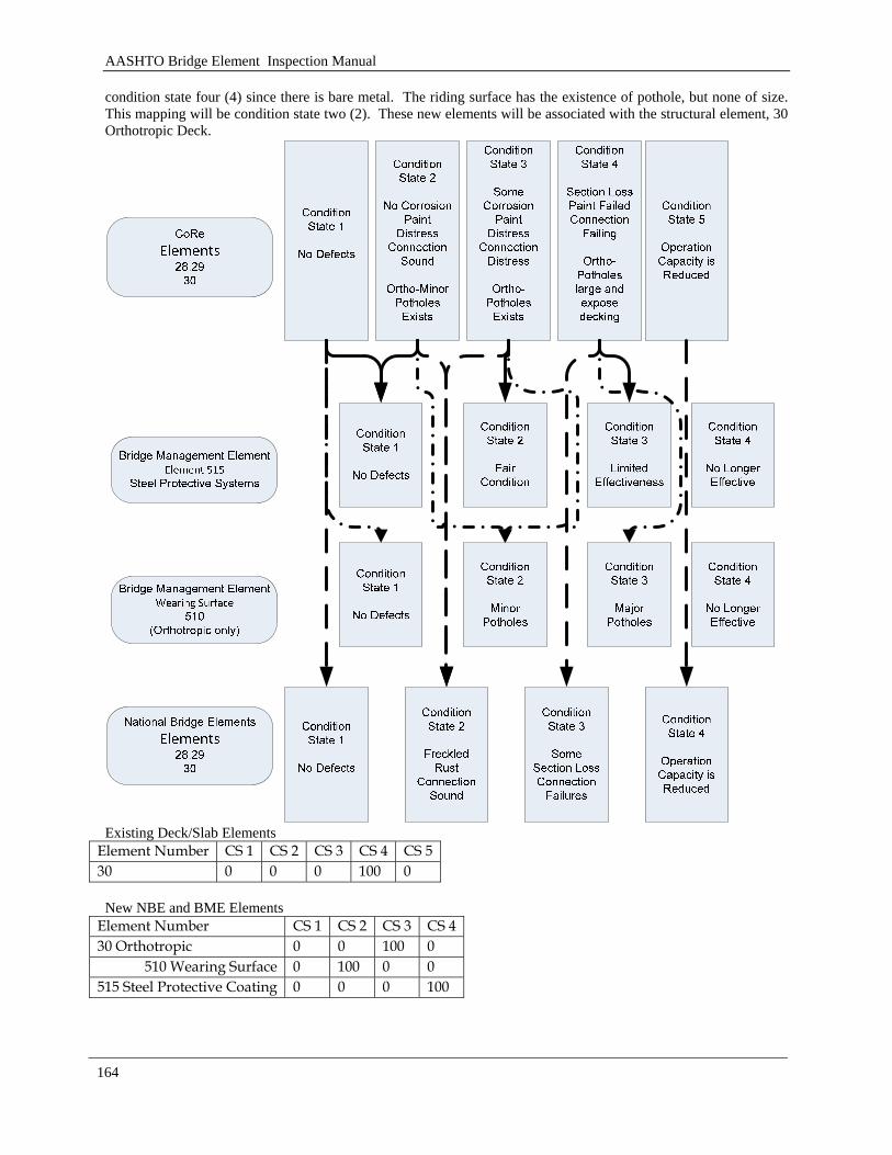
AASHTO Bridge Element Inspection Manual
164
condition state four (4) since there is bare metal. The riding surface has the existence of pothole, but none of size. This mapping will be condition state two (2). These new elements will be associated with the structural element, 30 Orthotropic Deck.
Existing Deck/Slab Elements
Element Number CS 1 CS 2 CS 3 CS 4 CS 5 30 0 0 0 100 0
New NBE and BME Elements
Element Number CS 1 CS 2 CS 3 CS 4 30 Orthotropic 0 0 100 0
510 Wearing Surface 0 100 0 0 515 Steel Protective Coating 0 0 0 100
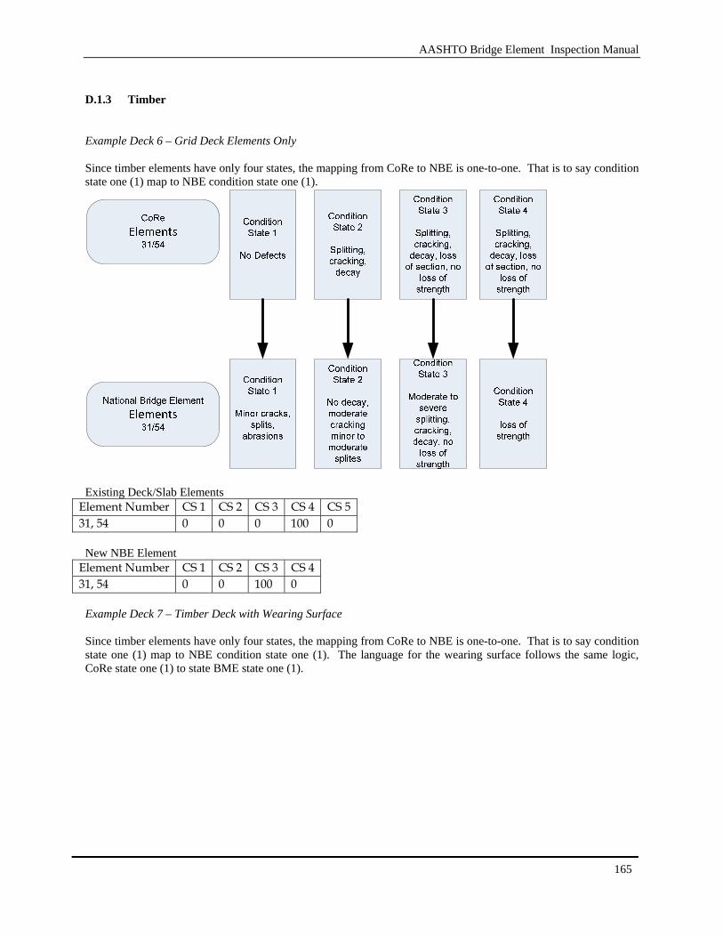
AASHTO Bridge Element Inspection Manual
165
D.1.3 Timber
Example Deck 6 – Grid Deck Elements Only Since timber elements have only four states, the mapping from CoRe to NBE is one-to-one. That is to say condition state one (1) map to NBE condition state one (1).
Existing Deck/Slab Elements
Element Number CS 1 CS 2 CS 3 CS 4 CS 5 31, 54 0 0 0 100 0
New NBE Element
Element Number CS 1 CS 2 CS 3 CS 4 31, 54 0 0 100 0
Example Deck 7 – Timber Deck with Wearing Surface Since timber elements have only four states, the mapping from CoRe to NBE is one-to-one. That is to say condition state one (1) map to NBE condition state one (1). The language for the wearing surface follows the same logic, CoRe state one (1) to state BME state one (1).

AASHTO Bridge Element Inspection Manual
166
Existing Deck/Slab Elements
Element Number CS 1 CS 2 CS 3 CS 4 CS 5 32, 55 0 0 0 100 0 New NBE Element
Element Number CS 1 CS 2 CS 3 CS 4 31, 54 0 0 100 0 510 Wearing Surface 0 0 100 0
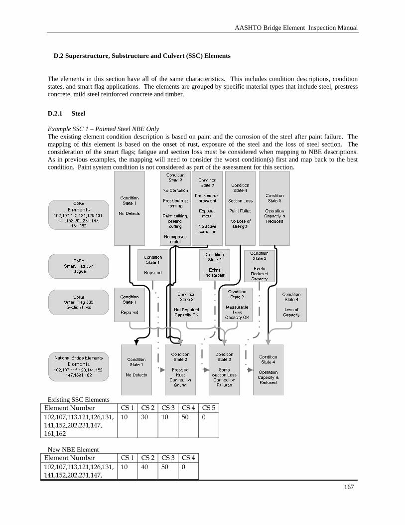
AASHTO Bridge Element Inspection Manual
167
D.2 Superstructure, Substructure and Culvert (SSC) Elements
The elements in this section have all of the same characteristics. This includes condition descriptions, condition states, and smart flag applications. The elements are grouped by specific material types that include steel, prestress concrete, mild steel reinforced concrete and timber.
D.2.1 Steel
Example SSC 1 – Painted Steel NBE Only The existing element condition description is based on paint and the corrosion of the steel after paint failure. The mapping of this element is based on the onset of rust, exposure of the steel and the loss of steel section. The consideration of the smart flags; fatigue and section loss must be considered when mapping to NBE descriptions. As in previous examples, the mapping will need to consider the worst condition(s) first and map back to the best condition. Paint system condition is not considered as part of the assessment for this section.
Existing SSC Elements
Element Number CS 1 CS 2 CS 3 CS 4 CS 5 102,107,113,121,126,131, 141,152,202,231,147, 161,162
10 30 10 50 0
New NBE Element
Element Number CS 1 CS 2 CS 3 CS 4 102,107,113,121,126,131, 141,152,202,231,147,
10 40 50 0

AASHTO Bridge Element Inspection Manual
168
161,162 Example SSC 2 – Painted Steel NBE and BME The existing element condition description is based on paint and the corrosion of the steel after paint failure. The mapping of this element is based on the onset of rust, exposure of the steel and the loss of steel section. The consideration of the smart flags; fatigue and section loss must be considered when mapping to NBE descriptions. As in previous examples, the mapping will need to consider the worst condition(s) first and map back to the best condition. The introduction of the smart flags will adjust the quantities in various states because the CoRe flags are bridge level and will need to be applied at a one hundred (100) percent in a given condition state. Paint system considerations need to be separated from the structural consideration.
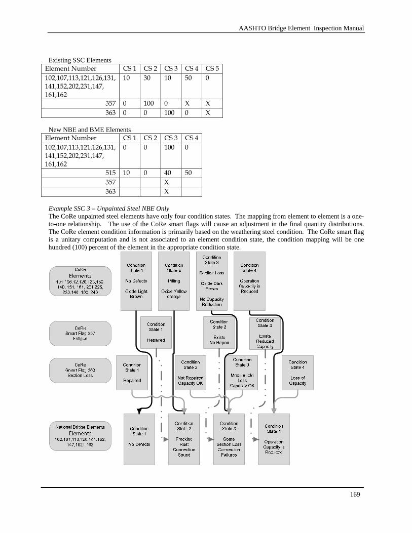
AASHTO Bridge Element Inspection Manual
169
Existing SSC Elements
Element Number CS 1 CS 2 CS 3 CS 4 CS 5 102,107,113,121,126,131, 141,152,202,231,147, 161,162
10 30 10 50 0
357 0 100 0 X X 363 0 0 100 0 X
New NBE and BME Elements
Element Number CS 1 CS 2 CS 3 CS 4 102,107,113,121,126,131, 141,152,202,231,147, 161,162
0 0 100 0
515 10 0 40 50 357 X 363 X
Example SSC 3 – Unpainted Steel NBE Only The CoRe unpainted steel elements have only four condition states. The mapping from element to element is a one-to-one relationship. The use of the CoRe smart flags will cause an adjustment in the final quantity distributions. The CoRe element condition information is primarily based on the weathering steel condition. The CoRe smart flag is a unitary computation and is not associated to an element condition state, the condition mapping will be one hundred (100) percent of the element in the appropriate condition state.
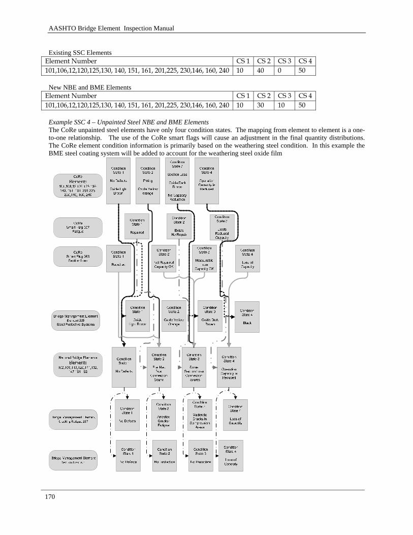
AASHTO Bridge Element Inspection Manual
170
Existing SSC Elements
Element Number CS 1 CS 2 CS 3 CS 4 101,106,12,120,125,130, 140, 151, 161, 201,225, 230,146, 160, 240 10 40 0 50
New NBE and BME Elements
Element Number CS 1 CS 2 CS 3 CS 4 101,106,12,120,125,130, 140, 151, 161, 201,225, 230,146, 160, 240 10 30 10 50
Example SSC 4 – Unpainted Steel NBE and BME Elements The CoRe unpainted steel elements have only four condition states. The mapping from element to element is a one-to-one relationship. The use of the CoRe smart flags will cause an adjustment in the final quantity distributions. The CoRe element condition information is primarily based on the weathering steel condition. In this example the BME steel coating system will be added to account for the weathering steel oxide film
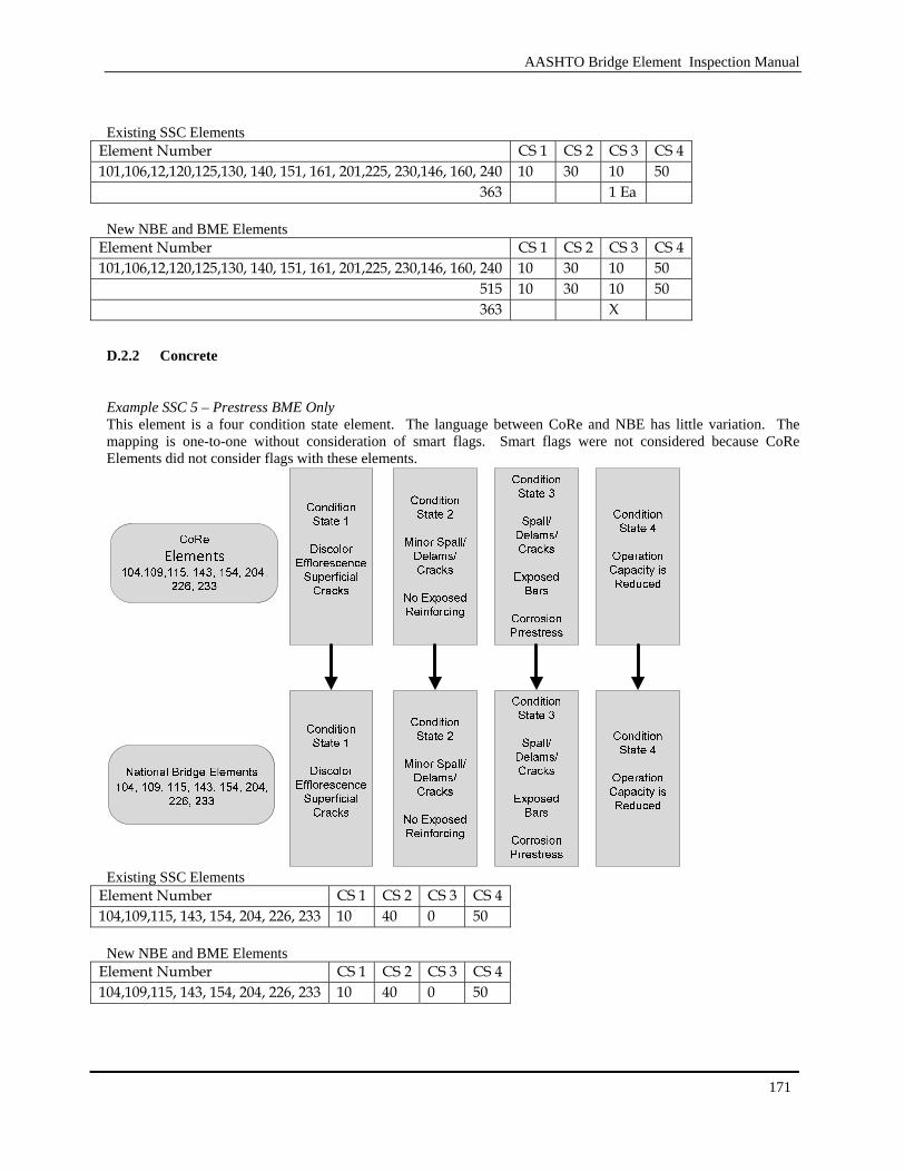
AASHTO Bridge Element Inspection Manual
171
Existing SSC Elements
Element Number CS 1 CS 2 CS 3 CS 4 101,106,12,120,125,130, 140, 151, 161, 201,225, 230,146, 160, 240 10 30 10 50
363 1 Ea New NBE and BME Elements
Element Number CS 1 CS 2 CS 3 CS 4 101,106,12,120,125,130, 140, 151, 161, 201,225, 230,146, 160, 240 10 30 10 50
515 10 30 10 50 363 X
D.2.2 Concrete
Example SSC 5 – Prestress BME Only This element is a four condition state element. The language between CoRe and NBE has little variation. The mapping is one-to-one without consideration of smart flags. Smart flags were not considered because CoRe Elements did not consider flags with these elements.
Existing SSC Elements
Element Number CS 1 CS 2 CS 3 CS 4 104,109,115, 143, 154, 204, 226, 233 10 40 0 50
New NBE and BME Elements
Element Number CS 1 CS 2 CS 3 CS 4 104,109,115, 143, 154, 204, 226, 233 10 40 0 50
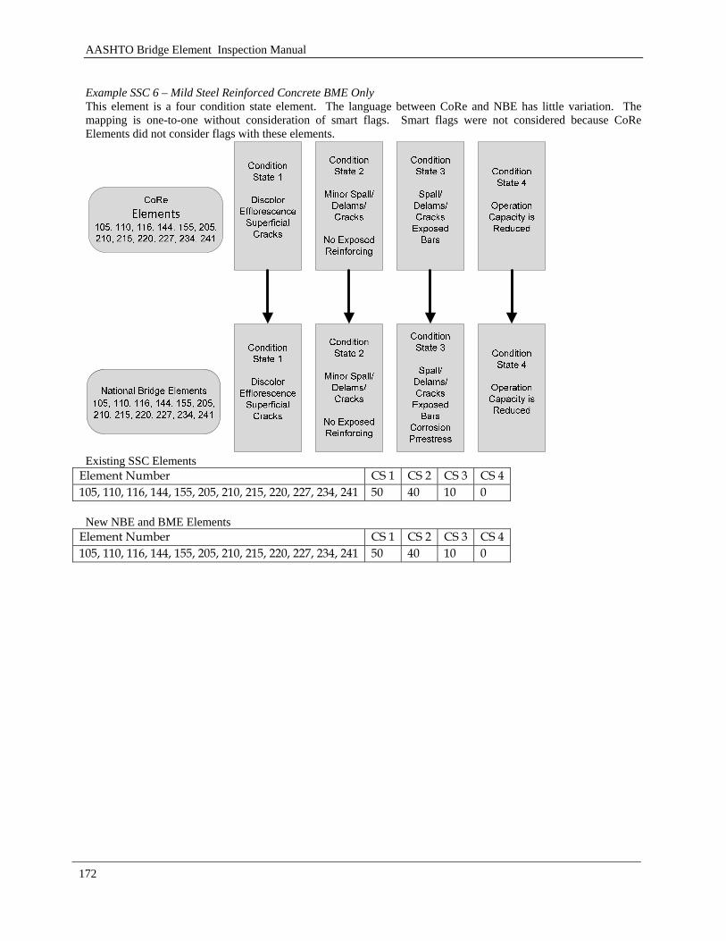
AASHTO Bridge Element Inspection Manual
172
Example SSC 6 – Mild Steel Reinforced Concrete BME Only This element is a four condition state element. The language between CoRe and NBE has little variation. The mapping is one-to-one without consideration of smart flags. Smart flags were not considered because CoRe Elements did not consider flags with these elements.
Existing SSC Elements
Element Number CS 1 CS 2 CS 3 CS 4 105, 110, 116, 144, 155, 205, 210, 215, 220, 227, 234, 241 50 40 10 0
New NBE and BME Elements
Element Number CS 1 CS 2 CS 3 CS 4 105, 110, 116, 144, 155, 205, 210, 215, 220, 227, 234, 241 50 40 10 0
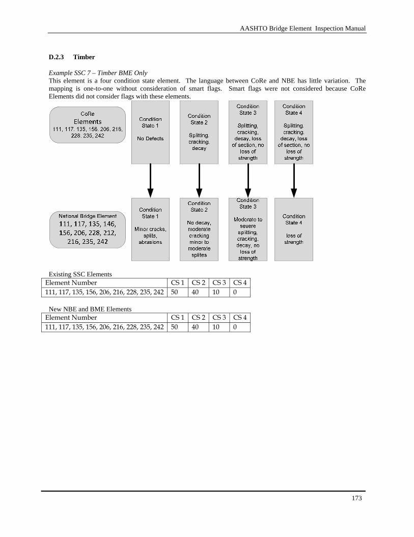
AASHTO Bridge Element Inspection Manual
173
D.2.3 Timber
Example SSC 7 – Timber BME Only This element is a four condition state element. The language between CoRe and NBE has little variation. The mapping is one-to-one without consideration of smart flags. Smart flags were not considered because CoRe Elements did not consider flags with these elements.
Existing SSC Elements
Element Number CS 1 CS 2 CS 3 CS 4 111, 117, 135, 156, 206, 216, 228, 235, 242 50 40 10 0
New NBE and BME Elements
Element Number CS 1 CS 2 CS 3 CS 4 111, 117, 135, 156, 206, 216, 228, 235, 242 50 40 10 0
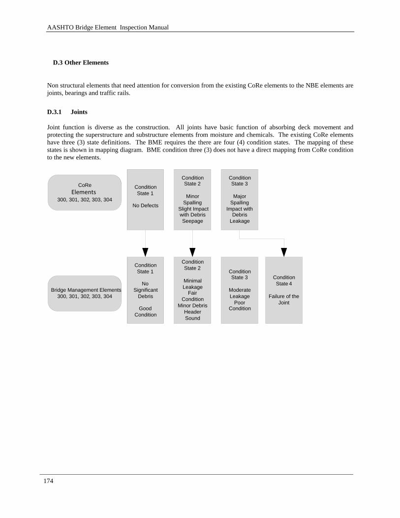
AASHTO Bridge Element Inspection Manual
174
D.3 Other Elements
Non structural elements that need attention for conversion from the existing CoRe elements to the NBE elements are joints, bearings and traffic rails.
D.3.1 Joints
Joint function is diverse as the construction. All joints have basic function of absorbing deck movement and protecting the superstructure and substructure elements from moisture and chemicals. The existing CoRe elements have three (3) state definitions. The BME requires the there are four (4) condition states. The mapping of these states is shown in mapping diagram. BME condition three (3) does not have a direct mapping from CoRe condition to the new elements.
Condition State 1
No Defects
ConditionState 2
Minor Spalling
Slight Impact with DebrisSeepage
ConditionState 3
Major Spalling
Impact with Debris
Leakage
CoRe Elements
300 , 301, 302 , 303 , 304
Bridge Management Elements 300 , 301, 302 , 303 , 304
Condition State 1
No Significant
Debris
Good Condition
ConditionState 2
Minimal Leakage
Fair Condition
Minor DebrisHeader Sound
ConditionState 3
Moderate Leakage
Poor Condition
Condition State 4
Failure of the Joint
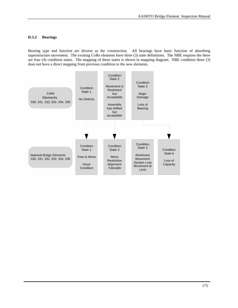
AASHTO Bridge Element Inspection Manual
175
D.3.2 Bearings
Bearing type and function are diverse as the construction. All bearings have basic function of absorbing superstructure movement. The existing CoRe elements have three (3) state definitions. The NBE requires the there are four (4) condition states. The mapping of these states is shown in mapping diagram. NBE condition three (3) does not have a direct mapping from previous condition to the new elements.
Condition State 1
No Defects
ConditionState 2
Movement is Restricted
but Acceptable
Assembly has shifted
but acceptable
ConditionState 3
Major Damage
Loss of Bearing
CoRe Elements
330, 331 , 332 , 333 , 334, 335
National Bridge Elements 330, 331 , 332 , 333 , 334, 335
Condition State 1
Free to Move
Good Condition
ConditionState 2
Minor RestrictionAlignment Tolerable
ConditionState 3
Restricted Movement
Section LossMovement at
Limit
Condition State 4
Loss of Capacity
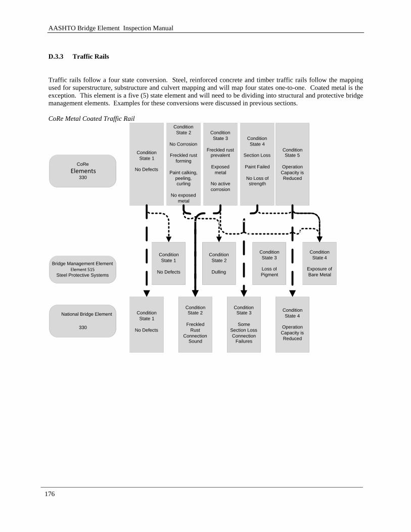
AASHTO Bridge Element Inspection Manual
176
D.3.3 Traffic Rails
Traffic rails follow a four state conversion. Steel, reinforced concrete and timber traffic rails follow the mapping used for superstructure, substructure and culvert mapping and will map four states one-to-one. Coated metal is the exception. This element is a five (5) state element and will need to be dividing into structural and protective bridge management elements. Examples for these conversions were discussed in previous sections. CoRe Metal Coated Traffic Rail
ConditionState 1
No Defects
ConditionState 2
No Corrosion
Freckled rust forming
Paint calking, peeling, curling
No exposed metal
ConditionState 3
Freckled rust prevalent
Exposed metal
No active corrosion
ConditionState 4
Section Loss
Paint Failed
No Loss of strength
Condition State 5
Operation Capacity is Reduced
CoRe Elements
330
ConditionState 1
No Defects
ConditionState 2
Freckled Rust
Connection Sound
ConditionState 3
Some Section LossConnection
Failures
Condition State 4
Operation Capacity is Reduced
National Bridge Element
330
ConditionState 2
Dulling
ConditionState 3
Loss ofPigment
Condition State 4
Exposure of Bare Metal
Bridge Management ElementElement 515
Steel Protective Systems
ConditionState 1
No Defects
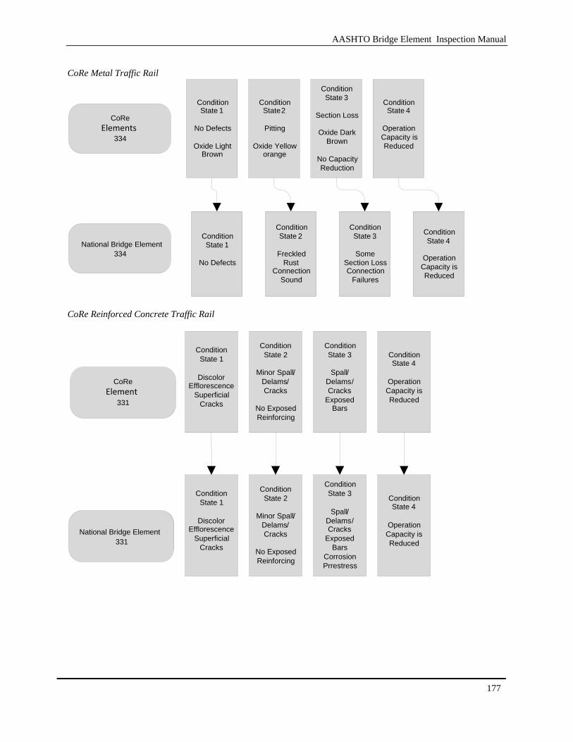
AASHTO Bridge Element Inspection Manual
177
CoRe Metal Traffic Rail
CoRe Reinforced Concrete Traffic Rail
Condition State 1
DiscolorEfflorescence
Superficial Cracks
ConditionState 2
Minor Spall/Delams/Cracks
No Exposed Reinforcing
ConditionState 3
Spall/Delams/Cracks
Exposed Bars
Condition State 4
Operation Capacity is Reduced
CoRe Element
331
Condition State 1
DiscolorEfflorescence
Superficial Cracks
ConditionState 2
Minor Spall/Delams/Cracks
No Exposed Reinforcing
ConditionState 3
Spall/Delams/Cracks
Exposed Bars
Corrosion Prrestress
Condition State 4
Operation Capacity is Reduced
National Bridge Element 331
CoRe Elements
334
ConditionState 1
No Defects
ConditionState 2
Freckled Rust
Connection Sound
ConditionState 3
Some Section LossConnection
Failures
Condition State 4
Operation Capacity is Reduced
National Bridge Element 334
Condition State 1
No Defects
Oxide Light Brown
ConditionState 2
Pitting
Oxide Yellow orange
ConditionState 3
Section Loss
Oxide Dark Brown
No Capacity Reduction
Condition State 4
Operation Capacity is Reduced
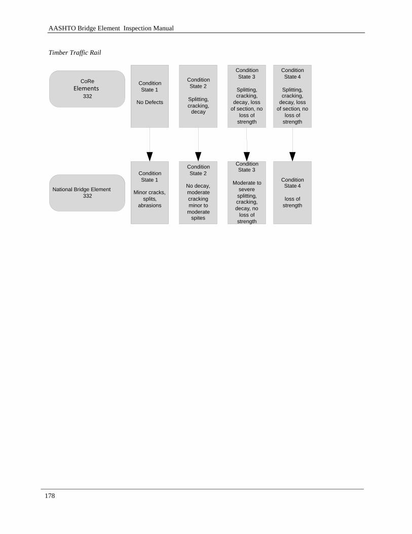
AASHTO Bridge Element Inspection Manual
178
Timber Traffic Rail
Condition State 1
No Defects
ConditionState 2
Splitting, cracking,
decay
ConditionState 3
Splitting, cracking,
decay, loss of section, no
loss of strength
Condition State 4
Splitting , cracking,
decay , loss of section, no
loss of strength
CoRe Elements
332
National Bridge Element 332
Condition State 1
Minor cracks, splits ,
abrasions
ConditionState 2
No decay, moderate cracking minor to
moderate spites
ConditionState 3
Moderate to severe
splitting, cracking, decay, no
loss of strength
Condition State 4
loss of strength