Embed Size (px)
Citation preview
© b
y D
oka
Gm
bH, A
-330
0 Am
stet
ten
999770002 09/2018en-GB
-
The Formwork Experts.
Bridge edge beam formwork TUser InformationInstructions for assembly and use (Method statement)© by Doka GmbH, A-3300 Amstetten
9770-200-01
2 999770002 - 09/2018
User Information Bridge edge beam formwork T
User Information Bridge edge beam formwork T
3999770002 - 09/2018
Contents
4 Introduction4 Elementary safety warnings7 Eurocodes at Doka8 Doka services
10 System overview
12 Structural design12 Basic system13 Structural design with Handrail post T 1.80m
14 Instructions for assembly and use (Method statement)
16 Anchoring on the structure16 Suspension point with Bridge edge beam
anchor19 Retrofitted suspension points
20 Assembly20 Manual erection22 Erecting the formwork
23 Additional areas of use23 Platforms on wide edge beams24 Possible ways of using the Handrail post T
1.80m28 Platforms on bridges over traffic routes30 Other possible areas of use
35 General remarks35 Fall-arrest systems on the structure36 Transporting, stacking and storing
40 Component overview
4 999770002 - 09/2018
Introduction User Information Bridge edge beam formwork T
IntroductionElementary safety warnings
User target groups
▪ This booklet is aimed at all persons who will be work-ing with the Doka product or system that it describes. It contains information on the standard design for setting up this system, and on correct, compliant uti-lisation of the system.
▪ All persons working with the product described herein must be familiar with the contents of this booklet and with all the safety instructions it contains.
▪ Persons who are incapable of reading and under-standing this booklet, or who can do so only with dif-ficulty, must be instructed and trained by the cus-tomer.
▪ The customer is to ensure that the information mate-rials provided by Doka (e.g. User Information book-lets, Instructions for Assembly and Use, Operating Instruction manuals, plans etc.) are up to date and available to all users, and that they have been made aware of them and have easy access to them at the usage location.
▪ In the relevant technical documentation and form-work utilisation plans, Doka shows the workplace safety precautions that are necessary in order to use the Doka products safely in the usage situations shown. In all cases, users are obliged to ensure compliance with national laws, standards and regulations throughout the entire project and to take appropriate additional or alternative workplace safety precau-tions where necessary.
Hazard assessment
▪ The customer is responsible for drawing up, docu-menting, implementing and continually updating a hazard assessment at every job-site. This booklet serves as the basis for the site-specific hazard assessment, and for the instructions given to users on how to prepare and utilise the system. It does not substitute for these, however.
Remarks on this booklet
▪ This booklet can also be used as a generic method statement or incorporated with a site-specific method statement.
▪ Many of the illustrations in this booklet show the situation during formwork assembly and are therefore not always complete from the safety point of view.Any safety accessories not shown in these illustra-tions must still be used by the customer, in accord-ance with the applicable rules and regulations.
▪ Further safety instructions, especially warnings, will be found in the individual sections of this booklet!
Planning
▪ Provide safe workplaces for those using the form-work (e.g. for when it is being erected/dismantled, modified or repositioned etc). It must be possible to get to and from these workplaces via safe access routes!
▪ If you are considering any deviation from the details and instructions given in this booklet, or any application which goes beyond those described in the booklet, then revised static cal-culations must be produced for checking, as well as supplementary assembly instructions.
Regulations; industrial safety
▪ All laws, Standards, industrial safety regulations and other safety rules applying to the utilisation of our products in the country and/or region in which you are operating must be observed at all times.
▪ If a person or object falls against, or into, the side-guard component and/or any of its accessories, the component affected may only continue in use after it has been inspected and passed by an expert.
User Information Bridge edge beam formwork T Introduction
5999770002 - 09/2018
Rules applying during all phases of the assignment
▪ The customer must ensure that this product is erected and dismantled, reset and generally used for its intended purpose in accordance with the applica-ble laws, standards and rules, under the direction and supervision of suitably skilled persons. These persons' mental and physical capacity must not in any way be impaired by alcohol, medicines or drugs.
▪ Doka products are technical working appliances which are intended for industrial / commercial use only, always in accordance with the respective Doka User Information booklets or other technical docu-mentation authored by Doka.
▪ The stability and load-bearing capacity of all compo-nents and units must be ensured during all phases of the construction work!
▪ Do not step on or apply strain to cantilevers, clo-sures, etc. until suitable measures to ensure their stability have been correctly implemented (e.g. by tie-backs).
▪ Strict attention to and compliance with the functional instructions, safety instructions and load specifica-tions are required. Non-compliance can cause acci-dents and severe injury (risk of fatality) and consid-erable damage to property.
▪ Sources of fire in the vicinity of the formwork are pro-hibited. Heating appliances are only allowed if prop-erly and expertly used, and set up a safe distance away from the formwork.
▪ The customer must consider all types of weather conditions on equipment and in connection with the use or storage of the equipment (e.g. slippery sur-faces, risk of slippage, effects of wind, etc.) and must take steps in good time to safeguard the equipment and the surrounding areas and to protect the work-ers.
▪ All connections must be checked at regular intervals to ensure that they are secure and in full working order. In particular threaded connections and wedged con-nections have to be checked and retightened as nec-essary in accordance with activity on the jobsite and especially after out-of-the-ordinary occurrences (e.g. after a storm).
▪ It is strictly forbidden to weld Doka products – in par-ticular anchoring/tying components, suspension components, connector components and castings etc. – or otherwise subject them to heating.Welding causes serious change in the microstruc-ture of the materials from which these components are made. This leads to a dramatic drop in the failure load, representing a very great risk to safety.It is permissible to cut tie rods to length with metal cutting discs (introduction of heat at the end of the rod only), but it is important to ensure that flying sparks do not heat and thus damage other tie rods.The only articles which are allowed to be welded are those for which the Doka literature expressly points out that welding is permitted.
Assembly
▪ The equipment/system must be inspected by the customer before use, to ensure that it is in suitable condition. Steps must be taken to rule out the use of any components that are damaged, deformed, or weakened due to wear, corrosion or rot.
▪ Combining our formwork systems with those of other manufacturers could be dangerous, risking damage to both health and property. If you intend to combine different systems, please contact Doka for advice first.
▪ The equipment/system must be assembled and erected in accordance with the applicable laws, Standards and rules by suitably skilled personnel of the customer's, having regard to any and all required safety inspections.
▪ It is not permitted to modify Doka products; any such modifications constitute a safety risk.
Closing the formwork
▪ Doka products and systems must be set up so that all loads acting upon them are safely transferred!
Pouring
▪ Do not exceed the permitted fresh-concrete pres-sures. Over-high pouring rates overload the form-work, cause greater deflection and risk breakage.
Stripping out the formwork
▪ Do not strip out the formwork until the concrete has reached sufficient strength and the person in charge has given the order for the formwork to be stripped out!
▪ When stripping out the formwork, never use the crane to break concrete cohesion. Use suitable tools such as timber wedges, special pry-bars or system features such as Framax stripping corners.
▪ When stripping out the formwork, do not endanger the stability of any part of the structure, or of any scaffolding, platforms or formwork that is still in place!
6 999770002 - 09/2018
Introduction User Information Bridge edge beam formwork T
Transporting, stacking and storing
▪ Observe all regulations applying to the handling of formwork and scaffolding. In addition, the Doka slinging means must be used - this is a mandatory requirement.
▪ Remove any loose parts or fix them in place so that they cannot be dislodged or fall free!
▪ All components must be stored safely, following all the special Doka instructions given in the relevant sections of this booklet!
Maintenance
▪ Only original Doka components may be used as spare parts. Repairs may only be carried out by the manufacturer or authorised facilities.
Miscellaneous
The weights as stated are averages for new material; actual weights can differ, depending on material toler-ances. Dirt accretions, moisture saturation, etc. can also affect weight.We reserve the right to make alterations in the interests of technical progress.
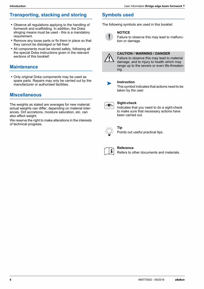
Symbols used
The following symbols are used in this booklet:
NOTICEFailure to observe this may lead to malfunc-tion or damage.
CAUTION / WARNING / DANGERFailure to observe this may lead to material damage, and to injury to health which may range up to the severe or even life-threaten-ing.
InstructionThis symbol indicates that actions need to be taken by the user.
Sight-checkIndicates that you need to do a sight-check to make sure that necessary actions have been carried out.
TipPoints out useful practical tips.
ReferenceRefers to other documents and materials.
User Information Bridge edge beam formwork T Introduction
7999770002 - 09/2018
Eurocodes at DokaIn Europe, a uniform series of Standards known as Eurocodes (EC) was developed for the construction field by the end of 2007. These are intended to provide a uniform basis, valid throughout Europe, for product specifications, tenders and mathematical verification.The EC are the world's most highly developed Stand-ards in the construction field.In the Doka Group, the EC are to be used as standard from the end of 2008. They will thus supersede the DIN norms as the "Doka standard" for product design.
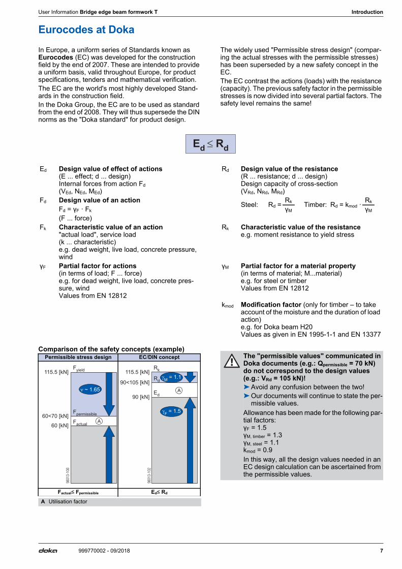
The widely used "Permissible stress design" (compar-ing the actual stresses with the permissible stresses) has been superseded by a new safety concept in the EC.The EC contrast the actions (loads) with the resistance (capacity). The previous safety factor in the permissible stresses is now divided into several partial factors. The safety level remains the same!
Comparison of the safety concepts (example)
Ed Design value of effect of actions (E ... effect; d ... design) Internal forces from action Fd (VEd, NEd, MEd)
Rd Design value of the resistance (R ... resistance; d ... design) Design capacity of cross-section (VRd, NRd, MRd)
Fd Design value of an action Steel: Rd =Rk Timber: Rd = kmod ·
Rk
Fd = γF · Fk γM γM
(F ... force)Fk Characteristic value of an action
"actual load", service load (k ... characteristic) e.g. dead weight, live load, concrete pressure, wind
Rk Characteristic value of the resistance e.g. moment resistance to yield stress
γF Partial factor for actions (in terms of load; F ... force) e.g. for dead weight, live load, concrete pres-sure, wind Values from EN 12812
γM Partial factor for a material property (in terms of material; M...material) e.g. for steel or timber Values from EN 12812
kmod Modification factor (only for timber – to take account of the moisture and the duration of load action) e.g. for Doka beam H20 Values as given in EN 1995-1-1 and EN 13377
Ed
Rd
Permissible stress design EC/DIN concept
Factual≤ Fpermissible Ed≤ Rd
A Utilisation factor
60 [kN]
60<70 [kN]
115.5 [kN]
� ~ 1.65
Fyield
Fpermissible
Factual
9801
3-10
0
A
90 [kN]
115.5 [kN]
90<105 [kN]
Rk
Rd
Ed
�M
= 1.1
�F
= 1.5
9801
3-10
2
A
The "permissible values" communicated in Doka documents (e.g.: Qpermissible = 70 kN) do not correspond to the design values (e.g.: VRd = 105 kN)!➤Avoid any confusion between the two!➤Our documents will continue to state the per-
missible values. Allowance has been made for the following par-tial factors: γF = 1.5 γM, timber = 1.3 γM, steel = 1.1 kmod = 0.9In this way, all the design values needed in an EC design calculation can be ascertained from the permissible values.

8 999770002 - 09/2018
Introduction User Information Bridge edge beam formwork T
Doka services
Support in every stage of the project
Doka offers a broad spectrum of services, all with a sin-gle aim: to help you succeed on the site.Every project is unique. Nevertheless, there is one thing that all construction projects have in common – and that is a basic structure with five stages. We at Doka know our clients' varying requirements. With our consulting, planning and other services, we help you achieve effective implementation of your formwork assignment using our formwork products – in every one of these stages.
Project Development Stage Bidding Stage Operations Scheduling Stage
Taking well-founded decisions thanks to professional advice and consulting
Optimising the preliminary work with Doka as an experienced part-ner
Controlled, regular forming oper-ations, for greater efficiency resulting from realistically calculated formwork concepts
Find precisely the right formwork solutions, with the aid of ▪ help with the bid invitation ▪ in-depth analysis of the initial sit-
uation ▪ objective evaluation of the plan-
ning, execution, and time-risks
Draw up potentially winning bids, by ▪ basing them on realistically calcu-
lated guideline prices ▪ making the right formwork
choices ▪ having an optimum time-calcula-
tion basis
Plan cost-effectively right from the outset, thanks to ▪ detailed offers ▪ determination of the commission-
ing quantities ▪ co-ordination of lead-times and
handover deadlines
1 2 3
User Information Bridge edge beam formwork T Introduction
9999770002 - 09/2018
The advantages for you thanks to professional advice and consulting
▪ Cost savings and time gains When we advise and support you right from the word 'go', we can make sure that the right formwork systems are chosen and then used as planned. This lets you achieve optimum utilisation of the formwork equipment, and effec-tive forming operations because your workflows will be correct.
▪ Maximised workplace safety The advice and support we can give you in how to use the equip-ment correctly, and as planned, leads to greater safety on the job.
▪ Transparency Because our services and costs are completely transparent, there is no need for improvisation dur-ing the project – and no unpleas-ant surprises at the end of it.
▪ Reduced close-out costs Our professional advice on the selection, quality and correct use of the equipment helps you avoid damage, and minimise wear-and-tear.
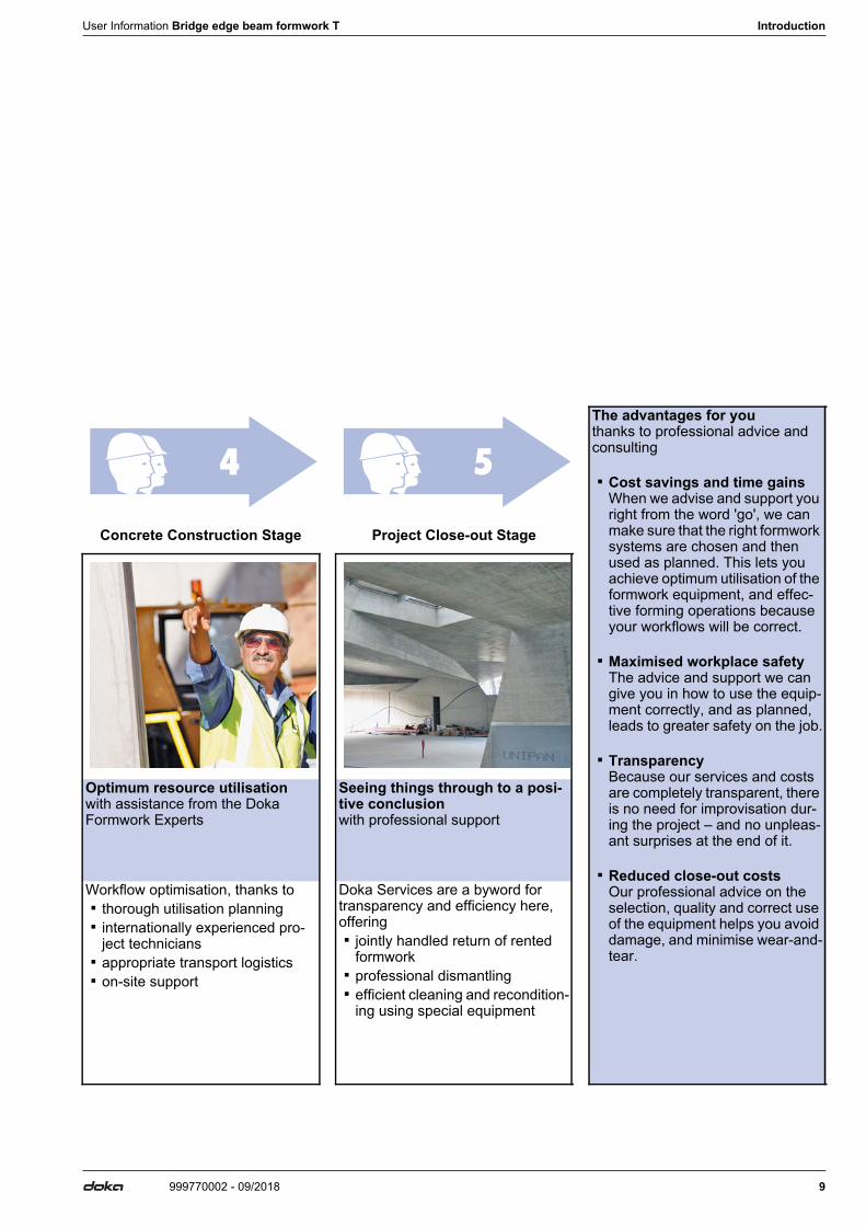
Concrete Construction Stage Project Close-out Stage
Optimum resource utilisation with assistance from the Doka Formwork Experts
Seeing things through to a posi-tive conclusion with professional support
Workflow optimisation, thanks to ▪ thorough utilisation planning ▪ internationally experienced pro-
ject technicians ▪ appropriate transport logistics ▪ on-site support
Doka Services are a byword for transparency and efficiency here, offering ▪ jointly handled return of rented
formwork ▪ professional dismantling ▪ efficient cleaning and recondition-
ing using special equipment
4 5
10 999770002 - 09/2018
System overview User Information Bridge edge beam formwork T
System overview
Bridge edge beam formwork T- the fast manual bridge edge beam formwork (type-tested)
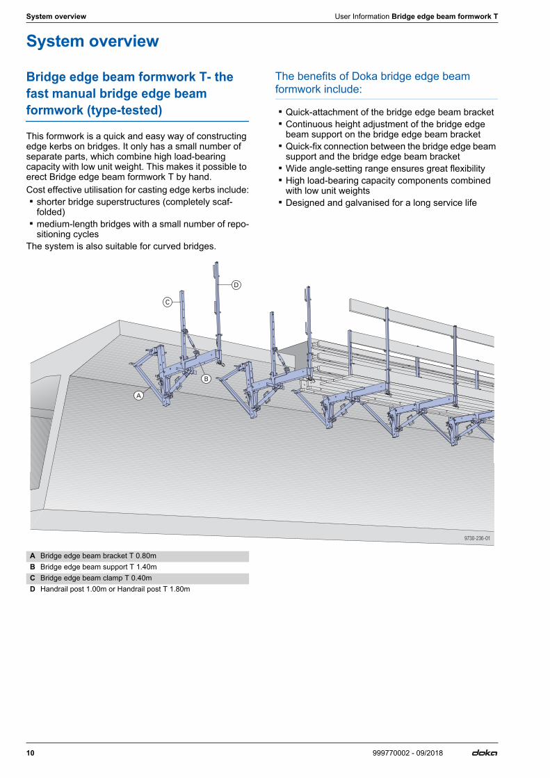
This formwork is a quick and easy way of constructing edge kerbs on bridges. It only has a small number of separate parts, which combine high load-bearing capacity with low unit weight. This makes it possible to erect Bridge edge beam formwork T by hand.Cost effective utilisation for casting edge kerbs include: ▪ shorter bridge superstructures (completely scaf-
folded) ▪ medium-length bridges with a small number of repo-
sitioning cyclesThe system is also suitable for curved bridges.
The benefits of Doka bridge edge beam formwork include:
▪ Quick-attachment of the bridge edge beam bracket ▪ Continuous height adjustment of the bridge edge
beam support on the bridge edge beam bracket ▪ Quick-fix connection between the bridge edge beam
support and the bridge edge beam bracket ▪ Wide angle-setting range ensures great flexibility ▪ High load-bearing capacity components combined
with low unit weights ▪ Designed and galvanised for a long service life
A Bridge edge beam bracket T 0.80mB Bridge edge beam support T 1.40mC Bridge edge beam clamp T 0.40mD Handrail post 1.00m or Handrail post T 1.80m
9730-236-01
A
B
C
D
User Information Bridge edge beam formwork T System overview
11999770002 - 09/2018
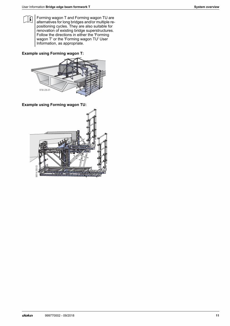
Example using Forming wagon T:
Example using Forming wagon TU:
Forming wagon T and Forming wagon TU are alternatives for long bridges and/or multiple re-positioning cycles. They are also suitable for renovation of existing bridge superstructures. Follow the directions in either the 'Forming wagon T' or the 'Forming wagon TU' User Information, as appropriate.
9730-235-01
9801
4-30
0-03
12 999770002 - 09/2018
Structural design User Information Bridge edge beam formwork T
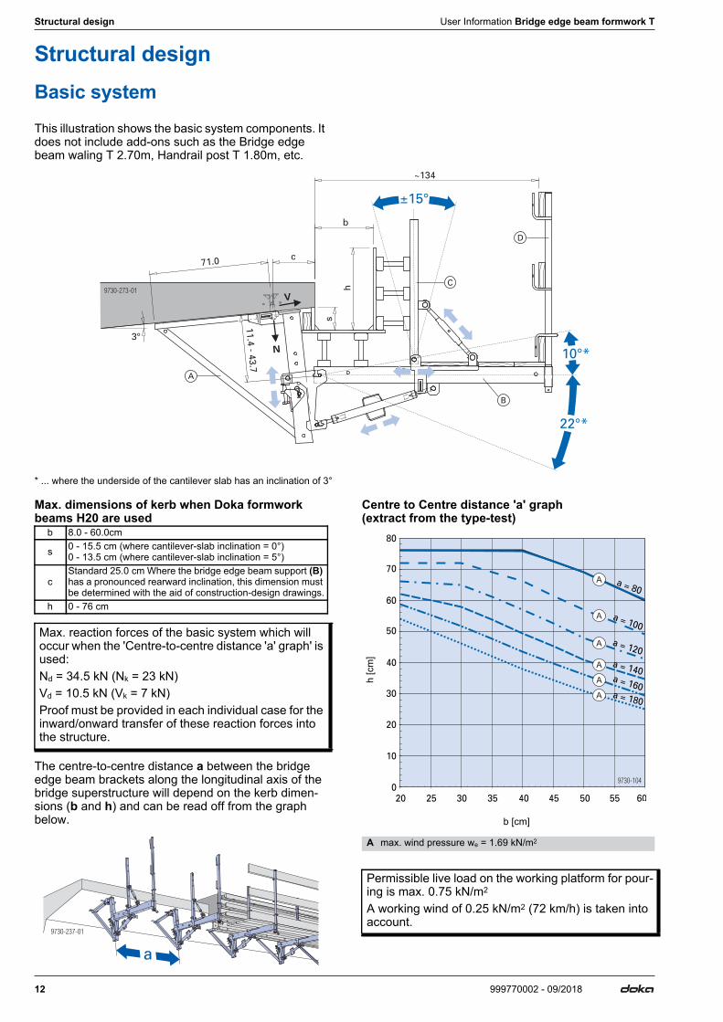
Structural designBasic systemThis illustration shows the basic system components. It does not include add-ons such as the Bridge edge beam waling T 2.70m, Handrail post T 1.80m, etc.
* ... where the underside of the cantilever slab has an inclination of 3°
Max. dimensions of kerb when Doka formwork beams H20 are used
The centre-to-centre distance a between the bridge edge beam brackets along the longitudinal axis of the bridge superstructure will depend on the kerb dimen-sions (b and h) and can be read off from the graph below.
Centre to Centre distance 'a' graph (extract from the type-test)
b 8.0 - 60.0cm
s 0 - 15.5 cm (where cantilever-slab inclination = 0°) 0 - 13.5 cm (where cantilever-slab inclination = 5°)
cStandard 25.0 cm Where the bridge edge beam support (B) has a pronounced rearward inclination, this dimension must be determined with the aid of construction-design drawings.
h 0 - 76 cm
Max. reaction forces of the basic system which will occur when the 'Centre-to-centre distance 'a' graph' is used:Nd = 34.5 kN (Nk = 23 kN)Vd = 10.5 kN (Vk = 7 kN)Proof must be provided in each individual case for the inward/onward transfer of these reaction forces into the structure.
9730-237-01
a
h [c
m]
b [cm]
A max. wind pressure we = 1.69 kN/m2
Permissible live load on the working platform for pour-ing is max. 0.75 kN/m2
A working wind of 0.25 kN/m2 (72 km/h) is taken into account.
A
A
A
A
A
A
User Information Bridge edge beam formwork T Structural design
13999770002 - 09/2018
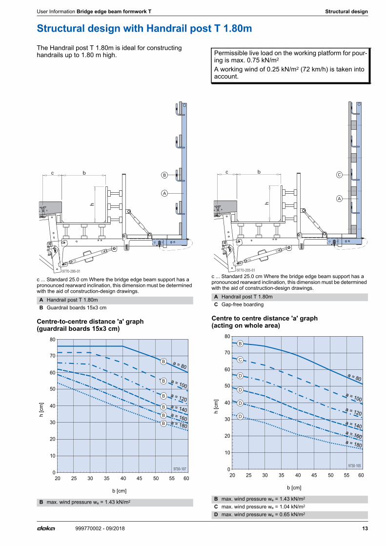
Structural design with Handrail post T 1.80mThe Handrail post T 1.80m is ideal for constructing handrails up to 1.80 m high.
c ... Standard 25.0 cm Where the bridge edge beam support has a pronounced rearward inclination, this dimension must be determined with the aid of construction-design drawings.
Centre-to-centre distance 'a' graph (guardrail boards 15x3 cm)
c ... Standard 25.0 cm Where the bridge edge beam support has a pronounced rearward inclination, this dimension must be determined with the aid of construction-design drawings.
Centre to centre distance 'a' graph (acting on whole area)
Permissible live load on the working platform for pour-ing is max. 0.75 kN/m2
A working wind of 0.25 kN/m2 (72 km/h) is taken into account.
A Handrail post T 1.80mB Guardrail boards 15x3 cm
h [c
m]
b [cm]
B max. wind pressure we = 1.43 kN/m2
b
h
9770-206-01
c
A
B
20 25 30 35 40 45 50 55 60
0
10
20
30
40
50
60
70
80
a = 80
a = 100
a = 120
a = 140a = 160a = 180
B
B
B
B
B
B
A Handrail post T 1.80mC Gap-free boarding
h [c
m]
b [cm]
B max. wind pressure we = 1.43 kN/m2
C max. wind pressure we = 1.04 kN/m2
D max. wind pressure we = 0.65 kN/m2
h
b
9770-205-01
c
A
C
20 25 30 35 40 45 50 55 60
0
10
20
30
40
50
60
70
80
a = 80
a = 100
a = 120
a = 140
a = 160
a = 180
B
C
D
D
D
D
14 999770002 - 09/2018
Instructions for assembly and use (Method statement) User Information Bridge edge beam formwork T
Instructions for assembly and use (Method statement)
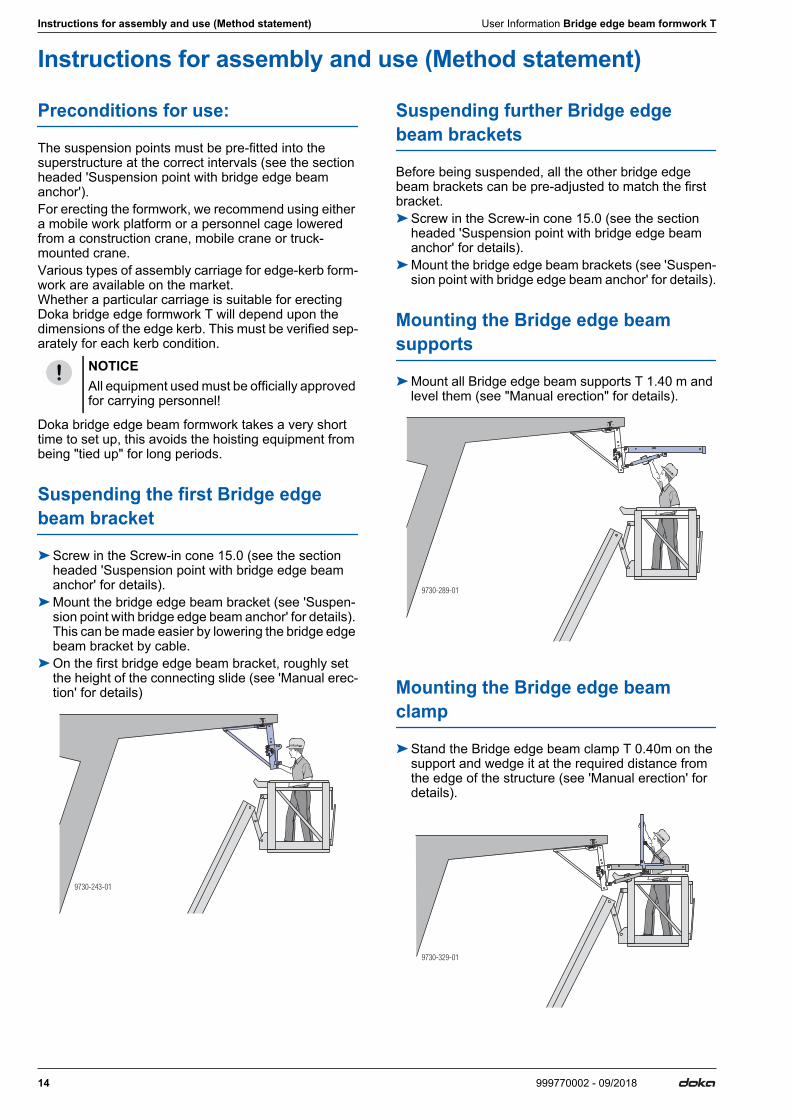
Preconditions for use:
The suspension points must be pre-fitted into the superstructure at the correct intervals (see the section headed 'Suspension point with bridge edge beam anchor').For erecting the formwork, we recommend using either a mobile work platform or a personnel cage lowered from a construction crane, mobile crane or truck-mounted crane.Various types of assembly carriage for edge-kerb form-work are available on the market. Whether a particular carriage is suitable for erecting Doka bridge edge formwork T will depend upon the dimensions of the edge kerb. This must be verified sep-arately for each kerb condition.
Doka bridge edge beam formwork takes a very short time to set up, this avoids the hoisting equipment from being "tied up" for long periods.
Suspending the first Bridge edge beam bracket
➤Screw in the Screw-in cone 15.0 (see the section headed 'Suspension point with bridge edge beam anchor' for details).
➤Mount the bridge edge beam bracket (see 'Suspen-sion point with bridge edge beam anchor' for details). This can be made easier by lowering the bridge edge beam bracket by cable.
➤On the first bridge edge beam bracket, roughly set the height of the connecting slide (see 'Manual erec-tion' for details)
Suspending further Bridge edge beam brackets
Before being suspended, all the other bridge edge beam brackets can be pre-adjusted to match the first bracket.➤Screw in the Screw-in cone 15.0 (see the section
headed 'Suspension point with bridge edge beam anchor' for details).
➤Mount the bridge edge beam brackets (see 'Suspen-sion point with bridge edge beam anchor' for details).
Mounting the Bridge edge beam supports
➤Mount all Bridge edge beam supports T 1.40 m and level them (see "Manual erection" for details).
Mounting the Bridge edge beam clamp
➤Stand the Bridge edge beam clamp T 0.40m on the support and wedge it at the required distance from the edge of the structure (see 'Manual erection' for details).
NOTICEAll equipment used must be officially approved for carrying personnel!
9730-243-01
9730-289-01
9730-329-01
User Information Bridge edge beam formwork T Instructions for assembly and use (Method statement)
15999770002 - 09/2018
Mounting the railing
➤Slot Handrail posts 1.00m into place, and fasten the guard-rail boards (see chapter "Manual erection" for details).
➤Lay the deck-boards (these must overlap by at least 20 cm).
Board thicknesses: ▪ floor decking min. 20x4 cm ▪ guard-rail boards min. 15/3 cm
Note:The plank and board thicknesses given here comply with the C24 category of EN 338.Observe all national regulations applying to deck-boards and guard-rail boards.
After this, no hoisting equipment is needed for any of the remaining operations.
Mounting the formwork
This is performed from the bridge superstructure on one side, and from the decking on the Bridge edge beam supports on the other.➤Mount the bottom formwork (see "Erecting the form-
work" for details).➤Mount the side-formwork (may be preassembled –
see "Erecting the formwork" for details).
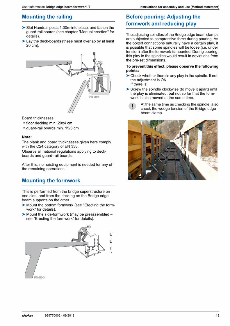
Before pouring: Adjusting the formwork and reducing play
The adjusting spindles of the Bridge edge beam clamps are subjected to compressive force during pouring. As the bolted connections naturally have a certain play, it is possible that some spindles will be loose (i.e. under tension) after the formwork is mounted. During pouring, this play in the spindles would result in deviations from the pre-set dimensions.To prevent this effect, please observe the following points:➤Check whether there is any play in the spindle. If not,
the adjustment is OK. If there is:
➤Screw the spindle clockwise (to move it apart) until the play is eliminated, but not so far that the form-work is also moved at the same time.9730-333-01
9730-292-01
At the same time as checking the spindle, also check the wedge tension of the Bridge edge beam clamp.
16 999770002 - 09/2018
Anchoring on the structure User Information Bridge edge beam formwork T
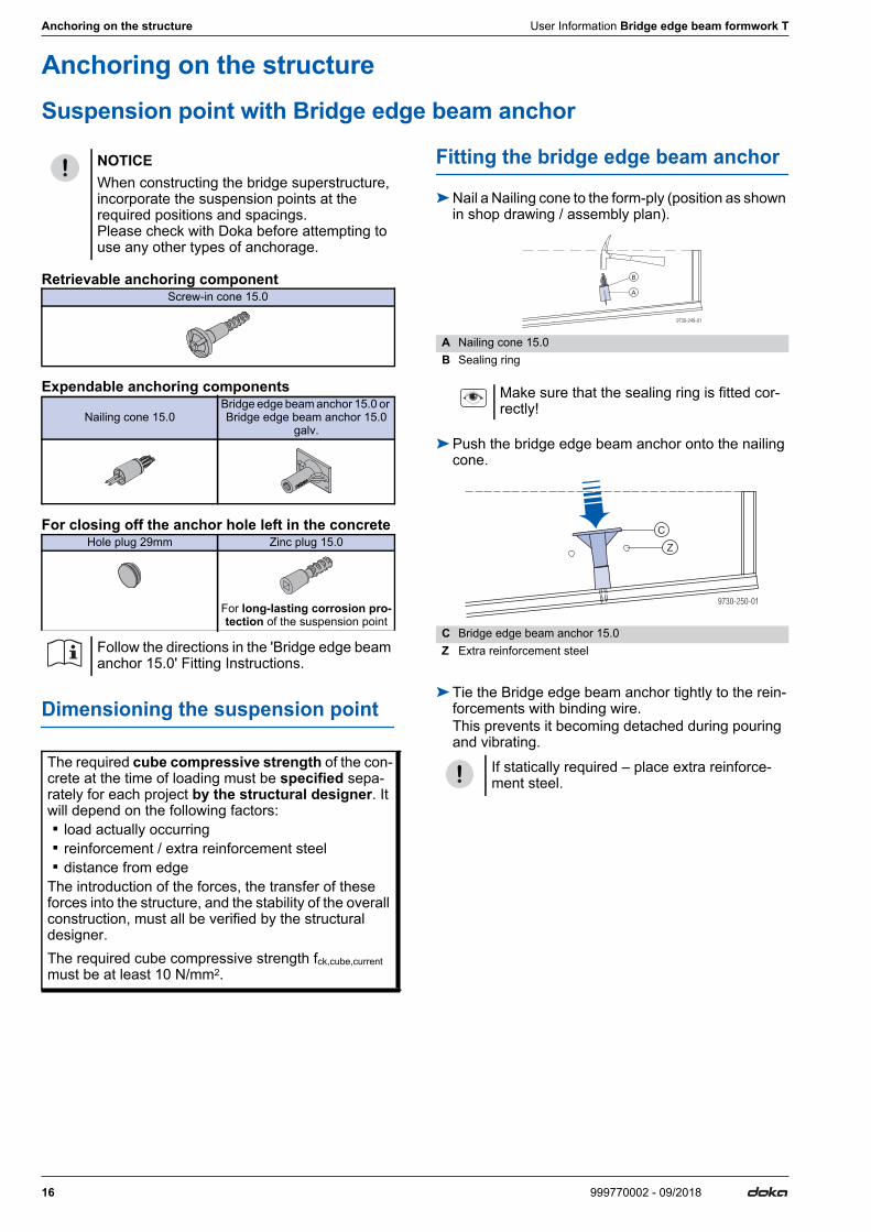
Anchoring on the structureSuspension point with Bridge edge beam anchor
Retrievable anchoring component
Expendable anchoring components
For closing off the anchor hole left in the concrete
Dimensioning the suspension point
Fitting the bridge edge beam anchor
➤Nail a Nailing cone to the form-ply (position as shown in shop drawing / assembly plan).
➤Push the bridge edge beam anchor onto the nailing cone.
➤Tie the Bridge edge beam anchor tightly to the rein-forcements with binding wire.This prevents it becoming detached during pouring and vibrating.
NOTICEWhen constructing the bridge superstructure, incorporate the suspension points at the required positions and spacings. Please check with Doka before attempting to use any other types of anchorage.
Screw-in cone 15.0
Nailing cone 15.0Bridge edge beam anchor 15.0 or Bridge edge beam anchor 15.0
galv.
Hole plug 29mm Zinc plug 15.0
For long-lasting corrosion pro-tection of the suspension point
Follow the directions in the 'Bridge edge beam anchor 15.0' Fitting Instructions.
The required cube compressive strength of the con-crete at the time of loading must be specified sepa-rately for each project by the structural designer. It will depend on the following factors: ▪ load actually occurring ▪ reinforcement / extra reinforcement steel ▪ distance from edgeThe introduction of the forces, the transfer of these forces into the structure, and the stability of the overall construction, must all be verified by the structural designer.The required cube compressive strength fck,cube,current must be at least 10 N/mm2.
A Nailing cone 15.0B Sealing ring
Make sure that the sealing ring is fitted cor-rectly!
C Bridge edge beam anchor 15.0Z Extra reinforcement steel
If statically required – place extra reinforce-ment steel.
9730-249-01
A
B
9730-250-01
C
Z
User Information Bridge edge beam formwork T Anchoring on the structure
17999770002 - 09/2018
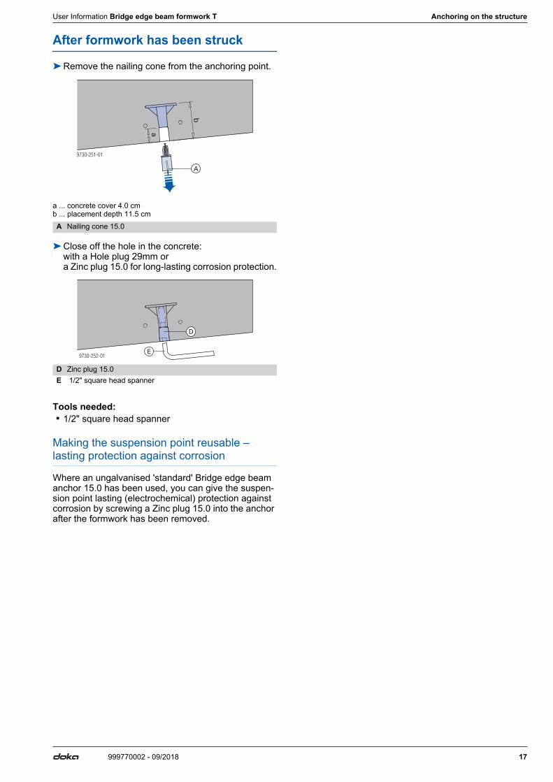
After formwork has been struck
➤Remove the nailing cone from the anchoring point.
a ... concrete cover 4.0 cmb ... placement depth 11.5 cm
➤Close off the hole in the concrete: with a Hole plug 29mm or a Zinc plug 15.0 for long-lasting corrosion protection.
Tools needed: ▪ 1/2" square head spanner
Making the suspension point reusable – lasting protection against corrosion
Where an ungalvanised 'standard' Bridge edge beam anchor 15.0 has been used, you can give the suspen-sion point lasting (electrochemical) protection against corrosion by screwing a Zinc plug 15.0 into the anchor after the formwork has been removed.
A Nailing cone 15.0
D Zinc plug 15.0E 1/2" square head spanner
9730-251-01
a
b
A
9730-252-01
D
E
18 999770002 - 09/2018
Anchoring on the structure User Information Bridge edge beam formwork T
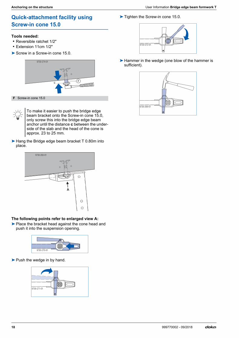
Quick-attachment facility using Screw-in cone 15.0
Tools needed: ▪ Reversible ratchet 1/2" ▪ Extension 11cm 1/2"➤Screw in a Screw-in cone 15.0.
➤Hang the Bridge edge beam bracket T 0.80m into place.
The following points refer to enlarged view A:➤Place the bracket head against the cone head and
push it into the suspension opening.
➤Push the wedge in by hand.
➤Tighten the Screw-in cone 15.0.
➤Hammer in the wedge (one blow of the hammer is sufficient).
F Screw-in cone 15.0
To make it easier to push the bridge edge beam bracket onto the Screw-in cone 15.0, only screw this into the bridge edge beam anchor until the distance c between the under-side of the slab and the head of the cone is approx. 23 to 25 mm.
c
9730-274-01
F
9730-283-01
A
9730-270-01
9730-271-01
9730-272-01
9730-269-01
User Information Bridge edge beam formwork T Anchoring on the structure
19999770002 - 09/2018
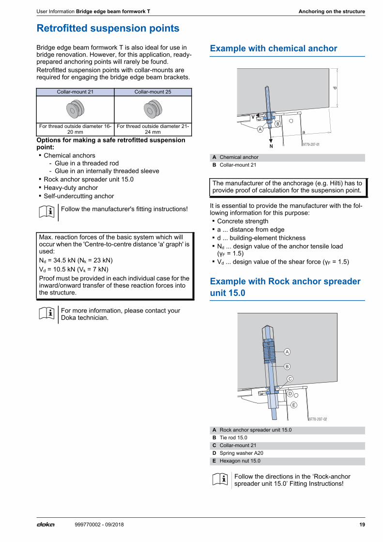
Retrofitted suspension pointsBridge edge beam formwork T is also ideal for use in bridge renovation. However, for this application, ready-prepared anchoring points will rarely be found.Retrofitted suspension points with collar-mounts are required for engaging the bridge edge beam brackets.
Options for making a safe retrofitted suspension point: ▪ Chemical anchors
- Glue in a threaded rod- Glue in an internally threaded sleeve
▪ Rock anchor spreader unit 15.0 ▪ Heavy-duty anchor ▪ Self-undercutting anchor
Example with chemical anchor
It is essential to provide the manufacturer with the fol-lowing information for this purpose: ▪ Concrete strength ▪ a ... distance from edge ▪ d ... building-element thickness ▪ Nd ... design value of the anchor tensile load
(γF = 1.5) ▪ Vd ... design value of the shear force (γF = 1.5)
Example with Rock anchor spreader unit 15.0
Collar-mount 21 Collar-mount 25
For thread outside diameter 16-20 mm
For thread outside diameter 21-24 mm
Follow the manufacturer's fitting instructions!
Max. reaction forces of the basic system which will occur when the 'Centre-to-centre distance 'a' graph' is used:Nd = 34.5 kN (Nk = 23 kN)Vd = 10.5 kN (Vk = 7 kN)Proof must be provided in each individual case for the inward/onward transfer of these reaction forces into the structure.
For more information, please contact your Doka technician.
A Chemical anchorB Collar-mount 21
The manufacturer of the anchorage (e.g. Hilti) has to provide proof of calculation for the suspension point.
A Rock anchor spreader unit 15.0B Tie rod 15.0C Collar-mount 21D Spring washer A20E Hexagon nut 15.0
Follow the directions in the ‘Rock-anchor spreader unit 15.0’ Fitting Instructions!
d
a
N
V
B
A
C
D
E
20 999770002 - 09/2018
Assembly User Information Bridge edge beam formwork T
AssemblyManual erection
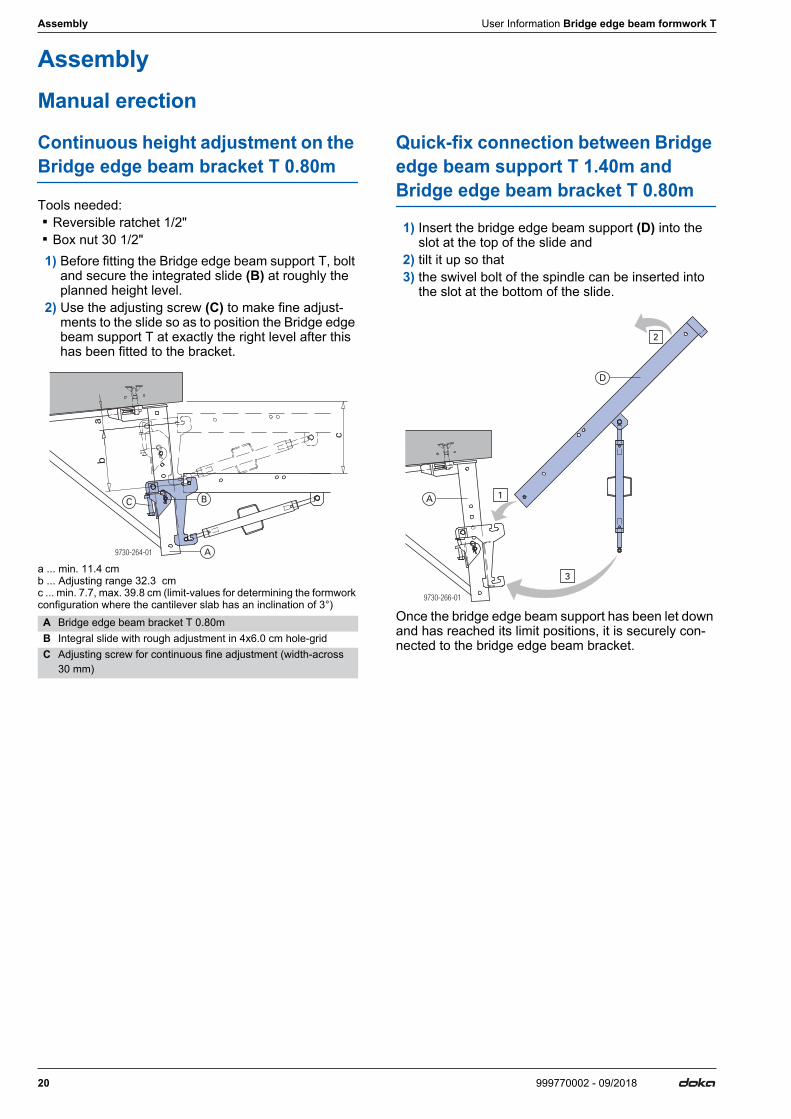
Continuous height adjustment on the Bridge edge beam bracket T 0.80m
Tools needed: ▪ Reversible ratchet 1/2" ▪ Box nut 30 1/2"1) Before fitting the Bridge edge beam support T, bolt
and secure the integrated slide (B) at roughly the planned height level.
2) Use the adjusting screw (C) to make fine adjust-ments to the slide so as to position the Bridge edge beam support T at exactly the right level after this has been fitted to the bracket.
a ... min. 11.4 cmb ... Adjusting range 32.3 cmc ... min. 7.7, max. 39.8 cm (limit-values for determining the formwork configuration where the cantilever slab has an inclination of 3°)
Quick-fix connection between Bridge edge beam support T 1.40m and Bridge edge beam bracket T 0.80m
1) Insert the bridge edge beam support (D) into the slot at the top of the slide and
2) tilt it up so that3) the swivel bolt of the spindle can be inserted into
the slot at the bottom of the slide.
Once the bridge edge beam support has been let down and has reached its limit positions, it is securely con-nected to the bridge edge beam bracket.
A Bridge edge beam bracket T 0.80mB Integral slide with rough adjustment in 4x6.0 cm hole-gridC Adjusting screw for continuous fine adjustment (width-across
30 mm)
9730-264-01
ba
c
A
BC
9730-266-01
1
2
3
A
D
User Information Bridge edge beam formwork T Assembly
21999770002 - 09/2018
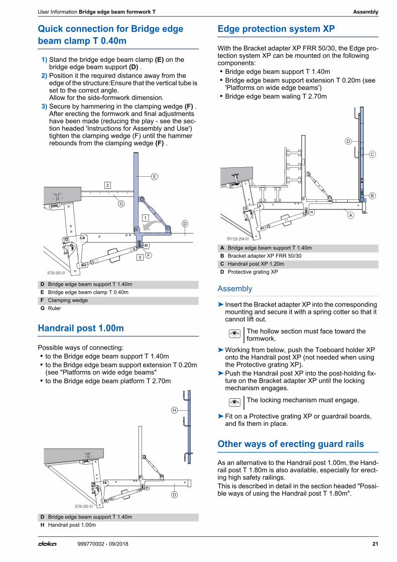
Quick connection for Bridge edge beam clamp T 0.40m
1) Stand the bridge edge beam clamp (E) on the bridge edge beam support (D) .
2) Position it the required distance away from the edge of the structure:Ensure that the vertical tube is set to the correct angle. Allow for the side-formwork dimension.
3) Secure by hammering in the clamping wedge (F) . After erecting the formwork and final adjustments have been made (reducing the play - see the sec-tion headed 'Instructions for Assembly and Use') tighten the clamping wedge (F) until the hammer rebounds from the clamping wedge (F) .
Handrail post 1.00m
Possible ways of connecting: ▪ to the Bridge edge beam support T 1.40m ▪ to the Bridge edge beam support extension T 0.20m
(see "Platforms on wide edge beams" ▪ to the Bridge edge beam platform T 2.70m
Edge protection system XP
With the Bracket adapter XP FRR 50/30, the Edge pro-tection system XP can be mounted on the following components: ▪ Bridge edge beam support T 1.40m ▪ Bridge edge beam support extension T 0.20m (see
'Platforms on wide edge beams') ▪ Bridge edge beam waling T 2.70m
Assembly
➤ Insert the Bracket adapter XP into the corresponding mounting and secure it with a spring cotter so that it cannot lift out.
➤Working from below, push the Toeboard holder XP onto the Handrail post XP (not needed when using the Protective grating XP).
➤Push the Handrail post XP into the post-holding fix-ture on the Bracket adapter XP until the locking mechanism engages.
➤Fit on a Protective grating XP or guardrail boards, and fix them in place.
Other ways of erecting guard rails
As an alternative to the Handrail post 1.00m, the Hand-rail post T 1.80m is also available, especially for erect-ing high safety railings.This is described in detail in the section headed "Possi-ble ways of using the Handrail post T 1.80m".
D Bridge edge beam support T 1.40mE Bridge edge beam clamp T 0.40mF Clamping wedgeG Ruler
D Bridge edge beam support T 1.40mH Handrail post 1.00m
9730-265-01
1
2
3
E
F
G
D
9730-285-01
H
D
A Bridge edge beam support T 1.40mB Bracket adapter XP FRR 50/30C Handrail post XP 1.20mD Protective grating XP
The hollow section must face toward the formwork.
The locking mechanism must engage.
B
C
D
A
22 999770002 - 09/2018
Assembly User Information Bridge edge beam formwork T
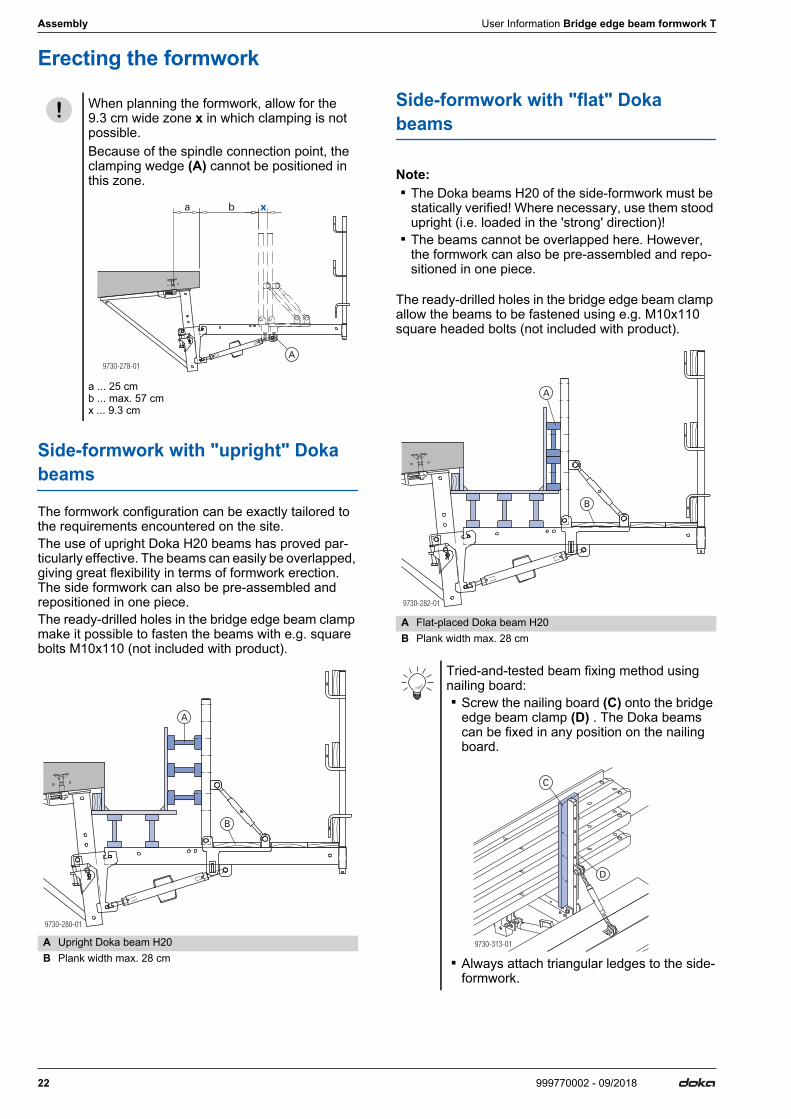
Erecting the formwork
Side-formwork with "upright" Doka beams
The formwork configuration can be exactly tailored to the requirements encountered on the site.The use of upright Doka H20 beams has proved par-ticularly effective. The beams can easily be overlapped, giving great flexibility in terms of formwork erection. The side formwork can also be pre-assembled and repositioned in one piece.The ready-drilled holes in the bridge edge beam clamp make it possible to fasten the beams with e.g. square bolts M10x110 (not included with product).
Side-formwork with "flat" Doka beams
Note: ▪ The Doka beams H20 of the side-formwork must be
statically verified! Where necessary, use them stood upright (i.e. loaded in the 'strong' direction)!
▪ The beams cannot be overlapped here. However, the formwork can also be pre-assembled and repo-sitioned in one piece.
The ready-drilled holes in the bridge edge beam clamp allow the beams to be fastened using e.g. M10x110 square headed bolts (not included with product).
When planning the formwork, allow for the 9.3 cm wide zone x in which clamping is not possible.Because of the spindle connection point, the clamping wedge (A) cannot be positioned in this zone.
a ... 25 cmb ... max. 57 cmx ... 9.3 cm
A Upright Doka beam H20B Plank width max. 28 cm
9730-278-01
a xb
A
9730-280-01
A
B
A Flat-placed Doka beam H20B Plank width max. 28 cm
Tried-and-tested beam fixing method using nailing board: ▪ Screw the nailing board (C) onto the bridge
edge beam clamp (D) . The Doka beams can be fixed in any position on the nailing board.
▪ Always attach triangular ledges to the side-formwork.
9730-282-01
A
B
9730-313-01
C
D
User Information Bridge edge beam formwork T Additional areas of use
23999770002 - 09/2018
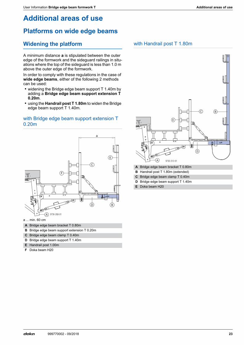
Additional areas of usePlatforms on wide edge beams
Widening the platform
A minimum distance a is stipulated between the outer edge of the formwork and the sideguard railings in situ-ations where the top of the sideguard is less than 1.0 m above the outer edge of the formwork.In order to comply with these regulations in the case of wide edge beams, either of the following 2 methods can be used: ▪ widening the Bridge edge beam support T 1.40m by
adding a Bridge edge beam support extension T 0.20m.
▪ using the Handrail post T 1.80m to widen the Bridge edge beam support T 1.40m.
with Bridge edge beam support extension T 0.20m
a ... min. 60 cm
with Handrail post T 1.80m
A Bridge edge beam bracket T 0.80mB Bridge edge beam support extension T 0.20mC Bridge edge beam clamp T 0.40mD Bridge edge beam support T 1.40mE Handrail post 1.00mF Doka beam H20
9730-268-01
a
E
F
D B
A
C A Bridge edge beam bracket T 0.80mB Handrail post T 1.80m (extended)C Bridge edge beam clamp T 0.40mD Bridge edge beam support T 1.40mE Doka beam H20
9730-312-01A
BC
D
E
24 999770002 - 09/2018
Additional areas of use User Information Bridge edge beam formwork T
Possible ways of using the Handrail post T 1.80m
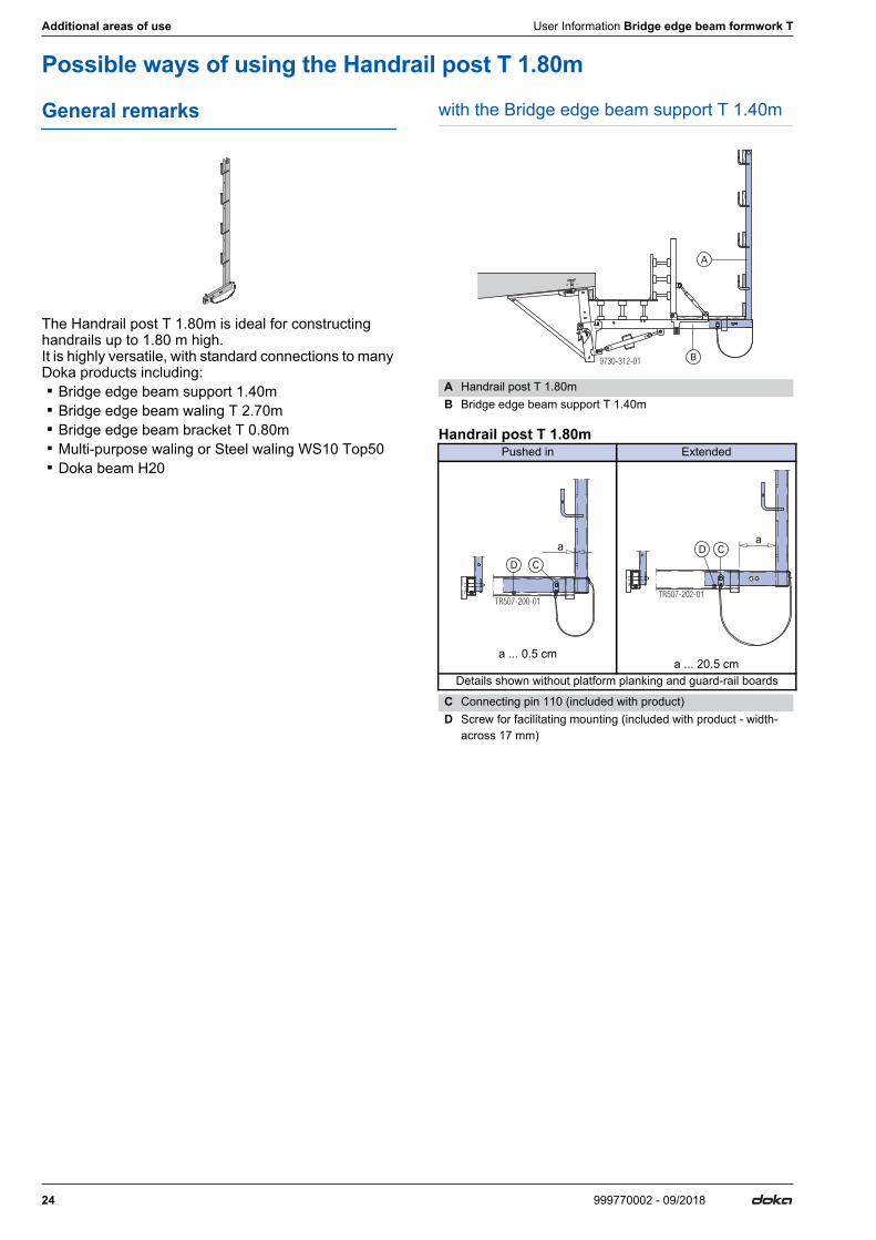
General remarks
The Handrail post T 1.80m is ideal for constructing handrails up to 1.80 m high. It is highly versatile, with standard connections to many Doka products including: ▪ Bridge edge beam support 1.40m ▪ Bridge edge beam waling T 2.70m ▪ Bridge edge beam bracket T 0.80m ▪ Multi-purpose waling or Steel waling WS10 Top50 ▪ Doka beam H20
with the Bridge edge beam support T 1.40m
Handrail post T 1.80m
A Handrail post T 1.80mB Bridge edge beam support T 1.40m
Pushed in Extended
a ... 0.5 cma ... 20.5 cm
Details shown without platform planking and guard-rail boards
C Connecting pin 110 (included with product)D Screw for facilitating mounting (included with product - width-
across 17 mm)
9730-312-01
A
B
TR507-200-01
a
CD
TR507-202-01
CDa
User Information Bridge edge beam formwork T Additional areas of use
25999770002 - 09/2018
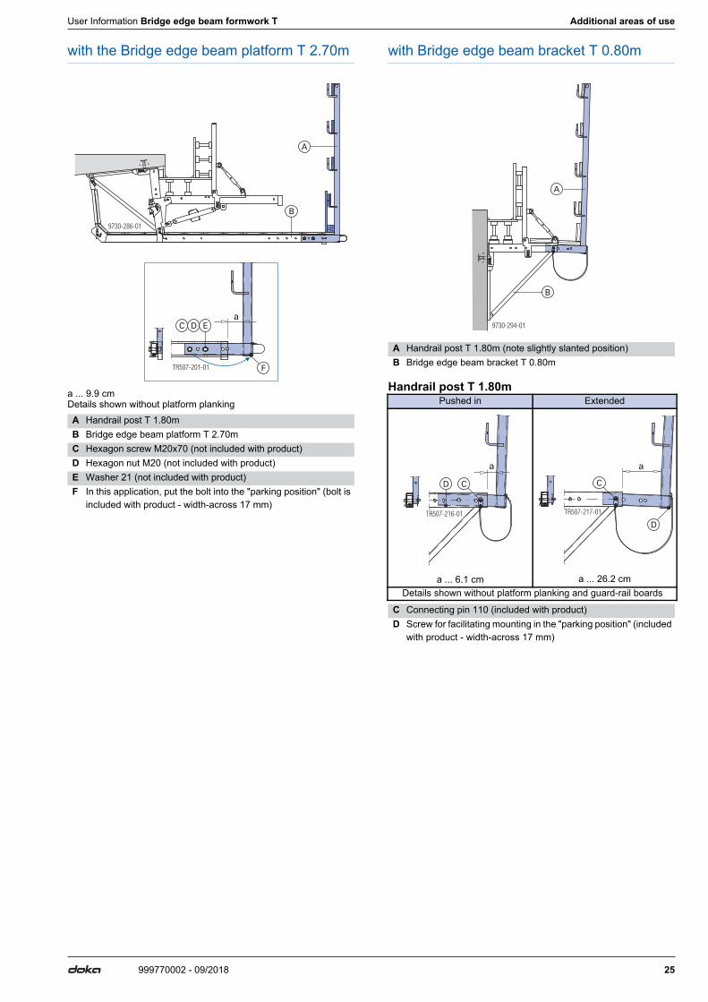
with the Bridge edge beam platform T 2.70m
a ... 9.9 cmDetails shown without platform planking
with Bridge edge beam bracket T 0.80m
Handrail post T 1.80m
A Handrail post T 1.80mB Bridge edge beam platform T 2.70mC Hexagon screw M20x70 (not included with product)D Hexagon nut M20 (not included with product)E Washer 21 (not included with product)F In this application, put the bolt into the "parking position" (bolt is
included with product - width-across 17 mm)
9730-286-01
B
A
TR507-201-01
aC D E
F
A Handrail post T 1.80m (note slightly slanted position)B Bridge edge beam bracket T 0.80m
Pushed in Extended
a ... 6.1 cm a ... 26.2 cmDetails shown without platform planking and guard-rail boards
C Connecting pin 110 (included with product)D Screw for facilitating mounting in the "parking position" (included
with product - width-across 17 mm)
9730-294-01
B
A
TR507-216-01
a
CD
TR507-217-01
a
C
D
26 999770002 - 09/2018
Additional areas of use User Information Bridge edge beam formwork T
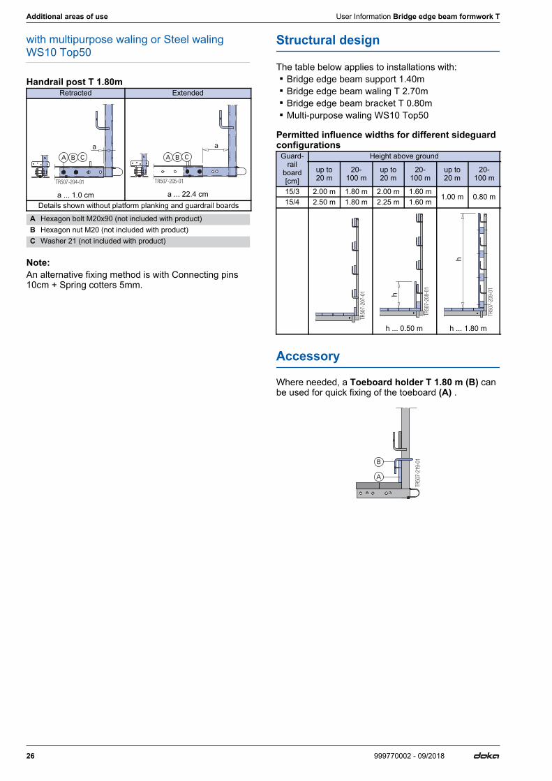
with multipurpose waling or Steel waling WS10 Top50
Handrail post T 1.80m
Note:An alternative fixing method is with Connecting pins 10cm + Spring cotters 5mm.
Structural design
The table below applies to installations with: ▪ Bridge edge beam support 1.40m ▪ Bridge edge beam waling T 2.70m ▪ Bridge edge beam bracket T 0.80m ▪ Multi-purpose waling WS10 Top50
Permitted influence widths for different sideguard configurations
Accessory
Where needed, a Toeboard holder T 1.80 m (B) can be used for quick fixing of the toeboard (A) .
Retracted Extended
a ... 1.0 cm a ... 22.4 cmDetails shown without platform planking and guardrail boards
A Hexagon bolt M20x90 (not included with product)B Hexagon nut M20 (not included with product)C Washer 21 (not included with product)
TR507-204-01
aA B C
TR507-205-01
a
A B C Guard-rail
board [cm]
Height above ground
up to 20 m
20- 100 m
up to 20 m
20- 100 m
up to 20 m
20- 100 m
15/3 2.00 m 1.80 m 2.00 m 1.60 m1.00 m 0.80 m
15/4 2.50 m 1.80 m 2.25 m 1.60 m
h ... 0.50 m h ... 1.80 m
TR50
7-20
7-01
TR50
7-20
8-01
h
TR50
7-20
9-01
h
TR50
7-21
9-01
A
B

User Information Bridge edge beam formwork T Additional areas of use
27999770002 - 09/2018
28 999770002 - 09/2018
Additional areas of use User Information Bridge edge beam formwork T
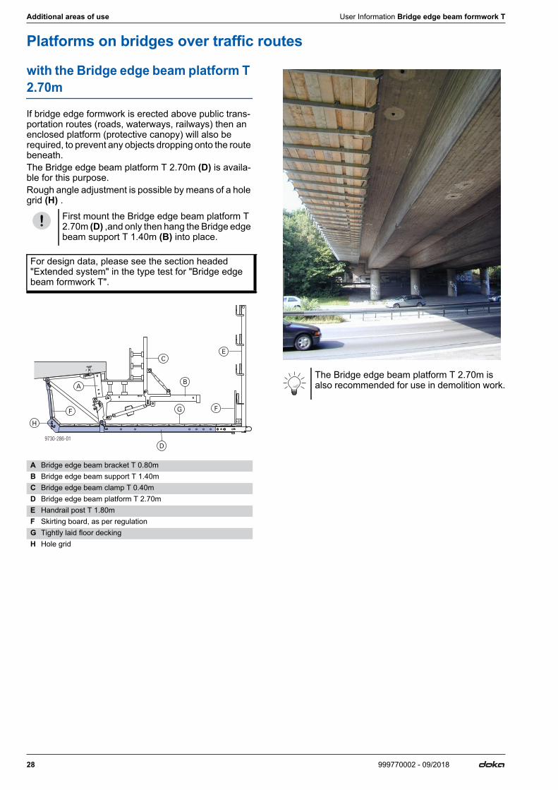
Platforms on bridges over traffic routes
with the Bridge edge beam platform T 2.70m
If bridge edge formwork is erected above public trans-portation routes (roads, waterways, railways) then an enclosed platform (protective canopy) will also be required, to prevent any objects dropping onto the route beneath. The Bridge edge beam platform T 2.70m (D) is availa-ble for this purpose.Rough angle adjustment is possible by means of a hole grid (H) .
First mount the Bridge edge beam platform T 2.70m (D) ,and only then hang the Bridge edge beam support T 1.40m (B) into place.
For design data, please see the section headed "Extended system" in the type test for "Bridge edge beam formwork T".
A Bridge edge beam bracket T 0.80mB Bridge edge beam support T 1.40mC Bridge edge beam clamp T 0.40mD Bridge edge beam platform T 2.70mE Handrail post T 1.80mF Skirting board, as per regulationG Tightly laid floor deckingH Hole grid
9730-286-01
A
H
E
FF
C
D
G
BThe Bridge edge beam platform T 2.70m is also recommended for use in demolition work.
User Information Bridge edge beam formwork T Additional areas of use
29999770002 - 09/2018
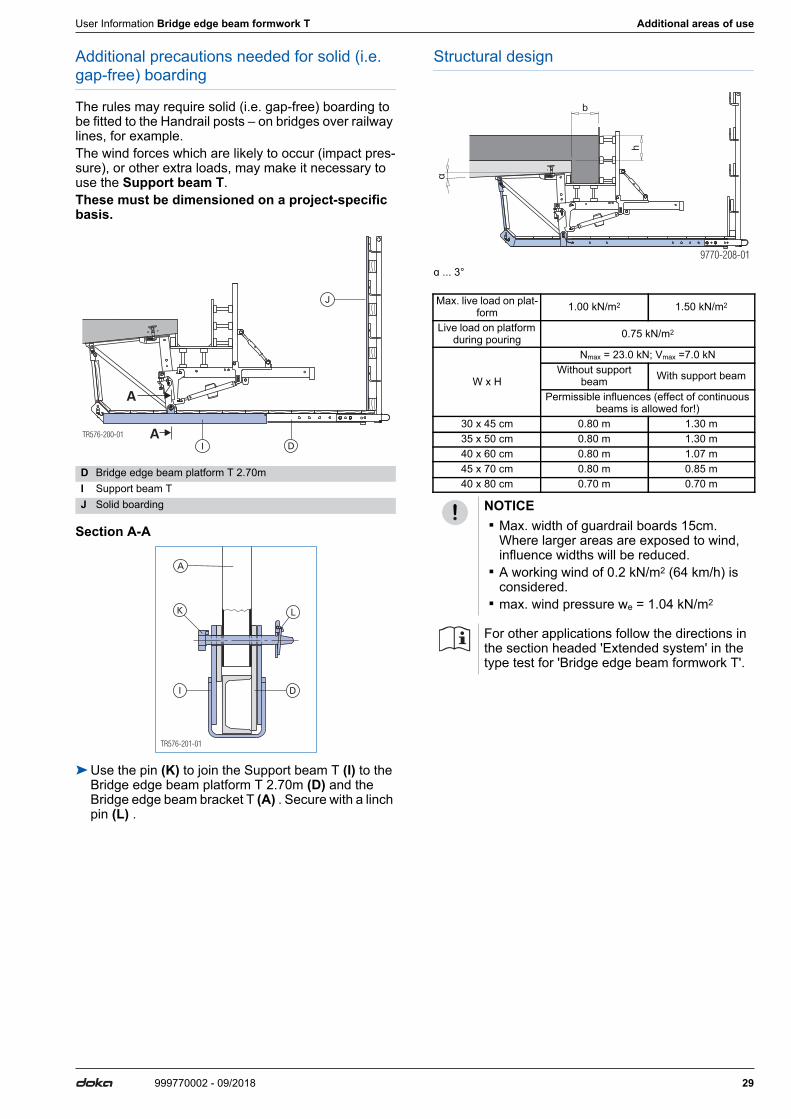
Additional precautions needed for solid (i.e. gap-free) boarding
The rules may require solid (i.e. gap-free) boarding to be fitted to the Handrail posts – on bridges over railway lines, for example.The wind forces which are likely to occur (impact pres-sure), or other extra loads, may make it necessary to use the Support beam T.These must be dimensioned on a project-specific basis.
Section A-A
➤Use the pin (K) to join the Support beam T (I) to the Bridge edge beam platform T 2.70m (D) and the Bridge edge beam bracket T (A) . Secure with a linch pin (L) .
Structural design
ɑ ... 3°
D Bridge edge beam platform T 2.70mI Support beam TJ Solid boarding
TR576-200-01 A
A
D
J
I
TR576-201-01
L
DI
A
K
Max. live load on plat-form 1.00 kN/m2 1.50 kN/m2
Live load on platform during pouring 0.75 kN/m2
W x H
Nmax = 23.0 kN; Vmax =7.0 kNWithout support
beam With support beam
Permissible influences (effect of continuous beams is allowed for!)
30 x 45 cm 0.80 m 1.30 m35 x 50 cm 0.80 m 1.30 m40 x 60 cm 0.80 m 1.07 m45 x 70 cm 0.80 m 0.85 m40 x 80 cm 0.70 m 0.70 m
NOTICE ▪ Max. width of guardrail boards 15cm.
Where larger areas are exposed to wind, influence widths will be reduced.
▪ A working wind of 0.2 kN/m2 (64 km/h) is considered.
▪ max. wind pressure we = 1.04 kN/m2
For other applications follow the directions in the section headed 'Extended system' in the type test for 'Bridge edge beam formwork T'.
b
h
α
30 999770002 - 09/2018
Additional areas of use User Information Bridge edge beam formwork T
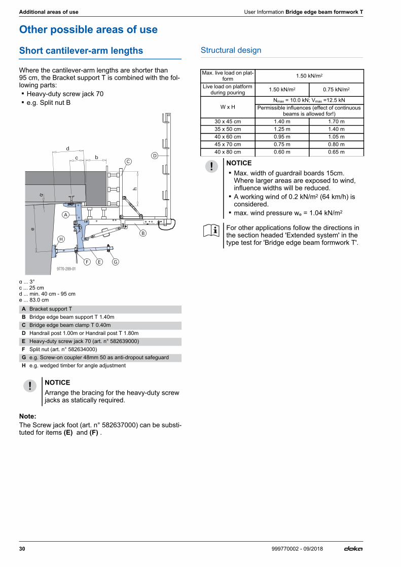
Other possible areas of use
Short cantilever-arm lengths
Where the cantilever-arm lengths are shorter than 95 cm, the Bracket support T is combined with the fol-lowing parts: ▪ Heavy-duty screw jack 70 ▪ e.g. Split nut B
ɑ ... 3°c ... 25 cmd ... min. 40 cm - 95 cme ... 83.0 cm
Note:The Screw jack foot (art. n° 582637000) can be substi-tuted for items (E) and (F) .
Structural design
A Bracket support TB Bridge edge beam support T 1.40mC Bridge edge beam clamp T 0.40mD Handrail post 1.00m or Handrail post T 1.80mE Heavy-duty screw jack 70 (art. n° 582639000)F Split nut (art. n° 582634000)G e.g. Screw-on coupler 48mm 50 as anti-dropout safeguardH e.g. wedged timber for angle adjustment
NOTICEArrange the bracing for the heavy-duty screw jacks as statically required.
α
Max. live load on plat-form 1.50 kN/m2
Live load on platform during pouring 1.50 kN/m2 0.75 kN/m2
W x HNmax = 10.0 kN; Vmax =12.5 kN
Permissible influences (effect of continuous beams is allowed for!)
30 x 45 cm 1.40 m 1.70 m35 x 50 cm 1.25 m 1.40 m40 x 60 cm 0.95 m 1.05 m45 x 70 cm 0.75 m 0.80 m40 x 80 cm 0.60 m 0.65 m
NOTICE ▪ Max. width of guardrail boards 15cm.
Where larger areas are exposed to wind, influence widths will be reduced.
▪ A working wind of 0.2 kN/m2 (64 km/h) is considered.
▪ max. wind pressure we = 1.04 kN/m2
For other applications follow the directions in the section headed 'Extended system' in the type test for 'Bridge edge beam formwork T'.
User Information Bridge edge beam formwork T Additional areas of use
31999770002 - 09/2018
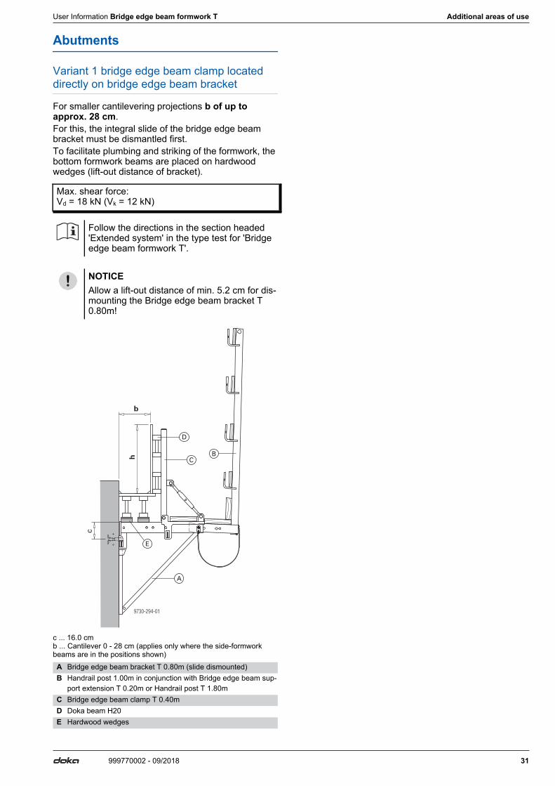
Abutments
Variant 1 bridge edge beam clamp located directly on bridge edge beam bracket
For smaller cantilevering projections b of up to approx. 28 cm.For this, the integral slide of the bridge edge beam bracket must be dismantled first.To facilitate plumbing and striking of the formwork, the bottom formwork beams are placed on hardwood wedges (lift-out distance of bracket).
c ... 16.0 cmb ... Cantilever 0 - 28 cm (applies only where the side-formwork beams are in the positions shown)
Max. shear force: Vd = 18 kN (Vk = 12 kN)
Follow the directions in the section headed 'Extended system' in the type test for 'Bridge edge beam formwork T'.
NOTICEAllow a lift-out distance of min. 5.2 cm for dis-mounting the Bridge edge beam bracket T 0.80m!
A Bridge edge beam bracket T 0.80m (slide dismounted)B Handrail post 1.00m in conjunction with Bridge edge beam sup-
port extension T 0.20m or Handrail post T 1.80mC Bridge edge beam clamp T 0.40mD Doka beam H20E Hardwood wedges
9730-294-01
b
h
c
A
BC
D
E
32 999770002 - 09/2018
Additional areas of use User Information Bridge edge beam formwork T
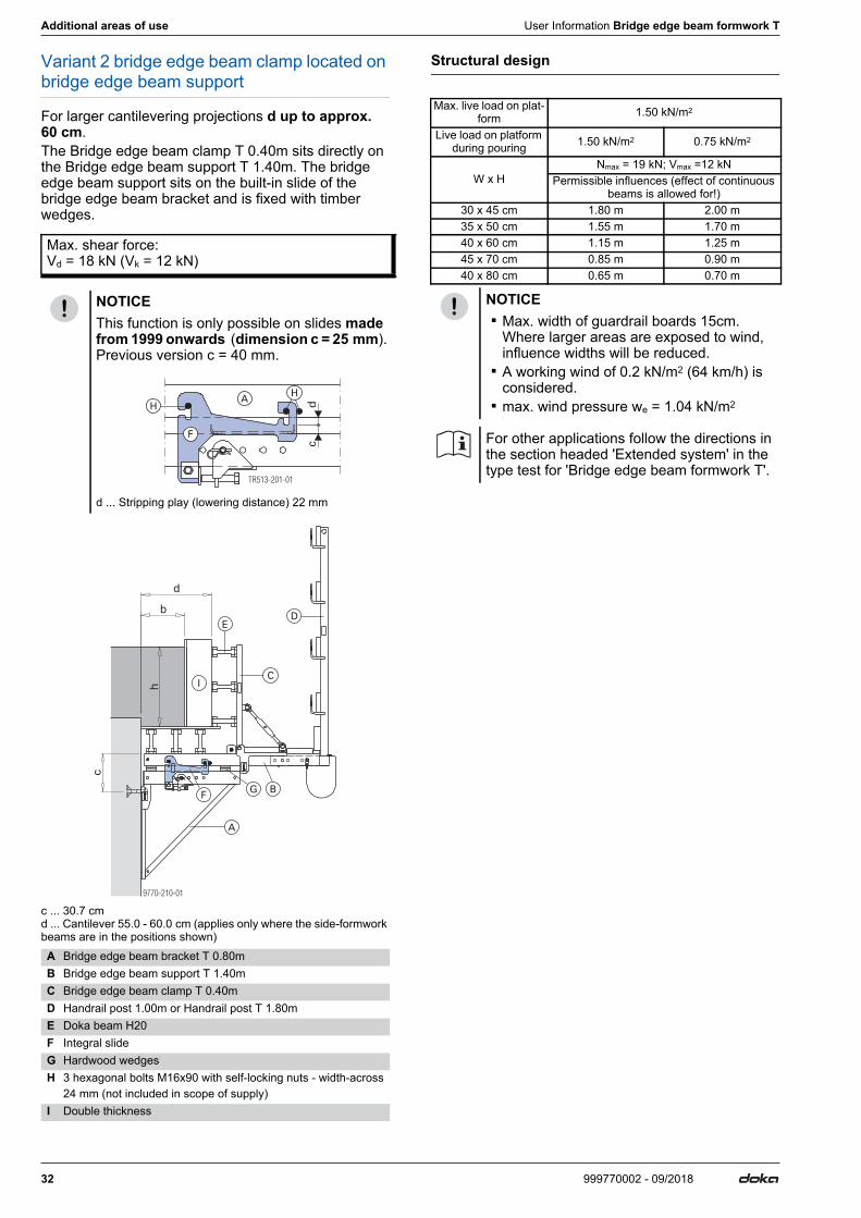
Variant 2 bridge edge beam clamp located on bridge edge beam support
For larger cantilevering projections d up to approx. 60 cm.The Bridge edge beam clamp T 0.40m sits directly on the Bridge edge beam support T 1.40m. The bridge edge beam support sits on the built-in slide of the bridge edge beam bracket and is fixed with timber wedges.
c ... 30.7 cmd ... Cantilever 55.0 - 60.0 cm (applies only where the side-formwork beams are in the positions shown)
Structural design
Max. shear force: Vd = 18 kN (Vk = 12 kN)
NOTICEThis function is only possible on slides made from 1999 onwards (dimension c = 25 mm). Previous version c = 40 mm.
d ... Stripping play (lowering distance) 22 mm
A Bridge edge beam bracket T 0.80mB Bridge edge beam support T 1.40mC Bridge edge beam clamp T 0.40mD Handrail post 1.00m or Handrail post T 1.80mE Doka beam H20F Integral slideG Hardwood wedgesH 3 hexagonal bolts M16x90 with self-locking nuts - width-across
24 mm (not included in scope of supply)I Double thickness
TR513-201-01
cdA
F
HH
c
b
h
d
Max. live load on plat-form 1.50 kN/m2
Live load on platform during pouring 1.50 kN/m2 0.75 kN/m2
W x HNmax = 19 kN; Vmax =12 kN
Permissible influences (effect of continuous beams is allowed for!)
30 x 45 cm 1.80 m 2.00 m35 x 50 cm 1.55 m 1.70 m40 x 60 cm 1.15 m 1.25 m45 x 70 cm 0.85 m 0.90 m40 x 80 cm 0.65 m 0.70 m
NOTICE ▪ Max. width of guardrail boards 15cm.
Where larger areas are exposed to wind, influence widths will be reduced.
▪ A working wind of 0.2 kN/m2 (64 km/h) is considered.
▪ max. wind pressure we = 1.04 kN/m2
For other applications follow the directions in the section headed 'Extended system' in the type test for 'Bridge edge beam formwork T'.
User Information Bridge edge beam formwork T Additional areas of use
33999770002 - 09/2018
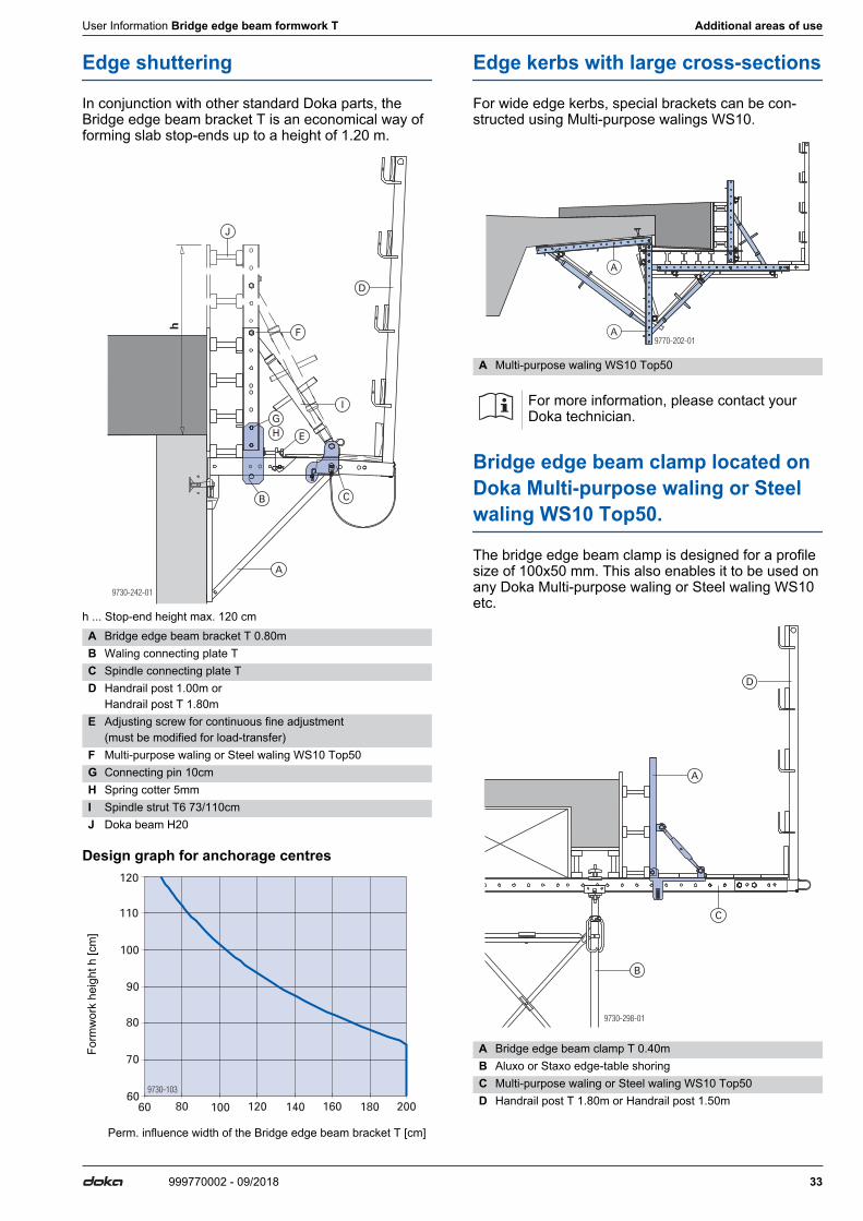
Edge shuttering
In conjunction with other standard Doka parts, the Bridge edge beam bracket T is an economical way of forming slab stop-ends up to a height of 1.20 m.
h ... Stop-end height max. 120 cm
Design graph for anchorage centres
Edge kerbs with large cross-sections
For wide edge kerbs, special brackets can be con-structed using Multi-purpose walings WS10.
Bridge edge beam clamp located on Doka Multi-purpose waling or Steel waling WS10 Top50.
The bridge edge beam clamp is designed for a profile size of 100x50 mm. This also enables it to be used on any Doka Multi-purpose waling or Steel waling WS10 etc.
A Bridge edge beam bracket T 0.80mB Waling connecting plate TC Spindle connecting plate TD Handrail post 1.00m or
Handrail post T 1.80mE Adjusting screw for continuous fine adjustment
(must be modified for load-transfer)F Multi-purpose waling or Steel waling WS10 Top50G Connecting pin 10cmH Spring cotter 5mmI Spindle strut T6 73/110cmJ Doka beam H20
Form
wor
k he
ight
h [c
m]
Perm. influence width of the Bridge edge beam bracket T [cm]
9730-242-01
h
A
B C
D
E
F
GH
I
J
9730-103
120
110
100
90
80
70
6060 80 100 120 140 160 180 200
A Multi-purpose waling WS10 Top50
For more information, please contact your Doka technician.
A Bridge edge beam clamp T 0.40mB Aluxo or Staxo edge-table shoringC Multi-purpose waling or Steel waling WS10 Top50D Handrail post T 1.80m or Handrail post 1.50m
97 -2 -0170 02
A
A
9730-298-01
A
B
C
D
34 999770002 - 09/2018
Additional areas of use User Information Bridge edge beam formwork T
User Information Bridge edge beam formwork T General remarks
35999770002 - 09/2018
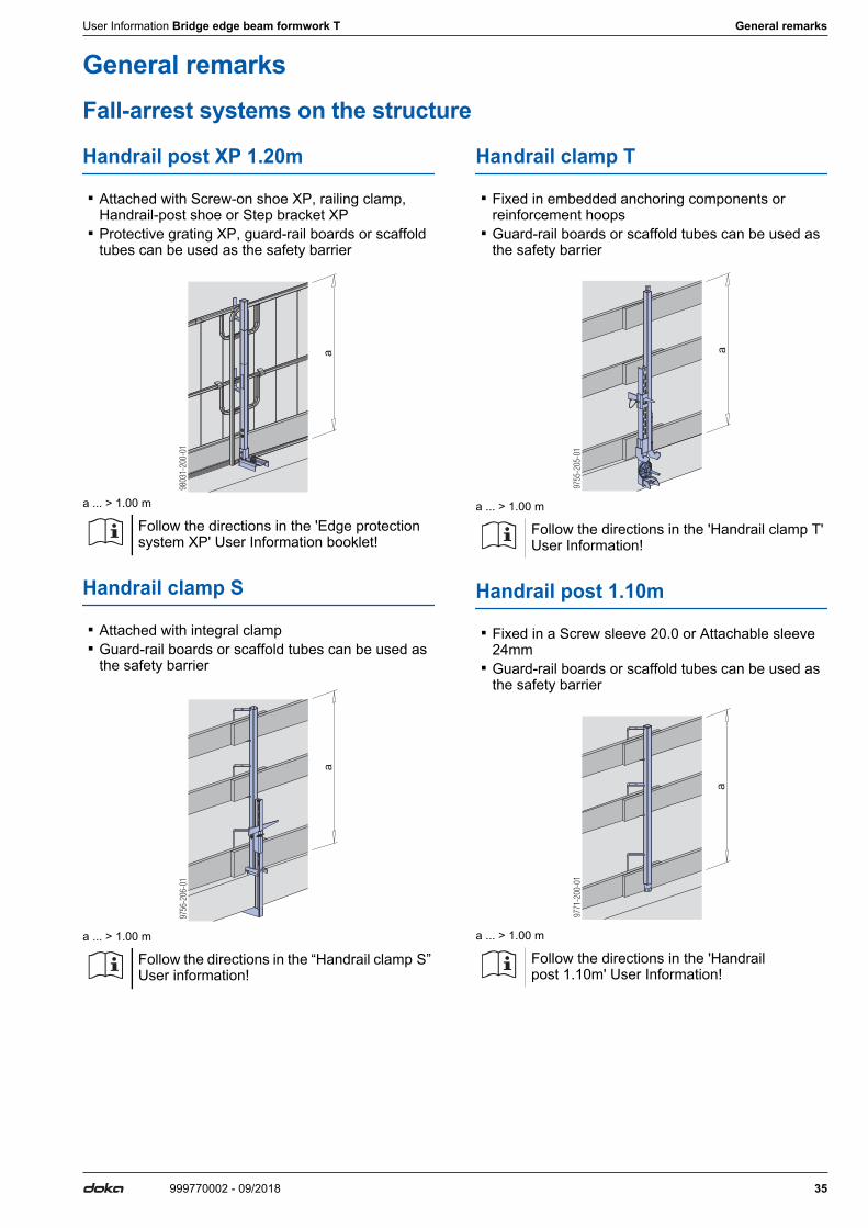
General remarksFall-arrest systems on the structure
Handrail post XP 1.20m
▪ Attached with Screw-on shoe XP, railing clamp, Handrail-post shoe or Step bracket XP
▪ Protective grating XP, guard-rail boards or scaffold tubes can be used as the safety barrier
a ... > 1.00 m
Handrail clamp S
▪ Attached with integral clamp ▪ Guard-rail boards or scaffold tubes can be used as
the safety barrier
a ... > 1.00 m
Handrail clamp T
▪ Fixed in embedded anchoring components or reinforcement hoops
▪ Guard-rail boards or scaffold tubes can be used as the safety barrier
a ... > 1.00 m
Handrail post 1.10m
▪ Fixed in a Screw sleeve 20.0 or Attachable sleeve 24mm
▪ Guard-rail boards or scaffold tubes can be used as the safety barrier
a ... > 1.00 m
Follow the directions in the 'Edge protection system XP' User Information booklet!
Follow the directions in the “Handrail clamp S” User information!
9803
1-20
0-01
aa
9756
-206
-01
Follow the directions in the 'Handrail clamp T' User Information!
Follow the directions in the 'Handrail post 1.10m' User Information!
a
9755
-205
-01
a
9771
-200
-01
36 999770002 - 09/2018
General remarks User Information Bridge edge beam formwork T
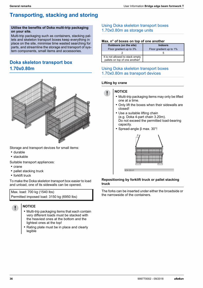
Transporting, stacking and storing
Doka skeleton transport box 1.70x0.80m
Storage and transport devices for small items: ▪ durable ▪ stackableSuitable transport appliances: ▪ crane ▪ pallet stacking truck ▪ forklift truckTo make the Doka skeleton transport box easier to load and unload, one of its sidewalls can be opened.
Using Doka skeleton transport boxes 1.70x0.80m as storage units
Max. n° of boxes on top of one another
Using Doka skeleton transport boxes 1.70x0.80m as transport devices
Lifting by crane
Repositioning by forklift truck or pallet stacking truck
The forks can be inserted under either the broadside or the narrowside of the containers.
Utilise the benefits of Doka multi-trip packaging on your site.Multi-trip packaging such as containers, stacking pal-lets and skeleton transport boxes keep everything in place on the site, minimise time wasted searching for parts, and streamline the storage and transport of sys-tem components, small items and accessories.
Max. load: 700 kg (1540 lbs)Permitted imposed load: 3150 kg (6950 lbs)
NOTICE ▪ Multi-trip packaging items that each contain
very different loads must be stacked with the heaviest ones at the bottom and the lightest ones at the top!
▪ Rating plate must be in place and clearly legible
Outdoors (on the site) IndoorsFloor gradient up to 3% Floor gradient up to 1%
2 5It is not allowed to stack empty pallets on top of one another!
NOTICE ▪ Multi-trip packaging items may only be lifted
one at a time. ▪ Only lift the boxes when their sidewalls are
closed! ▪ Use a suitable lifting chain
(e.g. Doka 4-part chain 3.20m). Do not exceed the permitted load-bearing capacity.
▪ Spread-angle β max. 30°!
9234-203-01
User Information Bridge edge beam formwork T General remarks
37999770002 - 09/2018
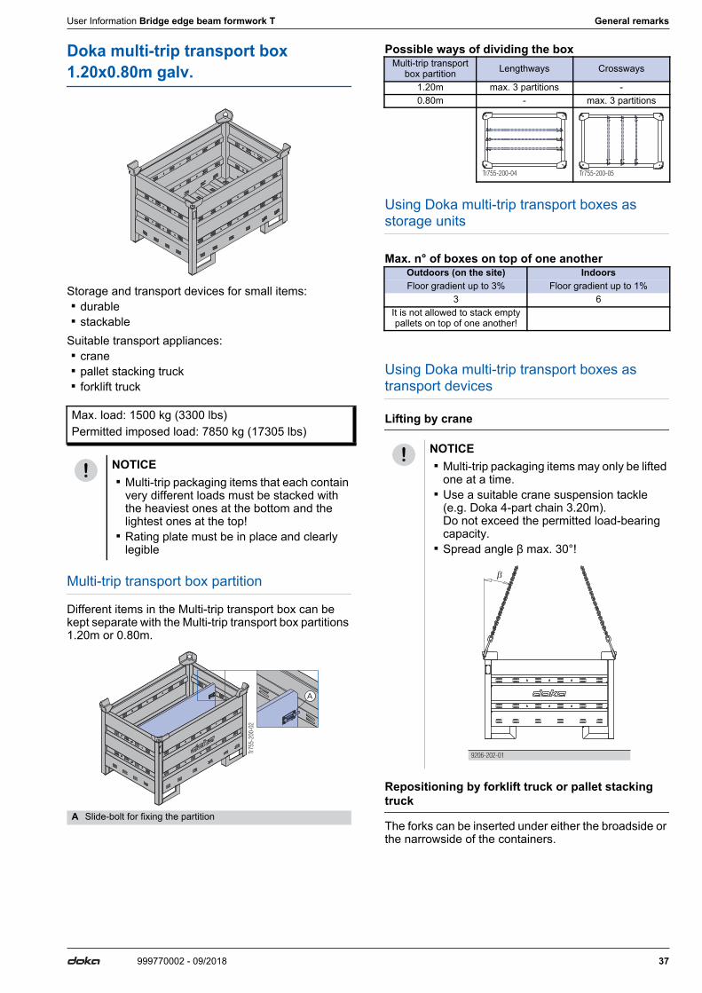
Doka multi-trip transport box 1.20x0.80m galv.
Storage and transport devices for small items: ▪ durable ▪ stackableSuitable transport appliances: ▪ crane ▪ pallet stacking truck ▪ forklift truck
Multi-trip transport box partition
Different items in the Multi-trip transport box can be kept separate with the Multi-trip transport box partitions 1.20m or 0.80m.
Possible ways of dividing the box
Using Doka multi-trip transport boxes as storage units
Max. n° of boxes on top of one another
Using Doka multi-trip transport boxes as transport devices
Lifting by crane
Repositioning by forklift truck or pallet stacking truck
The forks can be inserted under either the broadside or the narrowside of the containers.
Max. load: 1500 kg (3300 lbs)Permitted imposed load: 7850 kg (17305 lbs)
NOTICE ▪ Multi-trip packaging items that each contain
very different loads must be stacked with the heaviest ones at the bottom and the lightest ones at the top!
▪ Rating plate must be in place and clearly legible
A Slide-bolt for fixing the partition
Tr75
5-20
0-02
A
Multi-trip transport box partition Lengthways Crossways
1.20m max. 3 partitions -0.80m - max. 3 partitions
Outdoors (on the site) IndoorsFloor gradient up to 3% Floor gradient up to 1%
3 6It is not allowed to stack empty pallets on top of one another!
NOTICE ▪ Multi-trip packaging items may only be lifted
one at a time. ▪ Use a suitable crane suspension tackle
(e.g. Doka 4-part chain 3.20m). Do not exceed the permitted load-bearing capacity.
▪ Spread angle β max. 30°!
Tr755-200-04 Tr755-200-05
9206-202-01
38 999770002 - 09/2018
General remarks User Information Bridge edge beam formwork T
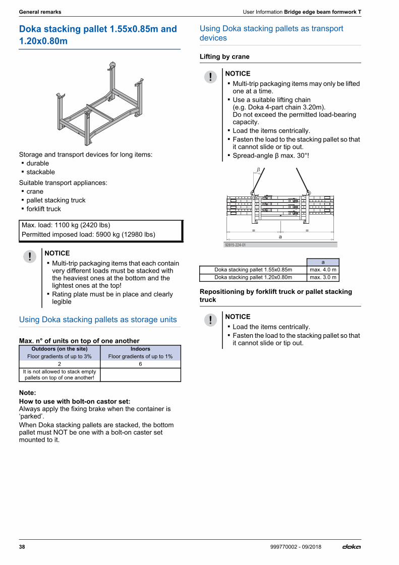
Doka stacking pallet 1.55x0.85m and 1.20x0.80m
Storage and transport devices for long items: ▪ durable ▪ stackableSuitable transport appliances: ▪ crane ▪ pallet stacking truck ▪ forklift truck
Using Doka stacking pallets as storage units
Max. n° of units on top of one another
Note:How to use with bolt-on castor set: Always apply the fixing brake when the container is ‘parked’.When Doka stacking pallets are stacked, the bottom pallet must NOT be one with a bolt-on caster set mounted to it.
Using Doka stacking pallets as transport devices
Lifting by crane
Repositioning by forklift truck or pallet stacking truck
Max. load: 1100 kg (2420 lbs)Permitted imposed load: 5900 kg (12980 lbs)
NOTICE ▪ Multi-trip packaging items that each contain
very different loads must be stacked with the heaviest ones at the bottom and the lightest ones at the top!
▪ Rating plate must be in place and clearly legible
Outdoors (on the site) IndoorsFloor gradients of up to 3% Floor gradients of up to 1%
2 6It is not allowed to stack empty pallets on top of one another!
NOTICE ▪ Multi-trip packaging items may only be lifted
one at a time. ▪ Use a suitable lifting chain
(e.g. Doka 4-part chain 3.20m). Do not exceed the permitted load-bearing capacity.
▪ Load the items centrically. ▪ Fasten the load to the stacking pallet so that
it cannot slide or tip out. ▪ Spread-angle β max. 30°!
aDoka stacking pallet 1.55x0.85m max. 4.0 mDoka stacking pallet 1.20x0.80m max. 3.0 m
NOTICE ▪ Load the items centrically. ▪ Fasten the load to the stacking pallet so that
it cannot slide or tip out.
92815-2 -0124
a
= =
User Information Bridge edge beam formwork T General remarks
39999770002 - 09/2018
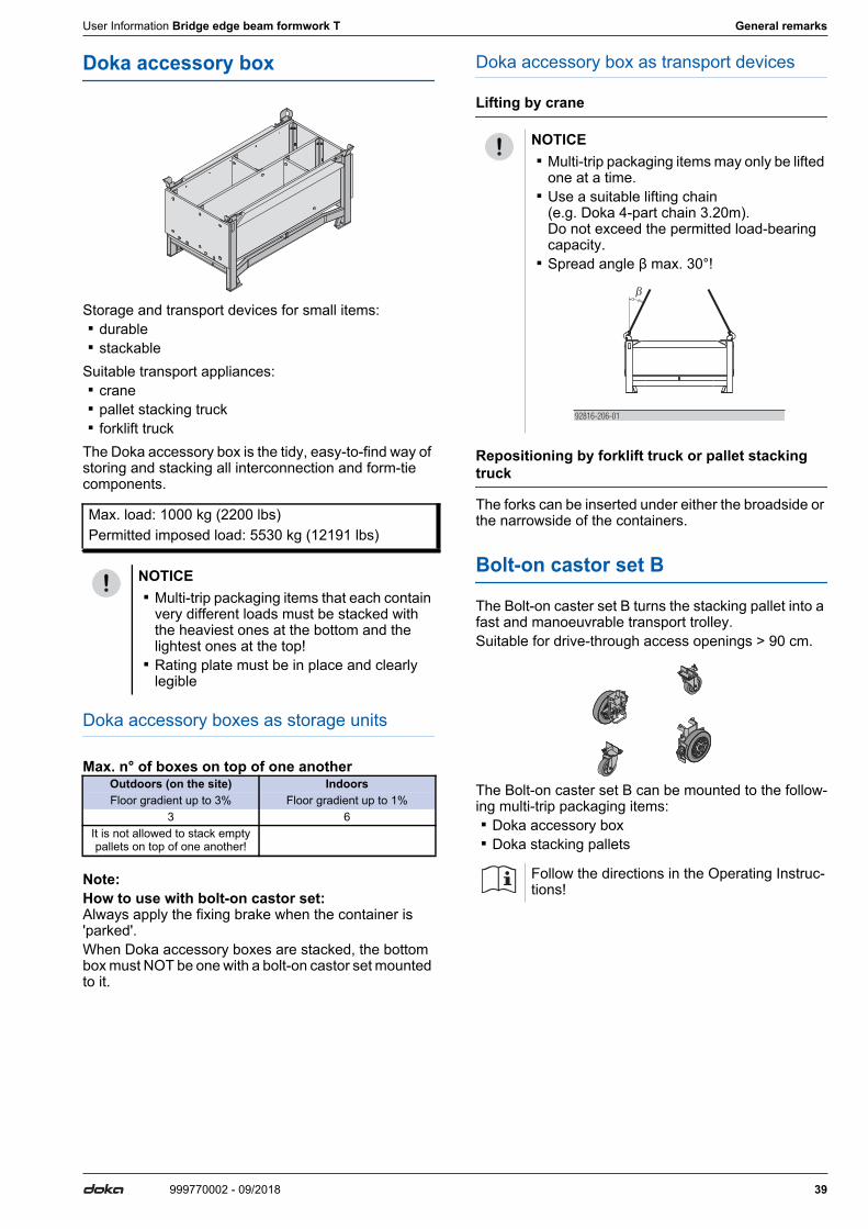
Doka accessory box
Storage and transport devices for small items: ▪ durable ▪ stackableSuitable transport appliances: ▪ crane ▪ pallet stacking truck ▪ forklift truckThe Doka accessory box is the tidy, easy-to-find way of storing and stacking all interconnection and form-tie components.
Doka accessory boxes as storage units
Max. n° of boxes on top of one another
Note:How to use with bolt-on castor set: Always apply the fixing brake when the container is 'parked'.When Doka accessory boxes are stacked, the bottom box must NOT be one with a bolt-on castor set mounted to it.
Doka accessory box as transport devices
Lifting by crane
Repositioning by forklift truck or pallet stacking truck
The forks can be inserted under either the broadside or the narrowside of the containers.
Bolt-on castor set B
The Bolt-on caster set B turns the stacking pallet into a fast and manoeuvrable transport trolley.Suitable for drive-through access openings > 90 cm.
The Bolt-on caster set B can be mounted to the follow-ing multi-trip packaging items: ▪ Doka accessory box ▪ Doka stacking pallets
Max. load: 1000 kg (2200 lbs)Permitted imposed load: 5530 kg (12191 lbs)
NOTICE ▪ Multi-trip packaging items that each contain
very different loads must be stacked with the heaviest ones at the bottom and the lightest ones at the top!
▪ Rating plate must be in place and clearly legible
Outdoors (on the site) IndoorsFloor gradient up to 3% Floor gradient up to 1%
3 6It is not allowed to stack empty pallets on top of one another!
NOTICE ▪ Multi-trip packaging items may only be lifted
one at a time. ▪ Use a suitable lifting chain
(e.g. Doka 4-part chain 3.20m). Do not exceed the permitted load-bearing capacity.
▪ Spread angle β max. 30°!
Follow the directions in the Operating Instruc-tions!
92816-206-01
Article n°[kg] Article n°[kg]
40 999770002 - 09/2018
Component overview User Information Bridge edge beam formwork T
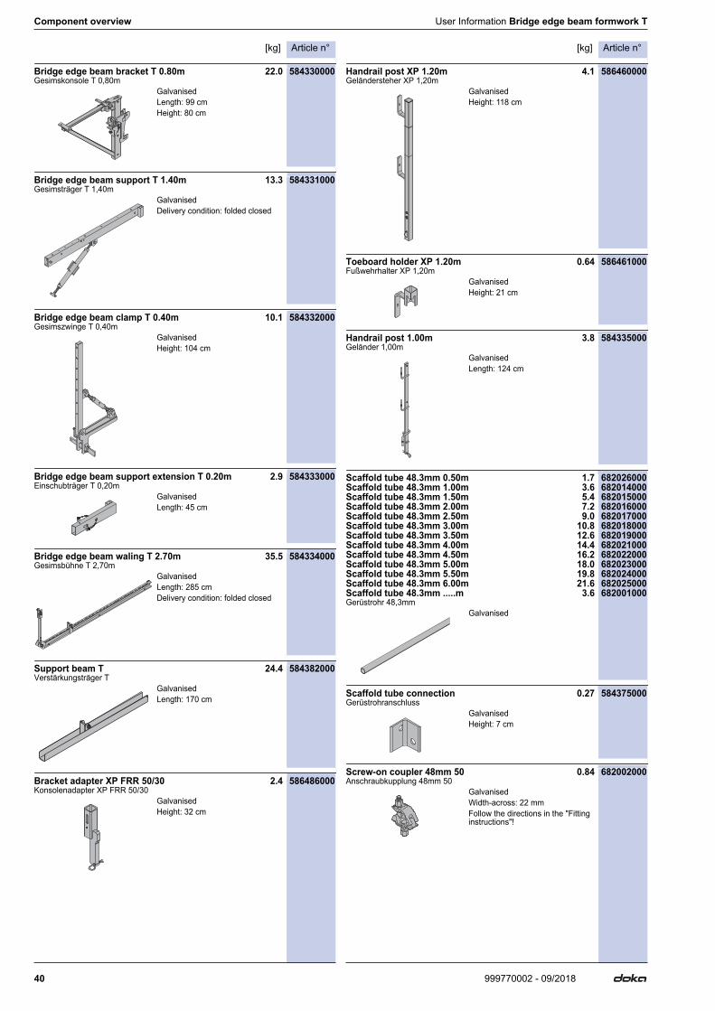
Component overview[kg]Article n°
Bridge edge beam bracket T 0.80m 22.0 584330000Gesimskonsole T 0,80m
Bridge edge beam support T 1.40m 13.3 584331000Gesimsträger T 1,40m
Bridge edge beam clamp T 0.40m 10.1 584332000Gesimszwinge T 0,40m
Bridge edge beam support extension T 0.20m 2.9 584333000Einschubträger T 0,20m
Bridge edge beam waling T 2.70m 35.5 584334000Gesimsbühne T 2,70m
Support beam T 24.4 584382000Verstärkungsträger T
Bracket adapter XP FRR 50/30 2.4 586486000Konsolenadapter XP FRR 50/30
Handrail post XP 1.20m 4.1 586460000Geländersteher XP 1,20m
Toeboard holder XP 1.20m 0.64 586461000Fußwehrhalter XP 1,20m
Handrail post 1.00m 3.8 584335000Geländer 1,00m
Scaffold tube 48.3mm 0.50m 1.7 682026000Scaffold tube 48.3mm 1.00m 3.6 682014000Scaffold tube 48.3mm 1.50m 5.4 682015000Scaffold tube 48.3mm 2.00m 7.2 682016000Scaffold tube 48.3mm 2.50m 9.0 682017000Scaffold tube 48.3mm 3.00m 10.8 682018000Scaffold tube 48.3mm 3.50m 12.6 682019000Scaffold tube 48.3mm 4.00m 14.4 682021000Scaffold tube 48.3mm 4.50m 16.2 682022000Scaffold tube 48.3mm 5.00m 18.0 682023000Scaffold tube 48.3mm 5.50m 19.8 682024000Scaffold tube 48.3mm 6.00m 21.6 682025000Scaffold tube 48.3mm .....m 3.6 682001000Gerüstrohr 48,3mm
Scaffold tube connection 0.27 584375000Gerüstrohranschluss
Screw-on coupler 48mm 50 0.84 682002000Anschraubkupplung 48mm 50
GalvanisedLength: 99 cmHeight: 80 cm
GalvanisedDelivery condition: folded closed
GalvanisedHeight: 104 cm
GalvanisedLength: 45 cm
GalvanisedLength: 285 cmDelivery condition: folded closed
GalvanisedLength: 170 cm
GalvanisedHeight: 32 cm
GalvanisedHeight: 118 cm
GalvanisedHeight: 21 cm
GalvanisedLength: 124 cm
Galvanised
GalvanisedHeight: 7 cm
GalvanisedWidth-across: 22 mmFollow the directions in the "Fitting instructions"!
Article n°[kg] Article n°[kg]
41999770002 - 09/2018
User Information Bridge edge beam formwork T Component overview
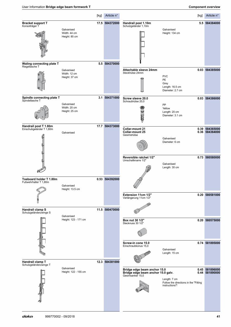
Bracket support T 17.5 584372000Konsolträger T
Waling connecting plate T 5.5 584370000Riegellasche T
Spindle connecting plate T 3.1 584371000Spindellasche T
Handrail post T 1.80m 17.7 584373000Einschubgeländer T 1,80m
Toeboard holder T 1.80m 0.53 584392000Fußwehrhalter T 1,80m
Handrail clamp S 11.5 580470000Schutzgeländerzwinge S
Handrail clamp T 12.3 584381000Schutzgeländerzwinge T
Handrail post 1.10m 5.5 584384000Schutzgeländer 1,10m
Attachable sleeve 24mm 0.03 584385000Steckhülse 24mm
Screw sleeve 20.0 0.03 584386000Schraubhülse 20,0
Collar-mount 21 0.39 584365000Collar-mount 25 0.36 584364000Gesimshülse
Reversible ratchet 1/2" 0.73 580580000Umschaltknarre 1/2"
Extension 11cm 1/2" 0.20 580581000Verlängerung 11cm 1/2"
Box nut 30 1/2" 0.20 580575000Stecknuss 30 1/2"
Screw-in cone 15.0 0.74 581895000Einschraubkonus 15,0
Bridge edge beam anchor 15.0 0.45 581896000Bridge edge beam anchor 15.0 galv. 0.44 581890000Gesimsanker 15,0
GalvanisedWidth: 44 cmHeight: 85 cm
GalvanisedWidth: 12 cmHeight: 37 cm
GalvanisedWidth: 20 cmHeight: 25 cm
Galvanised
GalvanisedHeight: 13.5 cm
GalvanisedHeight: 123 - 171 cm
GalvanisedHeight: 122 - 155 cm
GalvanisedHeight: 134 cm
PVCPEGreyLength: 16.5 cmDiameter: 2.7 cm
PPYellowLength: 20 cmDiameter: 3.1 cm
GalvanisedDiameter: 6 cm
GalvanisedLength: 30 cm
GalvanisedLength: 15 cm
Length: 7 cmFollow the directions in the "Fitting instructions"!
Article n°[kg] Article n°[kg]
42 999770002 - 09/2018
Component overview User Information Bridge edge beam formwork T
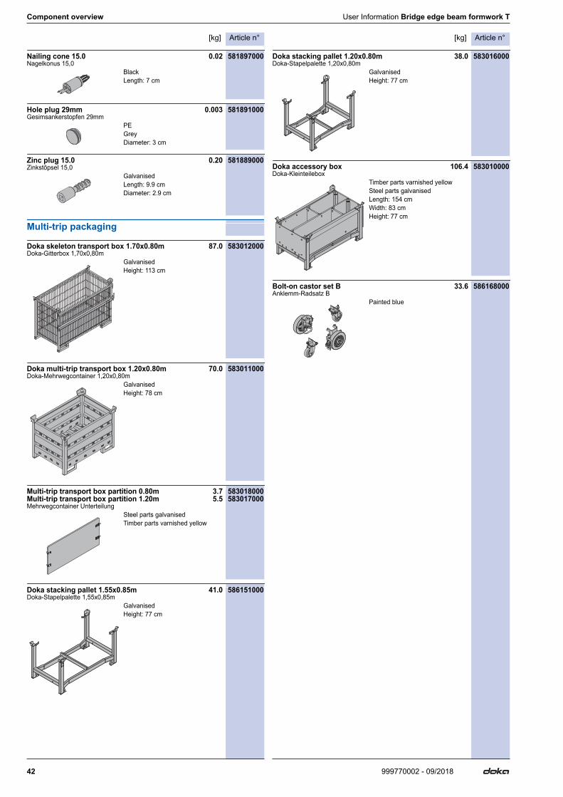
Nailing cone 15.0 0.02 581897000Nagelkonus 15,0
Hole plug 29mm 0.003 581891000Gesimsankerstopfen 29mm
Zinc plug 15.0 0.20 581889000Zinkstöpsel 15,0
Multi-trip packaging
Doka skeleton transport box 1.70x0.80m 87.0 583012000Doka-Gitterbox 1,70x0,80m
Doka multi-trip transport box 1.20x0.80m 70.0 583011000Doka-Mehrwegcontainer 1,20x0,80m
Multi-trip transport box partition 0.80m 3.7 583018000Multi-trip transport box partition 1.20m 5.5 583017000Mehrwegcontainer Unterteilung
Doka stacking pallet 1.55x0.85m 41.0 586151000Doka-Stapelpalette 1,55x0,85m
Doka stacking pallet 1.20x0.80m 38.0 583016000Doka-Stapelpalette 1,20x0,80m
Doka accessory box 106.4 583010000Doka-Kleinteilebox
Bolt-on castor set B 33.6 586168000Anklemm-Radsatz B
BlackLength: 7 cm
PEGreyDiameter: 3 cm
GalvanisedLength: 9.9 cmDiameter: 2.9 cm
GalvanisedHeight: 113 cm
GalvanisedHeight: 78 cm
Steel parts galvanisedTimber parts varnished yellow
GalvanisedHeight: 77 cm
GalvanisedHeight: 77 cm
Timber parts varnished yellowSteel parts galvanisedLength: 154 cmWidth: 83 cmHeight: 77 cm
Painted blue

User Information Bridge edge beam formwork T Component overview
43999770002 - 09/2018

999770002 - 09/2018Doka GmbH | Josef Umdasch Platz 1 | 3300 Amstetten | Austria | T +43 7472 605-0 | F +43 7472 66430 | [email protected] | www.doka.com
Near to you, worldwide
Doka is one of the world leaders in developing, manu-facturing and distributing formwork technology for use in all fields of the construction sector.With more than 160 sales and logistics facilities in over 70 countries, the Doka Group has a highly efficient dis-tribution network which ensures that equipment and
technical support are provided swiftly and profession-ally.An enterprise forming part of the Umdasch Group, the Doka Group employs a worldwide workforce of more than 6000.
www.doka.com/bridge-edge-beam-formwork-T


![Framed formwork Framax Xlife - Doka · [kg] Article n° [kg] Article n° Doka Wall SystemsFramed formwork Framax Xlife Framax Xlife panel 1.35x2.70m 210.0 588100500 Framax Xlife …](https://img.pdfslide.us/doc/110x75/5acb9dc97f8b9a93268b6e8f/framed-formwork-framax-xlife-doka-kg-article-n-kg-article-n-doka-wall-systemsframed.jpg)


![Framed formwork Frami Xlife - Doka · [kg] Article n° [kg] Article n° Doka Wall SystemsFramed formwork Frami Xlife Frami Xlife panel 0.30x1.20m 19.5 588405500 Frami Xlife panel](https://img.pdfslide.us/doc/110x75/5af674c87f8b9a4d4d907a74/framed-formwork-frami-xlife-doka-kg-article-n-kg-article-n-doka-wall-systemsframed.jpg)