Embed Size (px)
Citation preview
BRAZING COPPER TO DISPERSION-STRENGTHENED COPPER
David G. Ryding, Douglas Allen, Advanced Photon Source ECEIVED Richard Lee, Energy Technology AOG 1 2 836
Argonne National Laboratory 9700 S. Cass Avenue
Argonne, Illinois 60439
ABSTRACT
The wbmitted manuscript has been authored by a contractor of the U. S. Government under contrwt No. W-31-104ENG-38. Accordingly, the U. S Government retains a nonexclusive. royalty-free license to publish or reproduce the published form of this contribution, or allow others to do so, for
The Advanced Photon Source (APS) is a state-of-the-art synchrotron light source that will produce intense x-ray beams, which will allow the study of smaller samples and faster reactions and processes at a greater level of detail than has been possible to date. The beam is produced by using third-generation insertion devices in a 7-GeV (7 billion electron volts) electron/positron storage ring that is 1,104 meters (2/3 mile) in circumference. The heat load from these intense high-power devices is very high, and certain components must sustain total heat loads of 3 to 15 kW and heat fluxes of 30 W/mm2. Because the beams will cycle on and off many times, thermal shock and fatigue will be a problem. High heat flux impinging on a small area causes a large thermal gradient that results in high stress. GlidCop@, a dispersion- strengthened copper, is the desired design material because of its high thermal conductivity and superior mechanical properties as compared to copper and its alloys. GlidCop is not amenable to joining by fusion welding, and brazing requires diligence because of high diffusivity. Brazing procedures were developed using optical and scanning electron microscopy.
INTRODUCTION
The Advanced Photon Source (APS) front ends (FEs) are systems that condition the intense photon beam generated by the APS and incorporate the safety features necessary to handle the high-power photon beams. The FEs must be especially robust to allow continuous operation for 24 hours a day, every day, for the life of the synchrotron. More than 1,000 scientists from around the world are expected to use the APS facility every year; they must schedule experiments far in advance and then perform the work during the period specified.
Design constraints on the FEs are cooling mode and coolant; ultrahigh vacuum (UHV); x- ray, gamma ray, and neutron radiation resistance; and equipment protection and personnel safety concerns (EPS and PSS). The APS front-end coolant is deionized water.
The photon shutters and fixed masks are the components exposed to the highest heat load. The shutters are needed to stop the beam and are fabricated from high-purity, high- conductivity, oxygen-free copper (OFHC) with a GlidCop plate brazed or explosion-bonded to

DISCLAIMER
This report was prepared as an account of work sponsored by an agency of the United States Government. Neither the United States Government nor any agency thereof, nor any of their employees, makes any warranty, express or implied, or assumes any legal liability or responsibility for the accuracy, completeness, or use- fulness of any information, apparatus, product, or process disclosed, or represents that its use would not infringe privately owned rights. Reference herein to any spe- cific commercial product, process, or service by trade name, trademark, manufac- turer, or otherwise does not necessarily constitute or imply its endorsement, recorn- mendation, or favoring by the United States Government or any agency thereof. The views and opinions of authors expressed herein do not necessarily state or reflect those of the United States Government or any agency thereof.

DISCLAIMER
Portions of this document may be illegible in electronic image products. Images are produced from the best available original document.
.
i t . The fixed masks collimate the beam and protect downstream components and beamline piping from misaligned high-energy beams that might otherwise impinge on these surfaces [1,2]. The fixed masks are all GlidCop. A photon shutter prototype has been laser tested at a power density of more than 70 watts/mm2 for 7,000 cycles without failure of the GlidCop braze joint [ 61.
GlidCop is often used in applications in which the component manufacturing process uses high temperatures, such as brazing and glass-to-metal sealing. GlidCop is a dispersion- strengthened OFHC copper made by powder metallurgy techniques. GlidCop AL- 15 is 99.7 weight percent copper (99.3% by volume) and 0.3% weight aluminum oxide (0.7% by volume). GlidCop annealed for 1 hour at 600°C has a yield strength of 400 MPa (58 KSI). The yield strength of copper-zirconium annealed at 600°C is 100 MPa (15 KSI), and OFHC copper is less than 50 MPa (7 KSI) [3,4].
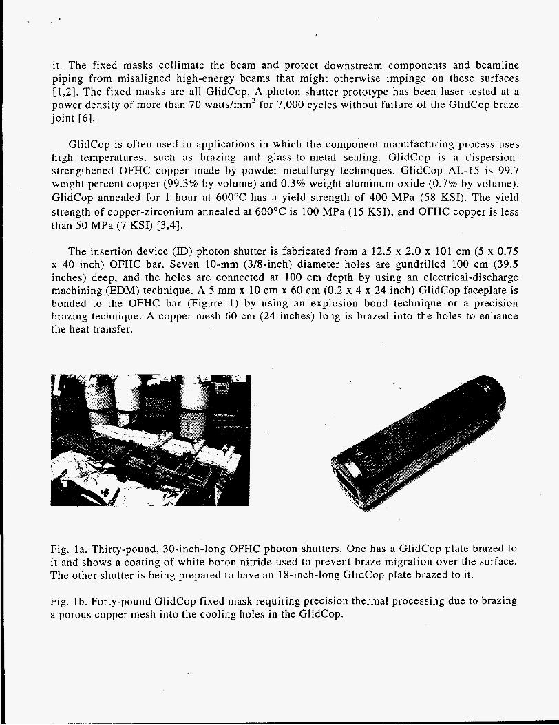
The insertion device (ID) photon shutter is fabricated from a 12.5 x 2.0 x 101 cm (5 x 0.75 x 40 inch) OFHC bar. Seven 10-mm (3Winch) diameter holes are gundrilled 100 cm (39.5 inches) deep, and the holes are connected at 100 cm depth by using an electrical-discharge machining (EDM) technique. A 5 mm x 10 cm x 60 cm (0.2 x 4 x 24 inch) GlidCop faceplate is bonded to the OFHC bar (Figure 1) by using an explosion bond technique or a precision brazing technique. A copper mesh 60 cm (24 inches) long is brazed into the holes to enhance the heat transfer.
Fig. la. Thirty-pound, 30-inch-long OFHC photon shutters. One has a GlidCop plate brazed to i t and shows a coating of white boron nitride used to prevent braze migration over the surface. The other shutter is being prepared to have an 18-inch-long GlidCop plate brazed to it.
Fig. 1 b. Forty-pound GlidCop fixed mask requiring precision thermal processing due to brazing a porous copper mesh into the cooling holes in the GlidCop.
MATERIALS
Conventional high-heat-flux materials, such as tantalum, tungsten, and molybdenum, do not transfer heat as effectively as do OFHC and GlidCop and are used for other, lower-power APS components that require high strength or greater x-ray stopping power. Pyrolitic graphite, diamond-like carbon, and silicon carbide show promise but have limited availability and limited data concerning synchrotron usage and design criteria. Beryllium has good heat transfer and mechanical properties but has serious environmental, safety, and health (ESH) concerns.
Work-hardened copper and copper alloys are mechanically stronger than OFHC but lose their strength during a high-temperature braze cycle. Alloyed copper has less than half the thermal conductivity of OFHC [ 5 ] .
GlidCop has 90% the thermal conductivity of OFHC, retains its strength after high- temperature brazing, and has tensile strengths ranging from 380 to 700 MPa. GlidCop comprises a pure copper matrix strengthened by a uniform dispersion of 3 to 12 nm size A1203 dispersoids that are stable up to the melting point and prevent recrystallization and softening; therefore, the electrical and thermal conductivities remain unaffected by high temperatures.
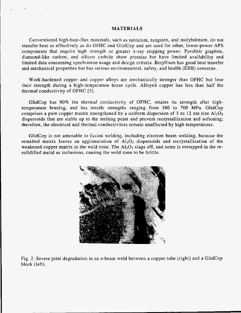
GlidCop is not amenable to fusion welding, including electron beam welding, because the remelted matrix leaves an agglomeration of A1203 dispersoids and recrystallization of the weakened copper matrix in the weld zone. The A1203 slags off, and some is entrapped in the re- solidified metal as inclusions, causing the weld zone to be brittle.
Fig. 2. Severe joint degradation in an e-beam weld between a copper tube (right) and a GlidCop block (left).
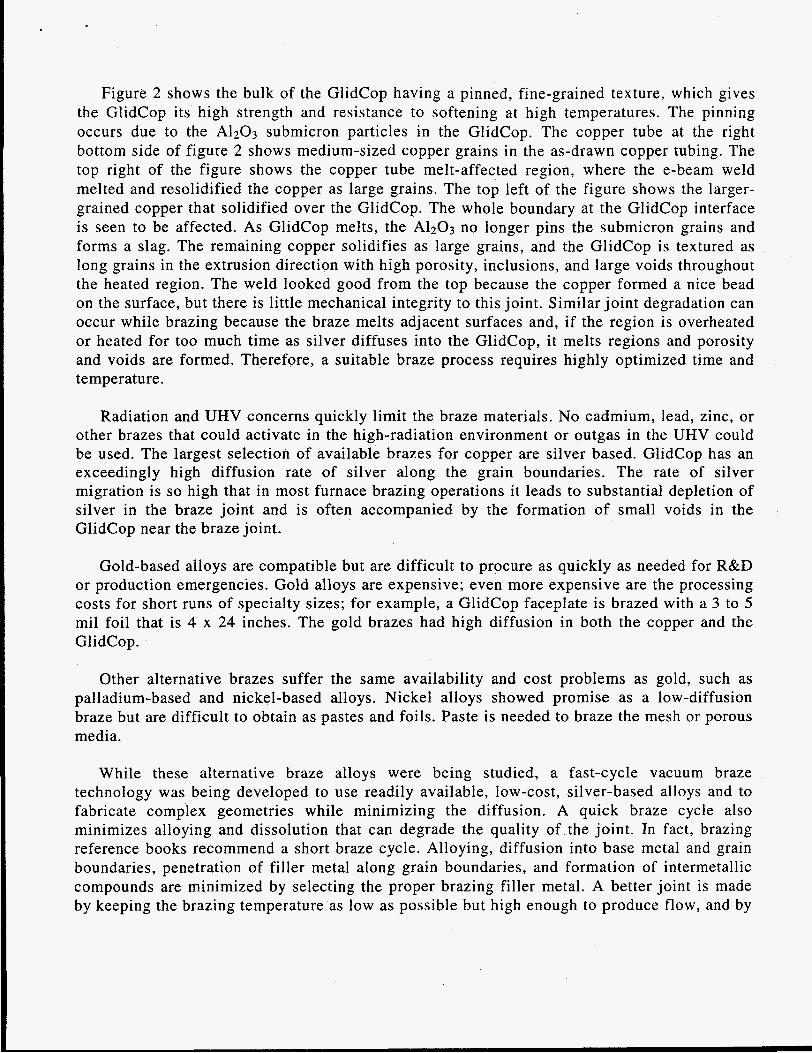
Figure 2 shows the bulk of the GlidCop having a pinned, fine-grained texture, which gives the GlidCop its high strength and resistance to softening at high temperatures. The pinning occurs due to the A1203 submicron particles in the GlidCop. The copper tube at the right bottom side of figure 2 shows medium-sized copper grains in the as-drawn copper tubing. The top right of the figure shows the copper tube melt-affected region, where the e-beam weld melted and resolidified the copper as large grains. The top left of the figure shows the larger- grained copper that solidified over the GlidCop. The whole boundary at the GlidCop interface is seen to be affected. As GlidCop melts, the A1203 no longer pins the submicron grains and forms a slag. The remaining copper solidifies as large grains, and the GlidCop is textured as long grains in the extrusion direction with high porosity, inclusions, and large voids throughout the heated region. The weld looked good from the top because the copper formed a nice bead on the surface, but there is little mechanical integrity to this joint. Similar joint degradation can occur while brazing because the braze melts adjacent surfaces and, if the region is overheated or heated for too much time as silver diffuses into the GlidCop, it melts regions and porosity and voids are formed. Therefore, a suitable braze process requires highly optimized time and temperature.
Radiation and UHV concerns quickly limit the braze materials. No cadmium, lead, zinc, or other brazes that could activate in the high-radiation environment or outgas in the UHV could be used. The largest selection of available brazes for copper are silver based. GlidCop has an exceedingly high diffusion rate of silver along the grain boundaries. The rate of silver migration is so high that in most furnace brazing operations it leads to substantial depletion of silver in the braze joint and is often accompanied by the formation of small voids in the GlidCop near the braze joint.
Gold-based alloys are compatible but are difficult to procure as quickly as needed for R&D or production emergencies. Gold alloys are expensive; even more expensive are the processing costs for short runs of specialty sizes; for example, a GlidCop faceplate is brazed with a 3 to 5 mil foil that is 4 x 24 inches. The gold brazes had high diffusion in both the copper and the GlidCop.
Other alternative brazes suffer the same availability and cost problems as gold, such as palladium-based and nickel-based alloys. Nickel alloys showed promise as a low-diffusion braze but are difficult to obtain as pastes and foils. Paste is needed to braze the mesh or porous media.
While these alternative braze alloys were being studied, a fast-cycle vacuum braze technology was being developed to use readily available, low-cost, silver-based alloys and to fabricate complex geometries while minimizing the diffusion. A quick braze cycle also minimizes alloying and dissolution that can degrade the quality of the joint. In fact, brazing reference books recommend a short braze cycle. Alloying, diffusion into base metal and grain boundaries, penetration of filler metal along grain boundaries, and formation of intermetallic compounds are minimized by selecting the proper brazing filler metal. A better joint is made by keeping the brazing temperature as low as possible but high enough to produce flow, and by
keeping the time at brazing temperature short and cooling the brazed joint as quickly as possible without causing cracking or distortion.
A clean, oxide-free surface is imperative to brazing. The filler metals and base metals must be clean. The time from cleaning and chemical oxide removal is important because of oxidation in air. Because APS components operate in UHV, no flux can be used. To ensure quick heating, the braze furnace was designed to be preheated and the vacuum vessel containing the component is inserted into the hot furnace. Uniformly heating 40-inch-long parts is difficult. A three-zone furnace is used, and thermocouples are positioned in at least six locations: one at each corner and two at each side in the center of the component or braze area of interest. Temperatures are maintained to within 10°C across the component during the critical period of the braze cycle and are typically maintained to within 2°C. The critical period is from when the braze melts until it solidifies and is reduced in temperature to stop diffusion. Quick cooling is performed by removing the hot vacuum chamber from the furnace. Radiative and convective cooling are naturally fast in this mode, and external fans speed up the convective cooling. Accelerated cooling is achieved by cooling the interior with an inert gas flow.
The internal gas quench study was performed by using nitrogen, argon, and helium gas at room temperature and at -150°C after passing the gas through a cooling coil immersed in liquid nitrogen. Helium cools several times faster than nitrogen or argon.
The key to developing and confidently using a quick heating process is data acquisition. A cost-effective, computer-based data acquisition system is used, and dozens of thermocouples can be simultaneously recorded and displayed. The data are reduced and extensively analyzed after the braze cycle by using a spreadsheet program. Calibration loads, which can be the component without braze, are instrumented and processed and, after data analysis, the process is iterated and the cycle is repeated until the speed and temperature profiles are acceptable.
The cycle time from when the braze first melts to when it solidifies can be shorter than one minute. For copper to copper brazing, 20 minutes at 50°C over the melt temperature does not significantly affect the joint. This time represents a practical trade-off between speed and manufacturing. Faster processing is difficult.
COPPER TO DISPERSION-STRENGTHENED COPPER BRAZING
Copper to GlidCop brazing has other aspects. The above references have indicated an industry awareness of the problems associated with silver brazing GlidCop [3]. APS GlidCop components are adversely affected if the temperatures are more than 20°C above the melt temperature and if the melt cycle time is more than a few minutes. Again, the process can be made faster, but it is not necessary. For example, to cool the 40-pound copper component quickly, as many as four cylinders of helium gas cooled to -150°C have been used. One quarter of a cylinder is used in a less aggressive brazing process.
Optimizing a braze process to minimize diffusion and achieve a high-quality joint required an analytical technique that could determine the elemental composition of a joint and the adjacent regions after a braze process. Scanning electron microscope (SEM) elemental distribution maps that use x-ray energy dispersive spectroscopy (EDS) are ideal for developing a brazing process that has a complex elemental redistribution after brazing.
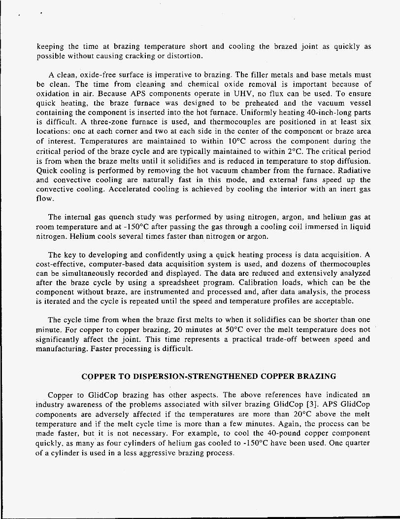
Phase mapping basically takes the individual x-ray elemental maps and combines them with a minimum threshold level to display a new image. The new image shows where elements are combined to form a phase. For example, in Figure 3, the phase map indicates where silver and copper are found together, indicating alloying, and the relative percent of total image area. The new image is a set of binary images, which are assigned a color intensity when displayed. When the maps are acquired, it is possible for counts of more than one element to be stored in the individual pixels of the digital image, indicating the presence (but not the exact composition) of compounds.
Fig. 3. Scanning electron micrograph x-ray map of a GlidCop (top) to copper (bottom) optimized braze joint using a 60%Ag30%CulO%Sn braze alloy foil 0.003 inches thick. There is little silver diffusion into the copper at the bottom, and more than a foil thickness diffuses into the GlidCop. The time in the liquid state was less than one minute. No voids or porosity are observed.
Quantitative analysis of interfaces is performed by spot analysis in the EDS system under similar conditions as mapping. The points are spaced in increments across the interface, and the composition is calculated by using a ZAF (atomic number, absorption, fluorescence) correction program. Compounds formed in the braze material or interfaces are also examined by EDS spot analysis in the SEM.

BRAZING FABRICATION DIFFICULTIES OF GLIDCOP TO COPPER
Brazing GlidCop to copper with silver brazes requires precise temperature control. The braze samples were heated more than 50°C above liquidus, which is a typical commercial braze process, and determined that this process is unacceptable because of the high silver diffusion into the GlidCop. Tests that were only 10°C above liquidus but held the temperature for 10 minutes had unacceptable results. The fixed masks incorporate porous media in the water cooling channels to enhance the heat transfer. The porous media are copper-mesh-brazed into GlidCop. Because of the small amount of contact area between the mesh and the cooling channel, little braze is available in these regions. Too much heat or too long of a time at liquid temperatures allows too much silver to diffuse away from the joint, leaving a nonbond or a weak bond in that area. The above tests were performed by using copper mesh in a GlidCop tube. The mesh was not bonded and was easily removed.
When a precision fast thermal cycle is employed, the copper mesh is firmly bonded to the GlidCop and survives rigorous mechanical punishment. The stainless steel center rod was pounded out of a mesh without the mesh releasing from the GlidCop.
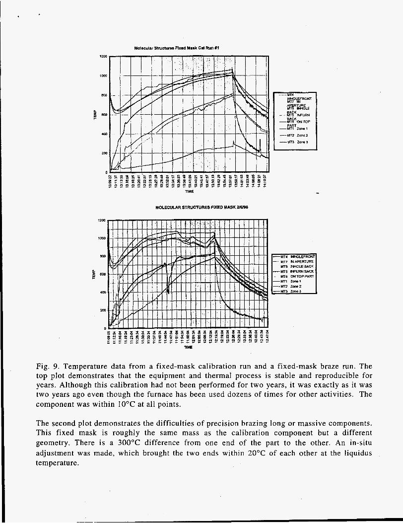
Figure 9 demonstrates the silver braze fabrication difficulties encountered when brazing long or massive GlidCop components. This calibration plot was recently run by using our standard insertion device (ID) first fixed-mask design from three years ago. The higher- temperature data are the furnace temperatures. The lower-temperature data are the 40-pound GlidCop mask showing temperatures at the two ends of the component. The temperatures are within 10°C of each other, even though this test had not been run for two years, which demonstrates that the process is reproducible and appropriate for manufacturing.
The second plot demonstrates the difficulties of precision brazing long or massive components. This fixed mask is a slightly different design but roughly the same mass. It was placed in exactly the same position as the calibration run shown above. There is as much as a 300°C difference from one end to the other! An in-situ adjustment was made, which is seen as the blip in the center of the plot, and the ends were brought to within 20°C of each other at the end of the braze cycle. A 50°C difference from one end of the part to the other is unacceptable because the part would have to be heated enough to ensure brazing the cold end, which would make the hot end more than 50°C over the liquidus; this would result in a failed or suspect component.
RESULTS
SILVER, COPPER, TIN
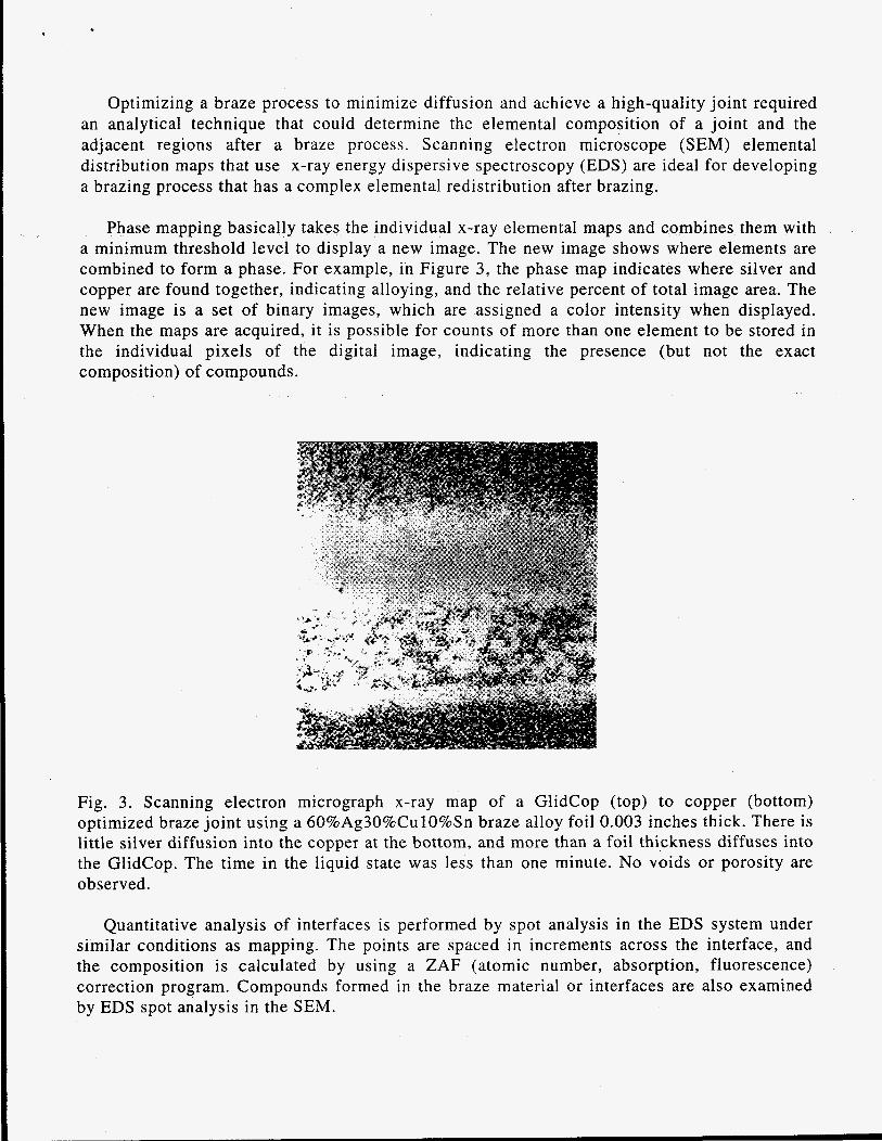
Fig. 4. Silver (Ag) x-ray map showing the silver diffusion into the GlidCop at the top and copper at the bottom. The original braze foil is 0.003 inches.
Fig. 5. SEM x-ray map of tin (Sn) showing that the tin diffusion into GlidCop is at least as high as the silver. A 60%Ag30%CulO%Sn braze alloy foil 0.003 inches thick was used . The tin alloy was tried because tin was suggested to be not as fast a diffuser as silver in copper, and the braze alloy can be used at 100°C lower than the standard 72%Ag28%Cu eutectic braze. The lower temperature did not reduce the diffusion into the GlidCop.
. .
. . ' . . .
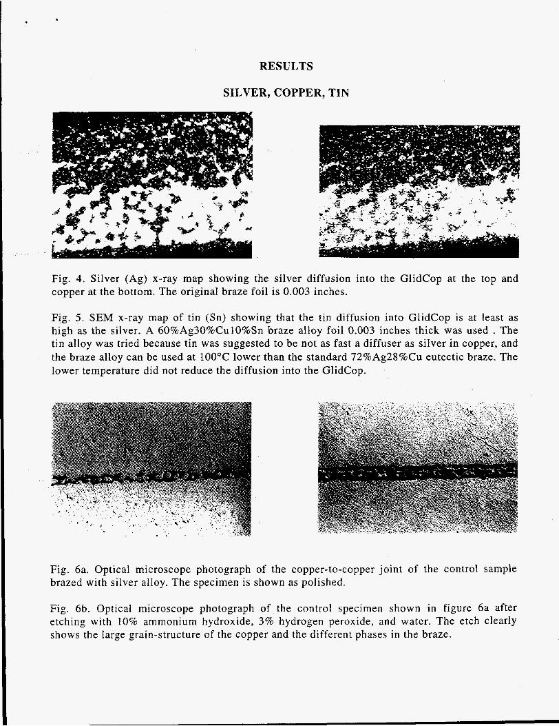
Fig. 6a. Optical microscope photograph of the copper-to-copper joint of the control sample brazed with silver alloy. The specimen is shown as polished.
Fig. 6b. Optical microscope photograph of the control specimen shown i n figure 6a after etching with 10% ammonium hydroxide, 3% hydrogen peroxide, and water. The etch clearly shows the large grain-structure of the copper and the different phases in the braze.

Fig. 7a. A polished sample of GlidCop (top) to copper (bottom) brazed with silver alloy.
Fig. 7b. The 10% ammonium hydroxide etch dramatically enhances the brazed region showing the silver diffusion into the GlidCop (top). The braze joint shows a large-grain structure, and the GlidCop shows the elongated grains. No porosity or voids are observed.
Fig. 8. An SEM photograph of a commercial gold/copper braze of GlidCop and copper, which is a poor joint. The gold/copper braze was studied because of previous reports of it being a suitable braze for GlidCop to copper. There is high diffusion of gold into both the GlidCop and the copper. I
Molecular Structures Fixad Mask C d Run X I
12w
800
4m
200
n
- - -MT4
me MOLE
---.MT5 INFURN
-%%“w TOP
-MT1 Zone1
---MTz Zone2
--MT3 Zone 3
MOLECUW STRUCKIRES FIXED MASK 216198
Fig. 9. Temperature data from a fixed-mask calibration run and a fixed-mask braze run. The top plot demonstrates that the equipment and thermal process is stable and reproducible for years. Although this calibration had not been performed for two years, it was exactly as it was two years ago even though the furnace has been used dozens of times for other activities. The component was within 10°C at all points.
The second plot demonstrates the difficulties of precision brazing long or massive components. This fixed mask is roughly the same mass as the calibration component but a different geometry. There is a 300°C difference from one end of the part to the other. An in-situ adjustment was made, which brought the two ends within 20°C of each other at the liquidus temperature.
CONCLUSION
High silver brazes are better than gold for brazing GlidCop to copper. Expertise in brazing GlidCop with silver-based alloys has been beneficial in many ways. Stainless steel can be brazed to GlidCop by using a thermal process similar to that of brazing mesh or porous media into GlidCop. The advantage of this is that in a single braze process, copper mesh and stainless steel vacuum flanges can be brazed to GlidCop.
A more important benefit has been that many GlidCop component fabrication problems, such as water or vacuum leaks can be repaired. Fluxless tungsten inert gas (TIG) and e-beam brazing techniques have been successfully employed to repair costly GlidCop components. The fluxless TIG and e-beam braze techniques were developed by using the same methodology as that for vacuum brazing GlidCop. Test samples were metallurgically examined by using optical and scanning electron microscopy to determine the diffusion parameters and the integrity of joined regions, and brazing parameters were adjusted according to the metallurgical feedback. The TIG braze techniques have also been used to repair OFHC copper components. The TIG technique has been employed on very large copper components in-situ in the 2/3 mile APS synchrotron tunnel. The e-beam braze technique has been used to fabricate beamline components and large x-ray mirror copper components.
A photon shutter prototype has been laser tested at a power density of more than 70 watts/mm2 for 7,000 cycles without failure of the GlidCop braze joint [ 6 ] .
REFERENCES
1. D. Shu, J . Barraza, T. Sanchez, R.W. Neilsen, J.T. Collins, and T.M. Kuzay, Front End Designs for the 7 GeV Advanced Photon Source, Advanced Photon Source, Nuclear Instruments and Methods in Physics Research A319 63-70 (1992).
2. D. Shu, T. Nian, 2. Wang, J.T. Collins, D.G. Ryding, and T.M. Kuzay, The First Photon Shutter Development for APS Insertion Device Beamline Front Ends, SPIE High Heat Flux Engineering Vol. 1739 (1992).
3. P.K. Samal, Brazing and Diffusion Bonding of GlidCop Dispersion Strengthened Copper, The Metal Science of Joining, The Minerals, Metals & Materials Society (1992).
4. P.K. Samal and A.V. Nadkarni, Recent Advances in Dispersion Strengthened Copper Base Materials, Modern Development i n Powder Metallurgy Vol. 16 Metal Powder Industries Federation American Powder Metallurgy Institute (1984).
5 . Z. Wang, T. Nian, D.G. Ryding, T.M. Kuzay, Low-Cycle-Fatigue Behavior of Copper Materials and their Use in Synchrotron Beamline Components, Nuclear Instruments and Methods in Physics Research A347 65 1-656 ( 1994).
6. T.M. Kuzay, A Review of thermo-Mechanical Considerations of High Temperature Materials for Synchrotron Applications, Nuclear Instruments and Methods in Physics Research A347 644-650 (1994).