Embed Size (px)
Citation preview

Improving Repair Qualitv of Turbine Nozzles Using SA650 Braze Alloy
Wayne A. Demo, Stephen Ferrigno, David Budinger, and Eric Huron GE Engine Services, Cincinnati, OH
Abstract:
Due to competitive pressures, airlines are requesting that engine manufacturers reduce cost of ownership for their products. Developing repairs instead of replacement, and enhancing repairs already available, are key methods to do this. Airfoil components of high pressure and low pressure turbines are subject to wear and replacement due to thermal fatigue and oxidation. These are the highest cost items for maintenance and replacement and thus repairs for these components were among the first to be developed. Initially these parts were repaired by Gas Tungsten Arc (GTAW) welding, however, yields were low and part performance was degraded by the metallurgical degradation of the weld heat affected zone. The next improvement in repair was the development of the brazing process known as Activated Diffusion Healing (ADH). By cleaning and brazing the cracked areas, many parts were successfully repaired and returned to service. Now, GE Engine Services has developed a more advanced brazing alloy, SA650, which is a significant improvement in strength over older brazing alloys while offering superb resistance to high temperature oxidation. This provides higher tensile and creep strength in the repaired component, allowing improved performance and increased time on wing before cracking re- occurs and repair again becomes necessary. This is an example of the overall strategy of GE Engine Services to expand the number and quality of repairs offered to its customers.
superalloys 2000 Edited byT.M. Pollock, R.D. Kissinger, R.R. Bowman,
K.A. Green, M. McLean, S. Olson. and J.J. Schim TM.5 (The Minerals, Metals &Materials Society), 2000
713

Introduction:
Airlines are operating in an increasingly competitive environment. In response, gas turbine engine manufacturers must offer solutions to reduce cost of ownership for their products. One of the key methods to do this is to provide improved repairs for key gas turbine components. Airfoil components of High Pressure and Low Pressure turbines (HPT and LPT) are subject to wear and replacement due to thermal fatigue and oxidation. In the very early stages of repair development, these parts were repaired by Gas Tungsten Arc (GTAW) welding, however, yields were low and part performance was degraded by the metallurgical degradation of the weld heat affected zone. Next, GE developed a brazing process known as Activated Diffusion Healing (ADH) (Reference 1). By cleaning and brazing the cracked areas many parts were successfully repaired and returned to service. Now, GE Engine Services has introduced the Partitioned Alloy Component Healing (PACH) process (Reference 2) braze process, and has used this process to apply a more advanced brazing alloy, SA650. SA650 is a significant improvement in strength and wide gap fill capability over older brazing alloys while offering superb resistance to high temperature oxidation. This provides higher tensile and creep strength in the repaired component allowing improved performance and increasing time on wing before cracking re-occurs and repair again becomes necessary. This improved brazing material is just one example of the overall strategy of GE Engine Services to expand the number and quality of repairs offered to its customers.
Effect of Enqine Exposure on Turbine Nozzle Condition:
The operating environment within a gas turbine engine presents severe temperature and environmental conditions. Cobalt-base and Ni- base superalloys are used for these components; however, even components made from these alloys are subject to degradation. A common condition is cracking due to thermal fatigue. Figure 1 shows a typical example of this condition in a HPT nozzle. The cracks occur in part to
relieve stresses generated by the thermal fatigue; they typically reach stable lengths and do not propagate to lengths sufficient to cause failure. However, after the engine reaches its next service increment these cracks need to be repaired to allow the part to be returned to service.
25mm I,__-.
Figure 1: CFM56-3 Stage 1 HPT Nozzle showing typical thermal-mechanical fatigue cracks at airfoil trailing edge region
Another common condition is oxidation, sometimes with sulfidation. The major impact of oxidation is to coat the surface of the part with an inert barrier that prevents any braze repair alloy from bonding to the metal; this condition is most severe within the tight confines of small cracks. Under severe exposures or after long service lives and multiple service-repair-service-repair cycles, base metal erosion can occur. The geometries of the nozzle segments are carefully controlled to provide the proper aerodynamic conditions in order to achieve design performance of the gas turbine. Thus the impact of cracking on part geometry and the buildup of oxidation or impact of erosion on the nozzle surfaces must be corrected by the repair process.
The requirements of the repair process are clear: the part must be cleaned thoroughly before
714

beginning the repair process; the oxidation within cracks must be removed and cracks must be healed with adequate strength to resist premature cracking in subsequent operation; the smooth surface and dimensions of the airfoils must be restored to provide desired performance.
Repair Process Description:
The part most commonly repaired with this process is the Stage 1 High Pressure Turbine Nozzle (HPT) of engines such as the CFM56 and CF6-6, -50, and -80-series engines. This part is subjected to high temperatures and frequent thermal cycling during engine acceleration and takeoff. Thermal-mechanical fatigue cracks occur in the airfoil regions of the part. The typical repair process for this part will be used to show how brazing is used to repair these parts.
The repair process (Figure 2) begins with incoming inspection. The part is characterized for location and size of defect. Parts with cracks over
Incoming Inspection I
Strip Coating I
Hot Form I
Machine Wear Surfaces for Preforms I
Fluoride Ion Clean I
Vacuum Clean I
SA650 Braze Application & Preforms I
Diffusion Heat Treat I
Machine and Bench to Desired Dimensions I
Fluorescent Penetrant Inspection I
Coating I
Final Inspection and Ship
Figure 2: Typical High Pressure Turbine nozzle process map
715
repairable limits are rejected; parts with repairable cracks are submitted into the production repair process. Some HPT nozzles have various coatings; these are removed by chemical stripping. The part may be hot-die formed to correct any trailing edge bowing or nozzle platform distortion. Wear surfaces on the nozzle platform are machined in preparation for re-buildup of key dimensional features.
One of the most important factors influencing specific braze alloy development and braze repair of cracks in general is the cleanliness of the cracks. GE developed the dynamic Fluoride Ion Cleaning (FIC) process to address this problem (References 3 and 4). The early work on FIC developed the basic chemical process. The process consisted of combining ammonium fluoride with chromium powder to produce chromous fluoride, CrF2 and ammonia. Then at higher temperatures the CrF2 combined with hydrogen to produce HF, which acted as the cleaning gas to reduce oxides of chromium, titanium, and aluminum, effectively cleaning the cracks. Subsequent work refined the process including the development of specialized furnace equipment and methods for safely handling the hydrogen and fluoride gases to allow direct introduction of HF gas. This produced the desired cleaning without the complications of the CrF2 powder. This process is now fairly common in the superalloy repair industry, although process parameters still require optimization depending on the alloys being cleaned. After FIC, a vacuum clean then removes any residue and prepares the part for brazing.
After all initial cleaning and preparation for final dimensional restoration steps are repaired, the part is ready for brazing. The braze alloy is applied as a powder mixture, within an organic binder to make a paste. Figure 3 shows an example of a part after braze application. The paste is applied to the cracked areas. Pre- sintered preforms for wear dimensional buildup are applied as well. The entire part is brazed using a cycle that allows diffusion of the braze alloy into the part. After brazing, final dimensional features are re-machined into the part. Fluorescent Particle Inspection (FPI) is performed to ensure successful crack repair. The part is re- coated as appropriate, final inspected for dimensional quality, and readied for shipment.

Figure 3: Appearance of part after braze application. Cracks are repaired with braze paste. Stop off paste is applied to prevent braze run in areas not needing restoration.
Characteristics of SA650 Braze Alloy:
GE has used an alloy called ADH (Activated Diffusion Healing) for many years (Reference 1). ADH alloys have various compositions depending on the base alloy being repaired, but work on the same principle of a two-component system. A slurry is applied to the part consisting of a high melting point superalloy powder, usually the same composition as the alloy being repaired, and the ADH alloy, which has lower melting point (achieved with B or Si) powder. The slurry is mixed together and suspended in typical industry- standard organic-based brazing binders. GE’s ADH alloys have achieved their low melting point primarily using boron.
The boron level must be balanced between a minimum level for braze flow, acceptable crack filling, and reasonably low braze process temperature on one side, against excessive impact on mechanical properties on the other side. The initial ADH alloy development (Reference 5) evaluated a range of Boron content alloys. When AMS 4778 powder (nominal 3.2 w/o
boron) was mixed with R’77 powder, mechanical properties were too low for successful engine test. However, a GE-developed composition, D15, with 2.3 w/o boron, showed good properties when mixed with R’77. D15-Rene’77, D15-Rene’80, D15X40, and D15 mixtures with other base alloys were highly successful and were validated on a number of components. The nominal composition of D15 is 15.3Cr-10.3Co-3.45AI-3.4Ta-2.3B, balance Ni (Reference 4).
This process was highly successful, however, over time as HPT and LPT nozzles were cycled through multiple service/repair/service cycles, the boron content of the repaired crack regions (which often occur in the same locations repeatedly) led to reduced strength because of boron buildup.
GE undertook the development of SA650 to build on the success of the demonstrated ADH technique with improved strength and to improve yields for multiple repair cycles. The overall goal of the SA650 braze is to produce a final brazed joint with improved high temperature properties due to reduced boron content. SA650 was also designed with application for single crystal and directionally solidified airfoils, and the low boron content results in minimal impact on single crystal and directionally solidified base alloys. The nominal composition of SA650 can be tailored for the specific application, in particular depending on whether the part to be repaired is a Co-based part or a Ni-base part. SA650 has a similar base composition to D15 but has additional refractory elements for strength, and lower boron level (Reference 2). The increased strengthening element content and the lower B content result in substantially improved high temperature properties, but unfortunately these composition modifications negatively impacted brazeability.
-
The need to achieve good brazeability with a composition higher in refractory elements and reduced boron required some additional complication in the powder mixture. The ADH alloys were simple two-component blends: usually D15 blended with alloy powder of the same composition as the part being repaired. When attempting to develop a lower overall boron content, however, achieving good flowability was not straightforward. Instead, SA650 was developed as a Partitioned Alloy Component Healing (PACH) alloy, having at least three
716
components. The nominal SA650 composition range for Ni alloys is 15-25C0, 2-30Cr, 0.5-4.OAI, 2-llTi, l-3M0, 1.5-4W, O.l-0.3Hf, 0.5-6Nb, l-4Ta, and up to 1 B (Reference 2). The compositions of the components and their relative amounts in the mixture are tailored depending on the composition of the alloy being brazed and other factors such as temperature cycle limitations due to coating or other process steps. In general the first component has a high melting composition and is rich in W and MO. The second component is lower in melt point and typically contains Cr, Al, and Ni or Co. The third component contains a eutectic alloy with a much lower melting temperature. The elements Si or B are concentrated in the eutectic alloy. For some applications more than four components have been found to improve the balance of flowability vs. final strength. The separation of the elements into multiple powder components allowed the eutectic alloys to promote flowability of the higher melt point powders into cracks, followed by melting and diffusion of those alloys, in a process similar to liquid phase sintering. The end result was adequate flowability for crack filling with lower overall boron content. Si can also be added. The multi-component nature of SA650 has other advantages as well. The delay in melting of the high melt alloy allows relatively wide gaps to be brazed. This significantly enhances repair yields.
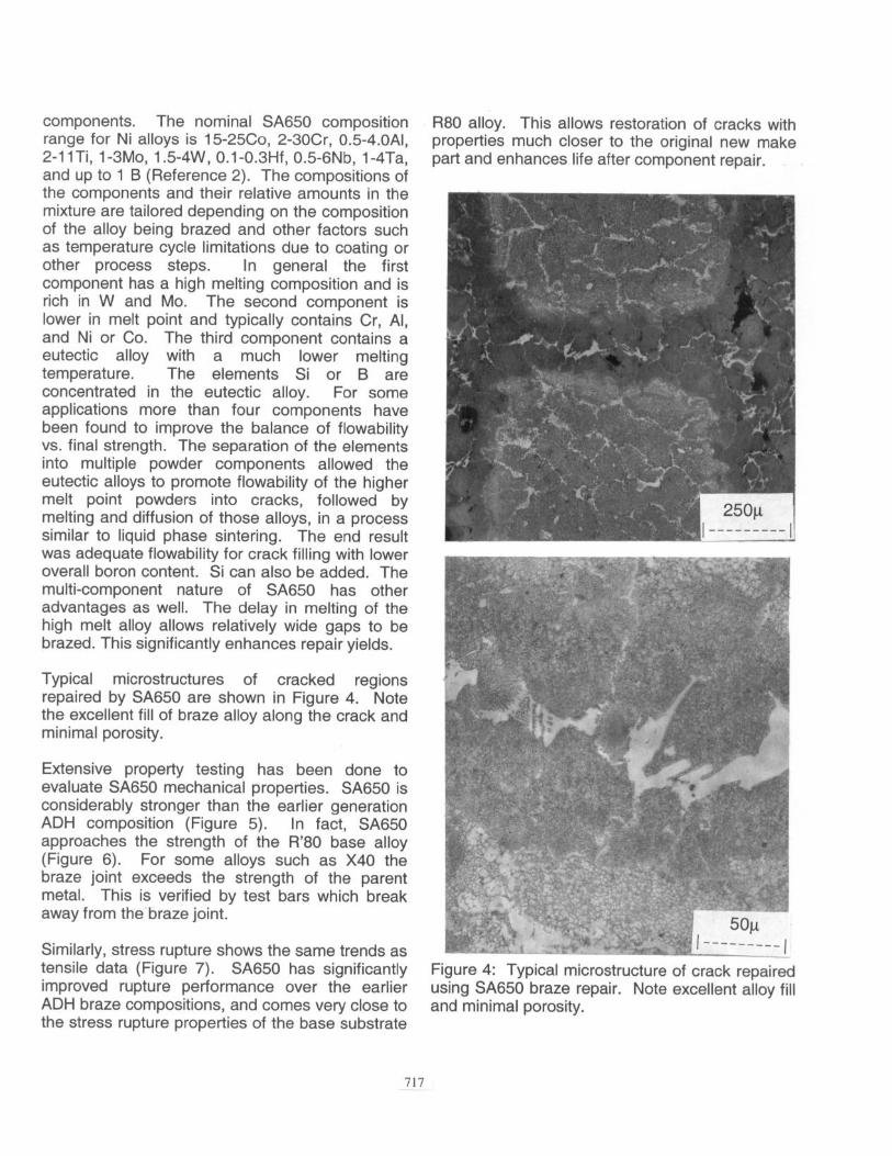
Typical microstructures of cracked regions repaired by SA650 are shown in Figure 4. Note the excellent fill of braze alloy along the crack and minimal porosity.
Extensive property testing has been done to evaluate SA650 mechanical properties. SA650 is considerably stronger than the earlier generation ADH composition (Figure 5). In fact, SA650 approaches the strength of the R’80 base alloy (Figure 6). For some alloys such as X40 the braze joint exceeds the strength of the parent metal. This is verified by test bars which break away from the braze joint.
Similarly, stress rupture shows the same trends as tensile data (Figure 7). SA650 has significantly improved rupture performance over the earlier ADH braze compositions, and comes very close to the stress rupture properties of the base substrate
R80 alloy. This allows restoration of cracks with properties much closer to the original new make part and enhances life after component repair.
Figure 4: Typical microstructure of crack repaired using SA650 braze repair. Note excellent alloy fill and minimal porosity.
717

Strength Data, SA650 vs ADH Braze Repair, 871 C
1000.0 900.0 800.0
2 700.0 z 600.0 5 500.0
q urs
B 400.0 El rnO.P% YS
g 300.0 200.0 100.0
0.0 SA850 ADH
AIIOY
Figure 5: Comparison of SA650 Braze Strength with ADH Braze Strength. SA650 is considerably stronger.
Strength Data, SA650 Braze Repair vs R80 Base Alloy, 927c
600.0 , I 500.0
E- 400.0 -- 5
300.0 q UTS
5 -- P I n 0.2% YS 2 200.0 -__ 5
100.0 --
SA650 braze repair R80 base alloy
Alloy
kgure 6: Strength comparison between SA650 braze repair alloy and baseline R80 properties. SA650 braze strength in the repaired regions of he part approaches that of the substrate alloy being repaired.
Results of fatigue testing are presented in Figure 8. Here the data is compared to R’80 base metal and properties approach common equiaxed airfoil alloys for the narrow gap test specimens which had braze gaps up to 0.13 mm, while properties were slightly lower for the wide gap specimens. The excellent fatigue performance is achieved despite the minor porosity typical of braze alloy shrinkage.
LCF failures typically occur at pores. This is common in braze repair alloys (Reference 6) due to the inherent nature of the process, Boron is a
Stress Rupture Data
24 26 28 30
Larson Miller Parameter T(2otl0gt)xo.001
Figure 7: Stress Rupture Comparison Between SA650 braze alloy, ADH braze alloy, and R80 Base metal. The improvement offered by SA650 is clear.
SA650 LCF Data, 982C
350
200 -
10 1000 100000 lE+07
Cycles to Failure
Figure 8: Low Cycle Fatigue properties of SA650 braze repair compared to baseline R80 properties
key melt point depressant used in braze alloys. The boron level of LPMTM IN738 (Reference 6) is similar to that of SA650, and SA650 displays similar failure modes. Boron has been found to influence porosity in Ni-base powder superalloys (Reference 7 and 8), thus it would be of interest to compare LCF properties with brazeability across boron levels for the same base braze composition. However, extensive testing, characterization, and field experience have shown that typical porosity levels associated with these alloys allow good performance.
718

Quality control evaluations on PACH-repaired hardware include metallurgical cutup to ensure proper braze flow and acceptable porosity for each batch. A typical repaired part is shown in Figure 9. General Electric often subjects parts to Furnace Cycle Testing (FCT) at aggressive cycle conditions to verify performance prior to release for engine application. Figure 10 shows a typical part after FCT test. The regions in the part that had prior cracks that were repaired did not fail prematurely in the test. Other regions of the part that had not been repaired showed distress and ultimate failure occurred away from brazed areas. This validates the ability of brazing, with proper alloy selection, to produce good component life after a repair. SA650 has proven itself in repair with over 100,000 airfoil components repaired successfully. The reduced metallurgical impact to the base alloy, made possible by the lower boron content, both improves the properties of the parts after the initial repair and allows multiple repairs to the components to be made, greatly reducing operating costs for airlines. Parts repaired by SA650 are now performing successfully on a daily basis.
25mm
I----I
Figure 9: Typical part at completion of repair process.
20mm I_----I
Figure 10: Results of FCT testing of an advanced braze alloy. This part had been engine run in service, repaired using techniques described in the text, and Furnace Cycle tested. Eventual part failure occurred at a crack away from any previous repaired regions, demonstrating the capability of braze repair.
References:
1 .Wayne A. Demo and Stephen J. Ferrigno, “Brazing Method Helps Repair Aircraft Gas- Turbine Nozzles”, Advanced Materials and Processes, March 1992, pp. 43-45.
2.S. J. Ferrigno, M. Somerville, and W. R. Young, U. S. Patent 4,830,934, May 16, 1989.
3.D. L. Keller and W. R. Young, Cost Effective Repair Techniques for Turbine Airfoils - Volume 1, Air Force Report AFWAL-TR-81- 4009, Volume 1, Contract F33615-78-5134, Wright-Patterson AFB, Ohio, 45433, June 1981).
4.D. L. Keller and D. L. Resor, U.S. Patent 4,098,450, Superalloy Article Cleaning and Repair Method, July 4, 1978.
5.D. L. Keller and W. R. Young, Cost Effective Repair Techniques for Turbine Airfoils -
719

Volume 2, Air Force Report AFWAL-TR-81- 4009, Volume 2, Contract F33615-78-5134, Wright-Patterson AFB, Ohio, 45433, April 1982)
6.Keith A. Ellison, Joseph Liburdi and Jan T. Stover, “Low Cycle Fatigue Properties of LPMTM Wide-Gap Repairs in lnconel 738”, in Superalloys 1996, ed. by R. D. Kissinger et. al., TMS-AIME, 1996, pp. 763-773.
7.E. S. Huron, R. L. Casey, M. F. Henry, and D. P. Mourer, “The Influence of Alloy Chemistry and Powder Production Methods on Porosity in a P/M Nickel-Base Superalloy, in Superalloys 1996, ed. by R. D. Kissinger et. al., TMS- AIME, 1996, pp. 763-773.
8. E. S. Huron, U.S. Patent No. 5584,948, Method for Reducing Thermally-Induced Porosity in a Polycrystalline Nickel-Base Superalloy Article, December 17,1996.
720