Embed Size (px)
Citation preview
Brassey, Charlotte and Maidment, S and Barrett, P (2017)Muscle mo-ment arm analyses applied to vertebrate paleontology: a case study usingStegosaurus stenops Marsh, 1887. Journal of Vertebrate Paleontology, 37(5). ISSN 0272-4634
Downloaded from: http://e-space.mmu.ac.uk/618727/
Version: Accepted Version
Publisher: Taylor & Francis on behalf of Society of Vertebrate Paleontology
DOI: https://doi.org/10.1080/02724634.2017.1361432
Please cite the published version
https://e-space.mmu.ac.uk
1
Muscle moment arm analyses applied to vertebrate paleontology: a case study using 1
Stegosaurus stenops Marsh, 1887 2
3
CHARLOTTE A. BRASSEY,1,†,* SUSANNAH C. R. MAIDMENT,2,3 and PAUL M. 4
BARRETT4 5
6
†Current Address: School of Science and the Environment, Manchester Metropolitan 7
University, Chester Street, Manchester, M1 5GD, United Kingdom, [email protected]; 8
1School of Earth and Environmental Sciences, University of Manchester, Manchester, M13 9
9PL, United Kingdom; 10
2School of Environment and Technology, University of Brighton, Lewes Road, Brighton, 11
BN2 4GJ, United Kingdom, [email protected]; 12
3Department of Earth Science and Engineering, South Kensington Campus, Imperial College, 13
London SW7 2AZ, United Kingdom; 14
4Department of Earth Sciences, The Natural History Museum, Cromwell Road, London SW7 15
5DB, United Kingdom, [email protected] 16
17
*Corresponding author 18
19
RH: BRASSEY ET AL.—MUSCLE MOMENT ARMS OF STEGOSAURUS20
2
ABSTRACT—The moment arm of a muscle defines its leverage around a given joint. 21
In a clinical setting, the quantification of muscle moment arms is an important means 22
of establishing the ‘healthy’ functioning of a muscle and in identifying and treating 23
musculoskeletal abnormalities. Elsewhere in modern animal taxa, moment arm 24
studies aim to illuminate adaptions of the musculoskeletal system towards particular 25
locomotor or feeding behaviors. In the absence of kinematic data, paleontologists 26
have likewise relied upon estimated muscle moment arms as a means of 27
reconstructing musculoskeletal function and biomechanical performance in fossil 28
species. With the application of ‘virtual paleontological’ techniques, it is possible to 29
generate increasingly detailed musculoskeletal models of extinct taxa. However, the 30
steps taken to derive such models of complex systems are seldom reported in detail. 31
Here we present a case study for calculating three-dimensional muscle moment arms 32
using Stegosaurus stenops Marsh, 1887 to highlight both the potential and the 33
limitations of this approach in vertebrate paleontology. We find the technique to be 34
mostly insensitive to choices in muscle modeling parameters (particularly relative to 35
other sources of uncertainty in paleontological studies), although exceptions do exist. 36
Of more concern is the current lack of consensus on what functional signals, if any, 37
are contained within moment arm data derived from extant species. Until a correlation 38
between muscle moment arm and function can be broadly identified across a range of 39
modern taxa, the interpretation of moment arms calculated for extinct taxa should be 40
approached with caution.41
3
INTRODUCTION 42
43
Biomechanics is the application of mechanical principles to biological 44
systems. An understanding of how mechanical principles act to facilitate or constrain 45
biological form is essential for our understanding of adaptation and the causal link 46
between phenotype and evolutionary success (Alexander, 2003; Taylor and Thomas, 47
2014). At the level of the individual, the fundamental processes of locomotion, 48
feeding, breathing, and reproduction are strongly dictated by the geometric 49
arrangement of muscle and bone. More broadly, studies of predation, competitive 50
exclusion, adaptive radiation, and convergent evolution may all be considered in the 51
light of the musculoskeletal system. 52
Here, we focus on one particular aspect of functional anatomy, muscle 53
moment arms, or the leverage of muscles around a joint. As a geometric property, 54
moment arms can be straightforward to calculate, and have therefore been widely 55
applied to fossil taxa to elucidate evolutionary trends in biomechanical performance 56
within and between extinct lineages, and higher-level biomechanical parameters such 57
as active muscle volume and estimated energy expenditure. With the recent growth in 58
‘virtual paleontology’ (Sutton et al., 2014), increasingly advanced modeling 59
techniques are now employed to estimate muscle moment arms. Using a new 3D 60
digital reconstruction of Stegosaurus stenops (Brassey et al., 2015) as a worked 61
example, we describe in detail the steps taken when calculating muscle moment arms 62
in fossil taxa. In particular, we highlight the relative sensitivity/insensitivity of this 63
approach to modeling parameters. Additionally, we discuss what functional signals, if 64
any, are present in the muscle moment arms of extant taxa, and the degree to which 65
these signals may be discernable in fossil taxa. 66
4
67
Muscle Moment Arms in Extant Taxa 68
In biomechanics, musculoskeletal function is strongly dictated by the 69
geometry of the muscle-tendon units of the body, and the most basic descriptor of 70
muscle geometry is muscle moment arm. Torque (or moment) is the tendency for an 71
applied force to rotate an object around an axis, and is calculated as the cross product 72
of force and the lever-arm (herein ‘moment arm’) of the force system (Gregory, 73
2006). The moment arm is defined as the perpendicular distance from said axis to the 74
line of action of the force. In the context of biomechanics, a muscle moment arm can 75
be thought of as the leverage of a given muscle-tendon unit around a joint and as a 76
means of transforming muscle force into joint rotation. As such, moment arms are 77
crucial for understanding how muscles produce limb movement. In this simplified 78
lever system, larger moment arms produce larger joint moments as: 79
80
Mjoint = MA×Fmus (1) 81
82
where Mjoint is the joint moment, MA is the moment arm, and Fmus is the muscle force. 83
However, larger moment arms are also associated with a decrease in muscle 84
contraction velocity as: 85
86
w = tan-1(DLmus/MA)/t (2) 87
88
where w is the angular velocity of the joint, DLmus is the change in the length of the 89
muscle, and t is time (Channon et al., 2010). Muscle moment arms may therefore 90
5
distinguish between limbs optimized for high rotational velocity versus those 91
optimized for high torque (Stern, 1974; but see below for confounding factors). 92
Within human clinical and sports sciences, the quantification of ‘healthy’ 93
muscle moment arms is essential for the treatment of movement abnormalities and in 94
the planning of orthopedic surgeries (Arnold et al., 2000). Therefore considerable 95
effort has been invested in developing techniques for reliably estimating muscle 96
moment arms. For cadaveric material, muscle moment arm can be calculated 97
according to the classic ‘geometric’ definition (the shortest perpendicular distance 98
from the joint center of rotation to the muscle-tendon unit’s line of action) using an 99
idealized origin-insertion model, assuming each muscle is represented as a straight 100
line between origin and insertion (Karlsson and Peterson, 1992; Hughes et al., 1998; 101
see Fig. 1). 102
However, moment arm often varies with joint angle (An et al., 1984), and 103
hence muscle dynamics vary throughout the gait cycle (Williams et al., 2008). 104
Consequently, a more informative metric is the relationship between joint angle and 105
instantaneous muscle moment arm. The tendon-travel method (Spoor and van 106
Leeuwen, 1992; Otis et al., 1994) plots joint angle against tendon displacement and 107
fits linear or second/third order polynomial models to the relationship. The equations 108
can then be differentiated to give either a constant value for moment arm (as in the 109
case of linear regression) or the relationship between joint angle and moment arm (in 110
the case of polynomial equations). The tendon-travel method benefits from 111
minimizing the uncertainty associated with locating the joint center and has been 112
applied extensively to both human and non-human modern taxa (Favre et al., 2008; 113
Channon et al., 2010; Crook et al., 2010; Astley and Roberts, 2012). However, 114
concerns have been raised regarding the application of tendon-travel to the calculation 115
6
of moment arms. Sustaita et al. (2015) found considerable disagreement between 116
moment arms calculated using the ‘geometric’ definition and those calculated via 117
tendon-travel, most likely due to dynamic changes in the travel path of tendons during 118
phalangeal joint excursion causing increased tendon travel without a concomitant 119
increase in a given in-lever. Additionally, Hutchinson et al. (2014) highlighted the 120
issue of kinematic ‘cross-talk’, in which the joint coordinate system is misaligned 121
with the axis about which movement is assumed to occur (for example, the flexion-122
extension axis may deviate from the mediolateral anatomical direction: Piazza and 123
Cavanagh, 2000). Thus, physical manipulation of the joint within one plane of 124
movement will inevitably produce some motion about the others, introducing 125
additional error into tendon-travel estimates. 126
Traditionally applied, both methods for estimating moment arms assume the 127
joint to be operating solely within the plane of movement under investigation (i.e., 128
ignoring the ‘cross-talk’ described above), and involve labor-intensive dissection. 129
Increasingly, however, 3D medical imaging techniques, such as computed 130
tomography (CT), magnetic resonance imaging (MRI), and ultrasound, are being 131
employed to carry out in-vivo subject-specific quantification of muscle moment arms 132
(Sammarco et al., 1973; Kumar, 1988; Juul-Kristensen et al., 2000; Maganaris, 2004), 133
either for the purpose of surgical planning and clinical decision-making or for ex-vivo 134
quantification based on cadaveric material. These approaches avoid invasive surgeries 135
and allow joint movement to be quantified in 3D. However, calculating muscle 136
moment arms for the wide variety of limb postures assumed during habitual 137
locomotion requires extensive imaging of the patient. Therefore a combination of 138
patient-specific 3D imaging and generic computer-based musculoskeletal modeling 139
7
has become common practice in clinical biomechanics (Arnold et al., 2000 and 140
references therein). 141
142
Muscle Moment Arms Applied to the Fossil Record 143
Within the disciplines of paleontology and physical anthropology, bone 144
morphology is often the only source of information upon which to base 145
reconstructions of the behavior and phylogenetic relationships of extinct species. 146
Other information on bone material properties (elastic moduli, density) and muscle 147
architecture (fiber length, pennation angle) are either lost entirely or preserved only 148
under exceptional conditions (McNamara et al., 2010). When required for 149
biomechanical modeling approaches, such as finite element analysis (FEA) or 150
multibody dynamic analysis (MBDA), these properties must therefore be estimated 151
with reference to the extant phylogenetic bracket (EPB: Witmer, 1995a) or explicitly 152
excluded from the analysis. 153
Although soft tissues are rarely preserved in the fossil record, musculoskeletal 154
reconstructions of extinct taxa are frequently attempted (e.g., fish: Anderson and 155
Westneat, 2009; early tetrapods: Neenan et al., 2014; amphibians: Witzmann and 156
Schoch, 2013; dinosaurs: Maidment and Barrett, 2011, 2012; pterosaurs: Costa et al., 157
2013; mammals: Gill et al., 2014; birds: Tambussi et al., 2012; hominins: Nagano et 158
al., 2005; D’Anastasio et al., 2013). Furthermore, the qualitative discussion of muscle 159
moment arms is a long-established practice in vertebrate paleontology (Morton, 1924; 160
Simpson and Elftman, 1928), and the calculation of muscle moment arms has been 161
applied to the fossil record to address biomechanical questions at several levels: 162
8
1. The functioning of individual muscle-tendon units. For example, determining the 163
function of a particular muscle (i.e., flexor vs. extensor) around a given joint in an 164
individual (e.g., Bates et al., 2012a). 165
2. The functioning of musculoskeletal groups. For example, using the sum of muscle 166
moment arms around a joint to infer limb pose in an individual (e.g., Hutchinson et 167
al., 2005). 168
3. The functioning of muscle-tendon units, or musculoskeletal groups, across multiple 169
individuals. For example, using muscle moment arms to infer changes in locomotor 170
ability, feeding or other behaviors within a lineage (e.g., Bargo, 2001). 171
In the absence of soft tissues, muscle moment arms may be calculated from 172
dry skeletal/fossil remains on the basis of estimated muscle attachment sites, simple 173
2D trigonometry, and/or more complex 3D computer models. Early studies tended to 174
follow an idealized 2D origin-insertion method (e.g., DeMar and Barghusen, 1972; 175
McHenry, 1975; Emerson and Radinsky, 1980) in which each muscle is simplified to 176
one line of action, and a single value for a moment arm is calculated geometrically on 177
the basis of skeletal landmarks identifying joint centers and muscle insertions (see 178
Fig. 1). However, following the development of computer-based musculoskeletal 179
modeling within the clinical sciences, paleontologists have adopted this technique to 180
generate detailed 3D models of fossil myology including complex joints, muscle 181
geometry, and travel paths for the purpose of moment arm estimation (e.g., 182
Hutchinson et al., 2005; Chapman et al., 2010; Bates and Schachner, 2011; Bates et 183
al., 2012a, b; Maidment et al., 2014a; Costa et al., 2013). Both approaches have merit, 184
and both are still commonly applied to calculate the muscle moment arms of extinct 185
taxa. 186
9
Van Der Helm and Veenbaas (1991) identified two phases in assessing the 187
mechanical behavior of a system: 1) deriving an adequate model of the system and; 2) 188
using the model to calculate forces, stresses, and motions. In the case of the 189
musculoskeletal system, once a model has been created, the calculation of muscle 190
moment arms, muscle force, joint torque, etc., is relatively straightforward and has the 191
potential to generate a vast quantity of data very quickly. In some cases, however, 192
only the results of the analyses are discussed in detail, whereas the steps taken to 193
derive a simplified model of a fossil from such a complex system may be poorly 194
described or absent entirely. 195
Elsewhere, considered reviews of paleontological FEA have highlighted the 196
sensitivity of model results to input parameters and cautioned against their over-197
interpretation (Rayfield, 2007; Bright, 2014), reflecting a growing concern within the 198
field over the exponential growth in the number of fossil biomechanics studies with 199
comparatively little validation on extant taxa (Anderson et al., 2011; Brassey, in 200
press). Here we contribute to this discussion by reviewing the procedure for 201
calculating muscle moment arms using 3D musculoskeletal models of fossil species, 202
highlighting the steps that involve user subjectivity and potential sources of 203
uncertainty in model parameters. Whilst the growth in graphics-based computational 204
models has made it possible to create increasingly complex and arguably more 205
‘realistic’ biomechanical models of fossil taxa, this has been at a cost. Much of the 206
literature surrounding musculoskeletal models of fossil species is an impenetrable 207
‘black-box’ to non-specialists (Anderson et al., 2011) as methodologies are often 208
sparse in detail or relegated to supplementary materials (although see Domalain et al., 209
2016; Lautenschlager, 2016). Furthermore, the sensitivity of model results to input 210
10
parameters are not always fully explored (although see Hutchinson et al. [2005] and 211
Bates et al. [2012a] for sensitivity analyses on fossil muscle reconstructions). 212
Here we present a workflow for the generation of a musculoskeletal model of 213
a specific fossil individual and the subsequent calculation of muscle moment arms. 214
We aim to improve transparency with regard to model creation, whilst emphasizing 215
the potential utility of this approach and drawing attention to its limitations. Previous 216
studies have addressed these issues in the context of clinical human anatomy (Hicks et 217
al., 2014 and references therein), but we highlight additional issues that are solely the 218
concern of those working on fossil material. Furthermore, we consider which 219
functional signals (if any) are discernable within the muscle moment arm data of 220
extant taxa, and therefore what we might reasonably expect to find from an equivalent 221
paleontological study. 222
The capacity of a given muscle to generate torque around a joint is a function 223
of both its force-generating capability (as defined by physiological cross-sectional 224
area) and its moment arm. Multibody dynamic analyses employing forward- or 225
inverse-dynamic simulations of locomotion (Sellers and Manning, 2007; Sellers et al., 226
2009, 2013), biting (Bates and Falkingham, 2012; Lautenschlager et al., 2016) and 227
head and neck movements (Snively et al., 2013) in fossil species are also reliant upon 228
estimates of both muscle architecture and muscle moment arms. The following 229
discussion is therefore highly relevant to those creating musculoskeletal models for 230
the purpose of MBDA and FEA on extinct species. 231
232
MODEL CONSTRUCTION 233
234
11
The specimen used as an example herein is a sub-adult individual of the 235
ornithischian dinosaur Stegosaurus stenops Marsh, 1887 (NHMUK [Natural History 236
Museum, London, U.K.] PV R36730), collected from the Upper Jurassic Morrison 237
Formation of Wyoming, U.S.A. This specimen is the most complete Stegosaurus 238
found to date, with over 80% of the body represented (Brassey et al., 2015; Maidment 239
et al., 2015). The specimen was digitized as disarticulated elements using 240
photogrammetric protocols described elsewhere (Falkingham, 2012; Mallison and 241
Wings, 2014) and the freely available photogrammetry software ‘VisualSFM’ 242
(http://ccwu.me/vsfm) and ‘Meshlab’ (http://meshlab.sourceforge.net) and the 243
reconstructed articulated skeleton was posed in 3DsMax 244
(www.autodesk.com/3dsmax) (see Fig. 2). Details regarding the extent of 245
missing/repaired elements and degree of taphonomic damage are reported elsewhere 246
(Maidment et al., 2015). Likewise, the procedure for rearticulating the digital model is 247
documented in Brassey et al. (2015). 248
Muscle moment arm analysis was carried out in ‘Gaitsym’ 249
(http://www.animalsimulation.org; Sellers and Manning, 2007). Whilst we take a 3D 250
graphics-based computational approach to calculating moment arms of the 251
appendicular skeleton, much of our discussion is also applicable to the classic 2D 252
origin-insertion method frequently employed by paleontologists and to 253
musculoskeletal reconstructions of the skull. 254
The procedure for model creation is described in detail below. Briefly, 255
muscles were reconstructed on the basis of stegosaurian limb myology, as 256
reconstructed by Maidment and Barrett (2012), including 13 muscles in the forelimb 257
and 19 in the hind limb. In addition, pairs of antagonistic puppet-string ‘driver’ 258
muscles were attached for the purpose of driving the limbs from maximal theoretical 259
12
flexion to maximum theoretical extension (see Fig. 2 and ‘Joint Ranges of Motion’, 260
below, for more detail). Alternatively, pre-existing muscles within the model can be 261
used for this purpose, assuming the geometry of the muscle is such that the maximum 262
flexion/extension can be achieved when the muscle is activated. Whichever 263
mechanism is used to drive the limb through flexion-extension (either by the puppet-264
string muscles, or by firing off the pre-existing muscles intrinsic to the model), joint 265
limits are predetermined (see below) and will remain the same, as will the resulting 266
moment arms. 267
Moment arms were calculated according to the classic geometric definition 268
(shortest perpendicular distance from joint center to muscle line of action) as opposed 269
to the tendon travel method, although both will result in the same answer using the 3D 270
modeling approach presented herein. As the model comprised several bi-articular 271
muscles (muscles that travel across two joints), joints in the limb other than the one 272
under investigation were locked in all planes of movement during the analysis, as is 273
common practice in paleontology and modern cadaveric experiments (Channon et al., 274
2010). Pairs of driver muscles were activated in sequence (each activation lasting 0.5 275
seconds) to drive the limb segment through its full range of motion from its original 276
neutral posture whilst instantaneous moment arms were calculated for every muscle at 277
a default interval of 0.0001 seconds. Joint angle and moment arms were exported to 278
‘R’ (R Core Team, 2016) and plotted using a cubic smoothing spline (smooth.spline 279
function within the ‘stats’ package). 280
281
Articulation of the Skeleton 282
Every mechanical model begins with at least two rigid bodies (in this case, 283
bones) connected by a kinematic constraint (in this case, a joint). When generating a 284
13
musculoskeletal model of an extant individual, skeletal geometry is often derived 285
from a CT or MRI scan of the intact body and the articulation of the skeleton is 286
therefore relatively well constrained. In the case of fossil taxa, however, the skeleton 287
may be digitized as disarticulated elements (as in the case of Stegosaurus presented 288
here) or as a museum-mounted specimen (Maidment et al., 2014). In either scenario, 289
the absence of associated soft tissues requires subjective decisions to be made 290
regarding the rearticulation of the skeleton. 291
Although the preservation of calcified cartilage in fossil long bones has been 292
widely reported (Holliday et al., 2010 and references therein), the non-ossified 293
epiphyseal joint cartilage (chondroepiphysis) that would have capped the ends of 294
bones is rarely fossilized (Chinsamy-Turan, 2005). In extant archosaurs, removal of 295
the chondroepiphysis accounts for a 5–9% decrease in long bone length in the limbs 296
of Alligator mississippiensis and 0–10% in a range of modern birds (Holliday et al., 297
2010). Previous studies of fossil muscle moment arms have attempted to correct for 298
this missing cartilage. In a study on the hind limbs of Tyrannosaurus rex, Hutchinson 299
et al. (2005) added 7.5% to the length of the femur, 5% to that the tibia, and 10% to 300
metatarsus length on the basis of an undescribed set of cartilage measurements from 301
extant taxa. In other studies limb bones are clearly spaced apart, yet no specific 302
reference is made to the size of spacing, nor how this value was calculated (e.g., Bates 303
et al., 2012a, b). 304
Failure to account for missing articular cartilage has the effect of shortening 305
the effective segment length and bringing muscle origin and insertion points closer 306
together. As an example, Figure 3 illustrates the effect of incorporating articular 307
cartilage on moment arm values for the M. iliofibularis (IFB) measured around the 308
knee during knee flexion. IFB was modelled as travelling in a straight path from 309
14
origin to insertion without passing through via points or around cylinders (see Muscle 310
Paths, below). For a discussion of the process of estimating joint center locations, see 311
Joint Centers, below. The effect of missing articular cartilage on calculated moment 312
arms varies with joint angle (Fig. 3) with the discrepancy between models with and 313
without cartilage increasing with knee flexion. When accounting for an additional 314
(worst-case scenario) 10% of long bone length as cartilage (Fig. 3C), the maximum 315
value calculated for IFB moment arm is 26% greater than when cartilage is ignored. 316
However, if the joint center is shifted distally to maintain an equal distance between 317
muscle insertion and center of rotation when adding cartilage (Fig. 3D), this 318
discrepancy is considerably reduced. In modern taxa, the extent to which joint center 319
locations differ between those calculated in-vivo, versus those based on dry articular 320
surfaces missing cartilage, is unknown (see later section ‘Joint Centers’). 321
Given that high variability has been documented in long bone cartilage 322
thickness among extant birds (within Galliformes, cartilage accounts for 10% of 323
femoral length in Gallus gallus and 1% in Coturnix japonica: Holliday et al., 2010) it 324
is reasonable to predict that such disparity might also have characterized extinct 325
clades. When generating muscle moment arm data across a comparative sample of 326
fossil taxa, for example, the dinosaurian clades Ornithischia (Maidment et al., 2014a) 327
or Allosauroidea (Bates et al., 2012b), it is prudent to consider that interspecific 328
variability in cartilage thickness will overlie any hypothesized functional signal in 329
muscle moment arms, and may affect the interpretation of the dataset. In extant 330
mammals, a significant negative allometric relationship exists between body mass and 331
femoral condyle cartilage thickness (Malda et al., 2013). A similar pattern has also 332
been identified in ontogenetic samples of Alligator and Numida, in which smaller 333
individuals possess a relatively greater thickness of chondroepiphysis to total bone 334
15
length (Bonnan et al., 2010). Should this relationship prove consistent across modern 335
birds or reptiles, it would prove useful in constraining hind limb joint spacing in 336
comparative samples of fossil archosaur taxa. 337
Likewise, the loss of intervertebral fibrocartilagenous disks or synovial 338
capsules from between adjacent vertebrae in extinct taxa has the effect of shortening 339
the length of the reconstructed vertebral column. This effect has previously been 340
discussed in the context of estimated neck flexibility and range of motion (Mallison, 341
2010a; Cobley et al., 2013; Taylor and Wedel, 2013) and as a potential source of 342
uncertainty in volumetric mass estimates (Brassey et al., 2015). Additionally, for 343
muscles originating from the tail (e.g., M. caudofemoralis longus in archosaurs) or 344
thorax (e.g., M. latissimus dorsi and M. trapezius in tetrapods), the incorporation of 345
additional spacing to account for intervertebral soft tissues will also impact calculated 346
muscle moment arms in a similar manner to epiphyseal cartilage, as discussed above. 347
Furthermore, placement of the scapula relative to the ribcage has a knock-on effect on 348
the location of the shoulder joint relative to the thorax. Whilst mounted skeletons are 349
often characterized by the scapula immediately overlying the ribs, the volume of soft 350
tissue separating the skeletal elements has not been quantified in extant taxa. 351
In addition to joint spacing, the joint morphology of extinct taxa can be 352
altered, both due to the removal of cartilage and other soft tissues though the process 353
of fossilization (Bonnan et al., 2010), and due to subsequent taphonomic deformation 354
and weathering. This can increase uncertainty with regards to the orientation and 355
positioning of skeletal elements, and further hamper efforts during rearticulation. In 356
the case of Stegosaurus (NHMUK PV R36730), for example, the degree of 357
mediolateral flaring of the pubis and ischium is open to interpretation. 358
16
In ornithischian dinosaurs, the prepubis is an anterior extension of the pubis 359
arising from its proximal margin and extending anterior to the acetabulum. This 360
process acts as an origin for the M. ambiens (AMB), which subsequently inserts onto 361
the cnemial crest of the tibia (Maidment and Barrett, 2011). When reconstructing the 362
Stegosaurus model, the pubis and ischium were rearticulated with the ventral surface 363
of the ilium to form the borders of an open acetabulum using the orientations of their 364
articular surfaces as a guide. However, the angles at which the paired pubes and ischia 365
extend with respect to the midline are uncertain. Whilst the paired pubes must be in 366
contact distally, the contact between the iliac articulation of the pubis and the pubic 367
peduncle of the ilium is less well constrained by osteology. Figure 4 illustrates the 368
effect of varying the angle of the pubis relative to the midline on AMB flexion-369
extension (FlexExt), abduction-adduction (AbdAdd), and long-axis rotation (LAR) 370
moment arms calculated at the hip during hip flexion-extension. The pubis was 371
modeled in two orientations: a) with the long axes of the pubes aligned parallel to the 372
iliac blades (Fig. 4A), which are themselves extremely flared in the mediolateral 373
direction, with their distal ends meeting at a ventral midline symphysis; and b) with 374
the long axes of the pubes rotated medially from this initial position, with distal ends 375
meeting in a symphysis but with less extreme flaring (Fig. 4B). 376
Predictably, rotating the pubis medially does not impact upon the flexion-377
extension moment arm of AMB, and the functioning of the muscle remains consistent 378
as a flexor. Likewise, AbdAdd moment arms for both model configurations suggest 379
AMB functions as a hip abductor as the origin as path of the muscle remains lateral to 380
the hip joint throughout the range of motion. When the pubis is rotated medially, 381
average AbdAdd moment arm does decrease from 0.23 to 0.14 m, however, due to the 382
muscle path shifting closer to the joint center. Interestingly LAR moment arms in the 383
17
flared pubis model suggest a lateral rotation function at values of hip flexion between 384
35–60° (Fig. 4A), whereas AMB acts as a medial rotator throughout most of the 385
range of motion in the medial pubis model, switching to lateral rotation only at very 386
high values of flexion (>50°) and representing a small change in predicted muscle 387
function between the two models. 388
Uncertainty with regards to skeletal articulation therefore has the potential to 389
affect not only the magnitude of calculated muscle moment arms, but also the inferred 390
function of the muscle unit itself. This highlights the importance of having a strong 391
grounding in both the osteology and myology of the study taxa and in conducting 392
sensitivity analyses, not only to quantify uncertainty in muscle attachment sites, as has 393
previously been the case (Hutchinson et al., 2005; Bates et al., 2012a), but also to 394
investigate the effects of uncertainty in skeletal articulation. 395
Finally, the neutral stance in which the model is posed must be clearly stated 396
in order to facilitate comparisons between species and across studies. For some 397
muscles, moment arm values calculated with respect to a given joint axis are highly 398
sensitive to the joint angle about one or both of the other axes (O’Neill et al., 2013), 399
as highlighted by the issue of ‘cross talk’ when estimating extant moment arms via the 400
tendon-travel method (Hutchinson et al., 2014; see Introduction). For the estimation 401
of hind limb muscle moment arms in dinosaurs, a standard neutral hip posture of 0° 402
extension, 10° abduction, and 0° long axis rotation has been broadly agreed upon 403
(Hutchinson et al., 2005; Bates and Schachner, 2011; Bates et al., 2012a; Maidment et 404
al., 2014a), a convention that we follow herein. Comparatively little work has been 405
carried out on the moment arms of forelimb muscles in extinct taxa using 3D 406
musculoskeletal models (although geometric 'dry-bone' analyses do exist: Fujiwara 407
and Hutchinson, 2012; Martín-Serra et al., 2014). We therefore assume a neutral 408
18
shoulder posture of 30° retraction, 10° abduction, and 0° long axis rotation, following 409
this earlier work. 410
Undoubtedly, the selection of a ‘neutral posture’ does introduce a degree of 411
uncertainty and places unnecessary emphasis on reconstructing the standing posture 412
of individual taxa. When undertaking a comparison between several species of 413
differing bone morphology, the degree of osteological rotation around the long axis of 414
the bone, or extent of valgus, may vary. In such an instance, identifying an 415
‘equivalent’ starting point for a moment arm analysis may prove problematic. An 416
alternative way forward may be to follow the protocol used in biplanar X-ray imaging 417
studies (M. F. Bonnan, pers. comm., January 2017), in which the bones may be posed 418
in a flat plane or a folded position (Bonnan et al., 2016). Such reference postures 419
might be anatomically unfeasible, but are more easily replicated across a wide range 420
of taxa of diverse morphology and would provide a more consistent starting point for 421
comparative muscle moment arm studies. 422
423
Joint Ranges of Motion 424
Muscle moment arm can change as a function of joint angle (An et al., 1984) 425
and it is common practice to report moment arm values calculated as a limb is moved 426
through its full range of motion (ROM) in a particular plane. In Figure 4, for example, 427
the hip joint is moved from full flexion (-60°) to full extension (60°), assuming a 428
neutral posture of 0° in which the femur is held perpendicular to the ground in the 429
sagittal plane. It is important to emphasize that the selection of the joint ROM is 430
entirely under the control of the user. That is, whilst it is possible to calculate a value 431
for muscle moment arm for absolutely any joint angle (including angles at which the 432
19
limb would be entirely disarticulated), it is at the discretion of the user to constrain the 433
ROM to within probable biomechanical limits. 434
For example, Maidment et al. (2014a) compared hind limb muscle moment 435
arms calculated for a diverse sample of ornithischian dinosaurs across a hip flexion-436
extension ROM of -60° to 60°. Whilst this approach of comparing species across a 437
fixed ROM simplifies comparisons, it does raise a teleological issue. The 438
biomechanical feasibility of each individual achieving such a ROM in-vivo is not 439
taken into account, and on the basis of osteological and myological reconstructions it 440
is considered highly unlikely that some species (including this specimen of 441
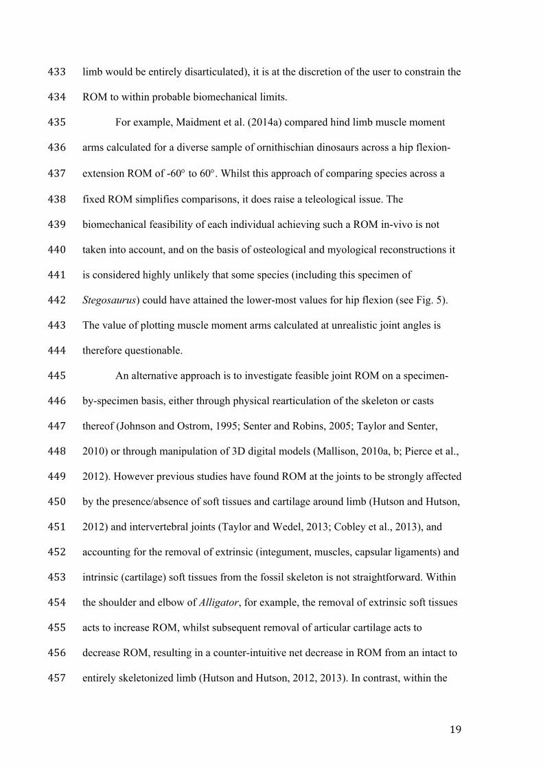
Stegosaurus) could have attained the lower-most values for hip flexion (see Fig. 5). 442
The value of plotting muscle moment arms calculated at unrealistic joint angles is 443
therefore questionable. 444
An alternative approach is to investigate feasible joint ROM on a specimen-445
by-specimen basis, either through physical rearticulation of the skeleton or casts 446
thereof (Johnson and Ostrom, 1995; Senter and Robins, 2005; Taylor and Senter, 447
2010) or through manipulation of 3D digital models (Mallison, 2010a, b; Pierce et al., 448
2012). However previous studies have found ROM at the joints to be strongly affected 449
by the presence/absence of soft tissues and cartilage around limb (Hutson and Hutson, 450
2012) and intervertebral joints (Taylor and Wedel, 2013; Cobley et al., 2013), and 451
accounting for the removal of extrinsic (integument, muscles, capsular ligaments) and 452
intrinsic (cartilage) soft tissues from the fossil skeleton is not straightforward. Within 453
the shoulder and elbow of Alligator, for example, the removal of extrinsic soft tissues 454
acts to increase ROM, whilst subsequent removal of articular cartilage acts to 455
decrease ROM, resulting in a counter-intuitive net decrease in ROM from an intact to 456
entirely skeletonized limb (Hutson and Hutson, 2012, 2013). In contrast, within the 457
20
neck of the ostrich, removal of both extrinsic and intrinsic soft tissues acts to increase 458
ROM (Cobley et al., 2013). A growing body of work is quantifying joint ROM both 459
in non-human mammals (Ren et al., 2008; Bonnan et al., 2016) and within the context 460
of the dinosaur EPB, although the total number of studies remains limited. In light of 461
this paucity of modern data, the conservative approach of Maidment et al. (2014a), 462
where all taxa are modelled with the same broad ROM, may be preferable. However, 463
the requirement for anatomically realistic ROM data remains an issue for MBDA of 464
locomotion, feeding, etc. 465
Furthermore, assessments of possible joint ROM tend to focus solely on bone-466
to-bone contact within the fossil limb, such as joint impingement and dislocation. For 467
example, moment arm papers dealing with hind limb muscles in extinct taxa often 468
model the bones of the pelvis and hind limb only (Hutchinson et al., 2005; Bates et 469
al., 2012a, b; Maidment et al., 2014a, b). Potential collisions with the head, arms, and 470
torso are ignored. Yet, as illustrated in Figure 5, the positioning of the ribcage can act 471
as a further constraint on joint ROM, as the extent of hip flexion is limited by the 472
potential for the femur to collide with the posterior dorsal ribs (assuming 10° 473
abduction and zero long axis rotation). However, this approach is considerably more 474
time consuming (as digital models of the thoracic vertebrae and dorsal ribs are also 475
required) and places further onus upon accurate rearticulation of the trunk, which is 476
itself subject to various assumptions (e.g., the potential range of movement between 477
the rib and its vertebral articulations, the exact geometry of the articulations, and the 478
effects on these of missing soft tissues). In our Stegosaurus model, for example, the 479
characteristic triangular ribcage present in the skeletal mounts of the American 480
Museum of Natural History and Senckenberg Museum stegosaurs is reconstructed by 481
sweeping the distal ends of the ribs anteriorly (Fig. 5). Yet ribs are frequently 482
21
damaged, taphonomically deformed (e.g., Maidment et al., 2015), or absent entirely, 483
and the extent to which this represents an accurate skeletal rearticulation is unclear. 484
Whilst the incorporation of additional body parts, such as the tail or torso, into a 485
musculoskeletal model may further constrain limb ROM, this must be balanced 486
against a concurrent increase in uncertainty regarding model articulation and also the 487
concomitant reduction in analytical sample size, which becomes limited perforce to 488
those specimens that are relatively complete. On the rare occasions when trackways 489
can be assigned confidently to fossil taxa, their gauge, stride length, and other track 490
features may also inform potential posture and limb range of motion (e.g., Alexander, 491
1989; Henderson, 2006; Hatala et al., 2016; but see Falkingham, 2014). 492
493
Muscle Definitions 494
Muscle Anatomy—Following the articulation of rigid bodies, the next stage 495
in building our biomechanical model involves reconstruction of the overlying 496
musculature. As highlighted above, it is possible to output moment arm values for an 497
array of nonsensical musculoskeletal arrangements, but we emphasize and advocate 498
the importance of grounding fossil biomechanical studies within a comprehensive 499
understanding of the anatomy of the study taxa. In the case of fossil myologies, 500
accurate reconstructions require the assimilation of two sources of information (Fox, 501
1964): 1) evidence of muscle attachment sites on bone surfaces, including scarring, 502
ridges, trochanters, and fossae; and 2) phylogenetic inference of muscle 503
presence/absence based of the anatomy of closely related extant taxa (Witmer, 504
1995a). 505
The use of osteological correlates in soft tissue reconstruction is well 506
established in vertebrate paleontology. Muscle scarring can indicate the location and, 507
22
to a limited extent, the size of a muscle attachment, and has been applied to broad 508
interspecific samples of taxa to trace the evolution of cranial (Witmer, 1995b; 509
Holliday, 2009) and postcranial musculature (Hutchinson, 2001a, b; Maidment and 510
Barrett, 2012). Muscles inserting via tendons or aponeuroses tend to leave more 511
distinct scars than those inserting via fleshy attachments (Bryant and Seymour, 1990), 512
yet those without well-developed scars may still be reconstructed with a reasonable 513
level of confidence (Hutchinson and Carrano, 2002) particularly when placed within a 514
phylogenetic context (see below). The correspondence between the location of 515
attaching muscles and resulting scars has been validated in extant taxa, in both the 516
skull (Hieronymus, 2006) and postcrania (Hutchinson, 2002; Meers, 2003), although 517
recent research has cautioned against the interpretation of scar morphology as 518
representative of original muscle size and/or action (Zumwalt, 2006). 519
Application of the EPB approach can further constrain soft tissue inferences 520
(Bryant and Russell, 1992; Witmer, 1995a). At its most straightforward, the EPB 521
places fossil taxa within the phylogenetic context of their closest related extant taxa, 522
with any condition present in both extant taxa being inferred as present in their last 523
common ancestor and in all of its descendants. For the purpose of estimating moment 524
arms, the EPB also has the advantage of permitting the reconstruction of muscles that 525
lack distinct attachment scarring. Furthermore, application of the EPB to soft tissue 526
restoration involves a ‘hierarchy of inferences’ and reconstructions are assigned to 527
levels I, II, or III depending upon the degree of speculation involved (Witmer, 1995a). 528
This categorization therefore allows the degree of uncertainty in reconstructed 529
myology to be recorded and communicated. Depending on the taxa of interest, 530
however, the EPB can be relatively broad and encompass modern taxa that may be 531
too functionally divergent from the fossil species to provide a basis for useful 532
23
comparisons (for example, extant amphibious crocodiles form part of the EPB for 533
extinct flying pterosaurs). This highlights the importance of grounding fossil muscle 534
reconstructions in a detailed understanding of the complexity and variability that 535
characterizes modern taxa, and the value of traditional anatomical descriptions as a 536
necessary precursor to further functional analyses. 537
To Clump or To Split?—Every biomechanical model represents a trade-off 538
between realism, precision, and generality, and in the case of musculoskeletal models, 539
this trade-off is particularly evident in myological reconstructions. The detail required 540
of a musculoskeletal model is a function of the question under investigation. In some 541
instances, all muscles acting around a particular joint are reconstructed in order that 542
the sum total moment arm may be estimated and limb posture inferred (Hutchinson et 543
al., 2005; Payne et al., 2006; Maidment et al., 2014a). In other instances, when the 544
question under consideration seeks to address an aspect of biomechanical 545
performance across a large comparative sample, only ‘major muscles’ may be 546
reconstructed. Biomechanical models of the masticatory system of fossil mammals, 547
for example, often include only the major jaw adductors, the M. temporalis and M. 548
masseter, in moment arm calculations (Iuliis et al., 2001; Bargo, 2001; Vizcaíno and 549
Iuliis, 2003; Cassini and Vizcaíno, 2012). In such instances, the decision regarding 550
which muscles to include is often made on the basis of reconstructed muscle volume 551
(i.e., smaller muscles are more likely to be excluded). 552
Kappelman (1988) took the approach of grouping a suite of muscles together 553
as a functional unit on the basis of their shared travel path around a joint. When 554
estimating the moment arm of extensor muscles crossing the knee in bovids, for 555
example, Kappelman (1988) considered all members of the Mm. quadriceps femoralis 556
group collectively as having a shared moment arm, as they all converge on the 557
24
patellar tendon and pass over the surface of the patella at an equal distance from the 558
joint center. A similar approach has also been taken when modelling the Mm. 559
quadriceps femoralis group around the human knee (Herzog and Read, 1993). 560
Likewise, when joint surfaces are modelled as cylinders in multibody dynamic 561
packages, such as Gaitsym and OpenSim (http://opensim.stanford.edu/: Delp et al., 562
2007), the minimum value for the moment arms of all muscles passing around the 563
joint will be constrained as the radius of the cylinder and hence will be equal (see 564
Geometric Shapes, below). This incorporation of isolated muscles into functional 565
groups is particularly important when musculoskeletal models are to be used as the 566
basis for forward dynamic modelling of movement. In this scenario, the addition of 567
each extra muscle increases the dimensionality of the optimal control search space 568
and causes a huge increase in terms of the cost of the simulation (Sellers et al., 2013), 569
and recent fossil gait simulation studies have therefore restricted themselves to 570
modeling generic ‘knee flexors’ and ‘hip extensors’, for example (Sellers et al., 2009). 571
In extant taxa, however, the separate heads of a single muscle have 572
occasionally been found to possess very different moment arms around the same joint 573
(e.g., equine M. biceps femoris and M. gastrocnemius: Crook et al., 2010). Different 574
subunits of a single muscle may therefore be recruited for a different function during 575
activation (Ackland et al., 2008). The corollary of grouping muscles by function, 576
therefore, is that it may be necessary to model a single muscle as two separate 577
functional units, particularly when osteological evidence suggests the presence of two 578
distinct heads. For example, Bates et al. (2012a) modeled two aspects of the M. 579
iliofemoralis (cranial and caudal), corresponding to the M. iliotrochantericus caudalis 580
and M. iliofemoralis externus, respectively, in extant birds. Even if both heads are 581
25
found to have similar moment arms, modelling them as separate muscle-tendon units 582
allows for potential functional differentiation in future forward dynamic analyses. 583
Ultimately, the decision to group or to split muscles on the basis of function 584
reflects a compromise between modelling the intricacy we know to characterize 585
modern musculoskeletal systems, and the computing time and degree of uncertainty 586
we must accept if we attempt to include such complexity into our models of extinct 587
taxa. 588
Muscle Origins and Insertions—While some muscles are characterized by 589
possessing discrete ‘heads’ as discussed above, others are large and fan-shaped with 590
broad attachment sites lacking distinct segregations. Single lines of action spanning 591
from origin to insertion cannot adequately describe the geometry of such muscles, and 592
multiple lines of action with independent origins and insertions may need to be 593
designated a priori (van der Helm and Veenbaas, 1991). Travel paths originating at 594
opposing positional extremes within a given muscle are expected to pass across the 595
joint at different locations, and therefore possess different values of muscle moment 596
arm. 597
When subdividing fan-shaped muscles, the criteria for selecting the number 598
and location of multiple lines of action are not always made clear, and may be related 599
to position (‘superficial’ vs. ‘deep’), perceived function, or selected in order to 600
capture differing fiber directions within the muscle. The practice of partitioning 601
muscles with large attachment sites is common in human biomechanical modelling 602
(Delp et al., 1990; van der Helm and Veenbaas, 1991; Holzbaur et al., 2005; 603
Chadwick et al., 2009; Arnold et al., 2010; Webb et al., 2012) and is increasingly 604
applied to other extant taxa, particularly in MBDA of skull function (Wroe et al., 605
2007, 2013; Gröning et al., 2013; Watson et al., 2014). Modern studies benefit from 606
26
the incorporation of dissection data and MRI-based imaging of in-situ 3D muscle 607
geometry when subdividing muscles for this purpose. In contrast, the representation 608
of large muscles in paleontological models ranges from single lines of action (with the 609
origin located at the centroid of the attachment site: Ravosa, 1996), to separate bodies 610
representing the two extremes in attachment location (typically anterior-most vs. 611
posterior-most positions, or preacetabular vs. postacetabular: Hutchinson et al., 2005; 612
Bates et al., 2012a; Maidment et al., 2014a), to several lines of action (McHenry et al., 613
2007; D’Anastasio et al., 2013; Gill et al., 2014). 614
To illustrate this point, we model the M. latissimus dorsi (LAT) of 615
Stegosaurus, a large fan-shaped dorsolateral muscle located posterior to the shoulder 616
joint that is responsible for humeral retraction (Meers, 2003; Dilkes et al., 2012). The 617
scapula is considered fixed relative to the trunk, and the shoulder is modelled as a 618
simple hinge joint permitting only flexion-extension. LAT is simplified into five lines 619
of action, originating from the neural spines and transverse processes of dorsal 620
vertebrae 3–7, travelling posterior to the shoulder joint and attaching at a common 621
insertion point on the posterior shaft of the humerus ventral to the head (Fig. 6). 622
Tendon length is, of course, another unknown parameter in model construction. If the 623
tendon of LAT was long, and the fibers of LAT merged onto the tendon prior to 624
passing around the shoulder joint, the LAT can be considered to have effectively a 625
single moment arm. However, assuming the tendon was short, LAT would have had 626
numerous lines of action around the joint, and therefore a range of moment arm 627
values. Travel paths were modified by via points located on the rib tubercula, lateral 628
margins of the dorsal ribs and the lateral surface of the scapula blade to prevent 629
intersection with the skeleton (see Muscle Paths, below). 630
27
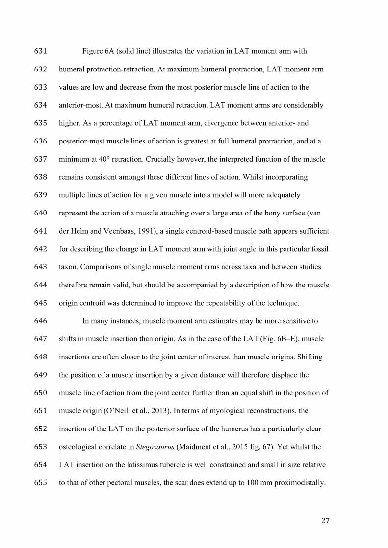
Figure 6A (solid line) illustrates the variation in LAT moment arm with 631
humeral protraction-retraction. At maximum humeral protraction, LAT moment arm 632
values are low and decrease from the most posterior muscle line of action to the 633
anterior-most. At maximum humeral retraction, LAT moment arms are considerably 634
higher. As a percentage of LAT moment arm, divergence between anterior- and 635
posterior-most muscle lines of action is greatest at full humeral protraction, and at a 636
minimum at 40° retraction. Crucially however, the interpreted function of the muscle 637
remains consistent amongst these different lines of action. Whilst incorporating 638
multiple lines of action for a given muscle into a model will more adequately 639
represent the action of a muscle attaching over a large area of the bony surface (van 640
der Helm and Veenbaas, 1991), a single centroid-based muscle path appears sufficient 641
for describing the change in LAT moment arm with joint angle in this particular fossil 642
taxon. Comparisons of single muscle moment arms across taxa and between studies 643
therefore remain valid, but should be accompanied by a description of how the muscle 644
origin centroid was determined to improve the repeatability of the technique. 645
In many instances, muscle moment arm estimates may be more sensitive to 646
shifts in muscle insertion than origin. As in the case of the LAT (Fig. 6B–E), muscle 647
insertions are often closer to the joint center of interest than muscle origins. Shifting 648
the position of a muscle insertion by a given distance will therefore displace the 649
muscle line of action from the joint center further than an equal shift in the position of 650
muscle origin (O’Neill et al., 2013). In terms of myological reconstructions, the 651
insertion of the LAT on the posterior surface of the humerus has a particularly clear 652
osteological correlate in Stegosaurus (Maidment et al., 2015:fig. 67). Yet whilst the 653
LAT insertion on the latissimus tubercle is well constrained and small in size relative 654
to that of other pectoral muscles, the scar does extend up to 100 mm proximodistally. 655
28
In Figure 6D–E, the insertion of LAT has been shifted 50 mm to its proximal-656
most position on the humerus and Figure 6A (dashed line) illustrates the effect that 657
this change has upon calculated moment arms. The impact of shifting LAT insertion 658
site is negligible at full humeral protraction, and variation introduced through the 659
positioning of muscle lines-of-action at the origin contributes more to variation in 660
LAT moment arms. With increased humeral retraction, however, variability in 661
moment arms due to insertion site position comes to dominate over variation due to 662
muscle origin. 663
For the purpose of muscle moment arm estimation, this suggests that a shift 664
towards concentrating on improving the identification of muscle insertion locations 665
would be particularly beneficial (Hutchinson et al., 2014). Exceptions will exist, 666
however, in which the joint center is located closer to muscle origin than insertion (as 667
in the case of Stegosaurus, with the origins and insertions of the M. adductor group 668
and M. iliotibialis muscles around the hip). This highlights the idiosyncratic nature of 669
muscle modelling and emphasizes the need for a muscle-by-muscle approach to 670
sensitivity analyses; the same parameters that might strongly affect the moment arm 671
of one muscle may have little or no effect on neighboring muscles acting around the 672
same joint. 673
674
Joint Definitions 675
Joint Centers—Given the geometric definition of a muscle moment arm as 676
the perpendicular distance from joint center to the muscle-tendon unit line of action, it 677
is crucial to accurately determine the position of the joint center when conducting 678
moment arm analyses. Calculated moment arms have been found to vary considerably 679
with estimated joint center in clinical human studies, and in some cases can result in a 680
29
shift in predicted function from flexion to extension (Herzog and Read, 1993). Delp 681
and Maloney (1993) estimated that a 20 mm shift in the position of the human hip 682
center may result in a change in percentage moment arms of between 0–38%, 683
dependent upon the direction of shift and the axes about which the moment arms are 684
measured. 685
Consequently, there is a considerable body of research on methods for 686
accurately determining joint centers in modern taxa, which may be broadly 687
subdivided into geometric and kinematic techniques. Kinematic joint centres are 688
calculated on the basis of instantaneous helical axes, in which the motion of an object 689
can be broken down into a rotation about and a translation along its rotational axis. 690
Kinematic joint centers can be estimated in-vivo or in-vitro via the tracking of 691
anatomical landmarks through the limb range-of-motion using motion capture 692
(Sholukha et al., 2013) or biplanar fluoroscopy (Pillet et al., 2014). 693
Geometric joint centers are calculated on the basis of fitting simple geometric 694
shapes to joint surfaces, derived from 3D coordinate measurement systems such as 695
microscribes or computed tomographic (CT)/magnetic resonance imaging (MRI) data. 696
Geometric joint centers are considered fixed throughout the range-of-motion, thus 697
ignoring possible translation of one element relative to another (see Joint Type, 698
below). In clinical human trials, joint centers calculated using kinematic and 699
geometric techniques are in broad agreement (e.g., glenohumeral joint: Veeger, 2000; 700
femoroacetabular joint: Klein Horsman et al., 2007; femorotibial joint: Eckhoff et al., 701
2003). As such, this technique can be considered applicable to disarticulated 702
skeletons, including those of extinct taxa, for which kinematic data cannot be 703
collected. 704
30
Within the paleontological literature, methodological descriptions of the 705
process of determining geometric joint centers range from detailed (Hutchinson et al., 706
2005; Fujiwara and Hutchinson, 2012) to sparse (Sellers et al., 2013) or entirely 707
absent (Sellers et al., 2009; Maidment et al., 2014b). Typically, the femoroacetabular 708
joint is identified by fitting circles and spheres to the acetabulum and femoral head 709
respectively, and subsequently aligning their centroids (Hutchinson et al., 2005; Costa 710
et al., 2013). The center of the elbow has been similarly defined as the center of the 711
radial condyle and sigmoid notch on the humerus and radius/ulna respectively, 712
calculated through the process of geometric shape fitting (Fujiwara and Hutchinson, 713
2012). Likewise, the position of the knee joint centre has been estimated by fitting 714
circles to the medial and lateral condyles, and taking the midpoint of the axis joining 715
the centers of both circles (Hutchinson et al., 2005). 716
As discussed above, the loss of articular cartilage will undoubtedly affect the 717
position of the joint center calculated through the process of shape fitting. However, 718
given the lack of data on the thickness and distribution of cartilage in extant species, it 719
is difficult to account for in extinct taxa. Taphonomic distortion of the epiphyses may 720
also impact accurate identification of joint centers. Figure 7 demonstrates the process 721
of fitting circles to the medial and lateral femoral condyles of Stegosaurus stenops. 722
Figure 7A shows the considerable extent of taphonomic warping present in the distal 723
femoral condyles, in which the condylar long axes have been rotated away from the 724
anteroposterior axis of the femur mediolaterally. First, vertices were manually 725
selected in Meshlab along a line trending anteroposteriorly across the ventral surface 726
of both condyles (Fig. 7B), hence ignoring any taphonomic distortion. Selected 727
vertices were projected onto a sagittal plane cutting through the femur, and best-fit 728
circles were fitted to the coordinates (Fig. 7D–E.) using the ‘circle fit’ function from 729
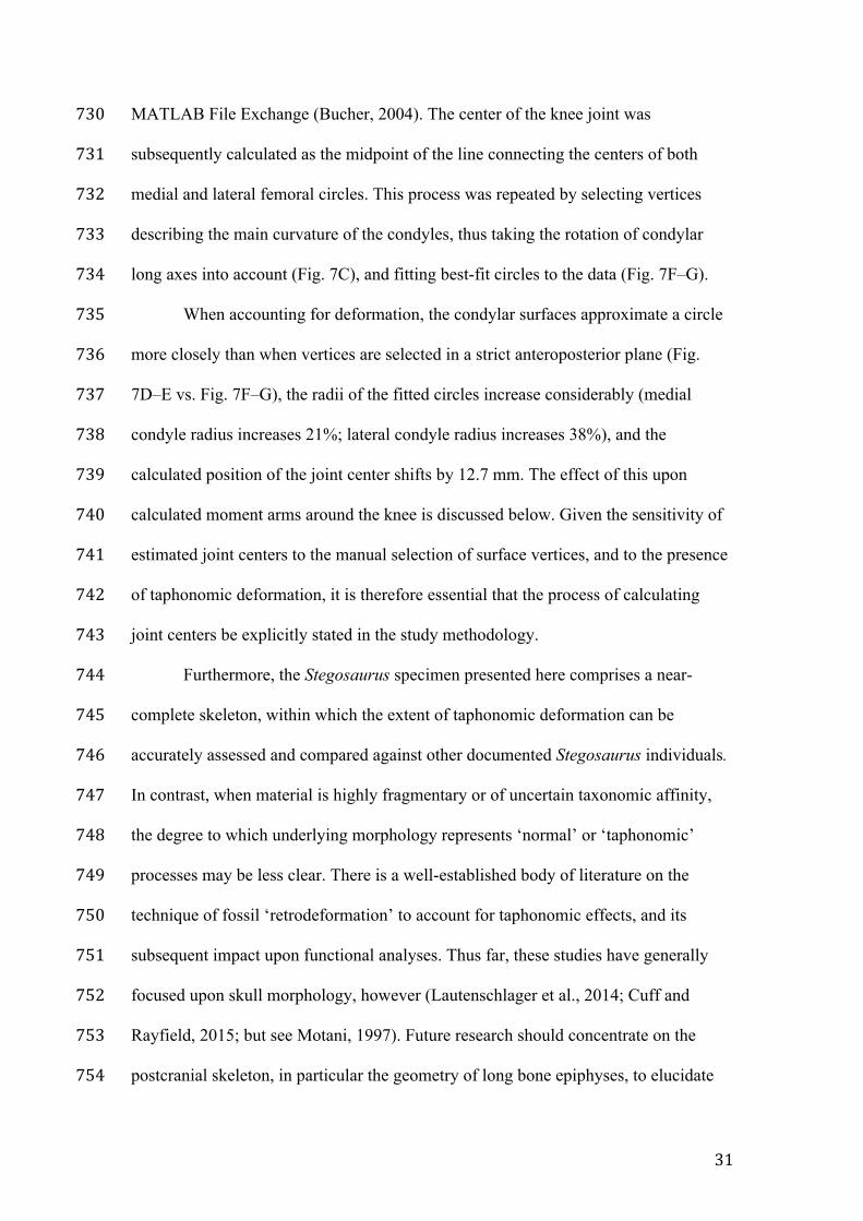
31
MATLAB File Exchange (Bucher, 2004). The center of the knee joint was 730
subsequently calculated as the midpoint of the line connecting the centers of both 731
medial and lateral femoral circles. This process was repeated by selecting vertices 732
describing the main curvature of the condyles, thus taking the rotation of condylar 733
long axes into account (Fig. 7C), and fitting best-fit circles to the data (Fig. 7F–G). 734
When accounting for deformation, the condylar surfaces approximate a circle 735
more closely than when vertices are selected in a strict anteroposterior plane (Fig. 736
7D–E vs. Fig. 7F–G), the radii of the fitted circles increase considerably (medial 737
condyle radius increases 21%; lateral condyle radius increases 38%), and the 738
calculated position of the joint center shifts by 12.7 mm. The effect of this upon 739
calculated moment arms around the knee is discussed below. Given the sensitivity of 740
estimated joint centers to the manual selection of surface vertices, and to the presence 741
of taphonomic deformation, it is therefore essential that the process of calculating 742
joint centers be explicitly stated in the study methodology. 743
Furthermore, the Stegosaurus specimen presented here comprises a near-744
complete skeleton, within which the extent of taphonomic deformation can be 745
accurately assessed and compared against other documented Stegosaurus individuals. 746
In contrast, when material is highly fragmentary or of uncertain taxonomic affinity, 747
the degree to which underlying morphology represents ‘normal’ or ‘taphonomic’ 748
processes may be less clear. There is a well-established body of literature on the 749
technique of fossil ‘retrodeformation’ to account for taphonomic effects, and its 750
subsequent impact upon functional analyses. Thus far, these studies have generally 751
focused upon skull morphology, however (Lautenschlager et al., 2014; Cuff and 752
Rayfield, 2015; but see Motani, 1997). Future research should concentrate on the 753
postcranial skeleton, in particular the geometry of long bone epiphyses, to elucidate 754
32
the effects of fossilization and potential deformation upon interpreted skeletal 755
function. 756
Joint Type—As outlined above, the geometric method of calculating joint 757
center does not require kinematic data and is solely based upon the surface contours 758
of the joint. This approach does, however, assume that the joint center remains fixed 759
relative to the two bodies. Yet in reality, many joints are characterized by some 760
degree of sliding (translation) in addition to pure rotation. Classically, movement in 761
the knee joint has been found to comprise both rolling and sliding (Iwaki et al., 2002), 762
with the condyles of the tibia sliding towards the extensor surface of the femur during 763
knee flexion (Johnson et al., 2008). Translation at the knee joint has been incorporated 764
into musculoskeletal models of modern humans (Steele et al., 2012) and chimpanzees 765
(O’Neill et al., 2013) but has not, to the authors’ knowledge, been investigated in 766
fossil species. 767
Likewise, the glenohumeral joint of the shoulder is typically considered as a 768
simplified ball-and-socket joint with minimal translation (Veeger and van der Helm, 769
2007). However, movement at the shoulder is a function of mobility at both the 770
glenohumeral joint and the scapulothoracic gliding plane, and the medial border of the 771
scapula remains in contact with, and translates/rotates relative to, the thoracic wall. 772
The contribution of scapula motion to total arm elevation (‘scapulohumeral rhythm’) 773
is relatively well known in modern humans (Inman et al., 1944; Bolsterlee et al., 774
2014), and a musculoskeletal model of the forelimb of Japanese macaques has 775
incorporated scapula movement as a triaxial gimbal joint (Ogihara et al., 2009; 776
although this model has thus far only been used in studies of bipedalism). However, 777
this only provides a first approximation of the wide range of possible scapula motions, 778
and again, we know of no paleontological musculoskeletal model in which 779
33
translation/rotation of the scapula is included. Similarly, biomechanical models of 780
feeding in fossil taxa often assume a simplified hinge for the jaw joint (e.g., Bates and 781
Falkingham, 2012; Wroe et al., 2013; Lautenschlager et al., 2015; but see Snively et 782
al., 2015) despite some degree of translation and/or long-axis rotation being present in 783
both mammal (Noble, 1973; Terhune et al., 2011) and reptile (Jones et al., 2012) jaws. 784
Currently kinematic data on joint translation in non-human species are 785
extremely sparse and, as a result, any attempt to incorporate movement of the joint 786
center into models of fossil species would be speculative. Furthermore, the 787
importance of incorporating translation into joint mobility will vary across taxonomic 788
groups (e.g., between mammals and archosaurs). In contrast, the calculation of a fixed 789
center of rotation based solely on joint geometry is comparatively simple, repeatable 790
and widely applicable across a broad range of paleontological specimens. Ultimately, 791
the degree of complexity incorporated into fossil reconstructions should be a function 792
of the question being considered. If the goal of a study is to generate the most 793
‘accurate’ model of a particular fossil joint, then an argument can be made for 794
incorporating as much detail as possible on joint mechanics. If, however, the goal is to 795
make broad comparisons of muscle function across a large sample of taxa, assuming a 796
fixed joint center may be more feasible. 797
When ignoring the role of translation, musculoskeletal joints are typically 798
modelled as fixed hinge joints with one degree of rotational freedom (as in the case of 799
the elbow, knee, and jaw) or ball-and-socket joints with three degrees of rotational 800
freedom (in the shoulder and hip). When assigning joint limits (i.e., the range of 801
motion through which the limb may move), maximum and minimum joint angles are 802
straightforward when assigned to hinge joints operating solely within one plane. In 803
contrast, setting joint limits upon ball-and-socket joints can be considerably more 804
34
difficult. At the simplest level, Euler angles can be used to represent motion by three 805
rotations about three different axes. Independent limits can be specified on each Euler 806
angle, however the resulting range of motion has been shown to predict in-vivo 807
motion ranges poorly (Baerlocher and Boulic, 2001). Furthermore, Euler angles are 808
not particularly intuitive (two angles that appear intuitively close to each other may 809
not necessarily have similar Euler angles) and can be difficult to set at sensible values 810
(Sellers, 2014). For the purpose of calculating muscle moment arms in simple 811
anatomical planes, it may be more straightforward to define three orthogonal hinge 812
axes and restrict joint movement to one axis in turn, as opposed to defining true ball-813
and-socket joints, and this also avoids the potential for gimbal lock. 814
815
Muscle Paths 816
At the simplest level, a muscle can be modelled as a straight line travelling 817
from origin to insertion (Fig. 1), and it is in this manner that early studies of muscle 818
moment arm (then more commonly referred to as ‘lever arm’) in fossils were 819
conducted (Miller, 1915; Fisher, 1945; Maynard Smith and Savage, 1956). An 820
advantage of this ‘dry-bone’ approach is that no assumptions regarding the travel path 821
of the muscle are required, and calculations are based solely upon muscle scarring and 822
estimated joint centers. Furthermore, the data collection process involves 823
straightforward measurements of bone geometry and sample sizes can therefore be 824
large. Recently, a study used a similar idealized origin-insertion model to calculate 825
muscle moment arms around the elbow in a large dataset (n = 318) of extant and 826
extinct tetrapods (Fujiwara and Hutchinson, 2012). Similar sample sizes are currently 827
unachievable when calculating moment arms on the basis of articulated 3D digital 828
models. 829
35
However, many studies seek to quantify changes in muscle moment arms with 830
joint angle, and must therefore accommodate complex muscle geometries and muscle 831
paths that shift as the limb moves through its range of motion. In the case of a 3D 832
reconstruction of Homo neanderthalensis hamstring muscle paths were modelled as 833
straight lines and did not intersect with the skeleton throughout the range of knee 834
flexion angles considered (Chapman et al., 2010). In most instances, however, the 835
path from origin to insertion is not linear (Gröning et al., 2013). Muscles must 836
therefore be wrapped around objects, or constrained to travel through predetermined 837
points, in order to prevent intersection with the skeleton or unrealistic ‘bow-stringing’ 838
away from the bone surface (Murray, 1995). This is referred to as the ‘centroid 839
approach’ (Garner and Pandy, 2000) in which a muscle path is represented as a 840
curving line connecting cross-sectional centroids along the muscle’s length. 841
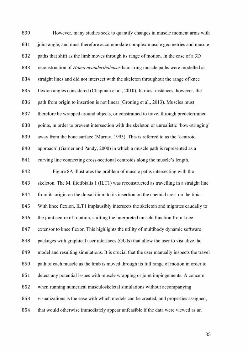
Figure 8A illustrates the problem of muscle paths intersecting with the 842
skeleton. The M. iliotibialis 1 (ILT1) was reconstructed as travelling in a straight line 843
from its origin on the dorsal ilium to its insertion on the cnemial crest on the tibia. 844
With knee flexion, ILT1 implausibly intersects the skeleton and migrates caudally to 845
the joint centre of rotation, shifting the interpreted muscle function from knee 846
extensor to knee flexor. This highlights the utility of multibody dynamic software 847
packages with graphical user interfaces (GUIs) that allow the user to visualize the 848
model and resulting simulations. It is crucial that the user manually inspects the travel 849
path of each muscle as the limb is moved through its full range of motion in order to 850
detect any potential issues with muscle wrapping or joint impingements. A concern 851
when running numerical musculoskeletal simulations without accompanying 852
visualizations is the ease with which models can be created, and properties assigned, 853
that would otherwise immediately appear unfeasible if the data were viewed as an 854
36
articulated skeleton. The process of visually inspecting muscle paths is time 855
consuming, but essential in order to achieve meaningful values for estimated moment 856
arms. In addition, when musculoskeletal models are to be used for MBDA, muscle 857
wrapping has been found to have a notable effect on force generation and the 858
inclusion of complex wrapping (as opposed to straight line origin-insertion) can bring 859
force estimates closer in line with in-vivo measured values (Gröning et al., 2013). 860
The specific options available for modifying the path of a muscle vary 861
between software packages (e.g., Gaitsym vs. OpenSim; see later discussion). 862
Regardless, a compromise will always exist between anatomical accuracy and muscle 863
paths that can be achieved feasibly within the constraints of the modeling software. 864
Two broad categories for describing changes in muscle path have been used: via 865
points and geometric shapes. 866
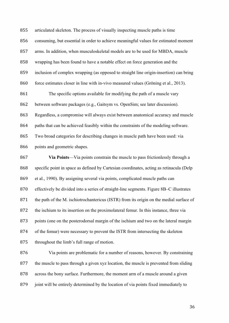
Via Points—Via points constrain the muscle to pass frictionlessly through a 867
specific point in space as defined by Cartesian coordinates, acting as retinacula (Delp 868
et al., 1990). By assigning several via points, complicated muscle paths can 869
effectively be divided into a series of straight-line segments. Figure 8B–C illustrates 870
the path of the M. ischiotrochantericus (ISTR) from its origin on the medial surface of 871
the ischium to its insertion on the proximolateral femur. In this instance, three via 872
points (one on the posterodorsal margin of the ischium and two on the lateral margin 873
of the femur) were necessary to prevent the ISTR from intersecting the skeleton 874
throughout the limb’s full range of motion. 875
Via points are problematic for a number of reasons, however. By constraining 876
the muscle to pass through a given xyz location, the muscle is prevented from sliding 877
across the bony surface. Furthermore, the moment arm of a muscle around a given 878
joint will be entirely determined by the location of via points fixed immediately to 879
37
either side of that joint. In other words, when via points are used to subdivide a 880
complicated muscle path into a series of straight line segments, the calculated moment 881
arm is that of the segment running across the joint in question, as opposed to a 882
reconstructed muscle running the entire anatomical distance from origin to insertion. 883
Osteological evidence of muscle scarring at origin and insertion sites may not, 884
therefore, contribute directly to the calculated moment arms. Instead, the positioning 885
of via points (which are byproducts of the modeling approach) can heavily influence 886
estimated moment arms. 887
When defining via points, it is necessary to specify the body segment to which 888
they will remain fixed during limb movement. In some instances, when a via point 889
replicates the behavior of a retinaculum located on the bony surface, for example, the 890
appropriate body segment is clear. In other scenarios, via points may be a fixed point 891
in space, some distance from the skeleton (Bates et al., 2012a:fig. 2G around the knee 892
joint of Lesothosaurus diagnosticus; Maidment et al., 2014a:fig. 2A–H around the 893
knee joint of several ornithischian dinosaurs). In the aforementioned studies, only 894
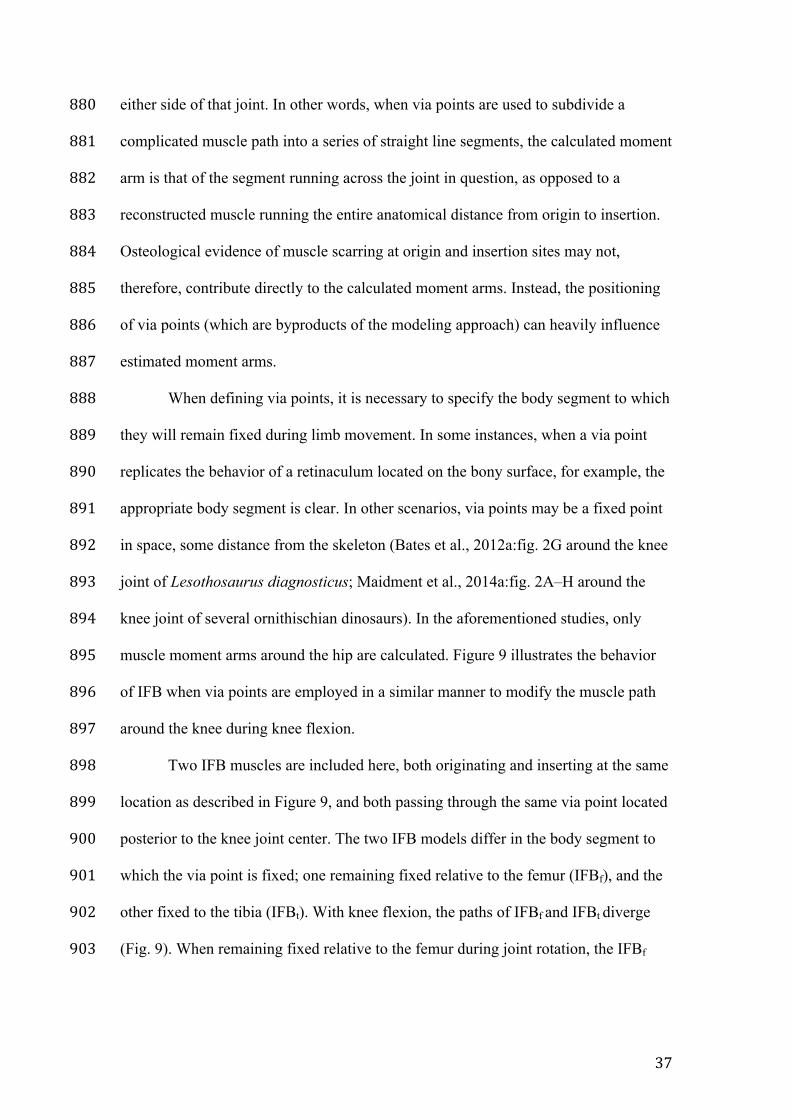
muscle moment arms around the hip are calculated. Figure 9 illustrates the behavior 895
of IFB when via points are employed in a similar manner to modify the muscle path 896
around the knee during knee flexion. 897
Two IFB muscles are included here, both originating and inserting at the same 898
location as described in Figure 9, and both passing through the same via point located 899
posterior to the knee joint center. The two IFB models differ in the body segment to 900
which the via point is fixed; one remaining fixed relative to the femur (IFBf), and the 901
other fixed to the tibia (IFBt). With knee flexion, the paths of IFBf and IFBt diverge 902
(Fig. 9). When remaining fixed relative to the femur during joint rotation, the IFBf 903
38
impinges on the posterior surface of the tibia, whilst the IFBt via point remains 904
stationary relative to the tibia and intersects the posterior surface of the femur. 905
The knee is a fairly straightforward case in which a clear biomechanical 906
argument could be made for the femur being the most appropriate body segment upon 907
which to attach the IFB via point, due to the likely location of the knee joint center 908
within the distal femoral condyles. In other cases, however, such as the neck, spine, 909
and ribcage, the decision as to which rigid body segment to kinematically link the via 910
point can be more ambiguous. Additionally, Sellers (2014) raises concerns regarding 911
the unrealistic behavior of via points at extreme values of joint rotation (as in Fig. 9), 912
and Garner and Pandy (2000) highlight the potential for discontinuities in moment 913
arms to occur when calculated across joints with more than one degree of freedom. 914
Geometric Shapes—As an alternative to via points, ‘obstacle set’ wrapping 915
(Garner and Pandy, 2000) seeks to represent anatomical features (such as bony 916
surfaces and underlying soft tissues) as simple geometric shapes including spheres, 917
cylinders, and toroids. Coordinates describing the surface contours of a joint may be 918
collected from CT/MRI, or via the use of a digitizing probe or microscribe on 919
cadaveric or dry skeletal material. Shapes may then be fitted to the bony landmarks 920
using an optimization process (Van der Helm et al., 1992) or via simple best-fitting of 921
circles as illustrated in Figure 7. 922
In contrast to via points, geometric shapes do not constrain a muscle to pass 923
through a specific xyz position in space, and instead allow the muscle to slide across 924
the surface of the object. Within the paleontological literature, cylinders are most 925
often deployed at the epiphyses of long bones to replicate the wrapping path of 926
muscles around the condyles (Hutchinson et al., 2005; Sellers et al., 2013). Typically, 927
the axis of a cylinder is constrained to pass through the joint center, with the long axis 928
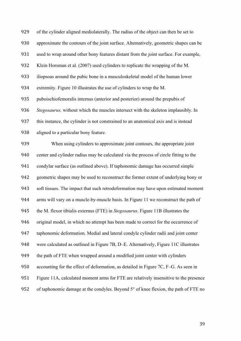
39
of the cylinder aligned mediolaterally. The radius of the object can then be set to 929
approximate the contours of the joint surface. Alternatively, geometric shapes can be 930
used to wrap around other bony features distant from the joint surface. For example, 931
Klein Horsman et al. (2007) used cylinders to replicate the wrapping of the M. 932
iliopsoas around the pubic bone in a musculoskeletal model of the human lower 933
extremity. Figure 10 illustrates the use of cylinders to wrap the M. 934
puboischiofemoralis internus (anterior and posterior) around the prepubis of 935
Stegosaurus, without which the muscles intersect with the skeleton implausibly. In 936
this instance, the cylinder is not constrained to an anatomical axis and is instead 937
aligned to a particular bony feature. 938
When using cylinders to approximate joint contours, the appropriate joint 939
center and cylinder radius may be calculated via the process of circle fitting to the 940
condylar surface (as outlined above). If taphonomic damage has occurred simple 941
geometric shapes may be used to reconstruct the former extent of underlying bony or 942
soft tissues. The impact that such retrodeformation may have upon estimated moment 943
arms will vary on a muscle-by-muscle basis. In Figure 11 we reconstruct the path of 944
the M. flexor tibialis externus (FTE) in Stegosaurus. Figure 11B illustrates the 945
original model, in which no attempt has been made to correct for the occurrence of 946
taphonomic deformation. Medial and lateral condyle cylinder radii and joint center 947
were calculated as outlined in Figure 7B, D–E. Alternatively, Figure 11C illustrates 948
the path of FTE when wrapped around a modified joint center with cylinders 949
accounting for the effect of deformation, as detailed in Figure 7C, F–G. As seen in 950
Figure 11A, calculated moment arms for FTE are relatively insensitive to the presence 951
of taphonomic damage at the condyles. Beyond 5° of knee flexion, the path of FTE no 952
40
longer wraps around the knee joint cylinder, and any discrepancy between models is 953
entirely due to a small shift in the joint center of rotation. 954
By contrast, when both muscle origin and insertion are located close to the 955
joint of interest, the muscle path may wrap around the fitted joint cylinder throughout 956
most of the joint’s range of motion. In Stegosaurus, the M. femorotibialis lateralis 957
(FMTL) originates on the lateral femoral shaft and attaches to the cnemial crest of the 958
tibia (Fig. 12B). As illustrated in Figure 12A, the moment arm of FMTL remains 959
constant through the entire range of motion of the knee as the path of the muscle 960
remains tightly wrapped around the knee joint cylinder. Furthermore, the value of the 961
moment arm is exactly equal to the radius of the object around which it is wrapped. 962
The phenomenon of constant muscle moment has been noted previously (Hutchinson 963
et al., 2005), highlighting the sensitivity of calculated moment arms to the estimated 964
size of the joint cylinders. In the case of the FMTL, accounting for deformation of the 965
femoral condyles results in a 28% increase in calculated moment arm throughout the 966
full range of motion at the knee. 967
Muscles modeled as wrapping around cylinders do appear to behave better (in 968
terms of avoiding skeletal impingement or unrealistic travel paths) than those 969
modeled with via points, particularly at extreme joint angles. A recent 970
musculoskeletal model of an extinct sauropod (Sellers et al., 2013) avoided the use of 971
via points altogether, opting instead for simplified geometric wrapping surfaces at the 972
joints. Regardless of the particular path modifier chosen, muscle function is often 973
assumed a priori when determining the path of a muscle. For example, when 974
wrapping a muscle around a cylinder, the direction of wrapping must be manually 975
assigned. In Figure 11B, the FTE has been explicitly modeled as travelling posterior 976
to the joint center and the associated wrapping cylinder, and its function has therefore 977
41
been constrained as a knee flexor. Therefore, whilst the general aim of many fossil 978
moment arm studies is to investigate muscle ‘function’, it must be recognized that the 979
broad function of many muscles (i.e., flexor vs. extensor) has already been 980
predetermined by virtue of the wrapping parameters chosen, and the EPB-based 981
myology upon which the model is based. 982
Finally, the layering of neighboring soft tissues such as muscle and tendon 983
may also be taken into consideration when defining individual muscle paths and 984
wrapping. Several studies calculating muscle moment arms have attempted to account 985
for this effect, with inferior muscles wrapping closer to joint surfaces than those lying 986
superior (Hutchinson et al., 2005). However, estimates of the likely thickness of 987
underlying muscle and tendon in fossils should be based on modern dissection data, of 988
which little has been published outside the clinical literature. Additionally, our current 989
models cannot account for shortening and thickening during contraction in 990
surrounding soft tissues and any potential effect that this may have upon calculated 991
moment arms. As such, it would be prudent to restrict modeling to individual muscle-992
tendon units in isolation from other neighboring soft tissues, in order to minimize 993
subjectivity and improve repeatability in model creation. 994
Biarticular Muscles—Several of the muscles included in the present model 995
are biarticular (i.e., span more than one joint). In common with most modern 996
cadaveric analyses of muscle moment arms (e.g., Channon et al., 2010), here we fix 997
the additional joint whilst manipulating the joint of interest through its range of 998
motion. Elsewhere, calculated muscle moment arms around the ankle have been 999
shown to be relatively insensitive to knee flexion (Holokwa and O’Neill, 2013). This 1000
suggests that the simplification of fixing additional joints may not unduly affect 1001
42
calculated moment arms around joints of interest, although further data from living 1002
taxa are required to confirm this. 1003
It must also be recognised that a biarticular muscle moment arm around one 1004
joint will be sensitive to the wrapping parameters of a neighbouring joint. Moment 1005
arms calculated around the knee, for example, are determined in part by the position 1006
of the hip wrapping surface, which is itself a function of the hip joint center location 1007
and wrapping geometry. Uncertainty in one joint can therefore permeate calculations 1008
of moment arms around neighbouring joints. In the case of biarticular muscles, 1009
sensitivity analyses may therefore benefit from incorporating uncertainty in both 1010
joints. 1011
1012
INTER- AND INTRASPECIFIC VARIATION IN MUSCLE MOMENT ARMS 1013
1014
Making Interspecific Comparisons between Fossil Taxa 1015
The foregoing discussion considers how the muscle moment arms of a single 1016
fossil individual may be calculated. Yet absolute values for the moment arms of a 1017
single individual are rarely of interest. Rather, comparative studies of numerous fossil 1018
species may be undertaken in order to quantify changes in muscle function within or 1019
between lineages, or higher order biomechanical variables assessed via forward 1020
dynamics approaches. When comparing a linear metric such as muscle moment arm 1021
between species, geometric similarity would predict absolutely larger animals to 1022
possess larger moment arm values. Therefore, in order to tease functional signals and 1023
overall body size signals apart, it is necessary to normalize muscle moment arm 1024
values. 1025
43
Osteometric scaling is a well-established practice in the human clinical 1026
literature (Sommer et al., 1982; Duda et al., 1996), and facilitates inter-specimen 1027
comparisons of muscle attachment sites. In comparative studies across modern taxa, 1028
limb muscle moment arms have been scaled by segment length (that is, moment arms 1029
calculated around the hip and knee are normalized to femur length, whilst those 1030
around the ankle are normalized to tibia length) (Payne et al., 2006; Crook et al., 1031
2010). This methodology has been applied to hind limb muscle moment arms 1032
calculated for comparative samples of dinosaur taxa (Bates et al., 2012b; Maidment et 1033
al., 2014a). Likewise the moment arms of jaw muscles acting around the 1034
temporomandibular joint have been normalized to mandible length in extant (Smith 1035
and Redford, 1990) and extinct (Vizcaíno and Iuliis, 2003) species. 1036
The motivation behind normalizing muscle moment arms by segment length is 1037
often to control for ‘body size’. By removing size-related signals from moment arm 1038
data, any functional signals of interest will become more apparent. When dividing 1039
muscle moment arms calculated around the hip by femoral length, for example, there 1040
is an assumption that femoral length is strongly correlated to overall ‘body size’ and 1041
does not itself contain a functional signal. Yet this is not the case. Several independent 1042
studies have found long bone length is often a less accurate predictor of body mass in 1043
modern vertebrates relative to cross-sectional properties (Damuth and MacFadden, 1044
1990; Campione and Evans, 2012), and segment length may contain a strong 1045
functional signal (Brassey et al., 2013). The elongated zeugopodium of modern 1046
wading birds is an extreme example. 1047
When attempting to remove ‘body size’ from an analysis of moment arms, a 1048
metric known to be highly correlated with body mass in modern species (such as 1049
stylopodial circumference or diameter: Campione and Evans, 2012; Brassey et al., 1050
44
2013) could be applied to normalize the data. Figure 13 illustrates the effect of 1051
normalizing moment arm values calculated for the M. caudofemoralis longus (CFL) 1052
around the hip in Stegosaurus and Kentrosaurus aethiopicus (see Maidment et al., 1053
2014a for model details), a smaller Late Jurassic stegosaurian. By normalizing CFL 1054
moment arms by linear dimensions of the femur, values for the two species are 1055
brought into closer agreement. Whilst the rank order of the two species does not 1056
change (Stegosaurus consistently has larger values for CFL moment arm than 1057
Kentrosaurus), the extent of the divergence between the two species does differ 1058
depending upon the normalizing metric applied. Peak CFL moment arms in 1059
Stegosaurus are 19% greater than those of Kentrosaurus when normalizing to femur 1060
length, compared to 38% when normalizing to anteroposterior diameter (Fig. 13B vs. 1061
Fig. 13D). 1062
However, this approach still requires a judgment to be made regarding which 1063
skeletal metric should be preferred. Alternatively, an osteometric scaling approach 1064
based on procrustes superimposition of skeletal elements could be applied to remove 1065
the effects of translation, rotation, and scaling, and quantify the impact of changes in 1066
bone geometry and attachment sites on muscle moment arms. A geometric mean of 1067
several skeletal variables could also be used. In reality, however, the occurrence of 1068
taphonomic damage and weathering may preclude the application of a particular 1069
metric to a given group of fossils, and normalization of a dataset should be considered 1070
on a case-by-case basis. To facilitate future comparisons, the process of moment arm 1071
normalization should be explicitly described in the methodology. In addition, the 1072
potential for the normalization process to change the rank order of calculated moment 1073
arms within the sample should be recognized. 1074
1075
45
Intraspecific Variation in Moment Arms 1076
In addition to interspecific differences, evidence from the clinical literature 1077
suggests that within-species variation in muscle moment arms can also be 1078
considerable. In human adults, the relationship between moment arm and joint angle 1079
typically describes an overall similar curve between individuals, whilst possessing 1080
different absolute values (in the knee: Herzog and Read, 1993; and elbow: Murray et 1081
al., 2002). Much of the difference in absolute values is attributed to intraspecific 1082
variation in total body size. Yet, despite performing osteometric scaling on the basis 1083
of markers and reference points, Duda et al. (1996) still found considerable 1084
differences in the position of femoral muscle attachment centroids across a sample of 1085
humans, resulting in moment arm standard deviations of up to 65% of the mean in 1086
some muscles. Therefore, even when accounting for changes in overall body size, 1087
intraspecific variation in muscle attachment sites is likely to be present in calculated 1088
muscle moment arms. 1089
Outside of humans, few data exist for extant taxa regarding within-species 1090
variation in attachment sites and muscle moment arms (but see Smith et al., 2007). 1091
Within the body of available data, confounding epigenetic factors confuse matters 1092
further, including adaptations in response to exercise regimes in captive zoo animals 1093
and domesticated species. Ontogeny also has an impact on moment arms, with 1094
muscles shifting their location relative to one another, and to the joint they act around, 1095
with age (Carrier, 1983; Young, 2005; Singleton, 2015). The moment arms calculated 1096
herein for a subadult Stegosaurus specimen, for example, may not be directly 1097
comparable to those of a mature individual of the same species, or to adult specimens 1098
of closely related taxa. 1099
46
Intraspecific variation is rarely considered in paleontological musculoskeletal 1100
reconstructions, however, due either to lack of specimens or constraints associated 1101
with the time-consuming process of model creation. Yet given the substantial 1102
inconsistency in muscle attachment positions (and hence moment arms) in modern 1103
humans, further research into the relative magnitudes of inter- and intraspecific 1104
variability in moment arms across modern comparative samples may be necessary. If 1105
between-species variation in moment arms is found to dwarf that within-species, then 1106
we may have more confidence in attributing patterns in calculated moment arms of 1107
fossil species to functional shifts within lineages. 1108
1109
VERIFICATION AND VALIDATION OF MUSCLE MOMENT ARM MODELS 1110
1111
The discussion provided above outlines the process of generating 1112
musculoskeletal models for fossil taxa from which muscle moment arms may then be 1113
calculated. Yet, in addition to creating an accurate 3D representation of a fossil 1114
skeleton and associated musculature, it is important to verify and validate model 1115
results. In their review of computational modeling of the neuromusculoskeletal 1116
system, Hicks et al. (2014) considered the best practices for verifying and validating 1117
biomechanical models of muscles and movement. These authors emphasized the 1118
difference between verifying MDBA software (‘are we solving the equations 1119
correctly?’) and validating model results (‘are we solving the correct equations?’). 1120
1121
Verification 1122
For users, the process of verifying whether or not MBDA software is 1123
implementing algorithms correctly has been mostly completed. When employing 1124
47
well-established software modules (either commercial or open source), most source 1125
code has been independently verified by an extensive user community. Commercial 1126
packages such as SIMM (Delp et al., 1990), Adams (MSC Software Corp.), and 1127
AnyBody (AnyBody Technology) have already been successfully applied to a wide 1128
spectrum of biomechanical problems, including non-human extant taxa (frog: Kargo 1129
and Rome, 2002; horse,:Brown et al., 2003; tuatara: Curtis et al., 2010; rat: Wehner et 1130
al., 2010; rabbit: Watson et al., 2014; pigs: Basafa et al., 2014) and occasionally 1131
fossils (Hutchinson et al., 2005; Snively et al., 2013). 1132
The above-mentioned software packages do not, however, provide full access 1133
to the source code. OpenSim (Delp et al., 2007) and GaitSym (Sellers, 2014) are 1134
open-source alternatives. OpenSim uses SimBody as its physics engine, and has been 1135
applied in numerous non-human studies, including the macaque forelimb 1136
(Schaffelhofer et al., 2015), and chimpanzee (O’Neill et al., 2013), sheep (Lerner et 1137
al., 2015), and rat (Johnson, 2009) hind limbs. Likewise, Gaitsym is open-source and 1138
uses the Open Dynamics Engine (ODE) physics library to perform most rigid body 1139
dynamics calculations. Gaitsym (and its precursors) have been applied to MBDA of 1140
both extant (human: Sellers et al., 2010; chimpanzee: Sellers et al., 2013) and extinct 1141
(hominoid: Nagano et al., 2005; Sellers et al., 2005; dinosaur: Sellers and Manning, 1142
2007; Bates et al., 2012a, b; Maidment et al., 2014a) taxa. 1143
A recent study comparing the results of MDBA run using various physics 1144
engines (including ODE, Bullet, and Simbody) reassuringly found only minor 1145
differences in performance when applied to a simple walking task (Peters and Hsu, 1146
2014). However, as far as we are aware, a straightforward comparison of moment arm 1147
values calculated for equivalent musculoskeletal models across different MBDA 1148
software packages has yet to be attempted. Such a comparison could potentially prove 1149
48
interesting, as current MBDA packages differ considerably in the muscle wrapping 1150
parameters available to users. For example, while muscles may be modelled as 1151
wrapping around toroids in OpenSim, GaitSym only allows muscle wrapping around 1152
cylinders. Models created in one package may not, therefore, be directly imported and 1153
verified in another. Finally, 3D moment arm calculations are essentially simple 1154
trigonometry problems, and may be verified using back-of-the-envelope calculations. 1155
Moment arm values calculated from detailed 3D musculoskeletal models employing 1156
complex muscle-wrapping should therefore be verified using this simplified approach 1157
to ensure that both techniques converge on similar results. 1158
1159
Validation 1160
Validating the outputs of musculoskeletal models for extinct species is 1161
obviously impossible. Therefore, for a biomechanical reconstruction technique to be 1162
considered reliable when employed in paleontology, its validity can only be 1163
approximated by applying it to relevant extant taxa (Hutchinson, 2011). When 1164
attempting to validate techniques for calculating muscle moment arms and inferring 1165
muscle function, we can ask the following questions related to modern taxa: 1) do 1166
muscle moment arms calculated using musculoskeletal models agree with 1167
experimental values?; and 2) do calculated muscle moment arms contain an obvious 1168
functional signal? 1169
How do Muscle Moment Arms Calculated using Musculoskeletal Models 1170
Compare with those Measured Experimentally?—Within clinical biomechanics, 1171
there exists a substantial body of research comparing moment arm estimates derived 1172
from mathematical models to those estimated experimentally, due to the considerable 1173
advantages associated with avoiding invasive procedures or dissections. Numerous 1174
49
studies have found human moment arm estimates calculated from 3D computer 1175
models to fall consistently within the range of empirical data, for both ‘simple’ hinge 1176
joints such as the elbow (Murray et al., 1998) and more 'complex' joints including the 1177
knee (Arnold et al., 2000; Gatti et al., 2007). In non-human studies, a similar pattern 1178
is present in the hip and knee joints of frogs (Kargo and Rome, 2002) and 1179
chimpanzees (O’Neill et al., 2013), and the distal forelimb of horses (Brown et al., 1180
2003), in which moment arms estimated from 3D musculoskeletal models have been 1181
found to be well-matched to those calculated experimentally, typically via the tendon-1182
travel method. In some situations, it has been suggested that 3D modeling may be 1183
preferable to the tendon-travel method, due to the potential for muscle lines-of-action 1184
to be altered through the process of excising surrounding soft tissues during dissection 1185
(Hutchinson et al., 2015). Thus, the broad agreement between experimental and 1186
model results in extant taxa supports musculoskeletal modeling as a valid approach to 1187
calculating muscle moment arms in extinct taxa assuming a reliable myological 1188
reconstruction is available. The modern studies cited above rely upon detailed 1189
dissection data to inform the model-making process, something that is obviously 1190
unobtainable for fossil taxa. Whilst the agreement between techniques gives us 1191
confidence in 3D models as a means of calculating moment arms, musculoskeletal 1192
modeling is still subject to the phenomenon of ‘Garbage In, Garbage Out’ (GIGO), 1193
and the value of the moment arms output is directly a function of the quality of the 1194
myology upon which the model is based. 1195
Functional Signals in the Muscle Moment Arms of Extant Species—For a 1196
given property to be informative when applied to the fossil record, it must be first 1197
understood in extant taxa. In the case of muscle moment arms, values derived from 1198
fossil species are rarely of interest in and of themselves, but are instead used as a 1199
50
proxy for musculoskeletal function. Yet, as highlighted by Gans and De Vree 1200
(1987:76): “It remains necessary to check whether sites at which muscles are placed 1201
differ interspecifically and whether the functional […] implications of these 1202
differences match possible differences in role. If they do not, it is likely that the 1203
character state reflects phylogeny more than function”. Whilst dissection-based 1204
myological descriptions have a rich history in the field of modern comparative 1205
anatomy, and muscle moment arms are increasingly reported, the relationship 1206
between gross muscle architecture and muscle function across broad comparative 1207
datasets remains less than clear. 1208
In some instances, the calculated muscle moment arms of extant taxa may 1209
contain a functional signal. Rat hind limb muscle moment arms have been found to 1210
vary considerably throughout the physiological limb range of motion, yet peak and 1211
remain relatively constant within the range of motion domain occupied during 1212
locomotion (Johnson et al., 2008), implying moment arms may be indicative of 1213
dynamic limb posture. A caveat is that most rodent locomotion studies, such as 1214
Johnson et al. (2008), rely upon skin markers for their kinematics, which may poorly 1215
reflect the behavior of the underlying joints (Bauman and Chang, 2010). Likewise, the 1216
hardness of food items has been shown to influence mandible shape, and hence the 1217
mechanical advantage (ratio of the inlever and outlever) of several masticatory 1218
muscles in laboratory mice (Anderson et al., 2014), implying jaw muscle moment 1219
arms may correlate to dietary preference. Yet elsewhere, the moment arms of ostrich 1220
hind limb antigravity muscles calculated via 3D modeling were not found to peak at 1221
angles corresponding to mid-stance of walking and running during gait trials 1222
(Hutchinson et al., 2015), suggesting that there may not be a straightforward 1223
relationship between limb posture during stance phase and moment arms. 1224
51
Additionally, the functional characteristics of muscle architecture can be 1225
studied on three levels (Gans and De Vree, 1987): 1) muscles within the organism; 2) 1226
fibers within the muscle; and 3) sarcomeres within the fibers. While paleontologists 1227
are restricted to the reconstruction of gross myology, there is mounting evidence that 1228
organisms primarily adapt their musculature to prevailing biomechanical conditions 1229
by changing intrinsic muscle properties. An increase in muscle moments within the 1230
limbs of sprinting racehorses relative to endurance horses has been attributed to 1231
increased muscle volume and physiological cross-sectional area rather than moment 1232
arm, for example (Crook et al., 2010). Similarly, modern gibbons have been found to 1233
employ a variety of compromises between fiber length and moment arm in order to 1234
achieve diverse biomechanical objectives (torque vs. control) within the hind limb 1235
(Channon et al., 2010), and adaptation to different feeding strategies in feline jaw 1236
muscles has been identified primarily in muscle fiber length (Hartstone-Rose et al., 1237
2012). 1238
In reality, the potential for a muscle to produce a moment is a function of both 1239
its moment arm and its ability to generate force, which is itself influenced by muscle 1240
size and internal organization. It may, therefore, be the ‘totality’ of the muscle 1241
architecture that is under the influence of selection (Gans and De Vree, 1987), without 1242
a well-defined relationship between one particular variable (such as moment arm) and 1243
a given function. Until a correlation between moment arm and function can be 1244
broadly identified across a range of modern taxa, the interpretation of moment arms 1245
calculated for extinct taxa should be approached with caution (Maidment et al., 1246
2014a). 1247
1248
SUMMARY 1249
52
1250
In the preceding discussion, we outline the process of generating a 1251
musculoskeletal model for the purpose of muscle moment arm calculations in fossil 1252
specimens. In doing so, we highlight the model parameters to which calculated 1253
moment arms are particularly sensitive or robust. As a field, paleontology is 1254
increasingly engaging with methods of specimen digitization and musculoskeletal 1255
simulation and it is tempting to create ever more detailed and sophisticated models of 1256
extinct species. It is crucial, however, that our desire to generate ‘realistic’ models of 1257
fossil taxa does not outstrip the extent to which we may make reasonable inferences 1258
regarding the individual, and that we avoid becoming so ‘seduced’ by a technique that 1259
we might end up with models we no longer understand (Anderson et al., 2011). 1260
It is beneficial, therefore, to refer back to the hierarchy of biomechanical 1261
questions outlined in the Introduction, to which muscle moment arm analyses are 1262
frequently applied. When utilizing musculoskeletal models to predict the role of an 1263
individual muscle around a joint (e.g., flexor vs. extensor), we might reasonably have 1264
confidence in the interpretation of muscle moment arms, as uncertainty in factors such 1265
as wrapping cylinder radii or joint center location are unlikely to change the 1266
fundamental action of a muscle. Variation in such parameters will impact upon 1267
moment arm magnitudes, however, and thus may change the rank order of individuals 1268
within a broad interspecific sample and fundamentally affect the interpretation of a 1269
dataset. Consequently, it is currently unclear whether moment arm analyses may be 1270
appropriately applied to test broader evolutionary hypotheses regarding changes in 1271
biomechanical function between lineages. Furthermore, the functional signal 1272
contained within the moment arms of extant species can often be contradictory. Until 1273
the methodology outlined above for the calculation of muscle moment arms can be 1274
53
shown to reliably illuminate aspects of biomechanical function in extant taxa, 1275
paleontological studies of moment arms are being held at an “impasse” (Hutchinson et 1276
al., 2015:1). 1277
Looking to the future, it is worth considering how we wish to use muscle 1278
moment arm data when applied to the fossil record. Is it important to understand the 1279
mechanical signal contained within muscle moment arm data? Or can muscle moment 1280
arms be used in a purely statistical sense, as a correlate for another parameter of 1281
interest? And, if the latter is the case, are complex models and simulations required to 1282
capture this data? 3D musculoskeletal models are still labor intensive, and their usage 1283
necessarily restricts sample sizes. If the aim of analysis is simply to ‘bin’ extinct 1284
species into disparate categories, such as ‘cursorial vs. digging’, or ‘upright vs. 1285
sprawling’, discriminant analyses on modern datasets of 2D moment arms may be 1286
more appropriate. Such analyses may be based on straightforward linear osteological 1287
measurements (Fujiwara and Hutchinson, 2012), facilitating the collection of large 1288
modern datasets without the need for extensive dissections or complex 3D muscle 1289
wrapping paths in our models. Statistical analyses such as these would also allow 1290
confidence limits to be ascribed to any predictions of potential function. 1291
Alternatively, if 3D musculoskeletal models are favored, muscle moment arms 1292
may simply be a ‘means to an end’ for calculating other meaningful biomechanical 1293
parameters using powerful tools such as FEA, inverse- or forward MBDA. In this 1294
instance, muscle moment arms do still function as statistical correlates for the 1295
maximum moment-generating capacity of muscles. Such analyses can provide 1296
important insights into the functioning of muscle groups during locomotion, and may 1297
even generate gaits de novo. These studies do, however, require additional 1298
assumptions regarding the physiological cross-sectional area of muscles, fiber and 1299
54
tendon lengths, and muscle activation patterns. Fundamentally, the quality of the 1300
fossil and the existence of modern analogues with associated anatomical data should 1301
dictate the complexity of the question being addressed, and by virtue the detail 1302
required within the model. 1303
Moving forward, it is also essential that moment arm analyses pass the 1304
fundamental test of reproducibility. Previous paleontological studies have claimed 1305
that comparisons between musculoskeletal models may be easily made, as the 3D 1306
moment arm technique is quantifiable and repeatable (Maidment et al., 2014a). 1307
However, the extent to which moment arm calculations are reproducible has rarely 1308
been confirmed (although see Bates et al., 2012a). In addition to inter-observer 1309
variation in the interpretation and implementation of a given myology, variation in 1310
wrapping parameters between MBDA software packages makes repetition of results 1311
across studies challenging. Future studies should seek to standardize the reporting of 1312
musculoskeletal model parameters, in order to facilitate data sharing and model 1313
reproducibility. 1314
1315
ACKNOWLEDGMENTS 1316
1317
We are grateful for the insightful comments of Matthew Bonnan, John Whitlock, and 1318
one anonymous reviewer. The authors would also like to thank Bill Sellers for useful 1319
discussions and for his efforts in creating and maintaining GaitSym. We also express 1320
our sincere thanks to Jeremy Herrmann and the 69 other donors who made acquisition 1321
of the Stegosaurus specimen possible. 1322
1323
LITERATURE CITED 1324
55
1325
Ackland, D. C., D. Pak, M. Richardson, and M. G. Pandy. 2008. Moment arms of the 1326
muscles crossing the anatomical shoulder. Journal of Anatomy 213:383–390. 1327
Alexander, R. M. N. 1989. Dynamics of dinosaurs and other extinct giants. 1328
Cambridge University Press, Cambridge, 167pp. 1329
Alexander, R. M. N. 2003. Principles of Animal Locomotion. Princeton University 1330
Press, New Jersey, 384 pp. 1331
An, K. N., K. Takahashi, T. P. Harrigan, and E. Y. Chao. 1984. Determination of 1332
muscle orientations and moment arms. Journal of Biomechanical Engineering 1333
106:280–282. 1334
Anderson, P. S. L., and M. W. Westneat. 2009. A biomechanical model of feeding 1335
kinematics for Dunkleosteus terrelli (Arthrodira, Placodermi). Journal of 1336
Paleontology 35:251–269. 1337
Anderson, P. S. L., S. Renaud, and E. J. Rayfield. 2014. Adaptive plasticity in the 1338
mouse mandible. BMC Evolutionary Biology 14:85. DOI: 10.1186/1471-2148-1339
14-85. 1340
Anderson, P. S. L., J. A. Bright, P. G. Gill, C. Palmer, and E. J. Rayfield. 2011. 1341
Models in palaeontological functional analysis. Biology Letters 23:119–122. 1342
Arnold, A. S., S. Salinas, D. J. Asakawa, and S. L. Delp. 2000. Accuracy of muscle 1343
moment arms estimated from MRI-based musculoskeletal models of the lower 1344
extremity. Computed Aided Surgery 119:108–119. 1345
Arnold, E. M., S. R. Ward, R. L. Lieber, and S. L. Delp. 2010. A model of the lower 1346
limb for analysis of human movement. Annals of Biomedical Engineering 1347
38:269–279. 1348
56
Astley, H. C., and T. J. Roberts. 2012. Evidence for a vertebrate catapult: elastic 1349
energy storage in the plantaris tendon during frog jumping. Biology Letters 1350
8:386–389. 1351
Baerlocher, P., and R. Boulic. 2001. Parametrization and range of motion of the ball-1352
and-socket joint. IFIP Advances in Information and Communication 1353
Technology 68:180–190. 1354
Bargo, M. S. 2001. The ground sloth Megatherium americanum: Skull shape, bite 1355
forces, and diet. Acta Palaeontologica Polonica 46:173–192. 1356
Basafa, E., R. J. Murphy, C. R. Gordon, and M. Armand. 2014. Modeling the 1357
biomechanics of swine mastication - An inverse dynamics approach. Journal of 1358
Biomechanics 47:2626–2632. 1359
Bates, K. T., and E. R. Schachner. 2011. Disparity and convergence in bipedal 1360
archosaur locomotion. Journal of The Royal Society Interface 9:1339–1353. 1361
Bates, K. T., and P. L. Falkingham. 2012. Estimating maximum bite performance in 1362
Tyrannosaurus rex using multi-body dynamics. Biology Letters 8:660–664. 1363
Bates, K. T., R. B. J. Benson, and P. L. Falkingham. 2012b. A computational analysis 1364
of locomotor anatomy and body mass evolution in Allosauroidea (Dinosauria: 1365
Theropoda). Paleobiology 38:486–507. 1366
Bates, K. T., S. C. R. Maidment, V. Allen, and P. M. Barrett. 2012a. Computational 1367
modelling of locomotor muscle moment arms in the basal dinosaur 1368
Lesothosaurus diagnosticus: Assessing convergence between birds and basal 1369
ornithischians. Journal of Anatomy 220:212–232. 1370
Bauman, J. M., and Y. H. Chang. 2010. High speed x-ray video demonstrates 1371
significant skin movement errors with standard optical kinematics during rat 1372
locomotion. Journal of Neuroscience Methods 30:18–24. 1373
57
Bolsterlee B, H. E. Veeger , and F. C. van der Helm. 2014. Modelling clavicular and 1374
scapular kinematics: From measurement to simulation. Medical and Biological 1375
Engineering and Computing 52:283–291. 1376
Bonnan, M. F., J. L. Sandrik, T. Nishiwaki, D. R. Wilhite, R. M. Elsey, and C. 1377
Vittore. 2010. Calcified cartilage shape in archosaur long bones reflects 1378
overlying joint shape in stress-bearing elements: Implications for nonavian 1379
dinosaur locomotion. Anatomical Record 293:2044–55. 1380
Bonnan, M. F., J. Shulman, R. Varadharajan, C. Gilbert, M. Wilkes, A. Horner and E. 1381
Brainerd. 2016. Forelimb kinematics of rats using XROMM, with implications 1382
for small eutharians and their fossil relative. 11(3): e0149377. 1383
Brassey, C. A. In press. Body mass estimation in paleontology: a review of 1384
volumetric techniques. Journal of Paleontology. 1385
Brassey, C. A, S. C. R. Maidment, and P. M. Barrett. 2015. Body mass estimates of 1386
an exceptionally complete Stegosaurus (Ornithischia: Thyreophora): comparing 1387
volumetric and linear bivariate mass estimation methods. Biology Letters 1388
11:20140984. DOI: 10.1098/rsbl.2014.0984. 1389
Brassey, C. A., A. C. Kitchener, P. J. Withers, P. L. Manning, and W. I. Sellers. 2013. 1390
The role of cross-sectional geometry, curvature, and limb posture in maintaining 1391
equal safety factors: A computed tomography study. The Anatomical Record 1392
296:395–413. 1393
Bright, J. A. 2014. A review of paleontological finite element models and their 1394
validity. Journal of Paleontology 88:760–769. 1395
Brown, N. A. T., M. G. Pandy, C. E. Kawcak, and C. W. Mcllwraith. 2003. Force- 1396
and moment-generating capacities of muscles in the distal forelimb of the horse. 1397
Journal of Anatomy 203:101–113. 1398
58
Bryant, H. N., and K. L. Seymour. 1990. Observations and comments on the 1399
reliability of muscle reconstruction in fossil vertebrates. Journal of Morphology 1400
117:109–117. 1401
Bucher, I. 2004. Circle fit. Available at 1402
http://uk.mathworks.com/matlabcentral/fileexchange/5557-circle-1403
fit/content/circfit.m (accessed 7th September 2016). 1404
Campione, N. E., and D. C. Evans. 2012. A universal scaling relationship between 1405
body mass and proximal limb bone dimensions in quadrupedal terrestrial 1406
tetrapods. BMC Biology 10:60. DOI: 10.1186/1741-7007-10-60. 1407
Carrier, D. R. 1983. Postnatal ontogeny of the musculo-skeletal system in the black-1408
tailed jack rabbit (Lepus californicus). Journal of Zoology 201:27–55. 1409
Cassini, G. H., and S. F. Vizcaíno. 2012. An approach to the biomechanics of the 1410
masticatory apparatus of early Miocene (Santacrucian age) South American 1411
ungulates (Astrapotheria, Litopterna, and Notoungulata): Moment arm 1412
estimation based on 3D landmarks. Journal of Mammalian Evolution 19:9–25. 1413
Chadwick, E. K., D. Blana, A. J. van den Bogert, and R. F. Kirsch. 2009. A real-time, 1414
3-D musculoskeletal model for dynamic simulation of arm movements. IEEE 1415
Transactions on Biomedical Engineering 56:941–948. 1416
Channon, A. J., R. H. Crompton, M. M. Günther, and E. E. Vereecke. 2010. Muscle 1417
moment arms of the gibbon hind limb: implications for hylobatid locomotion. 1418
Journal of Anatomy 216:446–462. 1419
Chapman, T., F. Moiseev, V. Sholukha, S. Louryan, M. Rooze, P. Semal, and S. Van 1420
Sint Jan. 2010. Virtual reconstruction of the Neandertal lower limbs with an 1421
estimation of hamstring muscle moment arms. Comptes Rendus Palevol 9:445–1422
454. 1423
59
Chinsamy-Turan, A. 2005. The Microstructure of Dinosaur Bone: Deciphering 1424
Biology with Fine-Scale Techniques. Johns Hopkins University Press, 1425
Baltimore, 216 pp. 1426
Cobley, M. J., E. J. Rayfield, and P. M. Barrett. 2013. Inter-vertebral flexibility of the 1427
ostrich neck: Implications for estimating saurpod neck flexibility. PLoS ONE 1428
8:e72187. DOI:10.1371/journal.pone.0072187. 1429
Costa, F. R., O. Rocha-Barbosa, and A. W. A. Kellner. 2013. A biomechanical 1430
approach on the optimal stance of Anhanguera piscator (Pterodactyloidea) and 1431
its implications for pterosaur gait on land. Historical Biology 26:582–590. 1432
Crook, T. C., S. E. Cruickshank, C. M. McGowan, N. Stubbs, A. M. Wilson, E. 1433
Hodson-Tole, and R. C. Payne. 2010. A comparison of the moment arms of 1434
pelvic limb muscles in horses bred for acceleration (Quarter Horse) and 1435
endurance (Arab). Journal of Anatomy 217:26–37. 1436
Cuff, A. R., and E. J. Rayfield. 2015. Retrodeformation and muscular reconstruction 1437
of ornithomimosaurian dinosaur crania. PeerJ 3:e1093. DOI: 1438
10.7717/peerj.1093. 1439
Curtis, N., M. E. H. Jones, A. K. Lappin, P O'Higgins, S. E. Evans, and M. J. Fagan. 1440
2010. Comparison between in vivo and theoretical bite performance: using 1441
multi-body modelling to predict muscle and bite forces in a reptile skull. Journal 1442
of Biomechanics 43:2804–2809. 1443
D’Anastasio, R., S. Wroe, C. Tuniz, L. Mancini, D. T. Cesana, D. Dreossi, M. 1444
Ravichandiran, M. Attard, W. C. H. Parr, A. Agur, and L. Capasso. 2013. 1445
Micro-biomechanics of the Kebara 2 hyoid and its implications for speech in 1446
Neanderthals. PLoS ONE 8:e82261. DOI: 10.1371/journal.pone.0082261. 1447
60
Damuth, J., and B. J. MacFadden. 1990. Body Size in Mammalian Paleobiology: 1448
Estimation and Biological Implications. Cambridge University Press, 1449
Cambridge, 412 pp. 1450
Delp, S. L., and W. Maloney. 1993. Effects of hip center location on the moment-1451
generating capacity of the muscles. Journal of Biomechanics 26:485–499. 1452
Delp, S. L., J. P. Loan, M. G. Hoy, F. E. Zajac, E. L. Topp, and J. M. Rosen. 1990. 1453
An interactive graphics-based model of the lower extremity to study 1454
orthopaedic surgical procedures. IEEE Transactions on Biomedical Engineering 1455
37:757–767. 1456
Delp, S. L., F. C. Anderson, A. S. Arnold, P. Loan, A. Habib, C. T. John, E. 1457
Guendelman, and D. G. Thelen. 2007. OpenSim: Open-source software to 1458
create and analyze dynamic simulations of movement. IEEE Transactions on 1459
Biomedical Engineering 54:1940–1950. 1460
DeMar, R., and H. R. Barghusen. 1972. Mechanics and the evolution of the synapsid 1461
jaw. Evolution 26:622–637. 1462
Demes, B. 1988. Bite force, diet, and cranial morphology of fossil hominids. Journal 1463
of Human Evolution 17:657–670. 1464
Dilkes, D. W., J. R. Hutchinson, C. M. Holliday, and L. M. Witmer. 2012. 1465
Reconstructing the musculature of dinosaurs; pp. 151–190 in M. K. Brett-1466
Surman, T. R. Holtz Jr., and J. O. Farlow (Eds.) The Complete Dinosaur. 1467
Indiana University Press, Bloomington. 1468
Domalain, M., A. Bertin, and G. Daver. In press. Was Australopithecus afarensis able 1469
to make the Lomekwian stone tools? Towards a realistic biomechanical 1470
simulation of hand force capacity in fossil hominins and new insights on the 1471
role of the fifth digit. Comptes Rendus Palevol. 1472
61
Duda, G. N., D. Brand, S. Freitag, W. Lierse, and E. Schneider. 1996. Variability of 1473
femoral muscle attachments. Journal of Biomechanics 29:1185–1190. 1474
Eckhoff, D. G., J. M. Bach, V. M. Spitzer, K. D. Reinig, M. M. Bagur, T. H. Baldini, 1475
D. Rubinstein, and S. Humphries. 2003. Three-dimensional morphology and 1476
kinematics of the distal part of the femur viewed in virtual reality, Part II. 1477
Journal Of Bone And Joint Surgery 85:97–104. 1478
Emerson, S. B., and L. Radinsky. 1980. Functional analysis of sabertooth cranial 1479
morphology. Paleobiology 6:295–312. 1480
Falkingham, P. L. 2012. Acquisition of high resolution three-dimensional models 1481
using free, open-source, photogrammetric software. Palaeontologia Electronica 1482
15:1.1T. http://palaeo-electronica.org/content/issue1-2012technical-articles/92-1483
3d-photogrammetry 1484
Falkingham, P. L. 2014. Interpreting ecology and behaviour from the vertebrate fossil 1485
track record. Journal of Zoology 292:222–228. 1486
Favre, P., M. D. Loeb, N. Helmy, and C. Gerber. 2008. Latissimus dorsi transfer to 1487
restore external rotation with reverse shoulder arthroplasty: A Biomechanical 1488
Study. Journal of Shoulder and Elbow Surgery 17:650–658. 1489
Fisher, H. I. 1945. Locomotion in the Fossil Vulture Teratornis. American Midland 1490
Naturalist 33:725–742. 1491
Fox, R. C. 1964. The adductor muscles of the jaw in some primitive reptiles. 1492
University of Kansas Public Museum of Natural History 12:657–680. 1493
Fujiwara, S., and J. R. Hutchinson. 2012. Elbow joint adductor moment arm as an 1494
indicator of forelimb posture in extinct quadrupedal tetrapods. Proceedings of 1495
the Royal Society B: Biological Sciences 279:2561–2570. 1496
62
Gans, C., and F. De Vree. 1987. Functional bases for fiber length and angulation in 1497
muscle. Journal of Morphology 192:63–85. 1498
Garner, B. A., and M. G. Pandy. 2000. The obstacle-set method for representing 1499
muscle paths in musculoskeletal models. Computer Methods in Biomechanics 1500
and Biomedical Engineering 3:1–30. 1501
Gatti, C. J., C. Dickerson, E. K. Chadwick, A. G. Mell, and R. E. Hughes. 2007. 1502
Comparison of model-predicted and measured moment arms for the rotator cuff 1503
muscles. Clinical Biomechanics 22:639–644. 1504
Gill, P. G., M. A. Purnell, N. Crumpton, K. Robson Brown, N. J. Gostling, M. 1505
Stampanoni, and E. J. Rayfield. 2014. Dietary specializations and diversity in 1506
feeding ecology of the earliest stem mammals. Nature 512:303–305. 1507
Gregory, R. D. 2006. Classical Mechanics. Cambridge University Press, Cambridge, 1508
608 pp. 1509
Gröning, F., M. E. H. Jones, N. Curtis, A. Herrel, P. O'Higgins, S. E. Evans, and M. J. 1510
Fagan. 2013. The importance of accurate muscle modelling for biomechanical 1511
analyses: a case study with a lizard skull. Journal of The Royal Society Interface 1512
10:20130216.DOI: 10.1098/rsif.2013.0216. 1513
Hartstone-Rose, A., J. M. G. Perry, and C. J. Morrow. 2012. Bite force estimation and 1514
the fiber architecture of felid masticatory muscles. Anatomical Record 1515
295:1336–1351. 1516
Hatala, K. G., R. G. Wunderlich, H. L. Dingwall, and B. G. Richmond. 2016. 1517
Interpreting locomotor biomechanics from the morphology of human footprints. 1518
Journal of Human Evolution 90:38–48. 1519
Hieronymus, T. L. 2006. Quantitative microanatomy of jaw muscle attachment in 1520
extant diapsids. Journal of Morphology 267:954–967. 1521
63
Henderson, D. M. 2006. Burly gaits: Centers of mass, stability, and the trackways of 1522
sauropod dinosaurs. Journal of Vertebrate Paleontology 26:907–921. 1523
Herzog, W., and L. J. Read. 1993. Lines of action and moment arms of the major 1524
force-carrying structures crossing the human knee joint. Journal of Anatomy 1525
182:213–230. 1526
Hicks, J. L., T. K. Uchida, A. Seth, A. Rajagopal, and S. L. Delp. 2014. Is my model 1527
good enough? Best practices for verification and validation of musculoskeletal 1528
models and simulations of human movement. Journal of Biomechanical 1529
Engineering 137:020905. DOI: 10.1115/1.4029304. 1530
Holliday, C. M. 2009. New insights into dinosaur jaw muscle anatomy. Anatomical 1531
Record 292:1246–1265. 1532
Holliday, C. M., R. C. Ridgley, J. C. Sedlmayr, and L. M. Witmer. 2010. 1533
Cartilaginous epiphyses in extant archosaurs and their implications for 1534
reconstructing limb function in dinosaurs. PLoS ONE 5:e13120. DOI: 1535
10.1371/journal.pone.0013120. 1536
Holokwa, N. B., and M. C. O'Neill. 2013. Three-dimensional moment arms and 1537
architecture of chimpazee (Pan troglodytes) leg musculature. Journal of 1538
Anatomy 223:610–628. 1539
Holzbaur, K. R. S., W. M. Murray, and S. L. Delp. 2005. A model of the upper 1540
extremity for simulating musculoskeletal surgery and analyzing neuromuscular 1541
control. Annals of Biomedical Engineering 33:829–840. 1542
Hughes, R. E., G. Niebur, J. Liu, and K. N. An. 1998. Comparison of two methods for 1543
computing abduction moment arms of the rotator cuff. Journal of Biomechanics 1544
31:157–160. 1545
64
Hutchinson, J. R. 2001a. The evoluton of femoral osteology and soft tissue on the line 1546
to extant birds. Zoological Journal of the Linnean Society 131:169–197. 1547
Hutchinson, J. R. 2001b. The evoluton of pelvic osteology and soft tissue on the line 1548
to extant birds. Zoological Journal of the Linnean Society 131:123–168. 1549
Hutchinson, J. R. 2002. The evolution of hindlimb tendons and muscles on the line to 1550
crown-group birds. Comparative Biochemistry and Physiology Part A 1551
133:1051–1086. 1552
Hutchinson, J. R. 2011. On the inference of function from structure using 1553
biomechanical modelling and simulation of extinct organisms. Biology Letters 1554
23:115–118. 1555
Hutchinson, J. R., and M. T. Carrano. 2002. Pelvic and hindlimb musculature of 1556
Tyrannosaurus rex (Dinosauria: Theropoda). Journal of Morphology 253:207–1557
228. 1558
Hutchinson, J. R., F. C. Anderson, S. S. Blemker, and S. L. Delp. 2005. Analysis of 1559
hindlimb muscle moment arms in Tyrannosaurus rex using a three-dimensional 1560
musculoskeletal computer model: Implications for stance, gait, and speed. 1561
Paleobiology 31:676–701. 1562
Hutchinson, J. R., J. W. Rankin, J. Rubenson, K. H. Rosenbluth, R. A. Siston , and S. 1563
L. Delp. 2015. Musculoskeletal modeling of an ostrich (Struthio camelus) pelvic 1564
limb: Influence of limb orientation on muscular capacity during locomotion. 1565
PeerJ 3:e1001. DOI: 10.7717/peerj.1001. 1566
Hutson, J. D., and K. N. Hutson. 2012. A test of the validity of range of motion 1567
studies of fossil archosaur elbow mobility using repeated-measures analysis and 1568
the extant phylogenetic bracket. Journal of Experimental Biology 215:2030–1569
2038. 1570
65
Hutson, J. D., and K. N. Hutson. 2013. Using the American alligator and a repeated-1571
measures design to place constraints on in vivo shoulder joint range of motion 1572
in dinosaurs and other fossil archosaurs. Journal of Experimental Biology 1573
216:275–84. 1574
Inman, V. T., J. B. D. Saunders, L. C. Abbott. 1944. Observations on the function of 1575
the shoulder joint. The Journal of Bone and Joint Surgery. 26:1-30. 1576
Iuliis, G. de, M. S. Bargo, and S. F. Vizcaino. 2001. Variation in skull morphology 1577
and mastication in the fossil giant armadillos Pampatherium spp. and allied 1578
genera (Mammalia: Xenarthra: Pampatheriidae), with comments on their 1579
systematics and distribution. Journal of Vertebrate Paleontology 20:743–754. 1580
Iwaki, H., V. Pinskerova, and M. A. R. Freeman. 2002. Tibiofemoral movement 1: 1581
The shapes and the unloaded cadaver knee. The Journal of Bone and Joint 1582
Surgery 82:108–119. 1583
Johnson, R. E., and J. H. Ostrom. 1995. The forelimb of Torosaurus and an analysis 1584
of the posture and gait of ceratopsian dinosaurs; pp. 205–218 in J. J. Thomason 1585
(Ed.), Functional Morphology in Vertebrate Paleontology. Cambridge 1586
University Press, Cambridge. 1587
Johnson, W. L. 2009. Musculoskeletal model of the rat hindlimb. Simtk.org. 1588
Available at: https://simtk.org/home/rat_hlimb_model. 1589
Johnson, W. L., D. L. Jindrich, R. R. Roy, and V. R. Edgerton. 2008. A three-1590
dimensional model of the rat hindlimb: Musculoskeletal geometry and muscle 1591
moment arms. Journal of Biomechanics 41:610–619. 1592
Jones, M. E. H., P. O'Higgins, M. J. Fagan, S. E. Evans, and N. Curtis. 2012. Shearing 1593
mechanics and the influence of a flexible symphysis during oral food processing 1594
66
in Sphenodon (Lepidosauria: Rhynchocephalia). Anatomical Record 295:1075–1595
1091. 1596
Juul-Kristensen, B., F. Bojsen-Møller, E. Holst, and C. Ekdahl. 2000. Comparison of 1597
muscle sizes and moment arms of two rotator cuff muscles measured by 1598
ultrasonography and magnetic resonance imaging. European Journal of 1599
Ultrasound 11:161–173. 1600
Kappelman, J. 1988. Morphology and locomotor adaptations of the bovid femur in 1601
relation to habitat. Journal of Morphology 198:119–130. 1602
Kargo, W. J., and L. C. Rome. 2002. Functional morphology of proximal hindlimb 1603
muscles in the frog Rana pipiens. Journal of Experimental Biology 205:1987–1604
2004. 1605
Karlsson, D., and B. Peterson. 1992. Towards a model for force predictions in the 1606
human shoulder. Journal of Biomechanics 25:189–199. 1607
Klein Horsman, M. D., H. F. Koopman, F. C. van der Helm, L. P. Prosé, and H. E. 1608
Veeger. 2007. Morphological muscle and joint parameters for musculoskeletal 1609
modelling of the lower extremity. Clinical Biomechanics 22:239–247. 1610
Kumar, S. 1988. Moment arms of spinal musculature determined from CT scans. 1611
Clinical Biomechanics 3:137–44. 1612
Lautenschlager, S. 2016. Reconstructing the past: methods and techniques for the 1613
digital restoration of fossils. Royal Society Open Science 3:160342. DOI: 1614
10.1098/rsos.160342. 1615
Lautenschlager, S., C. A. Brassey, D. J. Button, and P. M. Barrett. 2016. Decoupled 1616
form and function in disparate herbivorous dinosaur clades. Scientific Reports 1617
6:26495. DOI: 10.1038/srep26495. 1618
67
Lautenschlager, S., L. M. Witmer, P. Altangerel, L. E. Zanno, and E. J. Rayfield. 1619
2014. Cranial anatomy of Erlikosaurus andrewsi (Dinosauria, Therizinosauria): 1620
New insights based on digital reconstruction. Journal of Vertebrate 1621
Paleontology 34:1263–1291. 1622
Lerner, Z. F., B. C. Gadomski, A. K. Ipson, K. K. Haussler, C. M. Puttlitz, and R. C. 1623
Browning. 2015. Modulating tibiofemoral contact force in the sheep hind limb 1624
via treadmill walking: Predictions from an OpenSim musculoskeletal model. 1625
Journal of Orthopaedic Research 33:1128–1133. 1626
Maganaris, C. N. 2004. Imaging-based estimates of moment arm length in intact 1627
human muscle-tendons. European Journal of Applied Physiology 91:130–139. 1628
Maidment, S. C. R., and P. M. Barrett. 2011. The locomotor musculature of basal 1629
ornithischian dinosaurs. Journal of Vertebrate Paleontology 31:1265–1291. 1630
Maidment, S. C. R., and P. M. Barrett. 2012. Does morphological convergence imply 1631
functional similarity? A test using the evolution of quadrupedalism in 1632
ornithischian dinosaurs. Proceedings of the Royal Society B 279:3765–3771. 1633
Maidment, S. C. R., K. T. Bates, and P. M. Barrett. 2014b. Three-dimensional 1634
computational modeling of pelvic locomotor muscle moment arms in 1635
Edmontosaurus (Dinosauria, Hadrosauridae) and comparisons with other 1636
archosaurus; pp. 443–448 in D. A. Eberth and D. C. Evans (Eds.), Hadrosaurs. 1637
Indiana University Press, Bloomington. 1638
Maidment, S. C. R., C. A. Brassey, and P. M. Barrett. 2015. The postcranial skeleton 1639
of an exceptionally complete individual of the plated dinosaur Stegosaurus 1640
stenops (Dinosauria: Thyreophora) from the Upper Jurassic Morrison Formation 1641
of Wyoming, U.S.A. PLoS ONE 10:e0138352. DOI: 1642
10.1371/journal.pone.0138352. 1643
68
Maidment, S. C. R., K. T. Bates, P. L. Falkingham, C. VanBuren, V. Arbour, and P. 1644
M. Barrett. 2014a. Locomotion in ornithischian dinosaurs: An assessment using 1645
three-dimensional computational modelling. Biological Reviews 89:588–617. 1646
Malda, J., J. C. de Grauw, K. E. Benders, M. J. Kik, C. H. van de Lest, L. B. 1647
Creemers, W. J. Dhert, and P. R. van Weeren. 2013. Of Mice, Men and 1648
Elephants: The relation between articular cartilage thickness and body mass. 1649
PLoS ONE 8:e57683.DOI: 10.1371/journal.pone.0057683. 1650
Mallison, H. 2010a. CAD assessment of the posture and range of motion of 1651
Kentrosaurus aethiopicus (Hennig 1915). Swiss Journal of Geoscience 1652
103:211–233. 1653
Mallison, H. 2010b. The Digital Plateosaurus II: An assessment of the range of 1654
motion of the limbs and vertebral column and of previous reconstructions using 1655
a digital skeletal mount. Acta Palaeontologica Polonica 55:433–458. 1656
Mallison, H., and O. Wings. 2014. Photogrammetry in Paleontology – A Practical 1657
Guide. Journal of Paleontological Techniques 12:1–31. 1658
Martín-Serra, A., B. Figueirido, and P. Palmqvist. 2014. A three-dimensional analysis 1659
of morphological evolution and locomotor performance of the carnivoran 1660
forelimb. PLoS ONE 9:e85574. DOI: 10.1371/journal.pone.0085574. 1661
Maynard Smith, J., and R. J. G. Savage. 1956. Some locomotory adaptations in 1662
mammals. Zoological Journal of the Linnean Society 42:603–22. 1663
McGowan, C. 1979. The hind limb musculature of the Brown kiwi, Apteryx australis 1664
mantelli. Journal of Morphology 160:33–74. 1665
McHenry, H. M. 1975. Biomechanical interpretation of the early hominid hip. Journal 1666
of Human Evolution 4:343–355. 1667
69
McHenry, C. R., S. Wroe, P. D. Clausen, K. Moreno, and E. Cunningham. 2007. 1668
Supermodeled sabercat, predatory behaviour in Smilodon fatalis revealed by 1669
high-resolution 3D computer simulation. Proceedings of the National Academy 1670
of Sciences of the United States of America 104:16010–16015. 1671
McNamara, M., P. J. Orr, S. L. Kearns, L. Alcalá, P. Anadón, and E. Peñalver-Mollá. 1672
2010. Organic preservation of fossil musculature with ultracellular detail. 1673
Proceedings of the Royal Society B: Biological Sciences 277:423–427. 1674
Meers, M. B. 2003. Crocodylian forelimb musculature and its relevance to 1675
Archosauria. Anatomical Record 274:891–916. 1676
Miller, L. H. 1915. A walking eagle from Rancho La Brea. The Condor 17:179–181. 1677
Montani, R. 1997. New technique for retrodeforming tectonically deformed fossils, 1678
with am example for ichthyosaurian specimens. Lethaia 30:221–228. 1679
Morton, D. J. 1924. Evolution of the human foot II. American Journal of Physical 1680
Anthropology 7:1–52. 1681
Murray, W. M., T. S. Buchanan, and S. L. Delp. 2002. Scaling of peak moment arms 1682
of elbow muscles with upper extremity bone dimensions. Journal of 1683
Biomechanics 35:19–26. 1684
Murray, W. M., A. S. Arnold, S. Salinas, M. M. Durbhakula, T. S. Buchanan, and S. 1685
L. Delp. 1998. Building biomechanical models based on medical image data: an 1686
assessment of model accuracy; pp. 539–549 in W. M. Wells, A. Colchester, and 1687
S. L. Delp (Eds.), Medical Image Computing and Computer-Assisted 1688
Intervention. Springerverlag, Berlin and Heidelberg. 1689
Nagano, A., B. R. Umberger, M. W. Marzke, K. G. M. Gerritsen. 2005. 1690
Neuromusculoskeletal computer modelling and simulation of upright, straight-1691
70
legged, bipedal locomotion of Australopithecus afarensis. American Journal of 1692
Physical Anthropology 126:2-13. 1693
Neenan, J. M., M. Ruta, J. A. Clack, and E. J. Rayfield. 2014. Feeding biomechanics 1694
in Acanthostega and across the fish-tetrapod transition. Proceedings of the 1695
Royal Society B: Biological Sciences 281:20132689. DOI: 1696
10.1098/rspb.2013.2689. 1697
Noble, H. 1973. Comparative functional anatomy of temporomandibular joint. Oral 1698
Sciences Reviews 2:3–28. 1699
O’Neill, M. C., L. F. Lee, S. G. Larson, B. Demes, J. T. Stern, and B. R. Umberger. 1700
2013. A three-dimensional musculoskeletal model of the chimpanzee (Pan 1701
troglodytes) pelvis and hind limb. Journal of Experimental Biology 216:3709–1702
23. 1703
Ogihara, N., H. Makishima, S. Aoi, Y. Sugimoto, K. Tsuchiya, and M. Nakatsukasa. 1704
2009. Development of an anatomically based whole-body musculoskeletal 1705
model of the Japanese Macaque (Macaca fuscata). American Journal of 1706
Physical Anthropology 139:323–338. 1707
Otis, J. C., C. C. Jiang, T. L. Wickiewicz, M. G. Peterson, R. F. Warren, and T. J. 1708
Santner. 1994. Changes in the moment arms of the rotator cuff and deltoid 1709
muscles with abduction and rotation. The Journal of Bone and Joint Surgery 1710
76:667–76. 1711
Payne, R. C., R. H. Crompton, K. Isler, R. Savage, E. E. Vereecke, M. M. Günther, S. 1712
K. S. Thorpe, and K. D’ Août. 2006. Morphological analysis of the hindlimb in 1713
apes and humans. II. Moment arms. Journal of Anatomy 208:725–742. 1714
71
Petermann, H., and M. Sander. 2013. Histological evidence for muscle insertion in 1715
extant amniote femora: Implications for muscle reconstructions. Journal of 1716
Anatomy 222:419–436. 1717
Peters, S., and J. Hsu. 2014. Comparison of rigid body dynamic simulators for robotic 1718
simulation in gazebo, in Open Source Robotics Foundation. Available from: 1719
http://www.osrfoundation.org/wordpress2/wp-1720
content/uploads/2015/04/roscon2014_scpeters.pdf (accessed 8th September 1721
2016). 1722
Piazza, S. J., Pand . R. Cavanagh. 2000. Measurement of the screw-home motion of 1723
the knee is sensitive to errors in axis alignment. Journal of Biomechanics 1724
33:1029–1034. 1725
Pierce, S. E., J. A. Clack, and J. R. Hutchinson. 2012. Three-dimensional limb joint 1726
mobility in the early tetrapod Ichthyostega. Nature 486:523–526. 1727
Pillet, H., M. Sangeux, J. Hausselle, R. E. Rachkidi, and W. Skalli. 2014. A reference 1728
method for the evaluation of femoral head joint center location technique based 1729
on external markers. Gait and Posture 39:655–658. 1730
R Core Team 2016. R: A Language and Environment for Statistical Computing. R 1731
Foundation for Statistical Computing. Vienna, Austria. http://www.R-1732
project.org. 1733
Ravosa, M. 1996. Jaw morphology and function in living and fossil old world 1734
monkeys. International Journal of Primatology 17:909–32. 1735
Ren, L., M. Butler, C. Miller, H. Paxton, D. Schwerda, M. S. Fischer, and J. R. 1736
Hutchinson. 2008. The movements of limb segments and joints during 1737
locomotion in African and Asian elephants. Journal of Experimental Biology 1738
211:2735–2751. 1739
72
Sammarco, G. J., A. H. Burstein, and V. H. Frankel. 1973. Biomechanics of the ankle: 1740
A kinematic study. The Orthopedic Clinics of North America 4:75–96. 1741
Schaffelhofer, S., S. Sartori, H. Scherberger, and D. Farina. 2015. Musculoskeletal 1742
representation of a large repertoire of hand grasping actions in primates. IEEE 1743
Transactions on Neural Systems and Rehabilitation Engineering A 23:210–220. 1744
Sellers, W. I. 2014. GaitSym 2014 Config Reference Manual. Available from: 1745
http://www.animalsimulation.org/page3/page7/page7.html. 1746
Sellers, W. I., and P. L. Manning. 2007. Estimating dinosaur maximum running 1747
speeds using evolutionary robotics. Proceedings of the Royal Society B: 1748
Biological Sciences 274:2711–2716. 1749
Sellers, W. I., G. M. Cain, W. Wang, and R. H. Crompton. 2005. Stride lengths, speed 1750
and energy costs in walking of Australopithecus afarensis: Using evolutionary 1751
robotics to predict locomotion of early human ancestors. Journal of the Royal 1752
Society Interface 2:431–441. 1753
Sellers, W.I., L. Margetts, K. T. Bates, and A. T. Chamberlain. 2013a. Exploring 1754
diagonal gait using a forward dynamic three-dimensional chimpanzee 1755
simulation. Folia Primatologica 84:180–200. 1756
Sellers, W. I., L. Margetts, R. A. Coria, and P. L. Manning. 2013b. March of the 1757
titans: The locomotor capabilities of sauropod dinosaurs. PLoS ONE 8:e78733. 1758
DOI: 10.1371/journal.pone.0078733. 1759
Sellers, W. I., T. C. Pataky, P. Caravaggi, and R. H. Crompton. 2010. Evolutionary 1760
robotic approaches in primate gait analysis. International Journal of Primatology 1761
31:321–338. 1762
Sellers, W. I., P. L. Manning, T. Lyson, K. Stevens, and L. Margetts. 2009. Virtual 1763
palaeontology: Gait reconstruction of extinct vertebrates using high 1764
73
performance computing. Palaeontologia Electronica 12:13A. http://palaeo-1765
electronica.org/2009_3/180/index.html 1766
Senter, P., and J. H. Robins. 2005. Range of motion in the forelimb of the theropod 1767
dinosaur Acrocanthosaurus atokensis, and implications for predatory behaviour. 1768
Journal of Zoology 266:307–318. 1769
Sholukha, V., B. Bonnechere, P. Salvia, F. Moiseev, M. Rooze, and S. Van Sint Jan. 1770
2013. Model-based approach for human kinematics reconstruction from 1771
markerless and marker-based motion analysis systems. Journal of Biomechanics 1772
46:2363–2371. 1773
Simpson, G. G., and H. O. Elftman. 1928. Hind limb musculature and habits of a 1774
Paleocene multituberculate. American Museum Novitates 333: 1-19. 1775
Singleton, M. 2015. Functional geometric morphometric analysis of masticatory 1776
system ontogeny in papionin primates. Anatomical Record 298:48–63. 1777
Smith, K. K., and K. H. Redford. 1990. The anatomy and function of the feeding 1778
apparatus in two armadillos (Dasypoda): Anatomy is not destiny. Journal of 1779
Zoology 222:27–47. 1780
Smith, N. C., R. C. Payne, K. J. Jespers, and A. M. Wilson. 2007. Muscle moment 1781
arms of pelvic limb muscles of the ostrich (Struthio camelus). Journal of 1782
Anatomy 211:313–24. 1783
Snively, E., J. M. Fahlke, and R. C. Welsh. 2015. Bone-breaking bite force of 1784
Basilosaurus isis (Mammalia, Cetacea) from the late Eocene of Egypt estimated 1785
by finite element analysis. PLoS ONE 10:e0118380. DOI: 1786
10.1371/journal.pone.0118380. 1787
Snively, E., J. R. Cotton, R. Ridgley, and L. M. Witmer. 2013. Multibody dynamics 1788
model of head and neck function in Allosaurus (Dinosauria, Theropoda). 1789
74
Palaeontologia Electronica 16(2):11A. http://palaeo-1790
electronica.org/content/2013/389-allosaurus-feeding 1791
Sommer, H. J., N. R. Miller, and G. J. Pijanowski. 1982. Three-dimensional 1792
osteometric scaling and normative modeling of skeletal segments. Journal of 1793
Biomechanics 15:171–180. 1794
Spoor, C. W., and J. L. van Leeuwen. 1992. Knee muscle moment arms from MRI 1795
and from tendon travel. Journal of Biomechanics 25:201–206. 1796
Steele, K. M., M. S. Demers, M. H. Schwartz, and S. L. Delp. 2012. Compressive 1797
tibiofemoral force during crouch gait. Gait and Posture 35:556–60. 1798
Stern, J. T. 1974. Computer modelling of gross muscle dynamics. Journal of 1799
Biomechanics 7:411–428. 1800
Sustaita, D., S. M. Gatesy, and T. J. Roberts. 2015. Reconciling variation in moment 1801
arms and measurement techniques for Emu toe joints [abstract no 104.2]. 1802
Society for Integrative and Comparative Biology Annual Meeting 2015. 1803
Sutton, M., I. Rahman, and R. Garwood. 2014. Techniques for Virtual Palaeontology. 1804
Wiley Blackwell, Chichester, 208 pp. 1805
Tambussi, C. P., R. D. Mendoza, F. J. Degrange, and M. B. Picasso. 2012. Flexibility 1806
along the neck of the neogene terror bird Andalgalornis steulleti (Aves 1807
Phorusrhacidae). PLoS ONE 7:e37701. DOI: 10.1371/journal.pone.0037701. 1808
Taylor, G. K., and A. L. R. Thomas. 2014. Evolutionary Biomechanics: Selection, 1809
Phylogeny and Constraint. Oxford University Press, Oxford, 176 pp. 1810
Taylor, M. P., and M. J. Wedel. 2013. The effect of intervertebral cartilage on neutral 1811
posture and range of motion in the necks of sauropod dinosaurs. PLoS ONE 1812
8:e78214. DOI: 10.1371/journal.pone.0078214. 1813
75
Taylor, P., and P. Senter. 2010. Comparison of forelimb function between 1814
Deinonychus and Bambiraptor (Theropoda: Dromaeosauridae). Journal of 1815
Vertebrate Paleontology 26:897–906. 1816
Terhune, C. E., J. Iriarte-Diaz, A. B. Taylor, and C. F. Ross. 2011. The instantaneous 1817
center of rotation of the mandible in nonhuman primates. Integrative and 1818
Comparative Biology 51:320–332. 1819
Van der Helm, F. C. T., and R. Veenbaas. 1991. Modelling the mechanical effect of 1820
muscles with large attachment sites: Application to the shoulder mechanism. 1821
Journal of Biomechanics 24:1151–1163. 1822
Van der Helm, F. C. T., H. E. J. Veeger, G. M. Pronk, L. H. V. Van der Woude, and 1823
R. H. Rozendal. 1992. Geometry parameters for musculoskeletal modelling of 1824
the shoulder system. Journal of Biomechanics 25:129–144. 1825
Veeger, H. E. J. 2000. The position of the rotation center of the glenohumeral joint. 1826
Journal of Biomechanics 33:1711–1715. 1827
Veeger, H. E. J., and F. C. T. van der Helm. 2007. Shoulder function: The perfect 1828
compromise between mobility and stability. Journal of Biomechanics 40:2119–1829
2129. 1830
Vizcaíno, S. F., and G. de Iuliis. 2003. Evidence for advanced carnivory in fossil 1831
armadillos (Mammalia: Xenarthra: Dasypodidae). Journal of Vertebrate 1832
Paleontology 29:123–138. 1833
Watson, P. J., F. Gröning, N. Curtis, L. C. Fitton, A. Herrel, S. W. McCormack, and 1834
M. J. Fagan. 2014. Masticatory biomechanics in the rabbit: A multi-body 1835
dynamics analysis. Journal of The Royal Society Interface 11:20140564. DOI: 1836
10.1098/rsif.2014.0564. 1837
76
Webb, J. D., S. S. Blemker, and S. L. Delp. 2012. 3D finite element models of 1838
shoulder muscles for computing lines of actions and moment arms. Computer 1839
Methods in Biomechanics and Biomedical Engineering 17:829–837. 1840
Wehner, T., U. Wolfram, T. Henzler, F. Niemeyer, L. Claes, and U. Simon. 2010. 1841
Internal forces and moments in the femur of the rat during gait. Journal of 1842
Biomechanics 43:2473–2479. 1843
Williams, S. B., A. M. Wilson, L. Rhodes, J. Andrews, and R. C. Payne. 2008. 1844
Functional anatomy and muscle moment arms of the pelvic limb of an elite 1845
sprinting athlete: The racing greyhound (Canis familiaris). Journal of Anatomy 1846
213:361–72. 1847
Witmer, L. M. 1995a. The extant phylogenetic bracket and the importance of 1848
reconstructing soft tissues in fossils; pp. 19–33 in Thomason, J. J. (Ed.), 1849
Functional Morphology in Vertebrate Paleontology. Cambridge University 1850
Press, Cambridge. 1851
Witmer, L. M. 1995b. Homology of facial structures in extant archosaurs (birds and 1852
crocodilians), with special reference to paranasal pneumaticity and nasal 1853
conchae. Journal of Morphology 255:269–327. 1854
Witzmann, F., and R. R. Schoch. 2013. Reconstruction of cranial and hyobranchial 1855
muscles in the Triassic temnospondyl Gerrothorax provides evidence for 1856
akinetic suction feeding. Journal of Morphology 274:525–42. 1857
Wroe, S., K. Moreno, P. Clausen, C. McHenry, and D. Curnoe. 2007. High-resolution 1858
three-dimensional computer simulation of hominid cranial mechanics. 1859
Anatomical Record 290:1248–1255. 1860
Wroe, S., U. Chamoli, W. C. Parr, P. Clausen, R. Ridgely, and L. M. Witmer. 2013. 1861
Comparative biomechanical modeling of metatherian and placental saber-1862
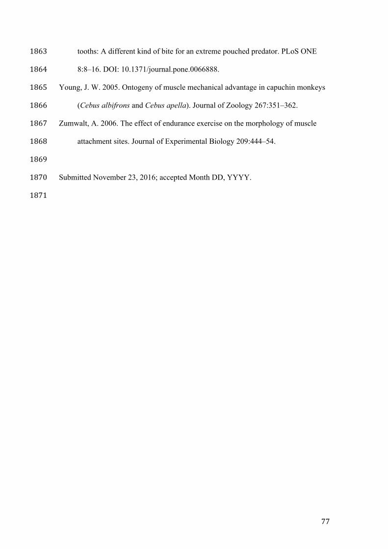
77
tooths: A different kind of bite for an extreme pouched predator. PLoS ONE 1863
8:8–16. DOI: 10.1371/journal.pone.0066888. 1864
Young, J. W. 2005. Ontogeny of muscle mechanical advantage in capuchin monkeys 1865
(Cebus albifrons and Cebus apella). Journal of Zoology 267:351–362. 1866
Zumwalt, A. 2006. The effect of endurance exercise on the morphology of muscle 1867
attachment sites. Journal of Experimental Biology 209:444–54. 1868
1869
Submitted November 23, 2016; accepted Month DD, YYYY. 1870
1871

78
1872
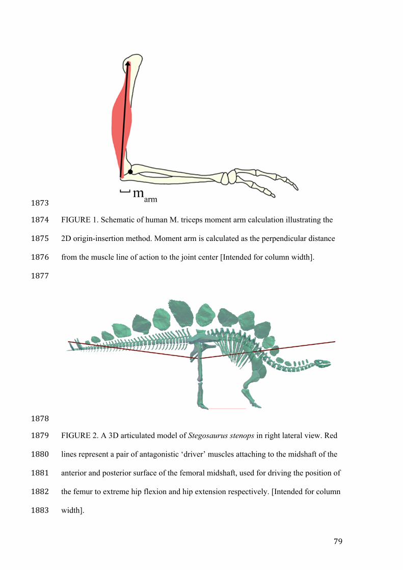
79
1873
FIGURE 1. Schematic of human M. triceps moment arm calculation illustrating the 1874
2D origin-insertion method. Moment arm is calculated as the perpendicular distance 1875
from the muscle line of action to the joint center [Intended for column width]. 1876
1877
1878
FIGURE 2. A 3D articulated model of Stegosaurus stenops in right lateral view. Red 1879
lines represent a pair of antagonistic ‘driver’ muscles attaching to the midshaft of the 1880
anterior and posterior surface of the femoral midshaft, used for driving the position of 1881
the femur to extreme hip flexion and hip extension respectively. [Intended for column 1882
width]. 1883
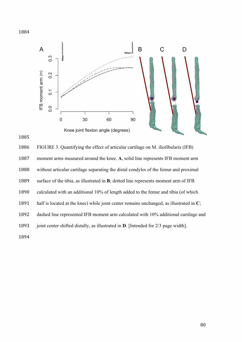
80
1884
1885
FIGURE 3. Quantifying the effect of articular cartilage on M. iliofibularis (IFB) 1886
moment arms measured around the knee. A, solid line represents IFB moment arm 1887
without articular cartilage separating the distal condyles of the femur and proximal 1888
surface of the tibia, as illustrated in B; dotted line represents moment arm of IFB 1889
calculated with an additional 10% of length added to the femur and tibia (of which 1890
half is located at the knee) while joint center remains unchanged, as illustrated in C; 1891
dashed line represented IFB moment arm calculated with 10% additional cartilage and 1892
joint center shifted distally, as illustrated in D. [Intended for 2/3 page width]. 1893
1894
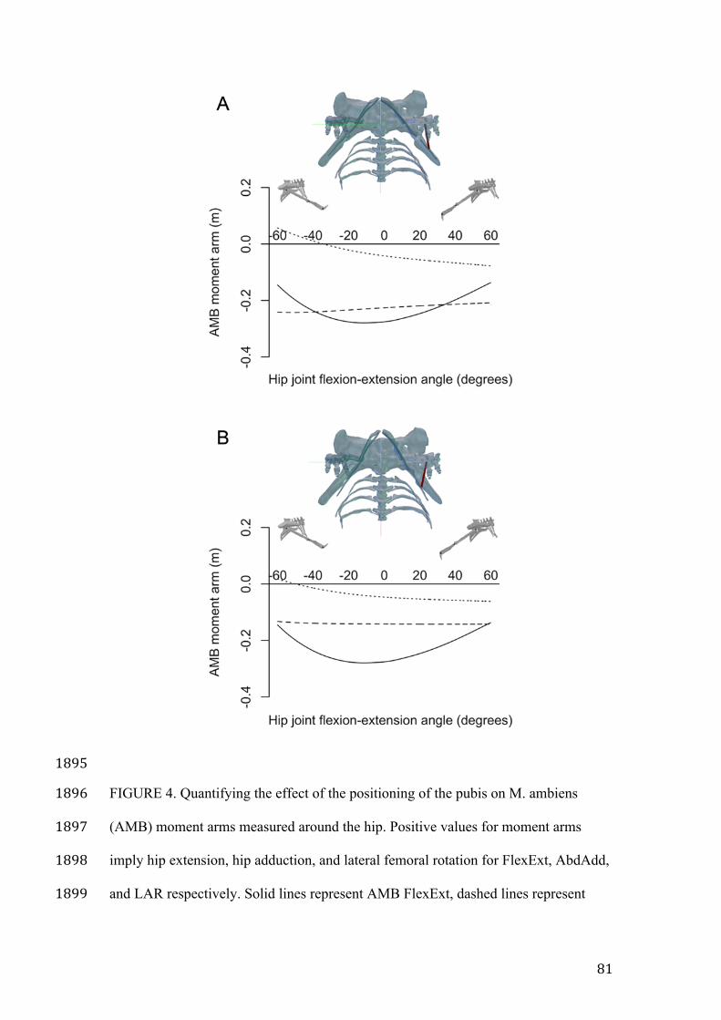
81
1895
FIGURE 4. Quantifying the effect of the positioning of the pubis on M. ambiens 1896
(AMB) moment arms measured around the hip. Positive values for moment arms 1897
imply hip extension, hip adduction, and lateral femoral rotation for FlexExt, AbdAdd, 1898
and LAR respectively. Solid lines represent AMB FlexExt, dashed lines represent 1899
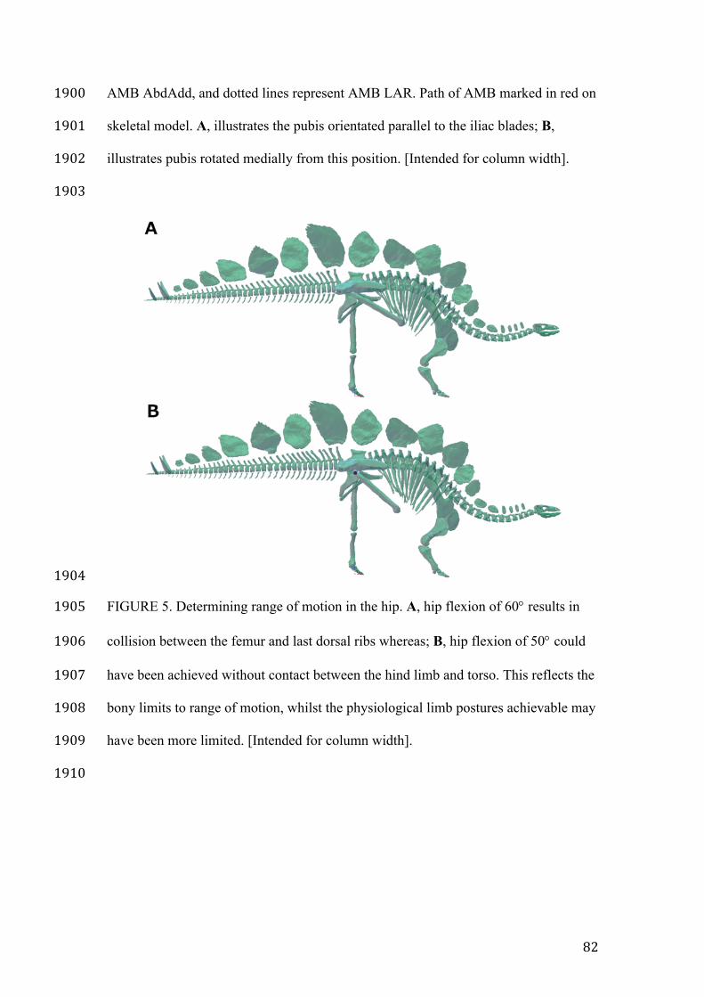
82
AMB AbdAdd, and dotted lines represent AMB LAR. Path of AMB marked in red on 1900
skeletal model. A, illustrates the pubis orientated parallel to the iliac blades; B, 1901
illustrates pubis rotated medially from this position. [Intended for column width]. 1902
1903
1904
FIGURE 5. Determining range of motion in the hip. A, hip flexion of 60° results in 1905
collision between the femur and last dorsal ribs whereas; B, hip flexion of 50° could 1906
have been achieved without contact between the hind limb and torso. This reflects the 1907
bony limits to range of motion, whilst the physiological limb postures achievable may 1908
have been more limited. [Intended for column width]. 1909
1910
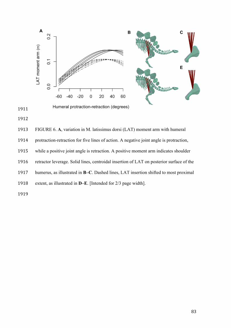
83
1911
1912
FIGURE 6. A, variation in M. latissimus dorsi (LAT) moment arm with humeral 1913
protraction-retraction for five lines of action. A negative joint angle is protraction, 1914
while a positive joint angle is retraction. A positive moment arm indicates shoulder 1915
retractor leverage. Solid lines, centroidal insertion of LAT on posterior surface of the 1916
humerus, as illustrated in B–C. Dashed lines, LAT insertion shifted to most proximal 1917
extent, as illustrated in D–E. [Intended for 2/3 page width]. 1918
1919
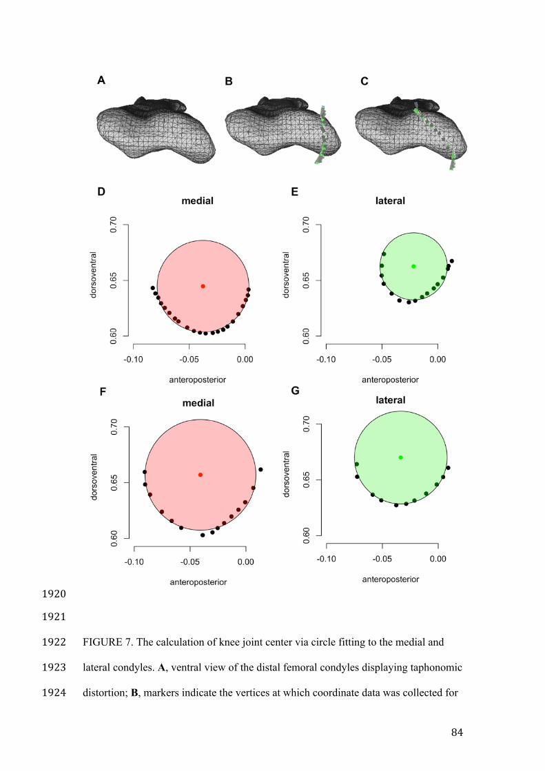
84
1920
1921
FIGURE 7. The calculation of knee joint center via circle fitting to the medial and 1922
lateral condyles. A, ventral view of the distal femoral condyles displaying taphonomic 1923
distortion; B, markers indicate the vertices at which coordinate data was collected for 1924
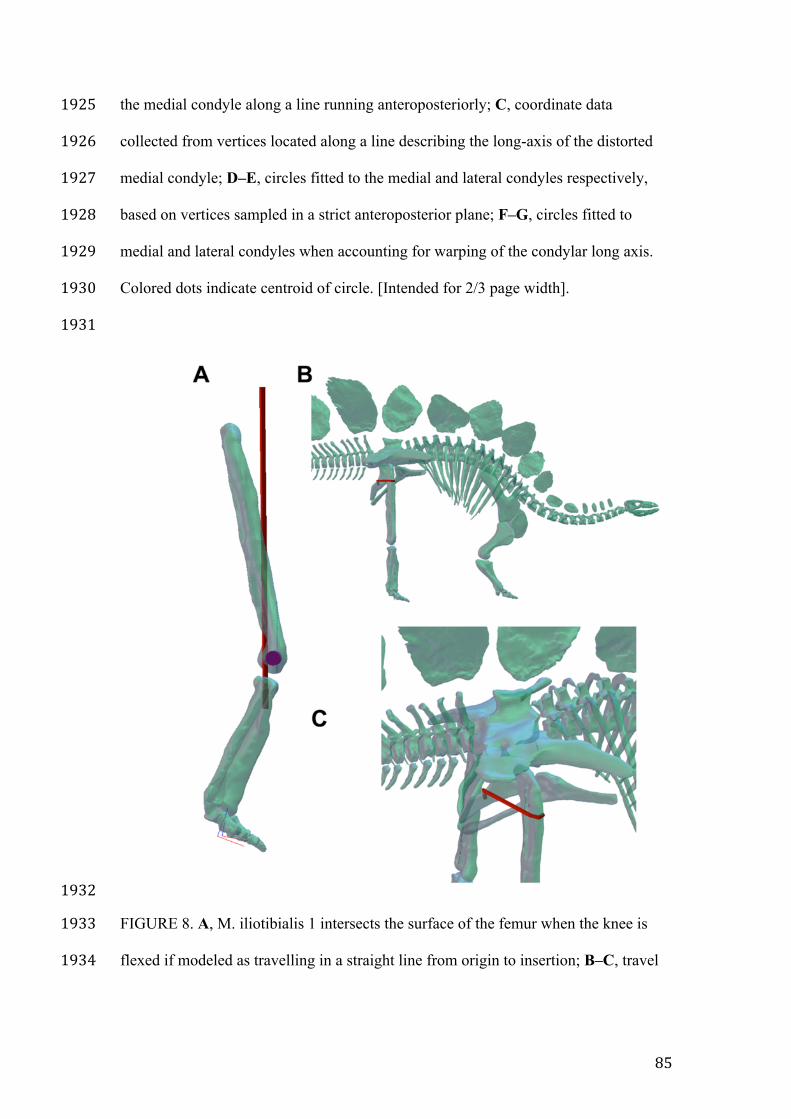
85
the medial condyle along a line running anteroposteriorly; C, coordinate data 1925
collected from vertices located along a line describing the long-axis of the distorted 1926
medial condyle; D–E, circles fitted to the medial and lateral condyles respectively, 1927
based on vertices sampled in a strict anteroposterior plane; F–G, circles fitted to 1928
medial and lateral condyles when accounting for warping of the condylar long axis. 1929
Colored dots indicate centroid of circle. [Intended for 2/3 page width]. 1930
1931
1932
FIGURE 8. A, M. iliotibialis 1 intersects the surface of the femur when the knee is 1933
flexed if modeled as travelling in a straight line from origin to insertion; B–C, travel 1934
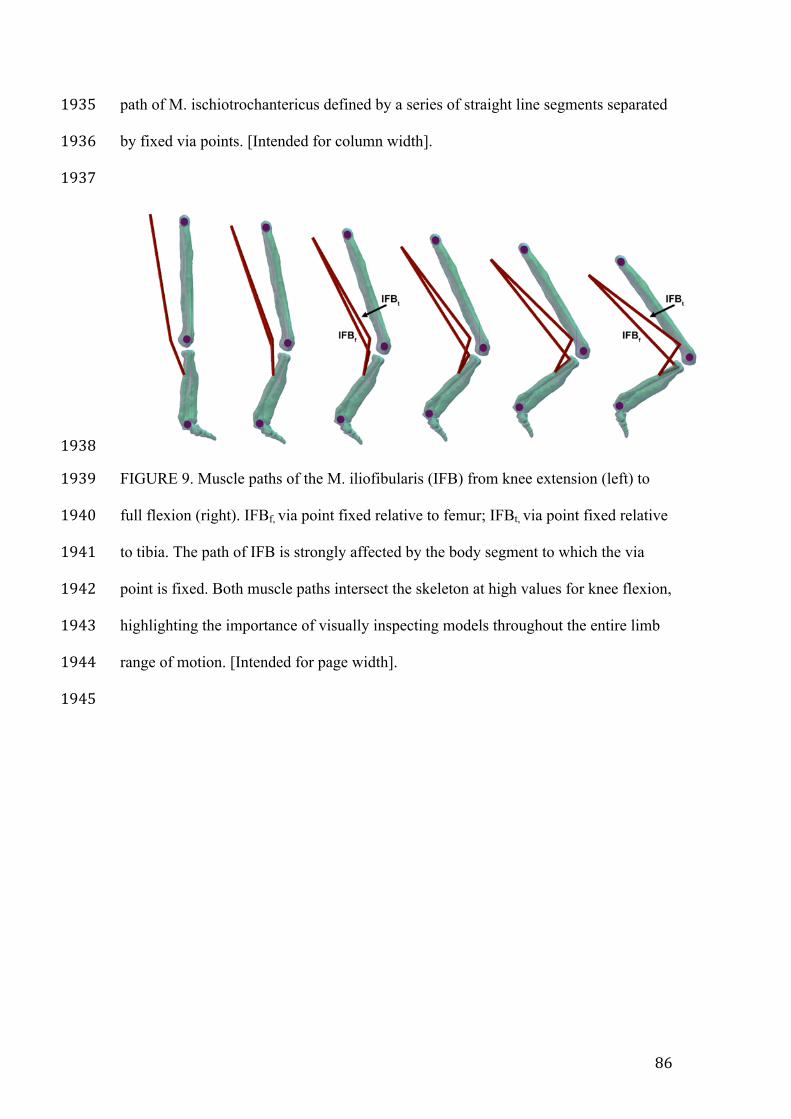
86
path of M. ischiotrochantericus defined by a series of straight line segments separated 1935
by fixed via points. [Intended for column width]. 1936
1937
1938
FIGURE 9. Muscle paths of the M. iliofibularis (IFB) from knee extension (left) to 1939
full flexion (right). IFBf, via point fixed relative to femur; IFBt, via point fixed relative 1940
to tibia. The path of IFB is strongly affected by the body segment to which the via 1941
point is fixed. Both muscle paths intersect the skeleton at high values for knee flexion, 1942
highlighting the importance of visually inspecting models throughout the entire limb 1943
range of motion. [Intended for page width]. 1944
1945
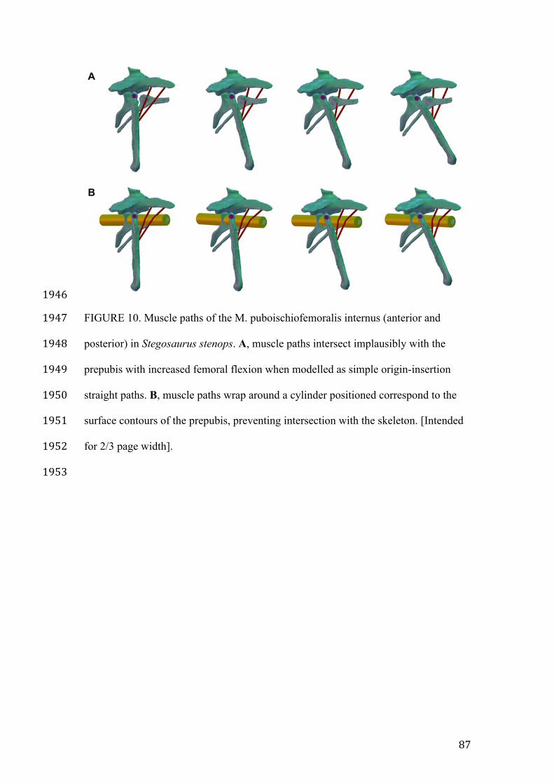
87
1946
FIGURE 10. Muscle paths of the M. puboischiofemoralis internus (anterior and 1947
posterior) in Stegosaurus stenops. A, muscle paths intersect implausibly with the 1948
prepubis with increased femoral flexion when modelled as simple origin-insertion 1949
straight paths. B, muscle paths wrap around a cylinder positioned correspond to the 1950
surface contours of the prepubis, preventing intersection with the skeleton. [Intended 1951
for 2/3 page width]. 1952
1953
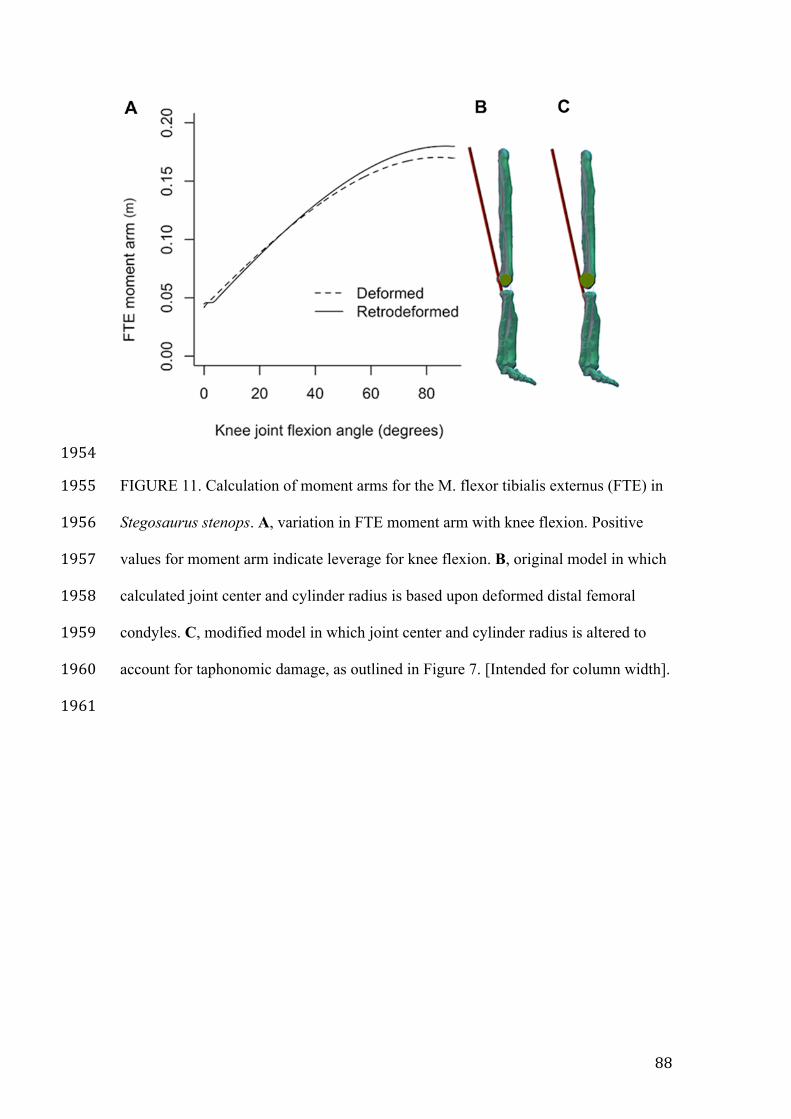
88
1954
FIGURE 11. Calculation of moment arms for the M. flexor tibialis externus (FTE) in 1955
Stegosaurus stenops. A, variation in FTE moment arm with knee flexion. Positive 1956
values for moment arm indicate leverage for knee flexion. B, original model in which 1957
calculated joint center and cylinder radius is based upon deformed distal femoral 1958
condyles. C, modified model in which joint center and cylinder radius is altered to 1959
account for taphonomic damage, as outlined in Figure 7. [Intended for column width]. 1960
1961
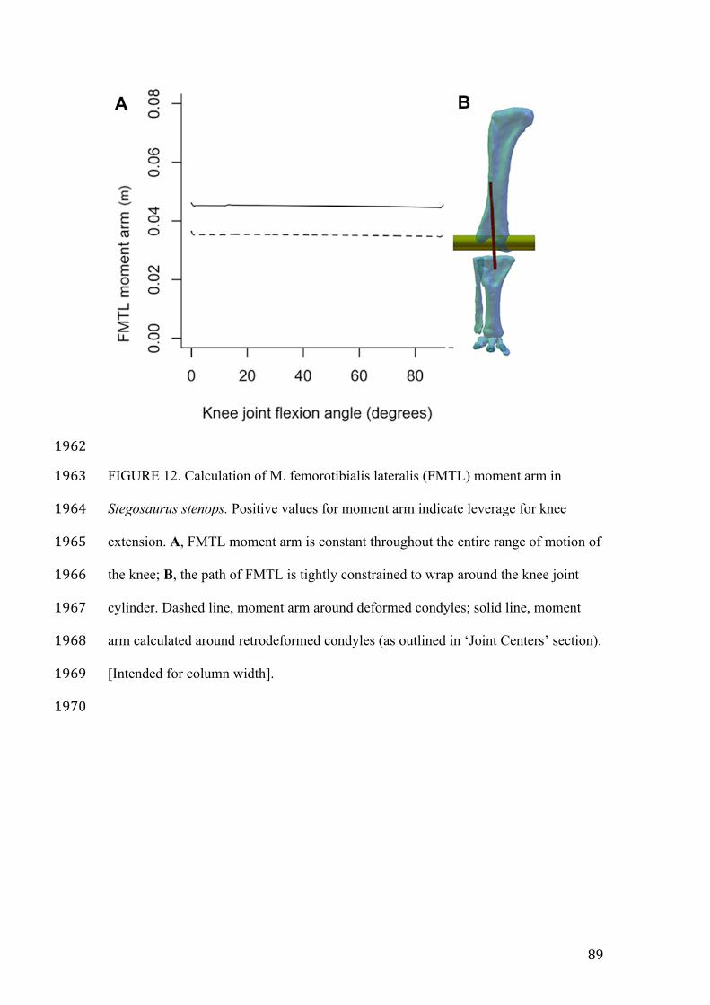
89
1962
FIGURE 12. Calculation of M. femorotibialis lateralis (FMTL) moment arm in 1963
Stegosaurus stenops. Positive values for moment arm indicate leverage for knee 1964
extension. A, FMTL moment arm is constant throughout the entire range of motion of 1965
the knee; B, the path of FMTL is tightly constrained to wrap around the knee joint 1966
cylinder. Dashed line, moment arm around deformed condyles; solid line, moment 1967
arm calculated around retrodeformed condyles (as outlined in ‘Joint Centers’ section). 1968
[Intended for column width]. 1969
1970
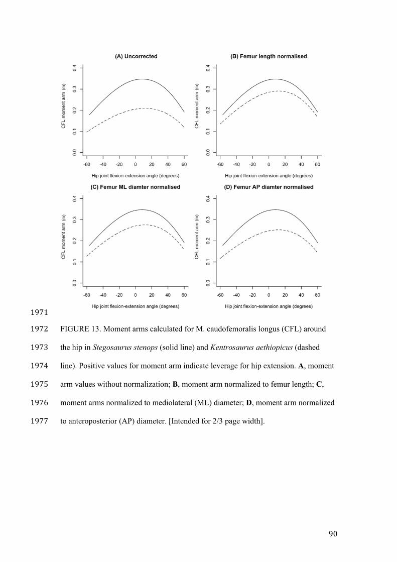
90
1971
FIGURE 13. Moment arms calculated for M. caudofemoralis longus (CFL) around 1972
the hip in Stegosaurus stenops (solid line) and Kentrosaurus aethiopicus (dashed 1973
line). Positive values for moment arm indicate leverage for hip extension. A, moment 1974
arm values without normalization; B, moment arm normalized to femur length; C, 1975
moment arms normalized to mediolateral (ML) diameter; D, moment arm normalized 1976
to anteroposterior (AP) diameter. [Intended for 2/3 page width]. 1977

![INDEX [] · Index 243 Brackley, Northants., 229 Bradford, 19, 30 Bradshaw, Thomas, 202 Brannigan, Lawrence, 221 Branthwait, Alexander, 202 Brassey, J., 11](https://img.pdfslide.us/doc/110x75/5f46ac876cd59369a9456f76/index-index-243-brackley-northants-229-bradford-19-30-bradshaw-thomas.jpg)