Embed Size (px)
Citation preview

© 2012 Stanley Black & Decker, Inc.New Britain, CT 06053
U.S.A.65778 12/2012 Ver. 10
Safety, OperatiOn and Maintenance
USer ManUaL
BR87HYDRAULIC
BREAKER
2 ► BR87 User Manual
DECLARATION OF CONFORMITY
DECLARATION OF CONFORMITYÜBEREINSTIMMUNGS-ERKLARUNGDECLARATION DE CONFORMITE CEE DECLARACION DE CONFORMIDADDICHIARAZIONE DI CONFORMITA
Hydraulic Tools
______________________________________________________________________I, the undersigned:Ich, der Unterzeichnende:Je soussigné:El abajo firmante:lo sottoscritto:
Weisbeck, Andy Surname and First names/Familiennname und Vornamen/Nom et prénom/Nombre y apellido/Cognome e nome
hereby declare that the equipment specified hereunder:bestätige hiermit, daß erklaren Produkt genannten Werk oder Gerät:déclare que l’équipement visé ci-dessous:Por la presente declaro que el equipo se especifica a continuación:Dichiaro che le apparecchiature specificate di seguito:
1. Category: Hydraulic Hand Held Concrete BreakerKategorie:Catégorie:Categoria:Categoria:
2. Make/Marke/Marque/Marca/Marca Stanley
3. Type/Typ/Type/Tipo/Tipo: BR8713201, BR8717201, BR873204. Serial number of equipment:
Seriennummer des Geräts:Numéro de série de l’équipement:Numero de serie del equipo:Matricola dell´attrezzatura:
BR8713201 AllBR8717201 AllBR87320 Serial # 031312004 and above
5. Mass/Masse/Masse/Masa/Massa 38 kg
Has been manufactured in conformity with Wurde hergestellt in Übereinstimmung mit Est fabriqué conformément Ha sido fabricado de acuerdo conE’ stata costruita in conformitá con
Directive/StandardsRichtlinie/StandardsDirectives/NormesDirectriz/Los NormasDirettiva/Norme
No.NrNuméroNon.
Approved bodyPrüfung durchOrganisme agrééAprobadoCollaudato
ISONoise Directive
Machinery DirectiveISO
11148-4:20102000/14/EC:2005
2006/42/EC:200628927-10:2011
SelfAkustikNet (Notified body ID 1585)Bagsvard Hovedgade 141, 2880 Bagsvard, DenmarkCertificate #863/2011/005SelfSelf
6. Special Provisions: None 7. Measurements: Measured Sound Power Level 105 LwASpezielle Bestimmungen: Messungen Guaranteed Sound Power Level 106 LwADispositions particulières: Mesures Measured in accordance to Directive 2000/14/EC,Provisiones especiales: Mediciones Annex III, Part B, No 10, m ≥ 30Disposizioni speciali: Misurazioni
8. Representative in the Union: Patrick Vervier, Stanley Dubuis 17-19, rue Jules Berthonneau-BP 3406 41034 Blois Cedex, France. Vertreter in der Union/Représentant dans l’union/Representante en la Union/Rappresentante presso l’Unione
Done at/Ort/Fait à/Dado en/Fatto a Stanley Hydraulic Tools, Milwaukie, Oregon USA Date/Datum/le/Fecha/Data 1-30-12
Signature/Unterschrift/Signature/Firma/Firma
Position/Position/Fonction/Cargo/Posizione Engineering Manager
BR87 User Manual ◄ 3
TABLE OF CONTENTS
DECLARATION OF CONFORMITY ..........................................................................................................................2SAFETY SYMBOLS ..................................................................................................................................................4SAFETY PRECAUTIONS ..........................................................................................................................................5TOOL STICKERS & TAGS ........................................................................................................................................7HOSE TYPES ............................................................................................................................................................8HOSE RECOMMENDATIONS ..................................................................................................................................9
FIGURE 1. TYPICAL HOSE CONNECTIONS .......................................................................................................9HTMA REQUIREMENTS .........................................................................................................................................10OPERATION ............................................................................................................................................................ 11TOOL PROTECTION & CARE ................................................................................................................................12TROUBLESHOOTING ............................................................................................................................................13CHARGING THE ACCUMULATOR .........................................................................................................................14
FIGURE 2. CHARGING THE ACCUMULATOR ...................................................................................................15SPECIFICATIONS ...................................................................................................................................................16ACCESSORIES.......................................................................................................................................................17SERVICE TOOLS ....................................................................................................................................................17BR87 PARTS ILLUSTRATION ................................................................................................................................18BR87 PARTS LIST ..................................................................................................................................................20
SERVICING: This manual contains safety, operation, and routine maintenance instructions. Stanley Hydraulic Tools recommends that servicing of hydraulic tools, other than routine maintenance, must be performed by an authorized and certified dealer. Please read the following warning.
For the nearest authorized and certified dealer, call Stanley Hydraulic Tools at the number listed on the back of this manual and ask for a Customer Service Representative.
WARNING
SERIOUS INJURY OR DEATH COULD RESULT FROM THE IMPROPER REPAIR OR SERVICE OF THIS TOOL.
REPAIRS AND / OR SERVICE TO THIS TOOL MUST ONLY BE DONE BY AN AUTHORIZED AND CERTIFIED DEALER.
IMPORTANT
To fill out a Product Warranty Recording form, and for information on your warranty, visit Stanleyhydraulic.com and select the Warranty tab.
(NOTE: The warranty recording form must be submitted to validate the warranty).
4 ► BR87 User Manual
SAFETY SYMBOLS
Always observe safety symbols. They are included for your safety and for the protection of the tool.
LOCAL SAFETY REGULATIONSEnter any local safety regulations here. Keep these instructions in an area accessible to the operator and mainte-nance personnel.
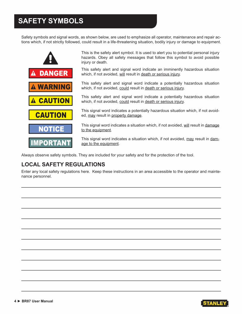
Safety symbols and signal words, as shown below, are used to emphasize all operator, maintenance and repair ac-tions which, if not strictly followed, could result in a life-threatening situation, bodily injury or damage to equipment.
This is the safety alert symbol. It is used to alert you to potential personal injury hazards. Obey all safety messages that follow this symbol to avoid possible injury or death.
DANGERThis safety alert and signal word indicate an imminently hazardous situation which, if not avoided, will result in death or serious injury.
WARNINGThis safety alert and signal word indicate a potentially hazardous situation which, if not avoided, could result in death or serious injury.
CAUTIONThis safety alert and signal word indicate a potentially hazardous situation which, if not avoided, could result in death or serious injury.
CAUTIONThis signal word indicates a potentially hazardous situation which, if not avoid-ed, may result in property damage.
NOTICEThis signal word indicates a situation which, if not avoided, will result in damage to the equipment.
IMPORTANTThis signal word indicates a situation which, if not avoided, may result in dam-age to the equipment.
BR87 User Manual ◄ 5
SAFETY PRECAUTIONS
Tool operators and maintenance personnel must always comply with the safety precautions given in this manual and on the stickers and tags attached to the tool and hose.These safety precautions are given for your safety. Re-view them carefully before operating the tool and before performing general maintenance or repairs.Supervising personnel should develop additional pre-cautions relating to the specific work area and local safety regulations. If so, place the added precautions in the space provided in this manual.The BR87 Hydraulic Breaker will provide safe and de-pendable service if operated in accordance with the in-structions given in this manual. Read and understand this manual and any stickers and tags attached to the tool and hoses before operation. Failure to do so could result in personal injury or equipment damage.
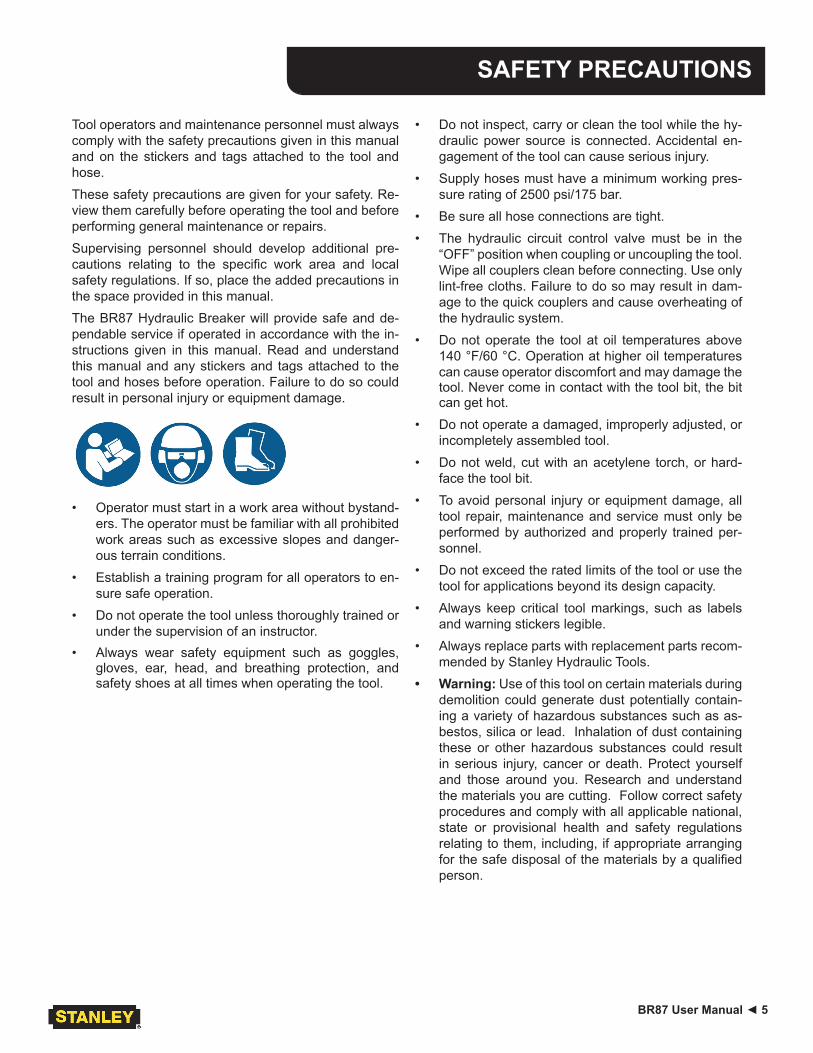
• Operator must start in a work area without bystand-ers. The operator must be familiar with all prohibited work areas such as excessive slopes and danger-ous terrain conditions.
• Establish a training program for all operators to en-sure safe operation.
• Do not operate the tool unless thoroughly trained or under the supervision of an instructor.
• Always wear safety equipment such as goggles, gloves, ear, head, and breathing protection, and safety shoes at all times when operating the tool.
• Do not inspect, carry or clean the tool while the hy-draulic power source is connected. Accidental en-gagement of the tool can cause serious injury.
• Supply hoses must have a minimum working pres-sure rating of 2500 psi/175 bar.
• Be sure all hose connections are tight.• The hydraulic circuit control valve must be in the
“OFF” position when coupling or uncoupling the tool. Wipe all couplers clean before connecting. Use only lint-free cloths. Failure to do so may result in dam-age to the quick couplers and cause overheating of the hydraulic system.
• Do not operate the tool at oil temperatures above 140 °F/60 °C. Operation at higher oil temperatures can cause operator discomfort and may damage the tool. Never come in contact with the tool bit, the bit can get hot.
• Do not operate a damaged, improperly adjusted, or incompletely assembled tool.
• Do not weld, cut with an acetylene torch, or hard-face the tool bit.
• To avoid personal injury or equipment damage, all tool repair, maintenance and service must only be performed by authorized and properly trained per-sonnel.
• Do not exceed the rated limits of the tool or use the tool for applications beyond its design capacity.
• Always keep critical tool markings, such as labels and warning stickers legible.
• Always replace parts with replacement parts recom-mended by Stanley Hydraulic Tools.
• Warning: Use of this tool on certain materials during demolition could generate dust potentially contain-ing a variety of hazardous substances such as as-bestos, silica or lead. Inhalation of dust containing these or other hazardous substances could result in serious injury, cancer or death. Protect yourself and those around you. Research and understand the materials you are cutting. Follow correct safety procedures and comply with all applicable national, state or provisional health and safety regulations relating to them, including, if appropriate arranging for the safe disposal of the materials by a qualified person.
6 ► BR87 User Manual
SAFETY PRECAUTIONS
• Check fastener tightness often and before each use daily.
• Never operate the tool if you cannot be sure that underground utilities are not present.
• Do not wear loose fitting clothing when operating the tool.
• Warning: Hydraulic fluid under pressure could cause skin injection injury. If you are injured by hydraulic fluid, get medical attention immediately.
• Keep all body parts away from the working tool.• When handling material or the tool bit, wear your
(PPE) Personal Protection Equipment.• Be observant of the hydraulic hoses lying about the
work area, they can be a tripping hazard.• Always de-energize the hydraulic system when
changing a tool bit.
• Take caution when changing a tool bit, tool bits can get very hot.
• Never use the tool in an explosive atmosphere, sparks from the breaking process could ignite ex-plosive gas.
• Use proper lifting techniques when handling the tool, get help from a co-worker and do not over-reach.
• Use proper protection from falling or flying debris, keep bystanders at a safe distance.
• Do not exceed the rated flow and pressure. See Specifications in this manual for correct flow rate and pressure rating. Rapid failure of the internal seals may result.
BR87 User Manual ◄ 7
TOOL STICKERS & TAGS
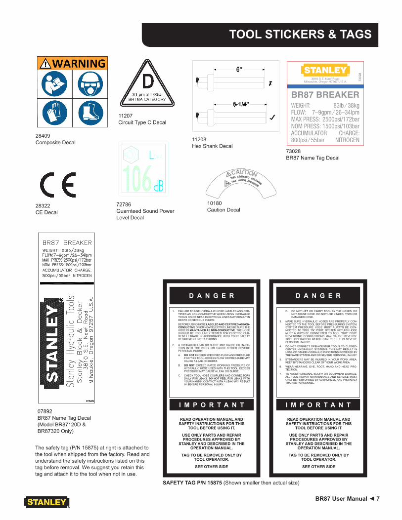
The safety tag (P/N 15875) at right is attached to the tool when shipped from the factory. Read and understand the safety instructions listed on this tag before removal. We suggest you retain this tag and attach it to the tool when not in use.
28322CE Decal
11207Circuit Type C Decal
SAFETY TAG P/N 15875 (Shown smaller then actual size)
D A N G E RD A N G E R
READ OPERATION MANUAL AND SAFETY INSTRUCTIONS FOR THIS
TOOL BEFORE USING IT.
USE ONLY PARTS AND REPAIR PROCEDURES APPROVED BY
STANLEY AND DESCRIBED IN THE OPERATION MANUAL.
TAG TO BE REMOVED ONLY BY TOOL OPERATOR.
SEE OTHER SIDE
1. FAILURE TO USE HYDRAULIC HOSE LABELED AND CER-TIFIED AS NON-CONDUCTIVE WHEN USING HYDRAULIC TOOLS ON OR NEAR ELECTRICAL LINES MAY RESULT IN DEATH OR SERIOUS INJURY.BEFORE USING HOSE LABELED AND CERTIFIED AS NON-CONDUCTIVE ON OR NEAR ELECTRIC LINES BE SURE THE HOSE IS MAINTAINED AS NON-CONDUCTIVE. THE HOSE SHOULD BE REGULARLY TESTED FOR ELECTRIC CUR-RENT LEAKAGE IN ACCORDANCE WITH YOUR SAFETY DEPARTMENT INSTRUCTIONS.
2. A HYDRAULIC LEAK OR BURST MAY CAUSE OIL INJEC-TION INTO THE BODY OR CAUSE OTHER SEVERE PERSONAL INJURY.A. DO NOT EXCEED SPECIFIED FLOW AND PRESSURE
FOR THIS TOOL. EXCESS FLOW OR PRESSURE MAY CAUSE A LEAK OR BURST.
B. DO NOT EXCEED RATED WORKING PRESSURE OF HYDRAULIC HOSE USED WITH THIS TOOL. EXCESS PRESSURE MAY CAUSE A LEAK OR BURST.
C. CHECK TOOL HOSE COUPLERS AND CONNECTORS DAILY FOR LEAKS. DO NOT FEEL FOR LEAKS WITH YOUR HANDS. CONTACT WITH A LEAK MAY RESULT IN SEVERE PERSONAL INJURY.
I M P O R T A N T
D. DO NOT LIFT OR CARRY TOOL BY THE HOSES. DO NOT ABUSE HOSE. DO NOT USE KINKED, TORN OR DAMAGED HOSE.
3. MAKE SURE HYDRAULIC HOSES ARE PROPERLY CON-NECTED TO THE TOOL BEFORE PRESSURING SYSTEM. SYSTEM PRESSURE HOSE MUST ALWAYS BE CON-NECTED TO TOOL “IN” PORT. SYSTEM RETURN HOSE MUST ALWAYS BE CONNECTED TO TOOL “OUT” PORT. REVERSING CONNECTIONS MAY CAUSE REVERSE TOOL OPERATION WHICH CAN RESULT IN SEVERE PERSONAL INJURY.
4. DO NOT CONNECT OPEN-CENTER TOOLS TO CLOSED-CENTER HYDRAULIC SYSTEMS. THIS MAY RESULT IN LOSS OF OTHER HYDRAULIC FUNCTIONS POWERED BY THE SAME SYSTEM AND/OR SEVERE PERSONAL INJURY.
5. BYSTANDERS MAY BE INJURED IN YOUR WORK AREA. KEEP BYSTANDERS CLEAR OF YOUR WORK AREA.
6. WEAR HEARING, EYE, FOOT, HAND AND HEAD PRO-TECTION.
7. TO AVOID PERSONAL INJURY OR EQUIPMENT DAMAGE, ALL TOOL REPAIR MAINTENANCE AND SERVICE MUST ONLY BE PERFORMED BY AUTHORIZED AND PROPERLY TRAINED PERSONNEL.
I M P O R T A N T
READ OPERATION MANUAL AND SAFETY INSTRUCTIONS FOR THIS
TOOL BEFORE USING IT.
USE ONLY PARTS AND REPAIR PROCEDURES APPROVED BY
STANLEY AND DESCRIBED IN THE OPERATION MANUAL.
TAG TO BE REMOVED ONLY BY TOOL OPERATOR.
SEE OTHER SIDE
72786Guarnteed Sound Power Level Decal
28409Composite Decal
10180Caution Decal
07892BR87 Name Tag Decal (Model BR87120D & BR87320 Only)
11208Hex Shank Decal
Black
WEIGHT: FLOW:MAX PRESS:NOM PRESS:ACCUMULATOR800psi ⁄ 55bar
83lb ⁄ 38kg7–9gpm ⁄ 26–34lpm
2500psi/172bar1500psi/103bar
CHARGE:NITROGEN
3810 S.E. Naef RoadMilwaukie, Oregon 97267 U.S.A.
BR87 BREAKER
7302
8
73028BR87 Name Tag Decal
8 ► BR87 User Manual
HOSE TYPES
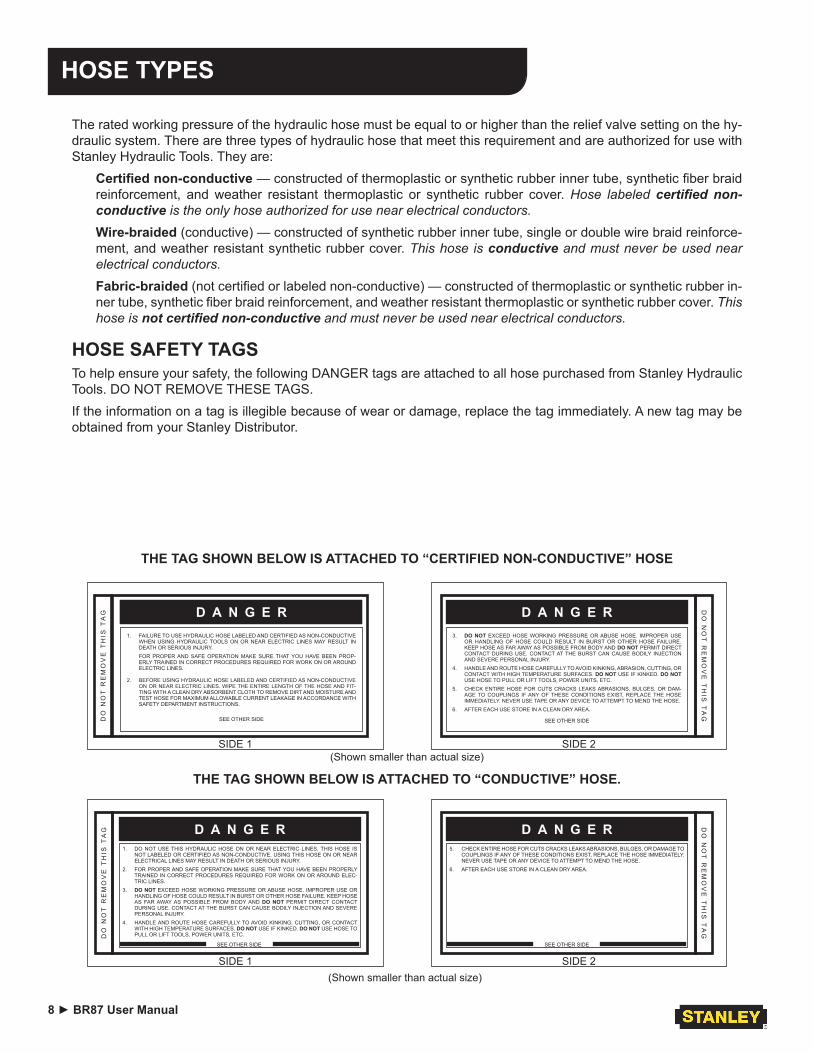
The rated working pressure of the hydraulic hose must be equal to or higher than the relief valve setting on the hy-draulic system. There are three types of hydraulic hose that meet this requirement and are authorized for use with Stanley Hydraulic Tools. They are:
Certified non-conductive — constructed of thermoplastic or synthetic rubber inner tube, synthetic fiber braid reinforcement, and weather resistant thermoplastic or synthetic rubber cover. Hose labeled certified non-conductive is the only hose authorized for use near electrical conductors.Wire-braided (conductive) — constructed of synthetic rubber inner tube, single or double wire braid reinforce-ment, and weather resistant synthetic rubber cover. This hose is conductive and must never be used near electrical conductors.Fabric-braided (not certified or labeled non-conductive) — constructed of thermoplastic or synthetic rubber in-ner tube, synthetic fiber braid reinforcement, and weather resistant thermoplastic or synthetic rubber cover. This hose is not certified non-conductive and must never be used near electrical conductors.
HOSE SAFETY TAGSTo help ensure your safety, the following DANGER tags are attached to all hose purchased from Stanley Hydraulic Tools. DO NOT REMOVE THESE TAGS.If the information on a tag is illegible because of wear or damage, replace the tag immediately. A new tag may be obtained from your Stanley Distributor.
THE TAG SHOWN BELOW IS ATTACHED TO “CERTIFIED NON-CONDUCTIVE” HOSE
THE TAG SHOWN BELOW IS ATTACHED TO “CONDUCTIVE” HOSE.
(Shown smaller than actual size)SIDE 1
D A N G E R1. FAILURE TO USE HYDRAULIC HOSE LABELED AND CERTIFIED AS NON-CONDUCTIVE
WHEN USING HYDRAULIC TOOLS ON OR NEAR ELECTRIC LINES MAY RESULT IN DEATH OR SERIOUS INJURY.FOR PROPER AND SAFE OPERATION MAKE SURE THAT YOU HAVE BEEN PROP-ERLY TRAINED IN CORRECT PROCEDURES REQUIRED FOR WORK ON OR AROUND ELECTRIC LINES.
2. BEFORE USING HYDRAULIC HOSE LABELED AND CERTIFIED AS NON-CONDUCTIVE ON OR NEAR ELECTRIC LINES. WIPE THE ENTIRE LENGTH OF THE HOSE AND FIT-TING WITH A CLEAN DRY ABSORBENT CLOTH TO REMOVE DIRT AND MOISTURE AND TEST HOSE FOR MAXIMUM ALLOWABLE CURRENT LEAKAGE IN ACCORDANCE WITH SAFETY DEPARTMENT INSTRUCTIONS.
SEE OTHER SIDE
SIDE 2
DO
NO
T R
EM
OV
E T
HIS
TA
G
3. DO NOT EXCEED HOSE WORKING PRESSURE OR ABUSE HOSE. IMPROPER USE OR HANDLING OF HOSE COULD RESULT IN BURST OR OTHER HOSE FAILURE. KEEP HOSE AS FAR AWAY AS POSSIBLE FROM BODY AND DO NOT PERMIT DIRECT CONTACT DURING USE. CONTACT AT THE BURST CAN CAUSE BODILY INJECTION AND SEVERE PERSONAL INJURY.
4. HANDLE AND ROUTE HOSE CAREFULLY TO AVOID KINKING, ABRASION, CUTTING, OR CONTACT WITH HIGH TEMPERATURE SURFACES. DO NOT USE IF KINKED. DO NOT USE HOSE TO PULL OR LIFT TOOLS, POWER UNITS, ETC.
5. CHECK ENTIRE HOSE FOR CUTS CRACKS LEAKS ABRASIONS, BULGES, OR DAM-AGE TO COUPLINGS IF ANY OF THESE CONDITIONS EXIST, REPLACE THE HOSE IMMEDIATELY. NEVER USE TAPE OR ANY DEVICE TO ATTEMPT TO MEND THE HOSE.
6. AFTER EACH USE STORE IN A CLEAN DRY AREA.
SEE OTHER SIDE
D A N G E R
DO
NO
T R
EM
OV
E T
HIS
TA
G D A N G E R
(Shown smaller than actual size)SIDE 2
5. CHECK ENTIRE HOSE FOR CUTS CRACKS LEAKS ABRASIONS, BULGES, OR DAMAGE TO COUPLINGS IF ANY OF THESE CONDITIONS EXIST, REPLACE THE HOSE IMMEDIATELY. NEVER USE TAPE OR ANY DEVICE TO ATTEMPT TO MEND THE HOSE.
6. AFTER EACH USE STORE IN A CLEAN DRY AREA.
D A N G E R DO
NO
T R
EM
OV
E T
HIS
TA
G
D A N G E R
SIDE 1
1. DO NOT USE THIS HYDRAULIC HOSE ON OR NEAR ELECTRIC LINES. THIS HOSE IS NOT LABELED OR CERTIFIED AS NON-CONDUCTIVE. USING THIS HOSE ON OR NEAR ELECTRICAL LINES MAY RESULT IN DEATH OR SERIOUS INJURY.
2. FOR PROPER AND SAFE OPERATION MAKE SURE THAT YOU HAVE BEEN PROPERLY TRAINED IN CORRECT PROCEDURES REQUIRED FOR WORK ON OR AROUND ELEC-TRIC LINES.
3. DO NOT EXCEED HOSE WORKING PRESSURE OR ABUSE HOSE. IMPROPER USE OR HANDLING OF HOSE COULD RESULT IN BURST OR OTHER HOSE FAILURE. KEEP HOSE AS FAR AWAY AS POSSIBLE FROM BODY AND DO NOT PERMIT DIRECT CONTACT DURING USE. CONTACT AT THE BURST CAN CAUSE BODILY INJECTION AND SEVERE PERSONAL INJURY.
4. HANDLE AND ROUTE HOSE CAREFULLY TO AVOID KINKING, CUTTING, OR CONTACT WITH HIGH TEMPERATURE SURFACES. DO NOT USE IF KINKED. DO NOT USE HOSE TO PULL OR LIFT TOOLS, POWER UNITS, ETC.D
O N
OT
RE
MO
VE
TH
IS T
AG D A N G E R
SEE OTHER SIDE SEE OTHER SIDE
BR87 User Manual ◄ 9
HOSE RECOMMENDATIONSO
il Fl
owH
ose
Leng
ths
Insi
de D
iam
eter
USE
(Pre
ss/R
etur
n)
Min
. Wor
king
Pre
ssur
eG
PMLP
MFE
ETM
ETER
SIN
CH
MM
PSI
BA
RC
ertifi
ed N
on-C
ondu
ctiv
e H
ose
- Fib
er B
raid
- fo
r Util
ity B
ucke
t Tru
cks
4-9
15-3
4up
to 1
0up
to 3
3/8
10B
oth
2250
155
Con
duct
ive
Hos
e - W
ire B
raid
or F
iber
Bra
id -D
O N
OT
USE
NEA
R E
LEC
TRIC
AL
CO
ND
UC
TOR
S4-
615
-23
up to
25
up to
7.5
3/8
10B
oth
2500
175
4-6
15-2
326
-100
7.5-
301/
213
Bot
h25
0017
5
5-10
.519
-40
up to
50
up to
15
1/2
13B
oth
2500
175
5-10
.519
-40
51-1
0015
-30
5/8
16B
oth
2500
175
5-10
.519
-40
100-
300
30-9
05/
816
Pre
ssur
e25
0017
5
3/4
19R
etur
n25
0017
5
10-1
338
-49
up to
50
up to
15
5/8
16B
oth
2500
175
10-1
338
-49
51-1
0015
-30
5/8
16P
ress
ure
2500
175
3/4
19R
etur
n25
0017
5
10-1
338
-49
100-
200
30-6
03/
419
Pre
ssur
e25
0017
5
125
.4R
etur
n25
0017
5
13-1
649
-60
up to
25
up to
85/
816
Pre
ssur
e25
0017
5
3/4
19R
etur
n25
0017
5
13-1
649
-60
26-1
008-
303/
419
Pre
ssur
e25
0017
5
125
.4R
etur
n25
0017
5
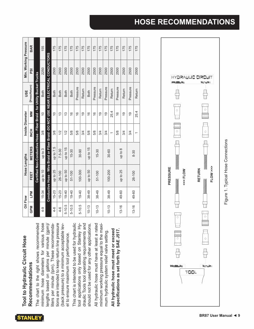
Figu
re 1
. Typ
ical
Hos
e C
onne
ctio
ns
Tool
to H
ydra
ulic
Circ
uit H
ose
Rec
omm
enda
tions
The
char
t to
the
rig
ht s
how
s re
com
men
ded
min
imum
hos
e di
amet
ers
for
vario
us h
ose
leng
ths
base
d on
gal
lons
per
min
ute
(gpm
)/lit
ers
per
min
ute
(lpm
). Th
ese
reco
mm
enda
-tio
ns a
re in
tend
ed to
kee
p re
turn
line
pre
ssur
e (b
ack
pres
sure
) to
a m
inim
um a
ccep
tabl
e le
v-el
to e
nsur
e m
axim
um to
ol p
erfo
rman
ce.
This
cha
rt is
inte
nded
to b
e us
ed fo
r hyd
raul
ic
tool
app
licat
ions
onl
y ba
sed
on S
tanl
ey H
y-dr
aulic
Too
ls to
ol o
pera
ting
requ
irem
ents
and
sh
ould
not
be
used
for a
ny o
ther
app
licat
ions
.A
ll hy
drau
lic h
ose
mus
t hav
e at
leas
t a r
ated
m
inim
um w
orki
ng p
ress
ure
equa
l to
the
max
i-m
um h
ydra
ulic
sys
tem
relie
f val
ve s
ettin
g.
All
hydr
aulic
hos
e m
ust m
eet o
r exc
eed
spec
ifica
tions
as
set f
orth
by
SAE
J517
.
PRES
SUR
E
RET
UR
N
<<<
FLO
W
FLO
W >
>>
10 ► BR87 User Manual
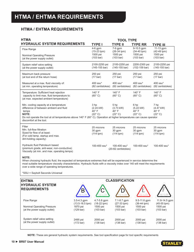
HTMA / EHTMA REQUIREMENTS
Flow Range
Nominal Operating Pressure (at the power supply outlet)
System relief valve setting (at the power supply outlet)
Maximum back pressure (at tool end of the return hose)
Measured at a max. fluid viscosity of: (at min. operating temperature)
Temperature: Sufficient heat rejection capacity to limit max. fluid temperature to: (at max. expected ambient temperature)
Min. cooling capacity at a temperature difference of between ambient and fluid temps NOTE: Do not operate the tool at oil temperatures above 140° F (60° C). Operation at higher temperatures can cause operator discomfort at the tool. Filter Min. full-flow filtration Sized for flow of at least: (For cold temp. startup and max. dirt-holding capacity)
Hydraulic fluid Petroleum based (premium grade, anti-wear, non-conductive) Viscosity (at min. and max. operating temps)
NOTE: When choosing hydraulic fluid, the expected oil temperature extremes that will be experienced in service determine the most suitable temperature viscosity characteristics. Hydraulic fluids with a viscosity index over 140 will meet the requirements over a wide range of operating temperatures.
*SSU = Saybolt Seconds Universal
4-6 gpm 7-9 gpm 9-10.5 gpm 11-13 gpm (15-23 lpm) (26-34 lpm) (34-40 lpm) (42-49 lpm) 1500 psi 1500 psi 1500 psi 1500 psi (103 bar) (103 bar) (103 bar) (103 bar)
2100-2250 psi 2100-2250 psi 2200-2300 psi 2100-2250 psi (145-155 bar) (145-155 bar) (152-159 bar) (145-155 bar)
250 psi 250 psi 250 psi 250 psi (17 bar) (17 bar) (17 bar) (17 bar)
400 ssu* 400 ssu* 400 ssu* 400 ssu* (82 centistokes) (82 centistokes) (82 centistokes) (82 centistokes)
140° F 140° F 140° F 140° F (60° C) (60° C) (60° C) (60° C)
3 hp 5 hp 6 hp 7 hp (2.24 kW) (3.73 kW) (5.22 kW) (4.47 kW) 40° F 40° F 40° F 40° F (22° C) (22° C) (22° C) (22° C)
25 microns 25 microns 25 microns 25 microns 30 gpm 30 gpm 30 gpm 30 gpm (114 lpm) (114 lpm) (114 lpm) (114 lpm)
100-400 ssu* 100-400 ssu* 100-400 ssu* 100-400 ssu* (20-82 centistokes)
HTMA HYDRAULIC SYSTEM REQUIREMENTS
NOTE: These are general hydraulic system requirements. See tool specification page for tool specific requirements
TOOL TYPE
HTMA / EHTMA REQUIREMENTS
TYPE I TYPE II TYPE IIITYPE RR
B C D3.5-4.3 gpm 4.7-5.8 gpm 7.1-8.7 gpm 9.5-11.6 gpm 11.8-14.5 gpm(13.5-16.5 lpm) (18-22 lpm) (27-33 lpm) (36-44 lpm) (45-55 lpm)1870 psi 1500 psi 1500 psi 1500 psi 1500 psi(129 bar) (103 bar) (103 bar) (103 bar) (103 bar)
EHTMA HYDRAULIC SYSTEM REQUIREMENTS
CLASSIFICATION
Flow Range
Nominal Operating Pressure (at the power supply outlet)
System relief valve setting (at the power supply outlet)
2495 psi 2000 psi 2000 psi 2000 psi 2000 psi(172 bar) (138 bar) (138 bar) (138 bar) (138 bar)
BR87 User Manual ◄ 11
OPERATION
NOTE: Partially depressing the trigger allows the tool to run at slow speed. Slow-speed operation permits easier starting of the tool bit into the work surface.5. To start, break an opening (hole) in the center of the
surface. After making a hole, break portions of the material into the original opening. For best produc-tivity, the breaking should be done around the origi-nal hole. The size of the broken material will vary with the strength and thickness of the base material and the amount of any reinforcement wire or rebar.Harder material or more reinforcing wire or rebar will require taking smaller bites. To determine the most effective bite, start with 2 in. / 50 mm or smaller bites.Bites can then be gradually increased until the bro-ken piece becomes too large, requiring increased time to break off the piece.Sticking of the tool bit occurs when too large a bite is being taken and the tool bit hammers into the mate-rial without the material fracturing. This causes the tool bit to become trapped in the surrounding mate-rial.
6. The underwater model requires preventative main-tenance after each day’s use underwater and prior to being placed in storage. See the General Service Notes section in this manual for this maintenance procedure.
COLD WEATHER OPERATIONIf the breaker is to be used during cold weather, preheat the hydraulic fluid at low engine speed. When using the normally recommended fluid, fluid temperature should be at or above 50 °F/10 °C (400 ssu/82 centistokes) be-fore use.Damage to the hydraulic system or breaker can result from use with fluid that is too viscous or thick.
The recommended hose size is .500 inch/12 mm I.D. up to 50 ft/15 m long and .625 inch/16 mm I.D. minimum up to 100 ft/30 m.
PRE-OPERATION PROCEDURESCHECK POWER SOURCE1. Using a calibrated flowmeter and pressure gauge,
check that the hydraulic power source develops a flow of 7-9 gpm/26-34 lpm at 1500-2000 psi/105-140 bar.
2. Make certain the hydraulic power source is equipped with a relief valve set to open at 2100-2250 psi/145-155 bar maximum.
INSTALL TOOL BIT1. Rotate the latch on the breaker foot downward
(pointing away from the tool).2. Insert the tool bit into the foot and pull the latch up to
lock the tool bit in place.
CONNECT HOSES1. Wipe all hose couplers with a clean, lint-free cloth
before making connections.2. Connect the hoses from the hydraulic power source
to the tool fittings or quick disconnects. It is a good practice to connect return hoses first and discon-nect them last to minimize or avoid trapped pressure within the tool.
3. Observe flow indicators stamped on hose couplers to ensure that fluid flow is in the proper direction. The female coupler on the tool hose is the inlet cou-pler.
4. Move the hydraulic circuit control valve to the ON position to operate the tool.
NOTE:If uncoupled hoses are left in the sun, pressure in-crease within the hoses may make them difficult to connect. When possible, connect the free ends of the hoses together.
OPERATION PROCEDURES1. Observe all safety precautions.2. Install the appropriate tool bit for the job.3. Place the bit firmly on the surface to be broken.4. Squeeze the trigger to start the breaker. Adequate
down pressure is very important. When the tool bit breaks through the obstruction or becomes bound, release the trigger and reposition the tool bit.
12 ► BR87 User Manual
TOOL PROTECTION & CARE
• Make sure all couplers are wiped clean before con-nection.
• The hydraulic circuit control valve must be in the “OFF” position when coupling or uncoupling hydrau-lic tools. Failure to do so may result in damage to the quick couples and cause overheating of the hy-draulic system.
• Always store the tool in a clean dry space, safe from damage or pilferage.
• Make sure the circuit PRESSURE hose (with male quick disconnect) is connected to the “IN” port. The circuit RETURN hose (with female quick disconnect) is connected to the opposite port. Do not reverse cir-cuit flow. This can cause damage to internal seals.
• Always replace hoses, couplings and other parts with replacement parts recommended by Stanley Hydraulic Tools. Supply hoses must have a mini-mum working pressure rating of 2500 psi/172 bar.
• Do not exceed the rated flow and pressure. See Specifications in this manual for correct flow rate and pressure rating. Rapid failure of the internal seals may result.
• Always keep critical tool markings, such as warning stickers and tags legible.
• Do not force a small breaker to do the job of a large breaker.
• Keep tool bit sharp for maximum breaker perfor-mance. Make sure that tool bits are not chipped or rounded on the striking end.
• Never operate a breaker without a tool bit or without holding it against the work surface. This puts exces-sive strain on the breaker foot.
• Tool repair should be performed by experienced personnel only.
• Make certain that the recommended relief valves are installed in the pressure side of the system.
• Do not use the tool for applications for which it was not intended.
NOTICE
In addition to the Safety Precautions found in this manual, observe the following for equipment
protection and care.
BR87 User Manual ◄ 13
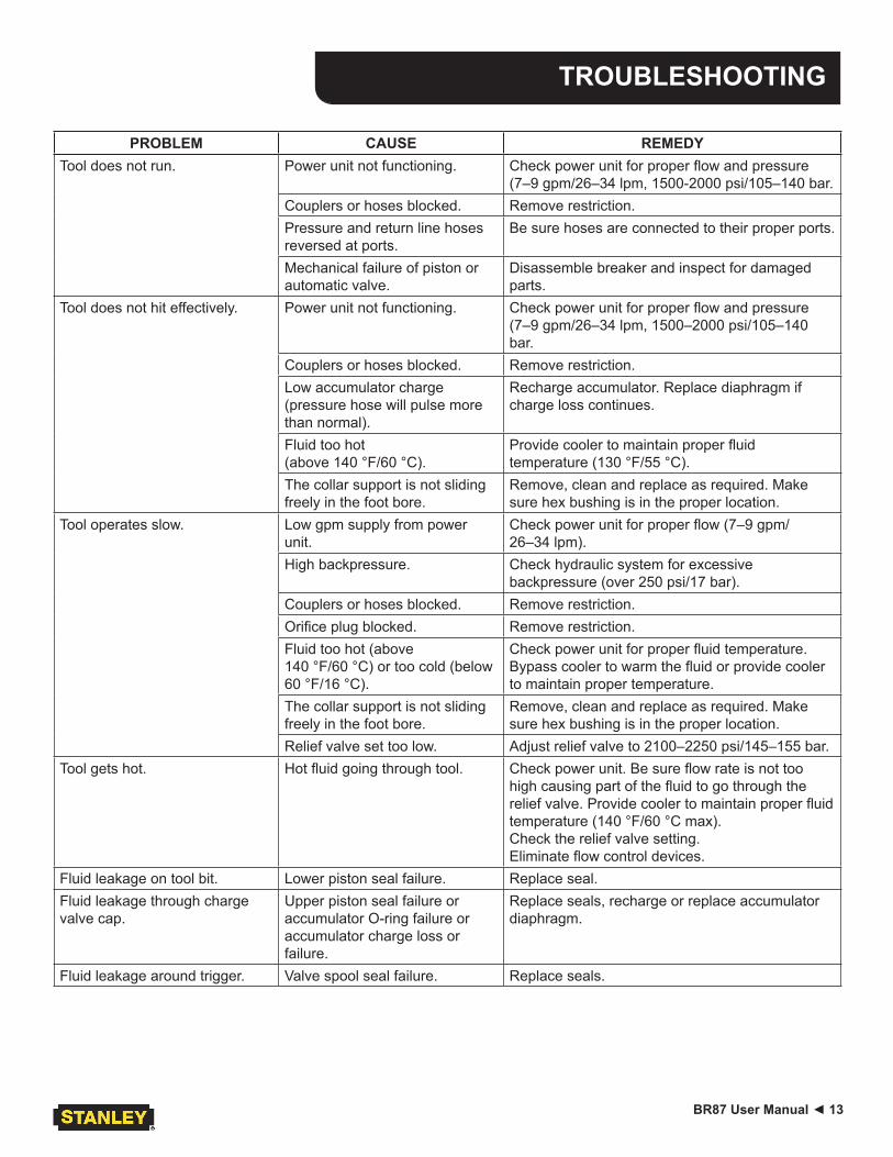
TROUBLESHOOTING
PROBLEM CAUSE REMEDYTool does not run. Power unit not functioning. Check power unit for proper flow and pressure
(7–9 gpm/26–34 lpm, 1500-2000 psi/105–140 bar.Couplers or hoses blocked. Remove restriction.Pressure and return line hoses reversed at ports.
Be sure hoses are connected to their proper ports.
Mechanical failure of piston or automatic valve.
Disassemble breaker and inspect for damaged parts.
Tool does not hit effectively. Power unit not functioning. Check power unit for proper flow and pressure (7–9 gpm/26–34 lpm, 1500–2000 psi/105–140 bar.
Couplers or hoses blocked. Remove restriction.Low accumulator charge (pressure hose will pulse more than normal).
Recharge accumulator. Replace diaphragm if charge loss continues.
Fluid too hot (above 140 °F/60 °C).
Provide cooler to maintain proper fluid temperature (130 °F/55 °C).
The collar support is not sliding freely in the foot bore.
Remove, clean and replace as required. Make sure hex bushing is in the proper location.
Tool operates slow. Low gpm supply from power unit.
Check power unit for proper flow (7–9 gpm/26–34 lpm).
High backpressure. Check hydraulic system for excessive backpressure (over 250 psi/17 bar).
Couplers or hoses blocked. Remove restriction.Orifice plug blocked. Remove restriction.Fluid too hot (above 140 °F/60 °C) or too cold (below 60 °F/16 °C).
Check power unit for proper fluid temperature. Bypass cooler to warm the fluid or provide cooler to maintain proper temperature.
The collar support is not sliding freely in the foot bore.
Remove, clean and replace as required. Make sure hex bushing is in the proper location.
Relief valve set too low. Adjust relief valve to 2100–2250 psi/145–155 bar.Tool gets hot. Hot fluid going through tool. Check power unit. Be sure flow rate is not too
high causing part of the fluid to go through the relief valve. Provide cooler to maintain proper fluid temperature (140 °F/60 °C max). Check the relief valve setting.Eliminate flow control devices.
Fluid leakage on tool bit. Lower piston seal failure. Replace seal.Fluid leakage through charge valve cap.
Upper piston seal failure or accumulator O-ring failure or accumulator charge loss or failure.
Replace seals, recharge or replace accumulator diaphragm.
Fluid leakage around trigger. Valve spool seal failure. Replace seals.
14 ► BR87 User Manual
CHARGING THE ACCUMULATOR
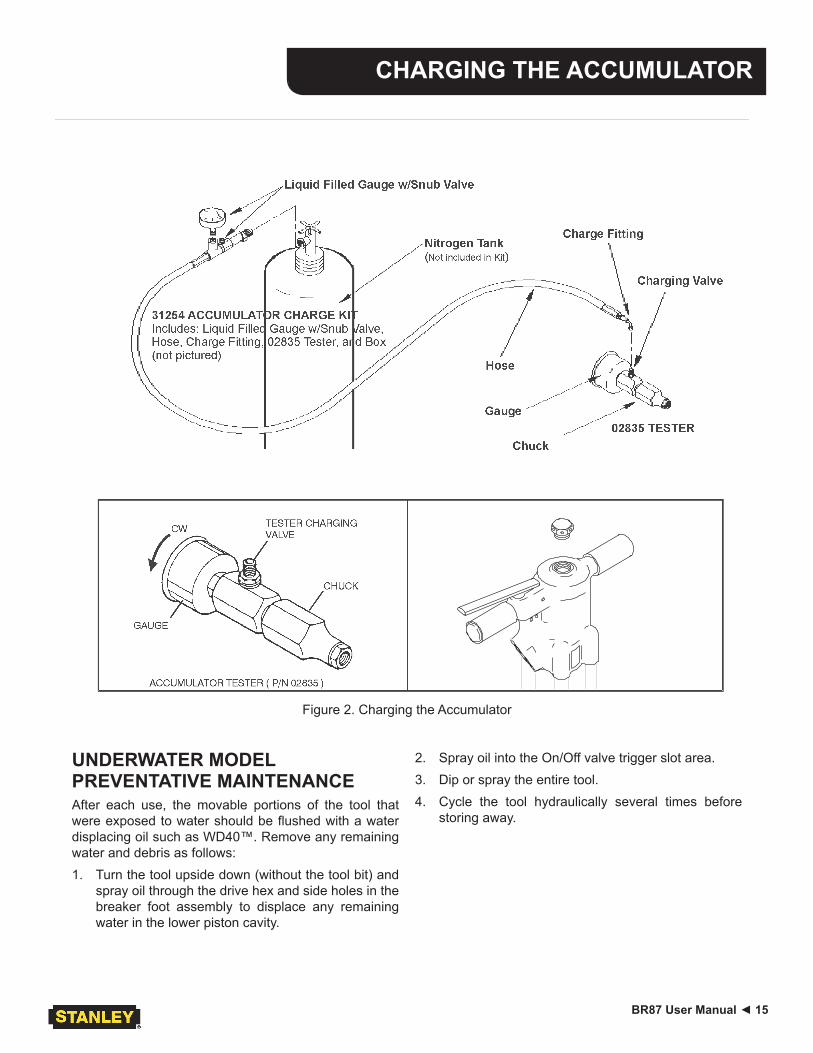
ACCUMULATOR TESTING PROCEDURE To check or charge the accumulator the following equip-ment is required:31254 Charge Kit: which includes the following.• Accumulator Tester (Part Number 02835)• Charging Assembly (P/N 15304)
(P/N 15304 includes a liquid filled gauge with snub valve, hose and fittings.)
• NITROGEN bottle with an 1000 psi/70 bar minimum charge. (Not included in 31254 Charge Kit.)
1.
CAUTION
This assembly contains nitrogen under pressure
Remove the valve cap assembly from the breaker.2. Remove the protective cap and loosen the 5/8-inch
hex locking nut on the tool charging valve 1-1/2 turns.
3. Holding the chuck end of Accumulator Tester (P/N 02835) turn the gauge fully counterclockwise to en-sure that the stem inside the chuck is completely retracted.
4. Thread the tester onto the accumulator charg-ing valve. Do not advance the gauge-end into the chuck-end. Turn as a unit. Seat the chuck on the accumulator charging valve and hand tighten only.
5. Advance the valve stem of the tester by turning the gauge-end clockwise until a pressure is read on the gauge (charge pressure should be 700-900 psi/48-62 bar).
6. If pressure is OK unscrew the gauge-end from the chuck to retract the stem, then unscrew the entire tester assembly from the accumulator charging valve. If pressure is low, charge the accumulator as described in the following paragraph.
7. Tighten the 5/8-inch hex locking nut on the tool charging valve. Be careful not to overtighten. Install the protective cap and valve cap assembly.
ACCUMULATOR CHARGING1. Perform steps 1 through 4 of the accumulator test-
ing procedure above.2. Connect the chuck of the charging assembly to the
charging valve on the accumulator tester or, if pre-ferred, remove the tester from the charging valve and connect the charging assembly chuck directly to the charging valve.
3. Adjust the regulator to the charging pressure of 800 psi/55 bar.
NOTE: It may be necessary to set the gauge at 850-900 psi/59-62 bar to overcome any pressure drop through the charging system.4. Open the valve on the charging assembly hose.5. When the accumulator is fully charged close the
valve on the charging assembly hose and remove the charging assembly chuck from the accumulator tester or tool charging valve.If the accumulator tester has been used, be sure to turn the gauge-end fully counterclockwise before re-moving the tester from the charging valve of the tool.
6. Tighten the 5/8-inch hex locking nut on the tool charging valve and replace the protective cap.
7. Replace the valve cap assembly.
GENERAL SERVICE NOTES1. If the breaker is repainted after servicing, be sure to
mask off the vent in the valve cap assembly. Do not allow paint to enter the IN and OUT ports or the bore of the foot assembly.
2. If the handle grips need to be replaced.a. Remove the old grips and clean the handle.b. Wash the new grips and the handle clean and
dry, simply push or drive the grips on. DO NOT lubricate the parts. The grips will not be secure on the handle if any grease or oil is used.
BR87 User Manual ◄ 15
CHARGING THE ACCUMULATOR
UNDERWATER MODEL PREVENTATIVE MAINTENANCEAfter each use, the movable portions of the tool that were exposed to water should be flushed with a water displacing oil such as WD40™. Remove any remaining water and debris as follows:1. Turn the tool upside down (without the tool bit) and
spray oil through the drive hex and side holes in the breaker foot assembly to displace any remaining water in the lower piston cavity.
2. Spray oil into the On/Off valve trigger slot area.3. Dip or spray the entire tool.4. Cycle the tool hydraulically several times before
storing away.
Figure 2. Charging the Accumulator
16 ► BR87 User Manual
SPECIFICATIONS
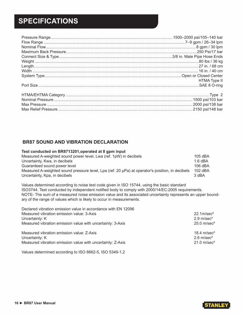
Pressure Range.............................................................................................................. 1500–2000 psi/105–140 barFlow Range ............................................................................................................................... 7–9 gpm / 26–34 lpmNominal Flow ....................................................................................................................................... 8 gpm / 30 lpmMaximum Back Pressure......................................................................................................................250 Psi/17 barConnect Size & Type ......................................................................................................3/8 in. Male Pipe Hose EndsWeight ....................................................................................................................................................80 lbs / 36 kgLength.................................................................................................................................................... 27 in. / 68 cmWidth ..................................................................................................................................................... 16 in. / 40 cmSystem Type ...........................................................................................................................Open or Closed Center
HTMA Type IIPort Size .................................................................................................................................................SAE 8 O-ring
HTMA/EHTMA Category ................................................................................................................................. Type 2Nominal Pressure ............................................................................................................................. 1500 psi/103 barMax Pressure ................................................................................................................................... 2000 psi/138 barMax Relief Pressure ......................................................................................................................... 2150 psi/148 bar
Test conducted on BR8713201,operated at 8 gpm input Measured A-weighted sound power level, Lwa (ref. 1pW) in decibels 105 dBAUncertainty, Kwa, in decibels 1.6 dBAGuaranteed sound power level 106 dBAMeasured A-weighted sound pressure level, Lpa (ref. 20 µPa) at operator's position, in decibels 102 dBAUncertainty, Kpa, in decibels 3 dBA
Values determined according to noise test code given in ISO 15744, using the basic standard ISO3744. Test conducted by independent notified body to comply with 2000/14/EC:2005 requirements. NOTE- The sum of a measured noise emission value and its associated uncertainty represents an upper bound-ary of the range of values which is likely to occur in measurements. Declared vibration emission value in accordance with EN 12096 Measured vibration emission value: 3-Axis 22.1m/sec²Uncertainty: K 2.9 m/sec²Measured vibration emission value with uncertainty: 3-Axis 25.0 m/sec²
Measured vibration emission value: Z-Axis 18.4 m/sec²Uncertainty: K 2.6 m/sec²Measured vibration emission value with uncertainty: Z-Axis 21.0 m/sec²
Values determined according to ISO 8662-5, ISO 5349-1,2
BR87 SOUND AND VIBRATION DECLARATION
BR87 User Manual ◄ 17
ACCESSORIES
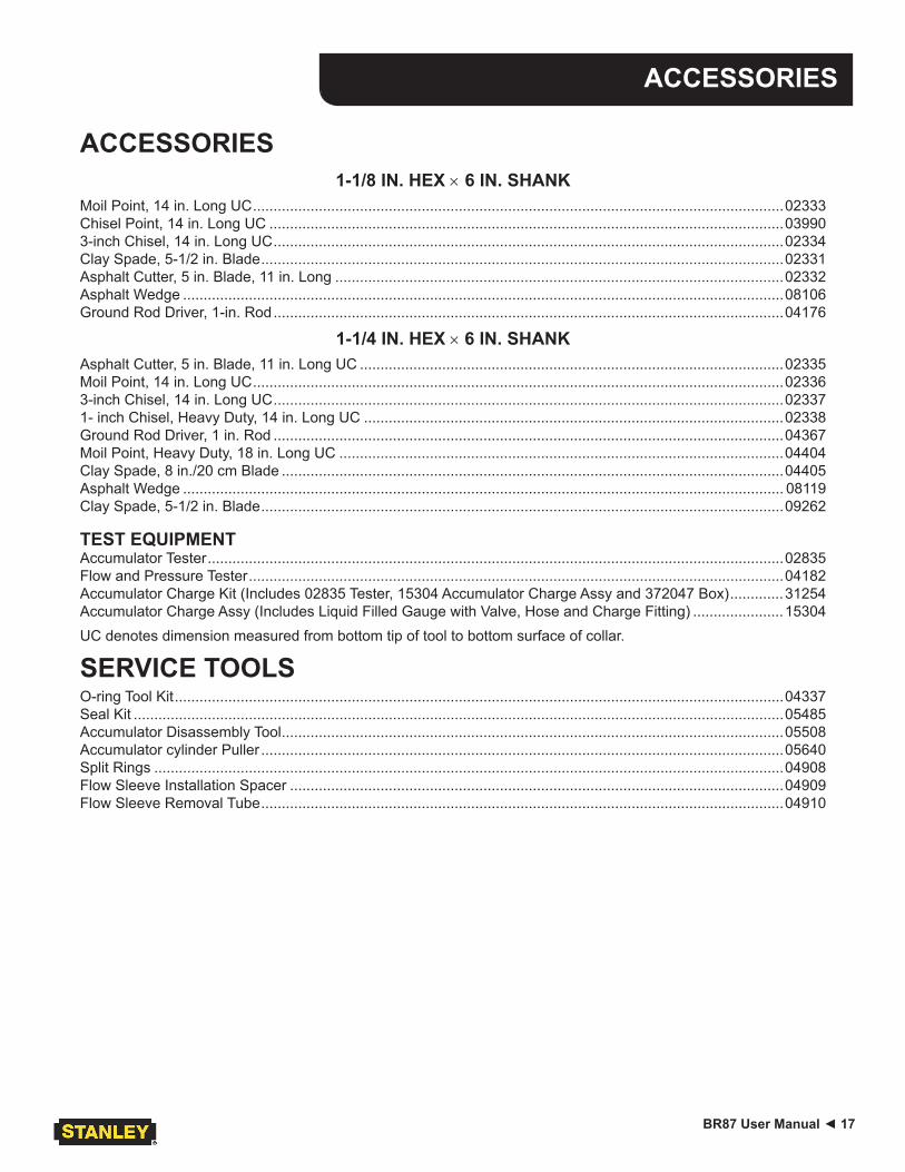
ACCESSORIES1-1/8 IN. HEX × 6 IN. SHANK
Moil Point, 14 in. Long UC .................................................................................................................................02333Chisel Point, 14 in. Long UC .............................................................................................................................039903-inch Chisel, 14 in. Long UC ............................................................................................................................02334Clay Spade, 5-1/2 in. Blade ...............................................................................................................................02331Asphalt Cutter, 5 in. Blade, 11 in. Long .............................................................................................................02332Asphalt Wedge ..................................................................................................................................................08106Ground Rod Driver, 1-in. Rod ............................................................................................................................04176
1-1/4 IN. HEX × 6 IN. SHANKAsphalt Cutter, 5 in. Blade, 11 in. Long UC .......................................................................................................02335Moil Point, 14 in. Long UC .................................................................................................................................023363-inch Chisel, 14 in. Long UC ............................................................................................................................023371- inch Chisel, Heavy Duty, 14 in. Long UC ......................................................................................................02338Ground Rod Driver, 1 in. Rod ............................................................................................................................04367Moil Point, Heavy Duty, 18 in. Long UC ............................................................................................................04404Clay Spade, 8 in./20 cm Blade ..........................................................................................................................04405Asphalt Wedge .................................................................................................................................................. 08119Clay Spade, 5-1/2 in. Blade ...............................................................................................................................09262
TEST EQUIPMENTAccumulator Tester ............................................................................................................................................02835Flow and Pressure Tester ..................................................................................................................................04182Accumulator Charge Kit (Includes 02835 Tester, 15304 Accumulator Charge Assy and 372047 Box) .............31254Accumulator Charge Assy (Includes Liquid Filled Gauge with Valve, Hose and Charge Fitting) ......................15304UC denotes dimension measured from bottom tip of tool to bottom surface of collar.
SERVICE TOOLSO-ring Tool Kit ....................................................................................................................................................04337Seal Kit ..............................................................................................................................................................05485Accumulator Disassembly Tool ..........................................................................................................................05508Accumulator cylinder Puller ...............................................................................................................................05640Split Rings .........................................................................................................................................................04908Flow Sleeve Installation Spacer ........................................................................................................................04909Flow Sleeve Removal Tube ...............................................................................................................................04910
18 ► BR87 User Manual
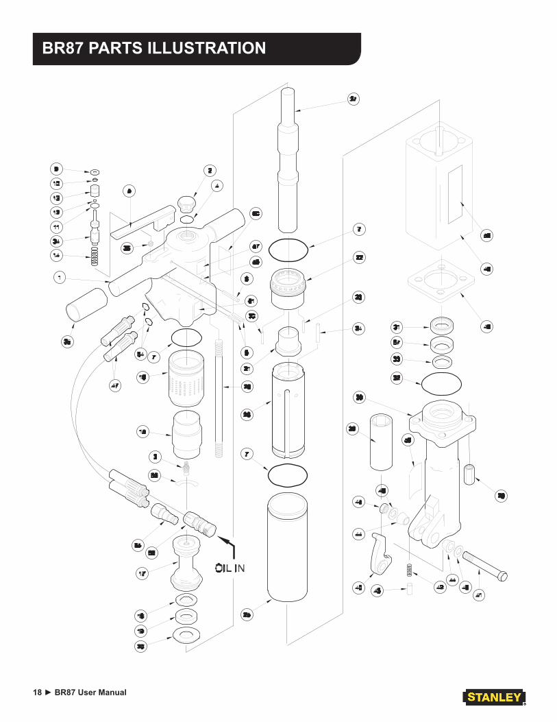
BR87 PARTS ILLUSTRATION
BR87 User Manual ◄ 19
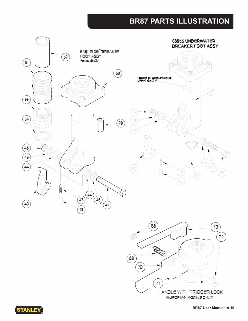
BR87 PARTS ILLUSTRATION
20 ► BR87 User Manual
BR87 PARTS LIST
Item No.
Part No. Qty Description
1 06185 1 HANDLE ASSY (INCL ITEM 35)11435 1 BREAKER HANDLE
(TRIGGER LOCK MODELS ONLY)2 04050 1 VALVE CAP ASSY3 04051 1 CHARGING VALVE4 04052 1 O-RING5 04053
114341 TRIGGER
TRIGGER (TRIGGER LOCK MODELS ONLY)6 00844 1 SPIROL PIN7 04054 3 O-RING8 22891 2 SPIROL PIN, 3/16 × 1-5/89 04055 1 WASHER10 04056 1 ROD WIPER11 00293 1 O-RING12 01362 1 O-RING13 04057 1 BUSHING14 04058 1 SPRING15 04059 1 ACCUMULATOR DIAPHRAGM16 04060 1 ACCUMULATOR CYLINDER17 05309 1 ACCUMULATOR CHAMBER ASSY
06889 1 ACCUMULATOR ASSEMBLY(INCL ITEMS 3, 7, 15–19)
18 05301 1 BACK-UP WASHER19 05307 1 CUP SEAL20 04064 1 WASHER21 04065 1 AUTOMATIC VALVE22 04066 1 AUTOMATIC VALVE BODY23 04571 2 PUSH PIN, 3/16 × 1-1/424 04067 4 PUSH PIN, 5/16 × 225 04068 1 FLOW SLEEVE TUBE26 04069 1 FLOW SLEEVE27 16812 1 PISTON28 04071 4 SIDE ROD29 04075 4 SIDE ROD NUT30 07890 1 ROLL PIN, 3/16 × 1-1/231 34127 1 CUP SEAL32 04073 1 O-RING33 04074 1 ROD WIPER34 04077 1 VALVE SPOOL, OC35 02494 2 HANDLE GRIP36 05465 1 ORIFICE PLUG37 05466
05467
1 FOOT ASSY 1-1/8 HEX (INCL ITEMS 31–33 & 38–46 & 67)FOOT ASSY 1-1/4 HEX (INCL ITEMS 31–33 & 38–46 & 67)
38 05484 1 FOOT ASSY (INCL ITEMS 33-67)07523 1 EASI-RIDETM FOOT ASSY 1-1/8 HEX
(INCL ITEMS 33, 40–46 & 51–55)07486 1 EASI-RIDETM FOOT ASSY 1-1/4 HEX
(INCL ITEMS 33, 40–46 & 51–55)39 04081
045971 HEX BUSHING, 1-1/8 HEX
HEX BUSHING, 1-1/4 HEX40 01837 1 LATCH41 04983 1 BOLT42 01744 1 SPRING43 01745
08411
1 DETENT, 1.000 OAL (SERIAL NO. 1707 AND BELOW)DETENT, 1.250 OAL (SERIAL NO. 1708 AND ABOVE)
Item No.
Part No. Qty Description
44 01269 2 RUBBER SLEEVE, 1.00045 04984 1 STOP NUT46 04985 2 SPRING WASHER47 09546 2 PIGTAIL HOSE ASSY48 05265 1 FLOW SLEEVE HOUSING49 24666 1 ELASTOMETRIC SPACER51 07515 1 SPRING52 07517
075181 HEX BUSHING, 1-1/8
HEX BUSHING, 1-1/404081 1 HEX BUSHING, 1-1/8 U/W ONLY
53 11614 1 BREAKER FOOT ASSY08855 1 BREAKER FOOT ASSY U/W ONLY
(INCL ITEMS 31–33, 40–46, 52, & 67)54 07522 1 RETAINING RING55 08115
08116
1 COLLAR SUPPORT ASSY 1-1/8 W/WEAR RINGSCOLLAR SUPPORT ASSY 1-1/4 W/WEAR RINGS
56 0789228381
1 NAMEPLATE DECALNAMEPLATE DECAL (BR8713201 & BR8717201 ONLY)
57 28322 1 CE DECAL58 11207 1 CIRCUIT TYPE “D” DECAL59 11208 1 HEX SHANK LENGTH DECAL60 72786 1 GUARNTEED SOUND POWER LEVEL DECAL61 28409 1 COMPOSITE DECAL62 — — NO ITEM63 10180 1 CAUTION DECAL64 01605 2 O-RING (INCL WITH ITEM 47)65 03973 1 FLUSH FACE COUPLER, MALE66 03972 1 FLUSH FACE COUPLER, FEMALE
03971 1 COUPLER SET67 05464 1 SEAL INSERT68 01003 1 BUTTON69 11430 1 SPRING70 11435 1 HANDLE71 11431 1 LOCK PIN72 11432 1 KEY73 11434 1 TRIGGER
SEAL KIT PART NUMBER 05485
Part No. Qty Description
00293 1 O-RING00678 1 O-RING01362 1 O-RING01605 2 O-RING04052 1 O-RING04054 3 O-RING04056 1 ROD WIPER04073 1 O-RING04074 1 ROD WIPER05307 1 CUP SEAL05641 1 O-RING34127 1 CUP SEAL

Stanley Hydraulic Tools3810 SE Naef Road
Milwaukie, Oregon 97267-5698 USA(503) 659-5660 / Fax (503) 652-1780
www.stanleyhydraulic.com
IMPORTANT
To fill out a Product Warranty Recording form, and for information on your warranty, visit Stanleyhydraulic.com and select the Warranty tab.
(NOTE: The warranty recording form must be submitted to validate the warranty).