Embed Size (px)
Citation preview
1
Displacement Ventilation DESIGN GUIDE
w w w. p r i c e - h v a c . c o m
Displacement VentilationSECTION J


© Copyright E.H. Price Limited 2007. All Metric dimensions ( ) are soft conversion. Imperial dimensions are converted to metric and rounded to the nearest millimeter. J-3
DIS
PLA
CE
ME
NT
vE
NT
ILA
TIO
N
Loading Within the Space ...........................................J24 – J25 Loads ...................................................................................... J24 Sensible and Latent Loads ..................................................... J25 Diffuser Types ................................................................J26 – J27
Diffuser Layout and Location ............................................... J28
DV Supply Air Methods ......................................................... J29
Component Selection and Installation ............................. J29
Air Volume Calculations .............................................J30 – J31
Design Procedure ..................................................................... J31
Design Examples ............................................................J32 - J37 Small Office Example ................................................. J32 – J34 Boardroom Example ....................................................J35 – J37
Special Applications Supplement .............................J38 - J52
Displacement Ventilation for Industrial Applications....J39 Machine Shop Example ...............................................J40 – J43 Displacement ventilation and Schools .......................J44 – J45 Classroom Example .....................................................J46 – J48
Displacement ventilation and Healthcare...................J49 – J51
References ................................................................................ J52
Displacement Ventilation Introduction .................... J8 - J10 Typical Applications ................................................................ J9 Terminology ........................................................................... J10
Displacement Ventilation Characteristics ............ J11 - J14 Thermal Plume .........................................................................J11 Stratification Height .................................................................J11 Room Airflow Pattern .............................................................. J12 Diffuser Air Flow Pattern ......................................................... J13 Contaminant Distribution ....................................................... J13 Temperature Distribution ....................................................... J14 Location of Returns ................................................................. J14
Thermal Comfort ........................................................... J15 – J16
Ventilation Effectiveness ....................................................... J17
Heating with Displacement Ventilation ............................. J18
Humidity Control ........................................................... J19 – J20 Design Suggestions ............................................................... J19 Direct Expansion Rooftop Units ............................................. J19 Dehumidification and Heat Recovery ......................... J19 – J20
Acoustics ........................................................................ J21 – J22
Designing with AHUs and RTUs .......................................... J23
ContentsDisplacement Ventilation
Price Industries works hard to promote the use of sustainable building materials and innovative air distribution technologies to improve the air quality and environment integrity in the built environment. Price has a long history of designing and promoting products systems that are energy efficient and ideal for use in “Green Building” designs. Price is committed to the continual introduction of new products and systems that further the goals outlined by the USGBC.
Price has partnered with Krantz Products USA Inc., North American Distributor for Krantz, the world leader in displacement ventilation diffusers, to offer a complete system for displacement ventilation distribution. The Krantz Komponenten® industrial diffusers have been the preferred specification for industrial applications since Krantz Komponenten® first pioneered the North American market. Krantz
Komponenten® diffusers are offered to the U.S. and Canadian HvAC markets exclusively through Price.

J-4 All Metric dimensions ( ) are soft conversion. © Copyright E.H. Price Limited 2007. Imperial dimensions are converted to metric and rounded to the nearest millimeter.
DIS
PLA
CE
ME
NT
vE
NT
ILA
TIO
N
This document is intended to provide answers to common questions as well as provide some guidance for working though the most common issues when designing an Displacement ventilation system. Throughout the document you will find helpful hints as well as Green Tips, Control Tips and Product Tips, an example of which is shown below.
Green Tip Green Tips provide useful insight into some opportunities for making design decisions which might help in designing a sustainable building. Some pointers are provided for both the LEED® and the Green Globes® rating systems.
Control TipControl Tips are provided to maximize the understanding of all of the control opportunities and issues with Displacement ventilation systems. In some cases these will help reduce control complexity or optimize control effectiveness.
Product Tip Product Tips provide a link between the design guide section and the product section to assist the design engineer in selecting product with the recommended characteristics.
Displacement ventilationDesign Guide
About this Design Guide

© Copyright E.H. Price Limited 2007. All Metric dimensions ( ) are soft conversion. Imperial dimensions are converted to metric and rounded to the nearest millimeter. J-5
DIS
PLA
CE
ME
NT
vE
NT
ILA
TIO
N
Displacement Ventilation Introduction
Figure 1: Mixing (Dilution) VentilationOverviewAirflow in ventilated spaces generally can be classified by two different types; mixing (or dilution) ventilation and displacement ventilation. Mixing ventilation systems (Figure 1) generally supply air in a manner such that the entire room volume is fully mixed. The cool supply air exits the outlet at a high velocity, inducing room air to provide mixing and temperature equalization. Since the entire room is fully mixed, temperature variations throughout the space are small while the contaminant concentration is uniform throughout the zone.
Displacement ventilation systems (Figure 2) introduce air into the space at low velocities which causes minimal induction and mixing. Displacement outlets may be located almost anywhere within the room, but have been traditionally located at or near floor level. The system utilizes buoyancy forces, generated by heat sources such as people, lighting, computers, electrical equipment, etc. in a room to remove contaminants and heat from the occupied zone. By so doing, the air quality in the occupied zone is generally superior to that achieved with mixing ventilation.
ConceptDisplacement ventilation presents an opportunity to improve both the thermal comfort and indoor air quality (IAQ) of the occupied space. Displacement ventilation takes advantage of the difference in air temperature and density between an upper contaminated zone and a lower clean zone. Cool air is supplied at low velocity into the lower zone. Convection from heat sources creates vertical air motion into the upper zone where high level return outlets extract the air as illustrated in Figure 3. In most cases, these convection heat sources are also the contamination sources, i.e. people or equipment, thereby carrying the contaminants up to the upper zone, away from the occupants.
Since the conditioned air is supplied directly into the occupied space, supply air temperatures must be higher than mixing systems (usually above 63 degrees F) to avoid creating uncomfortable drafts. By introducing air at elevated supply air temperatures and low outlet velocity a high level of thermal comfort can be achieved with displacement ventilation.
Figure 2: Displacement Ventilation
Displacement ventilation Design Guide
Figure 3: Displacement Flow Characteristics

J-6 All Metric dimensions ( ) are soft conversion. © Copyright E.H. Price Limited 2007. Imperial dimensions are converted to metric and rounded to the nearest millimeter.
DIS
PLA
CE
ME
NT
vE
NT
ILA
TIO
N
Displacement ventilationDesign Guide
Displacement Ventilation Introduction
Benefits
1. Flexibility – as loads change within the space, a displacement system will be able to compensate. For example, if the space was designed to have a fairly even load distribution and now has the loads concentrated to one side, the system is able to compensate as the buoyant forces drive supply system and will draw the air towards the loads.
2. IAQ – Because fresh supply air is pooling at the floor level, personal thermal plumes draw fresh air up the body. All of the warm and polluted air is extracted at the high return. When properly designed, there should always be a greater amount of fresh air in the breathing zone when compared to a conventional dilution system.
3. Both the LEED® and Green Globes green building rating systems have credits that are applicable to displacement ventilation systems. See the Green Tips for further information.
4. Energy Savings –
• Thelowerpressuredropassociatedwithdisplacementventilationoutlets,mayallowareductioninfanenergywiththeselection of a smaller fan components.
• Economizeroperatinghourscanbeincreasedtotakeadvantageoffreecoolingbecausesupplyairtemperaturesarehigherthan with overhead air distribution systems.
• Chillerefficiencymaybeincreasedwhenthesystemisnotdehumidifying,asthereisalowersupplyairtemperatureandhigher return air temperature.
Typical Applications
• Displacement ventilation is an effective method of obtaininggood air quality and thermal comfort in the occupied space. Spaces where displacement ventilation has been successfully used are:
- Schools - Theaters
- Classrooms - Casinos
- Hospitals - Restaurants
- Dining Rooms - Meeting Rooms
- Conference Rooms - Supermarkets
- Industrial Spaces
• Displacement ventilation is usually a good choice in the following cases:
- Where the contaminants are warmer and/or lighter than the room air.
- Where the supply air is cooler than the room air.
- Where the room heights are 9 feet or more.
- Where low noise levels are desired.
• OverheadAirDistributionmaybeabetterchoicethandisplacement ventilation in the following cases:
- Where ceiling heights are below 8 feet.
- Where disturbances to room airflow are strong.
- Where contaminants are colder and/or denser than the ambient air.
- Where cooling loads are high and radiant cooling is not an option.
Figure 4: Classroom Application
Figure 5: High Ceiling Application

© Copyright E.H. Price Limited 2007. All Metric dimensions ( ) are soft conversion. Imperial dimensions are converted to metric and rounded to the nearest millimeter. J-7
DIS
PLA
CE
ME
NT
vE
NT
ILA
TIO
N
Displacement ventilationDesign Guide
Terminology
Adjacent Zone
The adjacent zone is defined as the distance from the diffuser face to a point where the velocity of the airstream is reduced below to 40 FPM measured 1” above the floor.
Buoyancy
The vertical force exerted on a volume of air that has a density lower than the ambient air.
Breathing Zone
The estimated height at which occupants will inhale the surrounding air.
CFD
Computational Fluid Dynamics. The analysis of a space utilizing computers to simulate fluid motion. An example of output from a CFD analysis is shown in Figure 8.
Displacement Ventilation
Room ventilation created by room air displacement, by introducing air at low level in a space at a lower air temperature than the room air.
Draft
Unwanted local cooling of a body caused by movement of air.
Draft Temperature
The effective temperature based on the temperature and velocity of the supply air causing discomfort.
Green Globes®
A sustainable building rating system from the Green Building Initiative (GBI).
IAQ
Indoor Air Quality.
LEED®
Leadership in Energy and Environmental Design. A sustainable building rating program from the US Green Building Council.
Length, Adjacent Zone
The Length of the adjacent zone is the length from the diffuser face to a specified velocity, typically 40 FPM, refer to Figure 6.
Mixed Ventilation
Air diffusion where the mixing of supply and room air is intended.
Occupied Zone
An imaginary box in the room defined as 6 feet above the floor and not less than 24 inches from the walls.
L
WL
Figure 7
Figure 8
Percent Dissatisfied (PD)
ASHRAE defines the percent dissatisfied as the percentage of people predicted to be dissatisfied with their environment due to draft.
Predicted Mean Vote (PMV)
The Predicted Mean vote, PMv, is an index that predicts the mean value of the votes of a large group of persons in relation to a scale defined by ASHRAE [ASHRAE Standard 55 2004]
Predicted Percentage of Dissatisfied (PPD)
ASHRAE defines the predicted percentage of dissatisfied as “an index that establishes a quantitative prediction of the percentage of thermally dissatisfied people determined from PMv.” In real terms it is a measure of the thermal comfort performance in a space.
Thermal Plume
The air current rising from a hot body.
Stratification
When the temperature of the space varies with height.
Upper Zone
The space above the occupied zone.
Ventilation Effectiveness
The ratio of contaminants in the exhaust to the contaminates at the breathing level. An indication of how well a space is extracting contaminates, and an indication of IAQ.
Width, Adjacent Zone
The width of the adjacent zone is the width from the diffuser face to a specified velocity, typically 40 FPM, refer to Figure 7.
L
WL
Figure 6

J-8 All Metric dimensions ( ) are soft conversion. © Copyright E.H. Price Limited 2007. Imperial dimensions are converted to metric and rounded to the nearest millimeter.
DIS
PLA
CE
ME
NT
vE
NT
ILA
TIO
N
Displacement ventilationDesign Guide
Displacement Ventilation Characteristics
Thermal Plume
As heat sources transfer heat to the surrounding air, the air becomes more buoyant. This causes air to rise in the space and to be replaced by air from the side or below, otherwise known as natural convection. As a thermal plume rises above the heat source, it entrains surrounding air and increases in size and volume as it loses momentum, moving away from the heat source, as depicted in Figure 9. The maximum height to which a plume will rise is dependent on the heat source strength, as the initial momentum of the plume will increase. Also, a room with more stratification will reduce the relative density of the plu me and, as a result, the height to which the plume will rise.
The thermal plume generated from a point source acts differently than a thermal plume generated from large objects in the space. For example, a cylinder produces a boundary layer and the convective thermal plume takes a different shape. A point source type expansion of the thermal plume is still present, but at an altered height, and with the thermal plume boundary layer included, shown in Figure 10. The cylinder is a better approximation of an occupant in the space than a point source.
Stratification Height
In Figure 11, q0 represents the supply airflow into the room from a low side-wall diffuser, q1 is the upward moving airflow contained in thermal plumes that form above heat sources, and q2 is the downward moving airflow resulting from cool surfaces. In terms of this simplified configuration, the stratification height will occur at a height (Yst) where the net upward moving flow, q1-q2, equals q0. Clearly, an important objective in designing and operating a displacement ventilation system is to maintain the stratification height near the top of the occupied zone (1.8m [6 ft]). If the building occupants are in a seated work position, a lower stratification height (e.g. 1.2m [4ft]) may be acceptable.
Figure 9: Thermal Plume, [Source: ASHRAE Underfloor Design Guide]
Green Tip Lower stratification heights will result from reduced airflow. This saves energy from treating outdoor air as well as primary fan energy.
Figure 10: Thermal Plume of Cylinder [Source: Skistad]
Figure 11 - Stratification Height
Yst
q1
q2
q0

© Copyright E.H. Price Limited 2007. All Metric dimensions ( ) are soft conversion. Imperial dimensions are converted to metric and rounded to the nearest millimeter. J-9
DIS
PLA
CE
ME
NT
vE
NT
ILA
TIO
N
Displacement ventilationDesign Guide
Displacement Ventilation Characteristics
Figure 12: Air LayersRoom Airflow PatternAirflow patterns in a displacement ventilation system are quite different than in a mixing system. Because of the low discharge velocity of displacement outlets, the room air motion is influenced to a large degree by convection flows. The convection flows are created by heat sources such as people, equipment or warm windows, or by heat sinks such as a cold wall or window. The convection flows within the room cause the formation of horizontal air layers. The warmest air layers are near the ceiling and the coolest air layers are near the floor as depicted in Figure 12.
Room air moves horizontally across the floor due to momentum from the supply outlet and suction from thermal plumes.
vertical air movement (Figure 13) between layers is caused by stronger convection forces associated with heat sources or cold sinks. Heat sources such as people, computers, lights, etc. create a rising convection flow known as a thermal plume. The strength of the thermal plume is dependent on the power and geometry of the heat source. Depending on the strength of the thermal plume, the convection flows can rise to the ceiling or distribute at a lower height. Cold sinks such as an exterior wall or window can generate convection flows down the wall and across the floor.
Airflow Penetration
A displacement system supplying cool air through a diffuser will deliver air along the floor in a thin layer typically less than 8” in height.
The supply air spreads across the floor in a similar manner to water flowing out of a tap, filling the entire space. If obstructions such as furniture or partitions are encountered, the air will flow around and beyond the obstruction illustrated in Figure 14. Even rooms with irregular geometries can be uniformly supplied with conditioned air (Figure 15).
When the cool air meets a heat source such as a person or piece of equipment, a portion of the conditioned air is captured by the thermal plume of the heat source, while the remainder of air continues further into the room.
When designing the system to deal with the cooling demand of the space, the penetration depth of a displacement diffuser can be 26 – 30 feet from the face of the diffuser. For rooms exceeding 30 feet in length or width, diffusers on several walls would normally be required.
Figure 14: Obstruction
Diffuser
Partition
Couch
Supply Air
Figure 15: Irregular Room Geometry
Supply Air Diffuser
Green Tip Because displacement ventilation systems are gravity driven, caution must be used in sloped applications. A theater with even seating, will require less diffusers in the lower sections of the theater and more in the upper to compensate the natural movement of the air to the lower portion of the theater.
Figure 13: Vertical Air Movement
J-10 All Metric dimensions ( ) are soft conversion. © Copyright E.H. Price Limited 2007. Imperial dimensions are converted to metric and rounded to the nearest millimeter.
DIS
PLA
CE
ME
NT
vE
NT
ILA
TIO
N
Displacement ventilationDesign Guide
Displacement Ventilation Characteristics
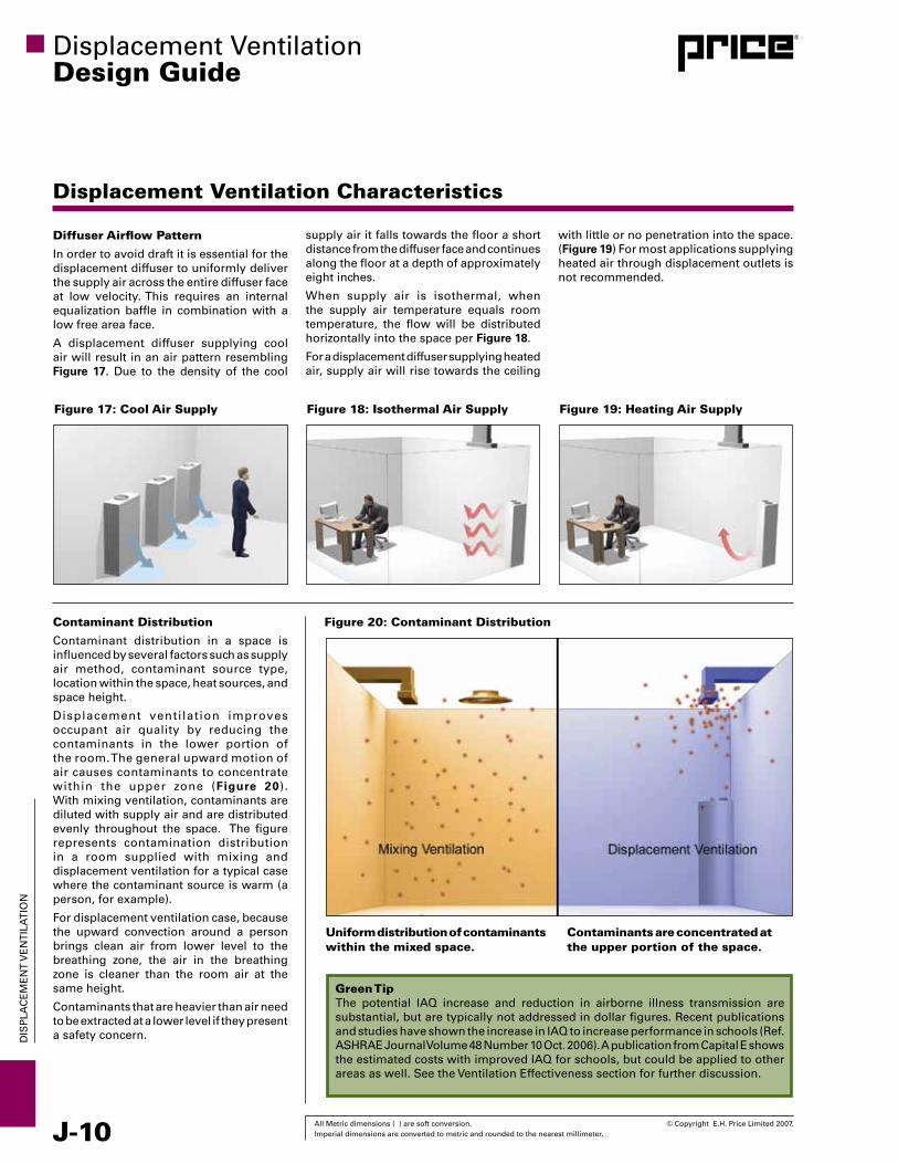
Diffuser Airflow Pattern
In order to avoid draft it is essential for the displacement diffuser to uniformly deliver the supply air across the entire diffuser face at low velocity. This requires an internal equalization baffle in combination with a low free area face.
A displacement diffuser supplying cool air will result in an air pattern resembling Figure 17. Due to the density of the cool
with little or no penetration into the space. (Figure 19) For most applications supplying heated air through displacement outlets is not recommended.
Figure 17: Cool Air Supply Figure 18: Isothermal Air Supply Figure 19: Heating Air Supply
Contaminant Distribution
Contaminant distribution in a space is influenced by several factors such as supply air method, contaminant source type, location within the space, heat sources, and space height.
Displacement ventilation improves occupant air quality by reducing the contaminants in the lower portion of the room. The general upward motion of air causes contaminants to concentrate within the upper zone (Figure 20).With mixing ventilation, contaminants are diluted with supply air and are distributed evenly throughout the space. The figure represents contamination distribution in a room supplied with mixing and displacement ventilation for a typical case where the contaminant source is warm (a person, for example).
For displacement ventilation case, because the upward convection around a person brings clean air from lower level to the breathing zone, the air in the breathing zone is cleaner than the room air at the same height.
Contaminants that are heavier than air need to be extracted at a lower level if they present a safety concern.
Figure 20: Contaminant Distribution
Uniform distribution of contaminants within the mixed space.
Contaminants are concentrated at the upper portion of the space.
Green Tip The potential IAQ increase and reduction in airborne illness transmission are substantial, but are typically not addressed in dollar figures. Recent publications and studies have shown the increase in IAQ to increase performance in schools (Ref. ASHRAE Journal volume 48 Number 10 Oct. 2006). A publication from Capital E shows the estimated costs with improved IAQ for schools, but could be applied to other areas as well. See the ventilation Effectiveness section for further discussion.
supply air it falls towards the floor a short distance from the diffuser face and continues along the floor at a depth of approximately eight inches.
When supply air is isothermal, when the supply air temperature equals room temperature, the flow will be distributed horizontally into the space per Figure 18.
For a displacement diffuser supplying heated air, supply air will rise towards the ceiling

© Copyright E.H. Price Limited 2007. All Metric dimensions ( ) are soft conversion. Imperial dimensions are converted to metric and rounded to the nearest millimeter. J-11
DIS
PLA
CE
ME
NT
vE
NT
ILA
TIO
N
Displacement ventilationDesign Guide
Displacement Ventilation Characteristics
Figure 21: Vertical Temperature GradientTemperature DistributionSince cool air is introduced at low level with a displacement ventilation system, a temperature gradient exists between the floor and ceiling level of the space. This vertical temperature gradient is known as stratification. Figure 21 illustrates a typical temperature profile for a room with displacement ventilation.
The temperature profile, or stratification, is affected by several factors; most notably the supply air volume, room cooling load, location and type of heat source and height of the space. The greater the volume of air supplied into a room, the lower the temperature differ- ence between floor and ceiling. If heat sources are located in the lower part of the room, the temperature gradient is greater in the lower part of the room and lessens in the upper part. Conversely, when heat sources are located in the upper part of the room the greatest stratification occurs near the ceiling (Figure 22).
Controlling stratification in the occupied zone is critical to maintaining occupant comfort. ASHRAE Standard 55 requires the temperature difference between the head and foot level of a standing person not to exceed 5°F.
The ASHRAE Design Guide has determined a method to calculate the head to foot temperature stratification of a displacement system based on supply air volume and load distribution. This relationship was used to develop a design procedure for displacement ventilation systems. An explanation of how the calculation method was achieved is presented on page J30. The design procedure is presented on page J31. Using this design procedure an acceptable room temperature stratification level can be achieved.
For commercial displacement ventilation systems, supply air temperatures ranging from 65-68ºF can be expected. As well, the temperature difference between return and supply in a stratified system will generally be greater than 13ºF.
Location of Returns
Returns should be located as high as possible in the space to remove as much of the stratified zone as possible, ideally at ceiling height. If the return is located below the ceiling, the air above the return may not
Figure 22: Heat Source Location
Heat Sources In Upper Zone
Heat Sources In Lower Zone
Temperature °FReference: REHVA Guidebook
64 66 68 70 72 74 76 78 80
9
8
7
6
5
4
3
2
1
be exhausted properly from the space. If the exhaust is located lower than 7 feet there may be some polluted/hot air remaining within the occupied zone. For lower ceilings it is best to place the return above the heat source in the space.
Control TipTemperature stratification above the occupied zone is not a concern, as long as the ceiling is over 8 feet. Ensure that the returns are extracting at a minimum of 9 feet to ensure stratification control.
Product TipWhere additional cooling is required, chilled ceiling systems can be used to remove additional heat from the space. For more information on chilled ceiling systems see the Radiant Systems section.

J-12 All Metric dimensions ( ) are soft conversion. © Copyright E.H. Price Limited 2007. Imperial dimensions are converted to metric and rounded to the nearest millimeter.
DIS
PLA
CE
ME
NT
vE
NT
ILA
TIO
N
Displacement ventilationDesign Guide
Thermal Comfort
Thermal ComfortASHRAE Standard 55 defines thermal comfort as a “condition of the mind which expresses satisfaction with the thermal environment”. This definition is based on the fact that each person defines what is thermally comfortable based upon their own physiological and psychological states.
To no small part, a building occupants’ preferred thermal environment is based upon what they are normally exposed to and as a result, expect to find in any space they enter. Today, most building occupants expect a narrow range of temperature, air velocity and humidity and if the environment is out of their preconceived expectations, a thermal complaint will occur.
Another issue affecting thermal comfort is the fact that when a person first enters a new thermal environment, they may not find that environment acceptable for a period of time if they have experienced different thermal conditions or different activity levels just prior to entering the space. This period of adaptation may take up to an hour before the person becomes satisfied with the new thermal environment. Unless the building is only occupied by one occupant and the occupant is in complete control of his or her thermal environment, there will always be at least one occupant who will express dissatisfaction with the building HvAC systems. As a result, ASHRAE defines the goal for the thermal environme nt as an acceptance by a substantial majority (at least 80%) of the building occupants.
Most building HvAC designers would prefer to never hear feedback from the occupants of a building that they have designed – no feedback would indicate a good design as most people will complain about being hot or cold, but rarely will a building occupant give kudos for being thermally comfortable.
The factors that must be addressed when defining conditions for human thermal comfort include:
• metabolicrate •clothinginsulation
• radianttemperature •airtemperature
• humidity •airspeed
Most designers only consider the last three, but in reality, all six are of equal importance.
ASHRAE Standard 55 defines a comfort zone that may be determined for a given range of humidity, air temperature, radiant temperature, air speed, metabolic rate, and clothing insulation. This comfort zone is typically defined in terms of a range of operative temperatures that will provide a thermal environment that a specific percentage of occupants will find acceptable. This method may be used in spaces where the occupants Met levels are within 1.0 Met to 1.3 Met and clothing has a clo value between 0.5 clo and 1.0 clo of thermal insulation. Most office spaces fall within these limitations.
Figure 22 shows the range of operative temperatures for an 80% occupant acceptance. This range of operative temperatures are based on a 10% dissatisfaction criteria for whole body (general) thermal comfort (based on the PMv – PPD index – see ASHRAE Standard 55 for a description of the PMv – PPD index) and an additional 10% dissatisfaction for local thermal comfort. Two zones are shown on these figures, one for 0.5 clo and one for 1.0 clo which is intended to be representative of when the outdoor environment is warm and cool, respectively. Figure 23 shows the effect of air velocity on the operative temperature.
Figure 22: Acceptable range of operative temperature and humidity [ASHRAE Standard 55 2004]
80%
80%
70%
60%
50%
40%
30%
20%
10% RELATIVE HUMIDITY55 60 65 70 75 80 85 90 95 10
0
DR
Y B
ULB
TE
MP
ER
AT
UR
E -
ºF
HU
MID
ITY
RA
TIO
- P
OU
ND
S M
OIS
TU
RE
PE
R P
OU
ND
DR
Y A
IR
.014
.012
.010
.006
.005
.004
.002
PMV Limit 0.5
No Recommended Lower Humidity
Limit
Upper Recommended Humidity Limit 0.012 humidity ratio
Data based on ISO 7730 and ASHRAE STD 55
1.0 Clo 0.5 Clo
Figure 23: Effect of air velocity on acceptable range of operative temperature and humidity [ASHRAE Standard 55 2004]
80%
80%
70%
60%
50%
40%
30%
20%
10% RELATIVE HUMIDITY
55 60 65 70 75 80 85 90 95 100
DR
Y B
ULB
TE
MP
ER
AT
UR
E -
ºF
HU
MID
ITY
RA
TIO
- P
OU
ND
S M
OIS
TU
RE
PE
R P
OU
ND
DR
Y A
IR
.014
.012
.010
.006
.005
.004
.002
PMV Limit 0.5
No Recommended Lower Humidity
Limit
Upper Recommended Humidity Limit 0.012 humidity ratioData based on ISO 7730
and ASHRAE STD 55
15 FPM 50 FPM
30 FPM
© Copyright E.H. Price Limited 2007. All Metric dimensions ( ) are soft conversion. Imperial dimensions are converted to metric and rounded to the nearest millimeter. J-13
DIS
PLA
CE
ME
NT
vE
NT
ILA
TIO
N
Displacement ventilationDesign Guide
Thermal Comfort
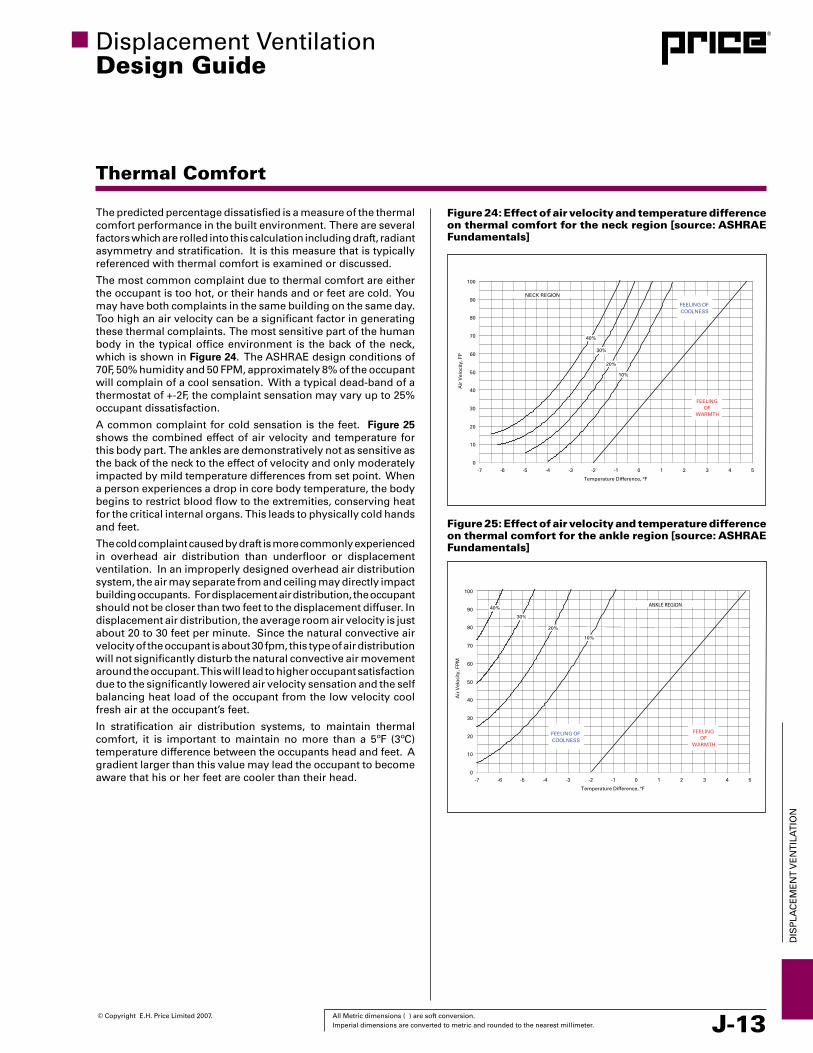
Figure 24: Effect of air velocity and temperature difference on thermal comfort for the neck region [source: ASHRAE Fundamentals]
0
10
20
30
40
50
60
70
80
90
100
-7 -6 -5 -4 -3 -2 -1 0 1 2 3 4 5
Temperature Difference, °F
Air
Vel
oci
ty, F
P
FEELING OF COOLNESS
FEELING OF
WARMTH
30%
NECK REGION
40%
20%
10%
Figure 25: Effect of air velocity and temperature difference on thermal comfort for the ankle region [source: ASHRAE Fundamentals]
0
10
20
30
40
50
60
70
80
90
100
-7 -6 -5 -4 -3 -2 -1 0 1 2 3 4 5
Temperature Difference, °F
Air
Vel
oci
ty, F
PM
FEELING OF COOLNESS
FEELING OF
WARMTH
NECK REGION
30%
40%
20%
10%
The predicted percentage dissatisfied is a measure of the thermal comfort performance in the built environment. There are several factors which are rolled into this calculation including draft, radiant asymmetry and stratification. It is this measure that is typically referenced with thermal comfort is examined or discussed.
The most common complaint due to thermal comfort are either the occupant is too hot, or their hands and or feet are cold. You may have both complaints in the same building on the same day. Too high an air velocity can be a significant factor in generating these thermal complaints. The most sensitive part of the human body in the typical office environment is the back of the neck, which is shown in Figure 24. The ASHRAE design conditions of 70F, 50% humidity and 50 FPM, approximately 8% of the occupant will complain of a cool sensation. With a typical dead-band of a thermostat of +-2F, the complaint sensation may vary up to 25% occupant dissatisfaction.
A common complaint for cold sensation is the feet. Figure 25 shows the combined effect of air velocity and temperature for this body part. The ankles are demonstratively not as sensitive as the back of the neck to the effect of velocity and only moderately impacted by mild temperature differences from set point. When a person experiences a drop in core body temperature, the body begins to restrict blood flow to the extremities, conserving heat for the critical internal organs. This leads to physically cold hands and feet.
The cold complaint caused by draft is more commonly experienced in overhead air distribution than underfloor or displacement ventilation. In an improperly designed overhead air distribution system, the air may separate from and ceiling may directly impact building occupants. For displacement air distribution, the occupant should not be closer than two feet to the displacement diffuser. In displacement air distribution, the average room air velocity is just about 20 to 30 feet per minute. Since the natural convective air velocity of the occupant is about 30 fpm, this type of air distribution will not significantly disturb the natural convective air movement around the occupant. This will lead to higher occupant satisfaction due to the significantly lowered air velocity sensation and the self balancing heat load of the occupant from the low velocity cool fresh air at the occupant’s feet.
In stratification air distribution systems, to maintain thermal comfort, it is important to maintain no more than a 5ºF (3ºC) temperature difference between the occupants head and feet. A gradient larger than this value may lead the occupant to become aware that his or her feet are cooler than their head.
ANKLE REGION
J-14 All Metric dimensions ( ) are soft conversion. © Copyright E.H. Price Limited 2007. Imperial dimensions are converted to metric and rounded to the nearest millimeter.
DIS
PLA
CE
ME
NT
vE
NT
ILA
TIO
N
Displacement ventilationDesign Guide
Ventilation Effectiveness
Ventilation Effectiveness
ventilation effectiveness is a measure of the air distribution system’s ability to remove airborne pollutants from a building space. This removal of airborne pollutants occurs through the injection of fresh, clean air through a diffuser into the space and removal of the dirtier room air through a return grille.
One measure of the ventilation effectiveness is to compare the contamination level in the breathing zone to the contamination level present in the return air grille for a zone.
Where:
ε= Cpe/Cpbz
Cpe = concentration of pollutants in the exhaust
Cpbz = concentration of pollutants at breathing level
If the zone (or room) is 100% mixed, the ventilation effectiveness, ε= 1.0, the air in the occupied breathing zone is as fresh (or dirty) as the air in at the return grille.
If ε > 1.0, the air in the occupied breathing zone is fresher (cleaner) than the return air this indicates that the pollutants are being moved by the cleaner supply air away from the occupied zone and toward the return grille.
If ε < 1.0, this indicates that the occupied breathing zone is dirtier than the return air and this lowered ventilation effectiveness is typically caused by short-circuiting of the supply air to the return grill and is considered a gross waste of pollution removal potential.
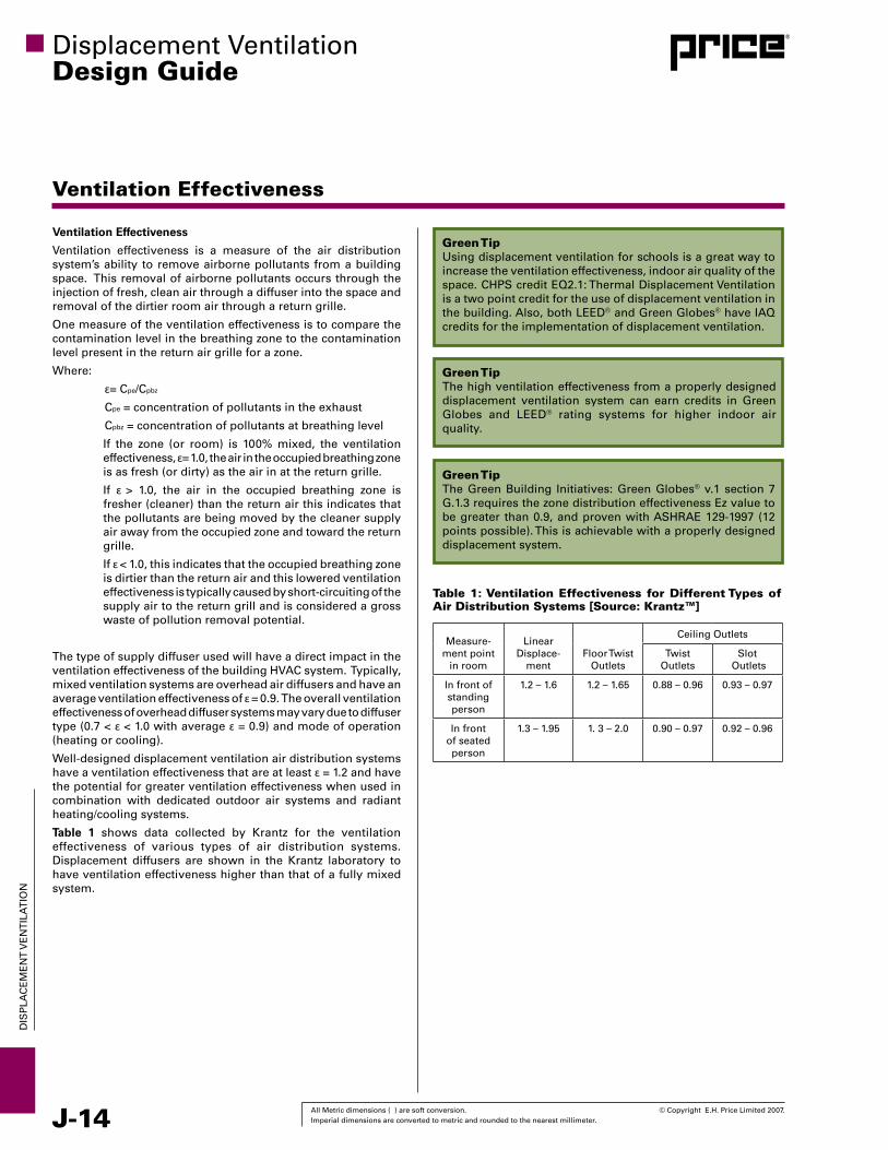
The type of supply diffuser used will have a direct impact in the ventilation effectiveness of the building HvAC system. Typically, mixed ventilation systems are overhead air diffusers and have an average ventilation effectiveness of ε = 0.9. The overall ventilation effectiveness of overhead diffuser systems may vary due to diffuser type (0.7 < ε < 1.0 with average ε = 0.9) and mode of operation (heating or cooling).
Well-designed displacement ventilation air distribution systems have a ventilation effectiveness that are at least ε = 1.2 and have the potential for greater ventilation effectiveness when used in combination with dedicated outdoor air systems and radiant heating/cooling systems.
Table 1 shows data collected by Krantz for the ventilation effectiveness of various types of air distribution systems. Displacement diffusers are shown in the Krantz laboratory to have ventilation effectiveness higher than that of a fully mixed system.
Measure-ment point
in room
Linear Displace-
mentFloor Twist
Outlets
Ceiling Outlets
Twist Outlets
Slot Outlets
In front of standing person
1.2 – 1.6 1.2 – 1.65 0.88 – 0.96 0.93 – 0.97
In front of seated person
1.3 – 1.95 1. 3 – 2.0 0.90 – 0.97 0.92 – 0.96
Table 1: Ventilation Effectiveness for Different Types of Air Distribution Systems [Source: Krantz™]
Green Tip Using displacement ventilation for schools is a great way to increase the ventilation effectiveness, indoor air quality of the space. CHPS credit EQ2.1: Thermal Displacement ventilation is a two point credit for the use of displacement ventilation in the building. Also, both LEED® and Green Globes® have IAQ credits for the implementation of displacement ventilation.
Green Tip The high ventilation effectiveness from a properly designed displacement ventilation system can earn credits in Green Globes and LEED® rating systems for higher indoor air quality.
Green Tip The Green Building Initiatives: Green Globes® v.1 section 7 G.1.3 requires the zone distribution effectiveness Ez value to be greater than 0.9, and proven with ASHRAE 129-1997 (12 points possible). This is achievable with a properly designed displacement system.
© Copyright E.H. Price Limited 2007. All Metric dimensions ( ) are soft conversion. Imperial dimensions are converted to metric and rounded to the nearest millimeter. J-15
DIS
PLA
CE
ME
NT
vE
NT
ILA
TIO
N
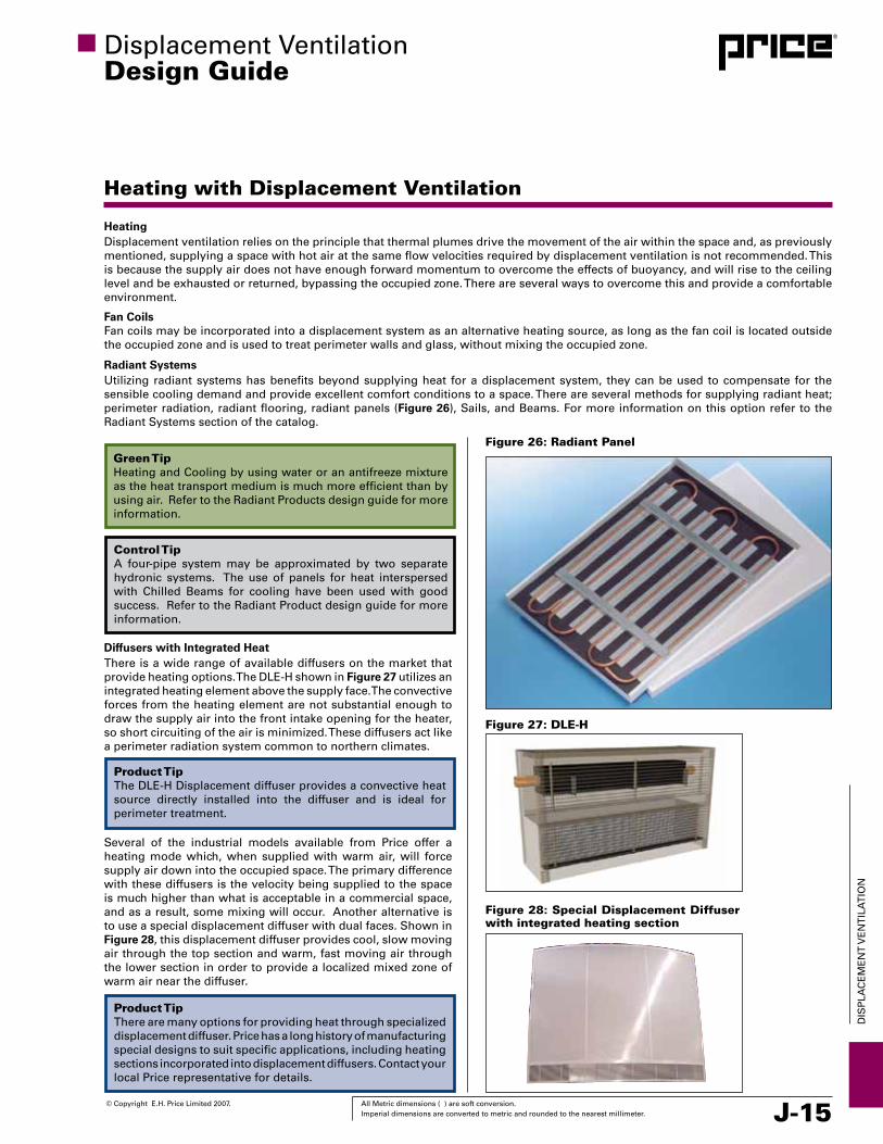
Diffusers with Integrated HeatThere is a wide range of available diffusers on the market that provide heating options. The DLE-H shown in Figure 27 utilizes an integrated heating element above the supply face. The convective forces from the heating element are not substantial enough to draw the supply air into the front intake opening for the heater, so short circuiting of the air is minimized. These diffusers act like a perimeter radiation system common to northern climates.
Several of the industrial models available from Price offer a heating mode which, when supplied with warm air, will force supply air down into the occupied space. The primary difference with these diffusers is the velocity being supplied to the space is much higher than what is acceptable in a commercial space, and as a result, some mixing will occur. Another alternative is to use a special displacement diffuser with dual faces. Shown in Figure 28, this displacement diffuser provides cool, slow moving air through the top section and warm, fast moving air through the lower section in order to provide a localized mixed zone of warm air near the diffuser.
Displacement ventilationDesign Guide
Heating with Displacement Ventilation
HeatingDisplacement ventilation relies on the principle that thermal plumes drive the movement of the air within the space and, as previously mentioned, supplying a space with hot air at the same flow velocities required by displacement ventilation is not recommended. This is because the supply air does not have enough forward momentum to overcome the effects of buoyancy, and will rise to the ceiling level and be exhausted or returned, bypassing the occupied zone. There are several ways to overcome this and provide a comfortable environment.
Fan CoilsFan coils may be incorporated into a displacement system as an alternative heating source, as long as the fan coil is located outside the occupied zone and is used to treat perimeter walls and glass, without mixing the occupied zone.
Radiant SystemsUtilizing radiant systems has benefits beyond supplying heat for a displacement system, they can be used to compensate for the sensible cooling demand and provide excellent comfort conditions to a space. There are several methods for supplying radiant heat; perimeter radiation, radiant flooring, radiant panels (Figure 26), Sails, and Beams. For more information on this option refer to the Radiant Systems section of the catalog.
Figure 26: Radiant Panel
Figure 27: DLE-H
Green Tip Heating and Cooling by using water or an antifreeze mixture as the heat transport medium is much more efficient than by using air. Refer to the Radiant Products design guide for more information.
Control TipA four-pipe system may be approximated by two separate hydronic systems. The use of panels for heat interspersed with Chilled Beams for cooling have been used with good success. Refer to the Radiant Product design guide for more information.
Product TipThe DLE-H Displacement diffuser provides a convective heat source directly installed into the diffuser and is ideal for perimeter treatment.
Product TipThere are many options for providing heat through specialized displacement diffuser. Price has a long history of manufacturing special designs to suit specific applications, including heating sections incorporated into displacement diffusers. Contact your local Price representative for details.
Figure 28: Special Displacement Diffuser with integrated heating section

J-16 All Metric dimensions ( ) are soft conversion. © Copyright E.H. Price Limited 2007. Imperial dimensions are converted to metric and rounded to the nearest millimeter.
DIS
PLA
CE
ME
NT
vE
NT
ILA
TIO
N
Displacement ventilationDesign Guide
Humidity Control
Humidity control is extremely important and exists in most climates, not just the traditional hot and humid climates. Controlling humidity is the most common question when discussing the concepts of underfloor air distribution, or displacement air distribution.
Controlling humidity means different things to different people as their personal perspectives are different. In the office environment, humidity control means limiting the upper humidity level to the guidelines of ASRHAE Standard 55 in order to provide good thermal comfort. Museums often need humidity levels to be maintained in a narrow range to slow or prevent decay in artwork and historical displays.
Temperature control is automatically part of a building HvAC equipment design, while humidity control is not always automatically included in buildings located in areas that are not considered hot and humid. If humidity control is included, it may only be to maintain a humidity level that does not exceed the recommended upper limit of ASRHAE Standard 55. In fact, most buildings experience a drift of humidity levels from hour to hour.
Building Shells Are Sources of Humidity
All buildings leak air through the building shell. In a humid climate, the amount of leakage is directly related to how much energy must be expended to control the humidity level in the interior spaces. The ASRHAE Humidity Control Design Guide for Commercial and Institutional Buildings encourages designers to think of buildings as “very leaky refrigerators”. This is an accurate analogy as most tight constructed buildings have been determined to leak around a minimum of one air changes in three hours. Poorly constructed buildings may experience two air changes an hour, or more. This leakage is a direct transfer of moisture into or out of the interior zones and needs to be accounted for in the building moisture loads.
When an open plenum return is used in an exterior zone, the HvAC designer must take care to prevent negative pressurization in the plenum space. This negative pressurization can and will cause air to infiltrate through the building walls and will provide a transport of moisture from the outside if the outside environment has more moisture in the air than the interior does. The best solution to this issue is to use ducted returns.
In an effort to minimize the ductwork in an underfloor or displacement designed building, the returns should be placed close to the air handling equipment, or duct chases.
Design Suggestions
The HvAC designer is responsible for the control of humidity levels and his selection of equipment will make or break the design. Although there are many factors which will affect the control of humidity in the space, this discussion will focus on major issues and make some recommendations that will assist in building design.
Pretreat Ventilation Air
In a humid climate, the biggest source of moisture is typically the ventilation air from the outside. This typically accounts for about 50 to 80% of the building moisture load in typical commercial buildings. It is entirely likely that when this ventilation air is pretreated for humidity control, the entire building humidity load will be controlled without any additional moisture removal.
Figure 29A illustrates one approach for humidity control commonly known as Side-Stream Bypass. The cooling coil is operated to produce 50-55ºF leaving air temperature for dehumidification. A portion of the return air is bypassed before the coil and mixed with
the conditioned air to achieve proper temperature and humidity prior to delivery to the displacement diffuser. Only the outdoor air and a part of the return air are actually directed through the coil. This moisture control of the outside air will require the outside air to be cooled to a temperature below the dewpoint. In an underfloor or displacement air distribution system that will mean the supply air temperature from the air handling equipment will be significantly lower than the recommended design supply zone air temperatures. The air will need to be reheated to prevent occupant dissatisfaction from the temperature of the supply air.
Designers typically size the cooling coils on peak sensible load (the hottest part of the weather cycle). Unfortunately, the peak latent load is typically not connected to the peak sensible load. This means that the total load (sensible + latent) may peak when the outdoor dew point temperature is the highest, not the dry bulb temperature.
Another option for humidity control is the series type fan powered terminal (Figure 29B). In this application the primary air is cooled to 55°F or less at the air handler to provide dehumidification. The fan terminal is used to increase the supply air temperature to an acceptable level before entering the zone. Conditioned air is supplied to the primary valve of the terminal via a supply duct. Return air is induced into the return air opening from the return air plenum. The fan delivers a constant air volume to the zone. The proportion of primary and return air is controlled to maintain a supply air temperature above 63°F.
Figure 29A: Side Stream Bypass Humidity Control
Figure 29B: Series Fan Terminal

© Copyright E.H. Price Limited 2007. All Metric dimensions ( ) are soft conversion. Imperial dimensions are converted to metric and rounded to the nearest millimeter. J-17
DIS
PLA
CE
ME
NT
vE
NT
ILA
TIO
N
Displacement ventilationDesign Guide
Humidity Control
Load Reduction Equipment
It is outside the scope of this design guide to provide design criteria for the many different types of energy recover/load reduction equipment available on the HvAC market today. Several different systems that maybe appropriate for the building design are:
Passive Desiccant Wheels – these wheels can transfer between 10 and 90% of the heat and moisture difference between two air streams. These wheels do not use heated air to remove the moisture, but rely upon dry air.
Active Desiccant Wheels – these wheels use heated air to remove the moisture from the desiccant and can deeply dehumidify the air as a result. Heat Pipes – these are often used to improve the operation of desiccant or mechanical dehumidifiers. They are sealed tubes that contain some liquid and a gas a low pressure. The liquid in the bottom of the tube will boil at low temperatures (cooling the air outside the tube) and drift upward where it will condense and reheat heat (heating the air outside the tube). These heat pipes are usually capable of transferring between 45 and 60% of the temperature difference between two air streams.
Plate Heat Exchangers – hot and cold air streams are separated by thin plates and the air passes through the exchanger in an “x” or “z” pattern. Plate heat exchangers are usually able to transfer between 60 and 65% of the temperature difference between the two air streams.
Economizer Cycle
For “free-cooling”, an economizer cycle is typically used. Unfortunately, most are merely temperature controlled and may not prevent humidity control issues year the entire year. Enthalpy control is often used, but do not always solve this issue. The theory for enthalpy control is to use outdoor air when the total heat outdoors (the enthalpy) is lower than the total heat inside. This approach does not consider the difference in dew points between inside and outside. Air with a lower enthalpy from the outside may contain more moisture than is desired in the space. It is recommended that all economizer cycles are set so that the outdoor air is never used when the outdoor dewpoint is higher than the interior dew point design point.
Direct Expansion Roof Top Units
DX packaged roof top units may be used to condition raised floor cavities and displacement ventilation. However, care must be exercised to select the proper sized equipment and controls to maintain moisture removal. The issue is that at part-loads, the coil temperature is often raised to prevent sub-cooling the zone. This means that not enough moisture will be removed by the cooling coil which will allow the humidity levels to rise in an uncontrolled manner. Simply sizing the coil for the highest total load will not prevent this issue in latent capacity if the control is based upon only the zone dry-bulb temperature and not also the humidity level.
Dedicated Dehumidification and Energy Recovery
When the exhaust air exits the building at the same point as the supply air enters, a heat exchanger can be used to provide reheat to the supply air which will reduce the load on the equipment to provide the suggested supply air temperatures for underfloor and displacement air distribution.
When moisture loads are high, it is often cost effective to use separate dehumidification equipment such as an active Desiccant Dehumidifier (dry wheel, or liquid system), or a Mechanical Dehumidifier (condenser and evaporator coils in the air stream).
Dehumidification
Dehumidification is actually quite simple. Merely place enough dry air into the building space to absorb the excess humidity. Having said that, the issues complicated in that many different methods exist to take the moisture out of the air and many difficulties exist in the control of this equipment.
ASHRAE has several recommendations for dehumidification of a building:
•Drytheventilationairfirstasthebulkofthemoistureloadinbuildings is due to the ventilation air.
•Lowerthedesigndewpointandraisetheinteriorsetpointdrybulb temperature. When the occupants of a building are in a dry climate, RH < 45%, they will have the same perceived comfort level at 78F as they would at 74F and 50% RH. Interestingly, most people find the dryer and warmer combination more comfortable.
• Downsize the cooling equipment and use a dehumidifier. Ifthe cooling system is not required to remove latent loads, it can typically have a smaller cooling capacity. This will raise the overall efficiency of the HvAC system and allow for more localized cooling in high sensible loadings such as call centers. This is a great approach for the use of fan air columns in a raised floor application.
•Remembertoanalyzethedehumidificationcycleat thepeakmoisture removal load as well as the peak temperature point.
Control TipWhen a DX system is oversized, the compressors will remove the cooling load with very little cycle time. Then the compressors shut down and the moisture on the coil will re-evaporate and be added to the air. Additionally, the ventilation air is still required and will also transport moisture into the zone. The net effect is a humid occupied zone.

J-18 All Metric dimensions ( ) are soft conversion. © Copyright E.H. Price Limited 2007. Imperial dimensions are converted to metric and rounded to the nearest millimeter.
DIS
PLA
CE
ME
NT
vE
NT
ILA
TIO
N
Displacement ventilationDesign Guide
Acoustics
Acoustics Considerations
There are typically at least five primary sources of sound generation in a displacement ventilation application: fan powered terminals; control valves; diffusers; air-handling equipment and structural-borne sound.
Fan Powered Terminals
The first and most commonly considered is the sound generated by fan powered terminals. Fan powered terminals use either a PSC (permanent split-capacitor) motor or an ECM (electronically commutated motor) to drive a blower for vAv applications. These devices typically produce low to mid frequency sound energy which, if not properly accounted for and treated, may cause discomfort to the space occupants.
The sound energy generated by terminals may be transmitted by three transmission paths into the occupied space: discharge sound from the terminal outlet through the ductwork and out the diffuser; and radiated sound from the terminal/induction opening (if present) directly through the ceiling or floor tile and by vibration energy from the fan/motor through the casing into the ceiling support structure or floor slab.
Manufacturers (including Price Industries) who participate in the Air-Conditioning and Refrigeration Institute (ARI), terminal certification program (ARI 880) are required to calculate NC (noise criteria) values using predetermined sound transmission path attenuation factors in the ARI 885-98 Standard, Appendix E.
Terminals – Discharge Sound Transmission
As long as the duct downstream from the terminal is lined, there will be some sound energy attenuation. The level of sound attenuated depends upon the ductwork configuration. The ARI 885-98 Standard attenuation factors used to estimate the NC values in the tabulated data for Price terminal units is based upon five feet of lined duct work, five feet of flex duct, space effect and flow division.
A copy of the ARI 880 and 885 Standards may be downloaded at no cost from www.ari.org.
DiffusersThe second most commonly considered is the sound generated by the air outlet. Interestingly, they are typically not at fault for any sound generation issues other than perhaps direct radiated sound transmission from a terminal or a control valve located near the diffuser inlet. An example of diffuser noise is shown in Table 2.
Figure 30: Space Effect Factor [ASHRAE Fundamentals]
Distance from Source in Feet1 3 10 30 100 300 1000
10
0
-10
-20
-30
-40
-50
-60
Sp
ace
Eff
ect
Fact
or,
dB
SMALL OFFICE
LECTURE HALL
AUDITORIUM
ARENA
Product TipTo estimate the actual NC values present in the design space, the Price Quick Select program for terminals may be used with the attenuation factors shown in Tables 1 and 2. This program uses the data in the ARI 885-98 Standard and allows the user to ‘build’ their ductwork configuration.
Table 2: Sample Performance Data for a DF3
Unit Size[Face
Area, ft²]W x H x D
Inlet Size in.
Face Velocity
FPMAirflow
CFM
Total Pressure
in.wg.
Static Pres-sure
in.wg.
Noise Criteria
NC
24 x 24 x 13 [7.7]
10 20 155 - - -10 30 232 0.02 0.01 -10 40 310 0.04 0.02 -10 50 387 0.06 0.03 7
© Copyright E.H. Price Limited 2007. All Metric dimensions ( ) are soft conversion. Imperial dimensions are converted to metric and rounded to the nearest millimeter. J-19
DIS
PLA
CE
ME
NT
vE
NT
ILA
TIO
N
Displacement ventilationDesign Guide
Acoustics
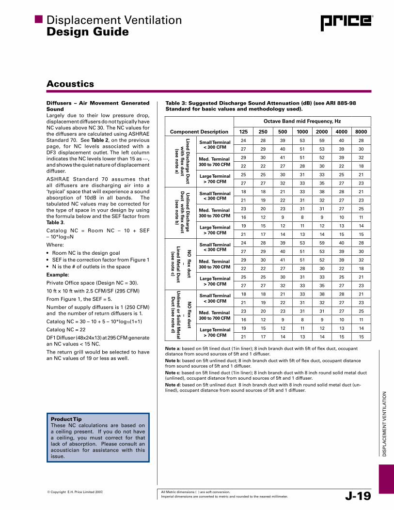
Table 3: Suggested Discharge Sound Attenuation (dB) (see ARI 885-98 Standard for basic values and methodology used).
Diffusers – Air Movement Generated SoundLargely due to their low pressure drop, displacement diffusers do not typically have NC values above NC 30. The NC values for the diffusers are calculated using ASHRAE Standard 70. See Table 2, on the previous page, for NC levels associated with a DF3 displacement outlet. The left column indicates the NC levels lower than 15 as ---, and shows the quiet nature of displacement diffuser.
ASHRAE Standard 70 assumes that all diffusers are discharging air into a ‘typical’ space that will experience a sound absorption of 10dB in all bands. The tabulated NC values may be corrected for the type of space in your design by using the formula below and the SEF factor from Table 3.
Catalog NC = Room NC – 10 + SEF – 10*log10N
Where:
• RoomNCisthedesigngoal• SEFisthecorrectionfactorfromFigure1 • Nisthe#ofoutletsinthespace
Example:
Private Office space (Design NC = 30).
10 ft x 10 ft with 2.5 CFM/SF (295 CFM)
From Figure 1, the SEF = 5.
Number of supply diffusers is 1 (250 CFM) and the number of return diffusers is 1.
Catalog NC = 30 – 10 + 5 – 10*log10(1+1)
Catalog NC = 22
DF1 Diffuser (48x24x13) at 295 CFM generate an NC values < 15 NC.
The return grill would be selected to have an NC values of 19 or less as well.
Product TipThese NC calculations are based on a ceiling present. If you do not have a ceiling, you must correct for that lack of absorption. Please consult an acoustician for assistance with this issue.
Component Description
Octave Band mid Frequency, Hz
125 250 500 1000 2000 4000 8000
Small Terminal< 300 CFM
24 28 39 53 59 40 28
27 29 40 51 53 39 30
Med. Terminal300 to 700 CFM
29 30 41 51 52 39 32
22 22 27 28 30 22 18
Large Terminal> 700 CFM
25 25 30 31 33 25 21
27 27 32 33 35 27 23
Small Terminal< 300 CFM
18 18 21 33 38 28 21
21 19 22 31 32 27 23
Med. Terminal300 to 700 CFM
23 20 23 31 31 27 25
16 12 9 8 9 10 11
Large Terminal> 700 CFM
19 15 12 11 12 13 14
21 17 14 13 14 15 15
Small Terminal< 300 CFM
24 28 39 53 59 40 28
27 29 40 51 53 39 30
Med. Terminal300 to 700 CFM
29 30 41 51 52 39 32
22 22 27 28 30 22 18
Large Terminal> 700 CFM
25 25 30 31 33 25 21
27 27 32 33 35 27 23
Small Terminal< 300 CFM
18 18 21 33 38 28 21
21 19 22 31 32 27 23
Med. Terminal300 to 700 CFM
23 20 23 31 31 27 25
16 12 9 8 9 10 11
Large Terminal> 700 CFM
19 15 12 11 12 13 14
21 17 14 13 14 15 15
Lined
Disch
arge Du
ct w
ith fl
ex du
ct(see n
ote a)
Un
lined
Disch
arge D
uct w
ith fl
ex du
ct(see n
ote b
)
NO
flex d
uct
– Lin
ed M
etal Du
ct(see n
ote c)
NO
flex d
uct
–U
nlin
ed o
r So
lid M
etal D
uct (see n
ote d
)
Note a: based on 5ft lined duct (1in liner); 8 inch branch duct with 5ft of flex duct, occupant distance from sound sources of 5ft and 1 diffuser.Note b: based on 5ft unlined duct; 8 inch branch duct with 5ft of flex duct, occupant distance from sound sources of 5ft and 1 diffuser.Note c: based on 5ft lined duct (1in liner); 8 inch branch duct with 8 inch round solid metal duct (unlined), occupant distance from sound sources of 5ft and 1 diffuser.Note d: based on 5ft unlined duct 8 inch branch duct with 8 inch round solid metal duct (un-lined), occupant distance from sound sources of 5ft and 1 diffuser.
Table 2: Sample Performance Data for a DF3
Unit Size[Face
Area, ft²]W x H x D
Inlet Size in.
Face Velocity
FPMAirflow
CFM
Total Pressure
in.wg.
Static Pres-sure
in.wg.
Noise Criteria
NC
24 x 24 x 13 [7.7]
10 20 155 - - -10 30 232 0.02 0.01 -10 40 310 0.04 0.02 -10 50 387 0.06 0.03 7

J-20 All Metric dimensions ( ) are soft conversion. © Copyright E.H. Price Limited 2007. Imperial dimensions are converted to metric and rounded to the nearest millimeter.
DIS
PLA
CE
ME
NT
vE
NT
ILA
TIO
N
Designing with AHUs and RTUs
Designing with Air Handling Units
When designing with Air Handling Units (AHUs), Figure 31, there are several options to consider, of which, some will be from off-the-shelf AHUs, while others will require a custom package.
AHUs in a displacement ventilation systems must be able to supply an off-coil supply air temperature of ~65°F [18°C] in order to limit discomfort.
When climate permits, the use of an economizer is recommended. This can increase the energy efficiency of the building while still creating the appropriate thermally comfortable indoor environment.
Where dehumidification is required, side steam by-pass or heat recovery wheels can be used to bring the air back to the correct supply air temperature, see the humidity control section for further information.
variable speed drives on a vAv system, Figure 32, will help to save energy under partial load conditions and will help to promote stratification in the space. If temperature reset systems are incorporated into the system the set point can be raised during low load conditions to extend the economizer cycle.
Demand control ventilation can be incorporated into the displacement system to help reduce the energy demand of the system in low load cases and still provide the proper space ventilation. An example of this would be a building management system (BMS) in conjunction with CO2 sensors for demand control ventilation schemes of partial use spaces.
For larger buildings, air handlers should feed each floor, or a range of floors, depending on the size or design of the building.
Designing with Packaged Rooftop Units (RTUs)
Generally, it is difficult to use packaged rooftops with a displacement ventilation system due to their intended use of delivering 55°F supply air. This will almost certainly cause discomfort in the zone and, therefore, should be used in combination with a heat recovery system.
A large DX system with multiple compressors and temperature reset capabilities can be used to produce the cooling requirements more efficiently, if the building can support a larger DX system.
Figure 31: Air Handling Unit (AHU)
Displacement ventilationDesign Guide
Figure 32: Variable Frequency Drives [source: Siemens Building Technologies Ltd.]
© Copyright E.H. Price Limited 2007. All Metric dimensions ( ) are soft conversion. Imperial dimensions are converted to metric and rounded to the nearest millimeter. J-21
DIS
PLA
CE
ME
NT
vE
NT
ILA
TIO
N
6 ft
1ft
1ft
Displacement ventilationDesign Guide
Loading Within the Space
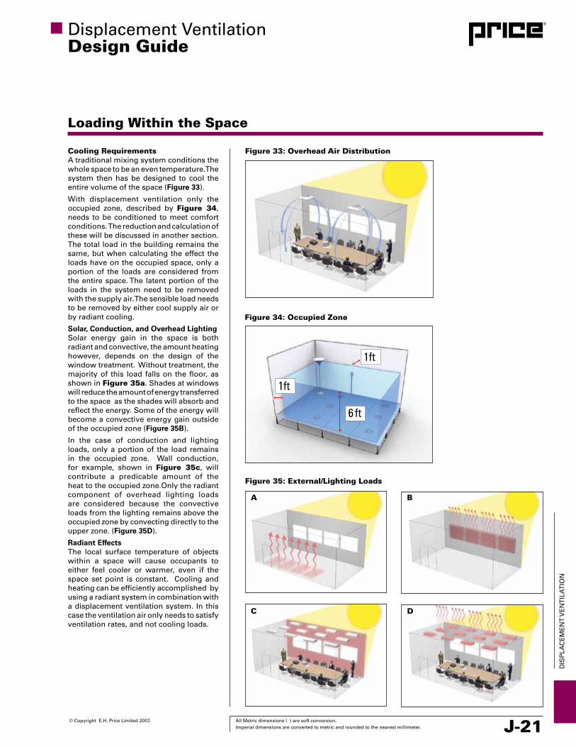
Cooling RequirementsA traditional mixing system conditions the whole space to be an even temperature. The system then has be designed to cool the entire volume of the space (Figure 33).
With displacement ventilation only the occupied zone, described by Figure 34, needs to be conditioned to meet comfort conditions. The reduction and calculation of these will be discussed in another section. The total load in the building remains the same, but when calculating the effect the loads have on the occupied space, only a portion of the loads are considered from the entire space. The latent portion of the loads in the system need to be removed with the supply air. The sensible load needs to be removed by either cool supply air or by radiant cooling.
Solar, Conduction, and Overhead LightingSolar energy gain in the space is both radiant and convective, the amount heating however, depends on the design of the window treatment. Without treatment, the majority of this load falls on the floor, as shown in Figure 35a. Shades at windows will reduce the amount of energy transferred to the space as the shades will absorb and reflect the energy. Some of the energy will become a convective energy gain outside of the occupied zone (Figure 35B).
In the case of conduction and lighting loads, only a portion of the load remains in the occupied zone. Wall conduction, for example, shown in Figure 35c, will contribute a predicable amount of the heat to the occupied zone.Only the radiant component of overhead lighting loads are considered because the convective loads from the lighting remains above the occupied zone by convecting directly to the upper zone. (Figure 35D).
Radiant EffectsThe local surface temperature of objects within a space will cause occupants to either feel cooler or warmer, even if the space set point is constant. Cooling and heating can be efficiently accomplished by using a radiant system in combination with a displacement ventilation system. In this case the ventilation air only needs to satisfy ventilation rates, and not cooling loads.
Figure 35: External/Lighting Loads
A
C
B
D
Figure 33: Overhead Air Distribution
Figure 34: Occupied Zone
J-22 All Metric dimensions ( ) are soft conversion. © Copyright E.H. Price Limited 2007. Imperial dimensions are converted to metric and rounded to the nearest millimeter.
DIS
PLA
CE
ME
NT
vE
NT
ILA
TIO
N
Figure 36: Radiant and Convective Portions of Heat Sources
Loading Within the Space
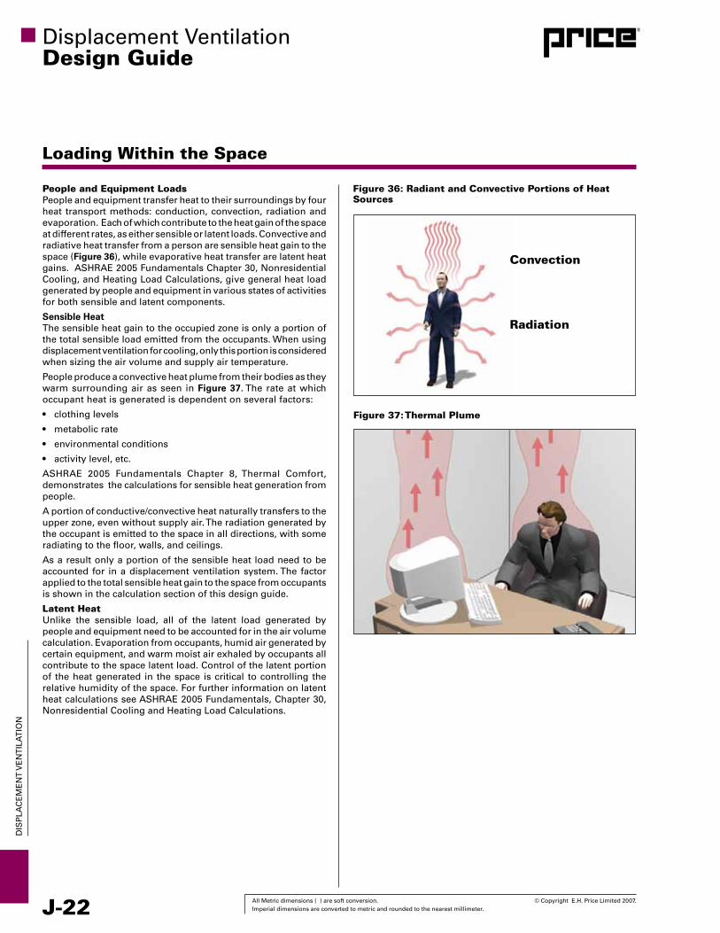
People and Equipment LoadsPeople and equipment transfer heat to their surroundings by four heat transport methods: conduction, convection, radiation and evaporation. Each of which contribute to the heat gain of the space at different rates, as either sensible or latent loads. Convective and radiative heat transfer from a person are sensible heat gain to the space (Figure 36), while evaporative heat transfer are latent heat gains. ASHRAE 2005 Fundamentals Chapter 30, Nonresidential Cooling, and Heating Load Calculations, give general heat load generated by people and equipment in various states of activities for both sensible and latent components.
Sensible Heat The sensible heat gain to the occupied zone is only a portion of the total sensible load emitted from the occupants. When using displacement ventilation for cooling, only this portion is considered when sizing the air volume and supply air temperature.
People produce a convective heat plume from their bodies as they warm surrounding air as seen in Figure 37. The rate at which occupant heat is generated is dependent on several factors:
• clothinglevels
• metabolicrate
• environmentalconditions
• activitylevel,etc.
ASHRAE 2005 Fundamentals Chapter 8, Thermal Comfort, demonstrates the calculations for sensible heat generation from people.
A portion of conductive/convective heat naturally transfers to the upper zone, even without supply air. The radiation generated by the occupant is emitted to the space in all directions, with some radiating to the floor, walls, and ceilings.
As a result only a portion of the sensible heat load need to be accounted for in a displacement ventilation system. The factor applied to the total sensible heat gain to the space from occupants is shown in the calculation section of this design guide.
Latent Heat Unlike the sensible load, all of the latent load generated by people and equipment need to be accounted for in the air volume calculation. Evaporation from occupants, humid air generated by certain equipment, and warm moist air exhaled by occupants all contribute to the space latent load. Control of the latent portion of the heat generated in the space is critical to controlling the relative humidity of the space. For further information on latent heat calculations see ASHRAE 2005 Fundamentals, Chapter 30, Nonresidential Cooling and Heating Load Calculations.
Displacement ventilationDesign Guide
Figure 37: Thermal Plume
Convection
Radiation

© Copyright E.H. Price Limited 2007. All Metric dimensions ( ) are soft conversion. Imperial dimensions are converted to metric and rounded to the nearest millimeter. J-23
DIS
PLA
CE
ME
NT
vE
NT
ILA
TIO
N
Displacement ventilationDesign Guide
Diffuser Type
Figure 38: One-Way DiffuserA wide variety of displacement air diffuser types are available to suit the location restrictions and décor of a particular room or space. In some cases the diffusers are custom fabricated to meet an area’s unique architectural design.
Some common displacement diffuser types are described as follows:
1. Rectangular UnitsRectangular units are typically placed against a wall or partition. If only the face of the unit is active, a one-way pattern is produced as seen in Figure 38. If both the face and sides are active, a three-way pattern results (Figure 39). The three-way diffuser has a higher air volume capacity than the one-way. Diffuser inlets are usually at the top of the unit, although bottom or rear inlets are available.
One version of the rectangular units is designed to be integrated into the wall (Figure 40). A narrow plenum and rectangular inlet are characteristic of this design.
Another version of a rectangular unit has no plenum or inlet and is designed for plenum feed applications. These units can be mounted in a stair riser, wall, cabinet, etc. and are supplied with a field fabricated plenum shown in Figure 41.
2. Corner UnitsCorner units are specifically designed to fit into a 90° corner in a room. Supply inlets can be located at the top or bottom of the unit. Flat or circular faces are available depending on the desired look. A 90° radial pattern is produced by corner units (Figure 42). These diffusers are ideal for applications where wall space may be limited as corners are available for use.
3. Displacement Linear EnclosureLinear enclosure can act as both a supply diffuser and as a heating source. These enclosure are suited for perimeter locations. As a heating source they are designed so that the heating element does not interfere with the air temperature or air flow patterns (Figure 43).
Figure 39: Three-Way Diffuser
Figure 40: Wall Mounted Figure 41: Recessed Diffuser
Figure 42: Corner DiffuserFigure 43: Displacement Linear Enclosure

J-24 All Metric dimensions ( ) are soft conversion. © Copyright E.H. Price Limited 2007. Imperial dimensions are converted to metric and rounded to the nearest millimeter.
DIS
PLA
CE
ME
NT
vE
NT
ILA
TIO
N
Displacement ventilationDesign Guide
Diffuser Type
4. Semi-circular UnitsShown in Figure 44 Semi-circular units are typically placed against a wall or pillar. Supply inlets can be located at the top, bottom or rear of the unit. A 180° radial pattern is produced.
5. Circular UnitsCircular units can supply high volumes of air to a space because the air is distributed in a complete 360° radial pattern (Figure 45).The supply inlet can be located at the top or bottom of the units. Circular units are typically placed free-standing in large interior spaces such as halls, lobbies, walkways, lounges, etc.
6. Floor Mounted UnitsDisplacement diffusers are available for integration with a raised floor distribution system. The round floor displacement unit produces a low velocity radial pattern across the floor as seen in Figure 46.
The floor mounted grilles can provide a linear pattern from the grille face. Displacement floor grilles can also be fan assisted (Figure 47) when additional air volumes are required and a fan terminal is not economical.
7. Industrial DiffusersFor the industrial environment diffusers need to be able to withstand impact from moving equipment, or able to be mounted above the working space and designed to supply air deep into the space (Figure 48). The Price industrial flat diffuser is intended to be placed on the industrial floor space and provide supply air. The robust design allows this diffuser to withstand the impact forces common to the industrial sector. The Krantz line of industrial diffusers are designed to be mounted above the occupied zone, and have integrated heating and cooling supply air modes.
Figure 44: Semi Circular Diffuser Figure 45: Circular Diffuser
Figure 46: Round Floor Grille Figure 47: Linear Floor Grille
Figure 48: Industrial Diffuser

© Copyright E.H. Price Limited 2007. All Metric dimensions ( ) are soft conversion. Imperial dimensions are converted to metric and rounded to the nearest millimeter. J-25
DIS
PLA
CE
ME
NT
vE
NT
ILA
TIO
N
Displacement ventilationDesign Guide
Diffuser Layout and Location
Figure 49: Wide RoomsDue to the variety of diffuser types available, displacement outlets can be mounted in numerous locations and configurations.
The following are some general recommendations for supply diffusers.
•Rectangularor semi-circularunitsareoften locatedonwallsopposite to the exterior windows and walls.
•For large rooms wider than 30 feet, consider mounting thediffuser on two opposite walls as seen in Figure 49 .
•Forroomslongerthan15feet,considerseveraldiffusersalongthe wall per Figure 50A.
•For largeopenspaces,roundorrectangulardiffuserscanbeplaced in the mid of the space (Figure 50B).
•Placediffusersnocloserthan2feetfromoccupantsasshownin Figure 51.
•Avoidplacinglargeobstaclesnearthediffuserface.
•Place more diffusers in areas which have a higher coolingload.
When ducting from below a diffuser it is important to supply the diffuser with a base for easy connection to the diffuser.
When mounting displacement diffuser; in the ceiling or at an elevated location, it is important to locate these above aisle ways or along perimeters. Placing a diffuser directly over an occupant will lead to occupant discomfort. Locating the diffusers along perimeters will help to reduce the heat gain and entrainment of pollutants as the air passes down through the stratified layers.
When mounting displacement diffusers along the walls it is important to provide support, due to the weight of the outlets.
In installations where the ductwork is supplied from above the diffuser and needs to be hidden, ensure that the cover will properly conceal the ductwork. Perforated covers may require the ductwork to be painted to conceal it completely.
When supplying displacement air to a room with a sloped floor, or ramp, place more of the diffusers at the upper level of the space. The cool air will want to flow down to the lower.
Regarding return air outlets, it is essential that they be placed at high levels either on the wall or in the ceiling. The same model types for mixing systems would apply to displacement systems. Locating the return air outlets above strong heat sources such as windows will ensure the efficient removal of the heat and contaminants generated by the thermal plume.
30 ft
Figure 50A: Long Rooms
15 ft
Figure 50B: Large Open Rooms
Figure 51: Distance from Diffusers
Product TipTo conceal ductwork from the ceiling to a floor mounted diffuser, a duct cover may be used. These covers are designed to match the look of the diffuser for a consistent architectural finish.

J-26 All Metric dimensions ( ) are soft conversion. © Copyright E.H. Price Limited 2007. Imperial dimensions are converted to metric and rounded to the nearest millimeter.
DIS
PLA
CE
ME
NT
vE
NT
ILA
TIO
N
Displacement ventilationDesign Guide
DV Supply AIr Methods
Figure 52: Ducted ConnectionDucted Connection
The most common method to supply air to a displacement diffuser is via a ducted connection. Diffusers can be connected from the top, bottom, and sides depending on the function and design of the diffuser.
Balancing dampers required for diffusers should be mounted at least 3 duct diameters away from the inlet connection on the diffuser, in a ducted configuration.
Pressurized Plenum:
When utilizing a pressurized plenum with a displacement diffuser, ensure that the plenum is properly sealed . Advantages of using a pressurized plenum are reduced ductwork easier balancing and quicker installation. For further information on pressurized plenum designs see the UFAD design guide.
Component Selection
Displacement diffusers designed for the commercial sector have a recommended maximum face velocity of 40 feet per minute to ensure comfort in the space. In transitional spaces such as lobbies, 50 feet per minute face velocities are acceptable.
The air volume, return air temperature, and supply air temperature are calculated values based on the room dynamics, see the Calculation section for full equations.
The type of diffuser is typically selected to match architecture or other space constraints. See the Diffuser Type section for summary descriptions of the diffusers offered by Price.
Installation
Generally floor mounted diffusers are provided with wall mounting strips, the DR360 is provided with a floor mounting ring. (Figure 54)
The DF1W installs into a engineered ducted plenum, provided with the diffuser.
The DF1R displacement diffuser is designed to fit into a pressurized plenum. Mounting flanges are provided for a tamper proof installation as shown in Figure 55.
Product TipWhen selecting a bottom duct diffuser ensure that the diffuser has a base if the product is floor mounted. This will make the diffuser easier to install in the field.
Product TipWhen selecting a bottom duct diffuser and a balancing damper is required, special designs may be required to accommodate the balancing of the diffuser. Allow for a base where possible.
Product TipThe DF1R, the DLE/DLE-H and the ARFHD all require pressurized plenums, they do not come standard with ducted connections.
Figure 53: Pressurized Plenum
Component Selection and Installation
Distance XFrom Floor to ScrewLocation
Mounting Plate
X
H
Figure 54: Typical Wall Mounting
Figure 55: DF1R Installation

© Copyright E.H. Price Limited 2007. All Metric dimensions ( ) are soft conversion. Imperial dimensions are converted to metric and rounded to the nearest millimeter. J-27
DIS
PLA
CE
ME
NT
vE
NT
ILA
TIO
N
Actual zone air flow rate is the maximum of the cooling air flow and the ventilation rate.
The supply air temperature is calculated from:
Where the temperature difference between head and foot is given by:
and:
Using αr and αcf = 0.95 BTU/h*ft²*°F from ASHRAE fundamentals.
The exhaust air temperature can be calculated from:
Where:
• ρ is the air density (lb/ft³),
• Cpisthespecificheatoftheairatconstantpressure(BTU/lb•°F),
• Histheheightoftheceiling(ft),
• Aistheareaofthespace(ft²),
• ΔThf is the temperature difference from heat to foot level (°F),
• η is the ventilation effectiveness of the space,
• Vf is the required fresh air rate for displacement ventilation (CFM),
• Vr is the flow required for acceptable indoor air quality (CFM),
• Ts is the supply air temperature (°F),
• Θf is a dimensionless temperature,
• Te is the exhaust air temperature (°F)
Figure 56: Cooling Loads
Overhead Lighting
Conduction and Solar
Occupant and Equipement
Displacement ventilationDesign Guide
Displacement Ventilation Air Volume Calculations
Cooling Flow RateDue to the higher supply air temperatures inherent with displacement ventilation, it is often assumed that the cooling supply air flow rate will be significantly greater when compared to a traditional overhead mixing system. However, since a proportion of the heat sources in a room are exhausted directly without impacting the occupied space, displacement ventilation flow rates can be equal or even lower than mixing systems, depending on room layout and space type (Figure 56).
Due to stratification, each heat source will have a different effect upon the loads in the space. Since some heat sources are above the occupied zone, we can include a load factor for their contribution to the total space load. Typical Heat sources have both radiant and convective components so it is important to assign loads to the occupied zone and the upper zone, depending on the load type.
In determining the air volume requirements for an all air displacement ventilation system the ASHRAE Design Guide has developed a procedure to calculate the cooling supply flow rate, taking into account the stratified loads.
Loads can be divided into the following three catagories:
• Theoccupants,desklampsandequipment,Qoe (Btu/h).
• Theoverheadlighting,Ql (Btu/h).
• Theheatconductionthroughtheroomenvelopeandtransmittedsolar radiation, Qex (Btu/h).
Such that, the total cooling load is:
Qt = Qoe + Ql + Qex
Load factors for the above catagories have been determined by ASHRAE research project RP-949.
• Occupants,desklampsandequipment,aoe = 0.295 Approximately 1/3 of this cooling load enters the space between foot and head level. The other 2/3 enters the upper space via the thermal plume and radiation.
• Overheadlighting,al = 0.132 Less than 15% of the total lighting load is radiated to the occupied space.
• Heatconductionandsolarradiation,aex = 0.185 More than 80% of the external loads enter the upper space via the thermal plume and radiation.
Based on the coefficients above, the ASHRAE Design Guide lists the following equations for determining summer cooling flow rates for a typical office space.
Determination of the required air flow rate for summer cooling:
Determination of the ventilation rate:
vr is determined from ASHRAE Standard 62-2004 based on room application. Local codes may not allow the discount for the ventilation effectiveness, or may have stricter requirements. Refer to ASHRAE Standard 62.1 for recognized values of ventilation effectiveness.
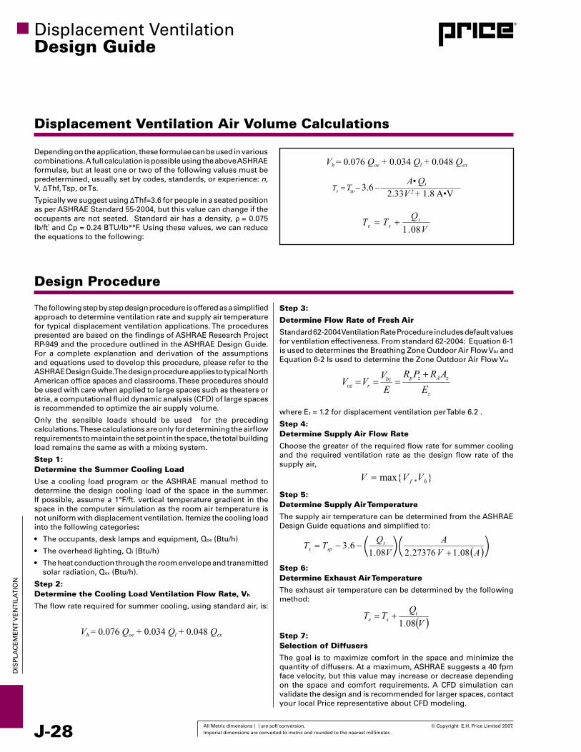
J-28 All Metric dimensions ( ) are soft conversion. © Copyright E.H. Price Limited 2007. Imperial dimensions are converted to metric and rounded to the nearest millimeter.
DIS
PLA
CE
ME
NT
vE
NT
ILA
TIO
N
Step 3:
Determine Flow Rate of Fresh Air
Standard 62-2004 ventilation Rate Procedure includes default values for ventilation effectiveness. From standard 62-2004: Equation 6-1 is used to determines the Breathing Zone Outdoor Air Flow vbz and Equation 6-2 Is used to determine the Zone Outdoor Air Flow voz
where Ez = 1.2 for displacement ventilation per Table 6.2 .
Step 4:Determine Supply Air Flow Rate
Choose the greater of the required flow rate for summer cooling and the required ventilation rate as the design flow rate of the supply air,
Step 5:Determine Supply Air Temperature
The supply air temperature can be determined from the ASHRAE Design Guide equations and simplified to:
Step 6:Determine Exhaust Air Temperature
The exhaust air temperature can be determined by the following method:
Step 7: Selection of Diffusers
The goal is to maximize comfort in the space and minimize the quantity of diffusers. At a maximum, ASHRAE suggests a 40 fpm face velocity, but this value may increase or decrease depending on the space and comfort requirements. A CFD simulation can validate the design and is recommended for larger spaces, contact your local Price representative about CFD modeling.
Displacement ventilationDesign Guide
Displacement Ventilation Air Volume Calculations
Depending on the application, these formulae can be used in various combinations. A full calculation is possible using the above ASHRAE formulae, but at least one or two of the following values must be predetermined, usually set by codes, standards, or experience: n, v, ΔThf, Tsp, or Ts.
Typically we suggest using ΔThf=3.6 for people in a seated position as per ASHRAE Standard 55-2004, but this value can change if the occupants are not seated. Standard air has a density, ρ = 0.075 lb/ft² and Cp = 0.24 BTU/lb*°F. Using these values, we can reduce the equations to the following:
Design Procedure
The following step by step design procedure is offered as a simplified approach to determine ventilation rate and supply air temperature for typical displacement ventilation applications. The procedures presented are based on the findings of ASHRAE Research Project RP-949 and the procedure outlined in the ASHRAE Design Guide. For a complete explanation and derivation of the assumptions and equations used to develop this procedure, please refer to the ASHRAE Design Guide. The design procedure applies to typical North American office spaces and classrooms. These procedures should be used with care when applied to large spaces such as theaters or atria, a computational fluid dynamic analysis (CFD) of large spaces is recommended to optimize the air supply volume.
Only the sensible loads should be used for the preceding calculations. These calculations are only for determining the airflow requirements to maintain the set point in the space, the total building load remains the same as with a mixing system.
Step 1:Determine the Summer Cooling Load
Use a cooling load program or the ASHRAE manual method to determine the design cooling load of the space in the summer. If possible, assume a 1°F/ft. vertical temperature gradient in the space in the computer simulation as the room air temperature is not uniform with displacement ventilation. Itemize the cooling load into the following categories:
• Theoccupants,desklampsandequipment,Qoe (Btu/h)
• Theoverheadlighting,Ql (Btu/h)
• Theheatconductionthroughtheroomenvelopeandtransmitted solar radiation, Qex (Btu/h).
Step 2:Determine the Cooling Load Ventilation Flow Rate, Vh
The flow rate required for summer cooling, using standard air, is:
Vh = 0.076 Qoe + 0.034 Ql + 0.048 Qex
Vh = 0.076 Qoe + 0.034 Ql + 0.048 Qex
3.6A• Qt
2.33V 2 + 1.8 A•V

© Copyright E.H. Price Limited 2007. All Metric dimensions ( ) are soft conversion. Imperial dimensions are converted to metric and rounded to the nearest millimeter. J-29
DIS
PLA
CE
ME
NT
vE
NT
ILA
TIO
N
Displacement ventilationDesign Guide
Small Office Example
Space Design
The owner of an office building is renovating and would like to consider using displacement ventilation in the office areas. This example examines a small office in this space. The office is a north facing room, used primarily during the hours from 8:00 to 12:00, and from 13:00 to 17:00. The space is designed for 2 occupants, a computer with LCD monitor, T8 florescent lighting, and has a control temperature of 72°F. The room is 10 ft wide, 12 ft long, and 9 ft from floor to ceiling. The owner expressed interest in supplying the office spaces with wall mounted displacement diffusers or corner displacement diffuser as space is limited.
Space Considerations
One of the primary considerations when using a Dv system is comfort. As previously discussed, ASHRAE standard 55-2004 stipulates the maximum combination of velocity and temperature in the occupied zone, PPD due to draft, as well as the stratification in the space. In an office, the occupants tend to be in a seated position; the stratification for a sedentary seated person according to ASHRAE 55 is 3.6F.
The assumptions made for the space are as follows:
• Loadperpersonis250BTU/h
• Lightingloadinthespaceis6.82BTU/h/ft²
• Computerloadis308BTU/h(CPUandLCDMonitor)
• Conductionthroughthewindowandwallis5BTU/h/ft²
• Thespecificheatanddensityoftheairorthisexamplewillbe0.24BTU/lb°Fand0.075lb/ft³respectively.
Occupants 2
Set Point 72 °F
Floor Area 120 ft²
Exterior Wall Area 90 ft²
volume 1080 ft³
Qoe 1012 BTU/h
Ql 819 BTU/h
Qex 450 BTU/h
QT 2281 BTU/h
The loads are broken down as follows:
Qoe = (2 People X 250 BTU/h) + 308 BTU/h = 808 BTU/h
Ql = 120 ft² X 6.82 BTU/h/ft² = 819 BTU/h
Qex = 90 ft² X 5 BTU/h/ft² = 450 BTU/h
QT = 2077 BTU/h
Total cooling load for this space (QT) is 2077 BTU/h, and approximately 17.31 BTU/h/ft².
ASHRAE Standard 62-2004 requires 0.06 CFM/ft² outdoor airflow rate required per unit area, Ra, and 5 CFM/Person outdoor airflow rate required per person, Rp, be delivered to the space for moderately active office work applications. For displacement ventilation a ventilation effectiveness, or zone air distribution effectiveness (Ez), assumed to be 1.2 (table 6-2, ASHRAE Standard 62-2004).

J-30 All Metric dimensions ( ) are soft conversion. © Copyright E.H. Price Limited 2007. Imperial dimensions are converted to metric and rounded to the nearest millimeter.
DIS
PLA
CE
ME
NT
vE
NT
ILA
TIO
N
Displacement ventilationDesign Guide
Small Office Example
Determine the Airflow Rate to meet the Cooling Load
Determine the Fresh Air Flow Rate and Breathing Zone Ventilation Effectiveness
Note: Some local codes may not allow the discount for vE, or may have stricter requirements, and they should be used instead of this calculation. Example: Title 24 in California.
The total supply air volume for cooling is then the maximum value between vh and vr.
Calculate the Supply Air Temperature
Determine the Return Air Temperature
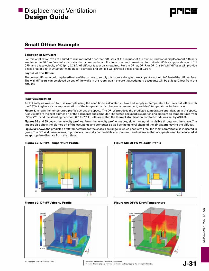
© Copyright E.H. Price Limited 2007. All Metric dimensions ( ) are soft conversion. Imperial dimensions are converted to metric and rounded to the nearest millimeter. J-31
DIS
PLA
CE
ME
NT
vE
NT
ILA
TIO
N
Displacement ventilationDesign Guide
Small Office Example
Selection of Diffusers
For this application we are limited to wall mounted or corner diffusers at the request of the owner. Traditional displacement diffusers are limited to 40 fpm face velocity in standard commercial applications in order to meet comfort criteria. With a supply air rate of 111 CFM and a face velocity of 40 fpm, 2.78 ft² of diffuser face area is required. For the DF1W, DF1R or DF1C a 24”x18”diffuser will provide a face area of 3 ft². A DR90 unit with an 18” diameter and 30” tall will provide a face area of 2.94 ft².
Layout of the Office
The corner diffusers could be placed in any of the corners to supply this room, as long as the occupant is not within 2 feet of the diffuser face. The wall diffusers can be placed on any of the walls in the room, again ensure that sedentary occupants will be at least 2 feet from the diffuser.
Flow Visualization
A CFD analysis was run for this example using the conditions, calculated airflow and supply air temperature for the small office with the DF1W to give a visual representation of the temperature distribution, air movement, and draft temperatures in the space.
Figure 57 shows the temperature profiles across the space. The DF1W produces the predicted temperature stratification in the space. Also visible are the heat plumes off of the occupants and computer. The seated occupant is experiencing ambient air temperatures from 69º to 72º F, and the standing occupant 69º to 75º F. Both are within the thermal stratification comfort conditions set by ASHRAE.
Figures 58 and 59 depict the velocity profiles. From the velocity profile images, slow moving air is visible throughout the space. The images also show the plumes off of the occupants and computer as well as the general shape of the air pattern leaving the diffuser.
Figure 60 shows the predicted draft temperature for the space. The range in which people will feel the most comfortable, is indicated in green. The DF1W diffuser seems to produce a thermally comfortable environment, and reiterates that occupants need to be located at an appropriate distance from the diffuser.
Figure 57: DF1W Temperature Profile Figure 58: DF1W Velocity Profile
Figure 59: DF1W Velocity Profile Figure 60: DF1W Draft Temperature

J-32 All Metric dimensions ( ) are soft conversion. © Copyright E.H. Price Limited 2007. Imperial dimensions are converted to metric and rounded to the nearest millimeter.
DIS
PLA
CE
ME
NT
vE
NT
ILA
TIO
N
Displacement ventilationDesign Guide
Boardroom Example
Space Design
The owner of a new office building wants to use a displacement ventilation system for all occupied spaces. This example examines a private boardroom that is located in the center of the building without any exterior surfaces. The space is designed for 8 occupants, a computer with LCD monitor, a projector, T8 florescent lighting, and has a control temperature of 72°F. The room is 24 ft wide, 14 ft long, and 10 ft from floor to ceiling. There is a large white board at the west end of the room and cabinets along the south and east end of the room. The owner and architect want the displacement diffusers in the space to fit seamlessly into the room.
Space Considerations
• TheheadtofootgradientrecommendedbyASHRAEis3.6°Ffromheadtofootforseatedoccupants.
• Someoftheassumptionsmadeforthespaceareasfollows:
• Loadperpersonis250BTU/h
• Lightingloadinthespaceis6.82BTU/h/ft²
• ComputerandLCDloadis308BTU/h
• Projectorloadis188BTU/h
• Thespecificheatanddensityoftheairorthisexamplewillbe0.24BTU/lb°Fand0.075lb/ft³respectively.
Occupants 8
Set Point 72 °F
Floor Area 336 ft²
volume 3360 ft³
Qoe 2496 BTU/h
Ql 2294 BTU/h
Qex 0 BTU/h
QT 4790 BTU/h
The loads are broken down as follows:
Qoe = (8 People X 250 BTU/h) + 308 BTU/h + 188 BTU/h = 2496 BTU/hQl = 336 ft² X 6.82 BTU/h/ft² = 2294 BTU/h
Qex = 0 BTU/h
QT = 4790 BTU/h
Total cooling load for this space (QT) is 4790 BTU/h, and approximately 14.26 BTU/h/ft².
ASHRAE Standard 62-2004 requires 0.06 CFM/ft² outdoor airflow rate required per unit area, Ra, and 5 CFM/Person outdoor airflow rate required per person, Rp, be delivered to the space for moderately active office work applications. For displacement ventilation a ventilation effectiveness, or zone air distribution effectiveness (Ez), is assumed to be 1.2 (table 6-2, ASHRAE standard 62-2004).

© Copyright E.H. Price Limited 2007. All Metric dimensions ( ) are soft conversion. Imperial dimensions are converted to metric and rounded to the nearest millimeter. J-33
DIS
PLA
CE
ME
NT
vE
NT
ILA
TIO
N
Displacement ventilationDesign Guide
Boardroom Example
Determine the Airflow Rate to meet the Cooling Load
Determine the Fresh Air Flow Rate and Breathing Zone Ventilation Effectiveness
Note: Some local codes may not allow the discount for vE, or may have stricter requirements, and they should be used instead of this calculation. Example: Title 24 in California.
The total supply air volume is then the maximum value between vh and vr.
Calculate the Supply Air Temperature
Determine the Return Air Temperature

J-34 All Metric dimensions ( ) are soft conversion. © Copyright E.H. Price Limited 2007. Imperial dimensions are converted to metric and rounded to the nearest millimeter.
DIS
PLA
CE
ME
NT
vE
NT
ILA
TIO
N
Displacement ventilationDesign Guide
Boardroom Example
Selection of Diffusers
For this application we have three goals set by the owner:
1. Quiet operation
2. Thermal comfort to the space
3. Diffusers must be hidden
Inherently, displacement ventilation diffusers are quiet, but care has to be taken to limit the sound generated from the HvAC air supply. Price recommends limiting the duct velocity to 1200 fpm, to minimize noise from ductwork. For thermal comfort a face velocity of 40 fpm is required. At 126 CFM a diffuser face area of 6.68 ft² would be required.
To make these diffusers as unobtrusive as possible there a two options; mount them in the wall, or as part of the furniture.
Layout of the Boardroom
For a concealed look, the DF1R displacement diffuser could be installed at the base of the cabinets, or in the wall under the whiteboard in a pressurized plenum. Two diffusers at 60”x8” will be able to meet the 40 fpm requirement. The diffusers can be placed on any of the walls in the room, but they must ensure that sedentary occupants will be located at least 2 feet from the diffuser.
Flow Visualization
A CFD analysis was run for this example using the conditions, calculated airflow and supply air temperature for the small office with the DF1W to give a visual representation of the temperature distribution, air movement, and draft temperatures in the space.
Figure 61 shows the temperature profiles across the space and a reasonable temperature stratification is predicted. Also visible are the heat plumes off of the occupants and computer. The seated occupant is experiencing ambient air temperatures from 69º to 72º F, and the standing occupant 69º to 75º F. Both are within the thermal stratification comfort conditions set by ASHRAE.
Figures 62 depict the velocity profile. The images show the plumes off of the occupants and computer as well as the general shape of the air pattern leaving the diffuser and slowly entering the zone.
Figure 63 depicts the draft temperature for the space. Again, the range in which people will feel the most comfortable is indicated in green. The DF1R diffusers produce a thermally comfortable space.
Figure 61: DF1R Temperature Profile Figure 62: DF1R Velocity Profile
Figure 63: DF1R Draft Profile

SPECIAL APPLICATION SUPPLEMENTALDISPLACEMENT VENTILATION SECTION J:
Machine Shops
Schools
Hospitals
w w w. p r i c e - h v a c . c o m

J-36 All Metric dimensions ( ) are soft conversion. © Copyright E.H. Price Limited 2007. Imperial dimensions are converted to metric and rounded to the nearest millimeter.
DIS
PLA
CE
ME
NT
vE
NT
ILA
TIO
N
Industrial Displacement Ventilation
Figure 64: Heavy Pollutant ConcentrationIndustrial ApplicationsDisplacement ventilation is ideally suited for the industrial sector. In fact, modern displacement ventilation was first used in factories of Europe. The increased ventilation effectiveness and inherent pollution control of displacement ventilation ensures a clean breathing zone for occupants.
Diffuser LocationIn most industrial applications, the floor plan is set up with a certain degree of flexibility. As the environment evolves, there is often the need to reconfigure the space. With this in mind, it is advantageous to mount displacement diffusers beside permanent fixtures such as roof supports and off of the floor in order to facilitate reconfiguration and to protect the diffusers from damage from forklifts, equipment, and materials moving throughout the facility.
Weight of PollutantsIn industrial environments with pollutants that are lighter than air, the same principles apply as in the commercial application of displacement ventilation, where the supply diffusers are typically supplying at a low level and returns are located high within the space.
For environments with pollutants that are heavier than air, such as carbon monoxide (CO), Ozone (03), some paint vOCs, there is the possibility that these pollutants can collect in the lower portion of a space (Figure 64). It is recommended that diffusers supply ventilation from above the occupant and exhaust is located at a low level. The low level exhaust will serve as an outlet for these gasses. When a low level return is used, diffuser placement is critical in an effort to reduce short circuiting. The displacement diffuser should be mounted above the occupied zone so that supply air has a chance to travel through the breathing zone and the occupied zone and carries with it some pollutants. Figure 65 shows a layout for an automotive garage. An automotive garage may have fumes from exhaust which linger due to their density. In this example, there are outlets at a high level as is typical of displacement ventilation but there is also an outlet near the floor level to exhaust any fumes being stored.
Diffuser SelectionUnlike commercial displacement ventilation diffusers, the industrial diffuser is selected based on adjacent zone. The object is to provide as much quality air to the occupants and ensure stratification , while still ensuring a comfortable space. Adjacent zones should not overlap, and should come as close to each other as possible, as the goal is to provide fresh air evenly throughout the space. The diffusers are not limited by the 40 fpm face velocity, and have a wide range, depending on the diffusers functionality.
Figure 65: Pollutant Extraction
Displacement ventilationDesign Guide—Special Supplemental

© Copyright E.H. Price Limited 2007. All Metric dimensions ( ) are soft conversion. Imperial dimensions are converted to metric and rounded to the nearest millimeter. J-37
DIS
PLA
CE
ME
NT
vE
NT
ILA
TIO
N
Machine Shop Example
Space Design
A machine shop owner has outgrown his existing operations and is renovating an older building. To provide good internal air quality and save on energy the owner wants to supply air in the shop with displacement ventilation. This example examines the shop floor in this space. The shop floor is designed for 35 occupants, 40 machines, Mercury vapor Light Fixtures, and has a control temperature of 75°F. The space is 88 ft wide, 90 ft long, 15 ft from floor to ceiling. The owner doesn’t want any of the diffusers to take up floor space, but will allow diffusers to be placed on columns, and wants the diffusers to operate in both heating and cooling modes.
Space Considerations
In this machine shop, pollutants generated in the space are lighter than air, so the exhausts need to be located high in the space and the diffusers in or near the occupied zone.
with the assumptions made for the space are as follows:
• Loadperpersonis375BTU/h
• Lightingloadinthespaceis10.234BTU/h/ft²
• Machineloadis:
• 6x5-axisCNC’sat9435BTU/heach
• 4xHorizontalturningmill’sat7609BTU/heach
• 5xVerticalmill’sat7636BTU/heach
• 5xLatheat6210BTU/heach
• 10xDrillat6439BTU/heach
• 10xSawat3388BTU/heach
• The“U”valuesforthewallis.045BTU/h/ft²•°F,andfortheroofis.031BTU/h/ft²•°F
• Thespecificheatanddensityoftheairorthisexamplewillbe0.24BTU/lb°Fand0.075lb/ft³ respectively.
Occupants 35
Set Point 75 °F
Floor Area 7920 ft²
Exterior Wall Area 2670 ft²
volume 118800 ft³
Qoe 314591 BTU/h
Ql 81053 BTU/h
Qex 6582 BTU/h
QT 402226 BTU/h
The loads are broken down as follows:
Qoe = (35 People X 375 BTU/h) + (33880 + 64390 + 31050 + 38180 + 30436 + 56610) BTU/h = 267671 BTU/h
Ql = 7920 ft² X 10.234 BTU/h/ft² = 81053 BTU/h
Qex=(2670ft²X.045BTU/h/ft²•°FX18°F)+(7920ft²X.031BTU/h/ft²•°FX18°F)=6582BTU/h
QT = 355306 BTU/h
Total cooling load for this space (QT) is 355306 BTU/h, and approximately 44.86 BTU/h/ft².
ASHRAE Standard 62-2004 requires 0.18 CFM/ft² outdoor airflow rate required per unit area, Ra, and 10 CFM/Person outdoor airflow rate required per person, Rp, be delivered to the space machine shop applications. For displacement ventilation a ventilation effectiveness, or zone air distribution effectiveness (Ez), assumed to be 1.2 (table 6-2, ASHRAE standard 62-2004).
Displacement ventilationDesign Guide—Special Supplemental
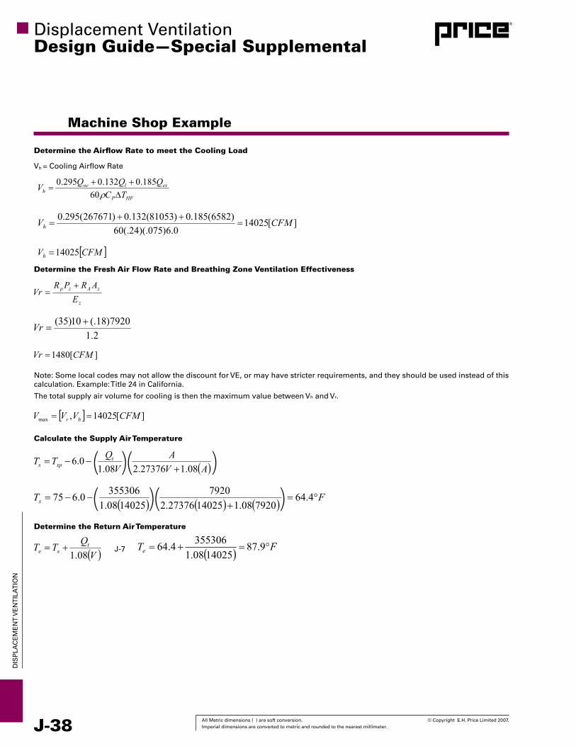
J-38 All Metric dimensions ( ) are soft conversion. © Copyright E.H. Price Limited 2007. Imperial dimensions are converted to metric and rounded to the nearest millimeter.
DIS
PLA
CE
ME
NT
vE
NT
ILA
TIO
N
Machine Shop Example
Determine the Airflow Rate to meet the Cooling Load
Determine the Fresh Air Flow Rate and Breathing Zone Ventilation Effectiveness
Note: Some local codes may not allow the discount for vE, or may have stricter requirements, and they should be used instead of this calculation. Example: Title 24 in California.
The total supply air volume for cooling is then the maximum value between vh and vr.
Calculate the Supply Air Temperature
Determine the Return Air Temperature
Displacement ventilationDesign Guide—Special Supplemental

© Copyright E.H. Price Limited 2007. All Metric dimensions ( ) are soft conversion. Imperial dimensions are converted to metric and rounded to the nearest millimeter. J-39
DIS
PLA
CE
ME
NT
vE
NT
ILA
TIO
N
Machine Shop Example
Selection of Diffusers
The DR360i-HC will be the best choice for this space, as it can perform the heating and cooling, it can be mounted above the occupied zone and along columns. Heat cool changeover may be accomplished by an actuator, controlled though the BMS or by Bowden cable. Unlike the commercial applications, the face velocity is not limited to the 40 fpm face velocity.
Placed 3 m above ground: Heating
Placed 3 m above ground: Cooling
In this example, diffusers are placed on the columns, to keep the floor area clear. The entire floor surface must be serviced by the diffusers, so an appropriate adjacent zone must be selected. To provide the proper floor coverage an adjacent zone of 20 feet is selected. The 14” diameter diffuser provides the 20 feet adjacent zone for the smallest pressure drop and noise level at 1165 CFM. For the 14025 CFM the space requires a total of 12 diffusers, each with a supply air volume rate of 1169 CFM.
For further instructions on heating mode operation see the industrial diffusers section of this design guide.
Layout of the Shop
The diffusers should be mounted on columns evenly throughout the space about 9 feet above floor level. For the diffusers with heat/cool changeover, the Bowden cable should be mounted in close proximity to the diffuser and needs to be accessible to the occupants. As with commercial applications, returns should be located as high as possible in the space.
Displacement ventilationDesign Guide—Special Supplemental
Unit Size Face Vel Airflow Total Pressure Static Pressure SPL ∆T = 18°F (Face Area) fpm cfm in WG in WG dBA ft.
10 75 488 0.214 0.164 48 Note 1 [6.5 ft2] 100 650 0.386 0.297 56 Note 1 125 813 0.608 0.470 62 Note 1 150 975 0.882 0.683 67 Note 1 14 75 870 0.156 0.115 45 Note 1 [11.6 ft2] 100 1160 0.281 0.208 52 Note 1 125 1450 0.445 0.330 59 Note 1 150 1740 0.645 0.480 64 Note 1 18 100 1470 0.214 0.171 53 Note 1 [14.7 ft2] 125 1838 0.329 0.262 58 Note 1 150 2205 0.467 0.370 62 Note 1 175 2573 0.628 0.496 66 Note 1 25 150 3090 0.249 0.198 56 Note 1 [20.6 ft2] 175 3605 0.339 0.269 60 Note 1 200 4120 0.441 0.350 64 Note 1 225 4635 0.557 0.442 67 Note 1
Adjacent Zone
(Cooling)
Unit Size Face Vel Airflow Total Pressure Static Pressure SPL ∆T = 5°F ∆T = 10°F (Face Area) fpm cfm in WG in WG dBA ft. ft.
14 50 580 0.068 0.050 36 16 <6 [11.6 ft2] 75 870 0.156 0.115 45 28 21 100 1160 0.281 0.208 52 32 26 125 1450 0.445 0.330 59 45 37 18 75 1103 0.123 0.099 47 27 19 [14.7 ft2] 100 1470 0.214 0.171 53 38 31 125 1838 0.329 0.262 58 45 36 150 2205 0.467 0.370 62 52 42 25 100 2060 0.112 0.089 47 32 24 [20.6 ft2] 125 2575 0.174 0.138 52 37 29 150 3090 0.249 0.198 56 42 36 175 3605 0.339 0.269 60 47 41
Adjacent Zone (Heating)
Performance Notes: 1. The maximum supply air penetration depth for floor mounted diffusers when cooling largely depends on the number and intensity of the heat sources. Under normal
circumstances a max supply air penetration of 32 ft with 10 inch unit and 82 ft with 25 inch unit.
Machine Shop Example

J-40 All Metric dimensions ( ) are soft conversion. © Copyright E.H. Price Limited 2007. Imperial dimensions are converted to metric and rounded to the nearest millimeter.
DIS
PLA
CE
ME
NT
vE
NT
ILA
TIO
N
Machine Shop Example
Figure 67: Temperature Profile
Flow VisualizationAirflow in the machine shop can be visualized through a CFD simulation or physical mock-up. A CFD simulation can ensure that the outlet locations, sizes and quantities are reasonably selected and help ensure that the space is optimized for energy performance and thermal comfort.
A CFD analysis was run for this example using the conditions and calculated airflow and supply air temperature. Figure 66 and 67 show the temperature profiles throughout the space. The space is stratified and the design set point of 74 was met. Figure 68 shows the temperature surface of 74 colored for velocity, to show how the air is delivered from the diffusers to the occupied zone. Figure 69 shows the velocity profile of the space, the space doesn’t show jets or major movements of air. Figure 70 shows the draft temperature. With the temperatures and velocities in the space, there are not any areas within the occupied zone where the draft temperature is excessive.
Figure 68: Diffuser Airflow Pattern
Figure 69: Velocity Profile Figure 70: Draft Temperature Profile
Figure 66: Temperature Profile
Displacement ventilationDesign Guide—Special Supplemental

© Copyright E.H. Price Limited 2007. All Metric dimensions ( ) are soft conversion. Imperial dimensions are converted to metric and rounded to the nearest millimeter. J-41
DIS
PLA
CE
ME
NT
vE
NT
ILA
TIO
N
% Im
prov
emen
t / R
educ
tion
in S
ympt
oms
BeijingResidence
Liu et al 1996
Australian Residence
Liu et al 1996
Wargocki1998
Jaakkdaet al 1994
Wies-lander et al 1997
100%
90%
80%
70%
60%
50%
40%
30%
20%
10%
85.0%Colds
61.5%Asthma, Allergies
47.0%SBS
23.6%Asthma
21.4% Asthma, Mucosal
Displacement ventilationDesign Guide—Special Supplemental
Displacement Ventilation and Schools
High Performance Schools
As operating costs for schools continue to increase, there is an increased demand to construct schools that are more resource efficient, sustainable, and have improved learning and health benefits. As this demand increased, several studies have been conducted and organizations formed to meet the need for information and establish baselines. Most notably the Collaborative for High Performing Schools (CHPS) was initiated in California, based on the USGBC LEED® Program, to meet the needs of school design. The CHPS program is a self-certification and recognition program designed to “facilitate the design of high performance schools: environments that are not only energy efficient, but also healthy, comfortable, well let; and containing the amenities needed for a quality education”.
Benefits from a Displacement Ventilation System
As described throughout this design guide, there are several benefits to applying a displacement type system to commercial spaces. The major benefits are:
• Longer “Free Cooling” periods due of higher supply airtemperatures
• LowerSystemPressureRequirements
• Higherindoorairquality
• Improvedthermalcomfort
• Lownoisegenerationfromdiffusers
These benefits correlate to the cost of running a building as well as the health and well being of the occupants.
In certain markets, the longer free cooling periods allow for an economizer to run longer during the day, leading to a lower operating equipment cost of the building. As well, the lower system pressure can allow for a reduction in the size of the fan or motor driving the fan to that zone, which will lead to lower energy consumption for the building during operation.
In a displacement ventilation system, the natural thermal plumes of each occupant drive the movement of air, and each person is delivered the amount of cooling that they require.Because this air has not been mixed with room air the air moving up the occupant is cool and unpolluted. This results in a stratified environment, with fresh, cool air at the lower portions and warm, polluted air a high level in the space. This leads to the high indoor air quality, as the occupants thermal plumes dictate the required amount of air delivered to the occupant. These benefits have been translated into cost savings, in a 2006 report by Gregory Kats at Capital E, the thermal comfort and air quality of schools were presented as a dollar and performance value. Furthermore, this report collected the findings of various researchers demonstrating the reduction in transmission of airborne illnesses. Figures 72 and 73 show these reductions by increasing the ventilation rate and applying pollutant source controls, respectively.
Green Tip Using displacement ventilation for schools is a great way to increase the ventilation effectiveness in a classroom. CHPS credit EQ2.1: Thermal Displacement ventilation gives two credit points for the use of displacement ventilation in the building.
Figure 71: Airflow Pattern with Displacement Ventilation
Applicable Spaces Climates When to Consider DVClassrooms South Coast ProgrammingLibrary North Coast SchematicMulti-Purpose/Cafeteria
Central valley
Design Development
Gym Mountains Contract Docs. Corridors Desert ConstructionAdministration CommissioningToilets OperationOther
Figure 73: Pollutant Source Controls
% Im
prov
emen
t / R
educ
tion
in S
ympt
oms
Drinkaet al1996
Jaakkda&
Miettinen1995
Brundageet al1985
Bourbeauet al 1997
Sundell1996
Fisk & Rosenfeld
1995
Fisk & Rosendfeld
1995
100%
90%
80%
70%
60%
50%
40%
30%
20%
10%
87.3%Flu
67.0%SBS
46.0%Resipatory
33.6% SBS
33.0% SBS
35.0%SBS
20.0%Resipatory
Figure 72: Increased Outdoor Air
Table 4: Applicability of Displacement Ventilation

J-42 All Metric dimensions ( ) are soft conversion. © Copyright E.H. Price Limited 2007. Imperial dimensions are converted to metric and rounded to the nearest millimeter.
DIS
PLA
CE
ME
NT
vE
NT
ILA
TIO
N
Figure 74: DFXi
Displacement ventilationDesign Guide—Special Supplemental
Displacement Ventilation and Schools
Table 5: Financial Benefits from Green Schools [Source: Capital E]
With the increase of indoor air quality, there is a positive impact on health, most notably a reduction in asthma complications, flu, sick building syndrome, respiratory problems, and headaches. An increase to the IAQ of a school has been shown to reduce the incidents involving Asthma by 25% and the reduction of cold and Flu cases by 51% on average. The reduced time that teachers and onsite health care workers spend attending to sick children translates directly into costs. The time that parents take off to provide care to their children can be translated into costs as well.
With a teacher away for fewer days due to sickness, there is a reduced need for substitute teaching staff. With a reduction of sick day taken requirements in a green school, there is an estimated savings of $2/ft² (Table 5).
The increased IAQ led to an increase in student test scores, and teacher retention, while reducing absenteeism. Green schools have been shown to increase average test scores by 3-5% and reduce teacher turn-over rates by 5%.
Other studies have shown that an increase to the ventilation rate for an overhead mixing system can improve the speed at which students complete work without an increase in the amount of errors produced from students. The increase in ventilation rate is related to the ventilation effectiveness of the mixed system, shown here.
Eq. 6.2 from ASHRAE Standard 55-2004
Rp = outdoor airflow rate required per person by space
Pz = zone population
Ra = outdoor airflow rate required per area by space
Az = zone area
Ez = zone air distribution effectiveness
voz is the required outdoor air flow rate
The zone ventilation effectiveness is approximately 1.0 for an ideal overhead air distribution system, and conservatively estimated to be 1.2 for a displacement ventilation. A displacement ventilation system will require at least 20% less outdoor air than a overhead mixing system, so a system designed with displacement ventilation will require less outdoor air to increase the performance within schools.
The low noise levels generated by a displacement system is also a desirable feature for school applications. Spaces such as auditoriums, band rooms, libraries or any space that demands acoustical performance are the perfect application for this quiet system.
Product TipThe DFXi Industrial Displacement Diffuser , shown in Figure 74is a more robust diffuser and can be incorporated into a commercial design. This is desirable in spaces such as gymnasiums and high traffic areas such as hallways and foyers. See the industrial displacement ventilation product section for further detail.
Financial Benefits of Green Schools ($/ft²)
Energy $9Emissions $1Water and Wastewater $1Increased Earnings $49Asthma Reduction $3Cold and Flu Reduction $5Teacher Retention $4Employment Impact $2TOTAL $74COST OF GREEnInG ($3)nET FInAnCIAL BEnEFITS $71
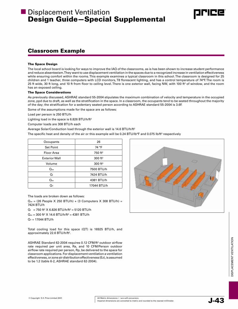
© Copyright E.H. Price Limited 2007. All Metric dimensions ( ) are soft conversion. Imperial dimensions are converted to metric and rounded to the nearest millimeter. J-43
DIS
PLA
CE
ME
NT
vE
NT
ILA
TIO
N
Displacement ventilationDesign Guide—Special Supplemental
Classroom Example
The Space Design
The local school board is looking for ways to improve the IAQ of the classrooms, as is has been shown to increase student performance and reduce absenteeism. They want to use displacement ventilation in the spaces due to a recognized increase in ventilation effectiveness while ensuring comfort within the rooms. This example examines a typical classroom in this school. The classroom is designed for 25 children and 1 teacher, three computers with LCD monitors, T8 florescent lighting, and has a control temperature of 74°F. The room is 25 ft wide, 30 ft long, and 10 ft from floor to ceiling level. There is one exterior wall, facing NW, with 100 ft² of window, and the room has an exposed ceiling.
The Space Considerations
As previously discussed, ASHRAE standard 55-2004 stipulates the maximum combination of velocity and temperature in the occupied zone, ppd due to draft, as well as the stratification in the space. In a classroom, the occupants tend to be seated throughout the majority of the day; the stratification for a sedentary seated person according to ASHRAE standard 55-2004 is 3.6F.
Some of the assumptions made for the space are as follows:
Load per person is 250 BTU/h
Lighting load in the space is 6.826 BTU/h/ft²
Computer loads are 308 BTU/h each
Average Solar/Conduction load through the exterior wall is 14.6 BTU/h/ft²
The specific heat and density of the air or this example will be 0.24 BTU/lb°F and 0.075 lb/ft³ respectively
Occupants 26
Set Point 74 °F
Floor Area 750 ft²
Exterior Wall 300 ft²
volume 300 ft³
Qoe 7500 BTU/h
Ql 7424 BTU/h
Qex 4381 BTU/h
QT 17044 BTU/h
The loads are broken down as follows:
Qoe = (26 People X 250 BTU/h) + (3 Computers X 308 BTU/h) = 7424 BTU/h
Ql = 750 ft² X 6.826 BTU/h/ft² = 5120 BTU/h
Qex = 300 ft² X 14.6 BTU/h/ft² = 4381 BTU/h
QT = 17044 BTU/h
Total cooling load for this space (QT) is 16925 BTU/h, and approximately 22.6 BTU/h/ft².
ASHRAE Standard 62-2004 requires 0.12 CFM/ft² outdoor airflow rate required per unit area, Ra, and 10 CFM/Person outdoor airflow rate required per person, Rp, be delivered to the space for classroom applications. For displacement ventilation a ventilation effectiveness, or zone air distribution effectiveness (Ez), is assumed to be 1.2 (table 6-2, ASHRAE standard 62-2004).

J-44 All Metric dimensions ( ) are soft conversion. © Copyright E.H. Price Limited 2007. Imperial dimensions are converted to metric and rounded to the nearest millimeter.
DIS
PLA
CE
ME
NT
vE
NT
ILA
TIO
N
Displacement ventilationDesign Guide—Special Supplemental
Classroom Example
Determine the Airflow Rate to meet the Cooling Load
Determine the Fresh Air Flow Rate and Breathing Zone Ventilation Effectiveness
Note that some local codes may not allow the discount for vE, or may have stricter requirements, and they should be used instead of this calculation. Example: Title 24 in California.
The total supply air volume is then the maximum value between vh and vr.
Calculate the Supply Air Temperature
Determine the Return Air Temperature
Selection of Diffusers
Because floor space is limited in a classroom, and wall space is typically covered with teaching material, either a ceiling mounted or corner mounted diffuser would be the ideal diffuser choice. As stated in previous examples, for comfort reasons, the diffusers for this space are limited to 40 fpm. With a supply air volume of 946 CFM and a face velocity of 40 fpm, 23.65 ft² of diffuser face is required. Three 30”x 42” DFIC corner diffusers will supply 946 CFM at 36.0 fpm, and occupants will need to be located at least 2 feet or more from the diffuser.

© Copyright E.H. Price Limited 2007. All Metric dimensions ( ) are soft conversion. Imperial dimensions are converted to metric and rounded to the nearest millimeter. J-45
DIS
PLA
CE
ME
NT
vE
NT
ILA
TIO
N
Classroom Example
Layout of the Classroom
The corner diffusers could be placed in any of the corners to supply this room, as long as the occupant is not within 2 feet of the diffuser face.
CFD Representation of the Space
A CFD analysis was run for this example using the conditions, calculated airflow and supply air temperature with the DF1C selected in the example for a visual representation of space dynamics.
Figure 75 shows the temperature profile in the space. The DF1C’s function as predicted and creates an even stratification in the space. The seated occupants are experiencing the desired set point and the stratification in the space is not outside the comfort criteria.
Figure 76 shows the temperature profile in the space with a isoplane showing the set point temperature of the space. All of the occupants are near or within the desired temperature, but at full load in the space, some over cooling may occur.
Figure 77 shows the velocity profile in the space. The DF1C’s produces a prominent air pattern predicted to be up to 60 feet per minute, shown in red on the floor.
Figure 78 shows the draft temperature profile in the space. The DF1C diffusers create the appropriate stratification in the space, but placement of the diffuser with respect to the occupants is critical. There is a prominent uncomfortable space directly in front of the diffusers.
Figure 75: Temperature Profile Figure 76: Temperature Profile with a 74º F Isoplane
Figure 77: Velocity Profile
Displacement ventilationDesign Guide—Special Supplemental
Figure 78: Draft Profile
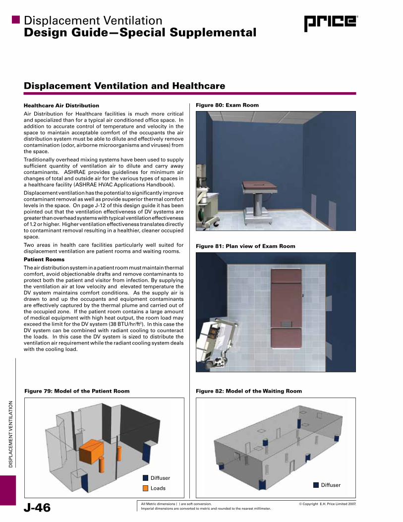
J-46 All Metric dimensions ( ) are soft conversion. © Copyright E.H. Price Limited 2007. Imperial dimensions are converted to metric and rounded to the nearest millimeter.
DIS
PLA
CE
ME
NT
vE
NT
ILA
TIO
N
Displacement ventilationDesign Guide—Special Supplemental
Displacement Ventilation and Healthcare
Healthcare Air Distribution
Air Distribution for Healthcare facilities is much more critical and specialized than for a typical air conditioned office space. In addition to accurate control of temperature and velocity in the space to maintain acceptable comfort of the occupants the air distribution system must be able to dilute and effectively remove contamination (odor, airborne microorganisms and viruses) from the space.
Traditionally overhead mixing systems have been used to supply sufficient quantity of ventilation air to dilute and carry away contaminants. ASHRAE provides guidelines for minimum air changes of total and outside air for the various types of spaces in a healthcare facility (ASHRAE HvAC Applications Handbook).
Displacement ventilation has the potential to significantly improve contaminant removal as well as provide superior thermal comfort levels in the space. On page J-12 of this design guide it has been pointed out that the ventilation effectiveness of Dv systems are greater than overhead systems with typical ventilation effectiveness of 1.2 or higher. Higher ventilation effectiveness translates directly to contaminant removal resulting in a healthier, cleaner occupied space.
Two areas in health care facilities particularly well suited for displacement ventilation are patient rooms and waiting rooms.
Patient Rooms
The air distribution system in a patient room must maintain thermal comfort, avoid objectionable drafts and remove contaminants to protect both the patient and visitor from infection. By supplying the ventilation air at low velocity and elevated temperature the Dv system maintains comfort conditions. As the supply air is drawn to and up the occupants and equipment contaminants are effectively captured by the thermal plume and carried out of the occupied zone. If the patient room contains a large amount of medical equipment with high heat output, the room load may exceed the limit for the Dv system (38 BTU/hr/ft2). In this case the Dv system can be combined with radiant cooling to counteract the loads. In this case the Dv system is sized to distribute the ventilation air requirement while the radiant cooling system deals with the cooling load.
Figure 79: Model of the Patient Room
Diffuser
Loads
Figure 82: Model of the Waiting Room
Diffuser
Figure 81: Plan view of Exam Room
Figure 80: Exam Room

© Copyright E.H. Price Limited 2007. All Metric dimensions ( ) are soft conversion. Imperial dimensions are converted to metric and rounded to the nearest millimeter. J-47
DIS
PLA
CE
ME
NT
vE
NT
ILA
TIO
N
Displacement ventilationDesign Guide—Special Supplemental
Displacement Ventilation and Healthcare
Test 1 2
Method Dv A Dv B
Supply CFM 190 190
Supply ACH 4 4
SA Temp 68 66
OP Temp 76 74
RA Temp 78 76
Air Velocity, FPM 10 to 67 10 to 40
PPD % 6 to 22 2 to 17
Vent Eff 1.4 1.3
Test 1 2 3
Method Dv Dv Dv
Supply CFM 80 80 80
Supply ACH 4 4 4
Outside Temp 91 0 -22
SA Temp 68 66 69
OP Temp 75 74 75
RA Temp 76 77 79
Air Velocity, FPM 10 to 25 12 to 20 12 to 28
PPD % 10 to 12 8 to 16 7 to 10
Vent Eff 1.3 1.1
Test 1 2 3
Method Dv Dv DvSupply CFM 1800 1200 900Supply ACH 12 8 6
SA Temp 65 64 65OP Temp 70 71 72RA Temp 74 74 76
Air Velocity, FPM 10 to 46 12 to 34 12 to 30PPD % 10 to 20 5 to 14 5 to 12
Table 9: Waiting Room Vent Eff
Table 6: Patient Room
Table 7: Exam Room
Table 8: Waiting Room Comfort
Test 1 2 3
Method Ceiling Dv Dv
Supply CFM 1800 1200 900
Vent Eff 0.9 1.1 1.0
Waiting Room
Waiting rooms pose a special challenge to the air distribution system. Occupancy in the room can vary greatly and the health status of the occupant is not known. People in the waiting area could be extremely infectious or on the other hand extremely susceptible to infection. Obviously infection control is a priority consideration of the air distribution system but comfort condition must also be maintained. Displacement ventilation is again ideally suited to this application. Fresh clear air is distributed directly to the occupants and contaminants removed with the thermal plumes. Unless seated directly in front of a displacement outlet occupants will also experience a high level of thermal comfort.
Mock-up Testing
Mock-up tests conducted in the Price Laboratory in co-operation with Stantec Consulting Ltd and Mazzetti & Associates support the application of displacement ventilation in hospital patient and waiting rooms. Three rooms were mocked-up and run at several conditions to determine comfort and ventilation effectiveness. Comfort was determined by Percent of People Dissatisfied (PPD) as defined by ASHRAE Standard 55. A PPD value less than 20 is deemed acceptable. For a detailed report of the Healthcare Air Distribution Mock-up contact your Price representative.
1. Patient Room:
Figure 79 illustrates the room layout which included an exterior window simulated with an environmental chamber and two Dv outlet locations. Table 6 demonstrates excellent ventilation effectiveness for both outlet locations even at ACHs below current code requirements. Outlet location B provides superior comfort as it is further away from the occupants.
2. Exam Room:
Figures 80 & 81 illustrate the room layout which included an exterior window simulated with an environmental chamber and radiant ceiling panels for supplemental heating and cooling. Tests were run at several outside temperature conditions. Table 7 demonstrates excellent ventilation effectiveness at all conditions, even at ACHs below current code requirements. By comparison, overhead mixing systems usually are limited to a ventilation effectiveness of 0.8 – 0.9 when operating in the heating mode. In all modes of operation, acceptable comfort conditions were maintained.
3. Waiting Room:
Figure 82 illustrates the room layout and outlet location. Table 8 confirms that comfort is maintained even with air change rates as high as 12. Table 9 illustrates ventilation effectiveness values for the Dv system are superior to overhead mixing even at lower air change rates.

J-48 All Metric dimensions ( ) are soft conversion. © Copyright E.H. Price Limited 2007. Imperial dimensions are converted to metric and rounded to the nearest millimeter.
DIS
PLA
CE
ME
NT
vE
NT
ILA
TIO
N
Displacement ventilationDesign Guide—Special Supplemental
Displacement Ventilation and Healthcare
Figure 83: Temperature Profile with overhead air distribution
Figure 84: Temperature Profile with displacement ventilation
Figure 85: Velocity Profile with displacement ventilation Figure 86: Velocity Profile with overhead air distribution
CFD Analysis
The test data gathered from the Laboratory mock-up was used to create CFD models of the space. Figure 83 is the output for the CFD simulation of the patient room example at the cooling design conditions with overhead air distribution. Figure 84 illustrates the temperature profile of the patient room with Dv. A distinct stratification is observed with warmer temperatures at the ceiling. Temperatures in the occupied zone are in the 70° - 74ºF comfort range. Any lighter than air contaminants would be concentrated in the higher warm air layer. By contrast the overhead system (Figure 83) produces a fairly uniform temperature distribution as expected. Figure 85 illustrates the velocity profile of the patient room with Dv. Generally velocities in the space are less than 20fpm (0.33 fps). The overhead system (Figure 86) demonstrates higher velocities under the diffuser illustrating the induction of room air as well as some higher velocities projecting down the far wall.

© Copyright E.H. Price Limited 2007. All Metric dimensions ( ) are soft conversion. Imperial dimensions are converted to metric and rounded to the nearest millimeter. J-49
DIS
PLA
CE
ME
NT
vE
NT
ILA
TIO
N
Displacement ventilationDesign Guide
References
1. 2001 ASHRAE Fundamentals Handbook, Space Air Diffusion, Chapter 32.11
2. Hakon Skistad, Displacement ventilation, 1994, Control of the Built Environment series; 1, John Wiley & Sons Inc., England.
3. Hakon Skistad, Elisabeth Mundt, Peter Nielsen, Kim Hagstrom, and Jorma Railio,
Displacement ventilation in Non-Industrial Premises, Rehva Guidebook No 1, Federation of European Heating and Air Conditioning Associations, 2002.
4. Qingyan Chen and Leon Glicksman, Performance Evaluation and Development of Design Guidelines for Displacement ventilation, Final Report to ASHRAE on Research Project RP-949.
5. Shiping Hu, Qingyan Chen, Leon Glicksman, Comparison of Energy Consumption between Displacement and Mixing ventilation Systems for Different U.S. Buildings and Climates, ASHRAE Transactions 1999, v. 105, Pt. 2.
6. Xiaoxiong Yuan, Qingyan Chen and Leon Glucksman, A Critical Review of Displacement ventilation, ASHRAE Transactions 1998 v. 104, Pt. 1.
7. Xiaoxiong Yuan, Qingyan Chen and Leon Glucksman, Performance Evaluation and Design Guidelines for Displacement ventilation, ASHRAE Transactions 1999, v. 105, Pt.1.
8. U.S. Green Building Council, LEEDTM (Leadership in Energy & Environmental Design) - Green Building Rating System for New Construction & Major Renovations (LEED-NC) version 2.1, November 2002 - revised 3/14/03, www.usbgc.com/leed.
9. ASHRAE Standard 62.
10. Qingyan Chen and Leon Glicksman, “System Performance Evaluation and Design Guidelines for Displacement ventilation”, ASHRAE, Inc, 2003.
11. ASHRAE Standard 55.
12. Pawel Wargocki and David Wyon, Research Report on effects of HvAC on Student Peformance, ASHRAE Journal, vol 48, No. 10, 2006.
13. Morton Blatt, Advanced HvAC Systems for Improving Indoor Environmental Quality and Energy Performance of California K-12 Schools: Applications Guide for Off-the-Shelf Equipment for Displacement ventilation Use Consultant Report prepared for California Energy Commission, 2006.
14. Gregory Kats, Greening America’s Schools, Costs and Benefits, Capital E Report, October 2006.
J-50 All Metric dimensions ( ) are soft conversion. © Copyright E.H. Price Limited 2007. Imperial dimensions are converted to metric and rounded to the nearest millimeter.
DIS
PLA
CE
ME
NT
vE
NT
ILA
TIO
N
notes
Underfloor Air DistributionDesign Guide


® Price is a registered trademark of E.H. Price Limited. © 2007. Printed in Canada 2007
www.pr ice-hvac . com
Your Local Price Representative:
P R I C E A I R D I S T R I B U T I O N P R O D U C T S F O R W O R L D C L A S S C I T I E S
Printed on Recycled Material using vegetable-based, low VOC inks
2975 Shawnee Ridge CourtSuwanee, Georgia USA 30024Ph: 770.623.8050 Fax: 770.623.6404
I N T H E U N I T E D S T A T E S
• US Head Office, Price Technical Center, Export Sales Office & Manufacturing Facilities in Atlanta, Georgia
• Representation in major US cities
• Manufacturing Facilities & Price Technical Center West in Phoenix, Arizona
• Representation in major US cities
• Canadian Head Office, Laboratory & Manufacturing Facilities in Winnipeg, Manitoba
• Sales Offices or Representation in all major Canadian cities
638 Raleigh StreetWinnipeg, Manitoba Canada R2K 3Z9Ph: 204.669.4220 Fax: 204.663.2715
999 North Thornton RoadCasa Grande, Arizona USA 85222-3809
I N T H E U N I T E D S T A T E S
I N C A N A D A
Product Improvement is a continuing endeavor at Price. Therefore, specifications are subject to change without notice. Consult your Price sales representative for current specifications or more detailed information.
The founding principles of our company have never changed - business integrity, first class service and a commitment to people. Price manufacturing endeavors arose from our belief that we could supply superior products and services at a reasonable price. Our mission is to become the worldwide supplier of preference for air distribution products and services. You can rely on Price – our products and services – with confidence.
Warranty: The Company warrants and guarantees that all goods within this catalog that have been manufactured by the Company have been manufactured in accordance with the specifications published herein and will be free from defects in material and workmanship for a period of twelve (12) months from the date of Bill of Lading issued by the Company. The Company will replace defective product at its option, but will not be responsible for labor or material charges in replacing product or consequential damages. Any installation not conforming with the Company's specifications, manuals, bulletins or instructions or any misuse or any modification not authorized by the Company voids this warranty. This warranty is in lieu of all Provincial, State, and Federal statutory warranties and the conditions herein are in substitution and replacement of such warranties, statutory or otherwise.


