Embed Size (px)
Citation preview
Agenda
• Introduction to Wireless Power
• WPC – The Wireless Power Consortium
• bqTESLATM Solutions from Texas Instruments
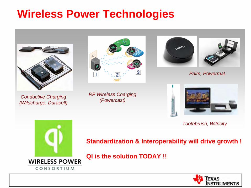
Wireless Power Technologies
Conductive Charging(Wildcharge, Duracell)
RF Wireless Charging (Powercast)
Toothbrush, Witricity
Palm, Powermat
Standardization & Interoperability will drive growth !
QI is the solution TODAY !!
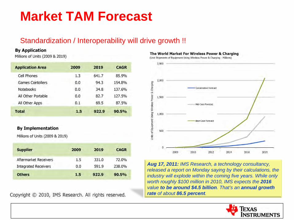
Market TAM Forecast
Aug 17, 2011: IMS Research, a technology consultancy, released a report on Monday saying by their calculations, the industry will explode within the coming five years. While only worth roughly $100 million in 2010, IMS expects the 2016 value to be around $4.5 billion. That’s an annual growth rate of about 86.5 percent.
Standardization / Interoperability will drive growth !!
WIRELESS POWERC O N S O R T I U M
iPhone
3G/3GS case
iPhone
4
sleeve
BB8900
Curve door
2‐device
charge pad
LG
Revolution™
Motorola
DROID™
3
Samsung DROID ™
CHARGE
HTC
ThunderBolt™
HTC Incredible 2™
Verizon (LG)
charge pad
Pantech
Breakout
Motorola
DROID ™ Bionic
HTC Rezound™
Motorola
DROID ™ 4
LG Lucid™
NEC MEDIA™
PP N‐01D
ARROWS Kiss™
F‐03D
Sharp STYLE SH‐05D
Eluga™
V P‐06D
QE‐TM101
Sharp AQUOS™
SH‐02D
Sharp AQUOS™
f‐SH13C
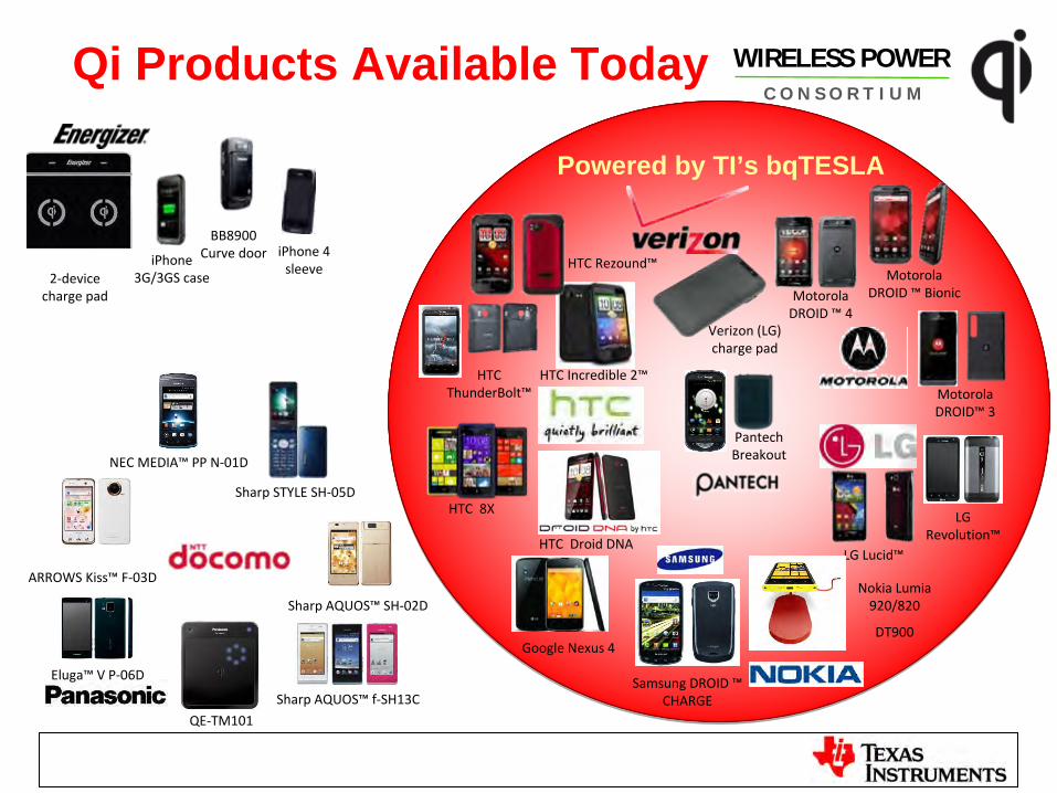
Qi Products Available Today
Powered by TI’s bqTESLA
HTC
8X
HTC
Droid DNA
Google Nexus 4
Nokia Lumia
920/820
DT900
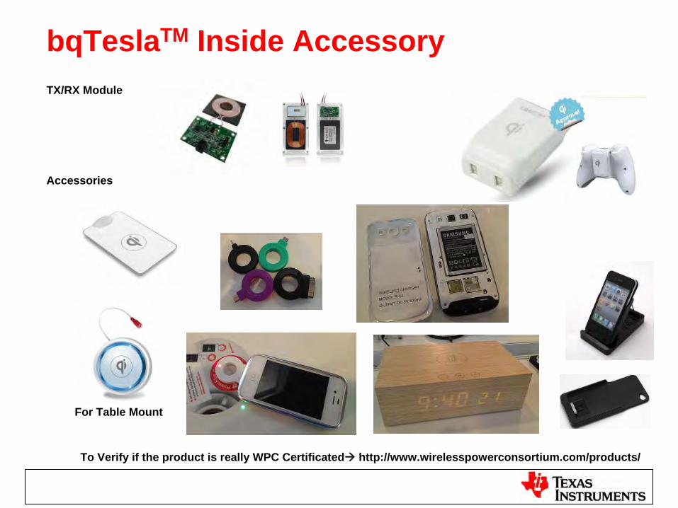
bqTeslaTM Inside AccessoryTX/RX Module
Accessories
To Verify if the product is really WPC Certificated http://www.wirelesspowerconsortium.com/products/
For Table Mount
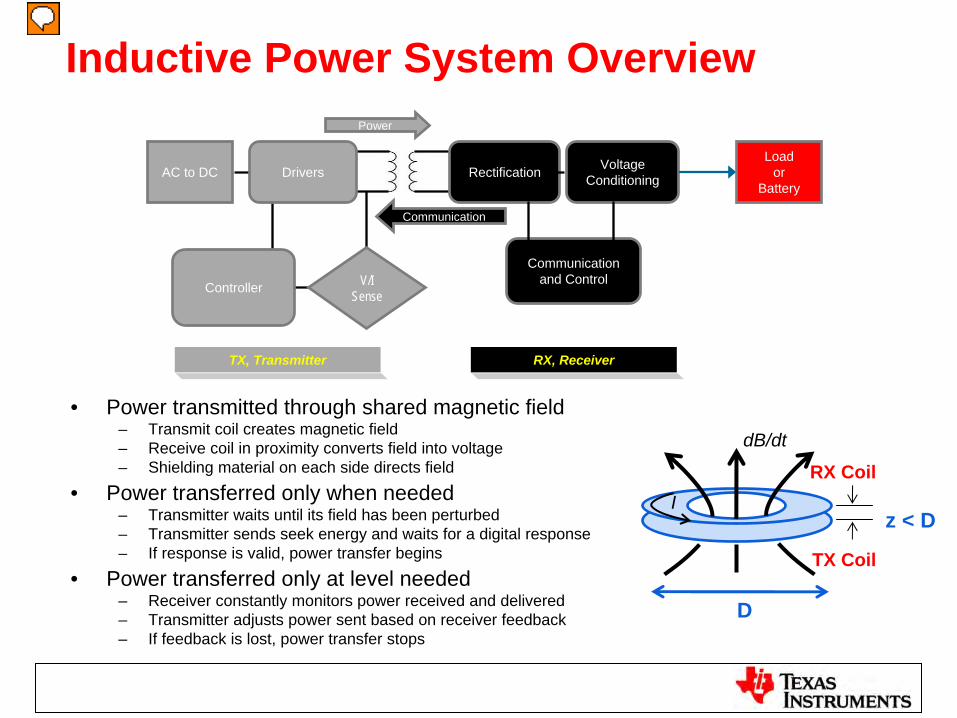
Inductive Power System Overview
• Power transmitted through shared magnetic field– Transmit coil creates magnetic field– Receive coil in proximity converts field into voltage– Shielding material on each side directs field
• Power transferred only when needed– Transmitter waits until its field has been perturbed– Transmitter sends seek energy and waits for a digital response– If response is valid, power transfer begins
• Power transferred only at level needed– Receiver constantly monitors power received and delivered– Transmitter adjusts power sent based on receiver feedback– If feedback is lost, power transfer stops
dB/dt
Iz < D
D
TX Coil
RX Coil
AC to DC VoltageConditioning
Communication and Control
RectificationDriversLoad
orBattery
Controller V/ISense
Power
TX, Transmitter RX, Receiver
Communication
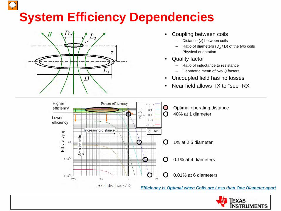
System Efficiency Dependencies• Coupling between coils
– Distance (z) between coils– Ratio of diameters (D2 / D) of the two coils– Physical orientation
• Quality factor– Ratio of inductance to resistance– Geometric mean of two Q factors
• Uncoupled field has no losses• Near field allows TX to “see” RX
40% at 1 diameter
1% at 2.5 diameter
0.1% at 4 diameters
0.01% at 6 diameters
Optimal operating distance
Efficiency is Optimal when Coils are Less than One Diameter apart
Higher efficiency
Lowerefficiency
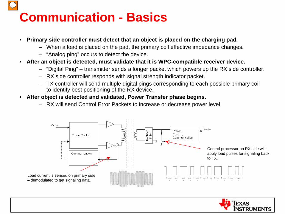
Communication - Basics• Primary side controller must detect that an object is placed on the charging pad.
– When a load is placed on the pad, the primary coil effective impedance changes.– “Analog ping” occurs to detect the device.
• After an object is detected, must validate that it is WPC-compatible receiver device.– “Digital Ping” – transmitter sends a longer packet which powers up the RX side controller.– RX side controller responds with signal strength indicator packet.– TX controller will send multiple digital pings corresponding to each possible primary coil
to identify best positioning of the RX device.• After object is detected and validated, Power Transfer phase begins.
– RX will send Control Error Packets to increase or decrease power level
VOUT , IOUT
Load current is sensed on primary side – demodulated to get signaling data.
Control processor on RX side will apply load pulses for signaling back to TX.
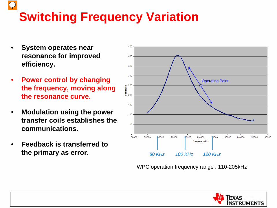
Switching Frequency Variation
• System operates near resonance for improved efficiency.
• Power control by changing the frequency, moving along the resonance curve.
• Modulation using the power transfer coils establishes the communications.
• Feedback is transferred to the primary as error. 80 KHz 100 KHz 120 KHz
Operating Point
WPC operation frequency range : 110-205kHz
Metal Object SENSING and PROTECTING• Metal between TX and RX
– Metal cover should not exist between TX & RX in design– Protection for User accidently case is needed – Energy Lost in Foreign Metals (Eddy Current) – Undesired Heating and Safety Issue
• Two methods to detect foreign object via monitoring power lossesPMOD (TI only, Parasitic Metal Object Detection)
– A quadratic polynomial approximation based on the Rectified Power on Rx to calculate losses in the TX-RX system.
FOD (MUST in WPC1.1 , Foreign Object Detection)– This uses specific information from characterized Rx to improve the
accuracy of Foreign Object Detection in WPC system (looking at Received Power from Rx, and power lost in shield, coil, rectifier and control circuit).
– FOD is finalized in WPC 1.1 spec. TI solution will move to FOD (from PMOD) instead of using PMOD.
WPCWireless Power Consortium

14
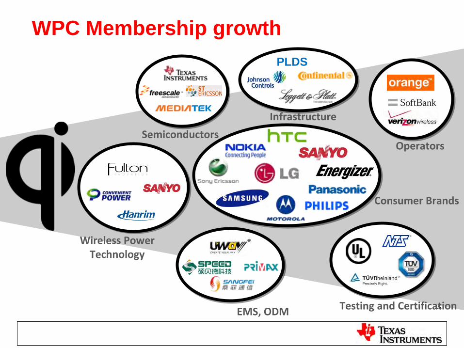
WPC Membership growth
15
Semiconductors
Wireless PowerTechnology
EMS, ODM Testing and Certification
Infrastructure
Operators
Consumer Brands
PLDS
15
WPC - Wireless Power Consortium• History
– http://www.wirelesspowerconsortium.com/– Held its first meeting on Dec-18, 2008 in Hong Kong.– Published the Qi low power specification in Aug 2009, 18 months after the first meeting.
The first product was certified in Sep 2009.
• Today, WPC1.1 now– WPC today define low power applications (<5W).– Annual fee is US$ 15k/20k for join Associated/Regular membership– 141 members, 133 certificated products (As of Jan-30, 2013) – The Consortium is working on
• 10W-15W extension• 120W medium power• 2kW, wireless power in Kitchen
• Membership & QI Certification– WPC Spec. Part 1 Specification is open for public download. – Part 2 & 3 (Performance & Compliance) only limited to member access.– WPC Lab only accept members’ product for certification.
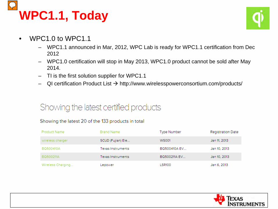
WPC1.1, Today• WPC1.0 to WPC1.1
– WPC1.1 announced in Mar, 2012, WPC Lab is ready for WPC1.1 certification from Dec 2012
– WPC1.0 certification will stop in May 2013, WPC1.0 product cannot be sold after May 2014.
– TI is the first solution supplier for WPC1.1– QI certification Product List http://www.wirelesspowerconsortium.com/products/
Free Positioning(Moving Coil)
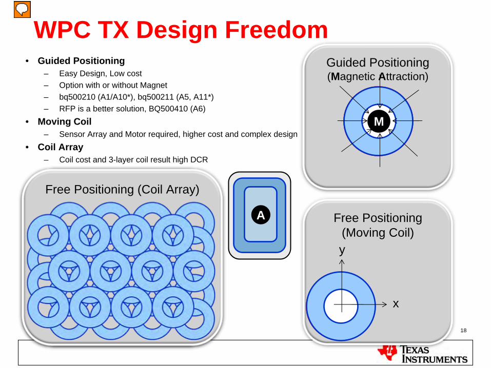
WPC TX Design Freedom
30 January 2013 18
Free Positioning (Coil Array)
Guided Positioning(Magnetic Attraction)
M
x
y
Free Positioning (Coil Array)
A
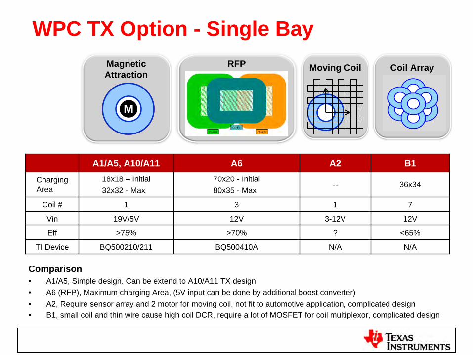
• Guided Positioning– Easy Design, Low cost– Option with or without Magnet– bq500210 (A1/A10*), bq500211 (A5, A11*)– RFP is a better solution, BQ500410 (A6)
• Moving Coil– Sensor Array and Motor required, higher cost and complex design
• Coil Array– Coil cost and 3-layer coil result high DCR
WPC TX Option - Single BayMoving Coil Coil Array
M
Magnetic Attraction
RFP
A1/A5, A10/A11 A6 A2 B1
Charging Area
18x18 – Initial32x32 - Max
70x20 - Initial80x35 - Max
-- 36x34
Coil # 1 3 1 7
Vin 19V/5V 12V 3-12V 12V
Eff >75% >70% ? <65%
TI Device BQ500210/211 BQ500410A N/A N/A
Comparison• A1/A5, Simple design. Can be extend to A10/A11 TX design• A6 (RFP), Maximum charging Area, (5V input can be done by additional boost converter) • A2, Require sensor array and 2 motor for moving coil, not fit to automotive application, complicated design• B1, small coil and thin wire cause high coil DCR, require a lot of MOSFET for coil multiplexor, complicated design
bqTESLATM Solutions
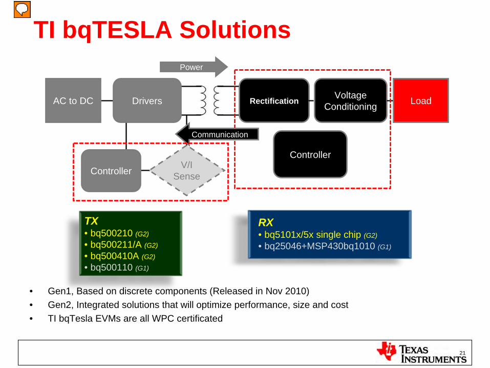
TI bqTESLA Solutions
AC to DC VoltageConditioning
Controller
RectificationDrivers Load
Controller V/ISense
Power
Communication
RX • bq5101x/5x single chip (G2)
• bq25046+MSP430bq1010 (G1)
TX• bq500210 (G2)
• bq500211/A (G2)
• bq500410A (G2)
• bq500110 (G1)
21
• Gen1, Based on discrete components (Released in Nov 2010)• Gen2, Integrated solutions that will optimize performance, size and cost• TI bqTesla EVMs are all WPC certificated
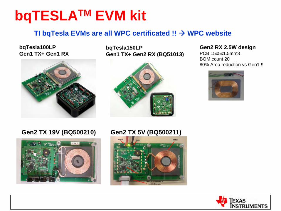
bqTESLATM EVM kit
bqTesla100LPGen1 TX+ Gen1 RX
bqTesla150LPGen1 TX+ Gen2 RX (BQ51013)
Gen2 RX 2.5W designPCB 15x5x1.5mm3BOM count 2080% Area reduction vs Gen1 !!
Gen2 TX 19V (BQ500210)
TI bqTesla EVMs are all WPC certificated !! WPC website
Gen2 TX 5V (BQ500211)
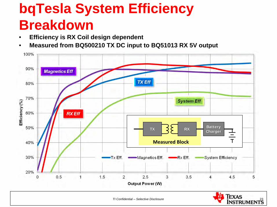
bqTesla System Efficiency Breakdown• Efficiency is RX Coil design dependent• Measured from BQ500210 TX DC input to BQ51013 RX 5V output
TI Confidential – Selective Disclosure 23
TXTX RXRX BatteryBatteryChargerCharger
Measured Block
bqTESLATM RX
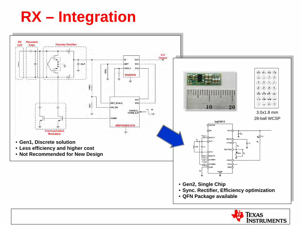
RX – Integration
• Gen1, Discrete solution• Less efficiency and higher cost• Not Recommended for New Design
• Gen2, Single Chip• Sync. Rectifier, Efficiency optimization• QFN Package available
3.0x1.8 mm28-ball WCSP
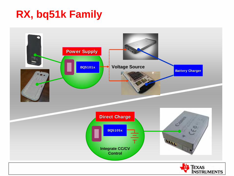
RX, bq51k Family
Voltage Source
Power SupplyPower Supply
BQ5101xBQ5101xBattery ChargerBattery Charger
BQ5105xBQ5105x
Direct ChargeDirect Charge
Integrate CC/CV Control
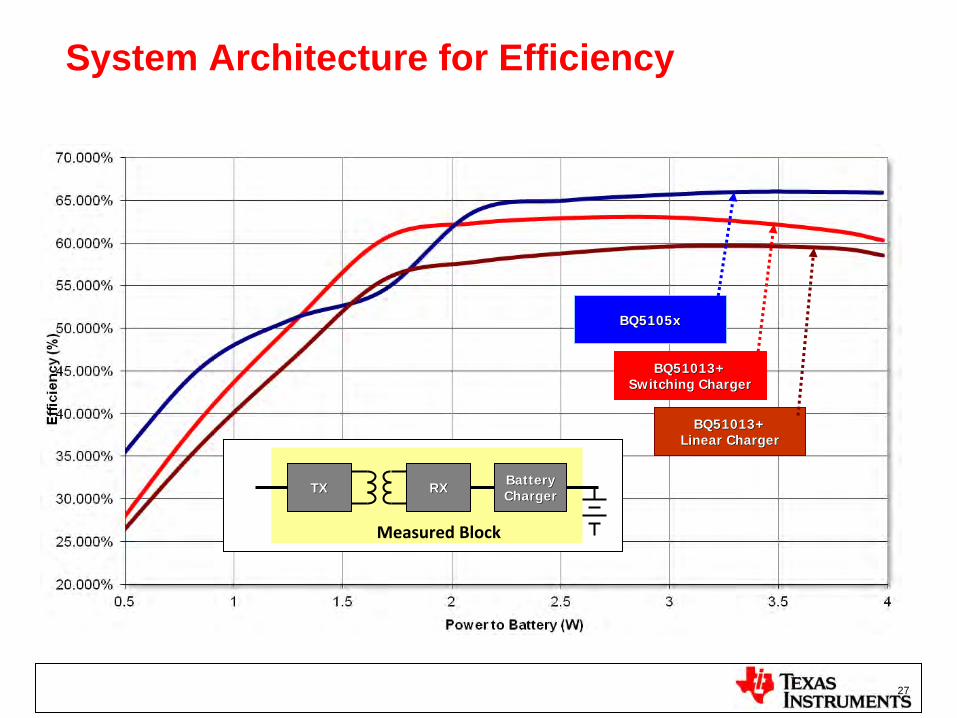
System Architecture for Efficiency
27
BQ5105xBQ5105x
BQ51013+BQ51013+Linear ChargerLinear Charger
BQ51013+BQ51013+Switching ChargerSwitching Charger
TXTX RXRX BatteryBatteryChargerCharger
Measured Block
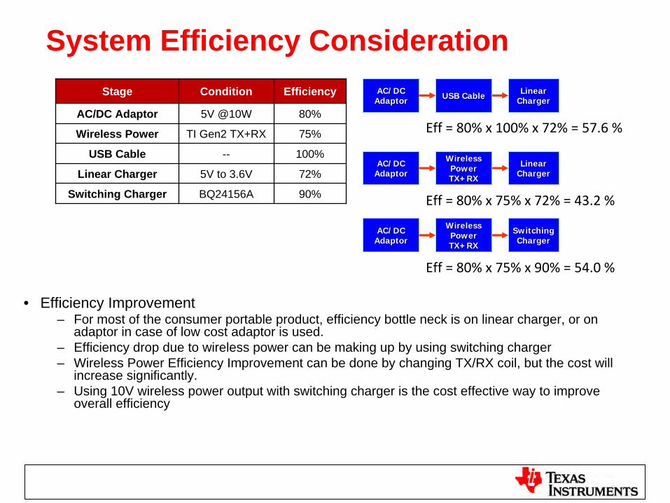
System Efficiency Consideration
Eff
= 80% x 75% x 72% = 43.2 %
Stage Condition Efficiency
AC/DC Adaptor 5V @10W 80%
Wireless Power TI Gen2 TX+RX 75%
USB Cable -- 100%
Linear Charger 5V to 3.6V 72%
Switching Charger BQ24156A 90%
AC/DCAC/DCAdaptorAdaptor USB CableUSB Cable LinearLinear
ChargerCharger
Eff
= 80% x 100% x 72% = 57.6 %
AC/DCAC/DCAdaptorAdaptor
WirelessWirelessPowerPowerTX+RXTX+RX
LinearLinearChargerCharger
AC/DCAC/DCAdaptorAdaptor
WirelessWirelessPowerPowerTX+RXTX+RX
SwitchingSwitchingChargerCharger
Eff
= 80% x 75% x 90% = 54.0 %
• Efficiency Improvement– For most of the consumer portable product, efficiency bottle neck is on linear charger, or on
adaptor in case of low cost adaptor is used. – Efficiency drop due to wireless power can be making up by using switching charger– Wireless Power Efficiency Improvement can be done by changing TX/RX coil, but the cost will
increase significantly.– Using 10V wireless power output with switching charger is the cost effective way to improve
overall efficiency
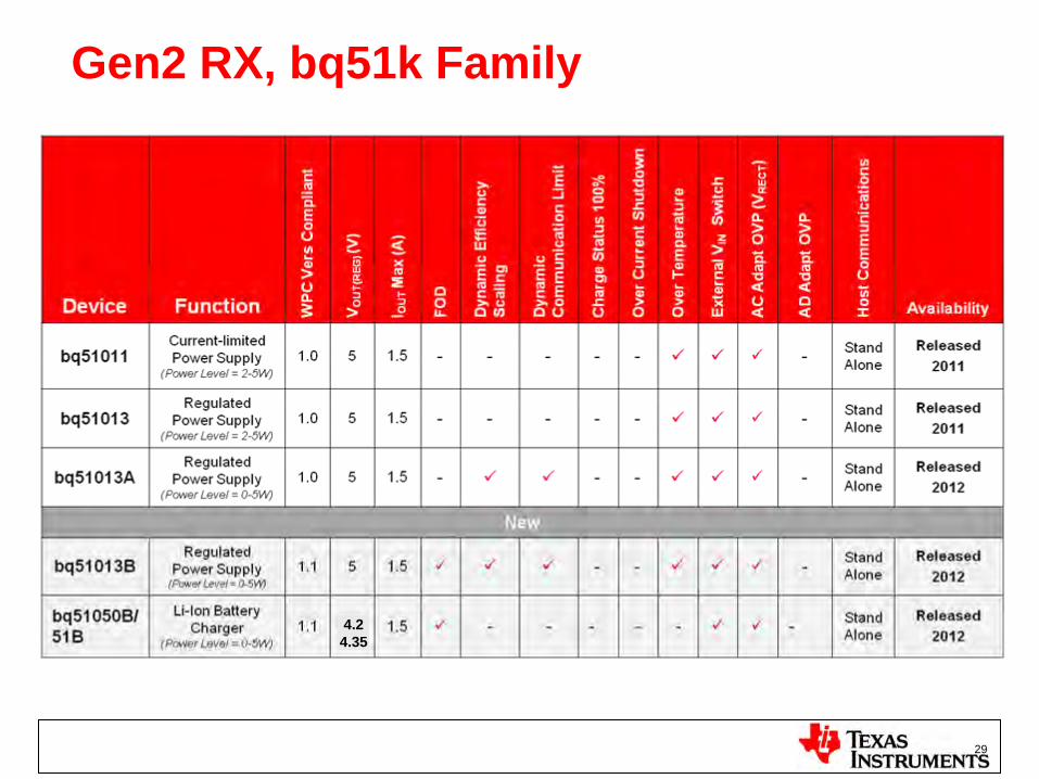
Gen2 RX, bq51k Family
29
4.24.35
SYSTEM
Status
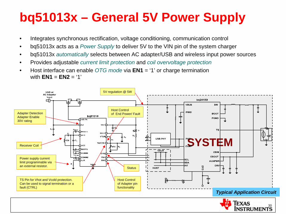
bq51013x – General 5V Power Supply• Integrates synchronous rectification, voltage conditioning, communication control • bq51013x acts as a Power Supply to deliver 5V to the VIN pin of the system charger• bq51013x automatically selects between AC adapter/USB and wireless input power sources• Provides adjustable current limit protection and coil overvoltage protection• Host interface can enable OTG mode via EN1 = ‘1’ or charge termination
with EN1 = EN2 = ‘1’
Adapter DetectionAdapter Enable30V rating
Receiver Coil
Host Controlof Adapter pinfunctionality
Host Controlof End Power/ Fault
5V regulation @ 5W
TS Pin for Vhot and Vcold protection. Can be used to signal termination or a fault (CTRL)
Power supply current limit programmable via an external resistor.
30
Typical Application Circuit
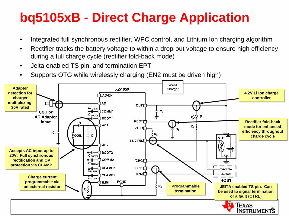
bq5105xB - Direct Charge Application• Integrated full synchronous rectifier, WPC control, and Lithium Ion charging algorithm• Rectifier tracks the battery voltage to within a drop-out voltage to ensure high efficiency
during a full charge cycle (rectifier fold-back mode)• Jeita enabled TS pin, and termination EPT• Supports OTG while wirelessly charging (EN2 must be driven high)
Adapter detection for
charger multiplexing.
30V rated
Adapter detection for
charger multiplexing.
30V rated
Accepts AC input up to 20V. Full synchronous
rectification and OV protection via CLAMP
Accepts AC input up to 20V. Full synchronous
rectification and OV protection via CLAMP
Charge current programmable via
an external resistor
Charge current programmable via
an external resistor JEITA enabled TS pin. Can be used to signal termination
or a fault (CTRL)
JEITA enabled TS pin. Can be used to signal termination
or a fault (CTRL)
Programmable termination
Programmable termination
Rectifier fold-back mode for enhanced
efficiency throughout charge cycle
Rectifier fold-back mode for enhanced
efficiency throughout charge cycle
4.2V Li Ion charge controller
4.2V Li Ion charge controller
31
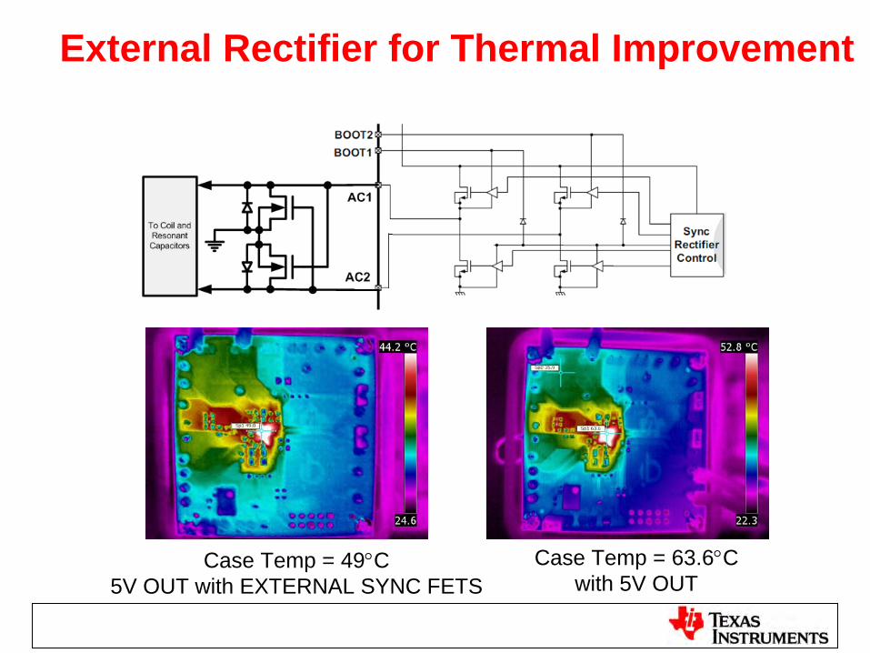
External Rectifier for Thermal Improvement
Case Temp = 49C5V OUT with EXTERNAL SYNC FETS
Case Temp = 63.6Cwith 5V OUT

bqTESLATM TX
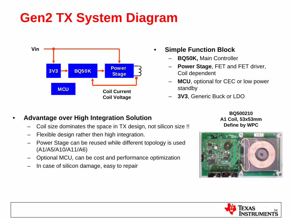
Gen2 TX System Diagram
34
BQ50KBQ50K Power Power StageStage3V33V3
MCUMCU
Vin
Coil CurrentCoil Voltage
• Advantage over High Integration Solution– Coil size dominates the space in TX design, not silicon size !! – Flexible design rather then high integration.– Power Stage can be reused while different topology is used
(A1/A5/A10/A11/A6)– Optional MCU, can be cost and performance optimization– In case of silicon damage, easy to repair
• Simple Function Block– BQ50K, Main Controller– Power Stage, FET and FET driver,
Coil dependent– MCU, optional for CEC or low power
standby– 3V3, Generic Buck or LDO
BQ500210A1 Coil, 53x53mm
Define by WPC
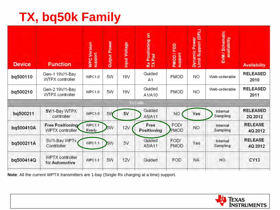
TX, bq50k Family
Note: All the current WPTX transmitters are 1-bay (Single Rx charging at a time) support.
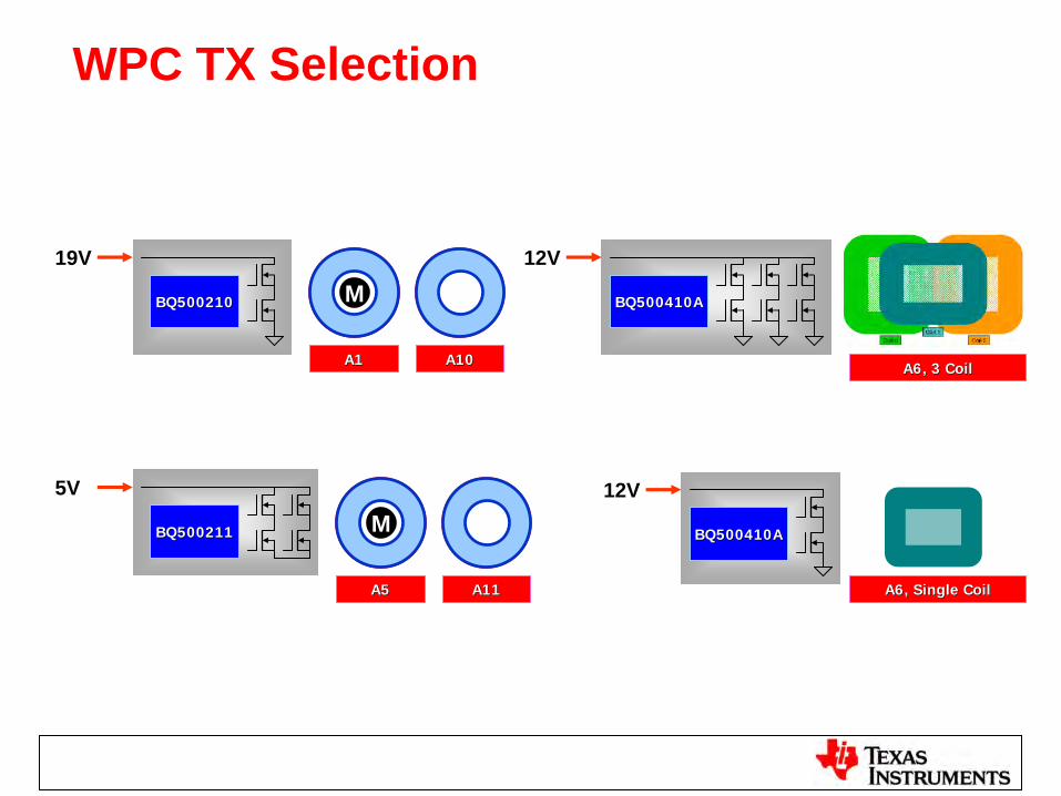
WPC TX Selection
MBQ500210BQ500210
19V
MBQ500211BQ500211
5V
BQ500410ABQ500410A
12V
BQ500410ABQ500410A
12V
A1A1 A10A10
A5A5 A11A11
A6, 3 CoilA6, 3 Coil
A6, Single CoilA6, Single Coil
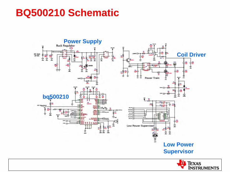
BQ500210 Schematic
Power Supply
Coil Driver
Low Power Supervisor
bq500210
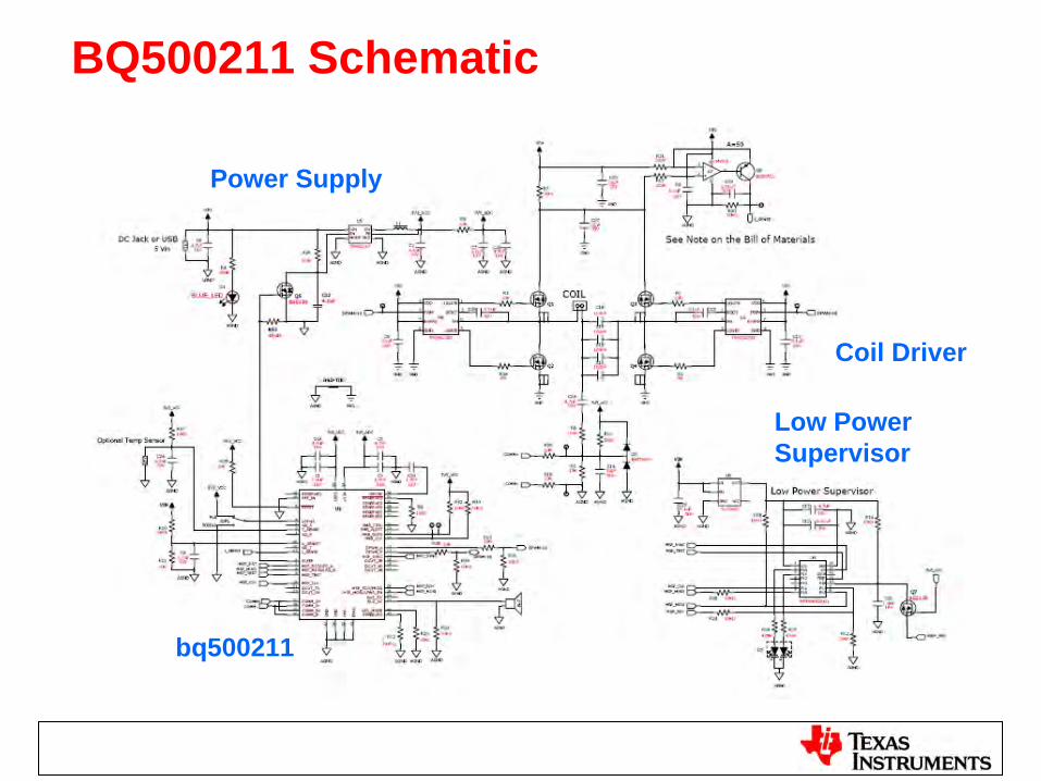
BQ500211 Schematic
Power Supply
Coil Driver
Low Power Supervisor
bq500211
bq500211 – Dynamic Power LimitTM
Operating from USB Port or Low Input Power Adapter
• For Qi Certification and WPC Compliance, Transmitter must be certified with a ~7W Transmitter
• A 5V Transmitter will allow operation from other popular adapters- USB Ports- Low Power Adapters (<7W)
• Latest WPC Spec recognizes operation from lower power ports- Need to notify user that “Full 5W Capability” is not available
• bq500211 features “Dynamic Power LimitTM”- Limits output current to ensure Input Supply not pulled down- Optional 500mA Current Limit, limits peak o/p current for USB compliant systems- Activates LED to indicate ‘Non WPC/Restricted Power’ operation
• Some Receivers may not be able to take advantage of DPLTM
- ie, Rx send EPT due to not enough power, or no ‘Input DPM on Charger’
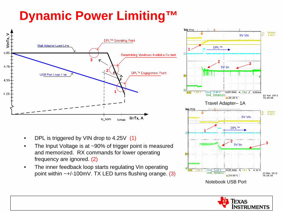
Dynamic Power Limiting™
• DPL is triggered by VIN drop to 4.25V (1)• The Input Voltage is at ~90% of trigger point is measured
and memorized. RX commands for lower operating frequency are ignored. (2)
• The inner feedback loop starts regulating Vin operating point within ~+/-100mV. TX LED turns flushing orange. (3)
VinT
x, V
1
2
3
Notebook USB Port
Travel Adapter– 1A
3
1
1
3
2
2
5V Vin
5V Iin
DPL™
5V Vin
DPL™
5V Iin
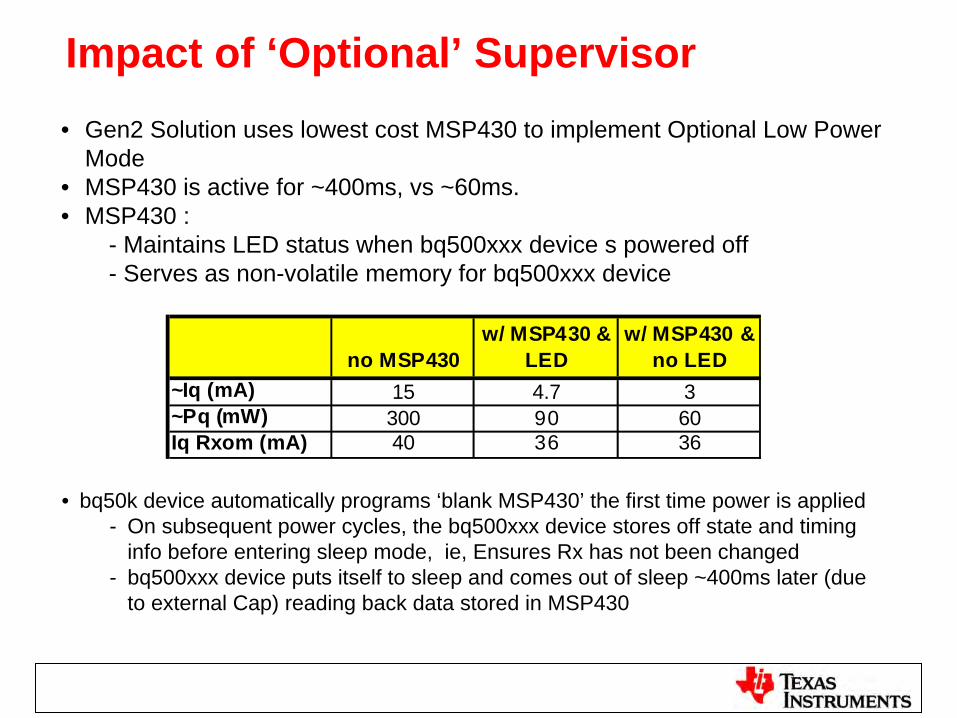
Impact of ‘Optional’ Supervisor• Gen2 Solution uses lowest cost MSP430 to implement Optional Low Power
Mode• MSP430 is active for ~400ms, vs ~60ms. • MSP430 :
- Maintains LED status when bq500xxx device s powered off- Serves as non-volatile memory for bq500xxx device
• bq50k device automatically programs ‘blank MSP430’ the first time power is applied- On subsequent power cycles, the bq500xxx device stores off state and timing
info before entering sleep mode, ie, Ensures Rx has not been changed- bq500xxx device puts itself to sleep and comes out of sleep ~400ms later (due
to external Cap) reading back data stored in MSP430
no MSP430w/ MSP430 &
LEDw/ MSP430 &
no LED~Iq (mA) 15 4.7 3~Pq (mW) 300 90 60Iq Rxom (mA) 40 36 36
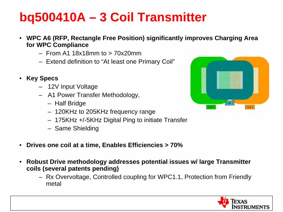
bq500410A – 3 Coil Transmitter• WPC A6 (RFP, Rectangle Free Position) significantly improves Charging Area
for WPC Compliance– From A1 18x18mm to > 70x20mm– Extend definition to “At least one Primary Coil”
• Key Specs– 12V Input Voltage– A1 Power Transfer Methodology,
– Half Bridge– 120KHz to 205KHz frequency range– 175KHz +/-5KHz Digital Ping to initiate Transfer– Same Shielding
• Drives one coil at a time, Enables Efficiencies > 70%
• Robust Drive methodology addresses potential issues w/ large Transmitter coils (several patents pending)
– Rx Overvoltage, Controlled coupling for WPC1.1, Protection from Friendly metal
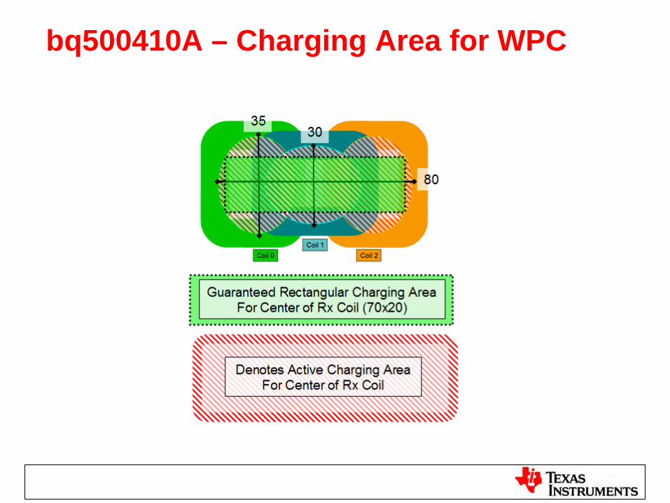
bq500410A – Charging Area for WPC
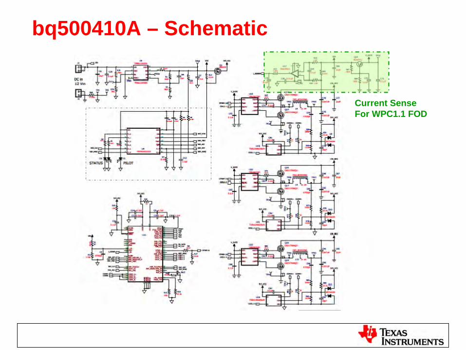
bq500410A – Schematic
Current SenseFor WPC1.1 FOD
45
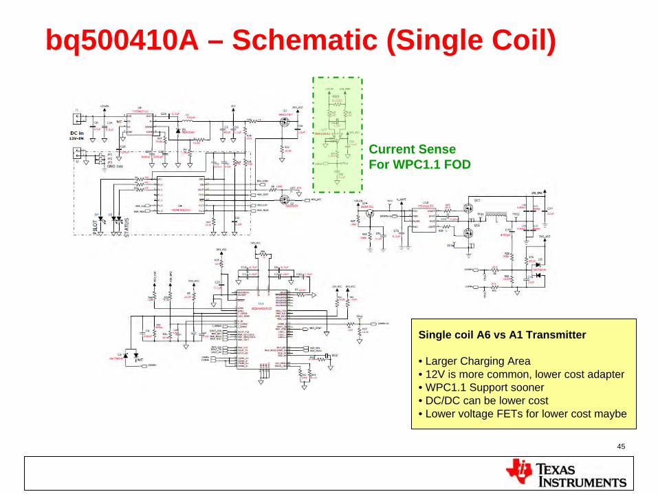
bq500410A – Schematic (Single Coil)
Single coil A6 vs A1 Transmitter
• Larger Charging Area• 12V is more common, lower cost adapter• WPC1.1 Support sooner• DC/DC can be lower cost• Lower voltage FETs for lower cost maybe
Current SenseFor WPC1.1 FOD
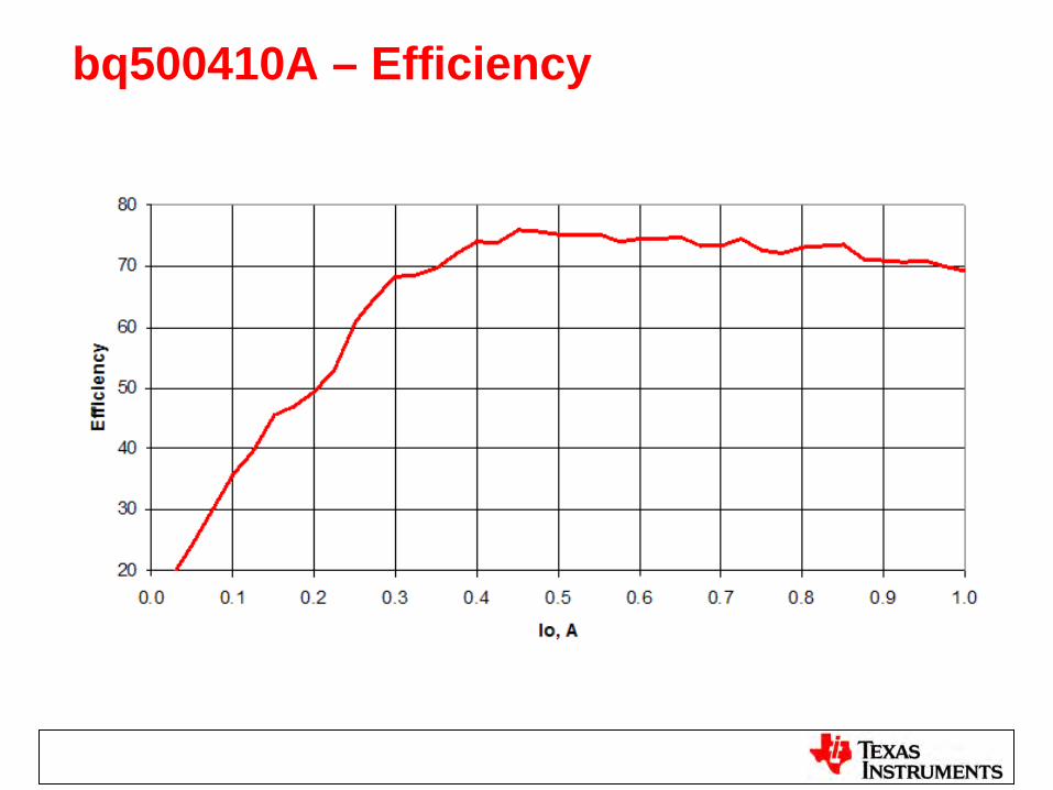
bq500410A – Efficiency
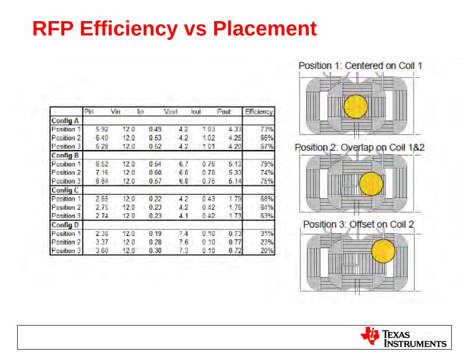
RFP Efficiency vs Placement
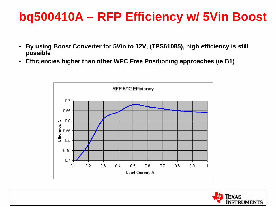
bq500410A – RFP Efficiency w/ 5Vin Boost
• By using Boost Converter for 5Vin to 12V, (TPS61085), high efficiency is still possible
• Efficiencies higher than other WPC Free Positioning approaches (ie B1)
bq500410A – Advantages Summary
• Excellent Free Positioning Area: >20mm x 70mm
• Drives just one coil at a time (A1 drive) – simpler circuit and >70% efficiency
• No Holes in Charging Area
• No Magnet
• Potential to build 5Vinput version– Today: using 5V to 12V Boost, while still >65% Efficiency
• WPC approved as new Transmitter type – A6
• Release Nov 2012
TX Design Consideration• Design from Silicon
– TI EVM had pass QI certification, Suggest to follow reference design for the first build
– 4 layer PCB design is required– Use C0G type for the resonant capacitor– Start with TI qualified coil vendor– Pass QI certification by your own (need to have WPC membership)– Risk on changing component, result
– C0G capacitor, reduce TX/RX sensitivity, effective z distance, characteristics change across temperature
– FET, FOD loss calibration required– Coil, WPC compliance, and Q factor
• Design from Module– Contact TI ODM partner with WPC membership– Using QI certificated TX/RX module from TI ODM
• Purchase Finish Good Product – Contact TI ODM partner with WPC membership
Summary - WPS
bq50K WPS TX Family
bq51K WPS RX Family
WPC Website http://www.wirelesspowerconsortium.com/
TI bqTesla http://www.ti.com/bqTesla
TI offer WPC certificated EVM and reference design to speed up to design, please contact TI sales for detail
Contact TI for recommended ODM and qualified critical component vendors
Asia Contact : Silvan Ho, [email protected]

Questions …….
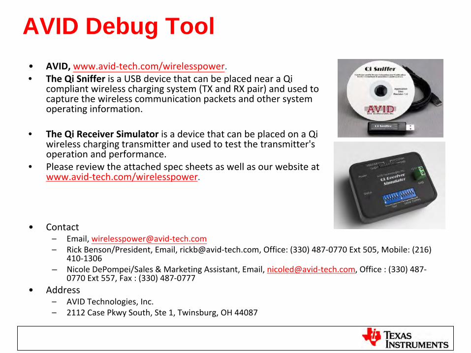
AVID Debug Tool•
AVID, www.avid‐tech.com/wirelesspower.• The Qi Sniffer
is a USB device that can be placed near a Qi
compliant wireless charging system (TX and RX pair) and used to
capture the wireless communication packets and other system
operating information.
• The Qi Receiver Simulator
is a device that can be placed on a Qi
wireless charging transmitter and used to test the transmitter's
operation and performance.
• Please review the attached spec sheets as well as our website at
www.avid‐tech.com/wirelesspower.
•
Contact–
Email, wirelesspower@avid‐tech.com–
Rick Benson/President, Email, rickb@avid‐tech.com, Office: (330) 487‐0770 Ext 505, Mobile: (216)
410‐1306
– Nicole DePompei/Sales & Marketing Assistant, Email, nicoled@avid‐tech.com, Office : (330) 487‐
0770 Ext 557, Fax : (330) 487‐0777
•
Address–
AVID Technologies, Inc.–
2112 Case Pkwy South, Ste 1, Twinsburg, OH 44087

![Coverage and connectivity issues in wireless sensor ...anrg.usc.edu/~amitabhag/papers/PMC-Feb2008.pdfWireless sensor networks (WSN) [53,52] have inspired tremendous research interest](https://img.pdfslide.us/doc/110x75/5ede2e9dad6a402d66697c7e/coverage-and-connectivity-issues-in-wireless-sensor-anrgusceduamitabhagpaperspmc-.jpg)