Embed Size (px)
DESCRIPTION
BPG_Flat_Slabs
Citation preview

Key messages1. For spans from 5 to 9 m, thin flat slabs are the preferred solution for the
construction of in-situ concrete frame buildings where a square or near-square grid is used. For spans over 9 m post-tensioning should be considered.
2. Eliminating drops results in simpler falsework and formwork arrangements,enabling rapid floor construction and giving maximum flexibility to the occupier.
3. The benefits associated with flat slab construction may well outweigh those of other structural solutions, which could be more complicated, time-consumingand ultimately more costly.
Best practice1. The benefits of using in-situ concrete flat slab construction should be investigated
at the conceptual design stage. Consider not only the benefits in terms of potentialdesign efficiencies but also the major advantages for the overall constructionprocess, notably in simplifying the installation of services and the savings inconstruction time.
2. Omit drops wherever possible. If column heads are regarded as essential, detailthem to be cast as part of the column to allow the advantages of flat soffits for thefloors to be retained.
3. Look at the construction process in its entirety, including the contractual arrangements,the procurement route, whether to use contractor detailing and the level of reinforcement rationalisation1. This is further explained in a companion Best Practice Guide, Rationalisation of flat slab reinforcement.
4. To optimise the slab thickness, consider all factors such as the method of design, thepresence or absence of holes, the importance of deflections, and previous experience.
CONSTRUCTconcrete structures group
www.bca.org.uk www.bre.co.uk www.construct.org.uk www.rcc-info.org.uk www.dti.gov.uk
BEST PRACTICE GUIDES FOR IN-SITU CONCRETE FRAME BUILDINGS ...
Flat slabs for efficientconcrete construction
Introduction
The European Concrete Building Project is a joint initiative aimed atimproving the performance of theconcrete frame industry.
The principal partners in thisambitious concrete researchprogramme are:
British Cement AssociationBuilding Research EstablishmentConstruct – the Concrete StructuresGroupReinforced Concrete CouncilDepartment of Trade and Industry
The programme involved investigatingthe process of constructing a full-sizedconcrete frame in the Large BuildingTest Facility at Cardington and testingthe performance of the completed frame.
With support from the DTI and theEngineering and Physical SciencesResearch Council, the seven-storey in-situ flat slab concrete frame wascompleted in 1998. The results of investigations into all aspects of the frame construction process are summarised in this series of Best Practice Guides.
These Guides are aimed at all thoseinvolved in the process of procurement,design and construction of in-situconcrete frames. They shouldstimulate fundamental change in this process to yield significantimprovements in the cost, deliverytime and quality of these structures.
... FROM THE EUROPEANCONCRETE BUILDING PROJECT
1
Figure 1: Reinforcing a flat slab using one-way spanning roll-out mats
This Guide outlines the benefits of using flat slab construction to improve construction efficiency
1In practical terms, reinforcement rationalisation means reducing the number of bar variations used.
2
Benefits of using flat slab constructionFaster construction
The benefits of using flat slabconstruction are becoming increasinglyrecognised. Flat slabs without drops (thickened areas of slab around thecolumns to resist punching shear) canbe built faster because formwork issimplified and minimised, and rapidturn-around can be achieved using a combination of early striking2 andflying systems. The overall speed ofconstruction will then be limited by the rate at which vertical elements canbe cast.
Reduced services and cladding costs
Flat slab construction places norestrictions on the positioning ofhorizontal services and partitions and can minimise floor-to-floor heightswhen there is no requirement for a deepfalse ceiling. This can have knock-onbenefits in terms of lower buildingheight, reduced cladding costs andprefabricated services.
Flexibility for the occupier
Flat slab construction offersconsiderable flexibility to the occupierwho can easily alter internal layouts to accommodate changes in the use of the structure. This flexibility resultsfrom the use of a square or near-squaregrid and the absence of beams,downstands or drops that complicatethe routing of services and location of partitions.
Slab thicknessHaving chosen a flat slab solution, the next key issue is to determine anappropriate slab thickness. In general,thinner slabs not only save on directmaterial costs for the frame and thesupporting foundations but also provideknock-on benefits in terms of reducedheight of the structure and lowercladding costs. Further guidance is given in Reference 1.
There is, of course, a lower limit to theslab thickness. As this is approached,the savings identified above becomeoutweighed by the extra reinforcementrequired to deal with serviceability issuesand the increased difficulty in designingand fixing it. There is also a case forproviding some margin, particularly atoutline scheme stage, to accommodatelate changes in architectural requirements
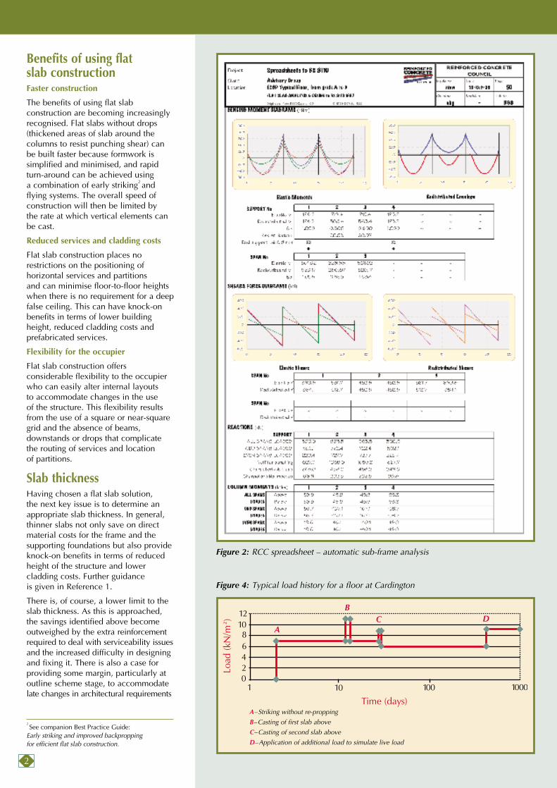
Figure 2: RCC spreadsheet – automatic sub-frame analysis
Figure 4: Typical load history for a floor at Cardington
2See companion Best Practice Guide:
Early striking and improved backpropping for efficient flat slab construction.
BC D
A
A–Striking without re-propping
B–Casting of first slab above
C–Casting of second slab above
D–Application of additional load to simulate live load

3
and the provision of holes in the slab.In addition, consideration could begiven to possible changes of use afterconstruction and to future alterations.
Choice of design methodA range of methods is available fordesigning flat slabs and analysing themin flexure at ultimate limit state. The choice should be based on:
• What is appropriate for the structure to be designed.
• What is likely to benefit the client most.
• What methods the designer is most familiar with.
For a small regular frame, the empiricalmethod using tabular moment andshear coefficients (for example thosegiven in BS 8110, Reference 2) is appropriate.
For more irregular frames, the sub-frame method in accordance with BS 8110 is likely to be the mostsuitable, although not necessarily the most economic. Computer softwarewould normally be used to apply themethod. The spreadsheets produced by the Reinforced Concrete Council(Reference 3) are one option; anexample is shown in Figure 2.
The yield-line method will enable themost economic and uniform distributionof reinforcement to be achieved. It makes the use of uniform loose bar,or one- or two-way spanning mats veryattractive, particularly for the saggingmoment reinforcement. Top steelshould be concentrated over supports to control cracking. It should be notedthat since this method considers onlypossible collapse mechanisms, a separate elastic analysis of cracking and deflection may be required.
Use of finite-element (FE) analysishas particular advantages when thefloor has irregular supports or geometry,large openings or carries concentratedheavy loads. Care is needed in modellingthe geometry, material properties andloads on the structure. A crackedsection FE analysis can also predictdeflections and crack widths.
Further information on alternativedesign methods is available in the fullerreport on which this Guide is based and in References 4 and 5.
Dealing with deflectionsFor thin flat slabs, serviceability criteriaare likely to govern the design.Deflections will generally be greatest at the centre of each panel. However,as partitions may be placed alongcolumn lines, it is usual to checkdeflections here also. The possibleeffect of deflections on cladding shouldalso be considered carefully. Edgethickenings, upstand and downstandbeams should be avoided, as theydisrupt the construction process.
In most cases a simplified approachusing span/depth ratios will be perfectlyadequate. Although BS 8110 advocateschecking the more critical direction, it is common to check column andmiddle strips in both directions,providing additional reinforcement as necessary.
Predicting deflections can be complexand will involve some form of elasticanalysis (Reference 6). When modellingthe structure using the sub-framemethod, one way of assessing mid-panel deflection is to add the averagedeflection of two parallel column stripsto the deflection of the orthogonalmiddle strip.
Finite-element (FE) analyses areparticularly useful when there isirregular geometry and large holes(see Figure 3 overleaf). They can alsodeal directly with the two-way spanningnature of the construction.
Whichever method is used to predictdeflections, appropriate modelling of cracked section properties isimportant. For example, the crackedsection inertia can be less than half the uncracked value.
Figure 3 illustrates predictions ofdeflections using an FE elastic analysiswith cracked section capabilities.
Dealing with construction loadsA typical load history for a flat slab in practice is shown in Figure 4.
A high ratio of dead to live load is an inherent feature of flat slabs (and reinforced concrete construction in general). With the trend towardsfaster construction and lower designimposed loads, the ‘spare capacity’ of a slab over its self-weight is beingreduced.
There is evidence that early striking and early loading through rapid floorconstruction has some impact on long-term deflections. This has implications
for the extent of cracking, which canmarginally increase deflection whenmore permanent loads are applied.Further guidance is given in Reference 7.
Dealing with holesHoles in flat slabs near columns needspecial attention as they reduce localresistance to both bending andpunching shear. Very small isolatedholes can be ignored (see BS 8110).The provision of additional localisedreinforcement can permit larger holeswith a dimension up to about 1/20 ofspan. Holes larger than this will requirespecific consideration in both analysisand design.
Holes away from columns are less critical.
The difficulties of providing large holesadjacent to columns can be overcomeby using structural steel shear heads asdescribed in a companion Best PracticeGuide: Prefabricated punching shearreinforcement for reinforced concreteflat slabs.
Proprietary punching shearreinforcement systemsThin flat slab construction will almostcertainly require punching shearreinforcement at columns.
This has traditionally taken the form ofa large number of individual shear linksarranged on a series of perimeters fromthe edge of the column. However,proprietary shear reinforcement systemsare now available, which can greatlyspeed up the fixing process. These aredescribed in a companion Best PracticeGuide: Prefabricated punching shearreinforcement or reinforced concreteflat slabs. The savings in labour andtime make these systems almost alwaysworthwhile.
Rationalisation of mainreinforcement Some design methods, in particularyield line, result in more rationalisedreinforcement layouts than others.
To overcome the misconception thatopting for the least material necessarilyresults in lowest overall price, thebenefits of rationalisation need to be clear to all those involved in the process.
Rationalised layouts of reinforcementalso simplify the amount of detailingand reduce the number of bendingschedules required.

4
The level of rationalisation will be a matter of engineering judgement.Elastic designs should aim to reduce thenumber of bar variations used by aboutone third compared with conventionalsolutions aimed at minimising the useof material.
If the full benefits are to be realised inpractice, rationalisation needs to bedone at an appropriate stage.Traditional contractual arrangementsare seen as a potential barrier to this.Where possible, the contractor shouldundertake the detailing asrecommended in a Construct report (see Reference 8).
Future guidanceThere remains considerable debateamongst engineers as to which designmethod to use in particularcircumstances. With the publicationof Eurocode 2 in 2003, there are plansto develop design aids and tools toassist the practising engineer in thedesign of flat slabs and other structuralconcrete components. The guidancegiven here should therefore be regardedas interim.
Best Practice Guides in this series• Improving concrete frame construction
• Concreting for improved speed and efficiency
• Early age strength assessment of concrete on site
• Improving rebar information and supply
• Early striking and improved backpropping for efficient flat slab construction
• Rationalisation of flat slab reinforcement
• Prefabricated punching shear reinforcement for reinforced concrete flat slabs
• Flat slabs for efficient concreteconstruction
These guides are available for freedownload at www.rcc-info.org.uk and projects.bre.co.uk
Research partners for this GuideBuilding Research Establishment Reinforced Concrete CouncilBritish Cement AssociationPowell Tolner & AssociatesNottingham Trent UniversityWhitby Bird and Partners
BEST PRACTICE GUIDES FOR IN-SITU CONCRETE FRAME BUILDINGS
This Best Practice Guide is based onApproaches to the design of reinforcedconcrete flat slabs by R. Moss. BRE report422. Published by Construction ResearchCommunications, London. 2001.
97.508First published 2001ISBN 0 7210 1579 4Price group A© BCA, BRE Ltd, Construct, RCC, DTI
Published by the British Cement Associationon behalf of the project partners.
British Cement AssociationCentury HouseTelford AvenueCrowthorne, Berkshire RG45 6YSwww.bca.org.uk
For further copies of the Best Practice Guidesring the Concrete Bookshop on 01344 725704.www.concretebookshop.com
All advice or information from the British CementAssociation is intended for those who will evaluate thesignificance and limitations of its contents and takeresponsibility for its use and application. No liability(including that for negligence) for any loss resulting fromsuch advice or information is accepted. Readers shouldnote that all BCA publications are subject to revision fromtime to time and should therefore ensure that they are inpossession of the latest version.
References1. GOODCHILD, C. H. Economic concrete
frame elements, Crowthorne, RCC, 1997.
Ref: 97.358.
2. BSI. Structural use of concrete. Part 1:Code of Practice for designand construction. London, BSI, 1997. BS 8110–1:1997.
3. GOODCHILD, C. H. and WEBSTER, R. M.Spreadsheets for concrete design to BS8110 and EC2. Crowthorne, RCC, 2000.Ref: 97.370. For free trial see www.rcc-info.org.uk
4. KENNEDY G. Introduction to yield linedesign. Crowthorne, RCC. To bepublished 2001. Ref: 97.385.
5. JOHNSON, D. Advanced structuralmechanics, 2
ndedition, Thomas Telford,
2000.
6. Deflections in concrete slabs and beams.Crowthorne, The Concrete Society. A joint report from BCA, The ConcreteSociety and RCC. To be published 2002.
7. CONSTRUCT. Guide to flat slab formworkand falsework. Crowthorne, The ConcreteSociety. To be published 2002.
8. CONSTRUCT. A guide to contractordetailing of reinforcement in concrete.Crowthorne, BCA, 1997. Ref: CSG/001.
Figure 3: Prediction of deflections for an irregular floor slab with large multipleopenings using finite element analysis with cracked section capabilities
Deflections


