Embed Size (px)
Citation preview
BPA Series Capacitors
Purpose, Design, Application & PerformancePresented By Mike Hulse

Series Capacitor Purpose
•Increase Transfer Capability–In lieu of constructing a new line and–At a significantly lower cost
•Improves Steady State & Transient Stability–By reducing the lines inductive reactance and–Transmission phase angle
•Reduces System Losses–By reducing sub-transmission power flow
•Improves Load Division Between Circuits–By balancing the impedance of parallel circuits
•Optimize Power Transfer–Adjusting impedance/line thermal capability relationship

Types Of Reactive Power Compensation
Series Compensation•Cost is much lower than building a new transmission circuit•Improved stability by reducing the transmission phase angle•Reduced line inductive reactance•Reduced system losses•Provides desired load division between circuits.
•Increases short circuit currents•Increases line-to-ground voltages adjacent to bank•Distance relays my trip for external faults - overreach•Can create or amplify generator sub-synchronous resonance
Source Line Load
L RL1 L2 L3
Substation
SeriesCapacitor

Types Of Reactive Power Compensation
Shunt Capacitors•Provides power factor correction •Improves power system stability with high-speed switching.•Increases the bus voltage when inserted•Act as a surge protective device for impulses
•Little impact on short circuit currents but does contribute an out rush component•Voltage can be high after load rejection
Source Line Load
LL1 L2 L3
ShuntCapacitor

Types Of Reactive Power Compensation
Shunt Reactor•Controls operating voltages by absorbing charging current from lightly loaded lines•Avoids the security and stability impacts of removing lines from service•Improves power system stability with high-speed switching.•Voltage is low after load rejection
Source Line Load
L RL1 L2 L3
Substation
ShuntReactor

Types Of Reactive Power Compensation
Static VAR Compensator (SVC)•Stabilizes bus voltage•Provides dynamic control of reactive power flow•Increases transmission capacity•Improves power system stability, power quality and damping of SSR.•Expensive but effective
Source Line Load
L RL1 L2 L3
Filte
rs
SVC

Types Of Reactive Power Compensation
Thyristor Controlled Series Capacitor (TCSC)•Provides dynamic control of reactive compensation•Improves system stability•Damps power system swings.•Reduces system loses•Controls SSR
Source Line Load
L RL1 L2 L3
Substation
TCSC
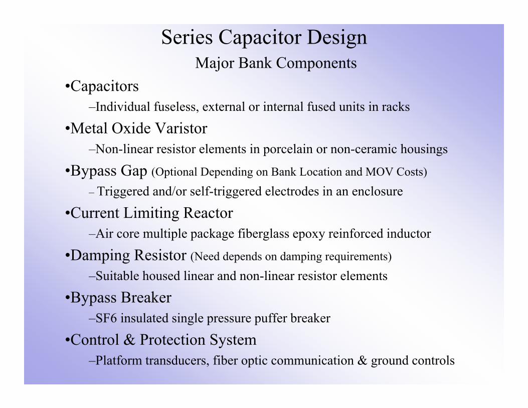
Series Capacitor DesignMajor Bank Components
•Capacitors–Individual fuseless, external or internal fused units in racks
•Metal Oxide Varistor–Non-linear resistor elements in porcelain or non-ceramic housings
•Bypass Gap (Optional Depending on Bank Location and MOV Costs)
– Triggered and/or self-triggered electrodes in an enclosure
•Current Limiting Reactor–Air core multiple package fiberglass epoxy reinforced inductor
•Damping Resistor (Need depends on damping requirements)
–Suitable housed linear and non-linear resistor elements
•Bypass Breaker–SF6 insulated single pressure puffer breaker
•Control & Protection System–Platform transducers, fiber optic communication & ground controls
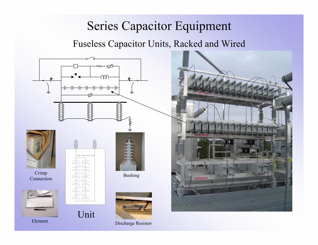
Series Capacitor EquipmentFuseless Capacitor Units, Racked and Wired
Bushing
Discharge ResistorElement
CrimpConnection
Unit

Series Capacitor EquipmentMetal Oxide Varistor

Series Capacitor EquipmentCurrent Limiting Reactor

Series Capacitor EquipmentTriggered Air Gap (TAG)

Series Capacitor Equipment• MOV monitoring, high voltage injector & TAG energy storage capacitors
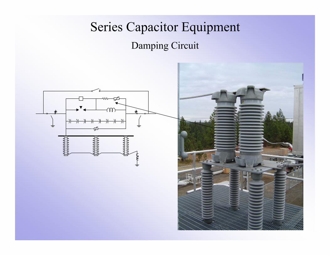
Series Capacitor EquipmentDamping Circuit

Series Capacitor EquipmentCogenel FX-12 Bypass Breaker

Series Capacitor Equipment• Platform Fiber Optic Interface & Fiber Optic Columns

Series Capacitor Equipment• Controls and Station Entrance Racks
Example screens show the events, alarms, platform quantities and waveforms
Outside to inside interface rack
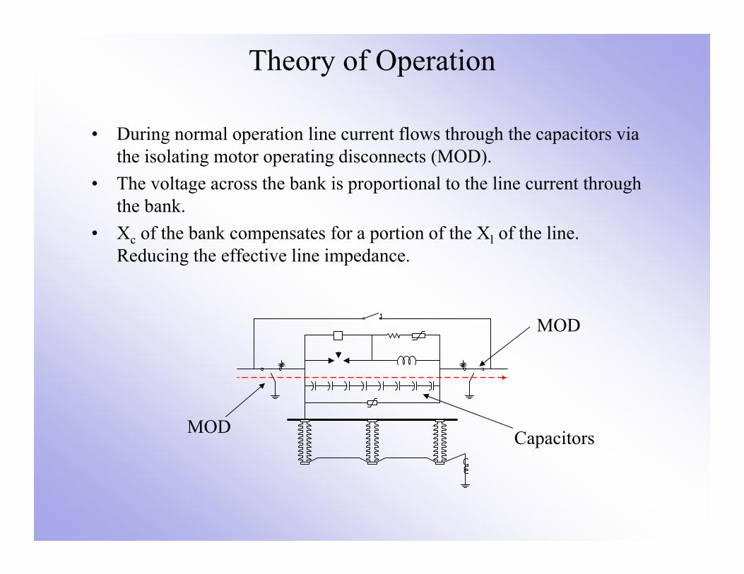
Theory of Operation
• During normal operation line current flows through the capacitors via the isolating motor operating disconnects (MOD).
• The voltage across the bank is proportional to the line current through the bank.
• Xc of the bank compensates for a portion of the Xl of the line. Reducing the effective line impedance.
CapacitorsMOD
MOD

Theory of Operation• When a fault occurs adjacent to the bank the voltage across the
capacitor increases to a point that damage would occur if the capacitor was unprotected.
• As the voltage across the metal oxide varistor (MOV) increases a portion of the bank current is transferred to the MOV controlling the voltage across the capacitor to the varistor protective level.
• For faults external to the compensated line the varistor would absorb the energy without any further protective action
Fault on the Line
Vol
tage
Current
Normal Operation
Swings & External Faults
Internal Faults
MOV Characteristic
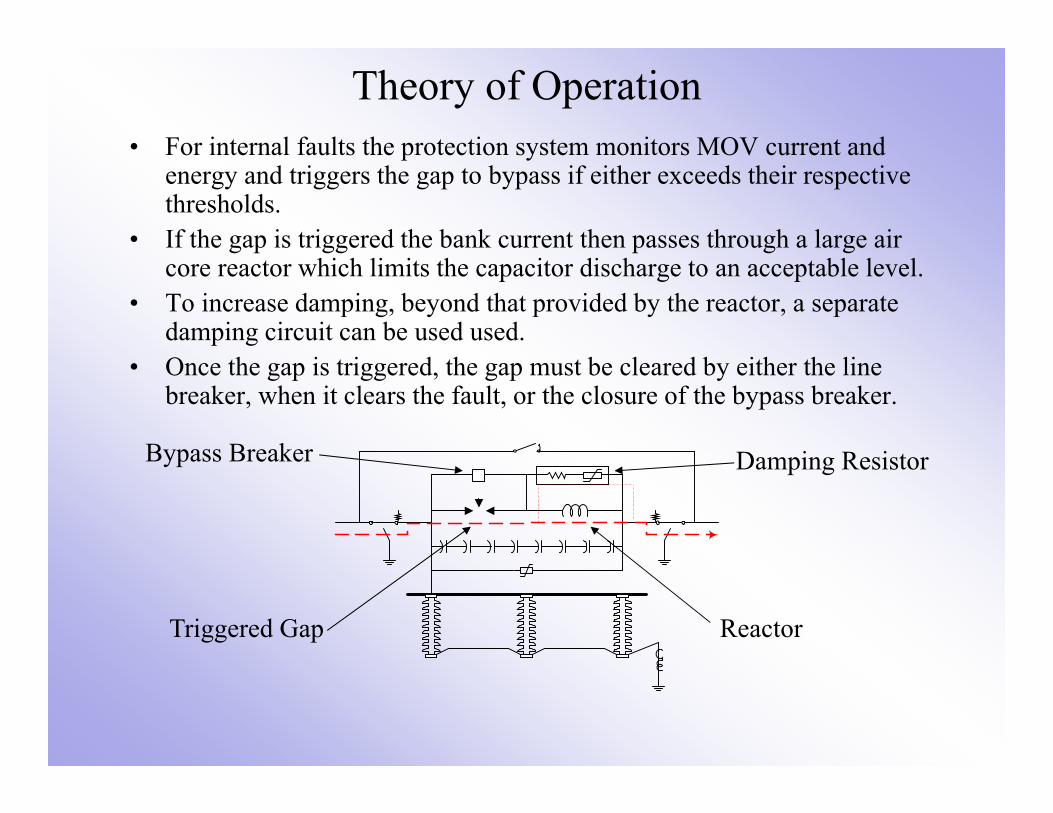
Theory of Operation• For internal faults the protection system monitors MOV current and
energy and triggers the gap to bypass if either exceeds their respective thresholds.
• If the gap is triggered the bank current then passes through a large air core reactor which limits the capacitor discharge to an acceptable level.
• To increase damping, beyond that provided by the reactor, a separate damping circuit can be used used.
• Once the gap is triggered, the gap must be cleared by either the line breaker, when it clears the fault, or the closure of the bypass breaker.
Reactor
Damping Resistor
Triggered Gap
Bypass Breaker

Theory of Operation• When the line breaker clears the fault and the gap current, the bank
resumes normal operation when the breakers reclose the line• Utilities may elect to single phase close the faulted phase bypass
breaker, to control MOV duty, and then opens the breaker after the line is high speed reclosed.
• If the gap arcing persists then the protection three phase closes and locks out the bypass breaker (right picture)

Theory of Operation• Operations can then elect to autoisolate the facility which
automatically confirms the bypass breaker is closed, closes the bypass disconnects and opens the isolating disconnects.
• Once the bank is isolated, from the power system, it can then be grounded, MOD ground blades and portable protective grounds are used, and then safely inspected
• The bank capacitors and those in the gap circuit must be individually grounded before they are physically contacted
Bypass Disconnect
Isolating Disconnect

Equipment Design
• Capacitor Bank Ratings (provided by System Planners)– Capacitive reactance in ohms (XC)
• The XC is typically 25-50% of the compensated lines positive sequence impedance.
– Continuous current rating in Amps (IC)• The ratings selected are based on a combination of the max. stable transfer
capability, the line thermal capability and current sharing between lines. System power flow and transient stability studies.
• Mvars (reactive power ratings) is calculated using the above quantities:
MVARS = 3IC2XC = 3x4000^2x19 = 912 Mvars
• 1 Per Unit (pu) voltage can also be calculated:
VC = ICXC = 4000x19 = 76 kVrms or 107.5 kVpeak
Example is based on Schultz Design

Equipment Design
• Capacitor Unit (Can) Design and Rating– The design is typically developed by the manufacturer– The type of capacitor (external fused, internal fused or fuseless) is
dependent on the voltage across the bank, the bank rated current, unit protection and to a lessor extent utility preference
– Utility specification can influence the size of the unit by specifying or limiting the:
• Enclosed Kvars (limit replacement cost for a unit failure)• Weight (per can for maintenance considerations)
– Considerations affecting a decision to use fuseless units:• Reliability improvement (without fuse related problems)• Protection improvement (element failure produces lower stress increase
compared to a fuse operation) • Lower Losses (fuse element resistance eliminated)
– At Schultz the following unit ratings were specified:• 8.44 kV, 422.2 kVARS and the unit weighed 135 lbs

Equipment Design
• Capacitor Unit Capabilities– As the figure indicates each capacitor
unit has a range of capabilities depending on the duration of the overvoltage.
– The unit design (size, weight & kvars) is directly affected by the specified 30 min rating, the 10 sec system swing current and the MOV protective level.
• Unit Design– Where the supplied data differs from the above the manufacturer
will often adjust the following to insure a survivable product:• Film thickness affecting the Volts/Mil stress• Roll voltage affecting the capacitor unit voltage rating
– These adjustments may also affect the capacitor kVAR, size, weight, and bushing voltage ratings

Equipment Design
• Metal Oxide Varistor (MOV)– The design is based on a combination utility input and the final design developed
by the manufacturer.– Typically utilities indicate:
• Bank reactance• Rated current• 30 min rating• 10 sec system swing current• Fault current (internal & external single phase and three phase faults)• Future ratings (with current and/or ohmic changes)
– The manufacturer studies provide the following MOV attributes• Estimated varistor V-I characteristics• Peak MOV current during internal & external faults via EMTP studies. • Max MOV energy requirements for external and internal fault energy.
(The bank is designed to ride through external faults where the energy and current plus margin is below the current and energy threshold. Above this level it is assumed to be an internal fault where a protective bypass can occur. The bypass can either be gap or breaker depending on the bus fault Mva and cost. The maximum internal fault energy level (after accounting for the time to bypass) is used to size the varistor.)
Equipment Design
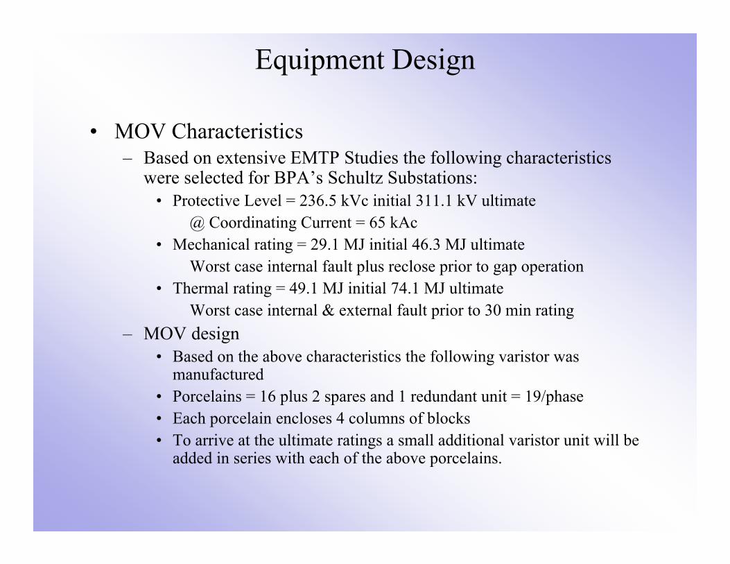
• MOV Characteristics– Based on extensive EMTP Studies the following characteristics
were selected for BPA’s Schultz Substations:• Protective Level = 236.5 kVc initial 311.1 kV ultimate
@ Coordinating Current = 65 kAc• Mechanical rating = 29.1 MJ initial 46.3 MJ ultimate
Worst case internal fault plus reclose prior to gap operation• Thermal rating = 49.1 MJ initial 74.1 MJ ultimate
Worst case internal & external fault prior to 30 min rating– MOV design
• Based on the above characteristics the following varistor was manufactured
• Porcelains = 16 plus 2 spares and 1 redundant unit = 19/phase• Each porcelain encloses 4 columns of blocks• To arrive at the ultimate ratings a small additional varistor unit will be
added in series with each of the above porcelains.

Equipment Design
• Gap System– In lieu of significantly increasing the varistor energy rating due to
the operating speed of a bypass breaker (30-40 ms) a gap (100-300 S) protection system was selected.
– The system consists of the following components:• A triggered gap• Varistor analog & pulser (VAP) system• Varistor monitoring CT’s
– The system is deenergized until (fault) current flows through the varistor and associated CT. Once current begins flowing the VAP monitors and integrates the current. Once either the energy or current protective thresholds are reached an SCR fires and initiates a process which ends with the main gap flashing over.
– The protective energy and current threshold are as follows:• Energy = 19.4 MJ initial 34.9 MJ ultimate• Current = 13.1 kAc initial 15.1 kAc ultimate

Equipment Design• Current Limiting Reactor (CLR) Design
– When either the gap fires or the bypass breaker closes the capacitors would be directly shorted. To avoid damaging the capacitors, gap or bypass breaker by currents approaching 500 kA a CLR is added to the circuit.
– The CLR’s inductive reactance in combination with the self-inductance of the bus is selected to limit the combination of peak capacitor discharge current and fault current to 140 kAc or less or within the close & latch capability of the bypass breaker. However 80 kAp capacitor only discharge was selected due to past experience. There are two procedures to calculate the required inductance:1. Conservation of energy
Energy in the capacitor E=CV2/2 Reactor E=LI2/2Solving for L yields L=CV2/I2
2. Surge Impedance Method
Solving for L yields the same equation as above– For Schultz the equations yields an inductance of:
L=139.6 F x 236.5 kV2p / 80 kA2p = 1.22 mH InitialL=104.7 F x 311.1 kV2p / 80 kA2p = 1.58 mH Ultimate
1.64 mH was purchased?
IV
CLz
Equipment Design• To avoid replacing the reactor at the time of the upgrade to 25 and
meet the 80 kAp requirement 1.64 mH was selected • Current Limiting Reactor (CLR) & Harmonics
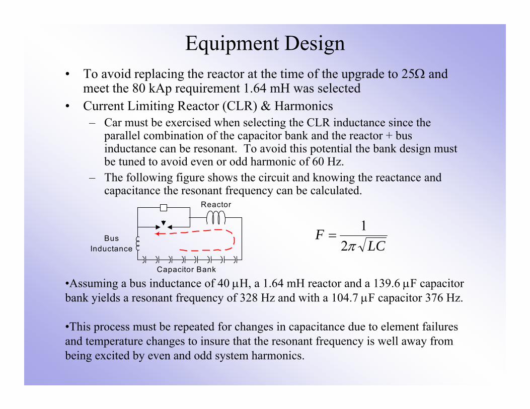
– Car must be exercised when selecting the CLR inductance since the parallel combination of the capacitor bank and the reactor + bus inductance can be resonant. To avoid this potential the bank design must be tuned to avoid even or odd harmonic of 60 Hz.
– The following figure shows the circuit and knowing the reactance and capacitance the resonant frequency can be calculated.
LCF
21
BusInductance
Reactor
Capacitor Bank
•Assuming a bus inductance of 40 H, a 1.64 mH reactor and a 139.6 F capacitor bank yields a resonant frequency of 328 Hz and with a 104.7 F capacitor 376 Hz.
•This process must be repeated for changes in capacitance due to element failures and temperature changes to insure that the resonant frequency is well away from being excited by even and odd system harmonics.

Equipment Design
• Damping Circuit– At the time the gap fires or the bypass breaker closes, the energy
stored in the capacitors is transferred to the magnetic field of the reactor. This transfer back and forth would continue forever in a lossless environment.
– Without damping (resistance around the L-C loop) the capacitor would be overstressed and fail.
– The following illustrates (using ATP) the impact of changing the damping resistance by a factor of ten

Equipment Design
• Damping Circuit Options– Reactor Modifications
• Use of de-qing rings (Stainless steel ring immediately above the air core reactor.) The rings introduce eddy current losses due to the reactor’s magnetic field.
• Modification of the winding arrangement and materials can also increase losses.
– After careful study it was determined to leave the reactor as is. This was due to the:
• Extreme force applied to the de-quing ring during gap operations & faults • Impact on the winding temperature rise.
– Instead a parallel damping circuit was developed.– The circuit consists of linear and non-linear resistors in a porcelain
housing– The damping circuit was located immediately parallel to the CLR.

Equipment Design• Damping Circuit Design
– Sounds simple just add a resistor in parallel with the CLR. Not so due to additional energy that would be absorbed from 60 hZ fault current flowing through the reactor. Two options were available to address this issue:
• Install a gap in series with the linear resistor • Install non-linear resistors in series with the linear resistors
– The linear & non-linear resistor design was selected and was developed to meet the following requirements:
• The ratio of the voltage magnitude is less than 0.90 from one half cycle to the next of the same polarity.
• The I2t will be within the capability of the capacitor.• To minimize losses non-linear resistors will be added in series with the linear
resistor.• The non-linear resistor is sized to eliminate an significant duty to the resistor
element during faults while the bypass breaker is closed.– Computer simulations were conducted to verify the I2t, and identify the
division of energy between the linear and non-linear elements when compared to their capabilities under multiple contingencies.

Equipment Design
• Bypass Breaker– A standard breaker is utilized except for the following:
• The breaker is close priority (close on low pressure and other problems)• Once closed & locked-out the breaker is latched (will not drift open)• The interrupter rating is based on the bank:
– Continuous operating voltage (I*XC)– Varistor protective level (BIL)– Continuous current and 30-min current rating (I)– Capacitor discharge plus fault current (Close and latch)
• The line to ground capability is based on the system voltage– At 500 kV this is typically 1550 or 1800 kV BIL
– The breaker is the primary protective device for the gap system and bypasses the for other problems such as platform faults. The close time for the breaker is as fast as two cycles.
– The breaker may be operated either locally of remotely to bypass or insert the bank.