Embed Size (px)
Citation preview

S E L E C T I O N G U I D E
TelecomCircuit Protection
Circuit Protection Solutions

The Bourns MissionOur goal is to satisfy customers on a global basis while achieving sound growth with technological products of innovative design, superior quality and exceptional value. We commit ourselves to excellence, to the continuous improvement of our people, technologies, systems, products and services, to industry leadership and tothe highest level of integrity.

Introduction . . . . . . . . . . . . . . . . . . . . . . . . . . . . . . . . . . . . . . . . . . . . . . . . . . . . . . . . . . . . . . . . . . . . . . . . . . . . . . .2
Applications - What Protection do you Need?What is a Surge? . . . . . . . . . . . . . . . . . . . . . . . . . . . . . . . . . . . . . . . . . . . . . . . . . . . . . . . . . . . . . . . . . . . . . . . .3
What is Protection? . . . . . . . . . . . . . . . . . . . . . . . . . . . . . . . . . . . . . . . . . . . . . . . . . . . . . . . . . . . . . . . . . . . . .3
Lightning - Global and Different . . . . . . . . . . . . . . . . . . . . . . . . . . . . . . . . . . . . . . . . . . . . . . . . . . . . . . . . . .4
Where will the System be Used? . . . . . . . . . . . . . . . . . . . . . . . . . . . . . . . . . . . . . . . . . . . . . . . . . . . . . . . . . . .5
Coordination is No Longer Optional . . . . . . . . . . . . . . . . . . . . . . . . . . . . . . . . . . . . . . . . . . . . . . . . . . . . . . .6
Standards . . . . . . . . . . . . . . . . . . . . . . . . . . . . . . . . . . . . . . . . . . . . . . . . . . . . . . . . . . . . . . . . . . . . . . . . . . . . .6
System Technology . . . . . . . . . . . . . . . . . . . . . . . . . . . . . . . . . . . . . . . . . . . . . . . . . . . . . . . . . . . . . . . . . . . . .8
Location . . . . . . . . . . . . . . . . . . . . . . . . . . . . . . . . . . . . . . . . . . . . . . . . . . . . . . . . . . . . . . . . . . . . . . . . . . . . . .8
Application - Central Office (CO) and Access . . . . . . . . . . . . . . . . . . . . . . . . . . . . . . . . . . . . . . . . . . . . . . . .9
Application - Customer Premise Equipment (CPE) . . . . . . . . . . . . . . . . . . . . . . . . . . . . . . . . . . . . . . . . . . .12
Digital Technology . . . . . . . . . . . . . . . . . . . . . . . . . . . . . . . . . . . . . . . . . . . . . . . . . . . . . . . . . . . . . . . . . . . . .14
Useful Sources . . . . . . . . . . . . . . . . . . . . . . . . . . . . . . . . . . . . . . . . . . . . . . . . . . . . . . . . . . . . . . . . . . . . . . . .15
Network Diagram . . . . . . . . . . . . . . . . . . . . . . . . . . . . . . . . . . . . . . . . . . . . . . . . . . . . . . . . . . . . . . . . . . . . .16 & 17
Technology - Which Protection Technology is Right for the Equipment?The Basics - Overvoltage and Overcurrent . . . . . . . . . . . . . . . . . . . . . . . . . . . . . . . . . . . . . . . . . . . . . . . . . .18
What Happens After a Surge or if the Device Fails? . . . . . . . . . . . . . . . . . . . . . . . . . . . . . . . . . . . . . . . . . . .18
Speed and Accuracy are Major Factors in Determining Equipment Stress Levels . . . . . . . . . . . . . . . . . . . .19
Technology Selection - Overvoltage Protectors . . . . . . . . . . . . . . . . . . . . . . . . . . . . . . . . . . . . . . . . . . . . . .21
Gas Discharge Tubes (GDTs) . . . . . . . . . . . . . . . . . . . . . . . . . . . . . . . . . . . . . . . . . . . . . . . . . . . . . . .22
Thyristor-Based Devices . . . . . . . . . . . . . . . . . . . . . . . . . . . . . . . . . . . . . . . . . . . . . . . . . . . . . . . . . . .24
Metal Oxide Varistors (MOVs) . . . . . . . . . . . . . . . . . . . . . . . . . . . . . . . . . . . . . . . . . . . . . . . . . . . . . .24
Transient Voltage Suppressors (TVSs) . . . . . . . . . . . . . . . . . . . . . . . . . . . . . . . . . . . . . . . . . . . . . . . .25
Technology Selection - Overcurrent Protectors . . . . . . . . . . . . . . . . . . . . . . . . . . . . . . . . . . . . . . . . . . . . . .25
Positive Temperature Coefficient (PTC) Thermistors . . . . . . . . . . . . . . . . . . . . . . . . . . . . . . . . . . . .26
Fuses . . . . . . . . . . . . . . . . . . . . . . . . . . . . . . . . . . . . . . . . . . . . . . . . . . . . . . . . . . . . . . . . . . . . . . . . . .27
Heat Coils . . . . . . . . . . . . . . . . . . . . . . . . . . . . . . . . . . . . . . . . . . . . . . . . . . . . . . . . . . . . . . . . . . . . . .27
Line Feed Resistors . . . . . . . . . . . . . . . . . . . . . . . . . . . . . . . . . . . . . . . . . . . . . . . . . . . . . . . . . . . . . . .27
Thermal Switches . . . . . . . . . . . . . . . . . . . . . . . . . . . . . . . . . . . . . . . . . . . . . . . . . . . . . . . . . . . . . . . .28
Modes of Overvoltage Protection . . . . . . . . . . . . . . . . . . . . . . . . . . . . . . . . . . . . . . . . . . . . . . . . . . . . . . . . .28
Technology Selection - Integrated Solutions . . . . . . . . . . . . . . . . . . . . . . . . . . . . . . . . . . . . . . . . . . . . . . . . .29
Multi-Stage Protectors . . . . . . . . . . . . . . . . . . . . . . . . . . . . . . . . . . . . . . . . . . . . . . . . . . . . . . . . . . . .29
Integrated Line Protection Modules . . . . . . . . . . . . . . . . . . . . . . . . . . . . . . . . . . . . . . . . . . . . . . . . . .30
Product Selection GuidesGas Discharge Tubes . . . . . . . . . . . . . . . . . . . . . . . . . . . . . . . . . . . . . . . . . . . . . . . . . . . . . . . . . . . . . . . . . . .32
Multifuse® PPTC Resettable Fuses . . . . . . . . . . . . . . . . . . . . . . . . . . . . . . . . . . . . . . . . . . . . . . . . . . . . . . . . .34
TISP® Thyristor Surge Protectors . . . . . . . . . . . . . . . . . . . . . . . . . . . . . . . . . . . . . . . . . . . . . . . . . . . . . . . . .35
Surge Line Protection Modules . . . . . . . . . . . . . . . . . . . . . . . . . . . . . . . . . . . . . . . . . . . . . . . . . . . . . . . . . . .41
Telefuse™ Telecom Fuses . . . . . . . . . . . . . . . . . . . . . . . . . . . . . . . . . . . . . . . . . . . . . . . . . . . . . . . . . . . . . . . . .43
Index
1

2
Bourns is pleased to present this comprehensive
guide to Telecom Circuit Protection, encompassing
our broad range of technologies and products. This
guide will provide the background information and
selection recommendations needed to ensure that
your next project achieves the level of cost-effective
field reliability demanded by today’s customers.
Bourns commissioned a survey of Telecom Circuit
Protection users worldwide to determine their prior-
ities and needs. We found that reliability, technical
and design support, and exemplary knowledge of
protection technology were by far the three most
cited items. Bourns is committed to meeting each of
these three requirements:
Reliability – Reliability requires an understanding of
the capabilities and specifications of circuit protection
technology. Bourns has a global reputation for quality
products, and our circuit protection devices have
consistently demonstrated reliability in field applica-
tions. Bourns is committed to the complete support
of a circuit protection solution for the life of a
program.
IntroductionTechnical and Design Support – Bourns’ team of
specialized Sales and Field Application Engineers are
ready to bring additional in-depth expertise to your
next project. Through our interactive website and
customer service locations, Bourns is always available
to answer circuit protection design questions and
provide valuable assistance and support.
Knowledge of Protection Technology – Bourns
boasts the industry’s widest range of Telecom over-
voltage and overcurrent protectors. Our active
involvement in international protection standards
organizations ensures world-class technology and
applications expertise.
Bourns continues to develop an innovative range of
integrated circuit protection products using our
knowledge and expertise to combine multiple
technologies into optimized single devices designed
to save both cost and board space. Whether you need
a single product or a complete protection solution,
Bourns Telecom Circuit Protection team is there to
help you. We look forward to working with you.

Communication systems are vulnerable to electrical
damage from lightning or other surges. As systems
become more complex, they also become more
vulnerable. Balancing the cost, standards compliance
and field reliability of protection is both a commercial
and technical challenge, compounded by the addi-
tional performance constraints of modern digital
networks such as xDSL.
This section is intended to outline those challenges,
illustrate the fundamentals of protection and identify
those international standards relevant to specific
applications. The next section will examine individual
protection technologies and their selection.
Bourns engineers have helped designers with major
projects in every region of the world, successfully
protecting hundreds of millions of telephone circuits.
Our uniquely broad range of protection solutions
enables us to identify the most suitable technology
for each application. Whether the goal is to achieve
standards compliance or tackle a specific field prob-
lem, Bourns’ experience and product offering are the
solution to a myriad of design requirements.
are significant for device survival and safety. Direct
contact to the AC (power cross) causes high currents,
while lower currents result from power induction.
Obviously, a single device protection solution is
seldom possible.
Applications - What Protection is Needed?
Lightning kA, kV µs Negligible
Power Cross 60 A <30 mins Significant
Power Induction
7 A <30 mins Crucial
BulkAmplitude DurationHeating
Table 1. Different surge sources result in very different effects
Reliability TipEffective protection usually requires overcurrent and
overvoltage devices.
Reliability TipComplying with standards does not guarantee
field reliability.
Figure 1. Protecting “Quality of Service” requiresmore than standards compliance
What is a Surge?A “surge” is a short-term increase in voltage or
current. Both lightning and the AC power distribution
system cause surges, but of very different magnitudes
and durations (see Table 1). These events can either
be via direct contact or by field or resistive coupling
from events close to the telephone system, resulting
in a wide variety of threats. For example, the effects
of a power line fault caused by lightning may even be
more threatening to the telephone system than the
original lightning.
The dangers of large voltages and currents are obvious,
but time is also important. Lightning is too fast for
bulk heating to be critical, whereas for the longer
term currents of AC power faults, heating effects
What is Protection?Protection performs several key functions as outlined
in Figure 1: first it must prevent or minimize damage
caused by a surge; then it must ensure that the system
returns to a working condition with minimal disrup-
tion to service. It is vital that under normal conditions
the protection does not interfere with the signal,
creating special challenges for xDSL and other digital
technologies. The protection must also fail in a safe
manner during overstress.
3
Qualityof service
Field reliability
Standardscompliance
Signalintegrity

4
boundary of the premises. It is designed to redirect
the bulk of the surge energy away from personnel
and equipment by passing significant current to
ground. Secondary protection (Figure 3) is optimized
to protect the most sensitive parts of the equipment
from any residual voltage surges let through by the
Primary protector. Some telecommunications ICs
have very precisely defined time-dependent Safe
Operating Areas, requiring precise and predictable
behavior as illustrated in Figure 4. There is typically
some resistance added between the Primary and
Secondary protection, either as part of the system
requirements or the protection regime.
Within each of the core protection types listed in
Table 2, there are several individual technologies.
These will be reviewed in more detail in the
Technology section. Each technology has different
strengths and weaknesses, and only by understanding
their relative merits can protection be optimized for
a given installation. A quick review of Table 3
demonstrates that no single ideal solution exists for
all locations within the telephone network so cascaded
protection is often employed.
Overcurrent Limit peak currentSeries (or parallelfor primary)
Overvoltage Limit peak voltage Parallel
Overcurrent Coordinate voltage and and current CombinationOvervoltage protection
Protection Type
Action Connection
Table 2. Protection falls into three basic types
GDT Fair Poor Very high
Thyristor Fair Good High
MOV Fast Poor High
TVS Very fast Good Very low
CurrentSpeed AccuracyRating
Overvoltage
Polymer PTCSlow Good Low
Thermistor
Ceramic PTCSlow Good Low
Thermistor
Fuse Very slow FairMedium/
High
Heat Coil Very slow Poor Low
Thermal Switch Very slow Poor High
CurrentSpeed AccuracyRating
Overcurrent
Table 3. Summary of technology characteristics
Figure 2. Typical format for Primary protection
Overcurrentprotector
Overvoltageprotector
Primary Protection
Prot
ecte
dsid
e
Unpr
otec
ted
side
Figure 3. Typical format for Secondary protection
Overcurrentprotector
Overvoltageprotector
Secondary ProtectionPr
otec
ted
side
Unpr
otec
ted
side
Lightning - Global and DifferentWeather does not understand national boundaries,
and varies with geography as shown in Figure 5.
Partly for this reason, local standards have evolved to
describe a lightning strike, usually containing major
similarities, and critical differences. However, meeting
each local standard is only the start of protection
Primary protection (Figure 2) diverts most of the
surge energy away from the more sensitive/important
areas of the system and is typically located at the

5
design. It requires a
deeper understanding of
protection to achieve the
competitive advantage of
reliable operation under
field conditions.
Where will the Systembe Used?Surge levels depend on
both the original source
energy and how it is dis-
tributed. Line density
varies considerably in
Central Office or Access
Equipment within urban
and rural areas. At higher
densities, individual line surges tend to be smaller as
energy is spread over multiple pair counts. In loop
applications pair counts tend to be lower, and in fiber
rich environments, these loops are becoming shorter
in length. Both trends tend to increase the surge energy
distributed over individual lines.
For example, high exposure lines (remote terminals
and less than 1,000 ft/300 m line length) with severe
lightning surges are required under GR-974 and
GR-1361 to have protection requirements of a current
carrying capability of 2000 A 10/250. Within areas of
similar flash density, factors such as ground resistivity
(ρ), as well as the type of environment and equipment
can have a direct impact on the resultant surge
Figure 5. Lightning is global, but not uniform, as data
from space emphasizes
0
5
10
15
-120
-110
-100
-90
-80
-70
-60
-50
PBL 3762A SLIC Ring and Tip Voltage Withstand vs TimeVo
ltag
es (w
ith
V BAT
set t
o –5
0 V)
– V 0.25 µs
1 µs
10 ms
Time
VBAT
VBAT - 40 V
VBAT -20 V
DC and 10 ms pulse rating increasedto -70 V (independent of VBAT value)by use of series battery feed diode
VBAT -70 V
10 ms
1 µs
0.25 µs
Figure 4. Telecom ICs have precisely defined
Safe Operating Areas, requiring precise protection
Figure 6. Location influences stress levels within telecommunications equipment
Grou
nd Po
tent
ial R
ise
Ground Resistance
High Flash
Densit
y
Low Flash Density
Equi
pmen
t Stre
ss Le
vel
Number of Lines
Custo
mer
Pre
mise
Acce
ss
Cent
ral O
ffice
Line S
tress
Leve
l
Number of Lines
RuralStress
SuburbanStress
UrbanStress
Further InformationSee thunder.nsstc.nasa.gov
for the latest publishedlightning plot.

6
Safety TipEquipment deployed in customer premises, and
accessible to untrained personnel, has additional safety requirements.
amplitude, as illustrated in Figure 6. Therefore,
depending on where it is deployed, each protection
scheme will have different field reliability. For global
deployment, once standards are met, engineers
should understand potential field stress levels in
order to predict levels of field reliability. For example,
ITU-T K.44 Figure I.1-8/K.44 shows field AC induc-
tion surge levels measuring between 2 A, 3 s and 8 A,
0.2 s, implying that the sensitivity and dissipation of
current protection can have a significant impact on
maintenance issues.
Coordination is No Longer OptionalConsider the generic protection scheme of Figure 7.
P1 is the primary protection, R is a coordination and
current limit resistor and P2 is the secondary protec-
tion. Coordination will not occur if the secondary
protection limiting voltage of R and P2 is lower than
the sparkover voltage of P1 at the expected sparkover
instant (see Figure 8). Both P1 and P2 may be
acceptable for individual
purposes, but com-
bined the interaction
defeats the overall
protection strategy.
The potential for
interaction is present
wherever more than
one protector is on the
same line. The action
of each device, whether
within a single equip-
ment or between
equipments must be
Standards TipCoordination of primary and secondary protection is
now mandatory for ITU-T equipment compliance.
Figure 7. Coordination of
protection is now mandatory
for ITU-T compliance
Coordination Resistance
PrimaryProtection
SecondaryProtection
Coordinationof Protection
Unpr
otec
ted
Side
Equi
pmen
t Ele
ctro
nics
R
P1
P2Coordination
Figure 8. With different time-current characteristics,
primary/secondary coordination is crucial
StandardsThere are numerous regional and national standards,
and even focusing on ITU-T and USA standards can
be confusing. The Location section highlights where
key standards are applicable within specific applica-
tions. As the standards change frequently, Bourns
recommends obtaining the latest versions of the
relevant documents. For example, the ITU-T recently
introduced the concept of two-level “Basic” and
“Enhanced” requirements within a single standard.
For the future, work is underway at the World Trade
LimitingVoltage
atSparkover
InstantV
Uncoordinated
Impulse• low current• slow rise time• long duration
• high current• fast rise time• short duration
R + P2
P1
Coordinated
Reliability TipLow flash density and high soil resistivity can producemore stress than high flash density and low resistivity.
coordinated. From the year 2000 forward, coordina-
tion of protection has been mandatory as part of
ITU-T K.20, K.21, and K.45. Designing a coordinated
protection scheme is no longer just good practice; it
is a prerequisite to international compliance.
Practical guidelines for protection coordination are
presented in the Technology section.

7
Organization to consider unifying these multiple
requirements into a single standard.
Since real world surges are unpredictable, even when
standards are mandatory, compliance does not
guarantee reliability. Satellite observation has
enabled global counting of lightning flashes and
work is underway to investigate the multiple strikes
typically present in each flash. Since real world
multiple surges are currently not modeled in the
standards, they represent another area where field
reliability is not assured. It is likely that standards will
be extended to include such multiple surge tests.
Reliability TipComplying with standards does not guarantee
field reliability.
Harsh operating conditions, high access or repair
costs and demands for superior quality of service
may all justify additional protection beyond the
minimum levels within the standards. To illustrate
the interaction of standards and protection design
shown in Figure 9,
TIA/EIA-IS-968 (FCC
Part 68) specifies two
levels of surge, Type A
and Type B. Telecom-
munications equipment
must survive and be
operational after Type
B surges, but is allowed
to be non-operational
after Type A surges.
Figure 9. Compliance, technical and commercial
requirements must influence protection design
Further InformationMany standards include valuable application guidance.
Application
CompareSolutions
Standards Requirements
Equipment
Standards TipIn addition to international standards, it is
always important to check the local requirements for target markets.
POTS 56 k 270 V 600 Non-critical Non-critical
Pair Gain 160 k 145 V DC 150 Low Low
ISDN 128/144 k 120 V DC 150 Low Low
T1 / E1 1.5 - 2 M 150 V DC 120 Very low Low
xDSL 2-50 M Various <100 Very low Very low
HDSL 1.5M 190 V DC <100 Very low Very low
BandwidthSystem
ImpedanceCapacitance
Protection(bps)
Voltage(Ω)
of ShuntResistance(Maximum) Element
Table 4. System technology places different limitations on protection
This means that a system needing maintenance
before returning to service, perhaps by replacing a
fuse, could still be compliant. Upgraded protection,
or careful coordination of protectors and current
limiting devices could permit passing a Type A surge
with an automatic return to service. This scenario
may yield a higher component, but a lower lifetime
cost.

8
System TechnologyThe level of protection required and its justification
depends on what is being protected. Table 4 and the
following sections emphasize each system technology
and the particular requirements and constraints
placed on protection design.
The dynamics of a
world market have a
significant impact on
protection design. For
example, as Central
Office copper lines
transfer to access
equipment, protection
must be increasingly
self-resetting and more
effective at reducing
expensive repair call-
outs. Although line
density is increasing
in urban areas and
reducing stress levels,
installations are reach-
ing more remote areas
where surge threats
increase substantially
due to a lack of
“shielding” from taller
structures.
Digital services are also
making new demands
Reliability TipProtection must be matched to the value and vulnerability of the equipment, as well as the
down time and repair cost.
on protection, both to permit increased bandwidth
and to provide more precise protection of increas-
ingly sophisticated and vulnerable line-card
components. Recently, Telcordia issued a revision of
GR-974 that addresses Next Generation Broadband
Protectors. Bourns engineers worked with Telcordia
on the development of this technology neutral
specification.
LocationProtection requirements vary depending upon where
the equipment is deployed (see Figure 10 and Tables
5 and 6). The Central Office (CO) or exchange and
Customer Premises Equipment (CPE) are easily
identified. Access is essentially everything else and
typically covers intermediate network facilities such
as those used to consolidate POTS lines onto fiber or
coax. Although ITU-T applies different standards to
each, from a protection point of view, CO and Access
Primary K.28 X X X
Secondary
K.20 X
K.21 X
K.44 X X X
K.45 X
Safety IEC 60950 X
Notes:K.44 describes the circuits to be used for testing.
K.36 provides useful guidelines for the selection of protective devices.
Figure 10. Location determines which standards are applicable
NetworkInterface
Device(NID) NID
Line cards
Equipment Rack
Customer Premise(Subscriber)
Customer Premise(Subscriber)
Access Central Office(Telecom Center)
OutsidePlant
Access = Any equipment between the subscriber and the Telecom Center
ITE
MDFMDF
ITE
International CustomerCustomer
AccessCO
CONID MDF
Table 5. Specific International standards for location within the system
Standards TipSome standards offer multiple levels of compliance.
Designers must identify the right level for their target market.

9
are very similar. CPE standards, however, reflect the
different technical and safety issues of an end user
site.
Figure 11. Thyristor protectors provide the precision to protect SLICs
Application - Central Office (CO) and AccessIn addition to device technology, demand for
increased density on line cards also requires attention
to packaging. Surface mount packages and those
containing multiple devices, including multi-chip
modules with multiple technologies improve line
density.
Connected directly to the telephone line, integrated
circuits such as SLICs and LCASs are perhaps the
most vulnerable on the
network. These are
specialized components
requiring precise pro-
tection normally
provided by thyristor-
based protectors.
Working with several
major suppliers of
these circuits, Bourns
developed a broad
range of protectors
designed to maximize
protection for specific
models of line card
ICs, as illustrated in
Figure 11.
Recent changes to
ITU-T equipment
standards made
protection coordination
mandatory. Documenta-
tion increased by over
one hundred pages,
emphasizing the need
for timely review of
new requirements. As
well as monitoring
changes, Bourns is an
active contributor to the
standards process.
Standards TipBe sure to identify the right standards for your type
of equipment, and for your planned regions of deployment.
Table 6. Specific USA standards for location within the system
GR-974 X X X
Primary GR-1361 X X X
RUS PE-80 X X X
SecondaryTIA/EIA-IS-968
X(FCC Part 68)
GR-1089 X X X
Safety UL 60950 X
USA CustomerCustomer
AccessCO
CONID MDF
PBL 3xxx SLIC Voltage Withstand and TISPPBLx Voltage Limiting vs Time
Volt
age
– V 0
10
20
30
40
VBATM
VBATM -10VBATM -20VBATM -30VBATM -40VBATM -50VBATM -60VBATM -70
PBL 386 20/1PBL 3762APBL 3796
TISPPBLx
TISPPBLx
Time10 ms
1 ms10 µs
1 µs0.25 µs
PBL 386 20/1
PBL 3796
PBL 3762A

10
CO and Access - Key Relevant Standards
Primary protection
ITU-T K.28 (Thyristor)ITU-T K.12 (GDT)
IEC 61643-311 (GDT)
GR-974(Solid State &
Hybrid)GR-1361 (GDT)
RUS PE-80 (GDT)
Secondary protection
ITU-T K.20 (CO)ITU-T K.45 (Access)
ITU-T K.44IEC 61643-21
GR-1089
International USA
ESD protection
IEC 61000-4-2 IEC 61000-4-2
Component standards
ITU-T K.12 (GDT)IEC 61643-311 (GDT)IEC 61643-321 (TVS)
IEC 61643-341(Thyristor)
IEEE Std C62.31(GDT)
IEEE Std C62.32(Carbon Block)IEEE Std C62.33
(MOV)IEEE Std C62.35
(TVS)IEEE Std C62.37
(Thyristor)
ITU-T K.12, K.20, K.44 New/revised& K.45 in 2000
K.44 Revisionanticipated
TELCORDIA GR-974, GR-1089 Revised for 2002
EN/IEC 61643-311-321, New for 2001341, -21
EN/IEC MOV, Modules Anticipated2002-2004
IEEE C62.31 (GDT), C62.32 In revision for(Carbon Block), 2003
C62.37 (Thyristor) Reaffirmed in2002
ACTA TIA/EIA-IS-968 New for 2001,Replaces FCCPart 68
Organization Standard Comment
CO and Access - Recent / Future Standards
CO and Access - Suitable Protection Technologies
GDT Y H
Thyristor Y YVoltage
MOV HProtection
TVS H
PTC Thermistor Y Y
Fuse Y
Thermal Switch Y Current
Heat Coil A Protection
Line Protection YModule
Primary Secondary
Y = SuitableH = Suitable as part of GDT hybridA = Suitable except for ADSL and higher data rates
Data Sheet TipCheck for space-saving multiple device, or
multiple technology components as well as surface mount packaging.
Standards TipStandards are updated, often with significant impact.Monitor current and future changes to confirm that
your design remains compliant.

11
TESTRELAY
RINGRELAY
SLICRELAY
TESTEQUIP-MENT
RINGGENERATOR
S1a
S1b
Th1
Th2
Th3
Th4
Th5
SLICSLIC
PROTECTORRING/TEST
PROTECTION
S2a
S2b
TISP3xxxF3
or7xxxF3
S3a
S3b
VBATH
TISP61089B
C1220 nF
RING
TIP
4B06B-524-400or
4B06B-522-500
2026-xxor
2036-xx
Linecard Protection with Electromechanical Relays
CO and Access - Relevant Sub-assemblies
Surge
C2100 nF
IG
SLIC 2
TISP6NTP2A
C1100 nF
SLIC 1
SLICPROTECTOR
0 V
0 V
VBAT2
VBAT1
4A12P-516-500
Integrated Line Protection for Multiple SLICs
Surge
12
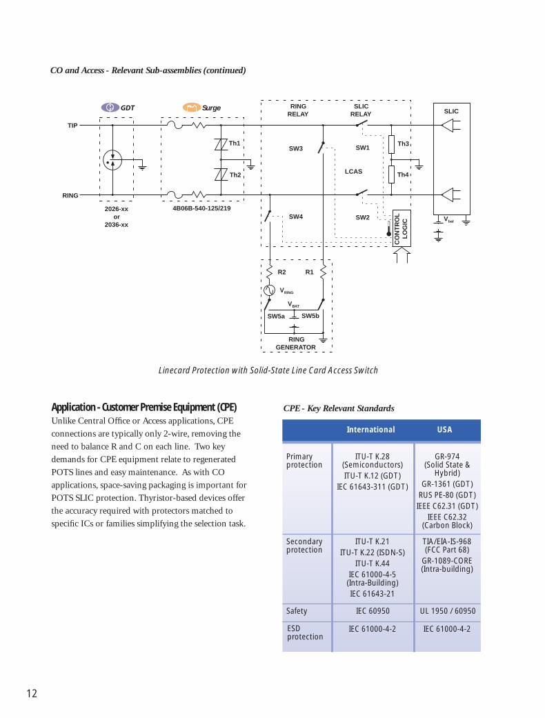
Application - Customer Premise Equipment (CPE)Unlike Central Office or Access applications, CPE
connections are typically only 2-wire, removing the
need to balance R and C on each line. Two key
demands for CPE equipment relate to regenerated
POTS lines and easy maintenance. As with CO
applications, space-saving packaging is important for
POTS SLIC protection. Thyristor-based devices offer
the accuracy required with protectors matched to
specific ICs or families simplifying the selection task.
Primary protection
ITU-T K.28(Semiconductors)ITU-T K.12 (GDT)
IEC 61643-311 (GDT)
GR-974(Solid State &
Hybrid)GR-1361 (GDT)
RUS PE-80 (GDT)IEEE C62.31 (GDT)
IEEE C62.32(Carbon Block)
Secondary protection
ITU-T K.21ITU-T K.22 (ISDN-S)
ITU-T K.44IEC 61000-4-5
(Intra-Building)IEC 61643-21
TIA/EIA-IS-968(FCC Part 68)
GR-1089-CORE(Intra-building)
International USA
ESD protection
IEC 61000-4-2 IEC 61000-4-2
Safety IEC 60950 UL 1950 / 60950
CPE - Key Relevant Standards
RINGRELAY
SLICRELAY
RINGGENERATOR
SW5bSW5a
R1R2
VBAT
VRING
Th1
Th2
Th3
Th4
SLIC
Vbat
RING
TIP
SW3
SW4
SW1
SW2
CO
NT
RO
LL
OG
IC
LCAS
4B06B-540-125/2192026-xxor
2036-xx
Linecard Protection with Solid-State Line Card Access Switch
Surge
CO and Access - Relevant Sub-assemblies (continued)

13
CPE - Suitable Protection Technologies
GDT Y H, L
Thyristor U YVoltage
MOV H YProtection
TVS H Y
PTC Thermistor Y Y
Fuse Y Current
Thermal Switch Y Protection
Heat Coil A
Primary Secondary
Y = SuitableA = Suitable except for ADSL and higher data ratesH = Suitable as part of hybridL = Suitable for LAN or ADSL useU = Suitable for urban high density deployment only
Basic ADSL Interface
CPE - Recent / Future Standards
As with CO and Access, the ITU-T standards have
recently expanded significantly.
ITU-T K.12, K.44 & K.21 New/Revisedin 2000
K.44 Revisionanticipated
TELCORDIA GR-974, GR-1089 Revised for2002
EN/IEC 61643-311, -321, New for 2001-341, -21
EN/IEC MOV, Modules Anticipated2002-2004
FCC TIA/EIA-IS-968 In revision for(FCC Part 68) 2002
IEEE C62.31, C62.32 In revision for2003
C62.37 Reaffirmed in2002
ACTA TIA/EIA-IS-968 New for 2001,Replaces FCCPart 68
Organization Standard Comment
CPE - Relevant Sub-assemblies
C Signal
Tx
TISP4360MMor
TISP4360H3
RING
TIP
+t˚
B1250T †
MF-SM013/250-2 ‡
†TIA/EIA-IS-968 / UL 60950‡ITU-T K.21 (Basic)
2027-xxor
2035/37-xx
Telefuse™

14
Digital TechnologyAs bandwidth increases to meet escalating data
transmission needs, absolute values of balance and
insertion loss become important design considerations
shown by Figure 12. In addition, balancing C and R
for tip and ring, both at installation and over the
longer term are important to minimizing EMC
problems. This puts a premium on accuracy and
stability, as well as relative value. However, series
resistance attenuates the signal, reducing the practical
transmission distance of xDSL, thereby making
resistance a performance consideration for xDSL. For
this reason, fuses are often preferred over PTC ther-
mistors for their lower resistance current protection
despite the maintenance issue of being non-resetting.
This underlines that hard rules are not feasible in
protection since resetting devices would otherwise be
ideal for CO and Access applications.
Similarly, since the capacitance of all semiconductors
is voltage-dependent and this change of capacitance
Basic Electromechanical Hook Switch Protection
Basic Electronic Hook Switch Protection
RingDetector
Pol arityBridge
Pow er
Isolation B arrier
Tx Signal
HookSwitch
SolidStateRelay
OC1
OC2
Rx Signal
D1 D2
D3 D4
TISP4350H3 †
orTISP4290L3 ‡
RING
TIP
B1250T †
MF-SM013/250-2 ‡
+t˚
†TIA/EIA-IS-968 / UL 60950‡ITU-T K.21 (Basic)
RingDetector
HookSwitch
Pol arityBridge
Relay
DCSink
Signal
C1
R1
D5
D6
D7
OC1
D1 D2
D3 D4
Isolation Barrier
T1
C2
R2
C3TISP4350H3 †
RING
TIP
B1250T †
TISP4290L3 ‡
MF-SM013/250-2 ‡
2027-xxor
2035/37-xx
+t˚
†TIA/EIA-IS-968 / UL 60950‡ITU-T K.21 (Basic)
Telefuse™
Telefuse™
CPE - Relevant Sub-assemblies (continued)

Figure 12. The value, stability and balance of capacitance and resistance are becoming vital fordigital technologies
Performance TipR, C and L values of protection can be critical for
digital lines. Balance and insertion loss are critical.
Datasheet TipThyristor capacitance changes with applied voltage.
Ensure that capacitance is stated for defined voltages,not just as a typical value.
Useful SourcesIEC International Electrotechnical
Committee
www.iec.ch
IEEE Institute of Electrical and Electronic
Engineers
www.ieee.com
ETSI European Telecommunications
Standards Institute
www.etsi.org
FCC Federal Communication
Commission
www.fcc.gov
ITU International Telecommunications
Union
www.itu.int
JEDEC Joint Electron Device Engineering
Council
www.jedec.org
UL Underwriters Laboratories
www.ul.com
TELCORDIA Telcordia Technologies
(Formerly Bellcore) USA
www.telcordia.com
TIA Telecommunications Industry
Association
www.tiaonline.org
ACTA Administrative Council for Terminal
Attachments
www.part68.org
Protector Type
Capa
citan
ce to
Gro
und
- pF
1.52
34568
1520
3040506080
150200
1
10
100Suitable for ADSL
Hybrids
GDT
GDT+
MOV
Thyr
istor
+Di
ode
Thyr
istor
"Y"
HV Th
yrist
or
LV Th
yrist
or
2002 Technology Capacitance Comparison
15
may create harmonic distortion for digital signals
and unbalance the line; careful selection is important.
For the highest data rates, CAT5/100 MHz and
above, GDTs are attractive.

Circuit Protection Solutions
16

17

18
Which Protection Technology is Right for the Equipment?
No single protection technology offers an ideal
solution for all requirements. Good protection
design necessitates an understanding of the perform-
ance trade-offs and benefits of each device type, as
well as the terminology used in their specifications.
Adequate grounding and bonding, to reduce potential
differences and provide a low impedance current
path, is a prerequisite for coordinated system
protection (GR-1089-CORE, Section 9).
The Basics – Overvoltage and OvercurrentProtection devices fall into two key types, overvoltage
and overcurrent. Overvoltage devices (see Figure 1)
divert fast surge energy (such as lightning), while
most overcurrent devices (see Figures 2a-2c) increase
in resistance to limit the surge current flowing from
longer duration surge currents (50/60 Hz power
cross). There are two types of voltage limiting pro-
tectors: switching devices (GDT and Thyristor) that
crowbar the line and clamping devices (MOV and
TVS). The inset waveforms of Figure 1 emphasize
that switching devices results in lower stress levels
than clamping devices (shaded area) for protected
equipment during their operation. Functionally, all
voltage protectors reset after the surge, while current
protectors may or may not, based on their technology.
For example, PTC thermistors are resettable; fuses
are non-resettable as shown in Table 1.
Figure 1. Overvoltage protection provides a shunt path for surges
Overvoltage limiting - clamping and switchingSource
Impedance
Over
volta
gePr
otec
tion
Prot
ecte
d Lo
ad
Surge Current
Overvoltage
Threshold Voltage
Source and load voltages
ClampingOvervoltageProtection
SwitchingOvervoltageProtection
Surge
O N L Y
Overcurrent limiting - interrupting
SourceImpedance
OvercurrentProtection
Prot
ecte
d Lo
ad
Surge Current
Surge
Overcurrent
Interrupting
D O N O T
E N T E RInterrupting
Overcurrent limiting - reducing
SourceImpedance
OvercurrentProtection
Prot
ecte
d Lo
ad
Surge Current
Surge
Overcurrent
ReducingREDUCEDCURRENT
AHEAD
Reducing
Figure 2a-2c. Overcurrent protection isolates the equipment by presenting a high impedance
Overcurrent limiting - diverting
SourceImpedance
Prot
ecte
d Lo
ad
Surge Current
Surge
Overcurrent
Diverting
O N L Y
OvercurrentProtection
Diverting
What Happens After a Surge or if the Device Fails?In addition to preventing a surge from destroying
equipment, resettable devices return the equipment
to pre-event operation, eliminating maintenance cost
and maximizing communications service. In addition,
lightning typically consists of multiple strikes. It is,
therefore, essential to consider subsequent surges.
Because lightning and power cross standards are not
intended to represent the maximum surge amplitudes
in the field, an understanding of what happens under
extreme conditions is equally important.

19
Voltage switching Shunt GDT, Thyristor
Voltage clamping Shunt MOV, TVS
Action Connection Examples
Overvoltage
Resettable Series PTC thermistor- Ceramic- Polymer
Non-resettable Series Fuse
Non-resettable Shunt or Heat coilSeries
Non-resettable Series LFR (Line FeedResistor)
Non-resettable Across Fail-short devicevoltage for thermallimiter overload
Action Connection Examples
Overcurrent
Table 1. The basic classes of protection devices
GDT P or S Reset to Yes/No No/YesNormal
GDT + P Reset to Yes NoThermal NormalSwitch
Thyristor P or S Reset to Yes NoNormal
Thyristor P Reset to Yes No+ Thermal NormalSwitch
MOV S Reset to No YesNormal
TVS S Reset to Yes NoNormal
Suitable Normal After Excessfor Operation Stress 3
Primary(P) or
Secondary After Still Line(S) 1, 2 Operation Protecting? Operating?
Overvoltage
PTC Thermistor Reset to Yes NoNormal
Fuse Line Yes NoDisconnected
Heat Coil Line Yes NoShortedorOpen Yes No
Thermal Switch Line Yes NoShorted
LFR Both Yes NoLinesDisconnected
Normal After ExcessOperation Stress 3
After Still LineOperation Protecting? Operating?
Overcurrent
Table 2. The status after the protection has operated can be a significant maintenance/quality of service issue
1 Primary protection applications typically require specific fail-short protection.
2 Secondary protection requires a fused line (USA).3 The failure mode depends on the extent of the excess stress.
Comments made for a typical condition that does not fuse leads.
A shunt device failing open circuit effectively offers
no follow-on protection, although under normal
conditions the telephone line will operate. If the
device fails to a short circuit, the line is out of service,
but further damage is prevented. In addition, other
issues such as exposed areas prone to heavy surge
events or remote installations where maintenance
access is difficult may strongly influence selection of
the most suitable protection technology (see Table 2).
Speed and Accuracy are Major Factors inDetermining Equipment Stress LevelsThe behavior of each technology during fast surge
events can have a substantial effect on maximum
stress as summarized in Table 3. In addition to device
tolerance, each device requires a finite time to operate,
during which the equipment is still subjected to the
rising surge waveform. Before operation, some
Reliability TipComplying with standards does not guarantee
field reliability.

20
technologies allow sig-
nificant overshoot
above the ‘operating’
level. The worst-case
effects determine the
stress seen by the equip-
ment and not just the
nominal “protection”
voltage or current (see
Figure 3).
Overvoltage protection
technologies may be
summarized as follows:
• GDTs offer the best
AC power and high
surge current capabil-
ity. For high data rate
systems (>30 Mbs),
the low capacitance
makes GDTs the
preferred choice.
• Thyristors provide
better impulse pro-
tection, but at a lower
current.
• MOVs are low cost
components.
• TVS offers better
performance in
low dissipation
applications.
Gas Discharge Tube
Thyristor
Metal-Oxide Varistor
TVS
Type Performance
Voltage ImpulseLimiting Voltage Current Low
Technology Speed Precision Capability Capacitance
Table 3a. No overvoltage technology offers an ideal solution for all applications
Overvoltage LimitersC
lass
Swit
chin
gC
lam
pin
g
BESTBEST
BESTBEST
Polymer PTC Thermistor
Ceramic PTC Thermistor
Fuse
Line Feed Resistor
Heat Coil
Thermal Switch
Type Performance
Low LowFast Resistance Operating Series
Technology Operation Stability Current Resistance
Table 3b. No overcurrent technology offers an ideal solution for all applications
Overcurrent Limiters
Cla
ssRe
du
cin
gIn
terr
up
tin
gD
iver
tin
g
BEST
BEST
BEST
BEST
BEST
BEST
BEST
BEST
BEST
BEST
Figure 3. Systems must survive more than thenominal protection voltage
Volta
ge
Voltage impulse
Difference betweentypical and impulse
voltage
Maximum Overshoot
Maximum ACprotection voltage
Typical AC protectionvoltage
Device operating delay - Voltage effectdepends on impulse rate of rise
Overcurrent protection technologies may be
summarized as follows:
• PTC thermistors provide self-resetting protection.
• Fuses provide good overload capability and low
resistance.
• Heat coils protect against lower level ‘sneak currents’.
• LFRs provide the most fundamental level of
protection, combined with the precision resistance
values needed for balanced lines and are often
combined with other devices.

21
Figure 4. Primary overvoltage technology selection
Lower impulse voltage
Lower capacitance Lower capacitance
Long impulse life Long impulse life
Lower capacitance
Lower impulse voltage
LowestImpulseVoltage
Highest Intrinsic Impulse Capability
CLAMP?
Uncontrolledenvironment?
GDTThyristor
Thyristor GDT
No YesHybrid?
YesNo
MOV TVS
ThyristorDiode
GDT +TVS
GDT +MOV
GDT +MOV
GDT +TVS
TVS MOV
Solution?
Hybrid?
CLAMP?
Note: The overvoltage protector may require the addition of AC overcurrent protection.
Technology Selection - Overvoltage ProtectorsVoltage limiting devices reduce voltages that exceed
the protector threshold voltage level. The two basic
types of surge protective devices are clamping and
switching, Figure 8. Clamping type protectors have a
continuous voltage-current characteristic (MOV and
TVS), while the voltage-current characteristic of the
switching type protector is discontinuous (GDT and
Figure 5. Secondary overvoltage protection depends on the type of component to be protected
What componenttype is being
protected?
Passive Active/Semiconductor
See Figure 6 See Figure 7
Thyristor). A series or shunt combination of clamp-
ing and switching type devices may provide a better
solution than a single technology.
Utilize the decision trees in Figures 4-7 to aid in the
selection of a suitable circuit protection solution.
Comparative performance indicators and individual
device descriptions beneath each decision tree allow
designers to evaluate the relative merits for each
individual or combination of technologies.
The lower density and increased exposure of rural
sites suggests that heavier surges can be expected for
these applications (Figure 4), while the cost and type
of the protected equipment has an influence on the
selection of secondary protection (Figure 5, 6, & 7).
During the operation of overvoltage protectors,
surge currents can be very high and PCB tracks
and system grounding regimes must be properly
dimensioned.
Reliability TipCheck worst-case protection values, not just
nominal figures.
Reliability TipEnsure that PCB tracks and wiring are dimensioned
for surge currents.

22
Smaller
Lower cost
Smaller
Lower cost
Component type?
Inductive
GDTThyristor
Thyristor Increasedrating
Solution?
ComponentProtectionProtection
Thyristor GDT Increasedrating
Solution?
Passive
ComponentProtectionProtection
Thyristor GDT Increasedrating
Solution?
ComponentProtectionProtection
Thyristor TVS Increasedrating
Solution?
Resistor Capacitor
Class?Inductor Transformer
Note: The overvoltage protector may require the addition of ACovercurrent protection.
It is important that protectors do not
interfere with normal operation.
Although traditional telecom systems
typically run at –48 V battery voltage
plus 100 V rms ringing voltage (i.e.
approximately 200 V peak), designers
should consider worst-case battery
voltage, device temperature, and power
induction voltages when specifying
minimum protection voltage. Some
digital services operate at much higher
span voltages, requiring further consid-
eration for equipment designed for
broadband applications (see Table 3 in
the Applications section).
The capacitance of overvoltage protectors
connected across these lines is important -
especially for digital connections such as
Datasheet TipWhen protecting digital lines, check the tolerance
and variation of protection capacitance (i.e. voltagedependance), not just nominal values.
ISDN and xDSL. Matched and stable devices are
necessary to avoid introducing imbalance in the
system.
Figure 7. Secondary protection of active components
AC Capability AC Capability AC Capability
Protection level
Lower cost
Protection level
Component type?
Xpoint SwitchLCAS, SSR
Thyristor DiodeBridge
Solution?
ThyristorThyristorThyristorHybrid TVS
Solution?
Active/Semiconductor
SLIC PSU
MOV
Note: The overvoltage protector may require the addition of AC overcurrent protection, such as a LFM, PTC thermistor or fuse.
Xpoint Switch: Cross-point SwitchLCAS: Line Card Access SwitchPSU: Power Supply UnitSSR: Solid State RelaySLIC: Subscribe Line Interface Circuit
Figure 6. Secondary protection of passive components
Gas Discharge Tubes (GDTs)GDTs apply a short circuit under surge conditions,
returning to a high impedance state after the surge.
These robust devices with negligible capacitance are
attractive for protecting digital lines. GDTs are able
to handle significant currents, but their internal
design can significantly affect their operating life
under large surges (see Figure 9). GDTs are sensitive
to the rate of rise of voltage surges (dv/dt), which
increase the Sparkover Voltage under fast impulse
conditions up to double that of AC conditions.
Their ability to handle very high surge currents for
hundreds of microseconds and high AC for many

23
Standards TipUL Recognized GDTs are
now available,requiring no BUG.
Bourns Products
Bourns offers the subminiature 3-electrode Mini-TRIGARD® and the 2-electrode Mini-GDT.Combining small size with the industry’s best
impulse life, these products are ideal for high-densityprimary applications.
Figure 8. Overvoltage protectors feature very different V/I characteristics
Figure 9. GDT behavior may deteriorate under real-world field conditions
Certain GDTs can suffer
from venting or gas loss. To
ensure protection under
these circumstances, an air
Back Up Gap (BUG) has
been used. BUGs themselves
can be subject to moisture
ingress or contamination,
reducing their operating
voltage, and leading to nui-
sance tripping. BUGs are
also more sensitive to fast
rising voltage surges, causing
the BUG to operate instead
of the GDT. All Bourns
GDTs are now UL approved
for use without the need of
a BUG, eliminating extra
cost and improving reliability
(see Figure 10).
Curre
ntA
mA
Voltage - V
GDT
0 100 200 300 400 500
100
10
1
100
10
1GDT
GDTThyristor
MOV
TVS
Thyristor
DC Sp
arko
ver V
olta
ge @
100
V/s
Number of 500 A, 10/1000 impulses
BournsSupplier ASupplier BSupplier CSupplier D
0 50 100 150 200 250 300 350 400
450
400
350
300
250
200
150
100
50
GDT DC Sparkover Voltage Variation over Impulse Life(350 V GDTs)
seconds matches the primary protection needs of
exposed and remote sites. During prolonged AC
events, GDTs can develop very high temperatures,
and should be combined with a thermal overload
switch that mechanically shorts the line (Switch-
Grade Fail-Short mechanism).
Datasheet TipGDTs are available withSwitch-Grade Fail-Short
Device.

24
Figure 10. Traditional GDT venting has required back-up protection
Reliability
GDT ULRecognized
GDT +BUG GDT
GDT Selected
No Yes
UL Recognized GDTs no longer need a BUG (air Back Up Gap)
to handle moderate
currents without a
wear-out mechanism.
The disadvantages of
thyristor protectors are
higher capacitance,
which is a limitation in
high-speed digital
applications, and less
tolerance of excessive
current. Thyristor
protectors can act either as secondary protection in
conjunction with GDTs, or as primary protection for
more controlled environments/ lower surge ampli-
tudes. For protection in both voltage polarities,
either a power diode or second thyristor may be
integrated in inverse parallel, creating versatile pro-
tection functions that may be used singly or in various
combinations. The clamping voltage level of fixed
voltage thyristors is set during the manufacturing
process. Gated thyristors have their protective level
set by the voltage applied to the gate terminal.
Bourns Products
The TISP® family of thyristor-based devices includesan extensive range of single and multiple
configurations in unidirectional and bidirectional formats, with fixed or gated operation.
Thyristor-Based DevicesThyristor-based devices initially clamp the line voltage,
then switch to a low-voltage “On” state. After the
surge, when the current drops below the “holding
current,” the protector returns to its original high
impedance state. The main benefits of thyristor
protectors are lower voltage overshoot and an ability
Several kA Several amps Poor None Primary and secondary for 100 µs for seconds protection
Exposed sites
Sensitive equipment needsadditional secondaryprotection
Particularly suited to highspeed digital lines
Surge Power dv/dt di/dtTypical ApplicationCurrent Cross Sensitivity Sensitivity
GDT protection capabilities
Metal Oxide Varistors (MOVs)A Metal Oxide Varistor (variable resistor) is a voltage
dependent resistor
whose current predom-
inantly increases
exponentially with
increasing voltage.
In clamping surges,
the MOV absorbs a
substantial amount of
the surge energy. With a high thermal capacity, MOVs
Several 100 A Several amps Good Poor Primary or secondary for 100 µs for seconds protection
Urban and some exposed sites
Can protect sensitive equipment
Surge Power dv/dt di/dtTypical ApplicationCurrent Cross Sensitivity Sensitivity
Thyristor protection capabilities

Figure 11. Selection of fail-short technology for Primary overvoltage protection
Lower cost
High current impulse
Lower on resistance
Lower fire risk
Lower cost
Primary overvoltagetechnology?
Mechanicalcompression
Soldermelt
Solution?
Mechanicalswitch*
Insulationmelt
Solution?
AC Overcurrent
Thyristor GDT
Soldermelt
*Switch-Grade Fail-Short
Note: Protection against sneak currents requires the additional components
have high energy and current capability in a relatively
small size. MOVs are extremely fast and low cost, but
have high capacitance, a high, current-dependant
clamping voltage, and are susceptible to wear.
Datasheet TipWhen selecting operating voltage, remember that
MOV residual voltage increases considerably athigher current.
Typical MOV applications include general-purpose
AC protection or low-cost analog telecom equipment
such as basic telephones. When combined with a
GDT, the speed of the MOV enables it to clamp the
initial overshoot while the GDT begins to operate.
Once the GDT fires, it limits the energy in the MOV,
reducing the size of MOV required. Devices are
available which integrate an MOV and GDT in a
single package to simplify assembly and save space.
controlled voltage clamp enables the selection of
protection voltages closer to the system voltage,
providing tighter protection.
Technology Selection - Overcurrent ProtectorsCurrent limiting
devices (See Figures
11, 12) provide a slow
response, and are
primarily aimed at
protection from surges
lasting hundreds of
milliseconds or more, including power induction or
contact with AC power. By combining a fixed resistor
in series with a resettable protector, an optimum
balance of nominal resistance and operating time is
obtained. The inherent resistance of certain overcur-
rent protectors can also be useful in coordination
between primary and secondary overvoltage
protection.
Several kA Dissipation Good Secondary protectionfor 100 µs limited
Can protect non-sensitive equipment
Surge Power dv/dtTypical ApplicationCurrent Cross Sensitivity
MOV protection capabilities
25
Transient Voltage SuppressorsTransient Voltage Suppressor (TVS) diodes are
sometimes called Zeners, Avalanche or Breakdown
Diodes, and operate by rapidly moving from high
impedance to a non-linear resistance characteristic
that clamps surge voltages. TVS diodes provide a
fast-acting and well-controlled clamping voltage
which is much more precise than in an MOV,
but they exhibit high
capacitance and low
energy capability,
restricting the maximum
surge current. Typically
used for low power
applications, their well-
Low Poor None Secondary protection
Can protect sensitive equipment
Surge Power dv/dtTypical ApplicationCurrent Cross Sensitivity
TVS protection capabilities

26
Polymer PTC devices typically have a lower resistance
than ceramic and are stable with respect to voltage
and temperature. After experiencing a fault condition,
a change in initial resistance may occur. (Resistance
is measured one hour after the fault condition is
removed and the resulting change in resistance com-
pared to initial resistance is termed the R1 jump.)
In balanced systems with a PTC thermistor in each
conductor, resistance change may degrade line bal-
ance. Including additional series resistance such as
an LFR can reduce the effect of the R1 jump. In
addition, some PTC thermistors are available in
resistance bands to minimize R1 effects. Polymer
types are also commonly used singly to protect CPE
equipment.
Ceramic PTC devices do not exhibit an R1 jump,
and their higher resistance avoids the need for
installing an additional LFR. While this reduces
component count, the resistance does vary with
applied voltage. Since this change can be substantial
(e.g. a decrease by a factor of about 3 at 1 kV), it is
essential that any secondary overvoltage protection
be correctly rated to handle the resulting surge cur-
rent, which can be three times larger than predicted
by the nominal resistance of the ceramic PTC. In a
typical line card application, line balance is critical.
Figure 12. Sneak current technology selection
Lower signal loss
Better line balance
Use withADSL?
Sneak currentprotection needed? No
No
No
Yes
Yes
Heat coil Polymer Ceramic Straight-through
Resettable
PTC thermistortype?
Positive Temperature Coefficient (PTC) ThermistorsHeat generated by current flowing in a PTC thermistor
causes a step function increase in resistance towards
an open circuit, gradually returning close to its
original value once the current drops below a thresh-
old value. The stability of resistance value after
surges over time is a key issue for preserving line
balance. PTCs are commonly referred to as resettable
fuses, and since low-level current faults are very
common, automatically resettable protection can be
particularly important. There are two types of PTC
thermistors based on
different underlying
materials: Polymer and
Ceramic. Generally the
device cross-sectional
area determines the
surge current capability,
and the device thickness
determines the surge
voltage capability.
Reliability TipThe stability of PTC thermistor resistance after
operation can be critical for line balance.
Polymer PTC 0.01 - 20 Good 10-20 % CPE Equipment,Thermistor e.g. Modem
Ceramic PTC 10 - 50 R decreases Small Balanced line,Thermistor with temperature e.g. Line Card SLIC
and underimpulse
Resistance
NominalStability Change
TypicalOhms
(with V AfterApplicationand Surge
Temperature)
Table 4. The two types of PTC thermistors have important differences
Reliability TipHybrid devices incorporating resistors can improve
performance.

27
Bourns Products
Bourns has recently launched the B1250T/B0500Trange of SMT power fault protection fuses.
Telefuse™
Telecom Fuses
FusesA fuse heats up during surges, and once the tempera-
ture of the element exceeds its melting point, the
normal low resistance is converted to an open circuit.
The low resistance of fuses is attractive for xDSL
applications, but their operation is relatively impre-
cise and time-dependant. Once operated, they do not
reset. Fuses also require additional resistance for
primary coordination (see Application section).
Since overvoltage protection usually consists of
establishing a low impedance path across the equip-
ment input, overvoltage protection itself will cause
high currents to flow. Although relatively slow acting,
fuses can play a major safety role in removing longer-
term faults that would damage protection circuitry,
thus reducing the size and cost of other protection
elements. It is important to consider the I-t perform-
ance of the selected fuse, since even multiples of the
rated current may not cause a fuse to rupture except
after a significant delay. Coordination of this fuse
behavior with the I-t performance of other protection
is critical to ensuring that there is no combination of
current-level and duration for which the protection
is ineffective. By including structures intended to
Bourns Products
Bourns offers an extensive range of polymer PTC devicesin the Multifuse® resettable fuse product family,
providing resettable overcurrent protection solutions.
rupture under excess current conditions or separate
components, it is also possible to produce hybrid
fusible resistors.
Safety TipFuses offer a simple way to remove long-term faults,
and potentially dangerous heat generation,but I-t coordination with other protection is vital.
Datasheet TipPTC thermistor and resistor hybrids can improve speed
and line balance.
Heat CoilsHeat coils are thermally activated mechanical devices
connected in series with the line being protected,
which divert current to ground. A series coil operates
a parallel shunt contact, typically by melting a solder
joint that is restraining a spring-loaded contact.
When a current generates enough heat to melt the
joint, the spring mechanically forces two contacts
together, short-circuiting the line. Heat coils are
ideal to protect against “sneak currents” that are too
small to be caught by other methods. Their high
inductance makes them unsuitable for digital lines.
It is also possible to construct current interrupting
heat coils which go open circuit as a result of
overcurrent.
Line Feed ResistorsA Line Feed Resistor (LFR) is the most fundamental
form of current protection, normally fabricated as a
thick-film device on a ceramic substrate. With the
ability to withstand high voltage impulses without
breaking down, AC current interruption occurs
when the high temperature developed by the resistor
causes mechanical expansion stresses that result in
the ceramic breaking open. Low current power
induction may not break the LFR open, creating
long-term surface temperatures of more than 300 °C.
To avoid heat damage to the PCB and adjacent
components, maximum surface temperature can be
limited to about 250 °C by incorporating a series
thermal link fuse on the LFR. The link consists of a
solder alloy that melts when high temperatures occur
for periods of 10 seconds or more. Along with the
high precision needed for balanced lines, LFRs have

28
significant flexibility to integrate additional resistors,
multiple devices, or even different protection tech-
nology within a single component. One possible
limitation is the need to dimension the LFR to handle
the resistive dissipation under surge conditions.
Along with combining multiple non-inductive
thick-film resistors on a single substrate to achieve
matching to <1 %, a resistor can be combined with
other devices to optimize their interaction with the
overall protection design. For example, a simple
resistor is not ideal for protecting a wire, but com-
bining a low value resistor with another overcurrent
protector provides closer protection and less
dissipation than either device can offer alone. Both
functions can be integrated onto a single thick-film
component using fusible elements, PTC thermistors,
or thermal fuses. Similarly, more complex hybrids
are available, adding surface mount components
such as thyristor protectors, to produce coordinated
sub-systems.
Thermal SwitchesThese switches are thermally activated, non-resetting
mechanical devices mounted on a voltage-limiting
device (normally a GDT). There are three common
activation technologies: melting plastic insulator,
melting solder pellet or a disconnect device. Melting
occurs as a result of the temperature rise of the
voltage-limiting device’s thermal overload condition
when exposed to a continuous current flow. When
the switch operates, it shorts out the voltage-limiting
device, typically to ground, conducting the surge
current previously flowing through the voltage-
limiting device.
A plastic-melting based switch consists of a spring
with a plastic insulator that separates the spring
contact from the metallic conductors of the voltage-
limiting device. When the plastic melts, the spring
contacts both conductors and shorts out the voltage-
limiting device.
A solder–pellet-melting based switch consists of a
spring mechanism that separates the line conductor(s)
from the ground conductor by a solder pellet. In the
event of a thermal overload condition, the solder
pellet melts and allows the spring contacts to short
the line and ground terminals of the voltage-limiting
device.
A “Snap Action” switch typically uses a spring
assembly that is held in the open position by a
soldered standoff and will short out the voltage-
limiting device when its switching temperature is
reached. When the soldered connection melts, the
switch is released and shorts out the line and ground
terminals of the voltage limited (Bourns US Patent
#6,327,129).
Modes of Overvoltage ProtectionInsufficient protection reduces reliability, while
excessive protection wastes money, making it vital to
match the required protection level to the equipment
or component being protected. One important
aspect is the “modes” of protection. Figure 13 illus-
trates that, for two wire systems, a single mode of
operation protects against transverse (differential/
metallic) voltages, but for three wire systems, the
ground terminal provides opportunities to protect
against both transverse and longitudinal (common-
mode) surges. This offers a trade-off for items such
as modems, where the provision of adequate insula-
tion to ground for longitudinal voltages enables
simple single mode/single device protection to be
used. Ground-referenced SLICs and LCAS ICs,
however, require three-mode protection.
Figure 14 illustrates how devices may be combined
and coordinated to offer three-mode protection.
The three-wire GDT offers two modes of robust
primary protection, while two PTC devices provide
decoupling and coordination. The bi-directional
thyristor provides the third mode of precise secondary
voltage protection.
Bourns Products
Bourns offers Line Feed Resistors combining matchedresistor pairs plus thermal link fuses.
SurgeLine Protection Modules

29
Figure 15. Photo of hybrid
4B06B-540-125/2190205
Figure 13. Matching the modes of protection to the application optimizes protection and cost
PA
PC PB
1
2
1
2
PC
PA
PB
1
2
Pa
Pb Pc
1
2
ProtectionModes
ProtectionModes
ProtectionModes
ProtectionModes
Three ProtectorsThree Modes
Wye (Y) Connected
Three ProtectorsThree Modes
Delta (∆) Connected
Two ProtectorsTwo Modes
One ProtectorOne Mode
overvoltage protectors and a broader combination of
overvoltage and overcurrent protection integrated
line protection modules are presented.
Multi-Stage ProtectorsWhen considering overvoltage protection (see Figure
4), combining a GDT with either a TVS or MOV
clamping device can reduce the impulse voltage
stress seen by downstream components. Although
TVS devices are attractive, they often introduce too
much capacitance. Typically, a GDT/MOV combina-
tion offers a better solution. Figure 16 illustrates the
different behavior of GDTs, GDT/MOV hybrids and
Thyristor overvoltage protection for both 100 V/µs
and 1000 V/µs impulse waveforms. The GDT/MOV
hybrid provides more consistent protection than a
simple GDT, irrespective of the environment.
The low capacitance of the GDT/MOV hybrid also
provides valuable characteristics for high frequency
applications, enabling the protection of a wide range
of copper-pair lines from POTS to VDSL and CAT5
100 Mb/s networks. All Bourns‚ GDT and GDT/MOV
hybrid families are UL Recognized for use without a
BUG, making them simple to use and saving valuable
space. In addition to its superior clamping of fast
rising transients, the MOV of the GDT/MOV
assembly provides the function of a back up device
without the well-known negative side effects of
BUGs. Figure 11 demonstrates that a thermally oper-
ated current diverter is useful to protect the GDT
Technology Selection - Integrated SolutionsAs emphasized earlier, no single technology provides
ideal protection for all requirements. Combining
more than one technology can often provide an
attractive practical solution. Clearly the convenience
of a single component/module combining multiple
devices saves space and assembly cost while
simplifying the design task (see Figure 15). In addi-
tion, some integrated modules provide performance
and capabilities that cannot be achieved with separate
discrete devices. In the next sections, multi-stage
Figure 14. The modes of protection may be split be-tween primary and secondary devices,with PTC thermistors ensuring coordination
R1
+t °
+t °
GDT1
R2Th1
Wire to GroundGDT
Inter-WireThyristor

30
from excessive heat dissipation under prolonged
power cross conditions. The best performance and
lowest fire risk are provided by the thermal switch or
switch-grade fail-short mechanism. GDT/MOV/fail-
short overvoltage protectors effectively replace three
components, providing maximum surge current
capability from the GDT, low transient clamping
characteristics and back up function from the MOV,
and maximum safety from the switch-grade fail-
short device.
Integrated Line Protection ModulesIntegrating multiple protection elements on a single
FR4 or ceramic substrate SIP reduces the PCB area
taken and increases the number of lines that can be
fitted to each line card. Figure 17 outlines the key
technologies available for such integrated assemblies
and introduces one new form of overcurrent protec-
tion. Thermal Link Fuses use the heat from the LFR
under continuous power induction to desolder a
series link, which interrupts the induced current,
avoiding thermal damage to the module, the line
card or surrounding components. They are not prac-
tical as discrete devices because they use special
structures built into the substrate. These integrated
modules tend to be customized for each application,
rather than off-the-shelf components.
Although PTC thermistors may be used alone, series
connection with an LFR reduces peak currents and
Figure 16. Each protection technology behaves differently under Impulse conditions
Impulse and Ramp % Voltage Increasevs
Maximum System Voltage
Maximum System Voltage – V(GDT – Minimum Sparkover)
(Thyristor VDRM)
8 mm GDT8 mm GDT HybridThyristor
Norm
alize
d Im
pulse
or R
amp
Prot
ectio
n Vol
tage
Incre
ase –
%
1000 V/µs
1000 V/µs
100 V/µs
50
1000
500400300
200150
100
70
504030
2015
10
700
100 150 200 250 300 350 400 450 500
Bourns Products
The Bourns MSP® Multi-Stage Protector assemblycombines MOV responsiveness with GDT robustness.Combined with our patented switch-grade fail-shortdevice, it provides the optimum broadband network
primary protection solution.Figure 17. Multiple technologies may be integrated
into a single, space-saving Line ProtectionModule
SIP LPM
SMT Fuse 2-point
3-point “V”
3-point “Y”
3-point Gated
3-point “Delta”
Line 1 circuit
OvercurrentProtection
Over
curr
ent
Prot
ectio
n
Over
volta
gePr
otec
tion
Resi
stor
Arra
y
Resistor Array
Overvoltage Protection
LFR
LFR +Thermal Link Fuse
+t °PTC Thermistor
+t °LFR +
PTC Thermistor
Line n circuit
31
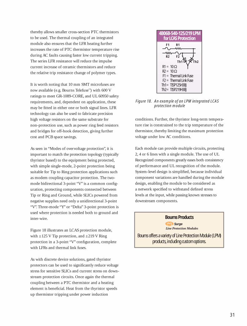
Figure 18. An example of an LPM integrated LCAS protection module
R1F1
F2
Th1 Th2
R2
R1 = 10 ΩR2 = 10 ΩF1 = Thermal Link FuseF2 = Thermal Link Fuse
Th1 = TISP125H3BJTh2 = TISP219H3BJ
4B06B-540-125/219 LPMfor LCAS Protection
Bourns Products
Bourns offers a variety of Line Protection Module (LPM)products, including custom options.
SurgeLine Protection Modules
thereby allows smaller cross-section PTC thermistors
to be used. The thermal coupling of an integrated
module also ensures that the LFR heating further
increases the rate of PTC thermistor temperature rise
during AC faults causing faster low current tripping.
The series LFR resistance will reduce the impulse
current increase of ceramic thermistors and reduce
the relative trip resistance change of polymer types.
It is worth noting that 10 mm SMT microfuses are
now available (e.g. Bourns Telefuse™) with 600 V
ratings to meet GR-1089-CORE, and UL 60950 safety
requirements, and, dependent on application, these
may be fitted in either one or both signal lines. LFR
technology can also be used to fabricate precision
high voltage resistors on the same substrate for
non-protection use, such as power ring feed resistors
and bridges for off-hook detection, giving further
cost and PCB space savings.
As seen in “Modes of overvoltage protection”, it is
important to match the protection topology (typically
thyristor based) to the equipment being protected,
with simple single-mode, 2-point protection being
suitable for Tip to Ring protection applications such
as modem coupling capacitor protection. The two-
mode bidirectional 3-point “V” is a common config-
uration, protecting components connected between
Tip or Ring and Ground, while SLICs powered from
negative supplies need only a unidirectional 3-point
“V”. Three-mode “Y” or “Delta” 3-point protection is
used where protection is needed both to ground and
inter-wire.
Figure 18 illustrates an LCAS protection module,
with ±125 V Tip protection, and ±219 V Ring
protection in a 3-point “V” configuration, complete
with LFRs and thermal link fuses.
As with discrete device solutions, gated thyristor
protectors can be used to significantly reduce voltage
stress for sensitive SLICs and current stress on down-
stream protection circuits. Once again the thermal
coupling between a PTC thermistor and a heating
element is beneficial. Heat from the thyristor speeds
up thermistor tripping under power induction
conditions. Further, the thyristor long-term tempera-
ture rise is constrained to the trip temperature of the
thermistor, thereby limiting the maximum protection
voltage under low AC conditions.
Each module can provide multiple circuits, protecting
2, 4 or 6 lines with a single module. The use of UL
Recognized components greatly eases both consistency
of performance and UL recognition of the module.
System-level design is simplified, because individual
component variations are handled during the module
design, enabling the module to be considered as
a network specified to withstand defined stress
levels at the input, while passing known stresses to
downstream components.

32
GDT OperationBourns® GDTs prevent damage from transient
disturbances by acting as a “crowbar”, i.e. a short
circuit. When an electrical surge exceeds the GDT’s
defined sparkover voltage level (surge breakdown
voltage), the GDT becomes ionized, and conduction
takes place within a fraction of a microsecond. When
the surge passes and the system voltage returns to
normal levels, the GDT returns to its high-impedance
(off) state.
Bourns GDT Features• Unmatched performance and reliability
• Various lead configurations
• Smallest size in the industry (Mini 2-Pole and MINI TRIGARD™)
• Very high surge handling capability
• Extremely low work function for long service life
• Low capacitance & insertion loss
• Highly symmetrical cross-ionization
• Non-radioactive materials
• Optional Switch-Grade Fail-Short
• “Crowbar” function to less than 10 V arc voltage
• Telcordia, RUS, ITU-T, IEC, IEEE and UL compliant
• Broadband network capable
• Through-hole, SMT and cassette mounting types available
• Surge Protector Test Set (Model 4010-01) availablefor GDTs and other technologies
Selection Guide
Max.DC No. of Single
Max.Max.
Switch- Min. Surge
Model Sparkover ofDimensions
SurgeSurge
ACGrade
CapacitanceLife Rating
Voltage Electrodes(Dia. x Length)
RatingRating
RatingFail-Short (10/1000 µs
(8/20 µs)(8/20 µs) Operation waveshape)
2026-07 75 V2026-09 90 V2026-15 150 V2026-20 200 V2026-23 230 V2026-25 250 V
3 8 mm x 11.2 mm 40 kA 10 x 20 kA 10 x 20 A rms, Yes <2 pF 400 x 1000 A2026-30 300 V1 s2026-35 350 V
2026-40 400 V2026-42 420 V2026-47 470 V2026-60 600 V
2036-07 75 V2036-09 90 V2036-15 150 V2036-20 200 V2036-23 230 V2036-25 250 V
3 5 mm x 7.5 mm 20 kA 10 x 10 kA 10 x 10 A rms, Yes <2 pF 500 x 200 A2036-30 300 V1 s2036-35 350 V
2036-40 400 V2036-42 420 V2036-47 470 V2036-60 600 V
The rated discharge current for 3-Electrode GDTs is the total current equally divided between each line to ground.
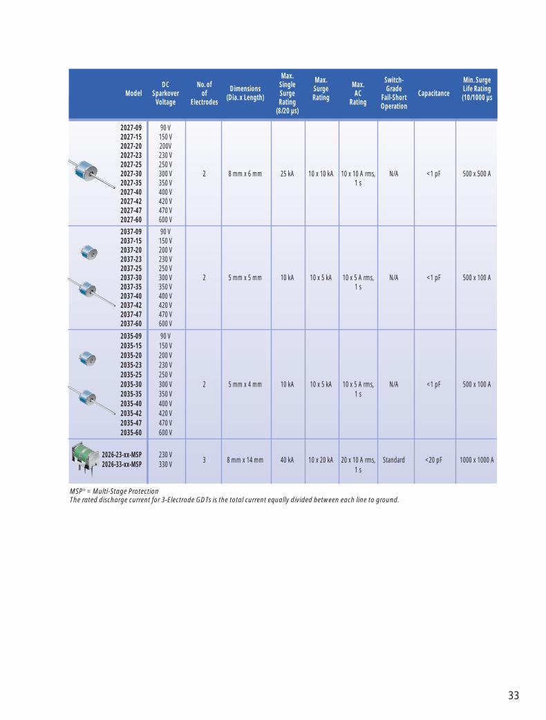
33
Max.DC No. of Single
Max.Max.
Switch- Min. Surge
Model Sparkover ofDimensions
SurgeSurge
ACGrade
CapacitanceLife Rating
Voltage Electrodes(Dia. x Length)
RatingRating
RatingFail-Short (10/1000 µs
(8/20 µs)Operation
2027-09 90 V2027-15 150 V2027-20 200V2027-23 230 V2027-25 250 V2027-30 300 V 2 8 mm x 6 mm 25 kA 10 x 10 kA 10 x 10 A rms, N/A <1 pF 500 x 500 A2027-35 350 V 1 s2027-40 400 V2027-42 420 V2027-47 470 V2027-60 600 V
2037-09 90 V2037-15 150 V2037-20 200 V2037-23 230 V2037-25 250 V2037-30 300 V 2 5 mm x 5 mm 10 kA 10 x 5 kA 10 x 5 A rms, N/A <1 pF 500 x 100 A2037-35 350 V 1 s2037-40 400 V2037-42 420 V2037-47 470 V2037-60 600 V
2035-09 90 V2035-15 150 V2035-20 200 V2035-23 230 V2035-25 250 V2035-30 300 V 2 5 mm x 4 mm 10 kA 10 x 5 kA 10 x 5 A rms, N/A <1 pF 500 x 100 A2035-35 350 V 1 s2035-40 400 V2035-42 420 V2035-47 470 V2035-60 600 V
2026-23-xx-MSP 230 V3 8 mm x 14 mm 40 kA 10 x 20 kA 20 x 10 A rms, Standard <20 pF 1000 x 1000 A
2026-33-xx-MSP 330 V1 s
MSP® = Multi-Stage ProtectionThe rated discharge current for 3-Electrode GDTs is the total current equally divided between each line to ground.

34
Bourns’ range of Multifuse® Polymer PTCs have
been designed to limit overcurrents in telecommuni-
cation equipment as well as many other types of
equipment. Adequate overcurrent protection is
needed to allow equipment to comply with
international standards. Overcurrents can be caused
by AC power or lightning flash disturbances that are
induced or conducted on to the telephone line. Our
extensive range offers multiple voltage variants to
suit specific application requirements. Our devices
are available in surface mount, radial, disk and strap
type packages.
Product Part Vmax Ihold Imax Rmin Rmax R1max Pd Telecom
Series Number (V) (A) (I) (Ω) (Ω) (Ω) (W) Standards
MF-R/90 MF-R055/90 90 0.55 10.0 0.450 0.900 2.000 2.00 N/AMF-R055/90U 90 0.55 10.0 0.450 0.900 2.000 2.00MF-R075/90 90 0.75 10.0 0.370 0.750 1.650 2.00
MF-R/250 MF-R008/250 250 0.08 3.0 14.000 20.000 33.000 1.00 ITU-T K.20/21/45 MF-R011/250 250 0.11 3.0 5.000 9.000 16.000 1.00MF-R012/250 250 0.12 3.0 4.000 8.000 16.000 1.00 GR-1089 MF-R012/250-A 250 0.12 3.0 7.000 9.000 16.000 1.00 IntrabuildingMF-R012/250-C 250 0.12 3.0 5.500 7.500 16.000 1.00MF-R012/250-F 250 0.12 3.0 6.000 10.500 16.000 1.00MF-R012/250-1 250 0.12 3.0 6.000 9.000 16.000 1.00MF-R012/250-2 250 0.12 3.0 8.000 10.500 16.000 1.00MF-R012/250-80 250 0.12 3.0 4.000 8.000 16.000 1.00MF-R014/250 250 0.14 3.0 3.000 6.000 14.000 1.00MF-R014/250-A 250 0.14 3.0 3.000 5.500 12.000 1.00MF-R014/250-B 250 0.14 3.0 4.500 6.000 14.000 1.00MF-R018/250 250 0.18 10.0 0.800 2.000 4.000 1.00
MF-SM/250 MF-SM013/250 250 0.13 3.0 6.000 12.000 20.000 3.00 ITU-T K.20/21/45 MF-SM013/250-A 250 0.13 3.0 6.500 9.000 20.000 3.00MF-SM013/250-B 250 0.13 3.0 9.000 12.000 20.000 3.00 GR-1089 MF-SM013/250-C 250 0.13 3.0 7.000 10.000 20.000 3.00 IntrabuildingMF-SM013/250-D 250 0.13 3.0 7.000 9.000 20.000 3.00MF-SM013/250V 250 0.13 3.0 4.000 7.000 20.000 3.00
MF-D/250 MF-D008/250 250 0.08 3.0 14.000 20.000 33.000 1.00 ITU-T K.20/21/45 MF-D011/250 250 0.11 3.0 5.000 9.000 16.000 1.00MF-D012/250 250 0.12 3.0 4.000 8.000 16.000 1.00 GR-1089MF-D013/250 250 0.13 3.0 6.000 12.000 20.000 1.00 IntrabuildingMF-D014/250 250 0.14 3.0 3.000 6.000 14.000 1.00MF-D018/250 250 0.18 10.0 0.800 2.000 4.000 1.00
Device Options: Packaging Options:• Coated or Uncoated • Custom specified resistance bands • Bulk packed• Un-Tripped or Pre-Tripped • Resistance sort to 0.5 ohm bins • Tape and reel• Narrow resistance bands • Disks with and without solder coating • Custom lead lengths
R1220T
50 5
Selection Guide

35
Our world-class TISP® Thyristor Surge Protectors are
designed to limit overvoltages on telephone lines.
Adequate overvoltage protection is needed to allow
equipment to comply with international standards.
Overvoltages can be caused by AC power or lightning
flash disturbances that are induced or conducted on
to the telephone line. Our extensive range offers
multiple voltage variants to suit specific application
requirements. Our devices are available in surface-
mount or through-hole packages and are guaranteed
to withstand international lightning surges.
Standoff Protection IPPSM Ratings for Lightning Surge Standards
Delivery Voltage Voltage GR-1089-CORE ANSI C62.41 ITU-T K.20/45/21DeviceOptions VDRM V(BO) 2/10 µs 10/1000 µs 8/20 µs 5/310 µs
V V A A A A
TISP1072F3 DR, P, SL 58 72 80 35 70 50TISP1082F3 DR, P, SL 66 82 80 35 70 50
TISP1xxx Series - Dual Unidirectional Overvoltage Protectors
Standoff Protection IPPSM Ratings for Lightning Surge Standards
Delivery Voltage Voltage GR-1089-CORE ANSI C62.41 ITU-T K.20/45/21DeviceOptions VDRM V(BO) 2/10 µs 10/1000 µs 8/20 µs 5/310 µs
V V A A A A
TISPL758LF3 DR 105, 180 130, 220 175 35 120 50TISP3072F3 DR, P, SL 58 72 80 35 70 50TISP3082F3 DR, P, SL 66 82 80 35 70 50TISP3125F3 DR, P, SL 100 125 175 35 120 50TISP3150F3 DR, P, SL 120 150 175 35 120 50TISP3180F3 DR, P, SL 145 180 175 35 120 50TISP3240F3 DR, P, SL 180 240 175 35 120 50TISP3260F3 DR, P, SL 200 260 175 35 120 50TISP3290F3 DR, P, SL 220 290 175 35 120 50TISP3320F3 DR, P, SL 240 320 175 35 120 50TISP3380F3 DR, P, SL 270 380 175 35 120 50TISP3600F3 SL 420 600 190 45 175 70TISP3700F3 SL 500 700 190 45 175 70
TISP3070H3 SL 58 70 500 100 300 200TISP3080H3 SL 65 80 500 100 300 200TISP3095H3 SL 75 95 500 100 300 200TISP3115H3 SL 90 115 500 100 300 200TISP3125H3 SL 100 125 500 100 300 200TISP3135H3 SL 110 135 500 100 300 200TISP3145H3 SL 120 145 500 100 300 200TISP3180H3 SL 145 180 500 100 300 200TISP3210H3 SL 160 210 500 100 300 200TISP3250H3 SL 190 250 500 100 300 200TISP3290H3 SL 220 390 500 100 300 200TISP3350H3 SL 275 350 500 100 300 200
TISP3xxx Series - Dual Bidirectional Overvoltage Protectors
Selection Guide

36
IPPSM Ratings for Lightning Surge Standards
Standoff Protection TIA/EIA-IS-968Delivery Voltage Voltage GR-1089-CORE (FCC PART 68) ITU-T K.20/45/21DeviceOptions VDRM V(BO) 2/10 µs 10/1000 µs 10/560 µs 5/310 µs
V V A A A A
TISP4072F3 LM, LMR, LMFR 58 72 80 35 60 50TISP4082F3 LM, LMR, LMFR 66 82 80 35 60 50TISP4125F3 LM, LMR, LMFR 100 125 175 35 60 50TISP4150F3 LM, LMR, LMFR 120 150 175 35 60 50TISP4180F3 LM, LMR, LMFR 145 180 175 35 60 50TISP4240F3 LM, LMR, LMFR 180 240 175 35 60 50TISP4260F3 LM, LMR, LMFR 200 260 175 35 60 50TISP4290F3 LM, LMR, LMFR 220 290 175 35 60 50TISP4320F3 LM, LMR, LMFR 240 320 175 35 60 50TISP4380F3 LM, LMR, LMFR 270 380 175 35 60 50TISP4600F3 LM, LMR, LMFR 420 600 190 45 110 70TISP4700F3 LM, LMR, LMFR 500 700 190 45 110 70
TISP4xxxF3 Series (35 A 10/1000 µs, 150 mA IH) - Single Bidirectional Overvoltage Protectors
IPPSM Ratings for Lightning Surge Standards
Standoff Protection Holding TIA/EIA-IS-968Delivery Voltage Voltage Current GR-1089-CORE (FCC PART 68) ITU-T K.20/45/21DeviceOptions VDRM V(BO) IH 2/10 µs 10/1000 µs 10/560 µs 5/310 µs
V V mA A A A A
TISP4015L1 AJR, BJR 8 15 50 150 30 35 45TISP4030L1 AJR, BJR 15 30 50 150 30 35 45TISP4040L1 AJR, BJR 25 40 50 150 30 35 45
TISP4070L3 AJR 58 70 150 125 30 40 50TISP4080L3 AJR 65 80 150 125 30 40 50TISP4090L3 AJR 70 90 150 125 30 40 50TISP4125L3 AJR 100 125 150 125 30 40 50TISP4145L3 AJR 120 145 150 125 30 40 50TISP4165L3 AJR 135 165 150 125 30 40 50TISP4180L3 AJR 145 180 150 125 30 40 50TISP4220L3 AJR 160 220 150 125 30 40 50TISP4240L3 AJR 180 240 150 125 30 40 50TISP4260L3 AJR 200 260 150 125 30 40 50TISP4290L3 AJR 230 290 150 125 30 40 50
TISP4xxxLx Series (30 A 10/1000 µs, 50 & 150 mA IH) - Single Bidirectional Overvoltage Protectors
Standoff Protection IPPSM Ratings for Lightning Surge Standards
Delivery Voltage Voltage GR-1089-CORE ANSI C62.41 ITU-T K.20/45/21DeviceOptions VDRM V(BO) 2/10 µs 10/1000 µs 8/20 µs 5/310 µs
V V A A A A
TISP3070T3 BJR 58 70 250 80 250 120TISP3080T3 BJR 65 80 250 80 250 120TISP3095T3 BJR 75 95 250 80 250 120TISP3115T3 BJR 90 115 250 80 250 120TISP3125T3 BJR 100 125 250 80 250 120TISP3145T3 BJR 120 145 250 80 250 120TISP3165T3 BJR 135 165 250 80 250 120TISP3180T3 BJR 145 180 250 80 250 120TISP3200T3 BJR 155 200 250 80 250 120TISP3219T3 BJR 180 219 250 80 250 120TISP3250T3 BJR 190 250 250 80 250 120TISP3290T3 BJR 220 290 250 80 250 120TISP3350T3 BJR 275 350 250 80 250 120TISP3395T3 BJR 320 395 250 80 250 120
TISP3xxx Series - Dual Bidirectional Overvoltage Protectors (Continued)

37
IPPSM Ratings for Lightning Surge Standards
Standoff Protection TIA/EIA-IS-968Delivery Voltage Voltage GR-1089-CORE (FCC PART 68) ITU-T K.20/45/21DeviceOptions VDRM V(BO) 2/10 µs 10/1000 µs 10/560 µs 5/310 µs
V V A A A A
TISP4070M3 AJR, BJR, LM, LMR, LMFR 58 70 300 50 75 100TISP4080M3 AJR, BJR, LM, LMR, LMFR 65 80 300 50 75 100TISP4095M3 AJR, BJR, LM, LMR, LMFR 75 95 300 50 75 100TISP4115M3 AJR, BJR, LM, LMR, LMFR 90 115 300 50 75 100TISP4125M3 AJR, BJR, LM, LMR, LMFR 100 125 300 50 75 100TISP4145M3 AJR, BJR, LM, LMR, LMFR 120 145 300 50 75 100TISP4165M3 AJR, BJR, LM, LMR, LMFR 135 165 300 50 75 100TISP4180M3 AJR, BJR, LM, LMR, LMFR 145 180 300 50 75 100TISP4200M3 AJR, BJR 155 200 300 50 75 100TISP4219M3 BJR 180 219 300 50 75 100TISP4220M3 AJR, BJR, LM, LMR, LMFR 160 220 300 50 75 100TISP4240M3 AJR, BJR, LM, LMR, LMFR 180 240 300 50 75 100TISP4250M3 AJR, BJR, LM, LMR, LMFR 190 250 300 50 75 100TISP4260M3 LM, LMR, LMFR 200 260 300 50 75 100TISP4265M3 AJR, BJR, LM, LMR, LMFR 200 265 300 50 75 100TISP4290M3 AJR, BJR, LM, LMR, LMFR 220 290 300 50 75 100TISP4300M3 AJR, BJR, LM, LMR, LMFR 230 300 300 50 75 100TISP4350M3 AJR, BJR, LM, LMR, LMFR 275 350 300 50 75 100TISP4360M3 AJR, BJR, LM, LMR, LMFR 290 360 300 50 75 100TISP4395M3 AJR, BJR, LM, LMR, LMFR 320 395 300 50 75 100TISP4400M3 BJR, LM, LMR, LMFR 300 400 300 50 75 100
TISP4350MM AJR, BJR 230 300 250 50 55 65TISP4350MM AJR, BJR 275 350 250 50 55 65TISP4360MM AJR, BJR 290 360 250 50 55 65
TISP4xxxMx Series (50 A 10/1000 µs, 150 mA IH) - Single Bidirectional Overvoltage Protectors
IPPSM Ratings for Lightning Surge Standards
Standoff Protection TIA/EIA-IS-968Delivery Voltage Voltage GR-1089-CORE (FCC PART 68) ITU-T K.20/45/21DeviceOptions VDRM V(BO) 2/10 µs 10/1000 µs 10/560 µs 5/310 µs
V V A A A A
TISP4290T3 BJR 220 290 250 80 100 120TISP4350T3 BJR 275 350 250 80 100 120
TISP4xxxTx Series (80 A 10/1000 µs, 150 mA IH) - Single Bidirectional Overvoltage Protectors
IPPSM Ratings for Lightning Surge Standards
Standoff Protection Holding TIA/EIA-IS-968Delivery Voltage Voltage Current GR-1089-CORE (FCC PART 68) ITU-T K.20/45/21DeviceOptions VDRM V(BO) IH 2/10 µs 10/1000 µs 10/560 µs 5/310 µs
V V mA A A A A
TISP4320L3 AJR 240 320 150 125 30 40 50TISP4350L3 AJR 275 350 150 125 30 40 50TISP4360L3 AJR 290 360 150 125 30 40 50TISP4395L3 AJR 320 395 150 125 30 40 50TISP4070L3 BJR 58 70 150 30 40TISP4350L3 BJR 275 350 150 30 40
TISP4xxxLx Series (30 A 10/1000 µs, 50 & 150 mA IH) - Single Bidirectional Overvoltage Protectors (Continued)

38
IPPSM Ratings for Lightning Surge Standards
Standoff Protection Holding TIA/EIA-IS-968Delivery Voltage Voltage Current GR-1089-CORE (FCC PART 68) ITU-T K.20/45/21DeviceOptions VDRM V(BO) IH 2/10 µs 10/1000 µs 10/560 µs 5/310 µs
V V mA A A A A
TISP4015H1 BJR 8 15 50 500 100 125 150TISP4030H1 BJR 15 30 50 500 100 125 150TISP4040H1 BJR 25 40 50 500 100 125 150
TISP4070H3 BJR, LM, LMR, LMFR 58 70 150 500 100 160 200TISP4080H3 BJR, LM, LMR, LMFR 65 80 150 500 100 160 200TISP4095H3 BJR, LM, LMR, LMFR 75 95 150 500 100 160 200TISP4115H3 BJR, LM, LMR, LMFR 90 115 150 500 100 160 200TISP4125H3 BJR, LM, LMR, LMFR 100 125 150 500 100 160 200TISP4145H3 BJR, LM, LMR, LMFR 120 145 150 500 100 160 200TISP4165H3 BJR, LM, LMR, LMFR 135 165 150 500 100 160 200TISP4180H3 BJR, LM, LMR, LMFR 145 180 150 500 100 160 200TISP4200H3 BJR, LM, LMR, LMFR 155 200 150 500 100 160 200TISP4219H3 BJR 180 219 150 500 100 160 200TISP4220H3 BJR 160 220 150 500 100 160 200TISP4240H3 BJR, LM, LMR, LMFR 180 240 150 500 100 160 200TISP4250H3 BJR, LM, LMR, LMFR 190 250 150 500 100 160 200TISP4260H3 LM, LMR, LMFR 200 260 150 500 100 160 200TISP4265H3 BJR 200 265 150 500 100 160 200TISP4290H3 BJR, LM, LMR, LMFR 220 290 150 500 100 160 200TISP4300H3 BJR, LM, LMR, LMFR 230 300 150 500 100 160 200TISP4350H3 BJR, LM, LMR, LMFR 275 350 150 500 100 160 200TISP4360H3 BJR 290 360 150 500 100 160 200TISP4395H3 BJR, LM, LMR, LMFR 320 395 150 500 100 160 200TISP4400H3 BJR, LM, LMR, LMFR 300 400 150 500 100 160 200TISP4500H3 BJR 350 500 150 - - - 200
TISP4165H4 BJR 135 165 225 500 100 160 200TISP4180H4 BJR 145 180 225 500 100 160 200TISP4200H4 BJR 155 200 225 500 100 160 200TISP4265H4 BJR 200 265 225 500 100 160 200TISP4300H4 BJR 230 300 225 500 100 160 200TISP4350H4 BJR 270 350 225 500 100 160 200
TISP4xxxHx Series (100 A 10/1000 µs, 150 & 225 mA IH) - Single Bidirectional Overvoltage Protectors
IPPSM Ratings for Lightning Surge Standards
Standoff Protection TIA/EIA-IS-968Delivery Voltage Voltage GR-1089-CORE (FCC PART 68) ITU-T K.20/45/21DeviceOptions VDRM V(BO) 2/10 µs 10/1000 µs 10/560 µs 5/310 µs
V V A A A A
TISP4070J1 BJR 58 70 1000 200 300 350TISP4080J1 BJR 65 80 1000 200 300 350TISP4095J1 BJR 75 95 1000 200 300 350TISP4115J1 BJR 90 115 1000 200 300 350TISP4125J1 BJR 100 125 1000 200 300 350TISP4145J1 BJR 120 145 1000 200 300 350TISP4165J1 BJR 135 165 1000 200 300 350TISP4180J1 BJR 145 180 1000 200 300 350TISP4200J1 BJR 155 200 1000 200 300 350TISP4219J1 BJR 180 219 1000 200 300 350TISP4250J1 BJR 190 250 1000 200 300 350TISP4290J1 BJR 220 290 1000 200 300 350TISP4350J1 BJR 275 350 1000 200 300 350TISP4395J1 BJR 320 395 1000 200 300 350
TISP4xxxJx Series (200 A 10/1000 µs, 20 mA IH) - Single Bidirectional Overvoltage Protectors

39
IPPSM Ratings for Lightning Surge Standards
Standoff Protection TIA/EIA-IS-968 Delivery Voltage Voltage GR-1089-CORE (FCC PART 68) ITU-T K.20/45/21DeviceOptions VDRM V(BO) 2/10 µs 10/1000 µs 10/160 µs 5/310 µs
V V A A A A
TISP5070H3 BJR -58 -70 500 100 250 200TISP5080H3 BJR -65 -80 500 100 250 200TISP5095H3 BJR -75 -95 500 100 160 200TISP5110H3 BJR -80 -110 500 100 250 200TISP5115H3 BJR -90 -115 500 100 250 200TISP5150H3 BJR -120 -150 500 100 250 200
TISP5xxx Series - Single Unidirectional Overvoltage Protectors
Standoff Protection IPPSM Ratings for Lightning Surge Standards
Delivery Voltage Voltage GR-1089-CORE ANSI C62.41 ITU-T K.20/45/21DeviceOptions VDRM V(BO) 2/10 µs 10/1000 µs 8/20 µs 5/310 µs
V V A A A A
TISP7015 DR 8 15 30 150 40TISP7038 DR 28 38 30 150 40TISP7072F3 DR, P, SL 58 72 85 45 80 70TISP7082F3 DR, P, SL 66 82 85 45 80 70TISP7125F3 DR, P, SL 100 125 190 45 175 70TISP7150F3 DR, P, SL 120 150 190 45 175 70TISP7180F3 DR, P, SL 145 180 190 45 175 70TISP7240F3 DR, P, SL 180 240 190 45 175 70TISP7260F3 DR, P, SL 200 260 190 45 175 70TISP7290F3 DR, P, SL 220 290 190 45 175 70TISP7320F3 DR, P, SL 240 320 190 45 175 70TISP7350F3 DR, P, SL 275 350 190 45 175 70TISP7380F3 DR, P, SL 270 380 190 45 175 70TISP7070H3 SL 58 70 500 100 350 200TISP7080H3 SL 65 80 500 100 350 200TISP7095H3 SL 75 95 500 100 350 200TISP7125H3 SL 100 125 500 100 350 200TISP7135H3 SL 110 135 500 100 350 200TISP7145H3 SL 120 145 500 100 350 200TISP7165H3 SL 130 165 500 100 350 200TISP7180H3 SL 145 180 500 100 350 200TISP7200H3 SL 150 200 500 100 350 200TISP7210H3 SL 160 210 500 100 350 200TISP7220H3 SL 160 210 500 100 350 200TISP7250H3 SL 200 250 500 100 350 200TISP7290H3 SL 230 290 500 100 350 200TISP7350H3 SL 275 350 500 100 350 200TISP7400H3 SL 300 400 500 100 350 200
TISP7xxx Series - Triple Element Bidirectional Overvoltage Protectors

40
Standoff Protection IPPSM Ratings for Lightning Surge Standards
Delivery Voltage Voltage GR-1089-CORE ANSI C62.41 ITU-T K.20/45/21DeviceOptions VDRM V(BO) 2/10 µs 10/1000 µs 8/20 µs 5/310 µs
V V A A A A
TISP61060 DR, P Programmable -5 to -85 50 30 -TISP61089 DR, P Programmable 0 to -85 120 30 - 40TISP61089S DR Programmable 0 to -85 120 30 - 40TISP61089A DR, P Programmable 0 to -120 120 30 - 40TISP61089AS DR Programmable 0 to -120 120 30 - 40TISP61089B DR Programmable 0 to -170 120 30 - 40TISP61511 DR Programmable 0 to -85 170 30 90 40TISP61512 P Programmable 0 to -85 170 30 90 40TISP61521 DR Programmable 0 to -170 170 30 100 40TISPPBL1 DR, P, SE Programmable 0 to -90 100 30 - 40TISPPBL2 DR, P Programmable 0 to -90 100 30 - 40TISPPBL2S DR Programmable 0 to -90 100 30 - 40TISPPBL3 DR Programmable 0 to -170 100 30 - 40
TISP6xxx Series - Dual Programmable Overvoltage Protectors
Standoff Protection IPPSM Ratings for Lightning Surge Standards
Delivery Voltage Voltage GR-1089-CORE ANSI C62.41 ITU-T K.20/45/21DeviceOptions VDRM V(BO) 2/10 µs 10/1000 µs 8/20 µs 5/310 µs
V V A A A A
TISP6NTP2A DR Programmable 0 to -90 85 20 60 25TISP6NTP2B DR Programmable 0 to -120 70 20 60 25
TISP6NTP2x Series - Dual Programmable Overvoltage Protectors
Standoff Protection IPPSM Ratings for Lightning Surge Standards
Delivery Voltage Voltage GR-1089-CORE ITU-T K.20/45/21DeviceOptions VDRM V(BO) 2/10 µs 10/1000 µs 5/310 µs
V V A A A
TISP8250 DR 250 340 75 30 40
TISP8250 - Programmable Unidirectional Overvoltage Protectors
Standoff Protection Holding IPPSM Ratings for Lightning Surge Standards
Delivery Voltage Voltage Current GR-1089-CORE ITU-T K.20/45/21DeviceOptions VDRM V(BO) IH 2/10 µs 10/1000 µs 5/310 µs
V V mA A A A
TISP8200M DR Programmable 0 to -90 -150 -45 -210 -70TISP8201M DR Programmable 0 to +90 +20 +45 +210 +70
TISP820xM Series - Dual Unidirectional Reverse Blocking Programmable Overvoltage Protectors
Standoff Protection IPPSM Ratings for Lightning Surge Standards
Delivery Voltage Voltage GR-1089-CORE ANSI C62.41 ITU-T K.20/45/21DeviceOptions VDRM V(BO) 10/1000 µs 8/20 µs 5/310 µs
V V A A A
TISP83121 DR Programmable 0 to ±100 150 500 150
TISP83121 Series - Dual-Gate Unidirectional Overvoltage Protectors

41
Features• Precision thick-film technology
• Withstands lightning and AC power cross
• Complies with Telcordia (Bellcore) GR-1089 requirements
• Complies with ITU-T K.20 requirements
• Surface mount solution
• Guaranteed to fail safely under fault conditions
• Optional one-shot thermal fuse
• Optional resettable PTC
• UL 497A recognized
• Non-flammable
• Standard offerings
• Custom designs
• Full qualification test capabilities
• Central Office, Remote and Customer Premise Equipment applications include:
- Analog linecards - xDSL linecards- Pairgain - VoIP- PBX systems - External and- LCAS protection intra-buildings
Custom DesignsIn addition to the various standard off-the-shelf
versions available, Bourns offers extensive custom
options. Examples include:
• Variety of packages, e.g. vertical and horizontal SMD
• Packaging options, e.g. trays, tape and reel, bulk
• Additional resistors, e.g. ringing power resistors
• Additional components, e.g. fuses, PTCs,
overvoltage protection
• Resistors from 5.6 Ω• Ratio matching: down to 0.3 %, or less with
special limitations
Selection Guide
SurgeLine Protection Modules
Model Schematic Dimensions Description
• 2x 50 Ω, 1%4B08B-511-500 • 0.5 % matching
• Thermal fuses
• 1x R Ω, 5 %4B04B-502-RC • Values 5.6-100 Ω
• Thermal fuse
• 2x R Ω, 5 %• Values 5.6-100 Ω
4B06B-512-RC • 0.5 % matching• Thermal fuses
3
F1 R1 R2 F2
5 7 8 12 13 15 17
51.05(2.010)MAX.
MAX.
3 5 7 8 12 13 15 17
7.62(.300)
10.16(.400) 2.54
(.100)
.51(.020)
5.08(.200)
3.43 ± .38(.135 ± .015)
11.30(.445)
2.03(.080)MAX.
0.36(.014)
1 2
Functional Schematic*
*User must short pins 9 & 10 on the circuit board. 1 2 9 10
2.54 ± .127(.100 ± .005)
2.54 ± .127(.100 ± .005)
17.78 ± .254(.700 ± .010)
25.40 ± 0.50(1.000 ± .020) 2.03
(.080)MAX.
0.36(.014)MAX.
11.30 ± 0.50(.450 ± .020)
1 2 3 11 12 13
F2F1
R1
R2
1 2 3 11 12 13
1.27(.050)
2.54(.100)
20.32(.800)
33.27(1.310) 3.18
(.125)MAX.
0.36(.014)MAX.
MAX.
MAX.1.27
(.050) 2.29(.090)MAX.
11.43(.450)

42
Model Schematic Dimensions Description
• 2x R Ω, 5 %
4A08P-505-RC• Values 5.6-100 Ω• 1 % matching
• 4x 50 Ω, 1 %4A12P-516-500 • 0.5 % matching
• Thermal fuses
• 2x 50 Ω, 1 %• 1.0 % matching
4B06B-514-500• Resettable
Multifuse® PPTC
• 2x 40 Ω, 2 %• 0.5 % matching
4B07B-530-400 • Integrated overvoltageTISP®
• 2x 10 Ω, 5 %• 2.0 % matching
4B06B-540-125/219 • Integrated overvoltageTISP®
2 3
1 4
22.35 ± .13(0.880 ± .005)
12.70 ± .13(0.500 ± .005)
5.10 ± .13(0.200 ± .005)
0.51 ± .05(0.020 ± .002)
2.54 ± .13(0.100 ± .005)
2.54 ± .13(0.100 ± .005)
2
1
3
4
.38(.015)MAX.
RADIUS
22.35 ± .05(0.880 ± .002)
22.50 ± .38(0.885 ± .015)
4.10 ± .25(0.160 ± .010)
1.270 ± .127(0.050 ± .005)
1.270 ± .127(0.050 ± .005)
1.02 ± .05(0.040 ± .002)
0.25 ± .05(0.010 ± .002)
F1A
F2B
F2A
F1B
R1A
R1B
R2B
R2A
1 2 4 8 10 11
22 21 19 15 13 12
4
4A12P-516-500DCODE
21 8 10 11
32.81(1.292)
3.72(.146)
MAX.
10.16 ± .13(.400 ± .005)
5.08 ± .13(.200 ± .005)
2.54 ± .13(.100 ± .005)
12.70(.500)
14.59(.575)
MAX.
4.07 ± .25(.160 ± .010)
2.80(.110)
7.87(.310)
1 2 4
R1
R3
96 8
R2
R4
12.54
(.100)2 PLCS.
2.54(.100)2 PLCS.
5.08(.200)3 PLCS.
25.65(1.010) 4.32
(.170)MAX.
0.36(.014)MAX.
MAX.
4B06B-514-500DCODE
MAX.3.43 ± .38
(.135 ± .015)
12.32(.485)
2 4 6 8 9
1 2 11
F1
R1
R2
3
F2
12
6,7
4,5
1,813 14
2 35.56(1.400)MAX.
20.32(.800)
APPROXIMATE TISP® LOCATION
APPROXIMATE FUSE LOCATIONS
4.57(.180)MAX.
MAX.
MAX.
1 2 3
4B07B-530-400DCODE
11 12 13 14
2.54(.100)
0.36(.014)
1.91(.075)
MAX.
1.27(.050)
3.43 ± .38(.135 ± .015)
12.70(.500)
61089B
2 PLCS.
5 PLCS.
1 2 11
F1
R1 TISP V(B01) TISP V(B02)
R2
3 12 13
F2
33.02(1.300)MAX.
20.32(.800)
APPROXIMATE TISP® LOCATION
APPROXIMATE FUSE LOCATIONS
4.57(.180)MAX.
MAX.
MAX.
1 2 3
4B06B-540-V /V(B01) (B02)
DCODE
11 12 13
2.54(.100) 0.36
(.014)
0.97(.038)
1.91(.075)
MAX.
1.27(.050)
3.43 ± .38(.135 ± .015)
11.43(.450)
2 PLCS.
4 PLCS.
TISP
TISP

43
Features• Model 1250T is designed for use in telecommuni-
cations circuit applications requiring low current protection with high surge tolerance
• Ideal for protecting Central Office and Customer Premise Equipment, including POTS, T1/E1, ISDNand xDSL circuits
• Model B1250T allows overcurrent compliance with telecom specifications including Telcordia GR-1089, UL 60950, and ITU K.20 and K.21
• Model B0500T is a lower current version for use inapplications where a faster opening time may be required
Selection Guide
Ampere Voltage Peak SurgeRating Rating Current
Model Device Symbol A V 10/1000 A
B1250T 1.25 600 100
B0500T 0.5 600 25
Telefuse™
Telecom Fuses
0.50

“Telefuse” and “MINI TRIGARD” are trademarks of Bourns, Inc.“TISP” is a trademark of Bourns, Ltd., and is Registered in U.S. Patent and Trademark Office.
“Multifuse and MSP” are registered trademarks of Bourns, Inc.“Bourns” is a registered trademark of Bourns, Inc. in the U.S. and other countries.
COPYRIGHT© 2002, BOURNS, INC. LITHO IN U.S.A. DP 11/02 15M/K0115
Worldwide Sales Offices
Country Phone Fax
Benelux: +31-70-3004333 +31-70-3004345China: +86-21-64821250 +86-21-64821249France: +33-254-735151 +33-254-735156Germany: +49-69-80078212 +49-69-80078299Hong Kong: +852-2411 5599 +852-2412 3611Ireland: +44-1276-691087 +44-1276-691088Italy: +39-02-38900041 +39-02-38900042Japan: +81-49-269 3204 +81-49-269 3297Singapore: +65-63461933 +65-63461911Switzerland: +41-41-7685555 +41-41-7685510Taiwan: +886-2-25624117 +886-2-25624116UK: +44-1276-691087 +44-1276-691088USA: +1-909-781-5500 +1-909-781-5006
Non-Listed EuropeanCountries: +41- 41-7685555 +41- 41-7685510
Technical Assistance
Region Phone Fax
Asia-Pacific: +886-2-25624117 +886-2-25624116Europe: +41- 41-7685555 +41- 41-7685510North America: +1-909-781-5500 +1-909-781-5700
www.bourns.comwww.bournscircuitprotection.com
Bourns® products are available through an extensive network of manufacturer’s representatives, agents and distributors.To obtain technical applications assistance, a quotation, or to place an order, contact a Bourns representative in your area.
Circuit Protection Solutions


![Bourns USB Port Protection Final[1]](https://img.pdfslide.us/doc/110x75/577d35431a28ab3a6b8ff398/bourns-usb-port-protection-final1.jpg)