Embed Size (px)
Citation preview
AN914: Using the Si5348 in TelecomBoundary Clock Applications
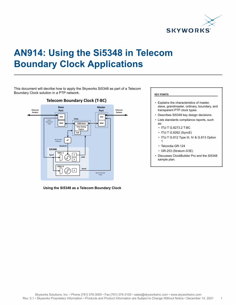
This document will decribe how to apply the Skyworks Si5348 as part of a TelecomBoundary Clock solution in a PTP network.
DSPLL C
SyncE Recovered
Clock
÷
÷
DSPLL D
÷
1PPS
Si5348Serial I/F
uP
EthernetPackets
Servo Loop Software
EthernetPackets
SyncE
Slave Port
Telecom Boundary Clock (T-BC)
SyncE Transmit Clock
SyncE
Time Stamp Engine
ToD
1588 Stack
FPGAPHY
MAC
Master Port
PHY
MAC
KEY POINTS
• Explains the characteristics of master,slave, grandmaster, ordinary, boundary, andtransparent PTP clock types.
• Describes Si5348 key design decisions.• Lists standards compliance reports, such
as:• ITU-T G.8273.2 T-BC• ITU-T G.8262 (SyncE)• ITU-T G.812 Type III, IV & G.813 Option
1• Telcordia GR-124• GR-253 (Stratum-3/3E)
• Discusses ClockBuilder Pro and the Si5348sample plan.
Using the Si5348 as a Telecom Boundary Clock
Skyworks Solutions, Inc. • Phone [781] 376-3000 • Fax [781] 376-3100 • [email protected] • www.skyworksinc.com1 Rev. 0.1 • Skyworks Proprietary Information • Products and Product Information are Subject to Change Without Notice • December 14, 2021 1
1. Overview
1.1 Synchronization
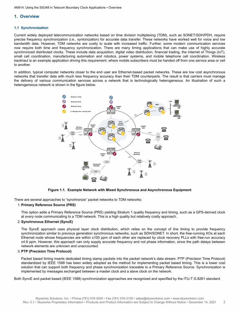
Current widely deployed telecommunication networks based on time division multiplexing (TDM), such as SONET/SDH/PDH, requireprecise frequency synchronization (i.e., syntonization) for accurate data transfer. These networks have worked well for voice and lowbandwidth data. However, TDM networks are costly to scale with increased traffic. Further, some modern communication servicesnow require both time and frequency synchronization. There are many timing applications that can make use of highly accuratesynchronized distributed clocks. These include data acquisition, digital video distribution, financial trading, the Internet of Things (IoT),small cell coordination, manufacturing automation and robotics, power systems, and mobile telephone cell coordination. Wirelessbackhaul is an example application driving this requirement, where mobile subscribers must be handed off from one service area or cellto another.
In addition, typical computer networks closer to the end user are Ethernet-based packet networks. These are low cost asynchronousnetworks that transfer data with much less frequency accuracy than their TDM counterparts. The result is that carriers must managethe delivery of various communication services across a network that is technologically heterogeneous. An illustration of such aheterogeneous network is shown in the figure below.
SONET/SDH
SONET/SDH
BSC/RNC
Wireless Backhaul
T1/E1T1/E1
PBX
SONET/SDH
10G
3G/LTE
3G/LTE
SONET/SDH
OLT
ONT
ResidentialPON/DSL
BSC/RNC
3G/LTE
3G/LTE
10G
3G/LTE
Wireless Backhaul
CorePacket
Network
LAN
WANStratum 3 Clock
Stratum 1 Clock
Stratum 2 Clock
+/- 100 ppm free- running clock
3G/LTE
Figure 1.1. Example Network with Mixed Synchronous and Asynchronous Equipment
There are several approaches to “synchronize” packet networks to TDM networks:1. Primary Reference Source (PRS)
This option adds a Primary Reference Source (PRS) yielding Stratum 1 quality frequency and timing, such as a GPS-derived clockat every node communicating to a TDM network. This is a high quality but relatively costly approach.
2. Synchronous Ethernet (SyncE)
The SyncE approach uses physical layer clock distribution, which relies on the concept of line timing to provide frequencysynchronization similar to previous generation synchronous networks, such as SDH/SONET. In short, the free-running XOs at eachEthernet node whose frequencies are within ±100 ppm of each other are replaced by clock recovery PLLs with free-run accuracy±4.6 ppm. However, this approach can only supply accurate frequency and not phase information, since the path delays betweennetwork elements are unknown and unaccounted.
3. PTP (Precision Time Protocol)
Packet based timing inserts dedicated timing stamp packets into the packet network’s data stream. PTP (Precision Time Protocol)standardized by IEEE 1588 has been widely adopted as the method for implementing packet based timing. This is a lower costsolution that can support both frequency and phase synchronization traceable to a Primary Reference Source. Synchronization isimplemented by messages exchanged between a master clock and a slave clock on the network.
Both SyncE and packet based (IEEE 1588) synchronization approaches are recognized and specified by the ITU-T G.8261 standard.
AN914: Using the Si5348 in Telecom Boundary Clock Applications • Overview
Skyworks Solutions, Inc. • Phone [781] 376-3000 • Fax [781] 376-3100 • [email protected] • www.skyworksinc.com2 Rev. 0.1 • Skyworks Proprietary Information • Products and Product Information are Subject to Change Without Notice • December 14, 2021 2
1.2 PTP (Precision Time Protocol) Network Clock Types
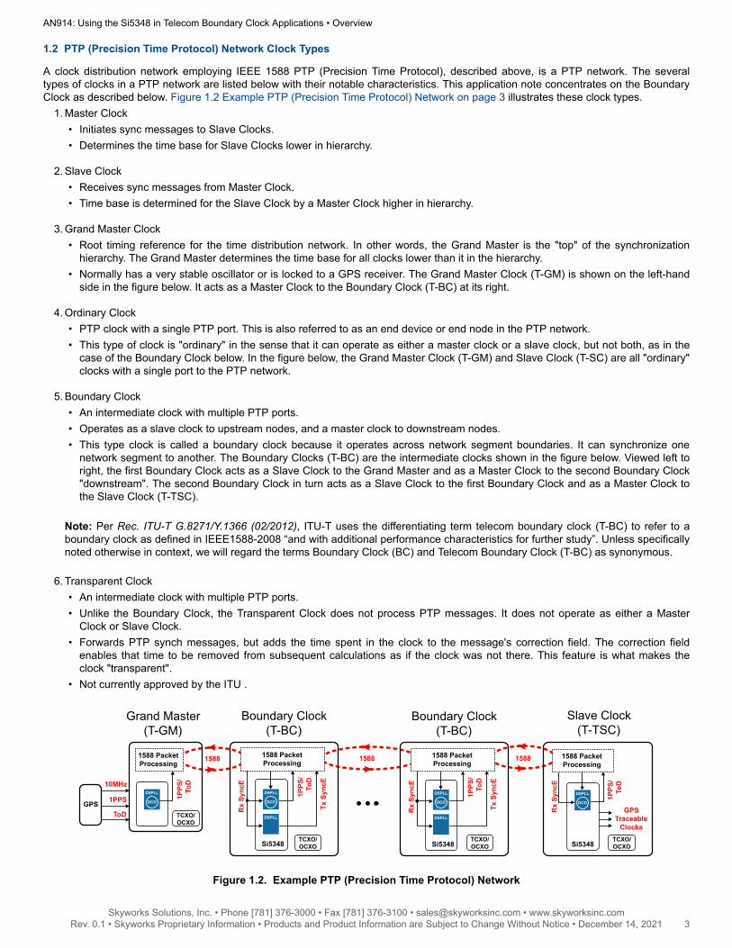
A clock distribution network employing IEEE 1588 PTP (Precision Time Protocol), described above, is a PTP network. The severaltypes of clocks in a PTP network are listed below with their notable characteristics. This application note concentrates on the BoundaryClock as described below. Figure 1.2 Example PTP (Precision Time Protocol) Network on page 3 illustrates these clock types.
1. Master Clock• Initiates sync messages to Slave Clocks.• Determines the time base for Slave Clocks lower in hierarchy.
2. Slave Clock• Receives sync messages from Master Clock.• Time base is determined for the Slave Clock by a Master Clock higher in hierarchy.
3. Grand Master Clock• Root timing reference for the time distribution network. In other words, the Grand Master is the "top" of the synchronization
hierarchy. The Grand Master determines the time base for all clocks lower than it in the hierarchy.• Normally has a very stable oscillator or is locked to a GPS receiver. The Grand Master Clock (T-GM) is shown on the left-hand
side in the figure below. It acts as a Master Clock to the Boundary Clock (T-BC) at its right.
4. Ordinary Clock• PTP clock with a single PTP port. This is also referred to as an end device or end node in the PTP network.• This type of clock is "ordinary" in the sense that it can operate as either a master clock or a slave clock, but not both, as in the
case of the Boundary Clock below. In the figure below, the Grand Master Clock (T-GM) and Slave Clock (T-SC) are all "ordinary"clocks with a single port to the PTP network.
5. Boundary Clock• An intermediate clock with multiple PTP ports.• Operates as a slave clock to upstream nodes, and a master clock to downstream nodes.• This type clock is called a boundary clock because it operates across network segment boundaries. It can synchronize one
network segment to another. The Boundary Clocks (T-BC) are the intermediate clocks shown in the figure below. Viewed left toright, the first Boundary Clock acts as a Slave Clock to the Grand Master and as a Master Clock to the second Boundary Clock"downstream". The second Boundary Clock in turn acts as a Slave Clock to the first Boundary Clock and as a Master Clock tothe Slave Clock (T-TSC).
Note: Per Rec. ITU-T G.8271/Y.1366 (02/2012), ITU-T uses the differentiating term telecom boundary clock (T-BC) to refer to aboundary clock as defined in IEEE1588-2008 “and with additional performance characteristics for further study”. Unless specificallynoted otherwise in context, we will regard the terms Boundary Clock (BC) and Telecom Boundary Clock (T-BC) as synonymous.
6. Transparent Clock• An intermediate clock with multiple PTP ports.• Unlike the Boundary Clock, the Transparent Clock does not process PTP messages. It does not operate as either a Master
Clock or Slave Clock.• Forwards PTP synch messages, but adds the time spent in the clock to the message's correction field. The correction field
enables that time to be removed from subsequent calculations as if the clock was not there. This feature is what makes theclock "transparent".
• Not currently approved by the ITU .
15881588
Grand Master (T-GM)
GPS 1PPS
ToD
10MHzDSPLL
DCO
1PPS
/To
D
1588 Packet Processing
Boundary Clock (T-BC)
Tx S
yncE
Rx
Sync
E
DSPLL
DCO
Si5348
DSPLL
1PPS
/To
D
1588 Packet Processing
Boundary Clock (T-BC)
Tx S
yncE
Rx
Sync
E
DSPLL
DCO
Si5348
DSPLL
1PPS
/To
D
1588 Packet Processing
Slave Clock (T-TSC)
GPSTraceable
Clocks
DSPLL
DCO
Si5348
1PPS
/To
D
1588 Packet Processing
Rx
Sync
E
1588
TCXO/OCXO
TCXO/OCXO
TCXO/OCXO
TCXO/OCXO
Figure 1.2. Example PTP (Precision Time Protocol) Network
AN914: Using the Si5348 in Telecom Boundary Clock Applications • Overview
Skyworks Solutions, Inc. • Phone [781] 376-3000 • Fax [781] 376-3100 • [email protected] • www.skyworksinc.com3 Rev. 0.1 • Skyworks Proprietary Information • Products and Product Information are Subject to Change Without Notice • December 14, 2021 3
1.3 Skyworks Si5348
The Skyworks Si5348 is a monolithic IC with three independent DSPLLs supporting flexible SyncE/IEEE 1588 and SETS (SynchronousEquipment Timing Source) architectures. It provides wander and jitter attenuation on all three DSPLLs.
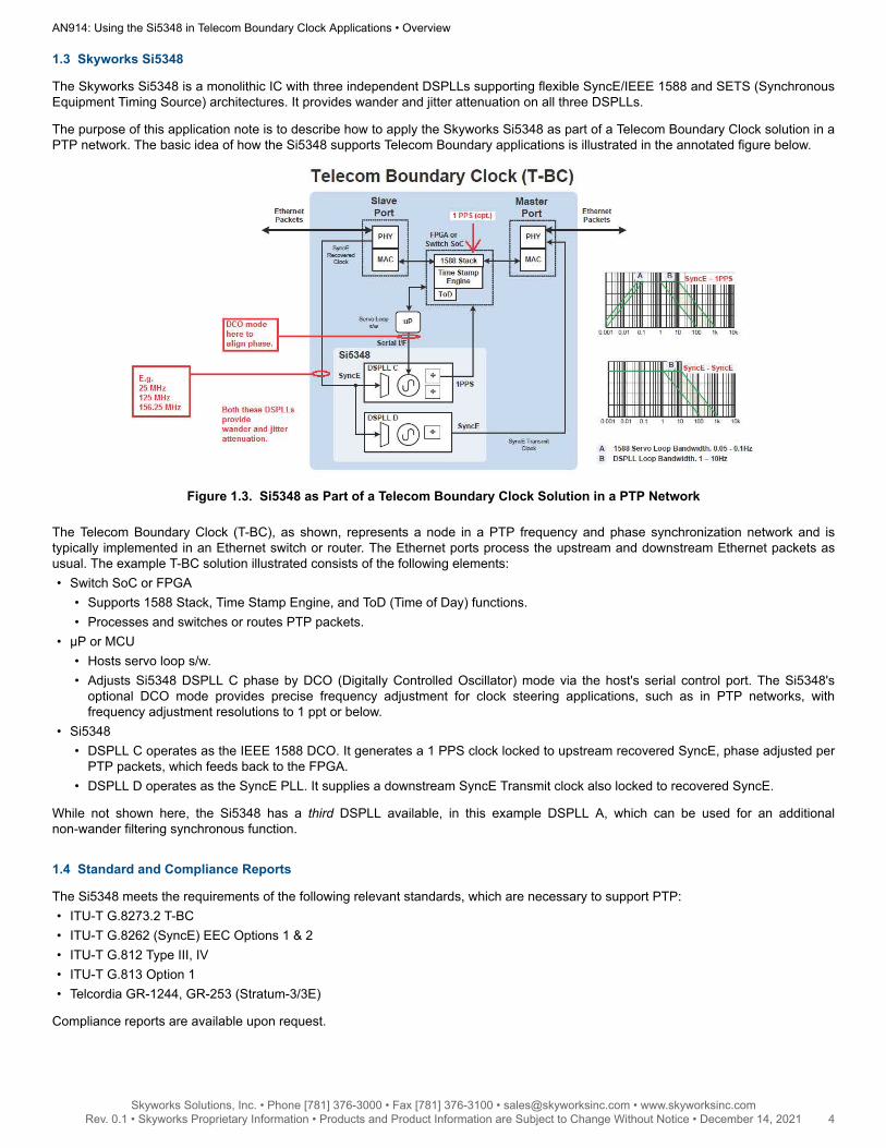
The purpose of this application note is to describe how to apply the Skyworks Si5348 as part of a Telecom Boundary Clock solution in aPTP network. The basic idea of how the Si5348 supports Telecom Boundary applications is illustrated in the annotated figure below.
Figure 1.3. Si5348 as Part of a Telecom Boundary Clock Solution in a PTP Network
The Telecom Boundary Clock (T-BC), as shown, represents a node in a PTP frequency and phase synchronization network and istypically implemented in an Ethernet switch or router. The Ethernet ports process the upstream and downstream Ethernet packets asusual. The example T-BC solution illustrated consists of the following elements:• Switch SoC or FPGA
• Supports 1588 Stack, Time Stamp Engine, and ToD (Time of Day) functions.• Processes and switches or routes PTP packets.
• µP or MCU• Hosts servo loop s/w.• Adjusts Si5348 DSPLL C phase by DCO (Digitally Controlled Oscillator) mode via the host's serial control port. The Si5348's
optional DCO mode provides precise frequency adjustment for clock steering applications, such as in PTP networks, withfrequency adjustment resolutions to 1 ppt or below.
• Si5348• DSPLL C operates as the IEEE 1588 DCO. It generates a 1 PPS clock locked to upstream recovered SyncE, phase adjusted per
PTP packets, which feeds back to the FPGA.• DSPLL D operates as the SyncE PLL. It supplies a downstream SyncE Transmit clock also locked to recovered SyncE.
While not shown here, the Si5348 has a third DSPLL available, in this example DSPLL A, which can be used for an additionalnon-wander filtering synchronous function.
1.4 Standard and Compliance Reports
The Si5348 meets the requirements of the following relevant standards, which are necessary to support PTP:• ITU-T G.8273.2 T-BC• ITU-T G.8262 (SyncE) EEC Options 1 & 2• ITU-T G.812 Type III, IV• ITU-T G.813 Option 1• Telcordia GR-1244, GR-253 (Stratum-3/3E)
Compliance reports are available upon request.
AN914: Using the Si5348 in Telecom Boundary Clock Applications • Overview
Skyworks Solutions, Inc. • Phone [781] 376-3000 • Fax [781] 376-3100 • [email protected] • www.skyworksinc.com4 Rev. 0.1 • Skyworks Proprietary Information • Products and Product Information are Subject to Change Without Notice • December 14, 2021 4
2. Skyworks Si5348 Key Design Decisions
2.1 Reference
The reference clock applied to the reference input determines DSPLL/DCO free-run/holdover accuracy and stability. Therefore refer-ence clock selection is key to Si5348’s output clock wander performance. A TCXO (Temperature Compensated Crystal Oscillator) orOCXO (Oven Controlled Crystal Oscillator) may be considered depending on the level of performance required. The reference clockinput will support clocks in the range of 5 – 250 MHz, similar to the other input clocks.
Please refer to Skyworks application note, AN905: “Si534x External References; Optimizing Performance”, for general informationregarding references for Si534x devices. This particular application note discusses the use of XOs, TCXOs, and OCXOs at the Si534xXA/XB interface only.
2.1.1 TCXO
TCXOs have improved holdover stability and MTIE/TDEV wander performance over temperature versus uncompensated XOs. Theycan be used to help meet Stratum 3 and G.8262 applications. However, they will generally not meet Stratum 3E, or high accuracy 1588applications such as LTE.
2.1.2 OCXO
OCXOs have the best holdover stability and MTIE/TDEV wander performance. OCXOs can be used to meet the most stringent Stratum3E, and 1588 applications, e.g., LTE FDD which requires an accuracy of ±1.5 µs.
The OCXO selected as the reference for the Si5348 should have both good wander and jitter performance. Further, any componentssuch as buffers, in the signal path between the OCXO and the Si5348, should have low additive jitter.
An example suitable OCXO for use with the Si5348 is the Rakon P/N STP3158. This 12.8 MHz oscillator is installed on the SiOCXO1-EB evaluation board. See UG123: "SiOCXO1-EVB Evaluation Board User's Guide".
2.2 XTAL
The crystal applied to the Si5348 crystal inputs XA and XB primarily contributes to the output clock jitter performance. The crystalshould be selected as specified in the datasheet. The allowable range is 48 – 54 MHz. The typical application uses a relatively lowESR 48 MHz crystal. Higher Q crystals yield lower phase noise than lower Q crystals. Recommended crystals are listed in the Si5348Reference Manual.
2.3 Layout and Environmental Considerations
Please refer to both the Si5348 Reference Manual and to application note, AN905: “Si534x External References; Optimizing Perform-ance”, previously cited for XTAL, TCXO, and OCXO layout and environmental recommendations.
AN914: Using the Si5348 in Telecom Boundary Clock Applications • Skyworks Si5348 Key Design Decisions
Skyworks Solutions, Inc. • Phone [781] 376-3000 • Fax [781] 376-3100 • [email protected] • www.skyworksinc.com5 Rev. 0.1 • Skyworks Proprietary Information • Products and Product Information are Subject to Change Without Notice • December 14, 2021 5
2.4 Loop Bandwidths
There are three independent DSPLLs (A, C, and D) available, each of which needs an assigned loop bandwidth selected per itsapplication. The loop bandwidths are programmable from 1 mHz to 4 kHz. The Si5348’s DSPLLs will generally be used as wanderfiltering PLLs in PTP applications, which means relatively narrow bandwidths less than 10 Hz. Common loop BWs for TelecomBoundary Clock applications are in the 0.1 to 10 Hz range. North American customers will select BW = 0.1 Hz per Telecordia, whileEuropean customers will select BWs in the 1 to 10 Hz range per ITU-T.
The Fastlock bandwidths for these DSPLLs may be conveniently set to 10X or more than the operating bandwidth. For example, if theloop bandwidth is set to 0.1 to 10 Hz, then the Fastlock Bandwidth may be set to 100 Hz.
DSPLL B is pre-assigned to the Reference input, which determines the overall wander and hold-over performance of all the outputclocks. An OCXO will typically have good wander performance but not necessarily good jitter performance. For an OCXO with bothgood wander and jitter performance, we can make the DSPLL B loop bandwidth much wider than DSPLLs A, C, and D. (A wide DSPLLB bandwidth helps to suppress wander associated with the crystal.) A suggested target for both the loop bandwidth and the Fastlockbandwidth is 1 kHz. If necessary, this can be increased to 4 kHz for both settings.
However, if an OCXO or the combination of an OCXO plus intervening buffers has poor jitter performance, then some jitter attenuationmay be necessary. In such a case, the DSPLL B loop bandwidth can be decreased to, for example, 100 Hz. Wander and jitter testingwill be needed to confirm the necessary system performance.
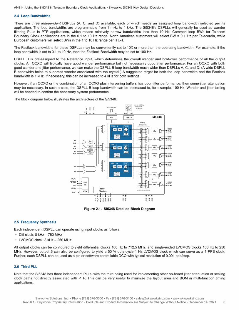
The block diagram below illustrates the architecture of the Si5348.
Si5348
VDD
VDDA
3
OE0
b
OE1
b
OE2
b
5 MHz – 250 MHzTCXO/OCXOor REFCLK
FDEC
FIN
C
REFREFbXBXA
48-54 MHz XTAL
OSC
DSPLL_A
LPFPD
f
DCO
DSPLL_C
LPFPD
÷Mn_C
Md_C
f
DCOIN1
IN1b
IN0
IN0b
IN2
IN2b
÷ P0n
P0d
÷ P1n
P1d
÷ P2n
P2d
A1/SDO
LOL_
Cb
LOL_
Db
INTR
b
StatusMonitors
LOL_
Ab
LOS0
b
LOS1
b
LOS2
b
RSTb
VDDS
Output Crosspoint
ACD
ACD
ACD
ACD
ACD
OUT0bOUT0÷R0
VDDO0
÷R1 OUT1b
VDDO1OUT1
OUT2b
VDDO2OUT2÷R2
÷R3 OUT3b
VDDO3OUT3
÷R4 OUT4b
VDDO4OUT4
÷R5 OUT5b
VDDO5OUT5
÷R6 OUT6b
VDDO6OUT6
ACDR5
÷Mn_A
Md_A
IN3
IN4
SDA/SDIO
SCLK
A0/CSb
I2C_SEL
SPI/I2C
NVM
ACD
DSPLL_D
LPFPD
÷Mn_D
Md_D
f
DCO
DSPLLB
Figure 2.1. Si5348 Detailed Block Diagram
2.5 Frequency Synthesis
Each independent DSPLL can operate using input clocks as follows:• Diff clock: 8 kHz – 750 MHz• LVCMOS clock: 8 kHz – 250 MHz
All output clocks can be configured to yield differential clocks 100 Hz to 712.5 MHz, and single-ended LVCMOS clocks 100 Hz to 250MHz. However, output 6 can also be configured to yield a 50 % duty cycle 1 Hz LVCMOS clock which can serve as a 1 PPS clock.Further, each DSPLL can be used as a pin or software controllable DCO with typical resolution of 0.001 ppb/step.
2.6 Third PLL
Note that the Si5348 has three independent PLLs, with the third being used for implementing other on-board jitter attenuation or scalingclock paths not directly associated with PTP. This can be very useful to minimize the layout area and BOM in multi-function timingapplications.
AN914: Using the Si5348 in Telecom Boundary Clock Applications • Skyworks Si5348 Key Design Decisions
Skyworks Solutions, Inc. • Phone [781] 376-3000 • Fax [781] 376-3100 • [email protected] • www.skyworksinc.com6 Rev. 0.1 • Skyworks Proprietary Information • Products and Product Information are Subject to Change Without Notice • December 14, 2021 6
3. ClockBuilder Pro and the Si5348 Sample Design
ClockBuilder Pro supports the Si5348 network synchronizer clock. The GUI window flow for device configuration is very similar to thatfor all Si534x clock generators and jitter attenuators. There are a few window entries which are different and should be highlighted. TheSi5348 Sample Design refers to the specific example which comes with CBPro.
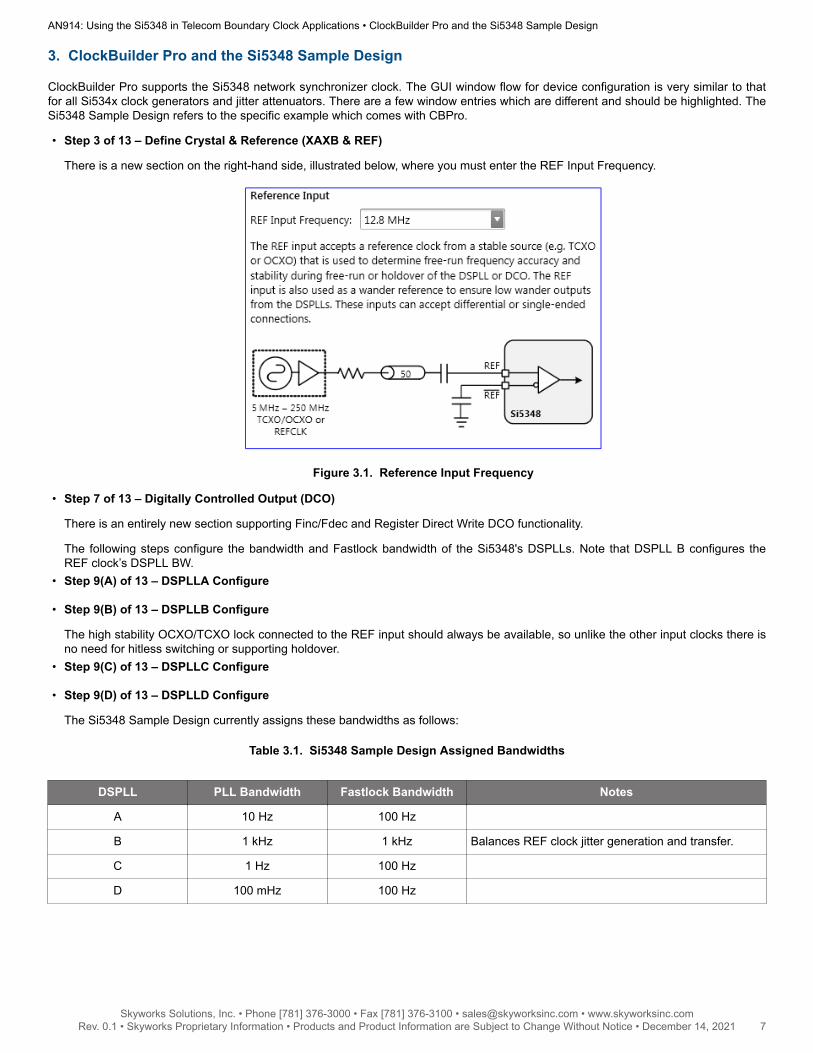
• Step 3 of 13 – Define Crystal & Reference (XAXB & REF)
There is a new section on the right-hand side, illustrated below, where you must enter the REF Input Frequency.
Figure 3.1. Reference Input Frequency
• Step 7 of 13 – Digitally Controlled Output (DCO)
There is an entirely new section supporting Finc/Fdec and Register Direct Write DCO functionality.
The following steps configure the bandwidth and Fastlock bandwidth of the Si5348's DSPLLs. Note that DSPLL B configures theREF clock’s DSPLL BW.
• Step 9(A) of 13 – DSPLLA Configure
• Step 9(B) of 13 – DSPLLB Configure
The high stability OCXO/TCXO lock connected to the REF input should always be available, so unlike the other input clocks there isno need for hitless switching or supporting holdover.
• Step 9(C) of 13 – DSPLLC Configure
• Step 9(D) of 13 – DSPLLD Configure
The Si5348 Sample Design currently assigns these bandwidths as follows:
Table 3.1. Si5348 Sample Design Assigned Bandwidths
DSPLL PLL Bandwidth Fastlock Bandwidth Notes
A 10 Hz 100 Hz
B 1 kHz 1 kHz Balances REF clock jitter generation and transfer.
C 1 Hz 100 Hz
D 100 mHz 100 Hz
AN914: Using the Si5348 in Telecom Boundary Clock Applications • ClockBuilder Pro and the Si5348 Sample Design
Skyworks Solutions, Inc. • Phone [781] 376-3000 • Fax [781] 376-3100 • [email protected] • www.skyworksinc.com7 Rev. 0.1 • Skyworks Proprietary Information • Products and Product Information are Subject to Change Without Notice • December 14, 2021 7
4. Conclusion
The Skyworks Si5348 supports a number of unique features:• Three independent flexible DSPLLs, configurable for SyncE PLL, IEEE 1588 DCO, and general purpose applications.• One dedicated DSPLL for the TCXO/OCXO reference input clock determining overall accuracy and stability.• DCO mode support for clock steering applications.• 1 Hz clock output.
This unique combination of features makes the Si5348 an excellent fit for Telecom Boundary Clock (T-BC) solutions.
AN914: Using the Si5348 in Telecom Boundary Clock Applications • Conclusion
Skyworks Solutions, Inc. • Phone [781] 376-3000 • Fax [781] 376-3100 • [email protected] • www.skyworksinc.com8 Rev. 0.1 • Skyworks Proprietary Information • Products and Product Information are Subject to Change Without Notice • December 14, 2021 8
Copyright © 2021 Skyworks Solutions, Inc. All Rights Reserved.Information in this document is provided in connection with Skyworks Solutions, Inc. (“Skyworks”) products or services. These materials, including the information contained herein, are provided by Skyworks as a service to its customers and may be used for informational purposes only by the customer. Skyworks assumes no responsibility for errors or omissions in these materials or the information contained herein. Skyworks may change its documentation, products, services, specifications or product descriptions at any time, without notice. Skyworks makes no commitment to update the materials or information and shall have no responsibility whatsoever for conflicts, incompatibilities, or other difficulties arising from any future changes.
No license, whether express, implied, by estoppel or otherwise, is granted to any intellectual property rights by this document. Skyworks assumes no liability for any materials, products or information provided hereunder, including the sale, distribution, reproduction or use of Skyworks products, information or materials, except as may be provided in Skyworks’ Terms and Conditions of Sale.
THE MATERIALS, PRODUCTS AND INFORMATION ARE PROVIDED “AS IS” WITHOUT WARRANTY OF ANY KIND, WHETHER EXPRESS, IMPLIED, STATUTORY, OR OTHERWISE, INCLUDING FITNESS FOR A PARTICULAR PURPOSE OR USE, MERCHANTABILITY, PERFORMANCE, QUALITY OR NON-INFRINGEMENT OF ANY INTELLECTUAL PROPERTY RIGHT; ALL SUCH WARRANTIES ARE HEREBY EXPRESSLY DISCLAIMED. SKYWORKS DOES NOT WARRANT THE ACCURACY OR COMPLETENESS OF THE INFORMATION, TEXT, GRAPHICS OR OTHER ITEMS CONTAINED WITHIN THESE MATERIALS. SKYWORKS SHALL NOT BE LIABLE FOR ANY DAMAGES, INCLUDING BUT NOT LIMITED TO ANY SPECIAL, INDIRECT, INCIDENTAL, STATUTORY, OR CONSEQUENTIAL DAMAGES, INCLUDING WITHOUT LIMITATION, LOST REVENUES OR LOST PROFITS THAT MAY RESULT FROM THE USE OF THE MATERIALS OR INFORMATION, WHETHER OR NOT THE RECIPIENT OF MATERIALS HAS BEEN ADVISED OF THE POSSIBILITY OF SUCH DAMAGE.
Skyworks products are not intended for use in medical, lifesaving or life-sustaining applications, or other equipment in which the failure of the Skyworks products could lead to personal injury, death, physical or environmental damage. Skyworks customers using or selling Skyworks products for use in such applications do so at their own risk and agree to fully indemnify Skyworks for any damages resulting from such improper use or sale.
Customers are responsible for their products and applications using Skyworks products, which may deviate from published specifications as a result of design defects, errors, or operation of products outside of published parameters or design specifications. Customers should include design and operating safeguards to minimize these and other risks. Skyworks assumes no liability for applications assistance, customer product design, or damage to any equipment resulting from the use of Skyworks products outside of Skyworks’ published specifications or parameters.
Skyworks, the Skyworks symbol, Sky5®, SkyOne®, SkyBlue™, Skyworks Green™, Clockbuilder®, DSPLL®, ISOmodem®, ProSLIC®, and SiPHY® are trademarks or registered trademarks of Skyworks Solutions, Inc. or its subsidiaries in the United States and other countries. Third-party brands and names are for identification purposes only and are the property of their respective owners. Additional information, including relevant terms and conditions, posted at www.skyworksinc.com, are incorporated by reference.
Portfoliowww.skyworksinc.com/ia/timing
SW/HWwww.skyworksinc.com/CBPro
Qualitywww.skyworksinc.com/quality
Support & Resourceswww.skyworksinc.com/support
ClockBuilder ProCustomize Skyworks clock generators, jitter attenuators and network synchronizers with a single tool. With CBPro you can control evaluation boards, access documentation, request a custom part number, export for in-system programming and more!
www.skyworksinc.com/CBPro
Skyworks Solutions, Inc. | Nasdaq: SWKS | [email protected] | www.skyworksinc.comUSA: 781-376-3000 | Asia: 886-2-2735 0399 | Europe: 33 (0)1 43548540 |