Embed Size (px)
DESCRIPTION
Bosch Motronic ME7 Description
Citation preview
98P-178 (49)
A New Approach to Functional and Software Structure
for Engine Management Systems - BOSCH ME7
J. Gerhardt, H. Hönninger, and H. BischofRobert Bosch GmbH
Copyright © 1998 Society of Automotive Engineers, Inc.
ABSTRACT
This paper describes the new Engine ManagementSystem (EMS) ME7.
Torque and A/F demands for modern EMS result fromboth, internal functions (i.e. engine start, idle speedcontrol, catalyst heating) and external systems (i.e.driver’s request, transmission or vehicle dynamiccontrol). With ME7 these demands are processed tothe optimized actions of the actuators by a centrallycoordinated torque and A/F management. The designof the functions is physically based to provide optimumportability and minimum calibration time. Examples aregiven for the physical manifold pressure model and thecylinder charge control of ME7 with electronic throttlecontrol.
The real time operating system „ERCOS“ and a layerbased software architecture enable the implementationof these functions in a flexible family of products forcurrent and future systems.
Topics, such as warm-up strategies for catalysts inconventional port injection systems, gasoline directinjection systems (with their switch-over strategiesbetween stoichiometric and stratified operation), NOxcatalyst control, and the requirements of futureintegrated drive train management systems, all requiremaximum flexibility and expandability.
The introduction of the ME7 is an important steptowards this future. The design represents a goodbasis for development sharing with customers and isalso an important prerequisite for the vehiclemanagement system CARTRONIC.
1. INTRODUCTION
The functional structure of engine managementsystems has evolved over several years [Ref. 1].Starting with a simple injection system with a separateignition unit in the early 70’s, injection and ignition wereintegrated into one single electronic control unit duringthe 80’s. A modern EMS is comprised of a largenumber of subsystems, and not only controls basicEMS-functions such as injection and ignition timing oremission control (i.e. Lambda closed loop control orcatalyst heating) but also manages additional functions,such as continuous camshaft control, resonance flapactuation or engine fan control. A modern EMS must
also be equipped with a complete on-board diagnosticand monitoring system.
The introduction of electronic throttle control (ETC) as adrive-by-wire system with it’s adjustable relationshipbetween the pedal position and throttle positionenables the EMS to now control all torque-influencingoutputs over the entire operating range of the engine.With stand alone ETC systems, mutual functionalimpacts have to be considered, such as idle speedcontrol which must be divided into the two subsystems.The fully integrated system with control of injection,ignition and cylinder charge can eliminate thisdrawback but then a complete redesign of the entiresystem is required.
The new functional architecture of the ME7 system ischaracterized by the following main features:
• Centrally coordinated torque management: The engine torque represents the central system
variable. All torque requirements derived from EMSinternal functions or external systems (i.e. drivetrain or vehicle dynamic control) result in a variationof torque or efficiency and are defined on thisbasis.
• Centrally coordinated A/F management: Similarly, all mixture demands are coordinated in
one central manager. Based on the operatingconditions, a set of basic functions controls the A/Fratio within the physical limits defined by theflammability of the mixture.
• Subsystems based on physical models withphysically defined interfaces:
The use of physically based functions improves thetransparency of the system’s architecture.Computed values can be directly compared withphysically measurable values.
Using physically based functions in combination with acentrally coordinated torque and A/F managementallows for an improved handling of function variants.Due to their relationship to the physical structure, singlefunctions as well as functionally linked groups offunctions (subsystems) could be easily compared withcustomer’s requests using physically measured values.Therefore a set of basic platform functions was realizedand applied over the entire EMS family.
The realization of an appropriate Software structureguarantees the system’s modularity which allowsdifferent customer’s requests to be met as well as
future challenges. By means of the torque basedfunctional structure the software implementation isindependent of demands generated by externalsystems. The real time operating system „ERCOS“ anda layer based software architecture enable a systemevolution with optimum portability at a high level forfuture microcontrollers. Most of the functions arerealized in the programming language ANSI C, toprovide good modularity and integration of customerspecific functions.
2. A NEW FUNCTIONAL AND SOFTWARESTRUCTURE FOR ENGINE MANAGEMENTSYSTEMS
2.1 ME7 SYSTEM OVERVIEW
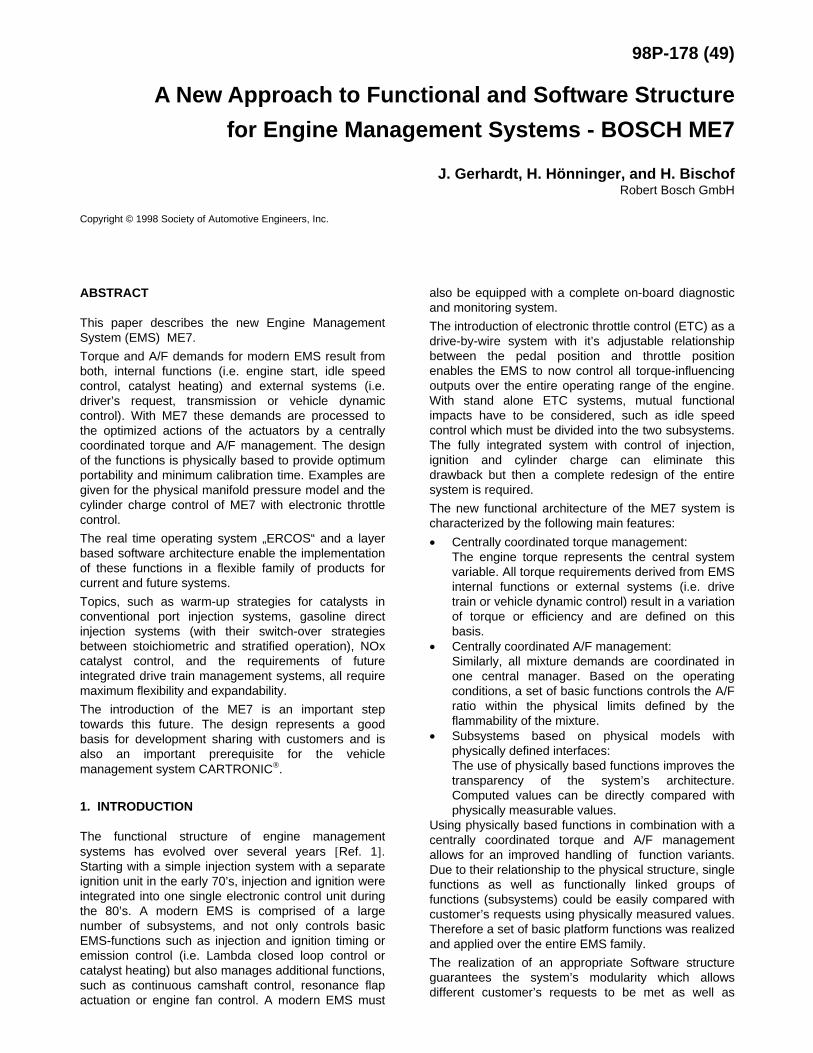
2.1.1 System Configuration
Figure 1 shows an ME7 system overview with the mainsensors and actuators. In addition to the componentsof a conventional EMS, the system is comprised of theETC related elements, which include the acceleratorpedal module to interpret the driver’s request, thethrottle actuator for cylinder charge control and thecruise control lever.
2.1.2 Brief Functional Overview
The ME7 contains all functions to control a modern SI-engine. In this section only a brief functional overview isgiven. Due to the system’s modularity very differentsystem configurations can be realized. For examplesystems with different sensors for cylinder chargedetermination (air mass or speed density), naturallyaspirated or turbocharged engines, engines with orwithout EGR and engines with variable camshaftactuation are possible. The main system features areas follows:
• The engine torque management which controls alltorque influencing actuators (see also section‘Functional Structure’).
• A/F ratio control with a central A/F manager, λ-pilotcontrol, λ-closed loop control, or alternatively with aNernst or universal λ-sensor and trim control(details see section ‘Functional Structure’).
• Sequential, cylinder individual fuel injection.• Ignition timing, including control of dwell angle and
ignition angle.• Cylinder individual knock control.• Emission control functions for optimized emissions
during cranking, start and after start which enablethe realization of different catalyst warm-upstrategies, using a lean mixture or a rich mixture
Figure 1: Engine Management System ME7
including exhaust gas recirculation (EGR) andsecondary air injection (SAI) control if necessary[Ref. 2], [Ref. 3].
• Canister purge control based on canister charge.• Idle speed control.• Diagnostic and monitoring functions:• The system is comprised of the complete OBD II
functionality to meet both MY ‘98 and future EOBDrequirements. A torque-based monitoring systemssupervises the throttle control under all operatingconditions and reacts with the appropriate limp-home functionality in case of a failure.
• To communicate with external systems, such as atransmission control system or a vehicle dynamiccontrol system, torque demands can be receivedvia a torque interface, realized via CAN. Thereforethe EMS is able to process external torquedemands within the torque manager. (see alsosection ‘Functional Structure’).
• Conventional or continuous camshaft control.• Resonance flap actuation.• Engine fan control.• Control of air-conditioner (A/C).• Cruise control.• The system contains the necessary interfaces to
application tools, end of line programming tools,service and SCAN-tools.
• Immobilizer.• Additional customer defined functions as required.
2.2 FUNCTIONAL STRUCTURE
Essential functional features of the ME7 structure arethe central torque and A/F management and the use ofphysically-based functions.
2.2.1 Torque-based system structure
2.2.1.1 Structural approach
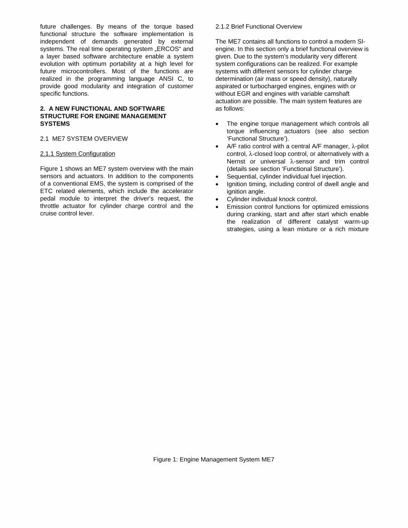
Choosing a torque-based system architecture wasinitiated by the followings concerns when the previoussituation was analyzed [Ref. 4], (Figure 2)
Figure 2: Influences on Engine Torque- previous situation
In the case of several torque or efficiency demands,
derived simultaneously from different subsystems,there was no central torque coordination. This meant,that subsystems inside the EMS as well as externalsystems directly required, for example, a reduction ofthe throttle or an ignition retard to obtain a certaintorque reduction. The priority of each demand had tobe defined independently in each subsystem. This lackof a central coordination caused interactions of differentdemands (due to shifts of operation points) resulting ina strong interdependence of calibration data of thedifferent subsystems (i.e. calibration of ignition timinginfluenced idle speed pilot control).
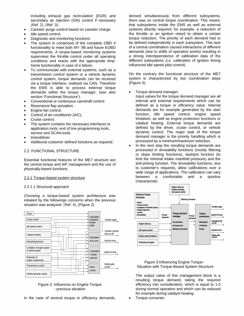
On the contrary the functional structure of the ME7system is characterized by two coordination steps(Figure 3).
• Torque demand manager: Input values for the torque demand manager are all
internal and external requirements which can bedefined as a torque or efficiency value. Internaldemands are for example generated by the startfunction, idle speed control, engine speedlimitation, as well as engine protection functions orcatalyst heating. External torque demands aredefined by the driver, cruise control, or vehicledynamic control. The major task of the torquedemand manager is the priority handling which isprocessed by a minimum/maximum selection.
• In the next step the resulting torque demands areprocessed in driveability functions (mostly filteringor slope limiting functions), dashpot function (tolimit the minimal intake manifold pressure) and theanti-jerking function. The driveability functions, dueto customer’s requests, allow calibrations over awide range of applications. The calibration can varybetween a comfortable and a sportivecharacteristic.
Figure 3:Influencing Engine Torque - Situation with Torque-Based System Structure
The output value of this management block is aresulting torque demand, taking the requiredefficiency into consideration, which is equal to 1.0during normal operation and which can be reducedfor example during catalyst heating.
• Torque converter:
Driver
Cruise control
Idle speed control
Catalyst heating
Anti-jerking function
Limitation of engine speed& vehicle speed
Protection ofengine components
Transmission control
Vehicle dynamic control
Waste-gatecontrolBoost
control
Calculation of spark advance
Calculationof inj. time
Calculation of desired throttle angle
Throttle angle
Cylinder individufuel cut-off
Injection time
Ignition timing
External TorqueDemands
• Driver• Cruise control• Limitation of vehicle speed• Vehicle dynamic control• Driveability
Engine start-up,Catalyst heating,Idle speed control
Efficiency demand
Torque demandmanager
Engine start-up
Idle speed control
Engine speed limitation
Protection of engine
Throttle angle
Ignition timing
Individual fuelcut-off
Injection time
Waste gatecontrol
Coordination
of torque and
efficiency demands
Realization
of desired
torque
Torqueconversion
Torquedemands
Torquedemand
In a second step the resulting torque demand isconverted into the available controller outputswhich are able to adjust the engine output torque.These controller outputs are the throttle angle,ignition timing and injection timing (including acylinder individual fuel cut-off) supplemented by awaste-gate control in the case of turbochargedengine.
This simple structure can be extended in case of highlydynamic torque demands resulting for example fromvehicle dynamic control. In this case two resultingtorque demands are defined:
• The long-term torque demand has to be realizedvia a variation of the cylinder charge. This demandresults in a variation of the throttle position and thewaste-gate opening, which means that it’s dynamicbehavior is limited for example by the regulatingspeed of the throttle actuator and the time constantof the intake manifold which can amount to several100 ms at low engine speeds.
• A separate short-term demand is realized via thecrank synchronous controller outputs (injection andignition timing) which enable a modification ofengine torque within the following combustion cycle.With the separate short-term component all highlydynamic torque demands, which only last some 100ms can be realized without affecting the slowcylinder charge path. Examples for highly dynamicdemands are the torque reduction generated in atransmission control for a comfortable gear shiftingor a quick and short demand when the vehicledynamic control is active.
2.2.1.2 Internal torque model
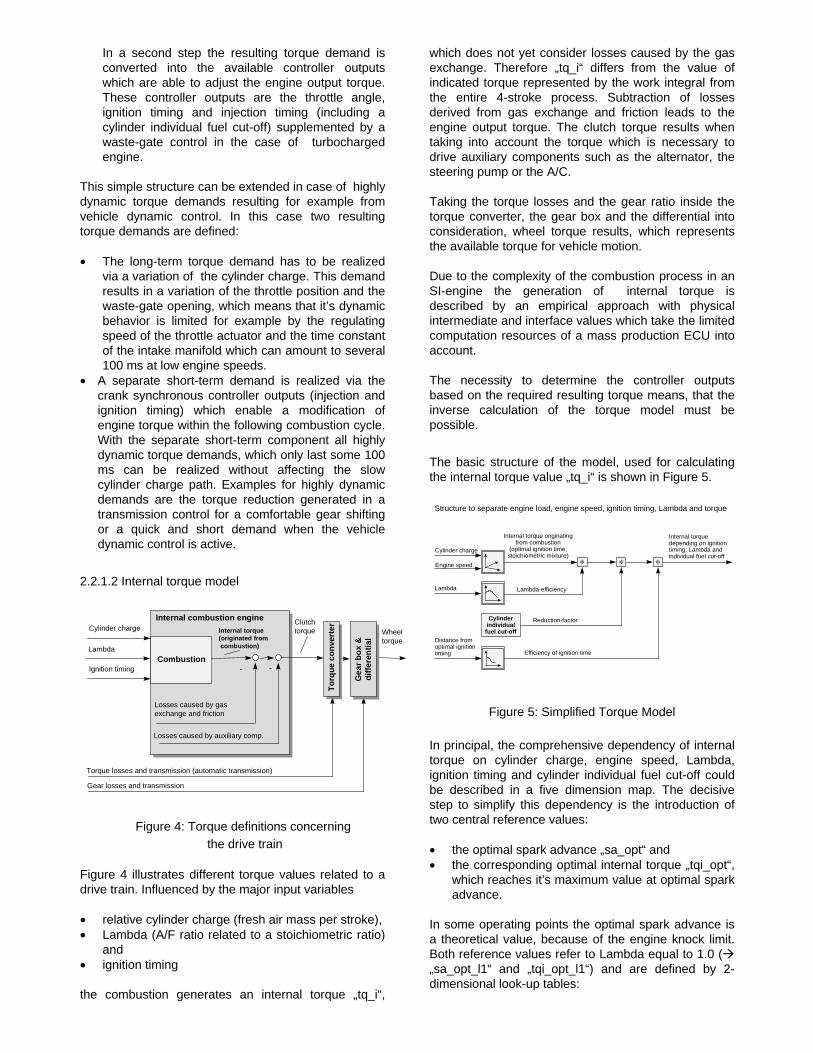
Figure 4: Torque definitions concerning the drive train
Figure 4 illustrates different torque values related to adrive train. Influenced by the major input variables
• relative cylinder charge (fresh air mass per stroke),• Lambda (A/F ratio related to a stoichiometric ratio)
and• ignition timing
the combustion generates an internal torque „tq_i“,
which does not yet consider losses caused by the gasexchange. Therefore „tq_i“ differs from the value ofindicated torque represented by the work integral fromthe entire 4-stroke process. Subtraction of lossesderived from gas exchange and friction leads to theengine output torque. The clutch torque results whentaking into account the torque which is necessary todrive auxiliary components such as the alternator, thesteering pump or the A/C.
Taking the torque losses and the gear ratio inside thetorque converter, the gear box and the differential intoconsideration, wheel torque results, which representsthe available torque for vehicle motion.
Due to the complexity of the combustion process in anSI-engine the generation of internal torque isdescribed by an empirical approach with physicalintermediate and interface values which take the limitedcomputation resources of a mass production ECU intoaccount.
The necessity to determine the controller outputsbased on the required resulting torque means, that theinverse calculation of the torque model must bepossible.
The basic structure of the model, used for calculatingthe internal torque value „tq_i“ is shown in Figure 5.
Figure 5: Simplified Torque Model
In principal, the comprehensive dependency of internaltorque on cylinder charge, engine speed, Lambda,ignition timing and cylinder individual fuel cut-off couldbe described in a five dimension map. The decisivestep to simplify this dependency is the introduction oftwo central reference values:
• the optimal spark advance „sa_opt“ and• the corresponding optimal internal torque „tqi_opt“,
which reaches it’s maximum value at optimal sparkadvance.
In some operating points the optimal spark advance isa theoretical value, because of the engine knock limit.Both reference values refer to Lambda equal to 1.0 (�„sa_opt_l1“ and „tqi_opt_l1“) and are defined by 2-dimensional look-up tables:
Combustion
Losses caused by gas exchange and friction
Losses caused by auxiliary comp.
Torque losses and transmission (automatic transmission)
Cylinder charge
Lambda
Ignition timing
Internal torque(originated from combustion)
Clutchtorque Wheel
torque
Gear losses and transmission
- -
Gea
r b
ox
&d
iffe
ren
tial
Gea
r b
ox
&d
iffe
ren
tial
Internal combustion engine
To
rqu
e co
nve
rter
∗
Cylinderindividualfuel cut-off
Engine speed
Internal torquedepending on ignitiontiming, Lambda andindividual fuel cut-off
Internal torque originatingfrom combustion
(optimal ignition time,stoichiometric mixture)
Cylinder charge
Distance fromoptimal ignitiontiming
Lambda
Structure to separate engine load, engine speed, ignition timing, Lambda and torque
∗∗
Lambda-efficiency
Reduction-factor
Efficiency of ignition time
sa_opt_l1 = fn. (rc, n_eng) (1)
tqi_opt_l1 = fn. (rc, n_eng) (2)
Relative cylinder air charge „rc“ refers to a 100% valuedefined by the displacement per cylinder and thestandard air density. The second influencing variable isthe engine speed „n_eng“.
The actual torque value „tqi“ is the result of amultiplication with Lambda- and spark advanceefficiencies
eff_lam = fn. (lam) (3)
eff_sa = fn. (d_sa) (4)
and the reduction factor „eff_red“ caused by a cylinderindividual fuel cut-off:
tqi =
tqi_opt_l1 * eff_lam * eff_red * eff_sa (5)
In equations 3 through 5 „lam“ represents Lambda. Forsimplification of the basic equation (equation 5), sparkadvance efficiency is defined depending on thedifference between actual spark advance „sa“ and theoptimal spark advance:
d_sa = sa_opt - sa (6)
2.2.1.3 Identification of model parameters
Equation (5) describes the decoupling of the five-dimensional relationship between the internal torqueand it’s influencing variables by introduction of theoptimal internal torque and the optimal spark advance.
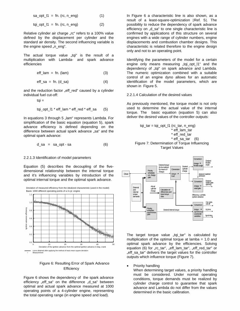
Figure 6 shows the dependency of the spark advanceefficiency „eff_sa“ on the difference „d_sa“ betweenoptimal and actual spark advance measured at 1000operating points of a 4-cylinder engine, representingthe total operating range (in engine speed and load).
In Figure 6 a characteristic line is also shown, as aresult of a least-square-optimization [Ref. 5]. Thepossibility to reduce the dependency of spark advanceefficiency on „d_sa“ to one single characteristic line isconfirmed by applications of this structure on severalengines with a wide range of cylinder numbers, enginedisplacements and combustion chamber designs. Thischaracteristic is related therefore to the engine designonly and not to an operating point.
Identifying the parameters of the model for a certainengine only means measuring „tqi_opt_l1“ and thedependency of „tqi“ on spark advance and Lambda.The numeric optimization combined with a suitablecontrol of an engine dyno allows for an automaticidentification of the model parameters, which areshown in Figure 5.
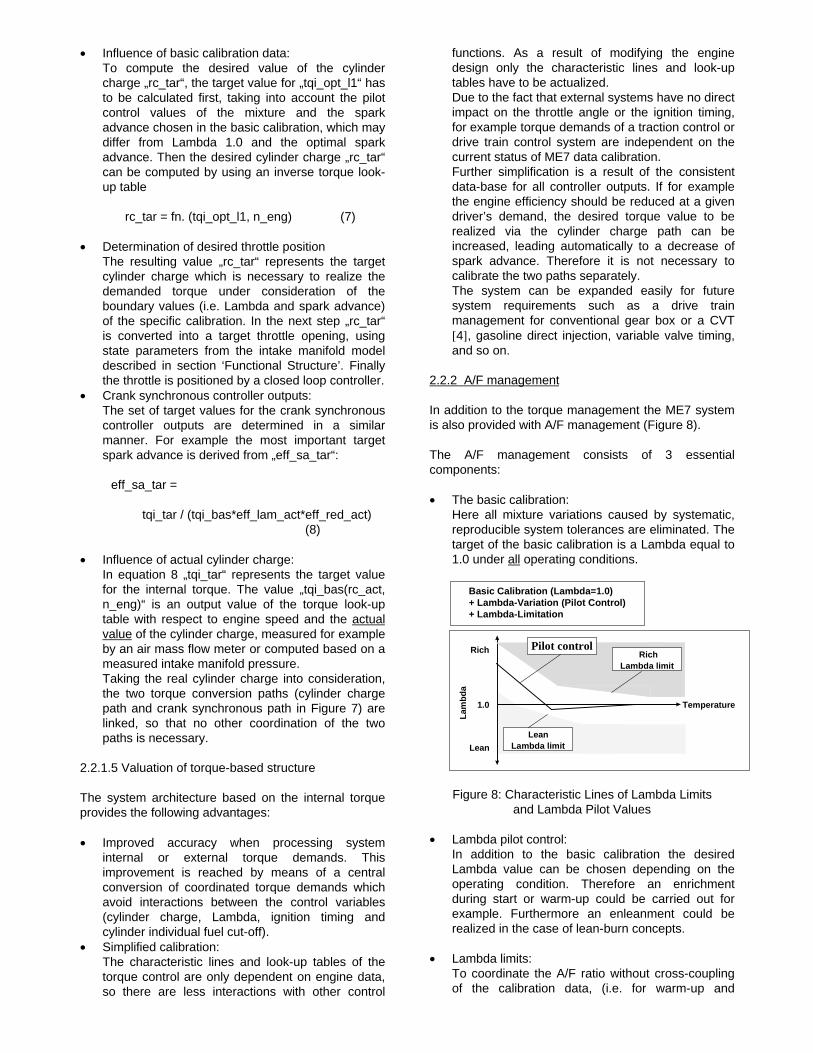
2.2.1.4 Calculation of the desired values
As previously mentioned, the torque model is not onlyused to determine the actual value of the internaltorque. The basic equation (equation 5) can alsodeliver the desired values of the controller outputs:
tqi_tar = tqi_opt_l1 (rc_tar, n_eng)* eff_lam_tar* eff_red_tar* eff_sa_tar (6)
Figure 7: Determination of Torque InfluencingTarget Values
The target torque value „tqi_tar“ is calculated bymultiplication of the optimal torque at lamba = 1.0 andoptimal spark advance by the efficiencies. Solvingequation (6) for „rc_tar“, „eff_lam_tar“, „eff_red_tar“ or„eff_sa_tar“ delivers the target values for the controlleroutputs which influence torque (Figure 7).
• Priority handling When determining target values, a priority handling
must be considered. Under normal operatingconditions, torque demands must be realized bycylinder charge control to guarantee that sparkadvance and Lambda do not differ from the valuesdetermined in the basic calibration.
Desired torque(to be realizedby means ofcharge)
Externalandinternaltorquedemands
desired manifoldpressure
Desiredwaste-gateopening
Desiredcylindercharge
Actualcylinder charge
Efficiency, Lambdaignition advance
Desired internal torque
Cyl.-indiv.cut-off
Inj.time
Ign.timing
Desiredthrottleangle
Conversion
torquesynchronouscrankshaftvariables
Driver
Conversion
chargethrottle angle
Conversion
chargewast-gate
Priorityscheduler,cyl. chargepath
Priorityscheduler,synchronouspath
Calculation ofefficiencies andbase torquedata
Conversion
torqueload
Figure 6: Resulting Error of Spark AdvanceEfficiency
0 10 20 30 40 50Deviation of the ignition advance from the optimal ignition advance in deg. crank
0.0
0.2
0.4
0.6
0.8
1.0
1.2
Igni
tion
adva
nce
effic
ienc
y
curve obtained after applying the method of least mean square deviationMeasurement
Deviation of measured efficiency from the idealized characteristic (used in the model)Basis: 1000 different operating points of a 4-cyl. engine
• Influence of basic calibration data: To compute the desired value of the cylinder
charge „rc_tar“, the target value for „tqi_opt_l1“ hasto be calculated first, taking into account the pilotcontrol values of the mixture and the sparkadvance chosen in the basic calibration, which maydiffer from Lambda 1.0 and the optimal sparkadvance. Then the desired cylinder charge „rc_tar“can be computed by using an inverse torque look-up table
rc_tar = fn. (tqi_opt_l1, n_eng) (7) • Determination of desired throttle position The resulting value „rc_tar“ represents the target
cylinder charge which is necessary to realize thedemanded torque under consideration of theboundary values (i.e. Lambda and spark advance)of the specific calibration. In the next step „rc_tar“is converted into a target throttle opening, usingstate parameters from the intake manifold modeldescribed in section ‘Functional Structure’. Finallythe throttle is positioned by a closed loop controller.
• Crank synchronous controller outputs: The set of target values for the crank synchronous
controller outputs are determined in a similarmanner. For example the most important targetspark advance is derived from „eff_sa_tar“:
eff_sa_tar =
tqi_tar / (tqi_bas*eff_lam_act*eff_red_act) (8)
• Influence of actual cylinder charge: In equation 8 „tqi_tar“ represents the target value
for the internal torque. The value „tqi_bas(rc_act,n_eng)“ is an output value of the torque look-uptable with respect to engine speed and the actual value of the cylinder charge, measured for example by an air mass flow meter or computed based on ameasured intake manifold pressure.
Taking the real cylinder charge into consideration,the two torque conversion paths (cylinder chargepath and crank synchronous path in Figure 7) arelinked, so that no other coordination of the twopaths is necessary.
2.2.1.5 Valuation of torque-based structure
The system architecture based on the internal torqueprovides the following advantages:
• Improved accuracy when processing systeminternal or external torque demands. Thisimprovement is reached by means of a centralconversion of coordinated torque demands whichavoid interactions between the control variables(cylinder charge, Lambda, ignition timing andcylinder individual fuel cut-off).
• Simplified calibration: The characteristic lines and look-up tables of the
torque control are only dependent on engine data,so there are less interactions with other control
functions. As a result of modifying the enginedesign only the characteristic lines and look-uptables have to be actualized.
Due to the fact that external systems have no directimpact on the throttle angle or the ignition timing,for example torque demands of a traction control ordrive train control system are independent on thecurrent status of ME7 data calibration.
Further simplification is a result of the consistentdata-base for all controller outputs. If for examplethe engine efficiency should be reduced at a givendriver’s demand, the desired torque value to berealized via the cylinder charge path can beincreased, leading automatically to a decrease ofspark advance. Therefore it is not necessary tocalibrate the two paths separately.
The system can be expanded easily for futuresystem requirements such as a drive trainmanagement for conventional gear box or a CVT[4], gasoline direct injection, variable valve timing,and so on.
2.2.2 A/F management
In addition to the torque management the ME7 systemis also provided with A/F management (Figure 8).
The A/F management consists of 3 essentialcomponents:
• The basic calibration: Here all mixture variations caused by systematic,
reproducible system tolerances are eliminated. Thetarget of the basic calibration is a Lambda equal to1.0 under all operating conditions.
Figure 8: Characteristic Lines of Lambda Limits
and Lambda Pilot Values
• Lambda pilot control: In addition to the basic calibration the desired
Lambda value can be chosen depending on theoperating condition. Therefore an enrichmentduring start or warm-up could be carried out forexample. Furthermore an enleanment could berealized in the case of lean-burn concepts.
• Lambda limits: To coordinate the A/F ratio without cross-coupling
of the calibration data, (i.e. for warm-up and
Pilot control
Lam
bd
a
Lean
Rich
1.0 Temperature
RichLambda limit
Lean Lambda limit
Basic Calibration (Lambda=1.0) + Lambda-Variation (Pilot Control) + Lambda-Limitation
catalyst heating) the range of Lambda variation islimited. The limit values are defined by themixture’s flammability dependent on the engineoperating point.
2.2.3 Physically based functions
Many platform functions in the ME7 are realized, basedon a physical model of the controlled system. The stepfrom heuristic functions to physically based functionsrequires a sufficient mathematical model of thecontrolled system. A major advantage of this concept isthe physical interpretation of internal and interfacevalues for improved comprehensibility andtransparency.
Because of the link to physical reality it is easier todefine platform functions and to reuse them in differentsystem configurations or future EMS generations.Using a set of platform functions also allows to transfera calibration data set from one project to another.
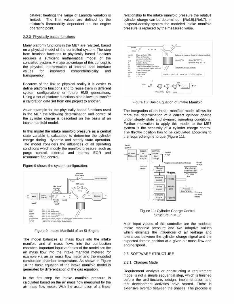
As an example for the physically based functions usedin the ME7 the following determination and control ofthe cylinder charge is described on the basis of anintake manifold model.
In this model the intake manifold pressure as a centralstate variable is calculated to determine the cylindercharge during dynamic and steady state operation.The model considers the influences of all operatingconditions which modify the manifold pressure, such aspurge control, external and internal EGR andresonance flap control.
Figure 9 shows the system configuration:
Figure 9: Intake Manifold of an SI-Engine
The model balances all mass flows into the intakemanifold and all mass flows into the combustionchamber. Important input variables of the model are theair mass flow into the intake manifold metered forexample via an air mass flow meter and the modeledcombustion chamber temperature. As shown in Figure10 the basic equation of the intake manifold model isgenerated by differentiation of the gas equation.
In the first step the intake manifold pressure iscalculated based on the air mass flow measured by theair mass flow meter. With the assumption of a linear
relationship to the intake manifold pressure the relativecylinder charge can be determined. [Ref.6],[Ref.7]. Ina speed-density system the modeled intake manifoldpressure is replaced by the measured value.
Figure 10: Basic Equation of Intake Manifold
The integration of an intake manifold model allows formore the determination of a correct cylinder chargeunder steady state and dynamic operating conditions.Further motivation to apply this model to the ME7system is the necessity of a cylinder charge control.The throttle position has to be calculated according tothe required engine torque (Figure 11).
Figure 11: Cylinder Charge ControlStructure in ME7
Main input values of this controller are the modeledintake manifold pressure and two adaptive valueswhich eliminate the influences of air leakage andtolerances between the cylinder charge signal and theexpected throttle position at a given air mass flow andengine speed .
2.3 SOFTWARE STRUCTURE
2.3.1 Changes Made
Requirement analysis or constructing a requirementmodel is not a simple sequential step, which is finishedbefore the architecture, design, implementation andtest development activities have started. There isextensive overlap between the phases. The process is
� � � � � � � �
� � � � � � � � � �
� � �� � � �� � � �
� � � � � � � � � �� � � � � � �
� � � � � � � �
� � � � � � � � � � � � � �
� � � � � � � � � � � � � � � � � � � � � �� � � � � � � � � � � � � � � � � � � � � � � � � � � � � � �� � � � � � � � � � � � � � � � � � � � � � � � � � � � � � � � �� � � � � � � � � � � � � � � � � � � � � � � � � � � � � � � � � � � �� � � � � � � � � � � � � � � � � � � � � � � � � � �� � � � � � � � � � � � � � � � � � � � � � � � � � � � � � � � � � � � � � � � � � � � � � � � � � � � � � � � � � � � � � � � � � � � ! � � � � � � � � �� � � � � � � � � � � � " � � � � � � � � � � � � � � � � � � � � � � � � � � � � � � � � � � � �# � � � � # � � � � " � � � � � � � � � � � � � � � � � � � � � � � � � � � � � � � � � � � � � � � � �
� � � � � � �! � � �
� � � � �
� � � � � �
� � � �
� � � �
� � � � �� � � �
� � � � �
� �� �
� �� �
� � �� � �
� �# � � # �
� � �
� � � � �
� � � � � � � � � � � � � � � � � $ � � � %� � � � � � � � � � � � � � � � � �� � � � � � � � � � � � � � � � � � � � � � � & � � � � � � � ' � � � � � � � � � � � � � � � � � � � � �� � � � ( � � � � � � � � � � � � � � � � � � � �# � � � " � � � � � � � � � � � � � � � � � � � � � � � � � � � �" � � � ) � � � � � � � � � � � � � � � � � � � � � � � � � �# � � � " � � � � � � � � � � � � � � � �� � � � � � � � � � � � � � � � �& * � � + � , * , - � � & �" * � � + � . / - � 0
� � � � � � � � � � � � � � � � � � � � � � � � � � � � � � � � � � � � � � �
$ � � � 1 � � % 2 # � � + � $ � � � 1 � � % � 2 � � � 2 � " �� � � + � $ � � � � � 3 � � % � 2 � � � 2 � " �
4 � � � � � � � � � � � � � � � ' � � � � � � �
� � � � � # � � � � " �
� �$ � � � %
$ � %
� � � 1 � � � � � � � � $ � � � � 3 � � % � 2 � � � � � � 2 � � * � 2 � $ " � 1 " * % � 2 � $ # � 1 # � %
� � �
"
�
"
& * 2 $ # � 1 # � % " � 1 " *
"
� � � �
� �
� � �� �
Desiredtorque Cyl. charge
determination
Air massflow
Adaptation results (offset/ factor)
Pedalposition
Driver’s Request
Calcul.of
desiredtorque
Pressure upstream throttle
Wastegate
Wastegate
Desiredcharge
Convers.torque
into charge
Boostcontrol
Position control
Chargecontrol
Convers.torque
-> ignition
Throttle
Ignition
EngineEngine
Pressuredetermination
Actualcharge
iterative, both within each phase and over multiplephases. This is especially true for a platformdevelopment, supporting a complete product familywith a broad variance in system and customer specificconfigurations.
Systems evolve in time. Building a new system fromscratch is not the typical approach, due to restrictions indevelopment time and effort. The ME7 was built froman existing system in an incremental and evolutionarymanner, thus being able to deliver a running system fortest and calibration purposes right from the beginning.
The maintenance or reengineering phase thereforedoes not begin with the delivery and it does not endwith delivery and mass production. The maintenancephase is in fact the most important phase to proveexpansion capability, reuse and variants engineering.
Hard facts are the ever increasing complexity,changing functional requirements and continuouslytightened nonfunctional requirements related to quality,cost and time to market.
Development systems have to handle these real worldaspects to immediately improve the situation. In theME7 development therefore a selected set of changeswas planned and introduced step by step. This processis still ongoing.
There are bottom up forced changes. The use of highlevel programming languages, ANSI C instead ofAssembler in the ME7, is one example. There is nosensible way to handle Assembler programs of suchcomplexity. The systematic introduction of specificationsimulation and code inspection methods are furtherexamples for this class of changes, which wereabsolutely necessary.
Changes with "top down character" in the project werethe development of a new functional structure and of asoftware architecture to support their implementation ina product line.
2.3.2 Context
What is the system we are talking about? Traditionallywe find a dedicated electronic control unit (ECU) forengine management, connected to a lot of sensors,actuators and other control units or monitoring devicesin the car. The system consists of the ECU itself andall the devices it is connected to. Proceeding in anincremental and evolutionary way the context diagramis drawn by replacing the ECU with the singletransformation "control & monitor engine" and thedevices connected to it are the terminators. In the ME7project this partitioning was a given fact. (The contextdiagram partitions the information and processes thatare within the scope of the system and those that areoutside the scope)
The ECU has one or two standard microcontrollers andperipheral electronics functionally comparable to formersystems. The peripheral electronics are more highly
integrated. The mechanical design of the ECU is alsonew, supporting surface mounting of all electronicdevices. Furthermore variants in microhybridtechnology are available, which offer new options inmechanical system integration. Yet the partitioningbetween hardware and software was not underconsideration in the project. Being aware of the manychanges in the development process, functionalstructure and software was a conscious decision forrisk management.
There are various possible system configurations withmore than a hundred input and output flows, howeverall have in principle the same topology and a lot ofcommonalties. Measuring engine speed and load areexamples for commonalties on an abstract levelbetween all system variants.
Most important for a given system variant a staticenvironment can be assumed, therefore a deterministicsystem approach was chosen.
2.3.3 Architecture
In the architectural development the question how todesign has to be answered. The functionalrequirements at one level must be rigorously allocatedto a physical structure with nonfunctional requirementsadded.
2.3.4 Software architecture
Following strategies for real time system specificationas described, for example, by Hatley and Pirbhai [Ref.11] or Goldsmith [Ref. 12] and using the principles ofabstraction and decomposition, the technologyindependent requirements model has to betransformed in a technology-nonspecific physicalmodel. Therefore buffers are inserted between theessential requirements model core and theenvironment. The resulting architecture templateembeds the requirements model core into inputprocessing and output processing architecture blocks.Also blocks for interface-processing and self-test areadded as shown in Figure 12.
Self-Test,... processing
Interface,...processing
Output processingInput processing
Requirements Core
Information
Control
Transformation
Figure 12: Architecture Template
The essential requirements model describes what thelogical outputs should be, depending on the logicalinputs. It assumes ideal technology, though all the inputflows are in parallel and instantly transformed into thecorresponding output flows. The input and outputprocessing blocks have to convert the physical flows
into the logical flows described by the requirementscore model. This model has to be enhanced by thetiming requirements. For all the logical flows responsetimes or actualization rates, the resolution, accuracyand value ranges must be specified.
The further decomposition into architecture modules,architecture flows and so on, ending in codeorganization charts is a sophisticated process.Important guidelines for partitioning are the generalprinciples of cohesion and coupling, as known fromstructural analysis and design methods. This is alsovalid for object based or other methods and languagesfor real time system description and construction.Independent from the methods used, this is anexample of the already mentioned inherent iterativeand recursive character of complex systemsdevelopment.
The intention here was to minimize the influence of theµC and the various configurations, using differentsensors and actuators on the design andimplementation of the requirements core block. Therequirements model represents the knowledge aboutthe application work and should be reused even on theimplementation level for the whole product family andalso for further generations of engine managementsystems. A set of rules for architecture, design andimplementation is necessary to encapsulate the µC andsystem configuration dependencies.
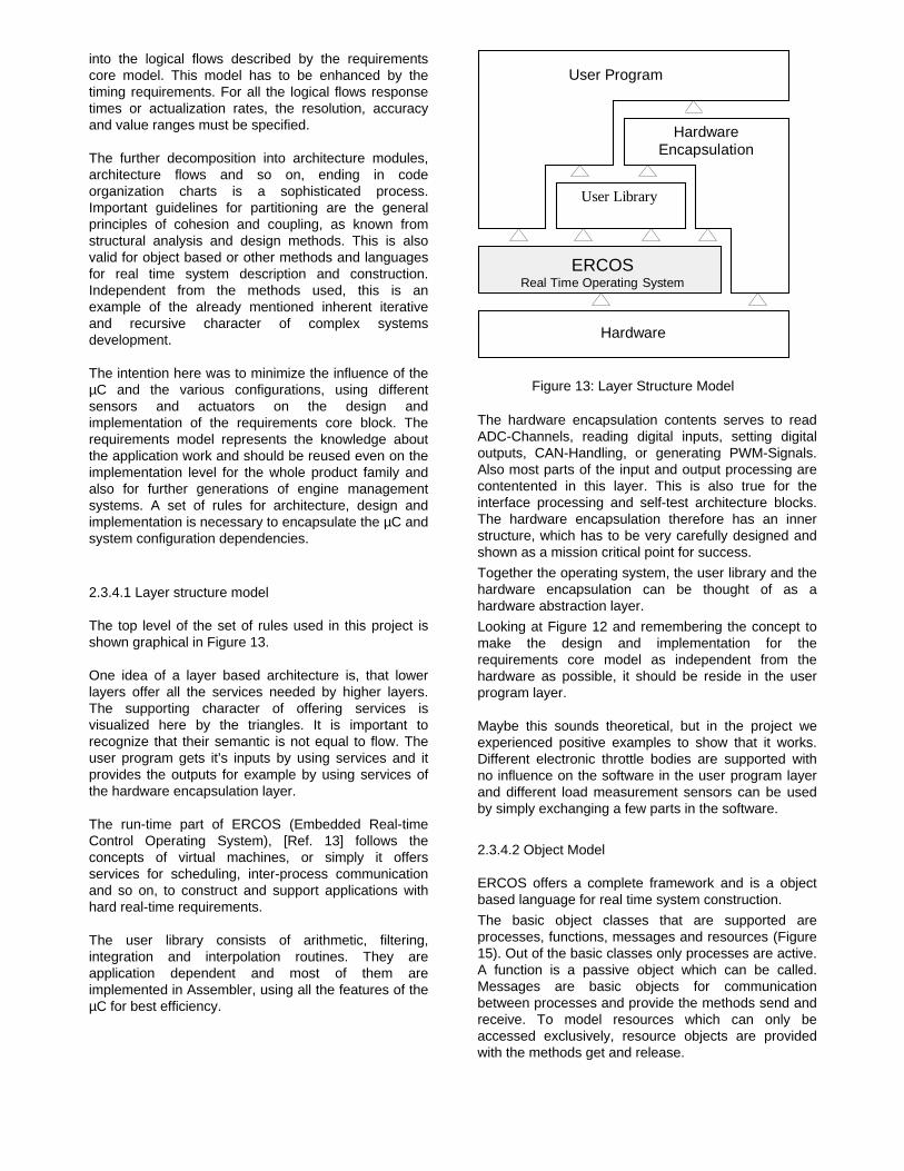
2.3.4.1 Layer structure model
The top level of the set of rules used in this project isshown graphical in Figure 13.
One idea of a layer based architecture is, that lowerlayers offer all the services needed by higher layers.The supporting character of offering services isvisualized here by the triangles. It is important torecognize that their semantic is not equal to flow. Theuser program gets it’s inputs by using services and itprovides the outputs for example by using services ofthe hardware encapsulation layer.
The run-time part of ERCOS (Embedded Real-timeControl Operating System), [Ref. 13] follows theconcepts of virtual machines, or simply it offersservices for scheduling, inter-process communicationand so on, to construct and support applications withhard real-time requirements.
The user library consists of arithmetic, filtering,integration and interpolation routines. They areapplication dependent and most of them areimplemented in Assembler, using all the features of theµC for best efficiency.
Hardware
ERCOSReal Time Operating System
HardwareEncapsulation
User Program
User Library
Figure 13: Layer Structure Model
The hardware encapsulation contents serves to readADC-Channels, reading digital inputs, setting digitaloutputs, CAN-Handling, or generating PWM-Signals.Also most parts of the input and output processing arecontentented in this layer. This is also true for theinterface processing and self-test architecture blocks.The hardware encapsulation therefore has an innerstructure, which has to be very carefully designed andshown as a mission critical point for success.
Together the operating system, the user library and thehardware encapsulation can be thought of as ahardware abstraction layer.
Looking at Figure 12 and remembering the concept tomake the design and implementation for therequirements core model as independent from thehardware as possible, it should be reside in the userprogram layer.
Maybe this sounds theoretical, but in the project weexperienced positive examples to show that it works.Different electronic throttle bodies are supported withno influence on the software in the user program layerand different load measurement sensors can be usedby simply exchanging a few parts in the software.
2.3.4.2 Object Model
ERCOS offers a complete framework and is a objectbased language for real time system construction.
The basic object classes that are supported areprocesses, functions, messages and resources (Figure15). Out of the basic classes only processes are active.A function is a passive object which can be called.Messages are basic objects for communicationbetween processes and provide the methods send andreceive. To model resources which can only beaccessed exclusively, resource objects are providedwith the methods get and release.
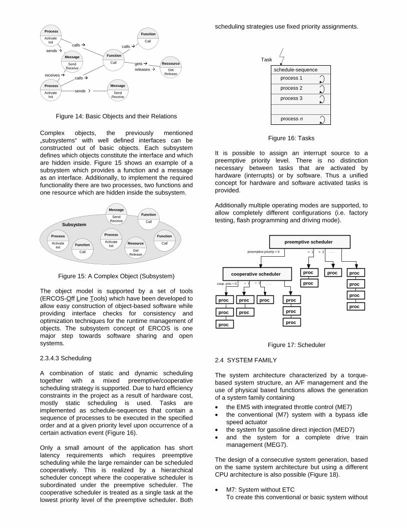
Figure 14: Basic Objects and their Relations
Complex objects, the previously mentioned„subsystems“ with well defined interfaces can beconstructed out of basic objects. Each subsystemdefines which objects constitute the interface and whichare hidden inside. Figure 15 shows an example of asubsystem which provides a function and a messageas an interface. Additionally, to implement the requiredfunctionality there are two processes, two functions andone resource which are hidden inside the subsystem.
GetRelease
Resource
Process
ActivateInit
Process
ActivateInit
Call
Function
Call
Function
Call
Function
Message
SendReceive
Subsystem
Figure 15: A Complex Object (Subsystem)
The object model is supported by a set of tools(ERCOS-Off L ine T ools) which have been developed to allow easy construction of object-based software whileproviding interface checks for consistency andoptimization techniques for the runtime management ofobjects. The subsystem concept of ERCOS is onemajor step towards software sharing and opensystems.
2.3.4.3 Scheduling
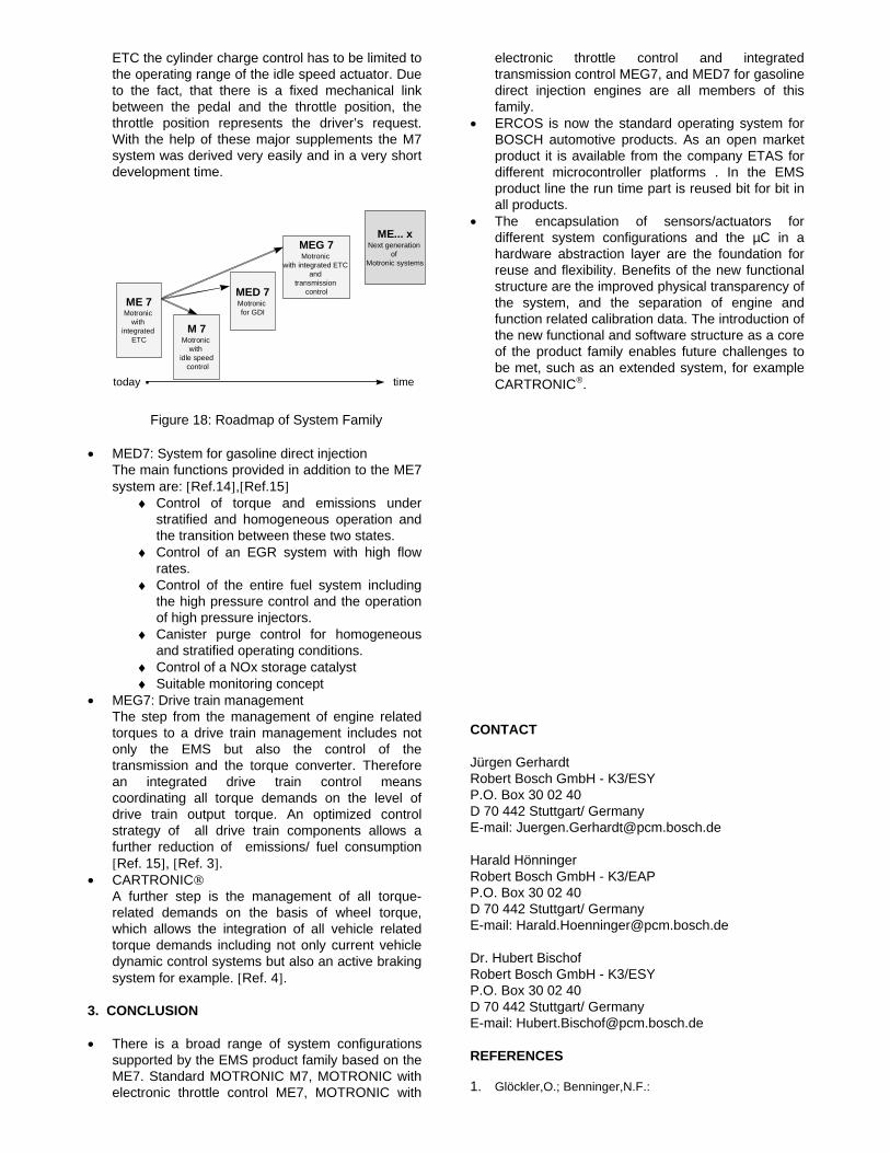
A combination of static and dynamic schedulingtogether with a mixed preemptive/cooperativescheduling strategy is supported. Due to hard efficiencyconstraints in the project as a result of hardware cost,mostly static scheduling is used. Tasks areimplemented as schedule-sequences that contain asequence of processes to be executed in the specifiedorder and at a given priority level upon occurrence of acertain activation event (Figure 16).
Only a small amount of the application has shortlatency requirements which requires preemptivescheduling while the large remainder can be scheduledcooperatively. This is realized by a hierarchicalscheduler concept where the cooperative scheduler issubordinated under the preemptive scheduler. Thecooperative scheduler is treated as a single task at thelowest priority level of the preemptive scheduler. Both
scheduling strategies use fixed priority assignments.
Figure 16: Tasks
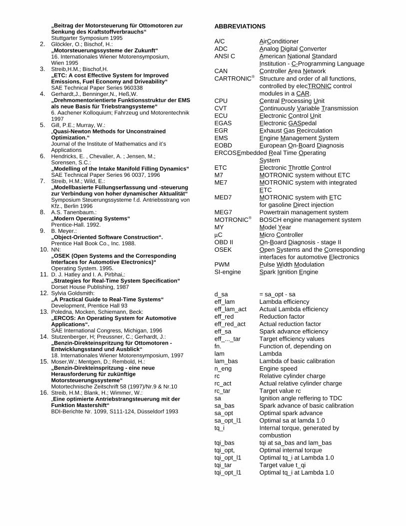
It is possible to assign an interrupt source to apreemptive priority level. There is no distinctionnecessary between tasks that are activated byhardware (interrupts) or by software. Thus a unifiedconcept for hardware and software activated tasks isprovided.
Additionally multiple operating modes are supported, toallow completely different configurations (i.e. factorytesting, flash programming and driving mode).
Figure 17: Scheduler
2.4 SYSTEM FAMILY
The system architecture characterized by a torque-based system structure, an A/F management and theuse of physical based functions allows the generationof a system family containing
• the EMS with integrated throttle control (ME7)• the conventional (M7) system with a bypass idle
speed actuator• the system for gasoline direct injection (MED7)• and the system for a complete drive train
management (MEG7).
The design of a consecutive system generation, basedon the same system architecture but using a differentCPU architecture is also possible (Figure 18).
• M7: System without ETC To create this conventional or basic system without
Message
SendReceive
Process
ActivateInit
GetRelease
Ressource
Call
Function
Process
ActivateInit
Call
FunctionMessage
SendReceive releases Å
gets Å
sends Å
receives Å
sends Åcalls Å calls Å
calls Å
schedule-sequence
Task
process 1
process 2
process 3
process n
preemptive scheduler
cooperative scheduler
proc procproc proc
preemptive priority = 0
coop. prio = 0 = 1
procproc proc
= 1 . . . = 2
= 2 . . . proc
proc
proc
proc proc
proc
proc
proc
proc
ETC the cylinder charge control has to be limited tothe operating range of the idle speed actuator. Dueto the fact, that there is a fixed mechanical linkbetween the pedal and the throttle position, thethrottle position represents the driver’s request.With the help of these major supplements the M7system was derived very easily and in a very shortdevelopment time.
Figure 18: Roadmap of System Family
• MED7: System for gasoline direct injection The main functions provided in addition to the ME7
system are: [Ref.14],[Ref.15]♦ Control of torque and emissions under
stratified and homogeneous operation andthe transition between these two states.
♦ Control of an EGR system with high flowrates.
♦ Control of the entire fuel system includingthe high pressure control and the operationof high pressure injectors.
♦ Canister purge control for homogeneousand stratified operating conditions.
♦ Control of a NOx storage catalyst♦ Suitable monitoring concept
• MEG7: Drive train management The step from the management of engine related
torques to a drive train management includes notonly the EMS but also the control of thetransmission and the torque converter. Thereforean integrated drive train control meanscoordinating all torque demands on the level ofdrive train output torque. An optimized controlstrategy of all drive train components allows afurther reduction of emissions/ fuel consumption[Ref. 15], [Ref. 3].
• CARTRONIC A further step is the management of all torque-
related demands on the basis of wheel torque,which allows the integration of all vehicle relatedtorque demands including not only current vehicledynamic control systems but also an active brakingsystem for example. [Ref. 4].
3. CONCLUSION
• There is a broad range of system configurationssupported by the EMS product family based on theME7. Standard MOTRONIC M7, MOTRONIC withelectronic throttle control ME7, MOTRONIC with
electronic throttle control and integratedtransmission control MEG7, and MED7 for gasolinedirect injection engines are all members of thisfamily.
• ERCOS is now the standard operating system forBOSCH automotive products. As an open marketproduct it is available from the company ETAS fordifferent microcontroller platforms . In the EMSproduct line the run time part is reused bit for bit inall products.
• The encapsulation of sensors/actuators fordifferent system configurations and the µC in ahardware abstraction layer are the foundation forreuse and flexibility. Benefits of the new functionalstructure are the improved physical transparency ofthe system, and the separation of engine andfunction related calibration data. The introduction ofthe new functional and software structure as a coreof the product family enables future challenges tobe met, such as an extended system, for exampleCARTRONIC.
CONTACT
Jürgen GerhardtRobert Bosch GmbH - K3/ESYP.O. Box 30 02 40D 70 442 Stuttgart/ GermanyE-mail: [email protected]
Harald HönningerRobert Bosch GmbH - K3/EAPP.O. Box 30 02 40D 70 442 Stuttgart/ GermanyE-mail: [email protected]
Dr. Hubert BischofRobert Bosch GmbH - K3/ESYP.O. Box 30 02 40D 70 442 Stuttgart/ GermanyE-mail: [email protected]
REFERENCES
1. Glöckler,O.; Benninger,N.F.:
time
ME 7Motronic
with integrated
ETCM 7
Motronic with
idle speed control
MED 7Motronic for GDI
MEG 7Motronic
with integrated ETC and
transmission control
ME... xNext generation
of Motronic systems
today
„Beitrag der Motorsteuerung für Ottomotoren zur Senkung des Kraftstoffverbrauchs“ Stuttgarter Symposium 19952. Glöckler, O.; Bischof, H.:
„Motorsteuerungssysteme der Zukunft“16. Internationales Wiener Motorensymposium,Wien 1995
3. Streib,H.M.; Bischof,H.„ETC: A cost Effective System for ImprovedEmissions, Fuel Economy and Driveability“SAE Technical Paper Series 960338
4. Gerhardt,J., Benninger,N., Heß,W.„Drehmomentorientierte Funktionsstruktur der EMSals neue Basis für Triebstrangsysteme“
6. Aachener Kolloquium; Fahrzeug und Motorentechnik1997
5. Gill, P.E.; Murray, W.:„Quasi-Newton Methods for UnconstrainedOptimization.“Journal of the Institute of Mathematics and it’sApplications
6. Hendricks, E. , Chevalier, A. ; Jensen, M.;Sorensen, S.C.:„Modelling of the Intake Manifold Filling Dynamics“SAE Technical Paper Series 96 0037, 1996
7. Streib, H.M.; Wild, E.:„Modellbasierte Füllungserfassung und -steuerungzur Verbindung von hoher dynamischer Aktualität“Symposium Steuerungssysteme f.d. Antriebsstrang vonKfz., Berlin 1996
8. A.S. Tanenbaum.:„Modern Operating Systems“Prentice-Hall. 1992.
9. B. Meyer.:„Object-Oriented Software Construction“.Prentice Hall Book Co., Inc. 1988.
10. NN: „OSEK (Open Systems and the Corresponding
Interfaces for Automotive Electronics)“Operating System. 1995.
11. D. J. Hatley and I. A. Pirbhai,:„Strategies for Real-Time System Specification“Dorset House Publishing, 1987
12. Sylvia Goldsmith:„A Practical Guide to Real-Time Systems“Development, Prentice Hall 93
13. Poledna, Mocken, Schiemann, Beck:„ERCOS: An Operating System for AutomotiveApplications“.SAE International Congress, Michigan, 1996
14. Stutzenberger, H; Preussner, C.; Gerhardt, J.:„Benzin-Direkteinspritzung für Ottomotoren -Entwicklungsstand und Ausblick“18. Internationales Wiener Motorensymposium, 1997
15. Moser,W.; Mentgen, D.; Rembold, H.: „Benzin-Direkteinspritzung - eine neue
Herausforderung für zukünftigeMotorsteuerungssysteme“
Motortechnische Zeitschrift 58 (1997)/Nr.9 & Nr.1016. Streib, H.M.; Blank, H.; Wimmer, W.:
„Eine optimierte Antriebstrangsteuerung mit derFunktion Mastershift“BDI-Berichte Nr. 1099, S111-124, Düsseldorf 1993
ABBREVIATIONS
A/C AirC onditioner ADC Analog D igital C onverter ANSI C American N ational S tandard
Institution - C- Programming Language CAN Controller A rea N etwork CARTRONIC Structure and order of all functions,
controlled by elecTRONIC control modules in a CAR.
CPU Central P rocessing U nit CVT Continuously V ariable T ransmission ECU Electronic C ontrol U nit EGAS Electronic GAS pedal EGR Exhaust G as R ecirculation EMS Engine M anagement S ystem EOBD European O n-B oard D iagnosis ERCOSEmbedded R eal Time O perating
System ETC Electronic T hrottle C ontrol M7 MOTRONIC system without ETC ME7 MOTRONIC system with integrated
ETC MED7 MOTRONIC system with E TC
for gasoline Direct injection MEG7 Powertrain management systemMOTRONIC BOSCH engine management systemMY Model Y ear µC Micro C ontroller OBD II On-B oard D iagnosis - stage II OSEK Open S ystems and the C orresponding
interfaces for automotive Electronics PWM Pulse W idth M odulation SI-engine Spark I gnition E ngine
d_sa = sa_opt - saeff_lam Lambda efficiencyeff_lam_act Actual Lambda efficiencyeff_red Reduction factoreff_red_act Actual reduction factoreff_sa Spark advance efficiencyeff_..._tar Target efficiency valuesfn. Function of, depending onlam Lambdalam_bas Lambda of basic calibrationn_eng Engine speedrc Relative cylinder chargerc_act Actual relative cylinder chargerc_tar Target value rcsa Ignition angle reffering to TDCsa_bas Spark advance of basic calibrationsa_opt Optimal spark advancesa_opt_l1 Optimal sa at lamda 1.0tq_i Internal torque, generated by
combustiontqi_bas tqi at sa_bas and lam_bastqi_opt, Optimal internal torquetqi_opt_l1 Optimal tq_i at Lambda 1.0tqi_tar Target value t_qitqi_opt_l1 Optimal tq_i at Lambda 1.0


![INJECTION - MX17 - spc960.com · bosch mono-motronic ma 1.7 (single-point) x x x alfa romeo 155 2.0 [ts 2] - 155 2.0 ... bosch motronic m 1.7 (multi-point) x x x start with code card](https://img.pdfslide.us/doc/110x75/5aebc4857f8b9a36698ec479/injection-mx17-mono-motronic-ma-17-single-point-x-x-x-alfa-romeo-155-20.jpg)


![CAR 58 IDC4w Software Update - CAR 58 CAR ENVIRONMENT ABARTH • Bosch Motronic ME 17.3.0 CF6 petrol injection AUDI • Bosch 9.0i PQ26 ABS/ESP [ /14>] • Bosch 9.0i ABS/EDS/ASR/ESP](https://img.pdfslide.us/doc/110x75/60b51d01f26b4b1a1a5834a3/car-58-idc4w-software-update-car-58-car-environment-abarth-a-bosch-motronic.jpg)