Embed Size (px)
DESCRIPTION
Basic topics for Bosch Motronic
Citation preview
6/10/2014 Bosch Motronic Basic Motronic 1.1 1.2 1.3 Fuel Injection Technical Article
http://www.hiperformancestore.com/motronic.htm 1/60
Bosch Motronic Basic, Motronic 1.1, Motronic 1.2, andMotronic 1.3 Fuel Injection Tech Article
The technical/repair portion of this article is essentiallyfinished. I will still add to it and update it from time to time.Introduction:
This article is intended to help owners of cars with Bosch Motronic Fuel injection perform their ownservice. The article is based on the Original Bosch Motronic system used on the 1987 E28 BMW 535i.
While this article is primarily intended as a fuel injection article, it will include testing information forsome components of the ignition and other systems related to the Motronic system. This is becausethe Motronic system ties into a lot of things, ignition, emission, even the 535i's automatic cabintemperature control. Everything it ties into will be covered.
You will not need any Bosch or BMW testing equipment, this article should allow you to test andtroubleshoot with just basic tools and an inexpensive multi meter.
Disclaimer: I have no factory training. Use this information at your own risk. I strongly suggesthaving a fire extinguisher nearby whenever working on an automotive fuel system. As a matter of fact,just stop reading this right now and go buy a factory BMW shop manual.
How to use this article:
You can use this article in a few ways, first you could follow it through step by step. This would verythoroughly check out your fuel injection and ignitions systems. I recommend this method if you haveplenty of time, if your car has more than one problem, or if you just purchased the car and want to getit running just right. If your car has one simple problem you can use this article as a sort of troubleshooting and testing guide for specific components. To make trouble shooting easier I have includedthe symptoms associated with a defect for each part of the injection system. The sections showing
these symptoms can be found quickly by looking for the *Symbol. As a general rule the componentsthat can cause the most problems and/or the biggest problems are towards the beginning of thisarticle. For example, air leaks in the vacuum hoses, lack of power to the fuel injection system, fuelpressure and fuel injectors can all cause a variety of problems, and even prevent the car from running.A faulty idle air control valve will only cause problems at idle so it's covered later in the article.
6/10/2014 Bosch Motronic Basic Motronic 1.1 1.2 1.3 Fuel Injection Technical Article
http://www.hiperformancestore.com/motronic.htm 2/60
What cars does this article cover?
The article specifically covers the E28 535i. It also covers most of the changes associated with theS38 engine in the E28 BMW M5, the E34 BMW M5 and the BMW E24 M6.
Can this article help me with other cars?
YES! The short verison is this. If you car has Bosch Motronic AND has a distributor, it’s versionthat’s covered in this article.
With a few minor variations the same Motronic system is used on many other BMWs from the 1980'sincluding the BMW 533i, 633i, 733i, 635i, 735i, 528e (Note: some early 533, 633, 733 BMWs useBosch L-Jetronic. Please refer to my L-Jetronic tech articles for those cars.) Various BMW E30s, thethe 325i and 325e use Motronic, however they are set up differently. Most of the component tests inthis article are relevant for the Motronic E30s, however the locations of the components will usually bedifferent. I will try to point out the variations in these cars within this article, but there is no way I cannail every variation.
There were many other cars built in the 80's and early 90's using this same basic fuel injection andignition system including the Alfa Romeo 164, Rolls Royce Silver Spur, and others. The Japanese builtclones of this system under license and many Japanese cars from the 90's use this system.
Some BMW 635 cars use the Motronic 1.3 system. It's essentially the same as the 1.1 system. Insome cases, it still uses the cold start valve/injector, unlike the 1.1 system in the 528e. The big changein the 1.3 system was its ability to store more fault codes, and keep them in memory when the car isshut off. To allow it to do this, the 1.3's ECU (electronic control unit, which is the "Motronic ControlUnit", or fuel injection and ignition computer) is hard wired to the battery, so it always has voltage if thebattery is charged and connected.
Motronic 1.2 is essentially just like 1.1 with the addition of a hot wire air flow sensor replacing theolder flapper type. The BMW E34 M5 uses 1.2 with addition of a plenum divider and an air pump, bothof which are covered in the article.
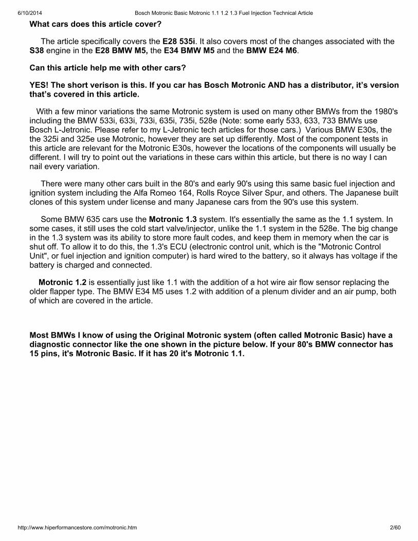
Most BMWs I know of using the Original Motronic system (often called Motronic Basic) have adiagnostic connector like the one shown in the picture below. If your 80's BMW connector has15 pins, it's Motronic Basic. If it has 20 it's Motronic 1.1.
6/10/2014 Bosch Motronic Basic Motronic 1.1 1.2 1.3 Fuel Injection Technical Article
http://www.hiperformancestore.com/motronic.htm 3/60
As far as I know all E28 BMW 535i cars use Motronic Basic. The only E28 I know of that usedMotronic 1.1 was the later BMW 528e (build dates from 3-1987 and on). Except where noted, all textand pictures in this article are from Motronic Basic. I will try to cover the 1.1 system in this article, but Idon't have a 1.1 car here to take pictures of.
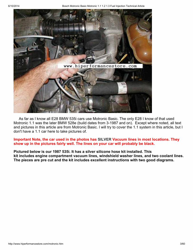
Important Note, the car used in the photos has SILVER Vacuum lines in most locations. Theyshow up in the pictures fairly well. The lines on your car will probably be black.
Pictured below is our 1987 535i. It has a silver silicone hose kit installed. Thiskit includes engine compartment vacuum lines, windshield washer lines, and two coolant lines.The pieces are pre cut and the kit includes excellent instructions with two good diagrams.
6/10/2014 Bosch Motronic Basic Motronic 1.1 1.2 1.3 Fuel Injection Technical Article
http://www.hiperformancestore.com/motronic.htm 4/60
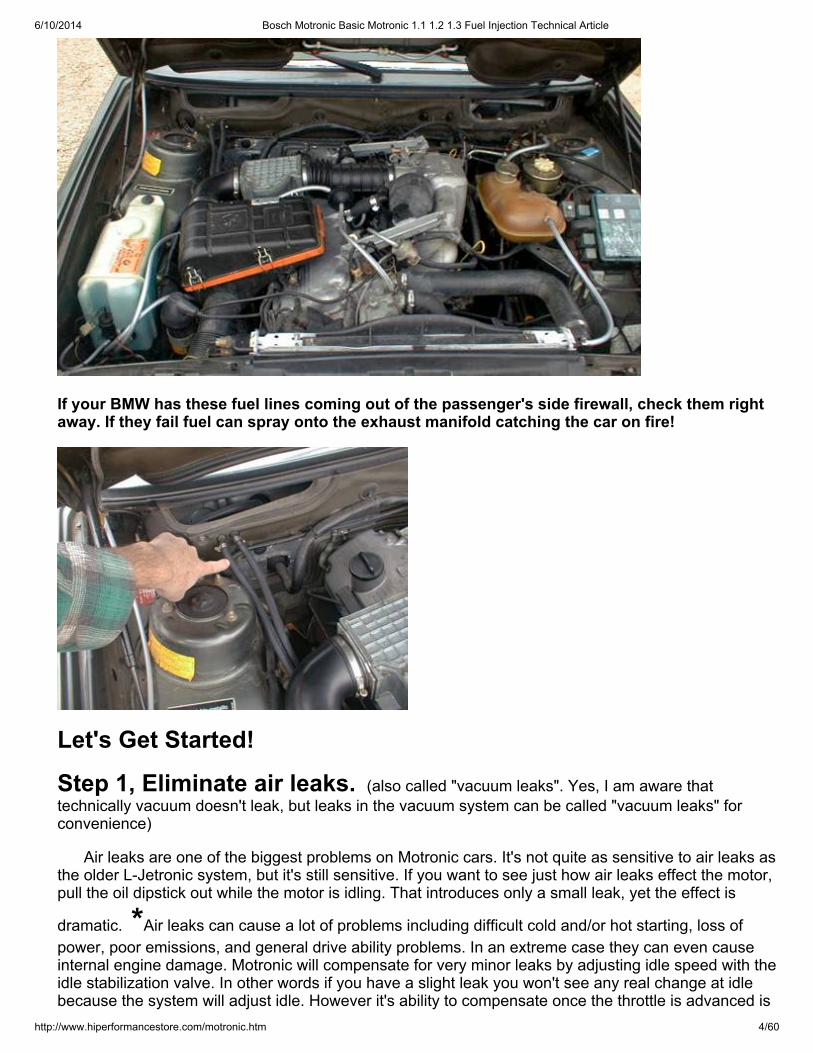
If your BMW has these fuel lines coming out of the passenger's side firewall, check them rightaway. If they fail fuel can spray onto the exhaust manifold catching the car on fire!
Let's Get Started!
Step 1, Eliminate air leaks. (also called "vacuum leaks". Yes, I am aware thattechnically vacuum doesn't leak, but leaks in the vacuum system can be called "vacuum leaks" forconvenience)
Air leaks are one of the biggest problems on Motronic cars. It's not quite as sensitive to air leaks asthe older L-Jetronic system, but it's still sensitive. If you want to see just how air leaks effect the motor,pull the oil dipstick out while the motor is idling. That introduces only a small leak, yet the effect is
dramatic. *Air leaks can cause a lot of problems including difficult cold and/or hot starting, loss ofpower, poor emissions, and general drive ability problems. In an extreme case they can even causeinternal engine damage. Motronic will compensate for very minor leaks by adjusting idle speed with theidle stabilization valve. In other words if you have a slight leak you won't see any real change at idlebecause the system will adjust idle. However it's ability to compensate once the throttle is advanced is
6/10/2014 Bosch Motronic Basic Motronic 1.1 1.2 1.3 Fuel Injection Technical Article
http://www.hiperformancestore.com/motronic.htm 5/60
marginal at best.
Air leaks cause problems for two reasons. First, the Motronic system measures the volume anddensity of the air passing through the air flow meter and sends that information to the fuel injectioncomputer also called the ECU. The ECU then calculates fuel requirements based largely on thatinformation. If an air leak allows air to enter the system downstream of the airflow meter then the ECUhas no accurate measurement of how much air is entering the engine. The second problem is thatvarious devices including the fuel pressure regulator and evaporative purge valve (both discussed indetail later) as well as many other components require vacuum to function properly. An air leak will notonly introduce un metered air into the system it will prevent important components from workingproperly.
It makes sense to start troubleshooting by looking for air leaks. This is because they are a possibleand common cause of nearly every fault, and they are about the easiest and cheapest problems tosolve. You don't want to throw hundreds of dollars in parts at a problem only to find out it was an airleak.
Lets start by looking at the main air intake tube or "rubber boot" that connects the throttle body tothe air flow meter. This thing has a lot of potential for leaks. It should be inspected very carefully forcracks. They tend to form on the bottom of the tube so you really need to remove it to properly inspectit. If it has any cracks it should be replaced. If you can't replace it because you can't find the part, ordue to economic realities I suggest using "Shoo Goo" from the sporting goods section of Wal Mart. Ihave also found it in the shoe section of Wal Mart (by the shoe laces and polish). This product isdesigned for repairing the soles of tennis shoes and will seal up any air leaks on this tube. (don'tlaugh, Shoo Goo lasts almost forever in this application)
Next start inspecting all the vacuum lines in the engine compartment. All of them are related to thefuel injection system in some way, and a leak in any of them can cause problems. This can be timeconsuming because a lot of these vacuum lines are hard to see and have to be removed to beinspected effectively. If your lines are 20 years old they will probably have to be replaced. They arealmost certainly cracked and brittle with age and it will be very difficult to remove them without crackingthem. (Sales pitch alert!!! Our silicone hose kit has all the vacuum lines pre cut for the 535i andincludes easy to follow step-by-step instructions and diagrams. It also includes all the windshieldwasher hoses, and a couple coolant hoses. We use very high quality silicone and the lines shouldoutlast everything else under the hood. It can be found here:http://www.hiperformancestore.com/BMW.htm all BMW Silicone Vacuum Hose Kits Link )
BMW E34 M5 Additional vacuum system data:Resonance Flap Control and Air Injection Control:
The S38 engines found in these cars have a significantly different vacuum system. Most of the
differences are related to the “resonance flap control system”. *This system is important forperformance and if faulty will cause a loss of horsepower and torque in certain conditions. It can alsocause other minor running issues, like poor response, irregular idle, or high emissions.
The resonance system is confusing as heck. Let’s talk about it. The system uses a flap inside theplenum to essentially divide the plenum into halves whenever maximum performance is needed, thatmeans full throttle.
However, under certain conditions, the engine is happier without the plenum divided. So at partthrottle, or at full throttle but between 4120 and 6720rpm the flap is open and the plenum is notdivided.
6/10/2014 Bosch Motronic Basic Motronic 1.1 1.2 1.3 Fuel Injection Technical Article
http://www.hiperformancestore.com/motronic.htm 6/60
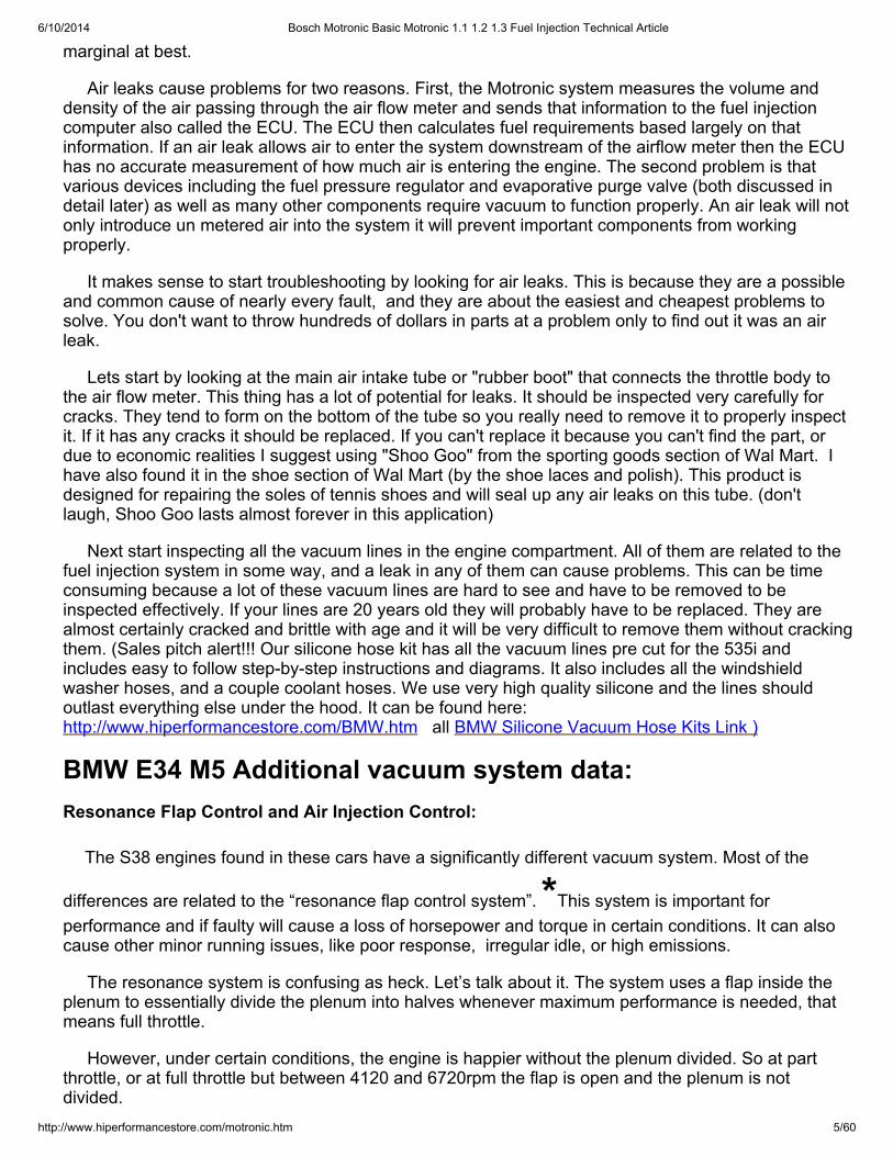
OK, the picture below shows the two different paths the air takes. The picture on the RIGHT isthe flap closed plenum divided picture. There is a lot of confusion about this because the“throttle valve mentioned in the diagram refers to the flap inside the plenum and NOT the sixindividual throttles.
From a performance standpoint, the entire point of this system is to increase torque between4120rpm and 6720rpm. At full throttle outside of that RPM range, the flap is closed and the plenum isdivided. For reasons having to do with resonance, at full throttle the engine makes more torque withthe flap open within a certain rpm range so the system provides the engine with two different plenumconfigurations while at full throttle.
When not at full throttle, the flap is open and the plenum is not divided. This improves the engine’soperation at part throttle.
OK, so that’s what it does, but how does it work? Well, it’s electronically controlled, but VACUUMactivated. There is an actuator that uses vacuum to operate the flap. There is a component called achange over valve. This valve either lets vacuum reach the actuator to close the flap, or it doesn’t, inwhich case the flap opens due to spring pressure. The changeover valve gets it’s signal from theresonance flap control unit, which knows throttle position and engine rpm.
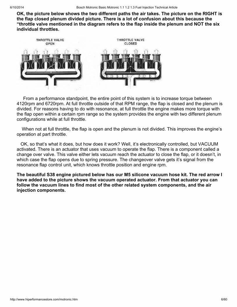
The beautiful S38 engine pictured below has our M5 silicone vacuum hose kit. The red arrow Ihave added to the picture shows the vacuum operated actuator. From that actuator you canfollow the vacuum lines to find most of the other related system components, and the airinjection components.
6/10/2014 Bosch Motronic Basic Motronic 1.1 1.2 1.3 Fuel Injection Technical Article
http://www.hiperformancestore.com/motronic.htm 7/60
Blatant commercial comment: We have vacuum hose kits for all 6 cylinder M5s. Our E34 kit shownhere is available in 7 different colors. We have even had some customers order the kits with acombination of Blue, Purple, and Red hoses for the “M” color scheme. There are a lot of vacuumhoses on these cars, many of which are not visible in this photo. Our kit replaces them all as well asthe oil drain hoses out of the plenum, and various coolant hoses, and it includes a vacuum diagram.We also have silicone radiator hoses for the E34 M5. End of commercial J
OK, so, the system uses vacuum from the intake plenum to physically move the flap into the closeposition. It will move it twice if you run it at full throttle through the entire rpm range. When you first goto full throttle at low rpm, it will close the flap, allow it to reopen at 4120rpm and close it again at 6720.Are you seeing a big problem here? I am, and so did the BMW engineers. At full throttle there isn’tenough vacuum in a well designed performance intake plenum to move anything, let alone to movethis valve twice before the driver shifts. So, they installed a vacuum reservoir. The reservoir storesenough vacuum to move the actuator six times. When you let off on the throttle to shift, or when drivinglike a normal human being, the reservoir stores up some vacuum to move the valve when needed. Italso stores vacuum for the system’s self test when it moves the valve right after engine start.
The reservoir itself has a check valve, and vacuum lines associated with it. These are all included inour silicone vacuum hose kit. A loss of vacuum is big problem for these cars.
Oh, and just for more fun, the BMW engineers decided to use the same reservoir to provide vacuumfor the Air Injection System, so let’s go over that.
6/10/2014 Bosch Motronic Basic Motronic 1.1 1.2 1.3 Fuel Injection Technical Article
http://www.hiperformancestore.com/motronic.htm 8/60
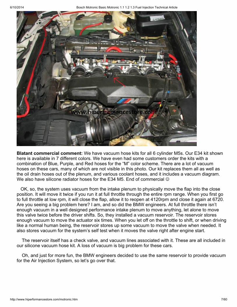
Resonance Flap Control and Air Injection Control systems are connected by vacuum lines.They both use manifold vacuum from the same hose through the same reservoir.
The air injection system is designed to inject air into the exhaust for the sole purpose of reducingemissions. The system does NOT run all the time. It uses an air pump with a magnetic clutch. When
the clutch is engaged, it pumps air, at all other times it just sits there. *Problems with the air injectionsystem can cause high emissions, and if various valves fail, it can allow exhaust into the vacuumsystem. If enough check valves failed or if the system was connected incorrectly it could cause all
6/10/2014 Bosch Motronic Basic Motronic 1.1 1.2 1.3 Fuel Injection Technical Article
http://www.hiperformancestore.com/motronic.htm 9/60
sorts of running problems. It can also allow air into the exhaust when it’s not called for thus giving theO2 sensor a false lean reading.
Let’s talk for a moment about what an air injection system does. The theory is that injecting air intothe exhaust manifold will clean up the exhaust by allowing unburned fuel to burn up. Many, probablymost cars build in the late 70’s had these systems. However they didn’t work very well at actuallyimproving emissions. It’s more likely they increased emissions which is one of the reasons they startedto vanish in the 80’s are and essentially disappeared by 1995. What they do VERY well is give theillusion of cleaner emissions. If you live in a state like California, you have probably been through asmog check. One of the things they look for on this check is unburned hydrocarbons. That’s great, butthey measure this pollutant in particles per million (ppm). Pumping air into the exhaust reduces thepollution in terms of ppm largely because it’s adding non pollutants to the equation. In other words andin simple math, if you had 50ppm, out of 1million total particles, then added another million particles ofnon pollutants your ppm would drop to 25, although you didn’t really reduce pollution one bit. In fact, inthis example you probably increased it because you had to burn fuel to pump that extra air.
This is the big problem with the air pump, it add complexity, weight, expense, and requires burninga small about of extra fuel to operate, yet the real benefits are marginal at best. That said, you needthe dang thing to work, or passing a smog check will be difficult.
OK, so why does the E34 M5 have this when neither the E28 M5 nor 535i have it? Simple, oneword, camshafts. The E34 M5 has cams with both higher lift and longer duration. In order to get it toidle during the warm up period they needed to run a relatively rich mixture, and that leads to highhydrocarbons in the exhaust. An air pump is a guaranteed way to get the numbers down into thepassable range without redesigning any actual engine components.
OK, back to the actual system. As I said, it doesn’t run all the time. It fact, it only runs for 125seconds before it shuts off. It runs during the warm up period as determined by a coolant temp of86F(30C). It also runs while the engine is being started. Additionally it never runs when the engine isabove 4600rpm, probably to avoid adversely affecting published horsepower numbers, or possibly toavoid over-speeding the pump.
So, how does this thing work? When the above conditions are met, a relay (number 8 in thediagram) provides power to engage a magnetic clutch on the air pump and cause it to start pumping.At the same time it provides power to the change over valve (10) which will allow vacuum to open thevacuum controlled valve (11). From there air flows through a check valve and into the exhaust. Thecheck valve prevents exhaust from flowing the other way when the pump isn’t running. If you haveexhaust in your vacuum system, take a look at that check valve.
The vacuum controlled valve is the valve that opens to let air into the exhaust. When closed itprevents any venturi effect in the exhaust manifold from drawing air in when the air injection system isnot operation thus causing a false lean reading from the O2 sensor. If the pump engages and thevacuum controlled valve doesn’t open, the air will blow out through the pressure control valve (13),thus preventing damage to the system.
That’s it for the air injection system. The parts of the system are very reliable, and most problemsreally do relate to the hoses, so replace them with high quality high temperature hoses right away!
Step 2, Test the evaporative emission system.
6/10/2014 Bosch Motronic Basic Motronic 1.1 1.2 1.3 Fuel Injection Technical Article
http://www.hiperformancestore.com/motronic.htm 10/60
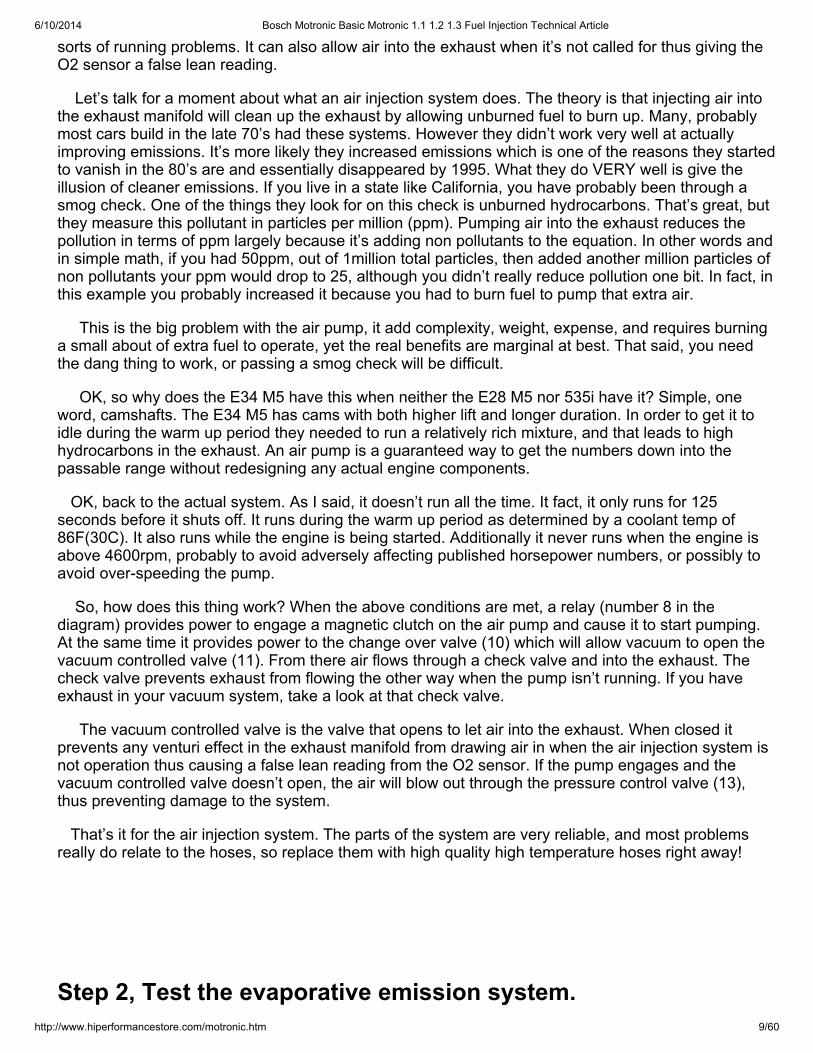
Pictured below is the main intake tube called the "rubber boot" in the BMW manual. The valveattached to it is the Evaporative Purge Valve called the "air valve" in the BMW manual.
Attached to the tube on the forward side is the "air valve". This valve is designed to open when thethrottle is closed or nearly closed with the engine running (in other words at high vacuum/low manifoldpressure conditions). When it opens it allows vapors from the charcoal canister to enter the motor.Give the valve a good visual inspection to make sure it's not cracked. Check its connection to theintake tube. If it looks like it leaks replace it or use the Shoe Goo technique.
Once you are sure the valve is OK on the outside, we need to make sure the thing actually works.You will need a helper for this. Get the wife or girlfriend to help with this one! First you need to blow onthe larger port ( the one with the green tube in the picture ). Air should not go through unless you blowreally hard and force it open. Now have your helper suck on the smaller port ( the one with the redtube ). While your helper is sucking, the valve should open and you should easily be able to blow airthrough the larger port. If it fails either one of these tests you have to replace it.
On the other side of the tube is the Idle Stabilization Valve. This is the cylinder that has an electricalplug on the end near the firewall. This item is explained and tested later in this article. For now justmake sure its connection to the tube is leak free.
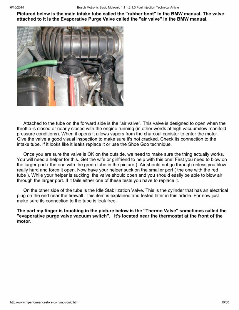
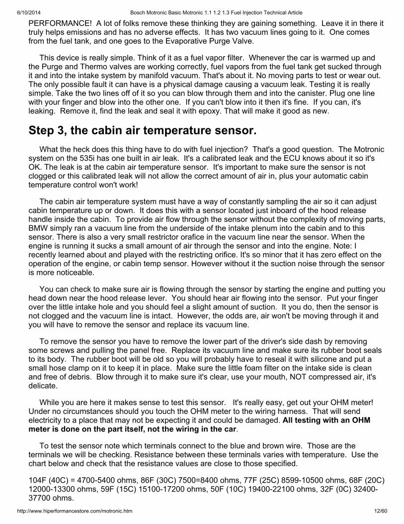
The part my finger is touching in the picture below is the "Thermo Valve" sometimes called the"evaporative purge valve vacuum switch". It's located near the thermostat at the front of themotor.
6/10/2014 Bosch Motronic Basic Motronic 1.1 1.2 1.3 Fuel Injection Technical Article
http://www.hiperformancestore.com/motronic.htm 11/60
The Thermo Valve's entire purpose in life is to shut off the evaporative emission system until theengine is warmed up (meaning a coolant temperature of 110F ( 44C ). It's immersed in coolant soonce the coolant temp reaches the specified amount it opens up allowing engine vacuum to reach theevaporative purge valve we just tested, thus allowing fuel vapors to be sucked through the charcoal
canister and into the motor. When the coolant temp drops below about 92F ( 34C ) it closes again. *Afaulty Thermo Valve can cause irregular running during the warm up period if it's stuck open. If it'sstuck closed it will have an adverse effect on emissions.
Testing this thing is really easy. With the engine cold, pull both its vacuum lines off at the otherends (that means not off the thermo valve). Now blow into one line. Air should not go anywhere, thevalve should be closed stopping you from blowing any air through it. Put everything back together,start and run the motor until it warms up. Shut the motor off, pull the lines off again and blow throughone. The valve should be open and you should be able to blow right through the valve.
Note: If the Thermo Valve and the Evaporative Purge Valve are functioning correctly and your carhas a problem only when cold then it's not a problem related to the Evaporative emission system.
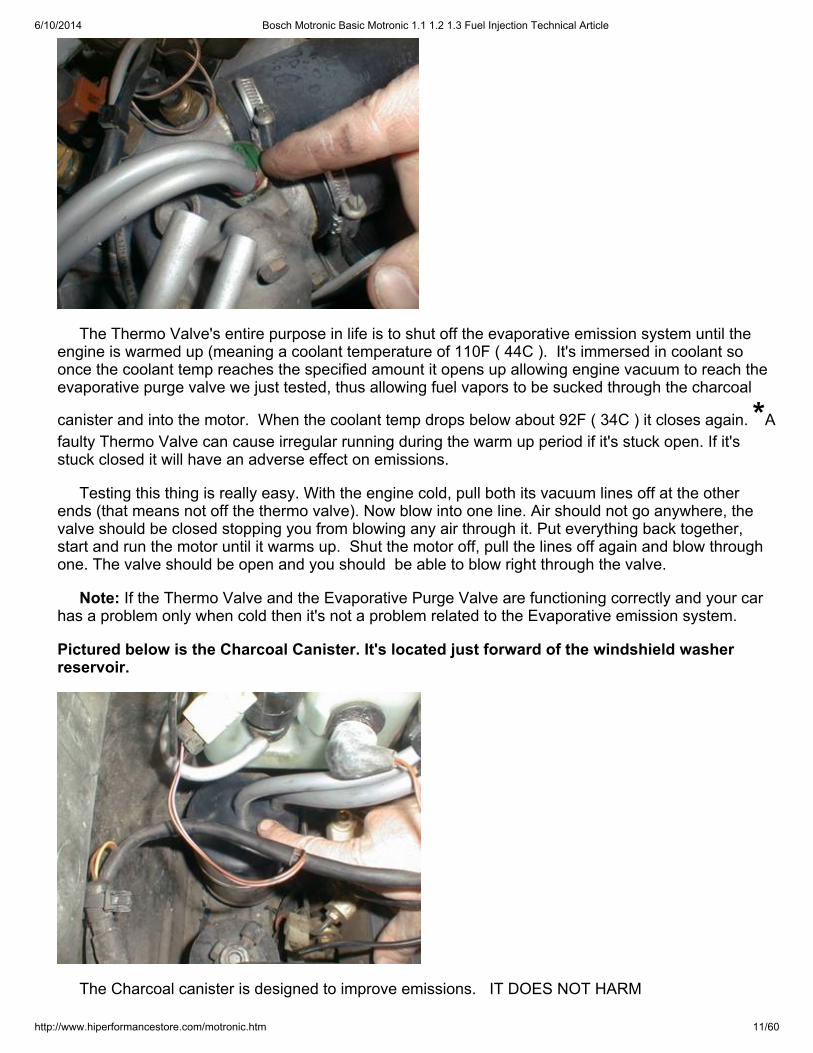
Pictured below is the Charcoal Canister. It's located just forward of the windshield washerreservoir.
The Charcoal canister is designed to improve emissions. IT DOES NOT HARM
6/10/2014 Bosch Motronic Basic Motronic 1.1 1.2 1.3 Fuel Injection Technical Article
http://www.hiperformancestore.com/motronic.htm 12/60
PERFORMANCE! A lot of folks remove these thinking they are gaining something. Leave it in there ittruly helps emissions and has no adverse effects. It has two vacuum lines going to it. One comesfrom the fuel tank, and one goes to the Evaporative Purge Valve.
This device is really simple. Think of it as a fuel vapor filter. Whenever the car is warmed up andthe Purge and Thermo valves are working correctly, fuel vapors from the fuel tank get sucked throughit and into the intake system by manifold vacuum. That's about it. No moving parts to test or wear out.The only possible fault it can have is a physical damage causing a vacuum leak. Testing it is reallysimple. Take the two lines off of it so you can blow through them and into the canister. Plug one linewith your finger and blow into the other one. If you can't blow into it then it's fine. If you can, it'sleaking. Remove it, find the leak and seal it with epoxy. That will make it good as new.
Step 3, the cabin air temperature sensor. What the heck does this thing have to do with fuel injection? That's a good question. The Motronicsystem on the 535i has one built in air leak. It's a calibrated leak and the ECU knows about it so it'sOK. The leak is at the cabin air temperature sensor. It's important to make sure the sensor is notclogged or this calibrated leak will not allow the correct amount of air in, plus your automatic cabintemperature control won't work!
The cabin air temperature system must have a way of constantly sampling the air so it can adjustcabin temperature up or down. It does this with a sensor located just inboard of the hood releasehandle inside the cabin. To provide air flow through the sensor without the complexity of moving parts,BMW simply ran a vacuum line from the underside of the intake plenum into the cabin and to thissensor. There is also a very small restrictor orafice in the vacuum line near the sensor. When theengine is running it sucks a small amount of air through the sensor and into the engine. Note: Irecently learned about and played with the restricting orifice. It's so minor that it has zero effect on theoperation of the engine, or cabin temp sensor. However without it the suction noise through the sensoris more noticeable.
You can check to make sure air is flowing through the sensor by starting the engine and putting youhead down near the hood release lever. You should hear air flowing into the sensor. Put your fingerover the little intake hole and you should feel a slight amount of suction. It you do, then the sensor isnot clogged and the vacuum line is intact. However, the odds are, air won't be moving through it andyou will have to remove the sensor and replace its vacuum line.
To remove the sensor you have to remove the lower part of the driver's side dash by removingsome screws and pulling the panel free. Replace its vacuum line and make sure its rubber boot sealsto its body. The rubber boot will be old so you will probably have to reseal it with silicone and put asmall hose clamp on it to keep it in place. Make sure the little foam filter on the intake side is cleanand free of debris. Blow through it to make sure it's clear, use your mouth, NOT compressed air, it'sdelicate.
While you are here it makes sense to test this sensor. It's really easy, get out your OHM meter! Under no circumstances should you touch the OHM meter to the wiring harness. That will sendelectricity to a place that may not be expecting it and could be damaged. All testing with an OHMmeter is done on the part itself, not the wiring in the car.
To test the sensor note which terminals connect to the blue and brown wire. Those are theterminals we will be checking. Resistance between these terminals varies with temperature. Use thechart below and check that the resistance values are close to those specified.
104F (40C) = 4700-5400 ohms, 86F (30C) 7500=8400 ohms, 77F (25C) 8599-10500 ohms, 68F (20C)12000-13300 ohms, 59F (15C) 15100-17200 ohms, 50F (10C) 19400-22100 ohms, 32F (0C) 32400-37700 ohms.

6/10/2014 Bosch Motronic Basic Motronic 1.1 1.2 1.3 Fuel Injection Technical Article
http://www.hiperformancestore.com/motronic.htm 13/60
This picture shows me testing the cabin air temperature sensor. The air temperature wasabout 65F and it registered 12,480 ohms, just about right. I doubt you will ever see one thatdoesn't test correctly. The issues with these things are a clogged inlet and inadequate vacuumto the sensor.
Step 4, Motronic Powering UP! Electrical power supply andgrounds.
Now we will start to go deeper into the Motronic system. *Problems with the system's powersupply and or grounds will often cause the engine to quit running and or prevent the car from starting. If your car cranks over but won't start, this is probably the section for you.
Powering up check.
First we need to see if the Motronic system is powering up. *If it doesn't your car won't run. WithMotronic Basic we will have to remove a connector from a fuel injector. It's easiest to remove it fromthe forward most injector. These connectors are normally grey in color. Carefully remove the metalretaining clip with a tiny screwdriver. DO NOT try to force off the connector until you have removedthat clip or damage to the connector will result.
Next turn on the ignition and connect your voltmeter to an electrical contact in the connector (eitherone) and a ground, you should see battery voltage or very close to it. If you don't have a voltmeter youcould use a test light, but a voltmeter is better.
DANGER DANGER!!! Make sure your multi meter is NOT selected to Ohms. If it is, it will sendcurrent into the Motronic control unit (the ECU). As a general rule, power going into the ECU whereit's not supposed to is bad. Damage could result. Make sure it's selected to read voltage. As ageneral rule, when we are checking something at the wiring harness, it's voltage, when checking anactual component we are checking Ohms.
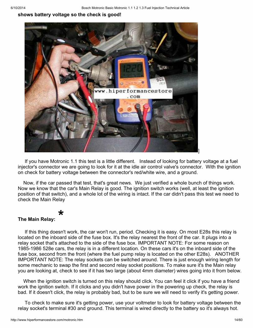
The picture below shows this test on a Motronic Basic car. The voltmeter's red wire istouching the connector, the black is grounded to the manifold support bracket. The voltmeter
6/10/2014 Bosch Motronic Basic Motronic 1.1 1.2 1.3 Fuel Injection Technical Article
http://www.hiperformancestore.com/motronic.htm 14/60
shows battery voltage so the check is good!
]
If you have Motronic 1.1 this test is a little different. Instead of looking for battery voltage at a fuelinjector's connector we are going to look for it at the idle air control valve's connector. With the ignitionon check for battery voltage between the connector's red/white wire, and a ground.
Now, if the car passed that test, that's great news. We just verified a whole bunch of things work. Now we know that the car's Main Relay is good. The ignition switch works (well, at least the ignitionposition of that switch), and a whole lot of the wiring is intact. If the car didn't pass this test we need tocheck the Main Relay
The Main Relay: * If this thing doesn't work, the car won't run, period. Checking it is easy. On most E28s this relay islocated on the inboard side of the fuse box. It's the relay nearest the front of the car. It plugs into arelay socket that's attached to the side of the fuse box. IMPORTANT NOTE: For some reason on1985-1986 528e cars, the relay is in a different location. On these cars it's on the inboard side of thefuse box, second from the front (where the fuel pump relay is located on the other E28s). ANOTHERIMPORTANT NOTE: The relay sockets can be switched around. There is just enough wiring length forsome mechanic to swap the first and second relay socket positions. To make sure it's the Main relayyou are looking at, check to see if it has two large (about 4mm diameter) wires going into it from below.
When the ignition switch is turned on this relay should click. You can feel it click if you have a friendwork the ignition switch. If it clicks and you didn't have power in the powering up check, the relay isbad. If it doesn't click, the relay is probably bad, but to be sure we will need to verify it's getting power.
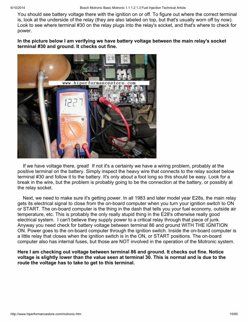
To check to make sure it's getting power, use your voltmeter to look for battery voltage between therelay socket's terminal #30 and ground. This terminal is wired directly to the battery so it's always hot.
6/10/2014 Bosch Motronic Basic Motronic 1.1 1.2 1.3 Fuel Injection Technical Article
http://www.hiperformancestore.com/motronic.htm 15/60
You should see battery voltage there with the ignition on or off. To figure out where the correct terminalis, look at the underside of the relay (they are also labeled on top, but that's usually worn off by now).Look to see where terminal #30 on the relay plugs into the relay's socket, and that's where to check forpower.
In the picture below I am verifying we have battery voltage between the main relay's socketterminal #30 and ground. It checks out fine.
If we have voltage there, great! If not it's a certainty we have a wiring problem, probably at thepositive terminal on the battery. Simply inspect the heavy wire that connects to the relay socket belowterminal #30 and follow it to the battery. It's only about a foot long so this should be easy. Look for abreak in the wire, but the problem is probably going to be the connection at the battery, or possibly atthe relay socket.
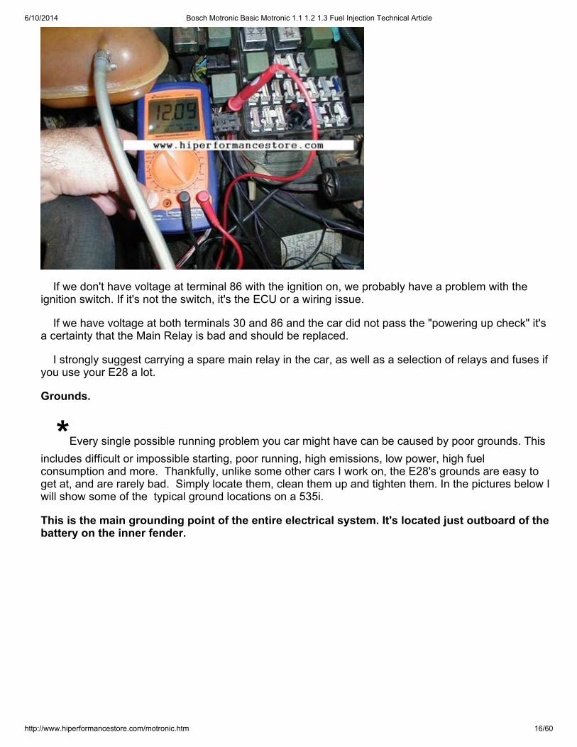
Next, we need to make sure it's getting power. In all 1983 and later model year E28s, the main relaygets its electrical signal to close from the on-board computer when you turn your ignition switch to ONor START. The on-board computer is the thing in the dash that tells you your fuel economy, outside airtemperature, etc. This is probably the only really stupid thing in the E28's otherwise really goodelectrical system. I can't believe they supply power to a critical relay through that piece of junk.Anyway you need check for battery voltage between terminal 86 and ground WITH THE IGNITIONON. Power goes to the on-board computer through the ignition switch. Inside the on-board computer isa little relay that closes when the ignition switch is in the ON, or START positions. The on-boardcomputer also has internal fuses, but those are NOT involved in the operation of the Motronic system.
Here I am checking out voltage between terminal 86 and ground. It checks out fine. Noticevoltage is slightly lower than the value seen at terminal 30. This is normal and is due to theroute the voltage has to take to get to this terminal.
6/10/2014 Bosch Motronic Basic Motronic 1.1 1.2 1.3 Fuel Injection Technical Article
http://www.hiperformancestore.com/motronic.htm 16/60
If we don't have voltage at terminal 86 with the ignition on, we probably have a problem with theignition switch. If it's not the switch, it's the ECU or a wiring issue.
If we have voltage at both terminals 30 and 86 and the car did not pass the "powering up check" it'sa certainty that the Main Relay is bad and should be replaced.
I strongly suggest carrying a spare main relay in the car, as well as a selection of relays and fuses ifyou use your E28 a lot.
Grounds.
*Every single possible running problem you car might have can be caused by poor grounds. Thisincludes difficult or impossible starting, poor running, high emissions, low power, high fuelconsumption and more. Thankfully, unlike some other cars I work on, the E28's grounds are easy toget at, and are rarely bad. Simply locate them, clean them up and tighten them. In the pictures below Iwill show some of the typical ground locations on a 535i.
This is the main grounding point of the entire electrical system. It's located just outboard of thebattery on the inner fender.
6/10/2014 Bosch Motronic Basic Motronic 1.1 1.2 1.3 Fuel Injection Technical Article
http://www.hiperformancestore.com/motronic.htm 17/60
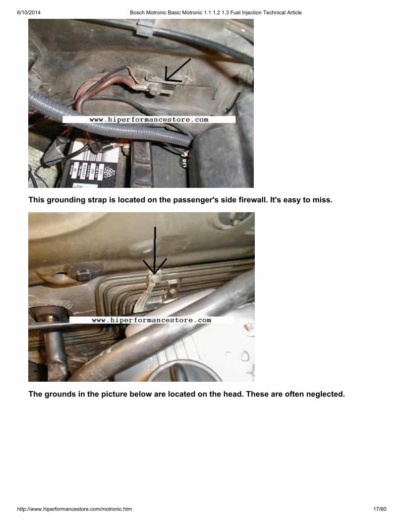
This grounding strap is located on the passenger's side firewall. It's easy to miss.
The grounds in the picture below are located on the head. These are often neglected.
6/10/2014 Bosch Motronic Basic Motronic 1.1 1.2 1.3 Fuel Injection Technical Article
http://www.hiperformancestore.com/motronic.htm 18/60
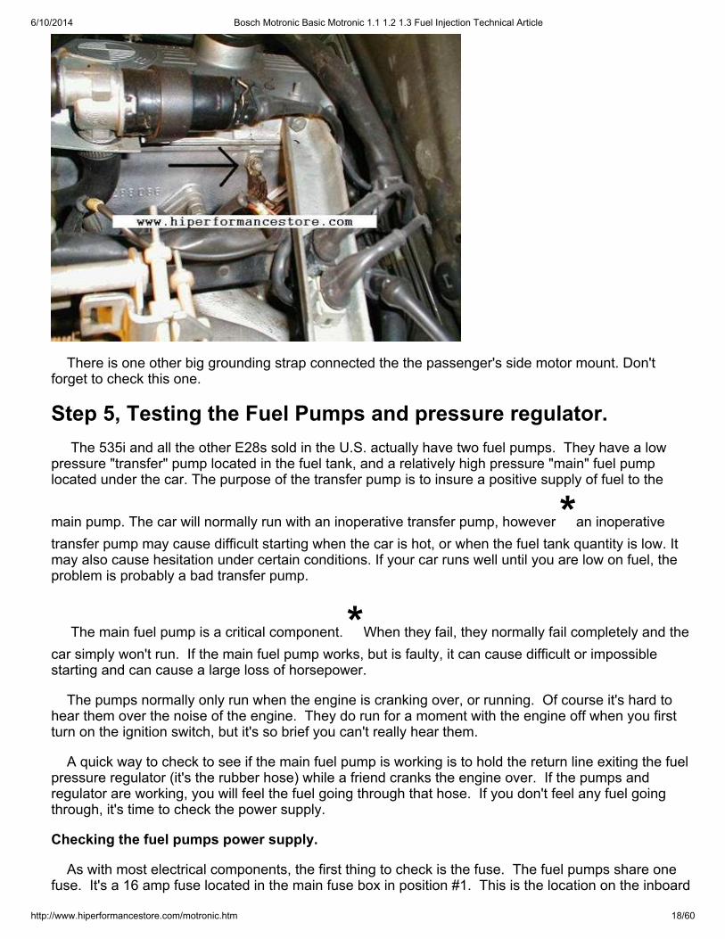
There is one other big grounding strap connected the the passenger's side motor mount. Don'tforget to check this one.
Step 5, Testing the Fuel Pumps and pressure regulator. The 535i and all the other E28s sold in the U.S. actually have two fuel pumps. They have a lowpressure "transfer" pump located in the fuel tank, and a relatively high pressure "main" fuel pumplocated under the car. The purpose of the transfer pump is to insure a positive supply of fuel to the
main pump. The car will normally run with an inoperative transfer pump, however *an inoperativetransfer pump may cause difficult starting when the car is hot, or when the fuel tank quantity is low. Itmay also cause hesitation under certain conditions. If your car runs well until you are low on fuel, theproblem is probably a bad transfer pump.
The main fuel pump is a critical component. *When they fail, they normally fail completely and thecar simply won't run. If the main fuel pump works, but is faulty, it can cause difficult or impossiblestarting and can cause a large loss of horsepower.
The pumps normally only run when the engine is cranking over, or running. Of course it's hard tohear them over the noise of the engine. They do run for a moment with the engine off when you firstturn on the ignition switch, but it's so brief you can't really hear them.
A quick way to check to see if the main fuel pump is working is to hold the return line exiting the fuelpressure regulator (it's the rubber hose) while a friend cranks the engine over. If the pumps andregulator are working, you will feel the fuel going through that hose. If you don't feel any fuel goingthrough, it's time to check the power supply.
Checking the fuel pumps power supply.
As with most electrical components, the first thing to check is the fuse. The fuel pumps share onefuse. It's a 16 amp fuse located in the main fuse box in position #1. This is the location on the inboard
6/10/2014 Bosch Motronic Basic Motronic 1.1 1.2 1.3 Fuel Injection Technical Article
http://www.hiperformancestore.com/motronic.htm 19/60
side of the box all the way towards the front of the car. In other words, it's located in the front inboardcorner position. If this fuse is blown, or has bad contacts, the pumps, and thus the engine will not run. Check the fuse and the contacts.
Next, we should check the fuel pump relay. On the 535i this relay is located just aft of the MainRelay we checked earlier. Make sure it's not the main relay, as the positions of the relay sockets canbe swapped around as I explained in "The Main Relay" section of this article.
On the 535i with the ignition switch off, there should be approximately battery voltage between thefuel pump relay socket's terminal #30 and ground. In the unusual case of the 1982 528e, the ignitionmust be on for this test (ignition switch in run, or start positions).
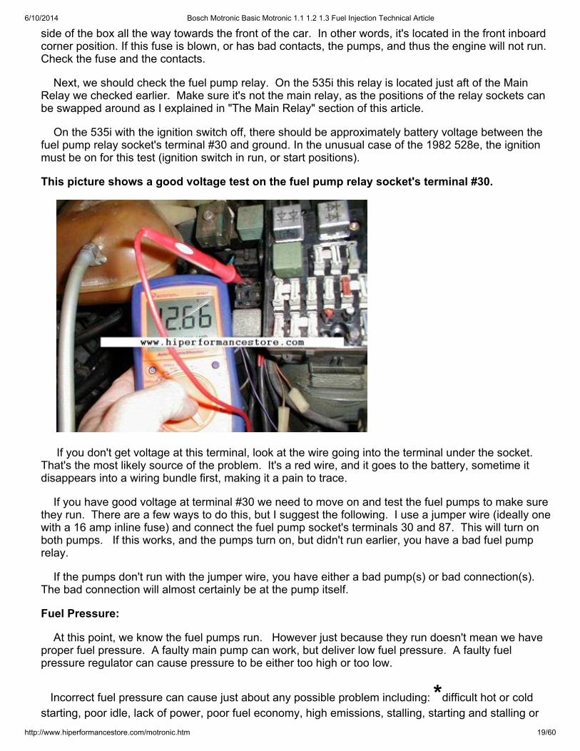
This picture shows a good voltage test on the fuel pump relay socket's terminal #30.
If you don't get voltage at this terminal, look at the wire going into the terminal under the socket. That's the most likely source of the problem. It's a red wire, and it goes to the battery, sometime itdisappears into a wiring bundle first, making it a pain to trace.
If you have good voltage at terminal #30 we need to move on and test the fuel pumps to make surethey run. There are a few ways to do this, but I suggest the following. I use a jumper wire (ideally onewith a 16 amp inline fuse) and connect the fuel pump socket's terminals 30 and 87. This will turn onboth pumps. If this works, and the pumps turn on, but didn't run earlier, you have a bad fuel pumprelay.
If the pumps don't run with the jumper wire, you have either a bad pump(s) or bad connection(s).The bad connection will almost certainly be at the pump itself.
Fuel Pressure:
At this point, we know the fuel pumps run. However just because they run doesn't mean we haveproper fuel pressure. A faulty main pump can work, but deliver low fuel pressure. A faulty fuelpressure regulator can cause pressure to be either too high or too low.
Incorrect fuel pressure can cause just about any possible problem including: *difficult hot or coldstarting, poor idle, lack of power, poor fuel economy, high emissions, stalling, starting and stalling or
6/10/2014 Bosch Motronic Basic Motronic 1.1 1.2 1.3 Fuel Injection Technical Article
http://www.hiperformancestore.com/motronic.htm 20/60
any combination of these.
Let's take a break from testing things for a moment to discuss fuel pressure. This may be a littleconfusing so you may have to read it twice. I know I would. Proper fuel pressure is very important onthe E28s. The Motronic ECU maintains control of the fuel air mixture by measuring the engine's airintake and then injecting in the proper amount of fuel. It controls fuel delivery exclusively by controllingthe amount of time the fuel injectors are open (except during starting, which will be covered later). Iffuel pressure is too high or too low the ECU won't know it, and at idle or full throttle it will make noattempt to compensate. Under these conditions if fuel pressure is too high the injectors will allow toomuch fuel to spray in because the ECU won't know to reduce the amount of time they are open. If it'stoo low, we have the opposite problem. The Motronic system can compensate for small variations infuel pressure during normal driving (i.e. not during starting, warm up, idle, or high power operations). It does this via inputs from the O2 sensor. We will cover that later.
Before we get into testing fuel pressure, let's go over how much fuel pressure these cars shouldhave. With the engine off, and the pumps running the 535i should have 43.5psi +/- .9psi. For youMetric guys, that's 3 bar, +/- .6 bar. Under the same conditions the 533i and 528e should have36.3psi +/-.7 psi. If you love the Metric system that's 2.5 bar +/-.06 bar.
Of course it has to get more complicated than that! Notice those numbers are with the engine off. The actual values with the engine running MUST vary. Follow along to understand why. The pressureregulator is not designed to hold the pressure at a fixed value. It IS designed to hold the pressuredifferential between the fuel pressure at the inlet side of the injectors, and the air pressure in themanifold constant. Think of it this way. If our system held fuel pressure at a constant 36 psi and wehad 37 psi of air pressure in the intake manifold when the fuel injectors opened, fuel would not flowinto the manifold. Instead air would flow into the fuel system. Of course on a stock E28 that can'thappen because manifold pressure in these cars will rarely exceed 15psi. The point is that if fuelpressure was constant, then variations in manifold pressure would affect the amount of fuel injected fora given injector duration period.
Manifold pressure in these cars varies from about 7psi to about 15psi depending on throttle position,rpm, etc. In order to keep the fuel pressure differential constant the pressure regulator raises andlowers fuel pressure in response to changes in manifold pressure. With the engine idling we shouldsee 42 psi on a 535i, and about 34psi on a 533i or 528e (Note, the actual number may vary. Theofficial range is 40.6-46.4 on the 535i and 33.4-39.0 on the 533i/528e). What's important here is thatthe value is lower with the engine idling than it was with the engine off. If you remove the vacuum linefrom the fuel pressure regulator it will think the engine is at or near full throttle and fuel pressure shouldincrease to about the value normally seen with the engine off. What's important here is that it doesincrease when you remove the vacuum line.
Important Note For Turbo and Supercharged applications: If you have one of the ultra rareturbo BMWs with this system (i.e. E23 745i) fuel pressure must increase directly with boost. Forexample at 5psi of boost, fuel pressure should go up 5psi. If you are doing a turbo or superchargedconversion on your E28, E24, or other Motronic BMW this is still true. On that subject Motronic withvarious inexpensive modifications is well suited to these projects up to about 10 pounds of boost. However that's another article for another time. If you are supercharging or turbo charging an E28and need help, feel free to contact me. In regards to forced induction I can provide good tech help forBosch L-Jetronic, Early Motronic, SDS brand fuel injection, water and water/methanol injection, andsupercharger selection. I don’t provide any tech help for any other fuel injection systems.
Testing the Fuel Pressure. Under Construction
Now that we understand how fuel pressure should react, and we know what values to look for, let'stest the main pump and regulator for proper pressure.
6/10/2014 Bosch Motronic Basic Motronic 1.1 1.2 1.3 Fuel Injection Technical Article
http://www.hiperformancestore.com/motronic.htm 21/60
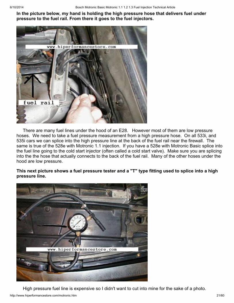
In the picture below, my hand is holding the high pressure hose that delivers fuel underpressure to the fuel rail. From there it goes to the fuel injectors.
There are many fuel lines under the hood of an E28. However most of them are low pressurehoses. We need to take a fuel pressure measurement from a high pressure hose. On all 533i, and535i cars we can splice into the high pressure line at the back of the fuel rail near the firewall. Thesame is true of the 528e with Motronic 1.1 injection. If you have a 528e with Motronic Basic splice intothe fuel line going to the cold start injector (often called a cold start valve). Make sure you are splicinginto the the hose that actually connects to the back of the fuel rail. Many of the other hoses under thehood are low pressure.
This next picture shows a fuel pressure tester and a "T" type fitting used to splice into a highpressure line.
High pressure fuel line is expensive so I didn't want to cut into mine for the sake of a photo.
6/10/2014 Bosch Motronic Basic Motronic 1.1 1.2 1.3 Fuel Injection Technical Article
http://www.hiperformancestore.com/motronic.htm 22/60
However, from the two pictures above, it should be pretty easy to see how and where to take thepressure reading.
Once you have your fuel pressure tester connected. Get your fire extinguisher ready. With theengine off energize the fuel pump via the fused jumper wire described in the "Checking the fuel pumpspower supply" section of this article. Watch carefully for leaks. Once you are sure everything is OK,note the fuel pressure. Make sure it's within the parameters described earlier. Start the engine andmake sure the fuel pressure is within parameters at idle. It should be lower than it was with theengine off, because the manifold has vacuum while idling. Blip the throttle a few times and make surethe fuel pressure goes up and down with throttle application. Note: fuel pressure does NOT vary withRPM, it varies with manifold pressure/vacuum. It's possible to have the engine at 2000rpm with verylittle throttle, in which case it would have quite a bit of vacuum and relatively low fuel pressure. Conversely at full throttle and 2000rpm it would have almost no vacuum, so fuel pressure will berelatively high.
Ok, you have tested fuel pressure and it's too high or too low, what next?
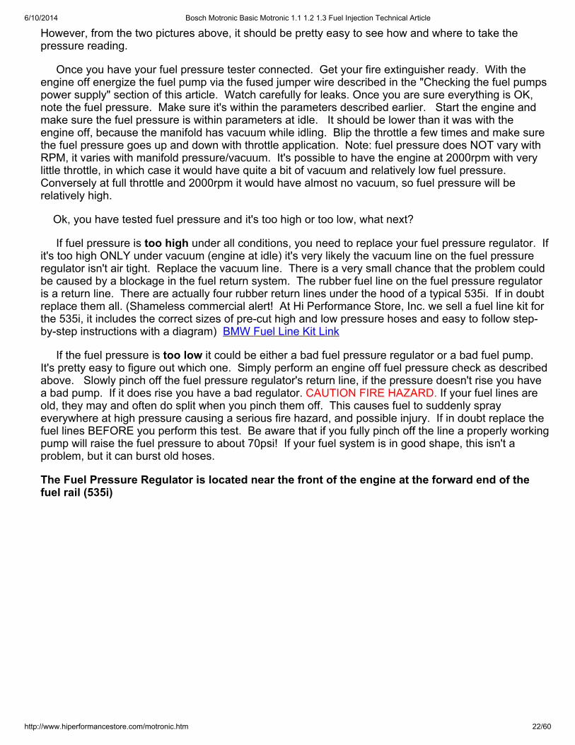
If fuel pressure is too high under all conditions, you need to replace your fuel pressure regulator. Ifit's too high ONLY under vacuum (engine at idle) it's very likely the vacuum line on the fuel pressureregulator isn't air tight. Replace the vacuum line. There is a very small chance that the problem couldbe caused by a blockage in the fuel return system. The rubber fuel line on the fuel pressure regulatoris a return line. There are actually four rubber return lines under the hood of a typical 535i. If in doubtreplace them all. (Shameless commercial alert! At Hi Performance Store, Inc. we sell a fuel line kit forthe 535i, it includes the correct sizes of pre-cut high and low pressure hoses and easy to follow step-by-step instructions with a diagram) BMW Fuel Line Kit Link
If the fuel pressure is too low it could be either a bad fuel pressure regulator or a bad fuel pump. It's pretty easy to figure out which one. Simply perform an engine off fuel pressure check as describedabove. Slowly pinch off the fuel pressure regulator's return line, if the pressure doesn't rise you havea bad pump. If it does rise you have a bad regulator. CAUTION FIRE HAZARD. If your fuel lines areold, they may and often do split when you pinch them off. This causes fuel to suddenly sprayeverywhere at high pressure causing a serious fire hazard, and possible injury. If in doubt replace thefuel lines BEFORE you perform this test. Be aware that if you fully pinch off the line a properly workingpump will raise the fuel pressure to about 70psi! If your fuel system is in good shape, this isn't aproblem, but it can burst old hoses.
The Fuel Pressure Regulator is located near the front of the engine at the forward end of thefuel rail (535i)
6/10/2014 Bosch Motronic Basic Motronic 1.1 1.2 1.3 Fuel Injection Technical Article
http://www.hiperformancestore.com/motronic.htm 23/60
If you don't have a 535i you will have to find your fuel pressure regulator. They all look pretty muchthe same so the picture above should help. On Motronic cars they are almost always located on thefuel rail and have one vacuum line, and one fuel line attached to them.
Step 6, Fuel Injector on and off car checks. If you have been following this article from the start, your car is now free of vacuum leaks, theinjection system powers up properly, the grounds are good and it has good fuel pressure. Next we
need to look at the fuel injectors. *Fuel injectors are another major component of the injection system,and they can cause a wide range of problems including difficult hot or cold starting, irregular idle, lowpower, high emission, poor fuel economy, stalling, and the starts and stalls syndrome. The injectorswork by opening and closing at a rate and duration specified by the Motronic ECU. When open, fuelunder pressure sprays in. The injectors can develop external leaks, they can stick open, stick closed,they can stick a little bit so they don't open and close at the correct rate, they can leak internally, andmost common they can be partially clogged so they don't flow the correct amount of fuel.
A word of caution. Each injector has its own fuel filter. The filter's inlet screen is so fine the holesare not visible to the naked eye! DO NOT put fuel system cleaner or fuel injector cleaner in yourE28's fuel tank. All this will do is wash debris that's been building up for all these years downstreaminto these tiny filters. At least it will tend to clog all the filters equally, and this may actually improverunning if it's masking another fault, however partially clogged injectors will not deliver enough fuel atfull throttle and if knocking occurs as a result you could have serious engine damage. Trust me on thisone, don't use these products on older cars. Well, I guess there is one exception to this. If you aregoing to pull and have your injectors cleaned anyway, it wouldn't hurt to use these products rightbefore you did that. That would clean out the fuel system and since you are having the injector filtersreplaced there won't be any harm.
The bad news is it's not possible to fully test the fuel injectors with them on the car. The good newsis there are a couple checks we can do with them on the car, and these checks are pretty good atfinding some of the more serious possible problems.
First, we need to check the injectors' electrical impedance. Once again you will need to get outyour OHM meter. We do this test first because if the injector fails this test, it's junk and can not be
6/10/2014 Bosch Motronic Basic Motronic 1.1 1.2 1.3 Fuel Injection Technical Article
http://www.hiperformancestore.com/motronic.htm 24/60
fixed. Start by locating the injectors. There will be one per cylinder, meaning on all E28s sold in theU.S. there are six main fuel injectors (there is also a 7th injector called a "cold start valve" which wewill cover later). The injectors are easy to find, they are all attached to the fuel rail so look for the fuelpressure regulator which is attached to the front end of the fuel rail. Follow the rail back until you findall six injectors. Each injector has an electrical connector on it.
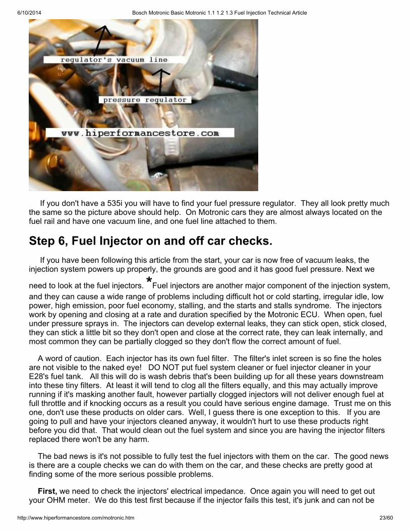
In this picture, my finger is touching cylinder #2's fuel injector. The injector's connector hasbeen removed for clarity.
Remove the injector's electrical connector. Be careful, it's held on with a tiny metal retaining clip. This metal clip must be removed before you pull the connector off or damage to the connector willresult. Use a really small screwdriver to pry the clip away. Don't drop it! Well, you probably will dropone at some point, so have a magnet nearby. (note: some cars have the squeeze to release typemetal clips.) Once the clip is off you can see the injector has a two terminal electrical connection. Weneed to measure the resistance between these two terminals. It should fall within the followingvalues. For the 528e with Motronic 1.1, and all 535i cars resistance should be between 14.5 and 17.5ohms. If you have a 528e with Motronic Basic, or a 633i the values should be between 2 and 3 ohms. Test for these values with your OHM meter, be sure to test for resistance between the terminals on theinjector. DO NOT touch the ohm meter to the wiring harness' connectors. If an injector fails this test,it's junk and must be replaced. Also, don't reinstall those metal clips yet. You will need those to be offthe the next test.
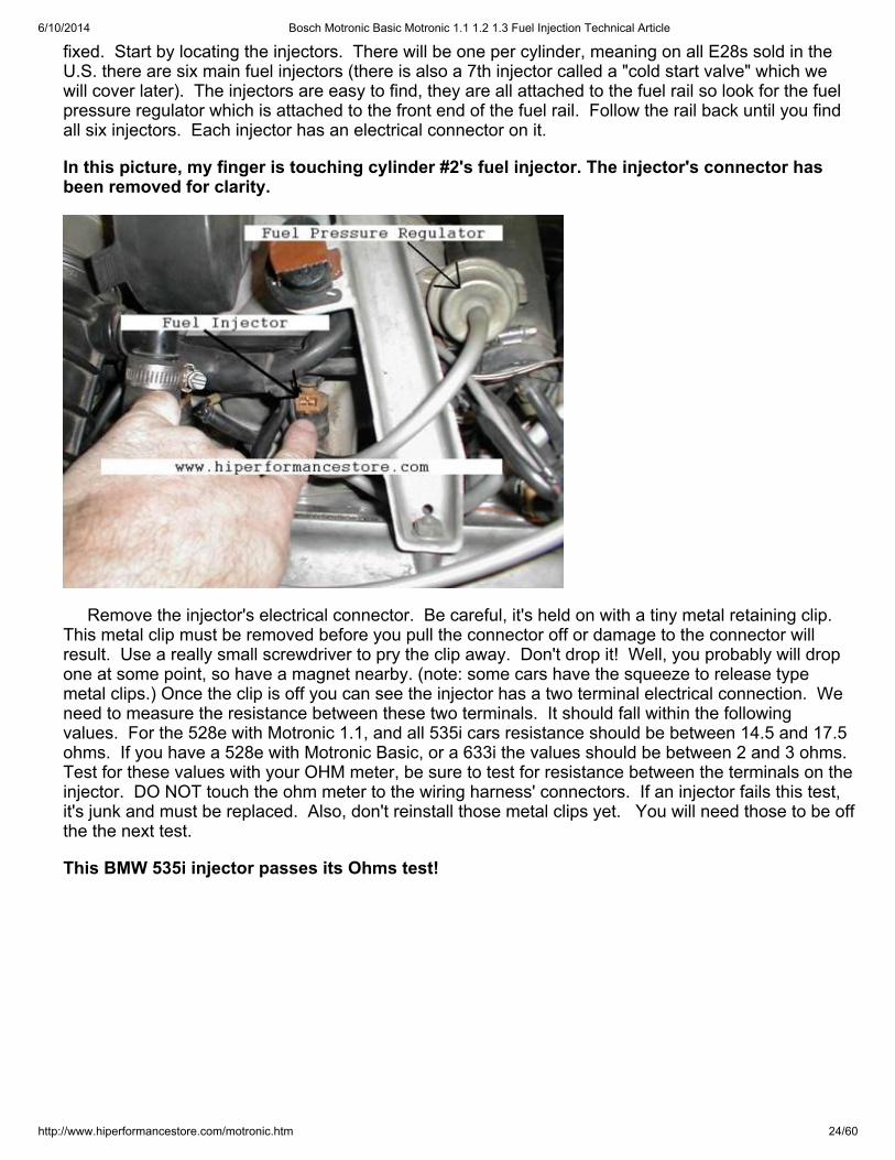
This BMW 535i injector passes its Ohms test!
6/10/2014 Bosch Motronic Basic Motronic 1.1 1.2 1.3 Fuel Injection Technical Article
http://www.hiperformancestore.com/motronic.htm 25/60
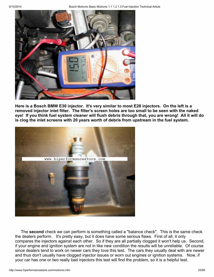
Here is a Bosch BMW E30 injector. It's very similar to most E28 injectors. On the left is aremoved injector inlet filter. The filter's screen holes are too small to be seen with the nakedeye! If you think fuel system cleaner will flush debris through that, you are wrong! All it will dois clog the inlet screens with 20 years worth of debris from upstream in the fuel system.
The second check we can perform is something called a "balance check". This is the same checkthe dealers perform. It's pretty easy, but it does have some serious flaws. First of all, it onlycompares the injectors against each other. So if they are all partially clogged it won't help us. Second,if your engine and ignition system are not in like new condition the results will be unreliable. Of coursesince dealers tend to work on newer cars they love this test. The cars they usually deal with are newerand thus don't usually have clogged injector issues or worn out engines or ignition systems. Now, ifyour car has one or two really bad injectors this test will find the problem, so it is a helpful test.
6/10/2014 Bosch Motronic Basic Motronic 1.1 1.2 1.3 Fuel Injection Technical Article
http://www.hiperformancestore.com/motronic.htm 26/60
To perform a balance check you will need to be able to easily pull off each injector's electricalconnector. That means before you start this test you need to remove each little metal clip securing theinjector's connector. Leave the connector on the injector, without the clip, start the engine and let itfully warm up. Once it's fully warmed up and idling very steadily, remove each injector's connectionone at a time and note the RPM drop. Now in a perfect world the cylinder with the LOWEST RPMdrop is the one with the worst injector. In other words, if the RPM does not drop at all, then it stands toreason that fuel injector is not delivering any fuel. I can't stress enough the flaw in this test is the lackof a perfect world situation on a 20 year old car. It could be the lowest RPM drop is on a cylinder witha really good injector but poor compression, or a weak spark. Heck it could just be time for a new cap,rotor, and spark plugs. This test has one other BIG flaw. It only tests the injector when it's under lowdemand. It's not unusual for an injector to work perfectly at idle but poorly under high demandconditions (i.e., full power, high rpm), which is the way I drive my BMW.
In order to really thoroughly test fuel injectors I am afraid they must be off the car and tested on amachine that can measure their output within the operating ranges of fuel pressure, duration, andRPM.
I offer fuel injector flow checking and overhaul service on thelatest type of machine for BMW owners. I have a fuel injector servicing shop. Ihave the latest flow checking and injector cleaning equipment. Details are at www.okinjectors.com .We overhaul BMW injectors with the correct parts!
If you would like your injectors overhauled I can ultrasonically clean them, replace the filters, pintlecaps, and all seals for a very good price. I very thoroughly check them all all the RPM levels and pulsewidths your injectors will experience on the car. Most shops only check them at idle. I also warrantythe injectors I service for 12 months. I have found that when injectors are serviced by other shops theyoften start to leak about 6 months after the service. This is because the internal seals are delicate andcan be easily damaged by the fluids many shops use to clean and flow check. The correct fluids to testand clean these early injectors are $20 a quart so many shops don't bother to use them. I do, that'swhy I can warranty the injectors I service against external leakage, or any other problems.
After a full overhaul, old BMW injectors usually work like new and our warranted for 12 months.
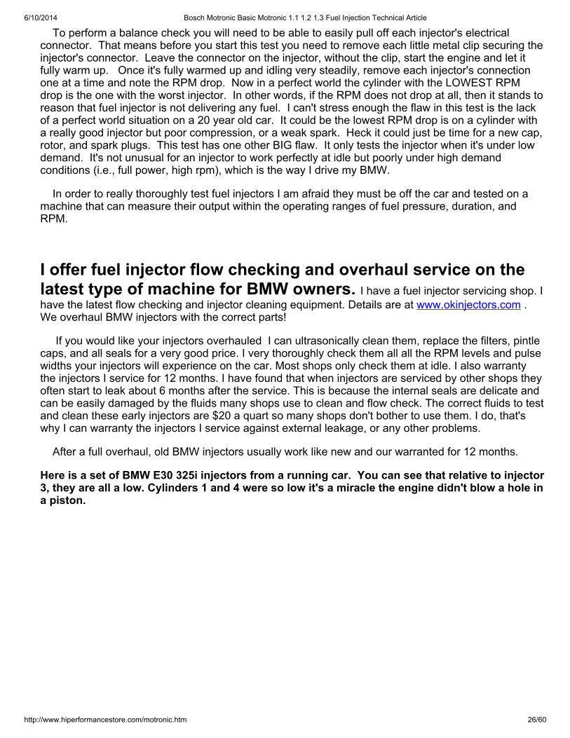
Here is a set of BMW E30 325i injectors from a running car. You can see that relative to injector3, they are all a low. Cylinders 1 and 4 were so low it's a miracle the engine didn't blow a hole ina piston.
6/10/2014 Bosch Motronic Basic Motronic 1.1 1.2 1.3 Fuel Injection Technical Article
http://www.hiperformancestore.com/motronic.htm 27/60
What the picture above doesn't show is that all the injectors were actually low. I just ran the checkuntil the first injector hit 100ccs so the percentage of variation would be easy to see in the picture. After my injector overhaul service this set of injectors was usable again.
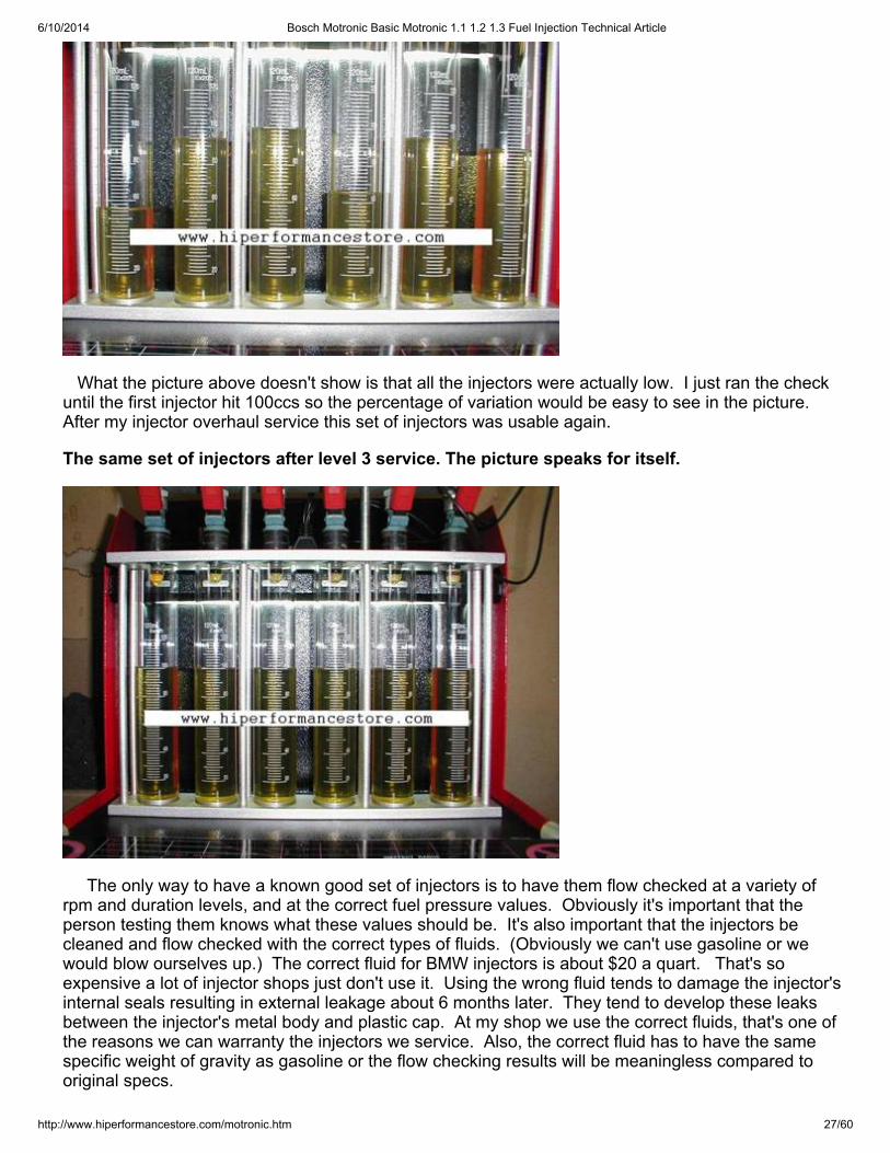
The same set of injectors after level 3 service. The picture speaks for itself.
The only way to have a known good set of injectors is to have them flow checked at a variety ofrpm and duration levels, and at the correct fuel pressure values. Obviously it's important that theperson testing them knows what these values should be. It's also important that the injectors becleaned and flow checked with the correct types of fluids. (Obviously we can't use gasoline or wewould blow ourselves up.) The correct fluid for BMW injectors is about $20 a quart. That's soexpensive a lot of injector shops just don't use it. Using the wrong fluid tends to damage the injector'sinternal seals resulting in external leakage about 6 months later. They tend to develop these leaksbetween the injector's metal body and plastic cap. At my shop we use the correct fluids, that's one ofthe reasons we can warranty the injectors we service. Also, the correct fluid has to have the samespecific weight of gravity as gasoline or the flow checking results will be meaningless compared tooriginal specs.
6/10/2014 Bosch Motronic Basic Motronic 1.1 1.2 1.3 Fuel Injection Technical Article
http://www.hiperformancestore.com/motronic.htm 28/60
New injectors: New Bosch injectors are expensive, but they are high quality. There are various otherbrands that can substitute for the 535's Bosch injectors. These other injectors that will physically fitand are so close in flow rate that they will work. The only drawback is that the Bosch injectors seem tobe more precise. The Bosch injectors are usually within 3% of each other, the other brands tend to bewithin 5% of each other. For serious performance applications I like to flow check a couple dozeninjectors and pick the six that are closest to each other. This normally allows me to get injectors within1%.
Step 7, Coolant Temperature Sensor! The coolant temp sensor is one of my favorite components to test. Probably because it's so easy,and yet, it's such an important device. This device reports the coolant temperature to the MotronicECU. The ECU uses that information to adjust mixture for engine temperature. It richens the mixturewhen cold.
If you are a veteran of working on earlier L-Jetronic systems you probably remember how a badconnection at this sensor would instantly shut off the engine. Well it seems somebody at Boschdecided that wasn't such a good thing because they improved it for the Motronic system. On the E28sif this sensor is disconnected or if the the connection is poor, the engine will still run. It may not start,and it will run poorly, but at least it will run so it's no longer a device that can leave you stranded on I-10, 20 miles outside of Lordsburg, New Mexico.
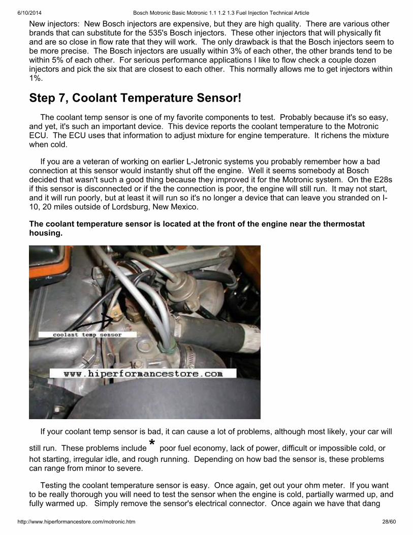
The coolant temperature sensor is located at the front of the engine near the thermostathousing.
If your coolant temp sensor is bad, it can cause a lot of problems, although most likely, your car will
still run. These problems include * poor fuel economy, lack of power, difficult or impossible cold, orhot starting, irregular idle, and rough running. Depending on how bad the sensor is, these problemscan range from minor to severe.
Testing the coolant temperature sensor is easy. Once again, get out your ohm meter. If you wantto be really thorough you will need to test the sensor when the engine is cold, partially warmed up, andfully warmed up. Simply remove the sensor's electrical connector. Once again we have that dang
6/10/2014 Bosch Motronic Basic Motronic 1.1 1.2 1.3 Fuel Injection Technical Article
http://www.hiperformancestore.com/motronic.htm 29/60
metal clip that must be removed first. Here are the resistance values we should see on a good sensor:
On a 528e with Motronic Basic, or a 533i if the coolant temperature is 12F-16F (-9C to -11C)resistance between the two terminals should be 7000-11600 ohms. At a coolant temperature of 66F-70F (19C-21C) it should be 2100-2900 ohms. When the engine is fully warmed up the coolanttemperature should be 174F-178F (79C-81C) and you should have 270-400 ohms of resistance.
If you have a 528e with Motronic 1.1 or a 535i you are looking for a slightly different set of values. With a coolant temperature of 12-16F (-9C to -11C) resistance between the two terminals should be8200-10500 ohms. At a coolant temperature of 66F-70F (19C-21C) it should be 2200-2700 ohms. When the engine is fully warmed up the coolant temperature should be 174F-178F (79C-81C) and youshould have 300-360 ohms of resistance.
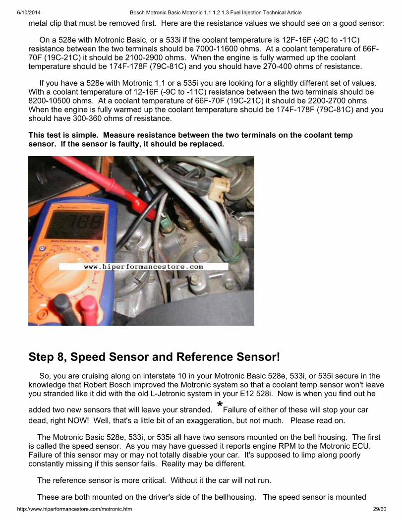
This test is simple. Measure resistance between the two terminals on the coolant tempsensor. If the sensor is faulty, it should be replaced.
Step 8, Speed Sensor and Reference Sensor! So, you are cruising along on interstate 10 in your Motronic Basic 528e, 533i, or 535i secure in theknowledge that Robert Bosch improved the Motronic system so that a coolant temp sensor won't leaveyou stranded like it did with the old L-Jetronic system in your E12 528i. Now is when you find out he
added two new sensors that will leave your stranded. *Failure of either of these will stop your cardead, right NOW! Well, that's a little bit of an exaggeration, but not much. Please read on.
The Motronic Basic 528e, 533i, or 535i all have two sensors mounted on the bell housing. The firstis called the speed sensor. As you may have guessed it reports engine RPM to the Motronic ECU. Failure of this sensor may or may not totally disable your car. It's supposed to limp along poorlyconstantly missing if this sensor fails. Reality may be different.
The reference sensor is more critical. Without it the car will not run.
These are both mounted on the driver's side of the bellhousing. The speed sensor is mounted
6/10/2014 Bosch Motronic Basic Motronic 1.1 1.2 1.3 Fuel Injection Technical Article
http://www.hiperformancestore.com/motronic.htm 30/60
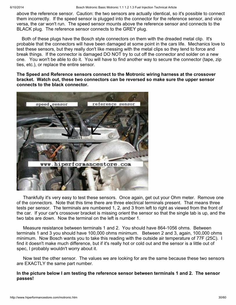
above the reference sensor. Caution: the two sensors are actually identical, so it's possible to connectthem incorrectly. If the speed sensor is plugged into the connector for the reference sensor, and viceversa, the car won't run. The speed sensor mounts above the reference sensor and connects to theBLACK plug. The reference sensor connects to the GREY plug.
Both of these plugs have the Bosch style connectors on them with the dreaded metal clip. It'sprobable that the connectors will have been damaged at some point in the cars life. Mechanics love totest these sensors, but they really don't like messing with the metal clips so they tend to force andbreak things. If the connector is damaged DO NOT try to cut off the connector and solder on a newone. You won't be able to do it. You will have to find another way to secure the connector (tape, zipties, etc.), or replace the entire sensor.
The Speed and Reference sensors connect to the Motronic wiring harness at the crossoverbracket. Watch out, these two connectors can be reversed so make sure the upper sensorconnects to the black connector.
Thankfully it's very easy to test these sensors. Once again, get out your Ohm meter. Remove oneof the connectors. Note that this time there are three electrical terminals present. That means threetests per sensor. The terminals are numbered 1, 2, and 3 from left to right as viewed from the front ofthe car. If your car's crossover bracket is missing orient the sensor so that the single tab is up, and thetwo tabs are down. Now the terminal on the left is number 1.
Measure resistance between terminals 1 and 2. You should have 864-1056 ohms. Betweenterminals 1 and 3 you should have 100,000 ohms minimum. Between 2 and 3, again, 100,000 ohmsminimum. Now Bosch wants you to take this reading with the outside air temperature of 77F (25C). Ifind it doesn't make much difference, but if it's really hot or cold out and the sensor is a little out ofspec, I probably wouldn't worry about it.
Now test the other sensor. The values we are looking for are the same because these two sensorsare EXACTLY the same part number.
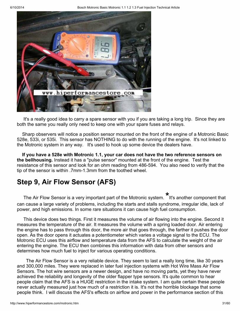
In the picture below I am testing the reference sensor between terminals 1 and 2. The sensorpasses!
6/10/2014 Bosch Motronic Basic Motronic 1.1 1.2 1.3 Fuel Injection Technical Article
http://www.hiperformancestore.com/motronic.htm 31/60
It's a really good idea to carry a spare sensor with you if you are taking a long trip. Since they areboth the same you really only need to keep one with your spare fuses and relays.
Sharp observers will notice a position sensor mounted on the front of the engine of a Motronic Basic528e, 533i, or 535i. This sensor has NOTHING to do with the running of the engine. It's not linked tothe Motronic system in any way. It's used to hook up some device the dealers have.
If you have a 528e with Motronic 1.1, your car does not have the two reference sensors onthe bellhousing. Instead it has a "pulse sensor" mounted at the front of the engine. Test theresistance of this sensor and look for an ohm reading from 486-594. You also need to verify that thetip of the sensor is within .7mm-1.3mm from the toothed wheel.
Step 9, Air Flow Sensor (AFS)
The Air Flow Sensor is a very important part of the Motronic system. *It's another component thatcan cause a large variety of problems, including the starts and stalls syndrome, irregular idle, lack ofpower, and high emissions. In some rare situations it can cause high fuel consumption.
This device does two things. First it measures the volume of air flowing into the engine. Second itmeasures the temperature of the air. It measures the volume with a spring loaded door. Air enteringthe engine has to pass through this door, the more air that goes through, the farther it pushes the dooropen. As the door opens it actuates a potentiometer which varies a voltage signal to the ECU. TheMotronic ECU uses this airflow and temperature data from the AFS to calculate the weight of the airentering the engine. The ECU then combines this information with data from other sensors anddetermines how much fuel to inject for various operating conditions.
The Air Flow Sensor is a very reliable device. They seem to last a really long time, like 30 yearsand 300,000 miles. They were replaced in later fuel injection systems with Hot Wire Mass Air FlowSensors. The hot wire sensors are a newer design, and have no moving parts, yet they have neverachieved the reliability and longevity of the older flapper type sensors. It's quite common to hearpeople claim that the AFS is a HUGE restriction in the intake system. I am quite certain these peoplenever actually measured just how much of a restriction it is. It's not the horrible blockage that somepeople think. I will discuss the AFS's effects on airflow and power in the performance section of this
6/10/2014 Bosch Motronic Basic Motronic 1.1 1.2 1.3 Fuel Injection Technical Article
http://www.hiperformancestore.com/motronic.htm 32/60
article.
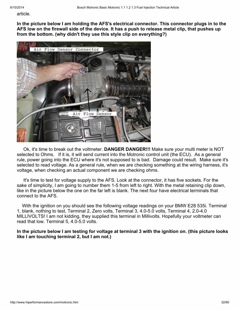
In the picture below I am holding the AFS's electrical connector. This connector plugs in to theAFS low on the firewall side of the device. It has a push to release metal clip, that pushes upfrom the bottom. (why didn't they use this style clip on everything?)
Ok, it's time to break out the voltmeter. DANGER DANGER!!! Make sure your multi meter is NOTselected to Ohms. If it is, it will send current into the Motronic control unit (the ECU). As a generalrule, power going into the ECU where it's not supposed to is bad. Damage could result. Make sure it'sselected to read voltage. As a general rule, when we are checking something at the wiring harness, it'svoltage, when checking an actual component we are checking ohms.
It's time to test for voltage supply to the AFS. Look at the connector, it has five sockets. For thesake of simplicity, I am going to number them 1-5 from left to right. With the metal retaining clip down,like in the picture below the one on the far left is blank. The next four have electrical terminals thatconnect to the AFS.
With the ignition on you should see the following voltage readings on your BMW E28 535i. Terminal1, blank, nothing to test, Terminal 2, Zero volts, Terminal 3, 4.0-5.0 volts, Terminal 4, 2.0-4.0MILLIVOLTS! I am not kidding, they supplied this terminal in Millivolts. Hopefully your voltmeter canread that low. Terminal 5, 4.0-5.0 volts.
In the picture below I am testing for voltage at terminal 3 with the ignition on. (this picture lookslike I am touching terminal 2, but I am not.)
6/10/2014 Bosch Motronic Basic Motronic 1.1 1.2 1.3 Fuel Injection Technical Article
http://www.hiperformancestore.com/motronic.htm 33/60
Hopefully your car passed that voltage supply test. If so, do not put the connector back on yet, wehave more to test. If it did not pass the voltage supply test your problem is most likely in the ECU orthe wiring harness. Double check steps 4 and 5 to make sure the Motronic system is powering up andis grounded. If you still have a problem getting power to the AFS go to step 15.
If your car passed that test, it's time to test the AFS's internal door, and potentiometer. Testing thedoor is simple. Remove the hard plastic elbow that connects the AFS to the air filter box. Reach insidewith your fingers and simply push the door. It should move freely without any strange noises, orbinding. Assuming it does, do not put the elbow back on yet, move on to the electrical test.
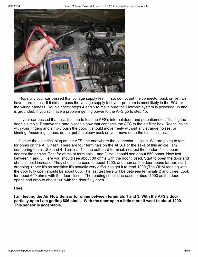
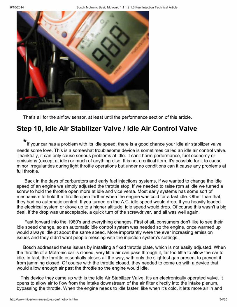
Locate the electrical plug on the AFS, the one where the connector plugs in. We are going to testfor ohms on the AFS itself. There are four terminals on the AFS. For the sake of this article I amnumbering them 1,2,3 and 4. Terminal 1 is the outboard terminal, nearest the fender, 4 is inboardnearest the engine. Test for ohms at terminals 1 and 2. You should see about 550 ohms. Now testbetween 1 and 3. Here you should see about 80 ohms with the door closed. Start to open the door andohms should increase. They should increase to about 1200, and then as the door opens farther, startdropping. (note: It's so sensitive it's actually very difficult to get it to read 1200.)The OHM reading withthe door fully open should be about 600. The last test here will be between terminals 2 and three. Lookfor about 600 ohms with the door closed. The reading should increase to about 1000 as the dooropens and drop to about 100 with the door fully open.
Here,
I am testing the Air Flow Sensor for ohms between terminals 1 and 3. With the AFS's doorpartially open I am getting 886 ohms. With the door open a little more it went to about 1200.This sensor is acceptable.
6/10/2014 Bosch Motronic Basic Motronic 1.1 1.2 1.3 Fuel Injection Technical Article
http://www.hiperformancestore.com/motronic.htm 34/60
That's all for the airflow sensor, at least until the performance section of this article.
Step 10, Idle Air Stabilizer Valve / Idle Air Control Valve
*If your car has a problem with its idle speed, there is a good chance your idle air stabilizer valveneeds some love. This is a somewhat troublesome device is sometimes called an idle air control valve.Thankfully, it can only cause serious problems at idle. It can't harm performance, fuel economy oremissions (except at idle) or much of anything else. It is not a critical item. It's possible for it to causeminor irregularities during light throttle operations but under no conditions can it cause any problems atfull throttle.
Back in the days of carburetors and early fuel injections systems, if we wanted to change the idlespeed of an engine we simply adjusted the throttle stop. If we needed to raise rpm at idle we turned ascrew to hold the throttle open more at idle and vice versa. Most early systems has some sort ofmechanism to hold the throttle open farther when the engine was cold for a fast idle. Other than that,they had no automatic control. If you turned on the A.C. idle speed would drop. If you heavily loadedthe electrical system or drove up to a higher altitude, idle speed would drop. Of course this wasn't a bigdeal, if the drop was unacceptable, a quick turn of the screwdriver, and all was well again.
Fast forward into the 1980's and everything changes. First of all, consumers don't like to see theiridle speed change, so an automatic idle control system was needed so the engine, once warmed upwould always idle at about the same speed. More importantly were the ever increasing emissionissues and they didn't want people messing with the injection system's settings.
Bosch addressed these issues by installing a fixed throttle plate, which is not easily adjusted. Whenthe throttle of a Motronic car is closed, very little air can pass through it, far too little to allow the car toidle. In fact, the throttle essentially closes all the way, with only the slightest gap present to prevent itfrom jamming closed. Of course with the throttle closed, they needed to come up with a device thatwould allow enough air past the throttle so the engine would idle.
This device they came up with is the Idle Air Stabilizer Valve. It's an electronically operated valve. Itopens to allow air to flow from the intake downstream of the air filter directly into the intake plenum,bypassing the throttle. When the engine needs to idle faster, like when it's cold, it lets more air in and
6/10/2014 Bosch Motronic Basic Motronic 1.1 1.2 1.3 Fuel Injection Technical Article
http://www.hiperformancestore.com/motronic.htm 35/60
vice versa.
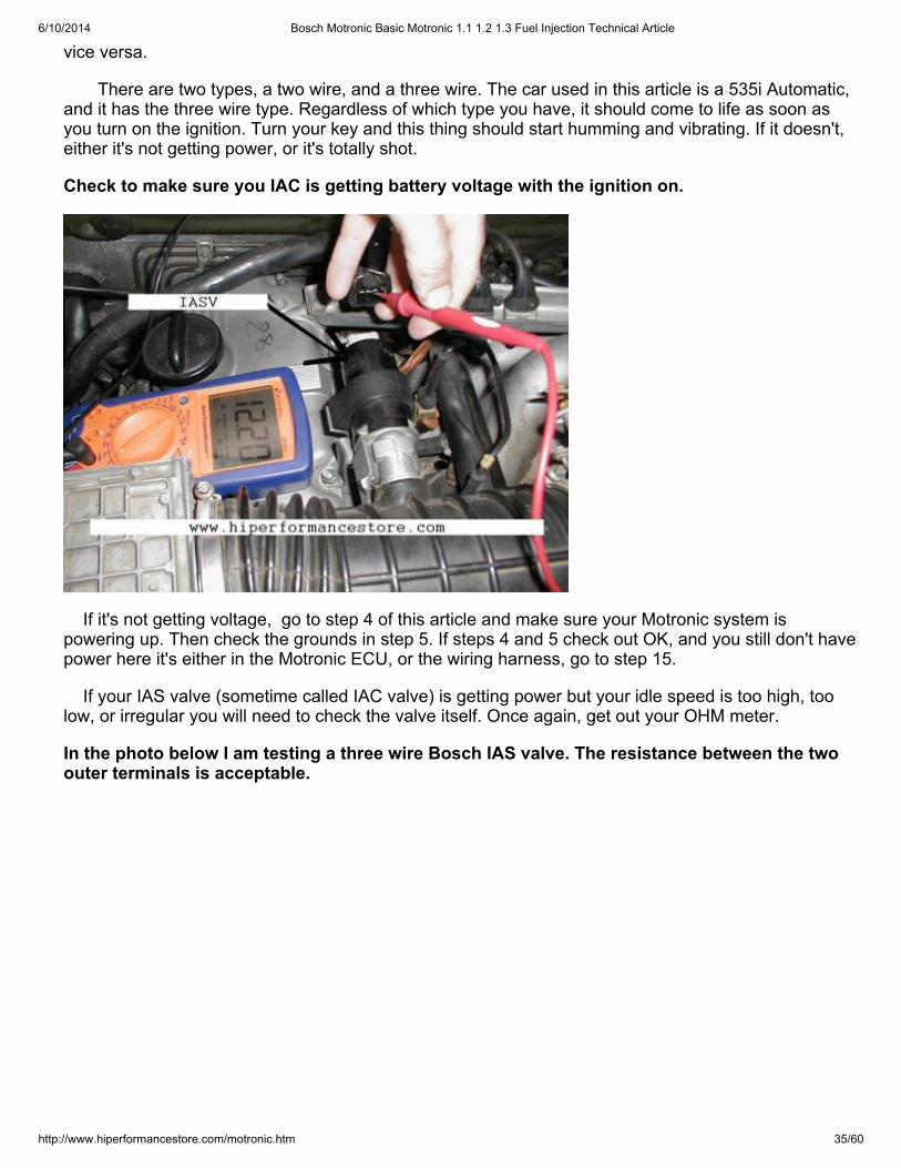
There are two types, a two wire, and a three wire. The car used in this article is a 535i Automatic,and it has the three wire type. Regardless of which type you have, it should come to life as soon asyou turn on the ignition. Turn your key and this thing should start humming and vibrating. If it doesn't,either it's not getting power, or it's totally shot.
Check to make sure you IAC is getting battery voltage with the ignition on.
If it's not getting voltage, go to step 4 of this article and make sure your Motronic system ispowering up. Then check the grounds in step 5. If steps 4 and 5 check out OK, and you still don't havepower here it's either in the Motronic ECU, or the wiring harness, go to step 15.
If your IAS valve (sometime called IAC valve) is getting power but your idle speed is too high, toolow, or irregular you will need to check the valve itself. Once again, get out your OHM meter.
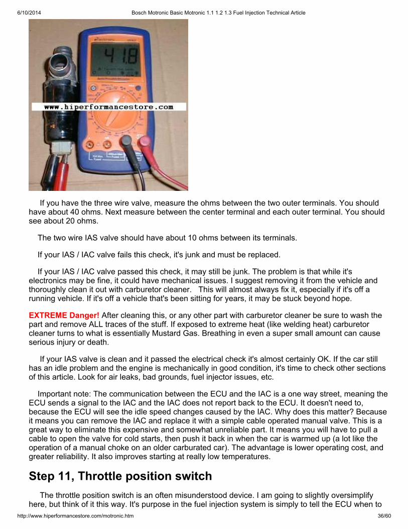
In the photo below I am testing a three wire Bosch IAS valve. The resistance between the twoouter terminals is acceptable.
6/10/2014 Bosch Motronic Basic Motronic 1.1 1.2 1.3 Fuel Injection Technical Article
http://www.hiperformancestore.com/motronic.htm 36/60
If you have the three wire valve, measure the ohms between the two outer terminals. You shouldhave about 40 ohms. Next measure between the center terminal and each outer terminal. You shouldsee about 20 ohms.
The two wire IAS valve should have about 10 ohms between its terminals.
If your IAS / IAC valve fails this check, it's junk and must be replaced.
If your IAS / IAC valve passed this check, it may still be junk. The problem is that while it'selectronics may be fine, it could have mechanical issues. I suggest removing it from the vehicle andthoroughly clean it out with carburetor cleaner. This will almost always fix it, especially if it's off arunning vehicle. If it's off a vehicle that's been sitting for years, it may be stuck beyond hope.
EXTREME Danger! After cleaning this, or any other part with carburetor cleaner be sure to wash thepart and remove ALL traces of the stuff. If exposed to extreme heat (like welding heat) carburetorcleaner turns to what is essentially Mustard Gas. Breathing in even a super small amount can causeserious injury or death.
If your IAS valve is clean and it passed the electrical check it's almost certainly OK. If the car stillhas an idle problem and the engine is mechanically in good condition, it's time to check other sectionsof this article. Look for air leaks, bad grounds, fuel injector issues, etc.
Important note: The communication between the ECU and the IAC is a one way street, meaning theECU sends a signal to the IAC and the IAC does not report back to the ECU. It doesn't need to,because the ECU will see the idle speed changes caused by the IAC. Why does this matter? Becauseit means you can remove the IAC and replace it with a simple cable operated manual valve. This is agreat way to eliminate this expensive and somewhat unreliable part. It means you will have to pull acable to open the valve for cold starts, then push it back in when the car is warmed up (a lot like theoperation of a manual choke on an older carburated car). The advantage is lower operating cost, andgreater reliability. It also improves starting at really low temperatures.
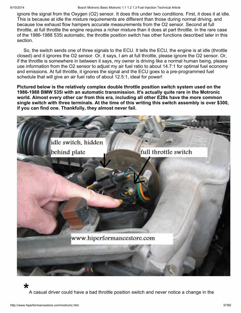
Step 11, Throttle position switch The throttle position switch is an often misunderstood device. I am going to slightly oversimplifyhere, but think of it this way. It's purpose in the fuel injection system is simply to tell the ECU when to
6/10/2014 Bosch Motronic Basic Motronic 1.1 1.2 1.3 Fuel Injection Technical Article
http://www.hiperformancestore.com/motronic.htm 37/60
ignore the signal from the Oxygen (O2) sensor. It does this under two conditions. First, it does it at idle.This is because at idle the mixture requirements are different than those during normal driving, andbecause low exhaust flow hampers accurate measurements from the O2 sensor. Second at fullthrottle, at full throttle the engine requires a richer mixture than it does at part throttle. In the rare caseof the 1986-1988 535i automatic, the throttle position switch has other functions described later in thissection.
So, the switch sends one of three signals to the ECU. It tells the ECU, the engine is at idle (throttleclosed) and it ignores the O2 sensor. Or, it says, I am at full throttle, please ignore the O2 sensor. Or,if the throttle is somewhere in between it says, my owner is driving like a normal human being, pleaseuse information from the O2 sensor to adjust my air fuel ratio to about 14.7:1 for optimal fuel economyand emissions. At full throttle, it ignores the signal and the ECU goes to a pre-programmed fuelschedule that will give an air fuel ratio of about 12.5:1, ideal for power!
Pictured below is the relatively complex double throttle position switch system used on the1986-1988 BMW 535i with an automatic transmission. It's actually quite rare in the Motronicworld. Almost every other car from this era, including all other E28s have the more commonsingle switch with three terminals. At the time of this writing this switch assembly is over $300,if you can find one. Thankfully, they almost never fail.
*A casual driver could have a bad throttle position switch and never notice a change in the
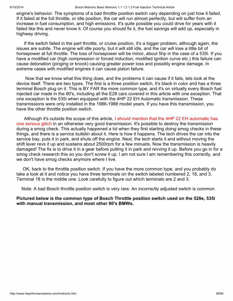
6/10/2014 Bosch Motronic Basic Motronic 1.1 1.2 1.3 Fuel Injection Technical Article
http://www.hiperformancestore.com/motronic.htm 38/60
engine's behavior. The symptoms of a bad throttle position switch vary depending on just how it failed.If it failed at the full throttle, or idle position, the car will run almost perfectly, but will suffer from anincrease in fuel consumption, and high emissions. It's quite possible you could drive for years with itfailed like this and never know it. Of course you should fix it, the fuel savings will add up, especially inhighway driving.
If the switch failed in the part throttle, or cruise position, it's a bigger problem, although again, theissues are subtle. The engine will idle poorly, but it will still idle, and the car will lose a little bit ofhorsepower at full throttle. The loss of horsepower will be minor, about 5hp in the case of a 535i. If youhave a modified car (high compression or forced induction, modified ignition curve etc.) this failure cancause detonation (pinging or knock) causing greater power loss and possibly engine damage. Inextreme cases with modified engines it can cause piston failure.
Now that we know what this thing does, and the problems it can cause if it fails, lets look at thedevice itself. There are two types. The first is a three position switch, it's black in color and has a threeterminal Bosch plug on it. This is BY FAR the more common type, and it's on virtually every Bosch fuelinjected car made in the 80's, including all the E28 cars covered in this article with one exception. Thatone exception is the 535i when equipped with the 4HP 22 EH Automatic transmission. Thesetransmissions were only installed in the 1986-1988 model years. If you have this transmission, youhave the other throttle position switch.
Although it's outside the scope of this article, I should mention that the 4HP 22 EH automatic hasone serious glitch in an otherwise very good transmission. It's possible to destroy the transmissionduring a smog check. This actually happened a lot when they first starting doing smog checks in thesethings, and there is a service bulletin about it. Here is how it happens. The tech drives the car into theservice bay, puts it in park, and shuts off the engine. Next, the tech starts it and without moving theshift lever revs it up and sustains about 2500rpm for a few minuets. Now the transmission is heavilydamaged! The fix is to drive it in a gear before putting it in park and revving it up. Before you go in for asmog check research this so you don't screw it up. I am not sure I am remembering this correctly, andwe don't have smog checks anymore where I live.
OK, back to the throttle position switch. If you have the more common type, and you probably dotake a look at it and notice you have three terminals on the switch labeled numbered 2, 18, and 3.Terminal 18 is the middle one. Look carefully to figure out which terminals are 2 and 3.
Note: A bad Bosch throttle position switch is very rare. An incorrectly adjusted switch is common.
Pictured below is the common type of Bosch Throttle position switch used on the 528e, 535iwith manual transmission, and most other 80's BMWs.
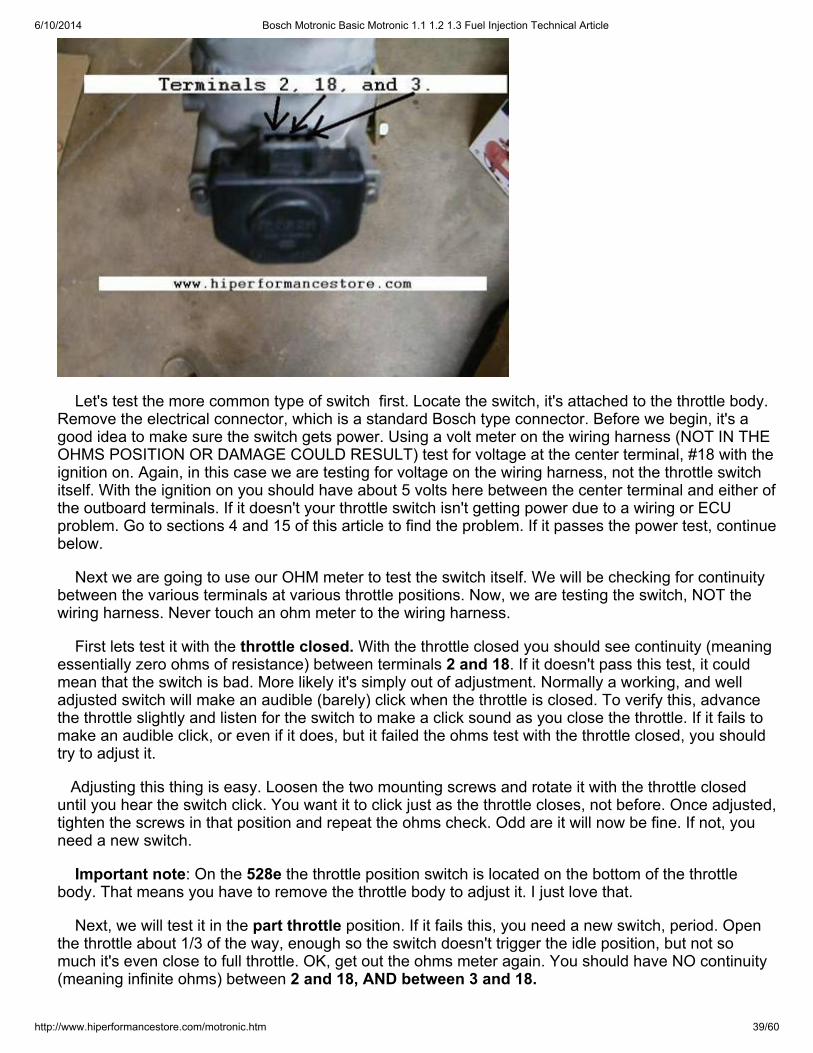
6/10/2014 Bosch Motronic Basic Motronic 1.1 1.2 1.3 Fuel Injection Technical Article
http://www.hiperformancestore.com/motronic.htm 39/60
Let's test the more common type of switch first. Locate the switch, it's attached to the throttle body.Remove the electrical connector, which is a standard Bosch type connector. Before we begin, it's agood idea to make sure the switch gets power. Using a volt meter on the wiring harness (NOT IN THEOHMS POSITION OR DAMAGE COULD RESULT) test for voltage at the center terminal, #18 with theignition on. Again, in this case we are testing for voltage on the wiring harness, not the throttle switchitself. With the ignition on you should have about 5 volts here between the center terminal and either ofthe outboard terminals. If it doesn't your throttle switch isn't getting power due to a wiring or ECUproblem. Go to sections 4 and 15 of this article to find the problem. If it passes the power test, continuebelow.
Next we are going to use our OHM meter to test the switch itself. We will be checking for continuitybetween the various terminals at various throttle positions. Now, we are testing the switch, NOT thewiring harness. Never touch an ohm meter to the wiring harness.
First lets test it with the throttle closed. With the throttle closed you should see continuity (meaningessentially zero ohms of resistance) between terminals 2 and 18. If it doesn't pass this test, it couldmean that the switch is bad. More likely it's simply out of adjustment. Normally a working, and welladjusted switch will make an audible (barely) click when the throttle is closed. To verify this, advancethe throttle slightly and listen for the switch to make a click sound as you close the throttle. If it fails tomake an audible click, or even if it does, but it failed the ohms test with the throttle closed, you shouldtry to adjust it.
Adjusting this thing is easy. Loosen the two mounting screws and rotate it with the throttle closeduntil you hear the switch click. You want it to click just as the throttle closes, not before. Once adjusted,tighten the screws in that position and repeat the ohms check. Odd are it will now be fine. If not, youneed a new switch.
Important note: On the 528e the throttle position switch is located on the bottom of the throttlebody. That means you have to remove the throttle body to adjust it. I just love that.
Next, we will test it in the part throttle position. If it fails this, you need a new switch, period. Openthe throttle about 1/3 of the way, enough so the switch doesn't trigger the idle position, but not somuch it's even close to full throttle. OK, get out the ohms meter again. You should have NO continuity(meaning infinite ohms) between 2 and 18, AND between 3 and 18.
6/10/2014 Bosch Motronic Basic Motronic 1.1 1.2 1.3 Fuel Injection Technical Article
http://www.hiperformancestore.com/motronic.htm 40/60
Last, we need to check full throttle. I know this is the most important position for the enthusiast. It'salso the easiest to check. With the throttle fully open, make sure you have continuity (essentially zeroohms) between terminals 3 and 18. If you don't, and the switch is even close to correctly adjusted, theswitch is junk.
1986-1988 535i Automatic
Ok, lets suppose, that like me, you have a daughter that insisted on having an E28 535i with anautomatic transmission, and you caved in. Don't fear, it's still a much cooler car than those her friendsdrive, and the throttle position switch isn't too bad. The switch looks totally different from the type in theother E28s. It's under a big round rubber covering located on the throttle body towards the front of thecar. This switch is actually two separate switches, one for the idle position, and one for full throttle. Ifneither is engaged, the ECU assumes you are in cruise. This switch does essentially the same thingas the other type, but it communicates in a different way. It sends a full throttle signal to the automatictransmission control unit (located in the dash near the headlight switch). That unit then sends a signalto the ECU saying "full throttle". I don't want to turn this into a transmission article, but know that if yourBMW automatic is shifting hard, won't upshift when it should or has various other issues, it could bethis switch!
With the cover off look at the switch assembly and you will see that it's actually two switches. As youface the switches from the front of the car, the switch on your right (driver's side of the car) is the fullthrottle switch, and the other is the idle switch. Caution, this is correct, various automotive manualshave this backwards!
To test the idle switch unplug the connectors (each terminal has its own connector) and measurethe resistance between the two terminals on the SWITCH side of the connector. With the throttle atidle, you should have continuity (essentially zero ohms) between the two terminals. Advance thethrottle and once it's off idle by any significant amount you should have NO continuity, or infinite ohms.This is actually a tough test to do. I had to use a very long probe to reach that back connector. It's alsotough to get those connectors on and off. I did it, and took a picture of it for this article and accidentallyerased it. So the picture I have isn't the actual test.
The position of the sensor can be adjusted, so if it doesn't test correctly play with the adjustmentbefore you buy a new switch. To adjust it, loosen the mounting screws and rotate the switch. With thethrottle at idle rotate the switch until it clicks. It should click as the throttle reaches idle or just barelybefore. This switch almost never fails or gets out of adjustment so it's not likely to be a problem.
The picture below gives a good idea of what a good test of the idle switch should look like withthe throttle at idle. Be sure to disconnect the switch before you do this test to avoid the risk ofdamage to the ECU.
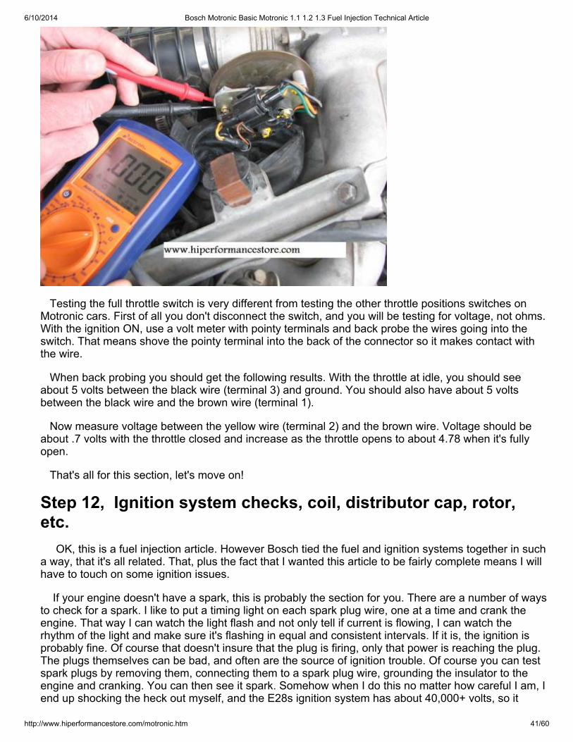
6/10/2014 Bosch Motronic Basic Motronic 1.1 1.2 1.3 Fuel Injection Technical Article
http://www.hiperformancestore.com/motronic.htm 41/60
Testing the full throttle switch is very different from testing the other throttle positions switches onMotronic cars. First of all you don't disconnect the switch, and you will be testing for voltage, not ohms.With the ignition ON, use a volt meter with pointy terminals and back probe the wires going into theswitch. That means shove the pointy terminal into the back of the connector so it makes contact withthe wire.
When back probing you should get the following results. With the throttle at idle, you should seeabout 5 volts between the black wire (terminal 3) and ground. You should also have about 5 voltsbetween the black wire and the brown wire (terminal 1).
Now measure voltage between the yellow wire (terminal 2) and the brown wire. Voltage should beabout .7 volts with the throttle closed and increase as the throttle opens to about 4.78 when it's fullyopen.
That's all for this section, let's move on!
Step 12, Ignition system checks, coil, distributor cap, rotor,etc. OK, this is a fuel injection article. However Bosch tied the fuel and ignition systems together in sucha way, that it's all related. That, plus the fact that I wanted this article to be fairly complete means I willhave to touch on some ignition issues.
If your engine doesn't have a spark, this is probably the section for you. There are a number of waysto check for a spark. I like to put a timing light on each spark plug wire, one at a time and crank theengine. That way I can watch the light flash and not only tell if current is flowing, I can watch therhythm of the light and make sure it's flashing in equal and consistent intervals. If it is, the ignition isprobably fine. Of course that doesn't insure that the plug is firing, only that power is reaching the plug.The plugs themselves can be bad, and often are the source of ignition trouble. Of course you can testspark plugs by removing them, connecting them to a spark plug wire, grounding the insulator to theengine and cranking. You can then see it spark. Somehow when I do this no matter how careful I am, Iend up shocking the heck out myself, and the E28s ignition system has about 40,000+ volts, so it
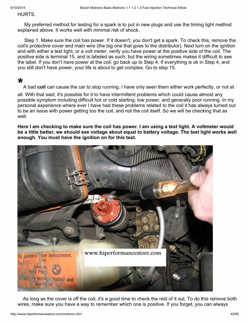
6/10/2014 Bosch Motronic Basic Motronic 1.1 1.2 1.3 Fuel Injection Technical Article
http://www.hiperformancestore.com/motronic.htm 42/60
HURTS.
My preferred method for testing for a spark is to put in new plugs and use the timing light methodexplained above. It works well with minimal risk of shock.
Step 1. Make sure the coil has power. If it doesn't, you don't get a spark. To check this, remove thecoil's protective cover and main wire (the big one that goes to the distributor). Next turn on the ignitionand with either a test light, or a volt meter, verify you have power at the positive side of the coil. Thepositive side is terminal 15, and is labeled as such, but the wiring sometimes makes it difficult to seethe label. If you don't have power at the coil, go back up to Step 4. If everything is ok in Step 4, andyou still don't have power, your life is about to get complex. Go to step 15.
*A bad coil can cause the car to stop running. I have only seen them either work perfectly, or not atall. With that said, it's possible for it to have intermittent problems which could cause almost anypossible symptom including difficult hot or cold starting, low power, and generally poor running. In mypersonal experience where ever I have had these problems related to the coil it has always turned outto be an issue with power getting too the coil, and not the coil itself. So we will be checking that aswell.
Here I am checking to make sure the coil has power. I am using a test light. A voltmeter wouldbe a little better, we should see voltage about equal to battery voltage. The test light works wellenough. You must have the ignition on for this test.
As long as the cover is off the coil, it's a good time to check the rest of it out. To do this remove bothwires, make sure you have a way to remember which one is positive. If you forget, you can always
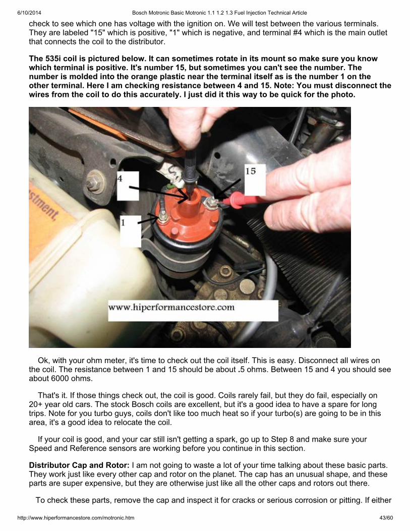
6/10/2014 Bosch Motronic Basic Motronic 1.1 1.2 1.3 Fuel Injection Technical Article
http://www.hiperformancestore.com/motronic.htm 43/60
check to see which one has voltage with the ignition on. We will test between the various terminals.They are labeled "15" which is positive, "1" which is negative, and terminal #4 which is the main outletthat connects the coil to the distributor.
The 535i coil is pictured below. It can sometimes rotate in its mount so make sure you knowwhich terminal is positive. It's number 15, but sometimes you can't see the number. Thenumber is molded into the orange plastic near the terminal itself as is the number 1 on theother terminal. Here I am checking resistance between 4 and 15. Note: You must disconnect thewires from the coil to do this accurately. I just did it this way to be quick for the photo.
Ok, with your ohm meter, it's time to check out the coil itself. This is easy. Disconnect all wires onthe coil. The resistance between 1 and 15 should be about .5 ohms. Between 15 and 4 you should seeabout 6000 ohms.
That's it. If those things check out, the coil is good. Coils rarely fail, but they do fail, especially on20+ year old cars. The stock Bosch coils are excellent, but it's a good idea to have a spare for longtrips. Note for you turbo guys, coils don't like too much heat so if your turbo(s) are going to be in thisarea, it's a good idea to relocate the coil.
If your coil is good, and your car still isn't getting a spark, go up to Step 8 and make sure yourSpeed and Reference sensors are working before you continue in this section.
Distributor Cap and Rotor: I am not going to waste a lot of your time talking about these basic parts.They work just like every other cap and rotor on the planet. The cap has an unusual shape, and theseparts are super expensive, but they are otherwise just like all the other caps and rotors out there.
To check these parts, remove the cap and inspect it for cracks or serious corrosion or pitting. If either
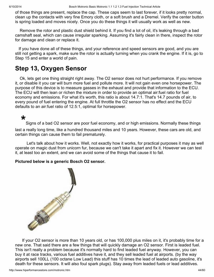
6/10/2014 Bosch Motronic Basic Motronic 1.1 1.2 1.3 Fuel Injection Technical Article
http://www.hiperformancestore.com/motronic.htm 44/60
of those things are present, replace the cap. These caps seem to last forever, if it looks pretty normal,clean up the contacts with very fine Emory cloth, or a soft brush and a Dremel. Verify the center buttonis spring loaded and moves nicely. Once you do these things it will usually work as well as new.
Remove the rotor and plastic dust shield behind it. If you find a lot of oil, it's leaking through a badcamshaft seal, which can cause irregular sparking. Assuming it's fairly clean in there, inspect the rotorfor damage and clean or replace it.
If you have done all of these things, and your reference and speed sensors are good, and you arestill not getting a spark, make sure the rotor is actually turning when you crank the engine. If it is, go toStep 15 and enter a world of pain.
Step 13, Oxygen Sensor Ok, lets get one thing straight right away. The O2 sensor does not hurt performance. If you removeit, or disable it you car will burn more fuel and pollute more. It will not gain even one horsepower. Thepurpose of this device is to measure gasses in the exhaust and provide that information to the ECU.The ECU will then lean or richen the mixture in order to provide an optimal air:fuel ratio for fueleconomy and emissions. For what it's worth, this ratio is about 14.7:1. That's 14.7 pounds of air, toevery pound of fuel entering the engine. At full throttle the O2 sensor has no effect and the ECUdefaults to an air:fuel ratio of 12.5:1, optimal for horsepower.
*Signs of a bad O2 sensor are poor fuel economy, and or high emissions. Normally these thingslast a really long time, like a hundred thousand miles and 10 years. However, these cars are old, andcertain things can cause them to fail prematurely.
Let's talk about how it works. Well, not exactly how it works, for practical purposes it may as welloperate on magic dust from unicorn fur, because we can't take it apart and fix it. However we can testit, at least too an extent, and we can avoid some of the things that cause it to fail.
Pictured below is a generic Bosch O2 sensor.
If your O2 sensor is more than 10 years old, or has 100,000 plus miles on it, it's probably time for anew one. That said there are a few things that will quickly damage an O2 sensor. First is leaded fuel.This isn't really a problem because it's normally hard to find leaded fuel anyway. However, you canbuy it at race tracks, various fuel additives have it, and they sell leaded fuel at airports. (by the wayairports sell 100LL (100 octane Low Lead) this stuff has 10 times the lead of leaded auto gasoline, it'sdeath for these sensors. It will also foul spark plugs). Stay away from leaded fuels or lead additives.
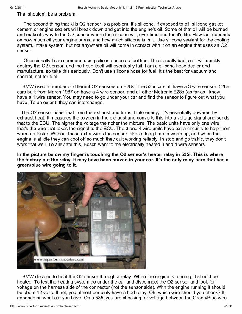
6/10/2014 Bosch Motronic Basic Motronic 1.1 1.2 1.3 Fuel Injection Technical Article
http://www.hiperformancestore.com/motronic.htm 45/60
That shouldn't be a problem.
The second thing that kills O2 sensor is a problem. It's silicone. If exposed to oil, silicone gasketcement or engine sealers will break down and get into the engine's oil. Some of that oil will be burnedand make its way to the O2 sensor where the silicone will, over time shorten it's life. How fast dependson how much oil your engine burns, and how much silicone is in it. Use silicone sealant for the coolingsystem, intake system, but not anywhere oil will come in contact with it on an engine that uses an O2sensor.
Occasionally I see someone using silicone hose as fuel line. This is really bad, as it will quicklydestroy the O2 sensor, and the hose itself will eventually fail. I am a silicone hose dealer andmanufacture, so take this seriously. Don't use silicone hose for fuel. It's the best for vacuum andcoolant, not for fuel.
BMW used a number of different O2 sensors on E28s. The 535i cars all have a 3 wire sensor. 528ecars built from March 1987 on have a 4 wire sensor, and all other Motronic E28s (as far as I know)have a 1 wire sensor. You may need to go under your car and find the sensor to figure out what youhave. To an extent, they can interchange.
The O2 sensor uses heat from the exhaust and turns it into energy. It's essentially powered byexhaust heat. It measures the oxygen in the exhaust and converts this into a voltage signal and sendsthat to the ECU. The higher the voltage the richer the mixture. The basic units have only one wire,that's the wire that takes the signal to the ECU. The 3 and 4 wire units have extra circuitry to help themwarm up faster. Without these extra wires the sensor takes a long time to warm up, and when theengine is at idle they can cool off so much they quit working reliably. In stop and go traffic, they don'twork that well. To alleviate this, Bosch went to the electrically heated 3 and 4 wire sensors.
In the picture below my finger is touching the O2 sensor's heater relay in 535i. This is wherethe factory put the relay. It may have been moved in your car. It's the only relay here that has agreen/blue wire going to it.
BMW decided to heat the O2 sensor through a relay. When the engine is running, it should beheated. To test the heating system go under the car and disconnect the O2 sensor and look forvoltage on the harness side of the connector (not the sensor side). With the engine running it shouldbe about 12 volts. If not, you almost certainly have a bad relay. Oh, which wire should you check? Itdepends on what car you have. On a 535i you are checking for voltage between the Green/Blue wire
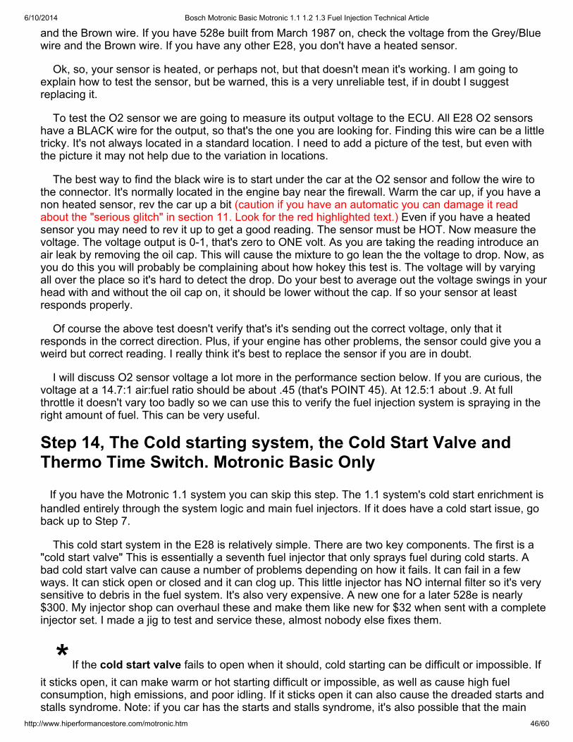
6/10/2014 Bosch Motronic Basic Motronic 1.1 1.2 1.3 Fuel Injection Technical Article
http://www.hiperformancestore.com/motronic.htm 46/60
and the Brown wire. If you have 528e built from March 1987 on, check the voltage from the Grey/Bluewire and the Brown wire. If you have any other E28, you don't have a heated sensor.
Ok, so, your sensor is heated, or perhaps not, but that doesn't mean it's working. I am going toexplain how to test the sensor, but be warned, this is a very unreliable test, if in doubt I suggestreplacing it.
To test the O2 sensor we are going to measure its output voltage to the ECU. All E28 O2 sensorshave a BLACK wire for the output, so that's the one you are looking for. Finding this wire can be a littletricky. It's not always located in a standard location. I need to add a picture of the test, but even withthe picture it may not help due to the variation in locations.
The best way to find the black wire is to start under the car at the O2 sensor and follow the wire tothe connector. It's normally located in the engine bay near the firewall. Warm the car up, if you have anon heated sensor, rev the car up a bit (caution if you have an automatic you can damage it readabout the "serious glitch" in section 11. Look for the red highlighted text.) Even if you have a heatedsensor you may need to rev it up to get a good reading. The sensor must be HOT. Now measure thevoltage. The voltage output is 0-1, that's zero to ONE volt. As you are taking the reading introduce anair leak by removing the oil cap. This will cause the mixture to go lean the the voltage to drop. Now, asyou do this you will probably be complaining about how hokey this test is. The voltage will by varyingall over the place so it's hard to detect the drop. Do your best to average out the voltage swings in yourhead with and without the oil cap on, it should be lower without the cap. If so your sensor at leastresponds properly.
Of course the above test doesn't verify that's it's sending out the correct voltage, only that itresponds in the correct direction. Plus, if your engine has other problems, the sensor could give you aweird but correct reading. I really think it's best to replace the sensor if you are in doubt.
I will discuss O2 sensor voltage a lot more in the performance section below. If you are curious, thevoltage at a 14.7:1 air:fuel ratio should be about .45 (that's POINT 45). At 12.5:1 about .9. At fullthrottle it doesn't vary too badly so we can use this to verify the fuel injection system is spraying in theright amount of fuel. This can be very useful.
Step 14, The Cold starting system, the Cold Start Valve andThermo Time Switch. Motronic Basic Only
If you have the Motronic 1.1 system you can skip this step. The 1.1 system's cold start enrichment ishandled entirely through the system logic and main fuel injectors. If it does have a cold start issue, goback up to Step 7.
This cold start system in the E28 is relatively simple. There are two key components. The first is a"cold start valve" This is essentially a seventh fuel injector that only sprays fuel during cold starts. Abad cold start valve can cause a number of problems depending on how it fails. It can fail in a fewways. It can stick open or closed and it can clog up. This little injector has NO internal filter so it's verysensitive to debris in the fuel system. It's also very expensive. A new one for a later 528e is nearly$300. My injector shop can overhaul these and make them like new for $32 when sent with a completeinjector set. I made a jig to test and service these, almost nobody else fixes them.
* If the cold start valve fails to open when it should, cold starting can be difficult or impossible. Ifit sticks open, it can make warm or hot starting difficult or impossible, as well as cause high fuelconsumption, high emissions, and poor idling. If it sticks open it can also cause the dreaded starts andstalls syndrome. Note: if you car has the starts and stalls syndrome, it's also possible that the main
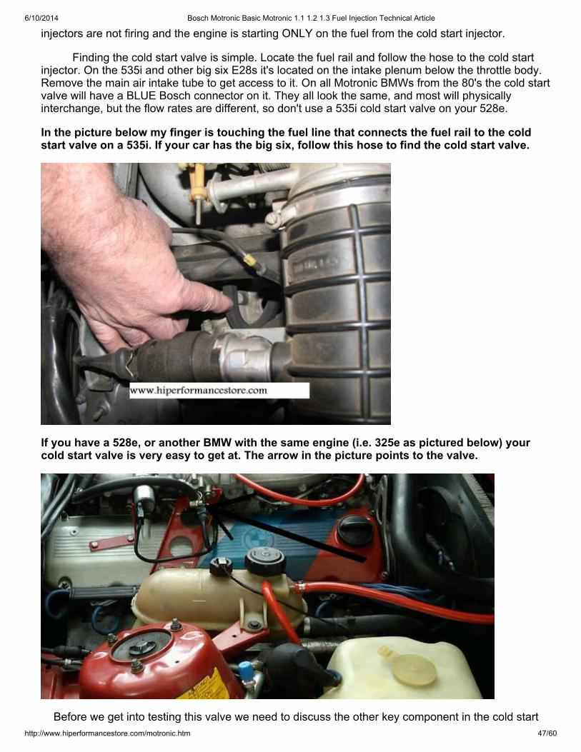
6/10/2014 Bosch Motronic Basic Motronic 1.1 1.2 1.3 Fuel Injection Technical Article
http://www.hiperformancestore.com/motronic.htm 47/60
injectors are not firing and the engine is starting ONLY on the fuel from the cold start injector.
Finding the cold start valve is simple. Locate the fuel rail and follow the hose to the cold startinjector. On the 535i and other big six E28s it's located on the intake plenum below the throttle body.Remove the main air intake tube to get access to it. On all Motronic BMWs from the 80's the cold startvalve will have a BLUE Bosch connector on it. They all look the same, and most will physicallyinterchange, but the flow rates are different, so don't use a 535i cold start valve on your 528e.
In the picture below my finger is touching the fuel line that connects the fuel rail to the coldstart valve on a 535i. If your car has the big six, follow this hose to find the cold start valve.
If you have a 528e, or another BMW with the same engine (i.e. 325e as pictured below) yourcold start valve is very easy to get at. The arrow in the picture points to the valve.
Before we get into testing this valve we need to discuss the other key component in the cold start
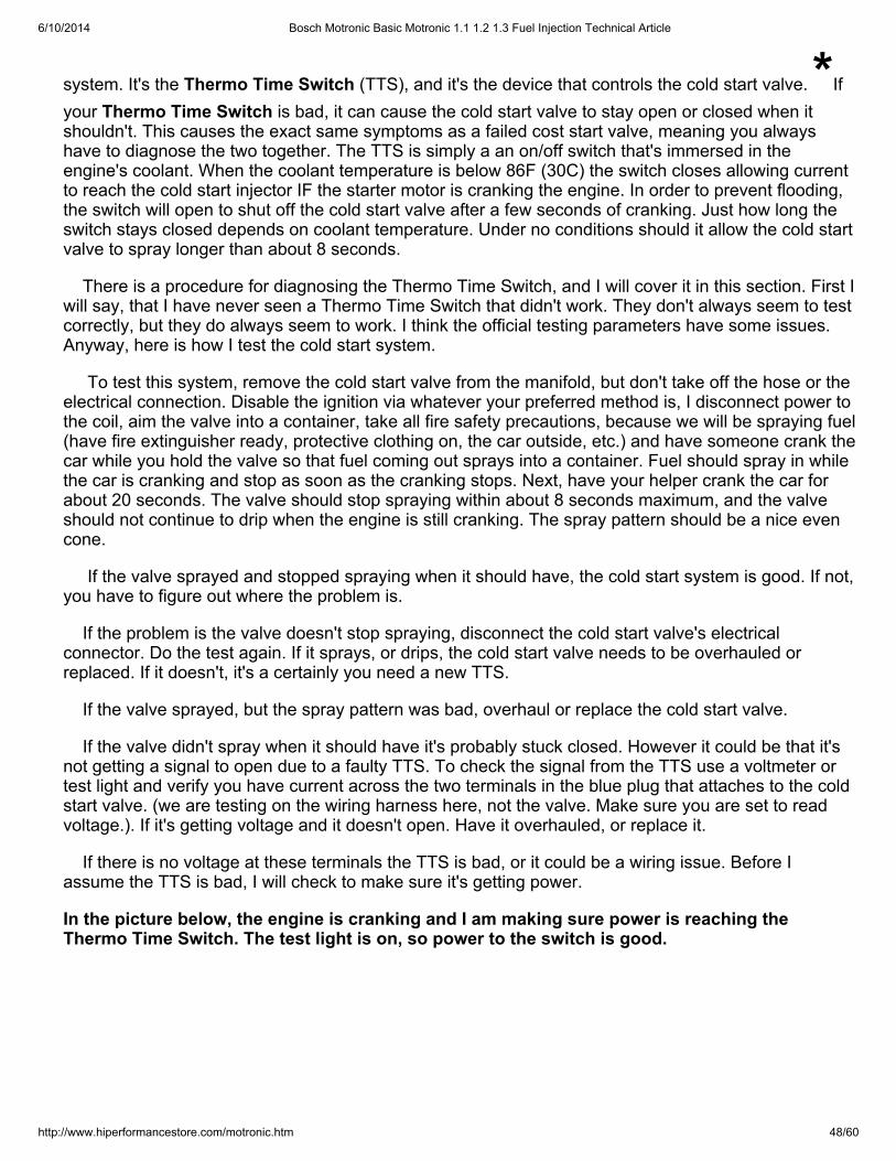
6/10/2014 Bosch Motronic Basic Motronic 1.1 1.2 1.3 Fuel Injection Technical Article
http://www.hiperformancestore.com/motronic.htm 48/60
system. It's the Thermo Time Switch (TTS), and it's the device that controls the cold start valve. *Ifyour Thermo Time Switch is bad, it can cause the cold start valve to stay open or closed when itshouldn't. This causes the exact same symptoms as a failed cost start valve, meaning you alwayshave to diagnose the two together. The TTS is simply a an on/off switch that's immersed in theengine's coolant. When the coolant temperature is below 86F (30C) the switch closes allowing currentto reach the cold start injector IF the starter motor is cranking the engine. In order to prevent flooding,the switch will open to shut off the cold start valve after a few seconds of cranking. Just how long theswitch stays closed depends on coolant temperature. Under no conditions should it allow the cold startvalve to spray longer than about 8 seconds.
There is a procedure for diagnosing the Thermo Time Switch, and I will cover it in this section. First Iwill say, that I have never seen a Thermo Time Switch that didn't work. They don't always seem to testcorrectly, but they do always seem to work. I think the official testing parameters have some issues.Anyway, here is how I test the cold start system.
To test this system, remove the cold start valve from the manifold, but don't take off the hose or theelectrical connection. Disable the ignition via whatever your preferred method is, I disconnect power tothe coil, aim the valve into a container, take all fire safety precautions, because we will be spraying fuel(have fire extinguisher ready, protective clothing on, the car outside, etc.) and have someone crank thecar while you hold the valve so that fuel coming out sprays into a container. Fuel should spray in whilethe car is cranking and stop as soon as the cranking stops. Next, have your helper crank the car forabout 20 seconds. The valve should stop spraying within about 8 seconds maximum, and the valveshould not continue to drip when the engine is still cranking. The spray pattern should be a nice evencone.
If the valve sprayed and stopped spraying when it should have, the cold start system is good. If not,you have to figure out where the problem is.
If the problem is the valve doesn't stop spraying, disconnect the cold start valve's electricalconnector. Do the test again. If it sprays, or drips, the cold start valve needs to be overhauled orreplaced. If it doesn't, it's a certainly you need a new TTS.
If the valve sprayed, but the spray pattern was bad, overhaul or replace the cold start valve.
If the valve didn't spray when it should have it's probably stuck closed. However it could be that it'snot getting a signal to open due to a faulty TTS. To check the signal from the TTS use a voltmeter ortest light and verify you have current across the two terminals in the blue plug that attaches to the coldstart valve. (we are testing on the wiring harness here, not the valve. Make sure you are set to readvoltage.). If it's getting voltage and it doesn't open. Have it overhauled, or replace it.
If there is no voltage at these terminals the TTS is bad, or it could be a wiring issue. Before Iassume the TTS is bad, I will check to make sure it's getting power.
In the picture below, the engine is cranking and I am making sure power is reaching theThermo Time Switch. The test light is on, so power to the switch is good.
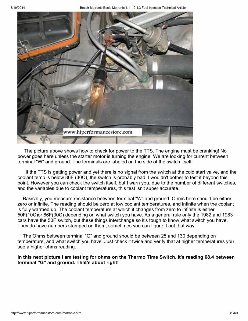
6/10/2014 Bosch Motronic Basic Motronic 1.1 1.2 1.3 Fuel Injection Technical Article
http://www.hiperformancestore.com/motronic.htm 49/60
The picture above shows how to check for power to the TTS. The engine must be cranking! Nopower goes here unless the starter motor is turning the engine. We are looking for current betweenterminal "W" and ground. The terminals are labeled on the side of the switch itself.
If the TTS is getting power and yet there is no signal from the switch at the cold start valve, and thecoolant temp is below 86F (30C), the switch is probably bad. I wouldn't bother to test it beyond thispoint. However you can check the switch itself, but I warn you, due to the number of different switches,and the variables due to coolant temperatures, this test isn't super accurate.
Basically, you measure resistance between terminal "W" and ground. Ohms here should be eitherzero or infinite. The reading should be zero at low coolant temperatures, and infinite when the coolantis fully warmed up. The coolant temperature at which it changes from zero to infinite is either50F(10C)or 86F(30C) depending on what switch you have. As a general rule only the 1982 and 1983cars have the 50F switch, but these things interchange so it's tough to know what switch you have.They do have numbers stamped on them, sometimes you can figure it out that way.
The Ohms between terminal "G" and ground should be between 25 and 130 depending ontemperature, and what switch you have. Just check it twice and verify that at higher temperatures yousee a higher ohms reading.
In this next picture I am testing for ohms on the Thermo Time Switch. It's reading 68.4 betweenterminal "G" and ground. That's about right!
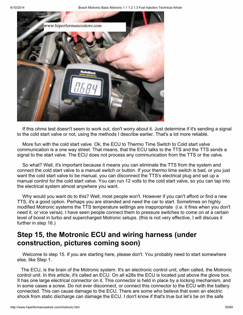
6/10/2014 Bosch Motronic Basic Motronic 1.1 1.2 1.3 Fuel Injection Technical Article
http://www.hiperformancestore.com/motronic.htm 50/60
If this ohms test doesn't seem to work out, don't worry about it. Just determine if it's sending a signalto the cold start valve or not, using the methods I describe earlier. That's a lot more reliable.
More fun with the cold start valve. Ok, the ECU to Thermo Time Switch to Cold start valvecommunication is a one way street. That means, that the ECU talks to the TTS and the TTS sends asignal to the start valve. The ECU does not process any communication from the TTS or the valve.
So what? Well, it's important because it means you can eliminate the TTS from the system andconnect the cold start valve to a manual switch or button. If your thermo time switch is bad, or you justwant the cold start valve to be manual, you can disconnect the TTS's electrical plug and set up amanual control for the cold start valve. You can run 12 volts to the cold start valve, so you can tap intothe electrical system almost anywhere you want.
Why would you want do to this? Well, most people won't. However if you can't afford or find a newTTS, it's a good option. Perhaps you are stranded and need the car to start. Sometimes on highlymodified Motronic systems the TTS temperature settings are inappropriate (i.e. it fires when you don'tneed it, or vice versa). I have seen people connect them to pressure switches to come on at a certainlevel of boost in turbo and supercharged Motronic setups. (this is not very effective, I will discuss itfurther in step 16.)
Step 15, the Motronic ECU and wiring harness (underconstruction, pictures coming soon) Welcome to step 15. If you are starting here, please don't. You probably need to start somewhereelse, like Step 1.
The ECU, is the brain of the Motronic system. It's an electronic control unit, often called, the Motroniccontrol unit. In this article, it's called an ECU. On all e28s the ECU is located just above the glove box.It has one large electrical connector on it. This connector is held in place by a locking mechanism, andin some cases a screw. Do not ever disconnect, or connect this connector to the ECU with the batteryconnected. This can cause damage to the ECU. There are some who believe that even an electricshock from static discharge can damage the ECU. I don't know if that's true but let’s be on the safe
6/10/2014 Bosch Motronic Basic Motronic 1.1 1.2 1.3 Fuel Injection Technical Article
http://www.hiperformancestore.com/motronic.htm 51/60
side and assume it is.
If you were lead to this step from somewhere else in this article, you are in a world of pain. It meansyou either have a bad ECU, or a problem in the wiring harness between the ECU and some underhood component. It's most likely going to be in the wiring.
There are some who say that ECUs don't fail. I can assure you that's incorrect. This logic comesfrom a time when electronic fuel injection was new, and perfectly working ECUs were often blamed forother faults, usually air leaks and weak grounds. Combine this with the fact that when new or newish,these ECUs were pretty much bullet proof and this lead people to over react and say that the ECUsnever fail. Fast forward to present day. Now these ECUs are 20-30 years old. They have had a lot ofheat and vibration over time. Some have been removed, re-installed, modified, and sometimes
abused. It's still VERY VERY rare, but the ECUs can fail. *A bad ECU, or wiring harness can causeany possible running issue. Every symptom an engine can have related to fuel or spark can be causedby a failure in these components.
With that said, I have never seen a failed Bosch Motronic Basic or 1.1 ECU fail. I have seenproblems with the Bosch L-Jetronic ECUs, however they are one generation older. So I can't stressenough, that the odds of you having a bad ECU are very low, but it's possible.
Unfortunately, a thorough, easy and efficient test of the Bosch ECU involves some very rare, andnearly unobtainable Bosch testing equipment. Without it, you will have to find ECU faults via theprocess of elimination. This isn't nearly as bad as it sounds. It involves checking the component, andthe wiring harness. If those two things are OK, and the component in question still doesn't work, theproblem is in the ECU. This method of testing is a lot easier than it sounds.
To understand how we are going to do this just follow along. First, DISCONNECT THE BATTERY. Iused all capitals there for a reason. If you don't, you could damage the ECU. Next, remove the ECU.The connector is usually hinged at one end, and it will have some sort of retaining lock, andsometimes a screw. Remove the connector carefully. The electrical terminals are tiny and delicate.
Once the connector is off, take a look at all of the terminals. If there is any corrosion here it must becleaned up. Now, put the ECU somewhere safe, like in the backseat. If you take it out of the car, youincrease the risk of static electricity (although I think the risk is zero anyway). Now, go and connect thebattery because for many of these tests you will need voltage at the connector.
If you have Motronic basic, you have a 35 pin connector. On this connector the terminals arenumbered in a logical way. There are 18 connectors in one row and 17 in the other row. With the 18connectors on top, they are numbered from left to right 1-18, the second row are 19-35.
If you have Motronic 1.1 the terminals are numbered backwards. There are 55 connectors , the firstrow has 19, the other two have 18. With the longer row on top they are numbered 1-19 STARTINGFROM THE RIGHT. In other words you read the numbers right to left. The second row has 20-37 andthe third 38-55. On a Motronic 1.1 system these are all numbered from right to left.
I like to start by making sure the ECU is getting power. Look at the charts below, make sure you arelooking at the chart for your ECU, and follow the procedures. For example, If you have a 533i or 535iyou will be working with terminals 18, and 35. Turn on your ignition and make sure you seeapproximately battery voltage between terminal 18 and ground, and between terminal 35 and ground.If you don't have power here, there is no way your car will run. Go back to Step 4 and check the mainrelay. The ECU gets its power from the main relay. If that checks out, then there is a connection loosesomewhere, or a problem in the wiring.
Wiring Harness:
6/10/2014 Bosch Motronic Basic Motronic 1.1 1.2 1.3 Fuel Injection Technical Article
http://www.hiperformancestore.com/motronic.htm 52/60
Like a bad ECU, a wiring harness can cause any possible running issue. * Every symptom anengine can have related to fuel or spark can be caused by a failure here.
LONG AND BORING SECTION AHEAD. L
First we need to do a good visual inspection. Look at all the connectors under the hood to makesure they are secure. Next looks for problems with the wiring itself. Most of these problems are usuallyfound within just a few inches of a connector. This is because repeated flexing of the wire sometimescauses the insulation or the wiring itself to break. This is easy enough to test for. If the engine will idle,gently wiggle the suspected wire. If the idle characteristics change you probably have a problem withthe connector or the wiring near it. For some reason, the wiring/connector problems I usually find areat or near the injector connectors. I am not really sure why. They are subjected to the same amount ofheat and vibration as any other connector that mounted to the engine. It’s probably due to abuse atsome point in the car’s life. These connectors can be frustrating to remove, especially if they are notthe later “squeeze to release” type. I think this causes people to tug on them a little too hard.
OK, so all the wiring and connectors look OK but the car still has an issue, and we suspect it’s in thewiring somewhere between the connector and the ECU. This is actually pretty easy to test for.Obviously you can’t do this visually because the wires normally join into a bundle, which joins into abigger bundle working its way towards the ECU. To check every wire visually would be a monumentaltask. There is another way!
Once again, we are going to need our OHM meter. You could also do this with a continuity tester,but I am going to assume you have an OHM meter. Start by disconnecting the ECU, you will needeasy access to the terminals on the ECU’s connector. That means the connector that’s a part of thewiring harness (NEVER TOUCH AN OHM METER TO ANY PART OF THE ECU). We are workingwith the big connector on the ECU’s wiring harness.
All we need to do is to test for resistance between the terminal on the ECU’s Connector and theconnector that’s at the other end of the associated wire. Simple right? To figure out which connectorgoes where we need to have a look at the factory wiring diagram. CAUTION! Just about everypossible version of this car has a different ECU, and thus different wiring configuration. I am going topost the key diagrams for the MANUAL transmission E28 535i, the Automatic transmission version,and the M5 with the S38 engine. They are all different. MAKE SURE YOU ARE LOOKING at thecorrect diagram.
So, how are we going to do this? Well, in this example, let’s say we have a 1988 535i with a manualtransmission. It’s been having a problem that seems related to the throttle position switch; however theswitch itself tests fine so we need to check the associated wiring. We take a look at the correct wringdiagram shown below and see that both terminals 2 and 3 connect the ECU to the switch. Using ourOHM meter and probably some extra wiring so that it will reach, we check for resistance betweenterminal 2 on the wiring harness at the ECU end, and terminal 2 on the wiring harness at the switchend. The resistance should be zero, or at least very close to it. If the resistance is infinite, doublecheck to make sure you are touching the correct terminals.
Every wire you check this way should have zero, or nearly zero resistance. If it doesn’t, the wiring isprobably damaged. The damage is probably near the connector itself, or at a high stress point,normally a place where the wiring harness attaches to a bracket or passes through the firewall.
NOTICE the diagram below is for the E28 535i with a MANUAL transmission.
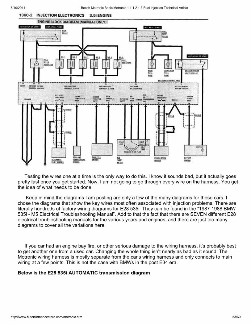
6/10/2014 Bosch Motronic Basic Motronic 1.1 1.2 1.3 Fuel Injection Technical Article
http://www.hiperformancestore.com/motronic.htm 53/60
Testing the wires one at a time is the only way to do this. I know it sounds bad, but it actually goespretty fast once you get started. Now, I am not going to go through every wire on the harness. You getthe idea of what needs to be done.
Keep in mind the diagrams I am posting are only a few of the many diagrams for these cars. Ichose the diagrams that show the key wires most often associated with injection problems. There areliterally hundreds of factory wiring diagrams for E28 535i. They can be found in the “1987-1988 BMW535i - M5 Electrical Troubleshooting Manual”. Add to that the fact that there are SEVEN different E28electrical troubleshooting manuals for the various years and engines, and there are just too manydiagrams to cover all the variations here.
If you car had an engine bay fire, or other serious damage to the wiring harness, it’s probably bestto get another one from a used car. Changing the whole thing isn’t nearly as bad as it sound. TheMotronic wiring harness is mostly separate from the car’s wiring harness and only connects to mainwiring at a few points. This is not the case with BMWs in the post E34 era.
Below is the E28 535i AUTOMATIC transmission diagram
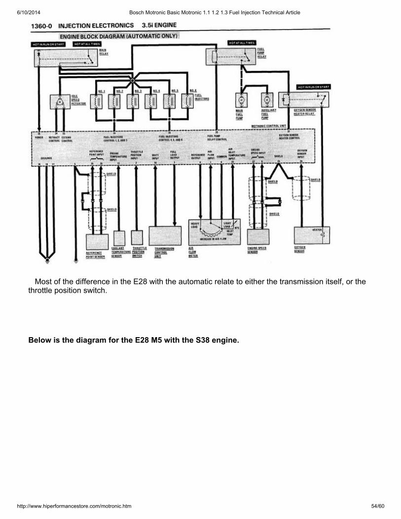
6/10/2014 Bosch Motronic Basic Motronic 1.1 1.2 1.3 Fuel Injection Technical Article
http://www.hiperformancestore.com/motronic.htm 54/60
Most of the difference in the E28 with the automatic relate to either the transmission itself, or thethrottle position switch.
Below is the diagram for the E28 M5 with the S38 engine.
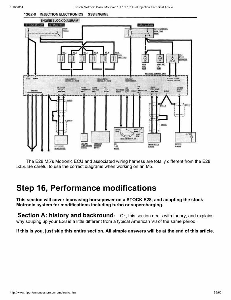
6/10/2014 Bosch Motronic Basic Motronic 1.1 1.2 1.3 Fuel Injection Technical Article
http://www.hiperformancestore.com/motronic.htm 55/60
The E28 M5’s Motronic ECU and associated wiring harness are totally different from the E28535i. Be careful to use the correct diagrams when working on an M5.
Step 16, Performance modificationsThis section will cover increasing horsepower on a STOCK E28, and adapting the stockMotronic system for modifications including turbo or supercharging.
Section A: history and backround: Ok, this section deals with theory, and explainswhy souping up your E28 is a little different from a typical American V8 of the same period.
If this is you, just skip this entire section. All simple answers will be at the end of this article.
6/10/2014 Bosch Motronic Basic Motronic 1.1 1.2 1.3 Fuel Injection Technical Article
http://www.hiperformancestore.com/motronic.htm 56/60
First a little backround on the E28. In its day, even the wimpy 528e was a pretty quick car. The 535iwas one of the fastest cars you could buy. It could accelerate fast to a top speed over 130mph, whenmost new sedans couldn’t top 100mph. The E28 M5 can reach 150mph!
For comparison, the California Highway Patrol’s Dodge St. Regis police car, which were all over theplace throughout the 80’s, had a top speed (with the light bar installed) of about 90mph, and it took twoMILES of flat road to reach it! The St. Regis was fast enough to catch most speeders. That shouldexplain just how fast a 535i was relative to other cars of the period.
In the 80’s this is what the cops in California were chasing people with. As shown here it has atop speed of about 90mph. Even worse, it couldn’t exceed 60mph up the Conejo Grade, or theGrapevine Hill.
Times sure have changed. Today most 3.4 liter sixes have about 100hp more than the E28 535i,and quite a few engines in that size range have twice as much. Why does this matter? It mattersbecause Automotive performance is relative, and relative to everything else from its time, the E28 isalready pretty darn fast.
I am going to focus on the 535i’s engine, but everything I write here will apply to the other BMWs ofthe period.
The BMW 535i’s engine was pretty hot in its day. It has a somewhat aggressive camshaft, but lowcompression (8:1, which was normal for the time). Its exhaust, and intake are decent, and its ECU

6/10/2014 Bosch Motronic Basic Motronic 1.1 1.2 1.3 Fuel Injection Technical Article
http://www.hiperformancestore.com/motronic.htm 57/60
programming is pretty close to optimal. The factory did a good job with their engineering and didn’tleave a lot of easy horsepower on the table.
We can easily modify the fuel injection system to spray in more fuel, but that by its self won’t help. Ifit would, we could simply crimp the fuel pressure regulator’s return line closed and see a big increasein power. Of course that won’t work!
NOW THIS IS IMPORTANT, the engine puts the demand on the fuel injection system. It is notthe other way around. In stock form, the Motronic system provides an air fuel ratio at full throttle ofabout 12.5:1. That ratio is ideal for power (excluding knock-limited power). This is backed up by a tonof data, both old and new. The ratio of 12.5:1 is ideal. Screwing with the fuel injection system on astock engine will take the ratio away from that ideal value and decrease power. So, before you getstarted, it’s worth it to go through the technical portion of this article and make sure your fuel injectionsystem is working correctly in the first place. It’s counterproductive to add $1000 in performanceparts that add 10 horsepower only to be losing 15 to clogged fuel injectors, vacuum loss orsome other anomaly.
The traditional methods of increasing horsepower, such as increasing compression, changing cams,free flowing intakes, free flowing exhaust, special chips, and so on, all work on the E28s. Howeverthey are less effective, and thus cost more in terms of horsepower per dollar, than on a typicalAmerican car from the era.
Let’s back up for a moment, say to the 1970s and early 80s, and talk about automotive enginedesign. At that point, traditionally, when an American manufacturer wanted more power they simplyincreased the engine’s displacement. If the customer buying a new Dodge needed more power thanthe base 225ci engine provided, they could opt for a 318, 360, 400, or 440. This offers themanufacturer a number of advantages. First is cost. On a mass production scale, the 318 and 360 costessentially the same amount to make. They are essentially the same engine, just with differentdisplacements. Second is ease of explaining things to the customer. More engine= More Power, and itcosts more money! Any customer, salesman or advertizing executive can handle this concept. Thethird, and this relates to cost is the lack of engineering required. That’s not to say that we didn’t havegood American engineers at the time, we did, it’s just that the bean counters rarely allowed them toshine. It’s very easy to increase power while retaining a smooth idle, and good driveability byincreasing displacement.
The Germans simply didn’t have that option. The price at the pump of gasoline in Europe madeincreases in power via displacement much less attractive due to the hit in fuel economy. Sure, theycould have shoved in a 5.2 liter V8 with 165 horsepower (as in the police car mentioned above), butfuel economy would have suffered. So they went in another direction.
The 535i has a 3.4 liter 6 cylinder. In order to get the power of V8 into an engine with lessdisplacement they used a decent cylinder head, a relatively hot cam, pretty good free-flowing intake,and exhaust. Furthermore, they used what at the time was the best fuel delivery system available,Bosch Motronic.
For comparison we can look at the Dodge 318 with 165hp. It has incredibly restrictive exhaustmanifolds, a very wimpy cam, and its ability to inhale air is heavily restricted by a tiny two barrel carb.The carb is topped by an air filter that’s not designed to flow well, it’s designed to prevent carburetorice, something that’s just not a factor on an injected engine.
Traditional hot rodding technique became traditional because they worked so well on the oldAmerican V8s. It’s no problem to get the old 318 up to 275, or 300 horsepower with heads,compression, cam, intake (in this case meaning converting to a a 4barrel carb or fuel injection), andheaders. This was true of most American V8 of the era.
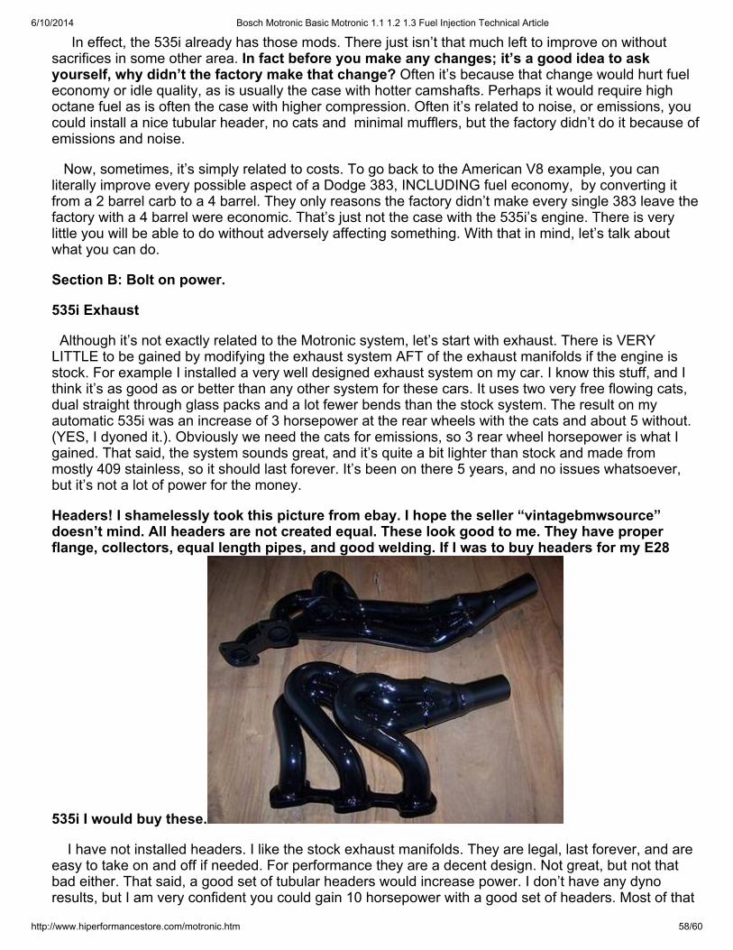
6/10/2014 Bosch Motronic Basic Motronic 1.1 1.2 1.3 Fuel Injection Technical Article
http://www.hiperformancestore.com/motronic.htm 58/60
In effect, the 535i already has those mods. There just isn’t that much left to improve on withoutsacrifices in some other area. In fact before you make any changes; it’s a good idea to askyourself, why didn’t the factory make that change? Often it’s because that change would hurt fueleconomy or idle quality, as is usually the case with hotter camshafts. Perhaps it would require highoctane fuel as is often the case with higher compression. Often it’s related to noise, or emissions, youcould install a nice tubular header, no cats and minimal mufflers, but the factory didn’t do it because ofemissions and noise.
Now, sometimes, it’s simply related to costs. To go back to the American V8 example, you canliterally improve every possible aspect of a Dodge 383, INCLUDING fuel economy, by converting itfrom a 2 barrel carb to a 4 barrel. They only reasons the factory didn’t make every single 383 leave thefactory with a 4 barrel were economic. That’s just not the case with the 535i’s engine. There is verylittle you will be able to do without adversely affecting something. With that in mind, let’s talk aboutwhat you can do.
Section B: Bolt on power.
535i Exhaust
Although it’s not exactly related to the Motronic system, let’s start with exhaust. There is VERYLITTLE to be gained by modifying the exhaust system AFT of the exhaust manifolds if the engine isstock. For example I installed a very well designed exhaust system on my car. I know this stuff, and Ithink it’s as good as or better than any other system for these cars. It uses two very free flowing cats,dual straight through glass packs and a lot fewer bends than the stock system. The result on myautomatic 535i was an increase of 3 horsepower at the rear wheels with the cats and about 5 without.(YES, I dyoned it.). Obviously we need the cats for emissions, so 3 rear wheel horsepower is what Igained. That said, the system sounds great, and it’s quite a bit lighter than stock and made frommostly 409 stainless, so it should last forever. It’s been on there 5 years, and no issues whatsoever,but it’s not a lot of power for the money.
Headers! I shamelessly took this picture from ebay. I hope the seller “vintagebmwsource”doesn’t mind. All headers are not created equal. These look good to me. They have properflange, collectors, equal length pipes, and good welding. If I was to buy headers for my E28
535i I would buy these.
I have not installed headers. I like the stock exhaust manifolds. They are legal, last forever, and areeasy to take on and off if needed. For performance they are a decent design. Not great, but not thatbad either. That said, a good set of tubular headers would increase power. I don’t have any dynoresults, but I am very confident you could gain 10 horsepower with a good set of headers. Most of that
6/10/2014 Bosch Motronic Basic Motronic 1.1 1.2 1.3 Fuel Injection Technical Article
http://www.hiperformancestore.com/motronic.htm 59/60
will be in the high RPM range where you don’t drive that much. At low and mid range the gains on astock engine will be minimal. Combine that with the cost, and it’s easy to see why BMW didn’t give ustubular headers on the 535i. At times like this, I like to look at what the factory did. On the M5 they didinclude tubular headers. That makes sense, the car was much more expensive, so as a percentage ofthe cost of the car, it wasn’t too bad, and the engine was designed for higher rpm and higher power sothe advantages would be greater.
Intake
Ok, hold on! Nothing in the performance world seems to create as much argument as aftermarketintake systems.
There is good news here. Changes to the intake can increase power, and for a reasonable cost, butnot for the commonly held reasons. Almost everyone knows that with the other factors fixed, cold air isdenser than warm air. A lot of self proclaimed experts will tell you “the factory already put in a cold airintake!” Thus any cone filter, or other aftermarket setup is a waste of money. Not true! First of all,nearly every fuel injected car ever made has a factory cold air intake. This certainly isn’t unique toBMWs. Carbureted engines didn’t normally have cold air intakes because the manufacturers wereconcerned with carburetor icing.
Now, there is another big factor with intake systems. It’s normally a bigger factor than intake airtemperature. This big factor is manifold pressure. Let’s talk about manifold pressure for a fewmoments to make sure we are all on the same page.
Normal atmospheric pressure at sea level is 14.7 pounds per square inch. For some reason, inautomobiles we measure pressure in normally aspirated cars (meaning NOT under boost from a turboor supercharger) below atmospheric pressure as vacuum in inches of mercury (i.e. 15 inches ofvacuum at idle or whatever) and pressure above as pounds of boost (i.e. 5 pounds of boost.) Thus aturbo car with 5 pounds of boost has 19.7psi of air pressure in it’s manifold when it’s under boost(5+14.7=19.7). At full throttle in a normally aspirated engine we will see about Zero vacuum. More onthis later.
To keep with the automotive norms, I will discuss this in terms of vacuum in inches of Mercury.MORE vacuum equals less air in the intake manifold. Less vacuum means more. That means thatwhen your car is sitting with the engine off, vacuum will be ZERO. That makes sense right? Theengine isn’t drawing in any air, and the intake isn’t air tight, so atmospheric pressure is able to fullywork its way into the plenum . Now, let’s start the engine and let it idle. If you hook up a vacuum gaugeyou will see that it has about 15 inches of vacuum. Why is that? It’s because the throttle blocksincoming air, and the engine is pumping air into the cylinders faster than the atmosphere can shove itthrough the intake system due to the closed throttle. As we increase the throttle air pressure in theplenum increases, meaning vacuum decreases. We are literally giving the engine more air. If Vacuumreaches zero, that means there is essentially no restriction in the intake system. The atmosphere isable to shove itself in as fast and the engine can suck it out of the intake manifold.
This is pretty easy to measure. Simply connect a vacuum gage to the intake manifold downstreamof the throttle and drive the car. When you do this, you will notice something strange. In an E28 535i,at full throttle as the RPM increases pressure in the manifold will start to drop! Meaning it starts todevelop vacuum even at full throttle. Why is this? It’s because of restrictions in the intake system. Wecan figure out where they are, and how much power they are costing us. I’ll cover this in the nextupdate.

6/10/2014 Bosch Motronic Basic Motronic 1.1 1.2 1.3 Fuel Injection Technical Article
http://www.hiperformancestore.com/motronic.htm 60/60
I will have an update for this page soon. I am really busy withturbocharging, and supercharging work at this time.
[ Home ] [ Up ]
Copyright ©2004 Hi Performance Store, Inc Copyright ©2014 HPSImotorsports.com Copyright©2014 HPSImotorsports-Fiat Copyright ©2010 okinjectors.com Copyright ©1999oldebottles.com Last modified: February 28, 2014


![INJECTION - MX17 - spc960.com · bosch mono-motronic ma 1.7 (single-point) x x x alfa romeo 155 2.0 [ts 2] - 155 2.0 ... bosch motronic m 1.7 (multi-point) x x x start with code card](https://img.pdfslide.us/doc/110x75/5aebc4857f8b9a36698ec479/injection-mx17-mono-motronic-ma-17-single-point-x-x-x-alfa-romeo-155-20.jpg)