Embed Size (px)
Citation preview

BORROWED FROM:Physics Applied to RadiologyRADI R250 -- Fall 2003 CH 9
CIRCUITRY
2
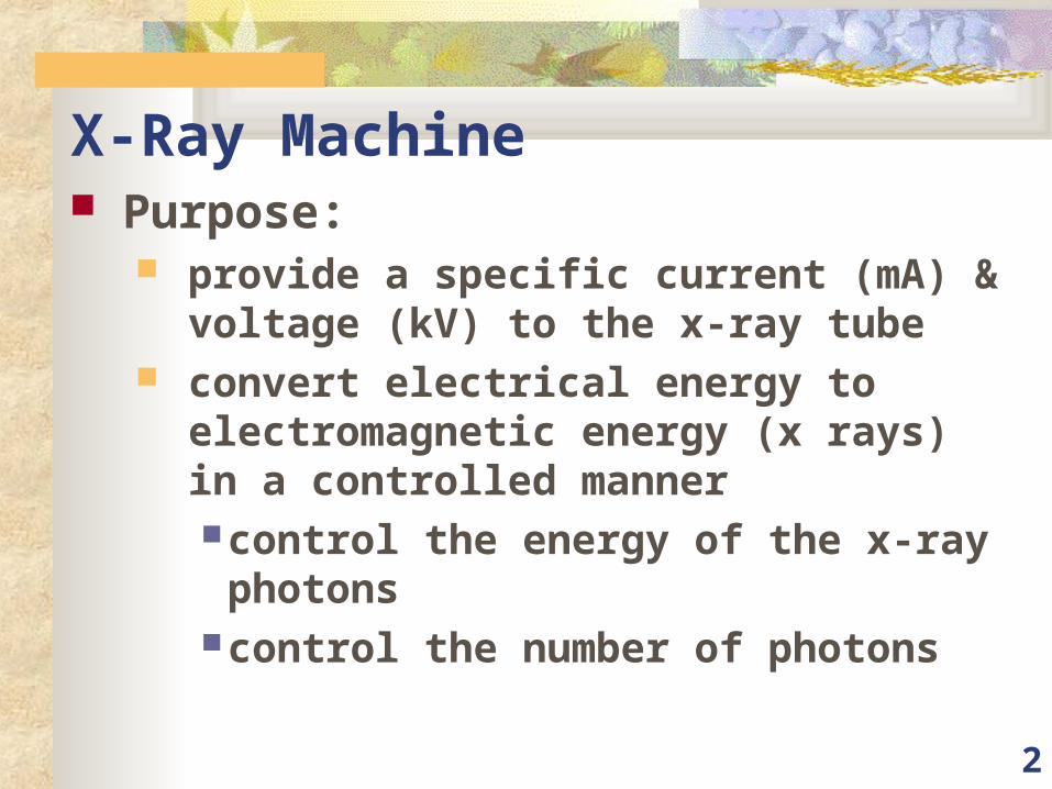
X-Ray Machine Purpose:
provide a specific current (mA) & voltage (kV) to the x-ray tube
convert electrical energy to electromagnetic energy (x rays) in a controlled mannercontrol the energy of the x-ray photonscontrol the number of photons
3
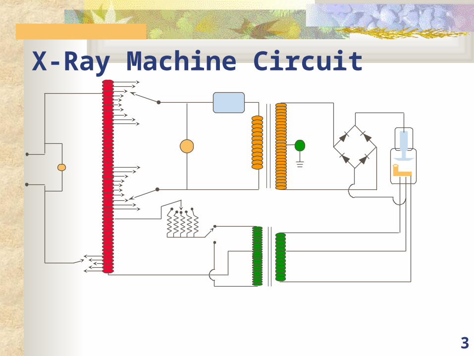
X-Ray Machine Circuit
4
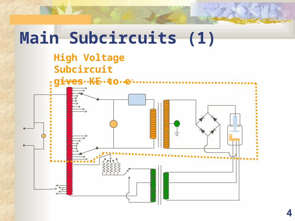
Main Subcircuits (1)High Voltage Subcircuitgives KE to e-
5
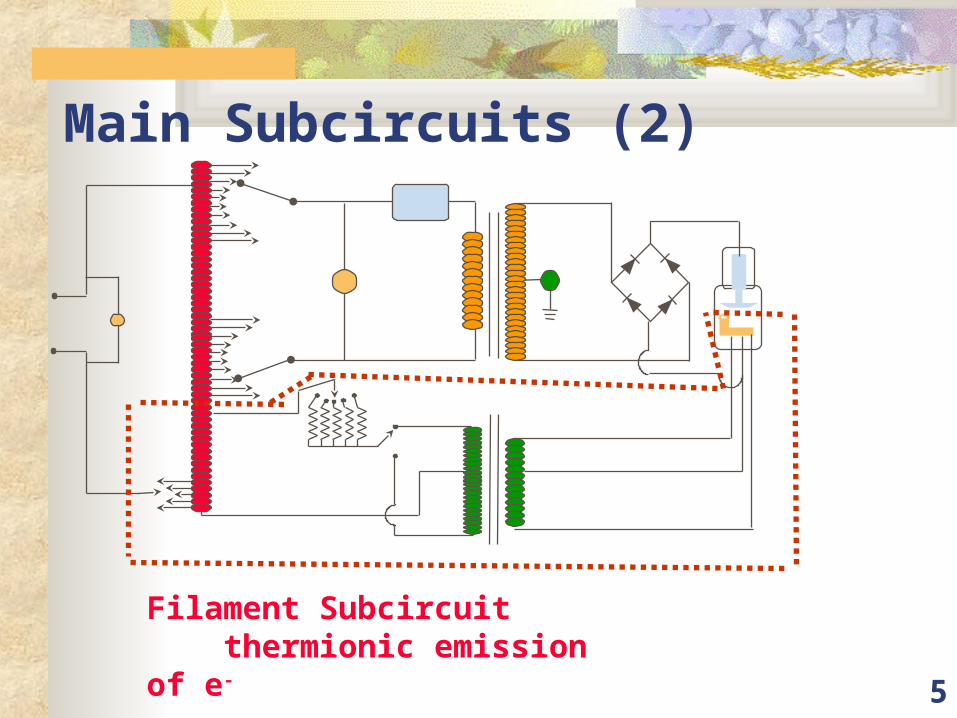
Main Subcircuits (2)
Filament Subcircuit thermionic emission of e-
6
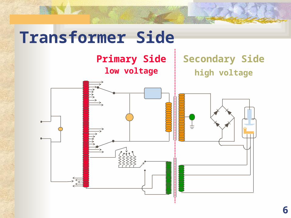
Transformer SidePrimary Side Secondary Side
low voltage high voltage
7
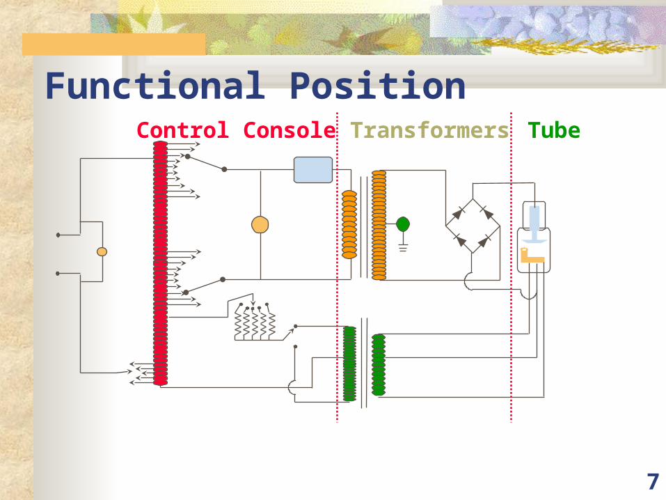
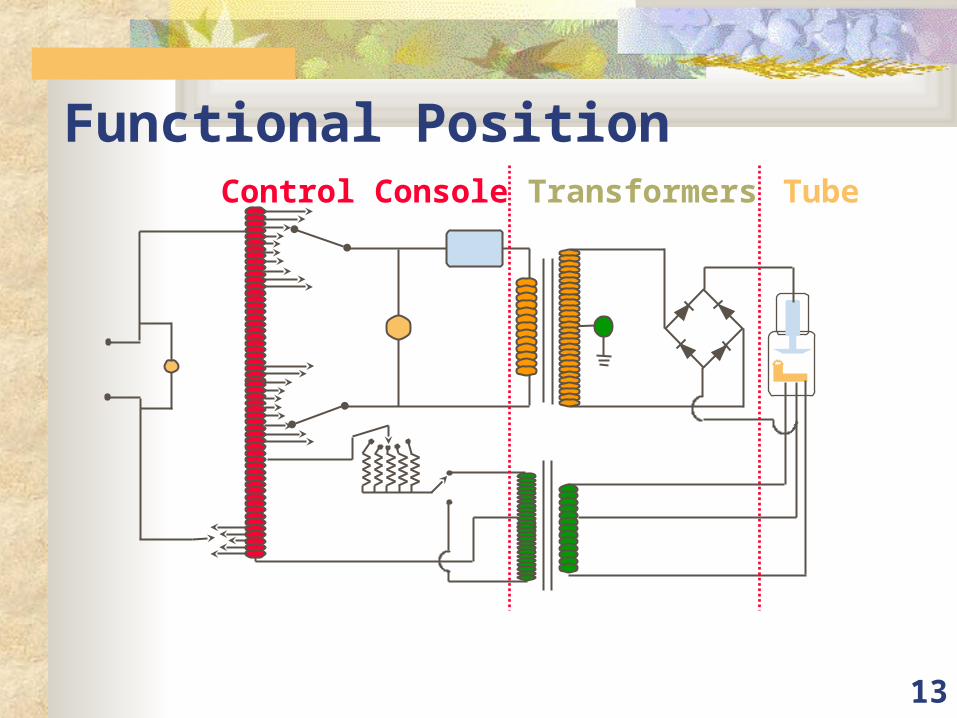
Functional PositionControl Console Transformers Tube
8
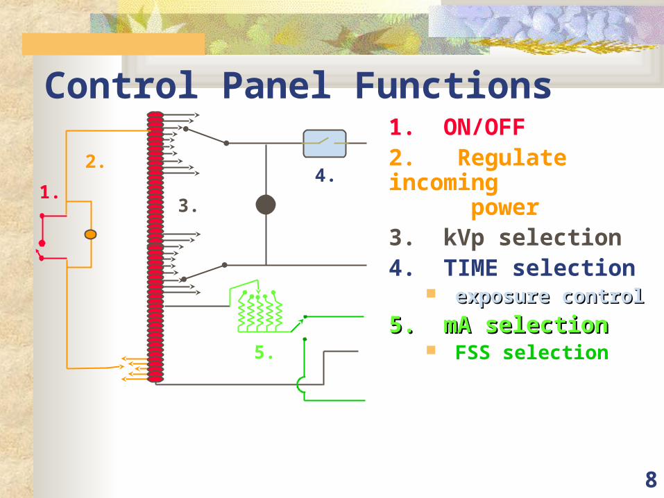
Control Panel Functions1. ON/OFF2. Regulate incoming power3. kVp selection4. TIME selection
exposure controlexposure control
5. mA selection5. mA selection FSS selection
1.
2.
3.
4.
5.
9
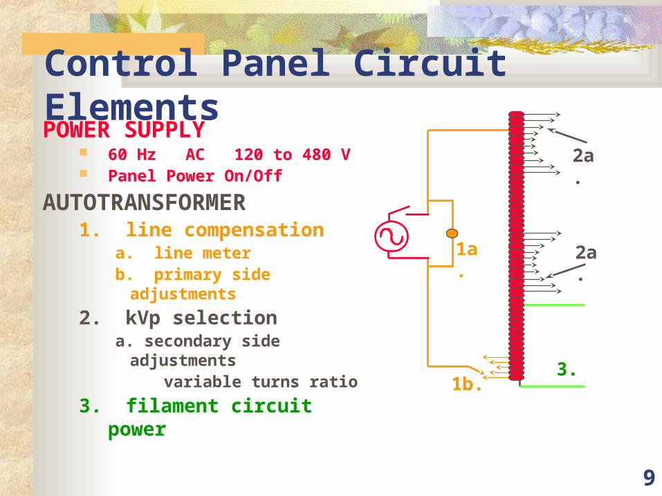
Control Panel Circuit ElementsPOWER SUPPLY
60 Hz AC 120 to 480 V Panel Power On/Off
AUTOTRANSFORMER1. line compensation
a. line meterb. primary side adjustments
2. kVp selectiona. secondary side adjustments variable turns ratio
3. filament circuit power
1a.
1b.
2a.
2a.
3.
10
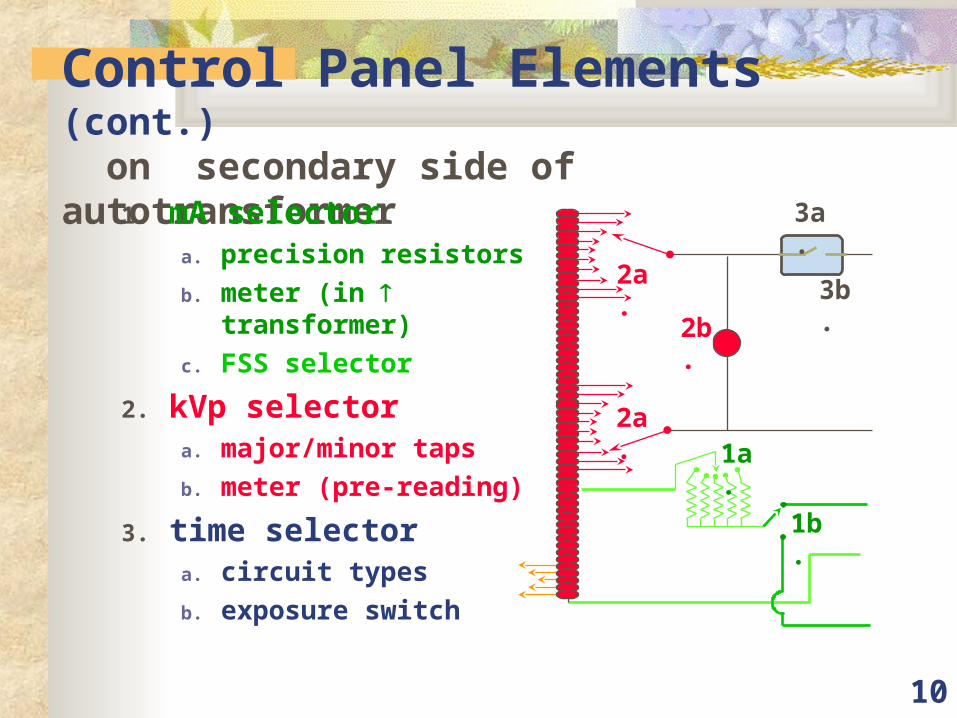
Control Panel Elements (cont.) on secondary side of autotransformer
1. mA selectora. precision resistors
b. meter (in transformer)
c. FSS selector
2. kVp selectora. major/minor taps
b. meter (pre-reading)
3. time selectora. circuit types
b. exposure switch
2a.
2a.
2b.
1a.
1b.
3a.
3b.
11
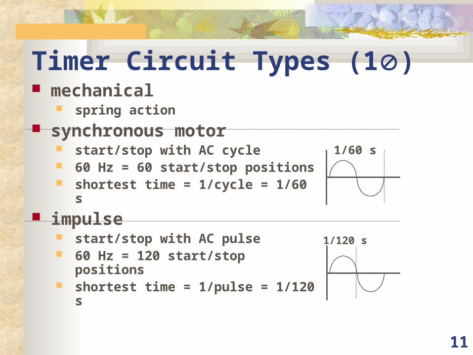
Timer Circuit Types (1) mechanical
spring action
synchronous motor start/stop with AC cycle 60 Hz = 60 start/stop positions shortest time = 1/cycle = 1/60 s
impulse start/stop with AC pulse 60 Hz = 120 start/stop positions shortest time = 1/pulse = 1/120 s
1/60 s
1/120 s
12
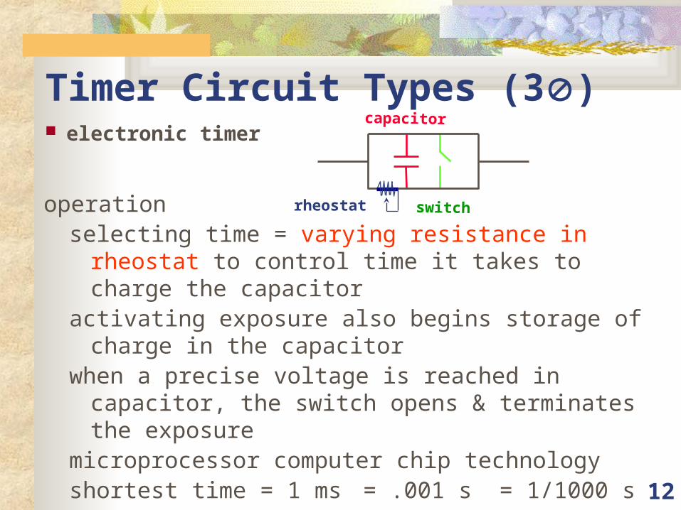
Timer Circuit Types (3) electronic timer
operationselecting time = varying resistance in rheostat to control time
it takes to charge the capacitoractivating exposure also begins storage of charge in the
capacitorwhen a precise voltage is reached in capacitor, the switch
opens & terminates the exposuremicroprocessor computer chip technologyshortest time = 1 ms = .001 s = 1/1000 s
capacitor
rheostat switch
13
Functional PositionControl Console Transformers Tube
14
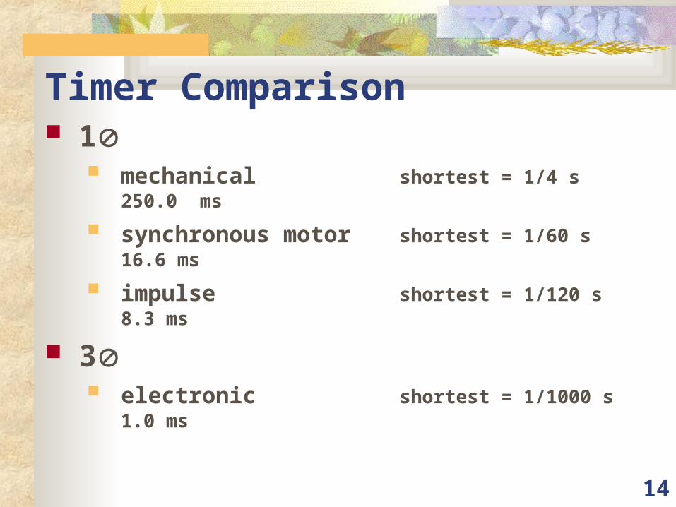
Timer Comparison 1
mechanical shortest = 1/4 s 250.0 ms
synchronous motor shortest = 1/60 s 16.6 ms
impulse shortest = 1/120 s 8.3 ms
3 electronic shortest = 1/1000 s 1.0
ms
15
Timer Circuit Types (3)(cont.)
mAs timer type of electronic timer uses tube current (mA) to charge capacitor time to charge capacitor = time of exposure on secondary side of HV transformer
16
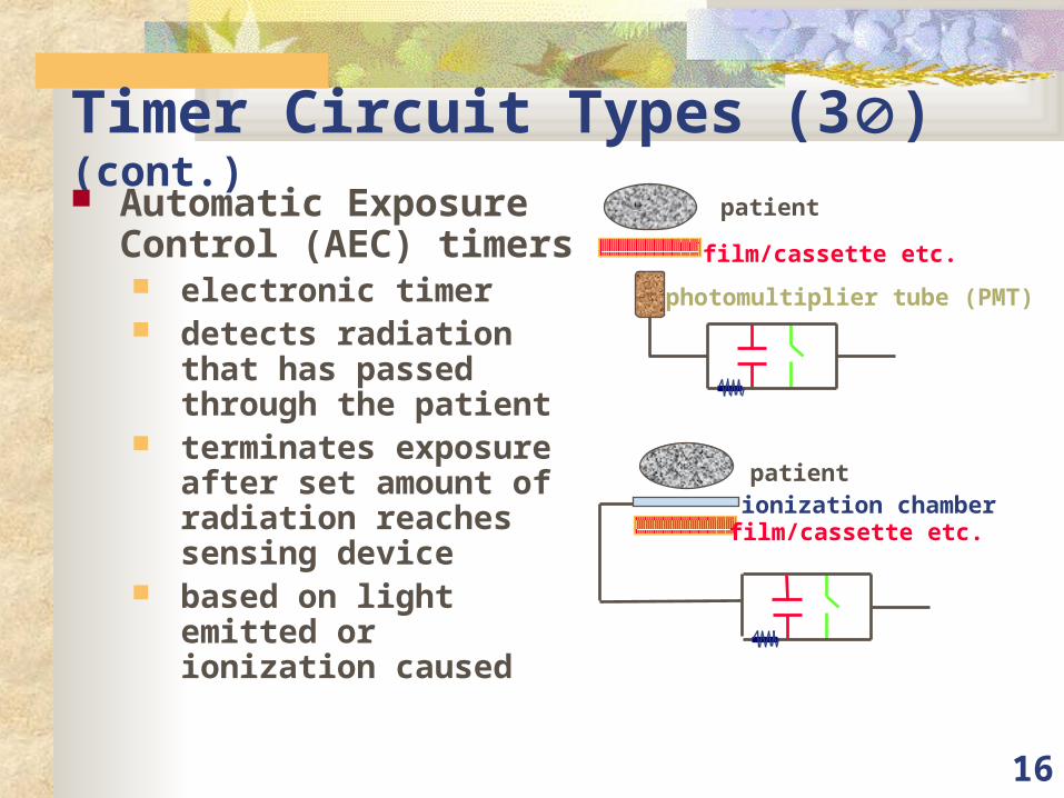
Timer Circuit Types (3)(cont.) Automatic Exposure
Control (AEC) timers electronic timer detects radiation that has
passed through the patient
terminates exposure after set amount of radiation reaches sensing device
based on light emitted or ionization caused
photomultiplier tube (PMT)
film/cassette etc.
patient
film/cassette etc.
patientionization chamber

17
Functional PositionControl Console Transformers Tube
18
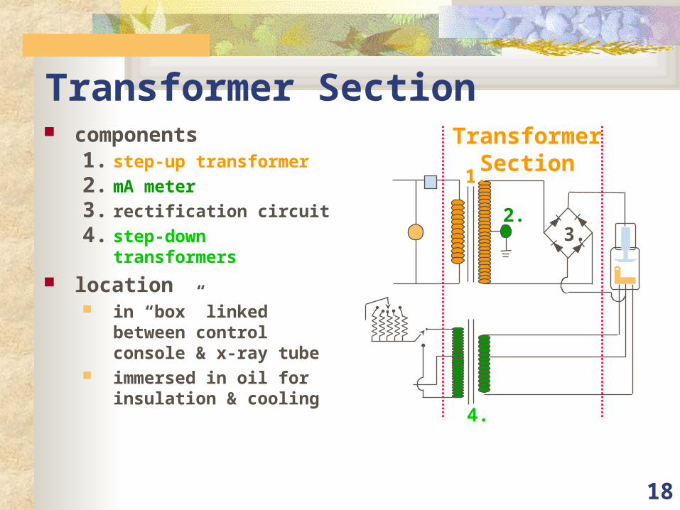
Transformer Section components
1. step-up transformer
2. mA meter
3. rectification circuit
4. step-down transformers
location in “box” linked between
control console & x-ray tube
immersed in oil for insulation & cooling
TransformerSection
1.
2.3.
4.
19
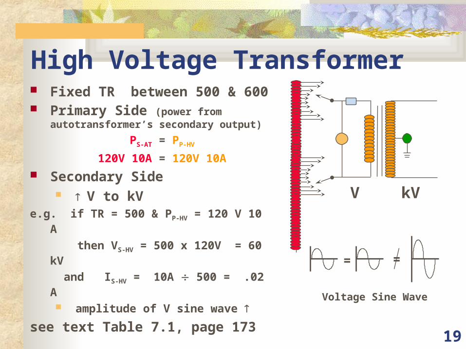
High Voltage Transformer Fixed TR between 500 & 600 Primary Side (power from
autotransformer’s secondary output)
PS-AT = PP-HV
120V 10A = 120V 10A
Secondary Side V to kV
e.g. if TR = 500 & PP-HV = 120 V 10 A
then VS-HV = 500 x 120V = 60 kV
and IS-HV = 10A 500 = .02 A
amplitude of V sine wave
see text Table 7.1, page 173
= =
Voltage Sine Wave
kVV
20
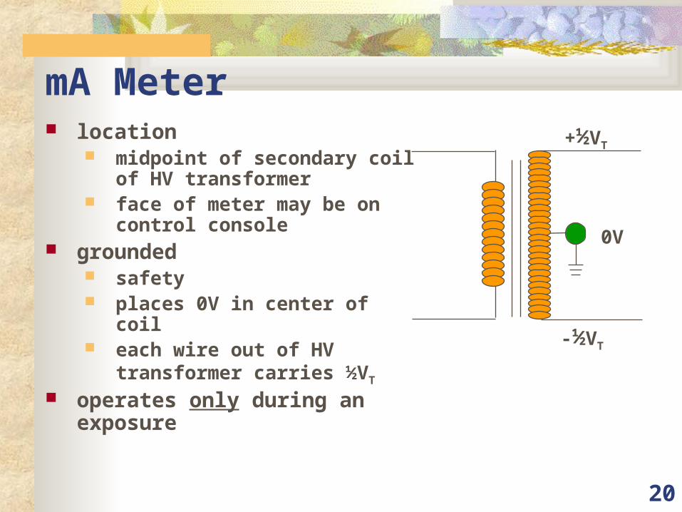
mA Meter location
midpoint of secondary coil of HV transformer
face of meter may be on control console
grounded safety places 0V in center of coil each wire out of HV transformer
carries ½VT
operates only during an exposure
0V
+½VT
-½VT
21
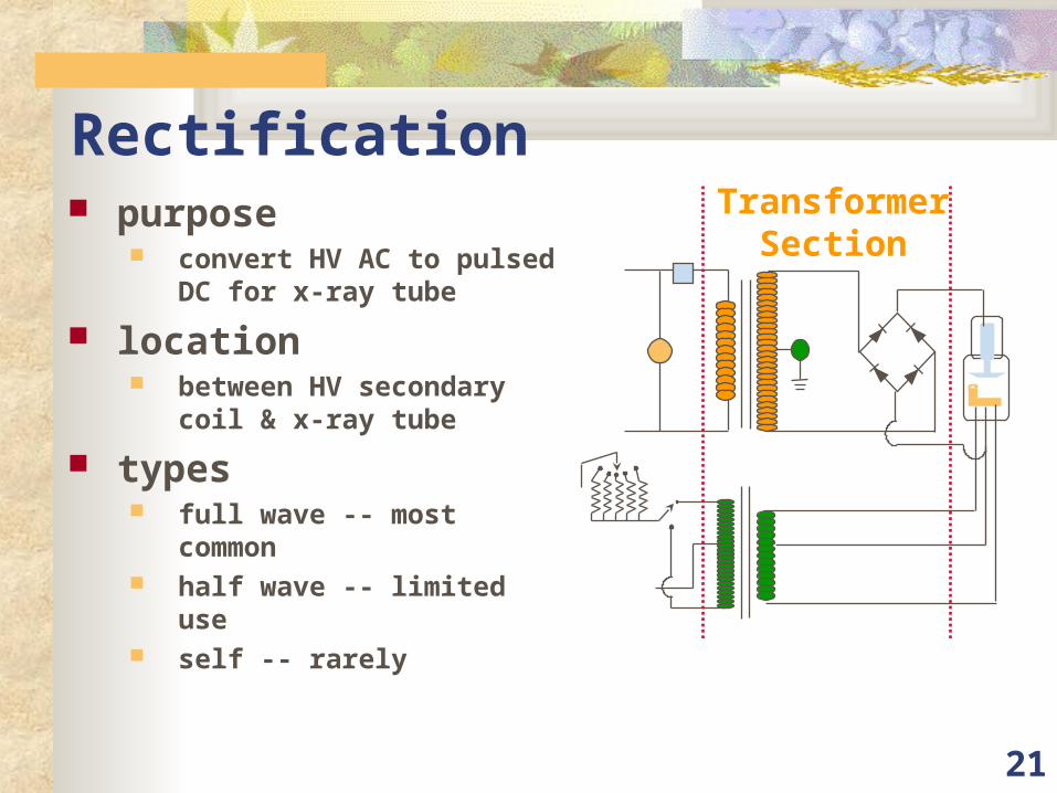
Rectification purpose
convert HV AC to pulsed DC for x-ray tube
location between HV secondary coil
& x-ray tube
types full wave -- most common half wave -- limited use self -- rarely
TransformerSection
22
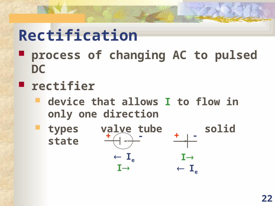
Rectification process of changing AC to pulsed DC rectifier
device that allows I to flow in only one direction
types valve tube solid state
Ie
I
+ -
Ie
I
+ -
23
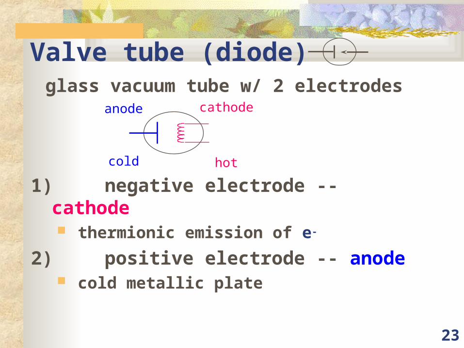
Valve tube (diode) glass vacuum tube w/ 2 electrodes
1) negative electrode -- cathode thermionic emission of e-
2) positive electrode -- anode cold metallic plate
cold hot
anode cathode
24
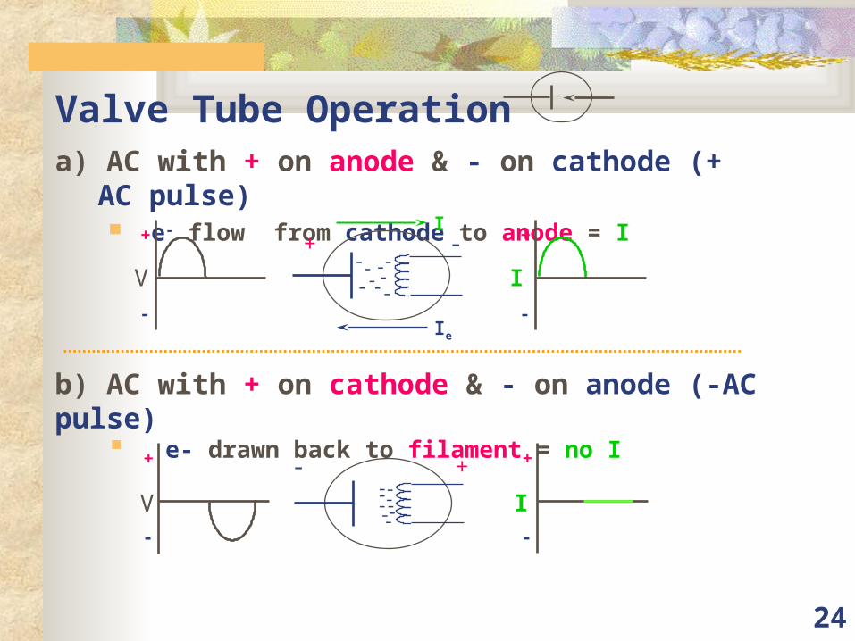
Valve Tube Operationa) AC with + on anode & - on cathode (+ AC pulse)
e- flow from cathode to anode = I
+ -
--
-----
-
-
Ie
I+
-
V
+
-
I
+---
----- --
+
-
V
+
-
I
b) AC with + on cathode & - on anode (-AC pulse) e- drawn back to filament = no I
25
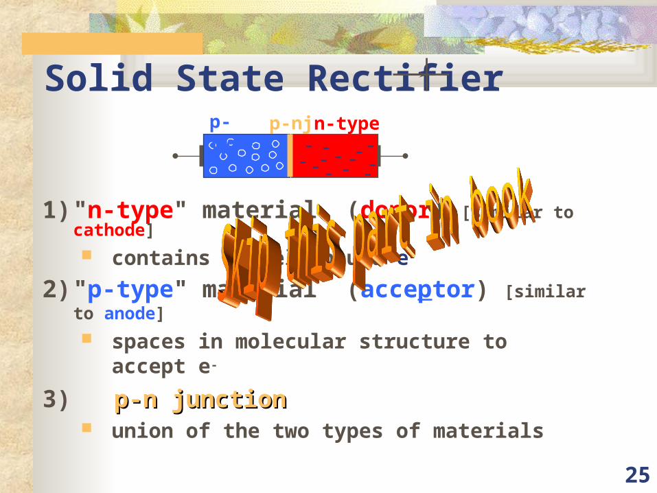
Solid State Rectifier
1) "n-type" material (donor) [similar to cathode]
contains loosely bound e-
2) "p-type" material (acceptor) [similar to anode]
spaces in molecular structure to accept e-
3) p-n junctionp-n junction union of the two types of materials
n-type- - - --
--- - --
--
p-type
p-nj
26
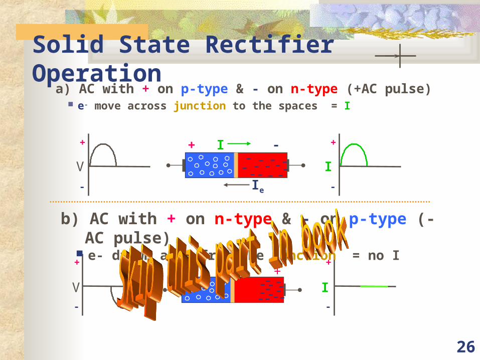
Solid State Rectifier Operationa) AC with + on p-type & - on n-type (+AC pulse)
e- move across junction to the spaces = I
+
-
V
+
-
I
b) AC with + on n-type & - on p-type (-AC pulse) e- drawn away from the junction = no I
+
-
V
+
-
I
+ -I
Ie
- - --- --- - --
- -
+---
- ---
--- -- --
27
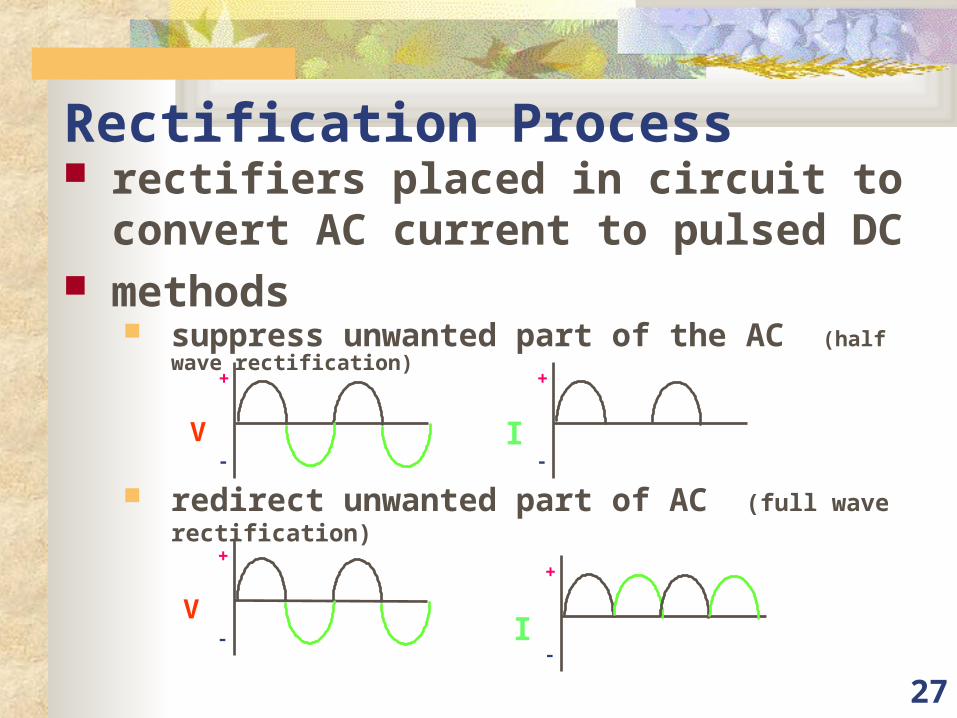
Rectification Process rectifiers placed in circuit to convert AC
current to pulsed DC methods
suppress unwanted part of the AC (half wave rectification)
redirect unwanted part of AC (full wave rectification)
+
-
+
-
+
-
+
-
V
V
I
I
28
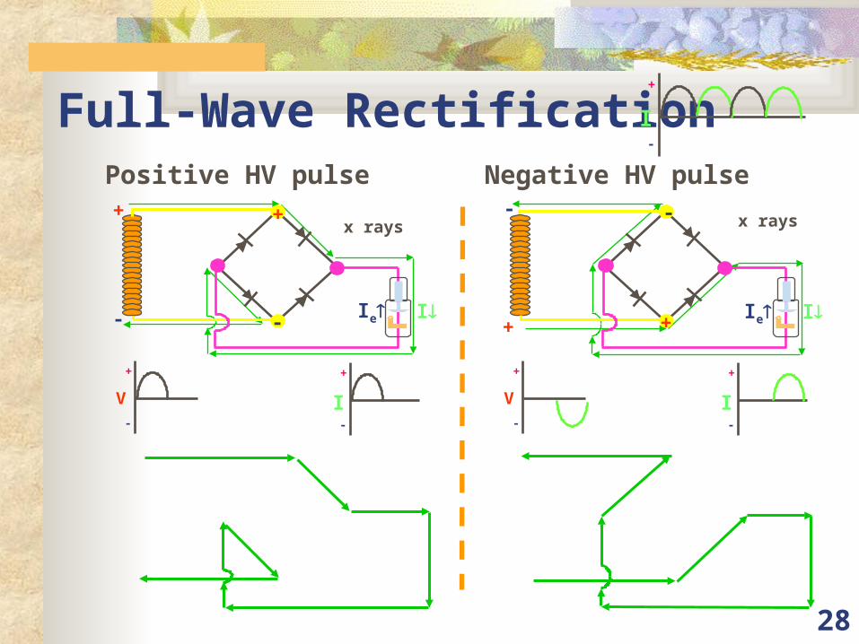
Full-Wave RectificationPositive HV pulse Negative HV pulse
+
-
I
+
- I
+
-
+
-
V
+
-
I
Ie
x rays
+
-
I+
-
+
-
V
+
-
I
Ie
x rays
29
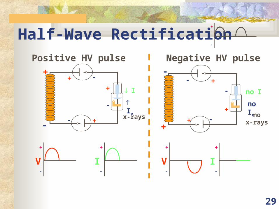
Half-Wave Rectification
Positive HV pulse Negative HV pulse
+
-
+
-
V
+
-
I
+
-
V
+
-
I
x-rays
I
e
I
+
-
+
-
+-
+ -
no Ie
noI
+
-
+
+
-
-no
x-rays
+-
30
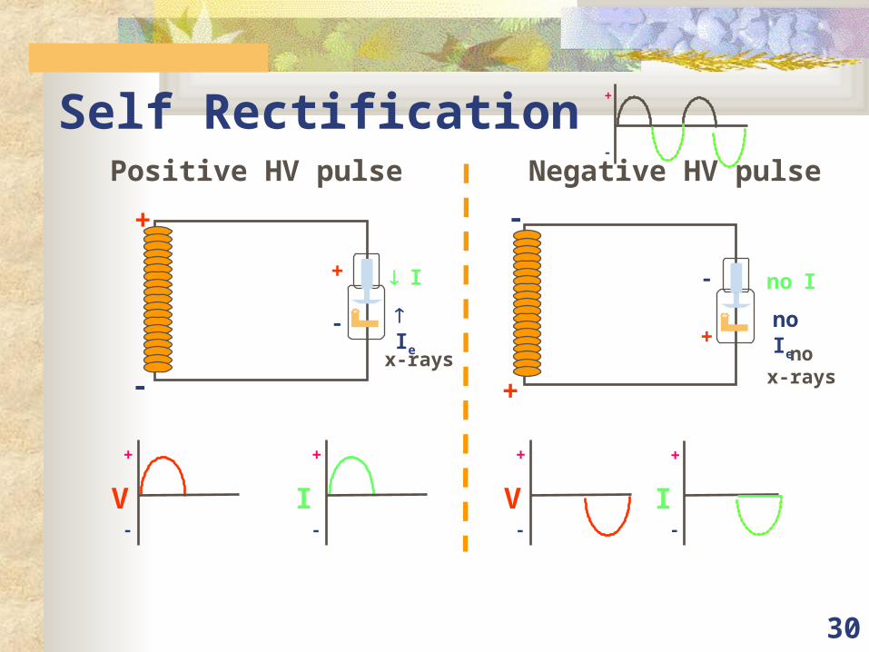
Self RectificationPositive HV pulse Negative HV pulse
+
-
V
+
-
I
+
-
V
no Ie
noI
+
-
+
-
nox-rays
x-rays
I
e
I
+
-
+
-
+
-
I
+
-
31
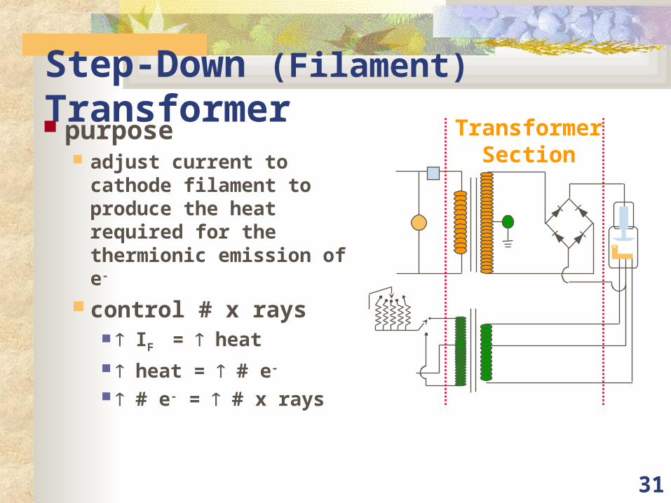
Step-Down (Filament) Transformer purpose
adjust current to cathode filament to produce the heat required for the thermionic emission of e-
control # x rays IF = heat heat = # e-
# e- = # x rays
TransformerSection
32
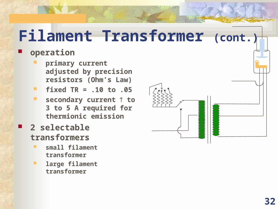
Filament Transformer (cont.) operation
primary current adjusted by precision resistors (Ohm’s Law)
fixed TR = .10 to .05 secondary current to 3
to 5 A required for thermionic emission
2 selectable transformers small filament transformer large filament transformer
33
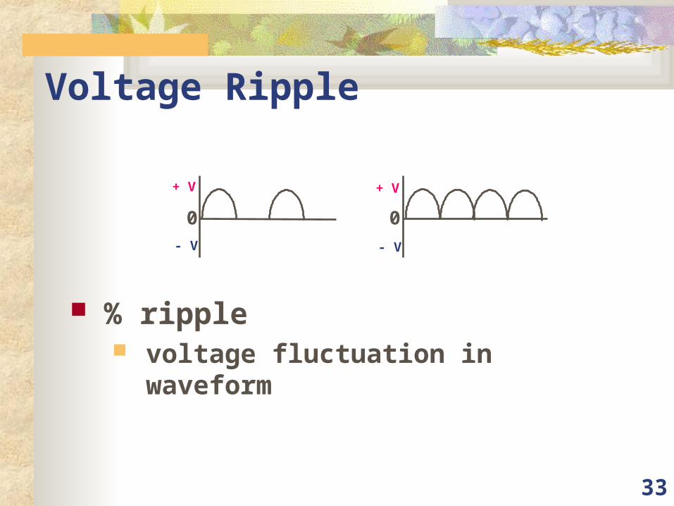
Voltage Ripple
% ripple voltage fluctuation in waveform
+ V
- V
+ V
- V
0 0
34
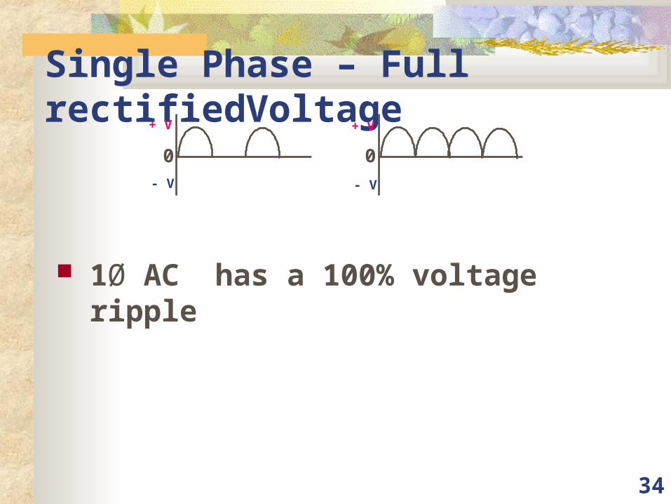
Single Phase – Full rectifiedVoltage
1Ø AC has a 100% voltage ripple
+ V
- V
+ V
- V
0 0
35
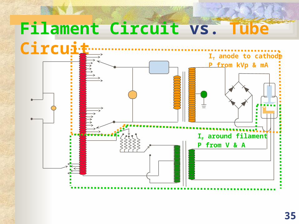
Filament Circuit vs. Tube CircuitIT anode to cathodeP from kVp & mA
IF around filamentP from V & A
36
Circuit Summary 2 major subcircuits
filament circuit thermionic emission of e- at filament
high voltage circuit PD to accelerate e- from cathode to anode
Other circuit parts timing method rectifiers meters
37
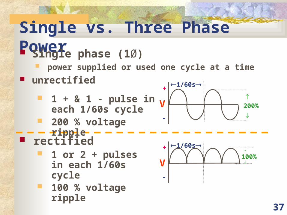
Single vs. Three Phase Power Single phase (1Ø)
power supplied or used one cycle at a time
unrectified
200%
+
-
V
1/60s
V
+
-
100%
1/60s rectified
1 or 2 + pulses in each 1/60s cycle
100 % voltage ripple
1 + & 1 - pulse in each 1/60s cycle
200 % voltage ripple
38
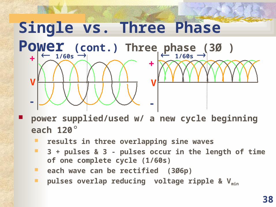
Single vs. Three Phase Power (cont.) Three phase (3Ø )
power supplied/used w/ a new cycle beginning each 120° results in three overlapping sine waves 3 + pulses & 3 - pulses occur in the length of time of one complete
cycle (1/60s) each wave can be rectified (3Ø6p) pulses overlap reducing voltage ripple & Vmin
1/60s +
-
V
1/60s +
-
V
39
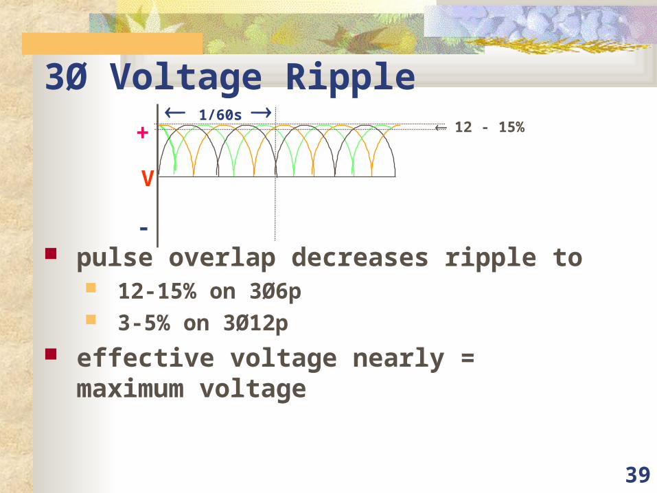
3Ø Voltage Ripple
pulse overlap decreases ripple to 12-15% on 3Ø6p 3-5% on 3Ø12p
effective voltage nearly = maximum voltage
1/60s +
-
V
12 - 15%
40
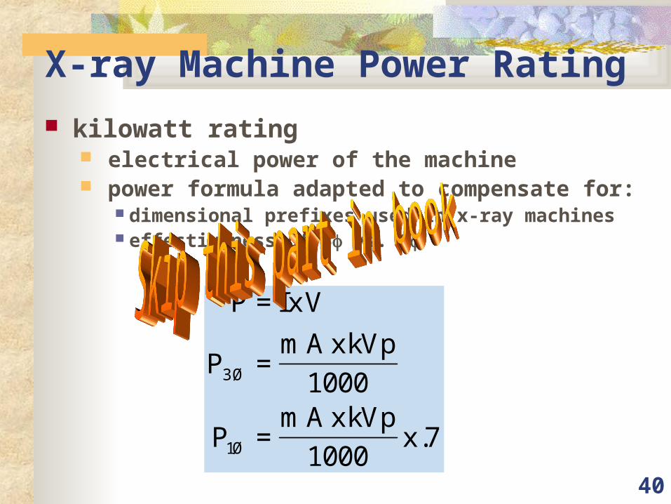
X-ray Machine Power Rating kilowatt rating
electrical power of the machine power formula adapted to compensate for:
dimensional prefixes used in x-ray machines effectiveness of 3 vs. 1
P IxV
PmAxkVp
PmAxkVp
x
=
=
=
3
1
1000
10007
Ø
Ø .
41
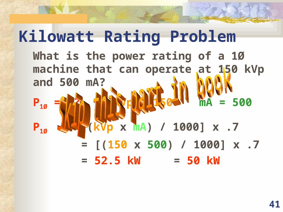
Kilowatt Rating ProblemWhat is the power rating of a 1Ø machine that can operate at 150 kVp and 500 mA?
P1Ø = ?? kVp = 150 mA = 500
P1Ø = [(kVp x mA) / 1000] x .7
= [(150 x 500) / 1000] x .7
= 52.5 kW = 50 kW
42
3Ø comparison to 1Ø 3Ø more efficient than 1Ø 3Ø requires more complex circuitry 3Ø more expensive to install
43
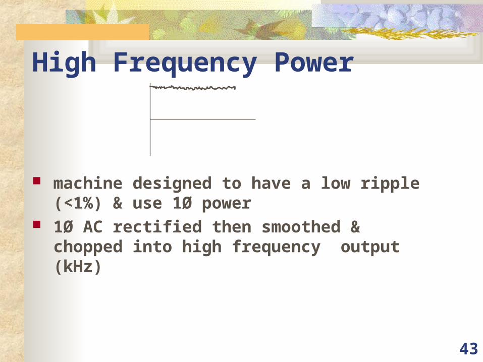
High Frequency Power
machine designed to have a low ripple (<1%) & use 1Ø power
1Ø AC rectified then smoothed & chopped into high frequency output (kHz)
44
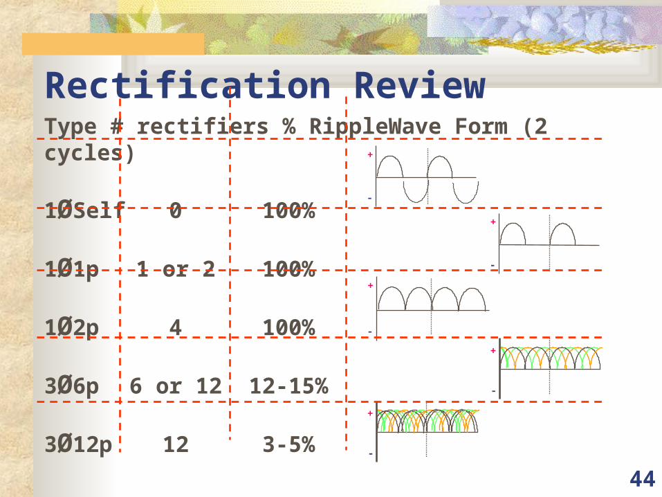
Rectification ReviewType # rectifiers % Ripple Wave Form (2 cycles)
1ØSelf 0 100%
1Ø1p 1 or 2 100%
1Ø2p 4 100%
3Ø6p 6 or 12 12-15%
3Ø12p 12 3-5%
+
-
+
-
+
-
+
-
+
-

45
Single vs. Three Phase Power (cont.) Three phase (3Ø )
power supplied/used w/ a new cycle beginning each 120° results in three overlapping sine waves 3 + pulses & 3 - pulses occur in the length of time of one complete
cycle (1/60s) each wave can be rectified (3Ø6p) pulses overlap reducing voltage ripple & Vmin
1/60s +
-
V
1/60s +
-
V
46
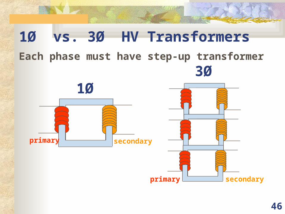
1Ø vs. 3Ø HV Transformers
Each phase must have step-up transformer
1Ø
primary secondary
3Ø
primary secondary
47
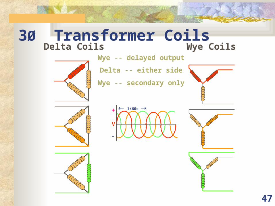
3Ø Transformer Coils
1/60s +
-
V
Wye -- delayed output
Delta -- either side
Wye -- secondary only
Delta Coils Wye Coils
48
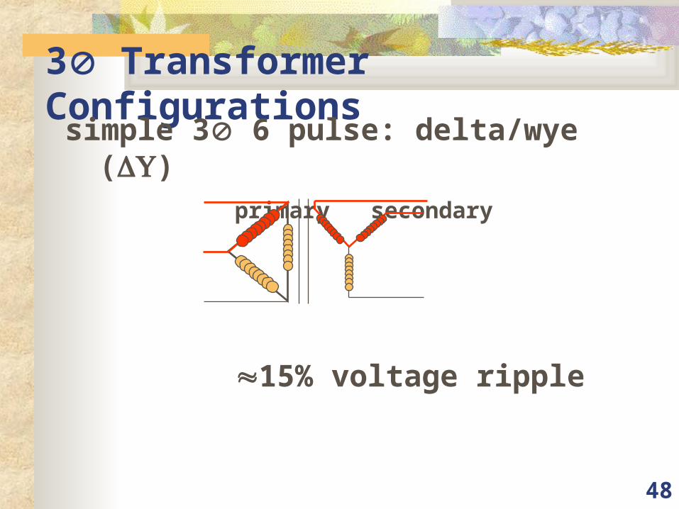
3 Transformer Configurationssimple 3 6 pulse: delta/wye ()
primary secondary
15% voltage ripple

49
3 Trans. Configurations (cont.)
complex 3 6 pulse: delta/wye/wye ()
primary secondary
12% voltage ripple
50
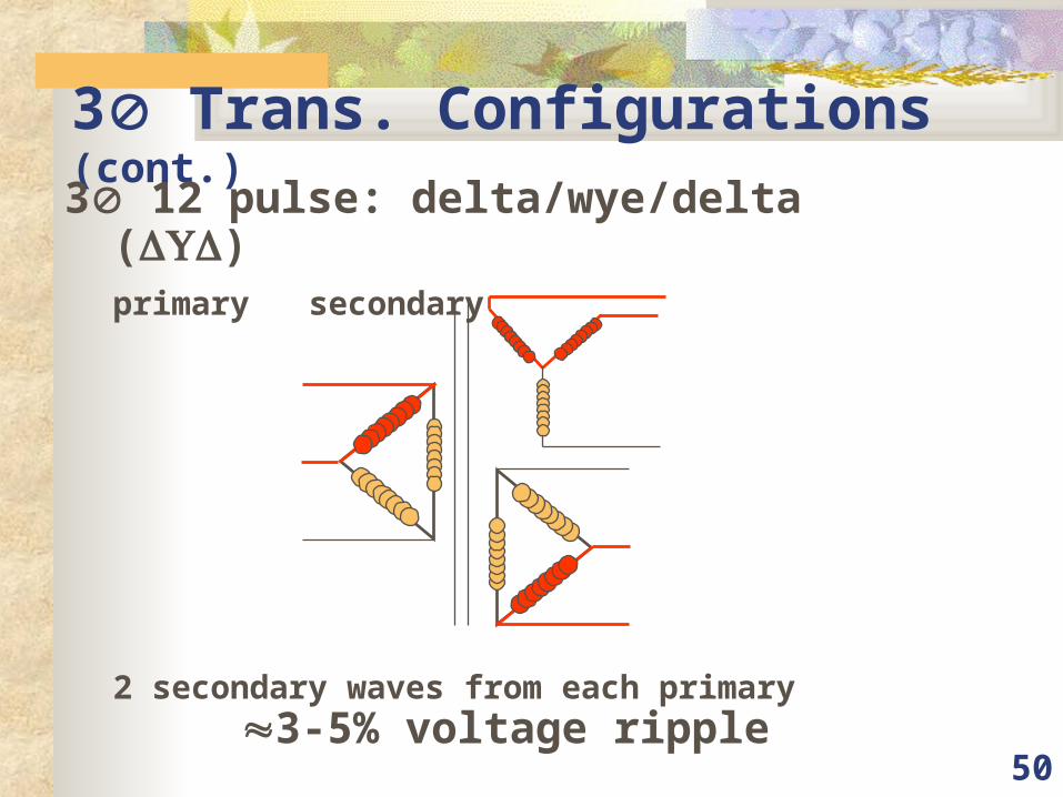
3 Trans. Configurations (cont.)
3 12 pulse: delta/wye/delta ()primary secondary
2 secondary waves from each primary3-5% voltage ripple
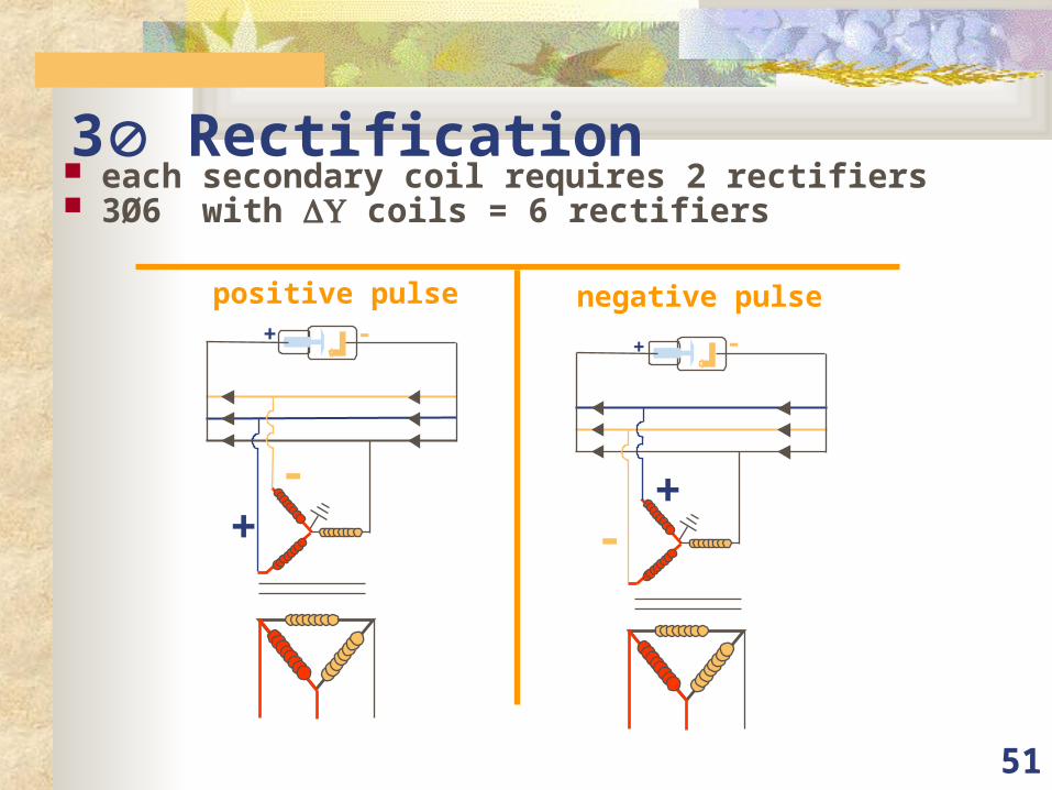
51
3 Rectification each secondary coil requires 2 rectifiers 3Ø6 with coils = 6 rectifiers
positive pulse negative pulse
-+
-+
+-
-+
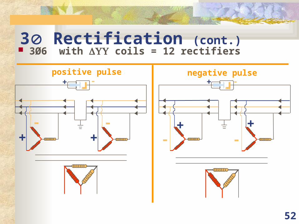
52
3 Rectification (cont.) 3Ø6 with coils = 12 rectifiers
positive pulse negative pulse
-+
-+
-+
-+
-+
-+
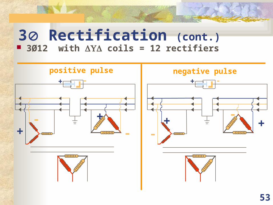
53
3 Rectification (cont.) 3Ø12 with coils = 12 rectifiers
positive pulse negative pulse
-+ -
+
+ -
-+
-+
+ -
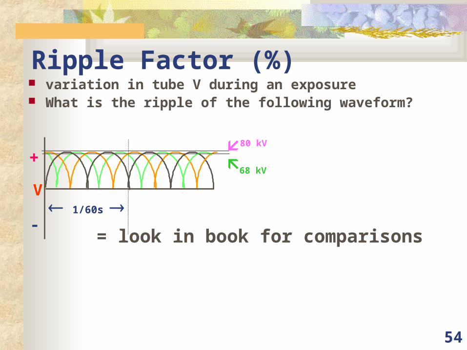
54
Ripple Factor (%) variation in tube V during an exposure What is the ripple of the following waveform?
1/60s
+
-
V
80 kV
68 kV
= look in book for comparisons
55
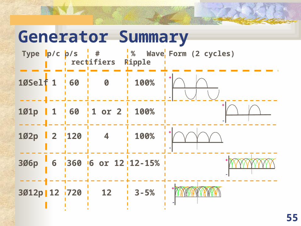
Generator SummaryType p/c p/s # % Wave Form (2 cycles)
rectifiers Ripple
+
-
+
-
+
-
+
-
+
-
1ØSelf 1 60 0 100%
1Ø1p 1 60 1 or 2 100%
1Ø2p 2 120 4 100%
3Ø6p 6 360 6 or 12 12-15%
3Ø12p 12 720 12 3-5%
56
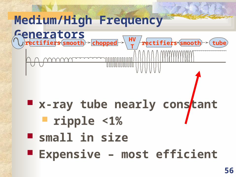
Medium/High Frequency Generators
x-ray tube nearly constant ripple <1%
small in size Expensive – most efficient
rectifiers smooth choppedHVT
rectifiers smooth tube
57
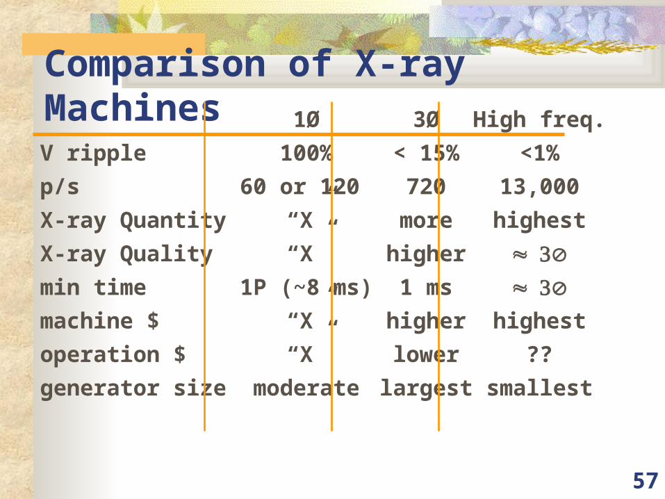
Comparison of X-ray Machines1Ø 3Ø High freq.
V ripple 100% < 15% <1%
p/s 60 or 120 720 13,000
X-ray Quantity “X” more highest
X-ray Quality “X” higher min time 1P (~8 ms) 1 ms machine $ “X” higher highest
operation $ “X” lower ??
generator size moderate largest smallest
58
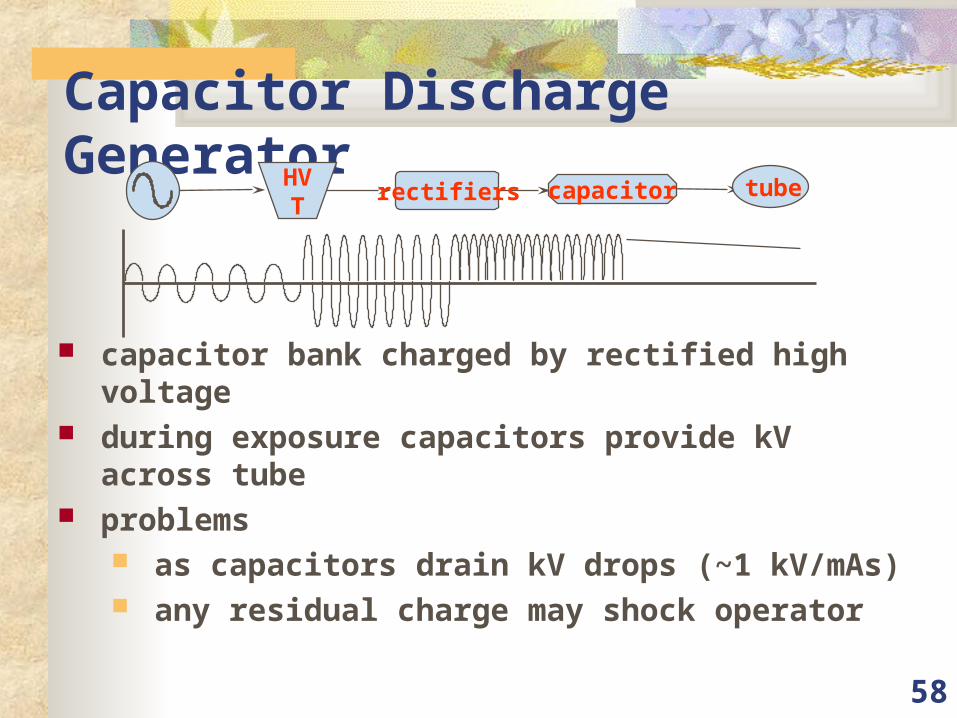
Capacitor Discharge Generator
capacitor bank charged by rectified high voltage during exposure capacitors provide kV across tube problems
as capacitors drain kV drops (~1 kV/mAs) any residual charge may shock operator
HVT
rectifiers capacitor tube
59
Falling-Load Generators
operates at shortest time + highest mA uses series of steps (mA + t) to achieve mAs
60
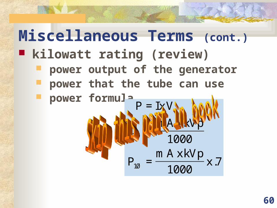
Miscellaneous Terms (cont.) kilowatt rating (review)
power output of the generator power that the tube can use power formula
P IxV
PmAxkVp
PmAxkVp
x
=
=
=
3
1
1000
10007
Ø
Ø .