Embed Size (px)
Citation preview
Booster Cogging
Bob Zwaska
University of Texas at Austin
Bill Pellico
FNAL
Bob Zwaska – University of Texas at AustinRun II Meeting – October 2, 2003
The Need for Cogging
• Booster beam has a notch in it– Extraction kicker risetime of ~ 40 ns– Bunch spacing of ~ 19 ns– 1-2 bunches of beam are lost on extracting– Notching the beam at 400 MeV involves less loss
• Requires extraction to be synchronized with the notch
• Extraction must also be synchronized to the beam already in the Main Injector
• Problem: The Booster and Main Injector are not synchronized.
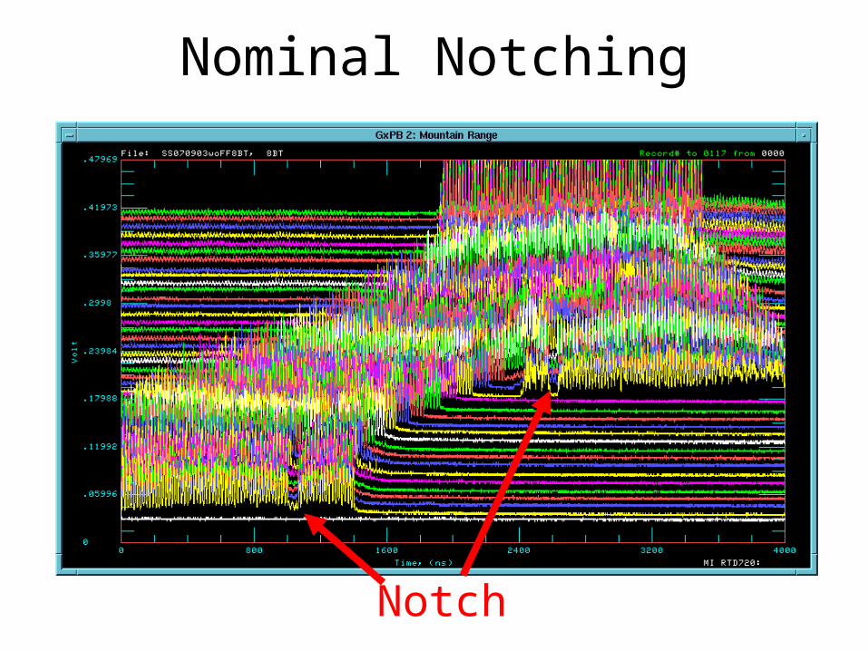
Nominal Notching
Notch
Bob Zwaska – University of Texas at AustinRun II Meeting – October 2, 2003
The Role of Cogging• Cogging will synchronize the Booster notch to
beam in the Main Injector• Necessary for any multibatch use of the Main
Injector– NuMI– Slip-stacking
• Booster has no flattop during which beam can be manipulated
• Cogging must be done during acceleration– Notch created anticipating slippage– Radial feedback corrects unanticipated slippage
Bob Zwaska – University of Texas at AustinRun II Meeting – October 2, 2003
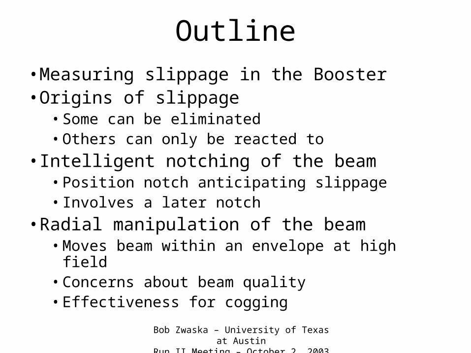
Outline• Measuring slippage in the Booster• Origins of slippage
• Some can be eliminated• Others can only be reacted to
• Intelligent notching of the beam• Position notch anticipating slippage• Involves a later notch
• Radial manipulation of the beam• Moves beam within an envelope at high field• Concerns about beam quality• Effectiveness for cogging
Bob Zwaska – University of Texas at AustinRun II Meeting – October 2, 2003
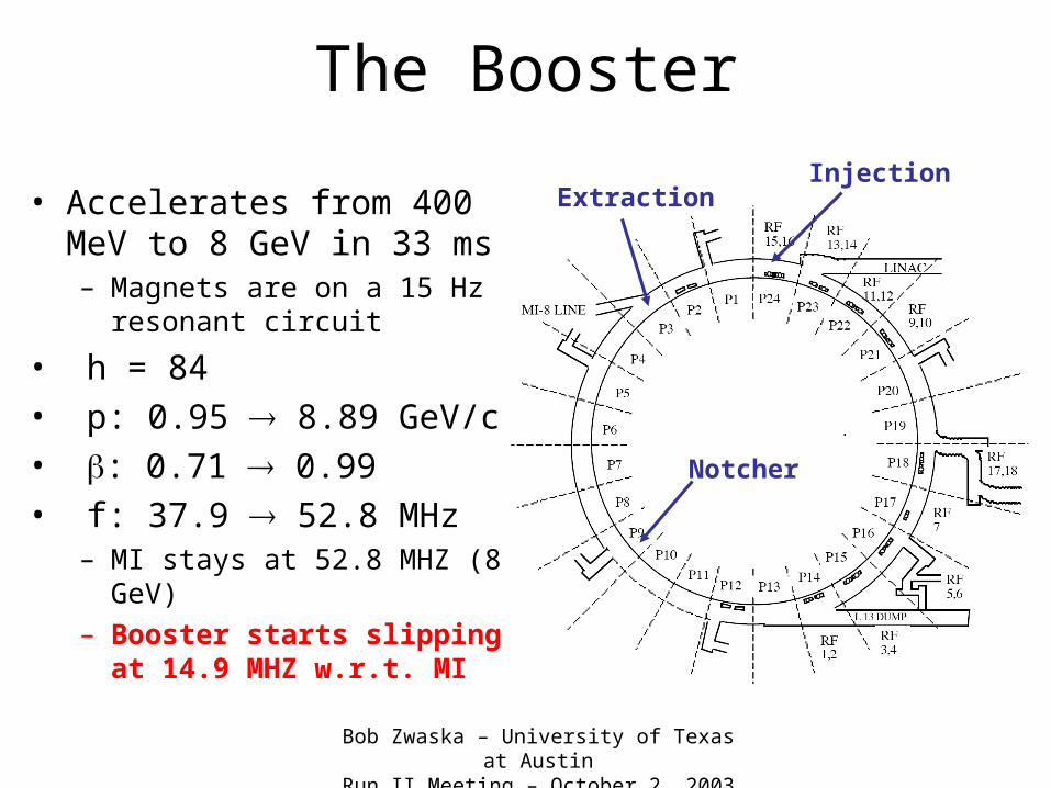
The Booster
• Accelerates from 400 MeV to 8 GeV in 33 ms– Magnets are on a 15 Hz
resonant circuit
• h = 84• p: 0.95 8.89 GeV/c • : 0.71 0.99• f: 37.9 52.8 MHz
– MI stays at 52.8 MHZ (8 GeV)
– Booster starts slipping at 14.9 MHZ w.r.t. MI
InjectionExtraction
Notcher
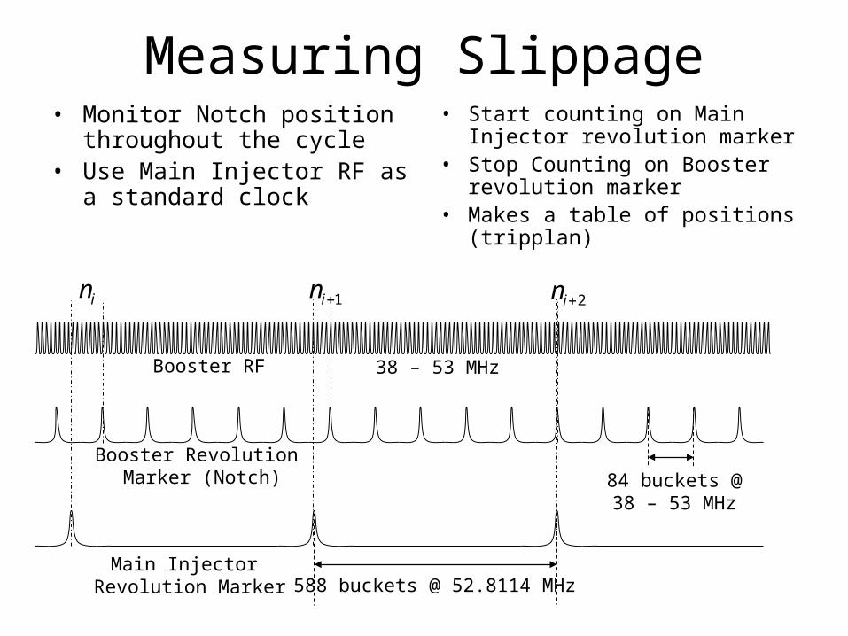
Measuring Slippage• Monitor Notch position
throughout the cycle• Use Main Injector RF as a
standard clock
• Start counting on Main Injector revolution marker
• Stop Counting on Booster revolution marker
• Makes a table of positions (tripplan)
588 buckets @ 52.8114 MHzMain Injector
Revolution Marker
84 buckets @38 – 53 MHz
Booster Revolution Marker (Notch)
Booster RF 38 – 53 MHz
in 1in 2in
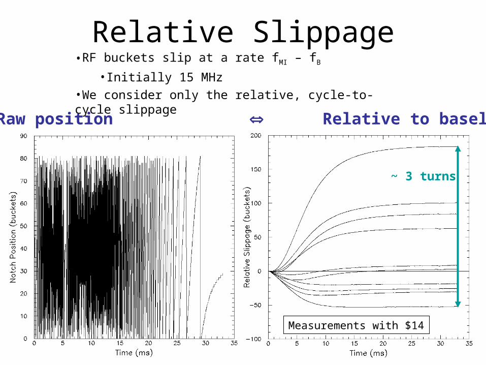
•RF buckets slip at a rate fMI – fB
•Initially 15 MHz
•We consider only the relative, cycle-to-cycle slippage
Raw position Relative to baseline
~ 3 turns
Relative Slippage
Measurements with $14
Bob Zwaska – University of Texas at AustinRun II Meeting – October 2, 2003
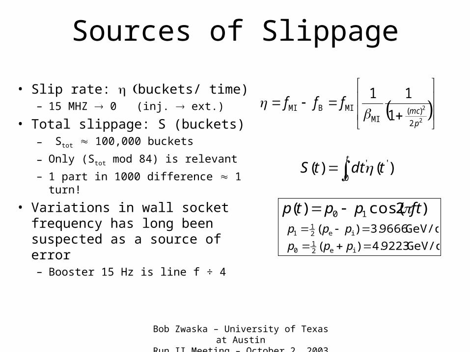
Sources of Slippage
• Slip rate: buckets/ time)– 15 MHZ 0 (inj. ext.)
• Total slippage: S (buckets)– Stot 100,000 buckets
– Only (Stot mod 84) is relevant
– 1 part in 1000 difference 1 turn!
• Variations in wall socket frequency has long been suspected as a source of error– Booster 15 Hz is line f ÷ 4
2
2
2
)(MI
MIBMI1
11
p
mcfff
t
tdttS0
'' )()(
)2cos()( 10 ftpptp
GeV/c 9223.4)( ie21
0 ppp
GeV/c 9666.3)( ie21
1 ppp
Bob Zwaska – University of Texas at AustinRun II Meeting – October 2, 2003
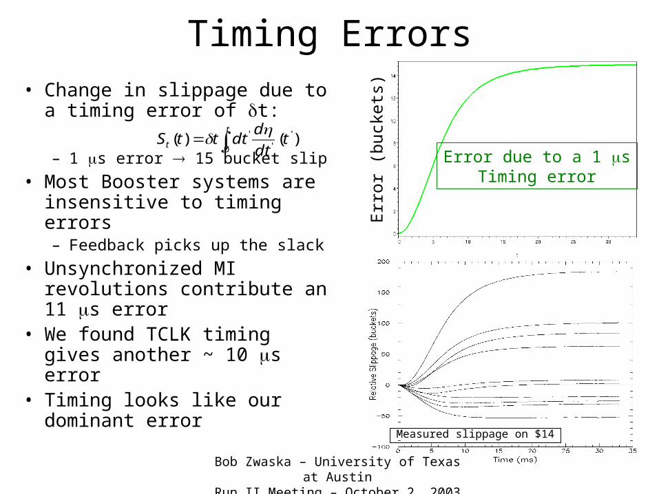
Timing Errors
• Change in slippage due to a timing error of t:
– 1 s error 15 bucket slip
• Most Booster systems are insensitive to timing errors– Feedback picks up the slack
• Unsynchronized MI revolutions contribute an 11 s error
• We found TCLK timing gives another ~ 10 s error
• Timing looks like our dominant error
t
t tdt
ddtttS
0
''
' )()(
Err
or (
buck
ets)
Error due to a 1 sTiming error
Measured slippage on $14
Bob Zwaska – University of Texas at AustinRun II Meeting – October 2, 2003
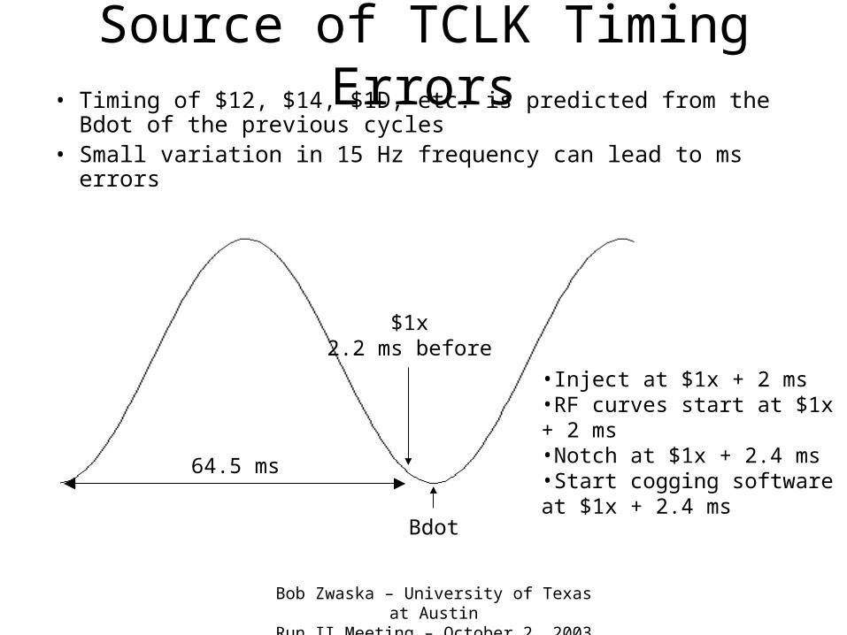
Source of TCLK Timing Errors• Timing of $12, $14, $1D, etc. is predicted from the Bdot
of the previous cycles• Small variation in 15 Hz frequency can lead to ms errors
$1x2.2 ms before
Bdot
64.5 ms
•Inject at $1x + 2 ms•RF curves start at $1x + 2 ms•Notch at $1x + 2.4 ms•Start cogging software at $1x + 2.4 ms
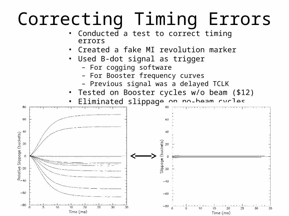
Correcting Timing Errors• Conducted a test to correct timing errors• Created a fake MI revolution marker• Used B-dot signal as trigger
– For cogging software– For Booster frequency curves– Previous signal was a delayed TCLK
• Tested on Booster cycles w/o beam ($12)• Eliminated slippage on no-beam cycles
Bob Zwaska – University of Texas at AustinRun II Meeting – October 2, 2003
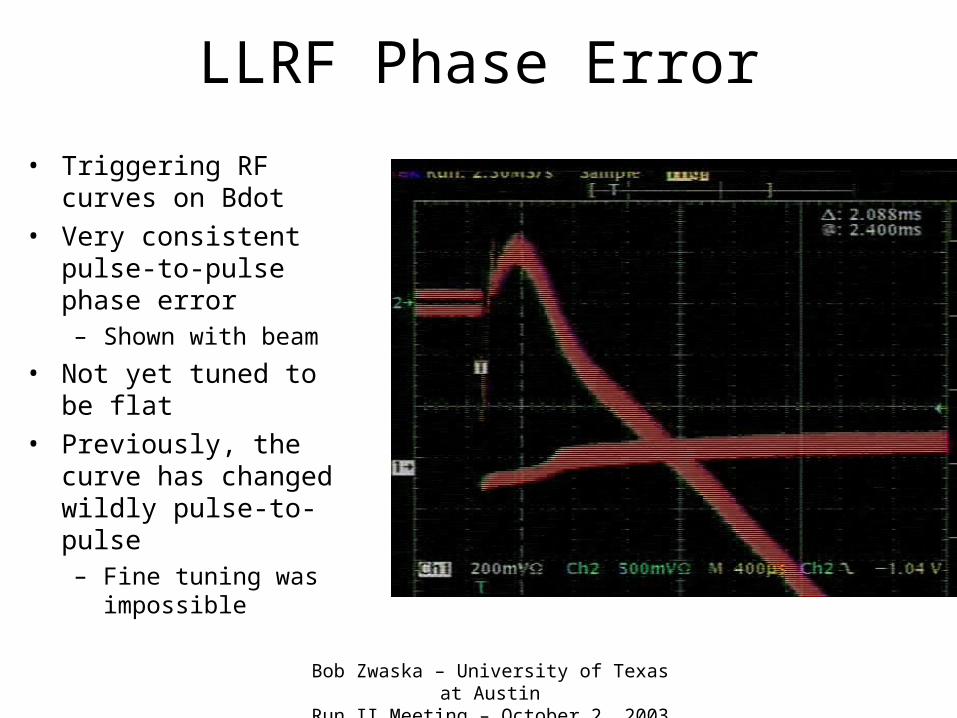
LLRF Phase Error
• Triggering RF curves on Bdot
• Very consistent pulse-to-pulse phase error– Shown with beam
• Not yet tuned to be flat• Previously, the curve
has changed wildly pulse-to-pulse– Fine tuning was
impossible
Bob Zwaska – University of Texas at AustinRun II Meeting – October 2, 2003
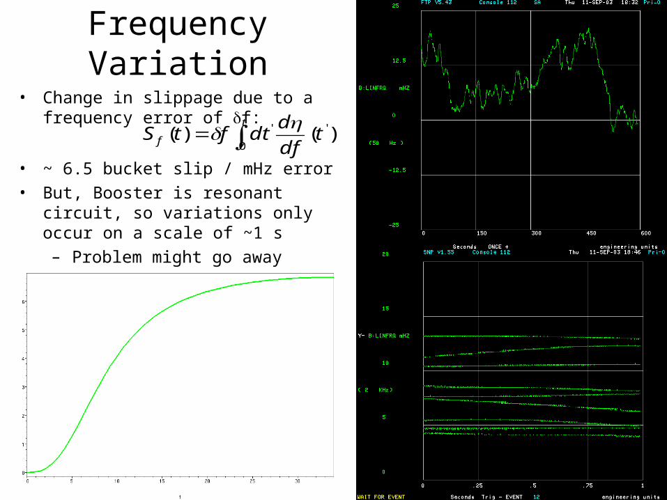
Frequency Variation
• Change in slippage due to a frequency error of f:
• ~ 6.5 bucket slip / mHz error
• But, Booster is resonant circuit, so variations only occur on a scale of ~1 s
– Problem might go away
t
f tdf
ddtftS
0
'' )()(
Bob Zwaska – University of Texas at AustinRun II Meeting – October 2, 2003
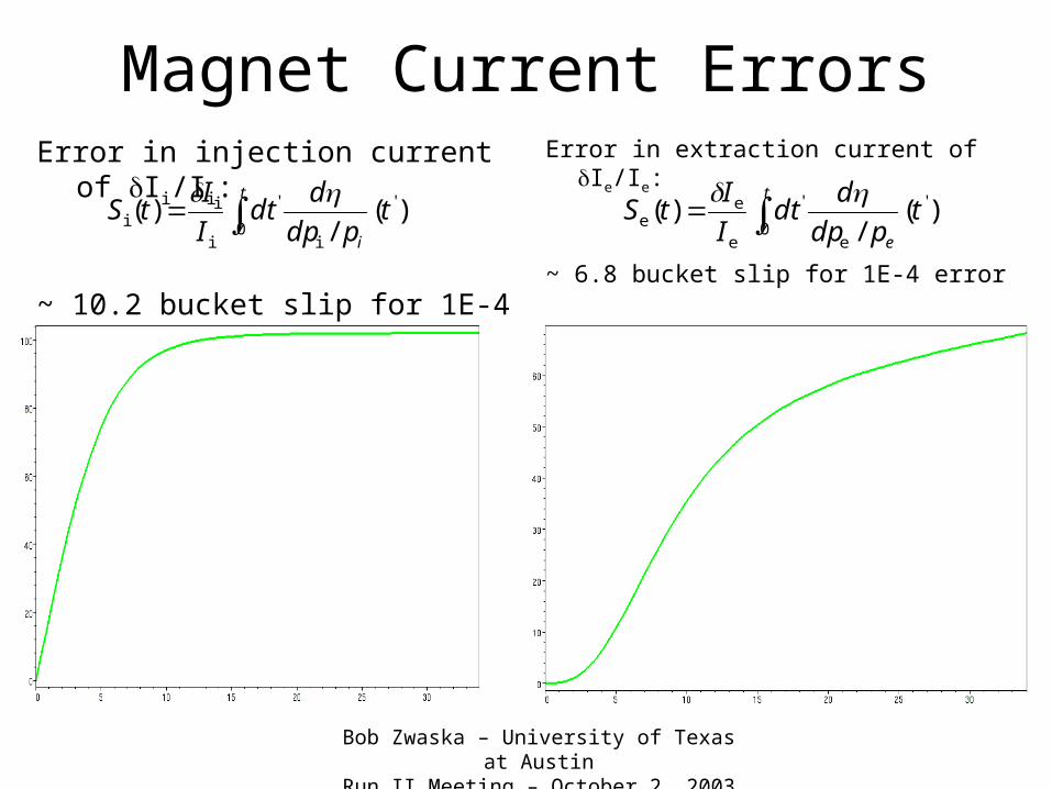
Magnet Current ErrorsError in injection current of Ii/Ii:
~ 10.2 bucket slip for 1E-4 error
Error in extraction current of Ie/Ie:
~ 6.8 bucket slip for 1E-4 error
t
e
tpdp
ddt
I
ItS
0
'
e
'
e
ee )(
/)(
t
i
tpdp
ddt
I
ItS
0
'
i
'
i
ii )(
/)(
Bob Zwaska – University of Texas at AustinRun II Meeting – October 2, 2003
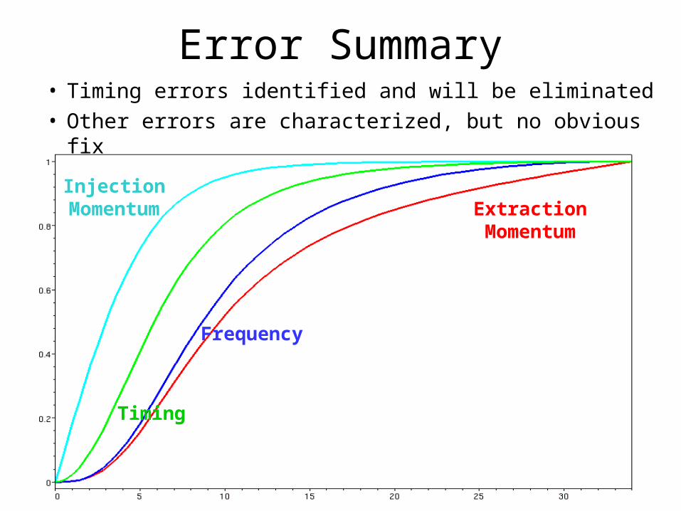
Error Summary• Timing errors identified and will be eliminated• Other errors are characterized, but no obvious fix
ExtractionMomentum
Frequency
Timing
InjectionMomentum
Bob Zwaska – University of Texas at AustinRun II Meeting – October 2, 2003
Cogging Method• Use first batch of multibatch as a baseline• Delay notch creation by 2-4 ms
– Sample relative slippage to make a slippage prediction– Make notch so that it ends up in the right position– Takes care of errors present at the beginning of the cycle (e.g.
timing)
• Change the beam’s radial position (RPOS)– Changes relative rate of slippage– Takes care of residual errors from the notch, and those that
occur after notch creation– Proof of Principle way back
• Pellico & Webber – IEEE PAC 1999• Showed that slippage could be controlled by changing radial
position
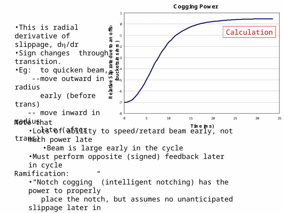
Cogging Power
-8
-7
-6
-5
-4
-3
-2
-1
0
1
0 5 10 15 20 25 30 35
Time (ms)
Re
lati
ve
Slip
ra
te d
ue
to
an
off
se
t (b
uc
ke
ts/m
s/m
m)
•This is radial derivative of slippage, d/dr•Sign changes through transition.•Eg: to quicken beam, --move outward in radius early (before trans) -- move inward in radius late (after trans)
Note that•Lots of ability to speed/retard beam early, not much power late
•Beam is large early in the cycle•Must perform opposite (signed) feedback later in cycle
Ramification:•“Notch cogging” (intelligent notching) has the power to properly place the notch, but assumes no unanticipated slippage later in
Booster cycle (>5ms)•“Radial cogging” can be performed later in cycle to correct any imperfections in notch cogging.
Calculation
sample
Notch
radial feedback
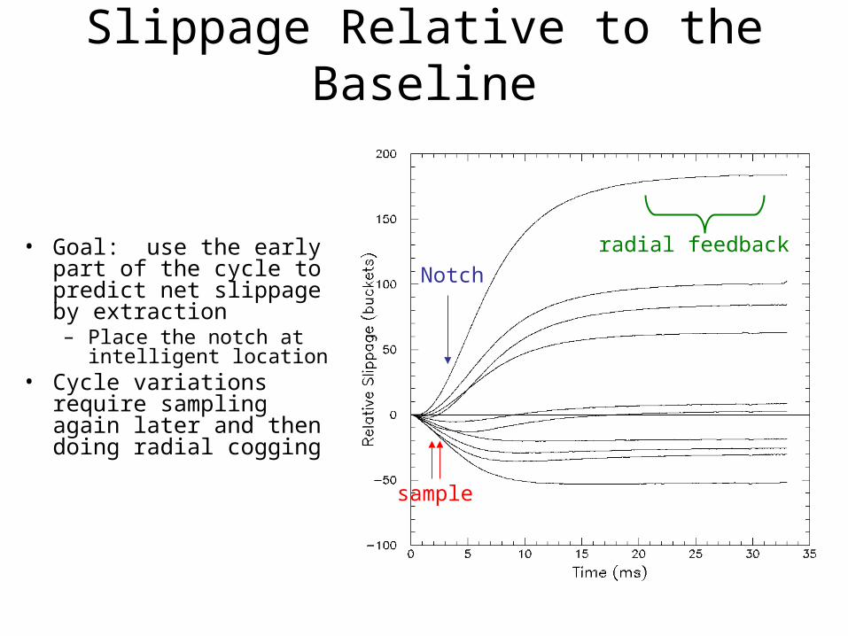
Slippage Relative to the Baseline
• Goal: use the early part of the cycle to predict net slippage by extraction – Place the notch at
intelligent location• Cycle variations require
sampling again later and then doing radial cogging

Intelligent Notching• Reduces spread of notch positions
– Factor of 3-4
• The rest is left for radial feedback
Notch position at extraction vs. MI marker
Bob Zwaska – University of Texas at AustinRun II Meeting – October 2, 2003
Delayed Notch• Current notch at 0.4 ms; E 400 MeV
– Delay 3-4 ms for cogging
• Need to know notch can be made
• Loss ramifications (from notching)– In principle, losses increase:
• 35% with 3 ms (550 MeV) • 65% with 4 ms (660 MeV)
– But, where do they go?
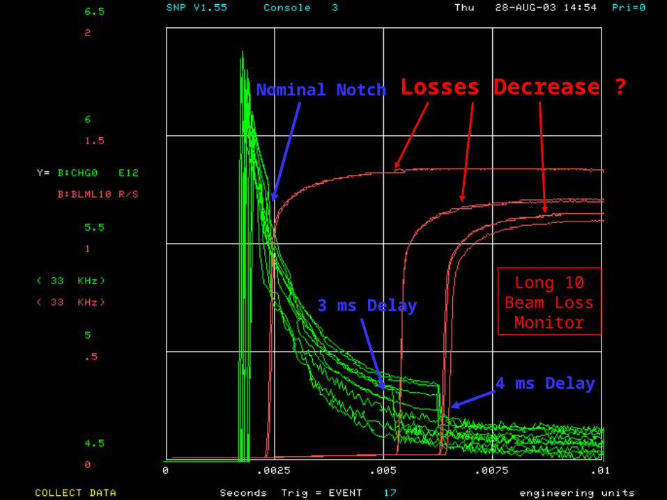
Losses Decrease ?
Long 10Beam Loss
Monitor
Nominal Notch
3 ms Delay
4 ms Delay
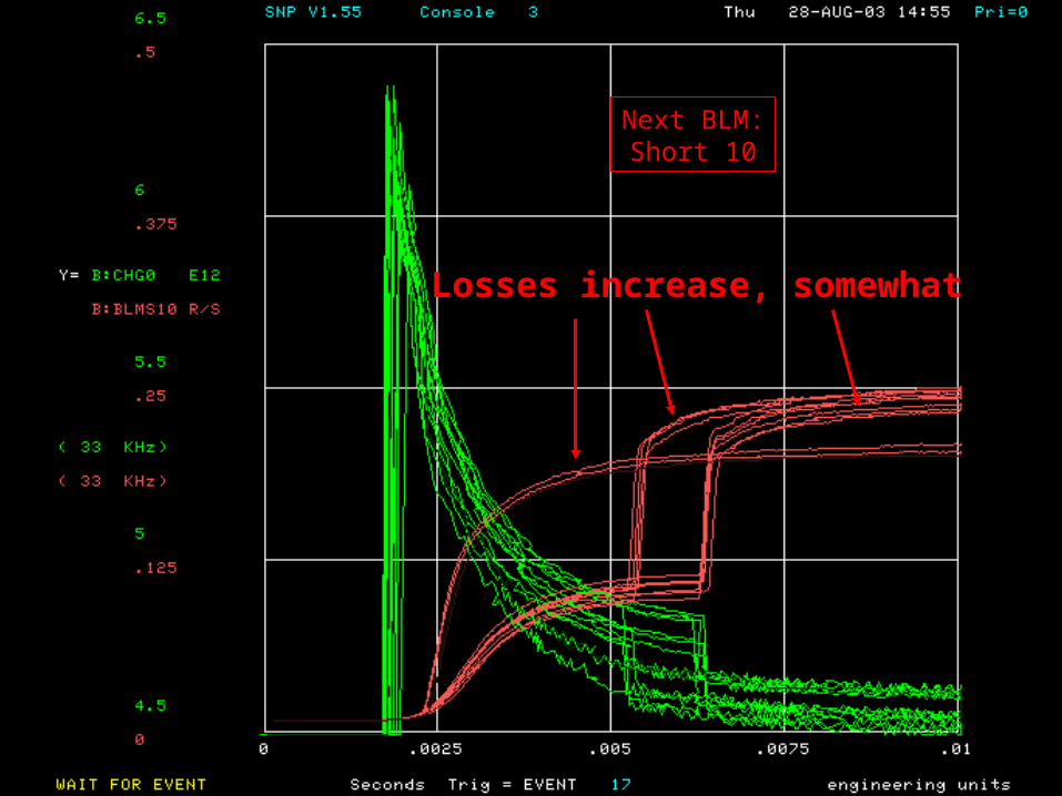
Losses increase, somewhat
Next BLM:Short 10
Bob Zwaska – University of Texas at AustinRun II Meeting – October 2, 2003
Delayed Notch
• Kicker strength– Good at a delay of 3 ms– Voltage needed to be bumped up at 4 ms
• Losses spread downstream– Long 10 losses actually decreased
• New notching schemes– Take advantage of collimators– Might allow more flexibility
Bob Zwaska – University of Texas at AustinRun II Meeting – October 2, 2003
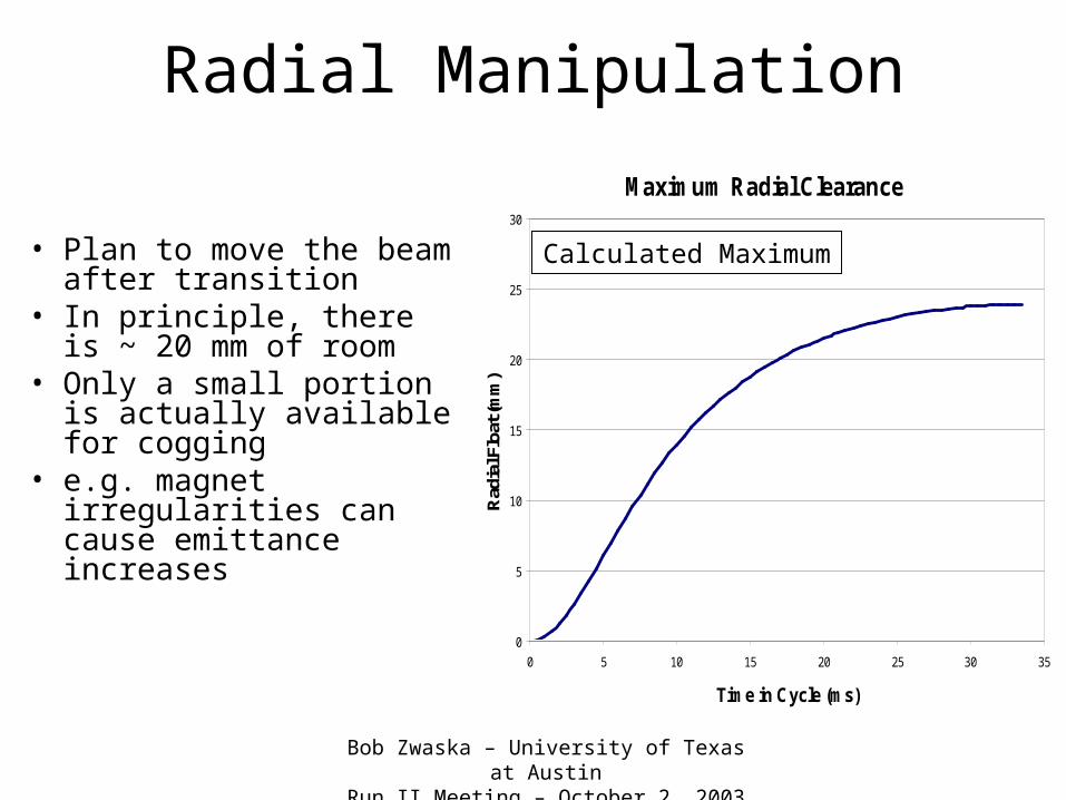
Radial Manipulation
• Plan to move the beam after transition
• In principle, there is ~ 20 mm of room
• Only a small portion is actually available for cogging
• e.g. magnet irregularities can cause emittance increases
Maximum Radial Clearance
0
5
10
15
20
25
30
0 5 10 15 20 25 30 35
Time in Cycle (ms)
Rad
ial F
loat
(mm
)
Calculated Maximum
Bob Zwaska – University of Texas at AustinRun II Meeting – October 2, 2003
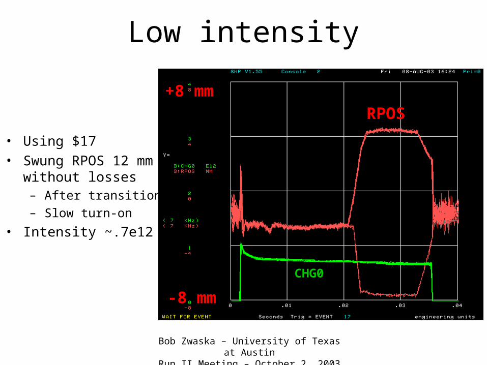
Low intensity
• Using $17• Swung RPOS 12 mm
without losses– After transition
– Slow turn-on
• Intensity ~.7e12
RPOS
-8 mm
+8 mm
CHG0
Bob Zwaska – University of Texas at AustinRun II Meeting – October 2, 2003
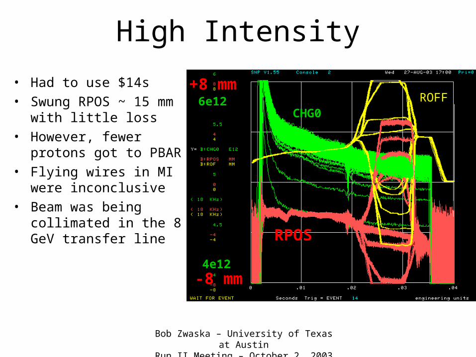
High Intensity
• Had to use $14s• Swung RPOS ~ 15 mm
with little loss• However, fewer protons
got to PBAR• Flying wires in MI were
inconclusive• Beam was being
collimated in the 8 GeV transfer line RPOS
-8 mm
+8 mm
CHG0
4e12
6e12 ROFF
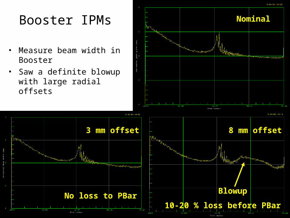
Booster IPMs
• Measure beam width in Booster
• Saw a definite blowup with large radial offsets
Nominal
3 mm offset 8 mm offset
BlowupNo loss to PBar
10-20 % loss before PBar
Bob Zwaska – University of Texas at AustinRun II Meeting – October 2, 2003
Radial Conclusion
• ±4 mm of radial motion causes little problem (after transition)– Allows correction of ~ 20 buckets worth of error
• Larger offsets do not cause losses in the Booster– But, beam is lost upstream of the Booster
• Tests will have to be redone after the shutdown– New lattice– Beam surviving injection will be different– Collimators
Bob Zwaska – University of Texas at AustinRun II Meeting – October 2, 2003
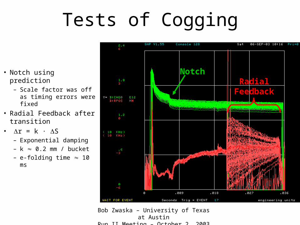
Tests of Cogging
• Notch using prediction– Scale factor was off as
timing errors were fixed
• Radial Feedback after transition
• r = k ∙ S– Exponential damping– k 0.2 mm / bucket– e-folding time 10 ms
NotchRadial
Feedback
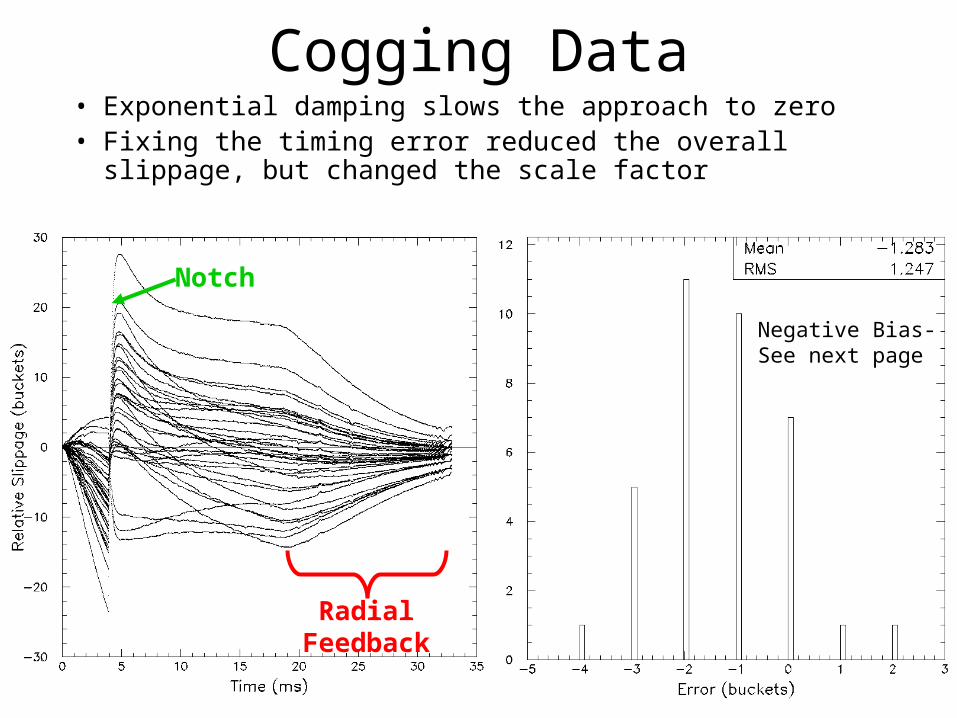
Cogging Data• Exponential damping slows the approach to zero• Fixing the timing error reduced the overall slippage,
but changed the scale factor
Notch
RadialFeedback
Negative Bias-See next page
Bob Zwaska – University of Texas at AustinRun II Meeting – October 2, 2003
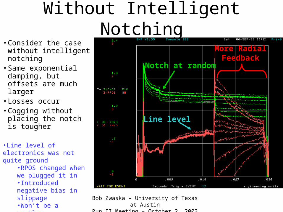
Without Intelligent Notching• Consider the case
without intelligent notching
• Same exponential damping, but offsets are much larger
• Losses occur• Cogging without placing
the notch is tougher
Notch at random
More RadialFeedback
Line level
•Line level of electronics was not quite ground
•RPOS changed when we plugged it in•Introduced negative bias in slippage•Won’t be a problem
Bob Zwaska – University of Texas at AustinRun II Meeting – October 2, 2003
Cogging Summary
• Intelligent notching cuts down the needed correction– Scale factor needs to be reexamined
• Timing losses eliminated
– Notch time needs to be a bit earlier
• Feedback works as expected– Can start a few ms earlier– RPOS turn-on will need to be gradual– Damping needs to be faster than exponential
Bob Zwaska – University of Texas at AustinRun II Meeting – October 2, 2003
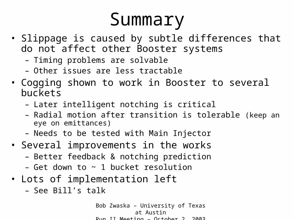
Summary• Slippage is caused by subtle differences that do not affect
other Booster systems– Timing problems are solvable– Other issues are less tractable
• Cogging shown to work in Booster to several buckets– Later intelligent notching is critical – Radial motion after transition is tolerable (keep an eye on emittances)
– Needs to be tested with Main Injector
• Several improvements in the works– Better feedback & notching prediction– Get down to ~ 1 bucket resolution
• Lots of implementation left– See Bill’s talk