Embed Size (px)
DESCRIPTION
Manual
Citation preview
DESCRIPTION AND OPERATING INSTRUCTIONS FOR THE
BACK-FLUSHING FILTER TYPE 6.61.07====================================================================
Commission No.
C O N T E N T S
1. Type Sheet 6.61.07
Description of the Flushing Oil Regeneration Unit
2. General Information on the Automatic Filter
3. Filter Installation
4. Commissioning
5. Filtration Phase
6. Back-Flushing Operation
7. Description of the EL.-Control System
8. Circuit Diagram
9. Equipment List for EL.-Control System
10. Servicing
11. Servicing Tools
12. Cleaning Agents for Candle Elements
13. Manuel Cleaning of Candle Elements
14. Manual operation of the automatic filter
15. Spare Part Drawing for Type 6.61
16. Spare Part List for Type 6.61
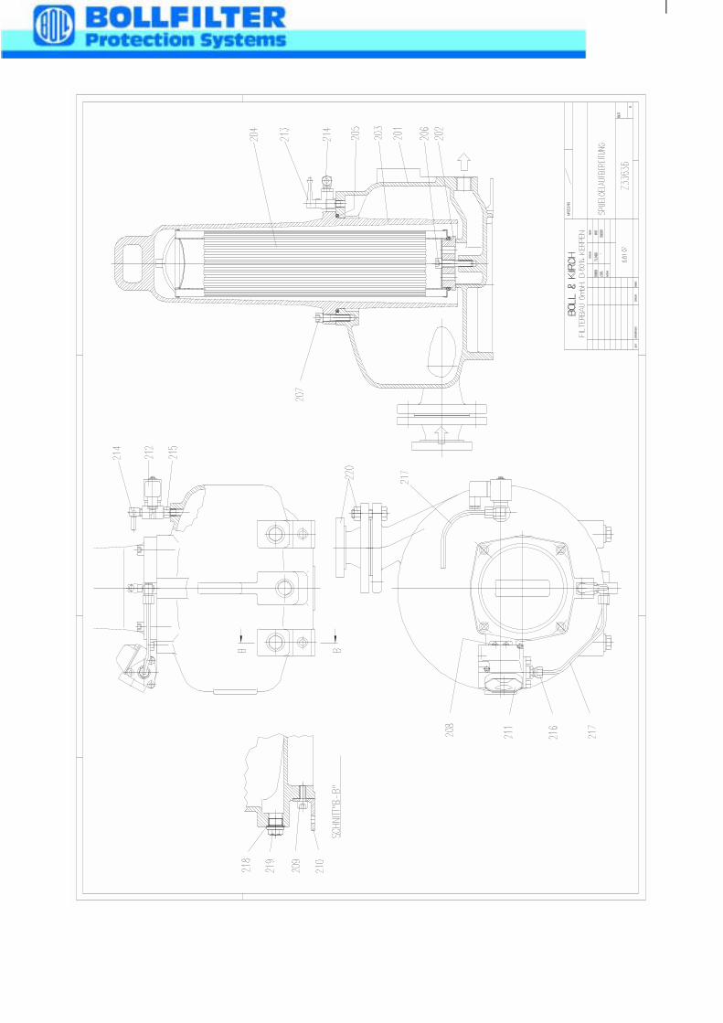
17. Spare Part Drawing for Flushing Oil Regeneration Unit
18. Spare Part List for Flushing Oil Regeneration Unit
19. Type Sheet for the Differential Pressure Indicator with Electrical Contacts
20. Spare Part Drawing for the Differential Pressure Indicator
BOLL & KIRCH assumes no liability for any mistakes by any misuse of the product.We reserve the right to change this description without any prior notice!
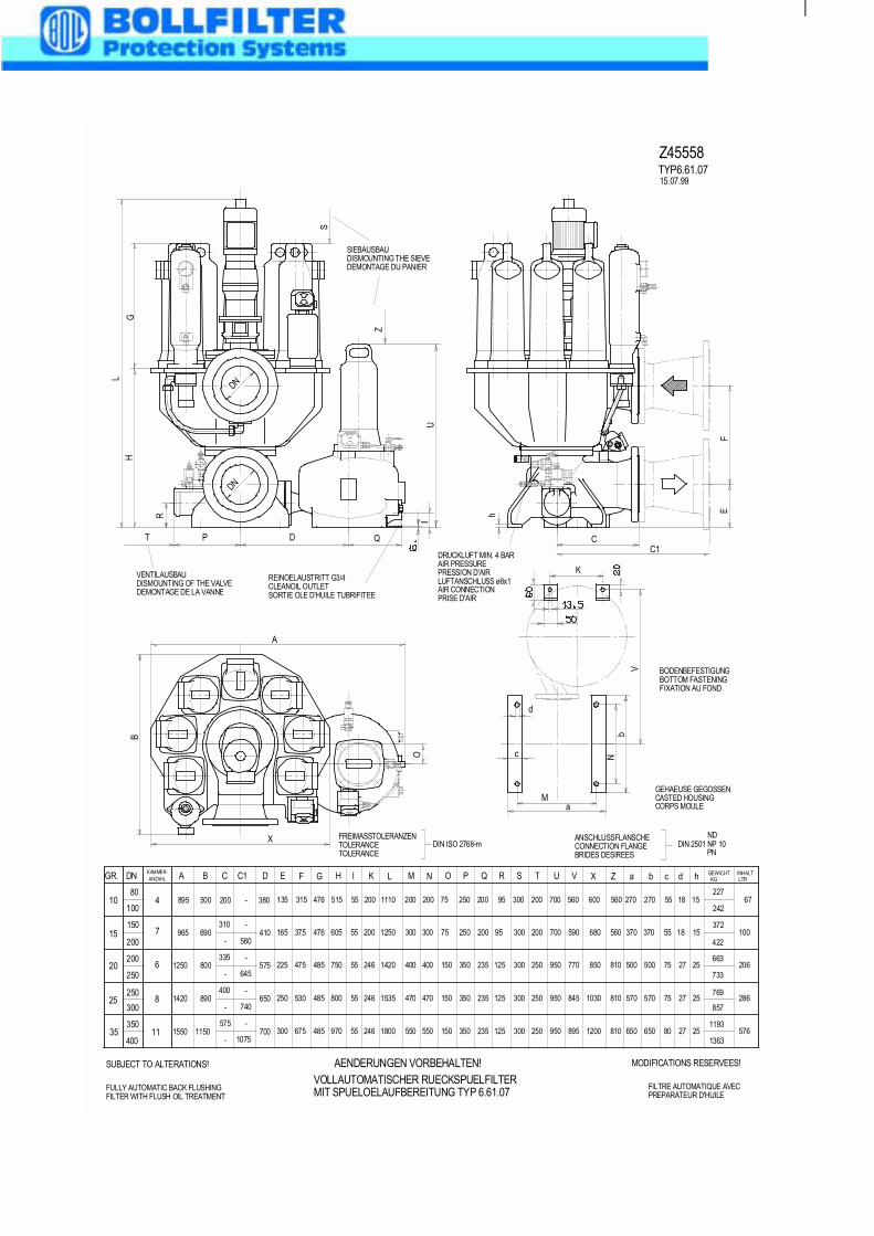
BODENBEFESTIGUNGBOTTOM FASTENINGFIXATION AU FOND
GEHAEUSE GEGOSSENCASTED HOUSINGCORPS MOULE
ANSCHLUSSFLANSCHECONNECTION FLANGEBRIDES DESIREES
DIN 2501 NP 10ND
PN
FREIMASSTOLERANZENTOLERANCETOLERANCE
DIN ISO 2768-m
VENTILAUSBAUDISMOUNTING OF THE VALVEDEMONTAGE DE LA VANNE
REINOELAUSTRITT G3/4CLEANOIL OUTLETSORTIE OLE D'HUILE TUBRIFITEE
SIEBAUSBAUDISMOUNTING THE SIEVEDEMONTAGE DU PANIER
DRUCKLUFT MIN. 4 BARAIR PRESSUREPRESSION D'AIRLUFTANSCHLUSS ø8x1AIR CONNECTIONPRISE D'AIR
TYP6.61.0715.07.99
SUBJECT TO ALTERATIONS! MODIFICATIONS RESERVEES!AENDERUNGEN VORBEHALTEN!
DN A B C D E F G H L M N P R S T hdKAMMER-ANZAHL
4
6
8
80
100
150
200
250
895 500 200 380 135 315 476 515 1110 200 200 250 95 300 200 1518
1250 800335
575 225 475 485 750 1420 400 400 350 125 300 250 2527
10
15
20
200
250
25300
7
C1
645
GR.
965 690310
410 375 476 605 1250 300 300 250 95 300 200 1518165580
1420 890400
650 250 530 485 800 1535 470 470 350 125 300 250 2527740
X Z
600 560
850 810
680 560
1030 810
a b
270 270
500 500
370 370
570 570
c
55
75
55
75
1135350
1550 1150 700 300 675 485 970 1800 550 550 350 125 300 250 2527575
1200 810 650 650 80
-
-
-
-
-
-
-
-
1075-
67
206
100
286
576
227
372
663
769
422
733
857
1193
1363
242
GEWICHT KG
INHALT LTR
400
I
55
55
55
55
55
K
200
246
200
246
246
O
75
150
75
150
150
Q
200
235
200
235
235
U
700
950
700
950
950
V
560
770
590
845
895
FULLY AUTOMATIC BACK FLUSHINGFILTER WITH FLUSH OIL TREATMENT
FILTRE AUTOMATIQUE AVECPREPARATEUR D'HUILE
VOLLAUTOMATISCHER RUECKSPUELFILTERMIT SPUELOELAUFBEREITUNG TYP 6.61.07
A
B
C1D
EF
GH
L
I
S
Z
T P Q
U
h
O
X
DN
DN
R
C
V
M
N
K
a
b
c
d
Z45558
Description of flushing-oil processing systems(see drawing Z 33703 pages 1 + 2 for Type 6.60.07)(see drawing Z 33701 pages 1 + 2 for Type 6.61.07)
General information
The fully-automated back-flushing filter with the flushing-oil processing system is ideally
suited for filtration of fuels and lubricating oils.
In the flushing-oil processing system, liquid flushed back from out of the filter system is
generated.
The filter elements of the back-flushing filter are cleaned automatically and without any
interruption in operation, by back flushing by means of compressed air (please revfer to
separate description).
The filter element for flushing-oil processing is a cartridge which has to be replaced by a
new cartridge affter it has become saturated.
The flushing-oil processing system consists mainly of the following components:
Casing with inlet and outlet;
Filter chamber;
Filter element;
Solenoid valve;
Differential pressure indicator.
N.B.:
An air supply is nedded for correct operation of the flushing-oil processing system (3-7
bars). This air supply is connected to the solenoid valve and is already installed by the
works, if the flushing-oil processing system is fitted.
Mode of operation
During back-flushing from the filtrations system, the back-flushing liquid reaches the non-
pressurised flushing-oil processing system. Once the filter flushing process is complete
and the sludge outlet has closed, then the solenoid valve (which is connected to the
flushing-oil processing system) is activated and switches over.
The supply of compressed air then reaches the flushing-oil processing system and forces
the flow medium through the flushing cartridge, whereafter it reaches the outlet flange in a
clean condition.
The dirt particles retained at the flushing-oil cartridge cause an increasing differential
pressure between the inlet and the outlet. On attainment of the maximum premissible
value in this differential pressure, the differential pressure indicator gives a visual
indication for the flushing-oil processing system and a zero-voltage alarm is set off.
If this alarm continues to sound uninterruptedly for more than 2 minutes, then the flushing-
oil cartridge must be replaced by a clean cartridge.
N. B.:
In order to ensure correct filter operation, it is absolutely essential that alarms be
connected and acted upon at the installation premises. The back-flushing filtration function
will be disrupted if the alarms are ignored.
The capacity of the flushing-oil cartridge to absorb dirt can be exploited to the maximum
only if it is ensured that the flushing-oil cartridge is replaced after 2 minutes constant
alarm.
2. General
The fully automatic back-flushing filter is used to filter a variety of fluids, but chiefly
for the filtration of fuels, lubricating oils, caustic solutions and emulsions. The filter
elements semblies are cleaned automatically by compressed air assisted back-
flushing without interrupting the filtration process. One clean chamber is always
held in reserve.
This self-cleaning filter consists basically of the following parts:
The lower housing with connection flange for filter outlet and connection flange for
the removal of flushing fluid (sludge discharge).
The change-over system housing with the filter inlet, on which the filter chambers
containing the candle elements and the automatic vent are set out. In the centre of
the housing is the stop plug with refill bore.
The geared motor.
The air supply with non-return valve, shutt-off valve and pressure regulator.
The safety valve.
The differential pressure indicator Δp1.
The flushing valve with manual actuation.
The limit switch.
The EL.-control system in its own switch box separate from the filter.
3. Installation of the Filter
Care must be taken during installation of the filter that the pipelines attached to the
filter inlet and outlet are clean and not under tension.
The pipeline selcted for the sludge discharge is to be no smaller than the size
indicated on the type sheet. To avoid back-pressure arising in the pipe, it is to be
laid on a gradient and vented.
The terminal board on the filter is to be connected to the terminal board in the
switch cabinet by means of the control system cable (see circuit diagram).
When the filter is used in aqueous media, it is imperative to observe the following:
3.1 It must be ensured that the filter does not run dry even after the supply
pump has been switched off (owing to hardening of dirt).
3.2 If this condition cannot be fulfilled, at least the EL.- control must be
designed so that, even when the supply pump is switched off, back-
flushing is initiated every 2 hours by a time relay.
Flushing operations into a completely empty chamber for test
purposes are permitted without any restrictions. Flushing into a
partially filled chamber results in increased loading of the filter
candles. Back-flushing for installation (pipe) or control reasons into
a filter chamber which is only partially filled is therefore
inadmissible.
The filter housings are only designed for internal overpressure in
accordance with the AD Information Sheets. Additional external
forces and moments at the filter connection flanges are to be
avoided (possibly by supporting the supply lines).
When installing the filters, make sure that any oil or fuel which
leaks due to improper handling cannot result in a fire or injury.
4. CommissioningThe following requirements must be met for the commissioning of the filter:
4.1 Clean and dry compressed air for the control system at between 4 and
10 bar operating pressure, must be available at the open shut-off valve.
4.2 Switch on the electricity using the "Main Switch" on the switch box. The
"Power" lamp respectively LED-operating display lights up. (Activation of
the main switch initiates a back-flushing cycle.)
4.3 To check the EL.- control system a back-flushing cycle should now be
performed by activating the "Manual" trip on the switch box.
4.4 Open the slide valve at the filter outlet. Slowly open the slide valve at the
filter inlet (avoiding pipe hammer). A further back-flushing cycle is to be
performed using the Manual trip on the switch box. Once the back-
flushing operation is completed, the "Flushing" respectively the display
"SP.1" lamp goes out. If these conditions are met, the filter is in the start
position and is therefore ready for operation.
NOTE: Possible time interval calculation for time-dependent back-flushing
Let the filter run for 24 hours using the differential pressure and establish the
number of back-flushing operations (flushing cycle counter or display).
Calculate the average flushing interval.
Set the flushing interval (shortened by 30%) on the time relay or PA.2.
After completion of a back-flushing cycle, the next backflushing
operation can only be intiated (manually or by means of the
differential pressure indicator) after a time delay.
This time delay corresponds to the time preset on the time relay
"K1A" or the preselected time "PA.5" in the electronic control. It is
needed to guarantee that the cleaned filter chamber is filled.
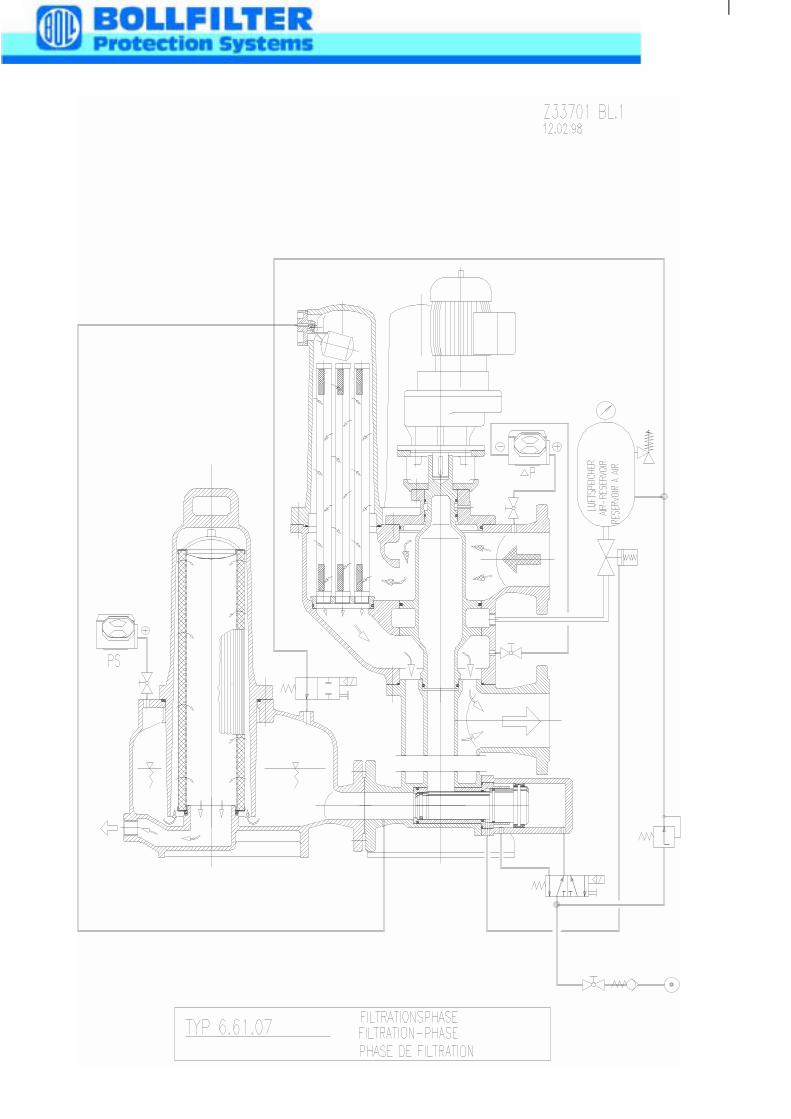
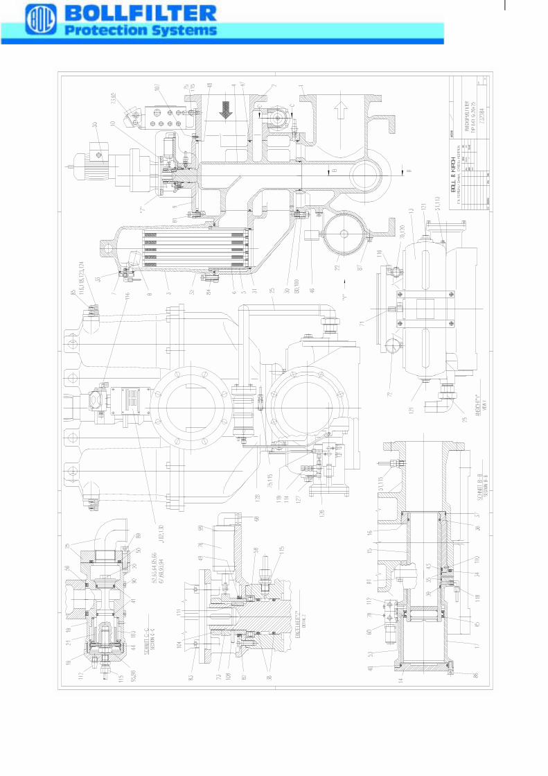
5. Filtration Phase(see Drawing Z 32326 p. 1 or Z 33701 p. 1)
The medium to be filtered flows down into the change-over system housing and
passes from there through the chamber inlet and the connected filter chambers to
the candle elements. The medium flows through the filter elements from the outside
to the inside and the contamination in the medium is retained on the filter mesh of
the candle elements. The cleaned fluid passes to the filter outlet.
In this position the air supply (by means of the solenoid valve) keeps the sludge
discharge closed and compressed air is maintained in the air receiver ready for
the next backflushing cycle.
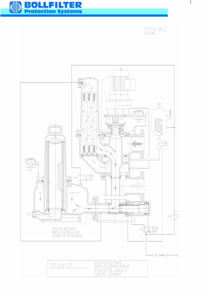
6. Back-Flushing Operation (See Drawing Z32326 p. 2 or Z33701 p. 2)
The contamination retained on the candle elements produces an increasing
pressure differential between the filter inlet and outlet. This difference in pressure is
indicated optcally on the differential pressure indicator when a set value is reached
and an electrical contact triggers the back-flushing.
When the back-flushing cycle is initiated, the geared motor is switched on and the
change-over plug rotates from the chamber held in reserve to the filter chamber to
be cleaned. Connection of the reserve chamber, together with its clean candle
elements, causes an immediate reduction in the pressure differential. When the
stop plug reaches the filter chamber to be cleaned the rotation is stopped by means
of a cam plate and a limit switch.
The solenoid valve (from the sludge discharge) is then switched electrically and air
from the air supply passes to the rear side of the sludge discharge valve shaft. The
sludge discharge valve opens and pressure is released from the chamber now shut
off. (See Note!)
While the sludge discharge valve shaft is opening, the control system air reaches
the attached flushing valve (once the pressure has been released on the filter
chamber). The flushing valve opens and the compressed air from the air receiver
dispatches the clean fluid present and pushes it in the counter current direction
through the mesh of the screw-in candle elements.
This allows the compressed air in the upper region of the plug to
immediately expand and thus creates additional space for the fluid
displaced (by the air) in the backflushing cycle.
The pressure drop thus generated flushes off the contamination deposited on the
mesh and washes it out of the filter housing via the open sludge discharge valve.
The air flow is continued for a short period (flushing period) before the solenoid
valve is electrically switched over, causing the sludge discharge valve to close. At
the same time the flow of air from the control system to the connected flushing
valve is interrupted and thus also stops the flow of the stored back-flushing air. The
backflushed filter chamber is now refilled with clean medium through the refill bore
until operating pressure is achieved.
Only then is the delay of the electric control cancelled for the next back-flushing
operation.
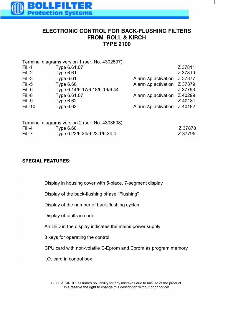
ELECTRONIC CONTROL FOR BACK-FLUSHING FILTERSFROM BOLL & KIRCH
TYPE 2100
Terminal diagrams version 1 (ser. No. 4302597):Fil.-1 Type 6.61.07 Z 37811Fil.-2 Type 6.61 Z 37810Fil.-3 Type 6.61 Alarm Δp activation Z 37877Fil.-5 Type 6.60 Alarm Δp activation Z 37879Fil.-6 Type 6.14/6.17/6.18/6.19/6.44 Z 37793Fil.-8 Type 6.61.07 Alarm Δp activation Z 40299Fil.-9 Type 6.62 Z 40181Fil.-10 Type 6.62 Alarm Δp activation Z 40182
Terminal diagrams version 2 (ser. No. 4303608):Fil.-4 Type 6.60 Z 37878Fil.-7 Type 6.23/6.24/6.23.1/6.24.4 Z 37795
SPECIAL FEATURES:
· Display in housing cover with 5-place, 7-segment display
· Display of the back-flushing phase "Flushing"
· Display of the number of back-flushing cycles
· Display of faults in code
· An LED in the display indicates the mains power supply
· 3 keys for operating the control
· CPU card with non-volatile E-Eprom and Eprom as program memory
· I.O. card in control box
BOLL & KIRCH assumes no liability for any mistakes due to misuse of the product.We reserve the right to change this description without prior notice!
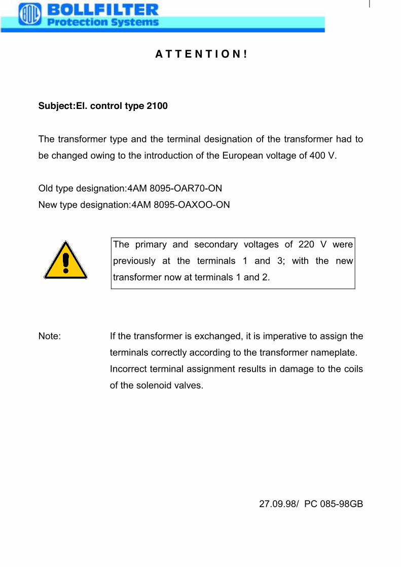
A T T E N T I O N !
Subject:El. control type 2100
The transformer type and the terminal designation of the transformer had to
be changed owing to the introduction of the European voltage of 400 V.
Old type designation:4AM 8095-OAR70-ON
New type designation:4AM 8095-OAXOO-ON
Note: If the transformer is exchanged, it is imperative to assign the
terminals correctly according to the transformer nameplate.
Incorrect terminal assignment results in damage to the coils
of the solenoid valves.
27.09.98/ PC 085-98GB
The primary and secondary voltages of 220 V were
previously at the terminals 1 and 3; with the new
transformer now at terminals 1 and 2.
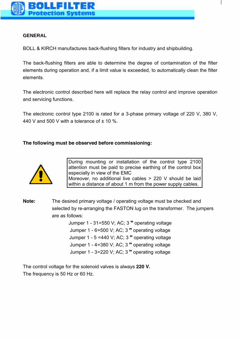
GENERAL
BOLL & KIRCH manufactures back-flushing filters for industry and shipbuilding.
The back-flushing filters are able to determine the degree of contamination of the filterelements during operation and, if a limit value is exceeded, to automatically clean the filterelements.
The electronic control described here will replace the relay control and improve operationand servicing functions.
The electronic control type 2100 is rated for a 3-phase primary voltage of 220 V, 380 V,440 V and 500 V with a tolerance of ± 10 %.
The following must be observed before commissioning:
Note: The desired primary voltage / operating voltage must be checked andselected by re-arranging the FASTON lug on the transformer. The jumpersare as follows:
Jumper 1 - 31=550 V; AC; 3 ! operating voltageJumper 1 - 6=500 V; AC; 3 ! operating voltageJumper 1 - 5 =440 V; AC; 3 ! operating voltageJumper 1 - 4=380 V; AC; 3 ! operating voltageJumper 1 - 3=220 V; AC; 3 ! operating voltage
The control voltage for the solenoid valves is always 220 V.The frequency is 50 Hz or 60 Hz.
During mounting or installation of the control type 2100attention must be paid to precise earthing of the control boxespecially in view of the EMCMoreover, no additional live cables > 220 V should be laidwithin a distance of about 1 m from the power supply cables.
The power supply line is laid to terminals 1, 2 and 3 with 3-phase voltage.
The protective earth conductor "PE" of the power supply line must be laid to the 10-pin
"PE" terminal strip or to the earth screw inside the control box.
Now all the electric components on the filter are to be wired according to the relevant
wiring diagram.
Note: The control is designed for a max. rated current of 1.0 A - and a starting
current of 3.0 A . Therefore, the control is unsuitable for a 1-phase operating
voltage network.
COMMISSIONING OF THE ELECTRONIC CONTROL
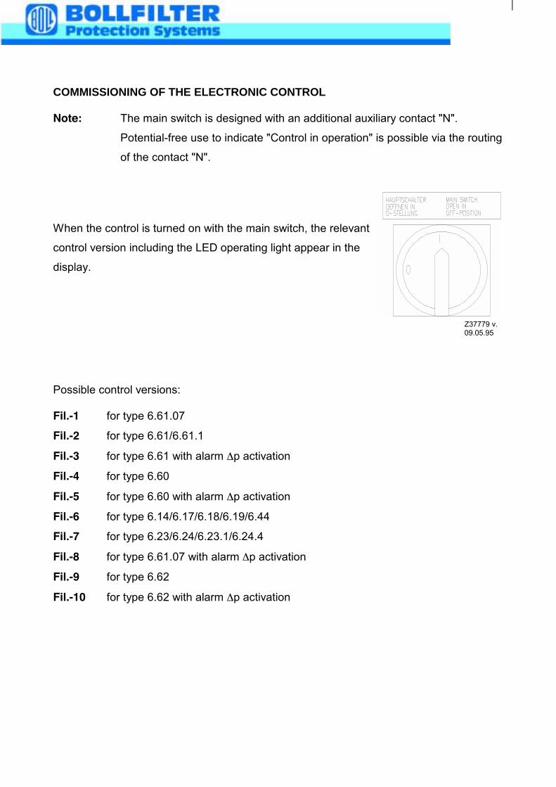
Note: The main switch is designed with an additional auxiliary contact "N".
Potential-free use to indicate "Control in operation" is possible via the routing
of the contact "N".
When the control is turned on with the main switch, the relevant
control version including the LED operating light appear in the
display.
Possible control versions:
Fil.-1 for type 6.61.07
Fil.-2 for type 6.61/6.61.1
Fil.-3 for type 6.61 with alarm Δp activation
Fil.-4 for type 6.60
Fil.-5 for type 6.60 with alarm Δp activation
Fil.-6 for type 6.14/6.17/6.18/6.19/6.44
Fil.-7 for type 6.23/6.24/6.23.1/6.24.4
Fil.-8 for type 6.61.07 with alarm Δp activation
Fil.-9 for type 6.62
Fil.-10 for type 6.62 with alarm Δp activation
Z37779 v.09.05.95
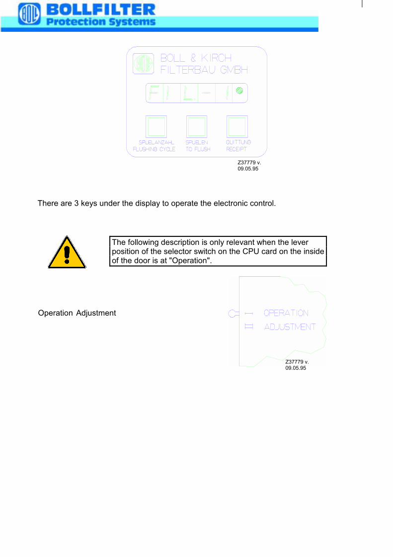
There are 3 keys under the display to operate the electronic control.
Operation Adjustment
Z37779 v.09.05.95
The following description is only relevant when the leverposition of the selector switch on the CPU card on the insideof the door is at "Operation".
Z37779 v.09.05.95
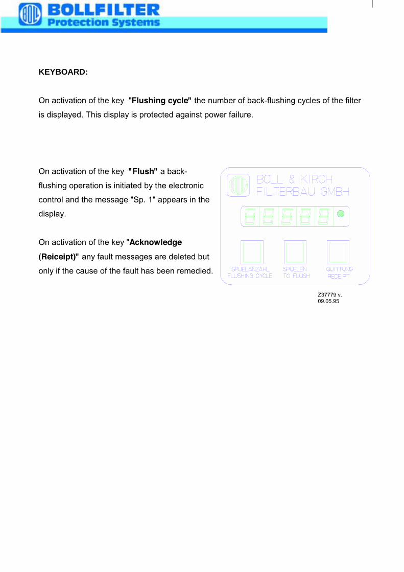
KEYBOARD:
On activation of the key "Flushing cycle" the number of back-flushing cycles of the filter
is displayed. This display is protected against power failure.
On activation of the key "Flush" a back-
flushing operation is initiated by the electronic
control and the message "Sp. 1" appears in the
display.
On activation of the key "Acknowledge(Reiceipt)" any fault messages are deleted but
only if the cause of the fault has been remedied.
Z37779 v.09.05.95
FAULT MESSAGES IN THE DISPLAY
The following faults can be shown in the display in code:
Note: In the event of any fault relating to EMC no memory contents are deleted in
controls supplied after 1 January 1998.
For type 6.61.07 (Fil.-1)Fe. 0meansovercurrent tripping or motor not wired
Fe. 1meansmax. differential pressure reached
Fe. 2meansflushing oil cartridge is saturated
For type 6.61/6.61.1 (Fil.-2)Fe. 0meansovercurrent tripping or motor not wired
Fe. 1meansmax. differential pressure reached
For type 6.60 (Fil.-4)For type 6.23/6.24/6.23.1/6.24.4 (Fil.-7)For type 6.62 (Fil.-9)Fe. 1meansmax. differential pressure reached
For type 6.14/6.17/6.18/6.19/6.44 (Fil.-6)Fe. 0meansovercurrent tripping or motor not wired
Fe. 1meansmax. differential pressure reached
For type 6.61 (Fil.-3) with alarm ΔΔΔΔp activationFor type 6.61.07 (Fil.-8) with alarm ΔΔΔΔp activationFe. 0meansovercurrent tripping or motor not wired
Fe. 1meansmax. differential pressure reached
Fe. 3meansΔp alarm "Back-flushing activation by differential pressure"
For type 6.60 (Fil.-5) with alarm ΔΔΔΔp activationFor type 6.62 (Fil.-10) with alarm ΔΔΔΔp activationFe. 1meansmax. differential pressure reached
Fe. 3meansΔp alarm "Back-flushing activation by differential pressure"
In the case of the fault messages Fe.0 (overcurrent tripping or motornot wired) and Fe. 1 (max. differential pressure reached) the potential-free alarm contacts 11, 12 and 13 are also activated as change-overcontacts at the same time.
In the case of the fault message Fe. 3 (Back-flushing activation bydifferential pressure) the potential-free alarm contacts 14, 15 and 16are activated as change-over contacts.
The fault message Fe.2 (flushing oil cartridge is saturated) is onlyshown on the display.No routing via potential-free contact.
The fault message in the display cannot be deleted by activating the"Acknowledge (Receipt)" key until the fault has been remedied.
For the reliable orientation of the software after deletion of the faultmessage, it is recommended to turn off the control with the mainswitch for about 10 seconds and then turn it on again.
If the control is not switched off with the main switch (reset function),the time-dependent back-flushing activation is no longer automaticallytriggered although the fault has been remedied.
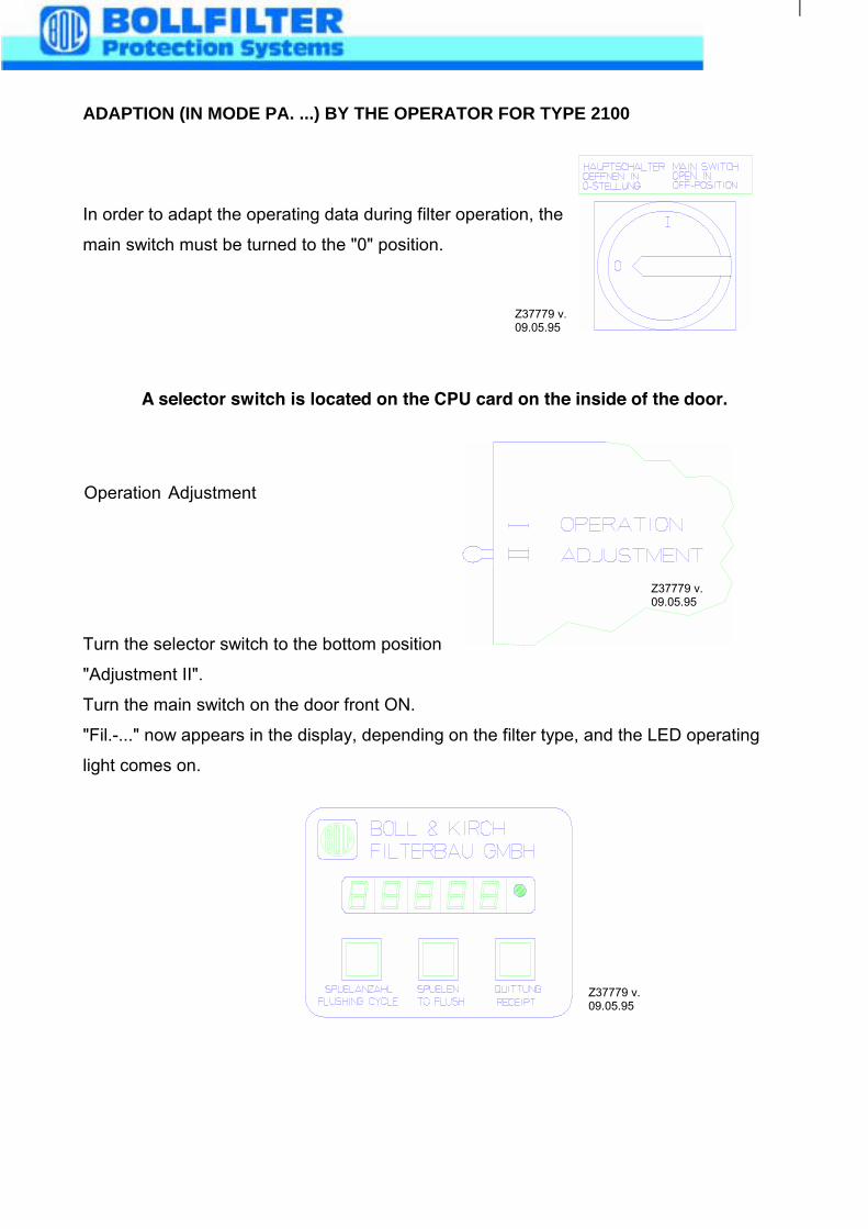
ADAPTION (IN MODE PA. ...) BY THE OPERATOR FOR TYPE 2100
In order to adapt the operating data during filter operation, the
main switch must be turned to the "0" position.
A selector switch is located on the CPU card on the inside of the door.
Operation Adjustment
Turn the selector switch to the bottom position
"Adjustment II".
Turn the main switch on the door front ON.
"Fil.-..." now appears in the display, depending on the filter type, and the LED operating
light comes on.
Z37779 v.09.05.95
Z37779 v.09.05.95
Z37779 v.09.05.95
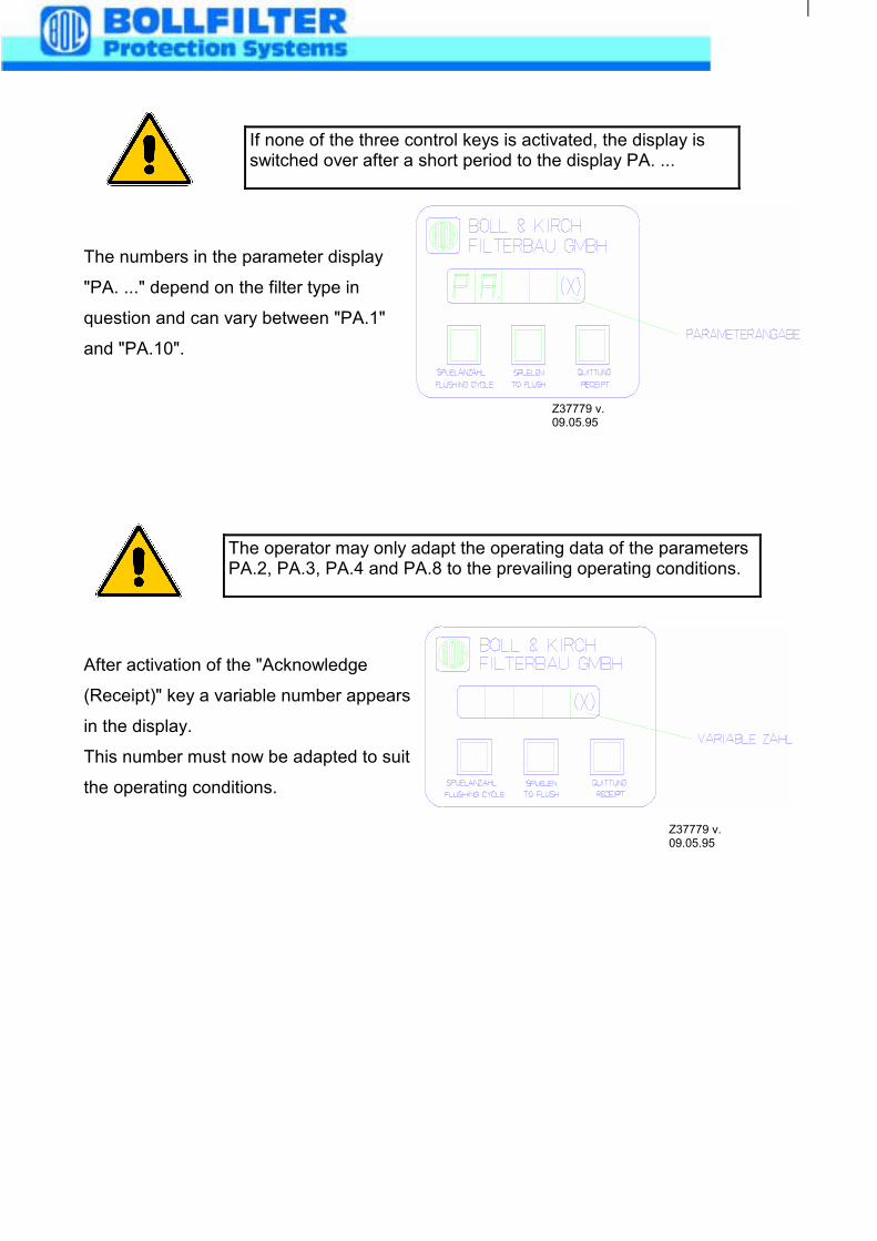
The numbers in the parameter display
"PA. ..." depend on the filter type in
question and can vary between "PA.1"
and "PA.10".
After activation of the "Acknowledge
(Receipt)" key a variable number appears
in the display.
This number must now be adapted to suit
the operating conditions.
If none of the three control keys is activated, the display isswitched over after a short period to the display PA. ...
Z37779 v.09.05.95
The operator may only adapt the operating data of the parametersPA.2, PA.3, PA.4 and PA.8 to the prevailing operating conditions.
Z37779 v.09.05.95
PA.2 Time-dependent back-flushing activation in hours from 0-59 h.
Adjustable in 1 h increments.
In all control versions
PA.3 Time-dependent back-flushing activation in minutes from 0-59 min.
Adjustable in 1 min. increments.
In all control versions
PA.4 Back-flushing time from 5 sec. to 100 sec.
Adjustable in 1 sec. increments
In all filter types apart from 6.23/6.24/6.23.1/6.24.4
PA.8 Flushing frequency monitoring
0 = Off; 1 = On
With filter type 6.60 alarm ΔΔΔΔp activation
With filter type 6.61 alarm ΔΔΔΔp activation
With filter type 6.61.07 alarm ΔΔΔΔp activation
With filter type 6.62 alarm ΔΔΔΔp activation
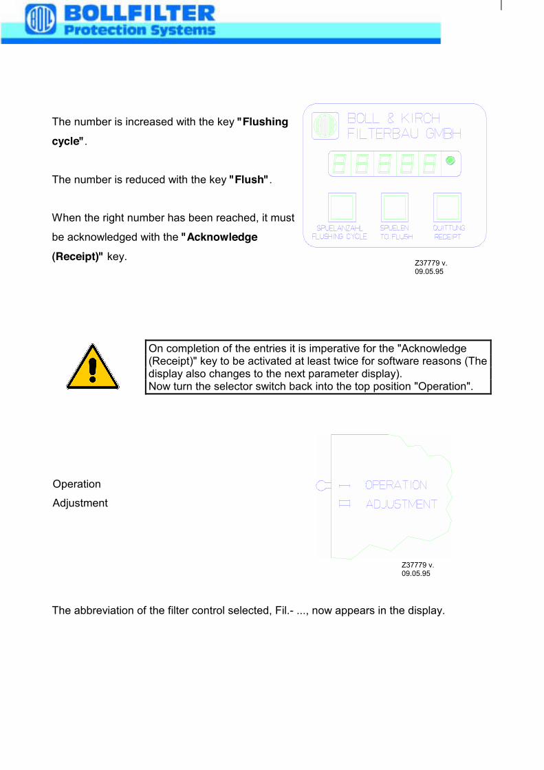
The number is increased with the key "Flushingcycle".
The number is reduced with the key "Flush".
When the right number has been reached, it must
be acknowledged with the "Acknowledge(Receipt)" key.
Operation
Adjustment
The abbreviation of the filter control selected, Fil.- ..., now appears in the display.
Z37779 v.09.05.95
On completion of the entries it is imperative for the "Acknowledge(Receipt)" key to be activated at least twice for software reasons (Thedisplay also changes to the next parameter display).Now turn the selector switch back into the top position "Operation".
Z37779 v.09.05.95
10. Servicing
Even automatic filters require inspection and servicing at regular intervals. It is to be
noted in particular that despite regular back-flushing the filter mesh can become
clogged in the course of time, depending on the quality of the medium and the by-
pass cleaning available.
Contamination on the mesh can be removed by cleaning the candle element
manually using an appropriate solvent (see Section 13). An increase in the clogging
on the mesh can be inferred from the progressively shorter intervals between back-
flushing cycles. The number of back-flushing cycles can be seen on the "Flushing
Cycle Counter" respectively display on the switch box.
To maintain trouble-free operation the following points are to be noted:
a) All connections are to be regularly checked for leaks.
b) Candle elements are to be dismantled and inspected initially after
500 flushing cycles, then after 5.000 and later every 10.000 flushing
cycles. If, however, a sharp reduction in the intervals between back-
flushing cycles should occur, inspection and cleaning should be carried
out sooner. If sudden lengthening of the intervals between back-flushing
cycles should occur all candle elements must be inspected without fail for
damage.
Before the cartridge elements are dismantled, the automatic filter
must be completely drained by automatic back-flushing (i.e. all filter
chambers). "Manual" activation on the control box. Care must be
taken to ensure that the liquid level is below the cartridge element
before the element is dismantled.
10.1 You must close the compressed air supply valve (item 127), then
starting a manual backflushing, before you are allowed to removed
the manometer (item 72). This well ensure that the compressed air
reservoir (item 13) is pressure released.
The candles are subjected to wear through reciprocal loading. It is
therefore recommended that a complete candle filter element, the
number of candle elements depending on the size of the filter, be
kept in stock.
It is expedient to renew all seals when overhauling the filter.
Check the sludge discharge for leaks every 10.000 flushing cycles.
No medium should run from the end of the sludge discharge line
during the filtration phase (except during the flushing cycle).
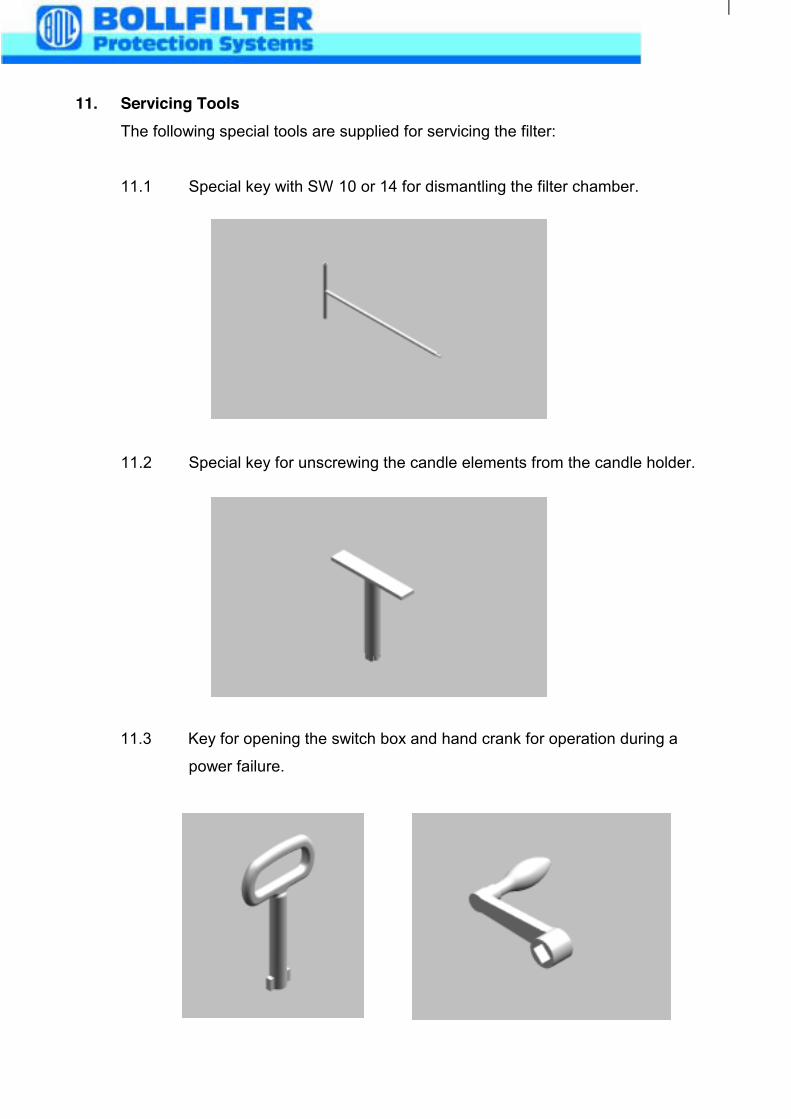
11. Servicing ToolsThe following special tools are supplied for servicing the filter:
11.1 Special key with SW 10 or 14 for dismantling the filter chamber.
11.2 Special key for unscrewing the candle elements from the candle holder.
11.3 Key for opening the switch box and hand crank for operation during a
power failure.
12. Candle Element Cleaning Agent "BOLL CLEAN 2000"
The choice of cleaning medium depends on the type of the contamination. With
fuels recipitation of paraffin and asphalt or with lubricating oils mixing of different
types of oil can form solid encrustations on the mesh. Effective cleaning of fine
meshes is achieved by soaking in "BOLL CLEAN 2000" followed by blasting with
compressed air using a cleaning gun.
PRODUCT DESCRIPTION:
BOLL CLEAN 2000 is a fluid cleaning and degreasing agent with a wide range of
application. It can be used for practically all cleaning and degreasing purposes.
BOLL CLEAN 2000 cleans rapidly, thoroughly and extremely economically.
Use of BOLL CLEAN 2000 renders safety precautions superfluous.
BOLL CLEAN 2000 has these outstanding characteristics without exhibiting the
isadvantages of solvent cleaners.
BOLL CLEAN 2000 is non-flammable
does not require special marking
does not have an irritating odour
is not caustic
is physiologically unobjectionable
is biologically degradable
is registered with the Federal Office
for the Environment, Reg.-No. 04860019
BOLL CLEAN 2000 can be undercooled or overheated during storage but remains
fully usable when returned to normal temperature.
MESH CONTAMINATED WITH HEAVY OIL:
Elements contaminated with heavy oil must be soaked in a standard commercial
solvent. After soaking the elements are cleaned in the BOLL & KIRCH Type 5.04
Cleaning Device using BOLL CLEAN 2000 and high pressure pump.
INSTRUCTIONS FOR USE:
Use of BOLL CLEAN 2000 is not restricted to a particular method of cleaning.
Depending on the operating conditions, BOLL CLEAN 2000 can be used in a dip
bath, in a spraying plant, in steam jetting or in manual application using a cloth,
brush or sponge. It can be used warm or cold.
BOLL CLEAN 2000 is miscible with water - even seawater.
Concentration for mesh cleaning: 1 : 2,5
Temperature: up to a maximum of 60 °C
The concentration depends on the type and thickness of the adhesive substance to
be removed. When used in concentration below 1 : 30 rinsing is usually not
required.
No visible film remains on the surface.
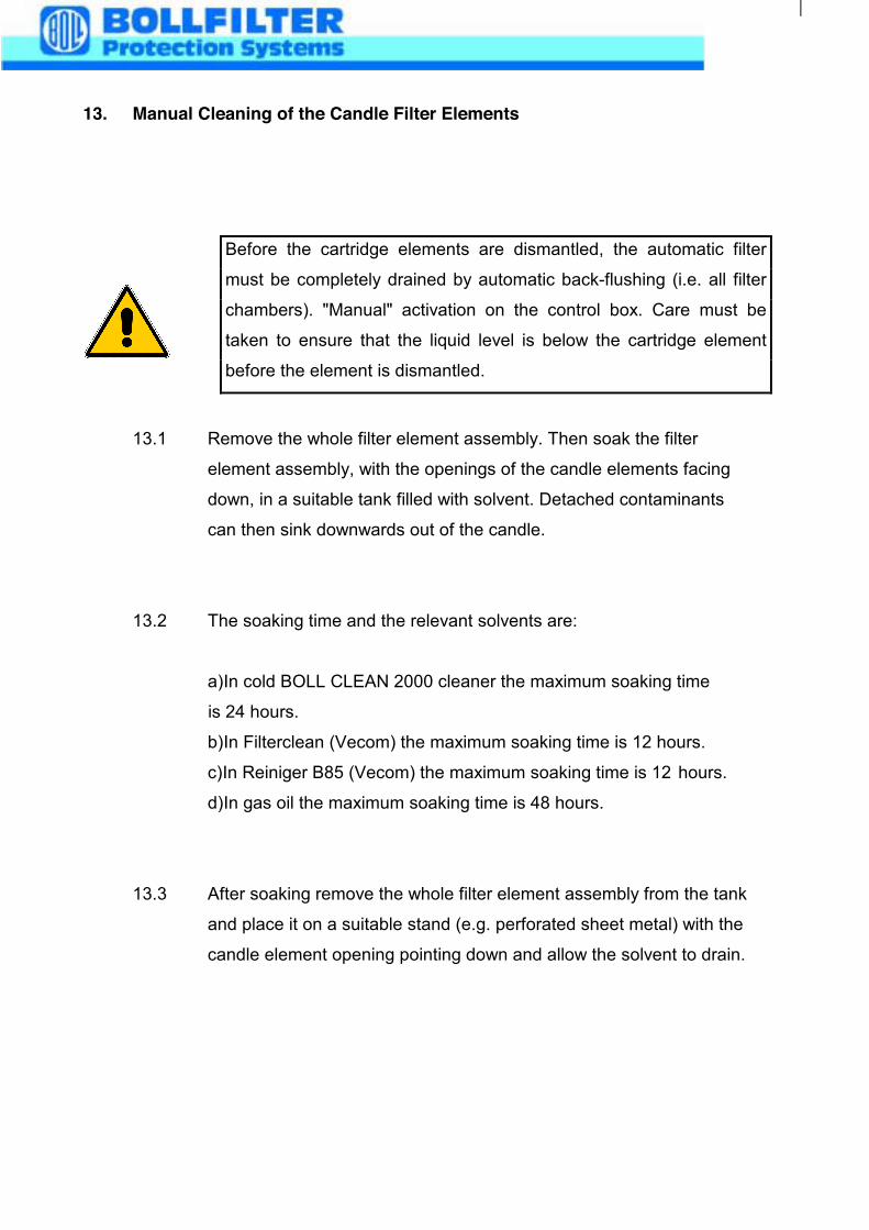
13. Manual Cleaning of the Candle Filter Elements
13.1 Remove the whole filter element assembly. Then soak the filter
element assembly, with the openings of the candle elements facing
down, in a suitable tank filled with solvent. Detached contaminants
can then sink downwards out of the candle.
13.2 The soaking time and the relevant solvents are:
a)In cold BOLL CLEAN 2000 cleaner the maximum soaking time
is 24 hours.
b)In Filterclean (Vecom) the maximum soaking time is 12 hours.
c)In Reiniger B85 (Vecom) the maximum soaking time is 12 hours.
d)In gas oil the maximum soaking time is 48 hours.
13.3 After soaking remove the whole filter element assembly from the tank
and place it on a suitable stand (e.g. perforated sheet metal) with the
candle element opening pointing down and allow the solvent to drain.
Before the cartridge elements are dismantled, the automatic filter
must be completely drained by automatic back-flushing (i.e. all filter
chambers). "Manual" activation on the control box. Care must be
taken to ensure that the liquid level is below the cartridge element
before the element is dismantled.
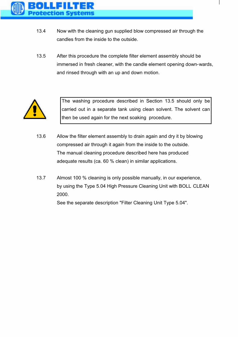
13.4 Now with the cleaning gun supplied blow compressed air through the
candles from the inside to the outside.
13.5 After this procedure the complete filter element assembly should be
immersed in fresh cleaner, with the candle element opening down-wards,
and rinsed through with an up and down motion.
13.6 Allow the filter element assembly to drain again and dry it by blowing
compressed air through it again from the inside to the outside.
The manual cleaning procedure described here has produced
adequate results (ca. 60 % clean) in similar applications.
13.7 Almost 100 % cleaning is only possible manually, in our experience,
by using the Type 5.04 High Pressure Cleaning Unit with BOLL CLEAN
2000.
See the separate description "Filter Cleaning Unit Type 5.04".
The washing procedure described in Section 13.5 should only be
carried out in a separate tank using clean solvent. The solvent can
then be used again for the next soaking procedure.
14. Manual operation of the automatic Filter
Before operating the filter manually, you have to switch off the main switch on the
control box, in the interests of safety (self turning handle will cause violations).
Attach the crank handle supplied to the free end of the motor sharft. By rotating the
motor (in either direction) the cam disc is rotated to the next changeover point (i.e.
the next filter chamber). The cam and the limit switch must align precisely.
Back flushing is initiated directly by a manual actuation of the flushing valve (with a
screw [60] driver). This manual actuation should last 12 seconds.
You have to wait 2 min. before changing over to the next filter chamber, to give time
to fill up the backflushed filter chamber.
UNTERLAGE VERS STUECKLISTE DATUM BLATTLIST-NO PARTS-LIST DATE PAGE
14312 02 07.06.02 1
ZPOS IDENTNR BENENNUNG-NENNMASS-NORM MENGE MEIDENTITY DESIGNATION-DIMENSIONS-STANDARD QUANTITY ME
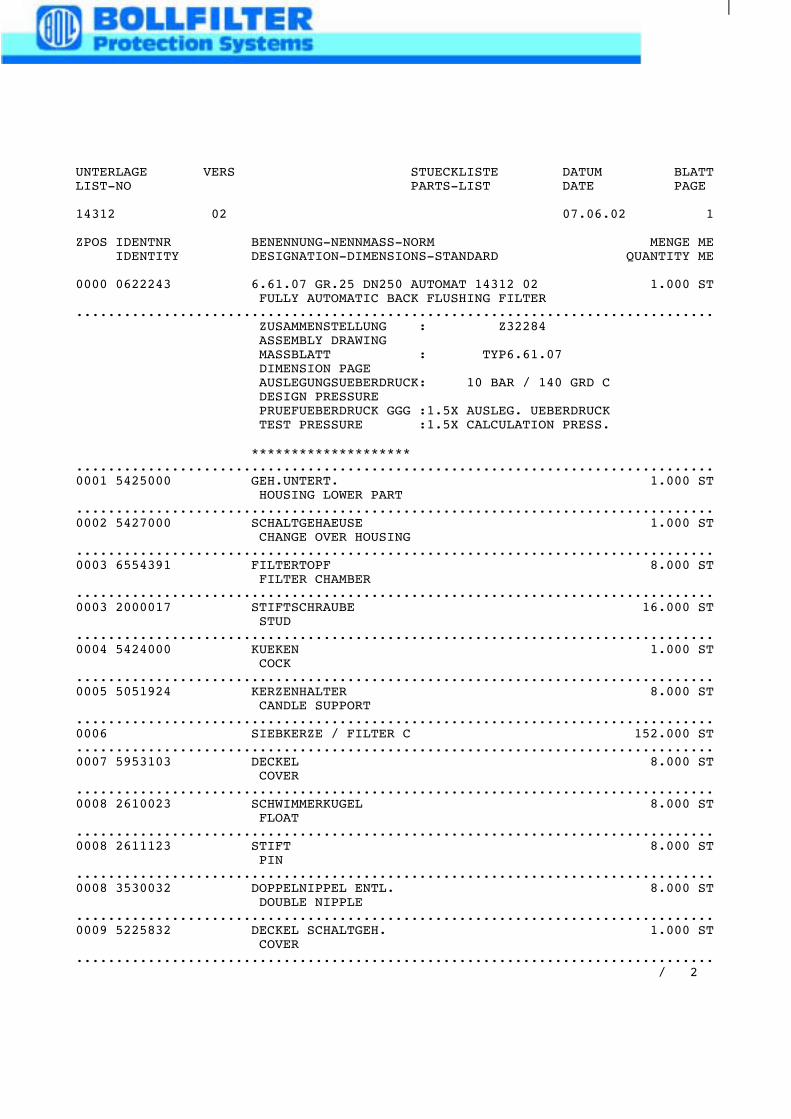
0000 0622243 6.61.07 GR.25 DN250 AUTOMAT 14312 02 1.000 STFULLY AUTOMATIC BACK FLUSHING FILTER
................................................................................ZUSAMMENSTELLUNG : Z32284ASSEMBLY DRAWINGMASSBLATT : TYP6.61.07DIMENSION PAGEAUSLEGUNGSUEBERDRUCK: 10 BAR / 140 GRD CDESIGN PRESSUREPRUEFUEBERDRUCK GGG :1.5X AUSLEG. UEBERDRUCKTEST PRESSURE :1.5X CALCULATION PRESS.
********************................................................................................0001 5425000 GEH.UNTERT. 1.000 ST
HOUSING LOWER PART................................................................................0002 5427000 SCHALTGEHAEUSE 1.000 ST
CHANGE OVER HOUSING................................................................................0003 6554391 FILTERTOPF 8.000 ST
FILTER CHAMBER................................................................................0003 2000017 STIFTSCHRAUBE 16.000 ST
STUD................................................................................0004 5424000 KUEKEN 1.000 ST
COCK................................................................................0005 5051924 KERZENHALTER 8.000 ST
CANDLE SUPPORT................................................................................0006 SIEBKERZE / FILTER C 152.000 ST................................................................................0007 5953103 DECKEL 8.000 ST
COVER................................................................................0008 2610023 SCHWIMMERKUGEL 8.000 ST
FLOAT................................................................................0008 2611123 STIFT 8.000 ST
PIN................................................................................0008 3530032 DOPPELNIPPEL ENTL. 8.000 ST
DOUBLE NIPPLE................................................................................0009 5225832 DECKEL SCHALTGEH. 1.000 ST
COVER................................................................................
/ 2
UNTERLAGE VERS STUECKLISTE DATUM BLATTLIST-NO PARTS-LIST DATE PAGE
14312 02 07.06.02 2
ZPOS IDENTNR BENENNUNG-NENNMASS-NORM MENGE MEIDENTITY DESIGNATION-DIMENSIONS-STANDARD QUANTITY ME
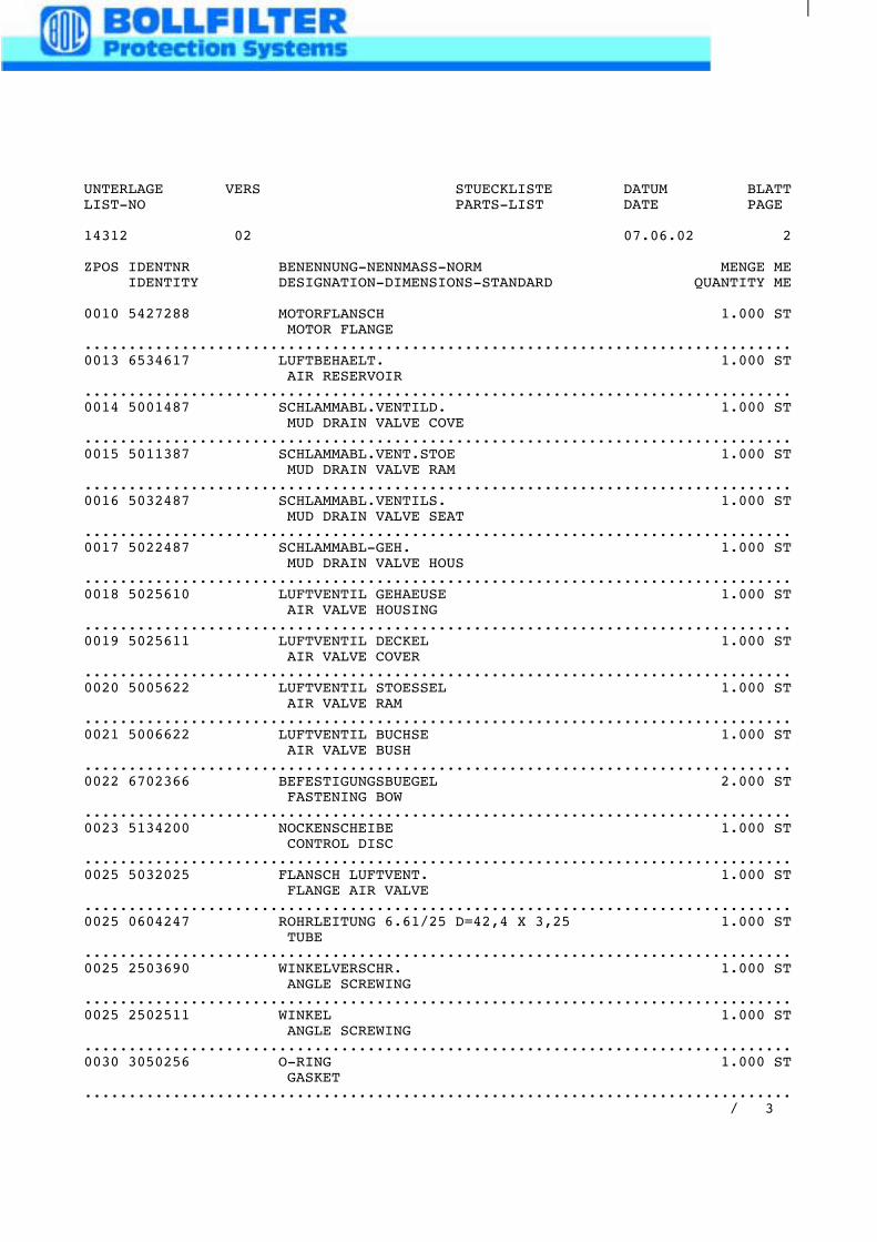
0010 5427288 MOTORFLANSCH 1.000 STMOTOR FLANGE
................................................................................0013 6534617 LUFTBEHAELT. 1.000 ST
AIR RESERVOIR................................................................................0014 5001487 SCHLAMMABL.VENTILD. 1.000 ST
MUD DRAIN VALVE COVE................................................................................0015 5011387 SCHLAMMABL.VENT.STOE 1.000 ST
MUD DRAIN VALVE RAM................................................................................0016 5032487 SCHLAMMABL.VENTILS. 1.000 ST
MUD DRAIN VALVE SEAT................................................................................0017 5022487 SCHLAMMABL-GEH. 1.000 ST
MUD DRAIN VALVE HOUS................................................................................0018 5025610 LUFTVENTIL GEHAEUSE 1.000 ST
AIR VALVE HOUSING................................................................................0019 5025611 LUFTVENTIL DECKEL 1.000 ST
AIR VALVE COVER................................................................................0020 5005622 LUFTVENTIL STOESSEL 1.000 ST
AIR VALVE RAM................................................................................0021 5006622 LUFTVENTIL BUCHSE 1.000 ST
AIR VALVE BUSH................................................................................0022 6702366 BEFESTIGUNGSBUEGEL 2.000 ST
FASTENING BOW................................................................................0023 5134200 NOCKENSCHEIBE 1.000 ST
CONTROL DISC................................................................................0025 5032025 FLANSCH LUFTVENT. 1.000 ST
FLANGE AIR VALVE................................................................................0025 0604247 ROHRLEITUNG 6.61/25 D=42,4 X 3,25 1.000 ST
TUBE................................................................................0025 2503690 WINKELVERSCHR. 1.000 ST
ANGLE SCREWING................................................................................0025 2502511 WINKEL 1.000 ST
ANGLE SCREWING................................................................................0030 3050256 O-RING 1.000 ST
GASKET................................................................................
/ 3
UNTERLAGE VERS STUECKLISTE DATUM BLATTLIST-NO PARTS-LIST DATE PAGE
14312 02 07.06.02 3
ZPOS IDENTNR BENENNUNG-NENNMASS-NORM MENGE MEIDENTITY DESIGNATION-DIMENSIONS-STANDARD QUANTITY ME
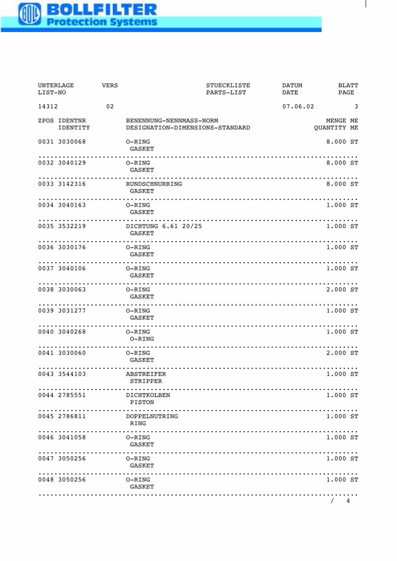
0031 3030068 O-RING 8.000 STGASKET
................................................................................0032 3040129 O-RING 8.000 ST
GASKET................................................................................0033 3142316 RUNDSCHNURRING 8.000 ST
GASKET................................................................................0034 3040163 O-RING 1.000 ST
GASKET................................................................................0035 3532219 DICHTUNG 6.61 20/25 1.000 ST
GASKET................................................................................0036 3030176 O-RING 1.000 ST
GASKET................................................................................0037 3040106 O-RING 1.000 ST
GASKET................................................................................0038 3030063 O-RING 2.000 ST
GASKET................................................................................0039 3031277 O-RING 1.000 ST
GASKET................................................................................0040 3040268 O-RING 1.000 ST
O-RING................................................................................0041 3030060 O-RING 2.000 ST
GASKET................................................................................0043 3544103 ABSTREIFER 1.000 ST
STRIPPER................................................................................0044 2785551 DICHTKOLBEN 1.000 ST
PISTON................................................................................0045 2786811 DOPPELNUTRING 1.000 ST
RING................................................................................0046 3041058 O-RING 1.000 ST
GASKET................................................................................0047 3050256 O-RING 1.000 ST
GASKET................................................................................0048 3050256 O-RING 1.000 ST
GASKET................................................................................
/ 4
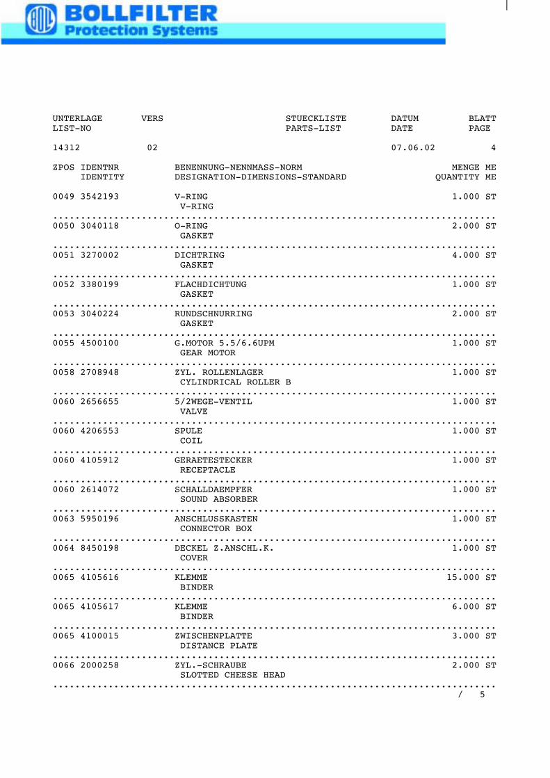
UNTERLAGE VERS STUECKLISTE DATUM BLATTLIST-NO PARTS-LIST DATE PAGE
14312 02 07.06.02 4
ZPOS IDENTNR BENENNUNG-NENNMASS-NORM MENGE MEIDENTITY DESIGNATION-DIMENSIONS-STANDARD QUANTITY ME
0049 3542193 V-RING 1.000 STV-RING
................................................................................0050 3040118 O-RING 2.000 ST
GASKET................................................................................0051 3270002 DICHTRING 4.000 ST
GASKET................................................................................0052 3380199 FLACHDICHTUNG 1.000 ST
GASKET................................................................................0053 3040224 RUNDSCHNURRING 2.000 ST
GASKET................................................................................0055 4500100 G.MOTOR 5.5/6.6UPM 1.000 ST
GEAR MOTOR................................................................................0058 2708948 ZYL. ROLLENLAGER 1.000 ST
CYLINDRICAL ROLLER B................................................................................0060 2656655 5/2WEGE-VENTIL 1.000 ST
VALVE................................................................................0060 4206553 SPULE 1.000 ST
COIL................................................................................0060 4105912 GERAETESTECKER 1.000 ST
RECEPTACLE................................................................................0060 2614072 SCHALLDAEMPFER 1.000 ST
SOUND ABSORBER................................................................................0063 5950196 ANSCHLUSSKASTEN 1.000 ST
CONNECTOR BOX................................................................................0064 8450198 DECKEL Z.ANSCHL.K. 1.000 ST
COVER................................................................................0065 4105616 KLEMME 15.000 ST
BINDER................................................................................0065 4105617 KLEMME 6.000 ST
BINDER................................................................................0065 4100015 ZWISCHENPLATTE 3.000 ST
DISTANCE PLATE................................................................................0066 2000258 ZYL.-SCHRAUBE 2.000 ST
SLOTTED CHEESE HEAD................................................................................
/ 5
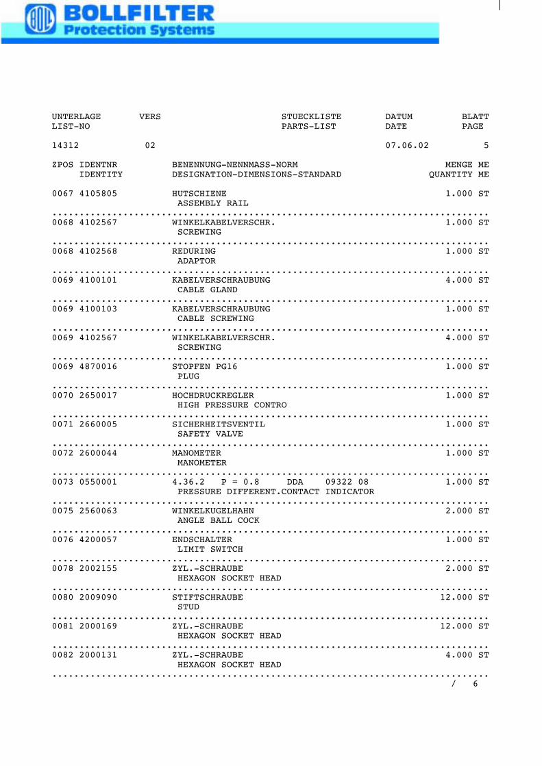
UNTERLAGE VERS STUECKLISTE DATUM BLATTLIST-NO PARTS-LIST DATE PAGE
14312 02 07.06.02 5
ZPOS IDENTNR BENENNUNG-NENNMASS-NORM MENGE MEIDENTITY DESIGNATION-DIMENSIONS-STANDARD QUANTITY ME
0067 4105805 HUTSCHIENE 1.000 STASSEMBLY RAIL
................................................................................0068 4102567 WINKELKABELVERSCHR. 1.000 ST
SCREWING................................................................................0068 4102568 REDURING 1.000 ST
ADAPTOR................................................................................0069 4100101 KABELVERSCHRAUBUNG 4.000 ST
CABLE GLAND................................................................................0069 4100103 KABELVERSCHRAUBUNG 1.000 ST
CABLE SCREWING................................................................................0069 4102567 WINKELKABELVERSCHR. 4.000 ST
SCREWING................................................................................0069 4870016 STOPFEN PG16 1.000 ST
PLUG................................................................................0070 2650017 HOCHDRUCKREGLER 1.000 ST
HIGH PRESSURE CONTRO................................................................................0071 2660005 SICHERHEITSVENTIL 1.000 ST
SAFETY VALVE................................................................................0072 2600044 MANOMETER 1.000 ST
MANOMETER................................................................................0073 0550001 4.36.2 P = 0.8 DDA 09322 08 1.000 ST
PRESSURE DIFFERENT.CONTACT INDICATOR................................................................................0075 2560063 WINKELKUGELHAHN 2.000 ST
ANGLE BALL COCK................................................................................0076 4200057 ENDSCHALTER 1.000 ST
LIMIT SWITCH................................................................................0078 2002155 ZYL.-SCHRAUBE 2.000 ST
HEXAGON SOCKET HEAD................................................................................0080 2009090 STIFTSCHRAUBE 12.000 ST
STUD................................................................................0081 2000169 ZYL.-SCHRAUBE 12.000 ST
HEXAGON SOCKET HEAD................................................................................0082 2000131 ZYL.-SCHRAUBE 4.000 ST
HEXAGON SOCKET HEAD................................................................................
/ 6
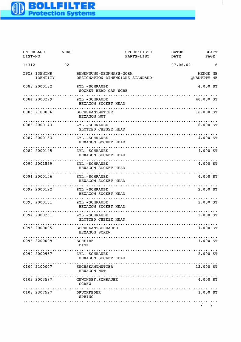
UNTERLAGE VERS STUECKLISTE DATUM BLATTLIST-NO PARTS-LIST DATE PAGE
14312 02 07.06.02 6
ZPOS IDENTNR BENENNUNG-NENNMASS-NORM MENGE MEIDENTITY DESIGNATION-DIMENSIONS-STANDARD QUANTITY ME
0083 2000132 ZYL.-SCHRAUBE 4.000 STSOCKET HEAD CAP SCRE
................................................................................0084 2000279 ZYL.-SCHRAUBE 40.000 ST
HEXAGON SOCKET HEAD................................................................................0085 2100006 SECHSKANTMUTTER 16.000 ST
HEXAGON NUT................................................................................0086 2000143 ZYL.-SCHRAUBE 6.000 ST
SLOTTED CHESSE HEAD................................................................................0087 2000153 ZYL.-SCHRAUBE 4.000 ST
HEXAGON SOCKET HEAD................................................................................0089 2000145 ZYL.-SCHRAUBE 4.000 ST
HEXAGON SOCKET HEAD................................................................................0090 2001539 ZYL.-SCHRAUBE 4.000 ST
HEXAGON SOCKET HEAD................................................................................0091 2000156 ZYL.-SCHRAUBE 4.000 ST
HEXAGON SOCKET HEAD................................................................................0092 2000122 ZYL.-SCHRAUBE 2.000 ST
HEXAGON SOCKET HEAD................................................................................0093 2000131 ZYL.-SCHRAUBE 2.000 ST
HEXAGON SOCKET HEAD................................................................................0094 2000261 ZYL.-SCHRAUBE 2.000 ST
SLOTTED CHEESE HEAD................................................................................0095 2000095 SECHSKANTSCHRAUBE 1.000 ST
HEXAGON SCREW................................................................................0096 2200009 SCHEIBE 1.000 ST
DISK................................................................................0099 2000967 ZYL.-SCHRAUBE 2.000 ST
HEXAGON SOCKET HEAD................................................................................0100 2100007 SECHSKANTMUTTER 12.000 ST
HEXAGON NUT................................................................................0102 2003587 GEWINDEF.SCHRAUBE 4.000 ST
SCREW................................................................................0103 2307527 DRUCKFEDER 1.000 ST
SPRING................................................................................
/ 7
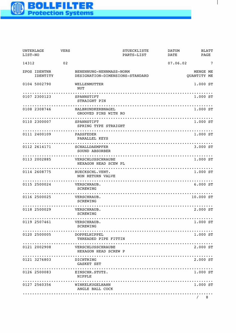
UNTERLAGE VERS STUECKLISTE DATUM BLATTLIST-NO PARTS-LIST DATE PAGE
14312 02 07.06.02 7
ZPOS IDENTNR BENENNUNG-NENNMASS-NORM MENGE MEIDENTITY DESIGNATION-DIMENSIONS-STANDARD QUANTITY ME
0104 5002790 WELLENMUTTER 1.000 STNUT
................................................................................0107 2300123 SPANNSTIFT 1.000 ST
STRAIGHT PIN................................................................................0108 2308746 HALBRUNDKERBNAGEL 1.000 ST
GROOVED PINS WITH RO................................................................................0110 2300007 SPANNSTIFT 1.000 ST
SPRING TYPE STRAIGHT................................................................................0111 2400109 PASSFEDER 1.000 ST
PARALLEL KEYS................................................................................0112 2614171 SCHALLDAEMPFER 3.000 ST
SOUND ABSORBER................................................................................0113 2002885 VERSCHLUSSCHRAUBE 1.000 ST
HEXAGON HEAD SCEW PL................................................................................0114 2608775 RUECKSCHL.VENT. 1.000 ST
NON RETURN VALVE................................................................................0115 2500024 VERSCHRAUB. 6.000 ST
SCREWING................................................................................0116 2500025 VERSCHRAUB. 10.000 ST
SCREWING................................................................................0118 2500029 VERSCHRAUB. 2.000 ST
SCREWING................................................................................0119 2507461 VERSCHRAUB. 1.000 ST
SCREWING................................................................................0120 2500005 DOPPELNIPPEL 1.000 ST
THREADED PIPE FITTIN................................................................................0121 2002908 VERSCHLUSSCHRAUBE 2.000 ST
HEXAGON HEAD SCREW P................................................................................0121 3276803 DICHTRING 2.000 ST
GASKET SET................................................................................0126 2500083 EINSCHR.STUTZ. 1.000 ST
NIPPLE................................................................................0127 2560356 WINKELKUGELHAHN 1.000 ST
ANGLE BALL COCK................................................................................
/ 8
UNTERLAGE VERS STUECKLISTE DATUM BLATTLIST-NO PARTS-LIST DATE PAGE
14312 02 07.06.02 8
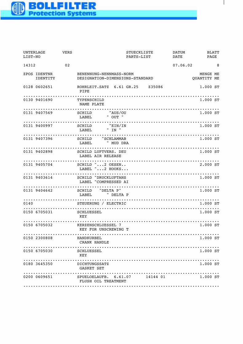
ZPOS IDENTNR BENENNUNG-NENNMASS-NORM MENGE MEIDENTITY DESIGNATION-DIMENSIONS-STANDARD QUANTITY ME
0128 0602651 ROHRLEIT.SATZ 6.61 GR.25 Z35086 1.000 STPIPE
................................................................................0130 9401690 TYPENSCHILD 1.000 ST
NAME PLATE................................................................................0131 9407569 SCHILD "AUS/OU 1.000 ST
LABEL " OUT "................................................................................0131 9400997 SCHILD "EIN/IN 1.000 ST
LABEL " IN "................................................................................0131 9407396 SCHILD "SCHLAMMAB 1.000 ST
LABEL " MUD DRA................................................................................0131 9402898 SCHILD LUFTVERS. DEU 1.000 ST
LABEL AIR RELEASE................................................................................0131 9405704 SCHILD "...2 OESEN.. 2.000 ST
LABEL "...2 HOOKS...................................................................................0131 9403614 SCHILD "DRUCKLUFTANS 1.000 ST
LABEL "COMPRESSED AI................................................................................0131 9404642 SCHILD "DELTA P" 1.000 ST
LABEL " DELTA P................................................................................0140 STEUERUNG / ELECTRIC 1.000 ST................................................................................0150 6705031 SCHLUESSEL 1.000 ST
KEY................................................................................0150 6705032 KERZENSCHLUESSEL 7 1.000 ST
KEY FOR UNSCREWING T................................................................................0150 2300808 HANDKURBEL 1.000 ST
CRANK HANDLE................................................................................0150 6705030 SCHLUESSEL 1.000 ST
KEY................................................................................0180 3645350 DICHTUNGSSATZ 1.000 ST
GASKET SET................................................................................0200 0609651 SPUELOELAUFB. 6.61.07 14144 01 1.000 ST
FLUSH OIL TREATMENT................................................................................
UNTERLAGE VERS STUECKLISTE DATUM BLATTLIST-NO PARTS-LIST DATE PAGE
14144 00 07.06.02 1
ZPOS IDENTNR BENENNUNG-NENNMASS-NORM MENGE MEIDENTITY DESIGNATION-DIMENSIONS-STANDARD QUANTITY ME
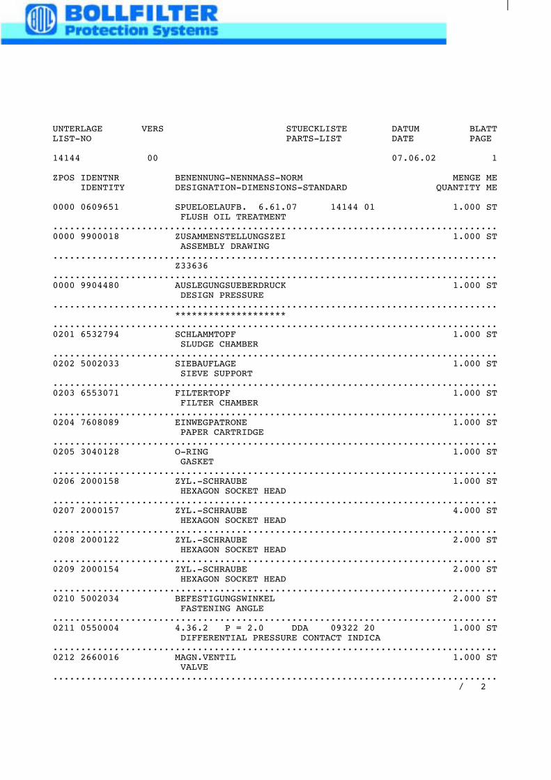
0000 0609651 SPUELOELAUFB. 6.61.07 14144 01 1.000 STFLUSH OIL TREATMENT
................................................................................0000 9900018 ZUSAMMENSTELLUNGSZEI 1.000 ST
ASSEMBLY DRAWING................................................................................
Z33636................................................................................0000 9904480 AUSLEGUNGSUEBERDRUCK 1.000 ST
DESIGN PRESSURE................................................................................
********************................................................................................0201 6532794 SCHLAMMTOPF 1.000 ST
SLUDGE CHAMBER................................................................................0202 5002033 SIEBAUFLAGE 1.000 ST
SIEVE SUPPORT................................................................................0203 6553071 FILTERTOPF 1.000 ST
FILTER CHAMBER................................................................................0204 7608089 EINWEGPATRONE 1.000 ST
PAPER CARTRIDGE................................................................................0205 3040128 O-RING 1.000 ST
GASKET................................................................................0206 2000158 ZYL.-SCHRAUBE 1.000 ST
HEXAGON SOCKET HEAD................................................................................0207 2000157 ZYL.-SCHRAUBE 4.000 ST
HEXAGON SOCKET HEAD................................................................................0208 2000122 ZYL.-SCHRAUBE 2.000 ST
HEXAGON SOCKET HEAD................................................................................0209 2000154 ZYL.-SCHRAUBE 2.000 ST
HEXAGON SOCKET HEAD................................................................................0210 5002034 BEFESTIGUNGSWINKEL 2.000 ST
FASTENING ANGLE................................................................................0211 0550004 4.36.2 P = 2.0 DDA 09322 20 1.000 ST
DIFFERENTIAL PRESSURE CONTACT INDICA................................................................................0212 2660016 MAGN.VENTIL 1.000 ST
VALVE................................................................................
/ 2
UNTERLAGE VERS STUECKLISTE DATUM BLATTLIST-NO PARTS-LIST DATE PAGE
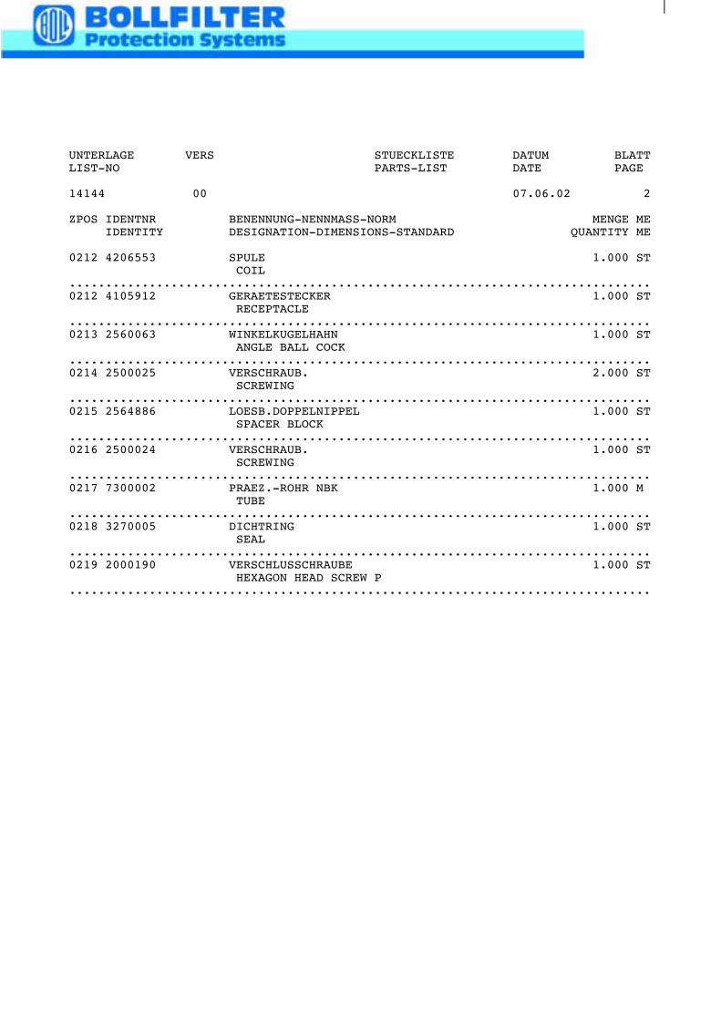
14144 00 07.06.02 2
ZPOS IDENTNR BENENNUNG-NENNMASS-NORM MENGE MEIDENTITY DESIGNATION-DIMENSIONS-STANDARD QUANTITY ME
0212 4206553 SPULE 1.000 STCOIL
................................................................................0212 4105912 GERAETESTECKER 1.000 ST
RECEPTACLE................................................................................0213 2560063 WINKELKUGELHAHN 1.000 ST
ANGLE BALL COCK................................................................................0214 2500025 VERSCHRAUB. 2.000 ST
SCREWING................................................................................0215 2564886 LOESB.DOPPELNIPPEL 1.000 ST
SPACER BLOCK................................................................................0216 2500024 VERSCHRAUB. 1.000 ST
SCREWING................................................................................0217 7300002 PRAEZ.-ROHR NBK 1.000 M
TUBE................................................................................0218 3270005 DICHTRING 1.000 ST
SEAL................................................................................0219 2000190 VERSCHLUSSCHRAUBE 1.000 ST
HEXAGON HEAD SCREW P................................................................................
01.01.00TYP4.36.2
PG13.5
G1/4
G1/
4
- +
1
2
1a
3a 3
P1 P2
CIRCUIT DIAGRAM
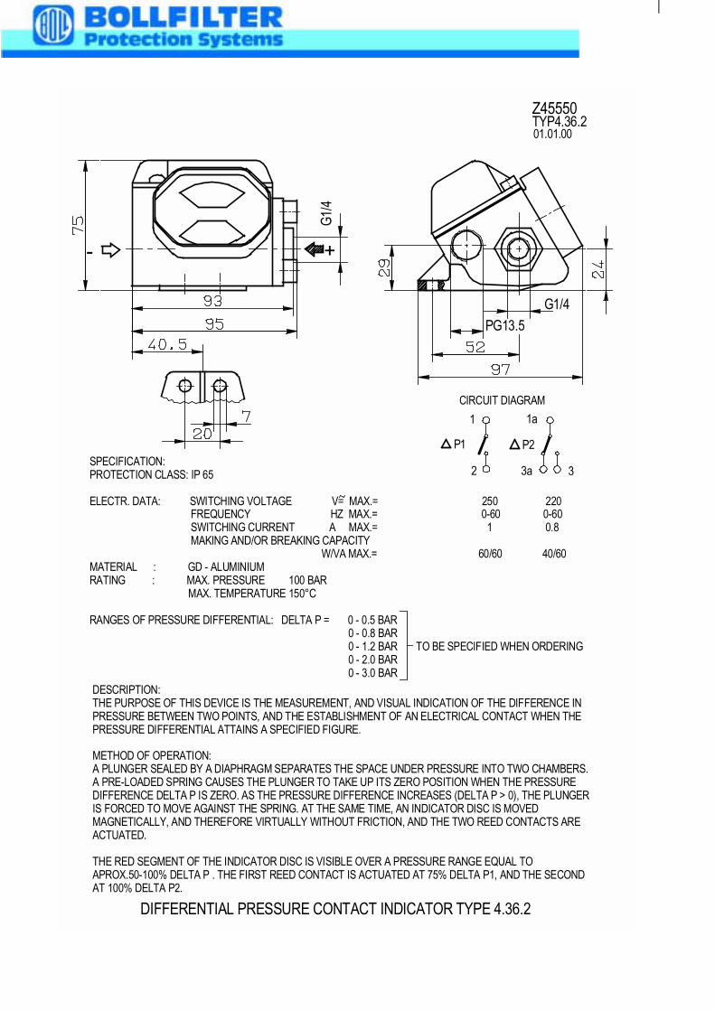
DIFFERENTIAL PRESSURE CONTACT INDICATOR TYPE 4.36.2
DESCRIPTION:THE PURPOSE OF THIS DEVICE IS THE MEASUREMENT, AND VISUAL INDICATION OF THE DIFFERENCE INPRESSURE BETWEEN TWO POINTS, AND THE ESTABLISHMENT OF AN ELECTRICAL CONTACT WHEN THEPRESSURE DIFFERENTIAL ATTAINS A SPECIFIED FIGURE.
METHOD OF OPERATION:A PLUNGER SEALED BY A DIAPHRAGM SEPARATES THE SPACE UNDER PRESSURE INTO TWO CHAMBERS.A PRE-LOADED SPRING CAUSES THE PLUNGER TO TAKE UP ITS ZERO POSITION WHEN THE PRESSUREDIFFERENCE DELTA P IS ZERO. AS THE PRESSURE DIFFERENCE INCREASES (DELTA P > 0), THE PLUNGERIS FORCED TO MOVE AGAINST THE SPRING. AT THE SAME TIME, AN INDICATOR DISC IS MOVEDMAGNETICALLY, AND THEREFORE VIRTUALLY WITHOUT FRICTION, AND THE TWO REED CONTACTS AREACTUATED.
THE RED SEGMENT OF THE INDICATOR DISC IS VISIBLE OVER A PRESSURE RANGE EQUAL TOAPROX.50-100% DELTA P . THE FIRST REED CONTACT IS ACTUATED AT 75% DELTA P1, AND THE SECONDAT 100% DELTA P2.
SPECIFICATION:PROTECTION CLASS: IP 65
ELECTR. DATA: SWITCHING VOLTAGE V= MAX.= 250 220 FREQUENCY HZ MAX.= 0-60 0-60 SWITCHING CURRENT A MAX.= 1 0.8 MAKING AND/OR BREAKING CAPACITY W/VA MAX.= 60/60 40/60MATERIAL : GD - ALUMINIUMRATING : MAX. PRESSURE 100 BAR MAX. TEMPERATURE 150°C
RANGES OF PRESSURE DIFFERENTIAL: DELTA P = 0 - 0.5 BAR 0 - 0.8 BAR 0 - 1.2 BAR TO BE SPECIFIED WHEN ORDERING 0 - 2.0 BAR 0 - 3.0 BAR
Z45550
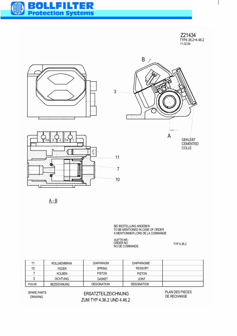
POS.NR. BEZEICHNUNG DESIGNATION DESIGNATION
37
1011 ROLLMEMBRAN DIAPHRAGM DIAPHRAGME
FEDER
KOLBEN
DICHTUNG GASKET JOINT
PISTON PISTON
SPRING RESSORT
ERSATZTEILZEICHNUNGZUM TYP 4.36.2 UND 4.46.2
SPARE PARTS PLAN DES PIECES
11.02.94
Z21434
DRAWING DE RECHANGE
3
7
11
GEKLEBT11a233aA
B
A - B
10
TYP 4.36.2
TYP4.36.2+4.46.2
TO BE MENTIONED IN CASE OF ORDER
ORDER NO.
BEI BESTELLUNG ANGEBEN
AUFTR.NR.:
CEMENTEDCOLLE
A MENTIONNER LORS DE LA COMMANDE
NO DE COMMANDE


