Embed Size (px)
Citation preview
CHAPTER THREE
Boiling Liquid Expanding VaporExplosions (BLEVEs)
3.1 DEFINITIONS AND CHARACTERISTICS OF BLEVEs
This chapter is essentially identical to the paper by Eckhoff (2014). Ac-cording to the extensive review by Abbasi and Abbasi (2007), the BoilingLiquid Expanding Vapor Explosion (BLEVE) was probably adopted forthe first time in 1957 by researchers at Factory Mutual at Factory MutualResearch Corp., United States. They had analyzed the failure of a vesselthat contained an overheated mixture of formalin and phenol and suggestedthat the container suffered a BLEVE. Later, Walls (1978, 1979) defined aBLEVE as “a failure of a major liquid-filled container into two or morepieces at a moment when the temperature of the contained liquid is wellabove its boiling point at normal atmospheric pressure.”
Birk and Cunningham (1994) defined a BLEVE as “the explosive releaseof expanding vapour and boiling liquid when a container holding apressure-liquefied gas fails catastrophically.” Catastrophic failure was definedas “the sudden opening of a tank/container to release its contents nearlyinstantaneously.”
The definition of a BLEVE presented by CCPS (1999) (Center forChemical Process Safety) is “a sudden release of a large mass of pressurizedsuperheated liquid to the atmosphere.” The sudden release is due to a sud-den containment failure caused by fire, a missile, corrosion, a manufacturingdefect, internal overheating etc.
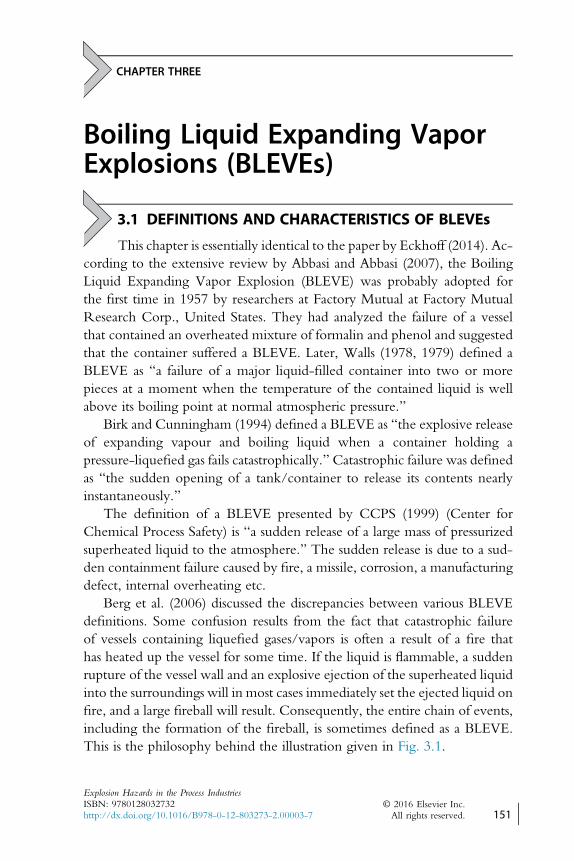
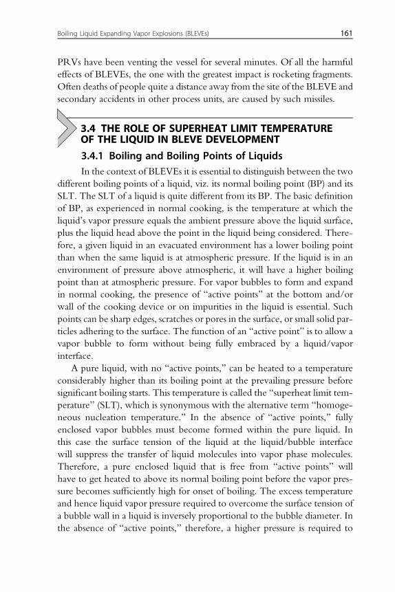
Berg et al. (2006) discussed the discrepancies between various BLEVEdefinitions. Some confusion results from the fact that catastrophic failureof vessels containing liquefied gases/vapors is often a result of a fire thathas heated up the vessel for some time. If the liquid is flammable, a suddenrupture of the vessel wall and an explosive ejection of the superheated liquidinto the surroundings will in most cases immediately set the ejected liquid onfire, and a large fireball will result. Consequently, the entire chain of events,including the formation of the fireball, is sometimes defined as a BLEVE.This is the philosophy behind the illustration given in Fig. 3.1.
Explosion Hazards in the Process IndustriesISBN: 9780128032732http://dx.doi.org/10.1016/B978-0-12-803273-2.00003-7
© 2016 Elsevier Inc.All rights reserved. 151 j
Berg et al., however, suggest that the definition of a BLEVE should notinclude a possible subsequent generation of a fireball, but comprise only theexplosive rupture of the pressure vessel and the subsequent flash evaporationof its superheated liquid content. Some definitions of BLEVEs require thatthe liquid initially confined in the vessel has to be heated above its superheatlimit temperature (SLT) at atmospheric pressure (see Section 3.4.2 in thefollowing) before vessel rupture takes place. Other, less strict, definitionsonly require that the liquid temperature at vessel rupture significantly ex-ceeds the liquid boiling point at atmospheric pressure. In any case, the higherthe temperature of the liquid is at the moment of tank rupture, the moresevere will be the accident.
3.2 CHAIN OF EVENTS LEADING TO BLEVEs ANDTHEIR CONSEQUENCES
The following summary to a significant extent follows the same mainlines as in the very extensive review by Abbasi and Abbasi (2007).
Figure 3.1 Illustration of a BLEVE, including the major secondary fireball following igni-tion of the ejected vapor/liquid.From Marshall, V.C., 1987. Major Chemical Hazards, Elis Horwood Series in ChemicalEngineering. Ellis Horwood Ltd/Halsted Press, A Division of John Wiley & Sons, Chichester/New York, ISBN:0-470-20813-9.
152 Explosion Hazards in the Process Industries
3.2.1 A Vessel Containing Pressurized Liquefied Gas IsAccidentally Exposed to Heat (Fire)
A pressure vessel can fail even at normal ambient temperature by missileimpact, fatigue, corrosion, or an accidental excessive rise of the process pres-sure. However, in the present context the main focus will be on excessivepressurization due to accidental heating of the vessel from the outside. Itis then important to keep in mind that a pressure vessel is designed to with-stand the relief valve set pressure only at the design temperature conditions,which may be just ambient atmospheric temperature.
Pressurized liquefied gas (PLG) is a substance that is in the gaseous state atnormal ambient temperature and pressure, but which has been liquefied bycompression and is kept as a liquid at normal ambient temperature in a pres-sure vessel. Propane and butane are common examples. In the case of acci-dental heating of a vessel containing PLG, eg, by the heat from a fire, asillustrated in Fig. 3.1, the already elevated vapor pressure inside the vesselwill rise further. When the pressure reaches the set pressure of the pressurerelief valve of the vessel, vapor from the liquid in the vessel is expelled intothe open atmosphere, and the liquid level in the vessel will drop as furtherliquid continues to evaporate. As long as most of the vessel volume is occu-pied by the liquid, most of the vessel wall will be effectively cooled by theliquid. However, as the liquid continues to evaporate and escape via thepressure relief valve, the proportion of the vessel wall that is effectivelycooled decreases. Eventually the portion of the vessel wall that is not in con-tact with the liquid weakens due to the temperature rise caused by theexternal fire load, and may fail. Schulz-Forberg et al. (1984) investigatedthe failure mechanisms of propane storage tanks exposed to thermal stress,including fires.
3.2.2 Sudden Depressurization and Evaporation of theHot Liquid
When the vessel fails, the liquid pressure suddenly drops to atmosphericpressure. Because the liquid temperature is well above the atmospheric pres-sure boiling point, the liquid will evaporate abruptly and violently andexpand to a cloud of a volume between several hundred and 2000 timesthat of the original liquid volume. If the liquid temperature is significantlyhigher than its SLT (see Section 3.4 in the following) at atmospheric pres-sure, most of the liquid volume can undergo extremely fast and homoge-neous nucleation and evaporation. In that case, the vaporization/expansion process will be extremely fast and violent, and typically occur
Boiling Liquid Expanding Vapor Explosions (BLEVEs) 153
within 1 ms after the abrupt vessel depressurization caused by the suddenvessel failure.
The nucleation and vaporization processes require heat, which is takenfrom the liquid itself. Therefore, the liquid temperature will drop as thevolumetric evaporation progresses. As soon as the liquid temperature dropsbelow the SLT, the very rapid volumetric nucleation and vaporization ter-minates and normal boiling at the hot surfaces becomes the dominating pro-cess of vapor production. Hence, the more the liquid temperature at vesselfailure exceeds the SLT of the liquid, the greater will be the fraction of theliquid that can flash almost instantaneously to vapor.
It is important to emphasize that a BLEVE can occur even when thetemperature of the suddenly depressurized liquid is below the SLT of theliquid at atmospheric pressure, but still significantly higher than the atmo-spheric boiling point. However, clearly the intensity of the evaporationwill then be lower than if the initial liquid temperature exceeds the SLTat atmospheric pressure.
3.2.3 Blast Wave Emission From BLEVEsBerg et al. (2006) discussed various models for calculating the strength ofblast waves emitted from BLEVEs.
Acoustic modeling of blast wave emission requires full knowledge of thesource overpressure as a function of time. This, in turn, requires full knowl-edge of the physical characteristics of the liquid release as a function of time,from the onset of the crack development in the pressurized vessel. Crackdevelopment is a complex process that depends strongly on the designand structure of the actual vessel. Therefore, simplifying assumptions arerequired. One such assumption is that the liquid release rate grows linearlywith time. Using this assumption, Berg et al. considered as an example aBLEVE from a 50 m3 propane tank in the open. They then calculatedthe maximum overpressure at a distance 10 m away from the tank, as afunction of total release time Dt. With Dt equal to 0.05, 0.2, and 1.0 s,respectively, the corresponding maximum overpressures Dp were 1.06,0.07, and 0.0003 bar.
Gas dynamic modeling gives results that are more accurate provided suffi-cient input information is available for defining the actual scenario. In addi-tion, good experimental data are required for adequate validation of themodels. As an example, Berg et al. discussed the most valuable andcontrolled BLEVE experiments by Giesbrecht et al. (1981), who used vessels
154 Explosion Hazards in the Process Industries
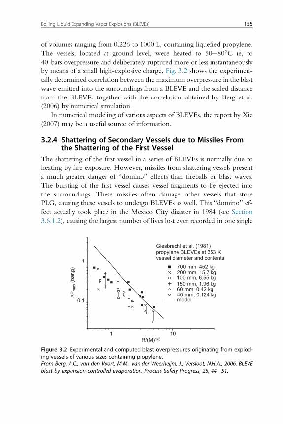
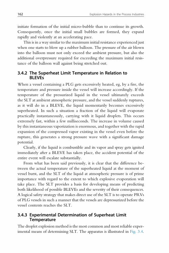
of volumes ranging from 0.226 to 1000 L, containing liquefied propylene.The vessels, located at ground level, were heated to 50e80�C ie, to40-bars overpressure and deliberately ruptured more or less instantaneouslyby means of a small high-explosive charge. Fig. 3.2 shows the experimen-tally determined correlation between the maximum overpressure in the blastwave emitted into the surroundings from a BLEVE and the scaled distancefrom the BLEVE, together with the correlation obtained by Berg et al.(2006) by numerical simulation.
In numerical modeling of various aspects of BLEVEs, the report by Xie(2007) may be a useful source of information.
3.2.4 Shattering of Secondary Vessels due to Missiles Fromthe Shattering of the First Vessel
The shattering of the first vessel in a series of BLEVEs is normally due toheating by fire exposure. However, missiles from shattering vessels presenta much greater danger of “domino” effects than fireballs or blast waves.The bursting of the first vessel causes vessel fragments to be ejected intothe surroundings. These missiles often damage other vessels that storePLG, causing these vessels to undergo BLEVEs as well. This “domino” ef-fect actually took place in the Mexico City disaster in 1984 (see Section3.6.1.2), causing the largest number of lives lost ever recorded in one single
Giesbrechl et al. (1981)propylene BLEVEs at 353 Kvessel diameter and contents
700 mm, 452 kg200 mm, 15.7 kg100 mm, 6.55 kg150 mm, 1.96 kg60 mm, 0.42 kg40 mm, 0.124 kgmodel
1 10R/(M)1/3
0.1
1
∆Pm
ax (b
ar,g
)
Figure 3.2 Experimental and computed blast overpressures originating from explod-ing vessels of various sizes containing propylene.From Berg, A.C., van den Voort, M.M., van der Weerheijm, J., Versloot, N.H.A., 2006. BLEVEblast by expansion-controlled evaporation. Process Safety Progress, 25, 44e51.
Boiling Liquid Expanding Vapor Explosions (BLEVEs) 155
explosion/fire accident in the process industry. Large parts of vessels can flyas projectiles over long distances. In one accident (Port Newark), a large partof a spherical vessel traveled more than 800 m before hitting and destroyinga petrol bunker.
According to Abbasi and Abbasi (2007), the likely consequence of aBLEVE series in terms of the duration and propagation of missiles dependson the following factors:• likely number and mass distribution of missiles• velocity and range distributions of missiles• likely directions of propagation of missiles• penetrability and destructive potential of missiles
3.2.5 Generation and Development of FireballsIf the liquid involved in the BLEVE is neither combustible nor toxic, as isthe case with water, the pressure wave and the missiles from the vessel shat-tering are the only hazardous effects of the explosion.
However, if the liquid is flammable, as is often the case, the mixture ofliquid/gas released by the explosion catches fire generating a fireball. Ana-lyses of actual BLEVEs have shown that more than two-thirds involvedflammable chemicals.
The shape and size of the fireball, and the heat load produced by it,depend on several factors. At the outset, the expelled mass of fuel canburn only at its periphery because there is not sufficient air inside themass, ie, the fuel/air mixture ratio is above the upper flammability limit.Furthermore, not all the fuel initially contained in the tank may becomeinvolved in the primary fire. Some of the liquid may leak to the surround-ings before the explosion via a crack or other opening in the vessel. Alter-natively, some of the liquid may be entrained in the wake formed byflying fragments. In the Mexico City disaster in 1984 (see Section3.6.1.2), fragments of shattered vessels carried with them parts of the flam-mable liquid, which in themselves caused the fires to spread.
As the main fireball from a BLEVE grows, the turbulence of the flameentrains air into the fireball. At the same time thermal radiation from theflame vaporizes liquid droplets and heats the combustible cloud. Becauseof all these processes, the entire cloud increases in volume, rises, and attainsan approximately spherical shape. Depending on the amount of combustiblematerial involved, such fireballs can become very large and cause veryintense thermal radiation. The size, lifetime, and radiation intensity of a
156 Explosion Hazards in the Process Industries
fireball may also depend on the initial temperature of the liquid originallycontained in the vessel. Whether the loss of confinement of the liquidoccurred while the pressure inside the vessel was still rising is a further factor.Although BLEVE fireballs are spherical when fully developed, they acquirea mushroom-like shape during lift-off.
Fireballs resulting from two-step BLEVEs (see definition later in thissection) may be approximately ellipsoidal in shape.
According to Lees (1996), it may happen that BLEVEs involvingcombustible materials are not ignited at the release point, but at a later stage.In such cases the resulting event may either be a major flash fire or a vaporcloud explosion.
3.2.6 Pool FiresSome of the liquid expelled from the shattered vessel may be splashed and hitthe ground nearby forming short-lived pools before vaporizing. In the caseof flammable liquids this may give rise to pool fires.
3.2.7 Emission of Toxic Gases/vaporsBLEVEs giving rise to emission of toxic substances have occurred with anumber of toxic compounds, such as ammonia, chlorine, chlorobutadiene,and phosgene. Of the one-third of recorded BLEVEs that did not involveflammable liquids, the majority involved toxic gases. Of these, chlorine(14%), ammonia (10%), and phosgene (2%) account for 76% of all BLEVEsinvolving nonflammables. With such chemicals, the fatalities were caused bythe toxic material expelled with the blast wave, and also by missiles. Accord-ing to Abbasi and Abbasi (2007), chlorine accounted for most of the fatalitiesin the major BLEVEs with noncombustible but toxic materials during1926e1981, followed by ammonia.
3.2.8 Emission of “Cold” Nontoxic GasesBLEVEs have occurred with tanks containing carbon dioxide and water,even in the absence of a fire. Abbasi and Abbasi (2007) suggested thatmany boiler explosions, which are far more common than explosionsinvolving other chemicals, are in fact BLEVEs, without being commonlyacknowledged and classified as such. Indeed, if all boiler explosions thatoccur with superheated water were to be included in the BLEVE statistics,it might well be that the most frequently involved liquid in BLEVEs turnsout to be water.
Boiling Liquid Expanding Vapor Explosions (BLEVEs) 157
3.2.9 Potential Consequences of BLEVEsThe energy of explosion, or “burst energy,” determines the severity of theblast wave generated by the BLEVE and the velocity (hence the range andthe penetration) of the shattered vessel fragments. The mode of release of thePLG in the shattered vessel determines the size, duration, and heat flux of thefireball if the PLG is flammable or it determines the pattern of atmosphericdispersion if the PLG is toxic. There is a much greater degree of uncertaintyassociated with predicting the consequences of BLEVEs than with predict-ing consequences of gas/vapor cloud explosions. This is because of the cen-tral roles played by superheated liquids and pressurized gases.
3.3 INDUCTION TIME PRECEDING BLEVEs:LONG-DURATION BLEVEs
Experience from accident histories has shown that some vesselsexploded within a few minutes of fire engulfment or missile hit, whereasothers did not explode until after several hours. In some cases, the inductiontime from fire engulfment or missile hit to vessel explosion was up to 24 h.In the Feyzin accident (see Section 3.6), the induction time was about90 min. In the Mexico City catastrophe (see Section 3.6), the inductiontimes varied between 3 and 30 min.
Clearly, having a good estimate of induction times in potential BLEVEsis important for optimization of damage control. Abbasi and Abbasi (2007)discussed a number of investigations aimed at quantifying induction times.For example, Blything and Reeves (1988) analyzed BLEVEs from horizontalcylinders filled to 75% of their capacity with liquid butane. The fire load waseither by partial fire engulfment or by jet flame impingement. From theiranalysis they concluded that a BLEVE would occur with induction timesbetween 4 and 48 min. In another investigation considering a full2000 tons PLG storage sphere being exposed to flames, Selway (1988) foundthat 7e11 min, 25e38 min, and 6e7 min were likely induction times in thecases of total fire engulfment, partial fire engulfment, and jet flame impinge-ment, respectively. According to Selway, these times would be shorter if thevessel is not completely filled with liquid.
In both fire-induced and missile collision-induced initial vessel damage,the first tear or crack may or may not propagate straight away to a sufficientsize to instantaneously cause a BLEVE. In some cases, an initial tear or crackthat is too small to directly initiate a BLEVE, may restart propagation againafter some time and increase to the size required to cause a BLEVE. Typicalcrack propagation speeds are then >200 m/s. About 20% of the BLEVEs
158 Explosion Hazards in the Process Industries
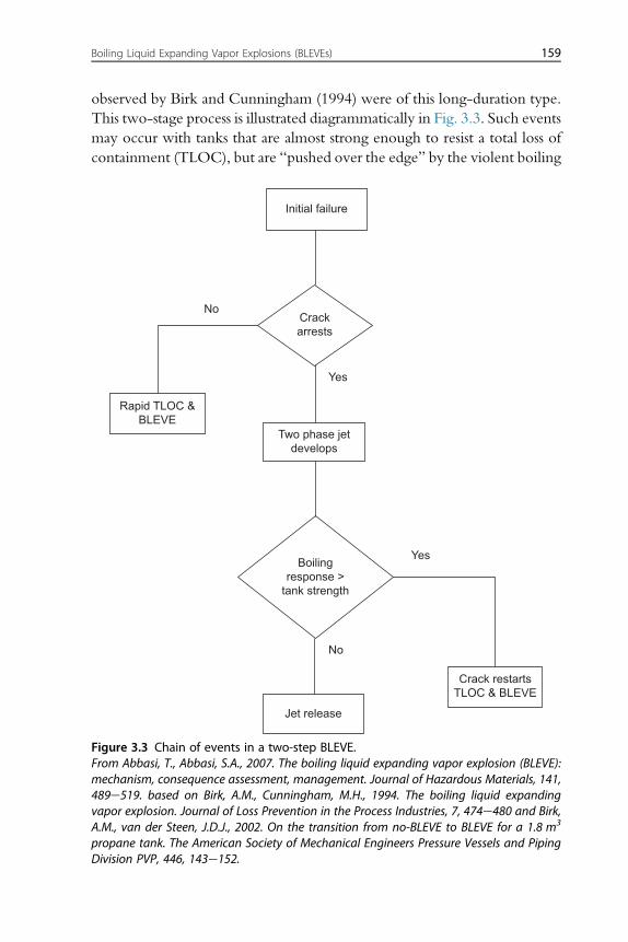
observed by Birk and Cunningham (1994) were of this long-duration type.This two-stage process is illustrated diagrammatically in Fig. 3.3. Such eventsmay occur with tanks that are almost strong enough to resist a total loss ofcontainment (TLOC), but are “pushed over the edge” by the violent boiling
Boiling
response >
tank strength
Crack
arrests
Crack restarts
TLOC & BLEVE
Jet release
Two phase jet
develops
Rapid TLOC &
BLEVE
Initial failure
No
No
Yes
Yes
Figure 3.3 Chain of events in a two-step BLEVE.From Abbasi, T., Abbasi, S.A., 2007. The boiling liquid expanding vapor explosion (BLEVE):mechanism, consequence assessment, management. Journal of Hazardous Materials, 141,489e519. based on Birk, A.M., Cunningham, M.H., 1994. The boiling liquid expandingvapor explosion. Journal of Loss Prevention in the Process Industries, 7, 474e480 and Birk,A.M., van der Steen, J.D.J., 2002. On the transition from no-BLEVE to BLEVE for a 1.8 m3
propane tank. The American Society of Mechanical Engineers Pressure Vessels and PipingDivision PVP, 446, 143e152.
Boiling Liquid Expanding Vapor Explosions (BLEVEs) 159
of the depressurization-induced superheated liquid. The occurrence oflong-duration BLEVEs are strongly related to the setting of the pressure re-lief valve (PRV), because this ultimately determines the liquid temperature.
Birk and Cunningham (1994, 1996) conducted a series of experimentswith 400 L propane tanks, subjecting the tanks to fire engulfment and study-ing the pattern and the duration of vessel failure. The tanks were equippedwith PRVs. Table 3.1 summarizes some results obtained by Birk andCunningham (1994).
In general, it is not possible to forecast how much time a vessel exposedto a fire may take before undergoing a BLEVE. This can vary from a fewseconds to several hours. This fact makes it very dangerous for firefightersto operate close to a fire-engulfed vessel containing a PLG/vapor. Therehave been many instances when a vessel has exploded even after the
Table 3.1 Summary of experimental results obtained by Birk and Cunningham(1994)
TestFireconditions
No. ofvents Outcome Comments
Vent to empty Pool only 5 Entire tank contentslost through thePRV
Fire conditionswere not severeenough to initiate alocal failure.
Pool andtorch
2
Partial failure Pool andtorch
7 Partial failureoccurred in the tankcausing a two-phaseliquid/vapourmixture to bereleased from thetank. In two casesthe jet was angledsuch that it propelledthe tank up to 30 m
Local thermalweakening wassuch that pressurestresses in the wallexceeded localtank wall strength,causing a failure(crack). The tankwall was strongenough to arrestthe crack
Torch only 4
TLOC andBLEVE
Pool andtorch
9 The tank failedcatastrophicallyreleasing the entirecontents asexpanding vapour,boiling liquid anddispersed droplets.Failures resulted inblasts and fireballs
Not all BLEVEswere the same
Torch only 2 The characteristicsof BLEVEsvaried with tankproperties andladingconditions at thetime of failure
160 Explosion Hazards in the Process Industries
PRVs have been venting the vessel for several minutes. Of all the harmfuleffects of BLEVEs, the one with the greatest impact is rocketing fragments.Often deaths of people quite a distance away from the site of the BLEVE andsecondary accidents in other process units, are caused by such missiles.
3.4 THE ROLE OF SUPERHEAT LIMIT TEMPERATUREOF THE LIQUID IN BLEVE DEVELOPMENT
3.4.1 Boiling and Boiling Points of LiquidsIn the context of BLEVEs it is essential to distinguish between the two
different boiling points of a liquid, viz. its normal boiling point (BP) and itsSLT. The SLT of a liquid is quite different from its BP. The basic definitionof BP, as experienced in normal cooking, is the temperature at which theliquid’s vapor pressure equals the ambient pressure above the liquid surface,plus the liquid head above the point in the liquid being considered. There-fore, a given liquid in an evacuated environment has a lower boiling pointthan when the same liquid is at atmospheric pressure. If the liquid is in anenvironment of pressure above atmospheric, it will have a higher boilingpoint than at atmospheric pressure. For vapor bubbles to form and expandin normal cooking, the presence of “active points” at the bottom and/orwall of the cooking device or on impurities in the liquid is essential. Suchpoints can be sharp edges, scratches or pores in the surface, or small solid par-ticles adhering to the surface. The function of an “active point” is to allow avapor bubble to form without being fully embraced by a liquid/vaporinterface.
A pure liquid, with no “active points,” can be heated to a temperatureconsiderably higher than its boiling point at the prevailing pressure beforesignificant boiling starts. This temperature is called the “superheat limit tem-perature” (SLT), which is synonymous with the alternative term “homoge-neous nucleation temperature.” In the absence of “active points,” fullyenclosed vapor bubbles must become formed within the pure liquid. Inthis case the surface tension of the liquid at the liquid/bubble interfacewill suppress the transfer of liquid molecules into vapor phase molecules.Therefore, a pure enclosed liquid that is free from “active points” willhave to get heated to above its normal boiling point before the vapor pres-sure becomes sufficiently high for onset of boiling. The excess temperatureand hence liquid vapor pressure required to overcome the surface tension ofa bubble wall in a liquid is inversely proportional to the bubble diameter. Inthe absence of “active points,” therefore, a higher pressure is required to
Boiling Liquid Expanding Vapor Explosions (BLEVEs) 161
initiate formation of the initial micro-bubble than to continue its growth.Consequently, once the initial small bubbles are formed, they expandrapidly and violently at an accelerating pace.
This is in a way similar to the maximum initial resistance experienced justwhen one starts to blow up a rubber balloon. The pressure of the air blowninto the balloon must not only exceed the ambient pressure, but also theadditional overpressure required for exceeding the maximum initial resis-tance of the balloon wall against being stretched out.
3.4.2 The Superheat Limit Temperature in Relation toBLEVEs
When a vessel containing a PLG gets excessively heated, eg, by a fire, thetemperature and pressure inside the vessel will increase accordingly. If thetemperature of the pressurized liquid in the vessel ultimately exceedsthe SLT at ambient atmospheric pressure, and the vessel suddenly ruptures,as it will do in a BLEVE, the liquid momentarily becomes excessivelysuperheated. In such a situation a fraction of the liquid will evaporatepractically instantaneously, carrying with it liquid droplets. This occursextremely fast, within a few milliseconds. The increase in volume causedby this instantaneous vaporization is enormous, and together with the rapidexpansion of the compressed vapor existing in the vessel even before therupture, this generates a strong pressure wave with a significant damagepotential.
Clearly, if the liquid is combustible and its vapor and spray gets ignitedimmediately after a BLEVE has taken place, the accident potential of theentire event will escalate substantially.
From what has been said previously, it is clear that the difference be-tween the actual temperature of the superheated liquid at the moment ofvessel burst, and the SLT of the liquid at atmospheric pressure is of primeimportance with regard to the extent to which explosive evaporation willtake place. The SLT provides a basis for developing means of predictingboth likelihood of possible BLEVEs and the severity of their consequences.A logical safety strategy that makes direct use of the SLT is to operate PRVsof PLG vessels in such a manner that the vessels are depressurized before thevessel contents reaches the SLT.
3.4.3 Experimental Determination of Superheat LimitTemperature
The droplet explosion method is the most common and most reliable exper-imental means of determining SLT. The apparatus is illustrated in Fig. 3.4.
162 Explosion Hazards in the Process Industries
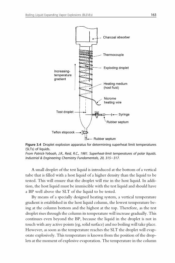
A small droplet of the test liquid is introduced at the bottom of a verticaltube that is filled with a host liquid of a higher density than the liquid to betested. This will ensure that the droplet will rise in the host liquid. In addi-tion, the host liquid must be immiscible with the test liquid and should havea BP well above the SLT of the liquid to be tested.
By means of a specially designed heating system, a vertical temperaturegradient is established in the host liquid column, the lowest temperature be-ing at the column bottom and the highest at the top. Therefore, as the testdroplet rises through the column its temperature will increase gradually. Thiscontinues even beyond the BP, because the liquid in the droplet is not intouch with any active points (eg, solid surface) and no boiling will take place.However, as soon as the temperature reaches the SLT the droplet will evap-orate explosively. This temperature is known from the position of the drop-lets at the moment of explosive evaporation. The temperature in the column
Figure 3.4 Droplet explosion apparatus for determining superheat limit temperatures(SLTs) of liquids.From Patrick-Yeboah, J.R., Reid, R.C., 1981. Superheat-limit temperatures of polar liquids.Industrial & Engineering Chemistry Fundamentals, 20, 315e317.
Boiling Liquid Expanding Vapor Explosions (BLEVEs) 163
as a function of vertical position is monitored by means of a thermocouplethat can be positioned at any desired point in the column.
One problem inherent in the droplet explosion technique is that theinitial unstable bubble nuclei being formed when the temperature ap-proaches SLT have sizes on the molecular scale. It is likely, therefore, thateven in the most careful experiments, microscopic temperature gradientsin the liquid could initiate formation of bubbles at a global liquid tempera-ture significantly below the superheat limit. Another concern is whether theglobal droplet temperature is actually equal to that of the surrounding liquidat any time during the rise of the droplet. The temperature difference willdepend on the droplet size, the droplet rise velocity, the steepness of the ver-tical temperature gradient in the host liquid column, and the heat conduc-tivity of the droplet liquid. Nevertheless, the droplet explosion technique isthe best method currently available for experimental determination of SLT.
Another experimental method for determining SLT is based on immer-sion of very thin and rapidly electrically heated wires in a very clean testliquid. The temperature of the wire is recorded continuously as the wireis heated up. As soon as the wire temperature has reached the SLT of theliquid, the liquid layer adjacent to the wire will vaporize explosively. Thisapproach requires that the dynamics of the thermocouple/temperaturemeasuring device must be faster than the dynamics of the heating of thewire. The nature of the wire surface also influences nucleation. This methodalso gives fairly reproducible results, but it is considered less accurate than therising-bubble method.
In Table 3.2, from Salla et al. (2006), the boiling points, the SLTs, andthe critical temperatures are given for a selection of substances.
Table 3.3 is based on data from Wakeshima and Takata (1958). Thetheoretical SLT values were calculated using the classical D€oring theory.
3.4.4 The Role of Superheat Limit Temperature in BLEVETheories
3.4.4.1 OverviewAs pointed out by Abbasi and Abbasi (2007), several complex questionsrelated to BLEVEs call for theories that can predict both the developmentand consequences of such events in given practical situations.
In most theories on the development of BLEVEs, the SLT plays a centralrole. Clearly, this is because the explosive volumetric boiling of liquids attemperatures above the SLT at atmospheric pressure is so much more violentthan boiling below SLT.
164 Explosion Hazards in the Process Industries
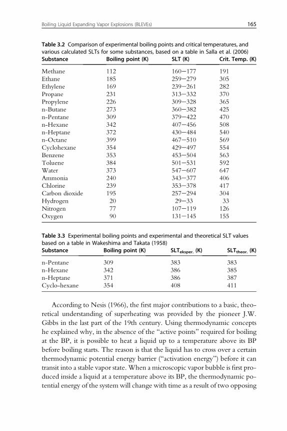
According to Nesis (1966), the first major contributions to a basic, theo-retical understanding of superheating was provided by the pioneer J.W.Gibbs in the last part of the 19th century. Using thermodynamic conceptshe explained why, in the absence of the “active points” required for boilingat the BP, it is possible to heat a liquid up to a temperature above its BPbefore boiling starts. The reason is that the liquid has to cross over a certainthermodynamic potential energy barrier (“activation energy”) before it cantransit into a stable vapor state. When a microscopic vapor bubble is first pro-duced inside a liquid at a temperature above its BP, the thermodynamic po-tential energy of the system will change with time as a result of two opposing
Table 3.2 Comparison of experimental boiling points and critical temperatures, andvarious calculated SLTs for some substances, based on a table in Salla et al. (2006)Substance Boiling point (K) SLT (K) Crit. Temp. (K)
Methane 112 160e177 191Ethane 185 259e279 305Ethylene 169 239e261 282Propane 231 313e332 370Propylene 226 309e328 365n-Butane 273 360e382 425n-Pentane 309 379e422 470n-Hexane 342 407e456 508n-Heptane 372 430e484 540n-Octane 399 467e510 569Cyclohexane 354 429e497 554Benzene 353 453e504 563Toluene 384 501e531 592Water 373 547e607 647Ammonia 240 343e377 406Chlorine 239 353e378 417Carbon dioxide 195 257e294 304Hydrogen 20 29e33 33Nitrogen 77 107e119 126Oxygen 90 131e145 155
Table 3.3 Experimental boiling points and experimental and theoretical SLT valuesbased on a table in Wakeshima and Takata (1958)Substance Boiling point (K) SLTeksper. (K) SLTtheor. (K)
n-Pentane 309 383 383n-Hexane 342 386 385n-Heptane 371 386 387Cyclo-hexane 354 408 411
Boiling Liquid Expanding Vapor Explosions (BLEVEs) 165
simultaneous processes. The potential energy will increase because surfaceenergy is accumulated at the interface between the liquid and the vapor bub-ble. However, when the unstable molecules in the liquid state transit to themore stable vapor state, the potential energy will decrease. For very small,microscopic bubbles the first effect is dominating, whereas the latter effecttakes over as the bubbles grow. Therefore, there is a given critical micro-scopic bubble size at which the thermodynamic potential of the system rea-ches a maximum. As soon as the bubble has grown beyond this critical size, itwill grow further spontaneously. The minimum liquid temperature that al-lows this critical bubble size to be reached is per definition the SLT of theliquid (cfr. The rubber balloon analogy at the end of Section 3.4.1). Justas with the BP, the SLT also varies with the pressure of the environmentin which the liquid is kept. However, in the context of BLEVEs, the SLTfor ambient atmospheric pressure is of prime importance and significance.Hence, when the acronym SLT is used in the following, it generally meansSLT at ambient atmospheric pressure.
3.4.4.2 SLT Is Not an Absolute Lower Temperature Limit for BLEVEsto Occur
Comprehensive research conducted by Birk and coworkers has revealed thatthe SLT is not an absolute lower temperature limit for a BLEVE to occur.Depending on the circumstances leading to vessel rupture, BLEVEs canoccur even at temperatures significantly below the SLT. It is clear, however,that the blast overpressures generated by such BLEVEs will be considerablylower than those produced by BLEVEs occurring above the SLT.
3.4.4.3 Flammable Liquids Giving Rise to FireballsThe size, shape, and radiation intensity of the fireballs which are formedwhen flammable liquids undergo BLEVEs do not appear directly relatedto the extent to which the liquid is superheated.
3.4.4.4 Theory of Boiling-Liquid-Collapsed-Bubble ExplosionAccording to Abbasi and Abbasi (2007), the understanding of the BLEVEprocess has been further refined by careful analysis of some more recentBLEVE accidents, followed up by controlled experiments. One conclusionis that all BLEVEs are in fact the result of a more or less universal two-stageprocess. The first step is the formation of a limited crack in the vessel wall,giving rise to a moderate initial leak (“leak before break”). In the secondstep, there will be waves of repeated depressurization and repressurization
166 Explosion Hazards in the Process Industries
caused by further crack propagation and evaporation and ejection of fluid,leading to the final major failure. The delay time between crack initiationand catastrophic failure depends on how much of the vessel volume isinitially filled with liquid. A typical delay time for 20% filling is 40 s andfor 85% filling 1.4 s.
3.5 PROPERTIES AND EFFECTS OF FIREBALLSFROM BLEVEs
Bosch and Weterings (1997) defined a fireball as a fire that burns withsufficient rapidity for the burning mass to raise into the air as a cloud or ball.In all BLEVEs involving combustible liquids there is an almost instantaneoustwo-phase release of most of the liquid which immediately auto-ignites toform the fireball. Therefore, the fireball is more or less an inevitable conse-quence whenever a vessel containing a flammable liquid suffers a BLEVE.For this reason, the fireball is often considered an inherent part of anyBLEVE. However, about one-fifth of all BLEVEs occur with nonflammableliquids (including fire suppressants like nitrogen, carbon dioxide, and water),and obviously no fireball is generated in such cases.
Although fireballs from BLEVEs are predominantly influenced by mo-mentum forces, fireballs generated when more stagnant vapor clouds areignited are mostly moved by buoyancy forces.
In some rare cases a vessel containing a flammable PLG may first release asufficient mass of vapor to generate a vapor cloud that gets ignited before thevessel fails in a BLEVE that generates a much bigger fireball. According toMakhviladze, Roberts, and Yakush (1999), the fireball from a BLEVEreleasing 100 tons of flammable liquid hydrocarbon develops about5 � 1012 J of thermal energy within 10e20 s. A significant part of this en-ergy appears as thermal radiation, which is powerful enough to scorch peo-ple, damage property, and trigger secondary fires.
Frame-by-frame analysis of full-scale fireball records conducted byCrawley (1982) show that the fireball passes through three phases, viz.growth, steady burning, and burn-out. The growth phase comprises twotime intervals, each of about 1 s. During the first interval, the fireball growsto about half its final diameter, and the fireball boundary is brightyellowish-white, indicating a flame temperature of about 1300�C. In thesecond time span of the first phase, the fireball attains its maximum volume,but about 10% of the surface is now dark and sooty, whereas the major 90%is white, yellowish-orange or light red, indicating flame temperatures in the
Boiling Liquid Expanding Vapor Explosions (BLEVEs) 167
range 900e1300�C, with an estimated effective average flame temperatureof 1100e1200�C.
In the second steady-burning phase, which lasts for some 10 s, the fire-ball, which is now roughly spherical, is no longer growing. At the start ofthis phase it begins to lift off, rises, and attains the characteristic mush-room shape. The estimated average effective flame temperature remains at1100e1200�C.
In the third burn-out phase, which typically lasts for about 5 s, the fire-ball size remains constant, but the flame becomes less sooty and moretranslucent.
According to Abbasi and Abbasi (2007), the following issues must beaddressed to enable prediction of the size and duration of a fireball, andthe thermal radiation from it:• mass of flammable substance released in the BLEVE• mass of flammable substance consumed in the fireball• fireball development as a function of time• fireball full size and duration• radiation heat load generated• view factor
Bosch and Weterings (1997) presented the following list of items thatneed to be quantified to enable estimation of the thermal radiation impactof a BLEVE fire-ball:• amount of flammable material released in BLEVE• heat generated by the fireball• fireball radius• fireball duration• fireball lift-off height• radiated heat flux• net available heat for thermal radiation• radiation absorption by water vapor between fireball and point of impact• radiation absorption by carbon dioxide between fireball and point of
impact• atmospheric transmissivity• distance from center of fireball to actual point of impact• “view factor” at point of impact
Bosch and Weterings (1997) defined the “view factor” as the ratiobetween the received and the emitted radiation energy per unit area, orthe fraction of the fireball that is “seen” by the target at the point of impact.
168 Explosion Hazards in the Process Industries
The view factor incorporates the orientation of the object relative to thefireball, as well as its distance from the fireball center.
As is the case with predicting the other BLEVE impact parameters,considerable uncertainty is also to be expected in the estimation of the ther-mal parameters of fireballs. These problems appear right from the initialassessment of the amount of combustible material (the “flashing fraction”)that is released instantaneously on vessel failure. Bosch and Weterings(1997) assume that the entire vessel content will flash over and contributeto the fireball, whereas Marshall (1987) and others assume that the fractionof the fuel that participates in the fireball is only about one-third of the totalamount released in the BLEVE.
3.6 BLEVE CASE HISTORIES
This section is based on the extensive review by Abbasi and Abbasi(2007).
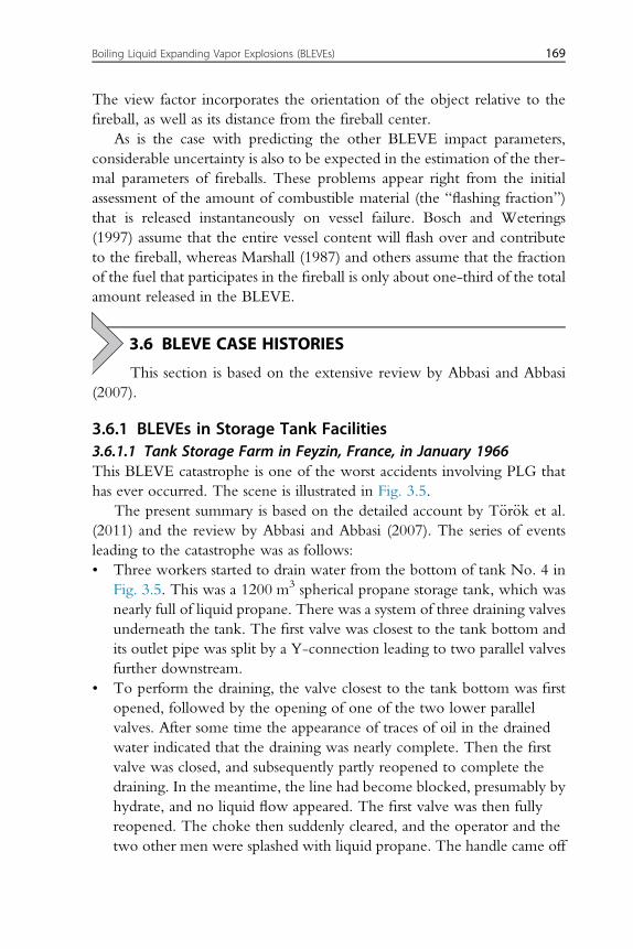
3.6.1 BLEVEs in Storage Tank Facilities3.6.1.1 Tank Storage Farm in Feyzin, France, in January 1966This BLEVE catastrophe is one of the worst accidents involving PLG thathas ever occurred. The scene is illustrated in Fig. 3.5.
The present summary is based on the detailed account by T€or€ok et al.(2011) and the review by Abbasi and Abbasi (2007). The series of eventsleading to the catastrophe was as follows:• Three workers started to drain water from the bottom of tank No. 4 in
Fig. 3.5. This was a 1200 m3 spherical propane storage tank, which wasnearly full of liquid propane. There was a system of three draining valvesunderneath the tank. The first valve was closest to the tank bottom andits outlet pipe was split by a Y-connection leading to two parallel valvesfurther downstream.
• To perform the draining, the valve closest to the tank bottom was firstopened, followed by the opening of one of the two lower parallelvalves. After some time the appearance of traces of oil in the drainedwater indicated that the draining was nearly complete. Then the firstvalve was closed, and subsequently partly reopened to complete thedraining. In the meantime, the line had become blocked, presumably byhydrate, and no liquid flow appeared. The first valve was then fullyreopened. The choke then suddenly cleared, and the operator and thetwo other men were splashed with liquid propane. The handle came off
Boiling Liquid Expanding Vapor Explosions (BLEVEs) 169
the valve and it was impossible to get it back in place. The lower valvehad become frozen and could not be closed. Access to the valve area wasdifficult because the valves were immediately below the tank bottom,which was only 1.4 m above the ground.
• The propane leak was now completely out of control and soon formed alarge visible 1 m thick vapor/mist cloud, which spread out across theground as a layer of radius of 150 m.
• Twenty-five minutes after the leak had started the large vapor cloud wasignited by an automobile that had stopped on a nearby road. The fireflashed back to the storage tank and continued to burn there, but therewas no immediate explosion.
• The tank was equipped with a water deluge system but the water supplywas inadequate for cooling the tank. Furthermore, as soon as the firebrigade began to use their hoses, the water supply to the deluge systemran dry. Apparently the firemen had used up the available water forcooling the neighboring tanks to prevent the fire from spreading tothem. They may have assumed that the tank on fire was protected suf-ficiently by the opened relief valve.
• Ninety minutes after the fire started, the tank BLEVEed.
Figure 3.5 Tank farm at Feyzin, France, consisting of four spherical tanks of capacity1200 m3 each, four spherical tanks of capacity 2000 m3 each, and two horizontal cylin-drical tanks of capacity 150 m3 each.From T€or€ok, Z., Ajtai, N., Turcu, A.-T., Ozunu, A., 2011. Comparative consequence analysisof the BLEVE phenomena in the context of land use planning. Case study: The Freyzinaccident. Process Safety and Environmental Protection, 89, 1e7.
170 Explosion Hazards in the Process Industries
Ten of the 12 firemen operating within 50 m from the tank werekilled. People 140 m away were badly burned by a wave of propane whichpassed over the compound wall. Altogether, 15e18 men were killed andabout 80 injured. Flying debris broke the legs of an adjacent sphericaltank which fell over. Its relief valve discharged combustible liquid whichadded to the fire, and 45 min later even this tank BLEVEed. Altogether,five spherical and two other pressure vessels ruptured catastrophically,whereas three suffered less severe damage. The fire also spread to gasolineand fuel oil tanks.
3.6.1.2 PEMEX PLG Terminal Catastrophe in Mexico City,in November 1984
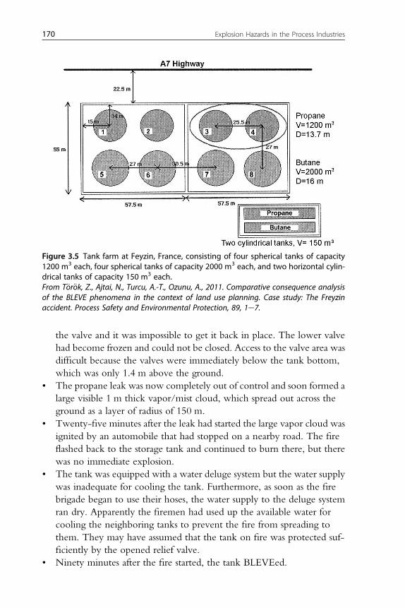
The large Petroleos Mexicanos (PEMEX) PLG terminal in San Juan Ixhua-tepec, Mexico City, received supplies from three different gas refineriesevery day. In the morning of the accident, the vessels at the terminalwere being filled with PLG arriving in a pipeline from a refinery 400 kmaway. Then a drop in pipeline pressure occurred due to the rupture of an8-in. pipe that connected one of the storage spheres to a series of cylindricaltanks. However, the operators did not imagine such a possibility and therelease of the PLG from the leaking pipeline continued for 5e10 min.This led to the major catastrophe illustrated in Fig. 3.6.
The escaping gas formed a 2-m high cloud covering an area of200 m � 150 m, which drifted toward a flare tower where it caught fireand prepared the ground for the first BLEVE in a series of several.
Four spherical tanks, each containing 1500 m3 of PLG, and severalsmaller cylindrical tanks containing between 45 and 270 m3 PLG each suf-fered BLEVEs. All the BLEVEs generated fireballs, which raged throughthe streets of Ixhuatepec for about 90 min. A block of perhaps 200 housesbuilt mostly of wood, cardboard, and metal sheets was demolished by thesefireballs. Masses of fragments of tanks and pipes weighing up to40 tons, were blown into the air and landed as far away as 1200 m. TheBLEVEs ejected fragments of four of the six larger spherical tanks. Thefragments were wrapped in burning PLG and rocketed in all directions.Some of the fragments hit other vessels which were also damaged. Otherfragments initiated local fires which engulfed other vessels. Fifteen of the48 smaller cylindrical vessels were ejected as “bullets” into the surround-ings. Fig. 3.6 indicates some vessel fragments and “bullets” retrieved afterthe accident.
The disaster caused about 650 deaths and more than 6400 injuries. Theentire PEMEX terminal was devastated. The total damage was estimated atmore than 30 million US$.
Boiling Liquid Expanding Vapor Explosions (BLEVEs) 171
3.6.1.3 Boral PLG Distribution Depot in Sydney, Australia,in April 1990
In the evening of April 1, 1990, a BLEVE occurred in the Boral PLG stor-age/distribution terminal outside Sydney. This led to a series of furtherBLEVEs throughout the night.
The first event was an explosion of a small gas tank. The resulting firethen spread along ruptured gas pipes to the four main 100-tons steel PLGstorage tanks containing at total of at least 40,000 L of PLG. The fire heatedup the tanks until the 15-cm thick steel walls failed and gave rise to verypowerful BLEVEs. The resulting fireballs and gas flares extended hundredsof meters into the sky. Hundreds of portable gas cylinders of capacitiesfrom 2 to 240 kg, and kept inside a storage room at Boral, also BLEVEd.
Figure 3.6 Site of the Mexico City BLEVE catastrophe.From Marshall, V.C., 1987. Major Chemical Hazards, Elis Horwood Series in ChemicalEngineering, Ellis Horwood Ltd/Halsted Press, A Division of John Wiley & Sons, Chichester/New York, ISBN:0-470-20813-9.
172 Explosion Hazards in the Process Industries
Power blackouts occurred after the first thundering explosion, which shat-tered windows. The shock wave from one of the BLEVEs uprooted a tele-graphic pole that was shot away as a missile and nearly hit a woman who wasstanding almost 500 m away from the exploding vessel. One of a number of30-m long cylinders blew off its mooring and rocketed through the air witha tail of flames. Upon landing it created a 2-m diameter crater in the earth,before bouncing through a wire fence into three 40-ton tanks, which werepropelled into a nearby canal. The rocketing cylinder then hit and flattenedan electrical substation and a panel-beating workshop before diving into thecanal 300 m away from its original position.
Fortunately it all happened on a Sunday. The loss of human lives andnumber of injuries would have been substantially larger if the accidenthad occurred on a working day. In addition, a favorable wind directioncontributed to limiting the spread of the fire. The chain of BLEVEs waseventually broken when Boral engineers were able to open the relief safetyvalves of the surviving tanks to depressurize them.
Several factory storage buildings close to the explosion sites weredestroyed. The buildings that survived had doors that were thrown off theirhinges, roofs that lifted and windows that shattered. The Boral plant wasbuilt in 1968 to satisfy standards that were outdated by the time of the ex-plosion disaster in 1990.
3.6.1.4 A Supercritical Pressure BLEVE in Nihon Dempa KogyoCrystal Inc.
Zhang et al. (2014) describe a BLEVE accident that occurred on December7, 2009 at the Nihon Dempa Kogyo Crystal (NDK) Inc. facility inBelvidere, Illinois, United States. A 15-m high pressure vessel rupturedand as a result a number of fragments were ejected from the facility, killinga truck driver 200 m away and injuring an employee inside a building130 m away. The US Chemical Safety and Hazard Investigation Board-concluded that stress corrosion cracking was the mechanism causing thevessel failure. After analyzing the operating conditions and the conse-quences, the accident was classified as a supercritical BLEVE. A conse-quence analysis of the accident was performed, including estimation ofblast wave overpressure, fragment travel distances, and safety distances.Some important root causes, such as poor safety culture, poor managementwithin the mother company, and poor communication between the actualfacility being hit by the accident and official authorities, were alsoidentified.
Boiling Liquid Expanding Vapor Explosions (BLEVEs) 173
3.6.2 BLEVEs in PLG and CNG Transportation Facilities3.6.2.1 Highway Tunnel Near Palermo, Italy, March 1996A tank truck became involved in a car crash inside a highway tunnel. Theinitiating event was the skidding of a car inside the tunnel causing piling-upof cars behind it. The engine of one of the cars caught fire as a result of acollision with another car. The tank truck also entered the tunnel but hadto stop about 50 m from the tunnel exit to avoid collision with the carsahead. However, a bus just behind the tank truck arrived at high speed,skidded and crashed into the truck, causing a leakage in the upper partof the tank shell, just below the manhole. A few seconds later a “softrumble” was heard, followed by a “hot wind” that caused serious burnsto the people in the tunnel. Most of the people in the tunnel, except forfive persons who had fainted as a result of the crash, managed to run outof the tunnel. Four minutes later, the tank of the tank truck BLEVEd.The resulting blast wave demolished the cars in the tunnel and killed thefive persons who had been unable to escape. Dense black smoke wasexpelled from the tunnel exit.
3.6.2.2 Highway near Tivissa, Spain, June 2002A tank vehicle carrying compressed natural gas (CNG) lost control on adownhill road and turned over. When it came to a halt beside a sandy slope,flames appeared between the truck cabin and the trailer due to ignition ofeither leaking diesel, or CNG, or perhaps both. The fire increased in size,perhaps due to involvement of CNG escaping from the PRV. There wasa small explosion, followed by a strong hissing sound. Then the tankBLEVEd and the ejected CNG ignited, giving rise to a huge fireball. Theaccident occurred in a remote location, but it nevertheless led to one casu-alty and burn injuries to two persons who were about 200 m away from theblast site.
3.6.3 BLEVEs in Stationary Installations Containing Toxic butNonflammable Chemicals
3.6.3.1 Phosgene Storage Tank, Hamburg, Germany, May 1928A tank containing phosgene BLEVEd at a factory near the harbor area ofHamburg, Germany. About 12 tons of the deadly gas was released intothe atmosphere. Eleven people were killed and 171 injured. People wereaffected by the gas at locations up nearly 20 km from the accident site. Ifthe wind had blown over populated areas, the fatalities would have beenmuch higher.
174 Explosion Hazards in the Process Industries
3.6.3.2 Colorant Manufacturing Unit, Louisville, Kentucky, UnitedStates, April 2003
A tank containing a mixture of maltodextrin and water was unintentionallyoverheated. On two earlier occasions, the tank had been deformed due tomisapplication of vacuum, and the repairs had not been certified to meetstandard requirements for structural strength. Most probably, this was thecause of the tank failure, as the internal overpressure at the time of vesselburst was less than the formal design pressure of the tank. The explosion pro-pelled the top head of the tank to about 100 m away from the original site,and one operator lost his life. The main tank shell was ejected off its foun-dation and struck a 50,000 L liquid ammonia storage tank, which wasknocked it sideways and ruptured, giving rise to a 12,000 kg leak. The shellthen ricocheted and hit the bottom of a five-story spray drier, whichtoppled.
3.6.4 BLEVEs During Transportation of Toxic butNonflammable Chemicals
3.6.4.1 Tractor Tank Carrying Ammonia, Houston, United States,May 1976
A tractor tank semitrailer carrying 19 tons of liquid anhydrous ammoniaaccidentally went through a bridge rail on an interstate highway and fellabout 5 m onto a freeway, on which, at the time of the accident, the trafficwas quite heavy. The tank BLEVEd and the liquid ammonia flashed off,forming a 30-m high cloud. The cloud gradually mixed with the ambientair and finally attained a width of about 300 m and a length of about600 m. It was estimated that the evaporation of the ammonia and the sub-sequent mixing with air occurred within 5 min. The driver of the truck andfive other people were killed. Seventy-eight people had to be taken to hos-pital for injury treatment, whereas about another 100 suffered less severe in-juries. Five of the six casualties were due to the toxic effect of ammonia.
3.6.4.2 Freight Train Transporting Chlorine, Montana, Mexico, 1981A train comprising 38 wagons, including 32 rail tank cars filled with liquidchlorine, was moving down a steep and winding valley at a 3% gradientwhen its brakes failed. The train derailed at over 80 km/h on a bend350 m beyond Montana station, resulting in a pile-up that included 28 ofthe 32 chlorine cars. Most were badly damaged and suffered BLEVEs oneafter another. One tank car lost its dished end and the shell was propelled2000 m. A second was split along its side. A third had a 0.5-m diameter
Boiling Liquid Expanding Vapor Explosions (BLEVEs) 175
hole, probably the result of an ironechlorine fire, which could well haveresulted from ignition of the cork insulation by red-hot brakes. Four othertank cars suffered damage to their valves, which were ripped off or dislodgedso that they leaked. It is estimated that 100 tons of chlorine escaped in thefirst few minutes and 300e350 tons in all.
17 persons died, 4 in the caboose of the train and 13 from gassing. Inaddition about 1000 people were injured. The vegetation up the valleywas bleached by the gas cloud passing up it; there was also discolorationsome 50 m down the slope and up the sides for a vertical distance of about50 m. The highest concentrations appear to have occurred in a strip 1000 mlong � 40 m wide.
3.6.5 BLEVEs Involving Only Nonflammable and NontoxicChemicals
3.6.5.1 Liquid Nitrogen Storage Vessel in Japan, August 1992The catastrophic failure of a storage vessel containing liquid nitrogenresulted in a BLEVE causing demolition of almost half of the factory,damaging the walls of 25 houses and destroying 39 cars, buses, and trucks,all within a 400 m radius of the original site of the storage vessel. Fragmentsof the vessel, including part of the 150-cm wide and 8-mm thick top head ofthe outer shell were ejected up to 350 m away from the original site. Theestimated property loss was $5 million.
3.6.5.2 Mihama Nuclear Power Reactor, Japan, August 2004A large pipe carrying superheated water started to leak and exploded. Theresulting two-phase release of superheated water and steam scorched 11workers. Some of these lost their lives; the others were severely injured.
3.6.6 Initiating Events Leading to BLEVEs in Case Histories3.6.6.1 Relative Frequencies of Initiating EventsAbbasi and Abbasi (2007) were not able to trace any comprehensive, system-atic record of BLEVEs that have occurred worldwide. However, from avail-able published evidence, they deduced the relative frequencies of theinitiating events leading to 88 major BLEVEs that occurred during theperiod 1926e2007. The results are summarized in Table 3.4. The frequencydistribution given in the table refers to the initial causes leading to the veryfirst BLEVE in an accident, irrespective of whether the accident alsocomprised several subsequent BLEVEs. However, more than one BLEVEs
176 Explosion Hazards in the Process Industries
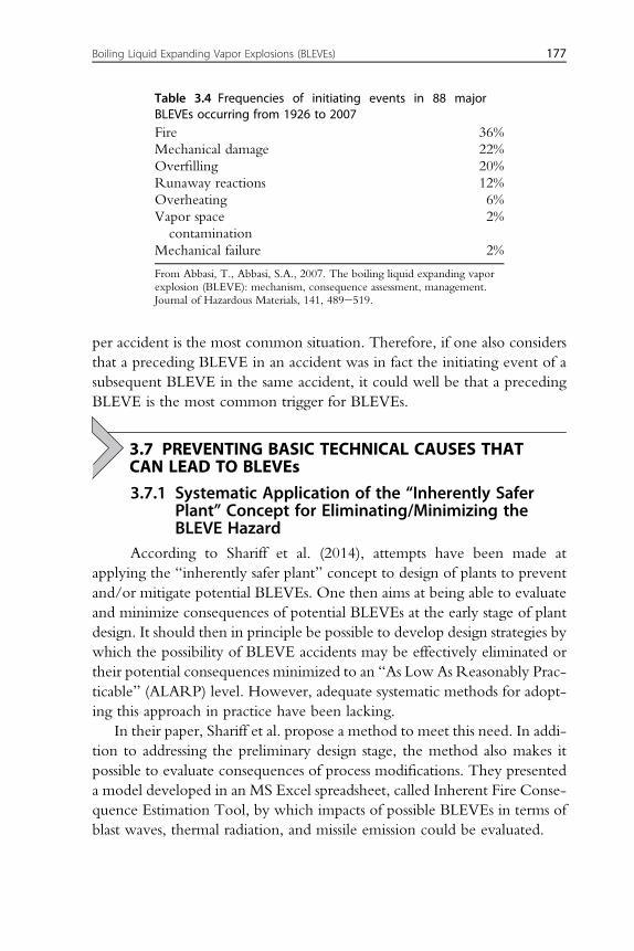
per accident is the most common situation. Therefore, if one also considersthat a preceding BLEVE in an accident was in fact the initiating event of asubsequent BLEVE in the same accident, it could well be that a precedingBLEVE is the most common trigger for BLEVEs.
3.7 PREVENTING BASIC TECHNICAL CAUSES THATCAN LEAD TO BLEVEs
3.7.1 Systematic Application of the “Inherently SaferPlant” Concept for Eliminating/Minimizing theBLEVE Hazard
According to Shariff et al. (2014), attempts have been made atapplying the “inherently safer plant” concept to design of plants to preventand/or mitigate potential BLEVEs. One then aims at being able to evaluateand minimize consequences of potential BLEVEs at the early stage of plantdesign. It should then in principle be possible to develop design strategies bywhich the possibility of BLEVE accidents may be effectively eliminated ortheir potential consequences minimized to an “As Low As Reasonably Prac-ticable” (ALARP) level. However, adequate systematic methods for adopt-ing this approach in practice have been lacking.
In their paper, Shariff et al. propose a method to meet this need. In addi-tion to addressing the preliminary design stage, the method also makes itpossible to evaluate consequences of process modifications. They presenteda model developed in an MS Excel spreadsheet, called Inherent Fire Conse-quence Estimation Tool, by which impacts of possible BLEVEs in terms ofblast waves, thermal radiation, and missile emission could be evaluated.
Table 3.4 Frequencies of initiating events in 88 majorBLEVEs occurring from 1926 to 2007Fire 36%Mechanical damage 22%Overfilling 20%Runaway reactions 12%Overheating 6%Vapor spacecontamination
2%
Mechanical failure 2%
From Abbasi, T., Abbasi, S.A., 2007. The boiling liquid expanding vaporexplosion (BLEVE): mechanism, consequence assessment, management.Journal of Hazardous Materials, 141, 489e519.
Boiling Liquid Expanding Vapor Explosions (BLEVEs) 177
3.7.2 Preventing Pressurized Liquefied Gas-containingVessels From Becoming Exposed to Fires
3.7.2.1 Keeping PLG-containing Vessels at Safe Distances FromLikely Sources of Fire
Fire engulfment is the most common basic technical cause of BLEVEs.Therefore, it is very important that PLG-containing vessels be located at suf-ficiently long distances from each other and from any other potential sourcesof fire.
3.7.2.2 Sloping of the Nearby GroundTo prevent a pool fire from occurring after an accidental spill from a fixedPLG vessel, the ground around the vessel should have a downward slope ofat least 1% so to enable the spill to flow away to a safe area.
3.7.2.3 Water BarriersFacilities for generating water mist barriers close to PLG vessels can beinstalled. Such barriers can capture any flammable vapor released from aPGL-vessel and disperse it without the flammable vapor getting ignited.In the case of water-soluble toxic substances like ammonia and chlorine,the water will dissolve some of the released material and thereby reducethe amount of toxic material that remains dispersed in the air.
3.7.3 Preventing Mechanical Damage of PressurizedLiquefied Gas-containing Vessels
Trucks and railroad cars carrying PLGs should be protected from accidentaldamage generating spills by using double-walled vessels with thermal insu-lation between the walls. Collisions or overturning during transportationmay then damage the outer wall, without any spills occurring. It is thenimportant to make the outer wall sufficiently strong to provide sufficientprotection of the inner wall.
3.7.4 Preventing Overfilling of Vessels and VesselOverpressure
Rigid compliance with standards for filling and weighing of vessels that maybecome exposed to BLEVEs, as well as for standards for relief devices, hasreduced the frequency of BLEVEs due to overfilling. Relief devices canget plugged, but this can be compensated for by installing rupture disks inparallel to the relief valve.
178 Explosion Hazards in the Process Industries
3.7.5 Preventing Runaway ReactionsBLEVEs due to runaway reactions inside the vessel are much less commonthan BLEVEs due to accidental vessel damage from the outside, such as fireor missile impact. However, they do occur and precautions should be taken.Hence, all vessels and other process equipment in which runaway reactionsare possible should have instrumentation for continuous monitoring oftemperature and pressure. Such equipment should have facilities for coun-teracting excessive pressure or temperature, eg, internal cooling coils orexternal jackets, remotely controlled venting valves, inhibitor-injection sys-tems, and internal deluges. There should also be alarms for control-roomand field personnel when excessive pressures and/or temperature occur.
3.7.6 Preventing Destructive Exothermal Reactions inVessels due to Reactive Impurities
Vessels containing highly reactive gases in liquefied form should be pro-tected against contamination by foreign substances with which they canreact exothermally. By installing systems for rendering inert the vapor spacein pressurized vessels by nitrogen or other nonreactive gas, and/or installingexplosion-suppression systems, destructive vapor space explosions can beprevented.
3.7.7 Preventing Weakening of Vessel Structures due toFatigue, Creep, Corrosion Etc.
Proper design and testing of vessels can prevent onset of distortion andpossible rupture. Periodic wall-thickness measurements, internal inspectionfor corrosion, acoustic emission testing to detect possible initial cracking ofthe container etc., should be performed to ensure the fitness of the containers.
3.7.8 Protection of Vessels From Being Exposed to Fire, Hitby Missiles or by Vessel Burial
In principle, vessels containing PLGs will be partially or fully protected fromfire or missile impact if they are partially or fully buried. But such vessels areboth difficult to inspect and maintain, and preventing and controlling corro-sion is difficult.
3.7.9 Prevention of Excessive Superheating of VesselContent
In distillation systems and chemical reactor nucleation devices, such assharp-edged ceramic material or aluminum mesh, is placed inside the liquid
Boiling Liquid Expanding Vapor Explosions (BLEVEs) 179
to promote normal boiling and hence prevent superheating. Application ofthis technique to PLG vessels has been proposed, but well-proven estab-lished methods are not available.
3.8 PREVENTING CATASTROPHIC RUPTURING OFPRESSURE-LIQUEFIED GAS VESSELS ENGULFED INFIRE
3.8.1 IntroductionIt is almost impossible to say with certainty whether or not a vessel
rupture will give rise to a BLEVE. Nor is it possible to forecast with any cer-tainty when a vessel will give rise to a BLEVE after having ruptured. Thisand the further uncertainty associated with forecasting the size, range, direc-tion, and momentum of missiles likely to become ejected from a BLEVEpose special challenges both as regards preventing a BLEVE as well as miti-gating the potential damage from a BLEVE. In addition, predicting the ther-mal impact of fire-balls from BLEVEs present considerable challenges, aspreviously discussed in Section 3.8.5.
According to Abbasi and Abbasi (2007), several tragic accidents have beenreported in which firefighters trying to save a liquefied petroleum gas vessel(LPG) engulfed in fire were killed by the violently expanding fireball, or byrocketing fragments generated when a vessel suddenly ruptured.
3.8.2 Thermal InsulationThe PLG containers should be thermally insulated to the extent possible.This will reduce the rate of heating of the vessel when exposed to heatload from a fire, and thereby also delay the pressure increase inside the vessel.Significant thermal insulation is obtained if the vessel wall is protected by asteel jacket containing a ceramic thermal insulation material of thickness atleast 13 mm. Even steel jackets with just air inside can reduce the heatingrate of the internal wall to approximately half of that of with just a singlewall. Thermal insulation alone cannot prevent a BLEVE, but it may providea delay of 4 to 5 h, which can give firefighters the time they need to removethe heat load. In fixed installations, even the vessel support system should bethermally insulated so that it does not collapse when subjected to heat. Like-wise, valves, pipes, and other safety elements installed on the PLG vesselmust be able to withstand the high temperatures that may occur in a crisis.The thermal insulation system should be installed in such a way that it doesnot interfere with the periodic inspection of the vessel surface and vessel sup-port systems. The effectiveness of fireproofing for delaying a BLEVE alsodepends on whether the PRV functions correctly.
180 Explosion Hazards in the Process Industries
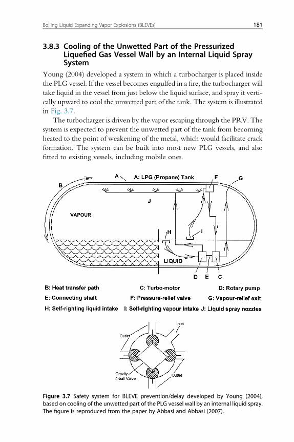
3.8.3 Cooling of the Unwetted Part of the PressurizedLiquefied Gas Vessel Wall by an Internal Liquid SpraySystem
Young (2004) developed a system in which a turbocharger is placed insidethe PLG vessel. If the vessel becomes engulfed in a fire, the turbocharger willtake liquid in the vessel from just below the liquid surface, and spray it verti-cally upward to cool the unwetted part of the tank. The system is illustratedin Fig. 3.7.
The turbocharger is driven by the vapor escaping through the PRV. Thesystem is expected to prevent the unwetted part of the tank from becomingheated to the point of weakening of the metal, which would facilitate crackformation. The system can be built into most new PLG vessels, and alsofitted to existing vessels, including mobile ones.
Figure 3.7 Safety system for BLEVE prevention/delay developed by Young (2004),based on cooling of the unwetted part of the PLG vessel wall by an internal liquid spray.The figure is reproduced from the paper by Abbasi and Abbasi (2007).
Boiling Liquid Expanding Vapor Explosions (BLEVEs) 181
3.8.4 Water DelugeThe thermal load on a PGL vessel engulfed in fire can be substantiallyreduced by water deluge. A layer of flowing water must then be appliedto the vessel as soon as possible. A water layer of sufficient thickness shouldthen totally cover the vessel wall, not least those areas that are directlyengulfed by the flame. A water flow rate of minimum 10e15 L/m2/minis recommended. If the flame is highly turbulent, flow rates even largerthan 25 L/m2/min may be required. If, however, the vessel is beingimpinged by a jet fire, water deluge is less effective.
3.8.5 Rapid Tank DepressurizationIn addition to activating the water deluge system, an effective system forrapid depressurization of the vessel, which bypasses the normal PRV, andcapable of reducing the vessel pressure to half the design pressure within15 min, should be available and activated. The released material should beeliminated in a safe manner, for example by flaring. The depressurizationshould not be too rapid, as it can lead to extremely low temperatures andincreased fragility of the steel.
3.9 REDUCING CONSEQUENCES IF A BLEVE DOESOCCUR
3.9.1 Inherently Safer DesignAs discussed by Shariff et al. (2014), implementation of the inherently
safer plant concept can be a powerful means of reducing the BLEVE risk. Itis then important that the potential consequences of a BLEVE be evaluatedat the preliminary design stage, and adequate design improvements effec-tuated as early as possible. It may then be possible to minimize, or perhapseven eliminate, the risks associated with BLEVEs. However, the inherentlysafer plant concept is not always easy to implement at the preliminarydesign stage at which the technical details of the plant are not in place.Shariff et al. (2014) suggested a new approach to overcome this problem,using a mathematical simulation model. They were then able to assess po-tential BLEVE impacts in terms of overpressures, thermal radiation fluxesand missile hazards. They illustrated the feasibility of their approach byconducting a case study of a BLEVE from a propane storage vessel at theearly design stage.
182 Explosion Hazards in the Process Industries
3.9.2 Establishment and Implementation of Adequate SafetyDistances
If a vessel suffers a BLEVE within only a few minutes after the formation ofthe first crack, little can be done to reduce the damage it would cause. How-ever, even if a BLEVE is delayed by several hours, challenges exist. Greatcare must be taken to make sure that people move to outside the safety dis-tance, both with regard to a potential blast wave, potential missiles, and apotential major fireball. The destructive impact of a delayed BLEVE canbe even more severe than from an immediate one.
Birk (1996) suggested that firefighters should not get closer to a vesselthat could undergo a BLEVE than four fireball radii, but the distance shouldnot be shorter than 90 m. He suggested that a rough estimate of the fireballradius can be obtained by the simple expression
R ¼ 3$m0:33 [3.1]
in which m is the mass of fuel in kg and R is the fireball radius in m.People should be moved to a distance preferably 30 fireball radii away
from vessels that could undergo a BLEVE. The distance would have to beincreased downwind of the vessel. However, as the vessel size increasesbeyond 5 m3 the 30 radii requirement gets too conservative and a require-ment of minimum 15 radii becomes more appropriate.
If the PLG involved in a BLEVE is toxic, eg, chlorine, ammonia, methylisocyanate or phosgene, careful attention has to be paid to its dispersionpattern both in the blast from the BLEVE and in the atmosphere fartheraway.
3.9.3 Preventing “Domino” EffectsThe first concern toward mitigation of the damage caused by a BLEVE is toprevent the initial accident from triggering secondary, higher-order acci-dents. Analyses of BLEVEs that have occurred in the past reveal thatmost of them were not “stand-alone” accidents. Other liquid-containingvessels in the vicinity of a vessel that has BLEVEd can become exposedto heat and/or missiles from the initial event. This may then give rise tofurther BLEVEs. To avoid such “domino” effects, vessels that may causeBLEVEs should be kept sufficiently far away from each other to rendersuch effects unlikely. Mechanical barriers may also be placed around vesselsto limit the impact of outgoing or incoming missiles. This may require
Boiling Liquid Expanding Vapor Explosions (BLEVEs) 183
rather complex design, and careful cost/benefit considerations may beneeded.
3.9.4 Fireball SuppressionIf sufficient quantities of fire suppressant can be released in such a way thatthe suppressant becomes mixed with the flashing fuel at the moment ofvessel failure, the formation of a fireball may be prevented or at least itsintensity may be reduced significantly. Alternatively, the fireball, after itsformation, may be wrapped in a barrier of a suitable fire suppressant.Then, the suppressant would be sucked into the fireball by the very strongprevailing air entrainment flows. As a result, the flame may becomecompletely suppressed, or at least the fireball size would be significantlyreduced. The use of water mist as a fireball suppressant is an obvious possi-bility but the liquid droplets may evaporate completely before the water getssucked into the fireball. This may reduce the suppressing effect.
184 Explosion Hazards in the Process Industries


![MATHEMATICAL MODELLING AND SIMULATION OF HEAT ...eprints.utm.my/id/eprint/1442/1/JT37F[2].pdfvapour cloud explosions, flash fire and BLEVEs. For the determination of heat flux distribution](https://img.pdfslide.us/doc/110x75/613b4e0df8f21c0c8268ecc0/mathematical-modelling-and-simulation-of-heat-2pdf-vapour-cloud-explosions.jpg)