Embed Size (px)
Citation preview
srellatsni roFSU 3002/30 – 6672 2036
Please read these instructions carefully!
Boiler Installation and Maintenance Manual
Condensing Gas Boiler SB615 Series

Impressum
This equipment conforms to the following European and US requirements:
– 90/396/EWG European gas fired guidelines
– Standards: EN 677, EN 303-1, EN 303- 3, DIN 4702-6
– 92/42/EWG European efficiency guidelines
– 73/23/EWG European low voltage guidelines
– 89/336/EWG EMV-European electro-mechanical code guidelines
– 97/23/EG European Pressure vessel guidelines
– ASME Boiler Pressure Code
Conformation regarding conformity with respect to these guidelines can be obtained upon request from Buderus Hydronic Systems.
Technical Changes!
Buderus Hydronic Systems, Inc. reserves the right to make changes due to continued technological and engineering improvements.
Updating Technical Information
Please contact us if you have suggestions for improving this manual or when you have noticed incorrect information.
Manufacturers Address:
Buderus Hydronic Systems, Inc.
50 Wentworth Ave
Londonderry, New Hampshire 03053
www.buderus.net
Document number: 6302 2766
Issue: 03/2003
2
We reserve the right to make any changes due to technical modifications!
Boiler Installation and Maintenance Manual Logano plus SB615 • Issue 03/2003
Buderus Heiztechnik GmbH • http://www.heiztechnik.buderus.de

TABLE OF CONTENTS
3
We reserve the right to make any changes due to technical modifications!
Boiler installation and maintenance manual Logano plus SB615 • Issue 03/2003
Buderus Heiztechnik GmbH • http://www.heiztechnik.buderus.de
1 Regulations and Guidelines . . . . . . . . . . . . . . . . . . . . . . . . . . . . . . . . . . . .4
2 Packaging and Components . . . . . . . . . . . . . . . . . . . . . . . . . . . . . . . . . . . .5
3 Technical Data, Dimensions and Water Connections . . . . . . . . . . . . . . . . .6
4 Boiler Installation . . . . . . . . . . . . . . . . . . . . . . . . . . . . . . . . . . . . . . . . . . . .8
5 Boiler Assembly . . . . . . . . . . . . . . . . . . . . . . . . . . . . . . . . . . . . . . . . . . . . .9
5.1 Installation of Insulation and Jacket Panels . . . . . . . . . . . . . . . . . . . . . . . . . . . .9
5.2 Installation and Wiring of Logamatic Controls (optional) . . . . . . . . . . . . . . . . . . . 13
5.3 Burner Door and Burner Installation . . . . . . . . . . . . . . . . . . . . . . . . . . . . . . . 15
5.4 Additional Jacket Panel Installation . . . . . . . . . . . . . . . . . . . . . . . . . . . . . . . . 16
5.5 Rating Label . . . . . . . . . . . . . . . . . . . . . . . . . . . . . . . . . . . . . . . . . . . . . . 18
5.6 Venting System . . . . . . . . . . . . . . . . . . . . . . . . . . . . . . . . . . . . . . . . . . . . 18
5.7 Condensate Neutralization System and Water Connection Installation . . . . . . . . . . 22
6 Placing the Boiler in Operation . . . . . . . . . . . . . . . . . . . . . . . . . . . . . . . . . 23
7 Maintenance . . . . . . . . . . . . . . . . . . . . . . . . . . . . . . . . . . . . . . . . . . . . . . . 24
7.1 General information . . . . . . . . . . . . . . . . . . . . . . . . . . . . . . . . . . . . . . . . . 24
7.2 Cleaning of the boiler . . . . . . . . . . . . . . . . . . . . . . . . . . . . . . . . . . . . . . . . 24
7.3 Check List . . . . . . . . . . . . . . . . . . . . . . . . . . . . . . . . . . . . . . . . . . . . . . . 26

Regulations and Guidelines1
4
We reserve the right to make any changes due to technical modifications!
Boiler installation and maintenance manual Logano plus SB615 • Issue 03/2003
Buderus Heiztechnik GmbH • http://www.heiztechnik.buderus.de
1 Regulations and Guidelines
The installation must conform to the requirements of the authority having jurisdiction or, in absence of such requirements, to the latest edition of the National Fuel Code, ANSI Z223.1.
The Buderus SB615 boiler is a condensing boiler suitable for firing with natural gas or propane only.
The installation of a low water cut-off and pressure relief valve must be based on local code requirements. Please install these components per manufacturer's instructions and per details on page 22.
Hydrostatic Test
� To avoid build-up of debris inside the heat exchanger of the boiler, it is recommended to install a filter on the boiler return connection(s).
Maximum Temperature and Pressure Ratings
Permissible Fuels:
Logano plus SB615: Natural Gas or L.P Please observe the guidelines of the gas supply company!
WARNING!
DANGER
Explosion danger due to the presence of gas.
� Only a qualified installing contractor may carry out the installation, the initial start-up, the electrical work, maintenance and gas connections.
� Any work on gas components must be carried out by a qualified gas service technician.
NOTICE
Observe the listed boiler output ratings as shown on the boiler rating plate.
Maximum Temperature and Pressure RatingsMaximum Supply Temperature: 210 °F
Allowed System Pressure(Models)
145 and 185 36 psi
240 and 310 36 psi
400, 510 and 640 36 psi
Maximum Time constant:
- Manual Reset High Limit 40 sec
- Adjustable High Limit 40 sec
Table. 1 Maximum Temperature and Pressure Ratings

Packaging and Components 2
5
We reserve the right to make any changes due to technical modifications!
Boiler installation and maintenance manual Logano plus SB615 • Issue 03/2003
Buderus Heiztechnik GmbH • http://www.heiztechnik.buderus.de
2 Packaging and Components
The complete product is shipped in the following components:
– Boiler vessel, packaged on a pallet
– Supply manifold, relief valve and temperature/pres-sure gauge
– Technical documentation, secured to the boiler
– Spare gasket, secured to the boiler
– Boiler jacket panels, insulation and installation components, packaged in a wooden crate
– Electronic control panel, in cardboard box (optional)
– Condensate neutralization package (in cardboard box) (optional)
– Hydronic control package, consisting of aquastats and low water cut-off (when ordered from Buderus)
Above mentioned components may differ slightly based on the particular boiler model.

Technical Data, Dimensions and Water Connections3
3 Technical Data, Dimensions and Water Connections
Fig. 1 Technical Data, Dimensions and Water Connections
H
H1
B
Q
AA
HA
A
L
LK
M
VK
RK1
RK2
AKO
EK/EL
Legend Fig. 1
QAA Vent Pipe Diameter (inside)
AKO Condensate Drain
EK/EL Water Feed/Boiler Drain
H Boiler Height (without Control)
H1Boiler Height with ControlRegelgerät Logamatic R2107 = H + 6 inch
HAA Centerline Height of Vent Connection
RK1 Low Temperature Return Connection
RK2Higher Temperature Return Connection (optional use)
VK Boiler Supply Connection
MSensing Port for Temperature Sensor of Loga-matic control
L Boiler Length with Jacket
LK Boiler Block Length
B Boiler Width with Jacket
6
We reserve the right to make any changes due to technical modifications!
Boiler installation and maintenance manual Logano plus SB615 • Issue 03/2003
Buderus Heiztechnik GmbH • http://www.heiztechnik.buderus.de

Technical Data, Dimensions and Water Connections 3
Boiler Model Unit 145 185 240 310 400 510 640
Input [MBH] 506 644 835 1080 1393 1776 2228
Output [MBH] 484 612 791 1022 1317 1678 2104IBR Net [MBH] 421 532 688 889 1145 1459 1830Thermal Efficiency [%] 95.6 95.0 94.8 94.6 94.5 94.5 94.4Combustion Efficiency [%] 97.1 96.7 96.5 96.4 96.3 96.2 96.2Length L [inch] 68 ¾ 68 ¾ 70 70 75 ¼
Length LK [inch] 60 61 61 66 ¼
Height H [inch] 54 ¼ 55 ½ 63 ½ 69 ¾
Width B [inch] 35 ½ 38 ¼ 38 ¼ 43 ¼
Vent Pipe Diameter (inner)QAA [inch] 6 8 10 12
Vent Conn. Height HAA [inch] 11 ¾ 12 13 14 ½
Weight [Lbs] 1690 1700 1950 2030 2600 2970 3020
Boiler Supply Conn. VK1. Boiler Return RK1
Inch 2 ½ 3 4 4
2. Boiler Return RK2 Inch 2 2 ½ 2 ½ 3
Stack Temperature[°F]1 104 104 115 115 108 111 111
[°F]2 151 151 160 160 155 156 160
Available Breeching Pressure [Inch WC] dependent on burner
Fireside Pressure Drop [Inch WC] .47 .61 .87 .95 1.18 1.40 1.73
Table 2 Technical Data
NOTE
SB615/145 and SB615/185 models are standard supplied with a 7" to 6" Heat Fab stainless stell vent reducer.
Other models require the use of an approved vent starter coupling.
7
We reserve the right to make any changes due to technical modifications!
Boiler installation and maintenance manual Logano plus SB615 • Issue 03/2003
Buderus Heiztechnik GmbH • http://www.heiztechnik.buderus.de

8
We reserve the right to make any changes due to technical modifications!
Boiler installation and maintenance manual Logano plus SB615 • Issue 03/2003
Buderus Heiztechnik GmbH • http://www.heiztechnik.buderus.de
Boiler Installation4
4 Boiler Installation
It is required to have a floor drain available near the boiler.
It is recommended to place the boiler on solid foundation of 2" to 4 " height. Use dimension B and L (Table 3) to size this foundation.
The supporting floor must be level and of sufficient strength.
Observe the indicated side clearances when placing the boiler (Fig. 2 and Table 3). Dimensions in brackets show minimum clearances to combustibles.
Place the boiler horizontally on the supporting foundation (Fig. 3).
Fig. 2 Clearance Dimensions (see Table 3 for details)*) Note burner length dimension
A1
L
A22
)
*)
Bmin32" 1)
8"
16"(4")
Fig. 3 Refer to table 1, see page 6 for legend
VK
RK2
RK1
AKO
EK/EL
M
Recommended and Minimum (in brackets) Clearances in Inches
Boiler model
Distance(Rear)
Distance(Front)
Length Width Width/Height
A1 A21) L B
Doorway Entrance
145 30" (18") 66" (48") 72" 36" 29"/53"
185 30" (18") 66" (48") 72" 36" 29"/53"
240 32" (20") 66" (48") 72" 38" 32"/54"
310 32" (20") 66" (48") 72" 38" 32"/54"
400 36" (24") 70" (50") 72" 38" 32"/62"
510 40" (28") 80" (60") 78" 43" 37"/69"
640 40" (28") 80" (60") 78" 43" 37"/69"
Table 3 Minimum Clearance
1) Please observe the burner length with respect to the front clearance
Boiler Assembly 5
5 Boiler Assembly
5.1 Installation of Insulation and Jacket Panels
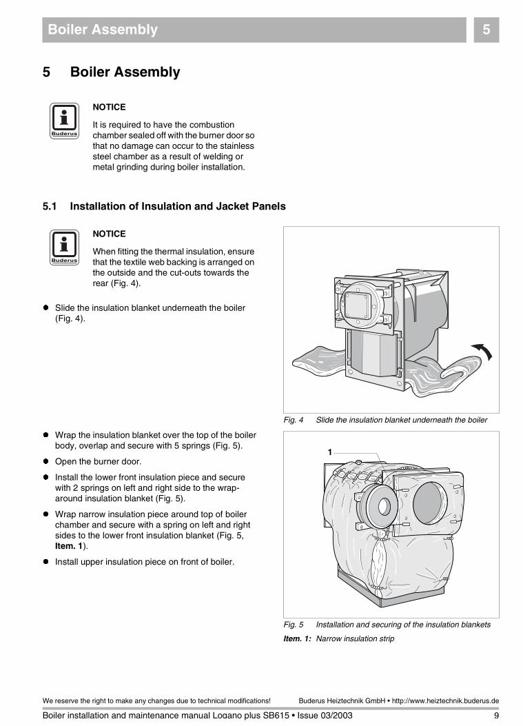
� Slide the insulation blanket underneath the boiler (Fig. 4).
� Wrap the insulation blanket over the top of the boiler body, overlap and secure with 5 springs (Fig. 5).
� Open the burner door.
� Install the lower front insulation piece and secure with 2 springs on left and right side to the wrap-around insulation blanket (Fig. 5).
� Wrap narrow insulation piece around top of boiler chamber and secure with a spring on left and right sides to the lower front insulation blanket (Fig. 5, Item. 1).
� Install upper insulation piece on front of boiler.
NOTICE
It is required to have the combustion chamber sealed off with the burner door so that no damage can occur to the stainless steel chamber as a result of welding or metal grinding during boiler installation.
Fig. 4 Slide the insulation blanket underneath the boiler
NOTICE
When fitting the thermal insulation, ensure that the textile web backing is arranged on the outside and the cut-outs towards the rear (Fig. 4).
Fig. 5 Installation and securing of the insulation blankets
Item. 1: Narrow insulation strip
1
9
We reserve the right to make any changes due to technical modifications!
Boiler installation and maintenance manual Logano plus SB615 • Issue 03/2003
Buderus Heiztechnik GmbH • http://www.heiztechnik.buderus.de

Boiler Assembly5
� Close the burner door and secure evenly with the furnished burner door bolts.
� Place the rear insulation blanket according to the cut-outs and secure with 2 springs on left and right sides to the wrap-around blanket (Fig. 6).
� Secure front cross bracket (wider sections pointing down) at the holes to the threaded studs and secure in place with nuts (Fig. 7).
� Secure rear cross bracket (wider sections pointing down) at the holes to the threaded studs and secure with nuts (Fig. 7).
NOTICE
Observe the cut-outs for burner door hinges and burner door bolts!
Fig. 6 Securing the rear insulation blanket
Fig. 7 Installation of front and rear cross brackets
NOTICE
The edged surface of the cross brackets must point outward and both brackets must be placed horizontally (Fig. 7).
10
We reserve the right to make any changes due to technical modifications!
Boiler installation and maintenance manual Logano plus SB615 • Issue 03/2003
Buderus Heiztechnik GmbH • http://www.heiztechnik.buderus.de

Boiler Assembly 5
� Install top side rails with the U profile in the knock-out of the front and rear cross bracket. Secure with a screw through the round hole in the front, and with a screw through the long slot in the back to the cross brackets (Fig. 8).
� Insert the side jacket panels into the narrow edge of bottom rail (Fig. 9).
� Slightly lift up the top side jacket panels and hang over the edge of the side rails (Fig. 10).
� Push the edges of the insulation blankets behind the side panels (Fig. 10).
� Secure strain relief for the burner cable with two studs into the holes on the left or right side jacket pa-nels. Allow enough length for burner cable, place ca-ble in strain relief, close relief clip and secure strain relief with two screws (Fig. 10).
Fig. 8 Installation and securing of top side rails
Fig. 9 Installation of side jacket panels
NOTICE
The knock-out section of the side panel edge must be oriented towards the middle of the boiler.
Fig. 10 Hanging of side panels and securing of burner cable.
11
We reserve the right to make any changes due to technical modifications!
Boiler installation and maintenance manual Logano plus SB615 • Issue 03/2003
Buderus Heiztechnik GmbH • http://www.heiztechnik.buderus.de

Boiler Assembly5
� Secure lower rear panel with 5 screws to the side panels (Models /145 through /310) (Fig. 11).
� Secure upper rear panel with 4 screws to the side panels (Fig. 11).
� Secure 1 or 2 cable raceways to the upper rear panel (Fig. 11).
� Secure rear panel with four screws on each side to the side panels (Models /400 through /640) (Fig. 12).
� Secure 1 or 2 cable raceways to the upper rear panel (Fig. 12).
Fig. 11 Securing rear panels (Models /145 through /310)
Item. 1: Lower rear panel
Item. 2: Upper rear panel
Item. 3: Cable raceway
3
2
1
3
NOTICE
The rear panel consist of 2 pieces for models /145 through /310 (Fig. 11). Rear panel for models /400 through /640 is a single piece (Fig. 12).
NOTICE
Top screws must be secured to the rear cross bracket!
Fig. 12 Securing single rear panel (Models /400 through /640)
Item. 1: Rear panel
Item. 2: Cable raceway
2
1
2
NOTICE
Top screws must be secured to the rear cross bracket!
12
We reserve the right to make any changes due to technical modifications!
Boiler installation and maintenance manual Logano plus SB615 • Issue 03/2003
Buderus Heiztechnik GmbH • http://www.heiztechnik.buderus.de

Boiler Assembly 5
� Place front top cover on top of side jacket panels and slide forward, until tabs engage into the slots on left and right side (Fig. 13).
� Secure front top cover with two screws to the side jacket panels (Fig. 13).
5.2 Installation and Wiring of Logamatic Controls (optional)
Align the four tabs of the control with the four holes in the front top cover.
� Remove the two screws from the control housing (Fig. 14, Item. 1). Remove top cover.
� Guide capillaries through the cutaway in the front top cover and uncoil desired length. Do not kink capillaries
� Place the control on top of the front top cover, so that the protruding tabs engage into the oval openings. Slide the control panel forward, then rotate slightly back to engage both plastic tabs on the right and left side.
Fig. 13 Engaging and securing front top cover
Fig. 14 Installation of Logamatic control
Item. 1: Screws
Item. 2: Top housing of the control panel
Item. 3: Screws
2
3
1
13
We reserve the right to make any changes due to technical modifications!
Boiler installation and maintenance manual Logano plus SB615 • Issue 03/2003
Buderus Heiztechnik GmbH • http://www.heiztechnik.buderus.de

Boiler Assembly5
� Fasten the control to the boiler jacket top cover using the two screws as shown (Fig. 14, Item. 3).
� Wire the control per furnished schematics.
� Install electrical wiring using the plastic clips and secure wiring by latching in the lever of the plastic tabs (Fig. 15, Item. 1).
� Install the top housing of the control and secure with two furnished screws (Fig. 14, Item. 1.).
� Route the capillaries and electronic sensor to the immersion well supplied with the control. Install Logamatic well into rear boiler tapping.
Fig. 15 White strain reliefs
Item. 1: Plastic clip
Item. 2: Control panel rear side
NOTICE
Please observe careful installation of capillary tubes and electrical wiring
Please observe and install all electrical wiring per local code!
Fig. 16 Install sensor bundle into immersion well
14
We reserve the right to make any changes due to technical modifications!
Boiler installation and maintenance manual Logano plus SB615 • Issue 03/2003
Buderus Heiztechnik GmbH • http://www.heiztechnik.buderus.de

Boiler Assembly 5
� Carefully slide the plastic holding spiral from the sensor bundle as this package is pushed into the well (Fig. 17, Item. 2).
5.3 Burner Door and Burner Installation
The burner door can be installed to swing to the left or right.
� Remove the hinging bolts and washers from the hinges by moving them upward (Fig. 18, Item. 1).
� Install the washers and hinging bolts on the opposite side (Fig. 18, Item. 2). Make sure to install the washers!
Fig. 17 Insert the sensor bundle into well
Item. 1: Tension wafer
Item. 2: Plastic spiral
Item. 3: Locking clip
Item. 4: Immersion well
2
1
3
4
NOTICE
To ensure proper contact between immersion well (Fig. 17, Item. 4) and sensor/capillary surfaces, it is important to install the tension wafer plate (Fig. 17, Item. 1).
NOTICE
The swing direction of the burner door can only be changed when the door is fully closed and bolted down.
Fig. 18 Changing the swing direction of the burner door
Item. 1: Hinging bolt
Item. 2: Washers
1
1
2
2
15
We reserve the right to make any changes due to technical modifications!
Boiler installation and maintenance manual Logano plus SB615 • Issue 03/2003
Buderus Heiztechnik GmbH • http://www.heiztechnik.buderus.de

Boiler Assembly5
5.4 Additional Jacket Panel Installation
Models /145 to /4004 top cover panels
Models /510 to /6405 top cover panels
� Place top cover panels loose on top of the right and left hand side panels (Fig. 20).
Fig. 19 Blast tube clearance space
Item. 1: Clearance between blast tube and burner door insulation
1
7 ¼"NOTICE
Observe burner manufacturers recommendations regarding the burner installation procedures!
A pre-cut burner plate will be supplied by Buderus Hydronic Systems, Inc. if the burner is purchased from Buderus. If not, a properly cut burner plate must be fabricated.
The space between burner blast tube and burner door insulation must be closed off with suitable material (Fig. 19, Item. 1)!
Use blast tube refractory material supplied with the boiler. Cut material to proper size.
Fig. 20 Placement of top cover panels
Item. 1: Cut-out location
1
NOTICE
The second top cover panel has, starting with model /400, a cut-out (Fig. 20, Item. 1). The other top cover panels are the same and are to be oriented with the edge forward.
16
We reserve the right to make any changes due to technical modifications!
Boiler installation and maintenance manual Logano plus SB615 • Issue 03/2003
Buderus Heiztechnik GmbH • http://www.heiztechnik.buderus.de

Boiler Assembly 5
� Insert the tabs of the lower front cross bracket into the slots of the side jacket panels and secure the cross bracket with 2 screws to the front of the boiler (Fig. 21).
� Hang the lower front panel with the four tabs (Fig. 22, Item. 1) into the slots of the side jacket panels.
� Latch the tabs of the top front panel into the side jacket panel slots and rest the top part into the top front cover (Fig. 22).
� Hang the top and bottom front cover pieces at the tabs on the front panels (Fig. 22).
� Affix the name plate cover (Fig. 22, Item. 2) on the front panel.
Fig. 21 Securing the lower front cross bracket
Fig. 22 Upper and lower front jacket panels
Item. 1: Tabs
Item. 2: Name plate cover
1
2
17
We reserve the right to make any changes due to technical modifications!
Boiler installation and maintenance manual Logano plus SB615 • Issue 03/2003
Buderus Heiztechnik GmbH • http://www.heiztechnik.buderus.de

Boiler Assembly5
5.5 Rating Label
� Secure the rating label to the left or right side of the boiler based on local requirements (Fig. 23, Item. 1).
5.6 Venting System
� The resulting combustion products must be transported through a chimney system to the outside.
� It is required to use venting systems approved for use with condensing, gas-fired equipment.
� Prior to placing the boiler in operation, it is required to verify compatibility between boiler and venting system.
� Check the venting system for air tightness!
� Install the venting system per manufacturer's instructions.
Fig. 23 Securing the rating label
Item. 1: Rating label
1
18
We reserve the right to make any changes due to technical modifications!
Boiler installation and maintenance manual Logano plus SB615 • Issue 03/2003
Buderus Heiztechnik GmbH • http://www.heiztechnik.buderus.de

Boiler Assembly5
SB Boiler Venting Requirements
The SB Boiler is a category II or IV appliance and the exhaust vent materials must be UL listed for use with a category IV appliance: operating temperatures of up to 240° F, positive pressure, condensing flue gas service. Currently, UL Listed vents of AL29-4C Stainless steel and/or CPVC must be used with the SB Boiler. Proper clearances to combustibles must be maintained per UL and vent manufacturer.
UL, NFPA 211 and NFPA 54 (National Flue Gas Code ANSI Z223.1) guidelines are often the basis for state and local codes. Buderus Hydronic Systems recommendations follow the guidelines of these recognized agencies unless there codes applicable to the installation site that are more stringent. The venting and combustion air systems must meet all applicable code requirements.
Code Required Vent Terminations:
Horizontal Terminations:
� Vent terminations should be at least 4 feet below, 1 foot above or 4 feet horizontally from any window, door or gravity air inlet of a building.
� The termination shall be at least 3 feet away from any other building opening, gas utility meter, service regulator or the like.
� The termination shall be at least 6 feet away from the combustion air intake of any other appliance.
� The bottom of the vent terminal should be at least 12 inches above both finished grade and any snow accumulation point.
� Vent should not terminate over public walkways or over an area where condensate or vapor could create a nuisance or be detrimental to the operation of regulators, meters and other equipment.
� Discharges should not be in wind-blocked areas, corners, or directly behind vegetation.
Vertical Terminations:
� Roof penetrations should follow all applicable codes and the vent manufacturer's instructions. The vent should never be installed at less than the required clearances to combustible materials per UL, NFPA, and local codes. "Double-wall or thimble" assemblies are required when penetrating combustible walls and roofs.
� Vertical discharges should extend at least 2 feet above the roof through properly flashed penetrations and at least 2 feet above anything within a 10 foot
horizontal diameter. Discharges that extend more than 2 feet above the roof must be laterally supported.
� If the vent system is to be connected to an existing stack, the stack must be UL Listed for Category II or IV appliances (capable of 240°F, positive pressure and condensing flue gas operation).
� Masonry stacks must be lined and the vent penetration must terminate flush with and be sealed to this liner. Vents may enter the stack through the bottom or side.
� SB Boilers vent systems must not be interconnected to any other venting system; The SB Boiler is designed to maintain its own vent system.
� The exhaust vent must be pitched up toward the termination a minimum of ¼" in. per foot of length. Condensate must flow back to the SB Boiler freely, without accumulating in the vent.
19
We reserve the right to make any changes due to technical modifications!
Boiler installation and maintenance manual Logano plus SB615 • Ausgabe 03/2003
Buderus Heiztechnik GmbH • http://www.heiztechnik.buderus.de

Boiler Assembly5
Combustion Air from outside the building
If outside combustion air is required, the room shall have two permanent louvered openings to the outdoors. Each opening must have a minimum free area of 1 square inch for each 4,000 Btu/hr of total input rating of all fuel burning equipment in the space.
When the air is supplied to the room via ducts, two ducts must be used. Vertical ducts and openings must have a minimum free area of 1 square inch for each 4,000 Btuh of the total input rating of all fuel burning equipment in the space. Horizontal ducts and openings must have a minimum free area of 1 square inch for each 2,000 Btuh of the total input rating of all fuel burning equipment in the space.
The free area of the openings must be taken into account restrictions from the louvers and screens. The louver manufacturer should be consulted for the percentage of free area available. When free area is not known, metal louvers typically have 60 - 70% of free area, wooden louvers have between 20 - 25% of free area. Louvers should be in a fixed position or interlocked with equipment so that they open automatically during equipment operation. The combustion air damper opening shall be located as follows: top louver shall began within 12" of the ceiling and the bottom louver within 12" of the floor as prescribed in NFPA 54.
Combustion Air from an adjacent room
Where combustion air is to be used from within the building, air must be provided into the equipment room through two permanent openings into the interior building. Each opening must have a minimum free area of 1 square inch for each 1,000 Btuh of the total input rating of all fuel burning equipment in the space. The louvers shall be located as follows: top louver shall start within 12" of the ceiling and the bottom louver within 12" of the floor as prescribed in NFPA 54.
20
We reserve the right to make any changes due to technical modifications!
Boiler installation and maintenance manual Logano plus SB615 • Issue 03/2003
Buderus Heiztechnik GmbH • http://www.heiztechnik.buderus.de
Boiler Assembly5
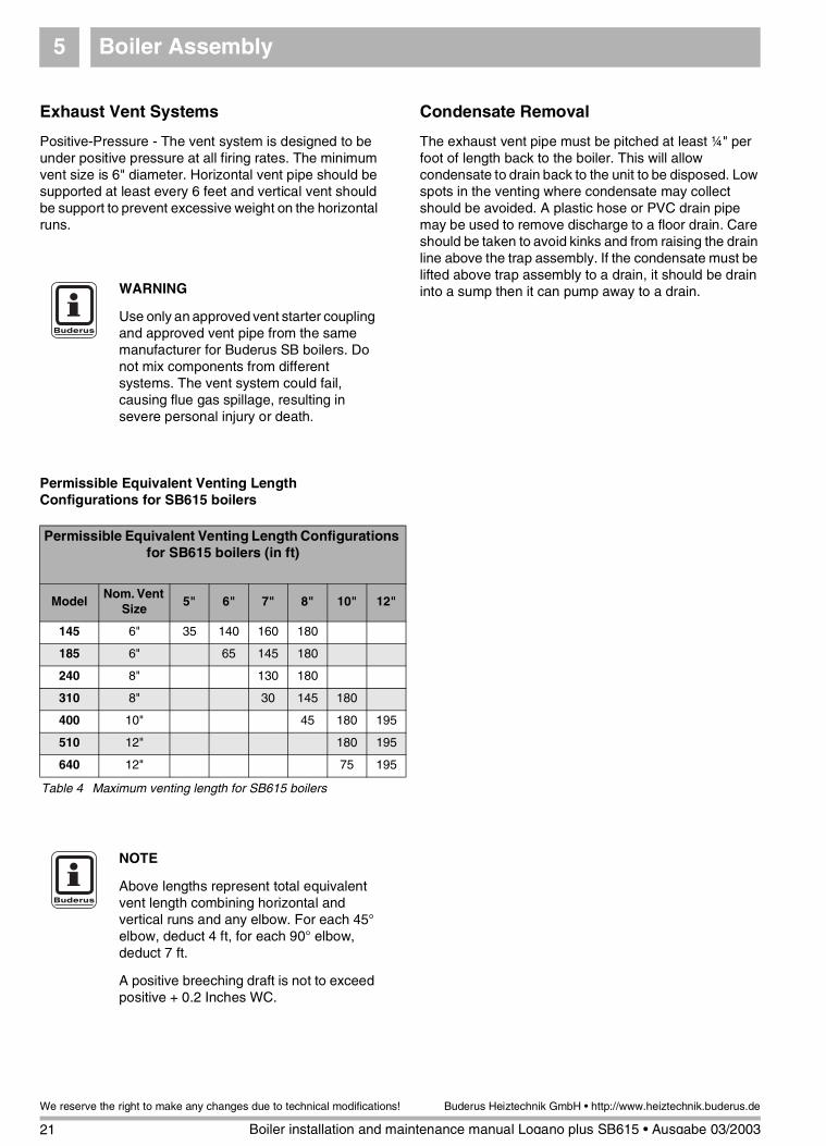
Exhaust Vent Systems
Positive-Pressure - The vent system is designed to be under positive pressure at all firing rates. The minimum vent size is 6" diameter. Horizontal vent pipe should be supported at least every 6 feet and vertical vent should be support to prevent excessive weight on the horizontal runs.
Permissible Equivalent Venting Length Configurations for SB615 boilers
Condensate Removal
The exhaust vent pipe must be pitched at least ¼" per foot of length back to the boiler. This will allow condensate to drain back to the unit to be disposed. Low spots in the venting where condensate may collect should be avoided. A plastic hose or PVC drain pipe may be used to remove discharge to a floor drain. Care should be taken to avoid kinks and from raising the drain line above the trap assembly. If the condensate must be lifted above trap assembly to a drain, it should be drain into a sump then it can pump away to a drain.WARNING
Use only an approved vent starter coupling and approved vent pipe from the same manufacturer for Buderus SB boilers. Do not mix components from different systems. The vent system could fail, causing flue gas spillage, resulting in severe personal injury or death.
Permissible Equivalent Venting Length Configurations for SB615 boilers (in ft)
ModelNom. Vent
Size5" 6" 7" 8" 10" 12"
145 6" 35 140 160 180
185 6" 65 145 180
240 8" 130 180
310 8" 30 145 180
400 10" 45 180 195
510 12" 180 195
640 12" 75 195
Table 4 Maximum venting length for SB615 boilers
NOTE
Above lengths represent total equivalent vent length combining horizontal and vertical runs and any elbow. For each 45° elbow, deduct 4 ft, for each 90° elbow, deduct 7 ft.
A positive breeching draft is not to exceed positive + 0.2 Inches WC.
21
We reserve the right to make any changes due to technical modifications!
Boiler installation and maintenance manual Logano plus SB615 • Ausgabe 03/2003
Buderus Heiztechnik GmbH • http://www.heiztechnik.buderus.de

Boiler Assembly5
5.7 Condensate Neutralization System and Water Connection Installation
If a condensate neutralization system is installed, please follow its installation instructions (Available as an accessory).
� Secure a hose to the condensate drain with a clamp (Fig. 24, Item. 2).
� Secure finished supply manifold and gasket to upper water connection.
� Install furnished relief valve in supply manifold and pipe discharge full port to nearby floor drain.
� Install low water cut-off and Honeywell aquastat(s) in available 3/4" manifold tappings.
� Install pressure and temperature gauge in 1/2" tap-ping.
� Plug any unused tappings.
� Refer to section 5.2 when installing Logamatic control. Plug sensor port M (Fig. 16 page 14) with 3/4" plug when not using a Logamatic control.
Fig. 24 Installation of neutralization system
Item. 1: Clean-out opening
Item. 2: Condensate drain connection
1
2
NOTICE
Typically the condensate will drain back to the boiler from the venting system. If this is not feasible, use only a stainless steel or plastic tee with a drain connection in the venting system.
NOTICE
Lower return connection RK1 (Fig. 1, page 6) must always be used. Connect coldest return zone (s) to RK1. Connect higher temperature return zone (s) to RK2 if called for by engineering firm. If RK2 connection is not used, close off with a blanking flange.
22
We reserve the right to make any changes due to technical modifications!
Boiler installation and maintenance manual Logano plus SB615 • Issue 03/2003
Buderus Heiztechnik GmbH • http://www.heiztechnik.buderus.de

Placing the Boiler in Operation 6
23
We reserve the right to make any changes due to technical modifications!
Boiler installation and maintenance manual Logano plus SB615 • Issue 03/2003
Buderus Heiztechnik GmbH • http://www.heiztechnik.buderus.de
6 Placing the Boiler in Operation
WARNING!
DANGER
due to combustion products.
� Prior to placing the boiler in operation, put 3 or 4 gallons of water in the clean-out opening or combustion chamber to fill the drain in the condensate drain line.
CAREFUL!
BOILER DAMAGE
due to corrosion and debris build-up.
� Flush the entire heating system prior to firing the boiler. To avoid corrosion and debris build-up on the water side of the boiler. It is required to test the fill and make-up water per Instructions for Water Preparation for Boiler.
NOTICE
Observe the installation instructions for the neutralization system!
Follow the instructions supplied with boiler, burner, controls and low water cut-off components during the start-up of the system.
Make the end user familiar with the function and operation of the entire system and sign over the technical documentation.
It is recommended to instruct the end user regarding maintenance requirements and procedures. An annual service contract is recommended.

Maintenance 7
7 Maintenance
7.1 General information 7.2 Cleaning of the boiler
WARNING!
DANGER
due to unauthorized service work.
� Maintenance work on gas components can only be carried out by a gas certified service company.
NOTICE
The end user or operator is required to have regular scheduled maintenance performed. An annual maintenance procedure on the entire system is required.
We recommend an annual service contract for the maintenance.
The factory required maintenance steps are outlined in the check list (see section 7.3 „Check List“).
Follow the burner manufacturer's instructions regarding burner maintenance!
WARNING!
DANGER
due to current carrying wires.
� Prior to maintenance shut down the electrical power supply and pad lock!
CAREFUL!
BOILER DAMAGE
due to incorrect boiler brushes.
� Use only brushes made available through Buderus Hydronic Systems, Inc..
NOTICE
A high pressure washer is recommended for a wet cleaning of the heat exchanger.
Boiler debris should not be sent through the neutralization system.
Check to make sure the condensate drain does not get plugged (Fig. 24, page 22).
24
We reserve the right to make any changes due to technical modifications!
Boiler installation and maintenance manual Logano plus SB615 • Issue 03/2003
Buderus Heiztechnik GmbH • http://www.heiztechnik.buderus.de

Maintenance 7
� Check and possibly clean the flue collector and condensate drain through the rear clean-out opening (Fig. 24, page 22).
� Remove upper and lower front panel (Fig. 25).
� Remove insulation blanket (Fig. 25).
� Remove nuts from holding bracket and remove front reversing cover (Fig. 26).
� Remove hexhead nuts from burner door and open burner door (Fig. 26).
� Clean and brush out combustion chamber and surfaces.
� Brush out secondary flue passages (Fig. 27).
� Remove any debris with a vacuum cleaner from the surfaces.
� Check for air leaks around the burner door and other openings. Replace gaskets where necessary.
Follow the instructions of the power cleaning equipment!
Keep moisture away from all electrical components!
� After cleaning, close burner door and secure.
� Reinstall reversing cover and secure with holding bracket (Fig. 26).
� Secure insulation blanket with spring clips.
� Install upper and lower boiler front panels (Fig. 25).
� Put the system back in operation.
Fig. 25 Removal of front panels and insulation blanketsNOTICE
When cleaning the second and third passages, make sure that the brush has fully traveled the length of the tubes to the rear of the boiler and is sticking outside of the tube before pulling the brush forward.
Fig. 26 Remove the reversing cover and open the burner door
Fig. 27 Brushing of fire tubes
25
We reserve the right to make any changes due to technical modifications!
Boiler installation and maintenance manual Logano plus SB615 • Issue 03/2003
Buderus Heiztechnik GmbH • http://www.heiztechnik.buderus.de

Maintenance7
7.3 Check List
� Check off the different maintenance steps, place an "x" in the corresponding box and list date and service company name below.
� Follow recommended time frame for boiler and burner maintenance work.
Heating System 01 02 03 04 05 06 07 08
1 Disconnect electrical supply to system
2 Shut off gas supply
3 Disconnect gas supply from burner
4 Remove front jacket panels, open burner door (Fig. 25, page 25)
5 Remove reversing cover (Fig. 26, page 25)
6 Remove condensate drain hose from neutralization system (Fig. 24, page 22)
7 Check and clean combustion chamber
8 Check and clean out fire tube passages
9 Flush condensate drain connection at boiler (Fig. 24, page 22)
10 Check and clean flue collector
11 Check burner door gasket, replace if necessary
12 Check silicone gasket on reversing cover, replace if necessary
13 Reattach condensate drain hose
14 Close off the reversing cover, bolt down and assemble jacket panels
15 Pour 3 gals. of water into the combustion chamber
16 Pour 3 gals. of water into the combustion chamber
17 Reattach the gasline to the burner
18 Check gas components for leaks and correct if necessary
19 Check venting system for leaks, repair when needed
20 Check operation of all safety controls
21 Check operation of all operating controls
22 Bring the system back into regular operation
23
24
Follow the instructions for the neutralization system regarding maintenance
Service Company 01
Date:
Service Company 02
Date:
Service Company 03
Date:
Service Company 04
Date:
Service Company 05
Date:
Service Company 06
Date:
Service Company 07
Date:
Service Company 08
Date:
26
We reserve the right to make any changes due to technical modifications!
Boiler installation and maintenance manual Logano plus SB615 • Issue 03/2003
Buderus Heiztechnik GmbH • http://www.heiztechnik.buderus.de

Notes
27
We reserve the right to make any changes due to technical modifications!
Boiler installation and maintenance manual Logano plus SB615 • Issue 03/2003
Buderus Heiztechnik GmbH • http://www.heiztechnik.buderus.de

BBT North America Corporation50 Wentworth Avenue
Londonderry, NH 03053Tel: 603-552-1100 ● Fax: 603-584-1681
www.buderus.net
BBT North America Corporation reserves the right to make changes without notice due to continuing engineering and technological advances.
Heating Contractor:
PRODUCTS MANUFACTURED BY
BBT Thermotechnik GmbH35573 Wetzlar
www.buderus.de