Embed Size (px)
Citation preview
Installation and maintenance instructions
Oil- and gas-fired boilers
For heating engineers
Please read carefully prior to installation and maintenance.
Logano GE515
6 72
0 61
7 71
8 - 0
7/20
08 G
B
Preamble
Logano GE515 - We reserve the right to make any changes due to technical modifications.2
Regarding these instructions
These installation and maintenance instructions contain important information for the safe and correct installation, initial start-up and maintenance of the Logano GE515 oil- and gas-fired special boiler.
These installation and maintenance instructions are designed for specialists, who, due to their vocational training, are knowledgeable and experienced in handling heating systems and oil/gas installations.
The Logano GE515 oil- and gas-fired special boiler may be supplied as one of two versions (in loose sections or pre-assembled).
These installation and maintenance instructions explain the installation and maintenance on the example of boi-lers supplied as loose sections and as pre-assembled blocks.
This device meets all basic requirements of relevant European standards and guidelines.
Its conformity has been verified. All associated documents and the original of the Declaration of Conformity are available from the manufacturer.
Subject to technical modifications.
Constant development may lead to minor deviations in the illustrations, functional steps and specifications described/shown.
Updating your documentation
Please let us know if you would like to make suggestions to improve our documentation or if you have noticed any errors.
Index
1 General . . . . . . . . . . . . . . . . . . . . . . . . . . . . . . . . . . . . . . . . . . . . . . . . . . . .5
2 Safety . . . . . . . . . . . . . . . . . . . . . . . . . . . . . . . . . . . . . . . . . . . . . . . . . . . . .6
2.1 Correct use . . . . . . . . . . . . . . . . . . . . . . . . . . . . . . . . . . . . . . . . . . . . . . .62.2 Notes structure . . . . . . . . . . . . . . . . . . . . . . . . . . . . . . . . . . . . . . . . . . . . .62.3 Please observe these notes . . . . . . . . . . . . . . . . . . . . . . . . . . . . . . . . . . . . .7
3 Product description . . . . . . . . . . . . . . . . . . . . . . . . . . . . . . . . . . . . . . . . . .8
3.1 Operating conditions for Buderus G and GE cast iron boilers . . . . . . . . . . . . . . . . .93.2 Operating conditions GE 515 . . . . . . . . . . . . . . . . . . . . . . . . . . . . . . . . . . . .9
4 Specification . . . . . . . . . . . . . . . . . . . . . . . . . . . . . . . . . . . . . . . . . . . . . . . 10
5 Standard delivery . . . . . . . . . . . . . . . . . . . . . . . . . . . . . . . . . . . . . . . . . . . 12
5.1 Logano GE515 – delivery as ready assembled unit . . . . . . . . . . . . . . . . . . . . . . 125.2 Logano GE515 – delivery in sections . . . . . . . . . . . . . . . . . . . . . . . . . . . . . . 12
6 Boiler handling . . . . . . . . . . . . . . . . . . . . . . . . . . . . . . . . . . . . . . . . . . . . . 13
7 Boiler positioning . . . . . . . . . . . . . . . . . . . . . . . . . . . . . . . . . . . . . . . . . . . 14
7.1 Tools and accessories . . . . . . . . . . . . . . . . . . . . . . . . . . . . . . . . . . . . . . . . 147.2 Recommended wall clearances . . . . . . . . . . . . . . . . . . . . . . . . . . . . . . . . . . 167.3 Positioning the boiler on a sub-structure or on foundations . . . . . . . . . . . . . . . . . 17
8 Boiler block assembly. . . . . . . . . . . . . . . . . . . . . . . . . . . . . . . . . . . . . . . . 18
8.1 Arrangement of boiler sections within the boiler block . . . . . . . . . . . . . . . . . . . . 198.2 Joining the boiler block assembly . . . . . . . . . . . . . . . . . . . . . . . . . . . . . . . . . 198.3 Positioning the boiler block – for pre-assembled deliveries . . . . . . . . . . . . . . . . . 268.4 Sliding the feed pipe into place (carton of installation components) . . . . . . . . . . . . 278.5 Seal-in the sensor well . . . . . . . . . . . . . . . . . . . . . . . . . . . . . . . . . . . . . . . 278.6 Leak test . . . . . . . . . . . . . . . . . . . . . . . . . . . . . . . . . . . . . . . . . . . . . . . . 288.7 Boiler water connections . . . . . . . . . . . . . . . . . . . . . . . . . . . . . . . . . . . . . . 298.8 Installing boiler fittings and the burner door . . . . . . . . . . . . . . . . . . . . . . . . . . 318.9 Installing the boiler shell. . . . . . . . . . . . . . . . . . . . . . . . . . . . . . . . . . . . . . . 34
9 Boiler flue connection . . . . . . . . . . . . . . . . . . . . . . . . . . . . . . . . . . . . . . . . 44
9.1 Fit the flue pipe sealing collar (accessory) . . . . . . . . . . . . . . . . . . . . . . . . . . . 449.2 Fitting the flue gas temperature sensor (accessory) . . . . . . . . . . . . . . . . . . . . . 45
10 Installing the control device . . . . . . . . . . . . . . . . . . . . . . . . . . . . . . . . . . . 46
10.1 Installing the control device. . . . . . . . . . . . . . . . . . . . . . . . . . . . . . . . . . . . . 4610.2 Installing the temperature sensor set and burner cable . . . . . . . . . . . . . . . . . . . 47
11 Burner installation . . . . . . . . . . . . . . . . . . . . . . . . . . . . . . . . . . . . . . . . . . 49
12 System start-up. . . . . . . . . . . . . . . . . . . . . . . . . . . . . . . . . . . . . . . . . . . . . 50
12.1 Filling the system . . . . . . . . . . . . . . . . . . . . . . . . . . . . . . . . . . . . . . . . . . . 5012.2 Making the system operational . . . . . . . . . . . . . . . . . . . . . . . . . . . . . . . . . . 51
Logano GE515 - We reserve the right to make any changes due to technical modifications. 3
Index
12.3 Commissioning the control device . . . . . . . . . . . . . . . . . . . . . . . . . . . . . . . . 5112.4 Start up the burner . . . . . . . . . . . . . . . . . . . . . . . . . . . . . . . . . . . . . . . . . 5112.5 Raising the flue gas temperature . . . . . . . . . . . . . . . . . . . . . . . . . . . . . . . . 5212.6 Commissioning report . . . . . . . . . . . . . . . . . . . . . . . . . . . . . . . . . . . . . . . 54
13 System shutdown . . . . . . . . . . . . . . . . . . . . . . . . . . . . . . . . . . . . . . . . . . 55
13.1 Shutting down the system via the control device . . . . . . . . . . . . . . . . . . . . . . . 5513.2 Shutting down the system in an emergency . . . . . . . . . . . . . . . . . . . . . . . . . 55
14 System inspection and maintenance. . . . . . . . . . . . . . . . . . . . . . . . . . . . 56
14.1 General notes . . . . . . . . . . . . . . . . . . . . . . . . . . . . . . . . . . . . . . . . . . . . 5614.2 Why is regular maintenance important? . . . . . . . . . . . . . . . . . . . . . . . . . . . . 5614.3 Cleaning the boiler with cleaning brushes . . . . . . . . . . . . . . . . . . . . . . . . . . . 5714.4 Wet-cleaning the boiler . . . . . . . . . . . . . . . . . . . . . . . . . . . . . . . . . . . . . . 6014.5 Checking the system water pressure . . . . . . . . . . . . . . . . . . . . . . . . . . . . . . 6114.6 Inspection and maintenance reports . . . . . . . . . . . . . . . . . . . . . . . . . . . . . . 63
15 Correcting burner faults . . . . . . . . . . . . . . . . . . . . . . . . . . . . . . . . . . . . . 65
16 Index . . . . . . . . . . . . . . . . . . . . . . . . . . . . . . . . . . . . . . . . . . . . . . . . . . . . 66
Logano GE515 - We reserve the right to make any changes due to technical modifications.4
General 1
Logano GE515 - We reserve the right to make any changes due to technical modifications. 5
1 General
USER NOTE
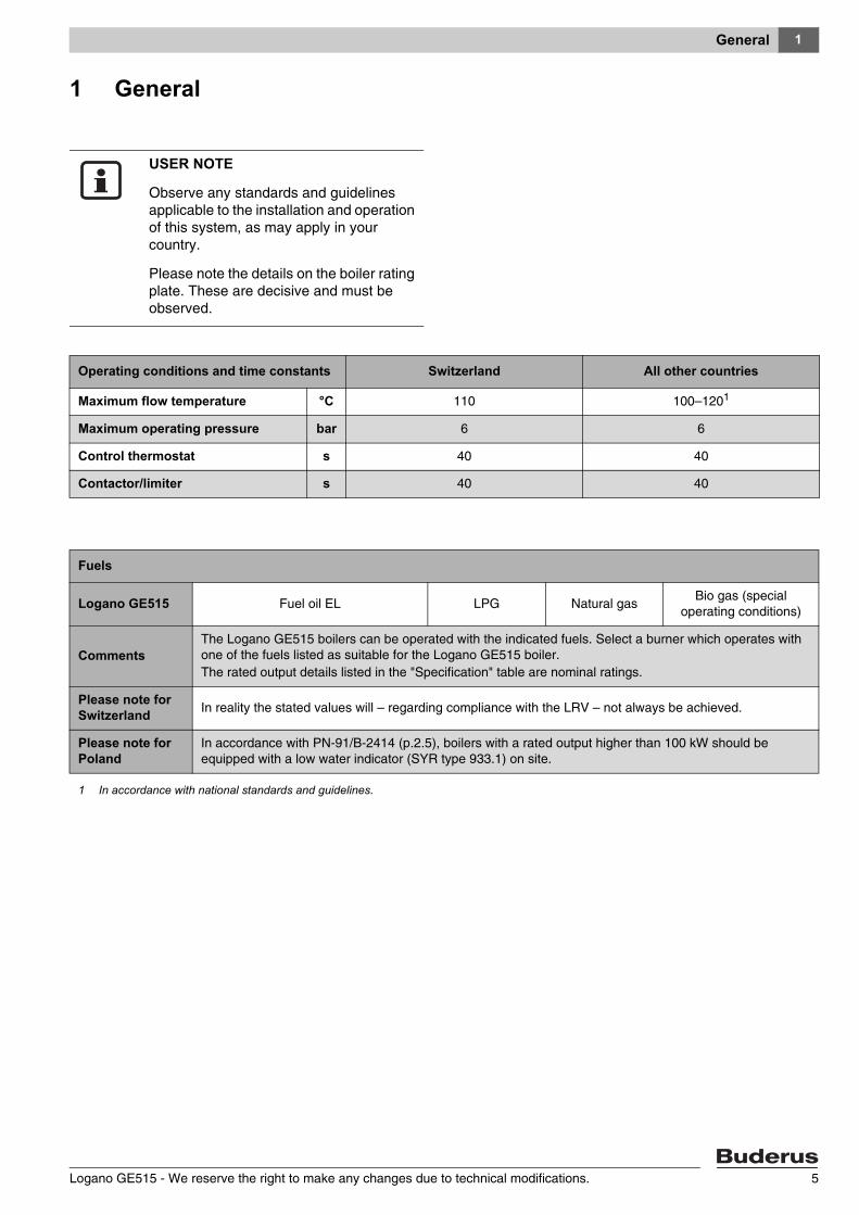
Observe any standards and guidelines applicable to the installation and operation of this system, as may apply in your country.
Please note the details on the boiler rating plate. These are decisive and must be observed.
Operating conditions and time constants Switzerland All other countries
Maximum flow temperature °C 110 100–1201
Maximum operating pressure bar 6 6
Control thermostat s 40 40
Contactor/limiter s 40 40
Fuels
Logano GE515 Fuel oil EL LPG Natural gasBio gas (special
operating conditions)
CommentsThe Logano GE515 boilers can be operated with the indicated fuels. Select a burner which operates with one of the fuels listed as suitable for the Logano GE515 boiler.The rated output details listed in the "Specification" table are nominal ratings.
Please note for Switzerland In reality the stated values will – regarding compliance with the LRV – not always be achieved.
Please note for Poland
In accordance with PN-91/B-2414 (p.2.5), boilers with a rated output higher than 100 kW should be equipped with a low water indicator (SYR type 933.1) on site.
1 In accordance with national standards and guidelines.
Safety2
2 Safety
For your own safety, observe these safety instructions.
2.1 Correct use
The Logano GE515 oil- and gas-fired special boiler was designed for the heating of central heating water. You may use any type-tested oil-fired or gas-fired burners acc. to EN 267 or EN 676 provided their operating range correlates with the boiler specification.
These boilers are operated with the 4000 series control systems.
2.2 Notes structure
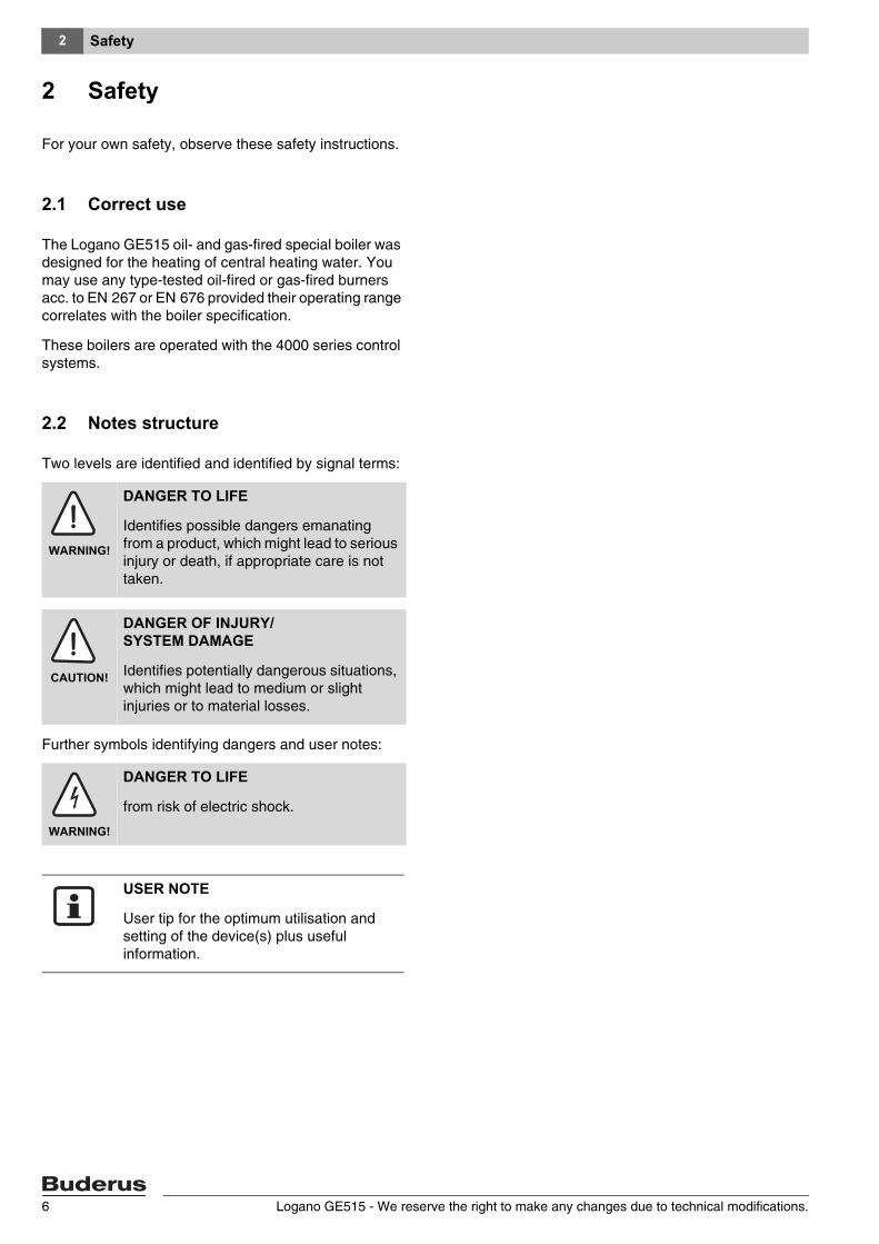
Two levels are identified and identified by signal terms:
Further symbols identifying dangers and user notes:
WARNING!
DANGER TO LIFE
Identifies possible dangers emanating from a product, which might lead to serious injury or death, if appropriate care is not taken.
CAUTION!
DANGER OF INJURY/ SYSTEM DAMAGE
Identifies potentially dangerous situations, which might lead to medium or slight injuries or to material losses.
WARNING!
DANGER TO LIFE
from risk of electric shock.
USER NOTE
User tip for the optimum utilisation and setting of the device(s) plus useful information.
Logano GE515 - We reserve the right to make any changes due to technical modifications.6
Safety 2
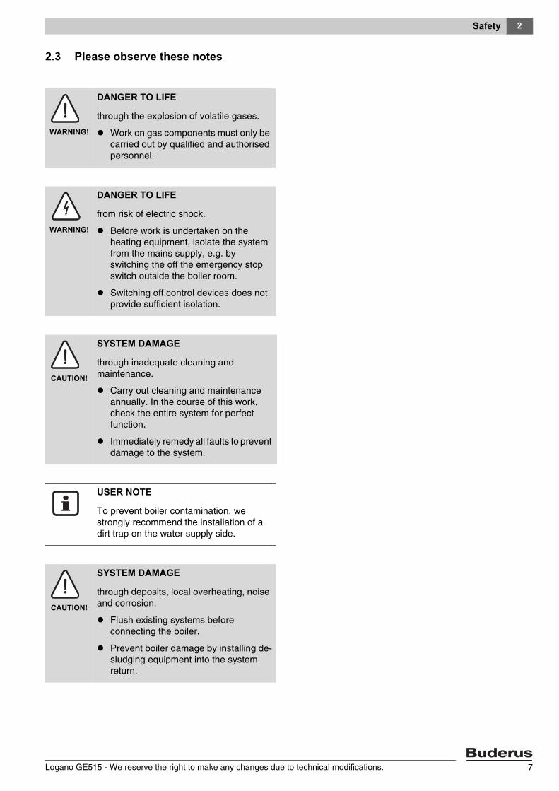
2.3 Please observe these notes
WARNING!
DANGER TO LIFE
through the explosion of volatile gases.
Work on gas components must only be carried out by qualified and authorised personnel.
WARNING!
DANGER TO LIFE
from risk of electric shock.
Before work is undertaken on the heating equipment, isolate the system from the mains supply, e.g. by switching the off the emergency stop switch outside the boiler room.
Switching off control devices does not provide sufficient isolation.
CAUTION!
SYSTEM DAMAGE
through inadequate cleaning and maintenance.
Carry out cleaning and maintenance annually. In the course of this work, check the entire system for perfect function.
Immediately remedy all faults to prevent damage to the system.
USER NOTE
To prevent boiler contamination, we strongly recommend the installation of a dirt trap on the water supply side.
CAUTION!
SYSTEM DAMAGE
through deposits, local overheating, noise and corrosion.
Flush existing systems before connecting the boiler.
Prevent boiler damage by installing de-sludging equipment into the system return.
Logano GE515 - We reserve the right to make any changes due to technical modifications. 7
Product description3
3 Product description
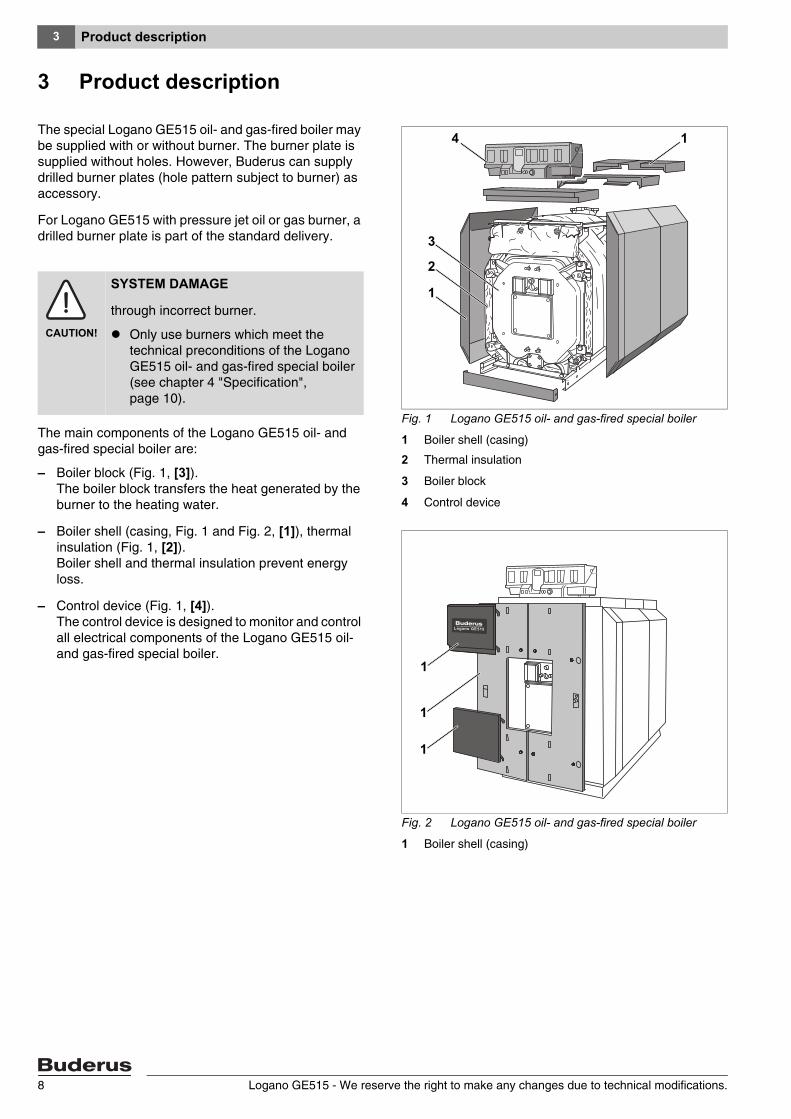
The special Logano GE515 oil- and gas-fired boiler may be supplied with or without burner. The burner plate is supplied without holes. However, Buderus can supply drilled burner plates (hole pattern subject to burner) as accessory.
For Logano GE515 with pressure jet oil or gas burner, a drilled burner plate is part of the standard delivery.
The main components of the Logano GE515 oil- and gas-fired special boiler are:
– Boiler block (Fig. 1, [3]). The boiler block transfers the heat generated by the burner to the heating water.
– Boiler shell (casing, Fig. 1 and Fig. 2, [1]), thermal insulation (Fig. 1, [2]). Boiler shell and thermal insulation prevent energy loss.
– Control device (Fig. 1, [4]). The control device is designed to monitor and control all electrical components of the Logano GE515 oil- and gas-fired special boiler.
Fig. 1 Logano GE515 oil- and gas-fired special boiler
1 Boiler shell (casing)
2 Thermal insulation
3 Boiler block
4 Control device
Fig. 2 Logano GE515 oil- and gas-fired special boiler
1 Boiler shell (casing)
2
3
4
1
1
1
1
1
CAUTION!
SYSTEM DAMAGE
through incorrect burner.
Only use burners which meet the technical preconditions of the Logano GE515 oil- and gas-fired special boiler (see chapter 4 "Specification", page 10).
Logano GE515 - We reserve the right to make any changes due to technical modifications.8
Product description 3
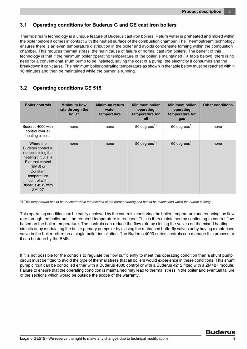
3.1 Operating conditions for Buderus G and GE cast iron boilers
Thermostream technology is a unique feature of Buderus cast iron boilers. Return water is preheated and mixed within the boiler before it comes in contact with the heated surface of the combustion chamber. The Thermostream technology ensures there is an even temperature distribution in the boiler and avoids condensate forming within the combustion chamber. This reduces thermal stress, the main cause of failure of normal cast iron boilers. The benefit of this technology is that if the minimum boiler operating temperature of the boiler is maintained ( table below), there is no need for a conventional shunt pump to be installed, saving the cost of a pump, the electricity it consumes and the breakdown it can cause. The minimum boiler operating temperature as shown in the table below must be reached within 10 minutes and then be maintained while the burner is running.
3.2 Operating conditions GE 515
1) This temperature has to be reached within ten minutes of the burner starting and has to be maintained whilst the burner is firing.
This operating condition can be easily achieved by the controls monitoring the boiler temperature and reducing the flow rate through the boiler until the required temperature is reached. This is then maintained by continuing to control flow based on the boiler temperature. The controls can reduce the flow rate by closing the valves on the mixed heating circuits or by modulating the boiler primary pumps or by closing the motorised butterfly valves or by having a motorised valve in the boiler return on a single boiler installation. The Buderus 4000 series controls can manage this process or it can be done by the BMS.
If it is not possible for the controls to regulate the flow sufficiently to meet this operating condition then a shunt pump circuit must be fitted to avoid the type of thermal stress that all boilers would experience in these conditions. This shunt pump circuit can be controlled either with a Buderus 4000 control or with a Buderus 4212 fitted with a ZM427 module. Failure to ensure that the operating condition is maintained may lead to thermal stress in the boiler and eventual failure of the sections which would be outside the scope of the warranty.
Boiler controls Minimum flow rate through the
boiler
Minimum return water
temperature
Minimum boiler operating
temperature for oil
Minimum boiler operating
temperature for gas
Other conditions
Buderus 4000 with control over all heating circuits
none none 50 degrees1) 50 degrees1) none
Where the Buderus control is not controlling the heating circuits ie External control
(BMS) orConstant
temperature control with
Buderus 4212 with ZM427
none none 50 degrees1) 60 degrees1) none
Logano GE515 - We reserve the right to make any changes due to technical modifications. 9
Specification4
4 Specification
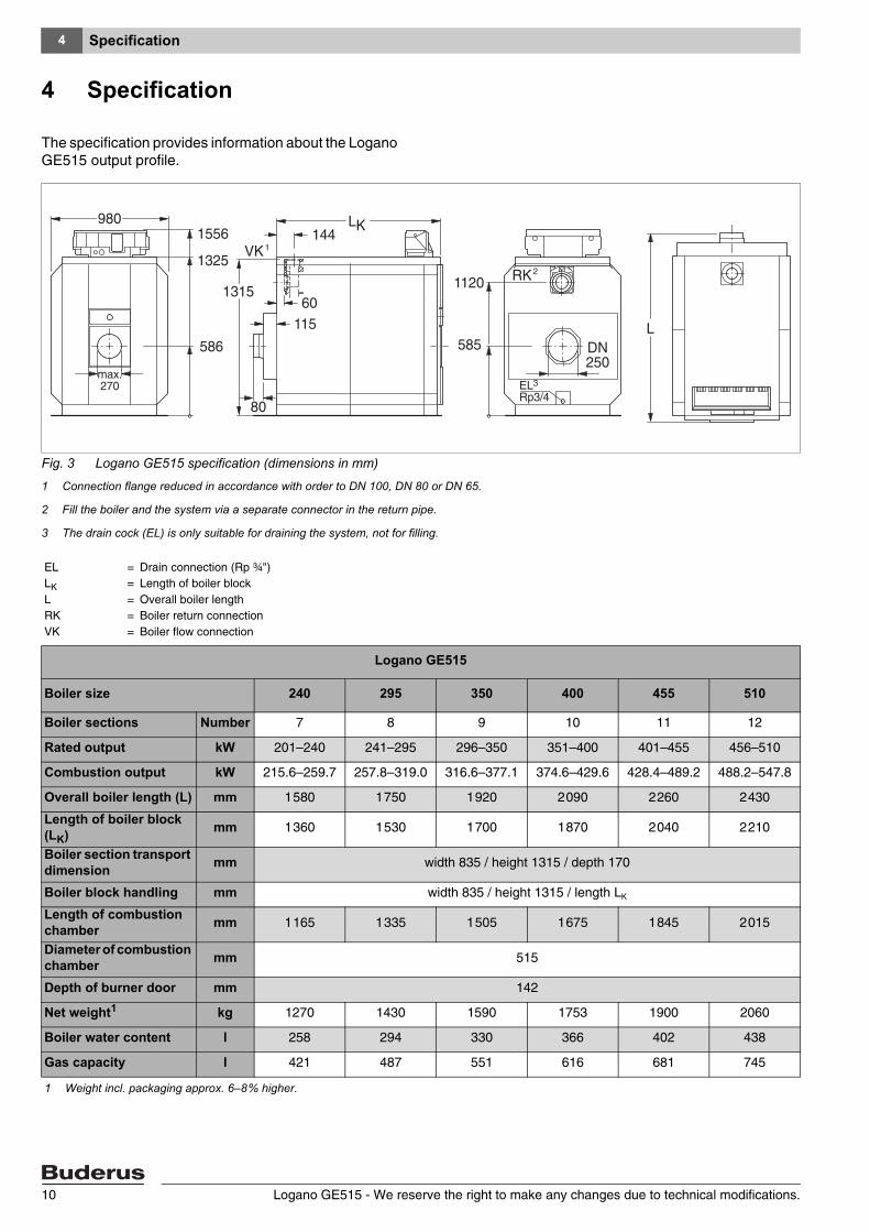
The specification provides information about the Logano GE515 output profile.
Fig. 3 Logano GE515 specification (dimensions in mm)
1 Connection flange reduced in accordance with order to DN 100, DN 80 or DN 65.
2 Fill the boiler and the system via a separate connector in the return pipe.
3 The drain cock (EL) is only suitable for draining the system, not for filling.
ELLKLRKVK
=====
Drain connection (Rp ¾")Length of boiler blockOverall boiler lengthBoiler return connectionBoiler flow connection
Logano GE515
Boiler size 240 295 350 400 455 510
Boiler sections Number 7 8 9 10 11 12
Rated output kW 201–240 241–295 296–350 351–400 401–455 456–510
Combustion output kW 215.6–259.7 257.8–319.0 316.6–377.1 374.6–429.6 428.4–489.2 488.2–547.8
Overall boiler length (L) mm 1 580 1 750 1 920 2 090 2 260 2 430
Length of boiler block (LK) mm 1 360 1 530 1 700 1 870 2 040 2 210
Boiler section transport dimension mm width 835 / height 1315 / depth 170
Boiler block handling mm width 835 / height 1315 / length LK
Length of combustion chamber mm 1 165 1 335 1 505 1 675 1 845 2 015
Diameter of combustion chamber mm 515
Depth of burner door mm 142
Net weight1 kg 1270 1430 1590 1753 1900 2060
Boiler water content l 258 294 330 366 402 438
Gas capacity l 421 487 551 616 681 745
1 Weight incl. packaging approx. 6–8 % higher.
Logano GE515 - We reserve the right to make any changes due to technical modifications.10

Specification 4
Logano GE515
Boiler size 240 295 350 400 455 510
Flue gas temperature2, part load (60 %) °C 138 138 140 129 130 140
Flue gas temperature2, full load °C 164–183 161–183 161–177 157–171 159–172 164–174
Flue gas volume flow, oil, part load (60 %) kg/s 0.0647 0.080 0.094 0.108 0.123 0.137
Flue gas volume flow, oil, full load3 kg/s 0.092–0.110 0.109–0.135 0,134–0,160 0.159–0.182 0.182–0.208 0.207–0.233
Flue gas volume flow, gas, part load (60 %) kg/s 0.065 0.080 0.095 0.108 0.123 0.138
Flue gas volume flow, gas, full load3 kg/s 0.092–0.111 0.110–0.136 0.135–0.161 0.160–0.183 0.183–0.208 0.208–0.233
CO2 content, oil % 13
CO2 content, gas % 10
Required pressure (draught) Pa 0
Flue gas resistance mbar 0.5–0.6 1.0–1.4 1.1–1.6 2.1–2.9 2.5–3.3 2.4–3.1
Maximum permissible flow temperature4 °C 100–1205
Maximum permissible operating pressure bar 6
Type approval number, boiler 06-226-640
CE designation, boiler CE - 0461 AR 6154
2 Acc. to DIN 303. The minimum flue gas temperature for the chimney calculation is approx. 12 K lower.
3 Full load details relate to the upper and lower rated output range.
4 High limit safety cut-out (safety limit thermostat). Max. possible flow temperature = safety limit (STB) –18 K. Example: Safety limit (STB)= 100 C; max. possible flow temperature = 100 – 18 = 82 °C.
5 In accordance with national standards and guidelines.
Logano GE515 - We reserve the right to make any changes due to technical modifications. 11
Standard delivery5
Logano GE515 - We reserve the right to make any changes due to technical modifications.12
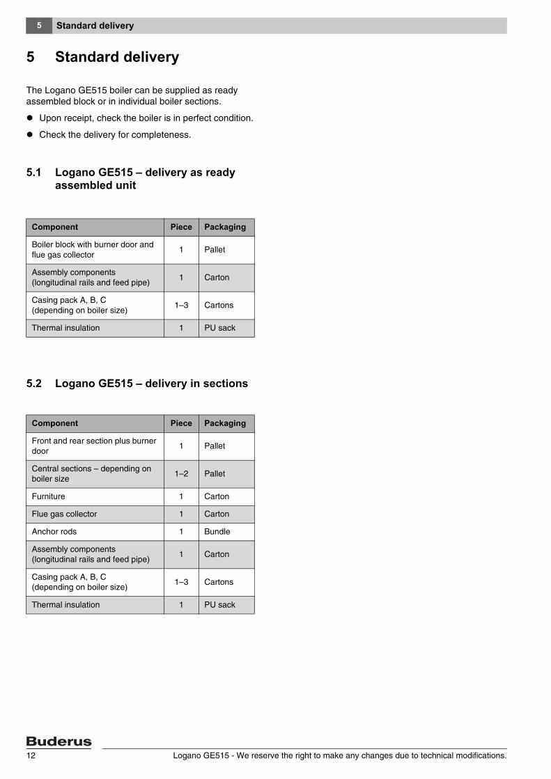
5 Standard delivery
The Logano GE515 boiler can be supplied as ready assembled block or in individual boiler sections.
Upon receipt, check the boiler is in perfect condition.
Check the delivery for completeness.
5.1 Logano GE515 – delivery as ready assembled unit
5.2 Logano GE515 – delivery in sections
Component Piece Packaging
Boiler block with burner door and flue gas collector
1 Pallet
Assembly components (longitudinal rails and feed pipe)
1 Carton
Casing pack A, B, C (depending on boiler size)
1–3 Cartons
Thermal insulation 1 PU sack
Component Piece Packaging
Front and rear section plus burner door
1 Pallet
Central sections – depending on boiler size
1–2 Pallet
Furniture 1 Carton
Flue gas collector 1 Carton
Anchor rods 1 Bundle
Assembly components (longitudinal rails and feed pipe)
1 Carton
Casing pack A, B, C (depending on boiler size)
1–3 Cartons
Thermal insulation 1 PU sack
Boiler handling 6
Logano GE515 - We reserve the right to make any changes due to technical modifications. 13
6 Boiler handling
Handle the individual boiler sections (loose delivery) plus other individual components with suitable means of transportation.
CAUTION!
DANGER OF INJURY
through inadequately secured boiler sections.
For your own safety, use only suitable means of transportation when handling individual boiler sections, e.g. a sack truck with strap or a stair truck, etc.
When handling, secure the boiler sections to the means of transport to prevent them slipping.
CAUTION!
SYSTEM DAMAGE
through impact.
The standard delivery of the Logano GE515 oil- and gas-fired special boiler comprises components which are sensitive to impact.
When handling the boiler (sections), protect electronic and other components against impact.
Please note the handling references on the packaging.
CAUTION!
SYSTEM DAMAGE
through contamination.
Note the following if the boiler is to be stored in its assembled condition:
Protect boiler connections by closing or sealing them off.
USER NOTE
Dispose of packaging in an environmentally responsible manner.
Boiler positioning7
7 Boiler positioning
In this chapter you will learn how to correctly position the Logano GE515.
7.1 Tools and accessories
The following tools and auxiliary materials are required for the boiler assembly (the listed items must be provided by the installer):
– Boiler compression tool 2.2 (Fig. 4, page 15) or 2.3 (Fig. 5, page 15)
– Boiler installation template for fitting the boiler sections together
– Steel hammer and wooden or rubber mallet
– Half-round bastard file
– Screwdrivers (Philips and flat bladed)
– Flat chisel
– Spanner SW 13, 19, 24, 36 and Allen key SW 19
– Support wedge, flat iron
– Cleaning rags and cloth
– Fine emery cloth
– Wire brush
– 3-in-1 oil
– Solvent (petrol or solution)
– Spirit level, ruler, chalk, straight edge
– Blanking flange with vent facility (for pressure test)
CAUTION!
SYSTEM DAMAGE
through frost.
Install the system in a room which has been protected from frost.
Logano GE515 - We reserve the right to make any changes due to technical modifications.14

Boiler positioning 7
7.1.1 Boiler compression tool size 2.2
7.1.2 Boiler compression tool 2.3 (complete in the toolbox)
Fig. 4 Boiler compression tool size 2.2 (dimensions in mm)
1 Mating flange
2 Additional flange
3 Compression unit
4 Pull rod
5 Extension
6 Cylindrical pin (size 2.2)
123
4 5
6
Boiler sections
Compression tool per
boiler hub
Extension piece per boiler hub
Dimensions (overall) in
mm
7–10 1 0 2 160
11–12 1 1 2 760
Fig. 5 Boiler compression tool size 2.3 (dimensions in mm)
1 Mating flange
2 Additional flange
3 Compression unit
4 Pull rod
5 Extension
6 Wedge (size 2.3)
6123
4 5Boiler
sections
Compression tool per
boiler hub
Extension piece per boiler hub
Dimensions (overall) in
mm
7–12 1 3 3 080
Logano GE515 - We reserve the right to make any changes due to technical modifications. 15
Boiler positioning7
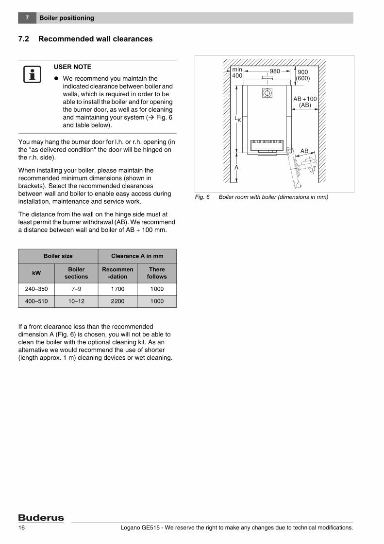
7.2 Recommended wall clearances
You may hang the burner door for l.h. or r.h. opening (in the "as delivered condition" the door will be hinged on the r.h. side).
When installing your boiler, please maintain the recommended minimum dimensions (shown in brackets). Select the recommended clearances between wall and boiler to enable easy access during installation, maintenance and service work.
The distance from the wall on the hinge side must at least permit the burner withdrawal (AB). We recommend a distance between wall and boiler of AB + 100 mm.
If a front clearance less than the recommended dimension A (Fig. 6) is chosen, you will not be able to clean the boiler with the optional cleaning kit. As an alternative we would recommend the use of shorter (length approx. 1 m) cleaning devices or wet cleaning.
Fig. 6 Boiler room with boiler (dimensions in mm)
USER NOTE
We recommend you maintain the indicated clearance between boiler and walls, which is required in order to be able to install the boiler and for opening the burner door, as well as for cleaning and maintaining your system ( Fig. 6 and table below).
Boiler size Clearance A in mm
kW Boiler sections
Recommen-dation
There follows
240–350 7–9 1 700 1 000
400–510 10–12 2 200 1 000
Logano GE515 - We reserve the right to make any changes due to technical modifications.16

Boiler positioning 7
7.3 Positioning the boiler on a sub-structure or on foundations
You can cast a concrete plinth if the optional boiler plinth is not used. When casting the plinth, you must incorporate a steel angle with the dimensions 100 x 50 x 8 mm or a steel strip with the dimensions 100 x 5 mm ( Fig. 7 and the following table), to ensure the boiler sections will slide into position during installation.
It is advantageous to position the boiler on a plinth 50 - 80 cm high (Fig. 7, [1]). The support surface must be perfectly flat and level. The front edge of the boiler should be flush with the edge of the foundation.
Fig. 7 Foundation dimensions in mm
1
USER NOTE
As accessory Buderus offers a boiler plinth designed to reduce body resonance.
USER NOTE
When casting the foundation, note the side to which the burner will be pivoted (burner door hinged on the r.h. or l.h. side, Fig. 6, page 16).
Number of boiler sections
L1 (foundation)in mm
L2 (length of steel section)
in mm
7 1 360 1 190
8 1 530 1 360
9 1 700 1 530
10 1 870 1 700
11 2 040 1 870
12 2 210 2 040
Logano GE515 - We reserve the right to make any changes due to technical modifications. 17
Boiler block assembly8
8 Boiler block assembly
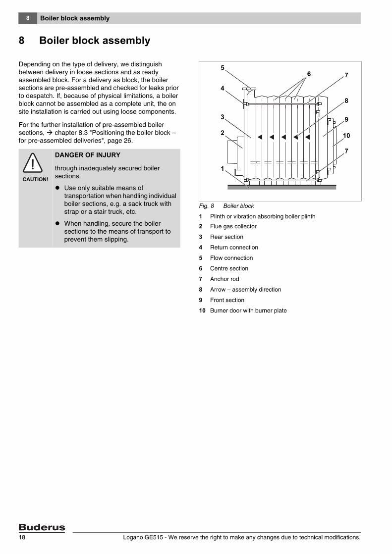
Depending on the type of delivery, we distinguish between delivery in loose sections and as ready assembled block. For a delivery as block, the boiler sections are pre-assembled and checked for leaks prior to despatch. If, because of physical limitations, a boiler block cannot be assembled as a complete unit, the on site installation is carried out using loose components.
For the further installation of pre-assembled boiler sections, chapter 8.3 "Positioning the boiler block – for pre-assembled deliveries", page 26.
Fig. 8 Boiler block
1 Plinth or vibration absorbing boiler plinth
2 Flue gas collector
3 Rear section
4 Return connection
5 Flow connection
6 Centre section
7 Anchor rod
8 Arrow – assembly direction
9 Front section
10 Burner door with burner plate
1
2
3
6 7
8
10
7
9
4
5
CAUTION!
DANGER OF INJURY
through inadequately secured boiler sections.
Use only suitable means of transportation when handling individual boiler sections, e.g. a sack truck with strap or a stair truck, etc.
When handling, secure the boiler sections to the means of transport to prevent them slipping.
Logano GE515 - We reserve the right to make any changes due to technical modifications.18
Boiler block assembly 8
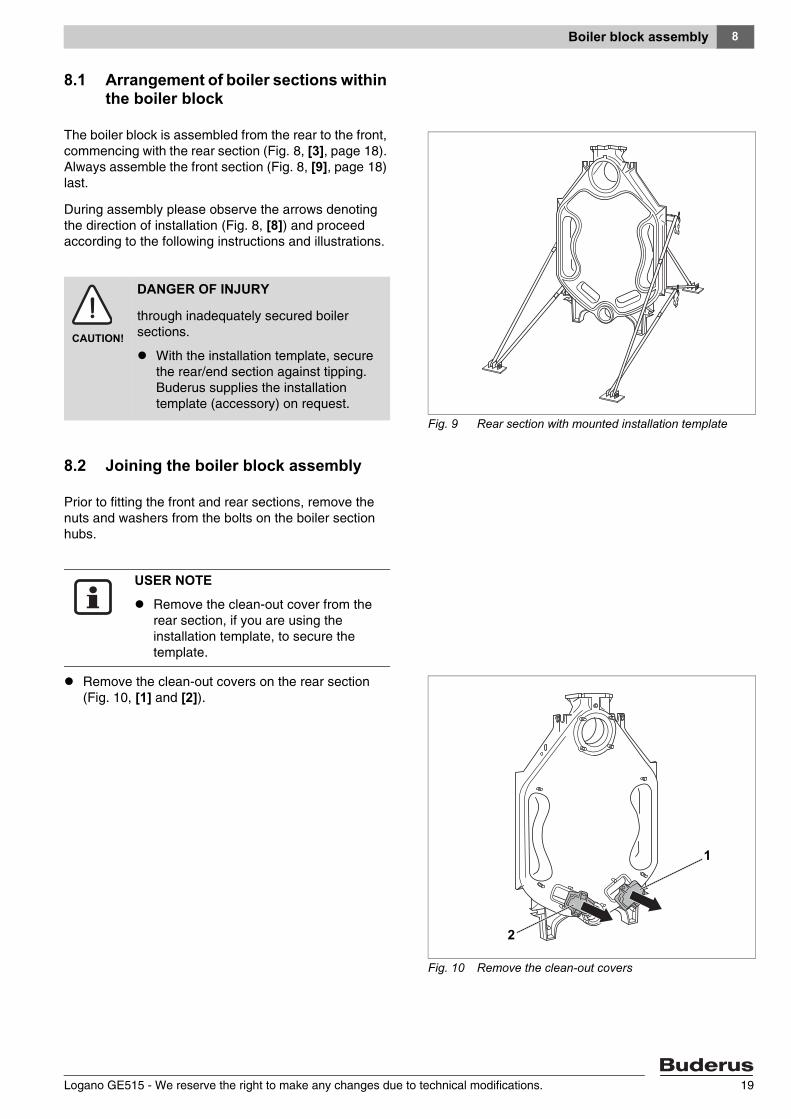
8.1 Arrangement of boiler sections within the boiler block
The boiler block is assembled from the rear to the front, commencing with the rear section (Fig. 8, [3], page 18). Always assemble the front section (Fig. 8, [9], page 18) last.
During assembly please observe the arrows denoting the direction of installation (Fig. 8, [8]) and proceed according to the following instructions and illustrations.
8.2 Joining the boiler block assembly
Prior to fitting the front and rear sections, remove the nuts and washers from the bolts on the boiler section hubs.
Remove the clean-out covers on the rear section (Fig. 10, [1] and [2]).
Fig. 9 Rear section with mounted installation template
CAUTION!
DANGER OF INJURY
through inadequately secured boiler sections.
With the installation template, secure the rear/end section against tipping. Buderus supplies the installation template (accessory) on request.
USER NOTE
Remove the clean-out cover from the rear section, if you are using the installation template, to secure the template.
Fig. 10 Remove the clean-out covers
2
1
Logano GE515 - We reserve the right to make any changes due to technical modifications. 19
Boiler block assembly8
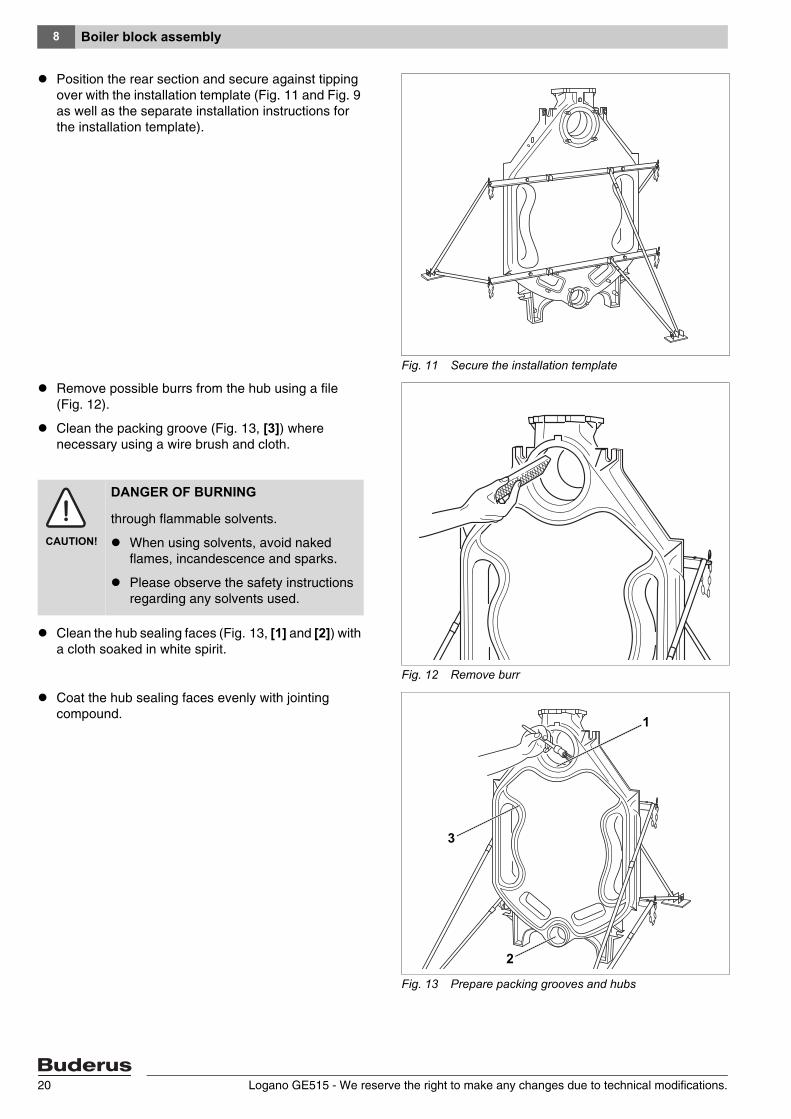
Position the rear section and secure against tipping over with the installation template (Fig. 11 and Fig. 9 as well as the separate installation instructions for the installation template).
Remove possible burrs from the hub using a file (Fig. 12).
Clean the packing groove (Fig. 13, [3]) where necessary using a wire brush and cloth.
Clean the hub sealing faces (Fig. 13, [1] and [2]) with a cloth soaked in white spirit.
Coat the hub sealing faces evenly with jointing compound.
Fig. 11 Secure the installation template
Fig. 12 Remove burr
CAUTION!
DANGER OF BURNING
through flammable solvents.
When using solvents, avoid naked flames, incandescence and sparks.
Please observe the safety instructions regarding any solvents used.
Fig. 13 Prepare packing grooves and hubs
2
1
3
Logano GE515 - We reserve the right to make any changes due to technical modifications.20
Boiler block assembly 8
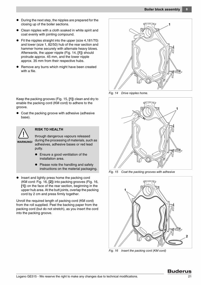
During the next step, the nipples are prepared for the closing up of the boiler sections.
Clean nipples with a cloth soaked in white spirit and coat evenly with jointing compound.
Fit the nipples straight into the upper (size 4,181/70) and lower (size 1, 82/50) hub of the rear section and hammer home securely with alternate heavy blows. Afterwards, the upper nipple (Fig. 14, [1]) should protrude approx. 45 mm, and the lower nipple approx. 35 mm from their respective hubs.
Remove any burrs which might have been created with a file.
Keep the packing grooves (Fig. 15, [1]) clean and dry to enable the packing cord (KM cord) to adhere to the groove.
Coat the packing groove with adhesive (adhesive base).
Insert and lightly press home the packing cord (KM cord: Fig. 16, [2]) into packing grooves (Fig. 16, [1]) on the face of the rear section, beginning in the upper hub area. At the butt joints, overlap the packing cord by 2 cm and press firmly together.
Unroll the required length of packing cord (KM cord) from the roll supplied. Peel the backing paper from the packing cord (but do not stretch), as you insert the cord into the packing groove.
Fig. 14 Drive nipples home.
1
Fig. 15 Coat the packing grooves with adhesive
1
WARNUNG!
RISK TO HEALTH
through dangerous vapours released during the processing of materials, such as adhesives, adhesive bases or red lead putty.
Ensure a good ventilation of the installation area.
Please note the handling and safety instructions on the material packaging.
Fig. 16 Insert the packing cord (KM cord)
2
1
Logano GE515 - We reserve the right to make any changes due to technical modifications. 21
Boiler block assembly8
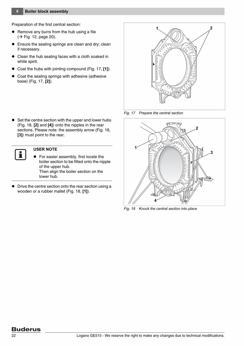
Preparation of the first central section:
Remove any burrs from the hub using a file ( Fig. 12, page 20).
Ensure the sealing springs are clean and dry; clean if necessary.
Clean the hub sealing faces with a cloth soaked in white spirit.
Coat the hubs with jointing compound (Fig. 17, [1]).
Coat the sealing springs with adhesive (adhesive base) (Fig. 17, [2]).
Set the centre section with the upper and lower hubs (Fig. 18, [2] and [4]) onto the nipples in the rear sections. Please note: the assembly arrow (Fig. 18, [3]) must point to the rear.
Drive the centre section onto the rear section using a wooden or a rubber mallet (Fig. 18, [1]).
Fig. 17 Prepare the central section
1 2
Fig. 18 Knock the central section into place
1
2
3
4
USER NOTE
For easier assembly, first locate the boiler section to be fitted onto the nipple of the upper hub. Then align the boiler section on the lower hub.
Logano GE515 - We reserve the right to make any changes due to technical modifications.22
Boiler block assembly 8
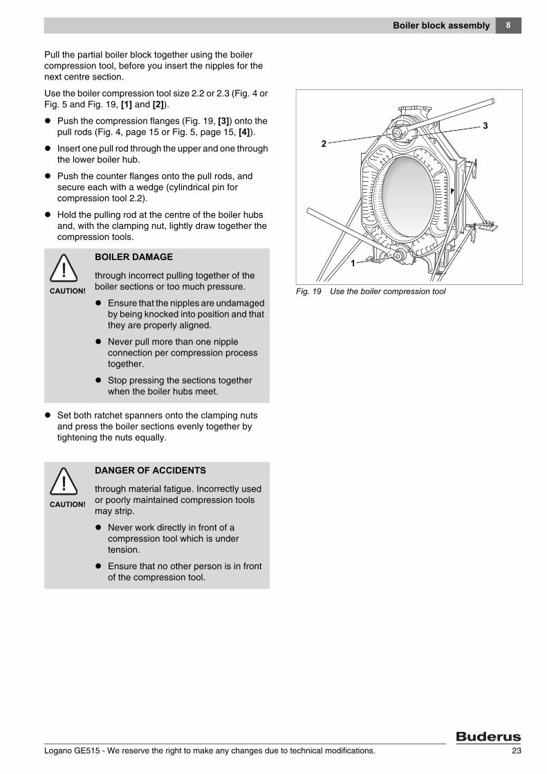
Pull the partial boiler block together using the boiler compression tool, before you insert the nipples for the next centre section.
Use the boiler compression tool size 2.2 or 2.3 (Fig. 4 or Fig. 5 and Fig. 19, [1] and [2]).
Push the compression flanges (Fig. 19, [3]) onto the pull rods (Fig. 4, page 15 or Fig. 5, page 15, [4]).
Insert one pull rod through the upper and one through the lower boiler hub.
Push the counter flanges onto the pull rods, and secure each with a wedge (cylindrical pin for compression tool 2.2).
Hold the pulling rod at the centre of the boiler hubs and, with the clamping nut, lightly draw together the compression tools.
Set both ratchet spanners onto the clamping nuts and press the boiler sections evenly together by tightening the nuts equally.
Fig. 19 Use the boiler compression tool
2
1
3
CAUTION!
BOILER DAMAGE
through incorrect pulling together of the boiler sections or too much pressure.
Ensure that the nipples are undamaged by being knocked into position and that they are properly aligned.
Never pull more than one nipple connection per compression process together.
Stop pressing the sections together when the boiler hubs meet.
CAUTION!
DANGER OF ACCIDENTS
through material fatigue. Incorrectly used or poorly maintained compression tools may strip.
Never work directly in front of a compression tool which is under tension.
Ensure that no other person is in front of the compression tool.
Logano GE515 - We reserve the right to make any changes due to technical modifications. 23
Boiler block assembly8
Loosen and remove boiler compression tool.
Check nipples for correct seating.
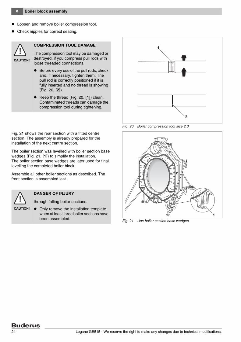
Fig. 21 shows the rear section with a fitted centre section. The assembly is already prepared for the installation of the next centre section.
The boiler section was levelled with boiler section base wedges (Fig. 21, [1]) to simplify the installation. The boiler section base wedges are later used for final levelling the completed boiler block.
Assemble all other boiler sections as described. The front section is assembled last.
Fig. 20 Boiler compression tool size 2.3
1
2
CAUTION!
COMPRESSION TOOL DAMAGE
The compression tool may be damaged or destroyed, if you compress pull rods with loose threaded connections.
Before every use of the pull rods, check and, if necessary, tighten them. The pull rod is correctly positioned if it is fully inserted and no thread is showing (Fig. 20, [2]).
Keep the thread (Fig. 20, [1]) clean. Contaminated threads can damage the compression tool during tightening.
Fig. 21 Use boiler section base wedges
11CAUTION!
DANGER OF INJURY
through falling boiler sections.
Only remove the installation template when at least three boiler sections have been assembled.
Logano GE515 - We reserve the right to make any changes due to technical modifications.24

Boiler block assembly 8
Insert the anchor rods with fitted spring kits on the l.h. and r.h. sides, on the top and bottom adjacent to the boiler hubs, into the cast lugs (Fig. 22, [1] to [4]).
Tighten the nuts by hand.
Now tighten the nuts on each anchor rod by 1 to 1½ turns.
Align the boiler on the plinth or vibration absorbing plinth in the horizontal and vertical plane ( chapter 7 "Boiler positioning", page 14).
Remove the boiler compression tool.
Install the feed pipe in the next installation step ( chapter 8.4 "Sliding the feed pipe into place (carton of installation components)", page 27).
USER NOTE
Loosen the compression tool – but do not remove - after the front section has been assembled. First inset the anchor rods.
Fig. 22 Install the anchor rods
2
1
3
4
CAUTION!
SYSTEM DAMAGE
through inadequate compression force.
Do not unwind the spring kit. Use it only in its original state.
Logano GE515 - We reserve the right to make any changes due to technical modifications. 25
Boiler block assembly8
8.3 Positioning the boiler block – for pre-assembled deliveries
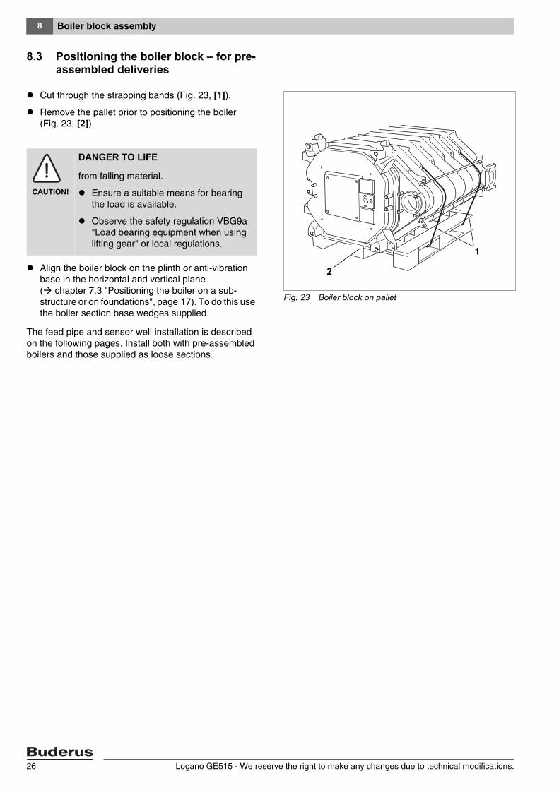
Cut through the strapping bands (Fig. 23, [1]).
Remove the pallet prior to positioning the boiler (Fig. 23, [2]).
Align the boiler block on the plinth or anti-vibration base in the horizontal and vertical plane ( chapter 7.3 "Positioning the boiler on a sub-structure or on foundations", page 17). To do this use the boiler section base wedges supplied
The feed pipe and sensor well installation is described on the following pages. Install both with pre-assembled boilers and those supplied as loose sections.
Fig. 23 Boiler block on pallet
1
2
CAUTION!
DANGER TO LIFE
from falling material.
Ensure a suitable means for bearing the load is available.
Observe the safety regulation VBG9a "Load bearing equipment when using lifting gear" or local regulations.
Logano GE515 - We reserve the right to make any changes due to technical modifications.26
Boiler block assembly 8
8.4 Sliding the feed pipe into place (carton of installation components)
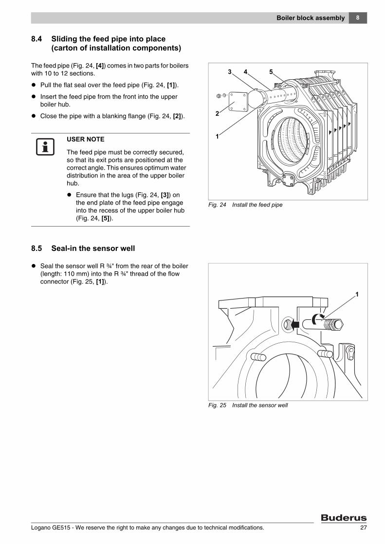
The feed pipe (Fig. 24, [4]) comes in two parts for boilers with 10 to 12 sections.
Pull the flat seal over the feed pipe (Fig. 24, [1]).
Insert the feed pipe from the front into the upper boiler hub.
Close the pipe with a blanking flange (Fig. 24, [2]).
8.5 Seal-in the sensor well
Seal the sensor well R ¾" from the rear of the boiler (length: 110 mm) into the R ¾" thread of the flow connector (Fig. 25, [1]).
Fig. 24 Install the feed pipe
1
3 4 5
2
USER NOTE
The feed pipe must be correctly secured, so that its exit ports are positioned at the correct angle. This ensures optimum water distribution in the area of the upper boiler hub.
Ensure that the lugs (Fig. 24, [3]) on the end plate of the feed pipe engage into the recess of the upper boiler hub (Fig. 24, [5]).
Fig. 25 Install the sensor well
1
Logano GE515 - We reserve the right to make any changes due to technical modifications. 27
Boiler block assembly8
8.6 Leak test
Carry out a boiler block leak test if the sections were delivered loose. Pre-assembled sections are leak tested in the factory.
For the further installation of pre-assembled boiler sections ( chapter 11 "Burner installation", page 49).
8.6.1 Preparing the leak test
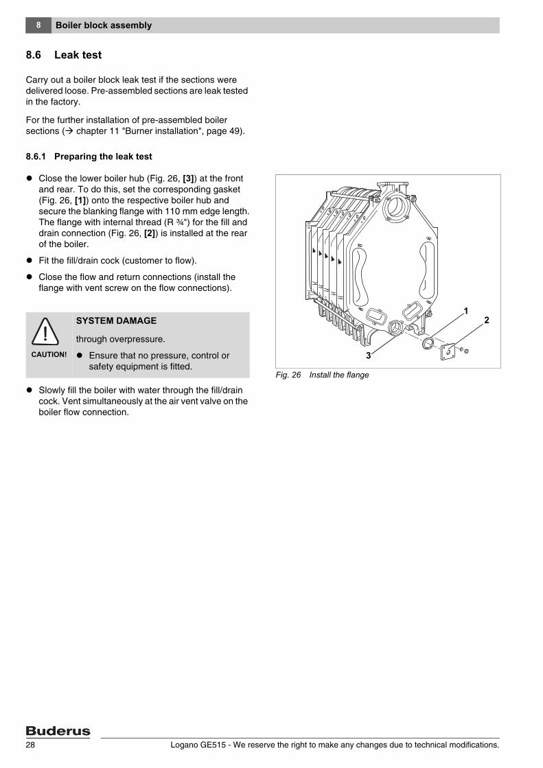
Close the lower boiler hub (Fig. 26, [3]) at the front and rear. To do this, set the corresponding gasket (Fig. 26, [1]) onto the respective boiler hub and secure the blanking flange with 110 mm edge length. The flange with internal thread (R ¾") for the fill and drain connection (Fig. 26, [2]) is installed at the rear of the boiler.
Fit the fill/drain cock (customer to flow).
Close the flow and return connections (install the flange with vent screw on the flow connections).
Slowly fill the boiler with water through the fill/drain cock. Vent simultaneously at the air vent valve on the boiler flow connection.
Fig. 26 Install the flange
1
3
2
CAUTION!
SYSTEM DAMAGE
through overpressure.
Ensure that no pressure, control or safety equipment is fitted.
Logano GE515 - We reserve the right to make any changes due to technical modifications.28
Boiler block assembly 8
8.6.2 Leak test
Carry out a leak test with a pressure of 8.6 bar (in accordance with the requirements of the European Pressure Vessel Guideline).
Use a pressure gauge class 1.0 for measuring the pressure.
If a hub connection is leaking, first drain the water through the fill/drain cock.
Remove the feed pipe.
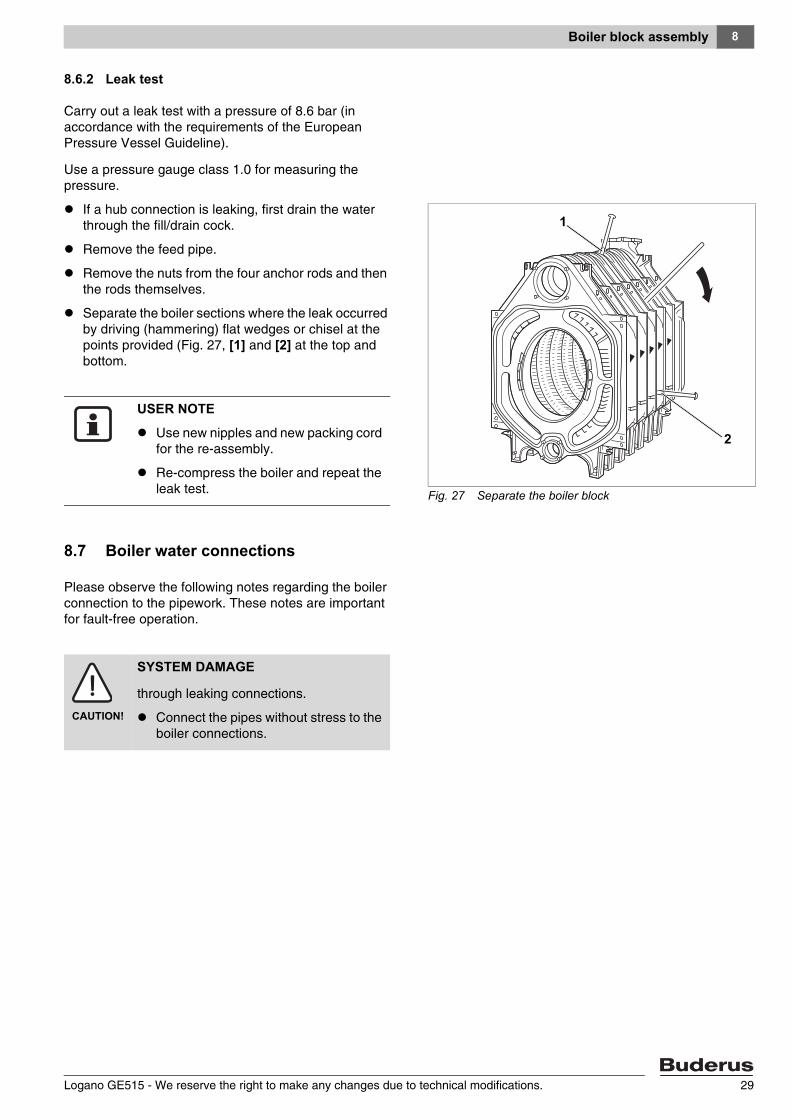
Remove the nuts from the four anchor rods and then the rods themselves.
Separate the boiler sections where the leak occurred by driving (hammering) flat wedges or chisel at the points provided (Fig. 27, [1] and [2] at the top and bottom.
8.7 Boiler water connections
Please observe the following notes regarding the boiler connection to the pipework. These notes are important for fault-free operation.
Fig. 27 Separate the boiler block
1
2
USER NOTE
Use new nipples and new packing cord for the re-assembly.
Re-compress the boiler and repeat the leak test.
CAUTION!
SYSTEM DAMAGE
through leaking connections.
Connect the pipes without stress to the boiler connections.
Logano GE515 - We reserve the right to make any changes due to technical modifications. 29
Boiler block assembly8
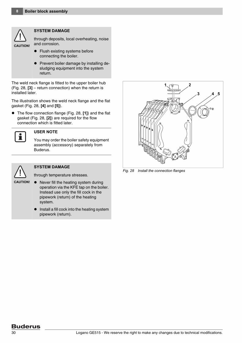
The weld neck flange is fitted to the upper boiler hub (Fig. 28, [3] – return connection) when the return is installed later.
The illustration shows the weld neck flange and the flat gasket (Fig. 28, [4] and [5]).
The flow connection flange (Fig. 28, [1]) and the flat gasket (Fig. 28, [2]) are required for the flow connection which is fitted later.
CAUTION!
SYSTEM DAMAGE
through deposits, local overheating, noise and corrosion.
Flush existing systems before connecting the boiler.
Prevent boiler damage by installing de-sludging equipment into the system return.
Fig. 28 Install the connection flanges
53
21
4
USER NOTE
You may order the boiler safety equipment assembly (accessory) separately from Buderus.
CAUTION!
SYSTEM DAMAGE
through temperature stresses.
Never fill the heating system during operation via the KFE tap on the boiler. Instead use only the fill cock in the pipework (return) of the heating system.
Install a fill cock into the heating system pipework (return).
Logano GE515 - We reserve the right to make any changes due to technical modifications.30
Boiler block assembly 8
8.8 Installing boiler fittings and the burner door
In contrast to the delivery in sections, the burner door and the flue gas collector are already fitted to the boiler in the factory, if the boiler is supplied as pre-assembled block.
8.8.1 Positioning the flue gas collector
The GP packing cord (glass fibre cord with silicone sheath) is already inserted into the flue gas collector at the factory.
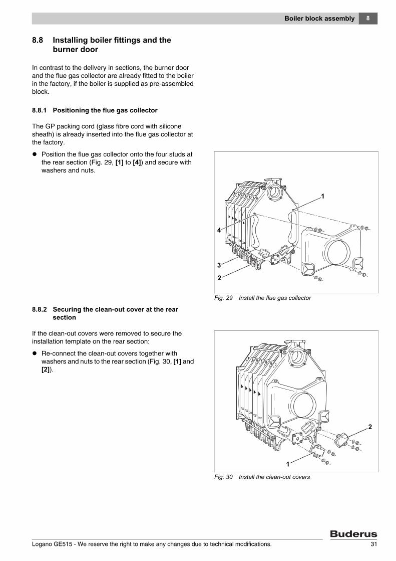
Position the flue gas collector onto the four studs at the rear section (Fig. 29, [1] to [4]) and secure with washers and nuts.
8.8.2 Securing the clean-out cover at the rear section
If the clean-out covers were removed to secure the installation template on the rear section:
Re-connect the clean-out covers together with washers and nuts to the rear section (Fig. 30, [1] and [2]).
Fig. 29 Install the flue gas collector
1
2
4
3
Fig. 30 Install the clean-out covers
1
2
Logano GE515 - We reserve the right to make any changes due to technical modifications. 31
Boiler block assembly8
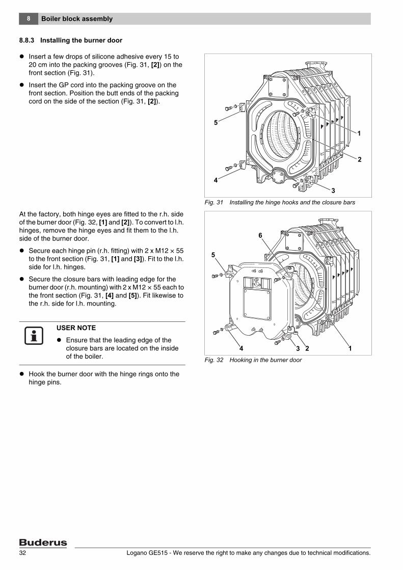
8.8.3 Installing the burner door
Insert a few drops of silicone adhesive every 15 to 20 cm into the packing grooves (Fig. 31, [2]) on the front section (Fig. 31).
Insert the GP cord into the packing groove on the front section. Position the butt ends of the packing cord on the side of the section (Fig. 31, [2]).
At the factory, both hinge eyes are fitted to the r.h. side of the burner door (Fig. 32, [1] and [2]). To convert to l.h. hinges, remove the hinge eyes and fit them to the l.h. side of the burner door.
Secure each hinge pin (r.h. fitting) with 2 x M12 × 55 to the front section (Fig. 31, [1] and [3]). Fit to the l.h. side for l.h. hinges.
Secure the closure bars with leading edge for the burner door (r.h. mounting) with 2 x M12 × 55 each to the front section (Fig. 31, [4] and [5]). Fit likewise to the r.h. side for l.h. mounting.
Hook the burner door with the hinge rings onto the hinge pins.
Fig. 31 Installing the hinge hooks and the closure bars
1
2
34
5
Fig. 32 Hooking in the burner door
134
5
6
2
USER NOTE
Ensure that the leading edge of the closure bars are located on the inside of the boiler.
Logano GE515 - We reserve the right to make any changes due to technical modifications.32
Boiler block assembly 8
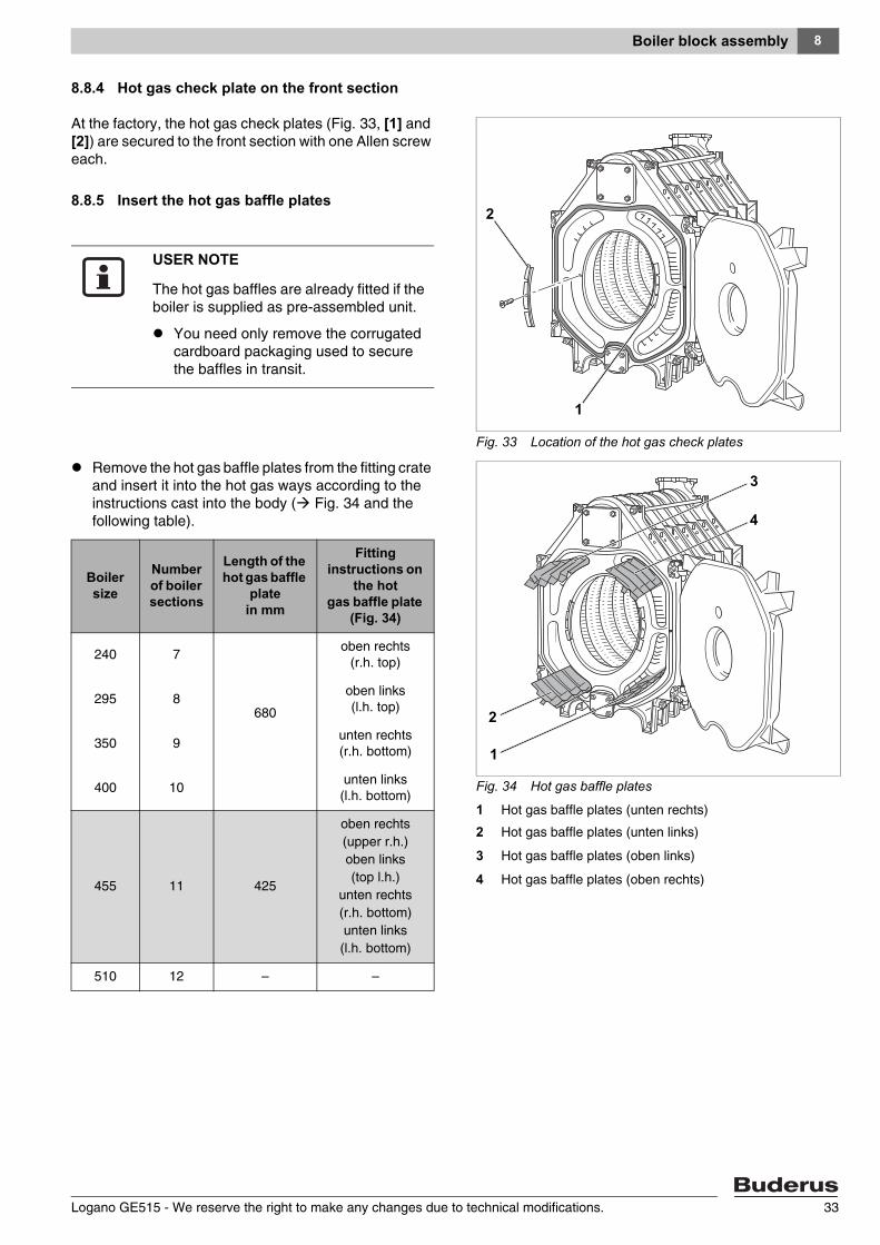
8.8.4 Hot gas check plate on the front section
At the factory, the hot gas check plates (Fig. 33, [1] and [2]) are secured to the front section with one Allen screw each.
8.8.5 Insert the hot gas baffle plates
Remove the hot gas baffle plates from the fitting crate and insert it into the hot gas ways according to the instructions cast into the body ( Fig. 34 and the following table).
Fig. 33 Location of the hot gas check plates
2
1
USER NOTE
The hot gas baffles are already fitted if the boiler is supplied as pre-assembled unit.
You need only remove the corrugated cardboard packaging used to secure the baffles in transit.
Fig. 34 Hot gas baffle plates
1 Hot gas baffle plates (unten rechts)
2 Hot gas baffle plates (unten links)
3 Hot gas baffle plates (oben links)
4 Hot gas baffle plates (oben rechts)
3
4
2
1
Boiler size
Number of boiler sections
Length of the hot gas baffle
platein mm
Fitting instructions on
the hotgas baffle plate
(Fig. 34)
240 7
680
oben rechts(r.h. top)
295 8oben links(l.h. top)
350 9unten rechts(r.h. bottom)
400 10unten links(l.h. bottom)
455 11 425
oben rechts(upper r.h.)oben links(top l.h.)
unten rechts(r.h. bottom)unten links(l.h. bottom)
510 12 – –
Logano GE515 - We reserve the right to make any changes due to technical modifications. 33
Boiler block assembly8
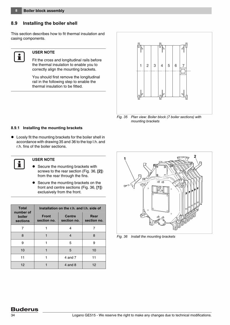
8.9 Installing the boiler shell
This section describes how to fit thermal insulation and casing components.
8.9.1 Installing the mounting brackets
Loosly fit the mounting brackets for the boiler shell in accordance with drawing 35 and 36 to the top l.h. and r.h. fins of the boiler sections.
Fig. 35 Plan view: Boiler block (7 boiler sections) with mounting brackets
USER NOTE
Fit the cross and longitudinal rails before the thermal insulation to enable you to correctly align the mounting brackets.
You should first remove the longitudinal rail in the following step to enable the thermal insulation to be fitted.
Fig. 36 Install the mounting brackets
21USER NOTE
Secure the mounting brackets with screws to the rear section (Fig. 36, [2]) from the rear through the fins.
Secure the mounting brackets on the front and centre sections (Fig. 36, [1]) exclusively from the front.
Total number of
boiler sections
Installation on the r.h. and l.h. side of
Front section no.
Centre section no.
Rear section no.
7 1 4 7
8 1 4 8
9 1 5 9
10 1 5 10
11 1 4 and 7 11
12 1 4 and 8 12
Logano GE515 - We reserve the right to make any changes due to technical modifications.34
Boiler block assembly 8
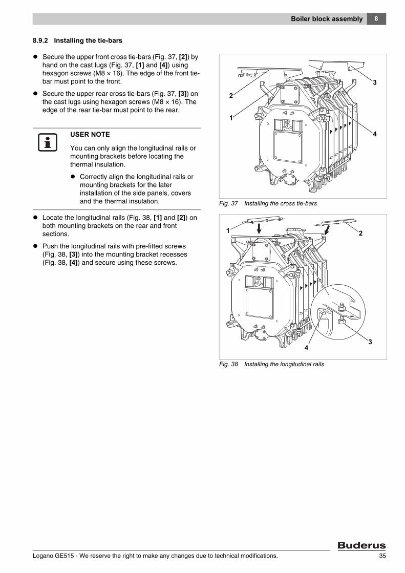
8.9.2 Installing the tie-bars
Secure the upper front cross tie-bars (Fig. 37, [2]) by hand on the cast lugs (Fig. 37, [1] and [4]) using hexagon screws (M8 × 16). The edge of the front tie-bar must point to the front.
Secure the upper rear cross tie-bars (Fig. 37, [3]) on the cast lugs using hexagon screws (M8 × 16). The edge of the rear tie-bar must point to the rear.
Locate the longitudinal rails (Fig. 38, [1] and [2]) on both mounting brackets on the rear and front sections.
Push the longitudinal rails with pre-fitted screws (Fig. 38, [3]) into the mounting bracket recesses (Fig. 38, [4]) and secure using these screws.
Fig. 37 Installing the cross tie-bars
2
3
1
4USER NOTE
You can only align the longitudinal rails or mounting brackets before locating the thermal insulation.
Correctly align the longitudinal rails or mounting brackets for the later installation of the side panels, covers and the thermal insulation.
Fig. 38 Installing the longitudinal rails
1
34
2
Logano GE515 - We reserve the right to make any changes due to technical modifications. 35
Boiler block assembly8
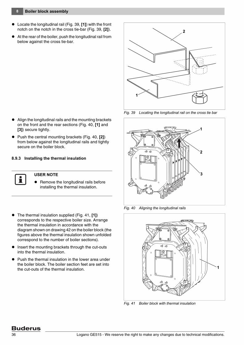
Locate the longitudinal rail (Fig. 39, [1]) with the front notch on the notch in the cross tie-bar (Fig. 39, [2]).
At the rear of the boiler, push the longitudinal rail from below against the cross tie-bar.
Align the longitudinal rails and the mounting brackets on the front and the rear sections (Fig. 40, [1] and [3]) secure tightly.
Push the central mounting brackets (Fig. 40, [2]) from below against the longitudinal rails and tightly secure on the boiler block.
8.9.3 Installing the thermal insulation
The thermal insulation supplied (Fig. 41, [1]) corresponds to the respective boiler size. Arrange the thermal insulation in accordance with the diagram shown on drawing 42 on the boiler block (the figures above the thermal insulation shown unfolded correspond to the number of boiler sections).
Insert the mounting brackets through the cut-outs into the thermal insulation.
Push the thermal insulation in the lower area under the boiler block. The boiler section feet are set into the cut-outs of the thermal insulation.
Fig. 39 Locating the longitudinal rail on the cross tie bar
1
2
Fig. 40 Aligning the longitudinal rails
1
3
2
USER NOTE
Remove the longitudinal rails before installing the thermal insulation.
Fig. 41 Boiler block with thermal insulation
1
Logano GE515 - We reserve the right to make any changes due to technical modifications.36
Boiler block assembly 8
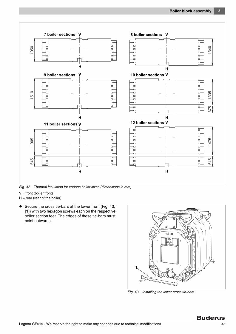
Secure the cross tie-bars at the lower front (Fig. 43, [1]) with two hexagon screws each on the respective boiler section feet. The edges of these tie-bars must point outwards.
Fig. 42 Thermal insulation for various boiler sizes (dimensions in mm)
V = front (boiler front)H = rear (rear of the boiler)
7 boiler sections
9 boiler sections
11 boiler sections
8 boiler sections
10 boiler sections
12 boiler sections
V V
V
V
V
V
H
H
H
H
H
H
H
8 boiler sections
Fig. 43 Installing the lower cross tie-bars
1
Logano GE515 - We reserve the right to make any changes due to technical modifications. 37
Boiler block assembly8
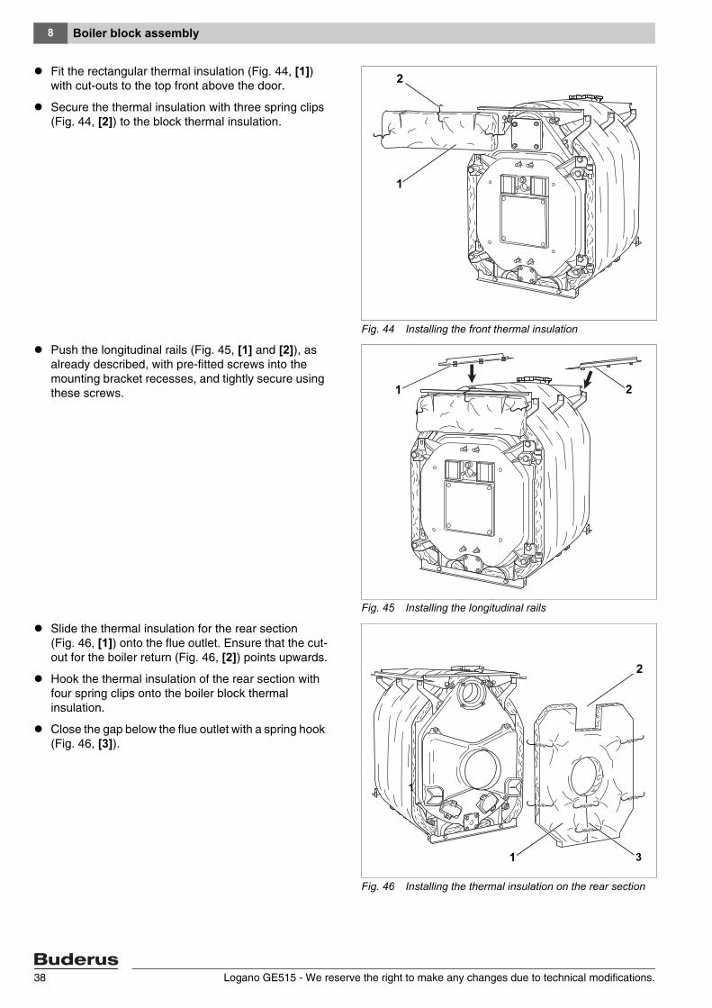
Fit the rectangular thermal insulation (Fig. 44, [1]) with cut-outs to the top front above the door.
Secure the thermal insulation with three spring clips (Fig. 44, [2]) to the block thermal insulation.
Push the longitudinal rails (Fig. 45, [1] and [2]), as already described, with pre-fitted screws into the mounting bracket recesses, and tightly secure using these screws.
Slide the thermal insulation for the rear section (Fig. 46, [1]) onto the flue outlet. Ensure that the cut-out for the boiler return (Fig. 46, [2]) points upwards.
Hook the thermal insulation of the rear section with four spring clips onto the boiler block thermal insulation.
Close the gap below the flue outlet with a spring hook (Fig. 46, [3]).
Fig. 44 Installing the front thermal insulation
1
2
Fig. 45 Installing the longitudinal rails
1 2
Fig. 46 Installing the thermal insulation on the rear section
3
1
1
2
Logano GE515 - We reserve the right to make any changes due to technical modifications.38
Boiler block assembly 8
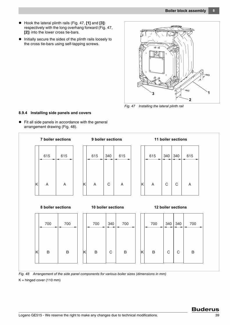
Hook the lateral plinth rails (Fig. 47, [1] and [3]) respectively with the long overhang forward (Fig. 47, [2]) into the lower cross tie-bars.
Initially secure the sides of the plinth rails loosely to the cross tie-bars using self-tapping screws.
8.9.4 Installing side panels and covers
Fit all side panels in accordance with the general arrangement drawing (Fig. 48).
Fig. 47 Installing the lateral plinth rail
132
Fig. 48 Arrangement of the side panel components for various boiler sizes (dimensions in mm)
K = hinged cover (110 mm)
7 boiler sections
8 boiler sections 12 boiler sections10 boiler sections
11 boiler sections9 boiler sections
Logano GE515 - We reserve the right to make any changes due to technical modifications. 39
Boiler block assembly8
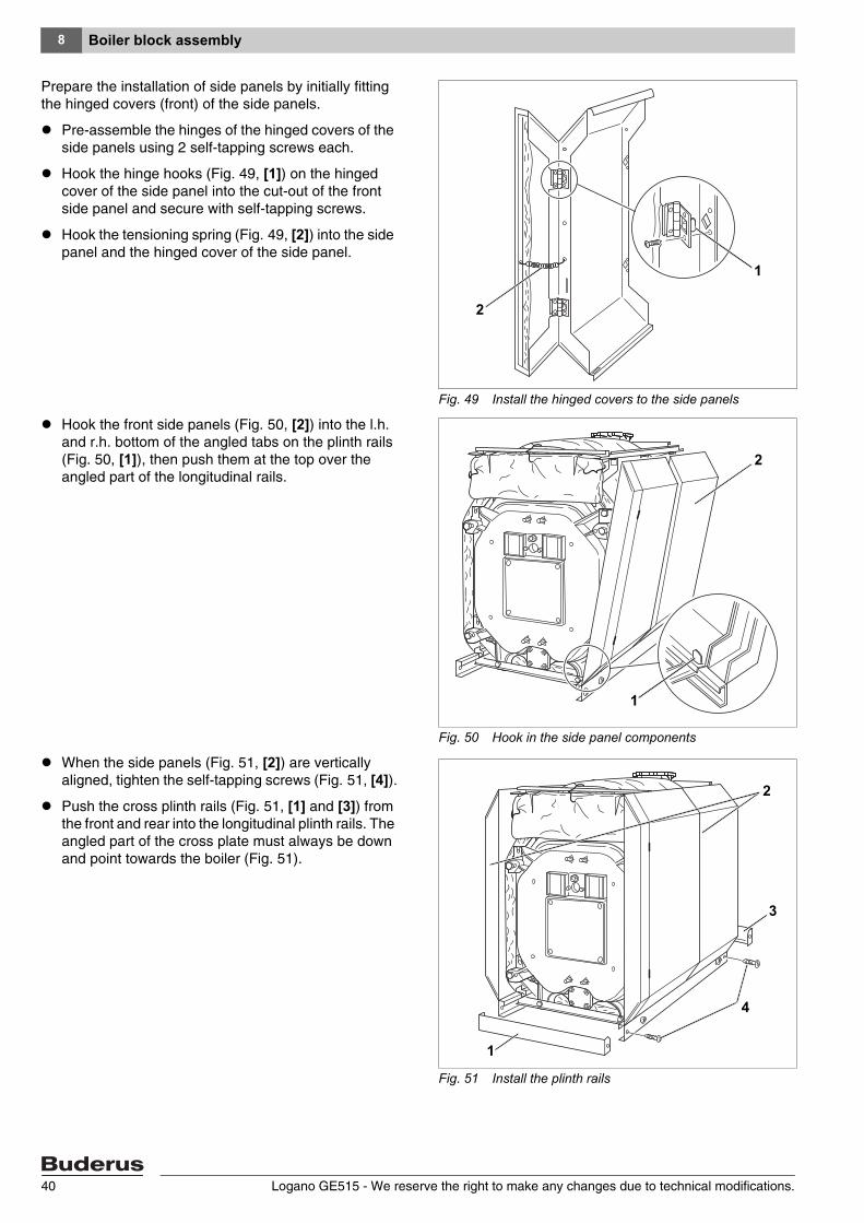
Prepare the installation of side panels by initially fitting the hinged covers (front) of the side panels.
Pre-assemble the hinges of the hinged covers of the side panels using 2 self-tapping screws each.
Hook the hinge hooks (Fig. 49, [1]) on the hinged cover of the side panel into the cut-out of the front side panel and secure with self-tapping screws.
Hook the tensioning spring (Fig. 49, [2]) into the side panel and the hinged cover of the side panel.
Hook the front side panels (Fig. 50, [2]) into the l.h. and r.h. bottom of the angled tabs on the plinth rails (Fig. 50, [1]), then push them at the top over the angled part of the longitudinal rails.
When the side panels (Fig. 51, [2]) are vertically aligned, tighten the self-tapping screws (Fig. 51, [4]).
Push the cross plinth rails (Fig. 51, [1] and [3]) from the front and rear into the longitudinal plinth rails. The angled part of the cross plate must always be down and point towards the boiler (Fig. 51).
Fig. 49 Install the hinged covers to the side panels
1
2
1
2
Fig. 50 Hook in the side panel components
2
1
Fig. 51 Install the plinth rails
1
2
4
3
Logano GE515 - We reserve the right to make any changes due to technical modifications.40
Boiler block assembly 8
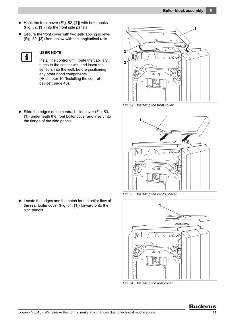
Hook the front cover (Fig. 52, [1]) with both hooks (Fig. 52, [3]) into the front side panels.
Secure the front cover with two self-tapping screws (Fig. 52, [2]) from below with the longitudinal rails.
Slide the edges of the central boiler cover (Fig. 53, [1]) underneath the front boiler cover and insert into the flange of the side panels.
Locate the edges and the notch for the boiler flow of the rear boiler cover (Fig. 54, [1]) forward onto the side panels.
Fig. 52 Installing the front cover
1
2
3USER NOTE
Install the control unit, route the capillary tubes to the sensor well and insert the sensors into the well, before positioning any other hood components ( chapter 10 "Installing the control device", page 46).
Fig. 53 Installing the central cover
2
1
1
Fig. 54 Installing the rear cover
2
1
1
Logano GE515 - We reserve the right to make any changes due to technical modifications. 41
Boiler block assembly8
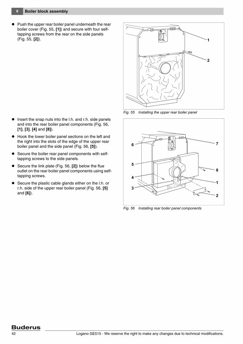
Push the upper rear boiler panel underneath the rear boiler cover (Fig. 55, [1]) and secure with four self-tapping screws from the rear on the side panels (Fig. 55, [2]).
Insert the snap nuts into the l.h. and r.h. side panels and into the rear boiler panel components (Fig. 56, [1], [3], [4] and [8]).
Hook the lower boiler panel sections on the left and the right into the slots of the edge of the upper rear boiler panel and the side panel (Fig. 56, [5]).
Secure the boiler rear panel components with self-tapping screws to the side panels.
Secure the link plate (Fig. 56, [2]) below the flue outlet on the rear boiler panel components using self-tapping screws.
Secure the plastic cable glands either on the l.h. or r.h. side of the upper rear boiler panel (Fig. 56, [5] and [6]).
Fig. 55 Installing the upper rear boiler panel
1
2
Fig. 56 Installing rear boiler panel components
1
2
3
76
5
4
8
Logano GE515 - We reserve the right to make any changes due to technical modifications.42
Boiler block assembly 8
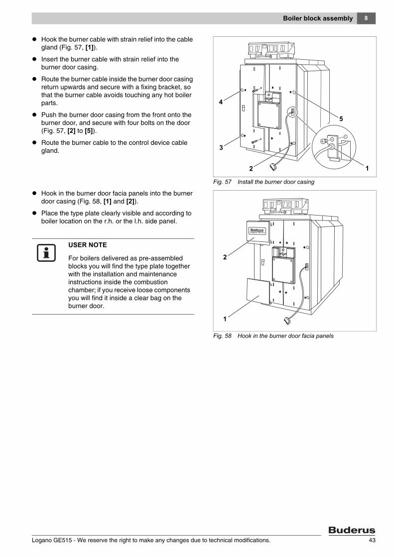
Hook the burner cable with strain relief into the cable gland (Fig. 57, [1]).
Insert the burner cable with strain relief into the burner door casing.
Route the burner cable inside the burner door casing return upwards and secure with a fixing bracket, so that the burner cable avoids touching any hot boiler parts.
Push the burner door casing from the front onto the burner door, and secure with four bolts on the door (Fig. 57, [2] to [5]).
Route the burner cable to the control device cable gland.
Hook in the burner door facia panels into the burner door casing (Fig. 58, [1] and [2]).
Place the type plate clearly visible and according to boiler location on the r.h. or the l.h. side panel.
Fig. 57 Install the burner door casing
5
12
3
4
Fig. 58 Hook in the burner door facia panels
2
1
USER NOTE
For boilers delivered as pre-assembled blocks you will find the type plate together with the installation and maintenance instructions inside the combustion chamber; if you receive loose components you will find it inside a clear bag on the burner door.
Logano GE515 - We reserve the right to make any changes due to technical modifications. 43
Boiler flue connection9
9 Boiler flue connection
This chapter informs you of how you make the boiler flue connections.
9.1 Fit the flue pipe sealing collar (accessory)
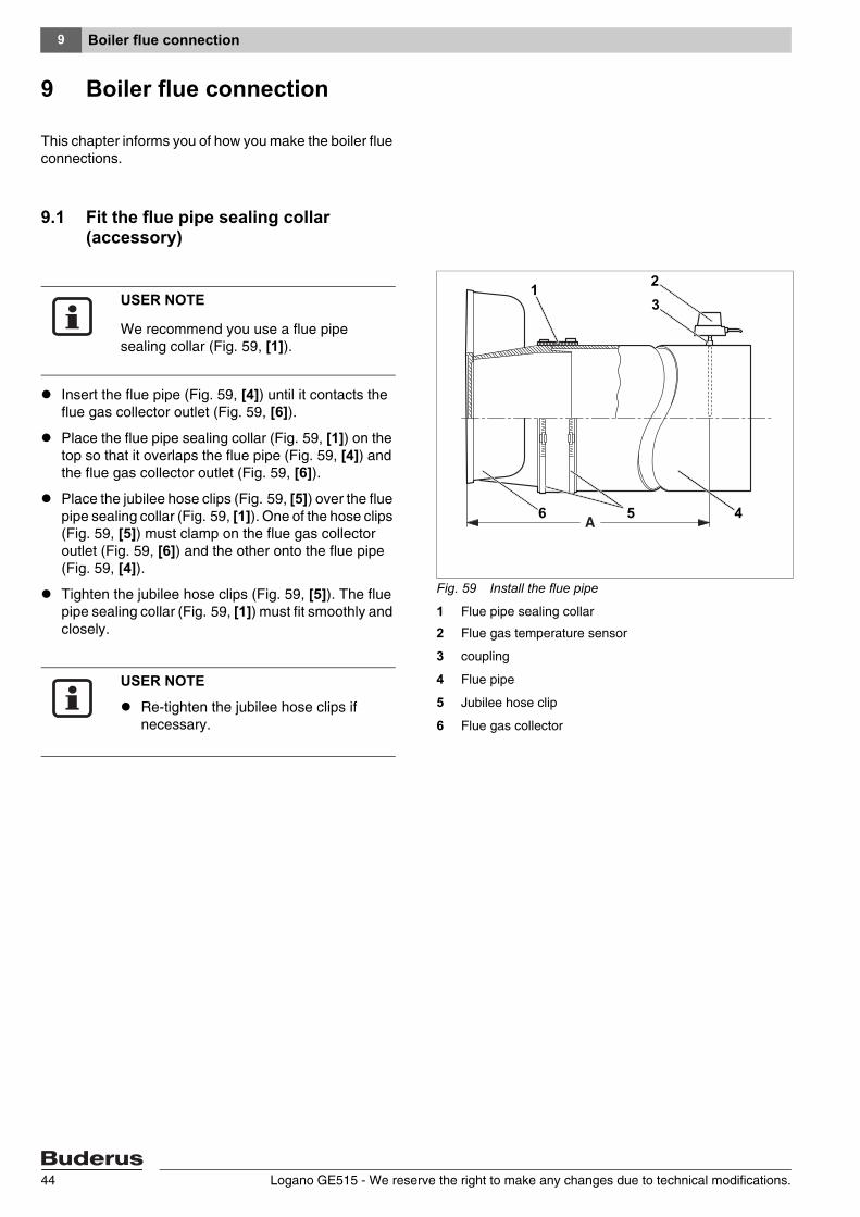
Insert the flue pipe (Fig. 59, [4]) until it contacts the flue gas collector outlet (Fig. 59, [6]).
Place the flue pipe sealing collar (Fig. 59, [1]) on the top so that it overlaps the flue pipe (Fig. 59, [4]) and the flue gas collector outlet (Fig. 59, [6]).
Place the jubilee hose clips (Fig. 59, [5]) over the flue pipe sealing collar (Fig. 59, [1]). One of the hose clips (Fig. 59, [5]) must clamp on the flue gas collector outlet (Fig. 59, [6]) and the other onto the flue pipe (Fig. 59, [4]).
Tighten the jubilee hose clips (Fig. 59, [5]). The flue pipe sealing collar (Fig. 59, [1]) must fit smoothly and closely.
Fig. 59 Install the flue pipe
1 Flue pipe sealing collar
2 Flue gas temperature sensor
3 coupling
4 Flue pipe
5 Jubilee hose clip
6 Flue gas collector
1 23
5 46
USER NOTE
We recommend you use a flue pipe sealing collar (Fig. 59, [1]).
USER NOTE
Re-tighten the jubilee hose clips if necessary.
Logano GE515 - We reserve the right to make any changes due to technical modifications.44
Boiler flue connection 9
9.2 Fitting the flue gas temperature sensor (accessory)
Weld the coupler (Fig. 59, [3]) at a distance of 2 x flue pipe diameter (A) from the flue gas collector (Fig. 59, [6]) into the flue pipe (Fig. 59, [4]).
Install the flue gas temperature sensor (Fig. 59, [2]) in accordance with disconnect installation instructions.
Logano GE515 - We reserve the right to make any changes due to technical modifications. 45
Installing the control device10
10 Installing the control device
This chapter explains how to install a series 4000 control device, plus a temperature sensor set.
10.1 Installing the control device
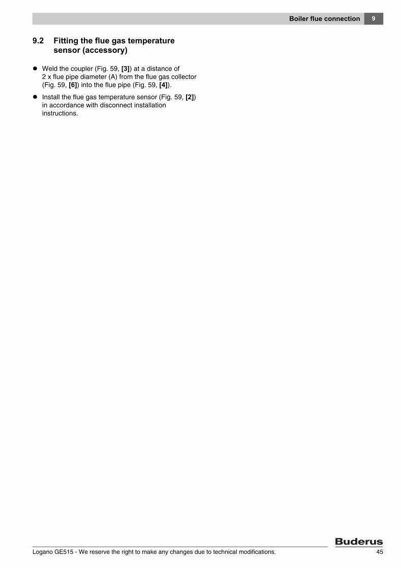
Figure 60 shows the control unit and the front cover "A" as viewed from the rear.
Loosen both screws (Fig. 60, [1]) securing the terminal cover. Remove the terminal cover by pulling it upwards.
Mount the control unit. Insert the control unit at the front of the boiler with the locating tabs (Fig. 60, [4]) into the oval apertures of the front boiler hood (Fig. 60, [5]). Pull the control unit forward and then pivot it back. Ensure that the resilient hooks (Fig. 60, [2]) engage at the rear into the rectangular apertures of the front boiler hood (Fig. 60, [3]).
Secure the control unit base on the r.h. and l.h. side of the cable way (Fig. 60, [6]) in the front boiler hood with two self-tapping screws (Fig. 60, [7]).
Fig. 60 Installing the control device
1
2
456 37
Logano GE515 - We reserve the right to make any changes due to technical modifications.46

Installing the control device 10
10.2 Installing the temperature sensor set and burner cable
Where necessary remove any knockouts (Fig. 61, [1]) in the back of the cable duct (Logamatic 33xx) or from the rear wall (Logamatic 43xx) (Fig. 61, [2]).
Insert the capillary pipes through the cable gland and unroll to the required length.
The sensor well has already been sealed into the flow connection coupler (see chapter 8.5 "Seal-in the sensor well", page 27).
The temperature sensor set (three sensors, one sensor blank Fig. 62, [1]) connected to the control unit is fitted into the R ¾" sensor well.
Route the capillary sensor to the measuring point on the boiler and insert it into the sensor well as far as it will go (Fig. 62, [2]); then secure the assembly with a sensor securing device (Fig. 62, [3]).
Fig. 61 Prepare the cable duct
2
1
USER NOTE
Observe the following when connecting the control device:
Carefully route the cable ducts and capillary pipes.
Never kink capillary pipes during installation.
Work on heating systems must only be carried out by qualified personnel. If you are not suitably qualified, let an electrical contractor carry out the electrical connections.
Observe all local regulations.
Fig. 62 Install the temperature sensor set
1 2
1
2
3
Logano GE515 - We reserve the right to make any changes due to technical modifications. 47
Installing the control device10
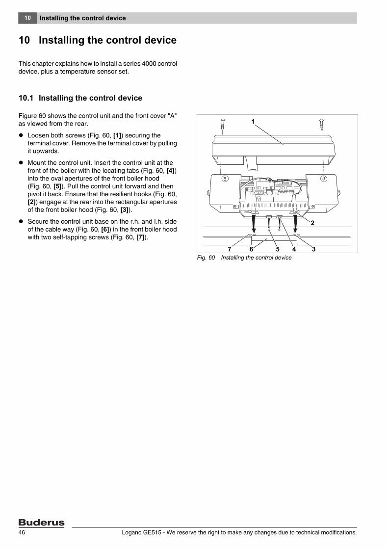
Secure the cable duct (Fig. 63, [1] and [2]) on the l.h. and r.h. side to the rear of the boiler.
Provide a permanent connection acc. to EN 50165 or in accordance with the relevant national regulations.
Make all electrical connections in accordance with the wiring diagram. Pay particular attention to the cable and capillary pipe runs!
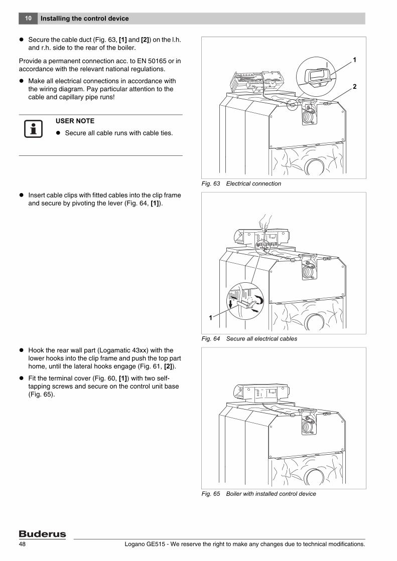
Insert cable clips with fitted cables into the clip frame and secure by pivoting the lever (Fig. 64, [1]).
Hook the rear wall part (Logamatic 43xx) with the lower hooks into the clip frame and push the top part home, until the lateral hooks engage (Fig. 61, [2]).
Fit the terminal cover (Fig. 60, [1]) with two self-tapping screws and secure on the control unit base (Fig. 65).
Fig. 63 Electrical connection
2
1
USER NOTE
Secure all cable runs with cable ties.
Fig. 64 Secure all electrical cables
1 2
1
Fig. 65 Boiler with installed control device
Logano GE515 - We reserve the right to make any changes due to technical modifications.48
Burner installation 11
Logano GE515 - We reserve the right to make any changes due to technical modifications. 49
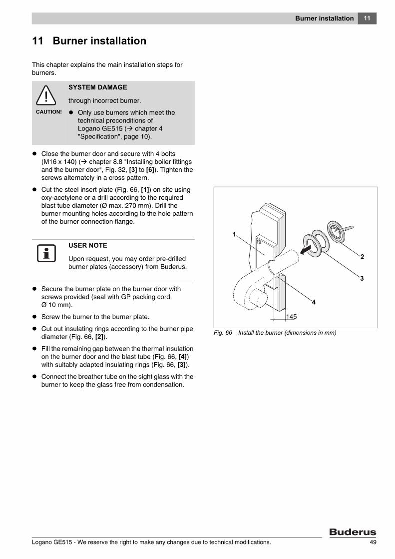
11 Burner installation
This chapter explains the main installation steps for burners.
Close the burner door and secure with 4 bolts (M16 x 140) ( chapter 8.8 "Installing boiler fittings and the burner door", Fig. 32, [3] to [6]). Tighten the screws alternately in a cross pattern.
Cut the steel insert plate (Fig. 66, [1]) on site using oxy-acetylene or a drill according to the required blast tube diameter (Ø max. 270 mm). Drill the burner mounting holes according to the hole pattern of the burner connection flange.
Secure the burner plate on the burner door with screws provided (seal with GP packing cord Ø 10 mm).
Screw the burner to the burner plate.
Cut out insulating rings according to the burner pipe diameter (Fig. 66, [2]).
Fill the remaining gap between the thermal insulation on the burner door and the blast tube (Fig. 66, [4]) with suitably adapted insulating rings (Fig. 66, [3]).
Connect the breather tube on the sight glass with the burner to keep the glass free from condensation.
CAUTION!
SYSTEM DAMAGE
through incorrect burner.
Only use burners which meet the technical preconditions of Logano GE515 ( chapter 4 "Specification", page 10).
Fig. 66 Install the burner (dimensions in mm)
1
2
3
4
USER NOTE
Upon request, you may order pre-drilled burner plates (accessory) from Buderus.
System start-up12
12 System start-up
You can connect series 4000 control devices to Logano GE515 boilers. These control devices are commissioned through identical steps.
Complete the commissioning report ( chapter 12.6 "Commissioning report", page 54).
12.1 Filling the system
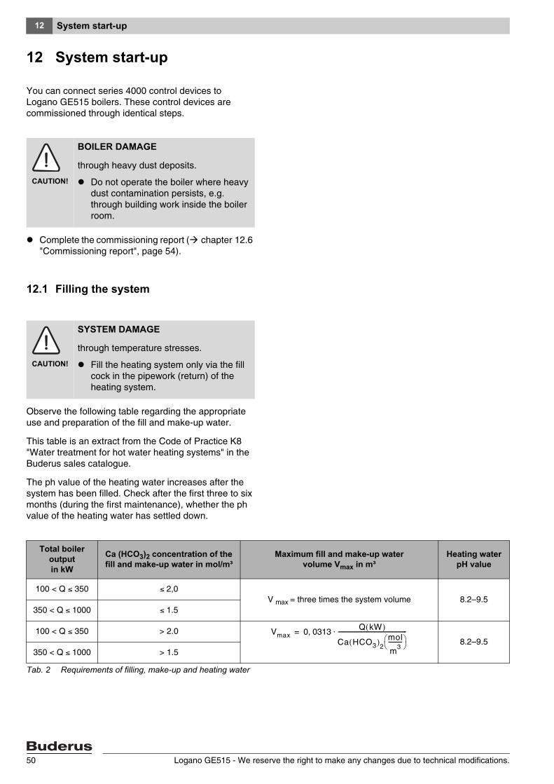
Observe the following table regarding the appropriate use and preparation of the fill and make-up water.
This table is an extract from the Code of Practice K8 "Water treatment for hot water heating systems" in the Buderus sales catalogue.
The ph value of the heating water increases after the system has been filled. Check after the first three to six months (during the first maintenance), whether the ph value of the heating water has settled down.
CAUTION!
BOILER DAMAGE
through heavy dust deposits.
Do not operate the boiler where heavy dust contamination persists, e.g. through building work inside the boiler room.
CAUTION!
SYSTEM DAMAGE
through temperature stresses.
Fill the heating system only via the fill cock in the pipework (return) of the heating system.
Total boiler outputin kW
Ca (HCO3)2 concentration of the fill and make-up water in mol/m³
Maximum fill and make-up water volume Vmax in m³
Heating water pH value
100 < Q ≤ 350 ≤ 2,0V max = three times the system volume 8.2–9.5
350 < Q ≤ 1000 ≤ 1.5
100 < Q ≤ 350 > 2.08.2–9.5
350 < Q ≤ 1000 > 1.5
Tab. 2 Requirements of filling, make-up and heating water
Vmax 0 0313 Q kW( )
Ca HCO3( )2
mol
m3
----------⎝ ⎠⎛ ⎞
-------------------------------------------------⋅,=
Logano GE515 - We reserve the right to make any changes due to technical modifications.50
System start-up 12
12.2 Making the system operational
Observe the following during commissioning:
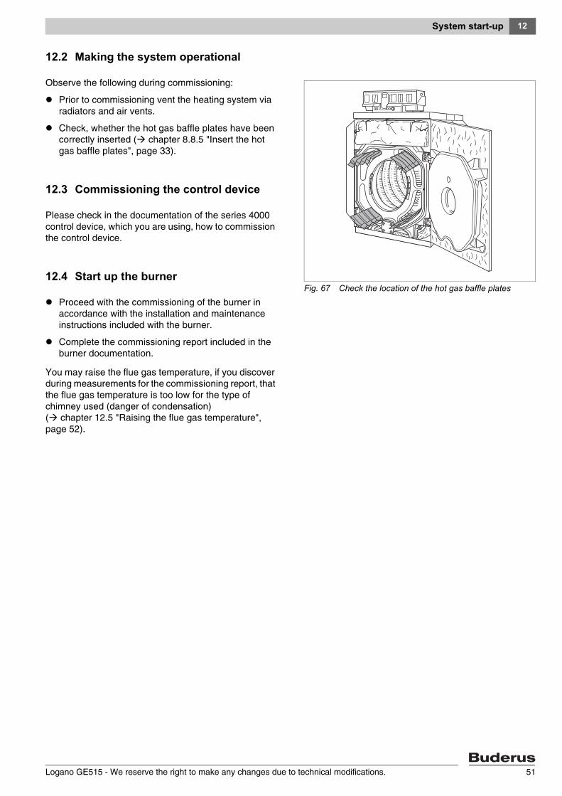
Prior to commissioning vent the heating system via radiators and air vents.
Check, whether the hot gas baffle plates have been correctly inserted ( chapter 8.8.5 "Insert the hot gas baffle plates", page 33).
12.3 Commissioning the control device
Please check in the documentation of the series 4000 control device, which you are using, how to commission the control device.
12.4 Start up the burner
Proceed with the commissioning of the burner in accordance with the installation and maintenance instructions included with the burner.
Complete the commissioning report included in the burner documentation.
You may raise the flue gas temperature, if you discover during measurements for the commissioning report, that the flue gas temperature is too low for the type of chimney used (danger of condensation) ( chapter 12.5 "Raising the flue gas temperature", page 52).
Fig. 67 Check the location of the hot gas baffle plates
Logano GE515 - We reserve the right to make any changes due to technical modifications. 51

System start-up12
12.5 Raising the flue gas temperature
Depending on boiler size and setup (related to the rated output), the flue gas temperature of a new boiler with a boiler water temperature of 80 °C is approx. 160 –180 °C.
The flue gas temperature is correspondingly lower in a two stage operation.
If necessary, you may increase the flue gas temperature further by individually removing hot gas check plates or hot gas baffle plates.
Shut down the boiler in accordance with operating instructions.
The flue gas temperature can be raised through the following measures.
12.5.1 Removing hot gas baffle plates
For boiler size 7–11 (240–455 kW), the flue gas temperature can be raised by removing top or bottom hot gas baffle plates in pairs.
12.5.2 Removing hot gas check plates
You can significantly raise the flue gas temperature by removing hot gas check plates.
Remove the Allen screws inside each hot gas check plate and remove the l.h. and r.h. hot gas check plates (Fig. 68, [1] and [2]).
USER NOTE
When taking these steps you should consider changes in the hot gas check plates as a last option, since a reduction in the size of the hot gas check plates is irreversible.
Fig. 68 Location of the hot gas check plates
1
2
Logano GE515 - We reserve the right to make any changes due to technical modifications.52
System start-up 12
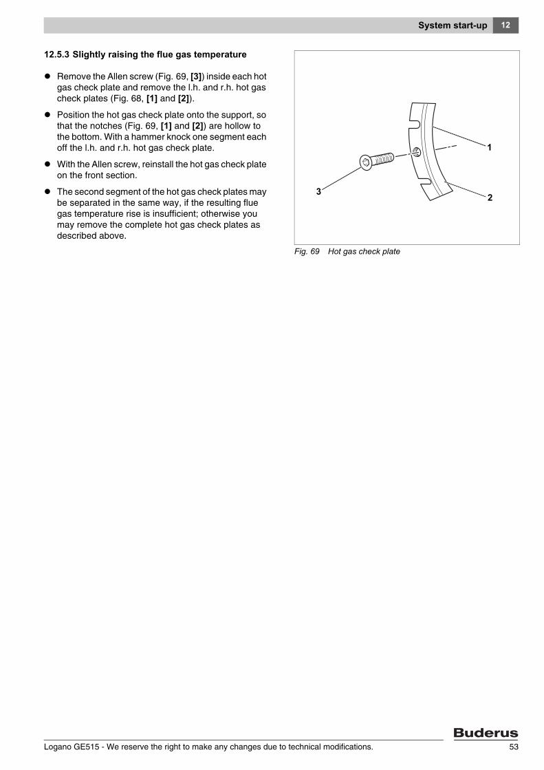
12.5.3 Slightly raising the flue gas temperature
Remove the Allen screw (Fig. 69, [3]) inside each hot gas check plate and remove the l.h. and r.h. hot gas check plates (Fig. 68, [1] and [2]).
Position the hot gas check plate onto the support, so that the notches (Fig. 69, [1] and [2]) are hollow to the bottom. With a hammer knock one segment each off the l.h. and r.h. hot gas check plate.
With the Allen screw, reinstall the hot gas check plate on the front section.
The second segment of the hot gas check plates may be separated in the same way, if the resulting flue gas temperature rise is insufficient; otherwise you may remove the complete hot gas check plates as described above.
Fig. 69 Hot gas check plate
1
23
Logano GE515 - We reserve the right to make any changes due to technical modifications. 53
System start-up12
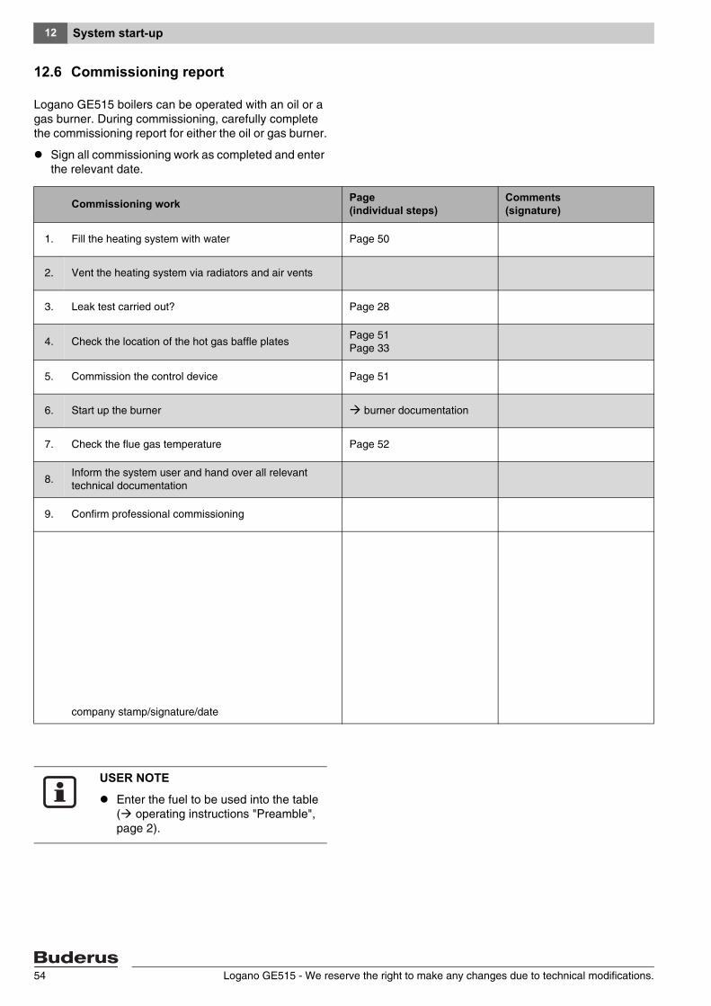
12.6 Commissioning report
Logano GE515 boilers can be operated with an oil or a gas burner. During commissioning, carefully complete the commissioning report for either the oil or gas burner.
Sign all commissioning work as completed and enter the relevant date.
Commissioning work Page (individual steps)
Comments (signature)
1. Fill the heating system with water Page 50
2. Vent the heating system via radiators and air vents
3. Leak test carried out? Page 28
4. Check the location of the hot gas baffle platesPage 51 Page 33
5. Commission the control device Page 51
6. Start up the burner burner documentation
7. Check the flue gas temperature Page 52
8.Inform the system user and hand over all relevant technical documentation
9. Confirm professional commissioning
company stamp/signature/date
USER NOTE
Enter the fuel to be used into the table ( operating instructions "Preamble", page 2).
Logano GE515 - We reserve the right to make any changes due to technical modifications.54

System shutdown 13
Logano GE515 - We reserve the right to make any changes due to technical modifications. 55
13 System shutdown
You can connect control devices series 4000 to Logano GE515 boilers. These control devices are shut down through identical steps.
13.1 Shutting down the system via the control device
Shut down your boiler via the control device. The burner is automatically shut down when the system is shut down via the control device.
Isolate the main fuel valve.
13.2 Shutting down the system in an emergency
In other dangerous circumstances, isolate the main fuel shut-off valve and the electrical power supply of the system via the boiler room main fuse or the emergency stop switch for the boiler room.
Isolate the main fuel valve.
CAUTION!
SYSTEM DAMAGE
through frost.
The heating system can freeze up if it is not in use, e.g. through a shut-down because of fault(s).
Protect your heating system against frost damage, where temperatures below zero are expected. Drain the heating water at the drain cock at the lowest point in the system. To do this, open the air vent valve at the highest point in the system.
USER NOTE
Only in an emergency, switch off the system via the boiler room fuse or heating system emergency stop switch.
System inspection and maintenance14
14 System inspection and maintenance
14.1 General notes
Offer an annual inspection and maintenance contract (depending on requirements) to your customer. You can check under chapter 14.6 "Inspection and maintenance reports", page 63 what is required for an annual inspection and demand-dependent maintenance contract.
14.2 Why is regular maintenance important?
You should service your client's system for the following reasons:
– to achieve a high level of efficiency and to operate the system economically (low fuel consumption),
– to achieve a high level of operational reliability,
– to maintain the highest level of environmentally responsible combustion.
WARNUNG!
DANGER TO LIFE
through the explosion of volatile gases.
Work on gas components must only be carried out by qualified and authorised personnel.
USER NOTE
You may order spare parts from the Buderus spare parts catalogue.
Logano GE515 - We reserve the right to make any changes due to technical modifications.56
System inspection and maintenance 14
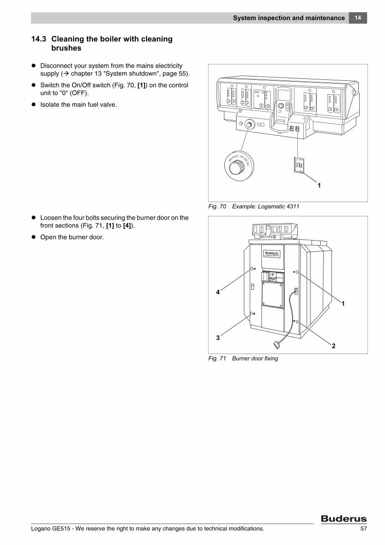
14.3 Cleaning the boiler with cleaning brushes
Disconnect your system from the mains electricity supply ( chapter 13 "System shutdown", page 55).
Switch the On/Off switch (Fig. 70, [1]) on the control unit to "0" (OFF).
Isolate the main fuel valve.
Loosen the four bolts securing the burner door on the front sections (Fig. 71, [1] to [4]).
Open the burner door.
Fig. 70 Example: Logamatic 4311
1
Fig. 71 Burner door fixing
4
1
23
Logano GE515 - We reserve the right to make any changes due to technical modifications. 57
System inspection and maintenance14
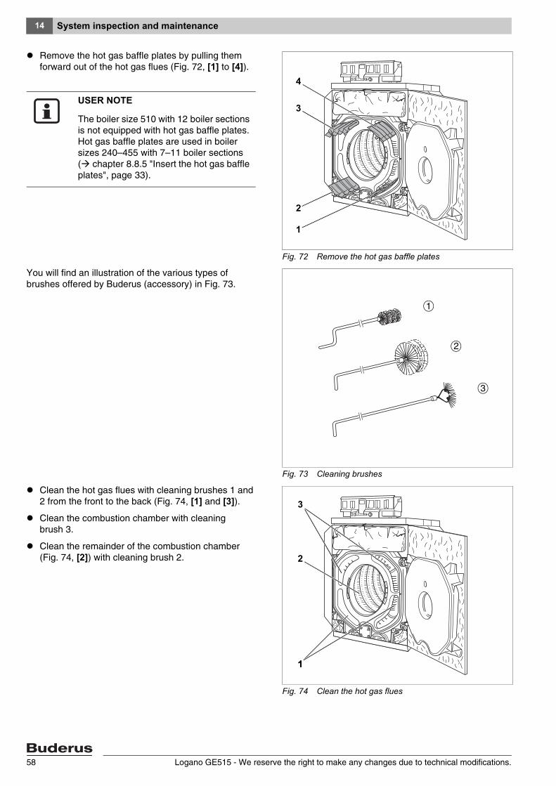
Remove the hot gas baffle plates by pulling them forward out of the hot gas flues (Fig. 72, [1] to [4]).
You will find an illustration of the various types of brushes offered by Buderus (accessory) in Fig. 73.
Clean the hot gas flues with cleaning brushes 1 and 2 from the front to the back (Fig. 74, [1] and [3]).
Clean the combustion chamber with cleaning brush 3.
Clean the remainder of the combustion chamber (Fig. 74, [2]) with cleaning brush 2.
Fig. 72 Remove the hot gas baffle plates
1
2
3
4
USER NOTE
The boiler size 510 with 12 boiler sections is not equipped with hot gas baffle plates. Hot gas baffle plates are used in boiler sizes 240–455 with 7–11 boiler sections ( chapter 8.8.5 "Insert the hot gas baffle plates", page 33).
Fig. 73 Cleaning brushes
1
3
2
Fig. 74 Clean the hot gas flues
3
1
2
1
Logano GE515 - We reserve the right to make any changes due to technical modifications.58
System inspection and maintenance 14
Slacken both self-tapping screws on the connection plate and remove the plate.
Remove both self-tapping screws on the l.h. and r.h. side of the boiler rear panel section.
Slightly lift the lower rear boiler panel section and remove towards the back.
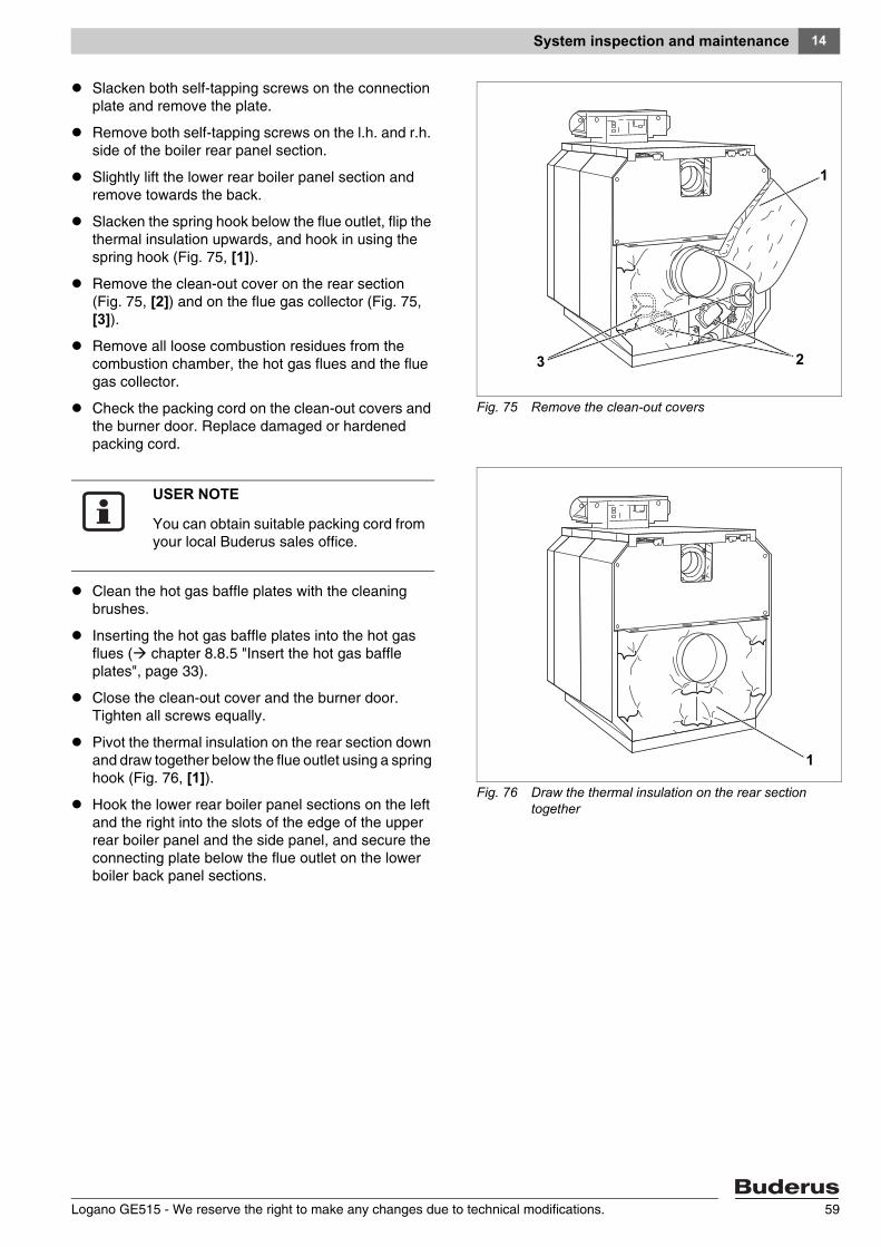
Slacken the spring hook below the flue outlet, flip the thermal insulation upwards, and hook in using the spring hook (Fig. 75, [1]).
Remove the clean-out cover on the rear section (Fig. 75, [2]) and on the flue gas collector (Fig. 75, [3]).
Remove all loose combustion residues from the combustion chamber, the hot gas flues and the flue gas collector.
Check the packing cord on the clean-out covers and the burner door. Replace damaged or hardened packing cord.
Clean the hot gas baffle plates with the cleaning brushes.
Inserting the hot gas baffle plates into the hot gas flues ( chapter 8.8.5 "Insert the hot gas baffle plates", page 33).
Close the clean-out cover and the burner door. Tighten all screws equally.
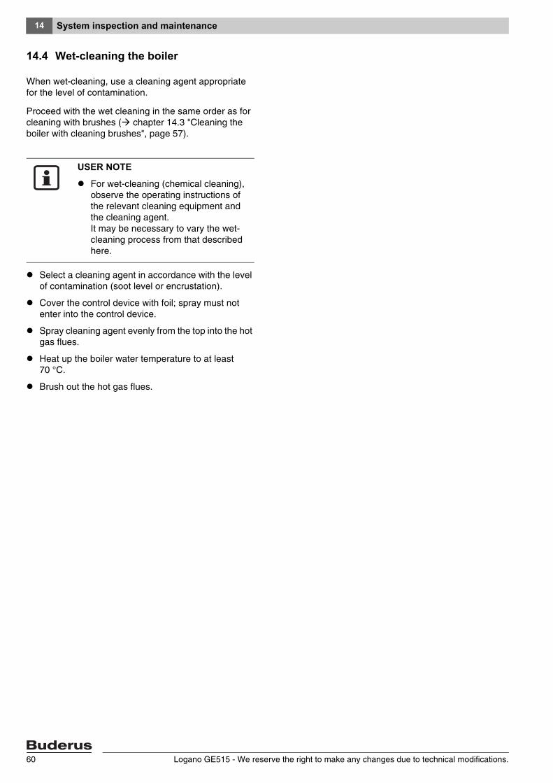
Pivot the thermal insulation on the rear section down and draw together below the flue outlet using a spring hook (Fig. 76, [1]).
Hook the lower rear boiler panel sections on the left and the right into the slots of the edge of the upper rear boiler panel and the side panel, and secure the connecting plate below the flue outlet on the lower boiler back panel sections.
Fig. 75 Remove the clean-out covers
1
23
Fig. 76 Draw the thermal insulation on the rear section together
1
USER NOTE
You can obtain suitable packing cord from your local Buderus sales office.
Logano GE515 - We reserve the right to make any changes due to technical modifications. 59
System inspection and maintenance14
14.4 Wet-cleaning the boiler
When wet-cleaning, use a cleaning agent appropriate for the level of contamination.
Proceed with the wet cleaning in the same order as for cleaning with brushes ( chapter 14.3 "Cleaning the boiler with cleaning brushes", page 57).
Select a cleaning agent in accordance with the level of contamination (soot level or encrustation).
Cover the control device with foil; spray must not enter into the control device.
Spray cleaning agent evenly from the top into the hot gas flues.
Heat up the boiler water temperature to at least 70 °C.
Brush out the hot gas flues.
USER NOTE
For wet-cleaning (chemical cleaning), observe the operating instructions of the relevant cleaning equipment and the cleaning agent. It may be necessary to vary the wet-cleaning process from that described here.
Logano GE515 - We reserve the right to make any changes due to technical modifications.60
System inspection and maintenance 14
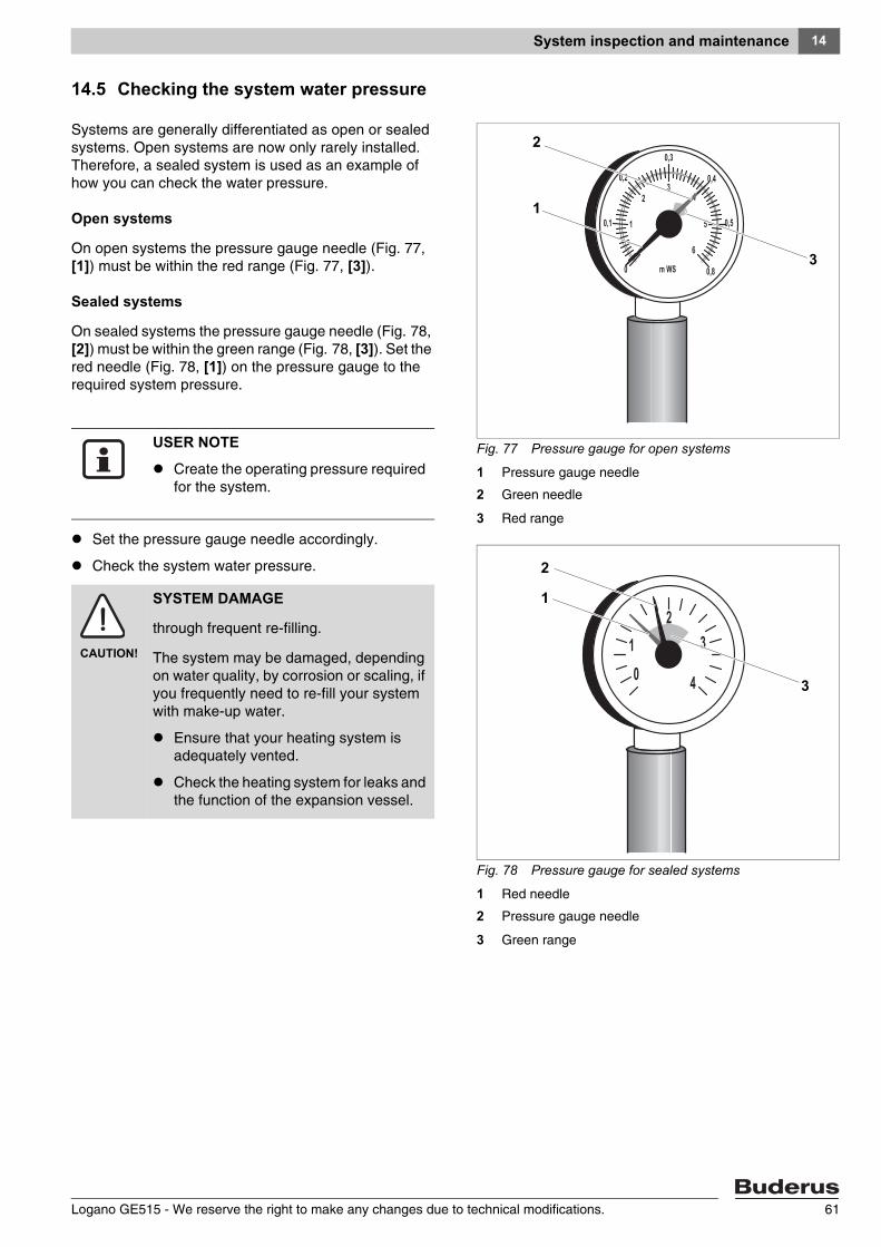
14.5 Checking the system water pressure
Systems are generally differentiated as open or sealed systems. Open systems are now only rarely installed. Therefore, a sealed system is used as an example of how you can check the water pressure.
Open systems
On open systems the pressure gauge needle (Fig. 77, [1]) must be within the red range (Fig. 77, [3]).
Sealed systems
On sealed systems the pressure gauge needle (Fig. 78, [2]) must be within the green range (Fig. 78, [3]). Set the red needle (Fig. 78, [1]) on the pressure gauge to the required system pressure.
Set the pressure gauge needle accordingly.
Check the system water pressure.
Fig. 77 Pressure gauge for open systems
1 Pressure gauge needle
2 Green needle
3 Red range
Fig. 78 Pressure gauge for sealed systems
1 Red needle
2 Pressure gauge needle
3 Green range
3
1
2
3
1
2
USER NOTE
Create the operating pressure required for the system.
CAUTION!
SYSTEM DAMAGE
through frequent re-filling.
The system may be damaged, depending on water quality, by corrosion or scaling, if you frequently need to re-fill your system with make-up water.
Ensure that your heating system is adequately vented.
Check the heating system for leaks and the function of the expansion vessel.
Logano GE515 - We reserve the right to make any changes due to technical modifications. 61
System inspection and maintenance14
The water pressure in the system is too low, if the pressure gauge needle falls below (Fig. 78, [2]) the green range (Fig. 78, [3]). You then need to re-fill the heating system with make-up water ( chapter 12.1 "Filling the system", page 50).
Fill make-up water through the fill tap in the heating system pipework (return).
Vent the heating system.
Check the water pressure once more.
CAUTION!
SYSTEM DAMAGE
through temperature stresses.
Never fill the heating system during operation via the KFE tap on the boiler. Instead use only the fill tap in the pipework (return) of the heating system.
Logano GE515 - We reserve the right to make any changes due to technical modifications.62
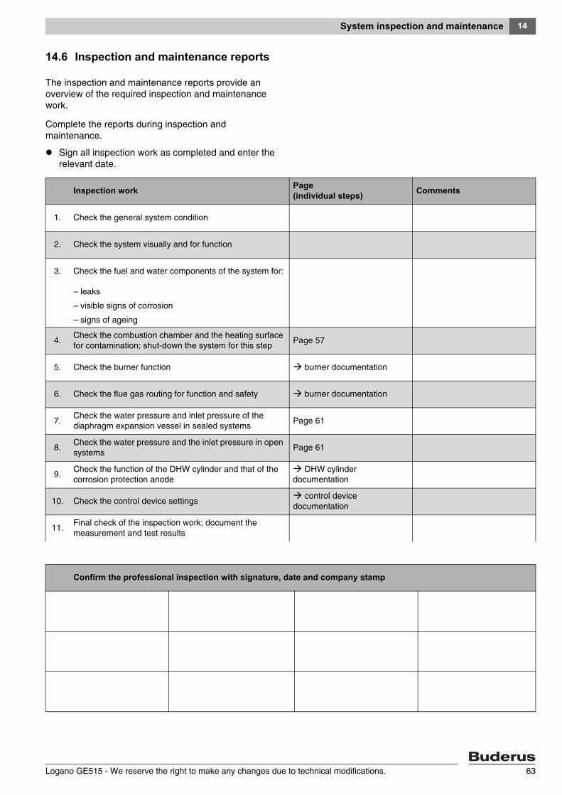
System inspection and maintenance 14
14.6 Inspection and maintenance reports
The inspection and maintenance reports provide an overview of the required inspection and maintenance work.
Complete the reports during inspection and maintenance.
Sign all inspection work as completed and enter the relevant date.
Inspection work Page (individual steps) Comments
1. Check the general system condition
2. Check the system visually and for function
3. Check the fuel and water components of the system for:
– leaks
– visible signs of corrosion
– signs of ageing
4.Check the combustion chamber and the heating surface for contamination; shut-down the system for this step
Page 57
5. Check the burner function burner documentation
6. Check the flue gas routing for function and safety burner documentation
7.Check the water pressure and inlet pressure of the diaphragm expansion vessel in sealed systems
Page 61
8.Check the water pressure and the inlet pressure in open systems
Page 61
9.Check the function of the DHW cylinder and that of the corrosion protection anode
DHW cylinder documentation
10. Check the control device settings control device
documentation
11.Final check of the inspection work; document the measurement and test results
Confirm the professional inspection with signature, date and company stamp
Logano GE515 - We reserve the right to make any changes due to technical modifications. 63
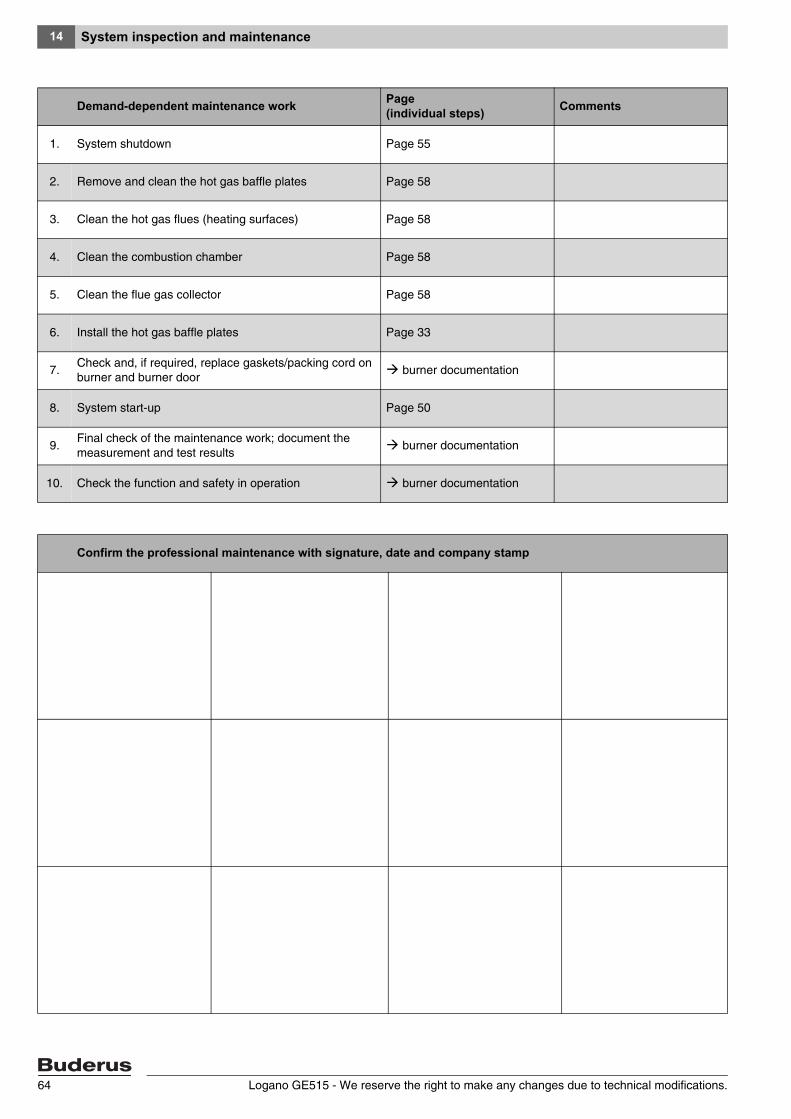
System inspection and maintenance14
Demand-dependent maintenance work Page (individual steps) Comments
1. System shutdown Page 55
2. Remove and clean the hot gas baffle plates Page 58
3. Clean the hot gas flues (heating surfaces) Page 58
4. Clean the combustion chamber Page 58
5. Clean the flue gas collector Page 58
6. Install the hot gas baffle plates Page 33
7.Check and, if required, replace gaskets/packing cord on burner and burner door
burner documentation
8. System start-up Page 50
9.Final check of the maintenance work; document the measurement and test results
burner documentation
10. Check the function and safety in operation burner documentation
Confirm the professional maintenance with signature, date and company stamp
Logano GE515 - We reserve the right to make any changes due to technical modifications.64
Correcting burner faults 15
Logano GE515 - We reserve the right to make any changes due to technical modifications. 65
15 Correcting burner faults
Heating system faults are indicated in the control device display. You will find detailed information regarding fault displays in the service instructions of each respective control device. In addition any burner fault is indicated by a fault lamp on the burner.
Press the burner reset button ( burner operating instructions).
See the technical burner documentation for information regarding the resetting of the burner, if the burner will not start after three attempts.
CAUTION!
SYSTEM DAMAGE
through frequent activation of the reset button.
The burner ignition transformer may be damaged if you press the reset button more than three times in succession after the burner refuses to start.
Do not attempt to clear a fault more than three times in succession by using the reset button.
Index16
Logano GE515 - We reserve the right to make any changes due to technical modifications.66
16 Index
BBoiler block . . . . . . . . . . . . . . . . . . . . . 26
Boiler compression tool . . . . . . . . . . . . . . . 15
Boiler operating conditions . . . . . . . . . . . . . 5Boiler sections . . . . . . . . . . . . . . . . . . .10
Boiler size . . . . . . . . . . . . . . . . . . .10, 11
Boiler water content . . . . . . . . . . . . . . . . 10
Burner . . . . . . . . . . . . . . . . . . . . . . .49
CCasing . . . . . . . . . . . . . . . . . . . . . . .39
Centre section . . . . . . . . . . . . . . . . . . .22
Cleaning brushes . . . . . . . . . . . . . . . . . . 58
Clean-out cover . . . . . . . . . . . . . . . . . . . 19
CO2 content . . . . . . . . . . . . . . . . . . . .11
Combustion output . . . . . . . . . . . . . . . . .10
Compression tool . . . . . . . . . . . . . . . . . . 15
Connection flanges . . . . . . . . . . . . . . . . . 30
Control thermostat . . . . . . . . . . . . . . . . . 5
Control unit . . . . . . . . . . . . . . . . . . . . . 8
DDepth of burner door . . . . . . . . . . . . . . . .10
Diameter of burner chamber . . . . . . . . . . . . 10
Draught . . . . . . . . . . . . . . . . . . . . . . .11
FFeed pipe . . . . . . . . . . . . . . . . . . . . . . 27
Fill water . . . . . . . . . . . . . . . . . . . . . .50
Flow temperature . . . . . . . . . . . . . . . . 5, 11
Flue gas collector . . . . . . . . . . . . . . . . . . 31
Flue gas mass flow rate . . . . . . . . . . . . . . 11
Flue gas resistance . . . . . . . . . . . . . . . . . 11
Flue gas temperature . . . . . . . . . . . . . . . . 11
Flue pipe . . . . . . . . . . . . . . . . . . . . . . 44
Fuel . . . . . . . . . . . . . . . . . . . . . . . . . 5
GGas capacity . . . . . . . . . . . . . . . . . . . . 10
HHot gas baffle plates . . . . . . . . . . . . . . . .33
Hot gas check plates . . . . . . . . . . . . . . . .33
IInspection contract . . . . . . . . . . . . . . . . 56
Installation template . . . . . . . . . . . . . . . . 19
LLeak test . . . . . . . . . . . . . . . . . . . . . 28
Length of boiler block . . . . . . . . . . . . . . . 10
Length of burner chamber . . . . . . . . . . . . 10
MMake-up water . . . . . . . . . . . . . . . . . . 50
Maximum operating pressure . . . . . . . . . . . . 5
OOperating pressure . . . . . . . . . . . . . . . . 11
Overall boiler length . . . . . . . . . . . . . . . . 10
PProduct description . . . . . . . . . . . . . . . . . 8
RRated output . . . . . . . . . . . . . . . . . . . 10
Rear section . . . . . . . . . . . . . . . . . . . 19
Rear wall components - boiler . . . . . . . . . . 42
SSensor well . . . . . . . . . . . . . . . . . . . . 27
Service contract (as required) . . . . . . . . . . 56
Specification . . . . . . . . . . . . . . . . . . . 10
TThermal insulation . . . . . . . . . . . . . . . 8, 36
Thermal insulation - rear section . . . . . . . . . 38
Transport . . . . . . . . . . . . . . . . . . . . . 13
Transportation . . . . . . . . . . . . . . . . . . 10
WWeight . . . . . . . . . . . . . . . . . . . . . . 10

Notes
Logano GE515 - We reserve the right to make any changes due to technical modifications. 67

BuderusCotswold Way, Warndon, Worcester WR4 9SWCustomer service: 0870 421 5933Technical support: 0870 421 5944Fax: 01905 753130www.buderus-commercial.co.uk
In the UK and IE, Buderus is a brand name of Bosch Thermotechnology Ltd.