Embed Size (px)
Citation preview

BOILERBOILERBOILERBOILER
“BOILER” MEANS ANY CLOSED VESSEL EXCEEDING 22.75 Litres IN CAPACITYWHICH IS USED FOR GENERATING STEAM UNDER PRESSURE. - IBR

Boiler Codes have been written by various nations in the past century to ensure safety of personnel and to avoid loss of property. Boiler codes cover the whole gamut of activities including Design, Fabrication, Testing, Construction and Operation.The various aspects of IBR Regulations are called out and consolidated against major items like drum, headers, lines & links, etc. The following codes have been used widely.
BOILER CODESBOILER CODES
1. IBR 19502. ASME Section-I3. BS 11134. DIN TRD 300.

1. UTILITY Boilers are large capacity steam generators
used purely for electrical power generation.
2. INDUSTRIAL Boilers are small capacity boilers
intended for use in the process industries.
TYPES OF BOILERSTYPES OF BOILERS
(A) BASED ON) BASED ON APPLICATIONAPPLICATION :

1. Vertical Package- VP
2. Vertical Recovery-V2R
3. Vertical Unit 40-VU40
4. Vertical Unit 60-VU60
5. Modular Unit-MU
6. 2 Pass Single Arch
7. 2 Pass Double Arch
8. Close couple
9. Box Type
10.Tower Type
(B) BASED ON CONSTRUCTIONBASED ON CONSTRUCTION::
Types of Boilers…….contdTypes of Boilers…….contd

1. OIL FIRED
2. OIL AND COAL FIRED
3. BLACK LIQUOR (For Paper Mills)
4. BAGGASE (Stoker Fired)
Types of Boilers…….contdTypes of Boilers…….contd
(C) BASED ONBASED ON FUEL:FUEL:
1.WALL FIRING
2.CORNER TANGENTIAL FIRING
3.STOKER
Types of Boilers…….contdTypes of Boilers…….contd
(D) BASED ONBASED ON TYPE OF FIRING:TYPE OF FIRING:

1.SINGLE DRUM
2.BI- DRUM
3.NO DRUM (Vertical Separator)
Types of Boilers…….contdTypes of Boilers…….contd
(E) BASED ONBASED ON NO. OF DRUMSNO. OF DRUMS:

1. NATURAL
2.1 FORCED Circulation (Pump)
2.2 CONTROLLED Circulation (+Orifice)
2.3 CC+ (Pump + Orifice + Rifled Tubing)
3. Once Through
(F) BASED ONBASED ON CIRCULATIONCIRCULATION:
Types of Boilers…….contdTypes of Boilers…….contd
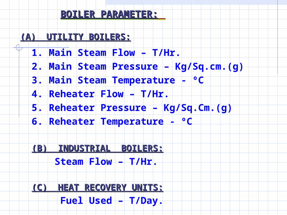
1. Main Steam Flow – T/Hr.
2. Main Steam Pressure – Kg/Sq.cm.(g)
3. Main Steam Temperature - ºC
4. Reheater Flow – T/Hr.
5. Reheater Pressure – Kg/Sq.Cm.(g)
6. Reheater Temperature - ºC
(B) INDUSTRIAL BOILERS:(B) INDUSTRIAL BOILERS:
Steam Flow – T/Hr.
(C) HEAT RECOVERY UNITS:(C) HEAT RECOVERY UNITS:
Fuel Used – T/Day.
BOILER PARAMETER:BOILER PARAMETER: BOILER PARAMETER:BOILER PARAMETER:
(A) UTILITY BOILERS:(A) UTILITY BOILERS:
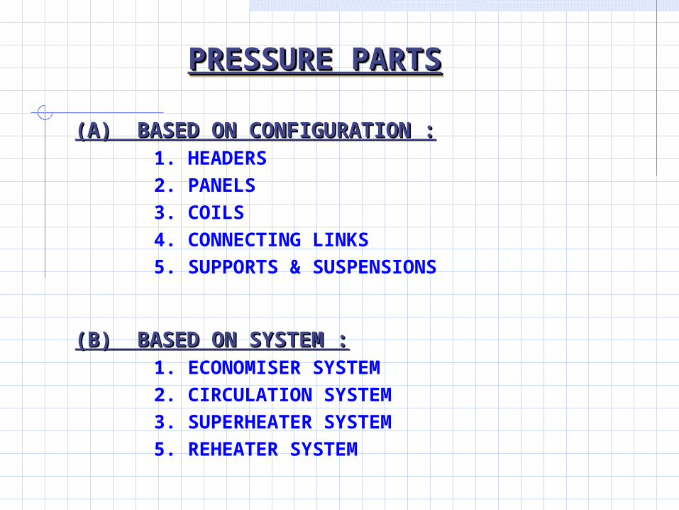
PRESSURE PARTSPRESSURE PARTSPRESSURE PARTSPRESSURE PARTS
(A) BASED ON CONFIGURATION :(A) BASED ON CONFIGURATION : 1. HEADERS
2. PANELS
3. COILS
4. CONNECTING LINKS
5. SUPPORTS & SUSPENSIONS
(B) BASED ON SYSTEM :(B) BASED ON SYSTEM : 1. ECONOMISER SYSTEM
2. CIRCULATION SYSTEM
3. SUPERHEATER SYSTEM
5. REHEATER SYSTEM

PRESSURE PARTS PRESSURE PARTS
PERFORMANCE PARAMETERS:PERFORMANCE PARAMETERS:
1. SIZE (Diameter)
2. SIZE (Thickness)
3. MATERIAL (Specification)
4. TRANSVERSE SPACING (ST)
5. LONGITUDINAL SPACING (SL)
6. HEATING SURFACE AREA
7. No. OF ELEMENTS
8. No. OF ASSEMBLIES
(WITH RESPECT TO ARRANGEMENT)

9. INLET / OUTLET CONNECTION REQUIREMENTS
10. FURNACE WIDTH
11. FURNACE DEPTH
12. EXTENDED PASS DEPTH
13. BACKPASS DEPTH
14. HOPPER ANGLE
15. ARCH CONFIGURATION
16. COIL / BANK DEPTH
Pressure Parts ..…contd

DETAIL DESIGN REQUIREMENTS:DETAIL DESIGN REQUIREMENTS:
• IBR REQUIREMENT (Strength Calculations)
• MANUFACTURING REQUIREMENTS
• HEAT TREATMENT REQUIREMENTS
• TRANSPORT LIMITATIONS (ODC)
Pressure Parts ..…contd

• GUIDES ,SUPPORTS & SUSPENSIONS
• THERMAL EXPANSION
• FLEXIBILITY OF COMPONENTS
• DISTANCE OF TOP HEADERS ABOVE ROOF
• BUCKSTAY SPACING
Pressure Parts ..…contd
STRESS ANALYSIS REQUIREMENTS:STRESS ANALYSIS REQUIREMENTS:

•INTERFERANCE FREE ARRGT./ ROUTING OF
RISERS / PIPES / LINKS
•WELD ACCESSIBILITY
•TAKING CARE OF LAYOUT REQUIREMENTS (Ex.
Matching Components
•TAKING CARE OF PERFORMANCE, DETAIL DESIGN &
STRESS ANALYSIS ASPECTS
Pressure Parts ..…contd
ARRANGEMENT REQUIREMENTS:ARRANGEMENT REQUIREMENTS:

DRUM AND DRUM INTERNALS: DRUM AND DRUM INTERNALS:
CIRCULATION SYSTEM: CIRCULATION SYSTEM:
The circulation system of water through the furnace
water wall is due to either natural circulation or controlled
circulation.
Natural circulation boilers employ the effect of
density differences between water and steam to produce
circulation.
At higher pressures and height of the boiler where
density difference is not adequate the difference is
augmented by a pump effecting Controlled circulation.

DRUMDRUM
To provide space for separation of steam from steam
water mixture.
To house the internals required for steam separation
such as Feed water distribution system, Turbo
separators, Separating chamber, Screen driers etc.

To provide a water storage for preventing the starvation
of tubes during operation. Drum diameter and length should be sufficient to
provide accessibility for installation and inspection. Thickness of drum is determined to meet the stresses induced due to internal pressure, self weight and external loads.

DRUM INTERNALS:DRUM INTERNALS:
Separation of water from steam water mixture.
Removal of bubbles entering into the downcomer which will affect the density of fluid and circulation by providing vortex breakers.
Mixing and distributing the feed water.
Adding chemicals.
Facilitating blow down.

FURNACE / BACK PASS WALLS:FURNACE / BACK PASS WALLS:
Normally for boiler furnace enclosures membrane wall
construction (fusion welded panels) is adopted in
place of tangent tube construction which is not leak
proof and increased erection work.
Back pass enclosures are formed by fin welded panels
with wider pitch because the flue gas temperature is
less compared to furnace.

These heating surfaces are in the form of coils which are made by bending the tubes in cold or hot condition. The superheater is composed of four basic sections.
The platen section is located directly above the furnace in front of the furnace arch. It absorbs heat mainly by radiation. The pendant spaced section is located in back of the screen wall tubes. The mode of heat transfer is convection.
The horizontal section of the superheater is located in the rear gas pass above economiser. The steam cooled wall sections form the side, front and rear walls and roof of the vertical gas pass.
SUPERHEATER AND REHEATER:SUPERHEATER AND REHEATER:

Desuperheaters:Desuperheaters:
Desuperheating - Steam temperature control.
Provided in
1.superheater connecting links
2.cold reheat line
to permit reduction of steam temperature when necessary
to maintain the temperatures
The desuperheaters used in the reheater system is
meant for emergency condition.
The reheat steam temperature is controlled mainly by
tilting burners.

Reheater Reheater
The reheater - Single stage – 2 Sections
Front & rear pendant vertical spaced.
The front section located between the rear water wall
hanger tubes and the superheater platen section.
The rear section is located between water wall
screen and rear wall hanger tubes.

Spacer are used to maintain pitches along and across
coil assemblies.
1.Transverse spacers and alignment ties.
2.
Fluid cooled spacers or mechanical spacer bar are used as transverse spacers
.
3.
Flexible connector and alignment bands are used as alignment ties. to maintain pitch between tubes in the same assembly
.
SPACERS FOR SH & RH:SPACERS FOR SH & RH:

SUPPORTS & SUSPENSIONS FOR SH & RH:
1.Vertical Assemblies are suspended from the ceiling. 2.In pendant assemblies the tie lugs are welded in between tubes at the top row to transfer the load from centre to end terminals.3.The horizontal superheaters are supported by economiser hanger tubes through strap supports.4.The pendant coils are suspended by high crown supports. The high crown plates are welded on either side of seal band and the load is transferred through end bar. 5.The headers will be independently supported from the ceiling through tie rod assemblies with or without variable spring hangers as the case may be.


Pressure Parts Arrangement Comparison ofPressure Parts Arrangement Comparison of 250 MW and 500 MW Boilers250 MW and 500 MW Boilers
Circulation
Circulating Pump
Down comer Connections
Lower Ring header with Orifice Plates
Divisional Panellette Super Heater
Extended Pass
Split Extended pass
Steam Cooled side wall for Extended Pass Steam Cooled Eco. / LTSH Hangers Rifled Tubings in WaterWalls Wall Reheater (Presently not followed)


RECENT CHANGES IN 500MWRECENT CHANGES IN 500MW RECENT CHANGES IN 500MWRECENT CHANGES IN 500MW
TO MEET THE REQUIREMENT OF PERFORMANCE THE
FOLLOWING MODIFICATIONS ARE CARRIED OUT IN
SOME OF OUR BOILERS:
• TWIN REHEATER OUTLET HEADERS
• DESUPER HEATER CRISS-CROSS LOCATION
CHANGED FROM LTSH OUTLET TO DIVISIONAL
PANEL OUTLET
• WALL SUPER HEATER ADDITION IN VINDHYACHAL
• WALL REHEATER REMOVAL
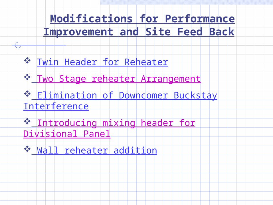
Modifications for Performance Improvement and Site Feed Back
Twin Header for Reheater
Two Stage reheater Arrangement
Elimination of Downcomer Buckstay Interference
Introducing mixing header for Divisional Panel
Wall reheater addition

EXISTING ARRANGMENT
RH INLET HEADER RH OUTLET HEADER
ROOF ELEVATION
FLOW
FLOW FLOW
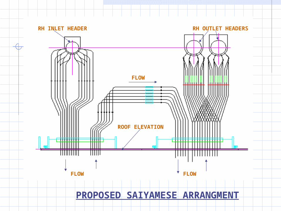
RH INLET HEADER RH OUTLET HEADERS
ROOF ELEVATION
PROPOSED SAIYAMESE ARRANGMENT
FLOW
FLOW FLOW

RIHAND & RAMAGUNADAM REHEATER OUTLET HEADER NIPPLE ARRGMT.
TO AVOID LEFT TO RIGHT TEMPERATURE UNBALANCE

Divided Back pass and Horizontal Coils
• Back pass depth 9144 and 9144 mm
• Back pass width = 23926.8 mm (Equal to Furnace Width)
• Steam cooled center wall (fin welded panel) divides the back pass
• Radial Distributor supplies steam to all back pass walls
• All coils are supported by steam cooled hangers
• LTRH coils placed in the first partition and LTSH in the second partition
• Eco first Stage in first Partition; Eco second stage in second partition below LTRH and LTSH coil banks respectively
• Flue gas biasing dampers are placed below eco inlet headers

Steam Cooled Spacer

Spacer Lug

Alignment b
and

BACK

BACK

BACK

BACK

BACK

Sl. No.
Description MaterialDesign Temp. °C
1.Economiser
CoilsSA 210 Gr A1
326
Headers
SA 106 Gr C 398
Economiser System
Circulating System
Sl. No.
Description MaterialDesign Temp. °C
1. Drum SA 299 368
2.Waterwalls
TubesSA210 Gr C
398
Headers
SA 299, SA106 Gr C
370
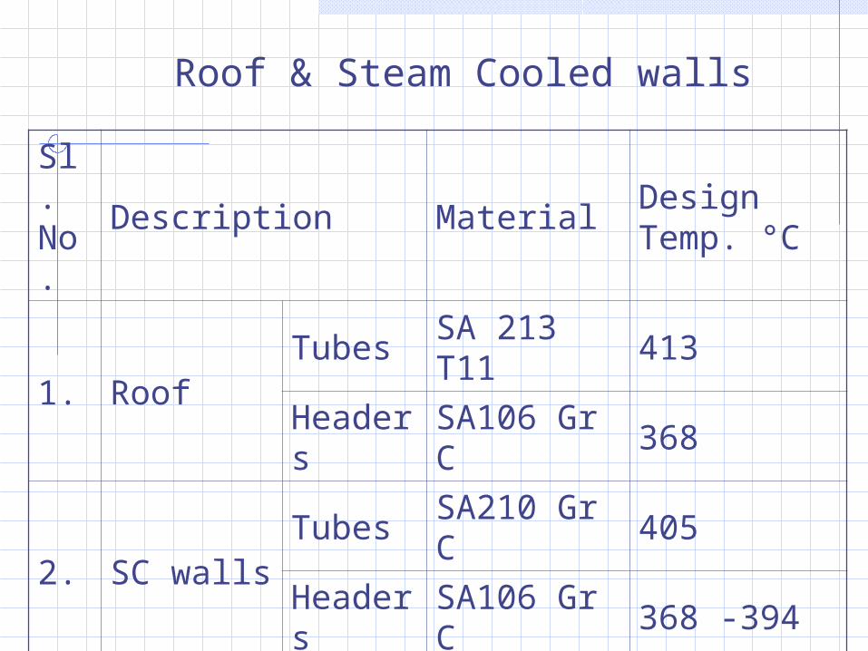
Roof & Steam Cooled walls
Sl. No.
Description MaterialDesign Temp. °C
1. RoofTubes
SA 213 T11
413
Headers
SA106 Gr C
368
2. SC wallsTubes
SA210 Gr C
405
Headers
SA106 Gr C
368 -394
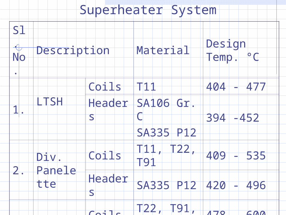
Sl. No.
Description MaterialDesign Temp. °C
1.LTSH
Coils T11 404 - 477
Headers
SA106 Gr. CSA335 P12
394 -452
2.Div. Panelette
CoilsT11, T22, T91
409 - 535
Headers
SA335 P12 420 - 496
3. Platen
CoilsT22, T91, TP347H,
478 - 600
Headers
SA335 P12SA335 P22
489 - 572
Superheater System

Sl. No.
Description MaterialDesign Temp. °C
1. RH
CoilsT11, T22, T91, TP347H,
351 - 589
Headers
SA106 Gr CSA335 P22
361 - 590
Reheater System