Embed Size (px)
Citation preview
Land Rover Discovery 3
Ian Bodsworth
Disco3Club.co.uk
July 2010
Version 1.3
© Copyright Ian Bodsworth
Bodsy’s Brake Bible

© Copyright Ian Bodsworth 2010. All descriptions and photo’s contained within remain the property of the Author. Commercial images of products with copyrights acknowledged. E&OE. - Created by Bodsy – D3C Page 2 of 34
Change Record
DATE Revision Update Notes Made By May 2010 1.2 Amended Torque Figures and bolt sizes, cleaned up photo
areas. Updated text. Ian Bodsworth
June 2010 1.2a Re-worded EPB adjust procedure, updated EBP Allen key size. Added Change record
Ian Bodsworth
July 2010 1.3 Updated Tool List, inserted Tool/Job Matrix, added EPB change instructions, added jacking point pics, added Brake Pad Wear Sensor replacement & pics.
Ian Bodsworth

© Copyright Ian Bodsworth 2010. All descriptions and photo’s contained within remain the property of the Author. Commercial images of products with copyrights acknowledged. E&OE. - Created by Bodsy – D3C Page 3 of 34
Table of Contents 1. Introduction ................................................................................................................................................................. 4
2. Tools that may be required ...................................................................................................................................... 5
3. Jacking Points and Axle Stands ............................................................................................................................... 7
4. How to change the Brake Pads - Front ................................................................................................................ 10
5. How to change the Brake Pads – Rear ................................................................................................................. 14
6. How to change the Brake Pad Sensors – Front and Rear ................................................................................ 18
7. How to change the Brake Disks – Front ............................................................................................................... 20
8. How to change the Brake Disks – Rear ................................................................................................................ 23
9. How to adjust the Electronic Park Brake ........................................................................................................... 27
10. How to fit new EPB Shoes ................................................................................................................................... 29
11. How to Bed in new EPB shoes ............................................................................................................................ 32
12. How to replace the brake fluid and Bleed the braking system ................................................................. 33

© Copyright Ian Bodsworth 2010. All descriptions and photo’s contained within remain the property of the Author. Commercial images of products with copyrights acknowledged. E&OE. - Created by Bodsy – D3C Page 4 of 34
1. Introduction
Welcome to Bodsy’s Brake Bible. The aim of this ‘Bible’ is to provide a single area for all
information relating to the servicing and maintenance of your Discovery 3 2,7 TDv6 braking
system. It can be used as a basis for the V6 and V8 Petrol as well as the 3.0l TDv6, but I cannot
guarantee it will be exactly right for those variants as I have not used this on those models. If
you have used this guide on those models and have any updates we could use (inc pics) then
please e-mail them to me and I will update this accordingly.
Please note that these are guidelines only and you should ensure that you are competent in
the use of the tools required and take the necessary safety precautions. If you have any doubt
of your competence, please contact your nearest Land Rover dealer or Land Rover
independent garage who will be pleased to carry out this work for you.
Neither the author nor Disco3Club/Disco4Club can accept any responsibility for any accidents
or injuries sustained whilst undertaking the work depicted in this bible.
All of the photos (unless otherwise indicated) are from my Discovery 3 MY07 TdV6 HSE.
Further technical information is available from Land Rover’s subscription services TOPIx (ex-
GTR) website, which can be found here:-
http://topix.landrover.jlrext.com/topix/vehicle/lookupForm
http://www.landrovertechinfo.com/
I acknowledge the assistance of members of the Disco3.co.uk forum and Land Rover® TOPIx/GTR for the initial guidance and advice before I
commenced this guide which supersedes my previous collection of posts and other information.
© Copyright Ian Bodsworth 2010. All descriptions and photo’s contained within remain the property of the Author. Commercial images of products with copyrights acknowledged. E&OE. - Created by Bodsy – D3C Page 5 of 34
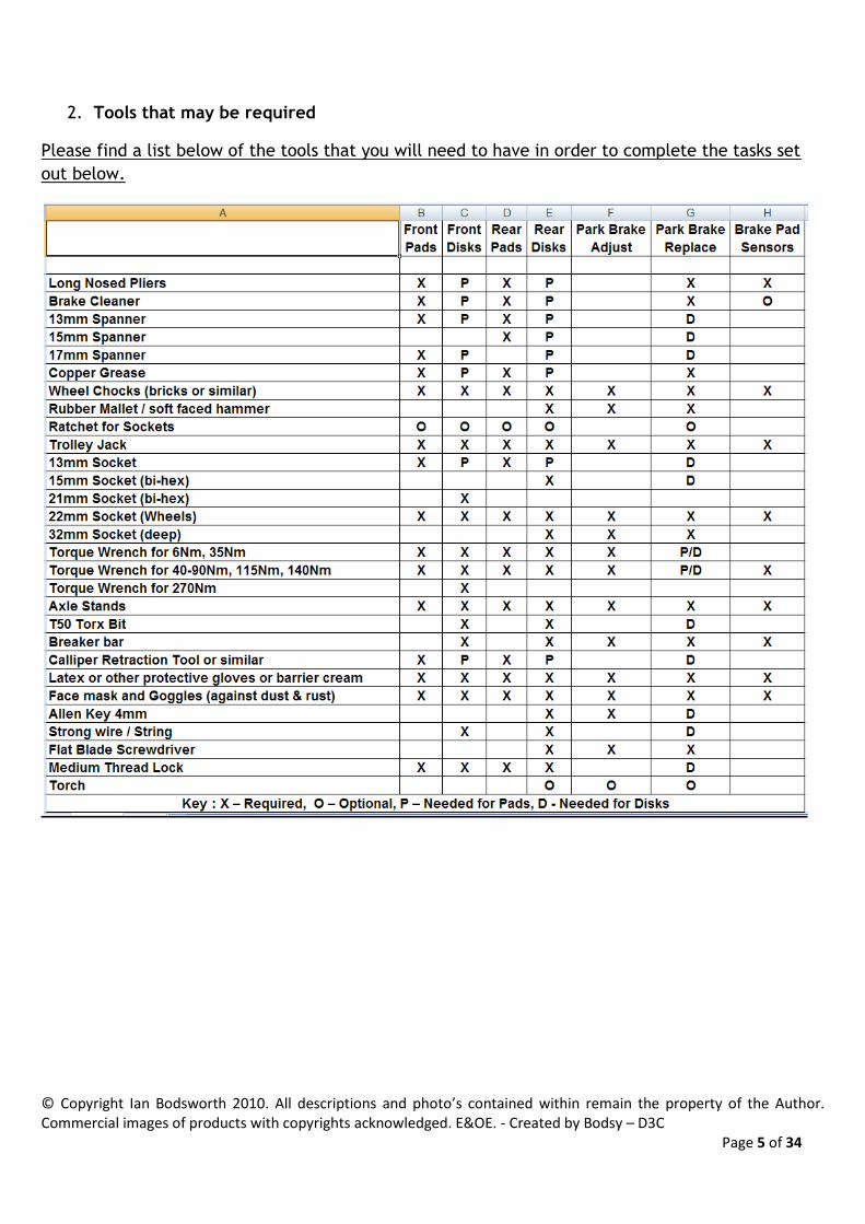
2. Tools that may be required
Please find a list below of the tools that you will need to have in order to complete the tasks set
out below.

© Copyright Ian Bodsworth 2010. All descriptions and photo’s contained within remain the property of the Author. Commercial images of products with copyrights acknowledged. E&OE. - Created by Bodsy – D3C Page 6 of 34
All torque settings contained within this ‘bible’ are manufacturers recommended settings.
Optional additions to the tool kit are:-
1) Regular cups of tea/coffee
2) Box of plasters for grazed knuckles
3) A suitably sized swear box, depending on a combination of a) location b) weather c)
temperature d) ‘help’ by young children/dog/neighbours

© Copyright Ian Bodsworth 2010. All descriptions and photo’s contained within remain the property of the Author. Commercial images of products with copyrights acknowledged. E&OE. - Created by Bodsy – D3C Page 7 of 34
3. Jacking Points and Axle Stands
The standard jack that comes with the Discovery 3 or 4, is widely regarded as ‘not very good’. If you are going
to do any work on your vehicle that requires raising the chassis, then we would recommend that you purchase
or borrow a suitable trolley jack.
The Discovery 3 / 4 weighs in excess of 2.7 tonnes, so you need to ensure that you have a jack that is capable
of supporting both the weight of the vehicle and the height
that is required.
Most hydraulic jacks are suited to standard sized cars. Your
Discovery has a height range that requires a jack ideally
capable of lifting 520mm.
One popular jack is the Clarke CTJ3000G, it is a heavy duty
trolley jack available (at time of creation) at Machine Mart
http://www.machinemart.co.uk/shop/product/details/ctj3000
g-3-tonne-professional-garage-j
Beware, there is also a CTJ3000QL which is a quick lift version
of the above. There have been reports of this model twisting
under load when used on a Discovery 4 or 4.
There are specific jacking points underneath your car, DO NOT JACK ON YOUR AIR SUSPENSION COMPRESSOR
COVER or on the long air compressor tank. You will damage it beyond repair.
Once you have jacked the car up, ensure that you use suitable
axle stands to secure the car.
I have these, rated at 6T (pair) and more than sufficient height
available.
But others are available,
such as these
http://www.machinemart
.co.uk/shop/product/deta
ils/cax-6tbc-6-ton-axle-
stands
Others are available, but
the sturdier the better.

© Copyright Ian Bodsworth 2010. All descriptions and photo’s contained within remain the property of the Author. Commercial images of products with copyrights acknowledged. E&OE. - Created by Bodsy – D3C Page 8 of 34
Ensure that your vehicle is securely supported on axle stands before undertaking any work underneath it.
Ensure that any wheels remaining in contact with the ground are securely chocked to avoid any unnecessary
movement. If removing Wheels, loosen the wheel nuts before jacking off the ground.
WARNING: Always chock the wheels which are not to be raised.
One front wheel - position lifting pad of hydraulic jack beneath longitudinal member on the side to be
raised at Point 'A'
One rear wheel - position lifting pad of jack beneath longitudinal member on the side to be raised at
Point 'B'
Front and rear wheels - ONE SIDE - position lifting pad of jack beneath longitudinal member on the
side to be raised at Point 'C'
NOTE:
Point 'C' is in line with number 3 body mounting.
With vehicle at desired height, position axle stand(s) beneath longitudinal members and adjacent to the lifting
pad of the jack at appropriate point(s) D.
CAUTION: Position suitable material between axle stands and longitudinal members to prevent
© Copyright Ian Bodsworth 2010. All descriptions and photo’s contained within remain the property of the Author. Commercial images of products with copyrights acknowledged. E&OE. - Created by Bodsy – D3C Page 9 of 34
damage to the longitudinal members.
Carefully lower jack until vehicle rests on axle stands.
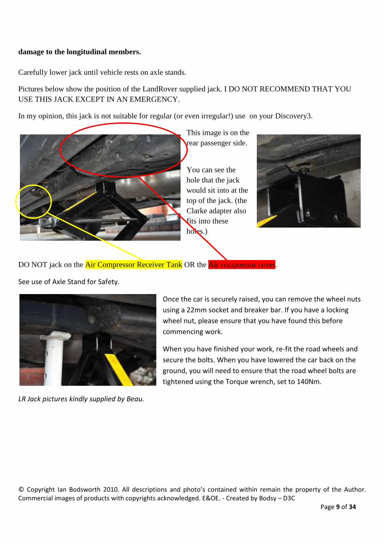
Pictures below show the position of the LandRover supplied jack. I DO NOT RECOMMEND THAT YOU
USE THIS JACK EXCEPT IN AN EMERGENCY.
In my opinion, this jack is not suitable for regular (or even irregular!) use on your Discovery3.
This image is on the
rear passenger side.
You can see the
hole that the jack
would sit into at the
top of the jack. (the
Clarke adapter also
fits into these
holes.)
DO NOT jack on the Air Compressor Receiver Tank OR the Air compressor cover.
See use of Axle Stand for Safety.
Once the car is securely raised, you can remove the wheel nuts
using a 22mm socket and breaker bar. If you have a locking
wheel nut, please ensure that you have found this before
commencing work.
When you have finished your work, re-fit the road wheels and
secure the bolts. When you have lowered the car back on the
ground, you will need to ensure that the road wheel bolts are
tightened using the Torque wrench, set to 140Nm.
LR Jack pictures kindly supplied by Beau.

© Copyright Ian Bodsworth 2010. All descriptions and photo’s contained within remain the property of the Author. Commercial images of products with copyrights acknowledged. E&OE. - Created by Bodsy – D3C Page 10 of 34
4. How to change the Brake Pads - Front
Ensure that your vehicle is securely supported on axle stands before undertaking any work underneath it.
Ensure that any wheels remaining in contact with the ground are securely chocked to avoid any unnecessary
movement.
Change Front Brake Pads (See page 5 for tool matrix)
Pliers
Brake Cleaner
Spanners, 13mm, 17mm
Copper Grease
Optional Ratchet
Socket 13mm
Torque Wrench
The Discovery 3 has a Dual piston calliper brake system for the Front. It relies on hydraulic pressure from the
braking system to push brake Pads onto the rotating Brake Disk. Over time, the Brake pads will wear down,
eventually causing a loud scrapping noise as the brake pad backing plate grinds into the steel disk. If you have
reached this point, then in all likelihood, you will need to replace the Brake disks as well as the pads.
The front Passenger side disk also has a brake wear sensor. If you have NOT broken through this sensor, then
it can be safely re-used. Otherwise you need to ensure you have a replacement at the time of fitting.
Jack the car up (see Axle Stands & Jacking Points) Remove the front road wheels.
Once you have the road wheels removed, then you can remove
the Brake pad wear sensor. (Front Passenger Side)
Use a pair of pliers to carefully extract the sensor. You may find
that the brass contact in the sensor is also removed. Providing
that you don’t lose it or it doesn’t ping off into a deep hidden
crevice, then it should be able to be easily re-fitted.
You should pull the sensor directly backwards until it is
removed.
Here you can see the sensor without the brass contact (which has remained on
the brake pad).
Here you can see the brass contact which needs to be
re-fitted or the whole sensor replaced.
© Copyright Ian Bodsworth 2010. All descriptions and photo’s contained within remain the property of the Author. Commercial images of products with copyrights acknowledged. E&OE. - Created by Bodsy – D3C Page 11 of 34
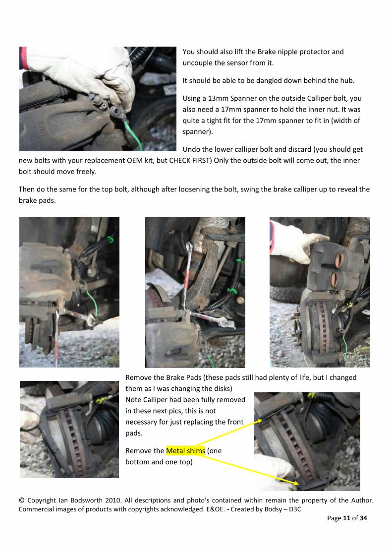
You should also lift the Brake nipple protector and
uncouple the sensor from it.
It should be able to be dangled down behind the hub.
Using a 13mm Spanner on the outside Calliper bolt, you
also need a 17mm spanner to hold the inner nut. It was
quite a tight fit for the 17mm spanner to fit in (width of
spanner).
Undo the lower calliper bolt and discard (you should get
new bolts with your replacement OEM kit, but CHECK FIRST) Only the outside bolt will come out, the inner
bolt should move freely.
Then do the same for the top bolt, although after loosening the bolt, swing the brake calliper up to reveal the
brake pads.
Remove the Brake Pads (these pads still had plenty of life, but I changed
them as I was changing the disks)
Note Calliper had been fully removed
in these next pics, this is not
necessary for just replacing the front
pads.
Remove the Metal shims (one
bottom and one top)

© Copyright Ian Bodsworth 2010. All descriptions and photo’s contained within remain the property of the Author. Commercial images of products with copyrights acknowledged. E&OE. - Created by Bodsy – D3C Page 12 of 34
This is what you should expect from an OE set of Front
Brake Pads.
2 replacement Bolts (the Blue is thread loc)
2 replacement Shims (you can re-use old Shims, but best
to have replacements)
2 OE Brake Pads
Fit the new Shims to the Calliper holder (note new disks had been fitted before
this). The Shims just press on & click into place.
Before fitting the Brake
Pads, ensure you use a
liberal coating of Copper Grease to the top and bottom
lugs of the brake pad to keep the brake pads easily
moving. Applied by tube in
this case.
Re-fit the brake pads with the friction surface facing inwards. Be sure that there is
no grease on the front of the brake pad.
With the brake Calliper, spray plenty of brake cleaner on the calliper and then use
a Calliper Piston Retraction tool or other home made device to retract the brake
callipers into the body. This should be done as squarely as possible. (NB. It may
require you to remove some of the Brake Fluid from the Master Cylinder, but I
didn’t need to when I did all four wheels).
Re-Fit the Brake Calliper into position and re-fit the bottom calliper bolt that came
with the Brake pad kit using the 13mm and 17mm spanner. Then remove the top
calliper bolt (discard it) and replace with the other bolt from the Brake pad kit.
Tighten the bolts to 35Nm using the torque wrench and 13mm socket.

© Copyright Ian Bodsworth 2010. All descriptions and photo’s contained within remain the property of the Author. Commercial images of products with copyrights acknowledged. E&OE. - Created by Bodsy – D3C Page 13 of 34
With the Brakes all attached, ensure that the Brake Pad Wear Sensor
has the metal clip on it before pushing gently back into position. Ensure
that the brake Bleed Nipple is covered with the rubber cover again.
Repeat for the opposite
side.
Note Brake Wear
Sensor is only on one
side of each axle.

© Copyright Ian Bodsworth 2010. All descriptions and photo’s contained within remain the property of the Author. Commercial images of products with copyrights acknowledged. E&OE. - Created by Bodsy – D3C Page 14 of 34
5. How to change the Brake Pads – Rear
Ensure that your vehicle is securely supported on Axel stands before undertaking any work underneath it.
Ensure that any wheels remaining in contact with the ground are securely chocked to avoid any unnecessary
movement.
Change Rear Brake Pads (See page 5 for tool matrix)
Pliers
Brake Cleaner
Spanners, 13mm, 15mm
Copper Grease
Optional Ratchet
Socket 13mm
Torque Wrench
The Discovery 3 has a single piston calliper brake system for the rear. It relies on hydraulic pressure from the
braking system to push brake Pads onto the rotating Brake Disk. Over time, the Brake pads will wear down,
eventually causing a loud scrapping noise as the brake pad backing plate grinds into the steel disk. If you have
reached this point, then in all likelihood, you will need to replace the Brake disks as well as the pads.
The rear drivers’ side disk also has a brake wear sensor. If you have NOT broken through this sensor, then it
can be safely re-used. Otherwise you need to ensure you have a
replacement at the time of fitting.
Jack the car up (see Axle Stands & Jacking Points) Remove the rear road
wheels.
Once you have the road wheels removed, then you can remove the Brake
pad wear sensor. (Rear Driver Side)
Use a pair of pliers to carefully extract the
sensor. You may find that the brass contact in
the sensor is also removed. Providing that you
don’t lose it or it doesn’t ping off into a deep
hidden crevice, then it should be able to be
easily re-fitted.
You should pull the sensor directly backwards
until it is removed.
The sensor without the brass contact (which has remained on the brake pad) can
be seen in the Front Brake Pads section as well as the brass contact which needs to
be re-fitted or the whole sensor replaced.
© Copyright Ian Bodsworth 2010. All descriptions and photo’s contained within remain the property of the Author. Commercial images of products with copyrights acknowledged. E&OE. - Created by Bodsy – D3C Page 15 of 34
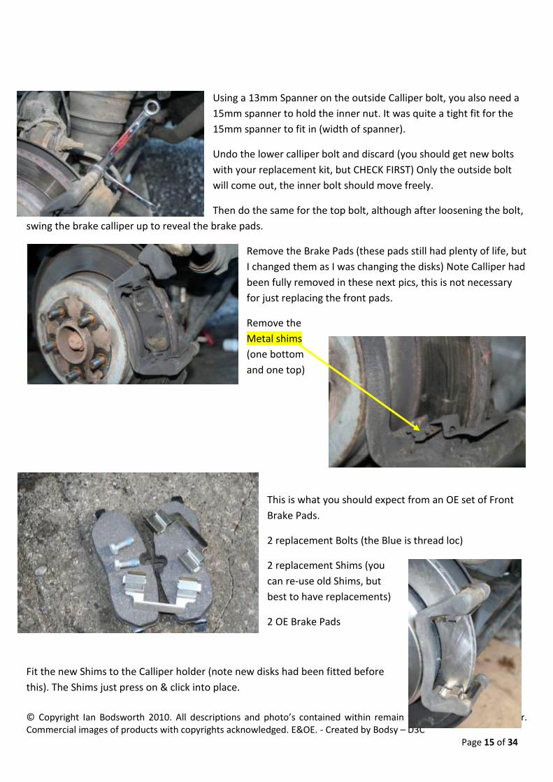
Using a 13mm Spanner on the outside Calliper bolt, you also need a
15mm spanner to hold the inner nut. It was quite a tight fit for the
15mm spanner to fit in (width of spanner).
Undo the lower calliper bolt and discard (you should get new bolts
with your replacement kit, but CHECK FIRST) Only the outside bolt
will come out, the inner bolt should move freely.
Then do the same for the top bolt, although after loosening the bolt,
swing the brake calliper up to reveal the brake pads.
Remove the Brake Pads (these pads still had plenty of life, but
I changed them as I was changing the disks) Note Calliper had
been fully removed in these next pics, this is not necessary
for just replacing the front pads.
Remove the
Metal shims
(one bottom
and one top)
This is what you should expect from an OE set of Front
Brake Pads.
2 replacement Bolts (the Blue is thread loc)
2 replacement Shims (you
can re-use old Shims, but
best to have replacements)
2 OE Brake Pads
Fit the new Shims to the Calliper holder (note new disks had been fitted before
this). The Shims just press on & click into place.

© Copyright Ian Bodsworth 2010. All descriptions and photo’s contained within remain the property of the Author. Commercial images of products with copyrights acknowledged. E&OE. - Created by Bodsy – D3C Page 16 of 34
Before fitting the Brake Pads,
ensure you use a liberal coating
of Copper Grease to the top and
bottom lugs of the brake pad to
keep the brake pads easily
moving. Applied by tube in this
case.
Re-fit the brake pads with the friction surface facing inwards. Be sure
that there is no grease on the front of the brake pad.
Note the chamfered edge on
the pads showing at the
bottom to assist with bedding
in.
With the brake Calliper, spray
plenty of brake cleaner on the
calliper and then use a Calliper Piston Retraction tool or other home
made device to retract the brake callipers into the body. This should be
done as squarely as possible. (NB. It may require you to remove some
of the Brake Fluid from the Master Cylinder, but I didn’t need to when
I did all four wheels).
Re-Fit the Brake Calliper into position and
re-fit the bottom calliper bolt that came
with the Brake pad kit using the 13mm
and 15mm spanner. Then remove the top
calliper bolt (discard it) and replace with
the other bolt from the Brake pad kit.
Tighten the bolts to 35Nm using the
torque wrench and 13mm socket.

© Copyright Ian Bodsworth 2010. All descriptions and photo’s contained within remain the property of the Author. Commercial images of products with copyrights acknowledged. E&OE. - Created by Bodsy – D3C Page 17 of 34
With the Brakes all attached, ensure that the Brake Pad Wear Sensor (drivers side rear) has the metal clip on it
before pushing gently back into position.
Rear Passenger side Rear Drivers Side

© Copyright Ian Bodsworth 2010. All descriptions and photo’s contained within remain the property of the Author. Commercial images of products with copyrights acknowledged. E&OE. - Created by Bodsy – D3C Page 18 of 34
6. How to change the Brake Pad Sensors – Front and Rear
There are 2 sensors, one on front nearside (passenger side) and one rear offside (drivers side). Front Sensor (See page 5 for tool matrix) Follow the first section of the 4. Changing Brake Pads Front. Up to the point where you have removed the Brake Pad Wear sensor at the Pad end. Check that it has worn through the plastic and that you definitely need to replace it.
If you look at the new one in the bag it'll give a good hint as to what you're looking for. As you remove the old sensor cable, replace it with the new one. This will help to ensure that you follow the correct route. Ensure you clip the cable into the same places as the old one. Once you get up near the top of the wheel arch you'll see the cable goes behind the plastic interior trim of the arch. It’s much easier if you undo or pull out the three nearest
plastic clips(removed) that hold the plastic arch in place. The arch is very strong, so don’t be afraid to bend it over & out of your way as much as possible. A piece of wood was used in this case to keep the plastic out of the way.
Now LOOK CAREFULLY at the connector on the new one, you'll see at the far end the clip mechanism that you need to release to get the old one off, DONT just pull, you'll break things.. Once it's off then plug in the new one. Well done, now you can put it all back together, if you didn’t snap any of the screw thingy’s then put them all back
Wheel back on and we're ready for the rear sensor.

© Copyright Ian Bodsworth 2010. All descriptions and photo’s contained within remain the property of the Author. Commercial images of products with copyrights acknowledged. E&OE. - Created by Bodsy – D3C Page 19 of 34
Rear Sensor Follow the first section of the 5. Changing Brake Pads Rear. Up to the point where you have removed the Brake Pad Wear sensor at the Pad end. Check that it has worn through the plastic end and that you definitely need to replace it. If you look at the new one in the bag it'll give a good hint as to what you're looking for. As you remove the old sensor cable, replace it with the new one. This will help to ensure that you follow the correct route. Ensure you clip the cable into the same places as the old one.
The difference with the rear sensor, is that the cable DOESNT go up inside the car, it follows round the back of the suspension drum and clips in just behind, you can reach it from the left side of the drum. By the end you should have maybe a couple of bloody knuckles as well as a nice scratch up your right arm…
Thanks to Ade & Richard for supplying the sensor pics & Ade for the initial write up. N.B. If you DON’T want to have brake pad wear sensors enabled, then simply cut the old sensor at an appropriate point between the end of the sensor and the connector and join the two resulting wires together. Seal with waterproof tape or sealant and tuck up out of the way. It will think that the circuit is completed and therefore that the brakes are OK. If you take this option, you must ensure that you regularly check your brake pads and disks and take any
necessary remedial action as the car will no longer warn you of imminent wear.

© Copyright Ian Bodsworth 2010. All descriptions and photo’s contained within remain the property of the Author. Commercial images of products with copyrights acknowledged. E&OE. - Created by Bodsy – D3C Page 20 of 34
7. How to change the Brake Disks – Front
Follow the instructions in section 4 to remove the brake pads.
Tools Required to Change Front Brake Disks (See page 5 for tool matrix)
Pliers
Brake Cleaner
Spanners, 13mm, 17mm
Rubber Mallet
Copper Grease
Optional Ratchet
21mm Bi-Hex socket
Socket 13mm
Torque Wrench
Strong Wire or String
T50 Torx Bit
Breaker Bar
Discard the brake pads and ensure you fit new brake pads when
you fit new brake disks. See section 4. How to change the Brake
Pads - Front
Fully remove the calliper and ensure that it is supported so that
you do not put too much strain on the brake pipe components. I
used a piece of strong wire and tied it to form a loop. As per
picture.
Then find the Torx Screw
(Size T50) on the face of
the disk.
Clear out any brake dust or mud from the screw head. Brake Disk
cleaner is ideal.
Insert the Torx and gently tap it in with a hammer to ensure it is
fully home.
Then undo the Screw carefully. I generally tend to very
slightly tighten the screw to break any seal that has
formed and then undo the screw. The hub may still move,

© Copyright Ian Bodsworth 2010. All descriptions and photo’s contained within remain the property of the Author. Commercial images of products with copyrights acknowledged. E&OE. - Created by Bodsy – D3C Page 21 of 34
so I start with a few sharp taps on the end of the ratchet to get the screw moving.
You then need to remove the calliper bracket.
There are two 21mm Bi-Hex bolts. These will be very stiff and
require a breaker bar to undo.
For the top bolt, you
could also remove the
cable bracket if you need
to gain better access,
just be careful with the
wheel speed sensor
cable.
Bottom Bolt should be clear.
With the Bracket
removed, KEEP THE
BOLTS, these do not get
replaced in a disk kit.
The T50 screw can be removed, along with the brake disk. The
disk MAY need to be gently tapped off with a rubber mallet or
similar.

© Copyright Ian Bodsworth 2010. All descriptions and photo’s contained within remain the property of the Author. Commercial images of products with copyrights acknowledged. E&OE. - Created by Bodsy – D3C Page 22 of 34
You can see the new and old Disk side by side. The old disk has a very prominent ‘lip’ on the inside
of the disks. This can sometimes be removed as long as the width of the disk is still within
tolerance (27mm minimum for Front).
Put the new disk on, remembering to align the Torx
Screw hole onto the hub. When re-fitting the screw, I
put some medium thread lock on to keep it in place.
Using the Torque Wrench, set it for 35Nm and tighten
the Torx screw.
Tap the Disk on fully and check the torque setting again.
You then need to re-fit the Calliper carrier bracket. Again, I
applied some medium thread loc before re-fitting.
Set the Torque Wrench to 275Nm. Note that this is very high and
most ‘normal’ torque wrenches will only go up to 200Nm.
When both bolts have been re-fitted and the
torque set, continue to refit the brake pads and
calliper. See section 4. How to change the Brake
Pads - Front

© Copyright Ian Bodsworth 2010. All descriptions and photo’s contained within remain the property of the Author. Commercial images of products with copyrights acknowledged. E&OE. - Created by Bodsy – D3C Page 23 of 34
8. How to change the Brake Disks – Rear
Follow the instructions in section 5 to remove the brake pads.
Tools Required to Change Rear Brake Disks (See page 5 for tool matrix)
Pliers
Brake Cleaner
Spanners, 13mm, 15mm
Rubber Mallet
Flat Blade Screwdriver
Copper Grease
Optional Ratchet
15mm Bi-Hex socket
Socket 13mm
Torque Wrench
Strong Wire or String
T50 Torx Bit
Breaker Bar
32mm Socket (1-1/4”)
Torch
Before removing the rear Brake disks, please carry out this sequence to put the Electronic Park
Brake into Service Mode. Ensure brake pads and calliper is fitted to all wheels.
In the car, press the brake pedal three times and hold the pedal down. Push down on the EPB
switch for 3-5 seconds.
Go to the main fuse box in the engine bay and remove FL8 fuse 30A (pink Fuse) this will ensure
that the EPB is not accidentally re-engaged.
Following the first section on how to change the brake pads, lift and remove the road wheels.
Discard the brake pads and ensure you fit new brake pads when you fit new brake disks. See How
to change the Brake Pads - Rear
Fully remove the calliper and ensure that it is
supported so that you do not put too much
strain on the
brake pipe
components. I
used a piece of
strong wire and
tied it to form a
loop. As per
picture.
You then need to remove the calliper bracket.
There are two 15mm Bi-Hex bolts. These will be very stiff and
require a breaker bar to undo.

© Copyright Ian Bodsworth 2010. All descriptions and photo’s contained within remain the property of the Author. Commercial images of products with copyrights acknowledged. E&OE. - Created by Bodsy – D3C Page 24 of 34
With the Bracket removed, KEEP THE BOLTS, these do not get replaced in a disk kit.
Using a flat blade screwdriver, remove the plastic
plug to reveal a hole.
Then find the Torx Screw (Size T50) on the face of the
disk.
Clear out any brake dust or mud from the screw head. Brake Dust
cleaner is ideal.
Insert the Torx and gently tap it in with a hammer to ensure it is
fully home.
Then undo the Screw carefully. I generally tend to very slightly
tighten the screw to break any seal that has formed and then undo the
screw. The hub may still move, so I start with a few sharp taps on the
end of the ratchet to get the screw
moving.
Turn the disk until the hole (that you
removed the plastic plug from) is at the
bottom (Drivers side is upside down
from Passenger side). (you could use a
torch to help) Behind the disk, it looks
like this:-

© Copyright Ian Bodsworth 2010. All descriptions and photo’s contained within remain the property of the Author. Commercial images of products with copyrights acknowledged. E&OE. - Created by Bodsy – D3C Page 25 of 34
Using the flat blade screwdriver through the hole, release the ratchet one click at a time until it is
fully undone.
Then the T50 screw can be removed, along with the brake disk. The disk MAY need to be gently
tapped off with a rubber mallet or similar.
You can see the new and old Disk side by side. The
old disk has a very prominent ‘lip’ on the inside of
the disks. This can sometimes be removed as long as
the width of the disk is still within tolerance(Rear
disk is
17mm
minimum)
You will
more than likely need to give the disk a quick clean with
brake cleaner to remove any oils that may be on the
braking faces of the disk.
Put the new disk on, remembering to align the Torx
Screw hole onto the hub. When re-fitting the screw, I put
some medium thread lock on to keep it in place.
© Copyright Ian Bodsworth 2010. All descriptions and photo’s contained within remain the property of the Author. Commercial images of products with copyrights acknowledged. E&OE. - Created by Bodsy – D3C Page 26 of 34
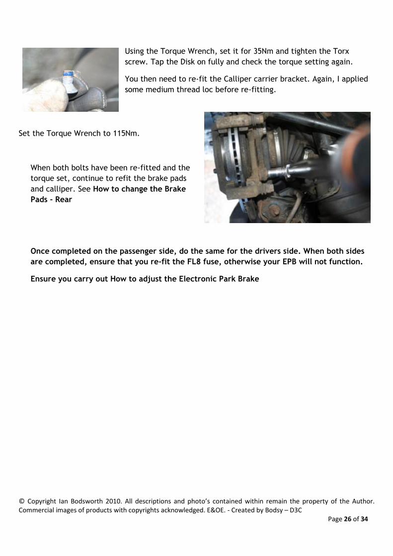
Using the Torque Wrench, set it for 35Nm and tighten the Torx
screw. Tap the Disk on fully and check the torque setting again.
You then need to re-fit the Calliper carrier bracket. Again, I applied
some medium thread loc before re-fitting.
Set the Torque Wrench to 115Nm.
When both bolts have been re-fitted and the
torque set, continue to refit the brake pads
and calliper. See How to change the Brake
Pads - Rear
Once completed on the passenger side, do the same for the drivers side. When both sides
are completed, ensure that you re-fit the FL8 fuse, otherwise your EPB will not function.
Ensure you carry out How to adjust the Electronic Park Brake

© Copyright Ian Bodsworth 2010. All descriptions and photo’s contained within remain the property of the Author. Commercial images of products with copyrights acknowledged. E&OE. - Created by Bodsy – D3C Page 27 of 34
9. How to adjust the Electronic Park Brake
The Electronic Park Brake is operated by a pair of brake shoes on the inside of the rear brake disks.
The manufacturer recommends that you strip, clean and adjust the EPB after 50 miles of off road conditions
or arduous use.
If you have a loud screeching noise when the EPB is applied, then often an adjustment of the Electronic Park
Brake will fix this.
This procedure MUST be carried out when you change your brake disks and/or brake shoes. If the pads are worn below
the limit, you should replace the pads as well as go through the Electronic Parking Brake Shoe Bedding In Procedure.
Tools Required to adjust the Electronic Park Brake(See page 5 for tool matrix)
Flat Blade Screwdriver
32mm Socket (1-1/4”)
Torque Wrench
Allen Key/Hex (4mm)
Ensure that your rear wheels are off the ground and the car is on axle stands or a car lift. Remove
the rear road wheels.
For a Manual, you don't want the EPB to apply automatically, you should Push the EPB button
DOWN whilst switching off the ignition and removing the key.
For an Auto, just don't apply it.
The above should be fine if you are leaving the disks on and just adjusting the EPB.
If you're removing the disks for a full clean, then I'd recommend putting it into service mode and
removing the 30a fuse as per section 7 How to Change Your Brake Disks – Rear of the bible.
There are two adjustment parts to the EPB.
Using a flat blade screwdriver, remove the plastic lug
to reveal a hole. Turn the disk using the 32mm Hub
Socket until the hole (that you removed the plastic
plug from) is aligned with the first adjustment point.

© Copyright Ian Bodsworth 2010. All descriptions and photo’s contained within remain the property of the Author. Commercial images of products with copyrights acknowledged. E&OE. - Created by Bodsy – D3C Page 28 of 34
Behind the disk, it looks like this (passenger side. Drivers side will be upside down to this) :-
There are two adjustment points. One is
the 4mm Hex bolt(Allen Key) (circled
Yellow). The other is the ratchet (hidden at
the bottom, circled in Red)
Rotate the disk again until the hole is in
line with the ratchet adjuster (Red) (The
direction of rotation must always be
forward). Using the flat blade screwdriver
through the hole, tighten the ratchet until
it is tight.
Then take your torque wrench and 32mm
socket and set it for between 40 and 90Nm.
Place it on the hub nut and if the disk
turns, you need to add one click at a time to the ratchet with the screwdriver until the required
torque is reached (I set my torque to 60Nm for this exercise). When the Torque is reached, then
you need to release the ratchet by exactly 8 clicks back.
Finally, rotate the disk until the hole is in line with the Hex socket (Yellow) and undo this half a
turn. Gently tap the disk with a rubber faced mallet around the shoe area. This will release the
tension and it should naturally move if it needs to. Tighten the Hex socket back up to 6Nm.
When that is completed (on both rear wheels), replace the plastic lug and re-fit the road wheels.
If they are new disks or pads, please complete Section 10 How to Bed In New EPB Shoes.
© Copyright Ian Bodsworth 2010. All descriptions and photo’s contained within remain the property of the Author. Commercial images of products with copyrights acknowledged. E&OE. - Created by Bodsy – D3C Page 29 of 34
10. How to fit new EPB Shoes
(See page 5 for Tool Matrix) Remove the brake Disks (see 8. How to Change the Brake Disks – Rear).
You should replace your EPB Shoes when the lining material is down to 2mm.
Images shown here are for the Drivers side rear.
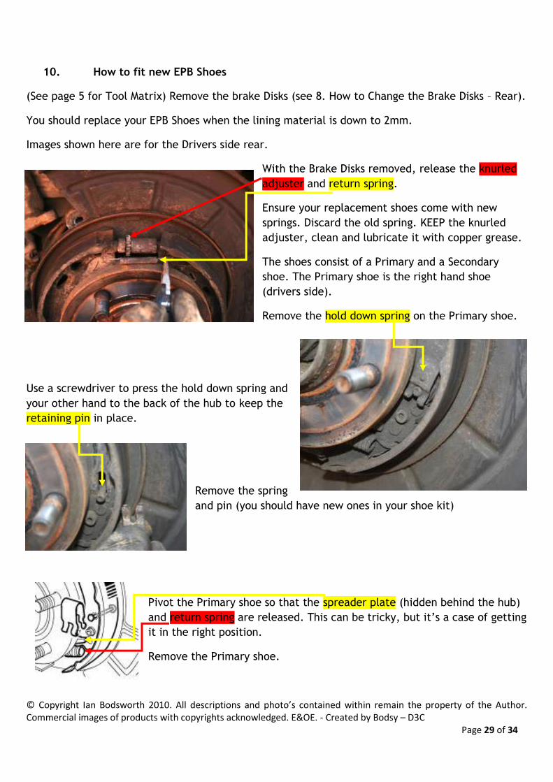
With the Brake Disks removed, release the knurled
adjuster and return spring.
Ensure your replacement shoes come with new
springs. Discard the old spring. KEEP the knurled
adjuster, clean and lubricate it with copper grease.
The shoes consist of a Primary and a Secondary
shoe. The Primary shoe is the right hand shoe
(drivers side).
Remove the hold down spring on the Primary shoe.
Use a screwdriver to press the hold down spring and
your other hand to the back of the hub to keep the
retaining pin in place.
Remove the spring
and pin (you should have new ones in your shoe kit)
Pivot the Primary shoe so that the spreader plate (hidden behind the hub)
and return spring are released. This can be tricky, but it’s a case of getting
it in the right position.
Remove the Primary shoe.
© Copyright Ian Bodsworth 2010. All descriptions and photo’s contained within remain the property of the Author. Commercial images of products with copyrights acknowledged. E&OE. - Created by Bodsy – D3C Page 30 of 34
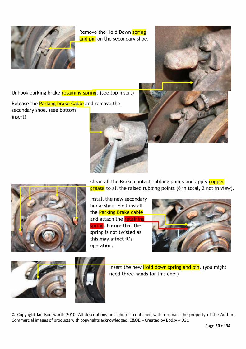
Remove the Hold Down spring
and pin on the secondary shoe.
Unhook parking brake retaining spring. (see top insert)
Release the Parking brake Cable and remove the
secondary shoe. (see bottom
insert)
Clean all the Brake contact rubbing points and apply copper
grease to all the raised rubbing points (6 in total, 2 not in view).
Install the new secondary
brake shoe. First install
the Parking Brake cable
and attach the retaining
spring. Ensure that the
spring is not twisted as
this may affect it’s
operation.
Insert the new Hold down spring and pin. (you might
need three hands for this one!)

© Copyright Ian Bodsworth 2010. All descriptions and photo’s contained within remain the property of the Author. Commercial images of products with copyrights acknowledged. E&OE. - Created by Bodsy – D3C Page 31 of 34
Insert the new Return Spring. Please note the direction
of the ‘hook’ If you install it upside down, you will not
be able to connect it to the Primary shoe.
Install the Spreader Plate and Spring. See pic for
installed components off the car (as an example).
Use a small tie wrap on the spreader plate spring to
make it easier to install (Make sure you remember to cut
it off once the plate is installed).
Insert the knurled adjuster (I put some
copper grease on to ensure it doesn’t
seize)
Also insert and
attach the return
spring
Insert the replacement hold down
spring and pin.
Once you have completed that, you need to re-fit the Brake
Disk. You may find that the disk does not fit on easily, you
may need to gently tap the shoes to move them up or down
on the hub so that the disk fits over them. I found that rotating the disk helped it to fit back on.
With the Disk on, you need to complete the brake calliper and pads installation and then go on to
section 8. How To adjust the Electronic Parking Brake.

© Copyright Ian Bodsworth 2010. All descriptions and photo’s contained within remain the property of the Author. Commercial images of products with copyrights acknowledged. E&OE. - Created by Bodsy – D3C Page 32 of 34
11. How to Bed in new EPB shoes
You need to bed in the EPB shoes either when you have changed the EPB shoes or you have
changed the rear discs.
With the Engine running, press the brake pedal fully on and off 3 times. On the third press, hold
the brake pedal down.
With the brake pedal still in the down position, pull the EPB switch upwards 4 times and then
downwards 3 times. This must be completed within 10 seconds.
Your dash display will then show ‘Park Brake Bedding Cycle Active’ or something similar. If it
hasn’t, then release the brake pedal and try again.
You need to ensure that you are on a clear piece of road or land as this procedure needs to be
completed 10 times.
Drive at least 19mph and maximum of 29mph and then apply the EPB switch until you stop. You
then need to wait for 60 seconds or drive for 500metres (to allow the brakes to cool down) before
repeating the process. If you stop the engine or you drive over 30 MPH, the bedding in process will
be cancelled. At the end of the 10th time, the bedding in mode may automatically finish, or you
should just drive more than 30mph or cycle the ignition.

© Copyright Ian Bodsworth 2010. All descriptions and photo’s contained within remain the property of the Author. Commercial images of products with copyrights acknowledged. E&OE. - Created by Bodsy – D3C Page 33 of 34
12. How to replace the brake fluid and Bleed the braking system
Write up and Photo’s in due course. If anyone would like to provide me with their detailed write
up and photo’s if they do this before I do, then please feel free to send to me so I can update
Bodsy’s Brake Bible!

© Copyright Ian Bodsworth 2010. All descriptions and photo’s contained within remain the property of the Author. Commercial images of products with copyrights acknowledged. E&OE. - Created by Bodsy – D3C Page 34 of 34
Where to buy from…..
LandRover directly, I’ve found Yeovil Landrover to be very accommodating for Genuine LR
Parts. Mention Bodsy’s Brake Bible and you may get extra discount.
Speak to Nick the Parts Manager – 01935 476660
For Non OEM parts, then I’ve found 4-Tech Land Rover specialists to also be very
accommodating. Likewise, mention Bodsy’s Brake Bible and you may get extra discount.
Speak to Gordon 01945 871335
For Tools, all of the tools used in this guide are widely available from your local tool
supplier. Such as Halfords or your local autoparts store.