Embed Size (px)
Citation preview
Bob Brehm, AK6R
Chief Engineer Palomar-Engineers.com
Copyright 2014 Palomar Engineers, Inc.
RFI Workshop Objectives Learn fundamentals of RFI
How ferrites work to suppress RFI
How to use ferrite kits to solve specific RFI problems in your shack
RF feed lines
AC/DC power lines
How to solve neighborhood RFI problems
What is RFI? Radio Frequency Interference/Electromagnetic
Interference (RFI/EMI) – at radio frequencies
A radio frequency disturbance that causes an unwanted interruption, degradation, or obstruction to an electrical circuit.
Common Sources
Radio Transmitters (Amateur, broadcast, consumer devices)
Natural: Sun, Cosmic noise, Lightning, atmospheric static
Electro-mechanical devices (motors), ignition systems
All sources cause rapidly changing electrical currents in the effected device which cause unintended operation(VICTIM)
Got RFI in your shack/home? Symptoms – caused by your transmitter or antenna
Hot microphone – lip burns, distorted audio
Resonant antennas don’t tune correctly or high SWR
Your voice/transmission causes interference with computer, TV, Stereo/Home Theater system, security system, garage door opener, microwave, telephone, DSL/cable modems/router, fax machine, touch on/off lamps, flickering lights, LED string lights, smoke/CO2 alarm, answering machine, sprinkler system
Degradation of computer data throughput or loss of data , computer/internet stops working
Got RFI Noise in your shack? Symptoms – receiver noise caused by outside sources
Clicks, buzzes, birdies, or chirps in your receiver on 1 or more bands
High noise level – periodic or varies by time of day
Receiver overload or desensing of front end with no signal present
Motor “noise” of varying/constant pitch – often caused by fans, heater/blower motors, heat pumps, fuel pumps
Florescent light crackle or buzzing or arcing sound
Switching power supplies, battery chargers, inverters, solar controllers, plasma TV, digital gear “GRUNGE"
Got Neighborhood RFI?
IT’S ALL YOUR FAULT WITH THAT BIG ANTENNA!
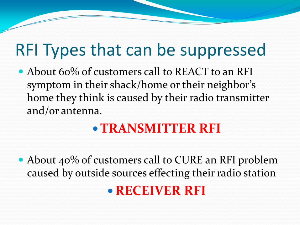
RFI Types that can be suppressed About 60% of customers call to REACT to an RFI
symptom in their shack/home or their neighbor’s home they think is caused by their radio transmitter and/or antenna.
TRANSMITTER RFI
About 40% of customers call to CURE an RFI problem caused by outside sources effecting their radio station
RECEIVER RFI
Causes and Cures to make ham radio more enjoyable
How is RFI
Transferred?
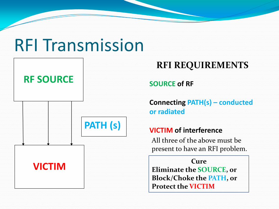
RFI Transmission RFI REQUIREMENTS
SOURCE of RF Connecting PATH(s) – conducted or radiated VICTIM of interference
All three of the above must be present to have an RFI problem.
RF SOURCE
VICTIM
PATH (s)
Cure Eliminate the SOURCE, or Block/Choke the PATH, or Protect the VICTIM
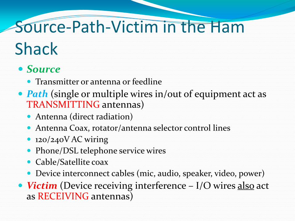
Source-Path-Victim in the Ham Shack Source Transmitter or antenna or feedline
Path (single or multiple wires in/out of equipment act as TRANSMITTING antennas) Antenna (direct radiation)
Antenna Coax, rotator/antenna selector control lines
120/240V AC wiring
Phone/DSL telephone service wires
Cable/Satellite coax
Device interconnect cables (mic, audio, speaker, video, power)
Victim (Device receiving interference – I/O wires also act as RECEIVING antennas)
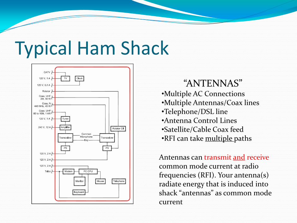
Typical Ham Shack
“ANTENNAS” •Multiple AC Connections •Multiple Antennas/Coax lines •Telephone/DSL line •Antenna Control Lines •Satellite/Cable Coax feed •RFI can take multiple paths
Antennas can transmit and receive common mode current at radio frequencies (RFI). Your antenna(s) radiate energy that is induced into shack “antennas” as common mode current
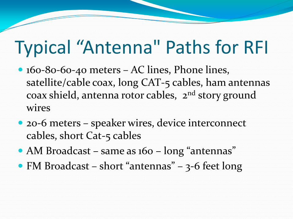
Typical “Antenna" Paths for RFI 160-80-60-40 meters – AC lines, Phone lines,
satellite/cable coax, long CAT-5 cables, ham antennas coax shield, antenna rotor cables, 2nd story ground wires
20-6 meters – speaker wires, device interconnect cables, short Cat-5 cables
AM Broadcast – same as 160 – long “antennas”
FM Broadcast – short “antennas” – 3-6 feet long
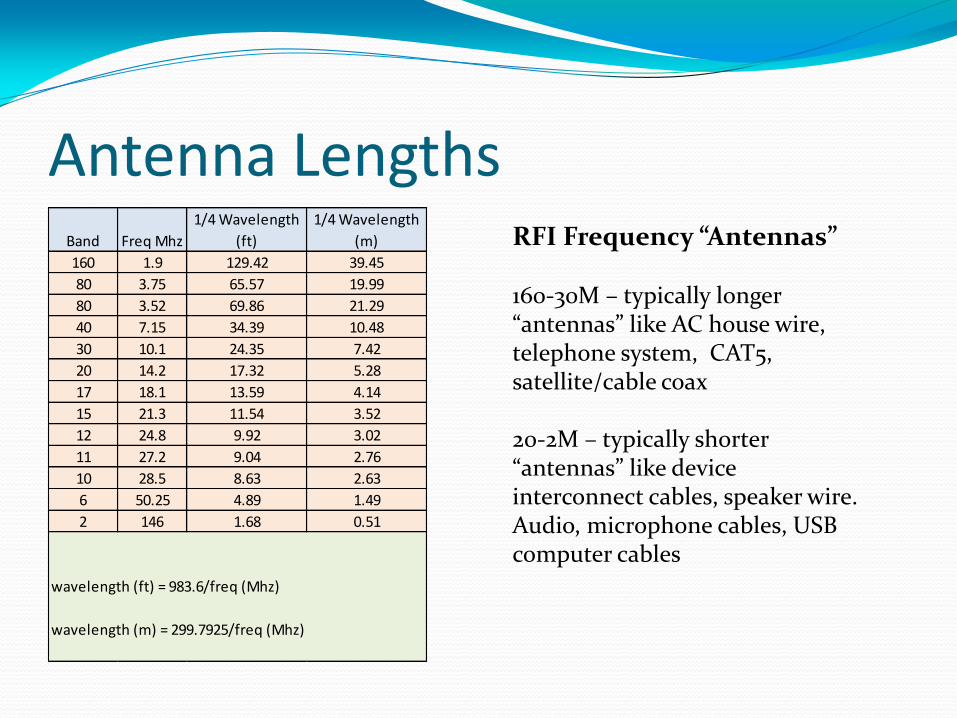
Antenna Lengths RFI Frequency “Antennas” 160-30M – typically longer “antennas” like AC house wire, telephone system, CAT5, satellite/cable coax 20-2M – typically shorter “antennas” like device interconnect cables, speaker wire. Audio, microphone cables, USB computer cables
Band Freq Mhz
1/4 Wavelength
(ft)
1/4 Wavelength
(m)
160 1.9 129.42 39.45
80 3.75 65.57 19.99
80 3.52 69.86 21.29
40 7.15 34.39 10.48
30 10.1 24.35 7.42
20 14.2 17.32 5.28
17 18.1 13.59 4.14
15 21.3 11.54 3.52
12 24.8 9.92 3.02
11 27.2 9.04 2.76
10 28.5 8.63 2.63
6 50.25 4.89 1.49
2 146 1.68 0.51
wavelength (ft) = 983.6/freq (Mhz)
wavelength (m) = 299.7925/freq (Mhz)
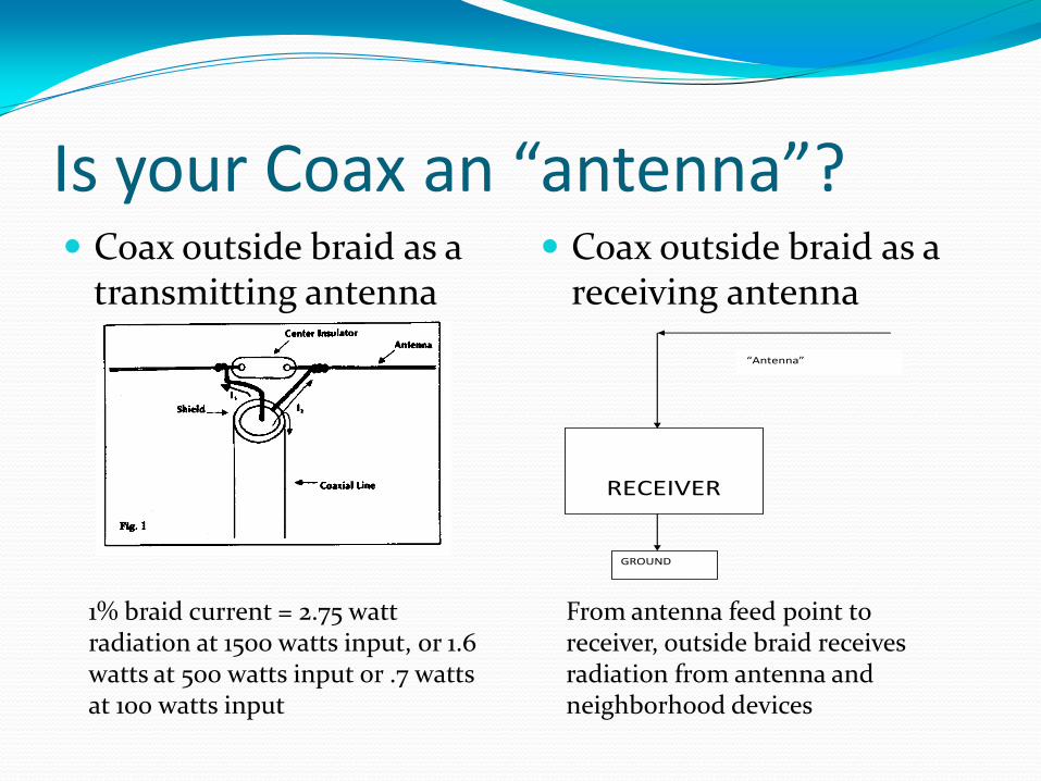
Is your Coax an “antenna”? Coax outside braid as a
transmitting antenna Coax outside braid as a
receiving antenna
RECEIVER
GROUND
“Antenna”
From antenna feed point to receiver, outside braid receives radiation from antenna and neighborhood devices
1% braid current = 2.75 watt radiation at 1500 watts input, or 1.6 watts at 500 watts input or .7 watts at 100 watts input
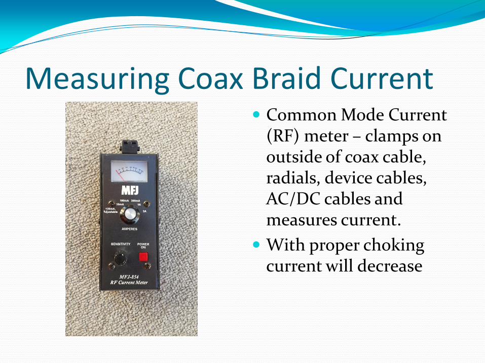
Measuring Coax Braid Current Common Mode Current
(RF) meter – clamps on outside of coax cable, radials, device cables, AC/DC cables and measures current.
With proper choking current will decrease
Reduce RFI current to reduce RFI I = E/R
Where I = Common Mode Current - IRFI
E = voltage on coax
R = Choking impedance (Z=R+j) to reduce I
Higher Z means less I = less RFI because
IRFI = E/Z
An “antenna” is a wire with alternating current going through it creating an electromagnetic field of radiation.
Reducing the current through the wire, reduces the radiation.
Without choking, the outside coax braid is an unwanted antenna
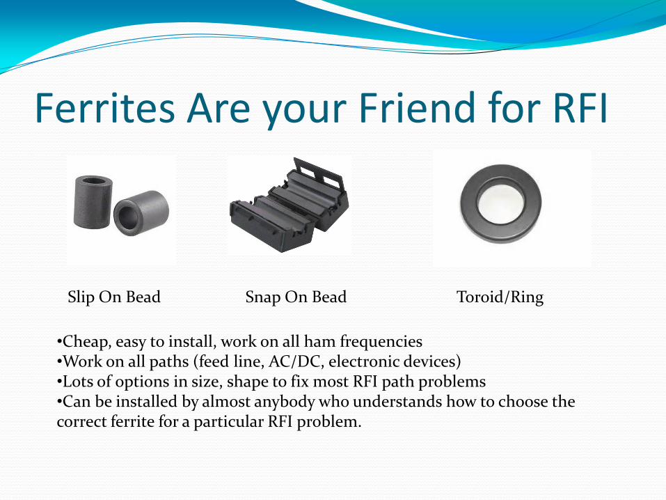
Ferrites Are your Friend for RFI
Slip On Bead Snap On Bead Toroid/Ring
•Cheap, easy to install, work on all ham frequencies •Work on all paths (feed line, AC/DC, electronic devices) •Lots of options in size, shape to fix most RFI path problems •Can be installed by almost anybody who understands how to choose the correct ferrite for a particular RFI problem.
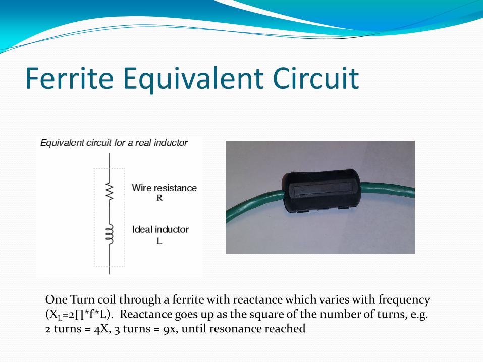
Ferrite Equivalent Circuit
One Turn coil through a ferrite with reactance which varies with frequency (XL=2∏*f*L). Reactance goes up as the square of the number of turns, e.g. 2 turns = 4X, 3 turns = 9x, until resonance reached
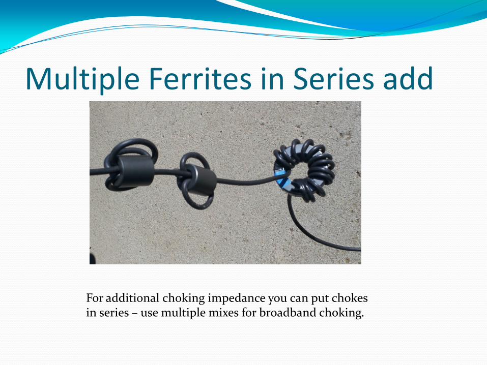
Multiple Ferrites in Series add
For additional choking impedance you can put chokes in series – use multiple mixes for broadband choking.
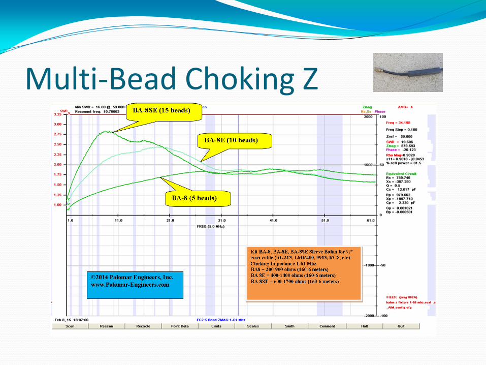
Multi-Bead Choking Z
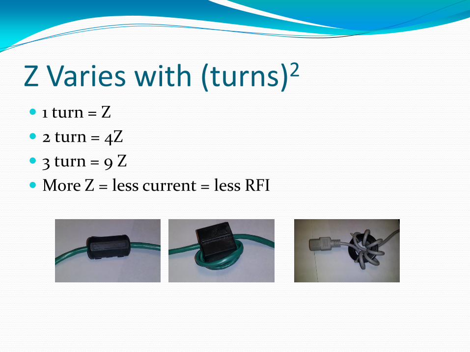
Z Varies with (turns)2
1 turn = Z
2 turn = 4Z
3 turn = 9 Z
More Z = less current = less RFI
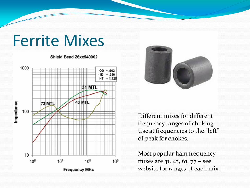
Ferrite Mixes
Different mixes for different frequency ranges of choking. Use at frequencies to the “left” of peak for chokes. Most popular ham frequency mixes are 31, 43, 61, 77 – see website for ranges of each mix.
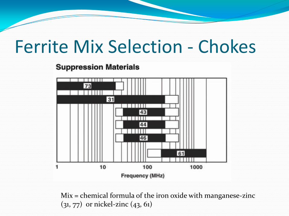
Ferrite Mix Selection - Chokes
Mix = chemical formula of the iron oxide with manganese-zinc (31, 77) or nickel-zinc (43, 61)
Ferrite Use Recap Determine frequency range of RFI
Choose proper mix (31, 61, 77) to suppress RFI
Choose Topology(slip, snap, ring) to fit the Path
Install ferrites – retest for RFI suppression
Consider additional Paths if RFI persists
How does this solution apply to your ham shack/home?
Suppress TRANSMITTER RFI, reduce RECEIVER RFI/NOISE
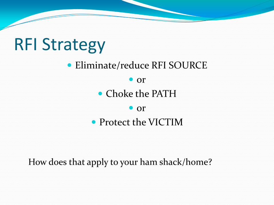
RFI Strategy Eliminate/reduce RFI SOURCE
or
Choke the PATH
or
Protect the VICTIM
How does that apply to your ham shack/home?
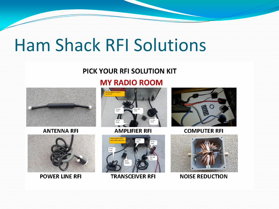
Ham Shack RFI Solutions
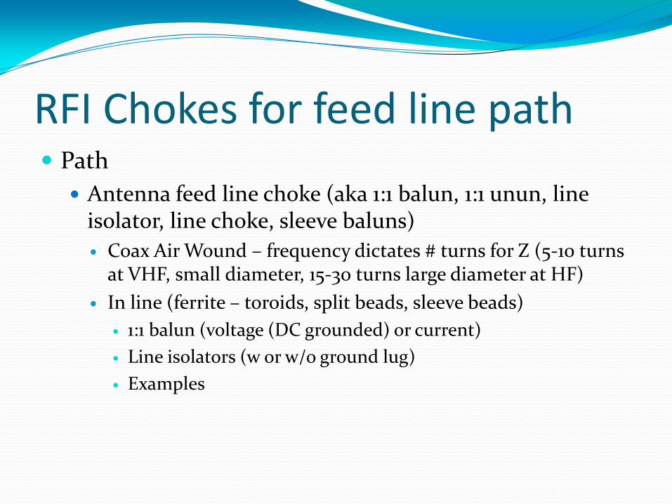
RFI Chokes for feed line path Path
Antenna feed line choke (aka 1:1 balun, 1:1 unun, line isolator, line choke, sleeve baluns)
Coax Air Wound – frequency dictates # turns for Z (5-10 turns at VHF, small diameter, 15-30 turns large diameter at HF)
In line (ferrite – toroids, split beads, sleeve beads)
1:1 balun (voltage (DC grounded) or current)
Line isolators (w or w/o ground lug)
Examples
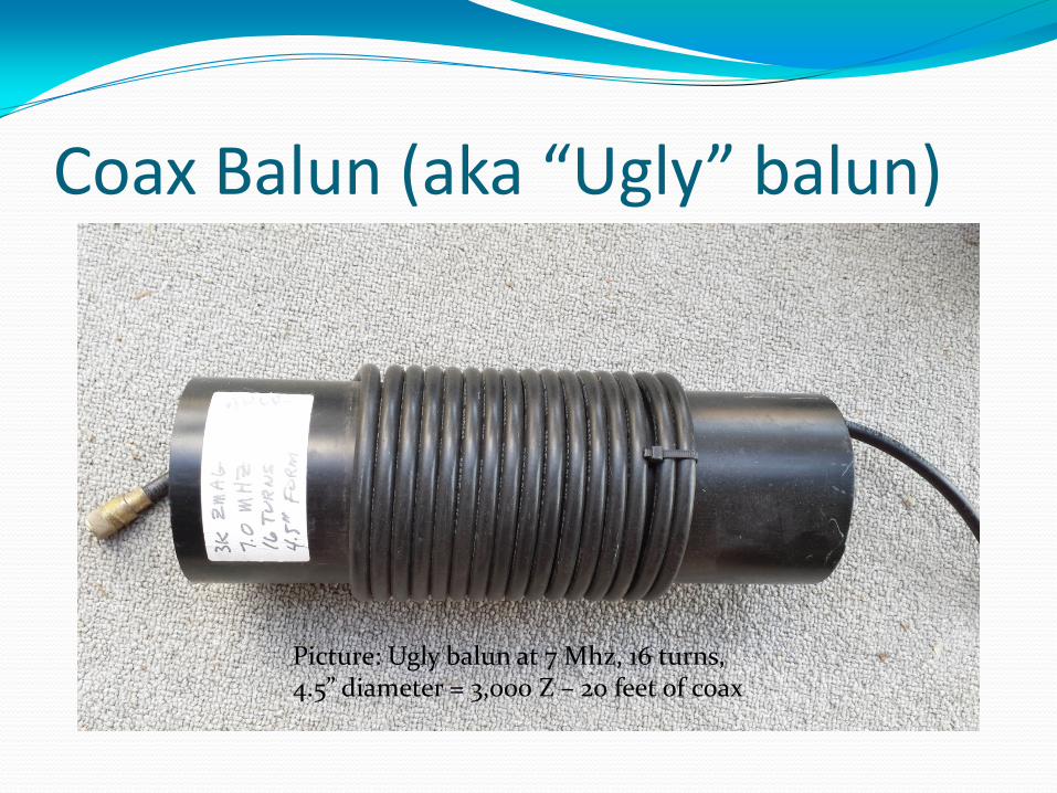
Coax Balun (aka “Ugly” balun)
Picture: Ugly balun at 7 Mhz, 16 turns, 4.5” diameter = 3,000 Z – 20 feet of coax
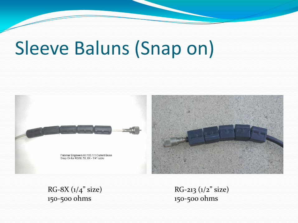
Sleeve Baluns (Snap on)
RG-8X (1/4” size) 150-500 ohms
RG-213 (1/2” size) 150-500 ohms

Large Clamp On (FSB-1) = 1” ID
3 turns = 1K ohms
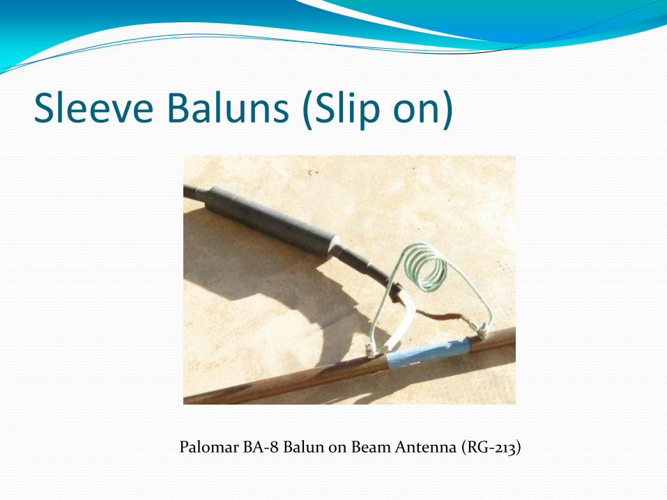
Sleeve Baluns (Slip on)
Palomar BA-8 Balun on Beam Antenna (RG-213)
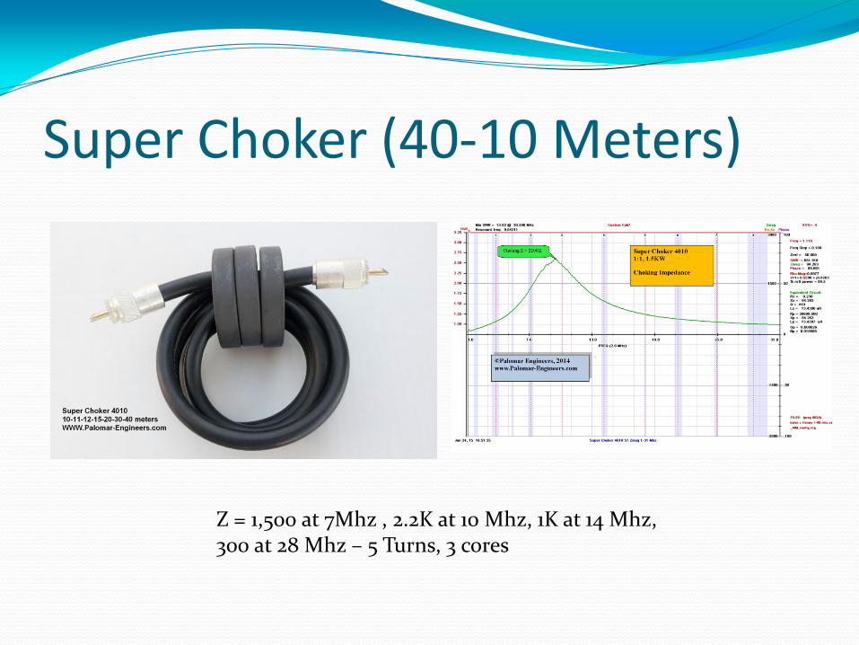
Super Choker (40-10 Meters)
Z = 1,500 at 7Mhz , 2.2K at 10 Mhz, 1K at 14 Mhz, 300 at 28 Mhz – 5 Turns, 3 cores
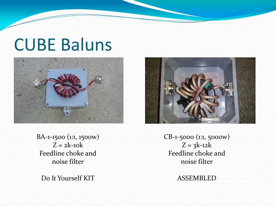
CUBE Baluns
BA-1-1500 (1:1, 1500w) Z = 2k-10k
Feedline choke and noise filter
Do It Yourself KIT
CB-1-5000 (1:1, 5000w) Z = 3k-12k
Feedline choke and noise filter
ASSEMBLED
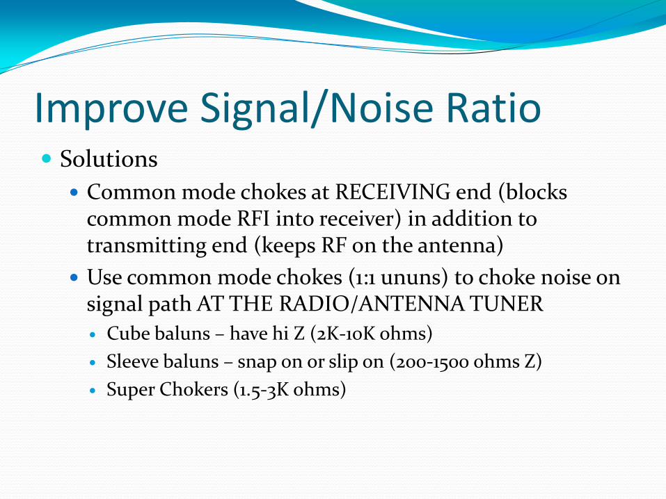
Improve Signal/Noise Ratio Solutions
Common mode chokes at RECEIVING end (blocks common mode RFI into receiver) in addition to transmitting end (keeps RF on the antenna)
Use common mode chokes (1:1 ununs) to choke noise on signal path AT THE RADIO/ANTENNA TUNER
Cube baluns – have hi Z (2K-10K ohms)
Sleeve baluns – snap on or slip on (200-1500 ohms Z)
Super Chokers (1.5-3K ohms)

Testimonial Case WOW...
I just tried one of your toroids on my modest antenna system. I have a Hamstick on top of an all aluminum manufactured home. Its the best ground plane one could hope for, and I've made contacts to Korea on 40m with it.
Before... on 40m I had an AM background noise of 5S units. I wrapped about 10 turns into one of the toroids right by the radio and the noise floor dropped to below 1 S unit ( not readable on my TS-480s).
You know... when I got this from you yesterday, I figured maybe 2 S units if that and the price was right... I am truly amazed by the results!!!
Bob K2IU (2/25/2014)
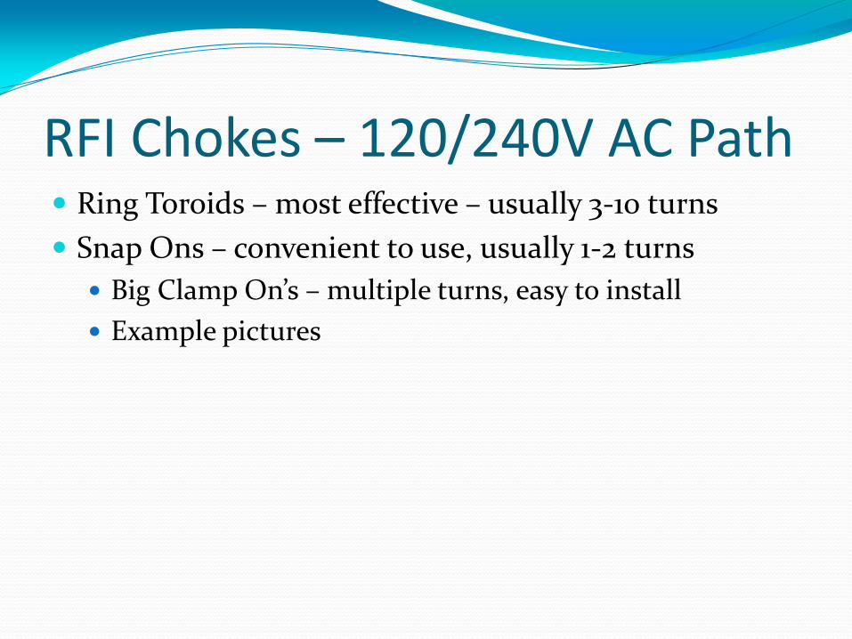
RFI Chokes – 120/240V AC Path Ring Toroids – most effective – usually 3-10 turns
Snap Ons – convenient to use, usually 1-2 turns
Big Clamp On’s – multiple turns, easy to install
Example pictures
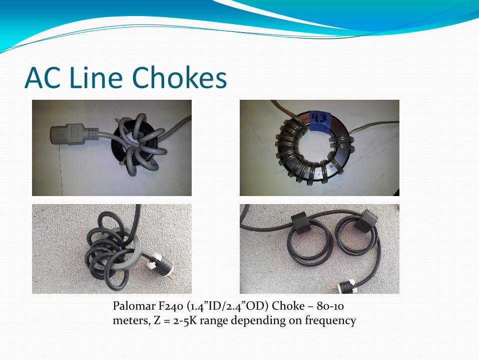
AC Line Chokes
Palomar F240 (1.4”ID/2.4”OD) Choke – 80-10 meters, Z = 2-5K range depending on frequency
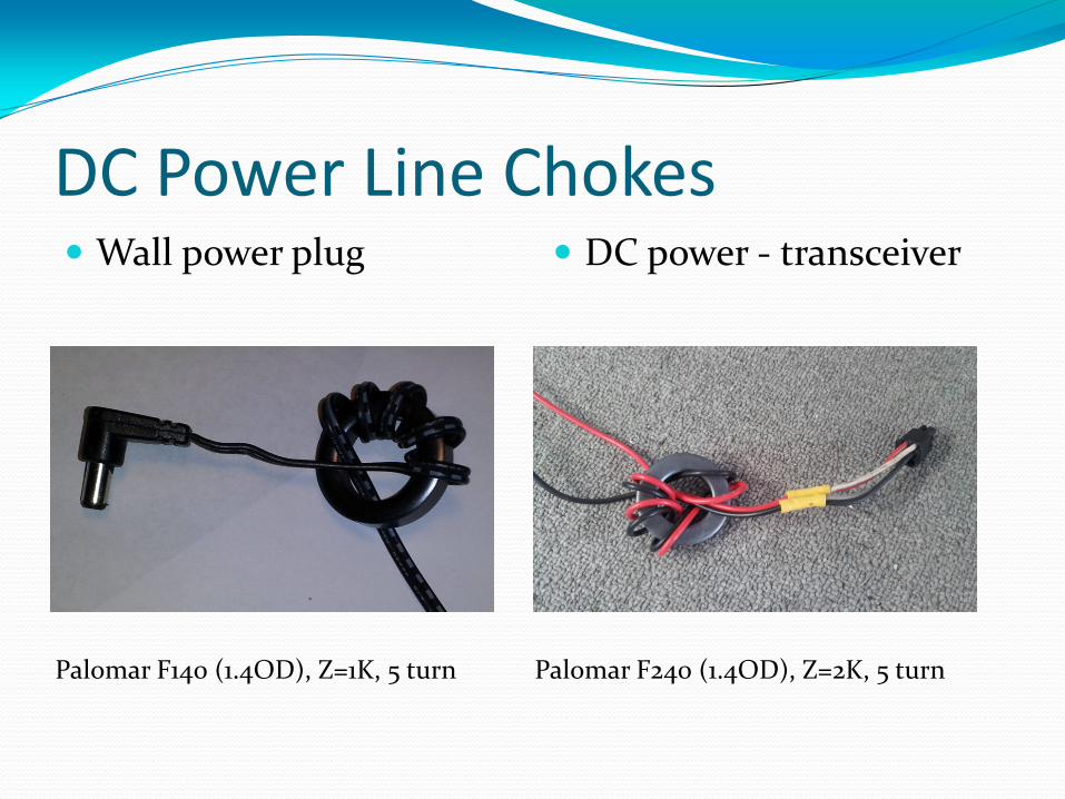
DC Power Line Chokes Wall power plug DC power - transceiver
Palomar F140 (1.4OD), Z=1K, 5 turn Palomar F240 (1.4OD), Z=2K, 5 turn
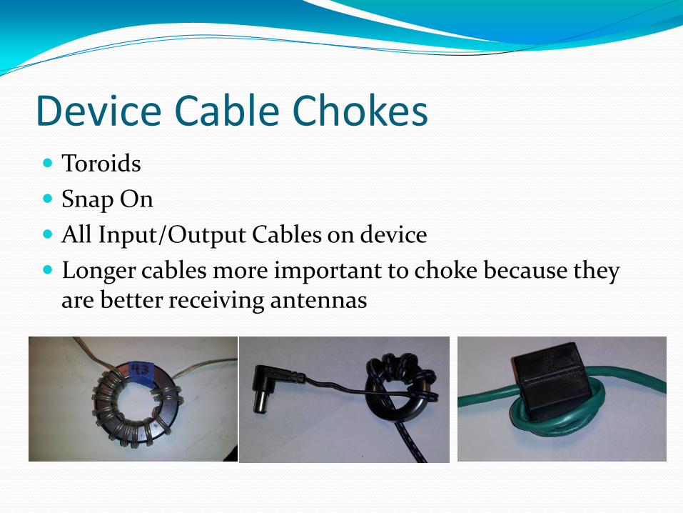
Device Cable Chokes Toroids
Snap On
All Input/Output Cables on device
Longer cables more important to choke because they are better receiving antennas
RFI Kits for specific problems – use most effective mixes, ferrite forms Transmitter/Transceiver Kits
Linear Amplifier Kits
Computer Device Kits
Lap tops
Desktops
DSL Router
Network boxes
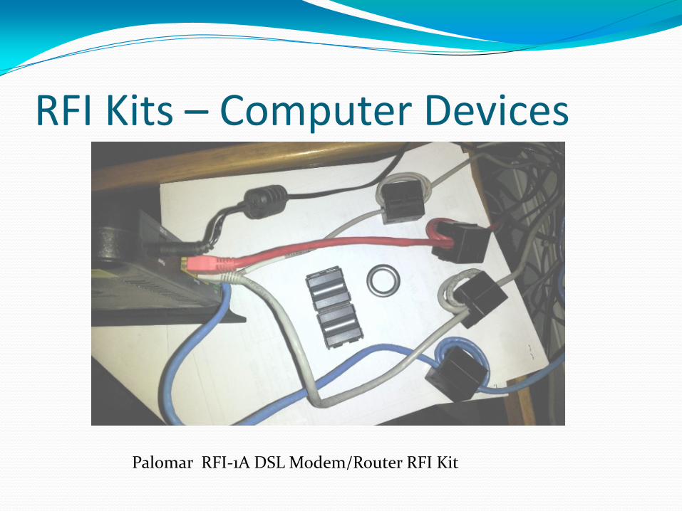
RFI Kits – Computer Devices
Palomar RFI-1A DSL Modem/Router RFI Kit
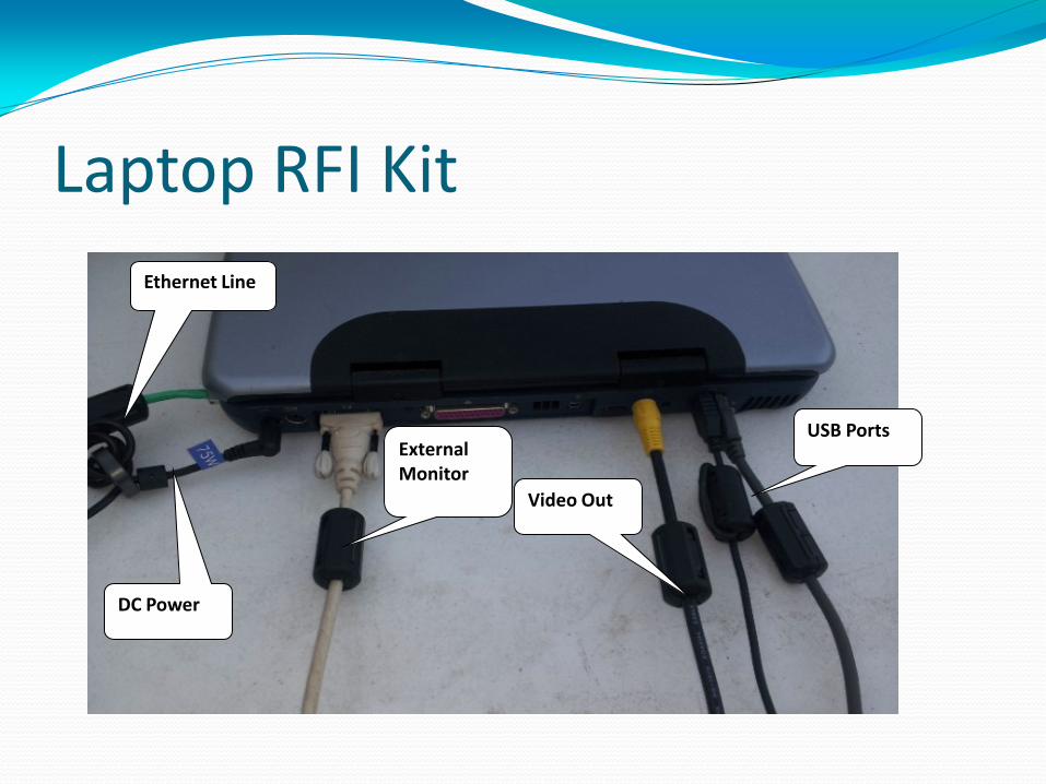
Laptop RFI Kit
USB Ports
Ethernet Line
DC Power
Video Out
External Monitor
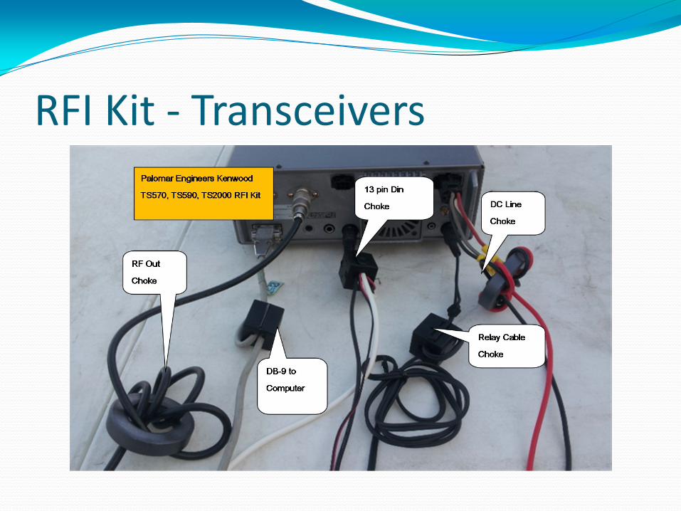
RFI Kit - Transceivers
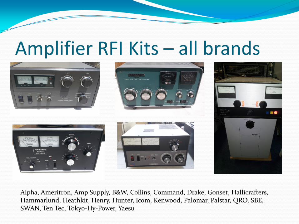
Amplifier RFI Kits – all brands
Alpha, Ameritron, Amp Supply, B&W, Collins, Command, Drake, Gonset, Hallicrafters, Hammarlund, Heathkit, Henry, Hunter, Icom, Kenwood, Palomar, Palstar, QRO, SBE, SWAN, Ten Tec, Tokyo-Hy-Power, Yaesu
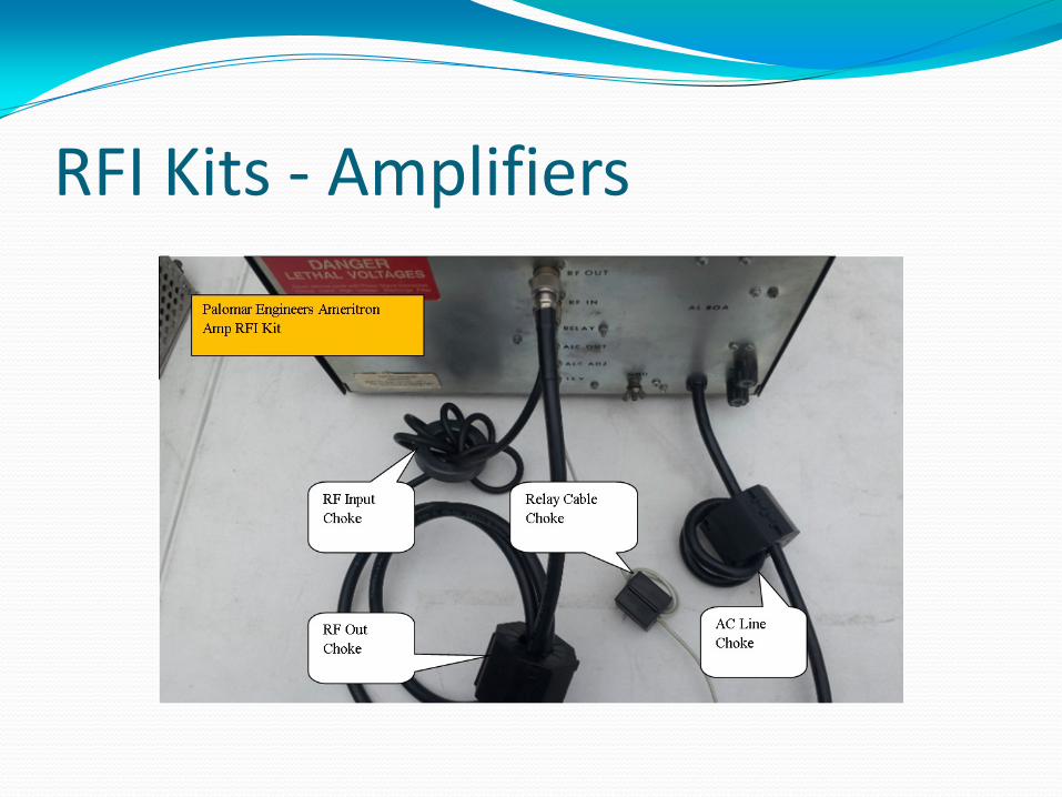
RFI Kits - Amplifiers
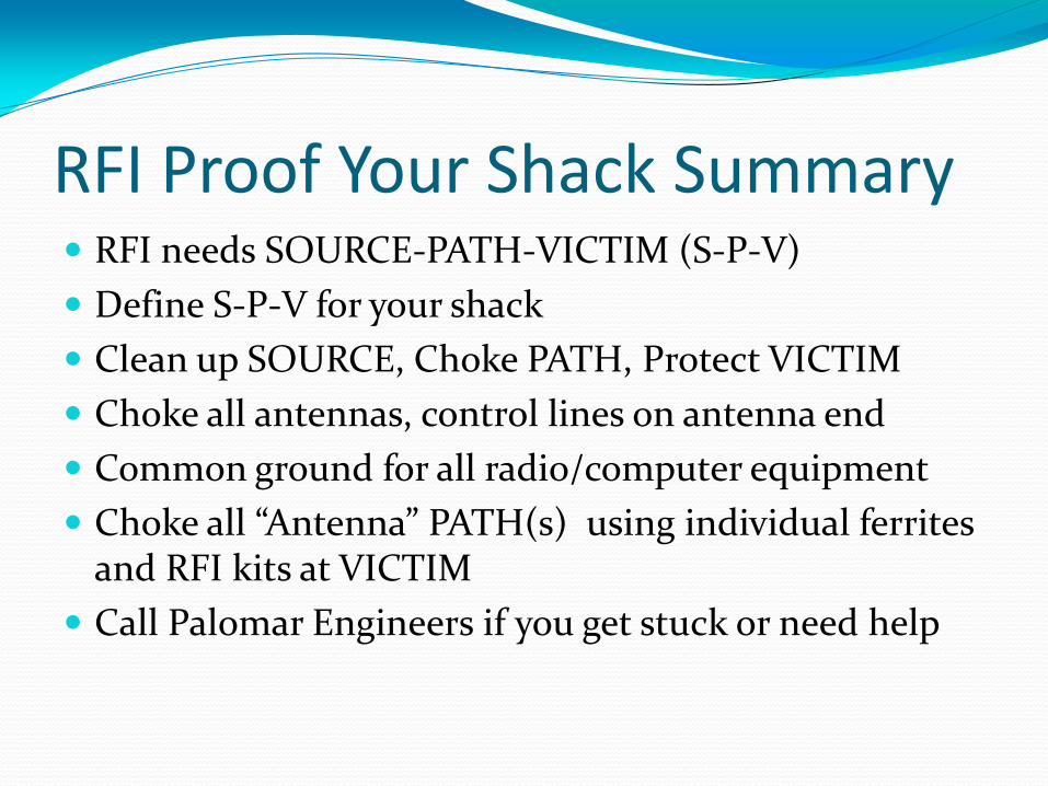
RFI Proof Your Shack Summary RFI needs SOURCE-PATH-VICTIM (S-P-V)
Define S-P-V for your shack
Clean up SOURCE, Choke PATH, Protect VICTIM
Choke all antennas, control lines on antenna end
Common ground for all radio/computer equipment
Choke all “Antenna” PATH(s) using individual ferrites and RFI kits at VICTIM
Call Palomar Engineers if you get stuck or need help

OR
Problem Isolation Source (transmitter or antenna”) – Path – Victim
Clean up your transmitter/shack first using techniques already discussed
Assess Neighbor’s Problem Faulty device (device acting as receiver when not
designed to be a radio receiver – e.g. Telephone)
Determine frequency of “transmitter” that is causing the problem (may not be on all bands – may not be you!)
Find the path (or paths) to the Victim (Receiver)
Choose the RFI choke/Kit for the frequency and path
Choke the path, protect the device (externally)!
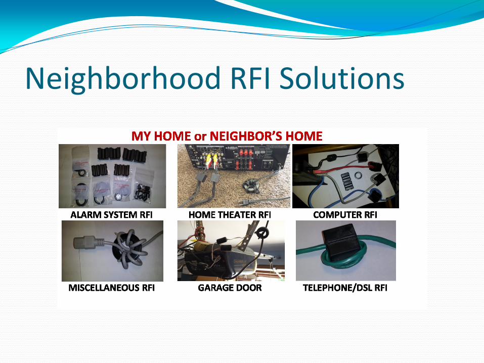
Neighborhood RFI Solutions
Neighborhood RFI Summary Assess S-P-V for the RFI – You or someone else?
If ham transmitter is the source: Use Palomar RFI solution kits for neighbor to install
Clean up SOURCE, Choke PATH, Protect VICTIM
Test RFI solutions for success
If non-ham source of RFI: Refer neighbor to Palomar Engineers for RFI solution
kits
Call Palomar Engineers if you get stuck or need help

Contact Info Website: www.Palomar-Engineers.com
Email: [email protected]
Phone: 760-747-3343
Bob Brehm, AK6R – Chief Engineer
This presentation available on the website.