Embed Size (px)
Citation preview
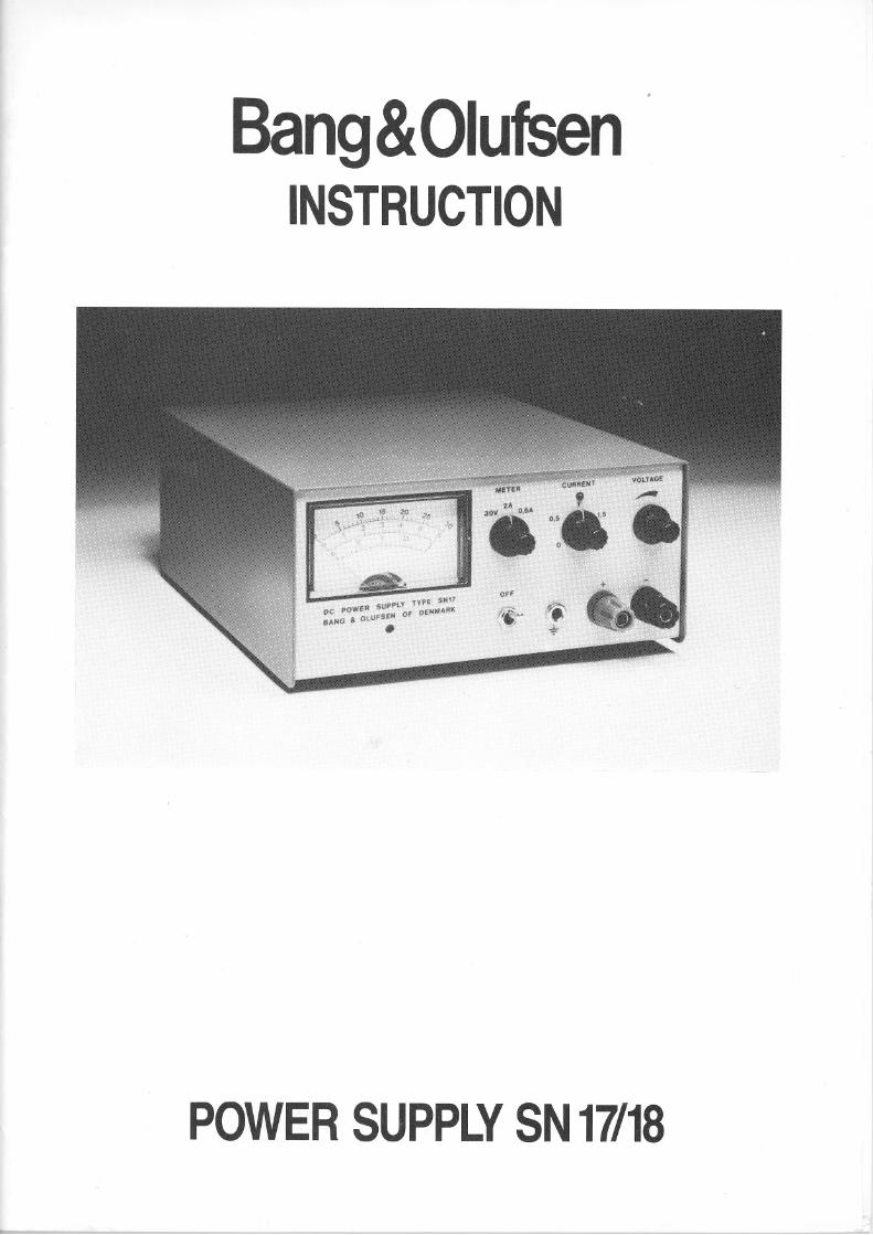
Bang&OlufsenINSTRUCTION
POWER SUPPLY SN 17/18
Bang&Olufsen
INTRODUCTION
2
The B&O Power Supply SN17 and SN18 are universally applicable powersupply units for application in workshops, schools, laboratories, industrialundertakings, etc.The two power supply units are functionally identicaI except as regardsvoltage and current range; in the SN17 it is 0...30 V/0 ...2 A and in theSN18 it is 0...60 V/0 ...1 A.Output voltage is adjusted through a multiturn potentiometer with anexchange ratio of approx. 1:6 or it may be resistance programmed,possibly through the "Remote" socketOutput impedance is very small, <2 mO at DC, and random noise isextremely low.Both power supply units are safeguarded against short-circuiting andoverloading, and they may be connected in series or in parallel withoutintroduction of equalizing resistors.
3TECHNICAL DATA Range
Remote
Adjustment at ±10% alteration ofmains voltage
Constant voltageConstant current
Adjustment at load 0 ...100%Constant voltageConstant current
Temperature co-efficient, constantvoltage
Bang&Olufsen0 30 V, 0 2 A (SN17)0 60 V, 0 1 A (SN18)Approx. 0.7 kO/V (SN17)Approx. 1.7 kO/V (SN18)
<±0.01%<±0.1 mA
<0.015%<±0.1 mA
<0.002%IOC
Output impedance <0.002 O at DC<0.2 O at 200 kHz
Ripple and noise, 20 Hz...200 kHz <100 f-lVrms (SN17)<200 f-lVrms (SN18)
Transient Response, load30 %-100 %-30 %, nominalvoltage ±10 mV
Indicator instrumentRanges
Accuracy
Mains connectionConsumption
Temperature range
Dimensions, W x D x H
Weight
Finish
Accessories
Subject to alterations
<50 f-lsec.
0 30 V, 0 2 A and 0 0.6 A (SN17)0 60 V, 0 1 A and 0 0.3 A (SN18)±2% of tun scale
110/220 V~ ±10%, 50/60 Hz5...90 W
163 x 210 x 80 mm
3.3 kg (7.3 Ibs)
Silver grey and blue enamel
1 manual
Bang&OlufsenAPPLICATION
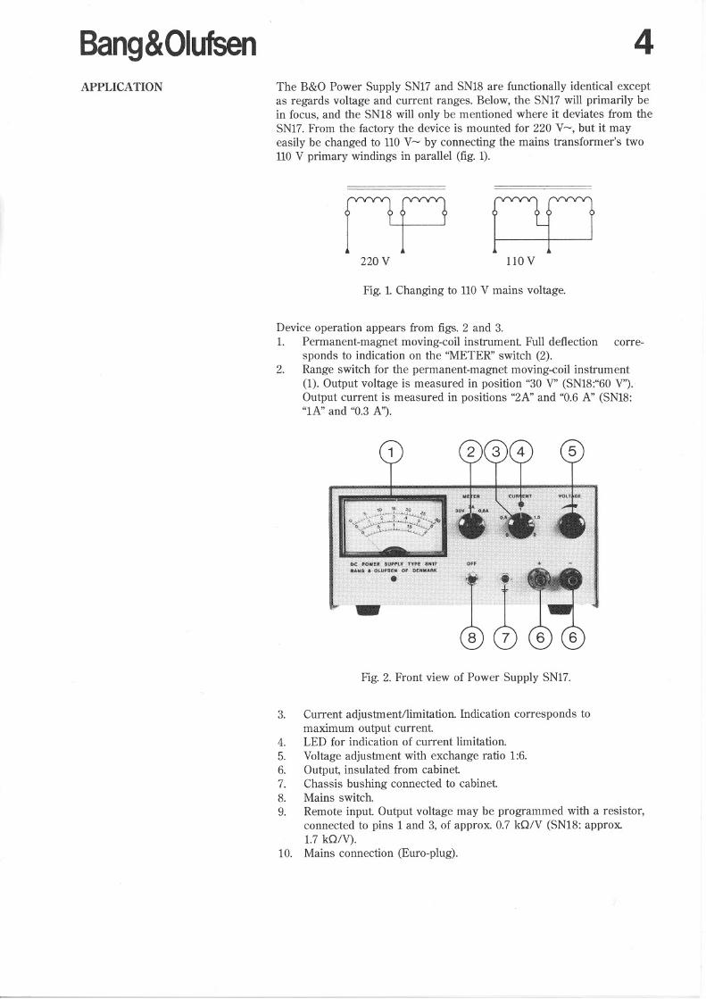
4The B&O Power Supply SN17 and SN18 are functionally identical exceptas regards voltage and current ranges. Below, the SN17 will primarily bein focus, and the SN18 will only be mentioned where it deviates from theSN17. From the factory the device is mounted for 220 V~, but it mayeasily be changed to 110 V~ by connecting the mains transformer's two110 V primary windings in parallel (fig. 1).
nov 1l0V
Fig.!. Changing to 110 V mains voltage.
Device operation appears from figs. 2 and 3.1. Permanent-magnet moving-coil instrument Full deftection corre
sponds to indication on the "METER" switch (2).2. Range switch for the permanent-magnet moving-coil instrument
(1). Output voltage is measured in position "30 V" (SN18:"60 V").
Output current is measured in positions "2A" and "0.6 A" (SN18:"lA" and "0.3 A").
Fig. 2. Front view of Power Supply SN17.
3. Current adjustment/limitation. lndication corresponds tomaximum output current
4. LED for indication of current limitation.
5. Voltage adjustment with exchange ratio 1:6.6. Output, insulated from cabinet7. Chassis bushing connected to cabinet8. Mains switch.9. Remote input Output voltage may be programmed with a resistor,
connected to pins 1 and 3, of approx. 0.7 kO/V (SN18: approx.1.7 kO/V).
10. Mains connection (Euro-plug).
5 Bang&Olufsen
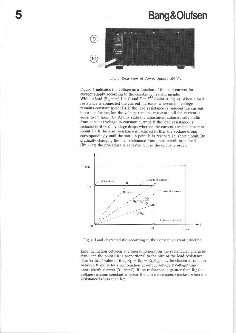
Fig. 3. Rear view of Power Supply SN 17.
Figure 4 indicates the voltage as a function of the load current forcurrent supply according to the constant-current principle.Without load (RL = 00) I = ° and E = EO (point A, fig. 4). When a loadresistance is connected the current increases whereas the voltageremains constant (point B). If the load resistance is reduced the currentincreases further, but the voltage remains constant until the current isequal to lO (point C). At this state the adjustment automatically shiftsfrom constant voltage to constant current If the load resistanee isreduced further the voltage drops whereas the current remains constant(point D). If the load resistance is reduced further the voltage dropscorrespondingly until the state in point K is reached, Le. short circuit By
grtdually changing the load resistance from short circuit to no-load(R = 00) the procedure is repeated, but in the opposite order.
E
D
Constant voltage
CBA (no-load)
--------------------------1IIIIll
l
Constant current IIIl
I
I
II
K (short circuit) I
E max.
0,0 lO lmax.
Fig. 4. Load characteristic according to the constant-current principle
Line inclination between any operating point on the rectangular characteristic and the point 0.0 is proportional to the size of the load resistance.The "critical" value of this, RL = RC = EO/IO, may be chosen at randombetween O and 00 by a combination of output voltage ("Voltage") andshort circuit current ("Current"). If the resistanee is greater than RC thevoltage remains constant whereas the current remains constant when theresistance is less than Re.
Bang&OlufsenExample 1. Constant voltage
Example 2. Constant current
Remote programming
Programming by potentiometer
6A test arrangement requires a supply voltage of 24 V, and at this voltageit has a current consumption of approx. 1 A. Because of the speciillcomponents in the arrangement the current consumption must not, incase of defects, exceed 1.5 A.The meter switch (2) is set at position "30 V".The "VOLTAGE" potentiometer (5) is adjusted to 24 V on the permanent-magnet moving-coilinstrument (1).With the meter switch in position "2 A" the output (6) isshort-circuited and the "CURRENT" potentiometer (3) is adjusted to 1.5A on the permanent-magnet moving-coil instrument The short circuit isremoved, and then the test arrangement may be connected.
The disengaging time for a small parcel of 100 mA fine fuses with slowacting characteristic is desired measured at a current of 400 mA. For themeasurement of the disengagement time an electronic counter isconnected. "Start/stop"-input maximum voltage, e.g. 10 V, mus t not beexceeded.
The "METER" switch is set at "30 V". The ''VOLTAGE'' potentiometer isadjusted to 10 V, this may be read on the permanent-magnet moving-coilinstrument The "METER" switch is set at "0.6 A". The output is shortcircuited, and the "CURRENT" potentiometer is adjusted to 0.4 A, whichmay be read on the instrument The short circuit is removed, and thenthe fuses may be connected directly over the output
The output voltage may be resistance programmed through the"REMOTE" input (9) at the rear of the device.The programming constant is approx. 0.7 kO/V (SN18: approx.1.7 kO IV).The resistance, corresponding to the desired voltage, is mounted in a 5pin DIN-piug between pins 1 and 3. When the plug is plugged in, thevoltage potentiometer (5) is switched off simultaneously.Note! The output voltage may momentarily go up to approx. 40 V (SN18:approx. 80 V), when the remote-plug is plugged in.
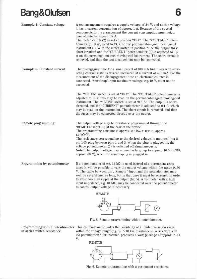
If a potentiometer of e.g. 22 kO is used instead of a permanent resistance it will be possible to vary the output voltage within the range 0...30V. The cable between the " Remote "-input and the potentiometer maywell be several metres long, but in that case it must be screened in orderto avoid too high ripple at the output (fig. 5). A voltmeter with a highinput impedance, e.g. 10 MO, may be connected over the potentiometerto control output voltage, if necessary.
REMOTE
Fig. 5. Remote programming with a potentiometer.
Programming with a potentiometer This combination provides the possibility of a limited variation rangein series with a resistanee within the voltage range (fig. 6). A 10 kO resistance in series with a 10
kO potentiometer, for instance, produces a voltage range of approx. 7...14V.
REMOTE
Fig. 6. Remote programming with a permanent resistance.
7Connection in parallel of two ormore SNl7 units.
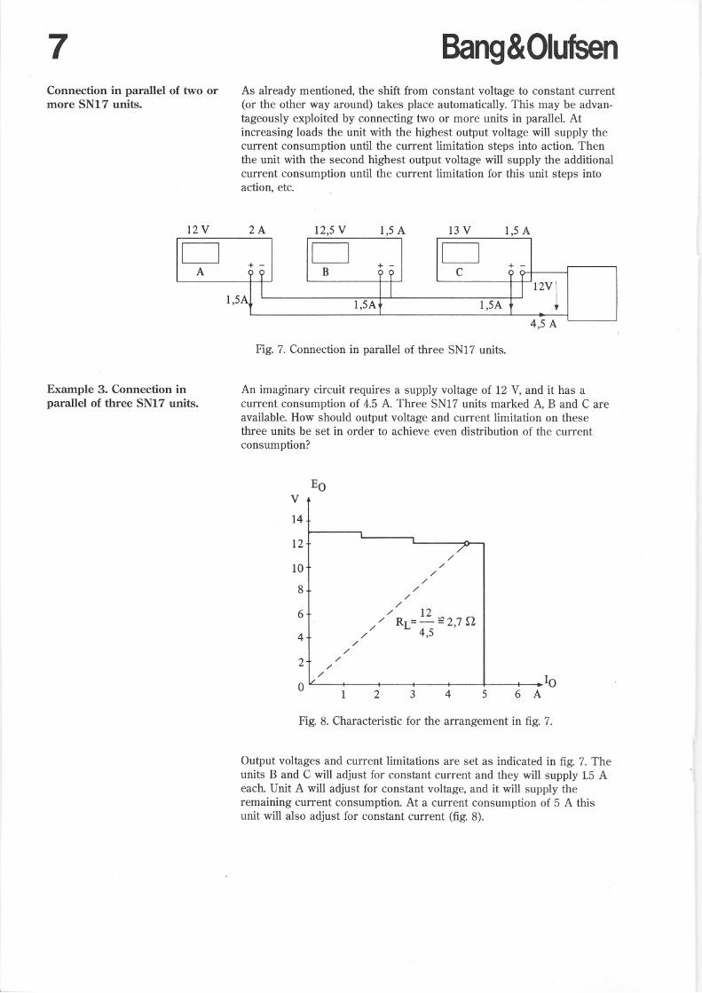
Bang&OlufsenAs already mentioned, the shift from constant voltage to constant current(or the other way around) takes place automatically. This may be advantageously exploited by connecting two or more units in parallel. Atincreasing loads the unit with the highest output voltage will supply thecurrent consumption until the current limitation steps into action. Thenthe unit with the second highest output voltage will supply the additionalcurrent consumption until the current limitation for this unit steps intoaction, etc.
12 V 2A 12,5 V 1,5 A 13 V 1,5 AD + -
D D+ -
+A ?B?C
I
II l2V!1,5A
1,5A1,5A~
4,5 A
Fig. 7. Connection in parallel of three SN17 units.
Example 3. Connection inparallel of three SNl7 units.
An imaginary circuit requires a supply voltage of 12 V, and it has acurrent consumption of 4.5 A. Three SN17 units marked A, B and C areavailable. How should output voltage and current limitation on thesethree units be set in order to achieve even distribution of the current
consumption?
EOV 1412 I
//
1: I//////6+
/12/ RL=- ~2,7 n/4+/4,5
/ /2+/
/L/ ,I I.10o
II I2
3456A
Fig. 8. Characteristic for the arrangement in fig. 7.
Output voltages and current limitations are set as indicated in fig. 7. Theunits B and C will adjust for constant current and they will supply 1.5 Aeach. Unit A will adjust for constant voltage, and it will supply theremaining current consumption. At a current consumption of 5 A thisunit will also adjust for constant current (fig. 8).
Bang&OlufsenConnection in series of twoor more SN17 units
Two or more SN17 units may be connected in series. Total voltagecompared to chassis must not exceed 300 V, however. The currentlimitation is set at the same value on all units.
8
30V
DA
1,5 A
+ -
30 V 1,5 A 20 V1,5A
D tolID ,B
C 9----l
80 V 11,2A
Fig. 9. Connection in series of three SN17 units.
Example 4. Connection in series of An imaginary circuit requires a supply voltage of 80 V, and it has athree SN17 units current consumption of approx. 1.2 A. The current consumption must not
exceed 1.5 A. Three SN17 units are available.
Two of the units, e.g. A and B, are set at 30 Vand the third unit is set atthe remaining voltage, 20 V. The current limitation is set at 1.5 A on allthree units. The units are connected as indicated in fig. 9.
Bipolar voltage supply If two SN17 units are connected in series, as indicated in fig. 10, a socalled bipolar voltage supply is achieved. The positive and negativeoutput voltages must be adjusted separately. This also applies to thecurrent limitation.
12 VDA
+ -
12 VDB
+ -
+12 V
Fig. 10. Bipolar voltagesupply.
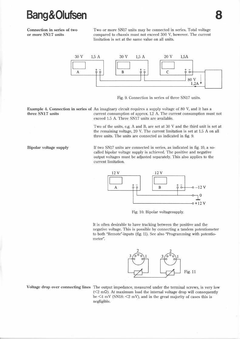
It is often desirable to have tracking between the positive and thenegative voltage. This is possible by connecting a tandem potentiometerto both "Remote"-inputs (fig. 11).See also "Programming with potentiometer".
2
Fig. 11
Voltage drop over connecting lines The output impedance, measured under the terminal screws, is very low«2 mG). At maximum load the internal voltage drop will consequentlybe <4 mV (SN18: <2 mV), and in the great majority of cases this isnegligible.
9 Bang&OlufsenWhen using test lines, on the other hand, the problem gains significantimportance. With a Cu cross-section of 0.75 mm2 the line resistance isapprox. 25 mO/m. With a line length of 1 m the voltage drop is thusincreased by 100 mV at 2 A. Consequently, this matter should be takeninto account, and it is best to use as short and heavy connecting lines aspossible.
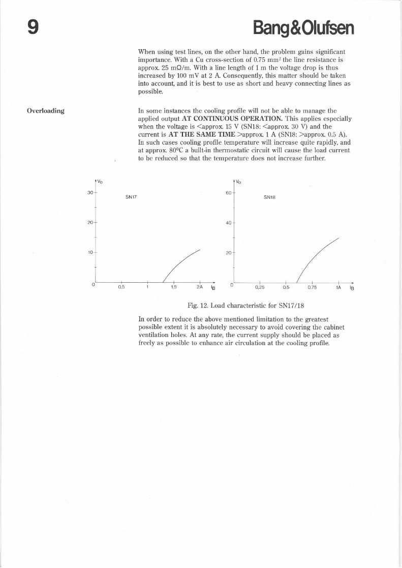
Overloading In some instances the cooling profile will not be able to manage theapplied output AT CONTINUOUS OPERATION. This applies especiallywhen the voltage is <approx. 15 V (SNI8: <approx. 30 V) and thecurrent is AT TRE SAME TIME >approx. 1 A (SNI8: >approx. 0.5 A).In such cases cooling profile temperature will increase quite rapidly, andat approx. 80GC a built-in thermostatic circuit will cause the load currentto be reduced so that the temperature does not increase further.
~+ wSN17 I SN18
~+ w
1A IB0,750,50,25°
2A IB1,50,5°
10+ ./ 20
Fig. 12. Load characteristic for SN17/18
In order to reduce the above mentioned limitation to the greatestpossible extent it is absolutely necessary to avoid covering the cabinetventilation holes. At any rate, the current supply should be placed asfreely as possible to enhance air circulation at the cooling profile.
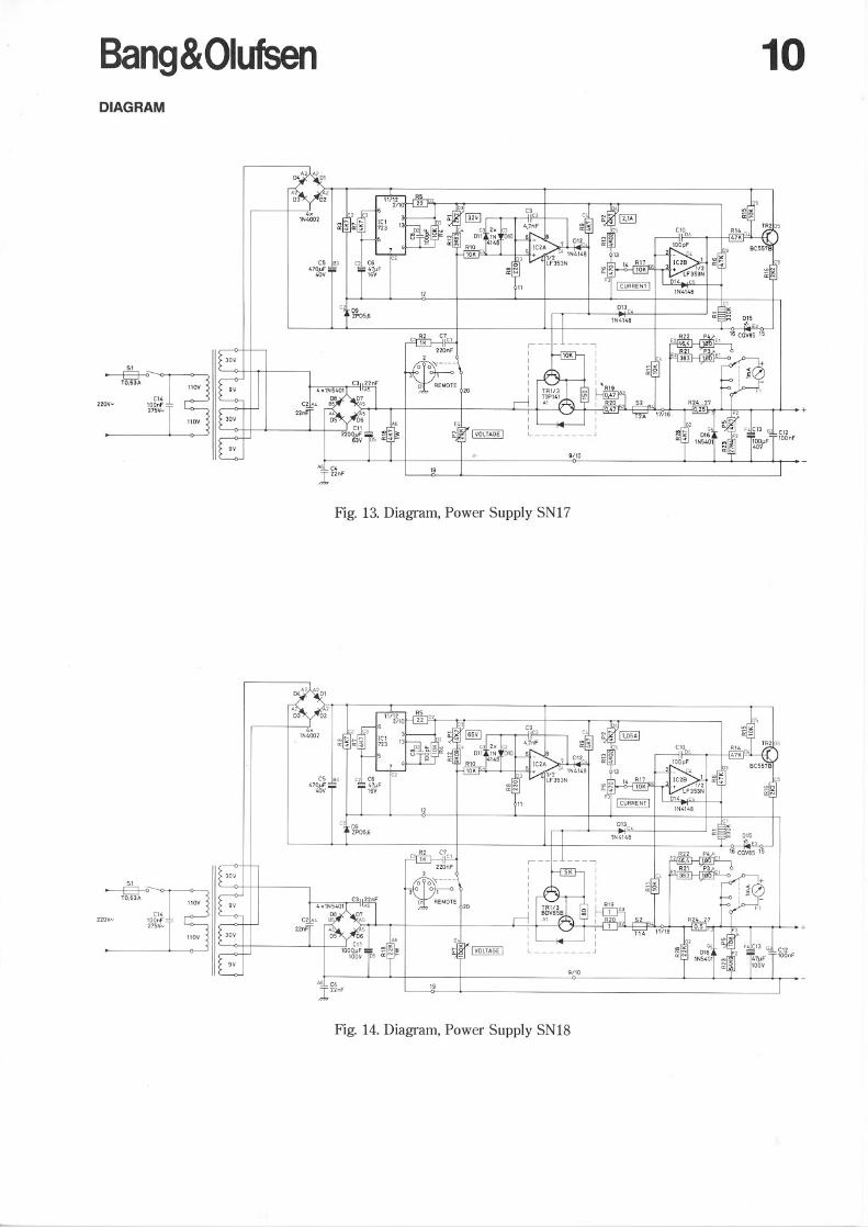
Bang&Olufsen 10DIAGRAM
+
C12
10QnF
9/10
19A.§LC4
122nF
Cl'100nF275V .•••
C2, 09ZP05,6
e5.Æ3 I cbL, C6470.uFT T 47..uF4QV 16V
12
Cl~ C,YCl
51
--E:J--OTO,63A
220V""
Fig. 13. Diagram, Power Supply SN17
51
--E:J--OTO,63A
Cl'2Z0VN lQOnF
275V'"
A§L C4l 22nF
Fig. 14. Diagram, Power Supply SN18

BANG & OLUFSENDK-7600 STRUERDENMARK TELEPHONE 07·851122 . TELEX 66529CABLE ADDRESS BANGOLUF09-84 3538607
a:w::la:f<n
<ti'"moa:-o:C!J
a:w"">-a:fC!Jo<Il
><Il"a:'""zwo;;;oWfZcc<L