Embed Size (px)
Citation preview
BLUESIM: A BLUETOOTH LAN ACCESS PROFILE SIMULATOR
By
SASIDHAR PARVATHAM
A THESIS PRESENTED TO THE GRADUATE SCHOOL OF THE UNIVERSITY OF FLORIDA IN PARTIAL FULFILLMENT
OF THE REQUIREMENTS FOR THE DEGREE OF MASTER OF SCIENCE
UNIVERSITY OF FLORIDA
2002

Copyright 2002
by
Sasidhar Parvatham

TO MY PARENTS

ACKNOWLEDGMENTS
I would like to extend my sincere gratitude to Dr. Helal for being the Chair of my
committee; and for guiding and motivating me through this thesis and also throughout my
graduate life here at University of Florida. I would also like to thank Dr. Frank and Dr.
Sanders for serving on my thesis committee and reviewing my work
I would like to thank Choonhwa Lee for his constant guidance and help through out
this thesis project. I would also like to express my thanks to my friends Madhav and Sree
for their encouragement and support. I also thank my friend Ameya for reviewing my
thesis and proofreading it. Last but not least I thank all my other friends here at CISE for
making my stay at the University a memorable one.
iv
TABLE OF CONTENTS
page
ACKNOWLEDGMENTS ................................................................................................. iv
LIST OF FIGURES ......................................................................................................... viii
ABSTRACT.........................................................................................................................x
CHAPTERS 1 INTRODUCTION ...........................................................................................................1
1.1 Motivation................................................................................................................. 2 1.2 Goal and Approach ................................................................................................... 2 1.3 Organization of Thesis.............................................................................................. 3
2 BLUETOOTH AND ITS PROFILES .............................................................................4
2.1 Bluetooth................................................................................................................... 4 2.2 Bluetooth Protocol Stack .......................................................................................... 6
2.2.1 Radio Layer..................................................................................................... 7 2.2.2 Baseband Layer............................................................................................... 7 2.2.3 The Link Controller ........................................................................................ 7 2.2.4 The Link Manager........................................................................................... 7 2.2.5 Host Controller Interface................................................................................. 8 2.2.6 Logical Link Controller and Adaptation Protocol .......................................... 8 2.2.7 RFCOMM ....................................................................................................... 8 2.2.8 The Service Discovery Protocol...................................................................... 9
2.3 Bluetooth Profiles ..................................................................................................... 9 2.3.1 Intercom Profile .............................................................................................. 9 2.3.2 Cordless Telephony Profile............................................................................. 9 2.3.3 Headset Profile .............................................................................................. 10 2.3.4 Dialup Networking Profile............................................................................ 11 2.3.5 Fax Profile..................................................................................................... 11 2.3.6 LAN Access Profile ...................................................................................... 11 2.3.7 File Transfer Profile ...................................................................................... 12 2.3.8 Object Push Profile ....................................................................................... 12 2.3.9 Synchronization Profile................................................................................. 12
v
3 LAN ACCESS PROFILE..............................................................................................13
3.1 Protocol Stack and Entities Used............................................................................ 15 3.2 Profile Operation/Fundamentals ............................................................................. 15 3.3 PPP Operation......................................................................................................... 16
3.3.1 Initialize PPP................................................................................................. 16 3.3.2 Establish PPP Connection............................................................................. 16 3.3.3 PPP Authentication Protocols ....................................................................... 16 3.3.4 Disconnect PPP Connection.......................................................................... 17 3.3.5 Shutdown PPP............................................................................................... 18
3.4 RFCOMM Operation .............................................................................................. 18 3.5 Service Discovery ................................................................................................... 18 3.6 L2CAP .................................................................................................................... 19 3.7 LMP ........................................................................................................................ 19 3.8 Link Control............................................................................................................ 19 3.9 Management Entity Procedures .............................................................................. 20
3.9.1 Link Establishment ....................................................................................... 20 3.9.2 Maximum Number of Users.......................................................................... 21
4 BACKGROUND AND RELATED WORK .................................................................22
4.1 Network Simulator.................................................................................................. 22 4.1.1 Two Languages ............................................................................................. 23 4.1.2 Discrete Event Scheduler .............................................................................. 26 4.1.3 Packet Format ............................................................................................... 27 4.1.4 Node and Routing ......................................................................................... 28
4.2 BlueHoc Simulator.................................................................................................. 29 4.2.1 Device Discovery and Paging ....................................................................... 31 4.2.2 Connection Establishment in BlueHoc ......................................................... 31
4.2.2.1 LMP signaling......................................................................................31 4.2.2.2 L2CAP connection establishment........................................................32 4.2.2.3 QoS mapping .......................................................................................32
4.2.3 Logical Link Control and Adaptation Protocol Simulation .......................... 33 4.3 LAPSim Simulator.................................................................................................. 33
5 BLUESIM......................................................................................................................36
5.1 Connection Establishment ...................................................................................... 37 5.2 Modifications to Bluetooth Host............................................................................. 39 5.3 Modifications to L2CAP......................................................................................... 39 5.4 RFCOMM Layer..................................................................................................... 40 5.5 PPP Layer................................................................................................................ 41 5.6 BlueSim Node Structure ......................................................................................... 42 5.7 Routing.................................................................................................................... 43 5.8 Experiments Conducted .......................................................................................... 43
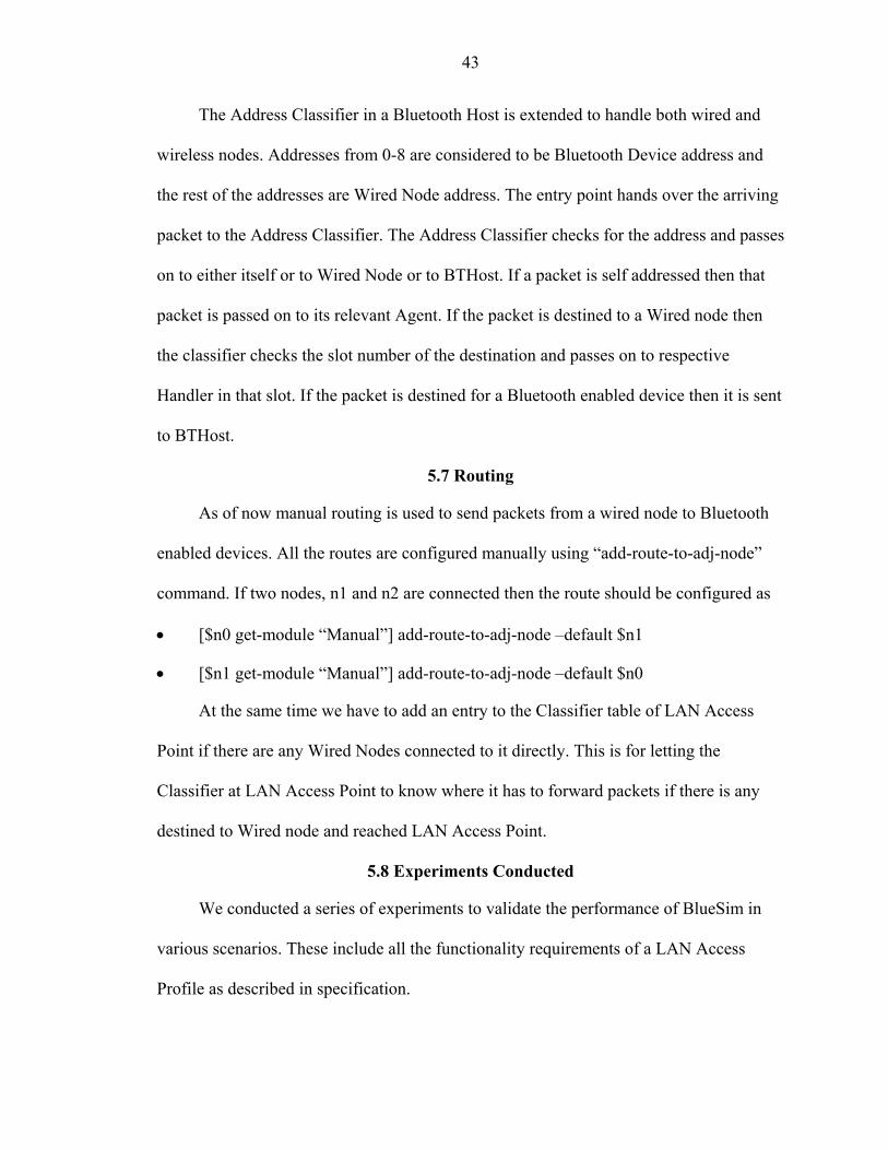
5.8.1 LAN Access Point Simulation – Single Node .............................................. 44 5.8.2 LAN Access Point – Multiple Nodes............................................................ 44
vi
5.8.3 Piconet Simulation ........................................................................................ 45 5.8.4 LAN Access Point as an Intermediate Node................................................. 46
5.9 Simulation Results .................................................................................................. 47 5.9.1 Simulation Output ......................................................................................... 47 5.9.2 Delay vs Number of Nodes ........................................................................... 48 5.9.3 Comparison of BlueHoc and BlueSim.......................................................... 49 5.9.4 Delay Distribution......................................................................................... 50
6 CONCLUSION AND FUTURE WORK ......................................................................52
6.1 Conclusion .............................................................................................................. 52 6.2 Future Work ............................................................................................................ 52 6.3 Suggested Modifications......................................................................................... 53
6.3.1 Automate Wired Network Creation .............................................................. 53 6.3.2 Bi-directional Traffic .................................................................................... 53 6.3.3 Master-Slave Switching Roles ...................................................................... 54 6.3.4 Service Discovery ......................................................................................... 55
LIST OF REFERENCES...................................................................................................56
BIOGRAPHICAL SKETCH .............................................................................................58
vii

LIST OF FIGURES
Figure page
2-1. Bluetooth protocol stack...............................................................................................6
2-2. Bluetooth profile structure..........................................................................................10
3-1. LAN Access Profile....................................................................................................14
4-1. User’s view of NS.......................................................................................................22
4-2. Connection between OTcl and C++ ...........................................................................24
4-3. Tcl interpreter .............................................................................................................25
4-4. Event scheduler...........................................................................................................26
4-5. Packet format..............................................................................................................27
4-6. Node and routing ........................................................................................................28
4-7. BlueHoc node structure ..............................................................................................30
4-8. LAPSim node structure ..............................................................................................34
5-1. BlueHoc connection establishment ............................................................................37
5-2. BlueSim connection establishment.............................................................................38
5-3. RFCOMM connection establishment .........................................................................40
5-4. PPP connection establishment ....................................................................................41
5-5. BlueSim node structure ..............................................................................................42
5-6. A Single Bluetooth accessing LAN services..............................................................44
5-7. Multiple Bluetooth devices accessing LAN services .................................................45
5-8. BlueSim piconet simulation........................................................................................46
5-9. LAN Access Point as an intermediate node ...............................................................46
viii

5-10. BlueSim connection establishment...........................................................................47
5-11. Delay vs number of nodes ........................................................................................48
5-12. BlueHoc vs BlueSim ................................................................................................50
5-13. Delay distribution .....................................................................................................51
ix

Abstract of Thesis Presented to the Graduate School
of the University of Florida in Partial Fulfillment of the Requirements for the Degree of Master of Science
BLUESIM: A BLUETOOTH LAN ACCESS PROFILE
By
Sasidhar Parvatham
December 2002 Chair: Abdelsalam Helal Department: Computer and Information Sciences and Engineering
Improved technology in computer and peripheral manufacturing has reduced the
size of computing devices remarkably, making it easier to carry them to any place. At the
same time the universal presence of wireless networks and technologies like distributed
and mobile computing made it easier to access data from any place and any time. This
access of data from any place and any time using a new class of portable, intelligent and
wireless mobile devices is pervasive computing. Pervasive computing is the future of the
information technology industry. Pervasive computing provides a framework for mobile
commerce.
Pervasive computing extends the boundaries of electronic commerce. The ability to
access data from any time and any place makes it possible to deliver electronic commerce
to consumers anywhere. This use of mobile devices such as a mobile phone or PDA to
perform a transaction electronically is called mobile commerce. There have been
numerous products on the market like IEEE 802.11, Bluetooth and HomeRF to enable
x

mobile commerce. The product IEEE 802.11 is intended for Wireless LAN
Communication, HomeRF is intended for Home Networking and Bluetooth is intended as
cable replacement. Our device of interest is Bluetooth.
Bluetooth supports a wide number of profiles. A LAN Access Profile of Bluetooth
can enable mobile commerce applications. Bluetooth has been touted excitedly as a
cheap, low-power mobile commerce enabler. Because Bluetooth is a cable replacement
technology, Bluetooth’s suitability for mobile commerce scenarios must be verified.
Hence a simulator is needed that can simulate various mobile commerce scenarios.
Few software simulators are able to simulate Bluetooth stack. BlueHoc is one
available simulator that captures lower layers of Bluetooth. It was built on the widely
know network simulator. Though BlueHoc simulates lower layers excellently, it does not
simulate any profiles. Hence it is not suitable for testing the Mobile Commerce scenarios.
LAPSim is another available simulator that simulates a LAN Access Point (LAP).
It implements in detail the upper layers of Bluetooth LAP stack, including PPP,
RFCOMM and L2CAP. It tries to capture characteristics of lower layers by performing
macro-simulation. To better understand the full impact of Bluetooth on future pervasive
computing applications, simulation of the whole Bluetooth LAN Access Profile is
needed.
For this study, we built a new Bluetooth simulator to simulate various mobile
commerce scenarios. We simulated a LAN Access Profile by extending the BlueHoc
simulator. We simulated the PPP and RFCOMM layer. We also extended the
functionality of master to a LAN access point. We simulated variety of scenarios.
xi
CHAPTER 1 INTRODUCTION
The importance of pervasive computing [Mahadev 2001] is rapidly increasing with
the ubiquitous presence of mobile computing, computer networks and wireless
communications. Pervasive means widespread. Thus pervasive computing means
computing that has become available everywhere. For pervasive computing to happen,
the computing infrastructure should become more and more ubiquitous. Because of
technological breakthroughs, pervasive computing will become the key to information
technology over the next few years. Pervasive computing lays the foundation for mobile
commerce.
Mobile commerce [Varshney, Vetter and Kalakota 2000] is electronic commerce
that takes place in a mobile environment. Mobile commerce carries out financial
transactions electronically using a mobile network. New opportunities for mobile
commerce deployment will emerge with the fast growth and universal presence of
wireless and mobile networks. A direct correlation exists between pervasive computing
and mobile commerce. Without the former, the latter cannot happen; and without the
incentive of the latter, the former will not happen quickly enough.
Vast numbers of mobile devices and technologies enable mobile commerce
[Varshney and Vetter 2001]. These mobile devices give people access to information at
any time and any place. Each device has its own advantages and disadvantages. There is
a need to validate the performance of such devices in the various scenarios where mobile
commerce occurs. Bluetooth is one of the technologies that enable mobile commerce. In
1

2
this thesis we attempt to validate Bluetooth’s performance in some of the mobile
commerce scenarios.
1.1 Motivation
Potentially unlimited numbers of mobile commerce applications exist [Varshney
2001]. Also, various devices enable mobile commerce. Bluetooth is one device that
enables mobile commerce. Bluetooth, a cable replacement chip, supports a wide variety
of profiles. Some of the profiles supported by Bluetooth include LAN Access Profile,
Cordless Telephony Profile, Intercom Profile, Headset Profile, Dialup Networking
Profile, Fax Profile, File Transfer Profile, Object Push Profile, and Synchronization
Profile. LAN Access Profile is the profile that enables mobile commerce. Bluetooth is a
cable replacement technology with limited range and bandwidth. Its performance in
various mobile commerce scenarios is questionable. A mechanism is needed that can
verify the performance of Bluetooth in a multitude of mobile commerce scenarios.
1.2 Goal and Approach
Given the need for a mechanism to verify Bluetooth’s suitability for mobile
commerce applications, we built a simulator to validate Bluetooth’s performance in
various mobile commerce scenarios. To simulate various scenarios we needed a complete
LAN Access Profile simulator, the profile that captures mobile commerce applications.
We did not have such a simulator. We did have BlueHoc for simulating lower layers, and
LAPSim for simulating upper layers. Each of these simulators is incomplete. So we set at
to build a simulator by combining the two. We started by modifying BlueHoc and adding
the upper layers. We also upgraded the master node of BlueHoc to a LAN access point.
3
1.3 Organization of Thesis
Chapter 2 covers the detailed architecture of Bluetooth and the profiles it supports.
Chapter 3 describes the LAN Access Profile in detail. We cover the profile features and
also the operations of various layers. Chapter 4 explains the network simulator, BlueHoc,
and LAPSim. Chapter 5 describes the implementation details and the results obtained
from simulating some of the scenarios. Chapter 6 gives conclusions and suggests future
work.
CHAPTER 2 BLUETOOTH AND ITS PROFILES
With the advent of numerous technologies, Computers have been transformed from
mere computing devices to high performance, multiuse, complex devices. Huge numbers
of peripherals are available to connect to computers. Despite our best efforts to hide
them, numerous cables are seen everywhere in the proximity of computers. With each
device comes a cable to connect it. In a plugged-in society, plugging things in has
become a big hassle [Muller 2000].
Bluetooth [Bray and Sturman 2000] is a low-cost, low-power, short-range radio
technology, originally developed to replace cables that connect various devices. With
Bluetooth, people will no longer need to connect, plug into, install, enable or configure
computer peripherals. Through a ubiquitous standardized communication subsystem,
devices will communicate seamlessly. In this chapter we cover Bluetooth architecture and
its profiles.
2.1 Bluetooth
Bluetooth wireless technology is the result of a study examining alternatives to the
cables that connect mobile devices with peripherals. Bluetooth is expected to unify the
telecommunications and computing industries. Major corporations formed a Bluetooth
special interest group to work together toward defining open Bluetooth technical
specifications. The main reason for this effort was that consumers are more likely to
adopt an open standard or technology (that they can get from different manufacturers)
than a proprietary restricted one (that will limit them to only a handful vendors).
4
5
Bluetooth is a standard small, cheap, low-power radio chip to be plugged into
computers, printers, mobile phones, etc. A Bluetooth chip is designed to replace cables
by taking the information normally carried by cables, and transmitting it to a receiver
Bluetooth chip, which is then carried on to either a phone or a computer. Bluetooth
operates in the unlicensed 2.4 GHz ISM band. It uses frequency hopping spread-spectrum
transmission. The Bluetooth chip transmits and receives on 79 different hop frequencies
from 2402 MHz to 2480 MHz, switching from one frequency to another at the rate of
1600 times a second in a pseudo random fashion. It uses Gaussian frequency shift key
modulation with a maximum data rate of 721 Kbits/sec and a range of 10 meters.
Bluetooth devices can operate in two modes: master or slave. Master is the device that
sets the frequency-hopping sequence. Slaves synchronize to the Master in time and
frequency by following the master’s hopping sequence. A collection of slave devices
operating together with one common master is referred to as a piconet. Up to seven slaves
are allowed in a piconet. However piconets can be linked into a scatternet, where some
devices are members of more than one piconet. It is not possible to have a device that is
the master of two different piconets because all slaves are synchronized to the masters
hop frequency. The Bluetooth Specification allows for three different types of radio
powers. These power classes allow Bluetooth devices to connect at different ranges, with
the class consuming high power providing a range of 100 meters and the class consuming
least power providing a range of 10 meters. Bluetooth allows time-critical data
communication (such as that required for voice or audio) and high-speed, time-insensitive
packet data communication. For this, two different links are defined for any two devices.
6
These are Synchronous Connection Oriented (SCO) links for voice communication and
Asynchronous Connectionless (ACL) links for data communication.
2.2 Bluetooth Protocol Stack
Bluetooth stack [Bray and Sturman 2000] is defined in a series of layers. A key
feature of Bluetooth specification is that it aims to allow devices from lots of different
manufacturers to work with one another. To this end, Bluetooth does not just define the
radio system, it also defines a software stack to enable applications to find other
Bluetooth devices in the area, discover what services they can offer, and use those
services.
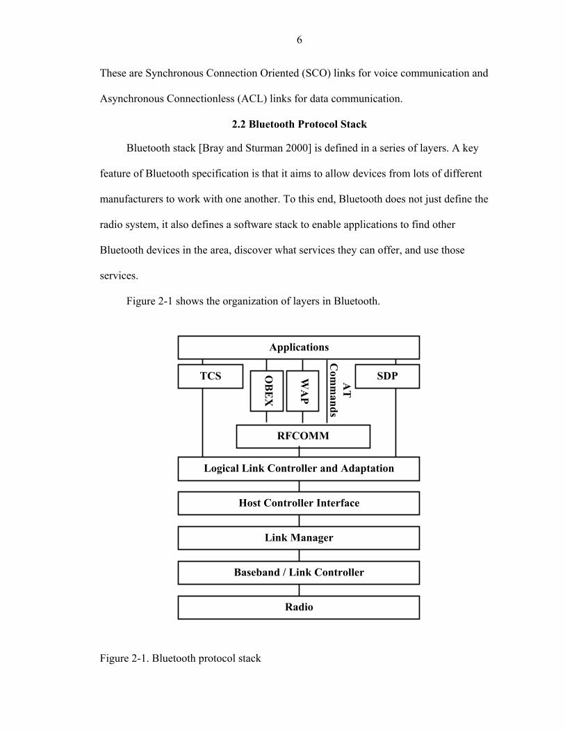
Figure 2-1 shows the organization of layers in Bluetooth.
AT
C
omm
ands
Logical Link Controller and Adaptation
Host Controller Interface
Link Manager
Baseband / Link Controller
RFCOMM
WA
P
TCS SDP OB
EX
Applications
Radio
Figure 2-1. Bluetooth protocol stack
7
2.2.1 Radio Layer
The Bluetooth Radio is the lowest defined layer of the Bluetooth specification. It
defines the requirements of the Bluetooth transceiver device operating in the 2.4 GHz
ISM band. This band is used by a plethora of devices and hence is not free of
interference. To cope up with this environment Bluetooth specifies several techniques
like frequency hopping, adaptive power control, and short data packets.
2.2.2 Baseband Layer
The Baseband is the physical layer of Bluetooth. The Baseband is responsible for
channel coding and decoding and low level timing control and management of the link
within the domain of a single data packet transfer. It manages physical channels and links
apart from other services like error correction, data whitening, hop selection and
Bluetooth security. This layer lies on top of the Bluetooth radio layer in the Bluetooth
stack.
2.2.3 The Link Controller
The Link Controller (LC) is responsible for carrying out link level operations over
several data packet durations in response to a higher level of commands from the link
manager (LM). The local and remote LC entities will manage packet-by-packet process
of establishing the link once commanded by LM and will maintain the link once
established. This layer lies above the Baseband layer.
2.2.4 The Link Manager
The host drives a Bluetooth device through Host Controller Interface (HCI)
commands, but it is the Link Manager (LM) that translates those commands into
operations at Baseband level. The link manager carries out link setup, authentication, link
configuration and other protocols. It discovers other remote LMs and communicates with
8
them via the Link Manager Protocol (LMP). To provide its services LM uses the services
of the underlying Link Controller (LC).
2.2.5 Host Controller Interface
Some Bluetooth Systems will have the Baseband and Link Manager on one
processor with higher layers such as L2CAP, SDP and RFCOMM, and applications
running on a separate host processor. By separating higher layers from lower layers
Bluetooth devices can perform with low memory and processor reducing the cost. In
these types of systems, an interface is needed between the higher and the lower layers.
Bluetooth standard defines the Host Controller Interface (HCI). By making this a
standard interface, it is possible to mix and match higher and lower layers.
2.2.6 Logical Link Controller and Adaptation Protocol
Logical Link Controller and Adaptation Protocol (L2CAP) takes data from higher
layers of the Bluetooth stack and applications and sends it to lower layers of stack.
L2CAP sends packets to either HCI, or in a host-less system, L2CAP sends directly to the
Link Manager (LM). Functions provided by L2CAP are multiplexing between different
higher layer protocols, segmentation and reassembly to allow transfer of larger packets
than the lower layers, group management, providing one-way transmission to a group of
other Bluetooth devices, and Quality of Service Management for higher layer protocols.
L2CAP allows both Connection-oriented and Connectionless data service to upper layers.
Voice and Audio traffic does not make use of L2CAP layer.
2.2.7 RFCOMM
RFCOMM is a simple transport protocol, which provides emulation of serial cable
over L2CAP. The protocol is based on the ETSI standard TS 07.10. Only a subset of TS
07.10 standard is used. RFCOMM relies on the Bluetooth Baseband to provide reliable
9
in-sequence delivery of the byte-stream. It does not have ability to correct errors. The
RFCOMM protocol has a support for up to 60 simultaneous connections between two BT
devices.
2.2.8 The Service Discovery Protocol
The Service Discovery Protocol (SDP) provides a means for applications to
discover which services are available and to determine the characteristics of those
available services. Unlike LAN where you know what devices are connected ahead, it is
not the case with the Bluetooth piconets. Bluetooth devices enter and leave piconets quite
often. There is no way to tell which devices are connected to it. Bluetooth SDP is the
protocol, which discovers the devices in the vicinity and will let you know what services
are being offered.
2.3 Bluetooth Profiles
The Bluetooth SIG has identified various usage models, each of which has a
supporting “profile” that defines the protocol and features the usage model draw upon for
implementation.
2.3.1 Intercom Profile
The Intercom Profile supports the usage scenarios that require a direct speech link
between two Bluetooth devices, such as two cellular phone users engaged in a speech call
on a Bluetooth connection. Even though the call is a direct phone-to-phone connection
using Bluetooth wireless technology, the link is established using telephony-based
signaling.
2.3.2 Cordless Telephony Profile
In addition to the intercom application, the 3-in-1 phone usage model can support
cordless-only telephony or cordless telephony services available through a multimedia

10
PC, further extending the usefulness of Bluetooth wireless Technology in a residential or
small office environment. The cordless telephony profile defines the procedures for and
the features associated with making calls via the base station and placing direct intercom
calls between two terminals.
Generic Access Profile TCS BIN Profiles
Serial Port Profile
Intercom Profile
Generic Object Exchange Profile
Service Discovery Profile
Cordless Telephony Profile
File Transfer Profile
Object Push Profile
Synchronization Profile
Dialup Networking Profile
Fax Profile
Headset Profile
LAN Access Profile
Figure 2-2. Bluetooth profile structure
2.3.3 Headset Profile
The Headset profile defines the protocols and procedures for the usage model know
as “Ultimate Headset”, which can be implemented by such devices as cellular phones and
personal computers. The headset can act as a device’s audio input and output interface for
the purpose of increasing the user’s freedom of movement while maintaining call
11
privacy. The headset must be able to send AT-commands and receive result codes. This
ability allows the headset to answer incoming calls and then terminate them without the
user having to physically manipulate the telephone handset.
2.3.4 Dialup Networking Profile
The Dialup Networking Profile defines the protocols and procedures used by the
devices such as modems and cellular phones for implementing the usage model called
“Internet Bridge”. Among the possible scenarios for this model are the use of a cellular
phone as a wireless modem for connecting a computer to a dialup Internet access server,
or the use of a cellular phone or modem by a computer to receive data.
2.3.5 Fax Profile
The fax profile defines the protocols and procedures used by devices implementing
the fax part of the usage model called “Data Access Points, Wide Area Networks.” A
computer may use a Bluetooth enabled cellular phone or modem as a wireless fax-
modem to send or receive fax messages.
2.3.6 LAN Access Profile
The LAN Access Profile defines how devices using Bluetooth wireless technology
can access the services of a LAN using the point-to-point Protocol (PPP) over RFCOMM
and use the same PPP mechanisms to network two devices using Bluetooth wireless
technology. In this usage model, multiple data terminals (DTs) use a LAN access point
(LAP) as a wireless connection to a local area network (LAN). Once connected, the data
terminals operate as if they are connected to a LAN via dialup networking and can access
all the services provided by the LAN.
12
2.3.7 File Transfer Profile
The File Transfer Profile supports the file transfer usage model, which offers the
ability to transfer data objects from one Bluetooth device to another. These devices would
typically be PCs, smart phones, or PDAs. This usage model also offers users the ability to
browse the contents of folders that reside on a remote device. New folders can be created
and others deleted. Entire folders, directories, or streaming media formats can be
transferred between devices.
2.3.8 Object Push Profile
The Object Push Profile allows a Bluetooth device to push an object to the inbox of
another Bluetooth device. The object might be either a business card or an appointment.
2.3.9 Synchronization Profile
The Synchronization Profile defines requirements for the protocols and procedures
used by applications providing the Synchronization usage model. This model provides
device-to-device synchronization of personal information management (PIM)
information.

CHAPTER 3 LAN ACCESS PROFILE
In this chapter we discuss the Bluetooth profile of our interest, the LAN Access
Profile. The LAN Access Profile defines how Bluetooth enabled devices can access the
services of a LAN using PPP. Also, this profile shows how the same PPP mechanisms are
used to form a network consisting of two Bluetooth enabled devices. The LAN Access
Profile allows a Bluetooth enabled device to access a fixed network via a Bluetooth Link
to a LAN Access Point (LAP). Such a device could be used in many scenarios: as a
Personal work area access point, replacing the network cable and allowing mobility with
in the range of an access point; as a shared access point in a room, allowing fast
establishment of network connections; or as a public access point, allowing easy access to
information and services.
Bluetooth specification specifies two roles for Bluetooth devices in this profile,
LAN Access Point (LAP) and Data Terminal (DT). LAN Access Point (LAP) is the
Bluetooth device that provides access to a LAN. The LAP provides the services of a PPP
Server. The PPP connection is carried over RFCOMM. RFCOMM is used to transport
the PPP packets and it can also be used for flow control of the PPP data stream. Data
Terminal (DT), this is the device that uses the services of the LAP. The DT is a PPP
client. It forms a PPP connection with a LAP in order to gain access to a LAN.
13
14
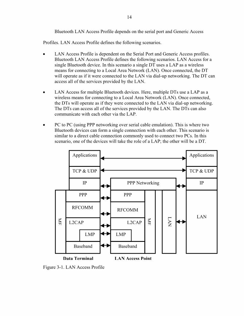
Bluetooth LAN Access Profile depends on the serial port and Generic Access
Profiles. LAN Access Profile defines the following scenarios.
• LAN Access Profile is dependent on the Serial Port and Generic Access profiles. Bluetooth LAN Access Profile defines the following scenarios. LAN Access for a single Bluetooth device. In this scenario a single DT uses a LAP as a wireless means for connecting to a Local Area Network (LAN). Once connected, the DT will operate as if it were connected to the LAN via dial-up networking. The DT can access all of the services provided by the LAN.
• LAN Access for multiple Bluetooth devices. Here, multiple DTs use a LAP as a wireless means for connecting to a Local Area Network (LAN). Once connected, the DTs will operate as if they were connected to the LAN via dial-up networking. The DTs can access all of the services provided by the LAN. The DTs can also communicate with each other via the LAP.
• PC to PC (using PPP networking over serial cable emulation). This is where two Bluetooth devices can form a single connection with each other. This scenario is similar to a direct cable connection commonly used to connect two PCs. In this scenario, one of the devices will take the role of a LAP; the other will be a DT.
RFCOMMRFCOMM
LMP LMP
L2CAPL2CAP
PPP PPP
LAN LAN
ME
PPP Networking IP IP
TCP & UDPTCP & UDP
ApplicationsApplications
Baseband Baseband
ME
Data Terminal LAN Access Point Figure 3-1. LAN Access Profile

15
3.1 Protocol Stack and Entities Used
PPP is the IETF Point-to-Point Protocol. PPP-Networking is the means of taking IP
packets to/from the PPP layer and placing them onto the LAN. This mechanism is not
defined by this profile but is a well-understood feature of Remote Access Server
products.
The Baseband, LMP and L2CAP are the OSI layer 1 and 2 Bluetooth protocols.
RFCOMM is the Bluetooth adaptation of GSM TS 07.10. The SDP is the Bluetooth
Service Discovery Protocol. ME is the Management Entity, which coordinates procedures
during initialization, configuration and connection management.
3.2 Profile Operation/Fundamentals
The following is a brief summary of the interactions between a DT and a LAP.
• The first step is to find a LAP that is within radio range and is providing a PPP/RFCOMM/L2CAP service. For example, the DT user could use some application to find and select a suitable LAP.
• If there is no existing Baseband physical link, then the DT requests a Baseband physical link with the selected LAP. At some point after the physical link establishment, the devices perform mutual authentication. Each device insists that encryption is used on the link.
• The DT establishes a PPP/RFCOMM/L2CAP connection.
• Optionally, the LAP may use some appropriate PPP authentication mechanism. For example, the LAP may challenge the DT’s user to authenticate himself or herself; the DT must then supply a username and password. If these mechanisms are used and the DT fails to authenticate itself, then the PPP link will be dropped.
• Using the appropriate PPP mechanisms, a suitable IP address is negotiated between the LAP and the DT.
• IP traffic can now flow across the PPP connection.
• At any time the DT or the LAP may terminate the PPP connection.
16
3.3 PPP Operation
PPP/RFCOMM operation in this profile is similar to PPP operation in normal dial-
up networking, except that this profile omits the use of AT commands; PPP starts as soon
as the RFCOMM link is established. By contrast, in dial-up networking, AT commands
are used to establish the link, then PPP starts communicating.
3.3.1 Initialize PPP
On the LAP, the existence of a PPP Server shall be registered in the Service
Discovery Database. A device in the DT role does not register PPP in the Service
Discovery Database. However, it is possible for a device to be both a LAP and a DT;
therefore the device could register PPP in the Service Discovery Database as defined
above.
PPP is a packet-oriented protocol, whereas RFCOMM expects serial data streams.
Therefore, the PPP layer must use the serialization mechanisms.
3.3.2 Establish PPP Connection
If there is no existing RFCOMM session between the LAP and the DT, then the
device initiating the PPP connection shall first initialize RFCOMM. The device obtains
the RFCOMM Server channel to use from the service information it discovered earlier.
Using the Link Control Protocol (LCP), the LAP and DT negotiate a PPP.
Depending upon its capabilities and configuration, a LAP may have multiple PPP
sessions in operation simultaneously.
3.3.3 PPP Authentication Protocols
Optionally, a LAP may be configured to use one or more of the PPP authentication
protocols. These protocols allow a network administrator to control access to the
network. The use of these PPP protocols does not form a part of this profile.

17
PPP supports a number of authentication protocols including the following.
• PPP Challenge Handshake Authentication Protocol (CHAP) • Microsoft PPP CHAP Extensions • PPP Authentication • PPP Extensible Authentication Protocol (EAP) 3.3.4 Disconnect PPP Connection
The following reasons will cause PPP to terminate the connection
• User intervention.
• Failure of the RFCOMM/L2CAP connection. The RFCOMM/L2CAP connection may fail for several reasons. For example, when the radio link has failed or the device has been out of range for an excessive amount of time.
• Termination by the LAP, if the access point can no longer provide the appropriate service. The reasons that would cause this are very dependent on the implementation of the LAP, but they could include
o Detection of duplicate IP addresses. o Loss of connection to the LAN. o Loss of connectivity to the PPP Server. o Loss of connection to the required IP subnet.
• Some implementation-specific policy decision made by an application that is running on the LAP or the DT.
When the PPP connection is terminated, either by user intervention or
automatically by the LAP, then the PPP layer takes the following steps.
• Gracefully terminate the IPCP connections. This will cause the IP interface to be disabled.
• Gracefully terminate the LCP connections.
• Disconnect the RFCOMM connection.
When the RFCOMM/L2CAP connection suddenly terminates, then the PPP layer
takes the following steps:
• Terminate the IPCP connections. This will cause the IP interface to be disabled. • Terminate the LCP connections.

18
3.3.5 Shutdown PPP
All existing PPP connections are disconnected. The PPP layer disables or removes
the PPP service entry from the Service Discovery Database.
3.4 RFCOMM Operation
This section describes the requirements on RFCOMM in units complying with the
LAN Access Profile. This profile is built upon the Serial Port Profile.
• The connection initiator is equivalent to DT and Connection Acceptor is equivalent to the LAP.
• All the mandatory requirements defined in the Serial Port Profile, 'RFCOMM Interoperability Requirements' are mandatory for this profile.
• All the optional requirements defined in the Serial Port Profile, 'RFCOMM Interoperability Requirements' are optional for this profile.
In addition:
• In order to maximize packet throughput, it is recommended that RFCOMM should make use of the 3 and 5 slot Baseband packets.
• The speed of RFCOMM connections is not configurable by the user. RFCOMM will transfer the data as fast as it can. The actual transfer rate will vary, depending upon the other Bluetooth traffic on the Baseband link. In particular, the connection speed will not be artificially held at some typical serial port value.
3.5 Service Discovery
A LAP will be capable of providing one or more services for connecting to a LAN.
For example, different services could provide access to different IP subnets on the LAN.
The DT’s user must be able to choose which of the LAN access services he/she requires.
Each LAP will provide one Service Class for PPP/RFCOMM services. A LAP may
contain multiple instances of this Service Class; e.g. access to multiple subnets. Where
the access point provides more than one PPP/RFCOMM service, the service selection is
based on service attributes. These services are made public via the SDP.

19
3.6 L2CAP
This section describes the requirements on L2CAP in units complying with the
LAN Access Profile. This profile is built upon the Serial Port Profile.
• The connection initiator is equivalent to DT and connection Acceptor is equivalent to the LAP.
• All the mandatory requirements defined in the Serial Port Profile are mandatory for this profile.
• All the optional requirements defined in the Serial Port Profile are optional for this profile.
3.7 LMP
This section describes the requirements on Link Manager in units complying with
the LAN Access Profile. This profile is built upon the Serial Port Profile.
• The connection initiator is equivalent to DT and connection acceptor is equivalent to the LAP.
• All the mandatory requirements defined in the Serial Port Profile are mandatory for this profile.
• All the optional requirements defined in the Serial Port Profile are mandatory for this profile.
In addition:
• For bandwidth reasons, it is advisable but not mandatory for both devices to use multi-slot packets.
• When the LAP is configured in single-user mode, then the LAP may be either the master or the slave of the piconet.
• When the LAP is configured in multi-user mode, then the LAP must be the master of the piconet.
3.8 Link Control
This section describes the requirements on Link Control in units complying with the
LAN Access Profile. This profile is built upon the Serial Port Profile.

20
• The connection initiator is equivalent to DT and connection acceptor is equivalent to the LAP.
• All the mandatory requirements defined in the Serial Port Profile are mandatory for this profile.
• All the optional requirements defined in the Serial Port Profile are optional for this profile.
• The timer definitions defined in the Serial Port Profile are not used in this profile.
In addition:
• The Non-discoverable and General Discoverable Modes of the LAP (i.e. how InquiryScan is used) are defined in the Generic Access Profile, 'Discoverability Modes' section.
• In order to discover the nearby LAPs, a DT must use the General Inquiry procedure defined in the Generic Access Profile, 'General Inquiry' section.
3.9 Management Entity Procedures
3.9.1 Link Establishment
Link Establishment is required for communication between a LAP and a DT. The
Link Establishment procedure is started as a direct consequence of the user operations.
• The DT first performs a General Inquiry to discover what LAPs are within radio range. Having performed the inquiry, the DT will have gathered a list of responses from nearby LAPs.
• The DT sorts the list according to some product-specific criteria. The LAN Access Point CoD contains a field called ‘Load Factor’. It is recommended (but not mandated) that this field be used to sort the list.
• The DT shall start with the LAP at the top of the list and try to establish a link with it. Any error or failure to establish a link shall cause the DT to skip this LAP. The DT will attempt to establish a link the next LAP in the list.
If there are no more LAPs in the list, the DT shall not proceed with further link
establishment procedures. Link establishment has to be reinitiated.

21
3.9.2 Maximum Number of Users
When the LAP is configured to allow multiple users, then the LAP must be the master
of the piconet. In this mode, the Management Entity on the LAP ensures that the LAP
remains the master of the Bluetooth piconet.
While in multi-user mode, the LAP shall request that it become the master of any new
Baseband physical link. If, for any reason, the LAP cannot remain the master, then the
Baseband physical link shall fail. The LMP allows a device to:
• Request a master/slave switch. • To refuse to comply with a request to perform a master/slave switch.

CHAPTER 4 BACKGROUND AND RELATED WORK
In this chapter, we describe the simulators already available that capture some of
the layers of Bluetooth stack. There are two simulators available, which simulate
Bluetooth. Both these simulators are based on the widely know network simulator.
Section 4.1 describes the network simulator; section 4.2 describes the BlueHoc, IBM’s
simulator that captures the lower layers till L2CAP; section 4.3 describes LAPSim
developed at the University of Florida, which captures upper layers from L2CAP.
4.1 Network Simulator
The network simulator is a discrete event simulator developed for running network
simulations. It began as a variant of REAL network simulator in 1989 and is being used
extensively for the past few years. It provides a good support for running network
simulations involving TCP, routing, multicast protocols over wired and wireless (local
and satellite networks).
OTcl: Tcl interpreter
with OO extension
NS Simulator Library • Event Scheduler Objects • Network Component Objects • Network Setup Helping
Modules (Plumbing Modules)
Simulation Results
OTcl Script
Simulation Program NAM – Network
Animator
Analysis
Figure 4-1. User’s view of NS
22
23
NS is embedded into the Object Tool Command Language, OTcl. An extensible
simulation engine is implemented in C++ and is configured and controlled via OTcl
interface.
The simulator supports a class hierarchy in C++ (also called the compiled
hierarchy), and a similar class hierarchy within the OTcl interpreter (also called the
interpreted hierarchy). The simulator is invoked via the NS interpreter, which is an
extension of the tclsh command shell. NS is still growing, although it already supports a
large number of components for network simulation.
4.1.1 Two Languages
NS [Fall and Varadhan 2002] uses two languages because simulator has two
different kinds of things it needs to do. This separation is because detailed simulations of
protocols require a systems programming language that can effectively manipulate bytes,
packet headers, and implement algorithms that run over large data sets. For these kinds of
tasks, runtime speed is of more importance. On the other hand, most of the network
simulations in a particular area involve slightly varying parameters or configurations, and
creating different scenarios. For these kinds of tasks, runtime is not so important but
iteration time (change the model and rerun) is more important.
NS meets both of these requirements with two languages, C++ and OTcl. C++ is
fast to run but slower to change, making it suitable for detailed protocol implementation.
So C++ was chosen to handle the task of protocol implementation. OTcl runs much
slower but can be changed very quickly (and interactively), making it ideal for simulation
configuration. Hence OTcl is chose to perform the task of simulation configuration. OTcl
is used for tasks that are relatively frequent, like data per packet events, processing packet
24
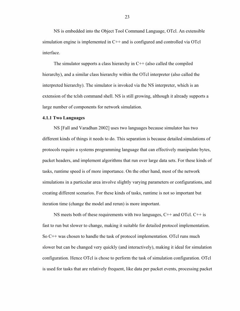
flows. NS (via tclcl) provides glue to make objects and variables appear on both
languages.
C++
OTcl
Figure 4-2. Connection between OTcl and C++
OTcl is used for configuration, setup, and “one-time” stuff. It is also used for
manipulating existing C++ objects. C++ is used to process each packet of a flow and
change behavior of an existing C++ class in ways that weren’t anticipated.
One exception is that most routing is done in OTcl. Ns2 has a special class “class
Tcl” that encapsulates the actual instance of the OTcl interpreter, and provides the
methods to access and communicate with that interpreter. This class provides methods for
the following operation.
• Obtain a reference to the Tcl instance • Invoke OTcl procedures through the interpreter • Retrieve, or pass back results to the interpreter • Report error situations and exit in an uniform manner • Store and lookup “TclObjects” • Acquire direct access to the interpreter.
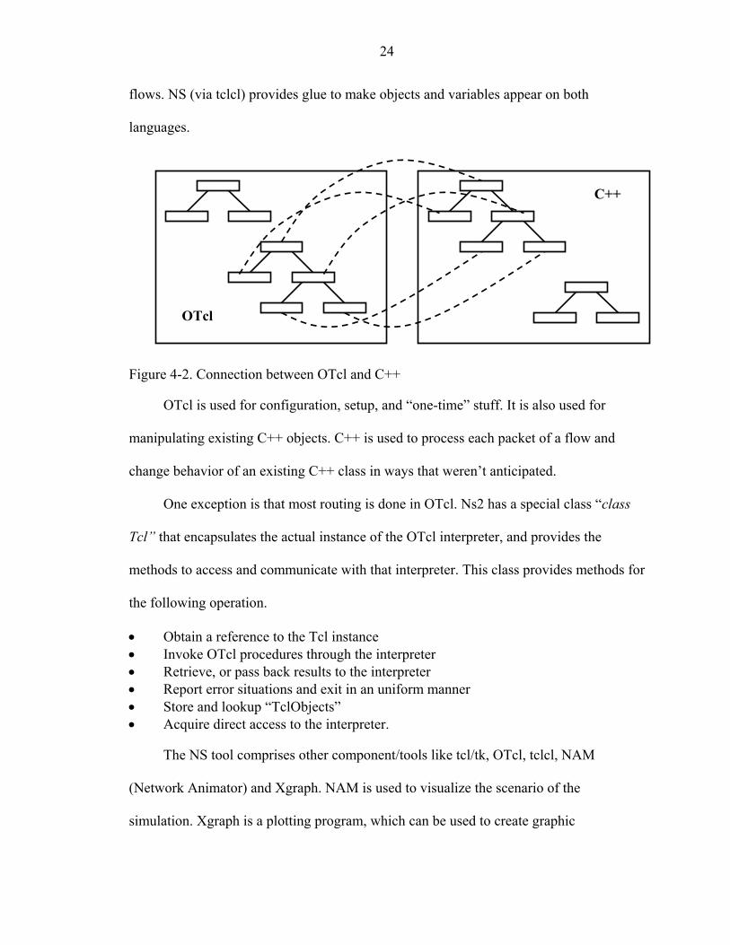
The NS tool comprises other component/tools like tcl/tk, OTcl, tclcl, NAM
(Network Animator) and Xgraph. NAM is used to visualize the scenario of the
simulation. Xgraph is a plotting program, which can be used to create graphic
25
representations of simulation results. Many existing network protocols are supported
inherently by the NS. Their behavior can be studied and analyzed by writing simulation
scripts and running the simulations. Also, the behavior of new protocols can be studied
by implementing them in NS.
Netw
ork C
omponent
otcl
tcl
tclcl
Event Scheduler
ns-2 Figure 4-3. Tcl interpreter
Various network protocols that are currently supported by NS are:
• Application: Network applications such as HTTP, FTP, Telnet, constant bit rate (CBR) traffic generators. Also, web caching is supported.
• Transport Protocols: Extensive support for transport level protocols is provided. Different types of TCP like TCP Tahoe, TCP Reno, TCP NewReno, and TCP with SACK, TCP Vegas, Reno TCP with “Forward Acknowledgment”. Other supported transport protocols include User Datagram Protocol (UDP), Real Time Protocol (RTP) (over UDP), and Scalable Reliable Multicast (SRM).
• Network layer Protocols: Different kinds of routing techniques like unicast routing, multicast routing, hierarchical routing, etc., are supported. Also, mobility protocols like Mobile IP are supported. Also, various adhoc network protocols like DSR, AODV are supported.
• Link/Mac protocols: Local Area Network model is supported in NS along with wireless MAC protocols like 802.11.
Also, different queuing models like Drop Tail, Random Early Detection (RED),
Class Based Queuing (CBQ), Stochastic Fair Queuing (SFQ), and Deficit Round Robin
(DRR) are supported.
26
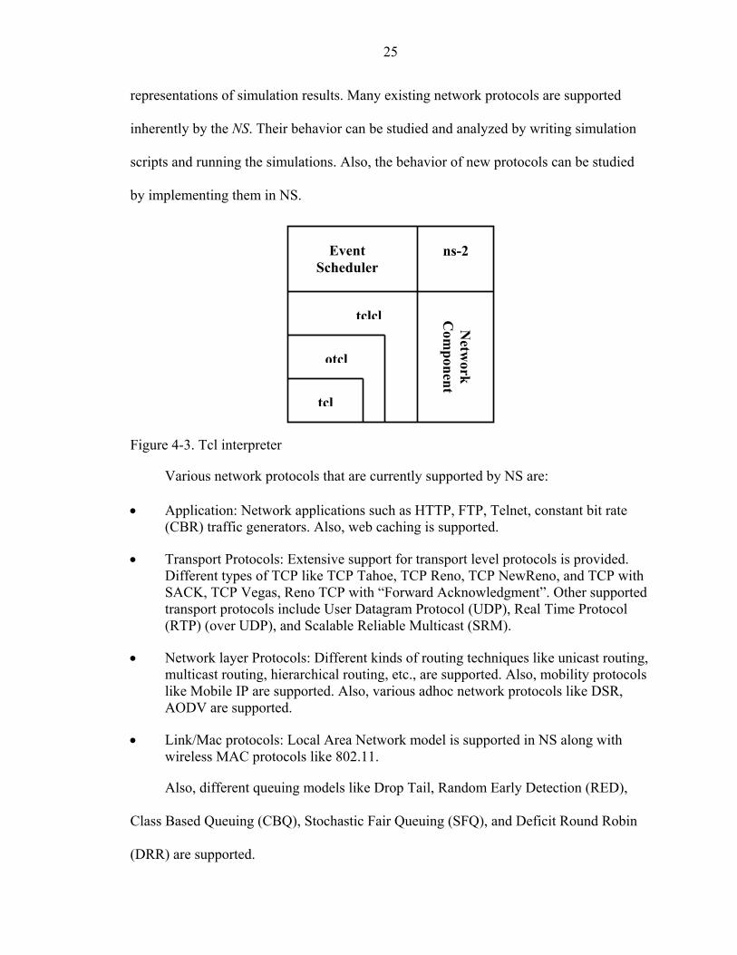
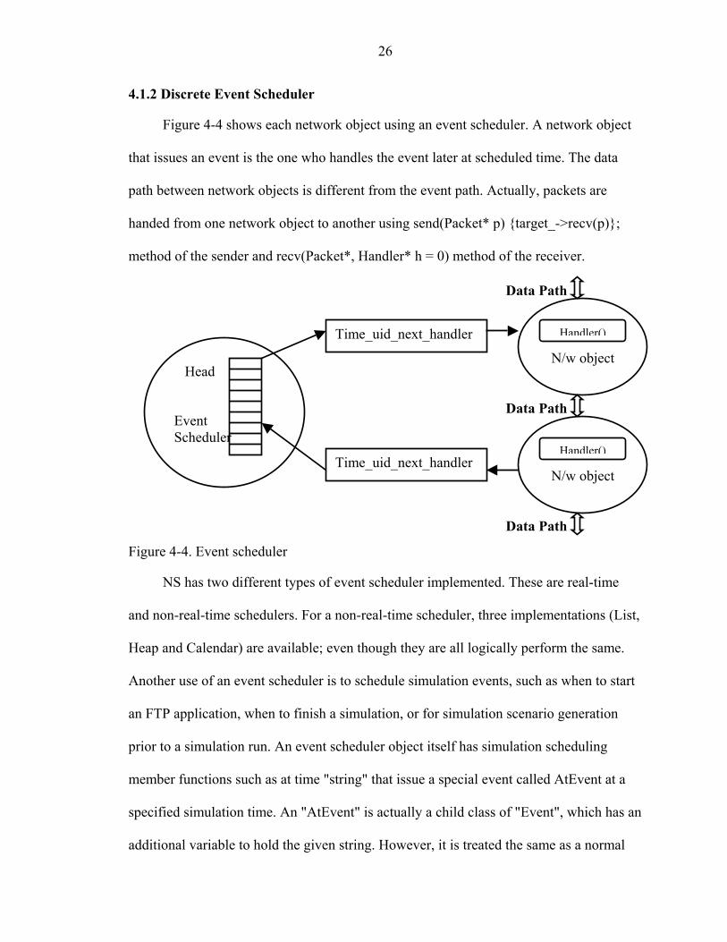
4.1.2 Discrete Event Scheduler
Figure 4-4 shows each network object using an event scheduler. A network object
that issues an event is the one who handles the event later at scheduled time. The data
path between network objects is different from the event path. Actually, packets are
handed from one network object to another using send(Packet* p) {target_->recv(p)};
method of the sender and recv(Packet*, Handler* h = 0) method of the receiver.
Figure 4-4. Event scheduler
Handler()
N/w object Time_uid_next_handler
Time_uid_next_handler
Head Event Scheduler
Handler()
N/w object
Data Path
Data Path
Data Path
NS has two different types of event scheduler implemented. These are real-time
and non-real-time schedulers. For a non-real-time scheduler, three implementations (List,
Heap and Calendar) are available; even though they are all logically perform the same.
Another use of an event scheduler is to schedule simulation events, such as when to start
an FTP application, when to finish a simulation, or for simulation scenario generation
prior to a simulation run. An event scheduler object itself has simulation scheduling
member functions such as at time "string" that issue a special event called AtEvent at a
specified simulation time. An "AtEvent" is actually a child class of "Event", which has an
additional variable to hold the given string. However, it is treated the same as a normal

27
(packet related) event within the event scheduler. When a simulation is started, and as the
scheduled time for an AtEvent in the event queue comes, the AtEvent is passed to an
"AtEvent handler" that is created once and handles all AtEvents, and the OTcl command
specified by the string field of the AtEvent is executed.
4.1.3 Packet Format
A NS packet is composed of a stack of headers, and an optional data space (see
Figure 4-5). As briefly mentioned in the "Simple Simulation Example" section, a packet
header format is initialized when a Simulator object is created, where a stack of all
registered (or possibly useable) headers, such as the common header that is commonly
used by any object as needed, IP header, TCP header, RTP header (UDP uses RTP
header) and trace header, is defined, and the offset of each header in the stack is recorded.
What this means is that whether or not a specific header is used, a stack composed of all
registered headers is created when a packet is allocated by an agent, and a network object
can access any header in the stack of a packet it processes using the corresponding offset
value.
CMR header
Ip header
Tcp header
Rtp header
Trace header
……
Header Data (optional)
Uid_ : unique id Ptype_ : pkt type Size_ : simulated pkt size Ts_ : time stamp
Packet
Figure 4-5. Packet format

28
Usually, a packet only has the header stack (and a data space pointer that is null).
Although a packet can carry actual data (from an application) by allocating a data space,
very few application and agent implementations support this. This is because it is
meaningless to carry data around in a non-real-time simulation.
4.1.4 Node and Routing
A node is a compound object composed of a node entry object and classifiers as
shown in Figure 4-6. There are two types of nodes in NS. A unicast node has an address
classifier that does unicast routing and a port classifier. A multicast node, in addition, has
a classifier that classifies multicast packets from unicast packets and a multicast classifier
that performs multicast routing.
In NS, unicast nodes are the default nodes. To create Multicast nodes the user must
explicitly notify in the input OTcl script, right after creating a scheduler object, that all
the nodes that will be created are multicast nodes. After specifying the node type, the user
can also select a specific routing protocol other than using the default one.
Unicast Node
Node Entry
Port Classifier
Addr Classifier
Application
Agent
Link
Link
Figure 4-6. Node and routing

29
4.2 BlueHoc Simulator
BlueHoc [Kumar 2000] simulator provides an extension of the network simulator
to simulate a Bluetooth scenario. BlueHoc is IBM’s new Bluetooth offering in the open-
source zone. Released under IBM public license it allows users to evaluate how
Bluetooth performs under various ad-hoc networking scenarios. The key issues addressed
by BlueHoc simulator are:
• Device Discovery performance of Bluetooth. • Connection Establishment and QoS negotiation. • Medium access control scheduling schemes. • Radio characteristics of Bluetooth system. • Statistical modeling of the indoor wireless channel. • Performance of TCP/IP based applications over Bluetooth.
BlueHoc provides an accurate simulation of the basic features of Bluetooth
Baseband like frequency hopping, device discovery and channel control.
The following Bluetooth layers have been simulated:
• Bluetooth radio. • Bluetooth Baseband. • Link Manager Protocol. • Logical Link Control and Adaptation Protocol (L2CAP).
BlueHoc is based on the open source simulator network simulator and provides a
Bluetooth extension to NS. BlueHoc uses the TCP/IP simulations of network simulator to
provide a complete simulation model for Bluetooth performance evaluation. It also
provides a simulation platform for testing performance of various routing and service
discovery protocols over ad-hoc networks. Though the simulation model of BlueHoc
closely approximates Bluetooth protocols, it can be used as a platform to evaluate
performance of proposed improvements to the technology.

30
…….
……
……
lm_
sched_
lc_(0) lc_(6)
lq_(0) lq_(6)
tb_(0) tb_(6)
L2CAP
Agent
Agent
Node Entry
Port Classifier
Addr Classifier
Application
Agent
BTHost
default target
ipaddr
Figure 4-7. BlueHoc node structure
The BlueHoc simulation program implements basic features of Bluetooth
Baseband, Logical Link Control and Adaptation Protocol (L2CAP) and Link Manager
Protocol (LMP). Figure 4-7 shows the node structure of a BlueHoc node. The entry point
hands over packet to address classifier. Address classifier checks the address and hands
over the packet to either BTHost or to the port demultiplexer depending upon whether the

31
address matches its own address or not. The default target is assumed to be BTHost as
there is no concept of access point in this simulator.
4.2.1 Device Discovery and Paging
BlueHoc simulates the processes of inquiry and paging almost exactly as specified
in Bluetooth Specification. Simulation starts with the creation of a master node and
several slave nodes. The master node starts inquiry procedure. The BTHost at the master
sends an HCI_Inquiry command to the Baseband. Though HCI commands are actually
packets, which are transported over a physical bus, they have been simulated as function
calls. The parameters to the HCI_inquiry command are the number of responses required
and inquiry timeout. These can be entered using the graphical interface. In response to the
HCI_Inquiry command, the Baseband starts sending Inquiry packets with the general
access code. The transmission frequency depends upon the clock of the master and the
general inquiry access code. The slaves respond to this inquiry with FHS packets, which
contain the device address and the clock of the slave. When required numbers of inquiry
responses are obtained (or if inquiry timeout occurs), the master starts paging.
4.2.2 Connection Establishment in BlueHoc
Some connection establishment related to signaling has been simulated in BlueHoc.
4.2.2.1 LMP signaling
Once paging is over and the slave is tuned to the master hopping sequence, Link
Manager Protocol establishes an Asynchronous Connection-Less (ACL) link between the
master and the slave. For this the master's LMP sends an LMP_host_connection_req to
the peer LMP. When the master's LMP receives a response from the slave LMP it send an
HCI Event to BTHost indicating that the connection with the required device has (or has
not) been created. The master then sends a QoS setup command with the QoS parameters,
32
which depend on the application for which the connection is required. For simplicity it is
assumed that there is only one flow per ACL connection. The LMP passes on the QoS
parameters to the deficit round robin-based scheduler which finds out whether the
connection can be accepted or not.
4.2.2.2 L2CAP connection establishment
After the QoS negotiation at the LMP is over, it sends
HCI_QoS_setup_complete_event to BTHost. The host then sends L2CA_Connect_Req
to L2CAP. Signaling takes place between L2CAP peers. Each L2CAP channel has a
connection identifier (CID) associated with it. For signaling the CID is 1. The L2CAP
side, which initiates connection establishment, sends an L2CAP_connection_request and
the other sides send an L2CAP_connection_response. Through this exchange each end
can identify the other end through its CID. Several L2CAP connections can be
established in this manner over a single ACL connection. However in this version of the
simulator multiple L2CAP connections over a single ACL connection are not considered
since QoS negotiation is done only once for per ACL connection at LMP level instead of
L2CAP. The L2CAP level QoS negotiation not implemented.
4.2.2.3 QoS mapping
QoS mapping and negotiations are done only once per ACL connection. The QoS
requirements for standard applications (like Telnet, FTP, packetized voice) are conveyed
to the MAC (scheduler) using Flow Specifications similar to RFC 1363. The Deficit
Round Robin scheduler first finds the appropriate Baseband packet type to be used
depending upon loss sensitivity and application level MTU. It decides whether a
connection can be admitted depending upon current traffic level and the requirements of
the connection. If admitted, the connection gets a 'quanta' of service per round robin
33
cycle. Reservations are made only in the forward (master to slave) direction. Though no
reservation is made for the reverse side, a flow is considered backlogged if either the
forward or reverse side of the ACL link is backlogged. The mapping used is very
application specific. The graphical interface allows the user to specify the application to
be FTP, Telnet or voice.
4.2.3 Logical Link Control and Adaptation Protocol Simulation
Apart from sending and receiving L2CAP_connection_req and
L2CAP_connection_response, and conveying remote CIDs, the simulated L2CAP has
two main functionalities
• Performs segmentation and reassembly (SAR) for higher layer packets.
• Implements DATA_WRITE primitive for transfer of higher layer packets over a logical link identified by a CID.
4.3 LAPSim Simulator
The goal of LAPSim [Lee and Helal 2001] is to investigate the end-to-end impact
on IP applications requiring communication between a mobile Bluetooth node and an
Internet node through a Bluetooth LAP gateway. Application behavior in connection with
Bluetooth local connectivity is explored. LAPSim simulates Bluetooth LAN Access
Profile. It supports Bluetooth upper layers (PPP, RFCOMM, and L2CAP layer) as well as
the macro-simulation of the HCI interface. L2CAP layer supports connection-oriented
channels. Lower layers such as LMP and Baseband are not simulated in this Simulator.
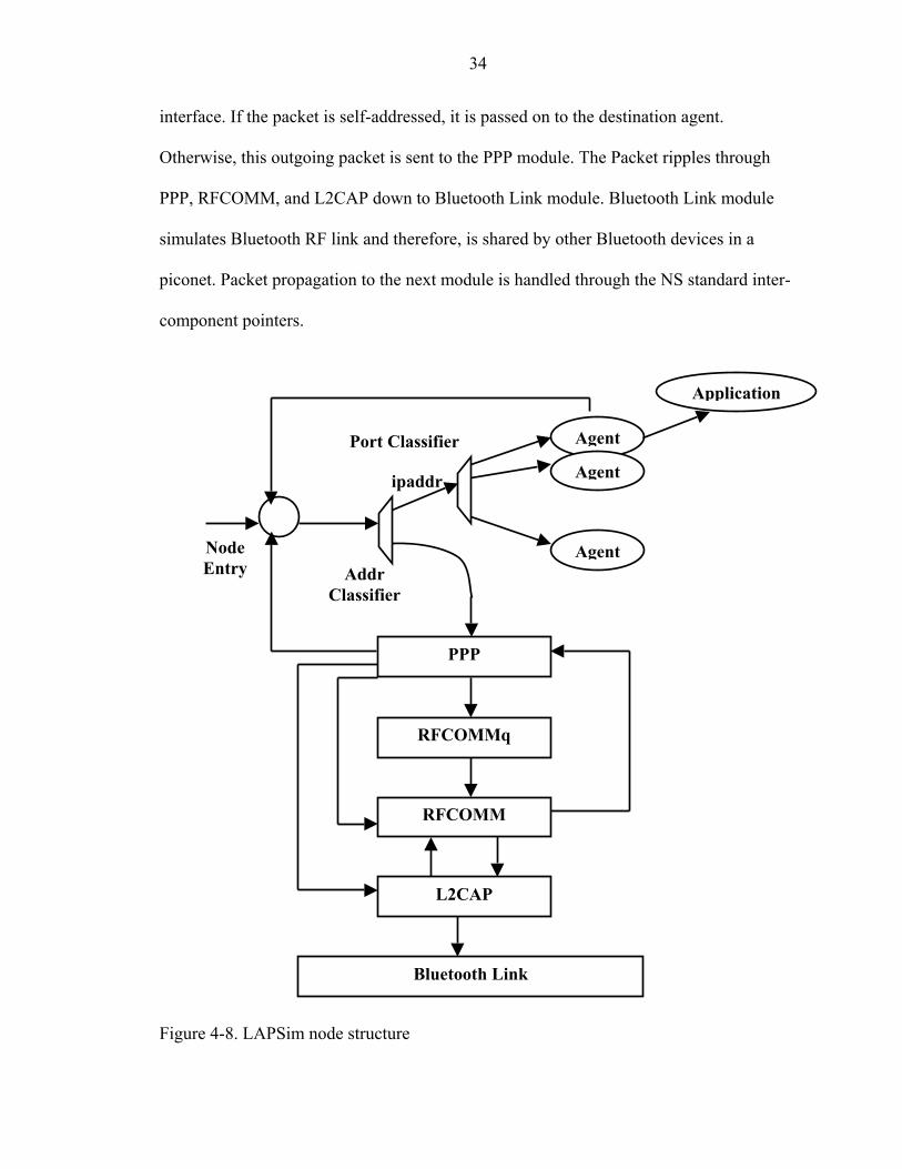
Figure 4-8 shows the architecture of a LAPSim node. A packet sent by an agent
such as application or FTP agent is handed to the address demultiplexer (addr demux)
through the node’s entry point (entry_). Depending on the destination address of IP
header, the packet is forwarded either to port demultiplexer or to the Bluetooth network
34
interface. If the packet is self-addressed, it is passed on to the destination agent.
Otherwise, this outgoing packet is sent to the PPP module. The Packet ripples through
PPP, RFCOMM, and L2CAP down to Bluetooth Link module. Bluetooth Link module
simulates Bluetooth RF link and therefore, is shared by other Bluetooth devices in a
piconet. Packet propagation to the next module is handled through the NS standard inter-
component pointers.
Bluetooth Link
L2CAP
RFCOMM
RFCOMMq
Agent
Agent
Node Entry
Port Classifier
Addr Classifier
Application
Agent
PPP
ipaddr
Figure 4-8. LAPSim node structure
35
In the case of incoming packets, the reverse path is taken. A packet sent by other
devices arrives at L2CAP through address demux associated with the Bluetooth Link. It
is routed to the PPP module. From there, the packet is handed over to the node’s entry
point.
Bluetooth Link implements several important features of the Baseband layer. These
include bandwidth, delay, ACL packet types, error model, retransmission and
Segmentation and Reassembly at L2CAP.
The motivation and goal of this work is to be able to study future proximity-based
and pervasive computing applications in a Bluetooth local connectivity environment.

CHAPTER 5 BLUESIM
Having concluded that there is a need for a complete Simulator to simulate LAN
Access Profile, observing the available simulators, and their drawbacks we in this thesis
attempt to develop a simulator, which simulates a LAN Access Profile. We approach our
goal of developing a simulator by taking the BlueHoc Simulator, adding the
functionalities of PPP and RFCOMM connection establishment, data transfer over PPP
and RFCOMM, and extending the functionality of Master of the piconet to a LAN
Access Point.
As described earlier BlueHoc has the ability to form piconet. But it does not have
the ability to
• Simulate RFCOMM and PPP connection establishment. • Simulate data transfer over PPP and RFCOMM. • Simulate an Access point.
Also LAPSim does not simulate
• Lower layers • Piconet formation.
Simulation of the above listed tasks is necessary for any simulator to simulate a
LAN Access Profile. We attempt to simulate all the above said tasks in this thesis by
developing a simulator, BlueSim. In this chapter we describe the implementation details
of BlueSim, compare its architecture with available simulators, and demonstrate
experimentation results of the tests that were done with this simulator.
36
37
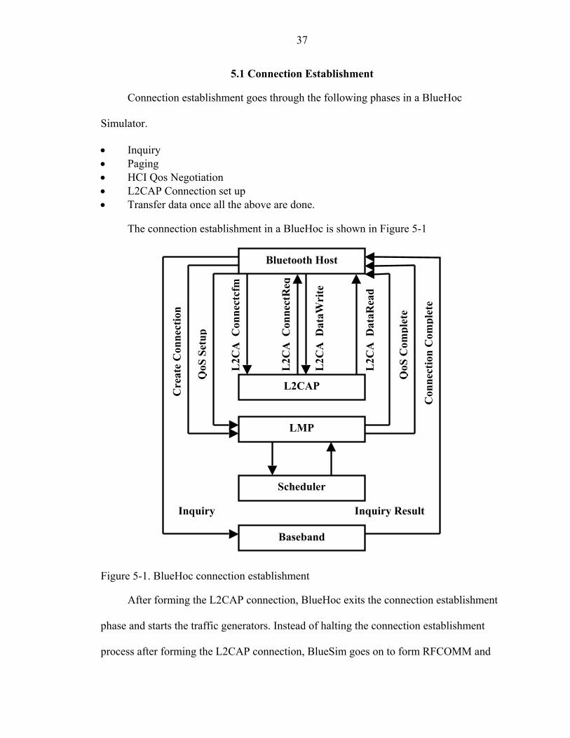
5.1 Connection Establishment
Connection establishment goes through the following phases in a BlueHoc
Simulator.
• Inquiry • Paging • HCI Qos Negotiation • L2CAP Connection set up • Transfer data once all the above are done.
The connection establishment in a BlueHoc is shown in Figure 5-1
Inquiry
Baseband
Scheduler
LMP
L2CAP
Bluetooth Host
Inquiry Result
Cre
ate
Con
nect
ion
Con
nect
ion
Com
plet
e
QoS
Set
up
QoS
Com
plet
e
L2C
AC
onne
ctcf
m
L2C
AC
onne
ctR
eq
L2C
AD
ataR
ead
L2C
AD
ataW
rite
Figure 5-1. BlueHoc connection establishment
After forming the L2CAP connection, BlueHoc exits the connection establishment
phase and starts the traffic generators. Instead of halting the connection establishment
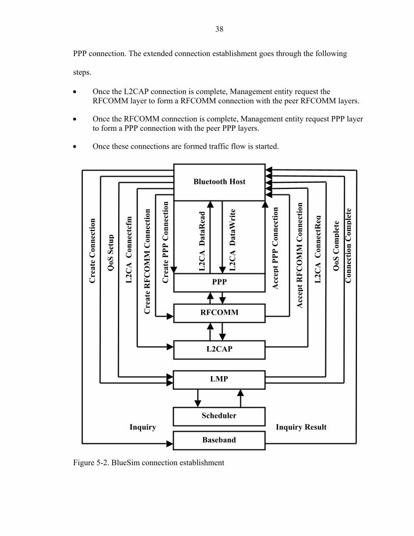
process after forming the L2CAP connection, BlueSim goes on to form RFCOMM and
38
PPP connection. The extended connection establishment goes through the following
steps.
• Once the L2CAP connection is complete, Management entity request the RFCOMM layer to form a RFCOMM connection with the peer RFCOMM layers.
• Once the RFCOMM connection is complete, Management entity request PPP layer to form a PPP connection with the peer PPP layers.
• Once these connections are formed traffic flow is started.
Acc
ept R
FCO
MM
Con
nect
ion
Acc
ept P
PP C
onne
ctio
n
Cre
ate
PPP
Con
nect
ion
Cre
ate
RFC
OM
M C
onne
ctio
n
QoS
Set
up
Cre
ate
Con
nect
ion
L2C
AC
onne
ctcf
m
L2C
AD
ataW
rite
L2C
AD
ataR
ead
L2C
AC
onne
ctR
eq
QoS
Com
plet
e C
onne
ctio
n C
ompl
ete
Inquiry Result
Bluetooth Host
L2CAP
LMP
Scheduler
Baseband Inquiry
RFCOMM
PPP
Figure 5-2. BlueSim connection establishment
39
5.2 Modifications to Bluetooth Host
Bluetooth Host module is the management entity, which controls the Connection
establishment in BlueHoc. We extend the functionality of Bluetooth Host by adding extra
functions for initiation and establishment of PPP and RFCOMM connections.
In BlueHoc, once the L2CAP connection is formed, the L2CAP layer sends an
L2CAP connection complete signal to Bluetooth Host. Bluetooth Host upon receiving the
connection complete event from L2CAP starts the Traffic generators. These generate the
traffic to slaves depending on the application, which were configured for that slave.
BlueSim differs from BlueHoc here. Instead of starting traffic generators, BlueSim
instructs the RFCOMM layer to form connections with the peer RFCOMM layers of the
Slaves. It then waits till it receives a reply from RFCOMM layer that connection was
formed. Once it receives a RFCOMM connection established Signal from RFCOMM
layer, Bluetooth Host Instructs the PPP layer to establish PPP link with its peer PPP layer
of the slave. After the PPP layer forms the connection with its peer, it informs the
Bluetooth Host that the connection has been formed. Now Bluetooth Host starts the
traffic generator. Instead of passing traffic directly to L2CAP, as in BlueHoc, Bluetooth
Host sends traffic to PPP layer. PPP layer then adds its header to the packet and forwards
it to RFCOMM layer, which adds its header and forwards the packet to L2CAP layer.
The same, but in opposite direction is done on the receiving side.
5.3 Modifications to L2CAP
L2CAP layer is the layer where protocol multiplexing and segmentation and
reassembly of packets from various upper layer protocols are done. BlueSim extends the
functionality of L2CAP implementation of BlueHoc by adding the functionality to

40
Handle RFCOMM packets. L2CAP checks the psm value of each packet and sends the
packets with a psm value of 0x03 to RFCOMM.
5.4 RFCOMM Layer
BlueSim adds the functionality of the RFCOMM layer to BlueHoc. We try to
simulate the connection establishment process of RFCOMM.
Figure 5-3 shows the simulated RFCOMM connection establishment process.
User Data on UIH Frames
UA Frame
SABM Frame
UA FRAME (DLCI=0)
SABM FRAME (DLCI=0)
Set up L2CAP Connection
Res
pond
ing
RFC
OM
M
Initi
alin
g R
FCO
MM
Figure 5-3. RFCOMM connection establishment
As shown in the figure the connection establishment process starts after the L2CAP
connection is formed. The initiating device, which is master, first sends a Set
Asynchronous Balanced Mode (SABM) frame with (Data Link Connection Identifier
(DLCI) value set to 0x00. The value of 0x00 is used for control connections. The
responding device might either accept or reject the connection. If the responding device
does not want to connect, it sends a Disconnect Mode (DM) frame. If the responding

41
device accepts a connection it sends Unnumbered Acknowledgement (UA) with same
DLCI value, i.e. 0x00. Upon receiving an UA frame with DLCI value of 0x00, the
initiating device open a new connection for data transfer. It sends a SABM frame with a
non-zero DLCI value. The responding device also responds with a UA frame containing
non-zero DLCI. Now the connection is complete and ready for Data transfer. All the
packets from above layer are considered to be data packets and hence sent as
Unnumbered Information with Header Check (UIH) frames.
5.5 PPP Layer
In this section we explain the PPP connection establishment process. Figure 5-4
shows the PPP connection establishment process. For PPP connection establishment,
RFCOMM connection is pre-requisite. User data will be allowed only after PPP
connection is set up.
Confirm Acknowledge
Confirm Acknowledge
User Data
Send Acknowledge
Send Acknowledge
Connection Request
Connection Request
Set up RFCOMM ConnectionR
espo
ndin
g PP
P
Initi
alin
g PP
P
Figure 5-4. PPP connection establishment
42
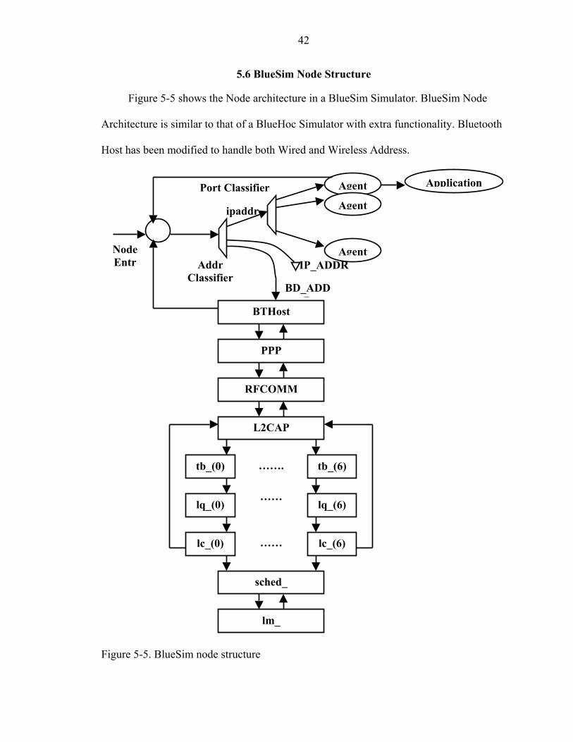
5.6 BlueSim Node Structure
Figure 5-5 shows the Node architecture in a BlueSim Simulator. BlueSim Node
Architecture is similar to that of a BlueHoc Simulator with extra functionality. Bluetooth
Host has been modified to handle both Wired and Wireless Address.
IP_ADDR
BD_ADDR
ipaddr
BTHost
Agent
Addr Classifier
Port ClassifierAgent
Agent
PPP
RFCOMM
L2CAP
tb_(6)tb_(0)
lq_(6)lq_(0)
lc_(6)lc_(0)
sched_
…….
……
……
lm_
Node Entr
Application Figure 5-5. BlueSim node structure
43
The Address Classifier in a Bluetooth Host is extended to handle both wired and
wireless nodes. Addresses from 0-8 are considered to be Bluetooth Device address and
the rest of the addresses are Wired Node address. The entry point hands over the arriving
packet to the Address Classifier. The Address Classifier checks for the address and passes
on to either itself or to Wired Node or to BTHost. If a packet is self addressed then that
packet is passed on to its relevant Agent. If the packet is destined to a Wired node then
the classifier checks the slot number of the destination and passes on to respective
Handler in that slot. If the packet is destined for a Bluetooth enabled device then it is sent
to BTHost.
5.7 Routing
As of now manual routing is used to send packets from a wired node to Bluetooth
enabled devices. All the routes are configured manually using “add-route-to-adj-node”
command. If two nodes, n1 and n2 are connected then the route should be configured as
• [$n0 get-module “Manual”] add-route-to-adj-node –default $n1
• [$n1 get-module “Manual”] add-route-to-adj-node –default $n0
At the same time we have to add an entry to the Classifier table of LAN Access
Point if there are any Wired Nodes connected to it directly. This is for letting the
Classifier at LAN Access Point to know where it has to forward packets if there is any
destined to Wired node and reached LAN Access Point.
5.8 Experiments Conducted
We conducted a series of experiments to validate the performance of BlueSim in
various scenarios. These include all the functionality requirements of a LAN Access
Profile as described in specification.
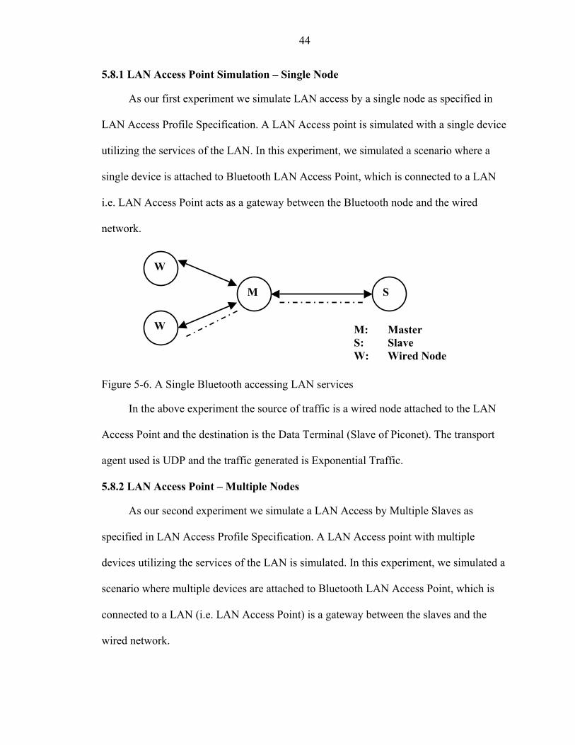
44
5.8.1 LAN Access Point Simulation – Single Node
As our first experiment we simulate LAN access by a single node as specified in
LAN Access Profile Specification. A LAN Access point is simulated with a single device
utilizing the services of the LAN. In this experiment, we simulated a scenario where a
single device is attached to Bluetooth LAN Access Point, which is connected to a LAN
i.e. LAN Access Point acts as a gateway between the Bluetooth node and the wired
network.
M S
W
M: Master S: Slave W: Wired Node
W
Figure 5-6. A Single Bluetooth accessing LAN services
In the above experiment the source of traffic is a wired node attached to the LAN
Access Point and the destination is the Data Terminal (Slave of Piconet). The transport
agent used is UDP and the traffic generated is Exponential Traffic.
5.8.2 LAN Access Point – Multiple Nodes
As our second experiment we simulate a LAN Access by Multiple Slaves as
specified in LAN Access Profile Specification. A LAN Access point with multiple
devices utilizing the services of the LAN is simulated. In this experiment, we simulated a
scenario where multiple devices are attached to Bluetooth LAN Access Point, which is
connected to a LAN (i.e. LAN Access Point) is a gateway between the slaves and the
wired network.
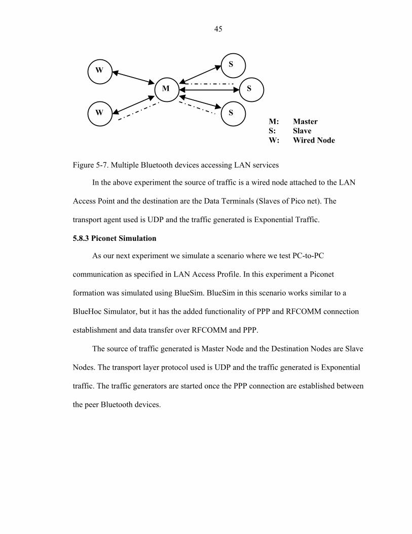
45
M
S W
S
S M: Master S: Slave W: Wired Node
W
Figure 5-7. Multiple Bluetooth devices accessing LAN services
In the above experiment the source of traffic is a wired node attached to the LAN
Access Point and the destination are the Data Terminals (Slaves of Pico net). The
transport agent used is UDP and the traffic generated is Exponential Traffic.
5.8.3 Piconet Simulation
As our next experiment we simulate a scenario where we test PC-to-PC
communication as specified in LAN Access Profile. In this experiment a Piconet
formation was simulated using BlueSim. BlueSim in this scenario works similar to a
BlueHoc Simulator, but it has the added functionality of PPP and RFCOMM connection
establishment and data transfer over RFCOMM and PPP.
The source of traffic generated is Master Node and the Destination Nodes are Slave
Nodes. The transport layer protocol used is UDP and the traffic generated is Exponential
traffic. The traffic generators are started once the PPP connection are established between
the peer Bluetooth devices.

46
S
S
S
M: Master S: Slave Control Data
M
Figure 5-8. BlueSim piconet simulation
5.8.4 LAN Access Point as an Intermediate Node
As a last experiment we test the functionality of the LAN Access Point. This
experiment is done to validate the functionality of Master of Piconet as a LAN Access
Point. A scenario in which LAN Access point functions as an intermediate node between
the wired nodes is simulated. In this simulation the LAN Access Point functions just as
any other wired node, forwarding packets to appropriate destinations.
S
S
M: Master S: Slave W: Wired Node
W
W S
M
Figure 5-9. LAN Access Point as an intermediate node
In this experiment the source and Destination of traffic are wired nodes attached to
the LAN Access Point. The transport agent used is UDP and the traffic generated is
Exponential Traffic.
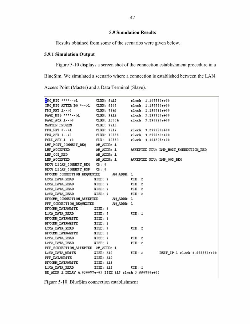
47
5.9 Simulation Results
Results obtained from some of the scenarios were given below.
5.9.1 Simulation Output
Figure 5-10 displays a screen shot of the connection establishment procedure in a
BlueSim. We simulated a scenario where a connection is established between the LAN
Access Point (Master) and a Data Terminal (Slave).
Figure 5-10. BlueSim connection establishment
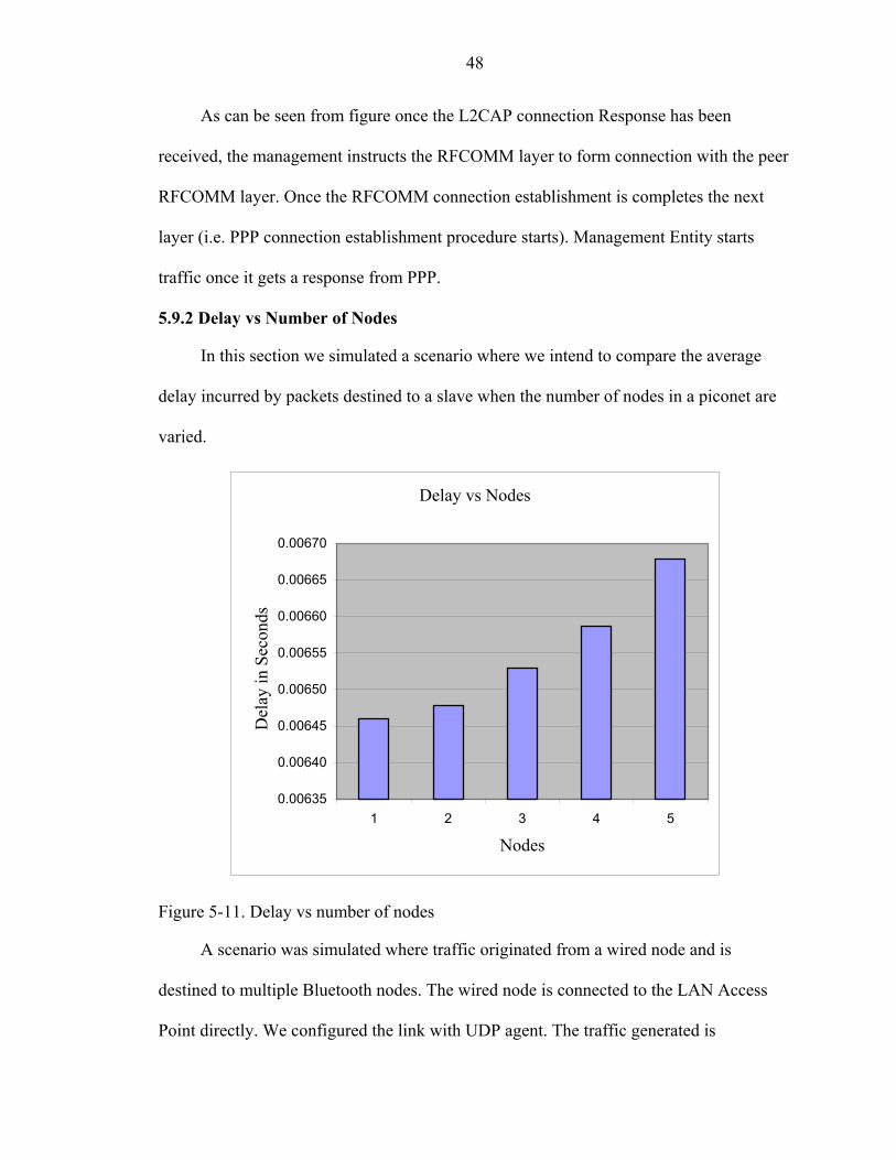
48
As can be seen from figure once the L2CAP connection Response has been
received, the management instructs the RFCOMM layer to form connection with the peer
RFCOMM layer. Once the RFCOMM connection establishment is completes the next
layer (i.e. PPP connection establishment procedure starts). Management Entity starts
traffic once it gets a response from PPP.
5.9.2 Delay vs Number of Nodes
In this section we simulated a scenario where we intend to compare the average
delay incurred by packets destined to a slave when the number of nodes in a piconet are
varied.
Delay vs Nodes
0.00635
0.00640
0.00645
0.00650
0.00655
0.00660
0.00665
0.00670
1 2 3 4 5
Nodes
Del
ay in
Sec
onds
Figure 5-11. Delay vs number of nodes
A scenario was simulated where traffic originated from a wired node and is
destined to multiple Bluetooth nodes. The wired node is connected to the LAN Access
Point directly. We configured the link with UDP agent. The traffic generated is
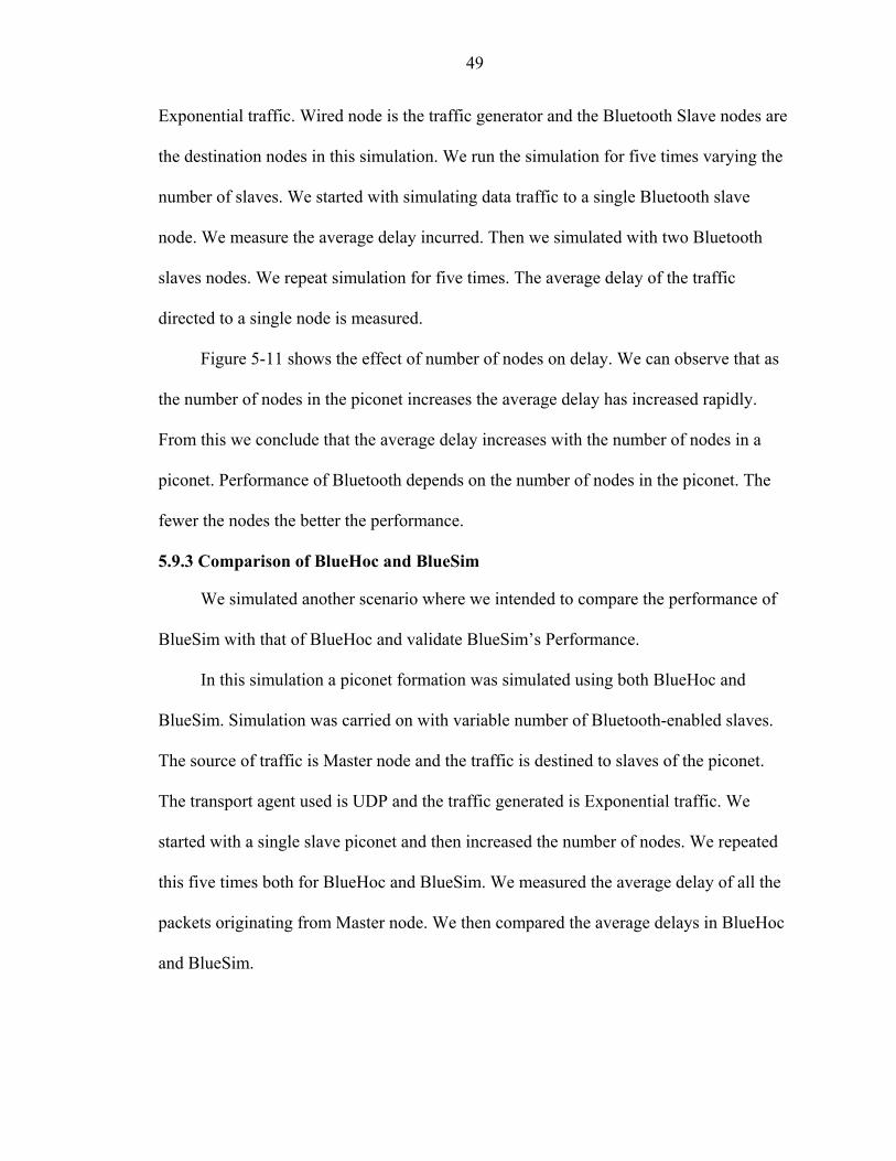
49
Exponential traffic. Wired node is the traffic generator and the Bluetooth Slave nodes are
the destination nodes in this simulation. We run the simulation for five times varying the
number of slaves. We started with simulating data traffic to a single Bluetooth slave
node. We measure the average delay incurred. Then we simulated with two Bluetooth
slaves nodes. We repeat simulation for five times. The average delay of the traffic
directed to a single node is measured.
Figure 5-11 shows the effect of number of nodes on delay. We can observe that as
the number of nodes in the piconet increases the average delay has increased rapidly.
From this we conclude that the average delay increases with the number of nodes in a
piconet. Performance of Bluetooth depends on the number of nodes in the piconet. The
fewer the nodes the better the performance.
5.9.3 Comparison of BlueHoc and BlueSim
We simulated another scenario where we intended to compare the performance of
BlueSim with that of BlueHoc and validate BlueSim’s Performance.
In this simulation a piconet formation was simulated using both BlueHoc and
BlueSim. Simulation was carried on with variable number of Bluetooth-enabled slaves.
The source of traffic is Master node and the traffic is destined to slaves of the piconet.
The transport agent used is UDP and the traffic generated is Exponential traffic. We
started with a single slave piconet and then increased the number of nodes. We repeated
this five times both for BlueHoc and BlueSim. We measured the average delay of all the
packets originating from Master node. We then compared the average delays in BlueHoc
and BlueSim.

50
Bluehoc Vs BlueSim
0.00300
0.00320
0.00340
0.00360
0.00380
0.00400
0.00420
0.00440
0.00460
1 2 3 4 5
Number of Nodes
Ave
rage
Del
ay in
Sec
onds
Bluehoc BlueSim
Figure 5-12. BlueHoc vs BlueSim
Figure 5-12 compares average delay in both the BlueHoc and BlueSim. We can see
that the delay has been increased consistently. We attribute this additional delay for extra
layers we added, PPP and RFCOMM. PPP and RFCOMM encapsulation consumes the
extra time by which BlueHoc and BlueSim vary.
5.9.4 Delay Distribution
We simulated another scenario where we simulate Bluetooth Slaves accessing LAN
services and the delay for each packet is calculated. A scenario where a LAN Access
Point forwards packets to all the slaves is simulated. A piconet consisting of 7 slaves, the
maximum a piconet can accommodate and are connected to a LAN Access Point is
simulated. The source of the traffic is a wired node and the packets are destined to all the
nodes. The transport agent used is UDP and the traffic generated is Exponential traffic.
51
Delay Distribution
0.0000
0.0020
0.0040
0.0060
0.0080
0.0100
0.0120
0.0140
0.0160
0.0180
0.0200
0 1 2 3 4 5 6 7 8
Node Number
Del
ay in
Sed
onds
Figure 5-13. Delay distribution
Delay for each packet is calculated. The delay calculated is the delay between the
LAN Access Point and the destination slaves. Figure 5-13 shows the delay distribution
for all the slaves.

CHAPTER 6 CONCLUSION AND FUTURE WORK
6.1 Conclusion
In this thesis, we have studied some of the available Bluetooth simulators and
developed a Bluetooth LAN Access Profile Simulator to simulate Bluetooth’s
performance in various mobile commerce scenarios. This new simulator can be used to
simulate various scenarios more realistically when compared with the existing simulators.
Table 6-1 summarizies features of the available simulators with our simulator.
Table 6-1 A comparative table of available simulators BlueHoc LAPSim BlueSim Baseband YES No Yes Link controller Yes No Yes LMP Yes No Yes L2CAP Yes Yes Yes RFCOMM No Yes Yes PPP No Yes Yes Piconets Yes No Yes LAN access point No Yes Yes Bi-directional Traffic No Yes No
6.2 Future Work
Our Simulator is based on network simulator. Its performance and results depend
on the performance of the network simulator. Also, more number of experiments needs to
be conducted.
Though we tried to simulate the LAN Access Profile to the fullest, the simulator
developed does not simulate the LAN Access Profile completely. There are some missing
features, which are needed, to make the developed simulator complete.
52

53
Some of the features missing are
• Wired node creation is not automated. • Bi-directional Traffic is not implemented • Master-Slave role reversal is not simulated • Service Discovery is not simulated
Simulator will be a complete simulator once the above listed features are
incorporated into BlueSim.
6.3 Suggested Modifications
In this section, the possible modifications needed to achieve the above listed four
features are described.
6.3.1 Automate Wired Network Creation
As BlueSim simulates a LAN Access Profile, we have a network of wired nodes.
Since BlueSim uses manual routing, routing information is added manually for each
simulation scenario. As the number of nodes increases the manual routing will become a
very difficult task. So there is a need for adding a mechanism to automate the process of
Wired Network creation. This can be accomplished in two ways. One method is to
modify the LAN Access Point so that it accepts connections from Wired nodes. Doing so
will give the users flexibility to configure networks as they prefer. The other way of
doing it involves creating a graphical interface, which accepts the topology and
configures the network automatically from topology.
6.3.2 Bi-directional Traffic
Since BlueSim extends the functionality of BlueHoc by adding some of the layers,
it has the same feature missing as in BlueHoc. The applications send traffic in only one
direction i.e. from Master to Slave. This is because, L2CAP channels have been
established only in the forward (master to slave) direction and not in the reverse. TCP
54
acknowledgements are the only data (for L2CAP) in the reverse direction so it is being
piggybacked with the Baseband acknowledgements.
The steps for configuring and starting applications with QoS requirements for the
reverse direction are
• L2CAP channel establishment in the reverse direction • Mapping the QoS of the reverse channel to a MAC level parameter. • Attaching applications to slaves.
So, setting up an application for the reverse link is exactly the same as for the
forward link except that the MAC scheduling might be changed to incorporate QoS for
reverse direction.
6.3.3 Master-Slave Switching Roles
In a general Mobile Commerce scenario, it is the roaming Bluetooth enabled
device, which starts inquiring for the LAN Access Points. So it takes the role of the
Master. But since there are lots of nodes using the services of the LAN Access Point,
these devices switch roles once the inquiry process is complete.
The mechanism essentially involves the slave sending its FHS packet to the Master;
the Master takes on a CLK offset to match the Slave’s CLKN, while the Slave switches
to using its own CLKN, and each device swaps access codes. The new Master also sends
an LMP message, which contains the lower part of the Bluetooth CLK not contained in
the FHS together with the sub-slot offset information in micro seconds to allow the new
Slave to fully synchronize its timing.
Addition of this functionality will enhance the simulator features and will simulate
the scenarios more closely to the specification.
55
6.3.4 Service Discovery
The service discovery protocol (SDP) allows applications to discover the services
provided by server applications and to determine the characteristics of those available
services. The attributes of a service include the type or class of the service offered and the
mechanism or the protocol needed to use the service.
When Service discovery is simulated the slaves will have a choice to choose from
the available Bluetooth LAN Access Points. Simulation of SDP will make the simulator a
complete simulator.
LIST OF REFERENCES
Bray J. and Sturman C. 2000. Connect without cables. Prentice Hall Professional, Upper Saddle River, NJ.
Chung J. and Claypool M. 1999. NS by Example. Worcester Polytechnic Institute,
Worcester, MA. Available at http://nile.wpi.edu/NS/. Accessed on 07/20/2002. Fall K. and Varadhan K. 2002. The ns Manual. University of Southern California-
Information Science Institute, Los Angeles, CA. Available at http://www.isi.edu/nsnam/ns/doc/ns_doc.pdf. Accessed on 06/18/2002.
Greis M. 2002. Tutorial for the network simulator. University of Southern California-
Information Science Institute, Los Angeles, CA. Available at http://www.isi.edu/nsnam/ns/tutorial/index.html. Accessed on 04/16/2002.
Kumar A. 2000. BlueHoc Manual. IBM Corporation-India Research Lab, New Delhi,
India. Available at http://www-124.ibm.com/developerworks/opensource/bluehoc/tutorial/docpage.html. Accessed on 08/15/2002.
Kumar A. 2001, BlueHoc Tutorial. IBM Corporation-India Research Lab, New Delhi,
India. Available at http://www-124.ibm.com/developerworks/opensource/bluehoc/pres/pres3/bt-pres_files/frame.htm. Accessed on 08/15/2002.
Lee C. and Helal A. 2001. An ns-based Bluetooth LAP simulator. Proceedings of the
26th Annual IEEE Conference on Local Computer Networks (LCN), IEEE Press, Tampa, FL, pp. 525 – 532.
Lyytinen K. 2001. M-commerce – mobile commerce: A new frontier for e-business.
Proceedings of the 34th Annual Hawaii International Conference on System Sciences, IEEE Press, Maui, HI, pp. 3509 – 3509.
Mahadev S. 2001. Pervasive computing: Vision and challenges. IEEE Personal
Communications, 8(4): 10 – 17. Miller B. and Bisdikian C. 2000. Bluetooth revealed: The insider's guide to an open
specification for global wireless communications. Prentice Hall Professional, Upper Saddle River, NJ.
56
57
Muller N. 2000. Bluetooth Demystified. McGraw-Hill Professional, Two Penn Plaza,
NY. Samaras G. 2002. Mobile commerce: Vision and challenges (location and its
management). Proceedings of IEEE Applications and the Internet, IEEE Press, Nara, Japan, pp. 43-44.
Senn J. 2000. The emergence of m-commerce. IEEE Journal Computer, 33(12): 148 -
150. Varshney U. and Vetter R. 2001. A framework for the emerging mobile commerce
applications. Proceedings of the 34th Annual Hawaii International Conference on System Sciences, IEEE Press, Maui, HI, pp. 3516-3525.
Varshney U., Vetter R. and Kalakota R. 2000. Mobile commerce: A new frontier. IEEE
Journal Computer, 33(10): 32 – 38.
BIOGRAPHICAL SKETCH
Sasidhar Parvatham was born on April 16th, 1978, in Guntur, India. He received
his bachelor’s degree in computer science and engineering from Osmania University,
Hyderabad, India, in 2000.
He joined the University of Florida in 2000 to pursue a master’s degree in
computer and information science and engineering. He worked as a Research assistant
under the guidance of Dr. Jose Principe during his stay at the University of Florida.
He worked as a Software Engineer Intern in the Voice Technology Group of Cisco
Systems, San Jose, in the summer of 2001.
58