Embed Size (px)
Citation preview

1 Blue Sky Plan®
Blue Sky Plan®
USER MANUAL
**Manual Revision 01**

2 Blue Sky Plan®
Contents
1 Introduction .............................................................................................................. 4
2 Installing Blue Sky Plan ............................................................................................ 6
2.1 Installation process (Windows)........................................................................... 6
2.2 Installation process (Mac OS X) ......................................................................... 8
2.3 Hardware requirements .................................................................................... 10
2.4 Operating system ............................................................................................. 10
3 Loading the patient’s CT or CBCT scan into Blue Sky Plan ................................... 11
3.1 Selecting the DICOM images location .............................................................. 11
3.2 Selecting the series .......................................................................................... 12
3.3 Enhancing performance ................................................................................... 12
3.4 Scan alignment and defining the range of slices .............................................. 12
3.5 Positioning the panoramic curve ...................................................................... 14
4 Software interface .................................................................................................. 15
4.1 Screens and views ........................................................................................... 16
4.2 Multi-planer screen ........................................................................................... 26
5 Placing implants and pins ...................................................................................... 28
5.1 Adding an implant or pin .................................................................................. 28
5.2 Positioning and manipulating the implant ......................................................... 31
5.3 Further operations on the implant .................................................................... 32
5.4 Side panel ........................................................................................................ 34
5.5 Dialogue with parameters of all implants .......................................................... 35
5.6 Dialogue with the parameters of the selected implant ...................................... 36
5.7 Validating implants ........................................................................................... 36
5.8 Ordering implants ............................................................................................. 38
6 Tools ...................................................................................................................... 39
6.1 Toolbar ............................................................................................................. 39
6.2 Opening a project ............................................................................................. 40
6.3 Saving a project ............................................................................................... 40
6.4 Closing a project .............................................................................................. 40
6.5 Saving images in JPG format ........................................................................... 40
6.6 Saving screenshots and generating a Drill Report ........................................... 40
6.7 Modifying window and level ............................................................................. 44
6.8 Zooming ........................................................................................................... 44
6.9 Moving the image ............................................................................................. 44
6.10 Moving objects ................................................................................................. 45
6.11 Measurements and overlays ............................................................................ 45
6.12 Linear measurement ........................................................................................ 46
6.13 Angular measurement ...................................................................................... 46
3 Blue Sky Plan®
6.14 Density measurement ...................................................................................... 46
6.15 Measurement correction and number position ................................................. 46
6.16 Deleting a measurement .................................................................................. 46
6.17 Overlays ........................................................................................................... 47
6.18 Panoramic ........................................................................................................ 47
7 Importing the Scan Appliance ................................................................................ 50
7.1 Gutta percha markers coincide ........................................................................ 51
7.2 Gutta percha markers do not coincide ............................................................. 52
8 STL model import ................................................................................................... 53
9 Virtual teeth ............................................................................................................ 56
9.1 Inserting crowns ............................................................................................... 56
9.2 Positioning the crown and manipulating it ........................................................ 57
9.3 Aligning an implant and further operations ....................................................... 58
9.4 Context menu ................................................................................................... 60
10 Tooth segmentation ............................................................................................... 61
11 Data Export ............................................................................................................ 62
12 Coordinates Export ................................................................................................ 63
13 Surgical Guides ...................................................................................................... 65
13.1 Guide fabrication based on scan appliance ..................................................... 65
13.2 Guide fabrication based on scanned surface models ....................................... 66
13.3 Brush tool ......................................................................................................... 69
13.4 Label tool ......................................................................................................... 70
14 Preferences ............................................................................................................ 71
14.1 General ............................................................................................................ 71
14.2 Project .............................................................................................................. 72
14.3 Advanced ......................................................................................................... 72
15 Automatic Updates ................................................................................................. 73
4 Blue Sky Plan®
1 Introduction
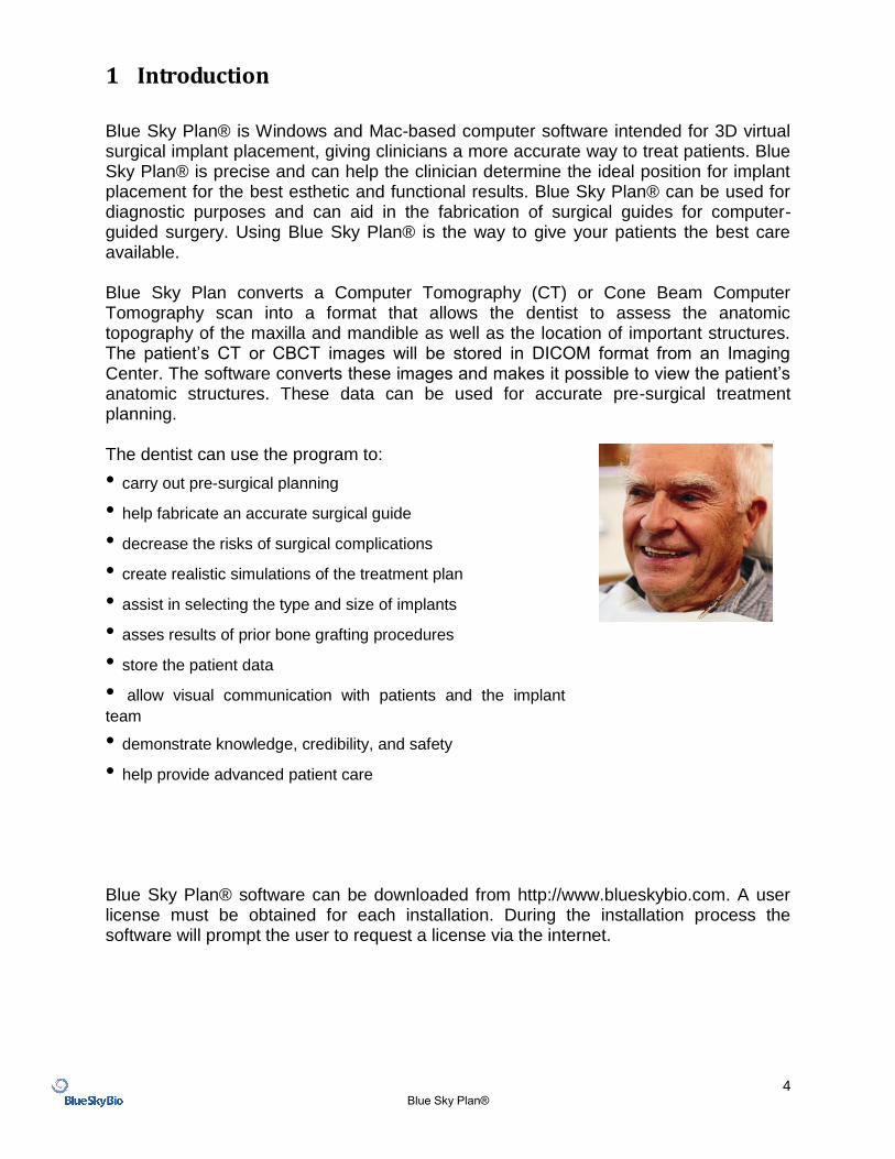
Blue Sky Plan® is Windows and Mac-based computer software intended for 3D virtual surgical implant placement, giving clinicians a more accurate way to treat patients. Blue Sky Plan® is precise and can help the clinician determine the ideal position for implant placement for the best esthetic and functional results. Blue Sky Plan® can be used for diagnostic purposes and can aid in the fabrication of surgical guides for computer-guided surgery. Using Blue Sky Plan® is the way to give your patients the best care available. Blue Sky Plan converts a Computer Tomography (CT) or Cone Beam Computer Tomography scan into a format that allows the dentist to assess the anatomic topography of the maxilla and mandible as well as the location of important structures. The patient’s CT or CBCT images will be stored in DICOM format from an Imaging Center. The software converts these images and makes it possible to view the patient’s anatomic structures. These data can be used for accurate pre-surgical treatment planning. The dentist can use the program to:
• carry out pre-surgical planning
• help fabricate an accurate surgical guide
• decrease the risks of surgical complications
• create realistic simulations of the treatment plan
• assist in selecting the type and size of implants
• asses results of prior bone grafting procedures
• store the patient data
• allow visual communication with patients and the implant
team
• demonstrate knowledge, credibility, and safety
• help provide advanced patient care
Blue Sky Plan® software can be downloaded from http://www.blueskybio.com. A user license must be obtained for each installation. During the installation process the software will prompt the user to request a license via the internet.
5 Blue Sky Plan®
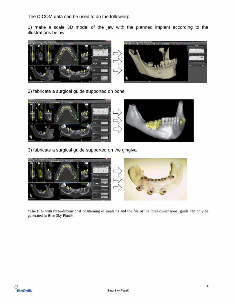
The DICOM data can be used to do the following: 1) make a scale 3D model of the jaw with the planned implant according to the illustrations below:
2) fabricate a surgical guide supported on bone
3) fabricate a surgical guide supported on the gingiva
*The files with three-dimensional positioning of implants and the file of the three-dimensional guide can only be
generated in Blue Sky Plan®.
6 Blue Sky Plan®
2 Installing Blue Sky Plan
Blue Sky Plan® software supports both Windows and Mac OS X operating systems.
Installation packages are available for the systems indicated.
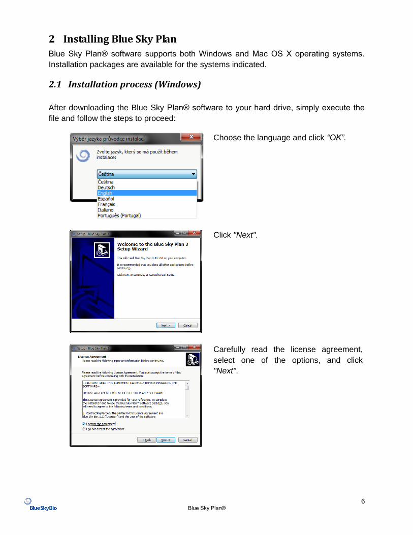
2.1 Installation process (Windows)
After downloading the Blue Sky Plan® software to your hard drive, simply execute the
file and follow the steps to proceed:
Choose the language and click “OK”.
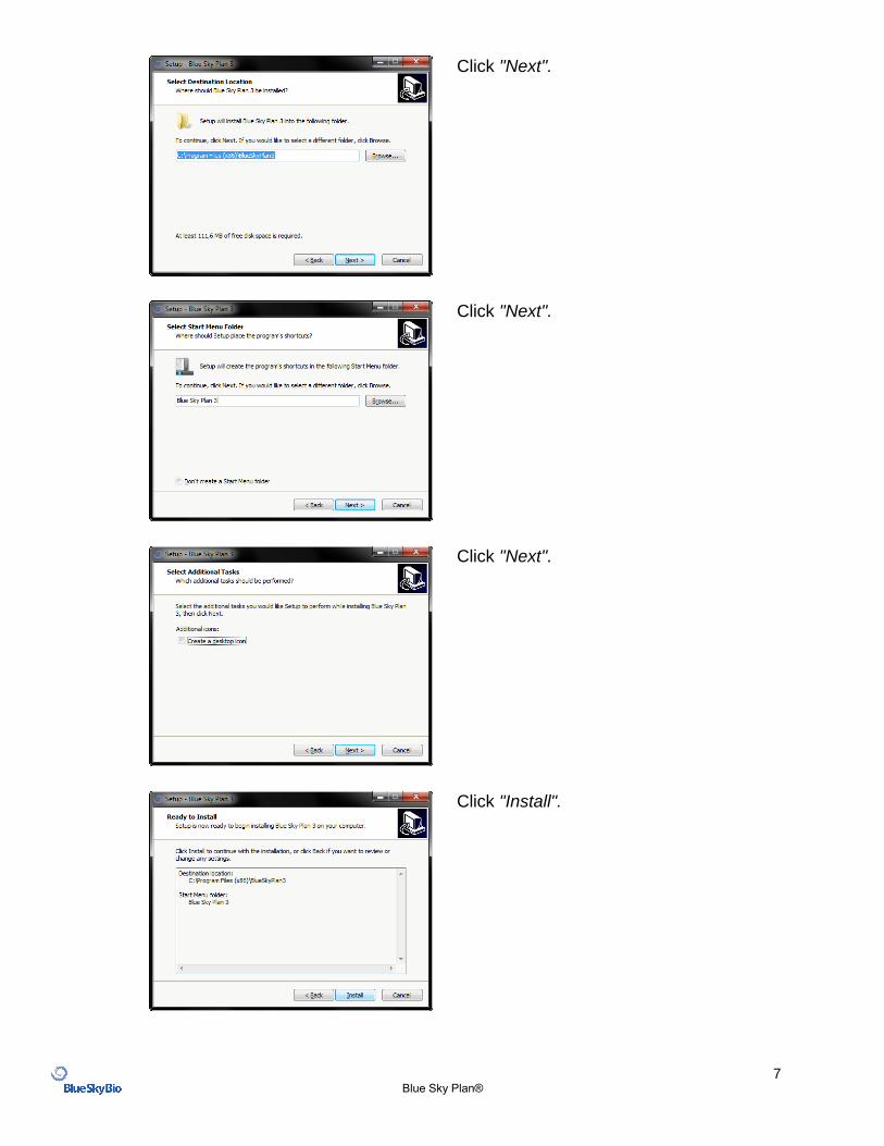
Click "Next".
Carefully read the license agreement,
select one of the options, and click
"Next".
7 Blue Sky Plan®
Click "Next".
Click "Next".
Click "Next".
Click "Install".
8 Blue Sky Plan®
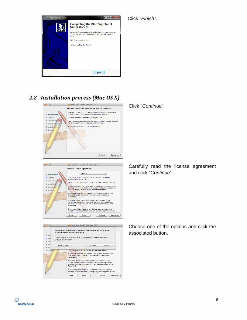
Click "Finish".
2.2 Installation process (Mac OS X)
Click "Continue".
Carefully read the license agreement
and click “Continue”.
Choose one of the options and click the
associated button.
9 Blue Sky Plan®
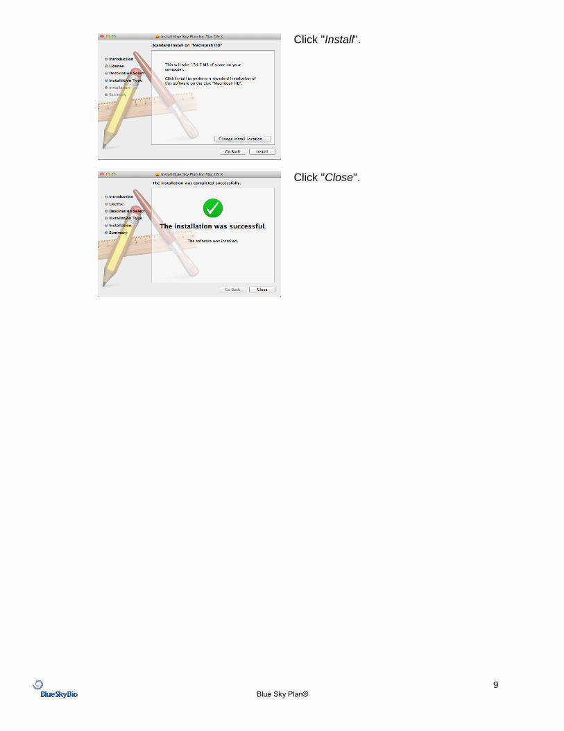
Click "Install".
Click "Close".
10 Blue Sky Plan®
2.3 Hardware requirements
General requirements:
Monitor: 14 inch, resolution of at least 1440 X 900
Hard Disk: 500MB of free space Minimum requirements:
Processor: dual core
RAM: 3 GB
Video card: NVidia or AMD, 512MB of video RAM (or Intel HD Graphics 4000) Recommended:
Processor: quad core
RAM: >4GB
Mid-range dedicated video card. NVidia or AMD, 1024MB of video RAM E.g. NVidia GeForce GTX 650, AMD Radeon HD 7750
2.4 Operating system
Windows 7 Home/Professional, or Mac OS X Lion/Mountain Lion.
11 Blue Sky Plan®
3 Loading the patient’s CT or CBCT scan into Blue Sky Plan
Blue Sky Plan® can load uncompressed DICOM images (exported by all CT scanners) into the software. Blue Sky Plan is “self processing” allowing the user to directly import the DICOM images in a few easy steps. A complete scanning protocol is available via the Blue Sky Bio website and can be sent to the scan site.
3.1 Selecting the DICOM images location
To import the patient’s CT or CBCT images, follow these steps:
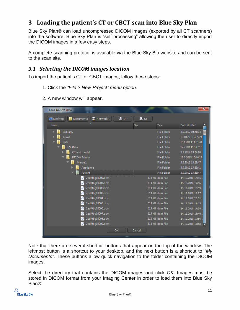
1. Click the “File > New Project” menu option.
2. A new window will appear.
Note that there are several shortcut buttons that appear on the top of the window. The leftmost button is a shortcut to your desktop, and the next button is a shortcut to “My Documents”. These buttons allow quick navigation to the folder containing the DICOM images. Select the directory that contains the DICOM images and click OK. Images must be stored in DICOM format from your Imaging Center in order to load them into Blue Sky Plan®.
12 Blue Sky Plan®
3.2 Selecting the series
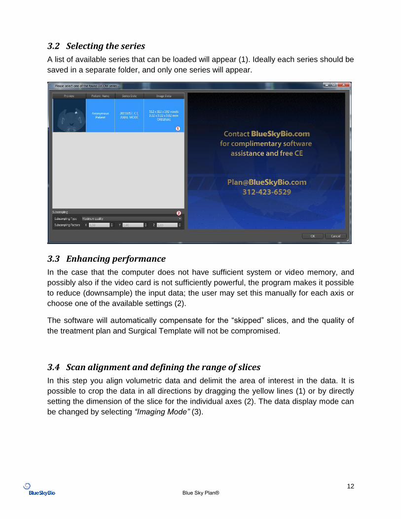
A list of available series that can be loaded will appear (1). Ideally each series should be
saved in a separate folder, and only one series will appear.
3.3 Enhancing performance
In the case that the computer does not have sufficient system or video memory, and
possibly also if the video card is not sufficiently powerful, the program makes it possible
to reduce (downsample) the input data; the user may set this manually for each axis or
choose one of the available settings (2).
The software will automatically compensate for the “skipped” slices, and the quality of
the treatment plan and Surgical Template will not be compromised.
3.4 Scan alignment and defining the range of slices
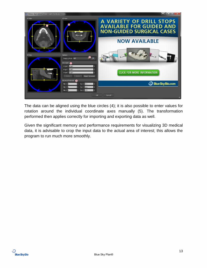
In this step you align volumetric data and delimit the area of interest in the data. It is
possible to crop the data in all directions by dragging the yellow lines (1) or by directly
setting the dimension of the slice for the individual axes (2). The data display mode can
be changed by selecting “Imaging Mode” (3).
13 Blue Sky Plan®
The data can be aligned using the blue circles (4); it is also possible to enter values for
rotation around the individual coordinate axes manually (5). The transformation
performed then applies correctly for importing and exporting data as well.
Given the significant memory and performance requirements for visualizing 3D medical
data, it is advisable to crop the input data to the actual area of interest; this allows the
program to run much more smoothly.
14 Blue Sky Plan®
3.5 Positioning the panoramic curve
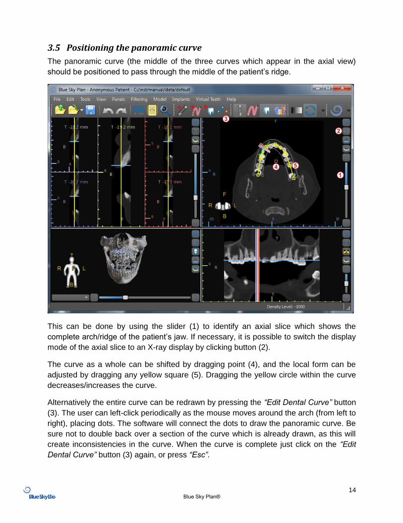
The panoramic curve (the middle of the three curves which appear in the axial view)
should be positioned to pass through the middle of the patient’s ridge.
This can be done by using the slider (1) to identify an axial slice which shows the
complete arch/ridge of the patient’s jaw. If necessary, it is possible to switch the display
mode of the axial slice to an X-ray display by clicking button (2).
The curve as a whole can be shifted by dragging point (4), and the local form can be
adjusted by dragging any yellow square (5). Dragging the yellow circle within the curve
decreases/increases the curve.
Alternatively the entire curve can be redrawn by pressing the “Edit Dental Curve” button
(3). The user can left-click periodically as the mouse moves around the arch (from left to
right), placing dots. The software will connect the dots to draw the panoramic curve. Be
sure not to double back over a section of the curve which is already drawn, as this will
create inconsistencies in the curve. When the curve is complete just click on the “Edit
Dental Curve” button (3) again, or press “Esc”.
15 Blue Sky Plan®
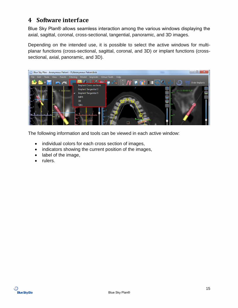
4 Software interface
Blue Sky Plan® allows seamless interaction among the various windows displaying the
axial, sagittal, coronal, cross-sectional, tangential, panoramic, and 3D images.
Depending on the intended use, it is possible to select the active windows for multi-
planar functions (cross-sectional, sagittal, coronal, and 3D) or implant functions (cross-
sectional, axial, panoramic, and 3D).
The following information and tools can be viewed in each active window:
individual colors for each cross section of images,
indicators showing the current position of the images,
label of the image,
rulers.
16 Blue Sky Plan®
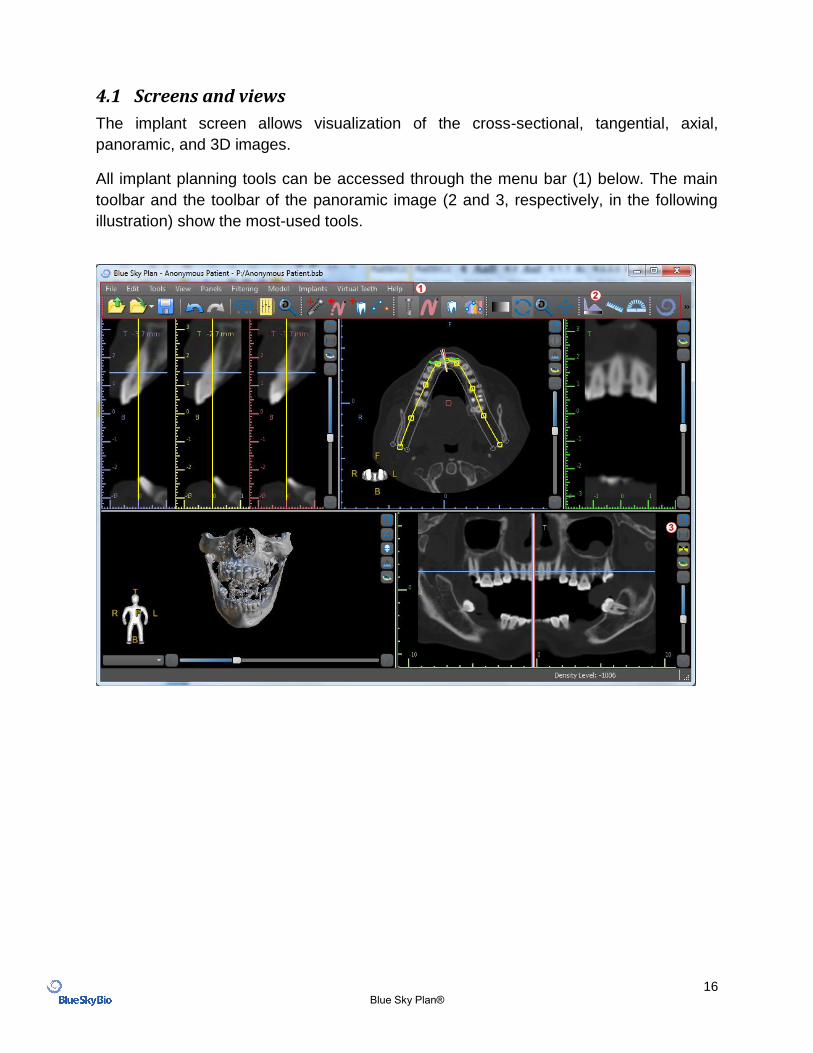
4.1 Screens and views
The implant screen allows visualization of the cross-sectional, tangential, axial,
panoramic, and 3D images.
All implant planning tools can be accessed through the menu bar (1) below. The main
toolbar and the toolbar of the panoramic image (2 and 3, respectively, in the following
illustration) show the most-used tools.
17 Blue Sky Plan®
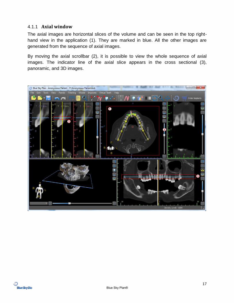
4.1.1 Axial window
The axial images are horizontal slices of the volume and can be seen in the top right-
hand view in the application (1). They are marked in blue. All the other images are
generated from the sequence of axial images.
By moving the axial scrollbar (2), it is possible to view the whole sequence of axial
images. The indicator line of the axial slice appears in the cross sectional (3),
panoramic, and 3D images.
18 Blue Sky Plan®
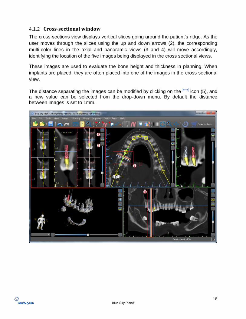
4.1.2 Cross-sectional window
The cross-sections view displays vertical slices going around the patient’s ridge. As the
user moves through the slices using the up and down arrows (2), the corresponding
multi-color lines in the axial and panoramic views (3 and 4) will move accordingly,
identifying the location of the five images being displayed in the cross sectional views.
These images are used to evaluate the bone height and thickness in planning. When
implants are placed, they are often placed into one of the images in the-cross sectional
view.
The distance separating the images can be modified by clicking on the icon (5), and a new value can be selected from the drop-down menu. By default the distance between images is set to 1mm.
19 Blue Sky Plan®
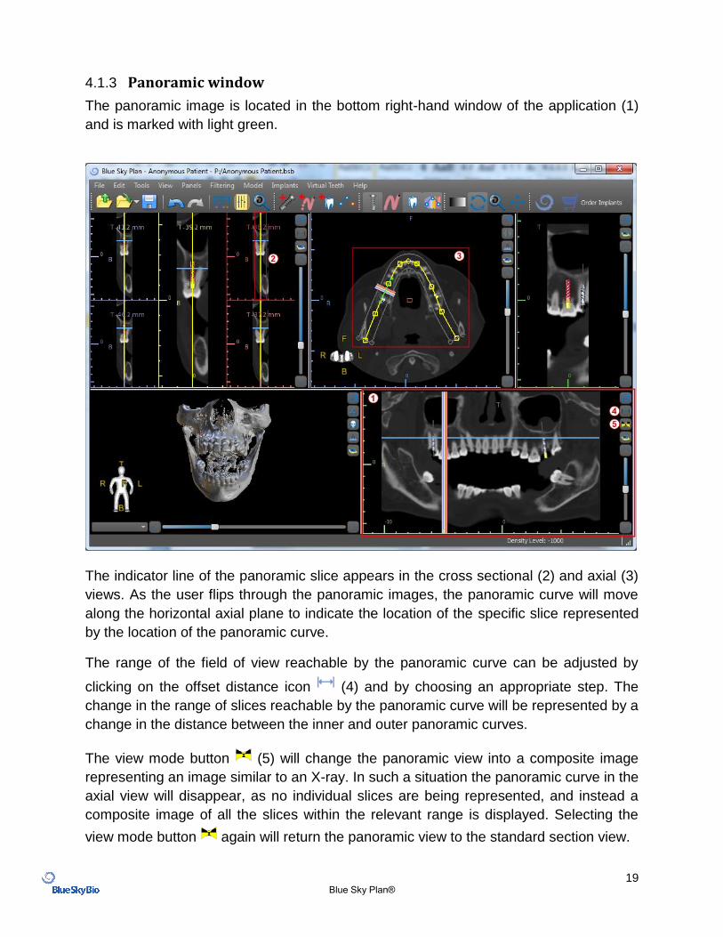
4.1.3 Panoramic window
The panoramic image is located in the bottom right-hand window of the application (1)
and is marked with light green.
The indicator line of the panoramic slice appears in the cross sectional (2) and axial (3)
views. As the user flips through the panoramic images, the panoramic curve will move
along the horizontal axial plane to indicate the location of the specific slice represented
by the location of the panoramic curve.
The range of the field of view reachable by the panoramic curve can be adjusted by
clicking on the offset distance icon (4) and by choosing an appropriate step. The
change in the range of slices reachable by the panoramic curve will be represented by a
change in the distance between the inner and outer panoramic curves.
The view mode button (5) will change the panoramic view into a composite image
representing an image similar to an X-ray. In such a situation the panoramic curve in the
axial view will disappear, as no individual slices are being represented, and instead a
composite image of all the slices within the relevant range is displayed. Selecting the
view mode button again will return the panoramic view to the standard section view.
20 Blue Sky Plan®
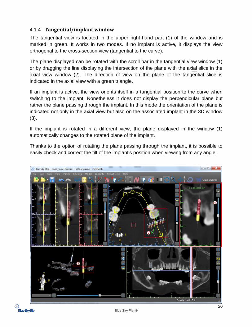
4.1.4 Tangential/implant window
The tangential view is located in the upper right-hand part (1) of the window and is
marked in green. It works in two modes. If no implant is active, it displays the view
orthogonal to the cross-section view (tangential to the curve).
The plane displayed can be rotated with the scroll bar in the tangential view window (1)
or by dragging the line displaying the intersection of the plane with the axial slice in the
axial view window (2). The direction of view on the plane of the tangential slice is
indicated in the axial view with a green triangle.
If an implant is active, the view orients itself in a tangential position to the curve when
switching to the implant. Nonetheless it does not display the perpendicular plane but
rather the plane passing through the implant. In this mode the orientation of the plane is
indicated not only in the axial view but also on the associated implant in the 3D window
(3).
If the implant is rotated in a different view, the plane displayed in the window (1)
automatically changes to the rotated plane of the implant.
Thanks to the option of rotating the plane passing through the implant, it is possible to
easily check and correct the tilt of the implant's position when viewing from any angle.
21 Blue Sky Plan®
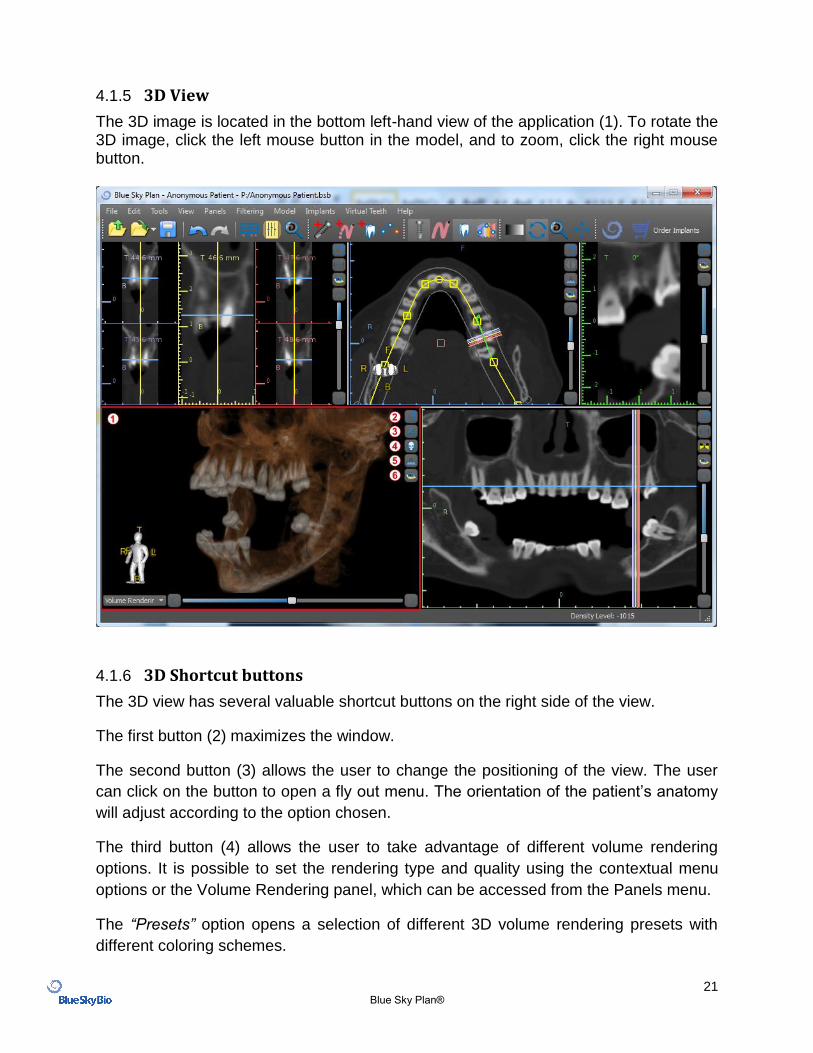
4.1.5 3D View
The 3D image is located in the bottom left-hand view of the application (1). To rotate the 3D image, click the left mouse button in the model, and to zoom, click the right mouse button.
4.1.6 3D Shortcut buttons
The 3D view has several valuable shortcut buttons on the right side of the view.
The first button (2) maximizes the window.
The second button (3) allows the user to change the positioning of the view. The user
can click on the button to open a fly out menu. The orientation of the patient’s anatomy
will adjust according to the option chosen.
The third button (4) allows the user to take advantage of different volume rendering
options. It is possible to set the rendering type and quality using the contextual menu
options or the Volume Rendering panel, which can be accessed from the Panels menu.
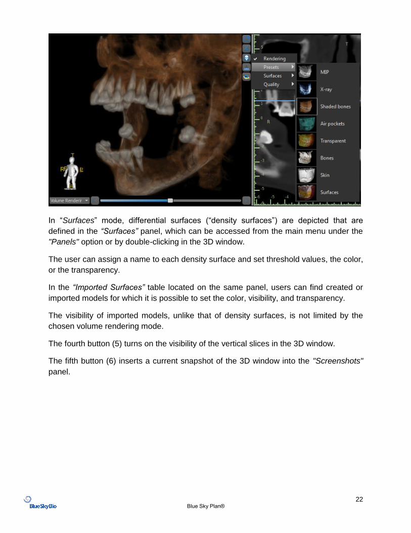
The “Presets” option opens a selection of different 3D volume rendering presets with
different coloring schemes.
22 Blue Sky Plan®
In “Surfaces” mode, differential surfaces (“density surfaces”) are depicted that are
defined in the “Surfaces” panel, which can be accessed from the main menu under the
"Panels" option or by double-clicking in the 3D window.
The user can assign a name to each density surface and set threshold values, the color,
or the transparency.
In the “Imported Surfaces” table located on the same panel, users can find created or
imported models for which it is possible to set the color, visibility, and transparency.
The visibility of imported models, unlike that of density surfaces, is not limited by the
chosen volume rendering mode.
The fourth button (5) turns on the visibility of the vertical slices in the 3D window.
The fifth button (6) inserts a current snapshot of the 3D window into the "Screenshots"
panel.
23 Blue Sky Plan®
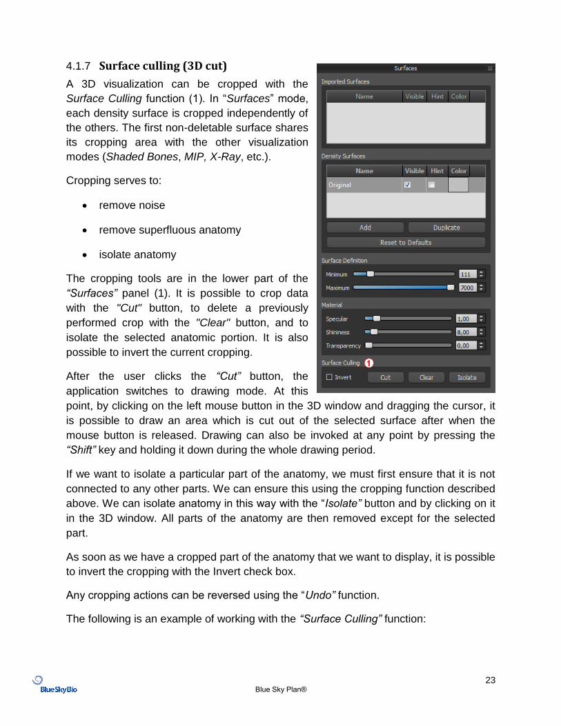
4.1.7 Surface culling (3D cut)
A 3D visualization can be cropped with the
Surface Culling function (1). In “Surfaces” mode,
each density surface is cropped independently of
the others. The first non-deletable surface shares
its cropping area with the other visualization
modes (Shaded Bones, MIP, X-Ray, etc.).
Cropping serves to:
remove noise
remove superfluous anatomy
isolate anatomy
The cropping tools are in the lower part of the
“Surfaces” panel (1). It is possible to crop data
with the "Cut" button, to delete a previously
performed crop with the "Clear" button, and to
isolate the selected anatomic portion. It is also
possible to invert the current cropping.
After the user clicks the “Cut” button, the
application switches to drawing mode. At this
point, by clicking on the left mouse button in the 3D window and dragging the cursor, it
is possible to draw an area which is cut out of the selected surface after when the
mouse button is released. Drawing can also be invoked at any point by pressing the
“Shift” key and holding it down during the whole drawing period.
If we want to isolate a particular part of the anatomy, we must first ensure that it is not
connected to any other parts. We can ensure this using the cropping function described
above. We can isolate anatomy in this way with the “Isolate” button and by clicking on it
in the 3D window. All parts of the anatomy are then removed except for the selected
part.
As soon as we have a cropped part of the anatomy that we want to display, it is possible
to invert the cropping with the Invert check box.
Any cropping actions can be reversed using the “Undo” function.
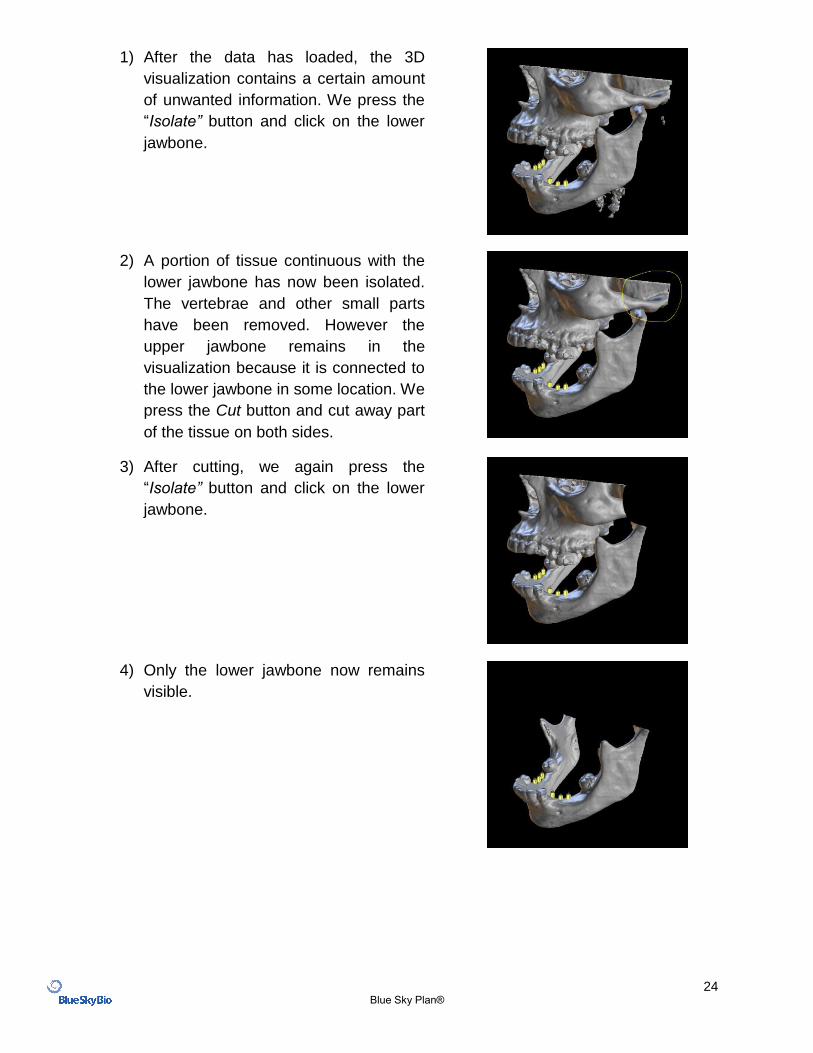
The following is an example of working with the “Surface Culling” function:
24 Blue Sky Plan®
1) After the data has loaded, the 3D
visualization contains a certain amount
of unwanted information. We press the
“Isolate” button and click on the lower
jawbone.
2) A portion of tissue continuous with the
lower jawbone has now been isolated.
The vertebrae and other small parts
have been removed. However the
upper jawbone remains in the
visualization because it is connected to
the lower jawbone in some location. We
press the Cut button and cut away part
of the tissue on both sides.
3) After cutting, we again press the
“Isolate” button and click on the lower
jawbone.
4) Only the lower jawbone now remains
visible.
25 Blue Sky Plan®
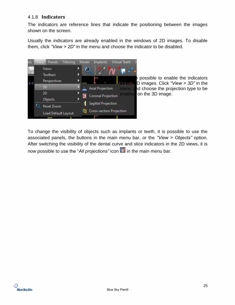
4.1.8 Indicators
The indicators are reference lines that indicate the positioning between the images
shown on the screen.
Usually the indicators are already enabled in the windows of 2D images. To disable
them, click “View > 2D” in the menu and choose the indicator to be disabled.
It is also possible to enable the indicators on the 3D images. Click “View > 3D” in the menu and choose the projection type to be enabled on the 3D image.
To change the visibility of objects such as implants or teeth, it is possible to use the
associated panels, the buttons in the main menu bar, or the “View > Objects” option.
After switching the visibility of the dental curve and slice indicators in the 2D views, it is
now possible to use the “All projections” icon in the main menu bar.
26 Blue Sky Plan®
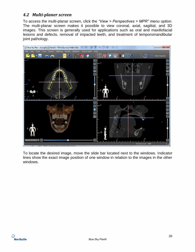
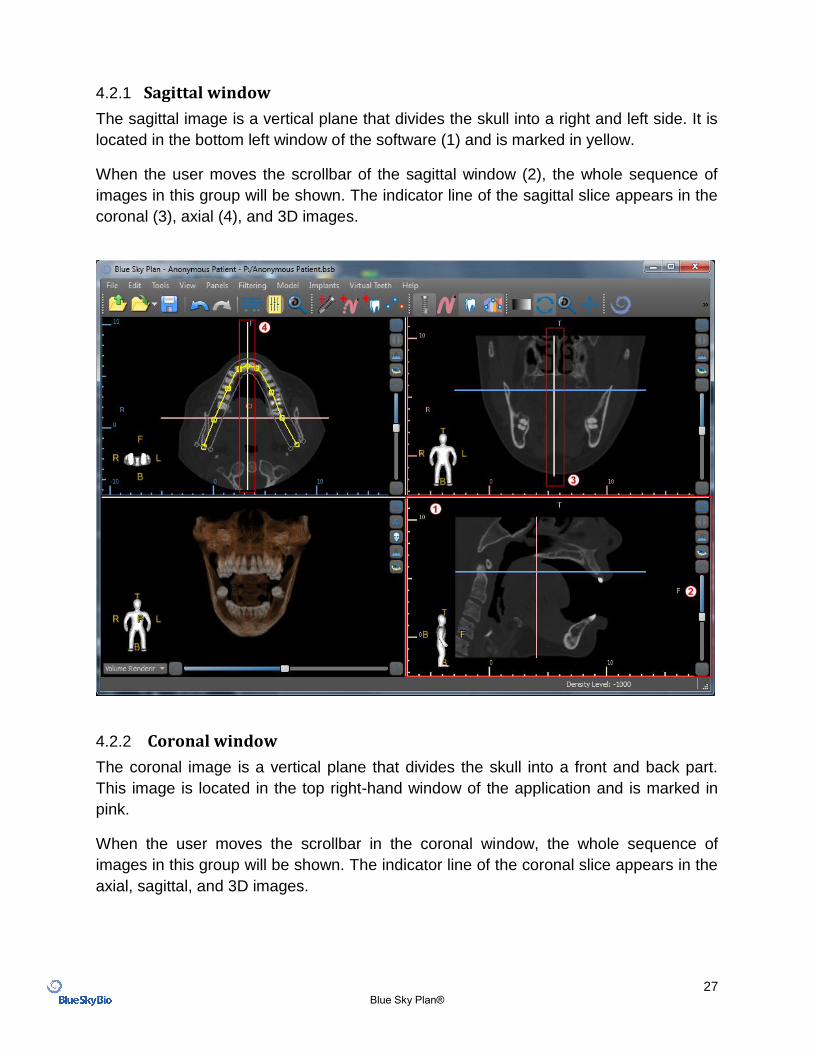
4.2 Multi-planer screen
To access the multi-planar screen, click the “View > Perspectives > MPR” menu option. The multi-planar screen makes it possible to view coronal, axial, sagittal, and 3D images. This screen is generally used for applications such as oral and maxillofacial lesions and defects, removal of impacted teeth, and treatment of temporomandibular joint pathology.
To locate the desired image, move the slide bar located next to the windows. Indicator lines show the exact image position of one window in relation to the images in the other windows.
27 Blue Sky Plan®
4.2.1 Sagittal window
The sagittal image is a vertical plane that divides the skull into a right and left side. It is
located in the bottom left window of the software (1) and is marked in yellow.
When the user moves the scrollbar of the sagittal window (2), the whole sequence of
images in this group will be shown. The indicator line of the sagittal slice appears in the
coronal (3), axial (4), and 3D images.
4.2.2 Coronal window
The coronal image is a vertical plane that divides the skull into a front and back part.
This image is located in the top right-hand window of the application and is marked in
pink.
When the user moves the scrollbar in the coronal window, the whole sequence of
images in this group will be shown. The indicator line of the coronal slice appears in the
axial, sagittal, and 3D images.
28 Blue Sky Plan®
5 Placing implants and pins
Blue Sky Plan® allows virtual implant planning via the patient’s CT or CBCT images. It is possible to add, exchange, move, and rotate the implant and abutment or pin in the different views.
5.1 Adding an implant or pin
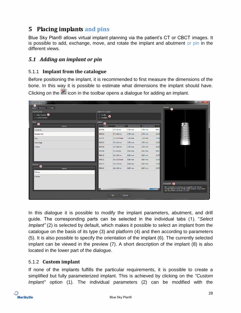
5.1.1 Implant from the catalogue
Before positioning the implant, it is recommended to first measure the dimensions of the
bone. In this way it is possible to estimate what dimensions the implant should have.
Clicking on the icon in the toolbar opens a dialogue for adding an implant.
In this dialogue it is possible to modify the implant parameters, abutment, and drill
guide. The corresponding parts can be selected in the individual tabs (1). “Select
Implant” (2) is selected by default, which makes it possible to select an implant from the
catalogue on the basis of its type (3) and platform (4) and then according to parameters
(5). It is also possible to specify the orientation of the implant (6). The currently selected
implant can be viewed in the preview (7). A short description of the implant (8) is also
located in the lower part of the dialogue.
5.1.2 Custom implant
If none of the implants fulfills the particular requirements, it is possible to create a
simplified but fully parameterized implant. This is achieved by clicking on the "Custom
Implant" option (1). The individual parameters (2) can be modified with the
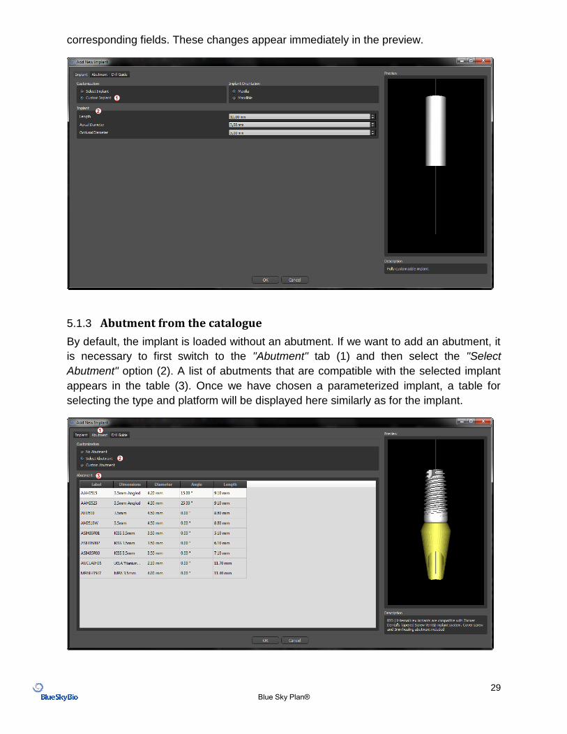
29 Blue Sky Plan®
corresponding fields. These changes appear immediately in the preview.
5.1.3 Abutment from the catalogue
By default, the implant is loaded without an abutment. If we want to add an abutment, it
is necessary to first switch to the "Abutment" tab (1) and then select the "Select
Abutment" option (2). A list of abutments that are compatible with the selected implant
appears in the table (3). Once we have chosen a parameterized implant, a table for
selecting the type and platform will be displayed here similarly as for the implant.
30 Blue Sky Plan®
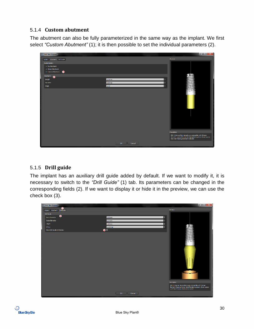
5.1.4 Custom abutment
The abutment can also be fully parameterized in the same way as the implant. We first
select “Custom Abutment” (1); it is then possible to set the individual parameters (2).
5.1.5 Drill guide
The implant has an auxiliary drill guide added by default. If we want to modify it, it is
necessary to switch to the “Drill Guide” (1) tab. Its parameters can be changed in the
corresponding fields (2). If we want to display it or hide it in the preview, we can use the
check box (3).
31 Blue Sky Plan®
5.1.6 Pin from the catalogue
Instead of an implant, it is possible to add a pin. This is a special implant for positioning
a template more firmly. In contrast to an implant, it cannot have an abutment but only a
drill guide.
5.1.7 Your own pin
It is also possible to adjust your own pin similarly as for previous parts. Length 0 sets
the length of the blue part of the pin; length 1 then sets the length of the green part.
5.2 Positioning and manipulating the implant
We confirm the choice of implant in the dialogue by pressing “OK”. The mouse cursor
then changes to . We can then position the implant by clicking on the slice and, if
necessary, on the 3D visualization in any window. After being added, the implant is
always positioned perpendicular to the selected orientation. It is up to the user to fine-
tune the position and rotation.
It is possible to move the implant in all of the windows. This is achieved by moving the
cursor onto the implant, clicking the left mouse button, and dragging. The implant
always moves in the plane of the view.
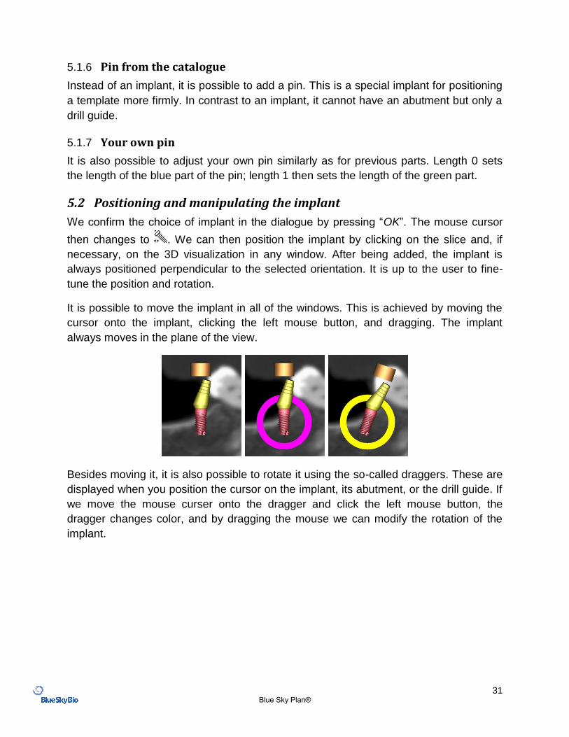
Besides moving it, it is also possible to rotate it using the so-called draggers. These are
displayed when you position the cursor on the implant, its abutment, or the drill guide. If
we move the mouse curser onto the dragger and click the left mouse button, the
dragger changes color, and by dragging the mouse we can modify the rotation of the
implant.

32 Blue Sky Plan®
If the implant has a parameterized abutment, it is
possible to change the angle of the abutment with the
spherical blue-green dragger.
In the 3D window, the situation is a little more
complicated because, unlike the other windows, the
implant is manipulated in space. Three circles of different
colors appear around the implant, which rotate it around
the associated axes of the local coordinate system.
Besides these, arrows appear both above and below the
implant, by means of which it is possible to move the
implant on its axis.
It should be added that clicking on the implant makes the implant active, and all the
slices move onto it. It is possible to recognize it in the windows by its red coloring. The
other implants are colored light blue.
5.3 Further operations on the implant
5.3.1 Toolbar
In the upper menu bar it is possible to display a toolbar of further operations on the
implant by selecting “View > Toolbars > Implants Toolbar”. Here there are icons for
removing the implant (1), replacing the implant (2), and displaying information about the
implant (3).
All of these operations are used in the same way: we click on the icon, move the cursor
onto the implant, and click on it. For the option of replacing the implant, the same
dialogue appears as when adding the implant, in which we choose which implant we
want to replace the selected implant with.
33 Blue Sky Plan®
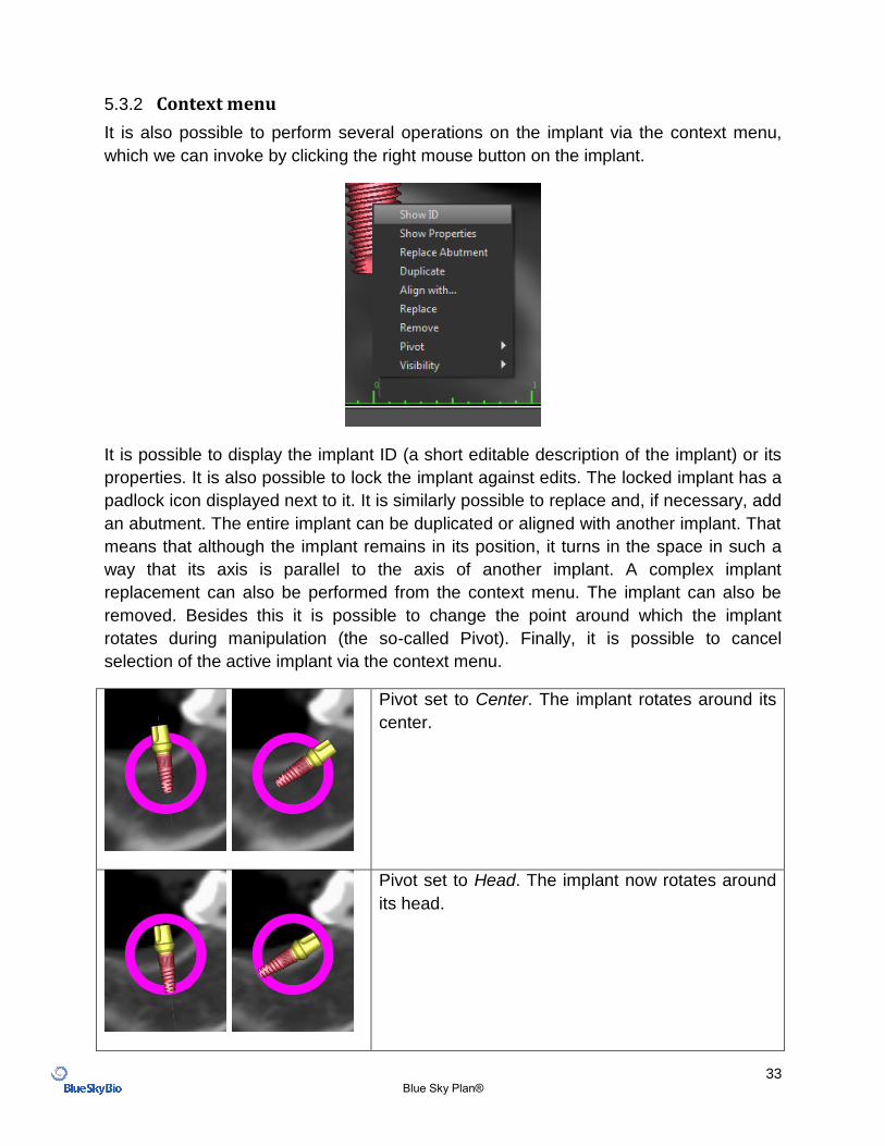
5.3.2 Context menu
It is also possible to perform several operations on the implant via the context menu,
which we can invoke by clicking the right mouse button on the implant.
It is possible to display the implant ID (a short editable description of the implant) or its
properties. It is also possible to lock the implant against edits. The locked implant has a
padlock icon displayed next to it. It is similarly possible to replace and, if necessary, add
an abutment. The entire implant can be duplicated or aligned with another implant. That
means that although the implant remains in its position, it turns in the space in such a
way that its axis is parallel to the axis of another implant. A complex implant
replacement can also be performed from the context menu. The implant can also be
removed. Besides this it is possible to change the point around which the implant
rotates during manipulation (the so-called Pivot). Finally, it is possible to cancel
selection of the active implant via the context menu.
Pivot set to Center. The implant rotates around its
center.
Pivot set to Head. The implant now rotates around
its head.
34 Blue Sky Plan®
Finally, the visibility of individual parts of the implant can be changed (“Visibility >
Implant/Abutment/Drill Guide”).
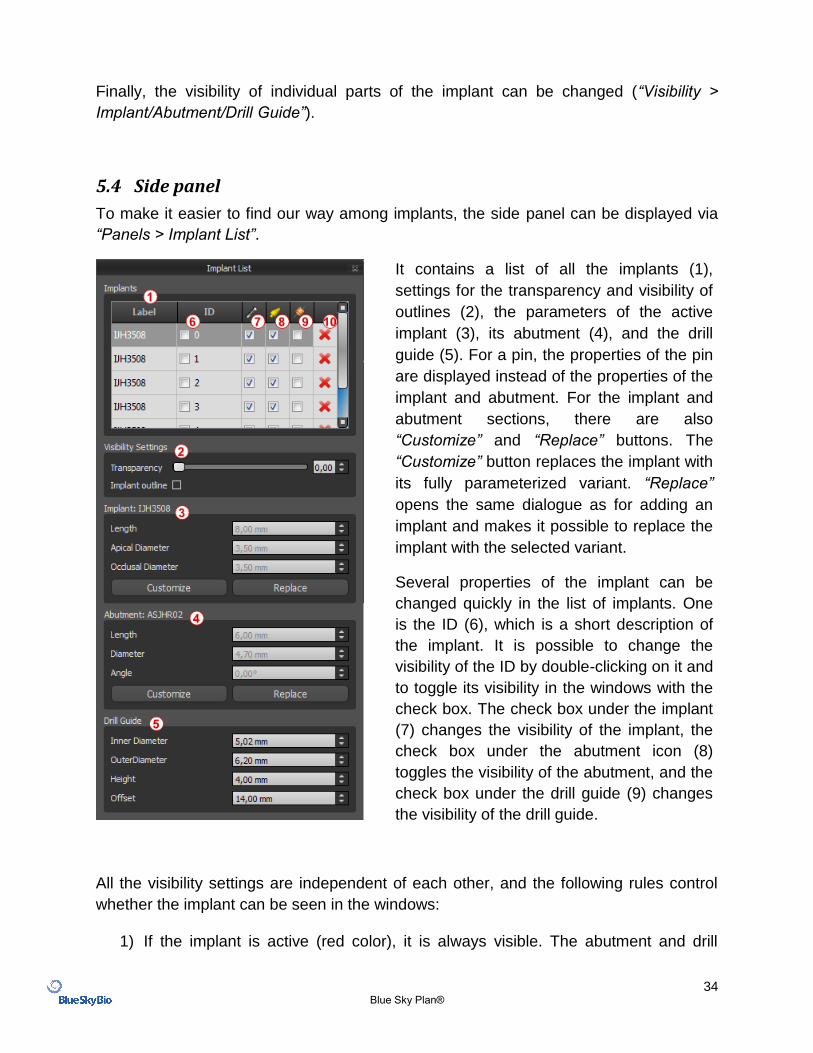
5.4 Side panel
To make it easier to find our way among implants, the side panel can be displayed via
“Panels > Implant List”.
It contains a list of all the implants (1),
settings for the transparency and visibility of
outlines (2), the parameters of the active
implant (3), its abutment (4), and the drill
guide (5). For a pin, the properties of the pin
are displayed instead of the properties of the
implant and abutment. For the implant and
abutment sections, there are also
“Customize” and “Replace” buttons. The
“Customize” button replaces the implant with
its fully parameterized variant. “Replace”
opens the same dialogue as for adding an
implant and makes it possible to replace the
implant with the selected variant.
Several properties of the implant can be
changed quickly in the list of implants. One
is the ID (6), which is a short description of
the implant. It is possible to change the
visibility of the ID by double-clicking on it and
to toggle its visibility in the windows with the
check box. The check box under the implant
(7) changes the visibility of the implant, the
check box under the abutment icon (8)
toggles the visibility of the abutment, and the
check box under the drill guide (9) changes
the visibility of the drill guide.
All the visibility settings are independent of each other, and the following rules control
whether the implant can be seen in the windows:
1) If the implant is active (red color), it is always visible. The abutment and drill
35 Blue Sky Plan®
guide are controlled by the check boxes.
2) If the mouse cursor is positioned over the implant, its abutment, or the drill guide,
the draggers and the implant are displayed. The abutment and drill guide are
controlled by the check boxes.
3) In all other cases, the visibility of the individual parts is controlled by the check
boxes.
Finally, for every implant there is an icon for removing it (10) and locking it (between drill
guide and deletion).
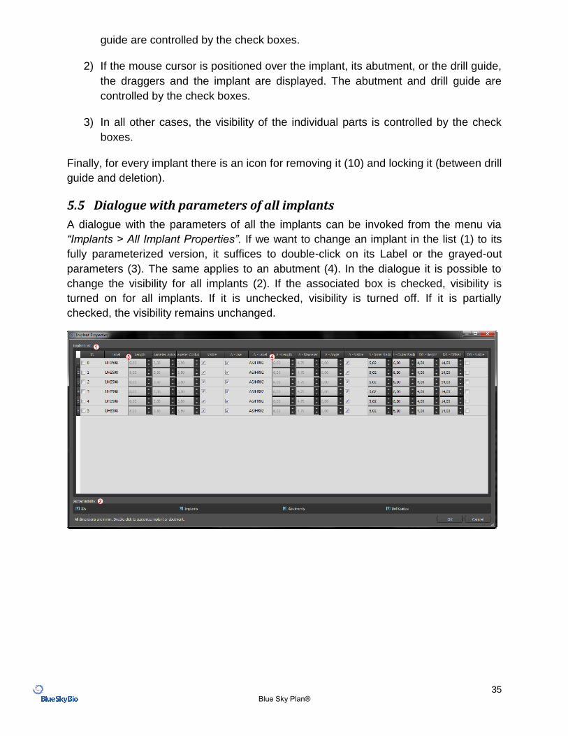
5.5 Dialogue with parameters of all implants
A dialogue with the parameters of all the implants can be invoked from the menu via
“Implants > All Implant Properties”. If we want to change an implant in the list (1) to its
fully parameterized version, it suffices to double-click on its Label or the grayed-out
parameters (3). The same applies to an abutment (4). In the dialogue it is possible to
change the visibility for all implants (2). If the associated box is checked, visibility is
turned on for all implants. If it is unchecked, visibility is turned off. If it is partially
checked, the visibility remains unchanged.
36 Blue Sky Plan®
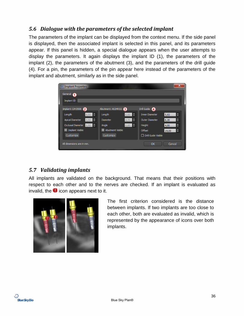
5.6 Dialogue with the parameters of the selected implant
The parameters of the implant can be displayed from the context menu. If the side panel
is displayed, then the associated implant is selected in this panel, and its parameters
appear. If this panel is hidden, a special dialogue appears when the user attempts to
display the parameters. It again displays the implant ID (1), the parameters of the
implant (2), the parameters of the abutment (3), and the parameters of the drill guide
(4). For a pin, the parameters of the pin appear here instead of the parameters of the
implant and abutment, similarly as in the side panel.
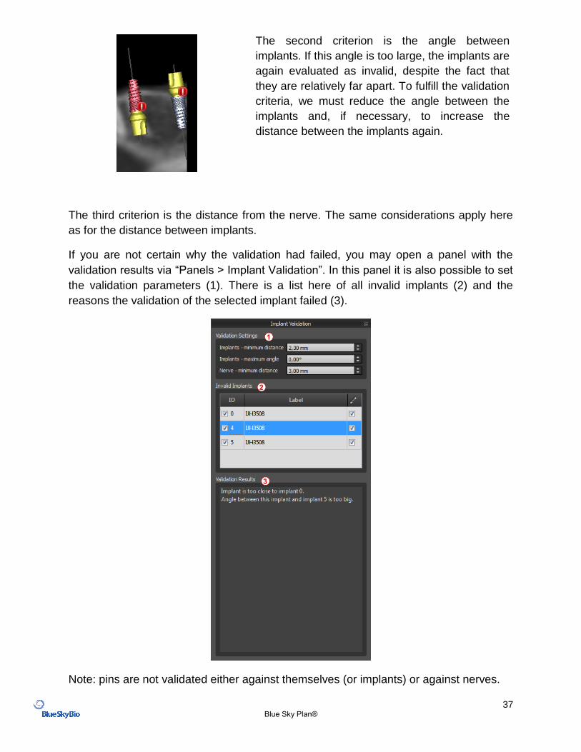
5.7 Validating implants
All implants are validated on the background. That means that their positions with
respect to each other and to the nerves are checked. If an implant is evaluated as
invalid, the icon appears next to it.
The first criterion considered is the distance
between implants. If two implants are too close to
each other, both are evaluated as invalid, which is
represented by the appearance of icons over both
implants.
37 Blue Sky Plan®
The second criterion is the angle between
implants. If this angle is too large, the implants are
again evaluated as invalid, despite the fact that
they are relatively far apart. To fulfill the validation
criteria, we must reduce the angle between the
implants and, if necessary, to increase the
distance between the implants again.
The third criterion is the distance from the nerve. The same considerations apply here
as for the distance between implants.
If you are not certain why the validation had failed, you may open a panel with the
validation results via “Panels > Implant Validation”. In this panel it is also possible to set
the validation parameters (1). There is a list here of all invalid implants (2) and the
reasons the validation of the selected implant failed (3).
Note: pins are not validated either against themselves (or implants) or against nerves.
38 Blue Sky Plan®
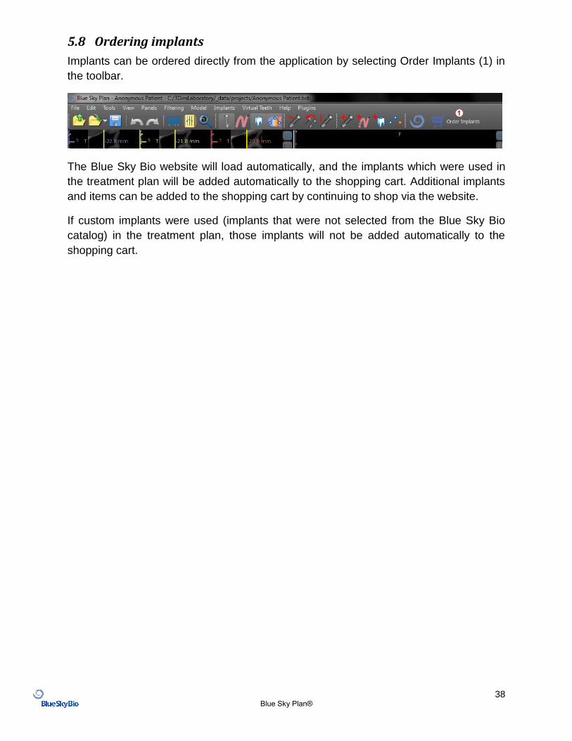
5.8 Ordering implants
Implants can be ordered directly from the application by selecting Order Implants (1) in
the toolbar.
The Blue Sky Bio website will load automatically, and the implants which were used in
the treatment plan will be added automatically to the shopping cart. Additional implants
and items can be added to the shopping cart by continuing to shop via the website.
If custom implants were used (implants that were not selected from the Blue Sky Bio
catalog) in the treatment plan, those implants will not be added automatically to the
shopping cart.
39 Blue Sky Plan®
6 Tools
This chapter explains the properties of each Blue Sky Plan® tool and the toolbar that contains the most-used tools in the application.
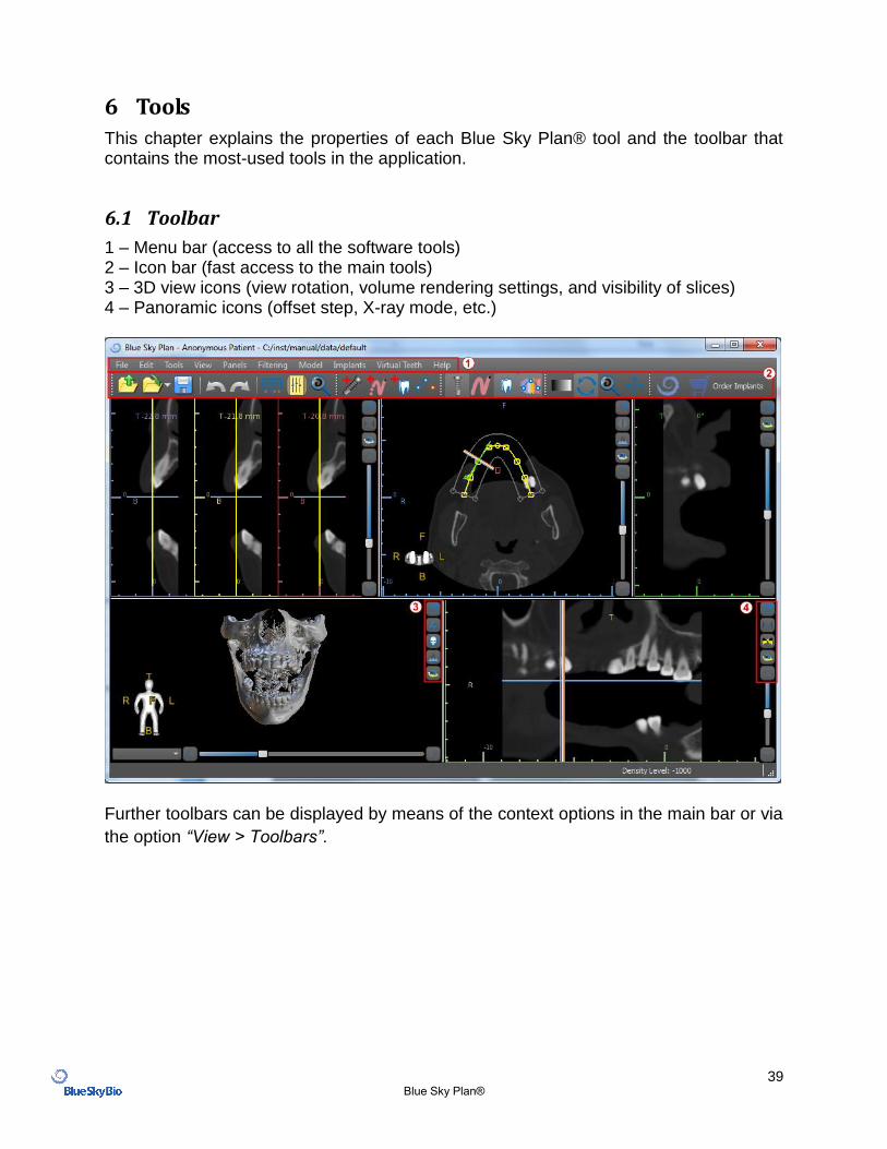
6.1 Toolbar
1 – Menu bar (access to all the software tools) 2 – Icon bar (fast access to the main tools) 3 – 3D view icons (view rotation, volume rendering settings, and visibility of slices) 4 – Panoramic icons (offset step, X-ray mode, etc.)
Further toolbars can be displayed by means of the context options in the main bar or via
the option “View > Toolbars”.
40 Blue Sky Plan®
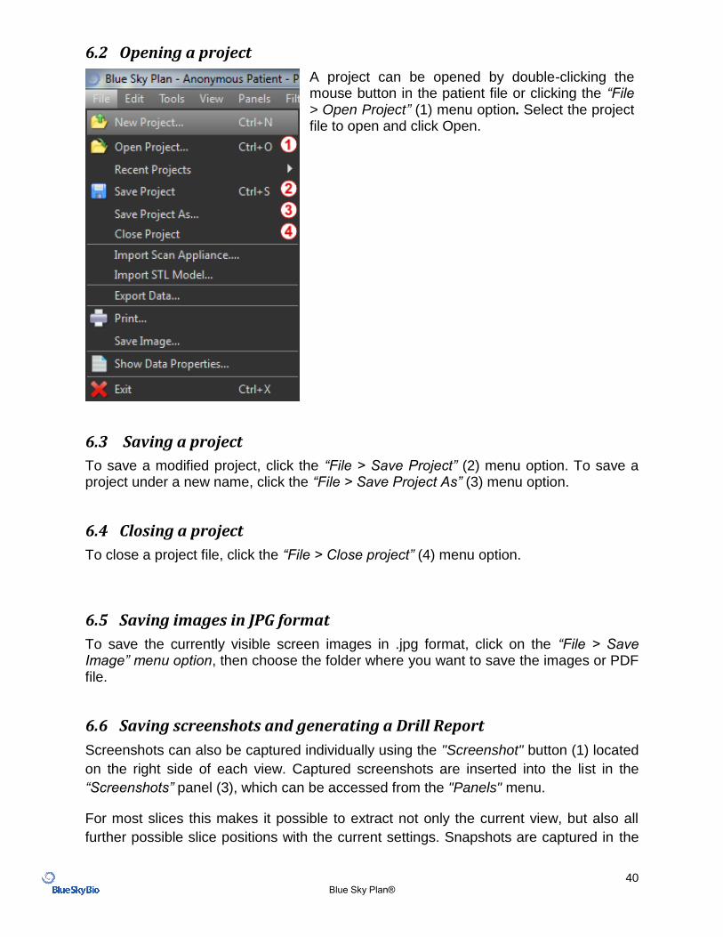
6.2 Opening a project
A project can be opened by double-clicking the mouse button in the patient file or clicking the “File > Open Project” (1) menu option. Select the project file to open and click Open.
6.3 Saving a project
To save a modified project, click the “File > Save Project” (2) menu option. To save a project under a new name, click the “File > Save Project As” (3) menu option.
6.4 Closing a project
To close a project file, click the “File > Close project” (4) menu option.
6.5 Saving images in JPG format
To save the currently visible screen images in .jpg format, click on the “File > Save Image” menu option, then choose the folder where you want to save the images or PDF file.
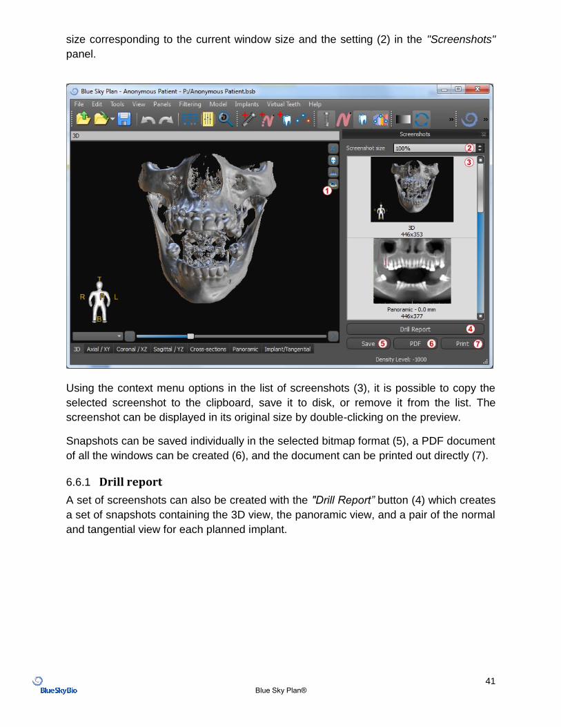
6.6 Saving screenshots and generating a Drill Report
Screenshots can also be captured individually using the "Screenshot" button (1) located
on the right side of each view. Captured screenshots are inserted into the list in the
“Screenshots” panel (3), which can be accessed from the "Panels" menu.
For most slices this makes it possible to extract not only the current view, but also all
further possible slice positions with the current settings. Snapshots are captured in the
41 Blue Sky Plan®
size corresponding to the current window size and the setting (2) in the "Screenshots"
panel.
Using the context menu options in the list of screenshots (3), it is possible to copy the
selected screenshot to the clipboard, save it to disk, or remove it from the list. The
screenshot can be displayed in its original size by double-clicking on the preview.
Snapshots can be saved individually in the selected bitmap format (5), a PDF document
of all the windows can be created (6), and the document can be printed out directly (7).
6.6.1 Drill report
A set of screenshots can also be created with the "Drill Report” button (4) which creates
a set of snapshots containing the 3D view, the panoramic view, and a pair of the normal
and tangential view for each planned implant.
42 Blue Sky Plan®
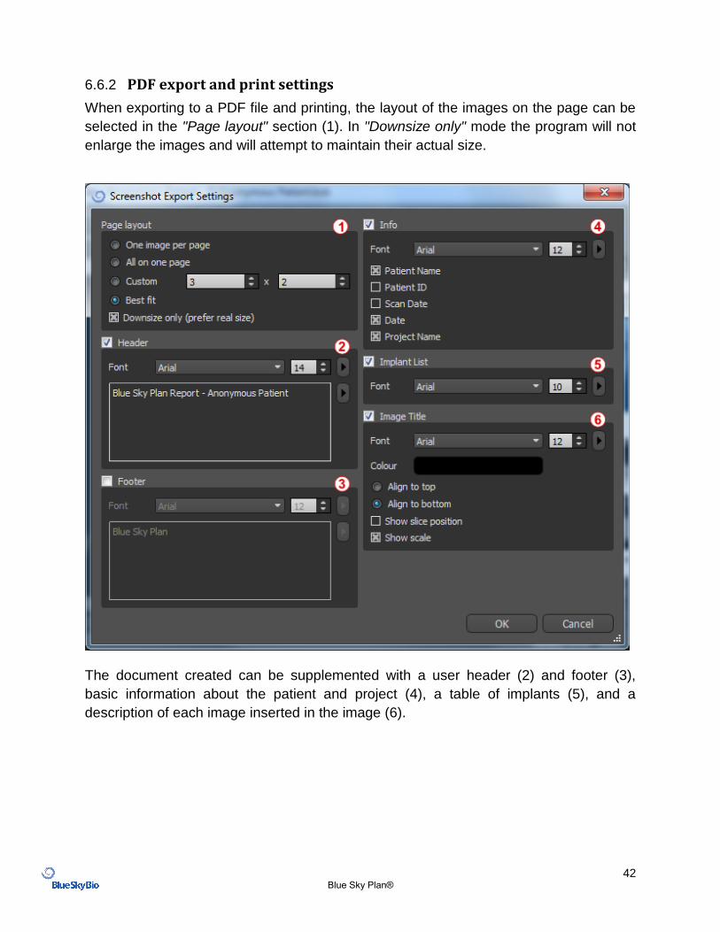
6.6.2 PDF export and print settings
When exporting to a PDF file and printing, the layout of the images on the page can be
selected in the "Page layout" section (1). In "Downsize only" mode the program will not
enlarge the images and will attempt to maintain their actual size.
The document created can be supplemented with a user header (2) and footer (3),
basic information about the patient and project (4), a table of implants (5), and a
description of each image inserted in the image (6).
43 Blue Sky Plan®
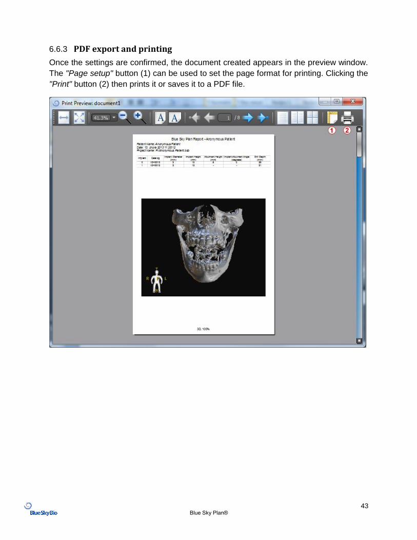
6.6.3 PDF export and printing
Once the settings are confirmed, the document created appears in the preview window.
The "Page setup" button (1) can be used to set the page format for printing. Clicking the
"Print" button (2) then prints it or saves it to a PDF file.
44 Blue Sky Plan®
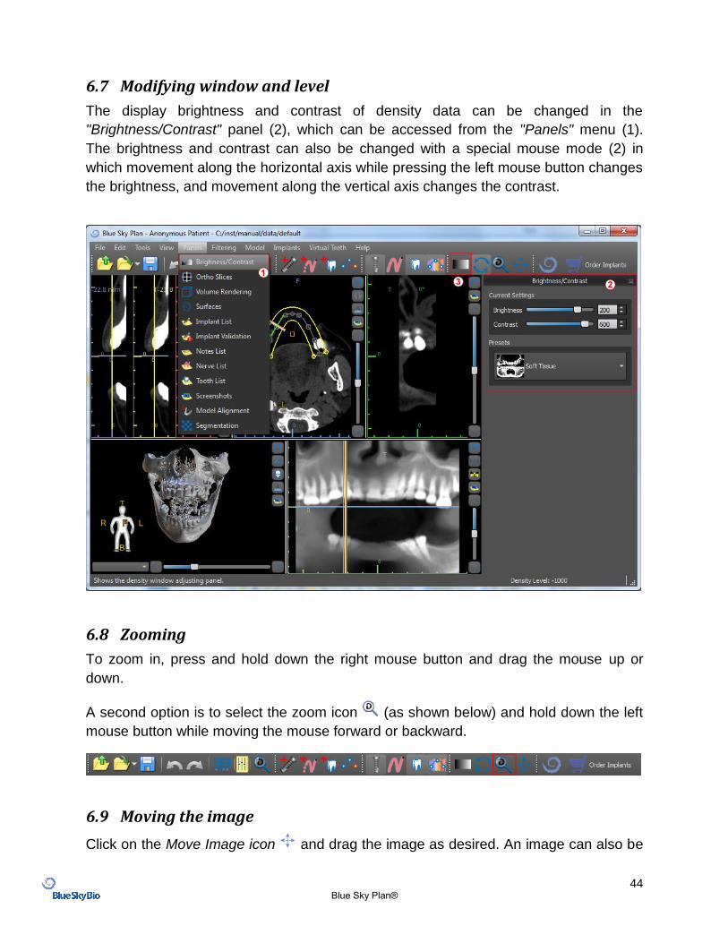
6.7 Modifying window and level
The display brightness and contrast of density data can be changed in the
"Brightness/Contrast" panel (2), which can be accessed from the "Panels" menu (1).
The brightness and contrast can also be changed with a special mouse mode (2) in
which movement along the horizontal axis while pressing the left mouse button changes
the brightness, and movement along the vertical axis changes the contrast.
6.8 Zooming
To zoom in, press and hold down the right mouse button and drag the mouse up or
down.
A second option is to select the zoom icon (as shown below) and hold down the left
mouse button while moving the mouse forward or backward.
6.9 Moving the image
Click on the Move Image icon and drag the image as desired. An image can also be
45 Blue Sky Plan®
moved by holding down the mouse wheel (pressing it, not scrolling it) and dragging the
image.
6.10 Moving objects
In the default mouse mode, left-clicking changes the position of the slice. If the mouse
cursor is positioned over an object that can be manipulated, the mouse cursor changes,
and the object can be moved, and if necessary its angle of rotation or size can be
changed using the displayed dragger.
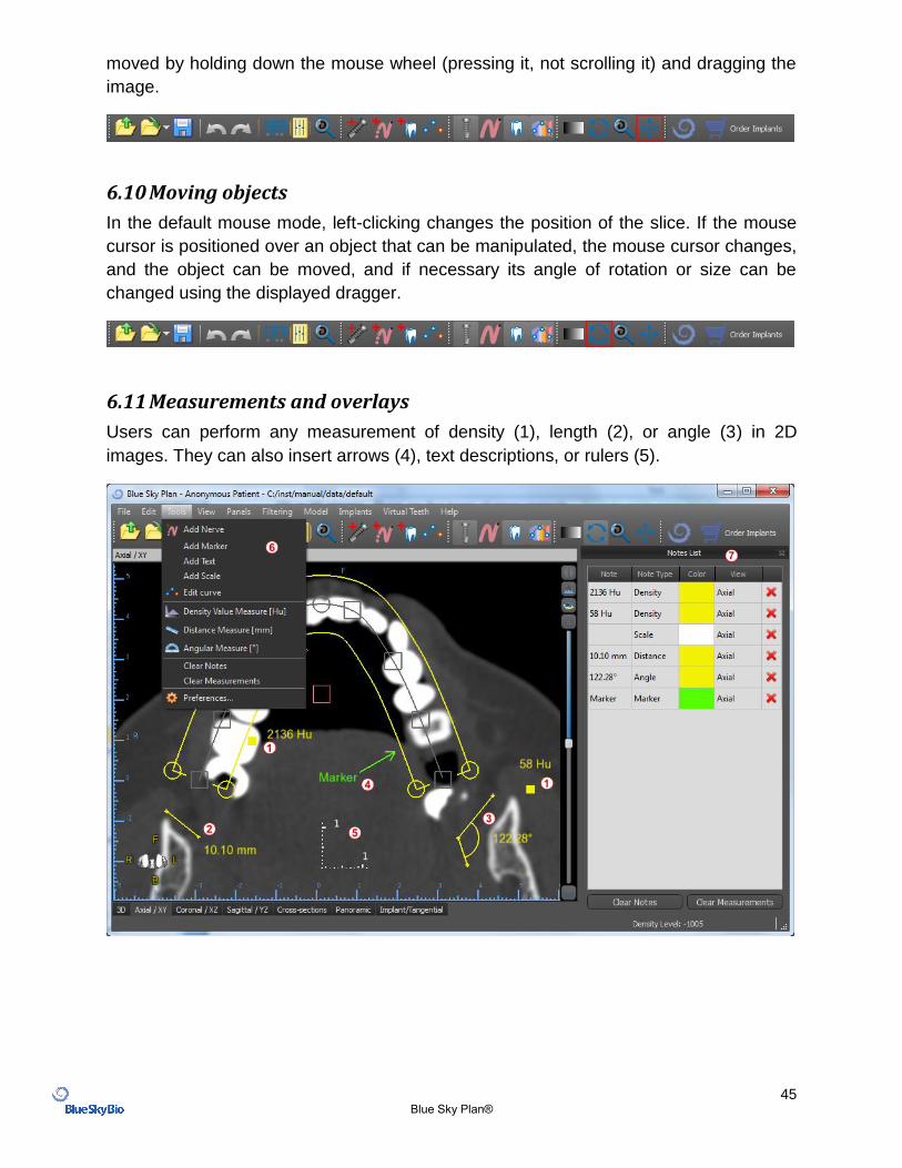
6.11 Measurements and overlays
Users can perform any measurement of density (1), length (2), or angle (3) in 2D
images. They can also insert arrows (4), text descriptions, or rulers (5).
46 Blue Sky Plan®
6.12 Linear measurement
Click the “Tools > Distance Measure” menu option (6) in order to perform any 2D
measurements (2).
Click the left mouse button with the pointer on the image to mark the start point of the distance to be measured and click again on the image to mark the end point of the measured distance. To correct the measurement you can grab one of the end points and move them.
6.13 Angular measurement
Click “Tools > Angular Measure” menu option (6). Click the left mouse button with the pointer on the image and repeat the process twice to get an angle (3). To correct the measurement you can grab the points specifying the angle.
6.14 Density measurement
Click the “Tools > Density Measure” menu option (6). The value of the density measurement is obtained from the information contained in the patient's image and can vary for each CT or CBCT scan. The measurements are given in Hounsfield units.
6.15 Measurement correction and number position
The user can correct the measurement and all the overlays in the default mouse mode. It is possible to correct a measurement by clicking at the edge of the measurement with the left mouse button and dragging. It is also possible to position the numerical value of the measurement outside of the image.
6.16 Deleting a measurement
It is possible to erase a measurement in two ways:
a) Click the measurement edge or click on the number with the right mouse button. A menu will appear with the deletion option.
b) Click the “Panels > Notes List” menu option. A panel will appear (7) with a list of all measurements, their types, values, and colors. To erase a measurement, click the X beside the measurement.
47 Blue Sky Plan®
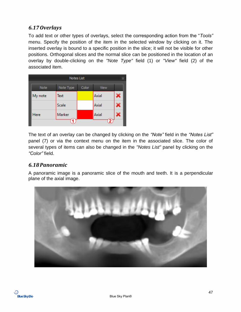
6.17 Overlays
To add text or other types of overlays, select the corresponding action from the “Tools”
menu. Specify the position of the item in the selected window by clicking on it. The
inserted overlay is bound to a specific position in the slice; it will not be visible for other
positions. Orthogonal slices and the normal slice can be positioned in the location of an
overlay by double-clicking on the "Note Type" field (1) or "View" field (2) of the
associated item.
The text of an overlay can be changed by clicking on the “Note” field in the “Notes List”
panel (7) or via the context menu on the item in the associated slice. The color of
several types of items can also be changed in the "Notes List" panel by clicking on the
“Color” field.
6.18 Panoramic
A panoramic image is a panoramic slice of the mouth and teeth. It is a perpendicular plane of the axial image.
48 Blue Sky Plan®
6.18.1 Creating a panoramic line
Refer to Section 3.3.
6.18.2 Mandibular canal
The mandibular canal can be added in the panoramic image and viewed in all of the
images.
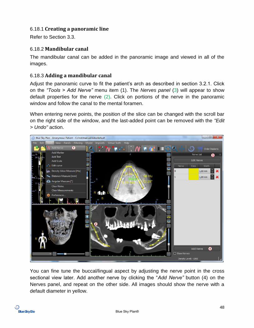
6.18.3 Adding a mandibular canal
Adjust the panoramic curve to fit the patient’s arch as described in section 3.2.1. Click
on the “Tools > Add Nerve” menu item (1). The Nerves panel (3) will appear to show
default properties for the nerve (2). Click on portions of the nerve in the panoramic
window and follow the canal to the mental foramen.
When entering nerve points, the position of the slice can be changed with the scroll bar
on the right side of the window, and the last-added point can be removed with the "Edit
> Undo" action.
You can fine tune the buccal/lingual aspect by adjusting the nerve point in the cross
sectional view later. Add another nerve by clicking the “Add Nerve” button (4) on the
Nerves panel, and repeat on the other side. All images should show the nerve with a
default diameter in yellow.
49 Blue Sky Plan®
6.18.4 Changing mandibular canal parameters
Clicking on the color of the nerve in the list (3) opens color selection window. After
choosing, confirm your selection by pressing “OK”. The width of the nerve is displayed
in the adjacent column. This can be changed either by clicking on the window and
entering new values or by repeatedly clicking on the arrows beside it to change the
value in increments of 0.1 mm.
6.18.5 Deleting the mandibular canal
Select the “Panels > Nerve List” menu option and click on the letter X beside the nerve to be deleted.
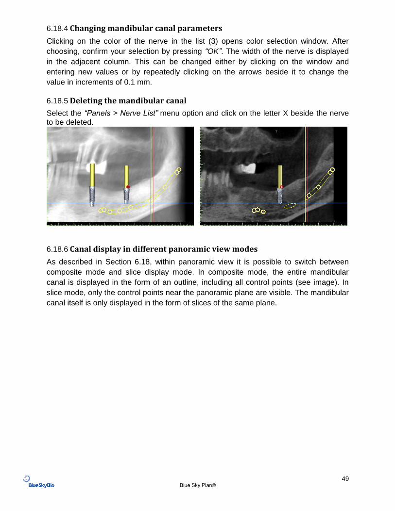
6.18.6 Canal display in different panoramic view modes
As described in Section 6.18, within panoramic view it is possible to switch between
composite mode and slice display mode. In composite mode, the entire mandibular
canal is displayed in the form of an outline, including all control points (see image). In
slice mode, only the control points near the panoramic plane are visible. The mandibular
canal itself is only displayed in the form of slices of the same plane.
50 Blue Sky Plan®
7 Importing the Scan Appliance
The Blue Sky Plan® Scanning Protocol calls for two CT scans. The first scan should be
of the patient wearing a Scan Appliance, and the second scan should be of just the
Scan Appliance. Since the Scan Appliance is made of mostly radiolucent material, the
Scan Appliance does not appear in the patient’s scan. It does however appear when
scanned alone, since the relevant density of the Scan Appliance is greater than the
density of air, causing it to appear in the scan.
The software allows the two scans to be merged in order to have the Scan Appliance
appear in the scan of the patient. Merging the Scan Appliance assists with proper
treatment planning as it shows the position of the future teeth and removes any artifacts
which may have previously appeared in the area of the teeth.
Follow the steps below to import the Scan Appliance:
1) Load the DICOM set of the patient into the Blue Sky Plan application.
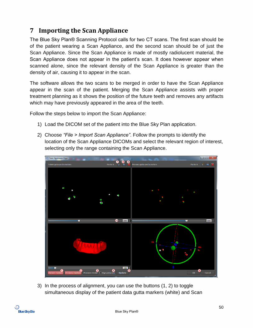
2) Choose “File > Import Scan Appliance”. Follow the prompts to identify the
location of the Scan Appliance DICOMs and select the relevant region of interest,
selecting only the range containing the Scan Appliance.
3) In the process of alignment, you can use the buttons (1, 2) to toggle
simultaneous display of the patient data gutta markers (white) and Scan
51 Blue Sky Plan®
Appliance (red). You can display or hide the Scan Appliance model with button
(3).
The top left-hand box contains the gutta markers from the patient’s scan. The top right-
hand box contains the gutta markers of the Scan Appliance. The bottom left-hand box
contains an image of the Scan Appliance. The bottom right-hand box displays both sets
of gutta markers if they coincide.
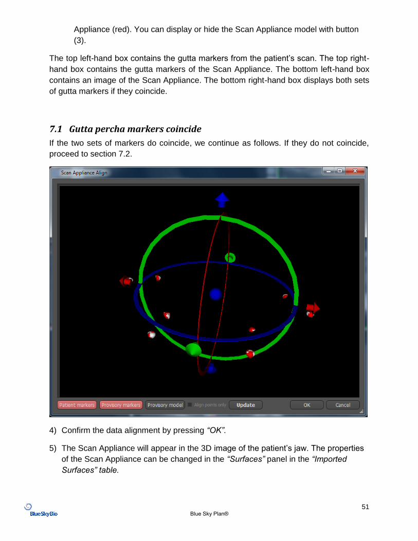
7.1 Gutta percha markers coincide
If the two sets of markers do coincide, we continue as follows. If they do not coincide,
proceed to section 7.2.
4) Confirm the data alignment by pressing “OK”.
5) The Scan Appliance will appear in the 3D image of the patient’s jaw. The properties
of the Scan Appliance can be changed in the “Surfaces” panel in the “Imported
Surfaces” table.
52 Blue Sky Plan®
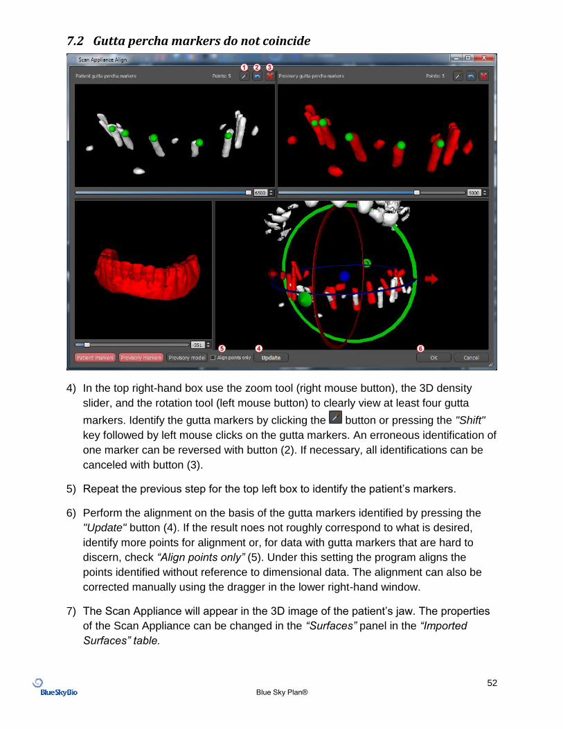
7.2 Gutta percha markers do not coincide
4) In the top right-hand box use the zoom tool (right mouse button), the 3D density
slider, and the rotation tool (left mouse button) to clearly view at least four gutta
markers. Identify the gutta markers by clicking the button or pressing the "Shift"
key followed by left mouse clicks on the gutta markers. An erroneous identification of
one marker can be reversed with button (2). If necessary, all identifications can be
canceled with button (3).
5) Repeat the previous step for the top left box to identify the patient’s markers.
6) Perform the alignment on the basis of the gutta markers identified by pressing the
"Update" button (4). If the result noes not roughly correspond to what is desired,
identify more points for alignment or, for data with gutta markers that are hard to
discern, check “Align points only” (5). Under this setting the program aligns the
points identified without reference to dimensional data. The alignment can also be
corrected manually using the dragger in the lower right-hand window.
7) The Scan Appliance will appear in the 3D image of the patient’s jaw. The properties
of the Scan Appliance can be changed in the “Surfaces” panel in the “Imported
Surfaces” table.
53 Blue Sky Plan®
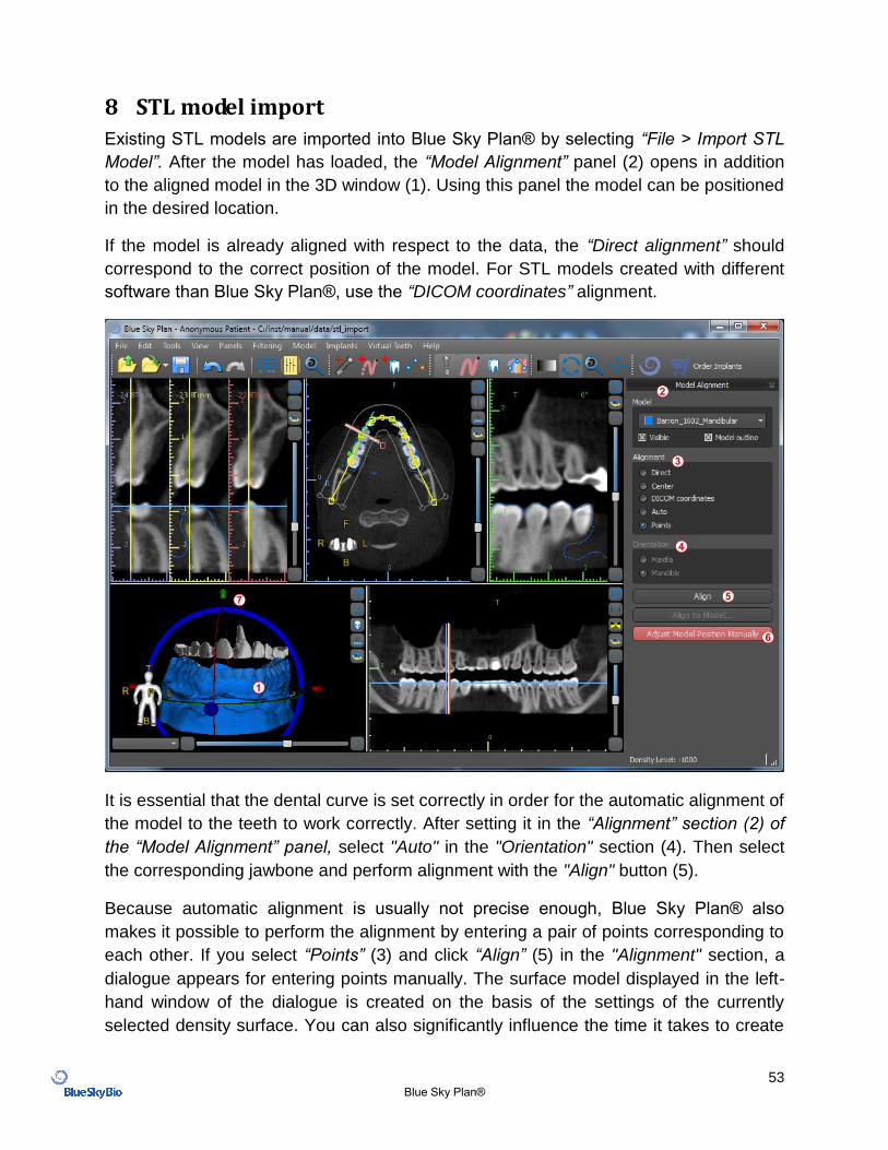
8 STL model import
Existing STL models are imported into Blue Sky Plan® by selecting “File > Import STL
Model”. After the model has loaded, the “Model Alignment” panel (2) opens in addition
to the aligned model in the 3D window (1). Using this panel the model can be positioned
in the desired location.
If the model is already aligned with respect to the data, the “Direct alignment” should
correspond to the correct position of the model. For STL models created with different
software than Blue Sky Plan®, use the “DICOM coordinates” alignment.
It is essential that the dental curve is set correctly in order for the automatic alignment of
the model to the teeth to work correctly. After setting it in the “Alignment” section (2) of
the “Model Alignment” panel, select "Auto" in the "Orientation" section (4). Then select
the corresponding jawbone and perform alignment with the "Align" button (5).
Because automatic alignment is usually not precise enough, Blue Sky Plan® also
makes it possible to perform the alignment by entering a pair of points corresponding to
each other. If you select “Points” (3) and click “Align” (5) in the "Alignment" section, a
dialogue appears for entering points manually. The surface model displayed in the left-
hand window of the dialogue is created on the basis of the settings of the currently
selected density surface. You can also significantly influence the time it takes to create
54 Blue Sky Plan®
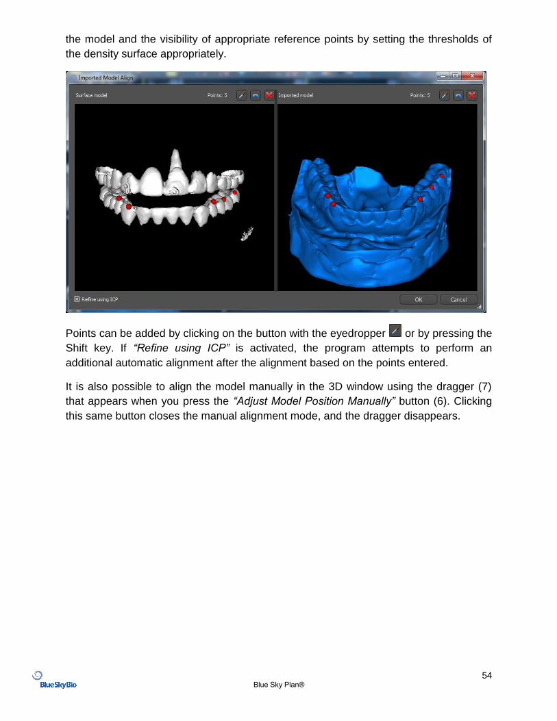
the model and the visibility of appropriate reference points by setting the thresholds of
the density surface appropriately.
Points can be added by clicking on the button with the eyedropper or by pressing the
Shift key. If “Refine using ICP” is activated, the program attempts to perform an
additional automatic alignment after the alignment based on the points entered.
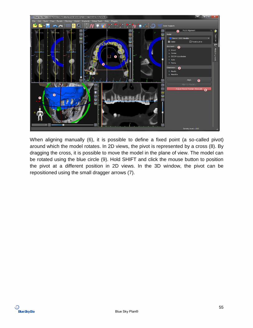
It is also possible to align the model manually in the 3D window using the dragger (7)
that appears when you press the “Adjust Model Position Manually” button (6). Clicking
this same button closes the manual alignment mode, and the dragger disappears.
55 Blue Sky Plan®
When aligning manually (6), it is possible to define a fixed point (a so-called pivot)
around which the model rotates. In 2D views, the pivot is represented by a cross (8). By
dragging the cross, it is possible to move the model in the plane of view. The model can
be rotated using the blue circle (9). Hold SHIFT and click the mouse button to position
the pivot at a different position in 2D views. In the 3D window, the pivot can be
repositioned using the small dragger arrows (7).
56 Blue Sky Plan®
9 Virtual teeth
Blue Sky Plan® makes it possible to insert "virtual" teeth into the project. Using pre-
prepared models of crowns inserted into the data, we can show the patient the possible
result after all planned procedures have been performed. Virtual teeth also make it
possible to align either a new or an existing implant and thus easily visually inspect the
respective position of the resulting crown with respect to the position of the implant and
to plan any abutment.
9.1 Inserting crowns
It is a good idea to first have a correctly specified dental curve, since the inserted crown
will be rotated automatically with respect to it. We insert the individual crowns either by
clicking on the icon in the toolbar or by using the button in the side panel (indicated
below), if necessary choosing the “Virtual Teeth > Add Tooth” menu item.
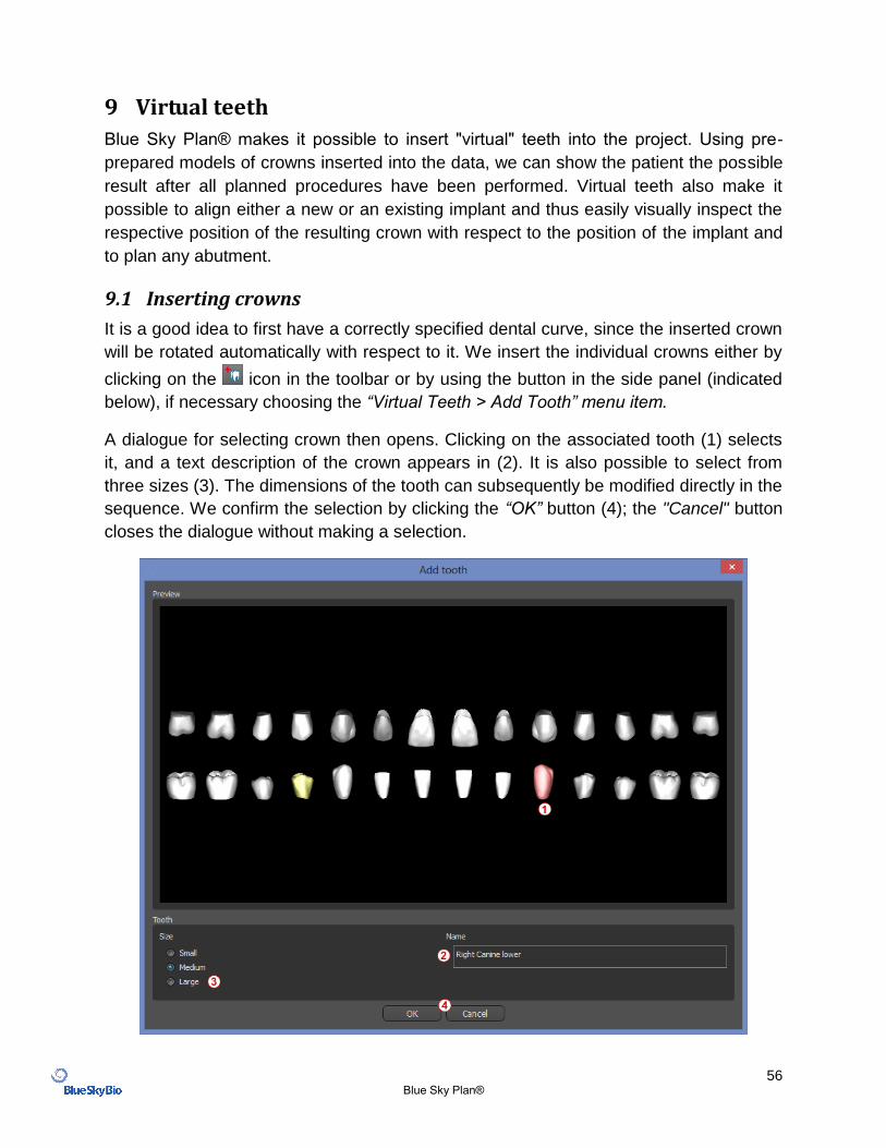
A dialogue for selecting crown then opens. Clicking on the associated tooth (1) selects
it, and a text description of the crown appears in (2). It is also possible to select from
three sizes (3). The dimensions of the tooth can subsequently be modified directly in the
sequence. We confirm the selection by clicking the “OK” button (4); the "Cancel" button
closes the dialogue without making a selection.
57 Blue Sky Plan®
9.2 Positioning the crown and manipulating it
The mouse cursor changes to a cross when the dialogue closes. We can then position
the crown by clicking on the slice, and if necessary on the 3D visualization in any
window. The crown is positioned in a vertical position according to the type of the
simulated tooth and rotates with respect to the dental curve. It is up to the user to fine-
tune its position.
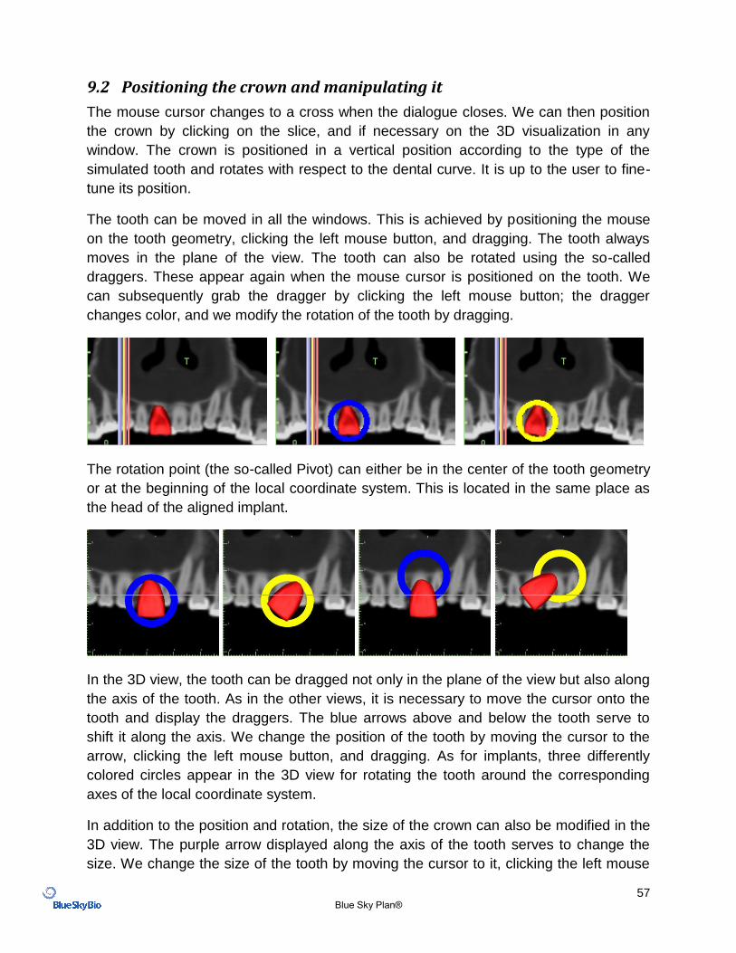
The tooth can be moved in all the windows. This is achieved by positioning the mouse
on the tooth geometry, clicking the left mouse button, and dragging. The tooth always
moves in the plane of the view. The tooth can also be rotated using the so-called
draggers. These appear again when the mouse cursor is positioned on the tooth. We
can subsequently grab the dragger by clicking the left mouse button; the dragger
changes color, and we modify the rotation of the tooth by dragging.
The rotation point (the so-called Pivot) can either be in the center of the tooth geometry
or at the beginning of the local coordinate system. This is located in the same place as
the head of the aligned implant.
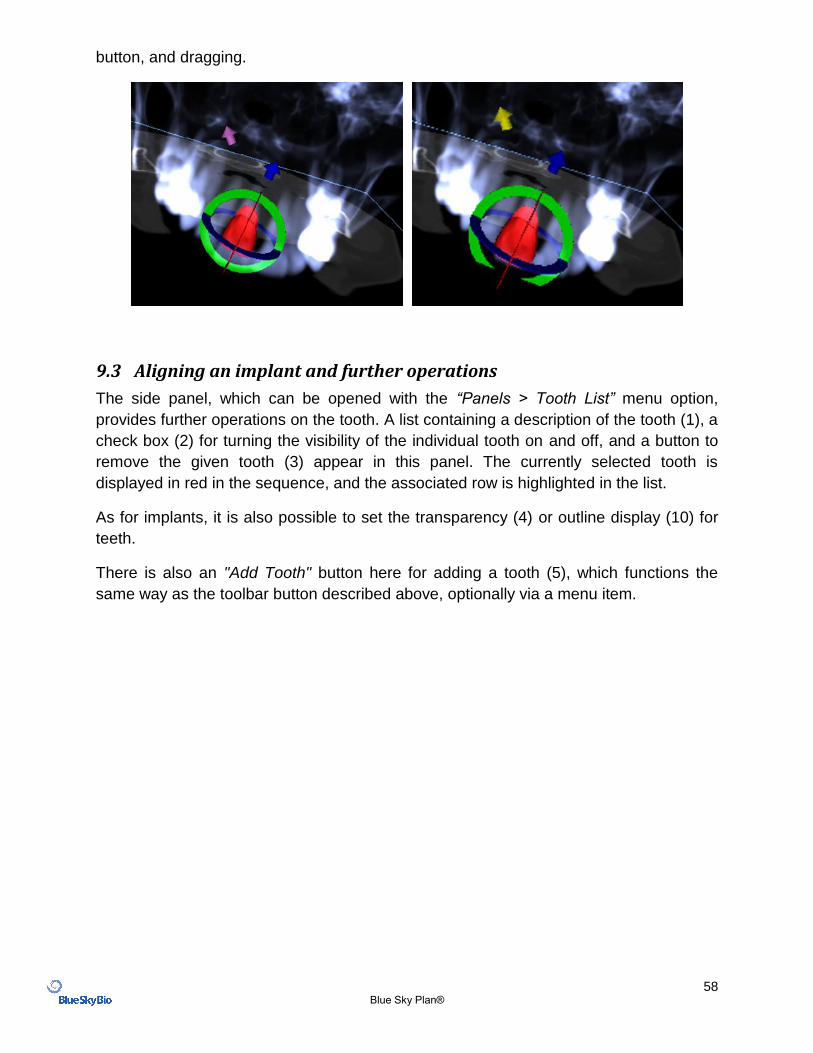
In the 3D view, the tooth can be dragged not only in the plane of the view but also along
the axis of the tooth. As in the other views, it is necessary to move the cursor onto the
tooth and display the draggers. The blue arrows above and below the tooth serve to
shift it along the axis. We change the position of the tooth by moving the cursor to the
arrow, clicking the left mouse button, and dragging. As for implants, three differently
colored circles appear in the 3D view for rotating the tooth around the corresponding
axes of the local coordinate system.
In addition to the position and rotation, the size of the crown can also be modified in the
3D view. The purple arrow displayed along the axis of the tooth serves to change the
size. We change the size of the tooth by moving the cursor to it, clicking the left mouse
58 Blue Sky Plan®
button, and dragging.
9.3 Aligning an implant and further operations
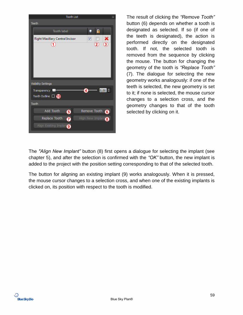
The side panel, which can be opened with the “Panels > Tooth List” menu option,
provides further operations on the tooth. A list containing a description of the tooth (1), a
check box (2) for turning the visibility of the individual tooth on and off, and a button to
remove the given tooth (3) appear in this panel. The currently selected tooth is
displayed in red in the sequence, and the associated row is highlighted in the list.
As for implants, it is also possible to set the transparency (4) or outline display (10) for
teeth.
There is also an "Add Tooth" button here for adding a tooth (5), which functions the
same way as the toolbar button described above, optionally via a menu item.
59 Blue Sky Plan®
The result of clicking the “Remove Tooth”
button (6) depends on whether a tooth is
designated as selected. If so (if one of
the teeth is designated), the action is
performed directly on the designated
tooth. If not, the selected tooth is
removed from the sequence by clicking
the mouse. The button for changing the
geometry of the tooth is “Replace Tooth”
(7). The dialogue for selecting the new
geometry works analogously: if one of the
teeth is selected, the new geometry is set
to it; if none is selected, the mouse cursor
changes to a selection cross, and the
geometry changes to that of the tooth
selected by clicking on it.
The "Align New Implant” button (8) first opens a dialogue for selecting the implant (see
chapter 5), and after the selection is confirmed with the “OK” button, the new implant is
added to the project with the position setting corresponding to that of the selected tooth.
The button for aligning an existing implant (9) works analogously. When it is pressed,
the mouse cursor changes to a selection cross, and when one of the existing implants is
clicked on, its position with respect to the tooth is modified.
60 Blue Sky Plan®
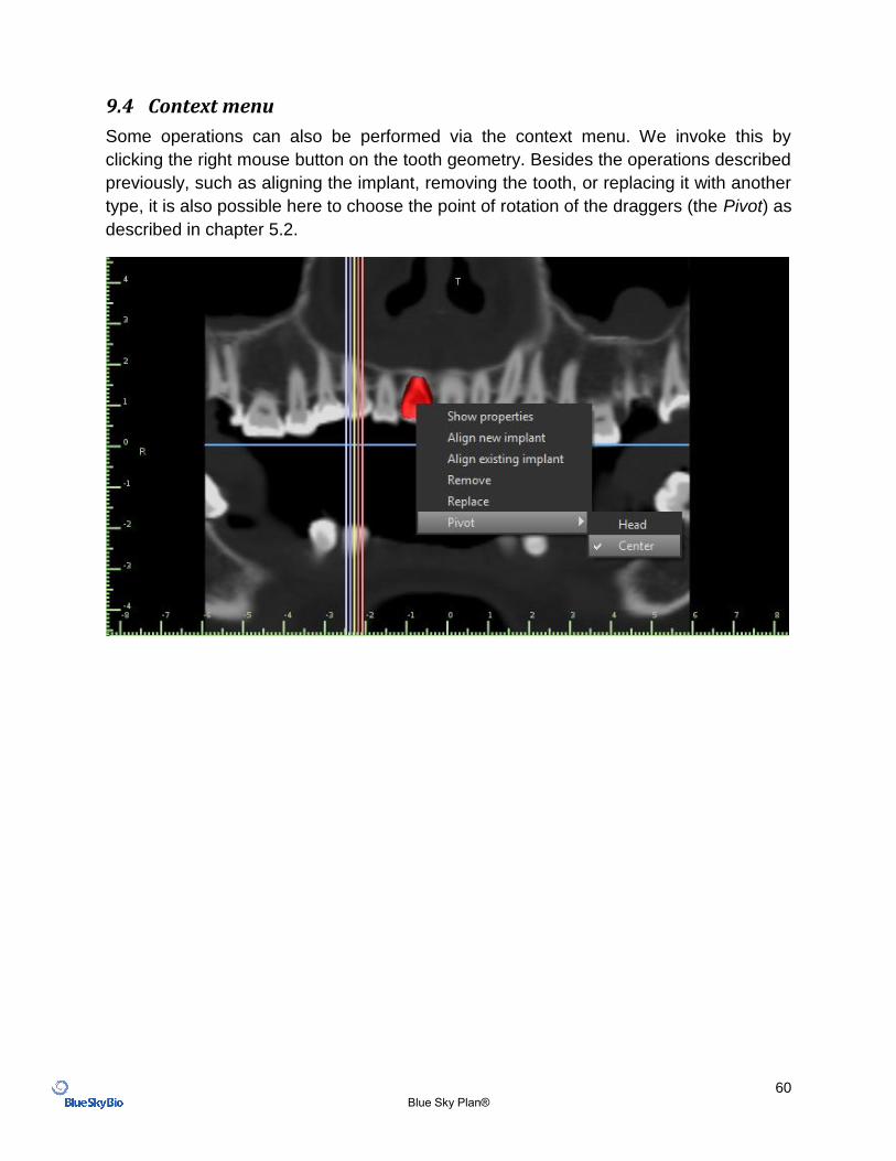
9.4 Context menu
Some operations can also be performed via the context menu. We invoke this by
clicking the right mouse button on the tooth geometry. Besides the operations described
previously, such as aligning the implant, removing the tooth, or replacing it with another
type, it is also possible here to choose the point of rotation of the draggers (the Pivot) as
described in chapter 5.2.
61 Blue Sky Plan®
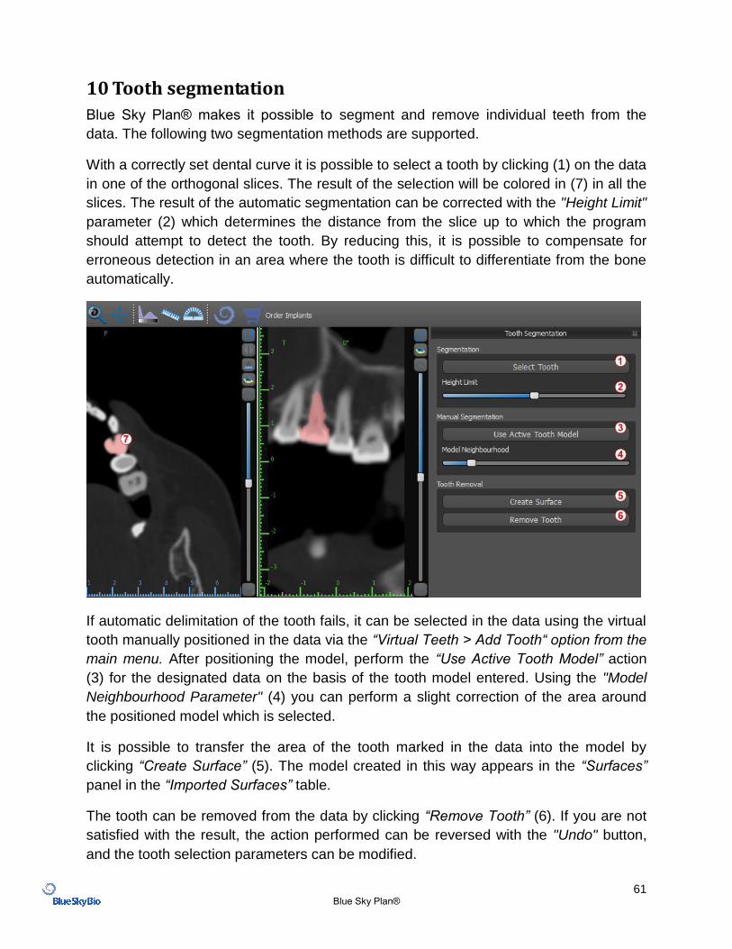
10 Tooth segmentation
Blue Sky Plan® makes it possible to segment and remove individual teeth from the
data. The following two segmentation methods are supported.
With a correctly set dental curve it is possible to select a tooth by clicking (1) on the data
in one of the orthogonal slices. The result of the selection will be colored in (7) in all the
slices. The result of the automatic segmentation can be corrected with the "Height Limit"
parameter (2) which determines the distance from the slice up to which the program
should attempt to detect the tooth. By reducing this, it is possible to compensate for
erroneous detection in an area where the tooth is difficult to differentiate from the bone
automatically.
If automatic delimitation of the tooth fails, it can be selected in the data using the virtual
tooth manually positioned in the data via the “Virtual Teeth > Add Tooth“ option from the
main menu. After positioning the model, perform the “Use Active Tooth Model” action
(3) for the designated data on the basis of the tooth model entered. Using the "Model
Neighbourhood Parameter" (4) you can perform a slight correction of the area around
the positioned model which is selected.
It is possible to transfer the area of the tooth marked in the data into the model by
clicking “Create Surface” (5). The model created in this way appears in the “Surfaces”
panel in the “Imported Surfaces” table.
The tooth can be removed from the data by clicking “Remove Tooth” (6). If you are not
satisfied with the result, the action performed can be reversed with the "Undo" button,
and the tooth selection parameters can be modified.
62 Blue Sky Plan®
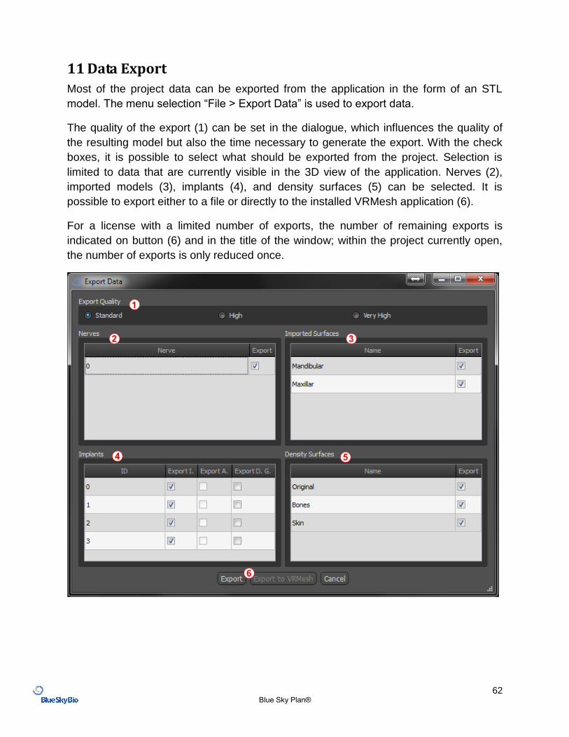
11 Data Export
Most of the project data can be exported from the application in the form of an STL
model. The menu selection “File > Export Data” is used to export data.
The quality of the export (1) can be set in the dialogue, which influences the quality of
the resulting model but also the time necessary to generate the export. With the check
boxes, it is possible to select what should be exported from the project. Selection is
limited to data that are currently visible in the 3D view of the application. Nerves (2),
imported models (3), implants (4), and density surfaces (5) can be selected. It is
possible to export either to a file or directly to the installed VRMesh application (6).
For a license with a limited number of exports, the number of remaining exports is
indicated on button (6) and in the title of the window; within the project currently open,
the number of exports is only reduced once.
63 Blue Sky Plan®
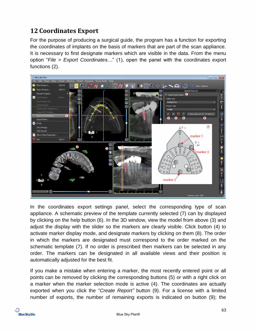
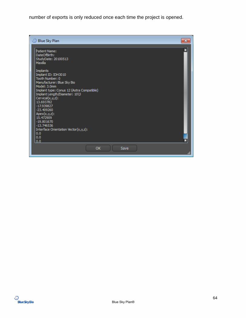
12 Coordinates Export
For the purpose of producing a surgical guide, the program has a function for exporting
the coordinates of implants on the basis of markers that are part of the scan appliance.
It is necessary to first designate markers which are visible in the data. From the menu
option “File > Export Coordinates…” (1), open the panel with the coordinates export
functions (2).
In the coordinates export settings panel, select the corresponding type of scan
appliance. A schematic preview of the template currently selected (7) can by displayed
by clicking on the help button (6). In the 3D window, view the model from above (3) and
adjust the display with the slider so the markers are clearly visible. Click button (4) to
activate marker display mode, and designate markers by clicking on them (8). The order
in which the markers are designated must correspond to the order marked on the
schematic template (7). If no order is prescribed then markers can be selected in any
order. The markers can be designated in all available views and their position is
automatically adjusted for the best fit.
If you make a mistake when entering a marker, the most recently entered point or all
points can be removed by clicking the corresponding buttons (5) or with a right click on
a marker when the marker selection mode is active (4). The coordinates are actually
exported when you click the “Create Report” button (9). For a license with a limited
number of exports, the number of remaining exports is indicated on button (9); the
64 Blue Sky Plan®
number of exports is only reduced once each time the project is opened.
65 Blue Sky Plan®
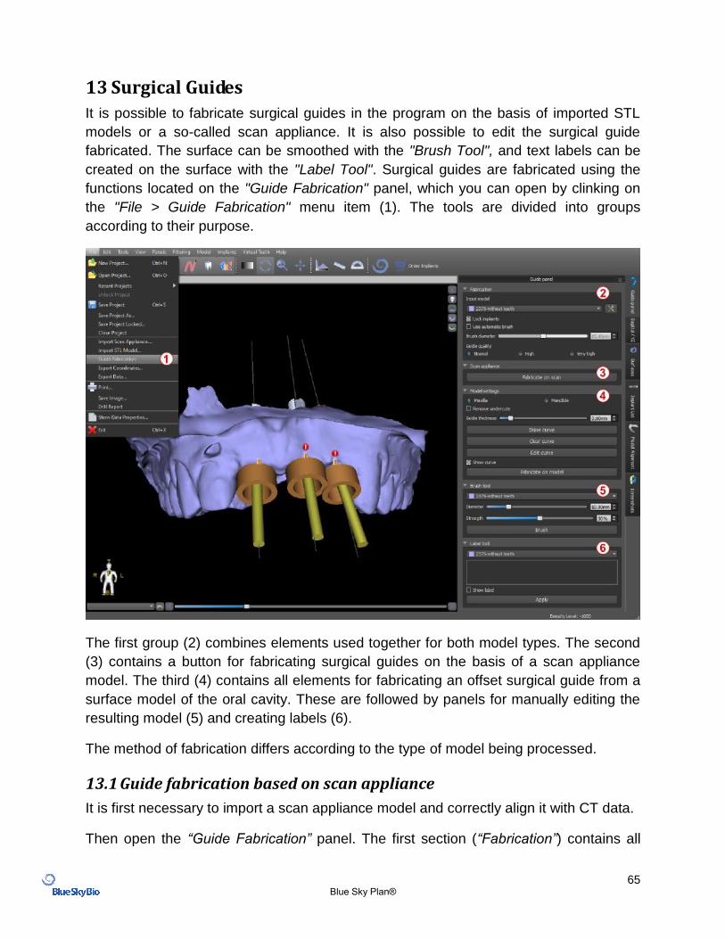
13 Surgical Guides
It is possible to fabricate surgical guides in the program on the basis of imported STL
models or a so-called scan appliance. It is also possible to edit the surgical guide
fabricated. The surface can be smoothed with the "Brush Tool", and text labels can be
created on the surface with the "Label Tool". Surgical guides are fabricated using the
functions located on the "Guide Fabrication" panel, which you can open by clinking on
the "File > Guide Fabrication" menu item (1). The tools are divided into groups
according to their purpose.
The first group (2) combines elements used together for both model types. The second
(3) contains a button for fabricating surgical guides on the basis of a scan appliance
model. The third (4) contains all elements for fabricating an offset surgical guide from a
surface model of the oral cavity. These are followed by panels for manually editing the
resulting model (5) and creating labels (6).
The method of fabrication differs according to the type of model being processed.
13.1 Guide fabrication based on scan appliance
It is first necessary to import a scan appliance model and correctly align it with CT data.
Then open the “Guide Fabrication” panel. The first section (“Fabrication”) contains all
66 Blue Sky Plan®
common settings for fabricating a surgical guide. The combo box (1) is used to select
the input model.
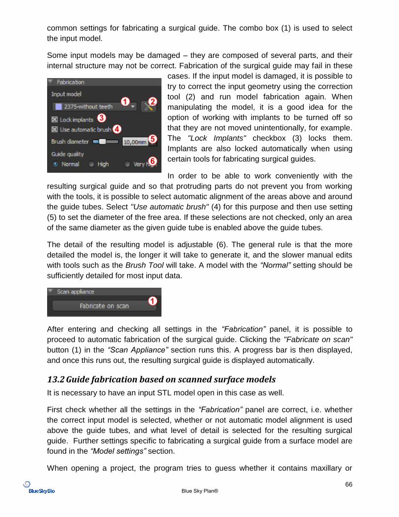
Some input models may be damaged – they are composed of several parts, and their
internal structure may not be correct. Fabrication of the surgical guide may fail in these
cases. If the input model is damaged, it is possible to
try to correct the input geometry using the correction
tool (2) and run model fabrication again. When
manipulating the model, it is a good idea for the
option of working with implants to be turned off so
that they are not moved unintentionally, for example.
The "Lock Implants" checkbox (3) locks them.
Implants are also locked automatically when using
certain tools for fabricating surgical guides.
In order to be able to work conveniently with the
resulting surgical guide and so that protruding parts do not prevent you from working
with the tools, it is possible to select automatic alignment of the areas above and around
the guide tubes. Select "Use automatic brush" (4) for this purpose and then use setting
(5) to set the diameter of the free area. If these selections are not checked, only an area
of the same diameter as the given guide tube is enabled above the guide tubes.
The detail of the resulting model is adjustable (6). The general rule is that the more
detailed the model is, the longer it will take to generate it, and the slower manual edits
with tools such as the Brush Tool will take. A model with the “Normal” setting should be
sufficiently detailed for most input data.
After entering and checking all settings in the “Fabrication” panel, it is possible to
proceed to automatic fabrication of the surgical guide. Clicking the "Fabricate on scan"
button (1) in the “Scan Appliance” section runs this. A progress bar is then displayed,
and once this runs out, the resulting surgical guide is displayed automatically.
13.2 Guide fabrication based on scanned surface models
It is necessary to have an input STL model open in this case as well.
First check whether all the settings in the “Fabrication” panel are correct, i.e. whether
the correct input model is selected, whether or not automatic model alignment is used
above the guide tubes, and what level of detail is selected for the resulting surgical
guide. Further settings specific to fabricating a surgical guide from a surface model are
found in the “Model settings” section.
When opening a project, the program tries to guess whether it contains maxillary or
67 Blue Sky Plan®
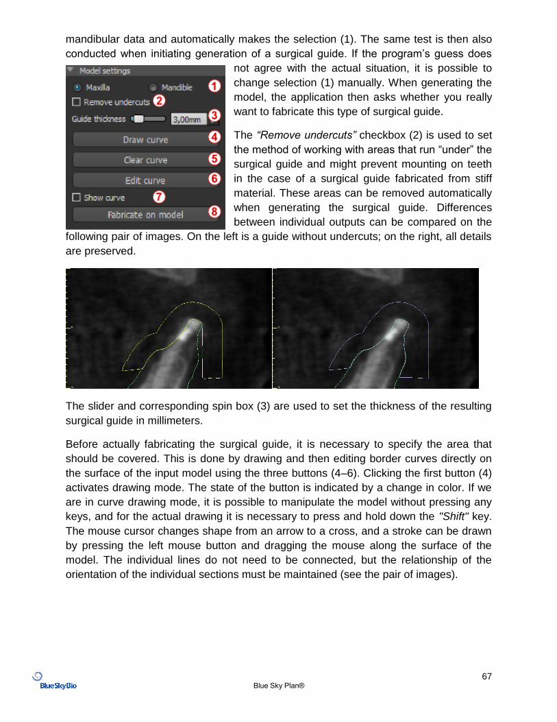
mandibular data and automatically makes the selection (1). The same test is then also
conducted when initiating generation of a surgical guide. If the program’s guess does
not agree with the actual situation, it is possible to
change selection (1) manually. When generating the
model, the application then asks whether you really
want to fabricate this type of surgical guide.
The “Remove undercuts” checkbox (2) is used to set
the method of working with areas that run “under” the
surgical guide and might prevent mounting on teeth
in the case of a surgical guide fabricated from stiff
material. These areas can be removed automatically
when generating the surgical guide. Differences
between individual outputs can be compared on the
following pair of images. On the left is a guide without undercuts; on the right, all details
are preserved.
The slider and corresponding spin box (3) are used to set the thickness of the resulting
surgical guide in millimeters.
Before actually fabricating the surgical guide, it is necessary to specify the area that
should be covered. This is done by drawing and then editing border curves directly on
the surface of the input model using the three buttons (4–6). Clicking the first button (4)
activates drawing mode. The state of the button is indicated by a change in color. If we
are in curve drawing mode, it is possible to manipulate the model without pressing any
keys, and for the actual drawing it is necessary to press and hold down the "Shift" key.
The mouse cursor changes shape from an arrow to a cross, and a stroke can be drawn
by pressing the left mouse button and dragging the mouse along the surface of the
model. The individual lines do not need to be connected, but the relationship of the
orientation of the individual sections must be maintained (see the pair of images).
68 Blue Sky Plan®
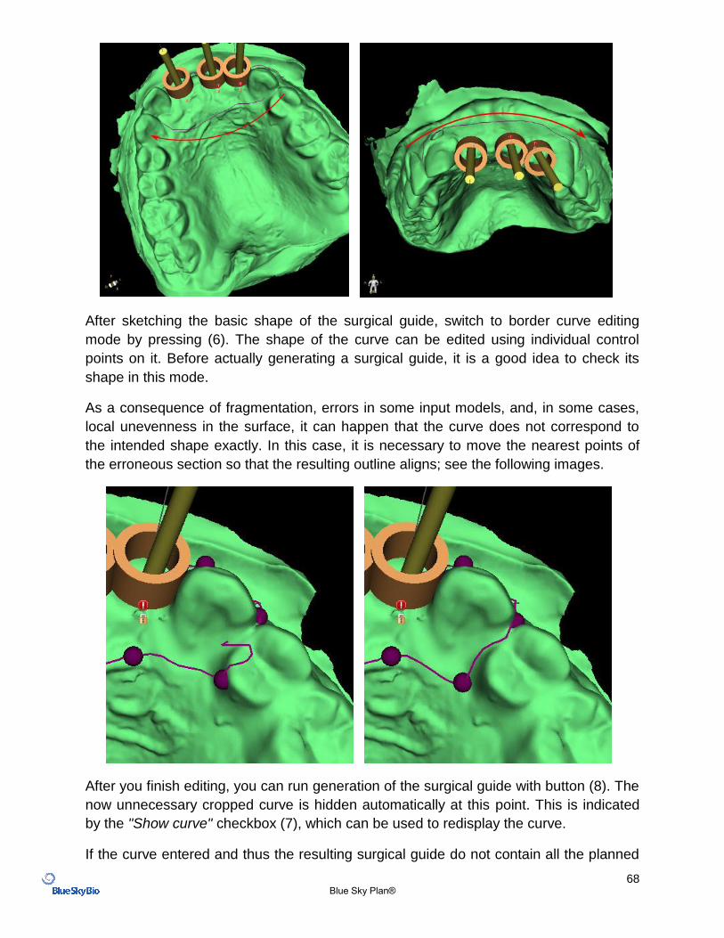
After sketching the basic shape of the surgical guide, switch to border curve editing
mode by pressing (6). The shape of the curve can be edited using individual control
points on it. Before actually generating a surgical guide, it is a good idea to check its
shape in this mode.
As a consequence of fragmentation, errors in some input models, and, in some cases,
local unevenness in the surface, it can happen that the curve does not correspond to
the intended shape exactly. In this case, it is necessary to move the nearest points of
the erroneous section so that the resulting outline aligns; see the following images.
After you finish editing, you can run generation of the surgical guide with button (8). The
now unnecessary cropped curve is hidden automatically at this point. This is indicated
by the "Show curve" checkbox (7), which can be used to redisplay the curve.
If the curve entered and thus the resulting surgical guide do not contain all the planned
69 Blue Sky Plan®
implants, the user is notified and has the option of halting generation.
Once it is completed, the model surgical guide fabricated is displayed and also added to
the list on the "Surfaces" panel, where its parameters can be changed in the standard
way.
The surgical guide can be regenerated with edited parameters and the same curve; the
curve is merely hidden and can be displayed with selection (7), edited again, and used
to create a modified model.
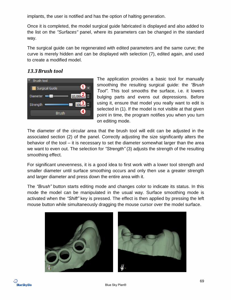
13.3 Brush tool
The application provides a basic tool for manually
smoothing the resulting surgical guide: the “Brush
Tool”. This tool smooths the surface, i.e. it lowers
bulging parts and evens out depressions. Before
using it, ensure that model you really want to edit is
selected in (1). If the model is not visible at that given
point in time, the program notifies you when you turn
on editing mode.
The diameter of the circular area that the brush tool will edit can be adjusted in the
associated section (2) of the panel. Correctly adjusting the size significantly alters the
behavior of the tool – it is necessary to set the diameter somewhat larger than the area
we want to even out. The selection for “Strength” (3) adjusts the strength of the resulting
smoothing effect.
For significant unevenness, it is a good idea to first work with a lower tool strength and
smaller diameter until surface smoothing occurs and only then use a greater strength
and larger diameter and press down the entire area with it.
The “Brush” button starts editing mode and changes color to indicate its status. In this
mode the model can be manipulated in the usual way. Surface smoothing mode is
activated when the “Shift” key is pressed. The effect is then applied by pressing the left
mouse button while simultaneously dragging the mouse cursor over the model surface.
70 Blue Sky Plan®
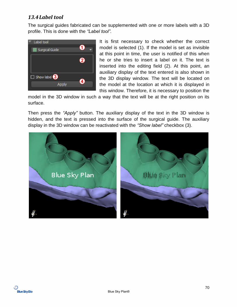
13.4 Label tool
The surgical guides fabricated can be supplemented with one or more labels with a 3D
profile. This is done with the “Label tool”.
It is first necessary to check whether the correct
model is selected (1). If the model is set as invisible
at this point in time, the user is notified of this when
he or she tries to insert a label on it. The text is
inserted into the editing field (2). At this point, an
auxiliary display of the text entered is also shown in
the 3D display window. The text will be located on
the model at the location at which it is displayed in
this window. Therefore, it is necessary to position the
model in the 3D window in such a way that the text will be at the right position on its
surface.
Then press the “Apply” button. The auxiliary display of the text in the 3D window is
hidden, and the text is pressed into the surface of the surgical guide. The auxiliary
display in the 3D window can be reactivated with the “Show label” checkbox (3).
71 Blue Sky Plan®
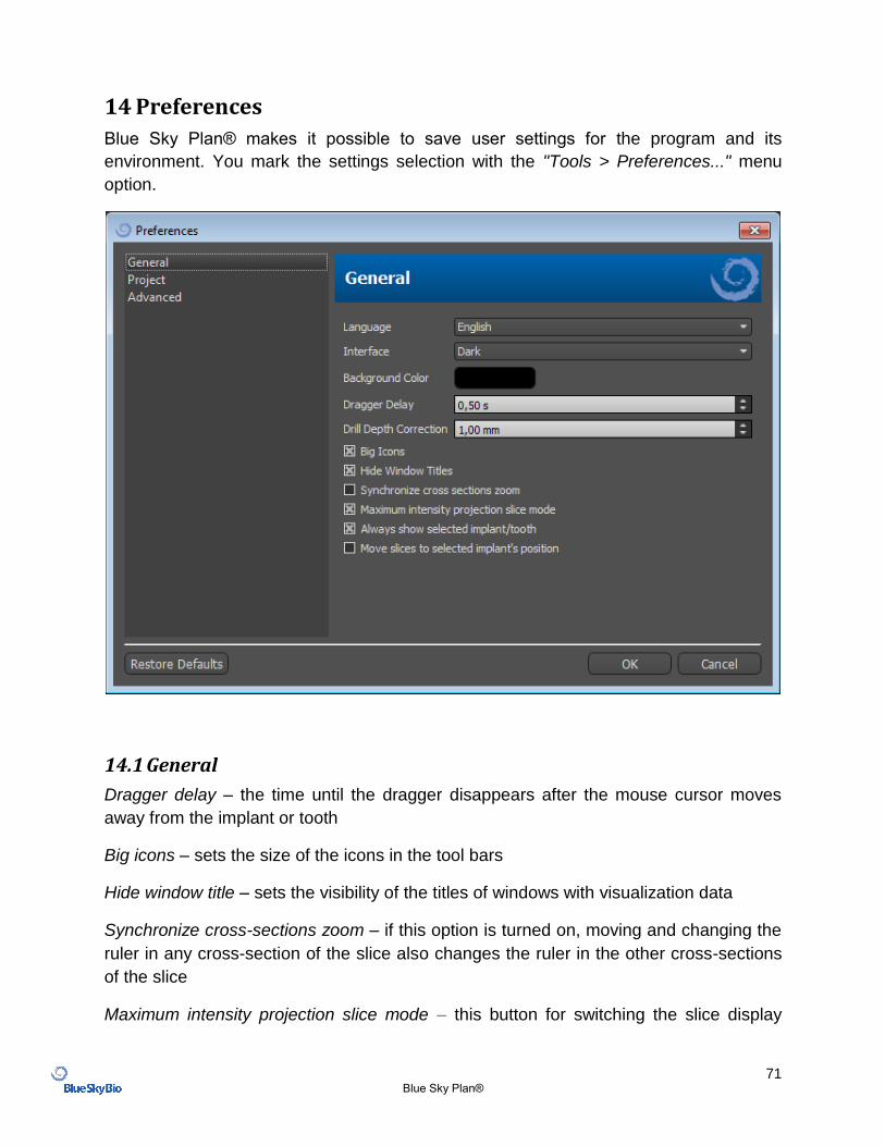
14 Preferences
Blue Sky Plan® makes it possible to save user settings for the program and its
environment. You mark the settings selection with the "Tools > Preferences..." menu
option.
14.1 General
Dragger delay – the time until the dragger disappears after the mouse cursor moves
away from the implant or tooth
Big icons – sets the size of the icons in the tool bars
Hide window title – sets the visibility of the titles of windows with visualization data
Synchronize cross-sections zoom – if this option is turned on, moving and changing the
ruler in any cross-section of the slice also changes the ruler in the other cross-sections
of the slice
Maximum intensity projection slice mode – this button for switching the slice display
72 Blue Sky Plan®
mode offers two variants: MIP (maximum intensity projection) and X-ray.
Always show selected implant/tooth – ensures visibility of the active implant when
implants/teeth are fully transparent
Drill Depth Correction – a correction factor for the distance of the Drill Guide from the
implant when exporting.
Move slices to selected implant’s position – clicking on the implant sets the positions of
the orthogonal and normal slices on the selected implant.
Advanced gestures in Leap viewing mode – enables advanced scene manipulation
gestures in Leap viewing mode. A Leap controller is required.
Zoom with circle gestures – toggle the effect of the circle gesture between slider control
and zoom control.
14.2 Project
Autosave project – automatically saves the project at the time interval entered
14.3 Advanced
Rendering mode – the multi-threaded mode provides somewhat better display
performance but may lead to program instability with inappropriate graphics card
drivers.
Logging – allows information about the execution of the program to be stored in a log
The log can be displayed by clicking the "Show Log" button, and its content can make it
easier for the program manufacturer to solve problems that arise when running the
program on specific hardware configurations.
Automatically check for updates – every day when it first starts up, the application
checks whether you are using the newest release and, if not, offers to install the update
for you.
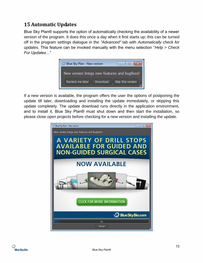
73 Blue Sky Plan®
15 Automatic Updates
Blue Sky Plan® supports the option of automatically checking the availability of a newer
version of the program. It does this once a day when it first starts up; this can be turned
off in the program settings dialogue in the “Advanced” tab with Automatically check for
updates. This feature can be invoked manually with the menu selection “Help > Check
For Updates…”
If a new version is available, the program offers the user the options of postponing the
update till later, downloading and installing the update immediately, or skipping this
update completely. The update download runs directly in the application environment,
and to install it, Blue Sky Plan® must shut down and then start the installation, so
please close open projects before checking for a new version and installing the update.