Embed Size (px)
Citation preview

Block I/O Modules Manual
Version 3.2
G & L Motion Control Inc.

NOTE
Progress is an on-going commitment at G & L Motion Control Inc. We continually strive to offer the most advanced products in the industry; therefore, information in this document is subject to change without notice. The illustrations and specifications are not binding in detail. G & L Motion Control Inc. shall not be liable for any technical or editorial omissions occurring in this document, nor for any consequential or incidental damages resulting from the use of this document.
DO NOT ATTEMPT to use any G & L Motion Control Inc. product until the use of such product is completely understood. It is the responsibility of the user to make certain proper operation practices are understood. G & L Motion Control Inc. products should be used only by qualified personnel and for the express purpose for which said products were designed.
Should information not covered in this document be required, contact the Customer Service Department, G & L Motion Control Inc., 672 South Military Road, P.O. Box 1960, Fond du Lac, WI 54936-1960. G & L Motion Control Inc. can be reached by telephone at (920) 921–7100 or at (800)558-4808 in the United States or by e-mail at [email protected].
Release 1705
Part Number M.1302.8339
© 2005 G & L Motion Control Inc.
Windows 95, 98, NT, Microsoft, and MS-DOS are registered trademarks of Microsoft Corporation.Pentium and PentiumPro are trademarks of Intel Corporation.PiC900, PiCPro, MMC, MMC for PC, PiCServoPro, PiCTune, PiCProfile, LDO Merge, PiCMicroTerm and PiC Programming Pendant are trademarks of G & L Motion Control Inc.

Table of Contents: Block I/O Modules Manual
Table of Contents: Block I/O Modules Manual TOC-1
TOC-1
1 Safety Precautions.................................................................................................... 1-11.1 System Safety ................................................................................................... 1-1
1.1.1 User Responsibility .............................................................................. 1-11.1.2 Safety Instructions................................................................................ 1-2
1.2 Safety Signs ...................................................................................................... 1-21.3 Warning Labels................................................................................................. 1-31.4 Safety First ........................................................................................................ 1-41.5 Safety Inspection............................................................................................... 1-4
1.5.1 Before Starting Operations................................................................... 1-41.6 After Shutdown................................................................................................. 1-41.7 Operating Safely ............................................................................................... 1-51.8 Electrical Service & Maintenance Safety ......................................................... 1-61.9 Safe Cleaning Practices .................................................................................... 1-7
2 Guide to Using Block I/O ........................................................................................ 2-12.1 Attaching a Block I/O Module to the DIN Rail................................................ 2-12.2 Safety Concerns ................................................................................................ 2-22.3 Wiring Guidelines............................................................................................. 2-32.4 Troubleshooting ............................................................................................... 2-6
2.4.1 Troubleshooting Table ......................................................................... 2-62.4.2 Troubleshooting Communication Problems - LEDs and Blink Codes 2-7
3 Block Output 24V DC Source Module (16 Points) ............................................... 3-13.1 Introduction....................................................................................................... 3-13.2 Connections ...................................................................................................... 3-2
3.2.1 Communications Connections.............................................................. 3-43.2.1.1 LEDs ................................................................................... 3-4
3.2.2 Protecting from an Inductive Load....................................................... 3-53.3 Theory of Operation.......................................................................................... 3-63.4 Specification Table .......................................................................................... 3-7
4 Block Input 24V DC Module (16 points) ............................................................... 4-14.1 Introduction....................................................................................................... 4-14.2 Connections ...................................................................................................... 4-2
4.2.1 Communications Connections.............................................................. 4-44.2.1.1 LEDs ................................................................................... 4-4
4.3 Theory of Operation.......................................................................................... 4-54.4 Specification Table ........................................................................................... 4-7
5 Block 24V DC 8 In/8 Out Module .......................................................................... 5-15.1 Introduction....................................................................................................... 5-15.2 Connections ...................................................................................................... 5-2
5.2.1 Communications Connections.............................................................. 5-55.2.1.1 LEDs ................................................................................... 5-5
G & L Motion Control Inc. Block I/O Modules Manual TOC-1

5.2.2 Protecting from an Inductive Load....................................................... 5-65.3 Theory of Operation.......................................................................................... 5-7
5.3.1 Outputs ................................................................................................. 5-75.3.2 Inputs.................................................................................................... 5-7
5.4 Specification Table ........................................................................................... 5-106 Block Output 120V AC Module (8 points) ............................................................ 6-1
6.1 Introduction....................................................................................................... 6-16.2 Connections ...................................................................................................... 6-2
6.2.1 Fusing ................................................................................................... 6-36.2.1.1 Fuse Monitor....................................................................... 6-3
6.2.2 Communications Connections.............................................................. 6-46.2.2.1 LEDs ................................................................................... 6-4
6.2.3 Protecting from an Inductive Load....................................................... 6-56.3 Theory of Operation.......................................................................................... 6-56.4 Specification Table ........................................................................................... 6-6
7 Block Relay Module (8 points)................................................................................ 7-17.1 Introduction....................................................................................................... 7-17.2 Connections ...................................................................................................... 7-2
7.2.1 Normally Open Contact Form C Type................................................. 7-37.2.2 Normally Closed Contact Form C Type .............................................. 7-37.2.3 Normally Open Contact Form A Type................................................. 7-47.2.4 Contact Noise Suppression................................................................... 7-57.2.5 Communications Connections.............................................................. 7-6
7.2.5.1 LEDs ................................................................................... 7-67.3 Theory of Operation.......................................................................................... 7-77.4 Specification Table ........................................................................................... 7-9
8 Block Input 120V AC Module (8 points) ............................................................... 8-18.1 Introduction....................................................................................................... 8-18.2 Connections ...................................................................................................... 8-2
8.2.1 Communications Connections.............................................................. 8-48.2.1.1 LEDs ................................................................................... 8-4
8.3 Theory of Operation.......................................................................................... 8-58.4 Specification Table ........................................................................................... 8-7
9 Block Input Resolver Module (6 channel) ............................................................. 9-19.1 Introduction....................................................................................................... 9-19.2 Connections ...................................................................................................... 9-2
9.2.1 Adding an External Potentiometer ....................................................... 9-59.2.2 Communications Connections.............................................................. 9-6
9.2.2.1 LEDs ................................................................................... 9-69.3 Resolvers........................................................................................................... 9-79.4 Theory of Operation.......................................................................................... 9-79.5 Specification Table ........................................................................................... 9-8
10 Block Output Stepper/Input Encoder/Input 24V DC Module (2/2/2 Channel)............................................................................. 10-1
10.1 Introduction....................................................................................................... 10-110.1.1 Output Stepper...................................................................................... 10-210.1.2 Input Encoder ....................................................................................... 10-2
TOC-2 Block I/O Modules Manual G & L Motion Control Inc.
10.1.3 Input 24V DC....................................................................................... 10-210.2 Connections ...................................................................................................... 10-3
10.2.1 Stepper Connections............................................................................. 10-310.2.2 Connecting the Block Module to Stepper Drives................................. 10-5
10.2.2.1 Opto-Coupler Drive Inputs ................................................. 10-610.2.2.2 Opto-Coupler with Common Source DriveInputs ............................................................................................10-710.2.2.3 Single-Ended Drive Inputs.................................................. 10-810.2.2.4 Differential Drive Inputs..................................................... 10-10
10.2.3 Block Module Encoder Connections.................................................... 10-1210.2.3.1 Encoder Drivers .................................................................. 10-14
10.2.4 Block Module DC Input Connections.................................................. 10-1510.2.5 Power Connections............................................................................... 10-1510.2.6 Communications Connections.............................................................. 10-16
10.2.6.1 LEDs ................................................................................... 10-1610.3 Theory of Operation.......................................................................................... 10-17
10.3.1 Stepper Theory of Operation................................................................ 10-1710.3.2 Block Module Encoder Theory of Operation....................................... 10-18
10.3.2.1 Incremental Encoders ......................................................... 10-1810.3.3 DC Input Theory of Operation ............................................................. 10-20
10.4 Specification Table .......................................................................................... 10-2211 Block Input Analog Module (4 Channel)............................................................... 11-1
11.1 Introduction....................................................................................................... 11-111.2 Connections ...................................................................................................... 11-2
11.2.1 Communications Connections.............................................................. 11-711.2.1.1 LEDs ................................................................................... 11-7
11.3 Theory of Operation.......................................................................................... 11-811.4 Specification Table .......................................................................................... 11-9
12 Block Output 4-20mA Module (4 Channel) .......................................................... 12-112.1 Introduction....................................................................................................... 12-112.2 Connections ...................................................................................................... 12-2
12.2.1 Communications Connections.............................................................. 12-412.2.1.1 LEDs ................................................................................... 12-4
12.3 Theory of Operation.......................................................................................... 12-612.4 Specification Table ........................................................................................... 12-7
13 Block Output +10V DC Module (4 Channel) ........................................................ 13-113.1 Introduction....................................................................................................... 13-113.2 Connections ...................................................................................................... 13-2
13.2.1 Communications Connections.............................................................. 13-313.2.1.1 LEDs ................................................................................... 13-3
13.2.2 Analog Output Receiving Devices....................................................... 13-413.3 Theory of Operation.......................................................................................... 13-513.4 Specification Table ........................................................................................... 13-6
14 Block Input 24V DC Module/J (16 points) ............................................................ 14-114.1 Introduction....................................................................................................... 14-114.2 Connections ...................................................................................................... 14-2
14.2.1 Communications Connections.............................................................. 14-5
G & L Motion Control Inc. Block I/O Modules Manual TOC-3
14.2.1.1 LEDs ................................................................................... 14-514.3 Theory of Operation.......................................................................................... 14-614.4 Specification Table ........................................................................................... 14-8
15 Block 24V DC 8 In/8 Out Module/J ....................................................................... 15-115.1 Introduction....................................................................................................... 15-115.2 Connections ...................................................................................................... 15-2
15.2.1 Communications Connections.............................................................. 15-515.2.1.1 LEDs ................................................................................... 15-5
15.2.2 Protecting from an Inductive Load....................................................... 15-615.3 Theory of Operation.......................................................................................... 15-7
15.3.1 Outputs ................................................................................................. 15-715.3.2 Inputs.................................................................................................... 15-7
15.4 Specification Table ........................................................................................... 15-1016 Block Input/Output Analog Module (4 In 4 Out) ................................................. 16-1
16.1 Introduction....................................................................................................... 16-116.2 Connections ...................................................................................................... 16-2
16.2.1 Analog Output Receiving Devices....................................................... 16-716.2.2 Communications Connections.............................................................. 16-8
16.2.2.1 LEDs ................................................................................... 16-816.3 Theory of Operation.......................................................................................... 16-916.4 Specification Table .......................................................................................... 16-10
17 Block Input J-K Thermocouple Module(8 channel) ............................................................................................................................... 17-1
17.1 Introduction....................................................................................................... 17-117.2 Connections ...................................................................................................... 17-2
17.2.1 Communications Connections.............................................................. 17-517.2.1.1 LEDs ................................................................................... 17-5
17.3 Theory of Operation.......................................................................................... 17-617.4 Thermocouple Precautions ............................................................................... 17-617.5 Specification Table ........................................................................................... 17-7
18 5-Axis Integrated Stepper Module ......................................................................... 18-118.1 Introduction ..................................................................................................... 18-2
18.1.1 Output Stepper ..................................................................................... 18-218.1.2 Input Encoder ...................................................................................... 18-218.1.3 Dimensions........................................................................................... 18-318.1.4 LEDs ................................................................................................ 18-4
18.2 Connections ...................................................................................................... 18-518.2.1 Pin Assignments ............................................................................. 18-518.2.2 FAISM to Stepper Motor Connections ................................................ 18-618.2.3 FAISM Encoder Connections .............................................................. 18-718.2.4 FAISM DC Input Connections............................................................. 18-7
18.3 Theory of Operation.......................................................................................... 18-818.3.1 FAISM Theory of Operation ............................................................... 18-818.3.2 FAISM Encoder Theory of Operation ................................................ 18-1018.3.3 DC Input Theory of Operation ............................................................ 18-10
18.4 Specification Table ....................................................................................... 18-11
TOC-4 Block I/O Modules Manual G & L Motion Control Inc.

INDEX IND-1
G & L Motion Control Inc. Block I/O Modules Manual TOC-5

TOC-6 Block I/O Modules Manual G & L Motion Control Inc.

Safety Precautions
1 Safety Precautions
READ AND UNDERSTAND THIS SECTION IN ITS ENTIRETY BEFORE UNDERTAKING INSTALLATION OR
ADJUSTMENT OF BLOCK I/O MODULES
The advice contained in this section will help users to operate and maintain the equipment in a safe manner at all times.
PLEASE REMEMBER THAT SAFETY IS EVERYONE'S RESPONSIBILITY
1.1 System SafetyThe basic rules of safety set forth in this section are intended as a guide for the safe operation of equipment. This general safety information, along with explicit service, maintenance and operational materials, make up the complete instruction set. All personnel who operate, service or are involved with this equipment in any way should become totally familiar with this information prior to operating.
1.1.1 User Responsibility
It is the responsibility of the user to ensure that the procedures set forth here are followed and, should any major deviation or change in use from the original specifications be required, appropriate procedures should be established for the continued safe operation of the system. It is strongly recommended that you contact your OEM to ensure that the system can be safely converted for its new use and continue to operate in a safe manner.
G & L Motion Control Inc. Block I/O Modules Manual 1-1

Safety Precautions
1.1.2 Safety Instructions
1. Do not operate your equipment with safety devices bypassed or doors removed.
2. Only qualified personnel should operate the equipment.
3. Never perform service or maintenance while automatic con-trol sequences are in operation.
4. To avoid shock or serious injury, only qualified personnel should perform maintenance on the system.
5.
6. GROUNDING (Protective Earth)The equipment must be grounded (connected to the protective earth connection) according to OEM recommendations and to the latest local regulations for electrical safety. The grounding (protective earth) conductor must not be interrupted inside or outside the equipment enclosures. The wire used for equip-ment grounding (connection to protective earth) should be green with a yellow stripe.
7. If there is any doubt at all as to the safety of the equipment, you should set the main power switch to OFF and contact your OEM for advice.
1.2 Safety SignsThe purpose of a system of safety signs is to draw attention to objects and situations which could affect personal or plant safety. It should be noted that the use of safety signs does not replace the need for appropriate accident prevention measures. Always read and follow the instructions based upon the level of hazard or potential danger.
ATTENTION- DANGER TO LIFE
Do not touch the main power supply fuses or anycomponents internal to the power modules while themain power supply switch is ON. Note that when themain power switch is OFF, the incoming supply ca-ble may be live.
1-2 Block I/O Modules Manual G & L Motion Control Inc.

Safety Precautions
1.3 Warning LabelsHazard warning
When you see this safety sign on a system, it gives a warning of a hazard or possibility of a hazard existing. The type of warning is given by the pictorial representation on the sign plus text if used.
The safety color is black on a yellow background with a black symbol. To ignore such a caution could lead to severe injury or death arising from an unsafe practice. If voltage levels are included in the text they must indicate the maximum level of the hazard in normal or fault condition.
Danger, Warning, or Caution warning
Hot Surface warning
Danger Electric Shock Risk
Symbol plus DANGER, WARNING or CAUTION: These notices provide information intended to prevent potential personal injury and equipment damage.
Hot Surface
G & L Motion Control Inc. Block I/O Modules Manual 1-3
Safety Precautions
1.4 Safety FirstG&L Motion Control equipment is designed and manufactured with consideration and care to generally accepted safety standards. However, the proper and safe performance of the equipment depends upon the use of sound and prudent operating, maintenance and servicing procedures by trained personnel under adequate supervision.
For your protection, and the protection of others, learn and always follow these safety rules. Observe warnings on machines and act accordingly. Form safe working habits by reading the rules and abiding by them. Keep these safety rules handy and review them from time to time to refresh your understanding of them.
1.5 Safety Inspection
1.5.1 Before Starting Operations
1. Ensure that all guards and safety devices are installed and operative and all doors which carry warning labels are closed and locked.
2. Ensure that all personnel are clear of those areas indicated as potentially hazardous.
3. Remove (from the operating zone) any materials, tools or other objects that could cause injury to personnel or damage the system.
4. Make sure that the control system is in an operational condi-tion.
5. Make certain that all indicating lights, horns, pressure gauges or other safety devices or indicators are in working order.
1.6 After ShutdownMake certain all controlled equipment in the plant is safe and the associated electrical, pneumatic or hydraulic power is turned off. It is permissible for the control equipment contained in enclosures to remain energized provided this does not conflict with the safety instructions found in this section.
1-4 Block I/O Modules Manual G & L Motion Control Inc.
Safety Precautions
1.7 Operating Safely1. Do not operate the control system until you read and understand the
operating instructions and become thoroughly familiar with the system and the controls.
2. Never operate the control system while a safety device or guard is removed or disconnected
3. Where access to the control system is permitted for manual operation, only those doors which provide that access should be unlocked. They should be locked immediately after the particular operation is com-pleted.
4. Never remove warnings that are displayed on the equipment. Torn or worn labels should be replaced.
5. Do not start the control system until all personnel in the area have been warned.
6. Never sit or stand on anything that might cause you to fall onto the con-trol equipment or its peripheral equipment.
7. Horseplay around the control system and its associated equipment is dangerous and should be prohibited.
8. Know the emergency stop procedure for the system.
9. For maximum protection when carrying out major servicing requiring the system to be powered down, the power source should be locked using a lock for which only you have the key. This prevents anyone from accidentally turning on the power while you are servicing the equipment.
10. Never operate the equipment outside specification limits.
11. Keep alert and observe indicator lights, system messages and warnings that are displayed on the system.
12. Do not operate faulty or damaged equipment. Make certain proper ser-vice and maintenance procedures have been performed.
G & L Motion Control Inc. Block I/O Modules Manual 1-5

Safety Precautions
1.8 Electrical Service & Maintenance Safety1. ALL ELECTRICAL OR ELECTRONIC MAINTENANCE AND
SERVICE SHOULD BE PERFORMED BY TRAINED AND AUTHORIZED PERSONNEL ONLY.
2. It should be assumed at all times that the POWER is ON and all condi-tions treated as live. This practice assures a cautious approach which may prevent accident or injury.
3. To remove power:LOCK THE MAIN SWITCH IN THE OPEN POSITION.USE A LOCK TO WHICH ONLY YOU HAVE THE KEY.
4. Make sure the circuit is safe by using the proper test equipment. Check test equipment regularly
5. Capacitors take time to discharge. Care should be taken in manual dis-charging of capacitors
6. There may be circumstances where troubleshooting on live equipment is required. Under such conditions, special precautions must be taken:
• Make sure your tools and body are clear of the areas of equipment which may be live.
• Extra safety measures should be taken in damp areas.
• Be alert and avoid any outside distractions.
• Make certain another qualified person is in attendance.
7. Before applying power to any equipment, make certain that all per-sonnel are clear of associated equipment.
8. Control panel doors should be unlocked only when checking out elec-trical equipment or wiring. On completion, close and lock panel doors.
9. All covers on junction panels should be fastened closed before leav-ing any job.
10. Never operate any controls while others are performing maintenance on the system.
11. Do not bypass a safety device.
12. Always use the proper tool for the job.
13. Replace the main supply fuses only when electrical power is OFF (locked out).
1-6 Block I/O Modules Manual G & L Motion Control Inc.

Safety Precautions
1.9 Safe Cleaning Practices1. Do not use toxic or flammable solvents to clean control system
hardware.
2. Turn off electrical power (lock out) before cleaning control system assemblies.
3. Keep electrical panel covers closed and power off when cleaning an enclosure.
4. Always clean up spills around the equipment immediately after they occur.
5. Never attempt to clean a control system while it is operating.
6. Never use water to clean control equipment unless you are certain that the equipment has been certified as sealed against water ingress. Water is a very good conductor of electricity and the single largest cause of death by electrocution.
G & L Motion Control Inc. Block I/O Modules Manual 1-7

Safety Precautions
THIS PAGE INTENTIONALLY BLANK
1-8 Block I/O Modules Manual G & L Motion Control Inc.

Guide to Using Block I/O
2 Guide to Using Block I/O
This section covers the following:
• Attaching a block I/O module to a DIN rail
• Wiring guidelines
• Troubleshooting guide
2.1 Attaching a Block I/O Module to the DIN Rail1. Hook the top edge of the module’s DIN rail slot (see Back View below)
onto the top of the DIN rail.
2. Insert a small flatheaded screwdriver into the latch slot (located on the lower right-hand side - see Front View below) angling upwards in order to catch the latch handle.
3. Gently pull the latch handle down by leveraging the screwdriver toward the module. Press the module in place and release the latch handle.
4. To remove the module from the DIN rail, reverse the above procedure.
NOTE: The metal strap must make a good connection to the DIN railwhen the module is pressed into place. This ensures a good elec-trical connection to chassis ground (assuming the DIN rail ismaking good electrical connection to chassis).
Figure 2-1 Attaching Module to DIN Rail
DIN Rail Slot
Metal Strap
OUTPUT 24V DC SOURCE
G&L Motion Control
IN OUT CONF PWR
Latch Handle
for Chassis Ground
DIN Rail Latch
Latch Slot
FFFront View
DIN Rail
Latch Handle
Latch SlotScrewdriver
Back View
Top Edge
Bottom Edgewith Latch
G & L Motion Control Inc. Block I/O Modules Manual 2-1

Guide to Using Block I/O
Use the mounting dimensions in Figure 2-2 when not using a DIN rail.
Figure 2-2 Mounting Dimensions
2.2 Safety ConcernsThe following information is provided to ensure compliance to the low voltage directive (73/23/EEC) when using block I/O modules.
1. Each block I/O module has an internal 24 V to 5 V converter for its logic circuitry. In the unlikely event of a certain component failure within this converter and unlimited current from the 24 V power supply, there is a possibility of a momentary flame inside the module. If this is a concern, the 24 V to the module must be fused to limit current to below 10 amps. (Use a slow blow type to allow for power-on inrush). One or more modules may be on the same fuse.
2. Block I/O DC outputs are protected from short circuits but not from con-tinuous overloads. For example, it is acceptable for a group of outputs to source 4 amps, with each output sourcing .5 amps each. Any of those out-puts can safely handle a continuous short circuit. However, there is a pos-sibility of a momentary flame inside the module if an output is allowed to draw more than 10 amps continuously. If continuous overloads are con-sidered a possibility in a given application, it is recommended to fuse each group of outputs at 5 amps or less.
OUTPUT 24V DC SOURCE
G&L Motion Control
IN OUT CONF PWR
0.176" Diameter
(4.47 mm)
0.176" Diameter
(4.47 mm)
.472" (12.00 mm)
.236" (6.00 mm)
4.825" (122.6 mm
)
4.33" (110.00 mm
)
4.05" (102.9 mm)
All tolerances + .005"
NOTE:
Module Depth = 3.00"
(+ 0.127 mm)
(76.2 mm)
2-2 Block I/O Modules Manual G & L Motion Control Inc.

Guide to Using Block I/O
2.3 Wiring GuidelinesThe wiring practices specified in Appendix O.1 - EMC Guidelines should be followed when working with the block I/O modules.
Use Belden 9729 or equivalent for Block I/O communication wiring. This cable has a characteristic impedance of 100 ohms and has a nominal conductor/conductor capacitance of 12.5 pF/ft, 4 pF/m.
The following additional information is provided because of the many possible ways to distribute block I/O modules.
It is important to maintain the concept of a single point ground (SPG) with any distribution pattern used. Any ground loop(s) will compromise the use of chassis ground by each block I/O module to reduce emissions and to provide immunity to electrical noise.
The shields and I/O lines are capacitively coupled to the metal strap located on the back of the module and also to the chassis pin located on the terminal block in the front of the module. Chassis ground connection is made through the metal strap to the DIN rail (which requires a good electrical connection to chassis) or through a six inch (or less) 14 AWG (2 mm2)wire from the chassis pin.
Figure 2-3 illustrates a basic block I/O setup. The block I/O modules are distributed around a machine assembly. It is assumed that the metal structure of the assembly provides the best common chassis ground. Modules are connected to this chassis ground via a DIN rail or a separate wire to the chassis pin of the module.
NOTE
G&L Motion Control continues to recommend separation of low lev-el signals (encoder, analog, communications, fast DC inputs) fromhigh voltage or high current lines from any of the above. More spe-cifically, maintain at least one inch of separation around encoder sig-nals and around communication signals.
G & L Motion Control Inc. Block I/O Modules Manual 2-3

Guide to Using Block I/O
A heavy gauge wire or flat braided cable is used to connect the machine assembly chassis to the SPG of the main control enclosure. When a variable frequency drive or similar noisy device is installed on the machine assembly, maintaining the SPG concept is more difficult.
The frame of the drive is usually connected to the structure of the machine assembly. This can introduce noise between the chassis of the machine assembly and the SPG. However, this noise can be reduced by ensuring that a ground wire is run parallel with the drive’s power wires and is connected to the SPG. This is typically the green safety ground wire specified by the drive manufacturer and should be of the same gauge as the power wires.
Figure 2-3 Remote Block I/O distributed around One Machine Assembly
Main Control Enclosure
T
R
R
T
Machine Assembly
ControllerT R
T
R
R
T
T
R
R
T
T
R
R
T
ChassisGround
SPGBlock I/O Modules
The distance between Block I/O can be up to 200 feet
2-4 Block I/O Modules Manual G & L Motion Control Inc.

Guide to Using Block I/O
Figure 2-4 illustrates the distribution of the block modules around several sites that do not have the same common chassis ground. The chassis ground of each site should be connected to the SPG in the main control enclosure.
Regardless of these connections to SPG, noise sources in the main control and/or in the remote sites may cause momentary potential differences between chassis grounds. If the differences are too great, some communication messages will be corrupted and will have to be retransmitted. To reduce or eliminate communication retries associated with momentary ground differences, use .1 µf capacitors to connect shield to chassis for communication cables entering and leaving a remote site. NOTE: The shield connection to the PiC900/90 CPU is already internally connected to SPG through a .1 µf capacitor. For MMC and MMC for PC products, the shield is internally connected directly to SPG.
Figure 2-4 Remote Block I/O Distributed around Several Sites
R
TT
R TTRR
The distance between block I/O modules can be up to 200 feet.
SPG
Main Control Enclosure
TTRR T
TRR
ChassisGroundBlock 1 Block 2 Block 3 Block 4
T
Remote Site 1 Remote Site 2
SHLD
SHLD SHLD SHLD SHLD.1 µf.1 µf.1 µf
Controller
ChassisGround
R
G & L Motion Control Inc. Block I/O Modules Manual 2-5

Guide to Using Block I/O
2.4 Troubleshooting
2.4.1 Troubleshooting Table
Problem Indication or Solution
Communication/configuration error:• block communication circuitry failure• open communication cable• shorted communication cable• wrong block (ID) at given location
Generally, the diagnostic LED on the CPU blinks a three digit error code to indicate the block location of the first error detected. The first digit flashes a “3” to indicate it is a block I/O problem. The number of flashes in the second and third digits indicates the block I/O module (01 through 77). The second digit will flash a 1 - 7, 10 for 0. The third digit will flash a 1 - 9, 10 for 0. For example, if the second digit flashes 3 times and the third digit flashes 10 times, the module is 30.See the next section for more information on troubleshooting communication problems.
24V missing Block module power LED is off.
24V reversed Block module power LED is off. Circuitry is diode protected.
24V too high (over the 30V specification) Block I/O circuitry is protected against high voltage transients by on-board varistors. However, the module may be damaged by steady-state excessive high voltage.
24V too low (below the 20V specification) After voltage drops below an non-guaranteed safety margin, there will be communication errors. An even lower voltage will cause the on-board voltage monitor to hold the circuitry in reset and the green power LED off. However, there is a voltage level which allows communications to function but prevents proper operation of the I/O. When in doubt, check the 24V level.
Intermittent communication errors due to noise
CPU blinks the 232 communication error code.
Field side failure Use normal ladder troubleshooting methods.
2-6 Block I/O Modules Manual G & L Motion Control Inc.

Guide to Using Block I/O
2.4.2 Troubleshooting Communication Problems - LEDs and Blink Codes
The status of the configuration and power LEDs for each block module provides the most basic information for locating a communication problem. In general, a good troubleshooting technique is to turn the RUN/STOP switch on the PiC to the STOP position, turn off the 24V DC power to the block I/O modules, and then turn the 24V DC supply back on again. (Note: Power may have to be turned on sequentially to groups of modules if the power supply can not handle the approximate 100 µsec inrush of 2.5A per module.
The green power LED of each module should be on as soon as 24 Vdc is applied to each module. The green configuration LED should go on for each properly wired module in the configuration after the scan has started. This LED will be off for all modules beyond the location of any module with a wiring problem. If none of the configuration LEDs illuminate on, the problem may be a reversal of the receive wires at the CPU. If “Data in and Data out” LEDs illuminate, there may be a problem in the return path connections.
The “Data in” and “Data out” LEDs indicate data flow with respect to the CPU. During operation, these LEDs emit a faint glow indicating normal communications. When a failure occurs, they can either be “OFF” or in a steady “ON” state
A block’s “Data out” LED is an indication of data flow from the CPU or from the previous block. The “Data in” LED indicates data flow from the block to the CPU or data flow from the next block.
Figure 2-5 Transmission of Data Between Controller and Block Modules
NOTE: CC represents the communication connections at the top of the block modules.T = TransmitR = Receive
Controller
R5 4 2 1
T R3 4 5 6
T T5 4 2 1
R
CC1 CC2Block 1
R5 4 2 1
T T5 4 2 1
R
CC1 CC2Block 2
R5 4 2 1
T T5 4 2 1
R
CC1 CC2Block 3
G & L Motion Control Inc. Block I/O Modules Manual 2-7

Guide to Using Block I/O
The “Data in” and “Data out” LED status for several types of wiring errors is shown in Table 1-1 that follows. This can be used as a guideline for what could happen at other locations. It is assumed that the 24VDC power has been cycled off/on to ensure that each block can be configured.
IMPORTANT
When a communication error occurs, a three digit errorcode is flashed on the CPU’s diagnostic LED. This indi-cates the location of the module where communicationwas interrupted. It is not necessarily the location of theerror itself. Therefore, it is important to restart the pro-gram by turning the RUN/STOP switch to stop and backto run. The diagnostic LED will provide information tohelp locate where there is an error.
FIRMWARE NOTICE
Firmware for PiCPro 11.0 or higher should be installedon CPUs with Block I/O. This version allows the user toaccurately troubleshoot Block I/O.
2-8 Block I/O Modules Manual G & L Motion Control Inc.

Guide to Using Block I/O
Table 1-1 LEDs and Blink Codes
* The communications drivers are internally short circuit protected.** The data out LED of block 3 will also be illuminated.
*** If “Data In” LED is Bright or if “Data In” and “Data Out” are pulsing with equalintensity, monitor “Data Out” of each Block starting with Block 1. Check the wiring between blocks whose “Data Out” signals are opposite (ON vs. OFF).
**** CFG of next block will also be OFF.
Block 1 LEDs Block 2 LEDs
Failure/Error @ CC2 of block 1 or
CC1 ofblock 2*
Data Data Data Data
BlinkCodes In Out CFG PWR In Out CFG PWR
301(3-10-1) Off Off On On Off Off On On 4 and 5 reversed on
CC1 of Block 1
301(3-10-1) Off Off On On Off Off On On 4 and 5 shortened
on CC1 of Block 1*
301(3-10-1) Off Off On Off Off Off On On 4 or 5 open on CC1
of Block 1
301(3-10-1) Off On On On Off Off On On
1 or 2 open, reversed, or
shortened on CC1 of Block 1*
301(3-10-1) On Off On On Off Off On On
4 and 5 reversed on CC2 of Block 1 or
CC1 of block 2
302(3-10-2) Off Off On On Off Off On On 4 or 5 shortened on
CC2 of Block 2*
302(3-10-2) Off Off On On Off Off On On
4 or 5 open on CC2 of block 1 or CC1 of
block 2
302(3-10-1 Off Off On On Off On On On
1 or 2 open, reversed, or
shortened on CC2 of Block 1 or CC1 of
Block 2*
302(3-10-2) Off Off On On Off On** On On CC1 and CC2
reversed at Block 2
301(3-10-1) Off On Off On Off Off Off
*** On CC1 failed on Block 1
302(3-10-2) Off Off On On Off On Off
*** OnCC2 failed on Block 1 or CC1 failed on
Block 2
G & L Motion Control Inc. Block I/O Modules Manual 2-9

Guide to Using Block I/O
The following flowchart provides an alternative troubleshooting guide. The flowchart assumes that the 24VDC power has been cycled off/on to ensure each block can be configured.
3XX Flash Code
If the flash code is 3-10-1, is the Data In LED of the first block on?
Yes
No
No No
Wrong module?Verify that module matches moduledeclared in hardware declarations table.
No
No
No
END
Are Pins 4 and 5 swapped or open?If yes, the wiring error is located betweenthe last block module that has itsData In LED on and the next module.
Is the communications cable installed on the wrong connector?If yes, wiring error is between the module indicated in the flash code andprevious block. Verify that the communications cable from the previousblock (or the CPU) is installed in the CC1 connector (left connector) andthe cable going to the next block is installed in the CC2 connector(right connector) of the module.
Are pins 1 and 2 either swapped, open, or shorted together?If yes, the Data Out LED will be glowing on the module identified bythe flash code.
Wiring error is between the module indicated in the flash code and theprevious block module.
Are pins 4 and 5 open or shorted together?If yes, the wiring error is between the module indicated in the flash codeand the previous block module.
Example: If the flash code is 331 (block 31), then the open wire isbetween blocks 30 and 31.
Block module may be defective.Defective module is either the module indicated by theflash code or the previous block.
2-10 Block I/O Modules Manual G & L Motion Control Inc.

Block Output 24V DC Source Module (16 Points)
3 Block Output 24V DC Source Module (16 Points)
3.1 IntroductionThe 16 point 24V DC block output module sources voltage for individual loads from one or more DC power supplies. Each external supply is nominally 24 volts, but can be between 20 and 30 volts.
16 LEDs near the field terminal connector of the module indicate the logic state that drives each output. Another LED labeled SC turns on if any output attempts to drive a short circuit.
Figure 3-1 Block Output 24V DC Source Module (16 point)
LEDs
CommunicationsReceive/Transmit
Output Status
Connector
ScrewTerminal
Communications/Status
OUTPUT 24V DC SOURCE
G&L Motion Control
IN OUT CONF PWR
Cover(shown open)
LEDs
G & L Motion Control Inc. Block I/O Modules Manual 3-1
Block Output 24V DC Source Module (16 Points)
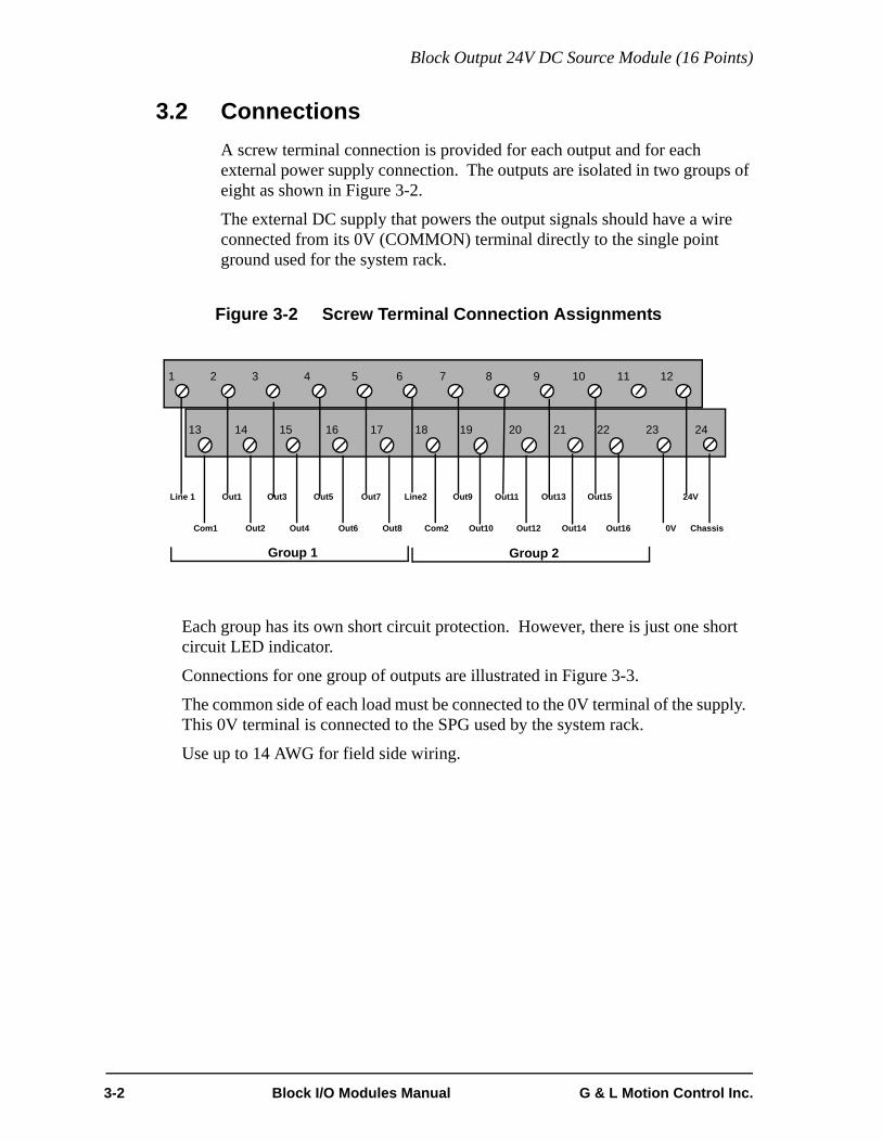
3.2 Connections A screw terminal connection is provided for each output and for each external power supply connection. The outputs are isolated in two groups of eight as shown in Figure 3-2.
The external DC supply that powers the output signals should have a wire connected from its 0V (COMMON) terminal directly to the single point ground used for the system rack.
Figure 3-2 Screw Terminal Connection Assignments
Each group has its own short circuit protection. However, there is just one short circuit LED indicator.
Connections for one group of outputs are illustrated in Figure 3-3.
The common side of each load must be connected to the 0V terminal of the supply. This 0V terminal is connected to the SPG used by the system rack.
Use up to 14 AWG for field side wiring.
Line 1
Com1
Out1 Out3 Out5 Out7 Line2 Out9 Out11 Out13 24VOut15
Out2 Out4 Out6 Out8 Com2 Out10 Out12 Out14 Out16 0V Chassis
Group 1 Group 2
1 2 3 4 5 6 7 8 9 10 11 12
13 14 15 16 17 18 19 20 21 22 23 24
3-2 Block I/O Modules Manual G & L Motion Control Inc.

Block Output 24V DC Source Module (16 Points)
Figure 3-3 Connections for One Group of Outputs
1 2 3 4 5
13 14 15 16 17
V+ 0VDCPowerSupply
To SPG
Line 1Com1
Out1Out2
Out3Out4
Out5Out6
Out7 Out8
G & L Motion Control Inc. Block I/O Modules Manual 3-3
Block Output 24V DC Source Module (16 Points)
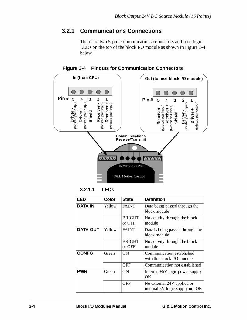
3.2.1 Communications Connections
There are two 5-pin communications connectors and four logic LEDs on the top of the block I/O module as shown in Figure 3-4 below.
Figure 3-4 Pinouts for Communication Connectors
3.2.1.1 LEDs
LED Color State DefinitionDATA IN Yellow FAINT Data being passed through the
block moduleBRIGHT or OFF
No activity through the block module
DATA OUT Yellow FAINT Data is being passed through the block module
BRIGHT or OFF
No activity through the block module
CONFG Green ON Communication established with this block I/O module
OFF Communication not establishedPWR Green ON Internal +5V logic power supply
OKOFF No external 24V applied or
internal 5V logic supply not OK
CommunicationsReceive/Transmit
In (from CPU) Out (to next block I/O module)
12345 12345Pin # Pin #R
ecei
ver +
(twis
ted
pair
inpu
t)
Rec
eive
r -(tw
iste
d pa
ir in
put)
Shie
ld
Driv
er -
Driv
er +
(twis
ted
pair
outp
ut)
(twis
ted
pair
outp
ut)
Driv
er +
(twis
ted
pair
outp
ut)
Driv
er -
(twis
ted
pair
outp
ut)
Shie
ld
Rec
eive
r -(tw
iste
d pa
ir in
put)
Rec
eive
r +(tw
iste
d pa
ir in
put)
G&L Motion Control
IN OUT CONF PWR
3-4 Block I/O Modules Manual G & L Motion Control Inc.

Block Output 24V DC Source Module (16 Points)
3.2.2 Protecting from an Inductive Load
Resistive loads can be connected to the module and controlled by the system with no precautions other than making sure they have a connection to the common of the DC power supply.
Inductive loads have an electrical “kickback” when current is stopped. This can damage or destroy the output switching device. Each output in the Output 24V DC module has a diode through which reverse current can be safely routed.
Figure 3-5 shows how the internal diode works with an inductive load. When an output is energized, represented in Figure 3-5a by a closed switch, current passes through the load into the common line. When the output is de-energized, represented in Figure 3-5b by an open switch, current stops and the inductive field collapses. The state of the outputs is controlled by the CPU module. This creates a reverse voltage across the load called “kickback” which tries to continue the current. The voltage is in series with the DC power supply. The combined voltage appears across the output switching device in the module.
If this were the only path available, voltage across the device would peak at several hundred volts. The internal diode provides another path for current. This limits the peak reverse voltage across the load to less than 1 V. Every switch in the Output 24V DC module has this protection so you can connect an inductive load to any terminal.
Figure 3-5 Diagram of Internal Protection for Inductive Loads
DC Power Supply
0V V+
DCL1
DCCOM1
INDUCTIVELOAD
DCOUT1
a) Output Energized
OUTPUT MODULE
OutputSwitchingDevice
DC Power Supply
0V V+
DCL1
DCCOM1
INDUCTIVELOAD
DCOUT1
b) Output De-energized
OUTPUT MODULE
OutputSwitchingDevice
G & L Motion Control Inc. Block I/O Modules Manual 3-5

Block Output 24V DC Source Module (16 Points)
3.3 Theory of OperationEach output point is a solid state switch rated at .5 A. It turns on or off according to the logic state sent to it by the CPU. If the CPU sends it a logic 1, the switch closes and the device is powered. If the CPU sends a logic 0, the switch opens and power to the device is cut off. The CPU updates the logic state for each switch every time it scans the program.
The logic side of the switch is optically isolated from the field side. An LED gives the logic state of each switch. If you need to know whether voltage is actually present at the field side, use a voltmeter on the terminal screws.
Each group has a .1 ohm series sensing resistor to protect against current overload in case the outputs are shorted to ground. When a short circuit condition is sensed, all outputs are pulsed on for approximately 130 microseconds every 100 millisecond. Normal operation resumes after the short is removed. In addition, each output is protected with internal clamping diodes. Without clamping, high voltage transients (kickback) from inductive loads might damage the module.
3-6 Block I/O Modules Manual G & L Motion Control Inc.

Block Output 24V DC Source Module (16 Points)
3.4 Specification Table
Characteristic Block Output 24V DC module specifications
Function Sources an external DC supply to 16 loads
Part number M.1017.3095
DC source requirements Nominal 24V DC; range 20 to 30 VDC
Field side connector Two 12-pin connectors, screw terminals
Protection of logic circuits Optical isolation between the logic and field side, transient suppression on the 24V external supply
Grouping of outputs Two groups of 8 solid-state switches. Each group may use its own DC supply, or one supply may be daisy-chained. These must be referenced to 0V.
Short circuit protection for each group Pulses output for about 130 µsec every 100 msec until short is removed
Maximum current per group 4 A of continuous current for the group; each switch is rated at .5 A continuous
Logic side LEDs, module status Data In LEDData Out LEDConfigured LEDPower LED
Logic side LEDs, output status A yellow LED for each output
Logic side LED, short circuit status A red LED lights to indicate a short circuit condition
Switch characteristics Solid-state switches
Time delay on for resistive loads 50 µsec max
Time delay off for resistive loads 50 µsec max
Leakage current in off state 0.5 mA max
Switch voltage, maximum ON 1 VDC max
Surge current, maximum 25 A for 130 µsec, every 100 msec
Response to scan loss All outputs are reset to the OFF state
Module power requirements 100 mA from an external 24V DC supply (20 to 30V DC range)NOTE: 2.5A, 250 microsecond inrush at power on
G & L Motion Control Inc. Block I/O Modules Manual 3-7

Block Output 24V DC Source Module (16 Points)
CE Marked Conforms to Directives 73/23/EEC, 89/336/EEC, 92/31/EEC, 93/68/EEC by conforming to the following stan-dards:EN 50081-2:1993 EMC Generic Industrial EmissionsEN 50082-2:1995 EMC Generic Industrial ImmunityEN 61131-2:1994/A11:1996 Low voltage directive requirements for programmable controllersOperates with emissions below EN55011/ CISPR 11Class A limitsImmune to:• Electrostatic discharge (4K V contact mode, 8K V air discharge) per EN61000-4-2• RF electromagnetic fields per EN61000-4-3, ENV 50141, and ENV50204• Electrical fast transients per EN61000-4-4 • Magnetic fields per EN61000-4-8Refer to the EMC Guidelines for more information.
UL and C/UL Listed File No. E126417 NRAQ Programmable Controllers
Operating temperature range 7° C to 55° C (45° F to 131° F)
Storage temperature range -40° C to 85° C (-40° F to 185° F)
Humidity 5 to 95%, non-condensing
Physical size 4.05" wide x 4.825" high x 3" deep 102.9 mm x 122.6 mm x 76.2 mm
Vibration (per IEC 68-2-6) 10-57 Hz (constant amplitude .15 mm)57 - 2000 Hz (acceleration 2 g)
Shock (per IEC 68-2-27) Four shocks per axis (15g/11 msec)
3-8 Block I/O Modules Manual G & L Motion Control Inc.

Block Input 24V DC Module (16 points)
4 Block Input 24V DC Module (16 points)
4.1 IntroductionThe input 24V DC module converts DC signals from devices into logic levels that the CPU can use. Each signal is converted into a corresponding logic 1 or 0 which is transmitted through the communication interface to the CPU module. An “on” signal is nominally 24 VDC, but can be any level between 15 and 30 volts. An “off” signal is any level below 5V. The wiring configurations may be sink or source.
Figure 4-1 Block Input 24V DC Module 16 point
CommunicationsReceive/Transmit
Connector
ScrewTerminal
OUTPUT 24VDC SINK SOURCE
G&L Motion Control
IN OUT CONF PWR
Cover(shown open)
Communication/Status LEDs
LEDsOutput Status
G & L Motion Control Inc. Block I/O Modules Manual 4-1

Block Input 24V DC Module (16 points)
4.2 Connections A screw terminal connector is provided for each input and for each external power supply connection. The inputs are isolated in two groups of eight, with one additional terminal per group for the DC source/sink connection. The devices connected to terminals in the same group have a common DC supply and are wired in the same configuration, sink or source (Figure 4-2).
The external DC supply that powers the input signals should have a wire connected from its 0V (COMMON) terminal directly to the single-point ground used for the system rack.
Figure 4-2 Screw Terminal Connector Assignments
Typically, an external 24V DC supply is connected to pins 18 and 35. These pins are internally jumpered so that the supply is available at the other pins labeled as 24V and 0V. This makes it convenient to connect a 3-wire device (e.g., a proximity switch) which requires a voltage and ground connection. Also, 24V or 0V can be easily jumpered to a group’s sink/source connection.
Figure 4-3 illustrates two groups of inputs using the same power supply. Each group can work independently of the other; one group may be sink and the other source. The DC power supply for each group may be different if required, but must be referenced to the same ground. Typically just one DC power supply is used, daisy-chained from one group to the next.
In Figure 4-3a, one group of eight inputs is shown with devices “sinking” current through the block DC Input module. The HOT terminal of the power supply is connected internally to the module by the jumper between 24V and Group 1 or 2 SS. The second group of eight inputs is shown with devices “sourcing” current through the block DC Input module. The COMMON terminal of the power supply is connected internally to the module by the jumper between 0V and Group 2 or 1 SS.
In Figure 4-3b, the first group is shown with devices “sourcing” current through the block DC Input module. The second group is shown with devices “sinking” current through the block DC Input module. In both examples the DC power supply is the same for Group 1 and 2. Use up to 14 AWG for field side wiring.
1 3 4 5 6 7 8 9 10 11 12 13 14 15 16 17 182
19 21 22 23 24 25 26 27 28 29 30 31 32 33 34 35 3620
Chassis
24V
0V
24V
Group 2 SS
24V
0V0V
24V
0V
24V
0V
24V In1
In2
In3
In4
In5
In6
In7
In8
In9
In10
In11
In12
In13
In14
In15
In16
Group 1 SS
24V
0V
24V
0V
4-2 Block I/O Modules Manual G & L Motion Control Inc.

Block Input 24V DC Module (16 points)
Figure 4-3 Connectors for Two Groups of Inputs
1 2 3 4 5 6 7 8 9 10 11 12IN
1
IN 2
13 14 15 16 17 18
19 20 21 22 23 24 25 26 27 28 29 30 31 32 33 34 35 36IN
4
IN 3
IN 5
IN 6
IN 7
IN 8
Gro
up1
SS
24V
IN 9
IN 1
0
IN 1
1
IN 1
2
Common
IN 1
3
IN 1
4
IN 1
5IN
16
Gro
up2
SS
0V
0V V+
DC PowerSupply
Hot
Group 2
Source
Group 1
Sink
1 2 3 4 5 6 7 8 9 10 11 12
IN 1
IN 2
13 14 15 16 17 18
19 20 21 22 23 24 25 26 27 28 29 30 31 32 33 34 35 36
IN 4
IN 3
IN 5
IN 6
IN 7
IN 8
Gro
up1
SS
0V
IN 9
IN 1
0
IN 1
1
IN 1
2
Hot
IN 1
3
IN 1
4
IN 1
5IN
16
Gro
up2
SS
24V
0V V+
DC PowerSupply
Common
Group 2
Sink
Group 1
Source
a. Group 1 Sink (Pins 8 and 9 Jumpered) and Group 2 Source (Pins 33 and 34 Jumpered)
b. Group 1 Source (Pins 25 and 26 Jumpered) and Group 2 Sink (Pins 16 and 17 Jumpered)
G & L Motion Control Inc. Block I/O Modules Manual 4-3

Block Input 24V DC Module (16 points)
4.2.1 Communications Connections
There are two 5-pin communications connectors and four logic LEDs on the top of the block I/O module as shown in Figure 4-4.
Figure 4-4 Pinouts for Communication Connectors
4.2.1.1 LEDs
LED Color State DefinitionDATA IN Yellow FAINT Data being passed through the block
moduleBRIGHT or OFF
No activity through the block module
DATA OUT
Yellow FAINT Data is being passed through the block module
BRIGHT or OFF
No activity through the block module
CONFG Green ON Communication established with this block I/O module
OFF Communication not establishedPWR Green ON Internal +5V logic power supply OK
OFF No external 24V applied or internal 5V logic supply not OK
CommunicationsReceive/Transmit
In (from CPU) Out (to next block I/O module)
12345 12345Pin # Pin #
Rec
eive
r +(tw
iste
d pa
ir in
put)
Rec
eive
r -(tw
iste
d pa
ir in
put)
Shie
ld
Driv
er -
Driv
er +
(twis
ted
pair
outp
ut)
(twis
ted
pair
outp
ut)
Driv
er +
(twis
ted
pair
outp
ut)
Driv
er -
(twis
ted
pair
outp
ut)
Shie
ld
Rec
eive
r -(tw
iste
d pa
ir in
put)
Rec
eive
r +(tw
iste
d pa
ir in
put)
G&L Motion Control
IN OUT CONF PWR
4-4 Block I/O Modules Manual G & L Motion Control Inc.

Block Input 24V DC Module (16 points)
4.3 Theory of OperationEach input is guaranteed “on” at 15 to 30 VDC and guaranteed “off” at 0 to 5 VDC; polarity doesn't matter. Its on/off state is converted to a corresponding logic 1 or 0. This logic state is transmitted through the communication interface to the CPU module, where the processor uses it as data in the ladder program. The logic side of the input is optically isolated from the field side.
An LED in the upper section of the module indicates the logic state of each input. Each group is represented by a horizontal row of LEDs. If you need to know whether voltage is present at the field side, use a voltmeter on the terminal screws. The shaded blocks in Figure 4-5 show the limits specified by the IEC. The lines show the maximum and minimum V/I of the inputs in this module. The voltage/current curve in this graph shows that the input module is well within the IEC Type 1 limits.
Figure 4-5 Input Characteristics Compared to IEC Standards
U in VoltsUHMAX 30
UNOM 2425
“ON” REGION
20
UHMIN 15(UTMAX)
10
5
0
-5
.5 2 4 6 8 10 12 14 15ITMIN IHMIN
INPUT CURRENT
I inmAMPS
TRANSITION REGION
“OFF” REGION
IMAX
(UTMIN )ULMAX
INPU
T VO
LTA
GE
MIN MAX
G & L Motion Control Inc. Block I/O Modules Manual 4-5

Block Input 24V DC Module (16 points)
IMPORTANT
Switching devices can sometimes have a leakage current that ex-ceeds the ITmin (current allowed when off) of an input module. In or-der to use such a device, an impedance (typically, a resistor) needs tobe used in parallel with the input.For example, some of the newer proximity switches use two wires in-stead of three. The third wire was used for a power or ground line.Without the third wire, the switch is easier to install. However, it re-quires more leakage current in the off state to power its internal cir-cuitry.As a conservative estimate, use the following formula to calculate anexternal resistance value. It keeps the input voltage at or below 2.4Vwhen the switching device is in the "off" state.
If the switch leakage specification is ≤ 1.7 mA, then:
Use a resistor less than or equal to 2.5 KΩ. Be sure that the wattageis adequate for the resistor when the switching device is in the “on”state remembering that:
2.4VSwitch Leakage 0.75mA–--------------------------------------------------------------- R≥
2.4V1.7 0.75mA–-------------------------------- 2.5KΩ≥
PVON
2
R----------=
4-6 Block I/O Modules Manual G & L Motion Control Inc.

Block Input 24V DC Module (16 points)
4.4 Specification TableCharacteristic Block Input 24V DC module specifications
Function Monitors on/off states from DC voltage inputs
Part number M.1017.3092
Field side connector Two 18-pin connectors, screw terminals
Input signals (meet IEC standards) Nominal 24 VDC on, 0 VDC off
UH Max (max. allowed voltage) 30 VDC
IH Max (max. current @ 30 VDC) 7.5 mA
UL Min Polarity independent
Guaranteed on 15 VDC
IH Min (min. current @ UH Min) 2.8 mA
Guaranteed off 5 VDC
IT Min (current allowed when off) .75 mA
Time delay on 1 ms max.
Time delay off 1 ms max.
Protection of logic circuits Optical isolation between the logic and field sides, tran-sient suppression on the 24V external supply
Logic side LEDs, module status Data In LEDData Out LEDConfigured LEDPower LED
Logic side LEDs, input circuits A yellow LED for each input
Module power requirements 100 mA from an external 24V DC supply (20 to 30V DC range)NOTE: 2.5A, 250 microsecond inrush at power on
G & L Motion Control Inc. Block I/O Modules Manual 4-7

Block Input 24V DC Module (16 points)
CE Marked Conforms to Directives 73/23/EEC, 89/336/EEC, 92/31/EEC, 93/68/EEC by conforming to the following stan-dards:EN 50081-2:1993 EMC Generic Industrial EmissionsEN 50082-2:1995 EMC Generic Industrial ImmunityEN 61131-2:1994/A11:1996 Low voltage directive requirements for programmable controllersOperates with emissions below EN55011/ CISPR 11Class A limitsImmune to:• Electrostatic discharge (4K V contact mode, 8K V air discharge) per EN61000-4-2• RF electromagnetic fields per EN61000-4-3, ENV 50141, and ENV50204• Electrical fast transients per EN61000-4-4 • Magnetic fields per EN61000-4-8Refer to the EMC Guidelines for more information.
UL and C/UL Listed File No. E126417 NRAQ Programmable Controllers
Operating temperature range 7° C to 55° C (45° F to 131° F)
Storage temperature range -40° C to 85° C (-40° F to 185° F)
Humidity 5 to 95%, non-condensing
Physical size 4.05" wide x 4.825" high x 3" deep 102.9 mm x 122.6 mm x 76.2 mm
Vibration (per IEC 68-2-6) 10-57 Hz (constant amplitude .15 mm)57 - 2000 Hz (acceleration 2 g)
Shock (per IEC 68-2-27) Four shocks per axis (15g/11 msec)
4-8 Block I/O Modules Manual G & L Motion Control Inc.

Block 24V DC 8 In/8 Out Module
5 Block 24V DC 8 In/8 Out Module
5.1 IntroductionThe Block 24V DC 8/8 module provides eight output points and eight input points.
The eight point output section sources voltage for individual loads from a DC power supply. The external supply is nominally 24 volts, but can be between 20 and 30 volts. Eight LEDs near the field terminal connector of the module indicate the logic state that drives each output. Another LED labeled SC turns on if any output attempts to drive a short circuit.
The eight point input section converts DC signals from devices into logic levels that the CPU can use. Each signal is converted into a corresponding logic 1 or 0 which is transmitted through the communication interface to the CPU module. An “on” signal is nominally 24 VDC, but can be any level between 15 and 30 volts. An “off” signal is any level below 5V. The wiring configurations may be sink or source. Eight LEDs near the field terminal connector of the module indicate the logic state of each input.
Figure 5-1 Block 24V DC Output/Input Module (8/8 Point)
CommunicationsReceive/Transmit
Connector
ScrewTerminal
OUTPUT 24V DC
G&L Motion Control
IN OUT CONF PWR
Cover(shown open)
Short Circuit LED
Input StatusLEDs
Communication/Status LEDs
LEDsOutput Status
G & L Motion Control Inc. Block I/O Modules Manual 5-1
Block 24V DC 8 In/8 Out Module
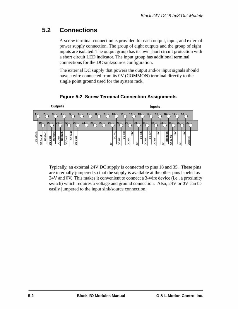
5.2 Connections A screw terminal connection is provided for each output, input, and external power supply connection. The group of eight outputs and the group of eight inputs are isolated. The output group has its own short circuit protection with a short circuit LED indicator. The input group has additional terminal connections for the DC sink/source configuration.
The external DC supply that powers the output and/or input signals should have a wire connected from its 0V (COMMON) terminal directly to the single point ground used for the system rack.
Figure 5-2 Screw Terminal Connection Assignments
Typically, an external 24V DC supply is connected to pins 18 and 35. These pins are internally jumpered so that the supply is available at the other pins labeled as 24V and 0V. This makes it convenient to connect a 3-wire device (i.e., a proximity switch) which requires a voltage and ground connection. Also, 24V or 0V can be easily jumpered to the input sink/source connection.
1 3 4 5 6 7 8 9 10 11 12 13 14 15 16 17 182
19 21 22 23 24 25 26 27 28 29 30 31 32 33 34 35 3620
DC
Lin
e 1
DC
Com
1
DC
Out
1
DC
Out
3
DC
Out
5
DC
Out
7
DC
IN4
DC
IN6
24V
DC
IN8
DC
Out
2
DC
Out
4
DC
Out
6
DC
Out
8
DC
IN2 D
C IN
5
DC
IN7
DC
IN S
S
0V Cha
ssis
Outputs0V 0V 0V
24V
DC
IN S
S
DC
IN3
DC
IN1
24V
24V
Inputs
5-2 Block I/O Modules Manual G & L Motion Control Inc.

Block 24V DC 8 In/8 Out Module
Connections for the outputs are illustrated in Figure 5-3.
The common side of each load must be connected to the 0V terminal of the supply. This 0V terminal is connected to the SPG used by the system rack.
Use up to 14 AWG for field side wiring.
Figure 5-3 Connections for the Outputs
1 2 3 4 5
19 20 21 22 23
V+ 0VDCPowerSupply
To SPG
Line 1Com1
Out1Out2
Out3Out4
Out5Out6
Out7 Out8
G & L Motion Control Inc. Block I/O Modules Manual 5-3

Block 24V DC 8 In/8 Out Module
Connections for the inputs are illustrated in Figure Figure 5-4.
The eight inputs on the left are shown with devices “sourcing” current through the block module. The COMMON terminal of the power supply is connected inter-nally to the module by the jumper between 0V and the DC IN SS.
The eight inputs in the example on the right are shown with devices “sinking” cur-rent through the block module. The HOT terminal of the power supply is con-nected internally to the module by the jumper between 24V and DC IN SS.
Use up to 14 AWG for field side wiring.
Figure 5-4 Connectors for Inputs
10 11 12 13 14 15 16 17 18
28 29 30 31 32 33 34 35 36
DC
IN 1
DC
IN S
S
0V
0V V+
DC PowerSupply
Hot
Source
DC
IN 2
DC
IN 3
DC
IN 4
DC
IN 5
DC
IN 6
DC
IN 7
DC
IN 8
10 11 12 13 14 15 16 17 18
28 29 30 31 32 33 34 35 36
DC
IN 1
DC
IN S
S
0V V+
DC PowerSupply
Common
Sink
DC
IN 2
DC
IN 3
DC
IN 4
DC
IN 5
DC
IN 6
DC
IN 7
DC
IN 8
24V
5-4 Block I/O Modules Manual G & L Motion Control Inc.

Block 24V DC 8 In/8 Out Module
5.2.1 Communications Connections
There are two 5-pin communications connectors and four logic LEDs on the top of the block I/O module as shown in Figure 5-5.
Figure 5-5 Pinouts for Communication Connectors
5.2.1.1 LEDs
LED Color State DefinitionDATA IN Yellow FAINT Data being passed through the block
moduleBRIGHT or OFF
No activity through the block module
DATA OUT
Yellow FAINT Data is being passed through the block module
BRIGHT or OFF
No activity through the block module
CONFG Green ON Communication established with this block I/O module
OFF Communication not establishedPWR Green ON Internal +5V logic power supply
OKOFF No external 24V applied or inter-
nal 5V logic supply not OK
CommunicationsReceive/Transmit
G&L Motion Control
IN OUT CONF PWR
In (from CPU) Out (to next block I/O module)
12345 12345Pin # Pin #
Rec
eive
r +(tw
iste
d pa
ir in
put)
Rec
eive
r -(tw
iste
d pa
ir in
put)
Shie
ld
Driv
er -
Driv
er +
(twis
ted
pair
outp
ut)
(twis
ted
pair
outp
ut)
Driv
er +
(twis
ted
pair
outp
ut)
Driv
er -
(twis
ted
pair
outp
ut)
Shie
ld
Rec
eive
r -(tw
iste
d pa
ir in
put)
Rec
eive
r +(tw
iste
d pa
ir in
put)
G & L Motion Control Inc. Block I/O Modules Manual 5-5

Block 24V DC 8 In/8 Out Module
5.2.2 Protecting from an Inductive Load
Resistive loads can be connected to the module and controlled by the system with no precautions other than making sure they have a connection to the common of the DC power supply.
Inductive loads have an electrical “kickback” when current is stopped. This can damage or destroy the output switching device. Each output in the Output 24V DC module has a diode through which reverse current can be safely routed.
Figure 5-6 shows how the internal diode works with an inductive load. When an output is energized, represented in Figure Figure 5-6a by a closed switch, current passes through the load into the common line. When the output is de-energized, represented in Figure 5-6b by an open switch, current stops and the inductive field collapses. The state of the outputs is controlled by the CPU module. This creates a reverse voltage across the load called “kickback” which tries to continue the current. The voltage is in series with the DC power supply. The combined voltage appears across the output switching device in the module.
If this were the only path available, voltage across the device would peak at several hundred volts. The internal diode provides another path for current. This limits the peak reverse voltage across the load to less than 1 V. Every switch in the Output 24V DC module has this protection so you can connect an inductive load to any terminal.
Figure 5-6 Diagram of Internal Protection for Inductive Loads
DC Power Supply
0V V+
DCL1
DCCOM1
INDUCTIVELOAD
DCOUT1
a) Output Energized
OUTPUT MODULE
OutputSwitchingDevice
DC Power Supply
0V V+
DCL1
DCCOM1
INDUCTIVELOAD
DCOUT1
b) Output De-energized
OUTPUT MODULE
OutputSwitchingDevice
5-6 Block I/O Modules Manual G & L Motion Control Inc.

Block 24V DC 8 In/8 Out Module
5.3 Theory of Operation
5.3.1 Outputs
Each output point is a solid state switch rated at .5 A. It turns on or off according to the logic state sent to it by the CPU. If the CPU sends it a logic 1, the switch closes and the device is powered. If the CPU sends a logic 0, the switch opens and power to the device is cut off. The CPU updates the logic state for each switch every time it scans the program.
The logic side of the switch is optically isolated from the field side. An LED gives the logic state of each switch. If you need to know whether voltage is actually present at the field side, use a voltmeter on the terminal screws.
The group of outputs has a .1 ohm series sensing resistor to protect against current overload in case the outputs are shorted to ground. When a short circuit condition is sensed, all outputs are pulsed on for approximately 130 microseconds every 100 milliseconds. Normal operation resumes after the short is removed. In addition, each output is protected with internal clamping diodes. Without clamping, high voltage transients (kickback) from inductive loads might damage the module.
5.3.2 Inputs
Each input is guaranteed “on” at 15 to 30 VDC and guaranteed “off” at 0 to 5 VDC; polarity doesn't matter. Its on/off state is converted to a corresponding logic 1 or 0. This logic state is transmitted through the communication interface to the CPU module, where the processor uses it as data in the ladder program. The logic side of the input is optically isolated from the field side.
An LED in the upper section of the module indicates the logic state of each input. The group of inputs is represented by a horizontal row of LEDs. If you need to know whether voltage is present at the field side, use a voltmeter on the terminal screws.
The shaded blocks in Figure 5-7 show the limits specified by the IEC. The lines show the maximum and minimum V/I of the inputs in this module. The voltage/current curve in this graph shows that the input module is well within the IEC Type 1 limits.
G & L Motion Control Inc. Block I/O Modules Manual 5-7

Block 24V DC 8 In/8 Out Module
Figure 5-7 Input Characteristics Compared to IEC Standards
U in VoltsUHMAX 30
UNOM 2425
“ON” REGION
20
UHMIN 15(UTMAX)
10
5
0
-5
.5 2 4 6 8 10 12 14 15ITMIN IHMIN
INPUT CURRENT
I inmAMPS
TRANSITION REGION
“OFF” REGION
IMAX
(UTMIN )ULMAX
INPU
T VO
LTA
GE
MIN MAX
5-8 Block I/O Modules Manual G & L Motion Control Inc.

Block 24V DC 8 In/8 Out Module
IMPORTANT
Switching devices can sometimes have a leakage current that ex-ceeds the ITmin (current allowed when off) of an input module. In or-der to use such a device, an impedance (typically, a resistor) needs tobe used in parallel with the input.For example, some of the newer proximity switches use two wires in-stead of three. The third wire was used for a power or ground line.Without the third wire, the switch is easier to install. However, it re-quires more leakage current in the off state to power its internal cir-cuitry.As a conservative estimate, use the following formula to calculate anexternal resistance value. It keeps the input voltage at or below 2.4Vwhen the switching device is in the "off" state.
If the switch leakage specification is ≤ 1.7 mA, then:
Use a resistor less than or equal to 2.5 KΩ. Be sure that the wattageis adequate for the resistor when the switching device is in the “on”state remembering that:
2.4VSwitch Leakage 0.75mA–--------------------------------------------------------------- R≥
2.4V1.7 0.75mA–-------------------------------- 2.5KΩ≥
PVON
2
R----------=
G & L Motion Control Inc. Block I/O Modules Manual 5-9

Block 24V DC 8 In/8 Out Module
5.4 Specification TableCharacteristic Block 24V DC module (8 In/8Out) specifications
Function Monitors on/off states from eight DC voltage inputs and sources an external DC supply to eight loads
Part number M. 1017.3090
Field side connector Two 18-pin connectors, screw terminals
Protection of logic circuits Optical isolation between the logic and field sides, tran-sient suppression for the 24V external supply
Logic side LEDs, module status Data In LEDData Out LEDConfigured LEDPower LED
Logic side LEDs, input status A yellow LED for each input
Logic side LEDs, output status A yellow LED for each output
Logic side LED, short circuit status A red LED lights to indicate a short circuit condition
Module power requirements 100 mA from an external 24V DC supply (20 to 30V DC range)NOTE: 2.5A, 250 microsecond inrush at power on
CE Marked Conforms to Directives 73/23/EEC, 89/336/EEC, 92/31/EEC, 93/68/EEC by conforming to the following stan-dards:EN 50081-2:1993 EMC Generic Industrial EmissionsEN 50082-2:1995 EMC Generic Industrial ImmunityEN 61131-2:1994/A11:1996 Low voltage directive requirements for programmable controllersOperates with emissions below EN55011/ CISPR 11Class A limitsImmune to:• Electrostatic discharge (4K V contact mode, 8K V air discharge) per EN61000-4-2• RF electromagnetic fields per EN61000-4-3, ENV 50141, and ENV50204• Electrical fast transients per EN61000-4-4 • Magnetic fields per EN61000-4-8Refer to the EMC Guidelines for more information.
UL and C/UL Listed File No. E126417 NRAQ Programmable Controllers
Operating temperature range 7° C to 55° C (45° F to 131° F)
Storage temperature range -40° C to 85° C (-40° F to 185° F)
Humidity 5 to 95%, non-condensing
5-10 Block I/O Modules Manual G & L Motion Control Inc.

Block 24V DC 8 In/8 Out Module
Physical size 4.05" wide x 4.825" high x 3" deep 102.9 mm x 122.6 mm x 76.2 mm
UL Listing and CE Marking File No. E126417 NRAQ Programmable Controllers
Input Section
Input signals Nominal 24 VDC on, 0 VDC off, conforming to IEC Type 1 inputs per IEC 1131-2
UH Max (max. allowed voltage) 30 VDC
IH Max (max. current @ 30 VDC) 7.5 mA
UL Min Polarity independent
Guaranteed on 15 VDC
IH Min (min. current @ UH Min) 2.8 mA
Guaranteed off 5 VDC
IT Min (current allowed when off) .75 mA
Time delay on 1 ms max.
Time delay off 1 ms max.
Output Section
DC source requirements Nominal 24V DC; range 20 to 30V DC
Output group One group of eight solid-state switches. The group uses an external DC supply. It must be referenced to SPG.
Short circuit protection for the group Pulses output for about 130 µsec every 100 msec until short is removed
Maximum current per group 4 A of continuous current for the group; each switch is rated at .5 A continuous
Switch characteristics Solid-state switches
Time delay on for resistive loads 50 µsec max
Time delay off for resistive loads 50 µsec max
Leakage current in off state 0.5 mA max
Switch voltage, maximum ON 1 VDC max
Surge current, maximum 25 A for about 130 µsec every 100 msec
Response to scan loss All outputs are reset to the OFF state
Vibration (per IEC 68-2-6) 10-57 Hz (constant amplitude .15 mm)57 - 2000 Hz (acceleration 2 g)
Shock (per IEC 68-2-27) Four shocks per axis (15g/11 msec)
G & L Motion Control Inc. Block I/O Modules Manual 5-11

Block 24V DC 8 In/8 Out Module
THIS PAGE INTENTIONALLY BLANK
5-12 Block I/O Modules Manual G & L Motion Control Inc.
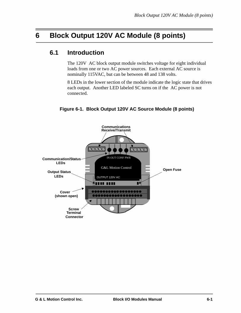
Block Output 120V AC Module (8 points)
6 Block Output 120V AC Module (8 points)
6.1 IntroductionThe 120V AC block output module switches voltage for eight individual loads from one or two AC power sources. Each external AC source is nominally 115VAC, but can be between 48 and 138 volts.
8 LEDs in the lower section of the module indicate the logic state that drives each output. Another LED labeled SC turns on if the AC power is not connected.
Figure 6-1. Block Output 120V AC Source Module (8 points)
CommunicationsReceive/Transmit
Connector
ScrewTerminal
OUTPUT 120V AC
G&L Motion Control
IN OUT CONF PWR
Cover(shown open)
Open Fuse
Communication/Status LEDs
LEDsOutput Status
G & L Motion Control Inc. Block I/O Modules Manual 6-1

Block Output 120V AC Module (8 points)
6.2 ConnectionsA screw terminal is provided for each output and for power connections. Theoutputs are optically isolated and separated into two groups of four. The external devices in each group must use the same power source. The outputs must not be paralleled or tied together.
The power to operate the module is brought in through pins 12 and 23, +24 volt and 24 volt COM, respectively. Pin 24 Chassis GND need not be connected if the block is DIN rail mounted.
Figure 6-2. Screw Terminal Connections
NOTE
To conform to CE requirements for a positive earth connection, con-nect a 6 inch (or less) #14 AWG (2 mm wire) from the chassis pin toearth.
1 2 3 4 5 6 7 8 9 10 11 12
13 14 15 16 17 18 19 20 21 22 23 24
ChassisGND
24V COM
+ 24 VAC
C0M
1
AC
OU
T 1
AC
IN 1
Group 1
AC
OU
T 8
ACIN1-ACCOM1Group 2
ACIN2-ACCOM2
120 VAC
Fuse
RelayFuse
AC
OU
T 2
AC
OU
T 3
AC
OU
T 4
AC
OU
T 5
AC
OU
T 6
AC
OU
T 7
AC
C0M
2
AC
IN 2
Relay
Relay
Relay
Relay
Relay
Relay
Relay
6-2 Block I/O Modules Manual G & L Motion Control Inc.

Block Output 120V AC Module (8 points)
6.2.1 Fusing
External fuses are required (see fusing recommendations) and each of the two AC inputs should be fused separately unless current requirements are less than 3 amps total.
6.2.1.1 Fuse Monitor
If AC power is disrupted to the unit, a short circuit/blown fuse LED indicator will be lit and a software monitoring bit will be enabled in the block I/O data message.
For the fuse monitor to work correctly when only the first block of 4 outputs is used, jumper ACIN1 to ACIN2 and ACCOM1 to ACCOM2.
G & L Motion Control Inc. Block I/O Modules Manual 6-3

Block Output 120V AC Module (8 points)
6.2.2 Communications Connections
There are two 5-pin communications connectors and four logic LEDs on the top of the block I/O module as shown in Figure 6-3.
Figure 6-3. Pinouts for Communication Connectors
6.2.2.1 LEDs
LED Color State DefinitionDATA IN Yellow FAINT Data being passed through the block
moduleBRIGHT or OFF
No activity through the block module
DATA OUT
Yellow FAINT Data is being passed through the block module
BRIGHT or OFF
No activity through the block module
CONFG Green ON Communication established with this block I/O module
OFF Communication not establishedPWR Green ON Internal +5V logic power supply OK
OFF No external 24V applied or internal 5V logic supply not OK
CommunicationsReceive/Transmit
In (from CPU) Out (to next block I/O module)
12345 12345Pin # Pin #
Rec
eive
r +(tw
iste
d pa
ir in
put)
Rec
eive
r -(tw
iste
d pa
ir in
put)
Shie
ld
Driv
er -
Driv
er +
(twis
ted
pair
outp
ut)
(twis
ted
pair
outp
ut)
Driv
er +
(twis
ted
pair
outp
ut)
Driv
er -
(twis
ted
pair
outp
ut)
Shie
ld
Rec
eive
r -(tw
iste
d pa
ir in
put)
Rec
eive
r +(tw
iste
d pa
ir in
put)
G&L Motion Control
IN OUT CONF PWR
6-4 Block I/O Modules Manual G & L Motion Control Inc.

Block Output 120V AC Module (8 points)
6.2.3 Protecting from an Inductive Load
Arc suppression is not required for a non-inductive load or for an inductive load switched only by the Output 120V AC module.
6.3 Theory of OperationEach output point is a solid state switch rated at .75A continuous for the 8 point module. It turns on or off according to the logic state sent to it by the CPU. If the CPU sends it a logic 1, the switch closes and the load is powered. If the CPU sends a logic 0, the switch opens and power to the load is removed. The CPU updates the logic state for each switch every time it scans the program.
The logic side of the switch is optically isolated from the field side. An LED gives the logic state of each output. If you need to know whether voltage is actually on at the field side, use a voltmeter on the terminal screws.
The output switch is turned on near the zero voltage crossing of the AC power source and is turned off at zero current.
Each group requires an external fuse in series with the source to protect against current overload in case the outputs are shorted to ground.
G & L Motion Control Inc. Block I/O Modules Manual 6-5

Block Output 120V AC Module (8 points)
6.4 Specification Table
Characteristic Block Output 120V AC module (8 Point)
Function Switches an external AC source to 8 loads
Part number M.1300.4948
AC source requirements Nominal 115 VAC, range 48 to 138 VAC
Field side connector Two 12-pin connectors, screw terminals
Protection of logic circuits Optical isolation between the logic and field side;Transient protection on outputs.
Arrangement of outputs Two groups of 4 solid-state switches. Each group can use its own AC source, or one source can be daisy-chained. UL 508 spacing
Fuse per group of 4 Fast-acting, UL rated 3A
Maximum current per group 2A of continuous current for the group;4 points each switch is rated at .75 A continuous
Indicator lights, output circuits An LED for each output
Indicator light, module A DIAG LED turns OFF when the module passes its diagnos-tic tests at power-on.
Indicator light, fuses A logic side LED lights to indicate a condition when power to a group is missing or has an open fuse.
Switch characteristics Solid-state switches.
Switch voltage, maximum ON 1V AC @ .75A RMS
Surge current, maximum 20 A for 2 cycles, every 2 seconds; fuse blows if this is exceeded.
Frequency 50 / 60 Hz. ± 5%
Time delay on, maximum 1/2 cycle (turns on at zero voltage)
Time delay off, maximum 1/2 cycle (turns off at zero voltage)
Minimum load current 50 mA
Leakage current in OFF state, maxi-mum
4 mA @ 120 VAC
Logic side LEDs, module status Data In LEDData Out LEDConfigured LEDPower LED
Logic side LEDs, input circuits A yellow LED for each input
6-6 Block I/O Modules Manual G & L Motion Control Inc.

Block Output 120V AC Module (8 points)
Module power requirements 65 mA from an external 24V DC supply (20 to 30V DC range)NOTE: 2.5A, 250 microsecond inrush at power on
CE Marked Conforms to Directives 73/23/EEC, 89/336/EEC, 92/31/EEC, 93/68/EEC by conforming to the following standards:EN 50081-2:1993 EMC Generic Industrial EmissionsEN 50082-2:1995 EMC Generic Industrial ImmunityEN 61131-2:1994/A11:1996 Low voltage directive require-ments for programmable controllersOperates with emissions below EN55011/ CISPR 11Class A limitsImmune to:• Electrostatic discharge (4K V contact mode, 8K V air dis-charge) per EN61000-4-2• RF electromagnetic fields per EN61000-4-3, ENV 50141, and ENV50204• Electrical fast transients per EN61000-4-4 • Magnetic fields per EN61000-4-8Refer to the EMC Guidelines for more information.
UL and C/UL Listed File No. E126417 NRAQ Programmable Controllers
Operating temperature range 7° C to 55° C (45° F to 131° F) *
Storage temperature range -40° C to 85° C (-40° F to 185° F)
Humidity 5 to 95%, non-condensing
Physical size 4.05" wide x 4.825" high x 3" deep 102.9 mm x 122.6 mm x 76.2 mm
Vibration (per IEC 68-2-6) 10-57 Hz (constant amplitude .15 mm)57 - 2000 Hz (acceleration 2 g)
Shock (per IEC 68-2-27) Four shocks per axis (15g/11 msec)
G & L Motion Control Inc. Block I/O Modules Manual 6-7

Block Output 120V AC Module (8 points)
THIS PAGE INTENTIONALLY BLANK
6-8 Block I/O Modules Manual G & L Motion Control Inc.

Block Relay Module (8 points)
7 Block Relay Module (8 points)
7.1 IntroductionThe relay output module can switch eight relay contacts. Four relays are normally open (NO)/normally closed (NC) form C type and four are normally open (NO) form A type.
Eight LEDs in the upper section of the module indicate the logic state that drives each relay.
Figure 7-1 Block Relay Module (8 Point)
CommunicationsReceive/Transmit
Connector
ScrewTerminal
BLOCK RELAY
G&L Motion Control
IN OUT CONF PWR
Cover(shown open)
Communication/Status LEDs
LEDsOutput Status
G & L Motion Control Inc. Block I/O Modules Manual 7-1

Block Relay Module (8 points)
7.2 Connections A screw terminal connection is provided for each side of the contact. The form C type has three connections; normally open (NO), normally closed (NC), and the common terminal (CT). Only two of the connections can be wired at any time. The common terminal connection must be wired with either the normally open or the normally closed connection depending on the application.
The form A type has two connections; one for each side of the contact.
Figure 7-2 Screw Terminal Connector Assignments
NOTE
To conform to CE requirements for a positive earth connection, con-nect a 6 inch (or less) #14 AWG (2 mm wire) from the chassis pin toearth.
NO 1
Chassis
1 2 3 4 5 6 7 8 9 10 11 12
13 14 15 16 17 18 19 20 21 22 23 24
GND24 COM
+ 24 VNO 1 NO 2 NO 2 CT 3 NO 3 NC 3 CT 4 NO 4 NC 4
NO 5 NO 5 NO 6 NO 6 CT 7 NO 7 NC 7 CT 8 NO 8 NC 8
7-2 Block I/O Modules Manual G & L Motion Control Inc.

Block Relay Module (8 points)
7.2.1 Normally Open Contact Form C Type
If the normally open contact of the form C type is required for the application, wire as shown in Figure 7-3
Figure 7-3 Connections for Form C Normally Open
7.2.2 Normally Closed Contact Form C Type
If the normally closed contact of the form C type is required for the application, wire as shown in Figure 7-4.
Figure 7-4 Connections for Form C Normally Closed
7
CT3
NO 3
NC 3
Power Supply AC or DC
Load
SPG
Relay Module
Common
5
6
Relay Module
5
NC 3
Power Supply AC or DC
Load
SPG
Common7
CT3
G & L Motion Control Inc. Block I/O Modules Manual 7-3

Block Relay Module (8 points)
7.2.3 Normally Open Contact Form A Type
To wire the normally open contact of form A, refer to Figure 7-5.
Figure 7-5 Connections for Form A Normally Open
NO 1
NO 1Power Supply
AC or DC
Load
SPG
Relay Module
Common
1
2
7-4 Block I/O Modules Manual G & L Motion Control Inc.

Block Relay Module (8 points)
7.2.4 Contact Noise Suppression
All inductive loads should be noise suppressed. They should include motors, relay coils, solenoids etc. Resistive loads need not be suppressed such as lamps, heating elements etc. The suppression will reduce the system electrical noise and contribute to system longevity and reliability.
DC suppression is usually a diode or zener across the coil as shown in Figure 7-6. The diode will increase the time for the relay to de-energize. If this is a problem a zener or similar device may be used.
Figure 7-6 DC Suppression Example
AC suppression is usually done with an RC network across the inductive device. Examples of AC inductive suppression are shown in Figure 7-7.
Figure 7-7 AC Suppression Example
24V DC Diode 1N4002(example)
Inductive device(relay coil, solenoid,motor etc.)
DC +
DC
ON/OFF
120V AC
220 1WResistor
Inductive device(relay coil, solenoid,motor, etc.)
AC - HOT
AC - COM
ON/OFF
.22 to 1.0uF200V ACCapacitor
G & L Motion Control Inc. Block I/O Modules Manual 7-5

Block Relay Module (8 points)
7.2.5 Communications Connections
There are two 5-pin communications connectors and four logic LEDs on the top of the block I/O module as shown in Figure 7-8.
Figure 7-8 Pinouts for Communication Connectors
7.2.5.1 LEDs
LED Color State DefinitionDATA IN Yellow FAINT Data being passed through the block
moduleBRIGHT or OFF
No activity through the block module
DATA OUT
Yellow FAINT Data is being passed through the block module
BRIGHT or OFF
No activity through the block module
CONFG Green ON Communication established with this block I/O module
OFF Communication not establishedPWR Green ON Internal +5V logic power supply OK
OFF No external 24V applied or internal 5V logic supply not OK
CommunicationsReceive/Transmit
In (from CPU) Out (to next block I/O module)
12345 12345Pin # Pin #
Rec
eive
r +(tw
iste
d pa
ir in
put)
Rec
eive
r -(tw
iste
d pa
ir in
put)
Shie
ld
Driv
er -
Driv
er +
(twis
ted
pair
outp
ut)
(twis
ted
pair
outp
ut)
Driv
er +
(twis
ted
pair
outp
ut)
Driv
er -
(twis
ted
pair
outp
ut)
Shie
ld
Rec
eive
r -(tw
iste
d pa
ir in
put)
Rec
eive
r +(tw
iste
d pa
ir in
put)
G&L Motion Control
IN OUT CONF PWR
7-6 Block I/O Modules Manual G & L Motion Control Inc.

Block Relay Module (8 points)
7.3 Theory of OperationA relay is composed of a coil and a set of contacts. When current is passed through the coil, the relay is energized. When no current flows through the coil, the relay is de-energized. The contacts close or open depending on the state of the coil. When the contacts are closed, current can pass through them. When the contacts are open, no current passes.
There are three configurations for contacts referred to as form A, B and C as illustrated in Figure 7-9. The relay output module has form A and form C available.
Figure 7-9 Relay Forms A, B, and C
A relay is energized or de-energized according to the logic state sent to it by the CPU. If the CPU sends a logic 1, the relay is energized. If the CPU sends a logic 0, the relay is de-energized. The logic state for each relay is updated every time the CPU scans the ladder program.
The names of the two types of contacts, normally open and normally closed, reflect the state of the contacts when the coil is de-energized. For example, a normally open contact will not pass current when the coil is de-energized. If the coil is energized, the contacts close and current will pass. The normally closed contact will pass current when the coil is de-energized. If the coil is energized the contacts open and no current will pass. These states are summarized in Table 6-1
Normally OpenForm A
CoilNormallyopencontact Coil
Normallyclosedcontact
Normally ClosedForm B
Normally Open/Normally ClosedForm C
CoilNormallyclosedcontact
Normallyopencontact
Common
G & L Motion Control Inc. Block I/O Modules Manual 7-7

Block Relay Module (8 points)
Table 6-1 Summary of NO and NC Relays
The LED for each output reflects the state of the coil. The LED is on when the coil is energized and off when the coil is de-energized.
Normally Open Normally Closed
Energized (LED on) contacts closed/current flow contacts open/no current flow
De-energized (LED off) contacts open/no current flow contacts closed/current flow
7-8 Block I/O Modules Manual G & L Motion Control Inc.

Block Relay Module (8 points)
7.4 Specification Table
Characteristic Output relay (8) module specification
Function Switches eight relay contacts
Part number M.1300.4981
Field side connector Two 12 pin connectors, screw terminals
Output channels 4 NO, 4 NO/NC
Relay characteristicsContact types
Four form C (NO/NC)Four form A (NO)
Maximum switching voltage 150 VAC resistive load; 150 VDC resistive load
Minimum switching current 100 mA
Maximum switching power (DC) 200 watts @ 4 Amps maximum
Maximum switching current (AC) 0-120 VAC @ 4 Amps maximum
Initial contact resistance 100 mΩ
Turn on time (resistive load) 6 msec typical
Turn off time (resistive load) 2.5 msec typical
Expected life, electrical 105 operations minimum
Expected life, mechanical 107 operations minimum
Breakdown voltage between contacts 1000 Vrms
Logic side LEDs, module status Data In LEDData Out LEDConfigured LEDPower LED
Logic side LEDs, input circuits A yellow LED for each input
Module power requirements 120 mA from an external 24V DC supply (20 to 30V DC range)NOTE: 2.5A, 250 microsecond inrush at power on
G & L Motion Control Inc. Block I/O Modules Manual 7-9
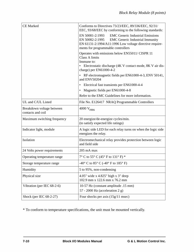
Block Relay Module (8 points)
* To conform to temperature specifications, the unit must be mounted vertically.
CE Marked Conforms to Directives 73/23/EEC, 89/336/EEC, 92/31/EEC, 93/68/EEC by conforming to the following standards:EN 50081-2:1993 EMC Generic Industrial EmissionsEN 50082-2:1995 EMC Generic Industrial ImmunityEN 61131-2:1994/A11:1996 Low voltage directive require-ments for programmable controllersOperates with emissions below EN55011/ CISPR 11Class A limitsImmune to:• Electrostatic discharge (4K V contact mode, 8K V air dis-charge) per EN61000-4-2• RF electromagnetic fields per EN61000-4-3, ENV 50141, and ENV50204• Electrical fast transients per EN61000-4-4 • Magnetic fields per EN61000-4-8Refer to the EMC Guidelines for more information.
UL and C/UL Listed File No. E126417 NRAQ Programmable Controllers
Breakdown voltage betweencontacts and coil
4000 Vrms
Maximum switching frequency 20 energize/de-energize cycles/min.(to satisfy expected life ratings)
Indicator light, module A logic side LED for each relay turns on when the logic side energizes the relay.
Isolation Electromechanical relay provides protection between logic and field side
24 Volts power requirements 205 mA max
Operating temperature range 7° C to 55° C (45° F to 131° F) *
Storage temperature range -40° C to 85° C (-40° F to 185° F)
Humidity 5 to 95%, non-condensing
Physical size 4.05" wide x 4.825" high x 3" deep 102.9 mm x 122.6 mm x 76.2 mm
Vibration (per IEC 68-2-6) 10-57 Hz (constant amplitude .15 mm)57 - 2000 Hz (acceleration 2 g)
Shock (per IEC 68-2-27) Four shocks per axis (15g/11 msec)
7-10 Block I/O Modules Manual G & L Motion Control Inc.

Block Input 120V AC Module (8 points)
8 Block Input 120V AC Module (8 points)
8.1 IntroductionThe input 120V AC module converts AC signals from 8 devices into logic levels that the CPU can use. Each signal is converted into a corresponding logic 1 or 0. An “on” signal is nominally 120 VAC, but can be any level between 79 and 132 volts. An “off” signal is any level below 20 VAC. The wiring configurations may be sink or source.
8 LEDs in the upper section of the module indicate the logic state of each input. The DIAG LED goes on briefly while the diagnostic tests are running.
Figure 8-1 Block Input 120V AC Module (8 Point)
CommunicationsReceive/Transmit
Connector
ScrewTerminal
INPUT 120V AC
G&L Motion Control
IN OUT CONF PWR
Cover(shown open)
Communication/Status LEDs
LEDsInput Status
G & L Motion Control Inc. Block I/O Modules Manual 8-1

Block Input 120V AC Module (8 points)
8.2 Connections A screw terminal is provided for each input and for power connections. The inputs are optically isolated and separated into two groups of four. The external devices in each group must use the same power source, and be wired in the same configuration “sink source”. If an external device supplies current to the module it is a source, if it draws from the module it is a sink.
The external pin connections are shown in Figure 8-2.
The power to operate the module are brought in through pins 12 and 23, +24 volt and 24 volt ground, respectively. Pin 24 Chassis ground need not be connected if block is DIN rail mounted (see Note below).
Figure 8-2 Screw Terminal Connection Assignments
NOTE
To conform to CE requirements for a positive earth connection, con-nect a 6 inch (or less) #14 AWG (2 mm wire) from the chassis pin toearth.
ACSSI ACIN 1 ACIN2 ACIN 3 AC IN 4 ACSS2 ACIN5
Chassis
1 2 3 4 5 6 7 8 9 10 11 12
13 14 15 16 17 18 19 20 21 22 23 24
GND
ACIN6 ACIN7 ACIN8
24 COM
+ 24 V
8-2 Block I/O Modules Manual G & L Motion Control Inc.
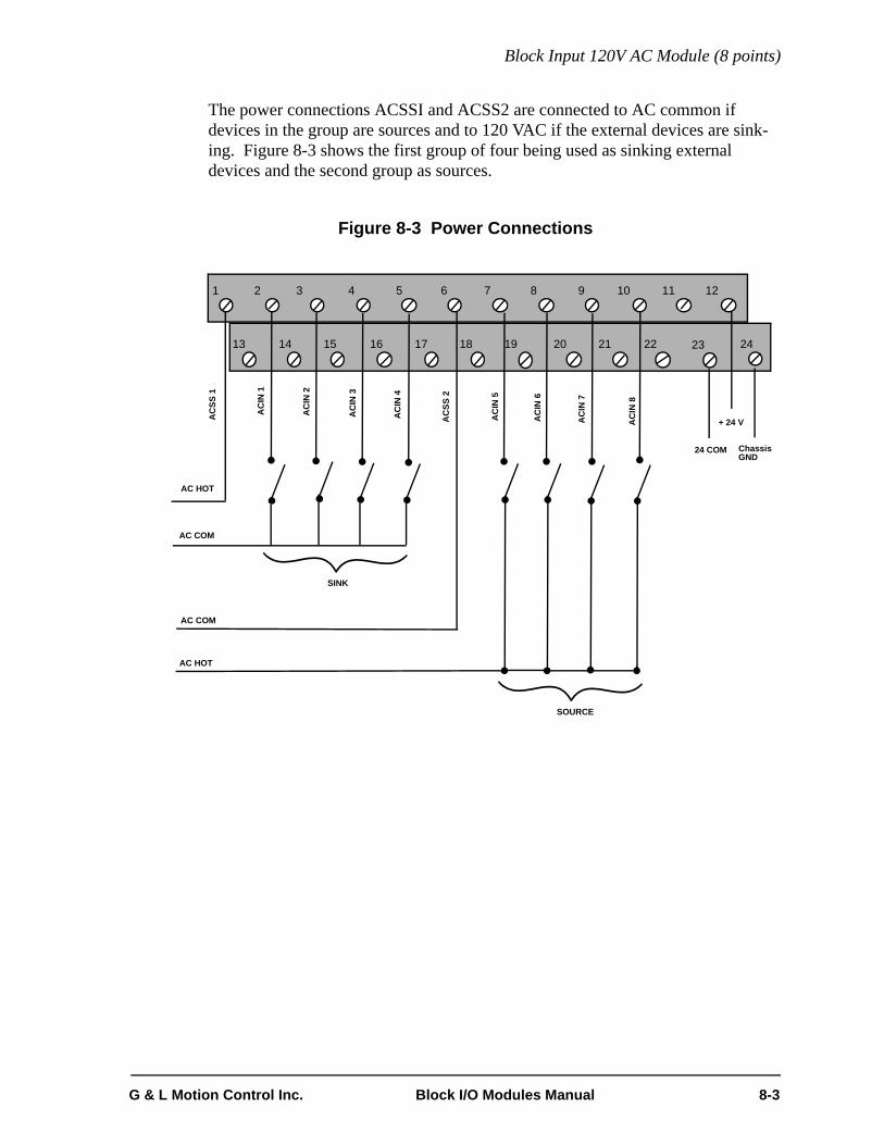
Block Input 120V AC Module (8 points)
The power connections ACSSI and ACSS2 are connected to AC common if devices in the group are sources and to 120 VAC if the external devices are sink-ing. Figure 8-3 shows the first group of four being used as sinking external devices and the second group as sources.
Figure 8-3 Power Connections
1 2 3 4 5 6 7 8 9 10 11 12
13 14 15 16 17 18 19 20 21 22 23 24
ChassisGND
24 COM
+ 24 V
AC HOT
AC COM
AC
IN 1
AC
IN 2
AC
IN 3
AC
IN 4
AC
SS 2
AC
SS 1
AC
IN 5
SINK
AC COM
AC
IN 6
AC
IN 7
AC
IN 8
AC HOT
SOURCE
G & L Motion Control Inc. Block I/O Modules Manual 8-3

Block Input 120V AC Module (8 points)
8.2.1 Communications Connections
There are two 5-pin communications connectors and four logic LEDs on the top of the block I/O module as shown in Figure 8-4.
Figure 8-4 Pinouts for Communication Connectors
8.2.1.1 LEDs
LED Color State DefinitionDATA IN Yellow FAINT Data being passed through the block
moduleBRIGHT or OFF
No activity through the block module
DATA OUT
Yellow FAINT Data is being passed through the block module
BRIGHT or OFF
No activity through the block module
CONFG Green ON Communication established with this block I/O module
OFF Communication not establishedPWR Green ON Internal +5V logic power supply OK
OFF No external 24V applied or internal 5V logic supply not OK
CommunicationsReceive/Transmit
In (from CPU) Out (to next block I/O module)
12345 12345Pin # Pin #
Rec
eive
r +(tw
iste
d pa
ir in
put)
Rec
eive
r -(tw
iste
d pa
ir in
put)
Shie
ld
Driv
er -
Driv
er +
(twis
ted
pair
outp
ut)
(twis
ted
pair
outp
ut)
Driv
er +
(twis
ted
pair
outp
ut)
Driv
er -
(twis
ted
pair
outp
ut)
Shie
ld
Rec
eive
r -(tw
iste
d pa
ir in
put)
Rec
eive
r +(tw
iste
d pa
ir in
put)
G&L Motion Control
IN OUT CONF PWR
8-4 Block I/O Modules Manual G & L Motion Control Inc.

Block Input 120V AC Module (8 points)
8.3 Theory of OperationEach input is guaranteed “on” between 79 and 132 VAC and guaranteed “off” between 0 and 20 VAC. Its on/off state is converted to a corresponding logic 1 or 0. This logic state is transmitted through the system bus to the CPU module, where the processor uses it as data in the ladder program. The logic side of the input is optically isolated from the field side.
An LED in the upper section of the module indicates the logic state of each input. The four LEDs representing each group are in a horizontal row. If you need to know the voltage at the field side, use a voltmeter on the terminal screws.
Figure 8-5 shows the input characteristics of the module compared to IEC standards.
The shaded blocks show the limits specified by the IEC, and the lines show the maximum and minimum V/I of the inputs in this module. This voltage/current curve in this graph shows that the AC input module is well within the IEC Type 1 limits.
Figure 8-5 Input Characteristics Compared to IEC Standards
U in Volts
UHMAX 132
UNOM 120125
“ON” REGION100
UHMIN 79(UTMAX) 75
20 25
1 2 4 6 8 10 12 14 15ITMIN IHMIN INPUT CURRENT
I inmAMPS
TRANSITION REGION
“OFF” REGION
IMAX
(UTMIN )ULMAX
INPU
T VO
LTA
GE
MIN MAX
50
0
G & L Motion Control Inc. Block I/O Modules Manual 8-5

Block Input 120V AC Module (8 points)
IMPORTANT
Switching devices can sometimes have a leakage current that exceedsthe ITmin (current allowed when off) of an input module. In order touse such a device, an impedance (typically, a resistor) needs to beused in parallel with the input. For example, some of the newer proximity switches use two wires in-stead of three. The third wire was used for a power or ground line.Without the third wire, the switch is easier to install. However, it re-quires more leakage current in the off state to power its internal cir-cuitry. As a conservative estimate, use the following formula to calculate anexternal resistance value. It keeps the input voltage at or below 12Vwhen the switching device is in the “off” state.
If the switch leakage specification ≤ 1.7 mA, then:
Use a 16 K Ω, 2W or any lower resistance and higher wattage resistor.Be sure that the wattage is adequate for the resistor remembering that:
It would be acceptable to use a .15 µF (or greater) capacitor rated for120V AC. The advantage of the capacitor is minimal power dissipa-tion.
12VSwitch Leakage 1mA–-------------------------------------------------------- R≥
12V1.7 1mA–------------------------- 17.1KΩ≥
PVrms
2
R-----------=
Xc 12πfC-------------=
8-6 Block I/O Modules Manual G & L Motion Control Inc.

Block Input 120V AC Module (8 points)
8.4 Specification Table
Characteristic Block Input 120V AC Module
Function Monitors on/off states from up to 8 AC voltage inputs
Part number M.1017.4298
Field side connector Two 12 pin connectors, screw terminals
Input signals Nominal 120 VAC on, 0 VAC off, conforming to IEC Type 1 inputs per IEC 1131-2 (two groups of four inputs)
UH Max (max. allowed voltage) 132 VAC
IH Max (max. current @ 132 VAC) 8.7 mA
UL Min 0 V
Guaranteed on 79 VAC
IH Min (min. current @ UH Min) 4.6 mA
Guaranteed off 20 VAC
IT Min (current allowed when off) 1 mA
Frequency 50/60 Hz ± 5%
Time delay on, max. 14 ms
Time delay off, max. 20 ms
Protection of logic circuits Optical isolation between the logic and field sides, 1780 VAC
Field side power dissipation, worst case 9.2 W
Module power requirements 45 mA from an external 24V DC supply (20 to 30V DC range)NOTE: 2.5A, 250 microsecond inrush at power on
G & L Motion Control Inc. Block I/O Modules Manual 8-7

Block Input 120V AC Module (8 points)
CE Marked Conforms to Directives 73/23/EEC, 89/336/EEC, 92/31/EEC, 93/68/EEC by conforming to the following stan-dards:EN 50081-2:1993 EMC Generic Industrial EmissionsEN 50082-2:1995 EMC Generic Industrial ImmunityEN 61131-2:1994/A11:1996 Low voltage directive requirements for programmable controllersOperates with emissions below EN55011/ CISPR 11Class A limitsImmune to:• Electrostatic discharge (4K V contact mode, 8K V air discharge) per EN61000-4-2• RF electromagnetic fields per EN61000-4-3, ENV 50141, and ENV50204• Electrical fast transients per EN61000-4-4 • Magnetic fields per EN61000-4-8Refer to the EMC Guidelines for more information.
UL and C/UL Listed File No. E126417 NRAQ Programmable Controllers
Operating temperature range 7° C to 55° C (45° F to 131° F) *
Storage temperature range -40° C to 85° C (-40° F to 185° F)
Humidity 5 to 95%, non-condensing
Physical size 4.05" wide x 4.825" high x 3" deep 102.9 mm x 122.6 mm x 76.2 mm
Vibration (per IEC 68-2-6) 10-57 Hz (constant amplitude .15 mm)57 - 2000 Hz (acceleration 2 g)
Shock (per IEC 68-2-27) Four shocks per axis (15g/11 msec)
8-8 Block I/O Modules Manual G & L Motion Control Inc.

Block Input Resolver Module (6 channel)
9 Block Input Resolver Module (6 channel)
9.1 IntroductionThe block input resolver module can interface to 6 independent resolvers (or equivalent transducers). Feedback information from the resolvers is used to update the on-board memory. The position of each resolver can be read at any time by the PiC.
The module generates two sine waves (RPO and QPO) 90° out of phase with each other and each channel receives a signal whose phase represents the angular position of the resolver. The resolution of the angular position is 4000 counts per revolution or 0.09 degrees.
Figure 9-1 Block Input Resolver Module (6 Channel)
CommunicationsReceive/Transmit
Connector
ScrewTerminal
INPUT RESOLVER
G&L Motion Control
IN OUT CONF PWR
Cover(shown open)
Communication/Status LEDs
LEDsFeedback OK
G & L Motion Control Inc. Block I/O Modules Manual 9-1

Block Input Resolver Module (6 channel)
9.2 Connections Figure Figure 9-2 shows the screw terminal connections for the block input resolver module.
Figure 9-2 Connections for the Block Input Resolver Terminals
To connect six resolvers to the block resolver module, a user-supplied external terminal block must be used.
Each resolver has three signal pairs. The signals and where they are connected are listed below.
All signals from the resolvers must come to the screw terminal connectors (either on the block resolver module or on the terminal block) through shielded twisted pair wires. These wires must be protected against electrical noise because of the speed and/or voltage levels of the signals transmitted through them. The maximum length of the twisted pair wire from the resolver to the terminal block is 100 feet.
Signal pairs to resolver Connection
RPO and /shield To terminal block
QPO and /shield To terminal block
Signal pair from resolver Connection
FDBK and /shield To block input resolver module
RPO
QPO
RPO GND SHIELD FDBK1+ FDBK1- FDBK2+ FDBK2- 24VFDBK3+
QPO GND FDBK4+ FDBK4- FDBK5+ FDBK5- FDBK6+ FDBK6- 0V Chassis
1 2 3 4 5 6 7 8 9 10 11 12
13 14 15 16 17 18 19 20 21 22 23 24
SHIELD SHIELD
SHIELDSHIELD
FDBK3-
9-2 Block I/O Modules Manual G & L Motion Control Inc.

Block Input Resolver Module (6 channel)
The feedback from each resolver is brought back to the appropriate feedback channel connections on the block resolver module. The module has five screw connections for terminating the feedback shields. All are connected inside the module so they are the same point electrically. If all six resolvers are connected, some of the feedback shields will have to be doubled up on the shield connections.
The shields from the RPO and QPO signals are terminated on shield screw connections on the terminal block. The shield at the device end of the cable is not connected.
Figure 9-3 shows how to wire a terminal block and the first resolver. With the terminal block shown, the RPO, QPO, and outputs from the module are each connected to the terminal block. Each is then jumpered so that there are three signals of each type available for the six resolvers (RPO1, RPO2,... QPO1, QPO2,... , ,... etc.).
To connect six resolvers on this terminal block, two connections would be made to the same screw terminal. 18 AWG wire is recommended for these connections. The maximum wire length between the block input resolver module and the terminal block is 6 feet. The feedback signal from the resolver and its shield are wired directly to the module, not the terminal block.
G & L Motion Control Inc. Block I/O Modules Manual 9-3

Block Input Resolver Module (6 channel)
Figure 9-3 Connecting Resolver, Terminal Block, and Module
NOTE: If the count direction is incorrect after making the connections (i.e. clock-wise rotation is counting down when it should be counting up), swap S1 with S3 or S2 with S4.
+24V DCDC Com
To SPG
+24V0V
Power Supply
RPO
QPO
RPO
GN
D
SHIE
LD
FDB
K1+
FDB
K1-
FDB
K2+
FDB
K2-
FDB
K3+
QPO
GN
D
FDB
K4+
FDB
K4-
FDB
K5+
FDB
K5-
FDB
K6+
FDB
K6-
Cha
ssis
1 2 3 4 5 6 7 8 9 10 11 12
13 14 15 16 17 18 19 20 21 22 23 24
SHIE
LD
SHIE
LD
SHIE
LD
SHIE
LD
FDB
K3-
Block Input Resolver Module Screw Terminals
External Terminal Block
(R1)
FD
BK
+
(R2)
FD
BK
-
(S1)
RPO
(S3)
RPO
GN
D
(S2)
QPO
(S4)
QPO
GN
D
Resolver 1
Color KeyR1 Red/WhiteR2 Yellow/WhiteS1 RedS3 BlackS2 YellowS4 Blue
Make appropriate connections for remaining resolvers.
Resolver 2 Resolver 3 Resolver 4 Resolver 5 Resolver 6
9-4 Block I/O Modules Manual G & L Motion Control Inc.

Block Input Resolver Module (6 channel)
9.2.1 Adding an External Potentiometer
External digitizing potentiometers can be connected to the block input resolver module. This can produce a total count deviation of 1000 from full clockwise to full counter-clockwise. Count values will be in the approximate range of 2000 to 3000. Count values will vary from module to module (for example, 2137 to 3137). Therefore, a reference to the value in the full clockwise or full counter-clockwise position should be performed. Figure 9-4 illustrates one potentiometer connected to the block input resolver module through the external terminal strip.
Figure 9-4 Potentiometer Connected to the Block Input Resolver
+24V DCDC Com
To SPG
+24V0V
Power Supply
RPO
QPO
RPO
GN
D
SHIE
LD
FDB
K1+
FDB
K1-
FDB
K2+
FDB
K2-
FDB
K3+
QPO
GN
D
FDB
K4+
FDB
K4-
FDB
K5+
FDB
K5-
FDB
K6+
FDB
K6-
Cha
ssis
1 2 3 4 5 6 7 8 9 10 11 12
13 14 15 16 17 18 19 20 21 22 23 24
SHIE
LD
SHIE
LD
SHIE
LD
SHIE
LD
FDB
K3-
Block Input Resolver Module Screw Terminals
External Terminal Block
QPO RPO
CW
Potentiometer Connections
NC
G & L Motion Control Inc. Block I/O Modules Manual 9-5

Block Input Resolver Module (6 channel)
9.2.2 Communications Connections
There are two 5-pin communications connectors and four logic LEDs on the top of the block I/O module as shown in Figure 9-5.
Figure 9-5 Pinouts for Communication Connectors
9.2.2.1 LEDs
LED Color State DefinitionDATA IN Yellow FAINT Data being passed through the block
moduleBRIGHT or OFF
No activity through the block module
DATA OUT Yellow FAINT Data is being passed through the block module
BRIGHT or OFF
No activity through the block module
CONFG Green ON Communication established with this block I/O module
OFF Communication not establishedPWR Green ON Internal +5V logic power supply OK
OFF No external 24V applied or internal 5V logic supply not OK
CommunicationsReceive/Transmit
In (from CPU) Out (to next block I/O module)
12345 12345Pin # Pin #
Rec
eive
r +(tw
iste
d pa
ir in
put)
Rec
eive
r -(tw
iste
d pa
ir in
put)
Shie
ld
Driv
er -
Driv
er +
(twis
ted
pair
outp
ut)
(twis
ted
pair
outp
ut)
Driv
er +
(twis
ted
pair
outp
ut)
Driv
er -
(twis
ted
pair
outp
ut)
Shie
ld
Rec
eive
r -(tw
iste
d pa
ir in
put)
Rec
eive
r +(tw
iste
d pa
ir in
put)
G&L Motion Control
IN OUT CONF PWR
9-6 Block I/O Modules Manual G & L Motion Control Inc.
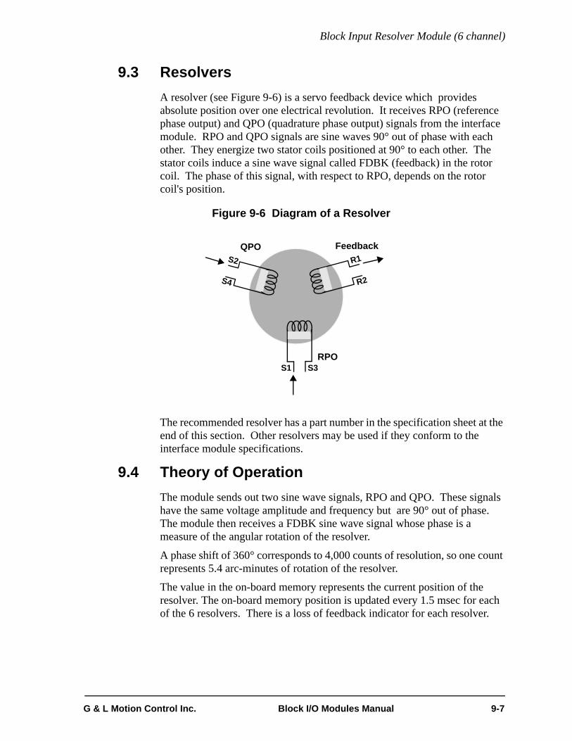
Block Input Resolver Module (6 channel)
9.3 ResolversA resolver (see Figure 9-6) is a servo feedback device which provides absolute position over one electrical revolution. It receives RPO (reference phase output) and QPO (quadrature phase output) signals from the interface module. RPO and QPO signals are sine waves 90° out of phase with each other. They energize two stator coils positioned at 90° to each other. The stator coils induce a sine wave signal called FDBK (feedback) in the rotor coil. The phase of this signal, with respect to RPO, depends on the rotor coil's position.
Figure 9-6 Diagram of a Resolver
The recommended resolver has a part number in the specification sheet at the end of this section. Other resolvers may be used if they conform to the interface module specifications.
9.4 Theory of OperationThe module sends out two sine wave signals, RPO and QPO. These signals have the same voltage amplitude and frequency but are 90° out of phase. The module then receives a FDBK sine wave signal whose phase is a measure of the angular rotation of the resolver.
A phase shift of 360° corresponds to 4,000 counts of resolution, so one count represents 5.4 arc-minutes of rotation of the resolver.
The value in the on-board memory represents the current position of the resolver. The on-board memory position is updated every 1.5 msec for each of the 6 resolvers. There is a loss of feedback indicator for each resolver.
QPO
RPO
Feedback
S1
S2
S3
S4
R1
R2
G & L Motion Control Inc. Block I/O Modules Manual 9-7

Block Input Resolver Module (6 channel)
9.5 Specification Table
Characteristic Block Input Resolver (6 ch) Module Specifications
Function Measures the position of a transducer that accepts a 2-phase quadrature excitation, such as a resolver or potenti-ometer
Part number M.1017.3138
Field side connector 24 pin card edge connector, screw terminals
Excitation method 2-phase quadrature for control transformer type of resolver
RPO and QPO outputs
Frequency 4KHz
Output voltage 15 VP-P (5.3VRMS)
Current per output channel, max. 100 mA
Resolver transformer ratio .5 to 1.0
Resolution, resolver 4000 Feedback Units (FUs) per electrical revolution
Resolution, potentiometer 1000 Feedback Units (FUs) per electrical revolution
Accuracy at constant temperature ± 12 arc minutes
Accuracy over temperature range ± 5.4 arc minutes /10°F
Velocity, max. 15000 electrical RPM (1M FU/Sec.)
Cable length, max. 6 ft. from module to terminal block (18 AWG)100 ft. from terminal block to resolvers (twisted pair)
Stored position value range 0-3999
Logic side LEDs, module status Data In LEDData Out LEDConfigured LEDPower LED
Module power requirements 200 mA from an external 24V DC supply (20 to 30V DC range)NOTE: 2.5A, 250 microsecond inrush at power on
Recommended resolver G&L Motion Control part number M.1200.0399Harowe 11BRW 300-F-1/10
Other suggested resolvers Clifton 11BHW-0IE/A004Kearfott CR410959
9-8 Block I/O Modules Manual G & L Motion Control Inc.

Block Input Resolver Module (6 channel)
CE Marked Conforms to Directives 73/23/EEC, 89/336/EEC, 92/31/EEC, 93/68/EEC by conforming to the following stan-dards:EN 50081-2:1993 EMC Generic Industrial EmissionsEN 50082-2:1995 EMC Generic Industrial ImmunityEN 61131-2:1994/A11:1996 Low voltage directive requirements for programmable controllersOperates with emissions below EN55011/ CISPR 11Class A limitsImmune to:• Electrostatic discharge (4K V contact mode, 8K V air discharge) per EN61000-4-2• RF electromagnetic fields per EN61000-4-3, ENV 50141, and ENV50204• Electrical fast transients per EN61000-4-4 • Magnetic fields per EN61000-4-8Refer to the EMC Guidelines for more information.
UL and C/UL Listed File No. E126417 NRAQ Programmable Controllers
Operating temperature range 7° C to 55° C (45° F to 131° F)
Storage temperature range -40° C to 85° C (-40° F to 185° F)
Humidity 5 to 95%, non-condensing
Physical size 4.05" wide x 4.825" high x 3" deep 102.9 mm x 122.6 mm x 76.2 mm
Vibration (per IEC 68-2-6) 10-57 Hz (constant amplitude .15 mm)57 - 2000 Hz (acceleration 2 g)
Shock (per IEC 68-2-27) Four shocks per axis (15g/11 msec)
G & L Motion Control Inc. Block I/O Modules Manual 9-9

Block Input Resolver Module (6 channel)
THIS PAGE INTENTIONALLY BLANK
9-10 Block I/O Modules Manual G & L Motion Control Inc.

Block Output Stepper/Input Encoder/ Input 24V DC Module (2/2/2 Channel)
10 Block Output Stepper/Input Encoder/Input 24V DC Module (2/2/2 Channel)
10.1 IntroductionThis block I/O module provides the following:
• Two output stepper channels
• Two input encoder channels
• Two 24V DC inputs
Figure 10-1 Block Output Stepper/Input Encoder/Input 24V DC Module (2/2/2 Ch)
CommunicationsReceive/Transmit
Connector
ScrewTerminal
OUTPUT STEPPER
G&L Motion Control
IN OUT CONF PWR
Cover(shown open)
INPUT ENCODER
Communication/Status LEDs
Input StatusLEDs
G & L Motion Control Inc. Block I/O Modules Manual 10-1

Block Output Stepper/Input Encoder/ Input 24V DC Module (2/2/2
10.1.1 Output Stepper
Each stepper channel can control one stepper drive. The maximum step rate is one million steps per second.
An external power supply (4.5 VDC to 20 VDC) or the internal +5V DC can be used to power each stepper output. Commands and control data are sent to the module, and status and position information are received from the module, via software.
10.1.2 Input Encoder
Each encoder channel can interface to one independent quadrature incremental encoder or equivalent device. Information from each encoder is used to update a separate position counter and latch within the module.
For each channel, a 24-bit counter is incremented or decremented based on signals it receives from the A, A, B, and B outputs of a quadrature encoder. The counter value can be latched (stored) if the module receives an I or I output signal from the encoder.
10.1.3 Input 24V DC
The 24V DC inputs convert DC signals from devices into logic levels that the CPU can use. Each signal is converted into a corresponding logic 1 or 0 which is transmitted through the communication interface to the CPU module. An “on” signal is nominally 24V DC, but can be any level between 15V and 30V. An “off” signal is any level below 5V. The wiring configurations may be sink or source. Two field side LEDs indicate the state of the inputs.
10-2 Block I/O Modules Manual G & L Motion Control Inc.

Block Output Stepper/Input Encoder/ Input 24V DC Module (2/2/2 Channel)
10.2 Connections A screw terminal connector is provided for each connection as shown in Figure 10-2. Use up to 14 AWG for field side wiring.
Figure 10-2 Screw Terminal Connector Assignments
10.2.1 Stepper Connections
For the stepper outputs, the DC power supply can be provided by any combination of the following:
• The stepper drive
• An external DC supply daisy-chained to both outputs
• Separate external DC supplies for each output
• The +5V supply available on the block module
An external DC supply that powers the output signals should have a wire connected from its 0V (COMMON) terminal directly to the controller’s single point ground. The power disconnect switch should be the same one used for the system. The following connections for one output are illustrated in Figure 10-3.
ST1+VIN to the +V terminal of the external power supply or the +5V OUT terminal of the internal power supply
ST1 STEP/CW to the step or clockwise input of the drive
ST1 DIR/CCW to direction or counterclockwise input of the drive
ST1 +VINCOM to the 0V terminal of the external power supplyNOTE: When the drive inputs are optically iso-lated, tie the 0V of the external power supply to SPG or to pin 35.
SHIELD All shield pins on the module are connected to each other internally and to the chassis screw terminal and the metal strip on the base of the module.
1 3 4 5 6 7 8 9 10 11 12 13 14 15 16 17 182
19 21 22 23 24 25 26 27 28 29 30 31 32 33 34 35 3620
CH
ASS
IS
24V
0V
24V
EN
C1A
+5V
OU
T
+5V
OU
T
DC
IN1
DC
IN 2
SH
IELD
+5V
OU
TCO
M
+5V
OU
TCO
M
0V
DC
IN S
S
SH
IELD
+5V
OU
T
+5V
OU
T
EN
C1A
EN
C2A
EN
C2A
EN
C1B
EN
C1B
EN
C2B
EN
C2B
EN
C1I
ND
EX
EN
C1I
ND
EX
EN
C2
IND
EX
EN
C2
IND
EX
ST1
STE
P/C
W
ST2
STE
P/C
W
ST1
DIR
/CC
W
ST2
DIR
/CC
W
ST1
+VI
NC
OM
ST2
+VI
NC
OM
ST1
+V
IN
ST2
+VI
N
G & L Motion Control Inc. Block I/O Modules Manual 10-3

Block Output Stepper/Input Encoder/ Input 24V DC Module (2/2/2
Figure 10-3 Connections for One Stepper Output
WARNING
The +5V OUT internal power supply available at the terminal screwsis also used by the module’s logic circuitry. If problems are encoun-tered, use an external power supply instead.
1 3 4 5 6 72
19 21 22 2320
+5V
OU
T
SHIE
LD
+5V
OU
TCO
M
ST1
sTE
P/C
W
ST1
DIR
/CC
W
ST1
+V
INC
OM
ST1
+VI
N
Internal CircuitryBlock Module
SPG
CHASSIS (SPG)
V+ 0VExternal
DC Supply
NOTE: As an alternative to anexternal DC power supply,you can use the +5V availableon the block module. See in-sert for wiring.
1 3 4 5 6 72
19 21 22 2320
+5V
OU
T
SHIE
LD
+5VO
UTC
OM
ST1
STE
P/C
W
ST1
DIR
/CC
W
ST1
+VIN
CO
M
ST1
+VI
N
10-4 Block I/O Modules Manual G & L Motion Control Inc.

Block Output Stepper/Input Encoder/ Input 24V DC Module (2/2/2 Channel)
10.2.2 Connecting the Block Module to Stepper Drives
Consult your drive manual regarding the proper connection of an indexer. Four types of drive inputs and the proper connection techniques are shown in Figure 10-4, Figure 10-5, Figure 10-6 and Figure 10-7.
When working with opto-coupler drive inputs, be sure the input diode is protected by a current-limiting resistor as stated in the following important note.
Following the wiring guidelines listed below will increase the reliability of the block module/drive system.
1. Route the wiring from the block module separately from any high current or electrically noisy wiring.
2. Keep the wires connecting the block module to the drive less than 10 feet in length.
3. Shield the wiring from the block module. Tie shields to the block module shield terminal screw and leave the other end of the shield unconnected.
IMPORTANT
There is a limit to the amount of current the input diodeof the drive opto-coupler can withstand. If this currentis exceeded, the device will be destroyed. The block module is capable of sinking considerablymore current than the 15 mA specified. Most driveshaving opto-coupler inputs have a series current-limitresistor sized properly for a +5V external supply. If the drive being used has an opto-coupler input butdoes not have a current-limit resistor or if thecurrent-limit resistor is too small, then one will have tobe added externally. Consult your drive manual for in-formation regarding this topic.
G & L Motion Control Inc. Block I/O Modules Manual 10-5

Block Output Stepper/Input Encoder/ Input 24V DC Module (2/2/2
10.2.2.1 Opto-Coupler Drive Inputs
The inputs for this type of drive will be:
• Step +
• Step -
• Direction +
• Direction -
Make the following connections as shown in Figure 10-4.
Block Module
External Power Supply Drive
ST1 STEP/CW to N/C to Step -
ST1 DIR/CCW to N/C to Direction -
ST1 +VIN to +V to Step + and Direction +
ST1 +VINCOM to 0V to N/C
10-6 Block I/O Modules Manual G & L Motion Control Inc.

Block Output Stepper/Input Encoder/ Input 24V DC Module (2/2/2 Channel)
Figure 10-4 Block Module (Stepper) Connections to Opto-Coupler Drive Inputs
10.2.2.2 Opto-Coupler with Common Source DriveInputs
The inputs for this type of drive will be:
• Opto power input
• Step
• Direction
Make the following connections as shown in Figure 10-5:
Block Module
External Power Supply Drive
ST1 STEP/CW to N/C to Step
ST1 DIR/CCW to N/C to Direction
ST1 +VIN to +V to Opto power input
ST1 +VINCOM to 0V to N/C
1 3 4 5 6 72
19 21 22 2320
+5V
OU
T
SHIE
LD
+5V
OU
TCO
M
ST1
STE
P/C
W
ST1
DIR
/CC
W
ST1
+VI
NC
OM
ST1
+VIN
SPG
V+ 0V
ExternalDC Supply
Block Module
Step- Dir+Step+ Dir-
220
ohm
Drive with opto-coupler inputs
220
ohm
+5V
G & L Motion Control Inc. Block I/O Modules Manual 10-7
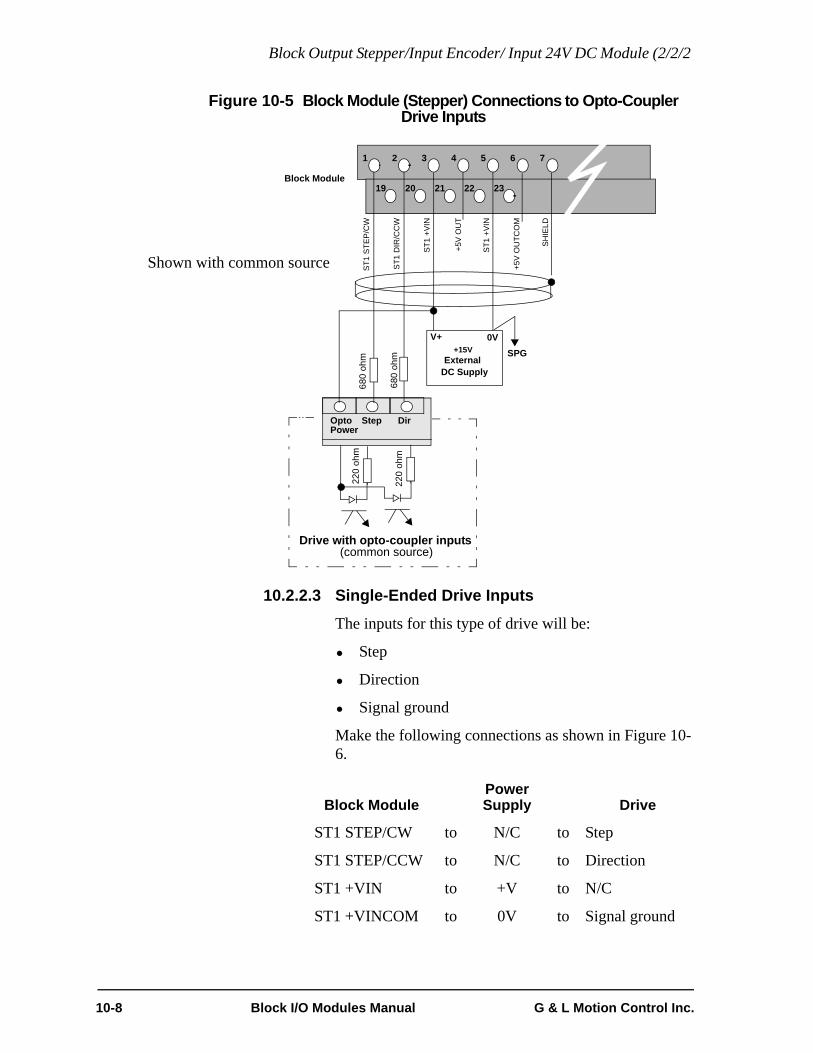
Block Output Stepper/Input Encoder/ Input 24V DC Module (2/2/2
Figure 10-5 Block Module (Stepper) Connections to Opto-CouplerDrive Inputs
10.2.2.3 Single-Ended Drive Inputs
The inputs for this type of drive will be:
• Step
• Direction
• Signal ground
Make the following connections as shown in Figure 10-6.
Block ModulePower Supply Drive
ST1 STEP/CW to N/C to Step
ST1 STEP/CCW to N/C to Direction
ST1 +VIN to +V to N/C
ST1 +VINCOM to 0V to Signal ground
1 3 4 5 6 72
19 21 22 2320
+5V
OU
T
SHIE
LD
+5V
OU
TCO
M
ST1
STE
P/C
W
ST1
DIR
/CC
W
ST1
+VIN
ST1
+VIN
SPG
V+ 0V
ExternalDC Supply
Block Module
Step DirOpto
220
ohm
Drive with opto-coupler inputs
220
ohm
(common source)
Power
680
ohm
680
ohm
+15V
Shown with common source
10-8 Block I/O Modules Manual G & L Motion Control Inc.

Block Output Stepper/Input Encoder/ Input 24V DC Module (2/2/2 Channel)
Figure 10-6 Block Module (Stepper) Connections to Single-EndedDrive Inputs
If the pull-up resistors internal to the drive are inadequate, you may need to add external pull-up resistors. Install them as close as possible to the drive.
1 3 4 5 6 72
19 21 22 2320
+5V
OU
T
SH
IELD
+5V
OU
TCO
M
ST1
STE
P/C
W
ST1
DIR
/CC
W
ST1
+VIN
CO
M
ST1
+VIN
SPG
V+ 0V
ExternalDC Supply
Block Module
Step Dir Signal
Drive with single-ended inputs
1K ohm
Ground
+5V1K ohm+5V
+5V
G & L Motion Control Inc. Block I/O Modules Manual 10-9

Block Output Stepper/Input Encoder/ Input 24V DC Module (2/2/2
10.2.2.4 Differential Drive Inputs
The inputs for this type of drive will be:
• Step +
• Step -
• Direction +
• Direction -
• Signal ground
Make the following connections as shown in Figure 10-7.
Block ModulePower Supply Drive
ST1 STEP/CW to N/C to Step +
ST1 DIR/CCW to N/C to Direction +
ST1 +VIN to +V to N/C
ST1 +VINCOM to 0V to Signal ground
10-10 Block I/O Modules Manual G & L Motion Control Inc.

Block Output Stepper/Input Encoder/ Input 24V DC Module (2/2/2 Channel)
Figure 10-7 Block Module (Stepper) Connectionsto Differential Drive Inputs
1 3 4 5 6 72
19 21 22 2320
+5V
OU
T
SH
IELD
+5V
OU
TCO
M
ST1
STE
P/C
W
ST1
DIR
/CC
W
ST1
+VIN
CO
M
ST1
+V
IN
SPG
V+ 0V
ExternalDC Supply
Block Module
Drive with differential inputs
+5V
+ -
Step- Dir+Step+ Dir- SignalGround
+ -
+5V+5V
+5V
+5V
NOTE: If the Step - and Direction -are not biased to one half theexternal supply by the drive,external voltage dividers willbe required. Install the voltagedividers as close to the driveas possible.
G & L Motion Control Inc. Block I/O Modules Manual 10-11

Block Output Stepper/Input Encoder/ Input 24V DC Module (2/2/2
10.2.3 Block Module Encoder Connections
All signals to the encoder inputs of the block module must come to its screw terminal connector through shielded twisted pair wires. These wires must be protected against electrical noise because of the speed and/or voltage levels of the signals transmitted through them. See the discussion on “Preventing electrical noise in data lines” in the Hardware chapter.
Each encoder module channel has three signal pairs, each of which has two screw terminal connections. The signal pairs are:
• encoder input A and A
• encoder input B and B
• index input and index
In addition the module has screw connections for terminating the shields. All shield pins on the module are connected to each other internally and to the chassis screw terminal and the metal strip on the base of the module.
Figure 10-8 shows the assignments for all the screw terminal connections on the module. To make the diagram more readable, the shielded twisted pair wires are shown with transparent shields.
IMPORTANT
The power supply to the encoder (or signal source device)must have its common connected to the SPG.
WARNING
The +5V OUT internal power supply available at the ter-minal screws is also used by the module’s logic circuitry.If problems are encountered, use an external power sup-ply instead.
10-12 Block I/O Modules Manual G & L Motion Control Inc.

Block Output Stepper/Input Encoder/ Input 24V DC Module (2/2/2 Channel)
Figure 10-8 Block Module (Encoder) Connections
A A B BIndexIndex
Encoder 1
6 7 8 9 10 11 12 13 14
24 25 26 27 28 29 30 31 32
EN
C1A
SH
IELD
+5V
OU
TCO
M
+5V
OU
TCO
M
SH
IELD
+5V
OU
T
+5V
OU
T
EN
C1A
EN
C2A
EN
C2A
EN
C1B
EN
C1B
EN
C2B
EN
C2B
EN
C1I
ND
EX
EN
C1I
ND
EX
EN
C2
IND
EX
EN
C2I
ND
EX
A A B BIn
dex
Inde
x
Encoder 2
0V
+V
SPG
Block ModuleScrew Terminals
EncoderPower Supply
4V to 6V DC
0V
+V
SPG
Encoder 2 using external power supply
Encoder 1 using block module +5V for power supply
G & L Motion Control Inc. Block I/O Modules Manual 10-13

Block Output Stepper/Input Encoder/ Input 24V DC Module (2/2/2
10.2.3.1 Encoder Drivers
Acceptable drivers provided by encoder manufacturers include:
The three encoder outputs are paired:
• A and A
• B and B
• index and index
Differential voltage drivers 75183883075114961426LS31
NOTE
Encoders with differential drivers are required.They provide better noise immunity and capabilityfor the module to detect “loss of feedback.” See thesection in the Hardware chapter on “Preventingelectrical noise in data lines” for a comparison be-tween differential and single-ended interfaces.
10-14 Block I/O Modules Manual G & L Motion Control Inc.

Block Output Stepper/Input Encoder/ Input 24V DC Module (2/2/2 Channel)
10.2.4 Block Module DC Input Connections
The external DC supply used to power the input signals should have a wire connected from its 0V (common) terminal directly to the single-point ground used for the system rack. Its power disconnect switch should be the same one used for the system rack. The DC inputs can be set up as sinking or sourcing.
The drawing on the left side of Figure 10-9 shows devices “sinking” current through the DC inputs. The HOT terminal of the power supply must be connected to the module at DCInSS. The drawing on the right side of Figure 10-9 shows devices “sourcing” current through the DC inputs. The COMMON terminal of the power supply must be connected to the module at DCInSS.
Figure 10-9 Sinking or Sourcing Connections for DC Input
10.2.5 Power Connections
An external 24V DC supply must be connected to pins 18 and 35 as shown in Figure 10-9.
15 16 17 18
33 34 35 36
24V
0V
DC
In1
DC
In 2
DC
In S
S
DCPowerSupply
0V +V
Sink Source
15 16 17 18
33 34 35 36
24V
0V
DC
In1
DC
In 2
DC
In S
SDC
PowerSupply
0V +V
ORCommon
Hot
HotCommon
G & L Motion Control Inc. Block I/O Modules Manual 10-15

Block Output Stepper/Input Encoder/ Input 24V DC Module (2/2/2
10.2.6 Communications Connections
There are two 5-pin communications connectors and four logic LEDs on the top of the block I/O module as shown in Figure 10-10 below.
Figure 10-10 Pinouts for Communication Connectors
10.2.6.1 LEDs
LED Color State DefinitionDATA IN Yellow FAINT Data being passed through the block
moduleBRIGHT or OFF
No activity through the block module
DATA OUT
Yellow FAINT Data is being passed through the block module
BRIGHT or OFF
No activity through the block module
CONFG Green ON Communication established with this block I/O module
OFF Communication not establishedPWR Green ON Internal +5V logic power supply OK
OFF No external 24V applied or internal 5V logic supply not OK
CommunicationsReceive/Transmit
In (from CPU) Out (to next block I/O module)
12345 12345Pin # Pin #R
ecei
ver +
(twis
ted
pair
inpu
t)
Rec
eive
r -(tw
iste
d pa
ir in
put)
Shie
ld
Driv
er -
Driv
er +
(twis
ted
pair
outp
ut)
(twis
ted
pair
outp
ut)
Driv
er +
(twis
ted
pair
outp
ut)
Driv
er -
(twis
ted
pair
outp
ut)
Shie
ld
Rec
eive
r -(tw
iste
d pa
ir in
put)
Rec
eive
r +(tw
iste
d pa
ir in
put)
G&L Motion Control
IN OUT CONF PWR
10-16 Block I/O Modules Manual G & L Motion Control Inc.

Block Output Stepper/Input Encoder/ Input 24V DC Module (2/2/2 Channel)
10.3 Theory of Operation
10.3.1 Stepper Theory of Operation
The stepper section of the block module is part of an open loop control system used to position from one to two axes. The diagram in Figure 10-11 illustrates one axis being controlled by the block module. Digital signals from the block module are converted into fixed increments of motion via the stepper drive. This allows the stepper motor to move the load accurately and reliably by following the number of input steps.
Figure 10-11 Open Loop Stepper System
The block module controls the position, velocity, and acceleration of the stepper motor. The number of pulses generated by the block module provides distance information (steps) and the rate of these pulses provides velocity information (steps/sec). The rate of change of the pulse rate provides acceleration/deceleration information (steps/sec/sec).
Commands (acc/dec rates, maximum velocity, reference position, distance, position, and velocity moves) and control data (E-stop, C-stop, start, pause, continue, modes) are sent to the module and status and position information are received from the module via software. Each channel can have up to 500 commands queued up on the module.
The step rate programmed by you for a velocity command (or calculated by the block module during acceleration or deceleration) versus the actual rate output from the block module is defined by the following equation:
where X is the integer quotient of
Refer to the PiCPro Online Help for information on controlling the block module via software.
PiC900CPU
DataTransfer
BlockModule Stepper
DriveLOAD
StepperMotor
ActualRate 10 106×X
--------------------=
10 106×ProgrammedRate-----------------------------------------------
G & L Motion Control Inc. Block I/O Modules Manual 10-17
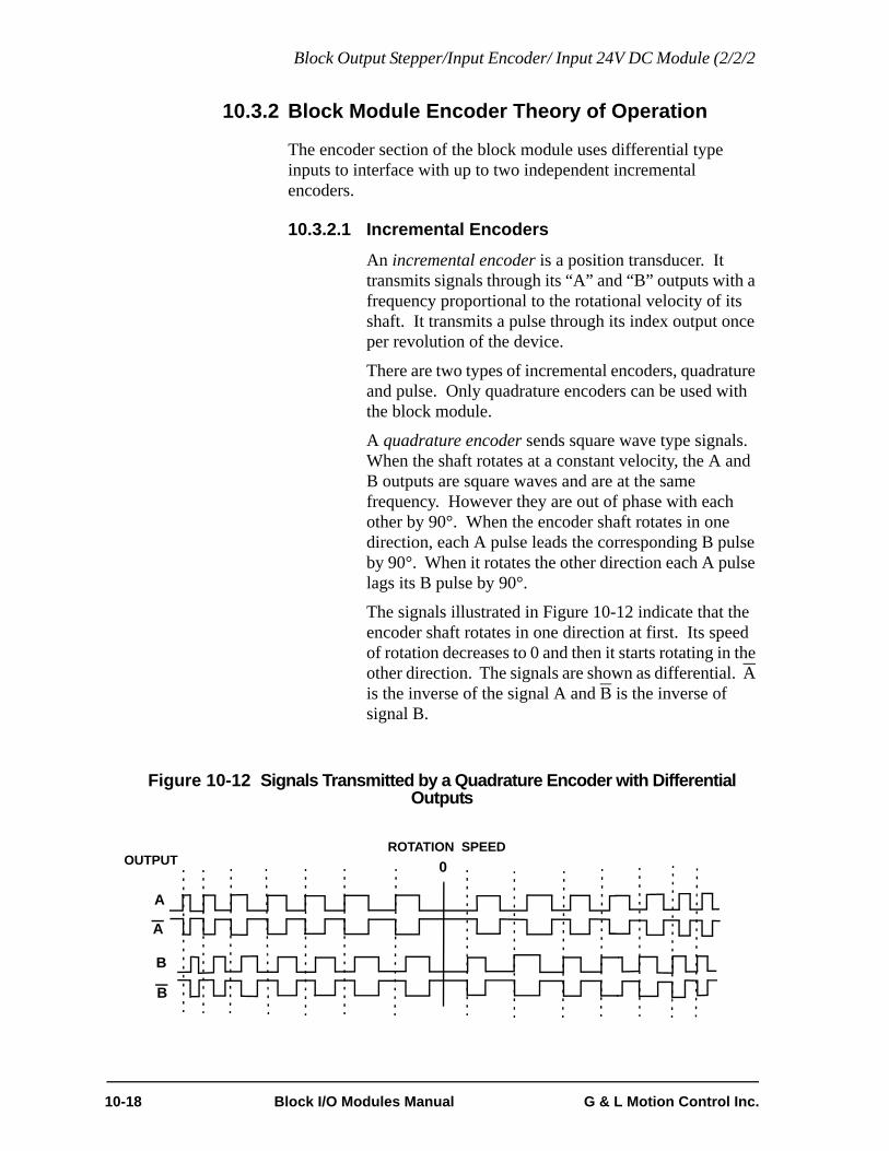
Block Output Stepper/Input Encoder/ Input 24V DC Module (2/2/2
10.3.2 Block Module Encoder Theory of Operation
The encoder section of the block module uses differential type inputs to interface with up to two independent incremental encoders.
10.3.2.1 Incremental Encoders
An incremental encoder is a position transducer. It transmits signals through its “A” and “B” outputs with a frequency proportional to the rotational velocity of its shaft. It transmits a pulse through its index output once per revolution of the device.
There are two types of incremental encoders, quadrature and pulse. Only quadrature encoders can be used with the block module.
A quadrature encoder sends square wave type signals. When the shaft rotates at a constant velocity, the A and B outputs are square waves and are at the same frequency. However they are out of phase with each other by 90°. When the encoder shaft rotates in one direction, each A pulse leads the corresponding B pulse by 90°. When it rotates the other direction each A pulse lags its B pulse by 90°.
The signals illustrated in Figure 10-12 indicate that the encoder shaft rotates in one direction at first. Its speed of rotation decreases to 0 and then it starts rotating in the other direction. The signals are shown as differential. A is the inverse of the signal A and B is the inverse of signal B.
Figure 10-12 Signals Transmitted by a Quadrature Encoder with Differential Outputs
ROTATION SPEED0
A
A
B
B
OUTPUT
10-18 Block I/O Modules Manual G & L Motion Control Inc.

Block Output Stepper/Input Encoder/ Input 24V DC Module (2/2/2 Channel)
Quadrature Type Encoder
The signal at output A or B from the encoder has a frequency that is the product of the resolution of the encoder in pulses (lines) per revolution and the speed of the encoder in revolutions per second.
Thus an encoder that generates 2,000 pulses (lines) per revolution and rotates at 10 revolutions per second generates 20,000 pulses (lines) per second. In a quadrature type encoder, the interface module would supply 80,000 Feedback Units per second.
The maximum input frequency is 250,000 lines per second, which results in 1,000,000 Feedback Units (FUs) per second in the encoder module.
Figure 10-13 Counting Quadrature Pulses
For each encoder channel, there is a 24-bit up/down counter. It is incremented or decremented in accordance with the signals received from the differential quadrature encoder. There is also a 24-bit latch associated with each encoder input channel.
The module can be programmed so that the counter value is “latched” or stored upon receiving an index pulse from the encoder.
B
A
1 2 3 4 5 6 7 8 9 10 11 12 Encoder Count
The module counts positivetransitions at both channel Aand channel B. One quadraturecycle in this case gives4 feedback units.
G & L Motion Control Inc. Block I/O Modules Manual 10-19

Block Output Stepper/Input Encoder/ Input 24V DC Module (2/2/2
10.3.3 DC Input Theory of Operation
Each input is guaranteed “on” at 15 to 30 VDC and guaranteed “off” at 0 to 5 VDC; polarity doesn't matter. Its on/off state is converted to a corresponding logic 1 or 0. This logic state is transmitted through the communication interface to the CPU module, where the processor uses it as data in the ladder program. The logic side of the input is optically isolated from the field side.
The logic state of each input is represented by an LED. If you need to know whether voltage is present at the field side, use a voltmeter on the terminal screws.
The shaded blocks in Figure 10-14 show the limits specified by the IEC. The lines show the maximum and minimum V/I of the inputs in this module. The voltage/current curve in this graph shows that the input module is well within the IEC Type 1 limits.
Figure 10-14 Input Characteristics Compared to IEC Standards
U in VoltsUHMAX 30
UNOM 2425
“ON” REGION
20
UHMIN 15(UTMAX)
10
5
0
-5
.5 2 4 6 8 10 12 14 15ITMIN IHMIN
INPUT CURRENT
I inmAMPS
TRANSITION REGION
“OFF” REGION
IMAX
(UTMIN )ULMAX
INPU
T VO
LTA
GE
MIN MAX
10-20 Block I/O Modules Manual G & L Motion Control Inc.

Block Output Stepper/Input Encoder/ Input 24V DC Module (2/2/2 Channel)
IMPORTANT
Switching devices can sometimes have a leakage current that ex-ceeds the ITmin (current allowed when off) of an input module. In or-der to use such a device, an impedance (typically, a resistor) needs tobe used in parallel with the input.For example, some of the newer proximity switches use two wires in-stead of three. The third wire was used for a power or ground line.Without the third wire, the switch is easier to install. However, it re-quires more leakage current in the off state to power its internal cir-cuitry.As a conservative estimate, use the following formula to calculate anexternal resistance value. It keeps the input voltage at or below 2.4Vwhen the switching device is in the "off" state.
If the switch leakage specification is ≤ 1.7 mA, then:
Use a resistor less than or equal to 2.5 KΩ. Be sure that the wattageis adequate for the resistor when the switching device is in the “on”state remembering that:
2.4VSwitch Leakage 0.75mA–--------------------------------------------------------------- R≥
2.4V1.7 0.75mA–-------------------------------- 2.5KΩ≥
PVON
2
R----------=
G & L Motion Control Inc. Block I/O Modules Manual 10-21

Block Output Stepper/Input Encoder/ Input 24V DC Module (2/2/2
10.4 Specification Table
CharacteristicBlock Output Stepper/Input Encoder/Input 24V DC (2/2/2 ch) specifications
Function Includes two stepper outputs, two encoder inputs and two DC inputs
Part number M.1017.3143
Field side connector Two 18-pin connectors, screw terminals
Logic side LEDs, module status Data In LEDData Out LEDConfigured LEDPower LED
Module power requirements 300 mA from an external 24 VDC supply (20 to 30 VDC range)NOTE: 1.1 A, 250 microsecond inrush at power on
Current output from +5V Out pins 500 mA total available from the module
Operating temperature range 7° C to 55° C (45° F to 131° F)
Storage temperature range -40° C to 85° C (-40° F to 185° F)
Humidity 5 to 95%, non-condensing
CE Marked Conforms to Directives 73/23/EEC, 89/336/EEC, 92/31/EEC, 93/68/EEC by conforming to the following stan-dards:EN 50081-2:1993 EMC Generic Industrial EmissionsEN 50082-2:1995 EMC Generic Industrial ImmunityEN 61131-2:1994/A11:1996 Low voltage directive requirements for programmable controllersOperates with emissions below EN55011/ CISPR 11Class A limitsImmune to:• Electrostatic discharge (4K V contact mode, 8K V air discharge) per EN61000-4-2• RF electromagnetic fields per EN61000-4-3, ENV 50141, and ENV50204• Electrical fast transients per EN61000-4-4 • Magnetic fields per EN61000-4-8Refer to the EMC Guidelines for more information.
UL and C/UL Listed File No. E126417 NRAQ Programmable Controllers
Physical size 4.05" wide x 4.825" high x 3" deep 102.9 mm x 122.6 mm x 76.2 mm
10-22 Block I/O Modules Manual G & L Motion Control Inc.

Block Output Stepper/Input Encoder/ Input 24V DC Module (2/2/2 Channel)
Stepper Section
+V input (from external supply) 4.5 VDC to 20 VDC, 45 mA per connected channel
Step/CW output ratingDirection/CCW output rating
Totem pole, 15 mA sink, 5 mA source
Protection of logic circuits Optical isolation between the logic and field side
Position range ±2,147,352,575 steps
Step rate 0 to 1,000,000 steps/sec
Step rate accuracy
where X is the integer quotient of
Acceleration/deceleration rate 1 to 16,777,215 steps/sec/sec
Reference range ±2,147,352,575 steps
Response to scan loss Pulse output halted
Encoder Section
Encoder (A, B, and index) 2231 Differential Receiver
Guaranteed on, min. 2.5 VDC @ 2.5 mA
Input voltage, max. 7 VDC
Input current, max. 22 mA @ 7 VDC
Signal pulse width, min. .6 µs(600 ns)
Quad signal freq, max. 250 KHz for A or B input (1 M FU count rate)
Encoder device Quadrature type incremental encoder
Position range 24-bit up/down counter
Cable length, max. 200 ft. @ 250 KHz and 45° quad error
ActualRate 10 106×X
--------------------=
10 106×ProgrammedRate-----------------------------------------------
G & L Motion Control Inc. Block I/O Modules Manual 10-23

Block Output Stepper/Input Encoder/ Input 24V DC Module (2/2/2
DC Input Section
Input signals (meet IEC standards) Nominal 24 VDC on, 0 VDC off
UH Max (max. allowed voltage) 30 VDC
IH Max (max. current @ 30 VDC) 7.5 mA
UL Min Polarity independent
Guaranteed on 15 VDC
IH Min (min. current @ UH Min) 2.8 mA
Guaranteed off 5 VDC
IT Min (current allowed when off) .75 mA
Time delay on 1 ms max.
Time delay off 1 ms max.
Protection of logic circuits Optical isolation between the logic and field sides, tran-sient suppression on the 24V external supply
DC inputs IEC Type 1 inputs per IEC 1131-2.UL 508 spacing
Logic side LEDs, input circuits A yellow LED for each input
Vibration (per IEC 68-2-6) 10-57 Hz (constant amplitude .15 mm)57 - 2000 Hz (acceleration 2 g)
Shock (per IEC 68-2-27) Four shocks per axis (15g/11 msec)
10-24 Block I/O Modules Manual G & L Motion Control Inc.

Block Input Analog Module (4 Channel)
11 Block Input Analog Module (4 Channel)
11.1 IntroductionThe block analog input module is designed to interface the PiC with voltage or current output devices to monitor such things as pressure, flow, speed, position, or temperature.
The module has four independent analog conversion channels. Each channel converts a unipolar or bipolar analog input voltage or current into a 14- bit digital value.
There is an internal current sense resistor for each channel for use with 0 to 20 mA or 4 to 20 mA devices. This module contains no user adjustable potentiometers or hardware switches. All necessary gain adjustments are done in software.
Figure 11-1 Block Input Analog Module (4 Channel)
CommunicationsReceive/Transmit
Connector
ScrewTerminal
Communication/Status
INPUT ANALOG
G&L Motion Control
IN OUT CONF PWR
Cover(shown open)
LEDs
G & L Motion Control Inc. Block I/O Modules Manual 11-1

Block Input Analog Module (4 Channel)
11.2 ConnectionsAll signals to the block input module must come to the screw terminal connectors through shielded twisted pair wires. See the discussion in the Hardware chapter on “Preventing electrical noise in data lines”.
Each input channel has three connection pins as shown in Figure 11-2. The signals are:
• +voltage input
• -voltage input
• 250 ohm current sense resistor for 0/20 mA and 4/20 mA applica-tions
The block module has four screw connections for terminating the shields. All four are interconnected within the module so they are the same point electrically. These pins are internally connected to SPG. The shield at the device end of the cable is not connected.
Figure Figure 11-2 shows the assignments for all the screw terminal connections on the module.
Figure 11-2 Connections for the Input Terminals
1 3 4 5 6 7 8 9 10 11 122
13 15 16 17 18 19 20 21 22 23 2414
Shield
ChassisCh4+
Ch2+
Ch3+
Ch1+24V DC COM Ch1-
Ch3-
Ch1R
Ch3R
Ch2-
Ch4-
Ch2R
Ch4R
Shield
Shield Shield
11-2 Block I/O Modules Manual G & L Motion Control Inc.

Block Input Analog Module (4 Channel)
When connecting an analog voltage output device to the module, the positive wire of the twisted pair goes to the + screw terminal and the negative wire goes to the - screw terminal. Figure 11-3 illustrates these connections for channel one.
Notice that no connection is made to the screw terminal with the internal 250Ω resistor when connecting a voltage source device.
Figure 11-3 Voltage Input Connections
1 3 4 5 6 7 8 9 10 11 122
13 15 16 17 18 19 20 21 22 23 2414
Ch1+ Ch1- Ch1R Shield
+-
VoltageSignalSource
COM
To Single Point Ground (SPG)
G & L Motion Control Inc. Block I/O Modules Manual 11-3

Block Input Analog Module (4 Channel)
When using a 0 to 20 mA or 4 to 20 mA current output device, the positive wire of the twisted pair is connected to the + input and the negative wire is connected to the 250Ω resistor input.
A jumper is placed between the - input and the 250Ω resistor input as shown in Figure 11-4 (from pin 5 to pin 6 for channel 1). This connects a 250Ω internal resistor across the input.
Figure 11-4 Current Input Connections (0 to 20 or 4 to 20 mA)
1 3 4 5 6 7 8 9 10 11 122
13 15 16 17 18 19 20 21 22 23 2414
Ch1+ Ch1- Ch1R Shield
+CurrentSignal Source
0 to 20 or4 to 20 mA
+ -PowerSupply
To SPG
11-4 Block I/O Modules Manual G & L Motion Control Inc.

Block Input Analog Module (4 Channel)
An alternative method of connecting a two wire 4 to 20 mA current device is shown in Figure 11-5. Place a jumper between the - input and the 250Ω resistor input.
Figure 11-5 Current Input Connections (4 to 20 mA)
1 3 4 5 6 7 8 9 10 11 122
13 15 16 17 18 19 20 21 22 23 2414
Ch1+ Ch1- Ch1R Shield
To SPG
Current Signal Source
4 to 20 mA
+-
PowerSupply
+Input frompower supply Output
G & L Motion Control Inc. Block I/O Modules Manual 11-5

Block Input Analog Module (4 Channel)
Figure 11-6 illustrates an example of wiring an external potentiometer to the module using twisted pair wire.
For this example, set up the channel initialization function (A_INCHIT) in software for 5 V unipolar.
The 5 V power supply output voltage adjustment can be set for the maximum potentiometer output value. For example, the supply could be adjusted until the VALU output of the analog input channel read function (A_INCHRD) reads 16383 with the pot at its maximum position.
Figure 11-6 Adding an External Potentiometer
1 3 4 5 6 7 8 9 10 11 122
13 15 16 17 18 19 20 21 22 23 2414
Ch1+ Ch1- Ch1R Shield
+ -To SPG
+5 VoltAdjustableRegulated
Power Supply
1K to 50K Pot
11-6 Block I/O Modules Manual G & L Motion Control Inc.

Block Input Analog Module (4 Channel)
11.2.1 Communications Connections
There are two 5-pin communications connectors and four logic LEDs on the top of the block I/O module as shown in Figure 11-7.
Figure 11-7 Pinouts for Communication Connectors
11.2.1.1 LEDs
LED Color State DefinitionDATA IN Yellow FAINT Data being passed through the block
moduleBRIGHT or OFF
No activity through the block mod-ule
DATA OUT
Yellow FAINT Data is being passed through the block module
BRIGHT or OFF
No activity through the block mod-ule
CONFG Green ON Communication established with this block I/O module
OFF Communication not establishedPWR Green ON Internal +5V logic power supply OK
OFF No external 24V applied or internal 5V logic supply not OK
CommunicationsReceive/Transmit
In (from CPU) Out (to next block I/O module
12345 12345Pin # Pin #
Rec
eive
r +(tw
iste
d pa
ir in
put)
Rec
eive
r -(tw
iste
d pa
ir in
put)
Shie
ld
Driv
er -
Driv
er +
(twis
ted
pair
outp
ut)
(twis
ted
pair
outp
ut)
Driv
er +
(twis
ted
pair
outp
ut)
Driv
er -
(twis
ted
pair
outp
ut)
Shie
ld
Rec
eive
r -(tw
iste
d pa
ir in
put)
Rec
eive
r +(tw
iste
d pa
ir in
put)
G&L Motion Control
IN OUT CONF PWR
G & L Motion Control Inc. Block I/O Modules Manual 11-7

Block Input Analog Module (4 Channel)
11.3 Theory of OperationA 14- bit A/D converter samples each channel in sequence at the input scan rate. These values are stored in memory on the module so that any channel value can be read while the A/D converter is processing another channel sample.
Each channel can be set up for a maximum input sensitivity of 5 V or 10 V, bipolar or unipolar, or for 4 to 20 mA or 0 to 20 mA current input. The internal 250Ω resistor must be connected as shown in Figure 11-4 orFigure 11-5 to sense the current.
All inputs are differential and filtered noise filter time constant of 1 ms.
11-8 Block I/O Modules Manual G & L Motion Control Inc.

Block Input Analog Module (4 Channel)
11.4 Specification Table
Characteristic Block Input Analog (4 ch) module specification
Function Converts an analog input signal into a 14-bit digital word for each of four channels.
Part number M.1017.3098
Field side connector 24-pin card edge connector, screw terminals
Input channels 4
Resolution 14 bits, or 16384 steps over the full input range
Input sensitivity (software selectable)Voltage ranges Unipolar Bipolar
0 to 10 V ±10 V0 to 5 V ±5 V
Current range 0 to 20 mA, 4 to 20 mA
Common mode maximum voltage(The maximum voltage that can safely be applied between either input terminal and circuit common.)
±35V with power on±20V with power off
Internal current sense resistor 250 ohms
Maximum current sense resistor power .12 W
Differential input resistance (each input to ground)
1 M Ohms
Filter time constant 1 ms
Accuracy of 4-20 mA range 14-bit - .15% of FSR at 25oC± 100 PPM /oC
Accuracy of all other ranges 14-bit - .2% of FSR at 25oC± 100 PPM /oC
0 Offset ±5 counts @ 10V
Logic side LEDs, module status Data In LEDData Out LEDConfigured LEDPower LED
Module power requirements 160 mA from an external 24V DC supply (20 to 30V DC range)NOTE: 2.5A, 250 microsecond inrush at power on
G & L Motion Control Inc. Block I/O Modules Manual 11-9

Block Input Analog Module (4 Channel)
CE Marked Conforms to Directives 73/23/EEC, 89/336/EEC, 92/31/EEC, 93/68/EEC by conforming to the following stan-dards:EN 50081-2:1993 EMC Generic Industrial EmissionsEN 50082-2:1995 EMC Generic Industrial ImmunityEN 61131-2:1994/A11:1996 Low voltage directive requirements for programmable controllersOperates with emissions below EN55011/ CISPR 11Class A limitsImmune to:• Electrostatic discharge (4K V contact mode, 8K V air discharge) per EN61000-4-2• RF electromagnetic fields per EN61000-4-3, ENV 50141, and ENV50204• Electrical fast transients per EN61000-4-4 • Magnetic fields per EN61000-4-8Refer to the EMC Guidelines for more information.
UL and C/UL Listed File No. E126417 NRAQ Programmable Controllers
Operating temperature range 7° C to 55° C (45° F to 131° F)
Storage temperature range -40° C to 85° C (-40° F to 185° F)
Humidity 5 to 95%, non-condensing
Physical size 4.05" wide x 4.825" high x 3" deep 102.9 mm x 122.6 mm x 76.2 mm
Vibration (per IEC 68-2-6) 10-57 Hz (constant amplitude .15 mm)57 - 2000 Hz (acceleration 2 g)
Shock (per IEC 68-2-27) Four shocks per axis (15g/11 msec)
11-10 Block I/O Modules Manual G & L Motion Control Inc.

Block Output 4-20mA Module (4 Channel)
12 Block Output 4-20mA Module (4 Channel)
12.1 IntroductionThe block 4-20mA output module has four independent 4-20mA conversion chan-nels. Each channel converts a 15-bit digital value into a single ended type 4-20mA analog current output signal. The full range of the output signal is 4mA to 20mA, with a 15-bit resolution of one part in 32,768.
A typical use for this module is to supply a control signal to valves. This module contains no user adjusted potentiometers or hardware switches. All necessary adjustments are done in software.
Figure 12-1 Block Output 4-20mA Module (4 Channel)
CommunicationsReceive/Transmit
Connector
ScrewTerminal
OUTPUT 4-20 mA
G&L Motion Control
IN OUT CONF PWR
Cover(shown open)
Communication/Status LEDs
G & L Motion Control Inc. Block I/O Modules Manual 12-1

Block Output 4-20mA Module (4 Channel)
12.2 ConnectionsTwo screw terminal connections are assigned to each channel to carry the signals (see Figure 12-2). The negative outputs of each channel are connected internally to the +V Common.
In addition, the module has four screw terminal connections for terminating the shields. All four are connected internally, so they are the same point electrically.
Two connections are used to connect an external power supply.
Figure 12-2 Screw Terminal Connector Assignments
Each 4-20mA output channel is connected to a receiving device with twisted pair wires (see Figure 12-3). For extremely noisy environments, use shielded twisted pair wire.
The shield connections are internally connected to the Single Point Ground (SPG) to which the system rack is connected. No external connection should be made.
1 3 4 5 6 7 8 9 10 11 122
13 15 16 17 18 19 20 21 22 23 2414
+24V DC
ChassisCh4+
Ch2+
Ch3+
Ch1+ Ch1-
Ch3-
Shield
Shield
Ch2-
Ch4- DC ComShield
Shield
Ground
12-2 Block I/O Modules Manual G & L Motion Control Inc.

Block Output 4-20mA Module (4 Channel)
Figure 12-3 Receiving Devices and Power Supply Connections
1 3 4 5 6 7 8 9 10 11 122
13 15 16 17 18 19 20 21 22 23 2414
+24V DCCh4+Ch3+
Ch1+ Ch1-
Ch3- Shield Ch4- DC ComShield
To SPG
Ch1+ Ch1-
Ch2+ Ch2-
Ch2+ Ch2-
ShieldShield
Receiving Devices
Ch3+ Ch3- Ch4+ Ch4-
+24V0V
Power Supply
Receiving Devices
Screw
Terminals
G & L Motion Control Inc. Block I/O Modules Manual 12-3
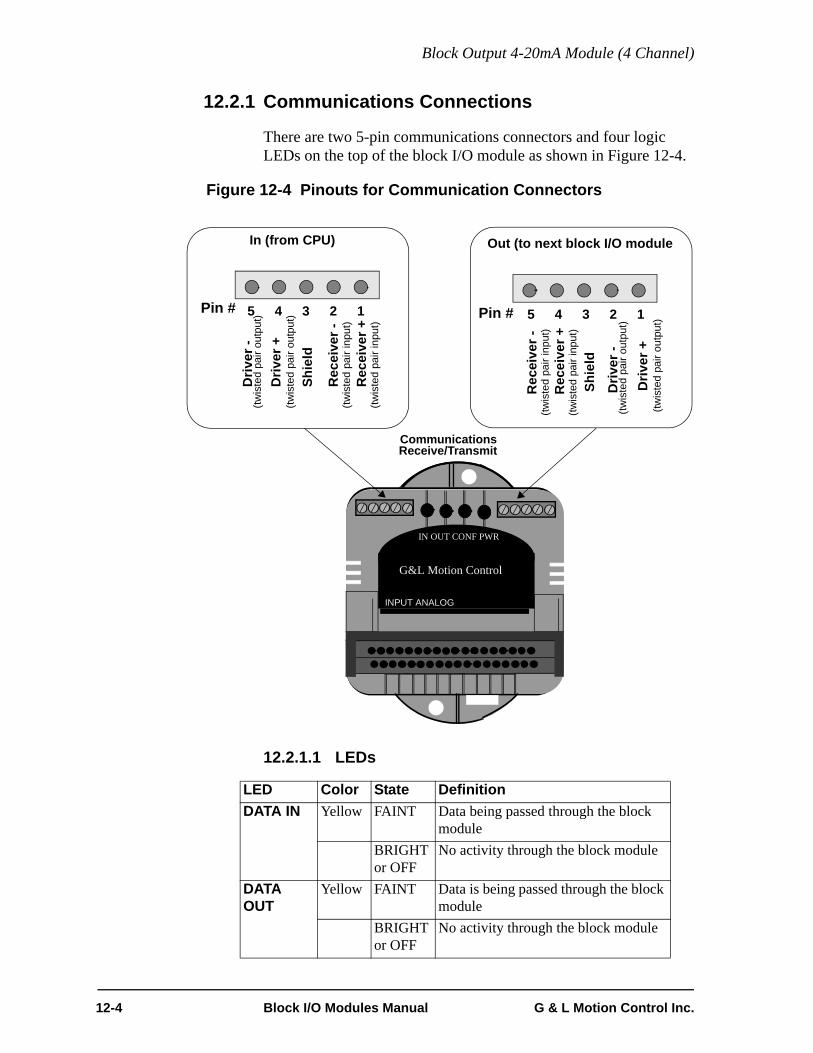
Block Output 4-20mA Module (4 Channel)
12.2.1 Communications Connections
There are two 5-pin communications connectors and four logic LEDs on the top of the block I/O module as shown in Figure 12-4.
Figure 12-4 Pinouts for Communication Connectors
12.2.1.1 LEDs
LED Color State DefinitionDATA IN Yellow FAINT Data being passed through the block
moduleBRIGHT or OFF
No activity through the block module
DATA OUT
Yellow FAINT Data is being passed through the block module
BRIGHT or OFF
No activity through the block module
CommunicationsReceive/Transmit
In (from CPU) Out (to next block I/O module
12345 12345Pin # Pin #
Rec
eive
r +(tw
iste
d pa
ir in
put)
Rec
eive
r -(tw
iste
d pa
ir in
put)
Shie
ld
Driv
er -
Driv
er +
(twis
ted
pair
outp
ut)
(twis
ted
pair
outp
ut)
Driv
er +
(twis
ted
pair
outp
ut)
Driv
er -
(twis
ted
pair
outp
ut)
Shie
ld
Rec
eive
r -(tw
iste
d pa
ir in
put)
Rec
eive
r +(tw
iste
d pa
ir in
put)
INPUT ANALOG
G&L Motion Control
IN OUT CONF PWR
12-4 Block I/O Modules Manual G & L Motion Control Inc.

Block Output 4-20mA Module (4 Channel)
CONFG Green ON Communication established with this block I/O module
OFF Communication not establishedPWR Green ON Internal +5V logic power supply OK
OFF No external 24V applied or internal 5V logic supply not OK
G & L Motion Control Inc. Block I/O Modules Manual 12-5

Block Output 4-20mA Module (4 Channel)
12.3 Theory of OperationThe CPU module sends the output module a 16-bit digital word for each channel used. Each digital word is converted to a corresponding current within the range 4-20mA. The current is brought out to a pair of screw terminal connections as a single-ended type current output.
You can adjust each channel in software for offset adjustments and gain scaling.
For safety reasons, all outputs are automatically reset to 4mA when a scan loss condition occurs.
All outputs have clamping diodes and a capacitor to permit the driving of non-resistive (i.e. inductive) loads.
All outputs can drive loads whose impedance is less than or equal to:
Example: If VEXT = 24V, then the maximum impedance equals:
The load range in this example is from 0 to 1075 Ω.
Anytime the load impedance is exceeded, the OPEN flag is set in software. Nor-mally, it is an open circuit that causes this flag to be set.
VEXT 2.5V–20mA
----------------------------- RLOAD=
24VEXT 2.5V–20mA
------------------------------------ 1075Ω=
12-6 Block I/O Modules Manual G & L Motion Control Inc.

Block Output 4-20mA Module (4 Channel)
12.4 Specification Table
Characteristic Block Output 4-20mA (4 ch) specification
Function Converts a 15-bit digital value into a 4-20mA analog current signal for each of four channels
Part number M.1017.3101
Field side connector 24 pin card edge connector, screw terminals
Output channels 4
Resolution 15 bits, or 32,768 steps over the full output range
Output characteristics @24V DC supply, with temperature = 25° (77°F)
Accuracy .25% FSR (Full Scale Range)
Output current, max. 20 mA
Output voltage after power up VOUT = 4mA * RLOAD
Response to “scan loss” All outputs reset to 4mA
Short circuit protection Current is limited to: IOUT = where IOUT = 4 to 20mA
Logic side LEDs, module status Data In LEDData Out LEDConfigured LEDPower LED
Module power requirements 200 mA from an external 24V DC supply (20 to 30V DC range)NOTE: 2.5A, 250 microsecond inrush at power on
G & L Motion Control Inc. Block I/O Modules Manual 12-7

Block Output 4-20mA Module (4 Channel)
CE Marked Conforms to Directives 73/23/EEC, 89/336/EEC, 92/31/EEC, 93/68/EEC by conforming to the following stan-dards:EN 50081-2:1993 EMC Generic Industrial EmissionsEN 50082-2:1995 EMC Generic Industrial ImmunityEN 61131-2:1994/A11:1996 Low voltage directive requirements for programmable controllersOperates with emissions below EN55011/ CISPR 11Class A limitsImmune to:• Electrostatic discharge (4K V contact mode, 8K V air discharge) per EN61000-4-2• RF electromagnetic fields per EN61000-4-3, ENV 50141, and ENV50204• Electrical fast transients per EN61000-4-4 • Magnetic fields per EN61000-4-8Refer to the EMC Guidelines for more information.
UL and C/UL Listed File No. E126417 NRAQ Programmable Controllers
Operating temperature range 7° C to 55° C (45° F to 131° F)
Storage temperature range -40° C to 85° C (-40° F to 185° F)
Humidity 5 to 95%, non-condensing
Physical size 4.05" wide x 4.825" high x 3" deep 102.9 mm x 122.6 mm x 76.2 mm
Vibration (per IEC 68-2-6) 10-57 Hz (constant amplitude .15 mm)57 - 2000 Hz (acceleration 2 g)
Shock (per IEC 68-2-27) Four shocks per axis (15g/11 msec)
12-8 Block I/O Modules Manual G & L Motion Control Inc.

Block Output 4-20mA Module (4 Channel)
THIS PAGE INTENTIONALLY BLANK
G & L Motion Control Inc. Block I/O Modules Manual 12-9

Block Output 4-20mA Module (4 Channel)
12-10 Block I/O Modules Manual G & L Motion Control Inc.

Block Output +10V DC Module (4 Channel)
13 Block Output +10V DC Module (4 Channel)
13.1 IntroductionThe output ±10V DC module has four independent D/A conversion channels. Each channel converts a 16-bit digital word into a differential type analog output signal. The full range of the output signal is - 10 V to + 10 V, with a resolution of 1 part in 65,536.
This module contains no potentiometers or hardware switches. All necessary adjustments are done in software.
Figure 13-1 Block Output ±10V DC Module (4 Ch)
CommunicationsReceive/Transmit
Connector
ScrewTerminal
OUTPUT ±10VDC
G&L Motion Control
IN OUT CONF PWR
Cover(shown open)
Communication/Status LEDs
G & L Motion Control Inc. Block I/O Modules Manual 13-1

Block Output +10V DC Module (4 Channel)
13.2 Connections Two screw terminal connections are assigned to each channel to carry the signals as shown in Figure 13-2.
In addition, the module has four screw terminal connections for terminating the shields. All four are connected internally, so they are the same point electrically.
Two connections are used to connect an external power supply.
Figure 13-2 Screw Terminal Connector Assignments
Each output channel is connected to a receiving device with twisted pair wires as shown in Figure 13-3. For extremely noisy environments, use shielded twisted pair wire.
The shield connections are internally connected to the Single Point Ground (SPG) to which the system rack is connected. No external connection should be made.
1 3 4 5 6 7 8 9 10 11 122
13 15 16 17 18 19 20 21 22 23 2414
+24V DC
ChassisCh4+
Ch2+
Ch3+
Ch1+ Ch1-
Ch3-
Shield
Shield
Ch2-
Ch4- DC ComShield
Shield
Ground
13-2 Block I/O Modules Manual G & L Motion Control Inc.
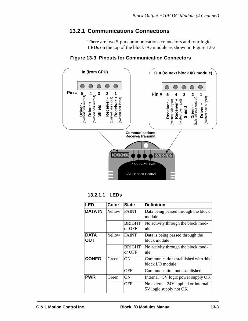
Block Output +10V DC Module (4 Channel)
13.2.1 Communications Connections
There are two 5-pin communications connectors and four logic LEDs on the top of the block I/O module as shown in Figure 13-3.
Figure 13-3 Pinouts for Communication Connectors
13.2.1.1 LEDs
LED Color State DefinitionDATA IN Yellow FAINT Data being passed through the block
moduleBRIGHT or OFF
No activity through the block mod-ule
DATA OUT
Yellow FAINT Data is being passed through the block module
BRIGHT or OFF
No activity through the block mod-ule
CONFG Green ON Communication established with this block I/O module
OFF Communication not establishedPWR Green ON Internal +5V logic power supply OK
OFF No external 24V applied or internal 5V logic supply not OK
CommunicationsReceive/Transmit
In (from CPU) Out (to next block I/O module)
12345 12345Pin # Pin #
Rec
eive
r +(tw
iste
d pa
ir in
put)
Rec
eive
r -(tw
iste
d pa
ir in
put)
Shie
ld
Driv
er -
Driv
er +
(twis
ted
pair
outp
ut)
(twis
ted
pair
outp
ut)
Driv
er +
(twis
ted
pair
outp
ut)
Driv
er -
(twis
ted
pair
outp
ut)
Shie
ld
Rec
eive
r -(tw
iste
d pa
ir in
put)
Rec
eive
r +(tw
iste
d pa
ir in
put)
CommunicationsReceive/Transmit
G&L Motion Control
IN OUT CONF PWR
G & L Motion Control Inc. Block I/O Modules Manual 13-3

Block Output +10V DC Module (4 Channel)
13.2.2 Analog Output Receiving Devices
It was assumed in Figure 13-2 that all the receiving device inputs were differential. However, you may connect the differential type output from this module to a single-ended input device. Figure 13-4 shows the difference between the two types of connections. Note that one wire in the twisted pair is connected to the 0 V terminal on the receiving device. This 0V terminal must be referenced to the SPG through the device's ground connection.
It is recommended that the receiving device have a differential input for best noise immunity.
Figure 13-4 Differential and Single-Ended Receiving Devices
1 3 4 5 6 7 8 9 10 11 122
13 15 16 17 18 19 20 21 22 23 2414
+24V DC
Ch1+ Ch1-
DC Com
To SPG
Ch1+ Ch1-
Ch2+ Ch2-
Ch2+ 0V
ShieldShield
Receiving Devices
+24V0V
Power Supply
Screw
Terminals
Differential Input Single-Ended Input
To SPG
GND
To SPG
GND
13-4 Block I/O Modules Manual G & L Motion Control Inc.
Block Output +10V DC Module (4 Channel)
13.3 Theory of OperationThe CPU module sends the output module a 16-bit digital word for each channel used. Each digital word is converted to a corresponding voltage within the range of ±10 V. The voltage is buffered and brought out to a pair of screw terminal connections as a differential type voltage output. This output is less subject to interference from electrical noise than a single-ended output would be.
You can adjust each channel in software for offset adjustments, gain scaling, and unipolar outputs.
For safety reasons, all outputs are automatically reset to 0 V when a scan loss condition occurs.
G & L Motion Control Inc. Block I/O Modules Manual 13-5

Block Output +10V DC Module (4 Channel)
13.4 Specification Table
Characteristic Output ±10V DC module specification
Function Converts a 16-bit digital word into a ±10 V analog signal for each of the four channels.
Part number M.1017.3140
Field side connector 24 pin card edge connector, screw terminals
Output channels 4
Resolution 16 bits, or 65536 steps over the full output range
Output voltage characteristics @24V DC supply, with temperature = 25°C(77°F)
Nominal voltage range ± 10 VDC
Voltage accuracy ±1% FSR (Full Scale Range)
Output current, max. @ ±10V ± 10 mA (1K Ω resistor)
Output voltage after power up 0 V ± 50 mV
Response to scan loss All outputs reset to 0 V ± 50 mV
Short circuit protection Current limited outputs
Logic side LEDs, module status Data In LEDData Out LEDConfigured LEDPower LED
Module power requirements 200 mA from an external 24V DC supply (20 to 30V DC range)NOTE: 2.5A, 250 microsecond inrush at power on
13-6 Block I/O Modules Manual G & L Motion Control Inc.

Block Output +10V DC Module (4 Channel)
CE Marked Conforms to Directives 73/23/EEC, 89/336/EEC, 92/31/EEC, 93/68/EEC by conforming to the following stan-dards:EN 50081-2:1993 EMC Generic Industrial EmissionsEN 50082-2:1995 EMC Generic Industrial ImmunityEN 61131-2:1994/A11:1996 Low voltage directive requirements for programmable controllersOperates with emissions below EN55011/ CISPR 11Class A limitsImmune to:• Electrostatic discharge (4K V contact mode, 8K V air discharge) per EN61000-4-2• RF electromagnetic fields per EN61000-4-3, ENV 50141, and ENV50204• Electrical fast transients per EN61000-4-4 • Magnetic fields per EN61000-4-8Refer to the EMC Guidelines for more information.
UL and C/UL Listed File No. E126417 NRAQ Programmable Controllers
Operating temperature range 7° C to 55° C (45° F to 131° F)
Storage temperature range -40° C to 85° C (-40° F to 185° F)
Humidity 5 to 95%, non-condensing
Physical size 4.05" wide x 4.825" high x 3" deep 102.9 mm x 122.6 mm x 76.2 mm
Vibration (per IEC 68-2-6) 10-57 Hz (constant amplitude .15 mm)57 - 2000 Hz (acceleration 2 g)
Shock (per IEC 68-2-27) Four shocks per axis (15g/11 msec)
G & L Motion Control Inc. Block I/O Modules Manual 13-7

Block Output +10V DC Module (4 Channel)
THIS PAGE INTENTIONALLY BLANK
13-8 Block I/O Modules Manual G & L Motion Control Inc.
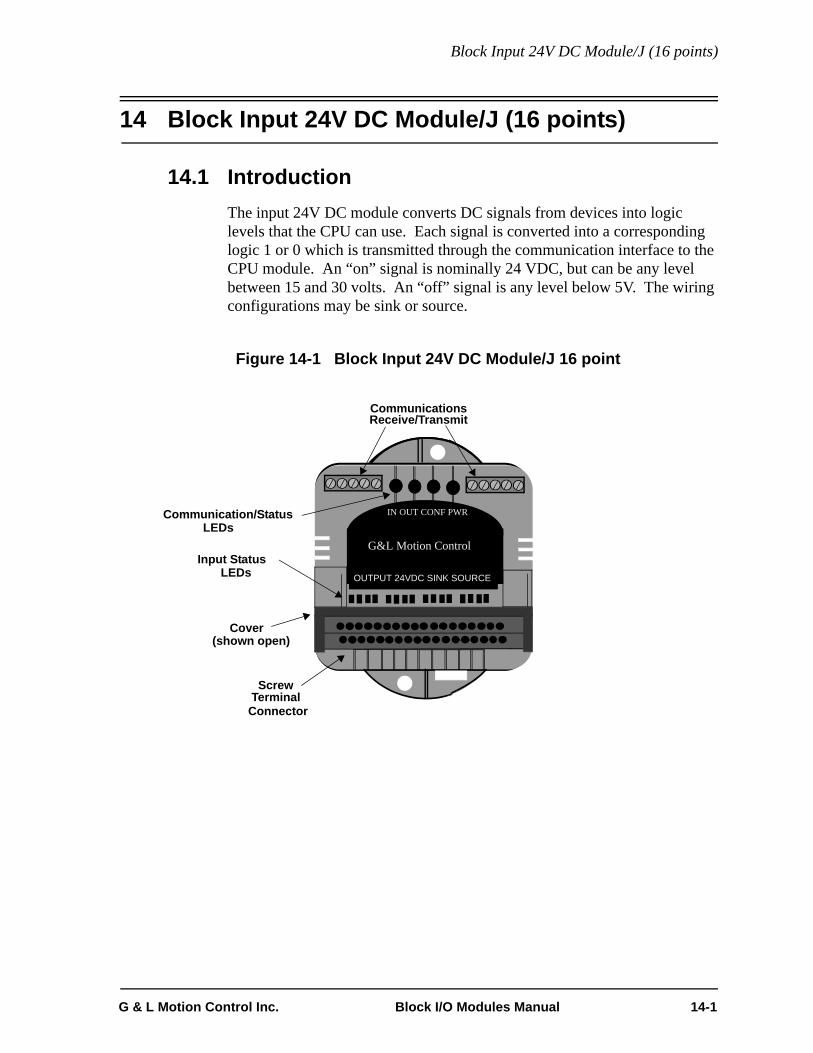
Block Input 24V DC Module/J (16 points)
14 Block Input 24V DC Module/J (16 points)
14.1 IntroductionThe input 24V DC module converts DC signals from devices into logic levels that the CPU can use. Each signal is converted into a corresponding logic 1 or 0 which is transmitted through the communication interface to the CPU module. An “on” signal is nominally 24 VDC, but can be any level between 15 and 30 volts. An “off” signal is any level below 5V. The wiring configurations may be sink or source.
Figure 14-1 Block Input 24V DC Module/J 16 point
CommunicationsReceive/Transmit
Connector
ScrewTerminal
OUTPUT 24VDC SINK SOURCE
G&L Motion Control
IN OUT CONF PWR
Cover(shown open)
Communication/Status LEDs
Input Status LEDs
G & L Motion Control Inc. Block I/O Modules Manual 14-1

Block Input 24V DC Module/J (16 points)
14.2 Connections A screw terminal connector is provided for each input and for each external power supply connection. The inputs are isolated in two groups of eight, with one additional terminal per group for the DC source/sink connection. The devices connected to terminals in the same group have a common DC supply and are wired in the same configuration, sink or source (Figure 14-2).
The external DC supply that powers the input signals should have a wire connected from its 0V (COMMON) terminal directly to the single-point ground used for the system rack.
Figure 14-2 Screw Terminal Connector Assignments
Typically, an external 24V DC supply is connected to pins 18 and 35.
In an earlier version of this module (M.1017.3092, 503-25907-01) 24V on pin 18 was internally connected to the pins now labeled as AUX 24V. This Block Input 24V DC Module/J requires an external jumper to provide this same functionality. 0V is still internally jumpered from pin 35 to pins labeled as 0V. These pins labeled as AUX24V and 0V make it convenient to connect 3-wire devices (e.g. a proximity switch) that require a voltage and ground connector. Also, AUX24V or 0V can be easily jumpered to a group’s sink/source connection.
NOTE
Using the supplied jumper, connect pin 17 to pin 18. This con-nection provides functionality identical to that of M.1017.3092(503-25907-01).
1 3 4 5 6 7 8 9 10 11 12 13 14 15 16 17 182
19 21 22 23 24 25 26 27 28 29 30 31 32 33 34 35 3620
Chassis
24V
0V
Group 2 SS
0V0V0V0V
24VIn1
In2
In3
In4
In5
In6
In7
In8
In9
In10
In11
In12
In13
In14
In15
In16
Group 1 SS
24V
0V0V
AUX 24VAUX
24VAUX
24VAUX
24VAUX
24VAUX
14-2 Block I/O Modules Manual G & L Motion Control Inc.

Block Input 24V DC Module/J (16 points)
The external jumpered connection using pin 17 and pin 18 provides the option of connecting an external fuse in series with the AUX24V intended for the external 3-wire devices. Essentially, connect pin 17 and pin 18 with a fuse instead of a jumper. If a short-circuit occurs in an external device, the block I/O communications will continue to function properly and only the devices connected to the fused 24V line will be shut down.
Figure 14-3 illustrates two groups of inputs using the same power supply. Each group can work independently of the other; one group may be sink and the other source. The DC power supply for each group may be different if required, but must be referenced to the same ground. Typically just one DC power supply is used, daisy-chained from one group to the next.
In Figure 14-3a, one group of eight inputs is shown with devices “sinking” current through the block DC Input module. The HOT terminal of the power supply is connected internally to the module by the jumper between 24V and Group 1 or 2 SS. The second group of eight inputs is shown with devices “sourcing” current through the block DC Input module. The COMMON terminal of the power supply is connected internally to the module by the jumper between 0V and Group 2 or 1 SS.
In Figure 14-3b, the first group is shown with devices “sourcing” current through the block DC Input module. The second group is shown with devices “sinking” current through the block DC Input module. In both examples the DC power supply is the same for Group 1 and 2. Use up to 14 AWG for field side wiring.
G & L Motion Control Inc. Block I/O Modules Manual 14-3

Block Input 24V DC Module/J (16 points)
Figure 14-3 Connectors for Two Groups of Inputs
1 2 3 4 5 6 7 8 9 10 11 12
IN 1
IN 2
13 14 15 16 17 18
19 20 21 22 23 24 25 26 27 28 29 30 31 32 33 34 35 36
IN 4
IN 3
IN 5
IN 6
IN 7
IN 8
Gro
up1
SS
AU
X 24
V IN 9
IN 1
0
IN 1
1
IN 1
2
Common
IN 1
3
IN 1
4
IN 1
5IN
16
Gro
up2
SS
0V
0V V+
DC PowerSupply
Hot
Group 2
Source
Group 1
Sink
1 2 3 4 5 6 7 8 9 10 11 12
IN 1
IN 2
13 14 15 16 17 18
19 20 21 22 23 24 25 26 27 28 29 30 31 32 33 34 35 36
IN 4
IN 3
IN 5
IN 6
IN 7
IN 8
Gro
up1
SS
0V
IN 9
IN 1
0
IN 1
1
IN 1
2
Hot
IN 1
3
IN 1
4
IN 1
5IN
16
Gro
up2
SS
AU
X 24
V
0V V+
DC PowerSupply
Common
Group 2
Sink
Group 1
Source
a. Group 1 Sink (Pins 8 and 9 Jumpered) and Group 2 Source (Pins 33 and 34 Jumpered)
b. Group 1 Source (Pins 25 and 26 Jumpered) and Group 2 Sink (Pins 16 and 17 Jumpered)
14-4 Block I/O Modules Manual G & L Motion Control Inc.

Block Input 24V DC Module/J (16 points)
14.2.1 Communications Connections
There are two 5-pin communications connectors and four logic LEDs on the top of the block I/O module as shown in Figure 14-4.
Figure 14-4 Pinouts for Communication Connectors
14.2.1.1 LEDs
LED Color State DefinitionDATA IN Yellow FAINT Data being passed through the block
moduleBRIGHT or OFF
No activity through the block module
DATA OUT
Yellow FAINT Data is being passed through the block module
BRIGHT or OFF
No activity through the block module
CONFG Green ON Communication established with this block I/O module
OFF Communication not establishedPWR Green ON Internal +5V logic power supply OK
OFF No external 24V applied or internal 5V logic supply not OK
CommunicationsReceive/Transmit
In (from CPU) Out (to next block I/O module)
12345 12345Pin # Pin #
Rec
eive
r +(tw
iste
d pa
ir in
put)
Rec
eive
r -(tw
iste
d pa
ir in
put)
Shie
ld
Driv
er -
Driv
er +
(twis
ted
pair
outp
ut)
(twis
ted
pair
outp
ut)
Driv
er +
(twis
ted
pair
outp
ut)
Driv
er -
(twis
ted
pair
outp
ut)
Shie
ld
Rec
eive
r -(tw
iste
d pa
ir in
put)
Rec
eive
r +(tw
iste
d pa
ir in
put)
G&L Motion Control
IN OUT CONF PWR
G & L Motion Control Inc. Block I/O Modules Manual 14-5

Block Input 24V DC Module/J (16 points)
14.3 Theory of OperationEach input is guaranteed “on” at 15 to 30 VDC and guaranteed “off” at 0 to 5 VDC; polarity doesn't matter. Its on/off state is converted to a corresponding logic 1 or 0. This logic state is transmitted through the communication interface to the CPU module, where the processor uses it as data in the ladder program. The logic side of the input is optically isolated from the field side.
An LED in the upper section of the module indicates the logic state of each input. Each group is represented by a horizontal row of LEDs. If you need to know whether voltage is present at the field side, use a voltmeter on the terminal screws. The shaded blocks in Figure 14-5 show the limits specified by the IEC. The lines show the maximum and minimum V/I of the inputs in this module. The voltage/current curve in this graph shows that the input module is well within the IEC Type 1 limits.
Figure 14-5 Input Characteristics Compared to IEC Standards
U in VoltsUHMAX 30
UNOM 2425
“ON” REGION
20
UHMIN 15(UTMAX)
10
5
0
-5
.5 2 4 6 8 10 12 14 15ITMIN IHMIN
INPUT CURRENT
I inmAMPS
TRANSITION REGION
“OFF” REGION
IMAX
(UTMIN )ULMAX
INPU
T VO
LTA
GE
MIN MAX
14-6 Block I/O Modules Manual G & L Motion Control Inc.

Block Input 24V DC Module/J (16 points)
IMPORTANT
Switching devices can sometimes have a leakage current that ex-ceeds the ITmin (current allowed when off) of an input module. In or-der to use such a device, an impedance (typically, a resistor) needs tobe used in parallel with the input.For example, some of the newer proximity switches use two wires in-stead of three. The third wire was used for a power or ground line.Without the third wire, the switch is easier to install. However, it re-quires more leakage current in the off state to power its internal cir-cuitry.As a conservative estimate, use the following formula to calculate anexternal resistance value. It keeps the input voltage at or below 2.4Vwhen the switching device is in the "off" state.
If the switch leakage specification is ≤ 1.7 mA, then:
Use a resistor less than or equal to 2.5 KΩ. Be sure that the wattageis adequate for the resistor when the switching device is in the “on”state remembering that:
2.4VSwitch Leakage 0.75mA–--------------------------------------------------------------- R≥
2.4V1.7 0.75mA–-------------------------------- 2.5KΩ≥
PVON
2
R----------=
G & L Motion Control Inc. Block I/O Modules Manual 14-7
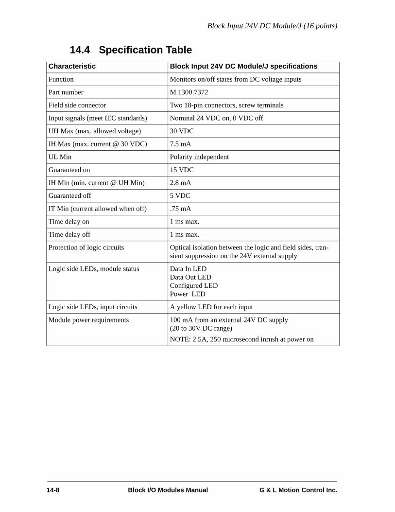
Block Input 24V DC Module/J (16 points)
14.4 Specification TableCharacteristic Block Input 24V DC Module/J specifications
Function Monitors on/off states from DC voltage inputs
Part number M.1300.7372
Field side connector Two 18-pin connectors, screw terminals
Input signals (meet IEC standards) Nominal 24 VDC on, 0 VDC off
UH Max (max. allowed voltage) 30 VDC
IH Max (max. current @ 30 VDC) 7.5 mA
UL Min Polarity independent
Guaranteed on 15 VDC
IH Min (min. current @ UH Min) 2.8 mA
Guaranteed off 5 VDC
IT Min (current allowed when off) .75 mA
Time delay on 1 ms max.
Time delay off 1 ms max.
Protection of logic circuits Optical isolation between the logic and field sides, tran-sient suppression on the 24V external supply
Logic side LEDs, module status Data In LEDData Out LEDConfigured LEDPower LED
Logic side LEDs, input circuits A yellow LED for each input
Module power requirements 100 mA from an external 24V DC supply (20 to 30V DC range)NOTE: 2.5A, 250 microsecond inrush at power on
14-8 Block I/O Modules Manual G & L Motion Control Inc.

Block Input 24V DC Module/J (16 points)
CE Marked Conforms to Directives 73/23/EEC, 89/336/EEC, 92/31/EEC, 93/68/EEC by conforming to the following stan-dards:EN 50081-2:1993 EMC Generic Industrial EmissionsEN 50082-2:1995 EMC Generic Industrial ImmunityEN 61131-2:1994/A11:1996 Low voltage directive requirements for programmable controllersOperates with emissions below EN55011/ CISPR 11Class A limitsImmune to:• Electrostatic discharge (4K V contact mode, 8K V air discharge) per EN61000-4-2• RF electromagnetic fields per EN61000-4-3, ENV 50141, and ENV50204• Electrical fast transients per EN61000-4-4 • Magnetic fields per EN61000-4-8Refer to the EMC Guidelines for more information.
UL and C/UL Listed File No. E126417 NRAQ Programmable Controllers
Operating temperature range 7° C to 55° C (45° F to 131° F)
Storage temperature range -40° C to 85° C (-40° F to 185° F)
Humidity 5 to 95%, non-condensing
Physical size 4.05" wide x 4.825" high x 3" deep 102.9 mm x 122.6 mm x 76.2 mm
Vibration (per IEC 68-2-6) 10-57 Hz (constant amplitude .15 mm)57 - 2000 Hz (acceleration 2 g)
Shock (per IEC 68-2-27) Four shocks per axis (15g/11 msec)
G & L Motion Control Inc. Block I/O Modules Manual 14-9

Block Input 24V DC Module/J (16 points)
THIS PAGE INTENTIONALLY BLANK
14-10 Block I/O Modules Manual G & L Motion Control Inc.

Block 24V DC 8 In/8 Out Module/J
15 Block 24V DC 8 In/8 Out Module/J
15.1 IntroductionThe Block 24V DC 8/8 module provides eight output points and eight input points.
The eight point output section sources voltage for individual loads from a DC power supply. The external supply is nominally 24 volts, but can be between 20 and 30 volts. Eight LEDs near the field terminal connector of the module indicate the logic state that drives each output. Another LED labeled SC turns on if any output attempts to drive a short circuit.
The eight point input section converts DC signals from devices into logic levels that the CPU can use. Each signal is converted into a corresponding logic 1 or 0 which is transmitted through the communication interface to the CPU module. An “on” signal is nominally 24 VDC, but can be any level between 15 and 30 volts. An “off” signal is any level below 5V. The wiring configurations may be sink or source. Eight LEDs near the field terminal connector of the module indicate the logic state of each input.
Figure 15-1 Block 24V DC 8In/8 Out Module/J
CommunicationsReceive/Transmit
Connector
ScrewTerminal
OUTPUT 24V DC
G&L Motion Control
IN OUT CONF PWR
Cover(shown open)
Short Circuit LED
Field SideInput LEDs
Communication/Status LEDs
Output Status LEDs
G & L Motion Control Inc. Block I/O Modules Manual 15-1

Block 24V DC 8 In/8 Out Module/J
15.2 Connections A screw terminal connection is provided for each output, input, and external power supply connection. The group of eight outputs and the group of eight inputs are isolated. The output group has its own short circuit protection with a short circuit LED indicator. The input group has additional terminal connections for the DC sink/source configuration.
The external DC supply that powers the output and/or input signals should have a wire connected from its 0V (COMMON) terminal directly to the single point ground used for the system rack.
Figure 15-2 Screw Terminal Connection Assignments
Typically, an external 24V DC supply is connected to pins 18 and 35.
In an earlier version of this module (M.1017.3090, 503-25906-01) 24V on pin 18 was internally connected to the pins now labeled as AUX 24V. This Block 24V DC 8In/Out Module/J requires an external jumper to provide this same functionality. 0V is still internally jumpered from pin 35 to pins labeled as 0V. These pins labeled as AUX24V and 0V make it convenient to connect 3-wire devices (e.g. a proximity switch) that require a voltage and ground connector. Also, AUX24V or 0V can be easily jumpered to a group’s sink/source connection.
The external jumpered connection using pin 17 and pin 18 provides the option of connecting an external fuse in series with the AUX24V intended for the external 3-wire devices. Essentially, connect pin 17 and pin 18 with a fuse instead of a jumper. If a short-circuit occurs in an external device, the block I/O communications will continue to function properly and only the devices connected to the fused 24V line will be shut down.
NOTE
Using the supplied jumper, connect pin 17 to pin 18. This con-nection provides functionality identical to that of M.1017.3090(503-25906-01).
1 3 4 5 6 7 8 9 10 11 12 13 14 15 16 17 182
19 21 22 23 24 25 26 27 28 29 30 31 32 33 34 35 3620
DC
Lin
e 1
DC
Com
1
DC
Out
1
DC
Out
3
DC
Out
5
DC
Out
7
DC
IN4
DC
IN6
24V
DC
IN8
DC
Out
2
DC
Out
4
DC
Out
6
DC
Out
8
DC
IN2 D
C IN
5
DC
IN7
DC
IN S
S
0V Cha
ssis
Outputs0V 0V 0V
AU
X 24
V
DC
IN S
S
DC
IN3
DC
IN1
AU
X 24
V
AUX
24V
Inputs
15-2 Block I/O Modules Manual G & L Motion Control Inc.

Block 24V DC 8 In/8 Out Module/J
Connections for the outputs are illustrated in Figure 15-3.
The common side of each load must be connected to the 0V terminal of the supply. This 0V terminal is connected to the SPG used by the system rack.
Use up to 14 AWG for field side wiring.
Figure 15-3 Connections for the Outputs
1 2 3 4 5
19 20 21 22 23
V+ 0VDCPowerSupply
To SPG
Line 1Com1
Out1Out2
Out3Out4
Out5Out6
Out7 Out8
G & L Motion Control Inc. Block I/O Modules Manual 15-3

Block 24V DC 8 In/8 Out Module/J
Connections for the inputs are illustrated in Figure Figure 15-4.
The eight inputs on the left are shown with devices “sourcing” current through the block module. The COMMON terminal of the power supply is connected inter-nally to the module by the jumper between 0V and the DC IN SS.
The eight inputs in the example on the right are shown with devices “sinking” cur-rent through the block module. The HOT terminal of the power supply is con-nected internally to the module by the jumper between 24V and DC IN SS.
Use up to 14 AWG for field side wiring.
Figure 15-4 Connectors for Inputs
10 11 12 13 14 15 16 17 18
28 29 30 31 32 33 34 35 36
DC
IN 1
DC
IN S
S
0V
0V V+
DC PowerSupply
Hot
Source
DC
IN 2
DC
IN 3
DC
IN 4
DC
IN 5
DC
IN 6
DC
IN 7
DC
IN 8
10 11 12 13 14 15 16 17 18
28 29 30 31 32 33 34 35 36
DC
IN 1
0V V+
DC PowerSupply
Common
Sink
DC
IN 2
DC
IN 3
DC
IN 4
DC
IN 5
DC
IN 6
DC
IN 7
DC
IN 8
DC
IN
SS
AU
X 24
V
15-4 Block I/O Modules Manual G & L Motion Control Inc.

Block 24V DC 8 In/8 Out Module/J
15.2.1 Communications Connections
There are two 5-pin communications connectors and four logic LEDs on the top of the block I/O module as shown in Figure 15-5.
Figure 15-5 Pinouts for Communication Connectors
15.2.1.1 LEDs
LED Color State DefinitionDATA IN Yellow FAINT Data being passed through the block
moduleBRIGHT or OFF
No activity through the block module
DATA OUT
Yellow FAINT Data is being passed through the block module
BRIGHT or OFF
No activity through the block module
CONFG Green ON Communication established with this block I/O module
OFF Communication not establishedPWR Green ON Internal +5V logic power supply
OKOFF No external 24V applied or inter-
nal 5V logic supply not OK
CommunicationsReceive/Transmit
G&L Motion Control
IN OUT CONF PWR
In (from CPU) Out (to next block I/O module)
12345 12345Pin # Pin #
Rec
eive
r +(tw
iste
d pa
ir in
put)
Rec
eive
r -(tw
iste
d pa
ir in
put)
Shie
ld
Driv
er -
Driv
er +
(twis
ted
pair
outp
ut)
(twis
ted
pair
outp
ut)
Driv
er +
(twis
ted
pair
outp
ut)
Driv
er -
(twis
ted
pair
outp
ut)
Shie
ld
Rec
eive
r -(tw
iste
d pa
ir in
put)
Rec
eive
r +(tw
iste
d pa
ir in
put)
G & L Motion Control Inc. Block I/O Modules Manual 15-5
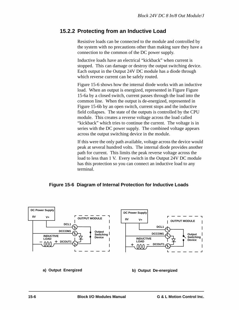
Block 24V DC 8 In/8 Out Module/J
15.2.2 Protecting from an Inductive Load
Resistive loads can be connected to the module and controlled by the system with no precautions other than making sure they have a connection to the common of the DC power supply.
Inductive loads have an electrical “kickback” when current is stopped. This can damage or destroy the output switching device. Each output in the Output 24V DC module has a diode through which reverse current can be safely routed.
Figure 15-6 shows how the internal diode works with an inductive load. When an output is energized, represented in Figure Figure 15-6a by a closed switch, current passes through the load into the common line. When the output is de-energized, represented in Figure 15-6b by an open switch, current stops and the inductive field collapses. The state of the outputs is controlled by the CPU module. This creates a reverse voltage across the load called “kickback” which tries to continue the current. The voltage is in series with the DC power supply. The combined voltage appears across the output switching device in the module.
If this were the only path available, voltage across the device would peak at several hundred volts. The internal diode provides another path for current. This limits the peak reverse voltage across the load to less than 1 V. Every switch in the Output 24V DC module has this protection so you can connect an inductive load to any terminal.
Figure 15-6 Diagram of Internal Protection for Inductive Loads
DC Power Supply
0V V+
DCL1
DCCOM1
INDUCTIVELOAD
DCOUT1
a) Output Energized
OUTPUT MODULE
OutputSwitchingDevice
DC Power Supply
0V V+
DCL1
DCCOM1
INDUCTIVELOAD
DCOUT1
b) Output De-energized
OUTPUT MODULE
OutputSwitchingDevice
15-6 Block I/O Modules Manual G & L Motion Control Inc.

Block 24V DC 8 In/8 Out Module/J
15.3 Theory of Operation
15.3.1 Outputs
Each output point is a solid state switch rated at .5 A. It turns on or off according to the logic state sent to it by the CPU. If the CPU sends it a logic 1, the switch closes and the device is powered. If the CPU sends a logic 0, the switch opens and power to the device is cut off. The CPU updates the logic state for each switch every time it scans the program.
The logic side of the switch is optically isolated from the field side. An LED gives the logic state of each switch. If you need to know whether voltage is actually present at the field side, use a voltmeter on the terminal screws.
The group of outputs has a .1 ohm series sensing resistor to protect against current overload in case the outputs are shorted to ground. When a short circuit condition is sensed, all outputs are pulsed on for approximately 130 microseconds every 100 milliseconds. Normal operation resumes after the short is removed. In addition, each output is protected with internal clamping diodes. Without clamping, high voltage transients (kickback) from inductive loads might damage the module.
15.3.2 Inputs
Each input is guaranteed “on” at 15 to 30 VDC and guaranteed “off” at 0 to 5 VDC; polarity doesn't matter. Its on/off state is converted to a corresponding logic 1 or 0. This logic state is transmitted through the communication interface to the CPU module, where the processor uses it as data in the ladder program. The logic side of the input is optically isolated from the field side.
An LED in the upper section of the module indicates the logic state of each input. The group of inputs is represented by a horizontal row of LEDs. If you need to know whether voltage is present at the field side, use a voltmeter on the terminal screws.
The shaded blocks in Figure 15-7 show the limits specified by the IEC. The lines show the maximum and minimum V/I of the inputs in this module. The voltage/current curve in this graph shows that the input module is well within the IEC Type 1 limits.
G & L Motion Control Inc. Block I/O Modules Manual 15-7
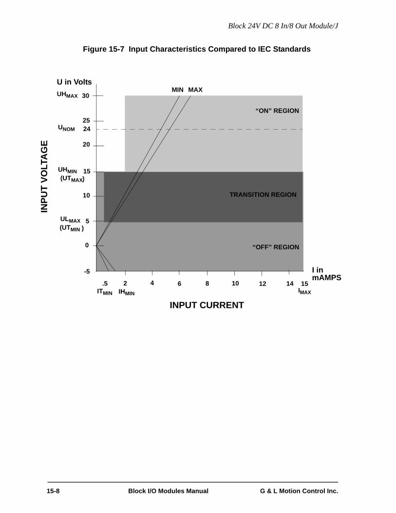
Block 24V DC 8 In/8 Out Module/J
Figure 15-7 Input Characteristics Compared to IEC Standards
U in VoltsUHMAX 30
UNOM 2425
“ON” REGION
20
UHMIN 15(UTMAX)
10
5
0
-5
.5 2 4 6 8 10 12 14 15ITMIN IHMIN
INPUT CURRENT
I inmAMPS
TRANSITION REGION
“OFF” REGION
IMAX
(UTMIN )ULMAX
INPU
T VO
LTA
GE
MIN MAX
15-8 Block I/O Modules Manual G & L Motion Control Inc.

Block 24V DC 8 In/8 Out Module/J
IMPORTANT
Switching devices can sometimes have a leakage current that ex-ceeds the ITmin (current allowed when off) of an input module. In or-der to use such a device, an impedance (typically, a resistor) needs tobe used in parallel with the input.For example, some of the newer proximity switches use two wires in-stead of three. The third wire was used for a power or ground line.Without the third wire, the switch is easier to install. However, it re-quires more leakage current in the off state to power its internal cir-cuitry.As a conservative estimate, use the following formula to calculate anexternal resistance value. It keeps the input voltage at or below 2.4Vwhen the switching device is in the "off" state.
If the switch leakage specification is ≤ 1.7 mA, then:
Use a resistor less than or equal to 2.5 KΩ. Be sure that the wattageis adequate for the resistor when the switching device is in the “on”state remembering that:
2.4VSwitch Leakage 0.75mA–--------------------------------------------------------------- R≥
2.4V1.7 0.75mA–-------------------------------- 2.5KΩ≥
PVON
2
R----------=
G & L Motion Control Inc. Block I/O Modules Manual 15-9

Block 24V DC 8 In/8 Out Module/J
15.4 Specification TableCharacteristic Block 24V DC 8 In/8 Out Module/J Specifications
Function Monitors on/off states from eight DC voltage inputs and sources an external DC supply to eight loads
Part number M. 1017.6042
Field side connector Two 18-pin connectors, screw terminals
Protection of logic circuits Optical isolation between the logic and field sides, tran-sient suppression for the 24V external supply
Logic side LEDs, module status Data In LEDData Out LEDConfigured LEDPower LED
Logic side LEDs, input status A yellow LED for each input
Logic side LEDs, output status A yellow LED for each output
Logic side LED, short circuit status A red LED lights to indicate a short circuit condition
Module power requirements 100 mA from an external 24V DC supply (20 to 30V DC range)NOTE: 2.5A, 250 microsecond inrush at power on
Input Section
Input signals Nominal 24 VDC on, 0 VDC off, conforming to IEC Type 1 inputs per IEC 1131-2
UH Max (max. allowed voltage) 30 VDC
IH Max (max. current @ 30 VDC) 7.5 mA
UL Min Polarity independent
Guaranteed on 15 VDC
IH Min (min. current @ UH Min) 2.8 mA
Guaranteed off 5 VDC
IT Min (current allowed when off) .75 mA
Time delay on 1 ms max.
Time delay off 1 ms max.
Output Section
DC source requirements Nominal 24V DC; range 20 to 30V DC
Output group One group of eight solid-state switches. The group uses an external DC supply. It must be referenced to SPG.
Short circuit protection for the group Pulses output for about 130 µsec every 100 msec until short is removed
15-10 Block I/O Modules Manual G & L Motion Control Inc.

Block 24V DC 8 In/8 Out Module/J
Maximum current per group 4 A of continuous current for the group; each switch is rated at .5 A continuous
Switch characteristics Solid-state switches
Time delay on for resistive loads 50 µsec max
Time delay off for resistive loads 50 µsec max
Leakage current in off state 0.5 mA max
Switch voltage, maximum ON 1 VDC max
Surge current, maximum 25 A for about 130 µsec every 100 msec
Response to scan loss All outputs are reset to the OFF state
CE Marked Conforms to Directives 73/23/EEC, 89/336/EEC, 92/31/EEC, 93/68/EEC by conforming to the following stan-dards:EN 50081-2:1993 EMC Generic Industrial EmissionsEN 50082-2:1995 EMC Generic Industrial ImmunityEN 61131-2:1994/A11:1996 Low voltage directive requirements for programmable controllersOperates with emissions below EN55011/ CISPR 11Class A limitsImmune to:• Electrostatic discharge (4K V contact mode, 8K V air discharge) per EN61000-4-2• RF electromagnetic fields per EN61000-4-3, ENV 50141, and ENV50204• Electrical fast transients per EN61000-4-4 • Magnetic fields per EN61000-4-8Refer to the EMC Guidelines for more information.
UL and C/UL Listed File No. E126417 NRAQ Programmable Controllers
Operating temperature range 7° C to 55° C (45° F to 131° F)
Storage temperature range -40° C to 85° C (-40° F to 185° F)
Humidity 5 to 95%, non-condensing
Physical size 4.05" wide x 4.825" high x 3" deep 102.9 mm x 122.6 mm x 76.2 mm
Vibration (per IEC 68-2-6) 10-57 Hz (constant amplitude .15 mm)57 - 2000 Hz (acceleration 2 g)
Shock (per IEC 68-2-27) Four shocks per axis (15g/11 msec)
G & L Motion Control Inc. Block I/O Modules Manual 15-11

Block 24V DC 8 In/8 Out Module/J
THIS PAGE INTENTIONALLY BLANK
15-12 Block I/O Modules Manual G & L Motion Control Inc.

Block Input/Output Analog Module (4 In 4 Out)
16 Block Input/Output Analog Module (4 In 4 Out)
16.1 IntroductionThe analog input section is designed to interface the PiC with voltage output devices to monitor such things as pressure, flow, speed, position, or temperature.
This section has four independent analog conversion channels. Each channel converts a unipolar or bipolar analog input voltage or current into a 14- bit digital value. This data is transmitted to the PiC’s CPU for processing.
An external current sense resistor can be added for each channel for use with 0 to 20 mA or 4 to 20 mA devices. This analog input section of the module contains no user adjustable potentiometers or hardware switches.
The analog output section has four independent D/A conversion channels. Each channel converts a 16-bit digital word into an analog output signal. The full range of the output signal is - 10 V to + 10 V, with a resolution of 1 part in 65,536. This section contains no potentiometers or hardware switches.
Figure 16-1 Block Input/Output Analog Module (4 In 4 Out))
CommunicationsReceive/Transmit
Connector
ScrewTerminal
INPUT/OUTPUT ANALOG
G&L Motion Control
IN OUT CONF PWR
Cover(shown open)
Communication/Status LEDs
G & L Motion Control Inc. Block I/O Modules Manual 16-1

Block Input/Output Analog Module (4 In 4 Out)
16.2 ConnectionsAll signals to/from the block input/output module must be connected to the screw terminal connectors through shielded twisted pair wires. See the discussion in the Hardware chapter on “Preventing electrical noise in data lines”.
There is one shield connection for each pair of inputs and one for each pair of outputs.
All shield connections are interconnected within the module so they are the same point electrically. These pins are internally connected to SPG. The shield at the device end of the cable is not connected.
Figure Figure 16-2 shows the assignments for all the screw terminal connections on the module.
Figure 16-2 Connections for the Input/Output Terminals
19 21 22 23 24 25 26 27 28 29 3020 32 33 34 35
1 3 4 5 6 7 8 9 10 11 122 14 15 16 17 1813
AnalogOutputChannel 2 +
AnalogOutputChannel 1 +
AnalogOutputChannel 3 +
AnalogInput
AnalogInputChannel 2 +
AnalogInputChannel 3 +
AnalogInputChannel 4 +
+ 24 DC
AnalogOutputChannel 1 -
Shield AnalogOutputChannel 2 -
Shield
31
AnalogOutputChannel 3 -
Shield Shield Shield Shield Shield Shield 0V
36
ChassisAnalogOutputChannel 4 -
AnalogInputChannel 1 -
AnalogInputChannel 2 -
AnalogInputChannel 3 -
AnalogInputChannel 4 -
AnalogOutputChannel 4 +
Channel 1+
NC NC NC NC NC NC NCNC NC
NC - no connection
16-2 Block I/O Modules Manual G & L Motion Control Inc.

Block Input/Output Analog Module (4 In 4 Out)
When connecting an analog voltage output device to the module, the positive wire of the twisted pair goes to the + screw terminal and the negative wire goes to the - screw terminal. Figure 16-3 illustrates these connections for channel two.
Figure 16-3 Voltage Input Connections
19 21 22 23 24 25 26 27 28 29 3020 32 33 34 35
1 3 4 5 6 7 8 9 10 11 122 14 15 16 17 1813
31 36
Ch 2+Ch 2-
Ch2RShield
+-
VoltageSignalSource
COM
To Single Point Ground (SPG)
G & L Motion Control Inc. Block I/O Modules Manual 16-3

Block Input/Output Analog Module (4 In 4 Out)
When using a 0 to 20 mA or 4 to 20 mA current output device, the positive wire of the twisted pair is connected to the + input and the negative wire is connected to the - input. In addition, an external 250 Ω resistor is connected to the same inputs as illustrated below.
Figure 16-4 Current Input Connections (0 to 20 or 4 to 20 mA)
19 21 22 23 24 25 26 27 28 29 3020 32 33 34 35
1 3 4 5 6 7 8 9 10 11 122 14 15 16 17 1813
31 36
NOTE: The accuracy of the current input can be no moreaccurate than the accuracy of the 250 Ω resistor used.
Ch 2+Ch 2-
+ -
To SPG
CurrentSignalSource
250 Ω
0 to 20 mA
4 to 20 mAor
+ -PowerSupply
Ch2RShield
16-4 Block I/O Modules Manual G & L Motion Control Inc.

Block Input/Output Analog Module (4 In 4 Out)
An alternative method of connecting a two wire 4 to 20 mA current device is shown in Figure 16-5.
Figure 16-5 Current Input Connections (4 to 20 mA)
19 21 22 23 24 25 26 27 28 29 3020 32 33 34 35
1 3 4 5 6 7 8 9 10 11 122 14 15 16 17 1813
31 36
Ch 2+
Ch 2-
250 Ω
Current Signal Source
4 to 20 mA
+-
PowerSupply
+Input frompower supply Output
To SPG
Ch2RShield
G & L Motion Control Inc. Block I/O Modules Manual 16-5
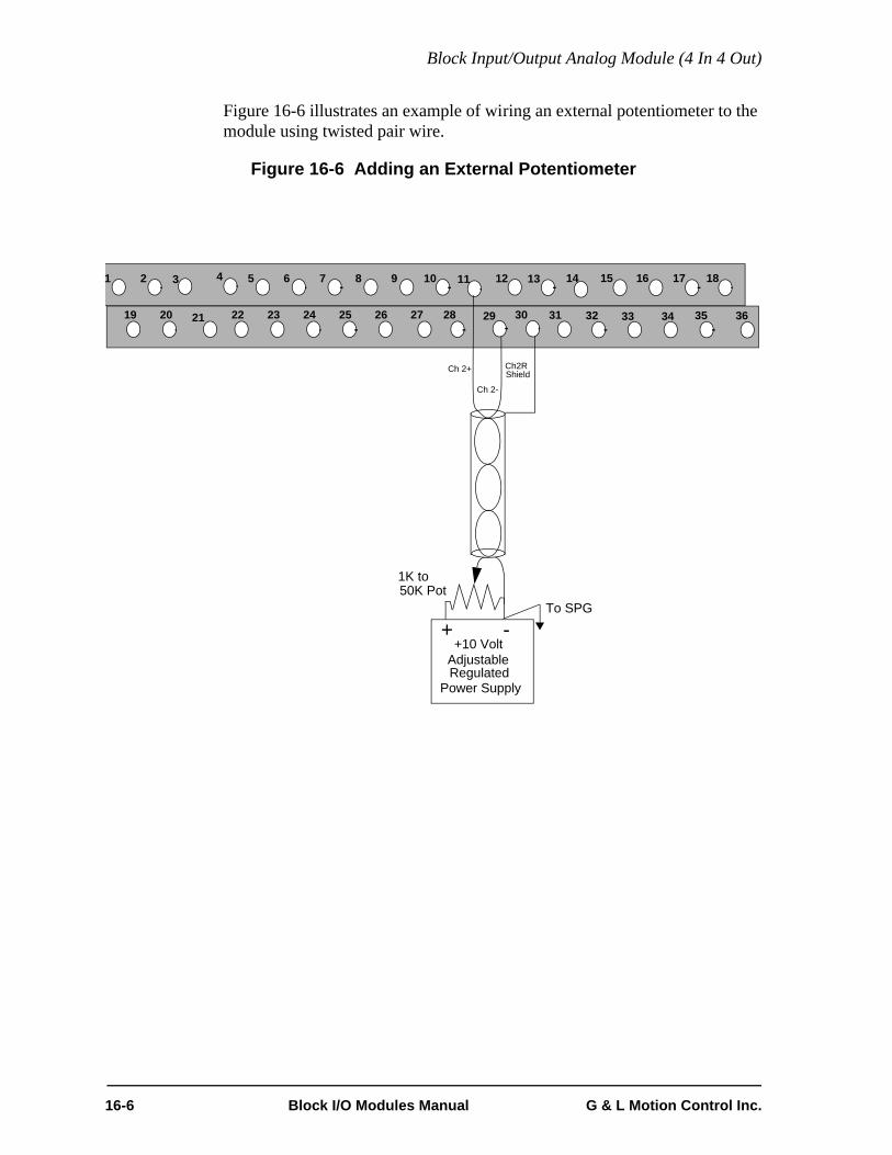
Block Input/Output Analog Module (4 In 4 Out)
Figure 16-6 illustrates an example of wiring an external potentiometer to the module using twisted pair wire.
Figure 16-6 Adding an External Potentiometer
19 21 22 23 24 25 26 27 28 29 3020 32 33 34 35
1 3 4 5 6 7 8 9 10 11 122 14 15 16 17 1813
31 36
+ -To SPG
+10 VoltAdjustableRegulated
Power Supply
Ch 2+
Ch 2-
1K to50K Pot
Ch2RShield
16-6 Block I/O Modules Manual G & L Motion Control Inc.

Block Input/Output Analog Module (4 In 4 Out)
16.2.1 Analog Output Receiving Devices
It was assumed in Figure 16-2 that all the receiving device inputs were differential. It is possible (but not recommended) to connect the single ended output from this module to a single-ended input device. Figure 16-7 shows the difference between the two types of connections. Note that one wire in the twisted pair is connected to the 0 V terminal on the receiving device. This 0V terminal must be referenced to the SPG through the device's ground connection.
It is recommended that the receiving device have a differential input for best noise immunity.
Figure 16-7 Differential and Single-Ended Receiving Devices
Ch2+ Ch2- Ch4+ 0V
Differential Input Single-Ended Input
To SPG
GND
To SPG
GND
19 21 22 23 24 25 26 27 28 29 3020 32 33 34 35
1 3 4 5 6 7 8 9 10 11 122 14 15 16 17 1813
31 36
Ch 2+
Ch 2-
Ch2RShield Ch 4+
Ch 4-
Ch4RShield
Receiving Devices
To SPG
+24V0V
Power Supply
G & L Motion Control Inc. Block I/O Modules Manual 16-7

Block Input/Output Analog Module (4 In 4 Out)
16.2.2 Communications Connections
There are two 5-pin communications connectors and four logic LEDs on the top of the block I/O module as shown in Figure 16-8.
Figure 16-8 Pinouts for Communication Connectors
16.2.2.1 LEDs
LED Color State DefinitionDATA IN Yellow FAINT Data being passed through the block
moduleBRIGHT or OFF
No activity through the block mod-ule
DATA OUT
Yellow FAINT Data is being passed through the block module
BRIGHT or OFF
No activity through the block mod-ule
CONFG Green ON Communication established with this block I/O module
OFF Communication not establishedPWR Green ON Internal +5V logic power supply OK
OFF No external 24V applied or internal 5V logic supply not OK
CommunicationsReceive/Transmit
In (from CPU) Out (to next block I/O module
12345 12345Pin # Pin #
Rec
eive
r +(tw
iste
d pa
ir in
put)
Rec
eive
r -(tw
iste
d pa
ir in
put)
Shie
ld
Driv
er -
Driv
er +
(twis
ted
pair
outp
ut)
(twis
ted
pair
outp
ut)
Driv
er +
(twis
ted
pair
outp
ut)
Driv
er -
(twis
ted
pair
outp
ut)
Shie
ld
Rec
eive
r -(tw
iste
d pa
ir in
put)
Rec
eive
r +(tw
iste
d pa
ir in
put)
G&L Motion Control
IN OUT CONF PWR
16-8 Block I/O Modules Manual G & L Motion Control Inc.
Block Input/Output Analog Module (4 In 4 Out)
16.3 Theory of OperationA 14- bit A/D converter samples each channel sequentially. These values are stored in memory on the module so that any channel value can be read by a PiC CPU while the A/D converter is processing another channel sample.
Each channel has a range of - 10V to + 10V. All inputs are differential and filtered.
The PiC CPU module sends the output module a 16-bit digital word for each channel used. Each digital word is converted to a corresponding voltage within the range of ±10 V. The voltage is buffered and brought out to a pair of screw terminal connections as a single ended voltage output. However, each output line has series inductance to improve noise immunity.
For safety reasons, all outputs are automatically reset to 0 V when a scan loss condition occurs.
G & L Motion Control Inc. Block I/O Modules Manual 16-9

Block Input/Output Analog Module (4 In 4 Out)
16.4 Specification Table
CharacteristicBlock Input/Output Analog Module (4 In 4 Out) Specification
Function Converts an analog input signal into a 14-bit digital word for each of four channels. Converts a 16-bit digital word into a ±10 V analog signal for each of four channels.
Part number M.1301.4145
Output channels 4
Input channels 4
Resolution 14 bits, or 16384 steps over the full input range,16 bits, or 65536 steps over the full output range.
Voltage Range Output ±10 V,Input ±10 V
Maximum Output Current (1KΩ load)
±10 mA
Power on output voltage 0V ±100 mV
Scan loss output voltage 0V ±100 mV
Accuracy Analog Output ±0.375% of FSR Drift ± 50ppm/°C,Analog Input ±.25 % of FSR
Sample Rate 800 µsec (200 µsec per channel)
Update rate 200 µsec (50 µsec per channel)
Common mode filter 3 dB @ 10 KHz
Differential mode filter 3 dB @ 475 Hz
Field side connector Two 18 pin card edge connectors, screw terminals
Logic side LEDs, module status Data In LEDData Out LEDConfigured LEDPower LED
Module power requirements 120 mA from an external 24V DC supply (20 to 30V DC range)
16-10 Block I/O Modules Manual G & L Motion Control Inc.

Block Input/Output Analog Module (4 In 4 Out)
CE Marked Conforms to Directives 73/23/EEC, 89/336/EEC, 92/31/EEC, 93/68/EEC by conforming to the following standards:EN 50081-2:1993EMC Generic Industrial EmissionsEN 50082-2:1995EMC Generic Industrial ImmunityEN 61131-2:1994/A11:1996 Low voltage directive requirements for programmable controllersOperates with emissions below EN55011/ CISPR 11 Class A limitsImmune to:•Electrostatic discharge (4K V contact mode, 8K V air discharge) per EN61000-4-2•RF electromagnetic fields per EN61000-4-3, ENV 50141, and ENV50204•Electrical fast transients per EN61000-4-4 •Magnetic fields per EN61000-4-8Refer to the EMC Guidelines for more information.
UL and C/UL Listed File No. E126417 NRAQ Programmable Controllers
Operating temperature range 7° C to 55° C (45° F to 131° F)
Storage temperature range -40° C to 85° C (-40° F to 185° F)
Humidity 5 to 95%, non-condensing
Physical size 4.05" wide x 4.825" high x 3" deep 102.9 mm x 122.6 mm x 76.2 mm
Vibration (per IEC 68-2-6) 10-57 Hz (constant amplitude .15 mm)57 - 2000 Hz (acceleration 2 g)
Shock (per IEC 68-2-27) Four shocks per axis (15g/11 msec)
G & L Motion Control Inc. Block I/O Modules Manual 16-11

Block Input/Output Analog Module (4 In 4 Out)
THIS PAGE INTENTIONALLY BLANK
16-12 Block I/O Modules Manual G & L Motion Control Inc.

Block Input J-K Thermocouple Module (8 channel)
17 Block Input J-K Thermocouple Module(8 channel)
17.1 IntroductionThe input J-K thermocouple module has independent thermocouple or analog con-version channels which receive signals from J or K type thermocouples or from a voltage source. Each channel converts an analog signal into a 14-bit digital word which is processed by the PiC CPU.
This module requires no hardware adjustments. All adjustments such as Fahren-heit or Celsius scaling and thermocouple ranges are software selectable.
Figure 17-1 Block Input J-K Thermocouple (8 Channel)
CommunicationsReceive/Transmit
Connector
ScrewTerminal
INPUT J-K THERMOCOUPLE
G&L Motion Control
IN OUT CONF PWR
Cover(shown open)
Communication/Status LEDs
G & L Motion Control Inc. Block I/O Modules Manual 17-1

Block Input J-K Thermocouple Module (8 channel)
17.2 Connections A screw terminal connector is provided for each input and for the external power supply connection.
The external DC supply that powers the module should have a wire connected from its 0V (COMMON) terminal directly to the single-point ground used for the system rack.
Thermocouple signal levels are very small (1°C is approximately 50 µV) and, consequently, sensitive to electrical noise. The module inputs are processed to reduce noise sensitivity.
To obtain the best noise immunity, route input cables away from sources of noise such as motors, AC wiring, etc. Use shielded cables, connecting the shields only at the module.
Figure 17-2 Screw Terminal Connector Assignments
1 3 4 5 6 7 8 9 10 11 12 13 14 15 16 17 182
19 21 22 23 24 25 26 27 28 29 30 31 32 33 34 35 3620
*TCI
Shield
* TCI = Thermocouple Input
1 +TCI1 -
TCI2 +
TCI2 -
TCI3 +
TCI3 -
TCI4 +
TCI4 -
TCI5 +
TCI5 -
TCI6 +
TCI6 -
TCI7 +
TCI7 -
TCI8 +
TCI8 -
+24VDC
Shield Shield Shield Shield Shield Shield Shield Shield Shield Shield Shield Shield Shield 0V ChassisShield Shield
17-2 Block I/O Moudles Manual G & L Motion Control Inc.

Block Input J-K Thermocouple Module (8 channel)
When connecting thermocouples to the module, the white wire of J type (the yellow wire of K type) is connected to the + input and the red wire of J or K type is connected to the - input as shown on the left in Figure 17-3. On the right is a shielded thermocouple connection.
Figure 17-3 Thermocouple Connections
When making an analog input connection to a ±100 mV type signal, shielded twisted pair wire should be used with the shield connected to the SHIELD connectors at the module as shown in Figure 17-4.
Figure 17-4 Analog Input Connections
1
2
Red (J or K)
White (J), Yellow (K)
Thermocouple connections to Channel 1
1
2
Thermocouple connections with shield
3
Ch 1 +
Ch 1 -
Ch 1 +
Ch 1 -19
20
(required to achieve CE immunity)
Red (J or K)
White (J), Yellow (K)
+
-SourceSignalVoltage
1
2
Ch 1 +
Ch 1 -
19
20
G & L Motion Control Inc. Block I/O Modules Manual 17-3

Block Input J-K Thermocouple Module (8 channel)
If the ±100 mV range will be exceeded, external resistors must be added. The resistors should be positioned as close to the Block I/O module as possible.
NOTE: Units are Vin in volts and R1 and R2 in K ohms.
Select a R1 value from .5K ohms to 2K ohms. Use the following formula to
calculate the value of R2:
For example, if the input range will be ±10 V and R1 = 1K ohm, then the value of
R2 would be:
A 100K ohm resistor could be used for R2 in this example. It is the closest stan-dard 1% value.
Figure 17-5 Analog Input Connections with External Resistors
R2 Vin 10×( )R1 260×R1 260+---------------------⎝ ⎠
⎛ ⎞=
R2 10V 10×( ) 1 260×1 260+------------------⎝ ⎠
⎛ ⎞=
R2 99.6K=
+
- SourceSignalVoltage
1
2 Ch 1 -19
20
R1Ch 1 +
R2
17-4 Block I/O Moudles Manual G & L Motion Control Inc.

Block Input J-K Thermocouple Module (8 channel)
17.2.1 Communications Connections
There are two 5-pin communications connectors and four logic LEDs on the top of the block I/O module as shown in Figure 17-6.
Figure 17-6 Pinouts for Communication Connectors
17.2.1.1 LEDs
LED Color State DefinitionDATA IN Yellow FAINT Data being passed through the block
moduleBRIGHT or OFF
No activity through the block module
DATA OUT
Yellow FAINT Data is being passed through the block module
BRIGHT or OFF
No activity through the block module
CONFG Green ON Communication established with this block I/O module
OFF Communication not establishedPWR Green ON Internal +5V logic power supply OK
OFF No external 24V applied or internal 5V logic supply not OK
CommunicationsReceive/Transmit
In (from CPU) Out (to next block I/O module)
12345 12345Pin # Pin #
Rec
eive
r +(tw
iste
d pa
ir in
put)
Rec
eive
r -(tw
iste
d pa
ir in
put)
Shie
ld
Driv
er -
Driv
er +
(twis
ted
pair
outp
ut)
(twis
ted
pair
outp
ut)
Driv
er +
(twis
ted
pair
outp
ut)
Driv
er -
(twis
ted
pair
outp
ut)
Shie
ld
Rec
eive
r -(tw
iste
d pa
ir in
put)
Rec
eive
r +(tw
iste
d pa
ir in
put)
G&L Motion Control
IN OUT CONF PWR
G & L Motion Control Inc. Block I/O Modules Manual 17-5

Block Input J-K Thermocouple Module (8 channel)
17.3 Theory of OperationThe input thermocouple module receives analog signals from thermocouples or analog inputs from other sources. It converts them to a 14 bit (13 bits plus sign bit) digital word for each channel in use. Each channel can be set up individually for three different thermocouple input ranges (see specification table) or for ±100 mV.
The module provides cold junction compensation. Cold junction compensation corrects for error voltages which occur at the point where the thermocouple wire terminates into the module connector. Always make the connection into the module with the thermocouple wire to ensure that cold junction compensation is effective.
All inputs are differential. They are filtered with a 5 ms time constant for noise immunity.
The ±100 mV input can be used only in applications which do not require a response time faster than 5 ms.
17.4 Thermocouple PrecautionsCertain precautions should be taken when working with thermocouples to ensure the integrity of your system.
• Avoid any vibration, bending or other mechanical stress which may strain the thermocouple wire and change its characteristics.
• Use 24 AWG solid or larger for runs less than 30 feet. Use 20 AWG or larger for runs greater than 30 feet. (The maximum ther-mocouple wire length is 1,000 feet.) Due to an approximate 1 microamp of bias current for open thermocouple detection, resis-tance of the thermocouple wire will introduce a fixed temperature error (i.e. 1 micro amp x 45 ohms = 45 micro volts, which corre-sponds to approximately 1 degree Celsius)
• Use shielded wire to protect from severe electrical noise.
• Use the thermocouple wire well within its temperature rating.
• Allow 20 minutes of warm up to reach rated accuracy.
17-6 Block I/O Moudles Manual G & L Motion Control Inc.

Block Input J-K Thermocouple Module (8 channel)
17.5 Specification Table
Characteristic Thermocouple module specification
Function Measure J or K type thermocouple wire inputsor ± 100 mV analog inputs
Part numbers M.1301.9807 (Beta)
Input channels 8
Resolution 14 bits (13 bits and sign bit)
Input voltage sensitivity (software selectable)
±100 mV max
J type thermocouple temperature ranges (at 25°C)
-150°C to 1200°C (-238°F to 2192° F)-35°C to 620°C (-31°F to 1148° F)-10°C to 280°C (+14°F to 536° F)
K type thermocouple temperature ranges (at 25°C)
-200°C to 300°C (328°F to 2372° F)-80°C to 20°C (-112°F to1508° F)-35°C to 415°C (-31°F to 779° F)
J or K type accuracy J type .26% of the 1350°C span K type .23% of the 1500°C span
±100 mV accuracy ± .1% full scale
Time between samples 47 msec
Noise rejection -150 dB @ 60 Hz common mode-7 dB @ 60 Hz differential mode
Cold junction compensation over full temperature range of module
Open thermocouple detection Indicated by software
Module power requirements 60 mA from an external 24VDC power supply(20 to 30 VDC range)
G & L Motion Control Inc. Block I/O Modules Manual 17-7

Block Input J-K Thermocouple Module (8 channel)
CE MarkedPending
Conforms to Directives 73/23/EEC, 89/336/EEC, 92/31/EEC, 93/68/EEC by conforming to the following standards:EN 50081-2:1993EMC Generic Industrial EmissionsEN 50082-2:1995EMC Generic Industrial ImmunityEN 61131-2:1994/A11:1996 Low voltage directive requirements for programmable controllersOperates with emissions below EN55011/ CISPR 11Class A limitsImmune to:•Electrostatic discharge (4K V contact mode, 8K V air discharge) per EN61000-4-2•RF electromagnetic fields per EN61000-4-3, ENV 50141, and ENV50204•Electrical fast transients per EN61000-4-4 •Magnetic fields per EN61000-4-8Refer to the EMC Guidelines for more information.
UL and C/UL Listed(Pending)
File No. E126417 NRAQ Programmable Controllers
Operating temperature range 7° C to 55° C (45° F to 131° F)
Storage temperature range -40° C to 85° C (-40° F to 185° F)
Humidity 5 to 95%, non-condensing
Physical size 4.05" wide x 4.825" high x 3" deep 102.9 mm x 122.6 mm x 76.2 mm
Vibration (per IEC 68-2-6) 10-57 Hz (constant amplitude .15 mm)57 - 2000 Hz (acceleration 2 g)
Shock (per IEC 68-2-27) Four shocks per axis (15g/11 msec)
17-8 Block I/O Moudles Manual G & L Motion Control Inc.

5-Axis Integrated Stepper Module
18 5-Axis Integrated Stepper Module
Figure 18-1 5-Axis Integrated Stepper Module
CFG
24V
32V
1
6
8
1
1
1
1
1
1
6
6
6
5
6
8
8
8
8
1
1
1
1
16
Configure LED (Yellow)
24V DC LED (Green)
32V DC LED (Green)
Stepper 1 Encoder Connector
Stepper 1 Motor Connector
Stepper 2 Motor Connector
Stepper 3 Motor Connector
Stepper 4 Motor Connector
Stepper 5 Motor Connector
Stepper 2 Encoder Connector
Stepper 3 Encoder Connector
Stepper 4 Encoder Connector
Stepper 5 Encoder Connector
Power Terminal Block
1
6
POWER
ENCDR 1
MOTOR 1
ENCDR 2
MOTOR 3
ENCDR 3
MOTOR 3
ENCDR 4
MOTOR 4
MOTOR 5
ENCDR 5
OUTIN
Stepper Module to Next BIO
PE
FAISM
CPU/Preceding BIO to
Module IN LED (Yellow)
Stepper Module to Next BIO
Stepper Module Connector
CPU/Preceding BIO toStepper Module IN LED (Yellow)
Module Connector
CPU/Preceding BIO toStepper Module OUT LED (Yellow)
Stepper Module to Next BIOModule OUT LED (Yellow)
NXT BLK
OUTIN
CPU
G & L Motion Control Inc. Block I/O Modules Manual 18-1

5-Axis Integrated Stepper Module
18.1 Introduction This block I/O module provides the following:
• 5 output stepper motor channels
• 5 input encoder channels
• 5 24V DC inputs
The 5-Axis Integrated Stepper Module (FAISM) contains 5 channels. Each channel can control one stepper motor and receive data from one encoder. The FAISM actually consists of three Block I/O modules contained in one enclosure. Two of the Block I/O modules contain two stepper/encoder channels. The third module contains one stepper/encoder channel.
18.1.1 Output Stepper
• Each stepper channel can control one stepper motor up to 4A peak current. The maximum step rate is one million steps per sec-ond.
• Commands and control data are sent to the module, and status and position information are received from the module, via software.
• Status bits include Profile Enabled, Profile Paused, At Velocity, Que Empty, Que Full, Control Word Not Processed, Firmware Version.
18.1.2 Input Encoder
• Each encoder channel can interface to one SSI encoder. Informa-tion from each encoder can be read by the application program.
• Some SSI encoders have a “double read” capability that allows the FASIM to inform the application program if the encoder posi-tion is valid.
• Status bits include Drive Overcurrent Fault, SSI Double Read Invalid, 24V Status Input (may be used for Encoder Battery Low).
18-2 Block I/O Modules Manual G & L Motion Control Inc.

5-Axis Integrated Stepper Module
18.1.3 Dimensions
Figure 18-2 Dimensions and Mounting
Front View (2 FAISMs shown) Side View
2.0"8.940"
13.060"
12.685"
.250"
1.570"
13.50"
.190"
.750"
.375"
NOTE: The 2" center-to-center spacing between modules providesthe required 1/2" spacing between module cabinets.
G & L Motion Control Inc. Block I/O Modules Manual 18-3

5-Axis Integrated Stepper Module
18.1.4 LEDs
LED Color State DefinitionCPU/Preceding BIO to Stepper Module IN
Yellow BRIGHT
DIMDARK
Open wire, or wires reversed, or hardware defectNormal communicationCPU not scanning (idle)
CPU/Preceding BIO to Stepper Module OUT
BRIGHTDIMDARK
Hardware defectNormal communicationCPU not scanning (idle)
Stepper Moduleto Next BIO Module IN
BRIGHT
DIMDARK
Open wire, or wires reversed, or hardware defectNormal communicationCPU not scanning (idle)
Stepper Moduleto Next BIO Module OUT
BRIGHTDIMDARK
Hardware defectNormal communicationCPU not scanning (idle)
CFG Green ON Communication established with this stepper module
OFF Communication not established
24V Green ON Internal +5V logic power sup-ply OK
OFF No external 24V applied or internal 5V logic supply not OK
32V Green ON Stepper output power supply OK
OFF No external 32V applied
18-4 Block I/O Modules Manual G & L Motion Control Inc.

5-Axis Integrated Stepper Module
18.2 ConnectionsCage-clamp 2.5 mm connectors are used for the CPU, Motor and Encoder connections. Screw terminal connectors are used for the Power connections.
18.2.1 Pin Assignments
Table 18-1: BIO CPU In ConnectorPin Number Signal Description
1 Fromcpu+ + signal in from controller or previousBlock I/O module
2 Fromcpu- - signal in from controller or previousBlock I/O module
3 Shield Internal shield
4 Tocpu+ + signal out to controller or nextBlock I/O module
5 Tocpu- - signal out to controller or nextBlock I/O module
6 NC N/A
Table 18-2: BIO CPU Out ConnectorPin Number Signal Description
1 Tobio+ + signal out to another Block I/O Module
2 Tobio- - signal out to another Block I/O Module
3 Shield Internal shield
4 Frombio+ + signal in from another Block I/O Module
5 Frombio- - signal in from another Block I/O Module
6 NC N/A
Table 18-3: Stepper Encoder ConnectorsPin Number Signal Description
1 SSIdata+ + data in from SSI encoder
2 SSIdata- - data in from SSI encoder
3 SSIclk+ + clock out to SSI encoder
4 SSIclk- - clock out to SSI encoder
5 24V Status Input Monitor 24V DC source signal
6 +24V + 24V source to SSI encoder
7 +24Vcom +24V DC common to SSI encoder
8 Shield Internal shield
G & L Motion Control Inc. Block I/O Modules Manual 18-5

5-Axis Integrated Stepper Module
18.2.2 FAISM to Stepper Motor Connections
FAISM to stepper motor connections are illustrated in Figure 18-3.
Figure 18-3 FAISM to Stepper Motor Connections
Table 18-4: Stepper Motor Connectors
Pin Number Signal Description
1 Phase A+ Current Phase A + to motor
2 Phase A- Current Phase A - to motor
3 Phase B+ Current Phase B + to motor
4 Phase B- Current Phase B - to motor
5 Shield Internal shield
6 Chassis Gnd Chassis Ground to motor
Table 18-5: Power Connector
Pin Number Signal Description
1 +24V + 24V source to FAISM
2 +24Vcom +24V DC common to FAISM
3 Chassis Gnd Chassis Ground to FAISM
4 32V AC 32V Source to FAISM
5 32V AC Com 32V AC Common to FAISM
B+B-
A-A+
B-B+A-
A+
Motor
Shielded CableFAISM
43
2156
18-6 Block I/O Modules Manual G & L Motion Control Inc.

5-Axis Integrated Stepper Module
18.2.3 FAISM Encoder Connections
All signals to the encoder connections must be through shielded twisted pair wires. These wires must be protected against electrical noise because of the speed and/or voltage levels of the signals transmitted through them.
Figure 18-4 FASIM Encoder Connections
18.2.4 FAISM DC Input Connections
The “24V status” input is intended for use as the Encoder “Battery Low” status input if the encoder is so equipped, however, it can be used as a general purpose DC input if desired. This input is non-isolated. If a nominal 24V DC is applied to this input, the associated status bit will be “on”. If a nominal 0V is applied to this input the associated status bit will be “off”.
SSI Encoder FAISM
6
7
+24V DC
0V
+ DATA
- DATA
+5V
+24V
+ CLOCK
- CLOCK
+5V
6
7
1
2
1
2
3
4
3
4
+24V
24V Status5 5
120Ω
8
G & L Motion Control Inc. Block I/O Modules Manual 18-7

5-Axis Integrated Stepper Module
Figure 18-5 Input Power Connections
Note: The 32V AC generated to the FAISM must be isolated and the 24V DC “0V” line must be connected to single point ground. Failure to observe these precautions could result in damage to the FAISM and/or connected devices.
18.3 Theory of Operation
18.3.1 FAISM Theory of Operation
The stepper section of the FAISM module is part of an open loop control system used to control a stepper motor. The diagram in Figure 18-6 illustrates one axis being controlled by the FAISM. Digital signals from the FAISM module are converted into fixed increments of motion via the FAISM stepper drive. This allows the stepper motor to move the load accurately and reliably by following the number of input steps.
Figure 18-6 Open Loop Stepper System
AC 32VAC
+24V
+ 12345
+24VDC0VChassis Ground32VAC32VAC
FAISM
Single Point Ground
Controller
CPU DataTransfer
FAISMStepperDrive
LOAD
StepperMotor
18-8 Block I/O Modules Manual G & L Motion Control Inc.
5-Axis Integrated Stepper Module
The FAISM controls the position, velocity, and acceleration of the stepper motor. The number of pulses generated by the FAISM provides distance information (steps) and the rate of these pulses provides velocity information (steps/sec). The rate of change of the pulse rate provides acceleration/deceleration information (steps/sec/sec).
Commands (acc/dec rates, maximum velocity, reference position, distance, position, and velocity moves) and control data (E-stop, C-stop, start, pause, continue, modes) are sent to the module and status and position information are received from the module via software. Each channel can have up to 500 commands queued up on the module.
The step rate programmed by you for a velocity command (or calculated by the FAISM during acceleration or deceleration) versus the actual rate output from the FAISM is defined by the following equation:
where X is the integer quotient of
The FAISM also contains control bits that set the number of microsteps per full motor steps. These bits are controlled by the application software using the STEP_CMD function. Assuming a standard 1.8 degree stepper motor is being used, the steps/revolution can be programmed to various values ranging from 400 to 51,200. The actual motor speed will then depend on the step rate as previously described, and the programmed steps/rev value.
Another factor affecting motor performance is the peak phase current. The peak phase current is programmable using the STEP_CMD function. Although it is beyond the scope of this document, it is the user’s responsibility to set the peak phase current to the application’s requirements within the motor’s capabilities.
One last point to consider is the energy used by the stepper motor when the motor is not rotating. The peak “at rest” current is also set by the application using the STEP_CMD function. The “at rest” current should be set high enough to prevent unwanted motion, but as low as possible to prevent unnecessary heat generation which shortens motor life.
ActualRate 10 106×X
--------------------=
10 106×ProgrammedRate-----------------------------------------------
G & L Motion Control Inc. Block I/O Modules Manual 18-9

5-Axis Integrated Stepper Module
18.3.2 FAISM Encoder Theory of Operation
The FAISM is designed to interface to 24 bit absolute multi-turn encoders that contain an SSI interface. Furthermore, if encoder power is to be obtained from the FAISM’s encoder connector, the encoder must accept 24V DC (nominal) as its power source.
The encoder/FAISM SSI interface is an industry standard and will not be discussed in detail in this document. However, the pertinent details of the FAISM’s implementation of the SSI interface will be presented.
The FAISM generates a 250kHz clock that is sent to the encoder. 51 clock pulses are generated; the clock line remains idle for50µs and the process is repeated. The following describes the data expected by the FAISM on each rising edge of the clock:
When the application software reads the encoder position from the FAISM, it always reads bits 2 through 25. Bits 28-51 are used internally by the FAISM, and are not available to the application software. When using SSI encoders that have the “Double Read” feature, bits 2-25 should always equal bits 28-51. If they are not equal, there has been an error in the transmission of data from the encoder to the FAISM. Every time the application software reads the encoder position from the FAISM, the FAISM compares bits 2-25 to bits 28-51, and if they are equal, sets the “Double Read Valid” flag which can be read by the application. If the SSI encoder connected supports the Double Read function, then this flag has meaning, and if this flag is ever false when not read, the last encoder position read should be ignored. If the SSI encoder connected does not support the Double Read function, the “Double Read Valid” flag should be ignored.
18.3.3 DC Input Theory of Operation
Each input is guaranteed “on” at 15 to 30 VDC and guaranteed “off” at 0 to 5 VDC. Its on/off state is converted to a corresponding logic 1 or 0. This logic state is transmitted through the communication interface to the CPU module, where the processor uses it as data in the ladder program. The logic side of the input is not optically isolated from the field side.
1 Not used, can be 0 or 1
2-25 24 bits of position, bit 2 is the most significant bit
26-27 Not used, can be 0 or 1
28-51 24 bits of position, bit 28 is the most significant bit
18-10 Block I/O Modules Manual G & L Motion Control Inc.

5-Axis Integrated Stepper Module
18.4 Specification Table
Characteristic Specifications - 5-Axis Integrated Stepper Module
General
Function Three modules where two modules control two stepper motors each and the third module controls one stepper motor. Five channels of stepper motor control. Five encoder inputs. Five DC inputs
Part number M.1302.7612
CPU Connectors Cage-clamp 2.5 mm 6-pin connector block, pluggable,28-20 AWG/5A
Encoder Connectors Cage-clamp 2.5 mm 8-pin connector block, pluggable,28-20 AWG/5A
Motor Connectors Cage-clamp 2.5 mm 6-pin connector block, pluggable,28-20 AWG/5A
Power Terminal Block Screw terminal connectors, pluggable,24-12 AWG/15A
Drive current per phase (running)
.4-4A peak, software programmable,
Drive current per phase (stopped)
0-4A peak, software programmable
Steps/rev(1.8° motor)
400 through 51,200, software programmable
DC Input Off = < 5V, ON = > 15V, max = 30V
Motor Power 16-33V AC, isolated
Logic Power 20-30V DC, 300 mA
Cable length, maximum, motor cable
100 ft.
LEDs, logic and module status
Refer to Section 18.1.4 LEDs.
Operating temperature range
5° C to 55° C (41° F to 131° F),Rear center of back plate max. temp. 85° C (185 ° F)
Storage temperature range -40° C to 85° C (-40° F to 185° F)
Humidity 5 to 95%, non-condensing
G & L Motion Control Inc. Block I/O Modules Manual 18-11

5-Axis Integrated Stepper Module
CE Marked Conforms to Directives 73/23/EEC, 89/336/EEC, 92/31/EEC, 93/68/EEC by conforming to the following standards:EN 50081-2:1993 EMC Generic Industrial EmissionsEN 50082-2:1995 EMC Generic Industrial ImmunityEN 61131-2:2003 Programmable controllers - equipment requirements
and testsRefer to the EMC Guidelines for more information.
UL and C/UL Listed File No. E126417 NRAQ Programmable Controllers
Physical size 1.5" wide 13.5" high 9.0" deep 38.1 mm 342.9 mm 228.6 mm
Vibration 5-9 Hz (constant amplitude .35 mm)9-150 Hz (acceleration 1 g)
Shock 3 shocks each direction per axis (15g/11msec)
Stepper Section
Position range ±2,147,352,575 steps
Step rate 0 to 1,000,000 steps/sec
Step rate accuracy
where X is the integer quotient of
Acceleration/deceleration rate
1 to 16,777,215 steps/sec/sec
Reference range ±2,147,352,575 steps
Response to scan loss Pulse output halted, motor current = 0
Encoder Section
Type Absolute Multi-turn
Number of Position Bits 24
Clock Rate 250 kHz
Cable length, max. 500 ft. maximum
ActualRate 10 106×X
--------------------=
10 106×ProgrammedRate-----------------------------------------------
18-12 Block I/O Modules Manual G & L Motion Control Inc.

INDEXSymbols±10V DC
block output 13-1±10V DC block output
connections 13-2specifications 13-6theory of operation 13-5
Numerics5-Axis Integrated Stepper Module (FAISM)
connectionsDC input power 18-8to encoder 18-7to stepper motor 18-6
dimensions and mounting 18-3illustrated 18-1input encoder 18-2introduction 18-2LEDs 18-4output stepper 18-2pin assignments 18-5specifications 18-10, 18-11theory of operation
DC input 18-10encoder 18-10general 18-8
Aanalog output receiving devices 13-4
Bblock ±10V DC output
LEDs 13-3block 24V DC 8/8 5-1
LEDs 5-1, 15-1specifications 5-10, 15-10
block 24V DC 8/8/J 15-1block 4-20mA output 12-1block analog input 11-1
connections 11-2, 11-4, 11-7, 16-2, 16-4,16-8
analog output device 11-3, 16-3LEDs 11-7, 16-8specifications 11-9, 16-10
theory of operation 11-8, 16-9block I/O
connections 3-4, 4-4, 5-5, 6-4, 7-6, 8-4,14-5, 15-5, 17-5
guidelines 2-1LEDs 3-4, 4-4, 5-5, 6-4, 7-6, 8-4, 14-5,
15-5, 17-5safety 2-2troubleshooting guide 2-6wiring guidelines 2-3
block input 24V DC 4-1connections 4-2, 14-2, 17-2specifications 4-7, 14-8, 17-7theory of operation 4-5, 5-7, 14-6, 15-7,
17-6block input 24V DC/J 14-1block input connections 10-15block input J-K Thermocouple 17-1block input/output analog 16-1block output ±10V DC
connections 13-3block output 24V DC source 3-1
connections 3-2LEDs 3-1, 6-1specifications 3-7theory of operation 3-6
block output 4-20mALEDs 12-4specifications 12-7
block output 4-20mA inputconnections 12-2
block output 4-20mA Moduletheory of operation 12-6
block output stepper/input encoder/input24VDC
theory of operation 10-17block output4-20mA
connections 12-4block resolver 9-7
connections 9-6LEDs 9-6
block stepper 10-2connections 10-3, 10-16LEDs 10-16specifications 10-22theory of operation 10-17
G & L Motion Control Inc. Block I/O Modules Manual IND-1

Cclamping diode 12-6common source
connections 10-7drive inputs 10-7
common terminal 7-2communications
connections±10V DC block output 13-3block analog input 11-7, 16-8block I/O 3-4, 4-4, 5-5, 6-4, 7-6, 8-4,
14-5, 15-5, 17-5block output 4-20mA 12-4block resolver 9-6block stepper 10-16
connections±10V DC block output 13-2block analog input 11-2, 16-2block input 10-15block input 24V DC 4-2, 14-2, 17-2block output 24V DC source 3-2block output 4-20mA 12-2block stepper 10-3input 120V AC 8-2output 120/240V AC 6-2relay output 7-2
counterup/down 10-19
currentleakage 4-6, 5-9, 8-6, 10-21, 14-7, 15-9sinking 4-2, 5-4, 14-3, 15-4sourcing 4-2, 5-4, 14-3, 15-4
current output device 11-4, 16-4current-limiting resistor 10-5
DD/A conversion channels
±10V DC block output 13-1, 16-1differential drivers 10-14
connections 10-10inputs 10-10
diodeclamping 12-6input 10-5
distribution of block I/O modules 2-5drivers
differential 10-10, 10-14encoder 10-14recommended 10-14single-ended 10-8, 10-14
Eelectrical service & maintenance safety 1-6encoder
drivers 10-14incremental 10-18quadrature 10-18, 10-19
Ffeedback 9-3frequency 10-19
Ggrounding
protective earth 1-2guidelines
block I/O 2-1
IIEC 4-5, 5-7, 8-5, 10-20, 14-6, 15-7incremental
encoder 10-18inductive load 12-6
internal diode 3-5, 5-6, 15-6protection from 3-5, 5-6, 15-6
input 120V AC 8-1connections 8-2LEDs 8-5specifications 8-7theory of operation 8-5
input sensitivityblock analog input 11-8
inspectionsafety 1-4
internal diodeand inductive loads 3-5, 5-6, 15-6
JJ-K thermocouple
analog input connections 17-3
Kkickback 3-5, 5-6, 15-6
IND-2 Block I/O Modules Manual G & L Motion Control Inc.

Llatch
counter value 10-19LEDs
block ±10V DC output 13-3block 24V DC 8/8 5-1, 15-1block analog input 11-7, 16-8block I/O 3-4, 4-4, 5-5, 6-4, 7-6, 8-4, 14-
5, 15-5, 17-5block input 24V DC 4-5, 5-7, 14-6, 15-7block output 24V DC source 3-1, 6-1block output 4-20mA 12-4block resolver 9-6block stepper 10-16, 10-20input 120V AC 8-5relay output 7-1, 7-8
loss of feedbackdetection 9-7, 10-14
Mmanual cleaning procedure 1-7modules
block 24V DC 8/8 5-1block 24V DC 8/8/J 15-1block 4-20mA output 12-1block analog input 11-1block input 24V DC 4-1block input 24V DC/J 14-1block input J-K Thermocouple 17-1block input/output 16-1block output ±10V DC 13-1block output 24V DC source 3-1block stepper 10-2input 120V AC 8-1relay output 7-1resolver block input 9-1
Nnoise
filterblock analog input 11-8
normally closed 7-2, 7-7normally open 7-2, 7-7
Ooperation
safety 1-5opto-coupler
connections 10-6drive inputs 10-5
output 120/240V ACconnections 6-2specifications 6-6theory of operation 6-5
Ppeak reverse voltage 3-5, 5-6, 15-6procedure
manual cleaning 1-7protective earth
grounding 1-2pull-up resistor 10-9
Qquadrature
counting pulses 10-19encoder 10-18, 10-19phase output 9-7
Rreceiving devices
analog output 13-4differential 13-4single-ended 13-4
reference phase output 9-7relay output 7-1
connections 7-2LEDs 7-1, 7-8specifications 7-9
relaysform A type 7-1, 7-2form C type 7-1
common terminal 7-2normally closed 7-2normally open 7-2
resistive load 3-5, 5-6, 15-6resistor
current sensing 11-1, 16-1current-limiting 10-5pull-up 10-9
resolver block input 9-1specifications 9-8
G & L Motion Control Inc. Block I/O Modules Manual IND-3

theory of operation 9-7rotor coil 9-7
Ssafety
cleaning 1-7electrical service & maintenance 1-6inspection 1-4operation 1-5signs 1-2system 1-1
safety concernsblock I/O 2-2
signalpairs 9-2, 10-12sine wave 9-1, 9-7square wave 10-18thermocouple 17-2
signssafety 1-2
sine wave signal 9-1, 9-7single-ended drivers 10-8, 10-14specifications
±10V DC block output 13-6block 24V DC 8/8 5-10, 15-10block analog input 11-9, 16-10block input 24V DC 4-7, 14-8, 17-7block output 4-20mA 12-7block output 24V DC source 3-7block stepper 10-22input 120V AC 8-7
output 120/240V AC 6-6relay output 7-9resolver block input 9-8
square wave signal 10-18stator coil 9-7
Ttroubleshooting
block I/O 2-6
Uup/down counter 10-19
Vvoltage
peak reverse 3-5, 5-6, 15-6
Wwarning labels 1-3wiring
±10V DC block output 13-2block analog input 11-2, 16-2block input 24V DC 4-2, 14-2, 17-2block output 24V DC source 3-2block output 4-20mA 12-2input 120V AC 8-2output 120/240V AC 6-2relay output 7-2
wiring guidelinesblock I/O 2-3
IND-4 Block I/O Modules Manual G & L Motion Control Inc.