Embed Size (px)
Citation preview
NSCM: D2356
Blind Encoder
BE6400-01-(XX)
(for Becker Mode S transponders)
INSTALLATION AND OPERATION
Ma nu al DV 69804.03 / AN 0594.547-071
Be cker Flug funk werk GmbH • Ba den-Airpark B 108 • 77836 Rhein müns ter • Ger ma ny
Te le pho ne +49 (0) 7229 / 305-0 • Fax +49 (0) 7229 / 305-217
http://www.be cker-avionics.de · e-mail: info@be cker-avionics.de or sup port@be cker-avionics.de
Init ial Issue:August 2006 34-50-11 May 2007

© Copyright by Be cker Flug funk werk GmbH 77836 Rheinmünster / Germany
All rights reserved. Subject to technical changes.
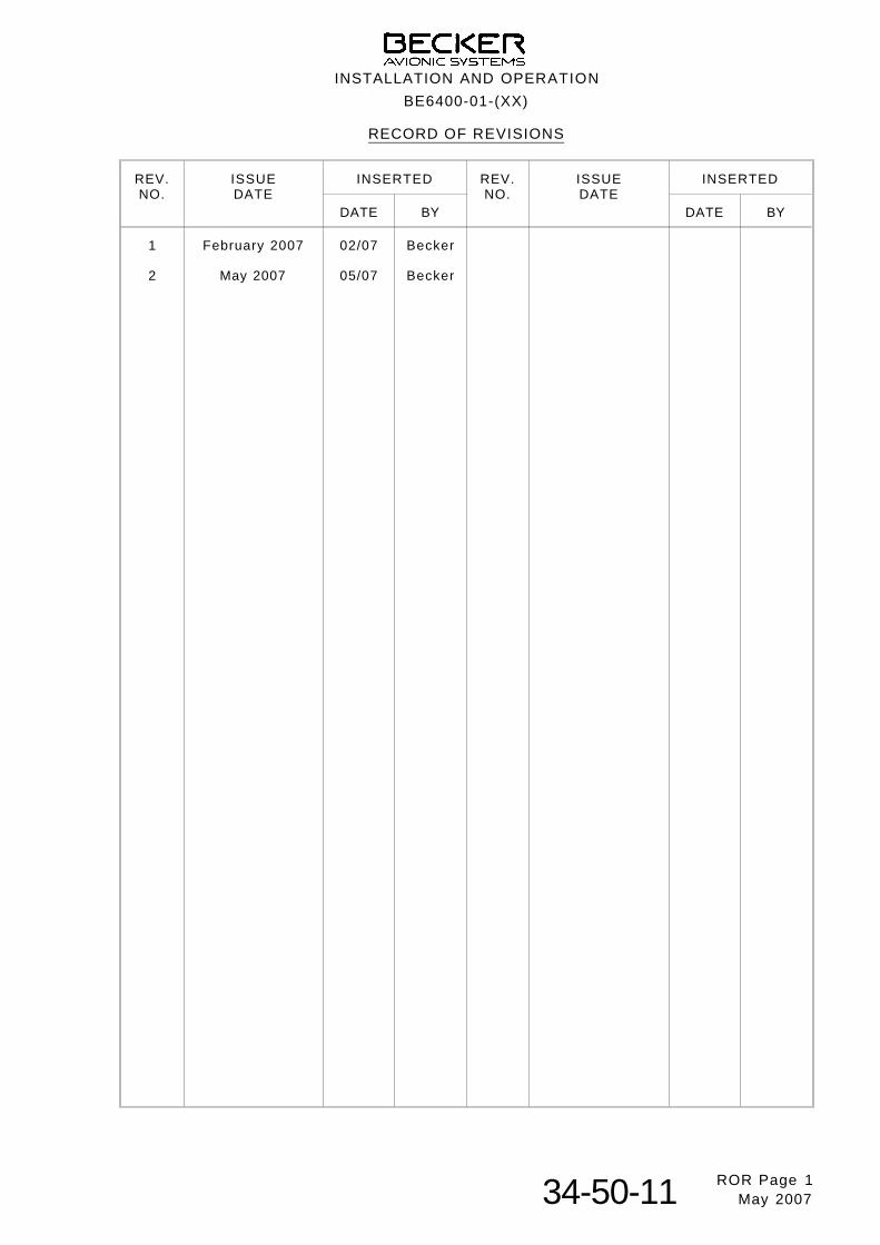
RE CORD OF RE VI SIONS
REV.NO.
IS SUEDATE
IN SER TED REV.NO.
IS SUEDATE
IN SER TED
DATE BY DATE BY
1
2
February 2007
May 2007
02/07
05/07
Becker
Becker
INSTALLATION AND OPE RA TI ON
BE6400-01-(XX)
ROR Page 134-50-11 May 2007
BLANK
INSTALLATION AND OPE RA TI ON
BE6400-01-(XX)
ROR Page 2 34-50-11 August 2006
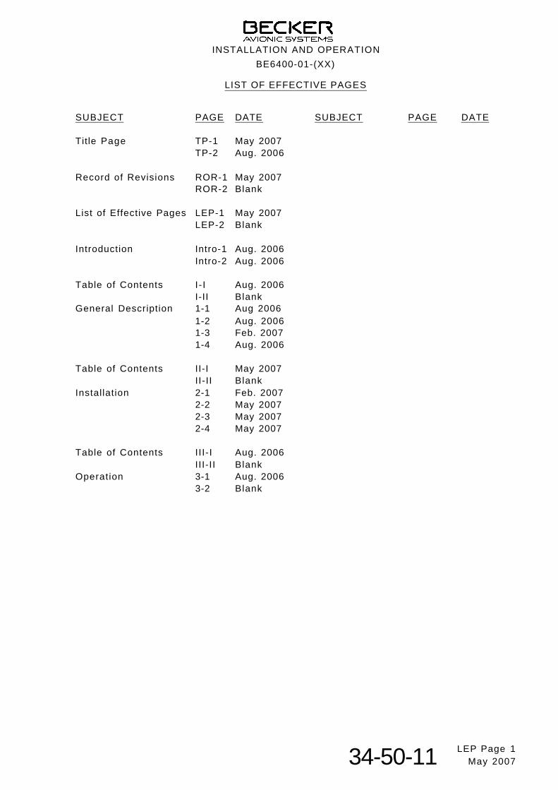
LIST OF EF FEC TI VE PA GES
SUB JECT PAGE DATE SUB JECT PAGE DATE
Tit le Page TP-1 May 2007TP-2 Aug. 2006
Record of Revisions ROR-1 May 2007ROR-2 Blank
List of Effective Pages LEP-1 May 2007LEP-2 Blank
Introduction Intro-1 Aug. 2006Intro-2 Aug. 2006
Table of Contents I- I Aug. 2006I-II Blank
General Description 1-1 Aug 20061-2 Aug. 20061-3 Feb. 20071-4 Aug. 2006
Table of Contents II-I May 2007II-II Blank
Installation 2-1 Feb. 20072-2 May 20072-3 May 20072-4 May 2007
Table of Contents III-I Aug. 2006III-II Blank
Operation 3-1 Aug. 20063-2 Blank
IN STAL LA TI ON AND OPE RA TI ON
BE6400-01-(XX)
LEP Page 134-50-11 May 2007

BLANK
IN STAL LA TI ON AND OPE RA TI ON
BE6400-01-(XX)
LEP Page 234-50-11 August 2006
IN TRO DUC TI ON
1. Gen eral
The Blind Encoder BE6400-01-(XX) for Becker Mode S transponders Class 2, Level 2es in accordance with ETSO-C88a and Class 2B in accordance with TSO-C88a isdes cri bed in this ma nu al “Installation and Operation”.
2. Manufacturer
The Blind Encoder was de ve lo ped and is ma nu fac tur ed by :
Be cker Flug funk werk GmbHBa den-Airpark B 10877836 Rhein müns ter / Germany
Te le pho ne: +49 (0) 7229 / 305-0Te le fax: +49 (0) 7229 / 305-217http://www.be cker-avionics.dee-mail: info@be cker-avionics.de or sup port@be cker-avionics.de
CER TI FIED QUA LI TY SYS TEM
The Be cker qua l i ty ma na ge ment sys tem is cer ti f ied ac cor ding to :
DIN EN ISO 9001:2000 CERT Reg. - Nr. 12 100 20985
LI CEN SES AND AP PRO VALS
DE.21G.0075 Ap pro val as ma nu fac tu rer to EASA PART 21
DE.145.0166 Ap pro val as main ten an ce or gani za ti on toEASA PART 145
3. Sa fe ty information
n The installation of the Blind Encoder into an aircraft may be carried outonly by an authorized installation company.
4. Lay out of manual
The ma nu al is divi ded into three chapters:
- GE NE RAL DES CRIP TI ON
- IN STAL LA TI ON
- OPERATION
INSTALLATION AND OPE RA TI ON
BE6400-01-(XX)
IN TRO Page 134-50-11 August 2006
5. Re vi sions of the manual
All chan ges to the ma nu al are re cor ded con se cu ti ve ly on the pre-page “Record ofRevi sions”.
6. List of ab bre via t ions
ADLP Avionics Data Link ProcessorALT Altitude or transponder ALT modeALTS-/+ Data interface for serial encoding alt imeterAN Article NumberATC Air Traffic ControlBFW Becker Flugfunkwerk GmbHDV Manual identif ication numberEASA European Avia ti on Sa fe ty Agen cyEIA Electronic Industry AssociationETSO European Technical Standard OrderEUROCAE European Organization for Civil Aviation EquipmentFAA Federal Avia ti on Ad mi nis tra t i onFL Flight Levelft feetGND GroundID Identif ierNSCM Nato Supply Code of ManufacturersRF Radio FrequencyRTCA Radio Technical Commission for AeronauticsSI Surveil lance Iden t i f ierSUPP Equipment supply voltage DCTSO Technical Standards OrderXPDR Transponder
INSTALLATION AND OPE RA TI ON
BE6400-01-(XX)
IN TRO Page 234-50-11 August 2006
TAB LE OF CON TENTS
GE NE RAL DES CRIP TI ON Page
1. Ap pli ca ti on 1-1
2. Ge ne ral des crip ti on 1-1
3. Tech ni cal data 1-2
4. Soft wa re 1-3
5. Approvals 1-3
6. Equipment 1-4
7. Ac ces so ries 1-4
Fig. 1-1 Blind Encoder BE6400-01-(XX) 1-1
INSTALLATION AND OPE RA TI ON
BE6400-01-(XX)
Page I -I34-50-11 August 2006
BLANK
INSTALLATION AND OPE RA TI ON
BE6400-01-(XX)
Page I-II34-50-11 August 2006
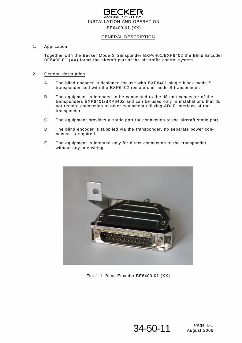
GENERAL DESCRIPTION
1. Ap pli ca ti on
Together with the Becker Mode S transponder BXP6401/BXP6402 the Blind Encoder BE6400-01-(XX) forms the aircraft part of the air traffic control system.
2. Ge ne ral des crip ti on
A. The blind encoder is designed for use with BXP6401 single block mode Stransponder and with the BXP6402 remote unit mode S transponder.
B. The equipment is intended to be connected to the J8 unit con nec tor of thetransponders BXP6401/BXP6402 and can be used only in installations that donot require connection of other equipment util izing ADLP interface of thetransponder.
C. The equipment provides a static port for connection to the aircraft static port.
D. The blind encoder is supplied via the transponder, no separate power con-nection is required.
E. The equipment is intented only for direct connection to the transponder,without any interwiring.
Fig. 1-1 Blind Encoder BE6400-01-(XX)
INSTALLATION AND OPERATION
BE6400-01-(XX)
Page 1-134-50-11 August 2006
3. Technical data
A. General data
Power supply supplied through pin 4 of XPDR(BXP640X unit connector J8)
Equipment input voltage 3.2 to 6.0 V DC
Current consumption max. 12 mA
Start-time of reporting altitude ≤ 1.5 seconds
Measurement range -1000...20000 ft
Altitude increments 100 ft
Pressure data interface RS-422 serial, compatible to BXP640X and ALT mode UPS/AT
Data transfer:- Baud rate 1200- No of data bits 8- No of stop bits 1- Parity None
Operating altitude up to 20000 ft
Operating temperature range - 15° C to + 55° C
Storage temperature range - 40° C to + 85° C
Environmental conditions in accordance with EUROCAE/RTCA ED-14D/DO-160D(see section C.)
Insulation resistance betweencase and electrical circuits > 5 MΩ
Mechanical dimensions 62.9 x 63 x 14.8 mm (L x W x H)(2.476 x 2.480 x 0.583 inch)
Weight approx. 100 g (0.225 lb)
B. Altitude data output
The equipment is provide an output for transmission of altitide and statusreports. The output is differential and provide voltage levels compatible withEIA-422 standard:
Logic state Non-inverting output Inverting output
0 max. 0.5 V min. 2.2 V
1 min. 2.2 V max. 0.5 V
INSTALLATION AND OPERATION
BE6400-01-(XX)
Page 1-234-50-11 August 2006
C. Environmental qualification
EUROCAE/RTCA ED-14D/DO-160D
Condition Section Cat. Description
Temperature and Altitude 4.0 A4Low Ground Survival Temperature 4.5.1 A4 -40 deg CLow Operating Temperature 4.5.1 A4 -15 deg CHigh Ground Survival Temp. 4.5.2 A4 +85 deg CHigh Ope ra ting Temp. 4.5.2 A4 +55 deg CIn-flight Loss of Coo ling 4.5.4 Z No for ced coo ling re qui red – No test
re qui redAl t i tu de 4.6.1 A4 20,000 ftDe com pres si on 4.6.2 A4 20,000 ftOver pres su re 4.6.3 A4 -15,000 ftTem pe ra tu re Va ria ti on 5.0 B 5 deg C/minHu mi di ty 6.0 A Standard humidity environmentShock and Crash Sa fe ty 7.0 B Fixed-wing aircrafts and helicoptersVi brat ion 8.0 S
UCat. S, vi brat ions test cur ve MCat. U, vi brat ions test cur ve G
Ex plo si on Pro of ness 9.0 X No test requiredWa ter pro of ness 10.0 X No test requiredFluids Sus cep ti bi li ty 11.0 X No test requiredSand and Dust 12.0 X No test requiredFun gus Re sis tan ce 13.0 X No test requiredSalt Spray 14.0 X No test requiredMag ne tic Ef fect 15.0 Z 1 deg deflection at 0.3 mPo wer In put 16.0 BVol ta ge Spi ke 17.0 AAu dio Freq. Con duc ted Sus cep ti bi -l i ty
18.0 X
In du ced Sig nal Sus cep ti bi l i ty 19.0 A Interference-free operation desirableRa dio Fre quen cy Sus cep ti bi li ty 20.0 WW Interim High Intensity Ratiated FieldsSpu ri ous RF Emis si on 21.0 B Equipment where interference should
be controlled to a tolerable levelLight ning In du ced Tran sients Sus -cep ti bi li ty
22.0 A3E3
Pin test waveform A, level 3Cable bundle test waveform E, level 3
Light ning Di rect Ef fects 23.0 X No test requiredIcing 24.0 X No test requiredElec tro sta tic Disch ar ge 25.0 A Equipment operated in an aerospace
environment
Note: With exception of the overpressure test (Section 4.6.3 of EUROCAE/RTCA ED-14D/ DO-160D) all qualification tests were applied to the combination BECKER BXP6401 and BECKER BE6400.
4. Soft wa re
The Blind Encoder BE6400-01-(XX) is con trol led by a microcontroller. The soft wa recri t i ca li ty is de ter min ed to be Le vel C in ac cor dan ce with EU ROCAE/RTCA do cu -ment ED12B/DO-178B.
5. Approvals
EASA ETSO-C88a
INSTALLATION AND OPERATION
BE6400-01-(XX)
Page 1-334-50-11 February 2007
6. Equipment
Blind Encoder BE6400-01-(01) Article-No. 0592.137-915
7. Ac ces so ries
Air pressure tube, e.g. Polyurethane tube, blue from LEGRIS(outer diameter 6 mm, inner diameter 4 mm)
Manual “Installation and Operation” Article-No. 0594.547-071
INSTALLATION AND OPERATION
BE6400-01-(XX)
Page 1-434-50-11 August 2006
TAB LE OF CON TENTS
IN STAL LA TI ON Page
1. Ge ne ral 2-1
2. In spec ti on be fo re in stal la t i on 2-1
3. Me cha ni cal in stal la t i on 2-1
4. Air craft wi ring 2-2
5. Configuration setting of the transponder 2-2
6. Chec king af ter in stal la t i on 2-3
Fig. 2-1 Assembled Blind Encoder with Mode S transponder 2-1
Fig. 2-2 Outline dimensions BE6400-01-(XX), measures in mm 2-4
INSTALLATION AND OPE RA TI ON
BE6400-01-(XX)
Page II -I34-50-11 May 2007

BLANK
INSTALLATION AND OPE RA TI ON
BE6400-01-(XX)
Page II-II34-50-11 August 2006
IN STAL LA TI ON
1. Ge ne ral
In stal la t i on of the Blind Encoder BE6400-01-(XX) is de pen ding on the air craft typeand its clas si f i ca ti on as well as re qui re ments. The re fo re, only ge ne ral in for ma ti oncan be pro vi ded in this sec ti on.
2. In spec ti on be fo re in stal la t i on
Be fo re the blind encoder is in stal led on an air craft, a vi su al in spec ti on for pos si ble trans port da ma ges shall be done.
Please look out for the following defects:
(1) Dirt, dents, scratches, corrosion, broken fastening elements on connectorhousing and housing parts.
(2) Dirt and scratches on nameplate and inscriptions.
(3) Dirt, bent or broken pins, cracked insert of equipment connector.
(4) Missing screws.
3. Me cha ni cal in stal la ti on
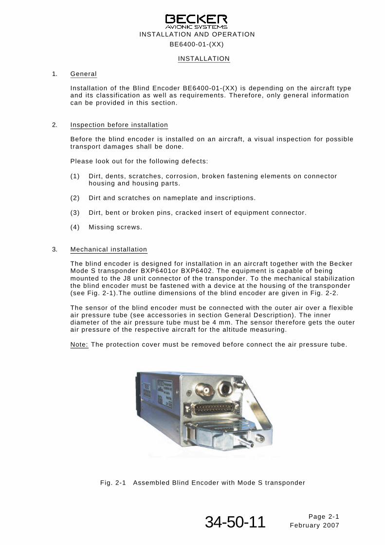
The blind encoder is designed for installation in an aircraft together with the BeckerMode S transponder BXP6401or BXP6402. The equipment is capable of beingmounted to the J8 unit connector of the transponder. To the mechanical stabil ization the blind encoder must be fastened with a device at the housing of the transponder(see Fig. 2-1).The outl ine dimensions of the blind encoder are given in Fig. 2-2.
The sensor of the blind encoder must be connected with the outer air over a flexibleair pressure tube (see accessories in section General Description). The innerdiameter of the air pressure tube must be 4 mm. The sensor therefore gets the outer air pressure of the respective aircraft for the alt itude measuring.
Note: The protection cover must be removed before connect the air pressure tube.
Fig. 2-1 Assembled Blind Encoder with Mode S transponder
IN STAL LA TI ON AND OPE RA TI ON
BE6400-01-(XX)
Page 2-134-50-11 February 2007
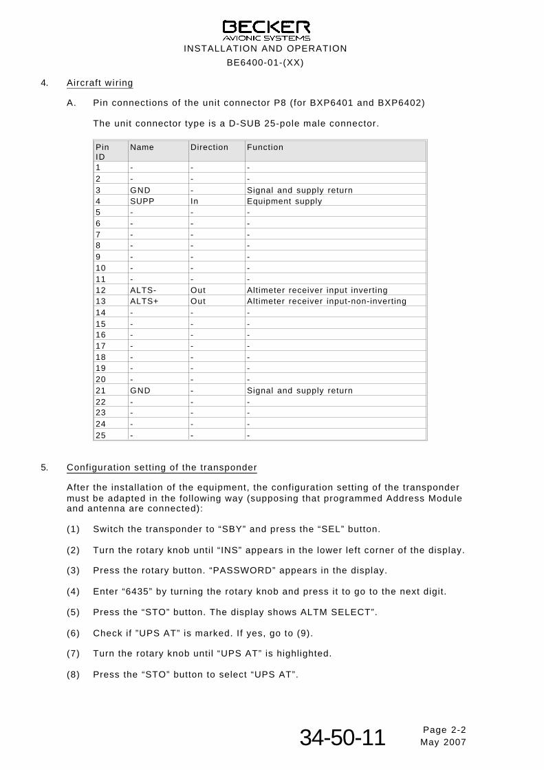
4. Air craft wi ring
A. Pin connections of the unit connector P8 (for BXP6401 and BXP6402)
The unit con nec tor type is a D-SUB 25-pole male connector.
Pin ID
Name Direction Function
1 - - -2 - - -3 GND - Signal and supply return4 SUPP In Equipment supply5 - - -6 - - -7 - - -8 - - -9 - - -10 - - -11 - - -12 ALTS- Out Altimeter receiver input inverting13 ALTS+ Out Altimeter receiver input-non-inverting14 - - -15 - - -16 - - -17 - - -18 - - -19 - - -20 - - -21 GND - Signal and supply return22 - - -23 - - -24 - - -25 - - -
5. Configuration setting of the transponder
After the installation of the equipment, the configuration setting of the transpondermust be adapted in the following way (supposing that programmed Address Moduleand antenna are connected):
(1) Switch the transponder to “SBY” and press the “SEL” button.
(2) Turn the rotary knob unti l “INS” appears in the lower left corner of the display.
(3) Press the rotary button. “PASSWORD” appears in the display.
(4) Enter “6435” by turning the rotary knob and press it to go to the next digit.
(5) Press the “STO” button. The display shows ALTM SELECT”.
(6) Check if ”UPS AT” is marked. If yes, go to (9).
(7) Turn the rotary knob unti l “UPS AT” is highlighted.
(8) Press the “STO” button to select “UPS AT”.
INSTALLATION AND OPERATION
BE6400-01-(XX)
Page 2-234-50-11 May 2007
(9) Press the rotary button unti l “SPECIALS” appears in the display.
(10) Check if “ALTM HIGH RESOL” is marked. If yes, go to (13).
(11) Turn the rotary button to select “ALTM HIGH RESOL”.
(12) Press the “STO” button to set high resolution.
(13) Press the rotary button unti l “ERROR LATCHES” appears in the display.
(14) Turn the rotary button to select “CLEAR LATCHES”.
(15) Press the “STO” button to clear the error latches.
(16) Press the SEL” button to leave the menu.
Configuration is complete now.
6. Chec king af ter in stal la t i on
A. Ge ne ral
Af ter the in stal la t i on, check the blind encoder in con juncti on with the corres-ponding transponder to en su re sa tis fac to ry ope ra ti on of the equipment.
B. Pre-fl ight check
Switch the Mode S transponder to “ALT” and check the correct f l ight level isdisplayed.
IN STAL LA TI ON AND OPE RA TI ON
BE6400-01-(XX)
Page 2-334-50-11 May 2007
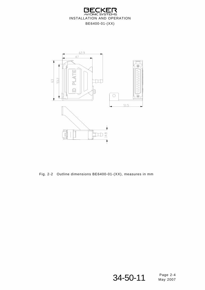
Fig. 2-2 Outl ine dimensions BE6400-01-(XX), measures in mm
INSTALLATION AND OPERATION
BE6400-01-(XX)
Page 2-434-50-11 May 2007
TAB LE OF CON TENTS
OPE RA TI ON Page
1. Operating instructions 3-1
2. Flight level indication 3-1
3. Behavior in the fault case 3-1
4. Ckeck the blind encoder 3-1
INSTALLATION AND OPE RA TI ON
BE6401-01-(XX)
Page III -I34-50-11 August 2006

BLANK
INSTALLATION AND OPERATION
BE6400-01-(XX)
Page III-II34-50-11 August 2006
OPE RA TI ON
1. Operating instructions
A. The operation of the Blind Encoder is controlled by the Becker Mode S trans- ponder BXP6401 or BXP6402.
B. Place the Mode S transponder in the altitude reporting mode to transmit the alt i tude data. Blind encoder which transmit RS-422 data provide continuousdata to RS-422 devices.
C. The start t ime of alt i tude reporting is ≤ 1.5 seconds.
2. Flight level indication
The altitude fl ight level is indicated in the bottom row of the Mode S transponderdisplay (altitude = FL x 100 in ft).
Faulty measurings of the blind encoder are displayed in the bottom row by “---” indi-cation instead of altitude reports.
3. Behavior in the fault case
In case of a failure the alt itude indication has to be turned off, i .e. switch the ModeS transponder to ON using the mode switch.
The pilot must make up, whether he can fly on without alt i tude information, orwhether he must leave the corresponding airspace.
4. Check the blind encoder
The blind encoder has to be checked for function and data retention in the contextof the annual check of the aircraft. If at this deviations are stated, then the blindencoder must be calibrated or overhauled in the manufacturer factory.
INSTALLATION AND OPERATION
BE6400-01-(XX)
Page 3-134-50-11 August 2006

BLANK
INSTALLATION AND OPERATION
BE6400-01-(XX)
Page 3-234-50-11 August 2006