Embed Size (px)
Citation preview
7/29/2019 Bldg_Reg_2006
http://slidepdf.com/reader/full/bldgreg2006 1/86
Fire safety
The Building Regulations 2000
B1 Means of warning and escapeB2 Internal fire spread (linings)
B3 Internal fire spread (structure)
B4 External fire spread
B5 Access and facilities for the fire
VOLUME 1 – DWELLINGHOUSES
APPROVED DOCUMENT
Coming into effect April 2007
7/29/2019 Bldg_Reg_2006
http://slidepdf.com/reader/full/bldgreg2006 2/86
VOLUME 1
MAIN CHANGES IN THE
2006 EDITIONThis edition of Approved Document B, Fire safety,replaces the 2000 edition. The main changes are:
General
a. Approved Document B: The ApprovedDocument has been split into two volumes. Volume 1 deals with dwellinghouses, Volume 2deals with buildings other than dwellinghouses.
Wherever possible the guidance in Volume 1has been tailored and simplified to be moredirectly relevant to dwellinghouses.
Introduction
b. Certification Schemes: Suitable schemesmay be accepted by Building Control Bodiesas evidence of compliance.
c. Residential Sprinklers: The use of sprinklersystems in accordance with BS 9251:2005is recognised.
d. Adult Placements: Reference is made tothe code of practice for fire safety in adultplacements.
B1
e. Fire Alarms: The guidance on smoke alarmshas been amended such that alarms should beinstalled in accordance with BS 5839- 6:2004.
Simple guidance has been retained, in theform of a commentary on this standard, sothat most users of the Approved Documentwill not necessarily need to obtain a copy ofthe standard.
All smoke alarms should have a standbypower supply.
Where a dwellinghouse is extendedsmoke alarms should be provided in thecirculation spaces.
f. Means of escape: The guidance on meansof escape has been restructured to make it
vi. Guidance on the appreplacement window
vii. Guidance on the usesystems in houses wstairways is given.
B3
g. Integral Garages: The pfloor has been included the 100mm step betweeand integral garages.
h. Compartmentation: Gu
junction between comparoofs has been clarified
i. Cavity Barriers: Windoware only suitable for usethey are constructed of appropriate thickness.
B4
j. Roof Coverings: The gucoverings incorporates tsystem of classification 13501-5:2005.
B5
k. Vehicle Access: There sa pump appliance to witwithin a dwellinghouse.
Appendix Bl. Self-Closing Devices: O
between a dwellinghousgarage, fire doors need self closing devices.
7/29/2019 Bldg_Reg_2006
http://slidepdf.com/reader/full/bldgreg2006 3/86
Use o guidance 4
The Approved Documents 4
Limitation on requirements 4
Materials and workmanship 4
Interaction with other legislation 5
General introduction: Fire saety 8
Scope 8
Arrangement o sections 8
Building maintenance and the provisiono inormation 8
Property protection 9
Independent schemes o certicationand accreditation 9
Residential sprinklers 9
Inclusive design 0
Material alteration 0
Alternative approaches 0
B1 Means o warning and escape– The Requirement 2
B1 Guidance 3
Perormance 3
Introduction 3
Analysis o the problem 3
Security 4
General 4
B1 Section 1: Fire detection andre alarm systems 5
Introduction 5
General 5
Large houses 5
Provisions or escapmore than 4.5m abo
General provisions
Work on existing hou
B2 Internal re spre– The Requirement
B2 GuidancePerormance
Introduction
B2 Section 3: Wall a
Classication o linin
Variations and speci
Thermoplastic mater
B3 Internal re spre– The Requirement
B3 Guidance
Perormance
Introduction
B3 Section 4: Loado structure
Introduction
Fire resistance stand
B3 Section 5: Comp
Introduction
Provision o comparConstruction o comcompartment foors
Openings in compar
B3 Section 6: Conc
Contents
PAGE
7/29/2019 Bldg_Reg_2006
http://slidepdf.com/reader/full/bldgreg2006 4/86
B4 External re spread– The Requirement 4
B4 Guidance 42
Perormance 42
Introduction 42
B4 Section 8: Construction oexternal walls 43
Introduction 43
Fire resistance standard 43
External suraces 43
B4 Section 9: Space separation 44
Introduction 44
Boundaries 44
Unprotected areas 45
Methods or calculating acceptableunprotected area 46
B4 Section 10: Roo coverings 49
Introduction 49
Classication o perormance 49
Separation distances 49
B5 Access and acilities orthe Fire and Rescue Service– The Requirement 52
B5 Guidance 53
Perormance 53
Introduction 53
B5 Section 11: Vehicle access 54
Introduction 54
Design o access routes and hard-standings 54
Appendices
Appendix A: Perormance o materials,
Appendix B: Fire doors
Appendix C: Methods o m
Appendix D: Purpose grou
Appendix E: Denitions
Appendix F: Standards anpublications reerred to
Diagrams
B1
. Means o escape ro
2. Alternative arrangem
3. Fire separation in houthan one foor over 4ground level
4. Ground or basementan enclosed space
5. Gallery foors with no
6. Alternative cavity barin roo space over prin a house with a fooabove ground level
7. Fire resistance o are
external stairs
B2
8. Lighting diuser in re
9. Layout restrictions onroofights, TP(b) rooflighting diusers
B3
0. Separation between dwellinghouse
. Junction o compartmwith roo
2. Interrupting conceale( iti )
PAGE
B CONTENTS
7/29/2019 Bldg_Reg_2006
http://slidepdf.com/reader/full/bldgreg2006 5/86
20. Unprotected areas which may bedisregarded in assessing the separation
distance rom the boundary 472. The eect o a canopy on
separation distance 47
22. Permitted unprotected areas orMethod 48
23. Limitations on spacing and size oplastic roofights having a Class 3(National Class) or Class D-s3,
d2 (European class) or TP(b)lower surace 49
B5
24. Turning acilities 54
Appendix C
C. Height o top storey in building 68
Tables
B2
. Classication o linings 26
2. Limitations applied to thermoplasticroofights and lighting diusers insuspended ceilings and Class 3plastic roofights 28
B3
3. Maximum nominal internal diameter opipes passing through a re separatingelement 38
B4
4. Permitted unprotected areas orMethod 2 48
5. Limitations on roo coverings 50
6. Class 3 (National class) or ClassD-s3, d2 (European class) plasticroofights: limitations on use andboundary distance 5
7 TP( ) d TP(b) l ti fi ht
A4. Limitations onuninsulated g
on escape rou A5. Notional desig
A6. Use and dennon-combust
A7. Use and denlimited combu
A8. Typical peroro some gene
and products
B. Provisions or
D. Classication
PAGE
CONTENTS
7/29/2019 Bldg_Reg_2006
http://slidepdf.com/reader/full/bldgreg2006 6/86
THE APPROVED DOCUMENTS
This document is one o a series that has beenapproved and issued by the Secretary o Stateor the purpose o providing practical guidancewith respect to the requirements o Schedule to and Regulation 7 o the Building Regulations2000 (SI 2000/253) or England and Wales.
At the back o this document is a list oall the documents that have been approvedand issued by the Secretary o State or
this purpose.
The Approved Documents are intended toprovide guidance or some o the more commonbuilding situations. However, there may well bealternative ways o achieving compliance withthe requirements.
Thus there is no obligation to adopt any particular solution contained in an Approved
Document i you preer to meet the relevantrequirement in some other way.
Other requirements
The guidance contained in an ApprovedDocument relates only to the particularrequirements o the Regulations which thatdocument addresses. The building work will alsohave to comply with the Requirements o anyother relevant paragraphs in Schedule to theRegulations.
There are Approved Documents which giveguidance on each o the other requirements inSchedule and on Regulation 7.
LIMITATION ON REQUIREMENTS
In accordance with Regulation 8, therequirements in Parts A to D, F to K, N and P(except or paragraphs H2 and J6) o Schedule to the Building Regulations do not requireanything to be done except or the purpose osecuring reasonable standards o health andsaety or persons in or about buildings (andany others who may be aected by buildings ormatters connected with buildings) This is one
MATERIALS AND W
Any building work which is srequirements imposed by SBuilding Regulations shouldRegulation 7, be carried outand in a workmanlike manne
You may show that you havRegulation 7 in a number othe appropriate use o a promarking in accordance with
Products Directive (89/06/ Voltage Directive (73/23/EEC93/68/EEC)2 and the EMC DEEC)3, as amended by the C(93/68/EEC)4, or a product cappropriate technical speciin those Directives), a Britishalternative national technicaMember State o the Europe
or o another State signatoryon the European Economic provides an equivalent levelprotection, or a product covor European certicate issueTechnical Approval Issuing bconditions o use are in accterms o the certicate.
You will nd urther guidanc
Document supporting Reguand workmanship.
Independent certiication
There are many UK productschemes. Such schemes cethe requirements o a recogwhich is appropriate to the pmaterial is to be used. Matecertied may still conorm to
Many certication bodies wschemes are accredited by Accreditation Service (UKAS
Use o guidanceB

7/29/2019 Bldg_Reg_2006
http://slidepdf.com/reader/full/bldgreg2006 7/86
Since the re perormance o a product,component or structure is dependent uponsatisactory site installation and maintenance,independent schemes o certication and
accreditation o installers and maintenancerms o such will provide condence inthe appropriate standard o workmanshipbeing provided.
Building Control Bodies may accept thecertication o products, components, materialsor structures under such schemes as evidence ocompliance with the relevant standard. Similarly,Building Control Bodies may accept the certication
o the installation or maintenance o products,components, materials or structures under suchschemes as evidence o compliance with therelevant standard. Nonetheless, a BuildingControl Body will wish to establish, in advanceo the work, that any such scheme is adequateor the purposes o the Building Regulations.
Technical speciications
Building Regulations are made or specicpurposes, such as health and saety, energyconservation and the welare and convenienceo people. Standards and technical approvals arerelevant guidance to the extent that they relateto these considerations. However, they may alsoaddress other aspects o perormance such asserviceability, or aspects which, although theyrelate to health and saety, are not covered bythe Regulations.
When an Approved Document makes reerenceto a named standard, the relevant version othe standard is the one listed at the end o thepublication. However, i this version o thestandard has been revised or updated by theissuing standards body, the new version maybe used as a source o guidance provided itcontinues to address the relevant requirementso the Regulations.
The appropriate use o a product which complieswith a European Technical Approval as dened inthe Construction Products Directive will meet therelevant requirements.
The Department intends to issue periodicamendments to its Approved Documents
INTERACTION
LEGISLATION
Houses in multiple
This guidance may adesign and construcconsidered to be ‘ho(HMOs), as dened iproviding there are nin any sel-containedo HMOs is typically Authority who may rover and above this guidance on the assre and preventive mcontained in the HouRating System OperFebruary 2006 (ISBN
The Workplace (HeRegulations 1992
The Workplace (Heal
Regulations 1992 cowhich aect buildingrequirements are nowRegulations but or Workplace health, saWorkplace (Health, Sa1992, Approved CodThe Health and Saepublished by HMSO
The Workplace (HealRegulations 1992 apo fats and similar bcleaners, wardens anto work in these comrequirements o the covered by this Part the provisions may ssituations described
the Workplace ReguThe Construction (DRegulations 2006
The purpose o this Aprovide guidance onor the completed buth i k d i
USE OF GUIDANCE
7/29/2019 Bldg_Reg_2006
http://slidepdf.com/reader/full/bldgreg2006 8/86
The Construction Products Directive
The Construction Products Directive (CPD) is oneo the ‘New Approach’ Directives, which seek toremove technical barriers to trade within the
European Economic Area (EEA) as part o themove to complete the Single Market. The EEA comprises the European Community and thosestates in the European Free Trade Association(other than Switzerland).
The intention o the CPD is to replace existingnational standards and technical approvalswith a single set o European-wide technicalspecications or construction products (i.e.
harmonised European standards or EuropeanTechnical Approvals). Any manuacturer whoseproducts have CE marking showing that theyare specied according to European technicalspecications cannot have these productsreused entry to EEA markets on technicalgrounds. In the UK, the CPD was implementedby the Construction Products Regulations, whichcame into orce on 27 December 99 and were
amended on January 995 by the ConstructionProducts (Amendment) Regulations 994.
This document reers to, and utilises within itsguidance, a large number o British Standards,in relation to Codes o Practice and re testmethods (typically the BS 476 series odocuments). In order to acilitate harmonisationand the use o the new technical specicationsand their supporting European test standards,
guidance is also given on the classication oproducts in accordance with those standards.
Guidance is given or the appropriate use and/orspecication o a product to which one or moreo the ollowing apply:
. a product bearing CE marking in accordancewith the Construction Products Directive(89/06/EEC) as amended by the CE markingDirective (93/68/EEC);
2. a product tested and classied in accordancewith the European Standards (BS EN)reerred to in the Commission Decision2000/47/EC and/or Commission Decision2000/367/EC2;
3. a product complying with an appropriate
relation to the European re tclearly dened.
As new inormation becomeurther harmonised Europea
to this document are publiswill be made available.
Designation o standards
The designation o ‘xxxx’ is reerred to or standards thapublished. The latest versionbe used provided that it conrelevant requirements o the
Commission guidance pap
The ollowing guidance papDecisions are directly relevaunder the Construction Prod
Guidance paper G
The European classication sto re perormance o const
Guidance paper J
Transitional arrangements uProducts Directive.
Commission Decision o 8 F(2000/47/EC) implementing89/06/EEC as regards the reaction to re perormance o
Commission Decision o 3 MEC) implementing Council Das regards the classicationto re perormance o constconstruction works and part
Commission Decision o 26(2000/605/EC) amending Deestablishing the list o produClasses A ‘No contribution t
or in Decision 94/6/EC im Article 20 o Council Directivon construction products.
Corrigenda – Corrigendum tDecision 2000/47/EC o 8 implementing Council Direcregards the classication o
B USE OF GUIDANCE
7/29/2019 Bldg_Reg_2006
http://slidepdf.com/reader/full/bldgreg2006 9/86
Environmental Protection
Requirements under Part B o the BuildingRegulations and the guidance in this ApprovedDocument are made or the purpose o ensuring
the health and saety o people in and aroundbuildings.
The Environment Agency publishes guidance onthe design and construction o buildings or thepurpose o protecting the environment. Thisincludes Pollution Prevention Guidelines (PPG8)on Managing Fire Water and Major Spillages,which seeks to minimise the eects o waterrun-o rom reghting. It is aimed at medium
to large (and small, high-risk) commercial andindustrial sites and sets out requirements orthe construction o containment areas orcontaminated water and such other measures.
It should be noted that compliance with theBuilding Regulations does not depend uponcompliance with other such guidance.
USE OF GUIDANCE
7/29/2019 Bldg_Reg_2006
http://slidepdf.com/reader/full/bldgreg2006 10/86
Scope
0.1 Approved Document B (Fire saety) hasbeen published in two volumes. Volume dealssolely with dwellinghouses (see Appendix E andBuilding Regulation 2()), while Volume 2 dealswith all other types o building covered by theBuilding Regulations.
Where very large (over 8m in height) or unusualdwellinghouses are proposed some o theguidance in Volume 2 may be needed to
supplement that given by Volume .
Arrangement o sections
0.2 The unctional requirements B to B5 oSchedule o the Building Regulations are dealtwith separately in one or more Sections. Therequirement is reproduced at the start o therelevant Sections, ollowed by an introduction
to the subject.0.3 The provisions set out in this documentdeal with dierent aspects o re saety, with theollowing aims:
B1: To ensure satisactory provision omeans o giving an alarm o re and asatisactory standard o means o escapeor persons in the event o re in a building.
B2: To ensure re spread over theinternal linings o buildings is inhibited.
B3: To ensure the stability o buildingsin the event o re; to ensure that there is asucient degree o re separation withinbuildings and between adjoining buildings;to provide automatic re suppressionwhere necessary; and to inhibit the unseenspread o re and smoke in concealedspaces in buildings.
B4: To ensure external walls and rooshave adequate resistance to the spread ore over the external envelope, and thatspread o re rom one building to anotheris restricted.
B5: To ensure satisactory access
where variations in the standbeing considered. A higher
o the requirements may be o one or more o the other guidance in the document aconsidered as a package aiacceptable standard o re s
Appendices: provisions coone o Part B’s requiremen
0.5 Guidance on matters
than one o the Sections is i Appendices, covering the o
Appendix A – re perorproducts
Appendix B – provisions
Appendix C – methods o
Appendix D – a classicgroups
Appendix E – denitions
Appendix F – Standardspublicatio
Fire perormance o materand structures
0.6 Much o the guidancedocument is given in terms
relation to standard re testdrawn together in Appendixis made where appropriate. protection systems, reerenstandards or system designStandards reerred to are lis
Fire doors
0.7 Guidance in respect
in Appendix B.
Methods o measurement
0.8 Some orm o measupart o much o the guidancand methods are set out in A
General introduction: Fire saety B
7/29/2019 Bldg_Reg_2006
http://slidepdf.com/reader/full/bldgreg2006 11/86
measures incorporated into the design o adwellinghouse are adequately maintained.Building Regulations do not impose anyrequirements on the management o a building.
However, the eventual owners and occupiersshould be provided with sucient inormationto operate, maintain and use the building inreasonable saety.
For individual dwellinghouses, basic advice on theproper use and maintenance o systems providedin the building, such as emergency egress windows,re doors, smoke alarms, sprinklers etc., can helpto ensure that these systems are maintained and
kept available or use. Householders should alsobe made aware that unauthorised materialalterations (see paragraph 0.20) may leave themliable to prosecution.
In providing re protection o any kind indwellinghouses, it should be recognised thatmeasures which signicantly interere with theday-to-day convenience o the occupants maybe less reliable in the long term.
Property protection
0.12 There are oten many stakeholders,including insurers, who have a valid interestin the re protection measures which areincorporated into a building’s design. To ensurethat the most eective re protection measuresare applied which are appropriate to the specicproperty, early consultation with the main
stakeholders is essential. Failure to consult withstakeholders at an early stage could result inadditional measures being required atercompletion, the use o the building beingrestricted, or insurance premiums and/ordeductibles being increased.
Building Regulations are intended to ensure thata reasonable standard o lie saety is providedin case o re. The protection o property,
including the building itsel, oten requiresadditional measures and insurers will, in general,seek their own higher standards beore acceptingthe insurance risk.
Guidance or asset protection in the Civil andDeence Estates is given in the Crown FireSt d d bli h d b th P t Ad i
upon satisactory sitmaintenance, indepecertication and accand maintenance rm
condence in the apworkmanship being
Condence that the can be achieved willuse o a system, matwhich is provided unproduct conormity caccreditation o insta
Third party accredite
certication schemeo identiying materiaproducts or structurethat they have the rebut additionally provsystems, materials, pactually supplied arespecication or desi
Third party accredita
materials, products omeans o ensuring thconducted by knowlappropriate standardreliability o the antic
Many certication boschemes are accred
0.15 Building Cont
certication o produor structures under scompliance with the Building Control Bodcertication o the inproducts, componenunder such schemeswith the relevant staBuilding Control Bodadvance o the work
adequate or the purRegulations.
Residential sp
0.16 Sprinkler systdwellinghouses can
GENERAL INTRODUCTION: FIRE SAFETY
7/29/2019 Bldg_Reg_2006
http://slidepdf.com/reader/full/bldgreg2006 12/86
throughout the building. However, where thesprinklers are being installed as a compensatoryeature to address a specic risk or hazard it maybe acceptable to protect only part o a building.
Further guidance can also be ound in Sprinklersor Saety: Use and Benets o IncorporatingSprinklers in Buildings and Structures, BAFSA (2006) ISBN: 0 95526 280 .
0.18 There are many alternative or innovativere suppression systems available. Where theseare used it is necessary to ensure that suchsystems have been designed and tested oruse in domestic buildings and are t or their
intended purpose.
Inclusive design
0.19 The re saety aspects o the BuildingRegulations are made or securing reasonablestandards o health and saety o persons in andabout buildings. This is intended to include allpeople including people with disabilities. The
provisions set out in this Approved Document areconsidered to be a reasonable standard or mostbuildings. However, there may be some peoplewhose specic needs are not addressed. In somesituations additional measures may be needed toaccommodate these needs. This should be doneon a case by case basis.
Material alteration
0.20 Under Regulation 3, the term “materialalteration” is dened by reerence to a list o“relevant requirements” o Schedule to theBuilding Regulations. That list includes therequirements o Parts B, B3, B4 and B5. Thismeans that an alteration which, at any stage othe work, results in a building being lesssatisactory than it was beore in relation tocompliance with the requirements o Parts B,
B3, B4 or B5 is a material alteration, and isthereore controlled by Regulation 4 as it is classedas “building work”. Regulation 4() requires thatany building work carried out in relation to amaterial alteration complies with the applicablerequirements o Schedule to the Regulations,while Regulation 4(2) requires that once thatb ildi k h b l t d th b ildi
I other codes or guides arerelevant recommendations csaety in the particular publiollowed, rather than a mixtu
and provisions in the relevan Approved Document. Howecircumstances where it is nepublication to supplement a
Guidance documents intendassessing re saety in exisoten include provisions whthan those set out in this Apother standards applicable t
such, these documents are appropriate or use where bcontrolled by the Regulation
Registered group homes
0.22 Depending on the naand their management needsto treat an unsupervised groto six residents as an ordinaHowever, because such plaregistered, the registration aconsulted to establish whetadditional re saety measuwill require.
Where an existing house o to be put to use as an unsupor not more than 6 mental hit should be regarded as a Pbuilding i the means o escaccordance with HTM 88: Gu in NHS housing in the comm handicapped (or mentally ill)building is new, it may be mregard it as being in Purpos
Adult placements
0.23 Where a dwellinghoupurposes o an Adult Placem
ulls the criteria o the AduSchemes (England) Regulat2070) and where no building guidance in the joint code oby the National Association Services (www.naaps.co.ukto satisy Part B o the Build
B GENERAL INTRODUCTION: FIRE SAFETY
7/29/2019 Bldg_Reg_2006
http://slidepdf.com/reader/full/bldgreg2006 13/86
buildings. Fire saety engineering may also besuitable or solving a problem with an aspect othe building design which otherwise ollows theprovisions in this document.
British Standard BS 7974:200 Application o re saety engineering principles to the design o buildings and supporting published documents(PDs) provide a ramework and guidance on thedesign and assessment o re saety measuresin buildings. Following the discipline o BS 7974should enable designers and Building ControlBodies to be aware o the relevant issues, theneed to consider the complete re saety system,
and to ollow a disciplined analytical ramework.0.26 Factors that should be taken intoaccount include:
a. the anticipated probability o a re occurring;
b. the anticipated re severity;
c. the ability o a structure to resist the spreado re and smoke; and
d. the consequential danger to people in andaround the building.
0.27 A wide variety o measures could beconsidered and incorporated to a greater or lesserextent, as appropriate in the circumstances.These include:
a. the adequacy o means to prevent re;
b. early re warning by an automatic detection
and warning system;c. the standard o means o escape;
d. provision o smoke control;
e. control o the rate o growth o a re;
. the adequacy o the structure to resist theeects o a re;
g. the degree o re containment;
h. re separation between buildings or partso buildings;
i. the standard o active measures or reextinguishment or control;
j. acilities to assist the re and rescue service;
k th il bilit t i t
Buildings o speciainterest
0.29 Some variatioin this document ma
Part B applies to exiin buildings o speciainterest, where adhethis document mightIn such cases it wouaccount a range o which are dealt with o which are not addset these against an
and risk peculiar to t
GENERAL INTRODUCTION: FIRE SAFETY
7/29/2019 Bldg_Reg_2006
http://slidepdf.com/reader/full/bldgreg2006 14/86
This Approved Document deals with the ollowingRequirement rom Part B o Schedule to the
Building Regulations 2000 (as amended).
Requirement Limitsonapplication
Means of warning and escape
B1. The building shall be designed and constructed so that
there are appropriate provisions for the early warning of
fire, and appropriate means of escape in case of fire from
the building to a place of safety outside the building capable
of being safely and effectively used at all material times.
Requirement B1 does no
provided under Section 3
1952 (power to provide p
The RequirementB1 MEANS OF WARNING AND ESCAPE
7/29/2019 Bldg_Reg_2006
http://slidepdf.com/reader/full/bldgreg2006 15/86
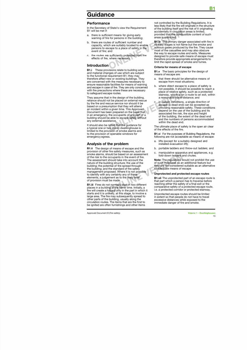
Perormance
In the Secretary o State’s view the RequirementB will be met i:
a. there is sucient means or giving earlywarning o re or persons in the building;
b. there are routes o sucient number andcapacity, which are suitably located to enablepersons to escape to a place o saety in theevent o re; and
c. the routes are suciently protected rom theeects o re, where necessary.
Introduction
B1.i These provisions relate to building workand material changes o use which are subjectto the unctional requirement B; they maythereore aect new or existing buildings. Theyare concerned with the measures necessary toensure reasonable acilities or means o warningand escape in case o re. They are only concernedwith re precautions where these are necessaryto saeguard escape routes.
They assume that in the design o the building,reliance should not be placed on external rescueby the re and rescue service nor should it bebased on a presumption that they will attendan incident within a given time. This ApprovedDocument has been prepared on the basis that,in an emergency, the occupants o any part o abuilding should be able to escape saely withoutany external assistance.
It should also be noted that the guidance ora typical one or two storey dwellinghouse islimited to the provision o smoke alarms andto the provision o openable windows oremergency egress.
Analysis o the problem
B1.ii The design o means o escape and theprovision o other re saety measures, such assmoke alarms, should be based on an assessmento the risk to the occupants in the event o re
not controlled by theless likely that the re
o the building itsel accidentally in circulprovided that the coareas is restricted.
B1.iv The primary dits early stages is nonoxious gases produmost o the casualtiethe way to escape ro
designed to provide thereore provide aplimit the rapid spread
Criteria or means o
B1.v The basic prinmeans o escape are
a. that there shouldescape rom mos
b. where direct escnot possible, it splace o relative stairway, which ia reasonable trav
c. in certain conditiescape (a dead eproviding reason
depend on the uassociated re rio the building, tand the numberswithin the dead e
The ultimate place oo the eects o the
B1.vi For the purposollowing are not acc
a. lits (except or ainstalled evacuat
b. portable ladders
c. manipulative appold-down ladde
Guidance
7/29/2019 Bldg_Reg_2006
http://slidepdf.com/reader/full/bldgreg2006 16/86
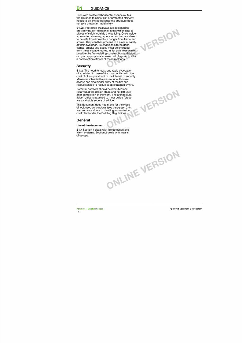
Even with protected horizontal escape routesthe distance to a nal exit or protected stairwayneeds to be limited because the structure doesnot give protection indenitely.
B1.viii Protected stairways are designed toprovide virtually ‘re sterile’ areas which lead toplaces o saety outside the building. Once insidea protected stairway, a person can be consideredto be sae rom immediate danger rom fame andsmoke. They can then proceed to a place o saetyat their own pace. To enable this to be done,fames, smoke and gases must be excludedrom these escape routes, as ar as is reasonablypossible, by re-resisting construction and doorsor by an appropriate smoke control system, or bya combination o both o these methods.
Security
B1.ix The need or easy and rapid evacuationo a building in case o re may confict with thecontrol o entry and exit in the interest o security.Measures intended to prevent unauthorised
access can also hinder entry o the re andrescue service to rescue people trapped by re.
Potential conficts should be identied andresolved at the design stage and not let untilater completion o the work. The architecturalliaison ocers attached to most police orcesare a valuable source o advice.
This document does not intend or the types
o lock used on windows (see paragraph 2.8)and entrance doors to dwellinghouses to becontrolled under the Building Regulations.
General
Use o the document
B1.x Section deals with re detection andalarm systems. Section 2 deals with means
o escape.
B1 GUIDANCE
7/29/2019 Bldg_Reg_2006
http://slidepdf.com/reader/full/bldgreg2006 17/86
Introduction1.1 Provisions are made in this section orsuitable arrangements to be made in dwellinghousesto give early warning in the event o re.
General
1.2 The installation o smoke alarms, or
automatic re detection and alarm systemscan signicantly increase the level o saetyby automatically giving an early warning o re.The ollowing guidance is appropriate or mostdwellinghouses. However, where it is knownthat the occupants o a proposed dwellinghouseare at a special risk rom re, it may be moreappropriate to provide a higher standard oprotection, e.g. additional detectors.
1.3 All new dwellinghouses should be providedwith a re detection and re alarm system inaccordance with the relevant recommendationso BS 5839-6:2004 to at least a Grade DCategory LD3 standard.
1.4 The smoke and heat alarms should bemains-operated and conorm to BS 5446-:2000or BS 5446-2:2003, respectively: Fire detectionand re alarm devices or dwellinghouses,
Part Specication or smoke alarms; or Part 2Specication or heat alarms. They should havea standby power supply, such as a battery (eitherrechargeable or non-rechargeable) or capacitor.More inormation on power supplies is given inclause 5 o BS 5839-6:2004.
Note: BS 5446- covers smoke alarms based onionization chamber smoke detectors and optical(photo-electric) smoke detectors. The dierent
types o detector respond dierently tosmouldering and ast-faming res. Either typeo detector is generally suitable. However, thechoice o detector type should, i possible,take into account the type o re that might beexpected and the need to avoid alse alarms.Optical detectors tend to be less aected byl l l ‘i i ibl ’ ti l h
1.7 A large dwelli(excluding basementwith a Grade A Categin BS 5839-6:2004, waccordance with theBS 5839-:2002 or
Material altera
1.8 Where new haabove the ground foprovided at ground fexit rom the new rooalarm system shouldshould be provided ithe dwellinghouse in.0 to .8 to ensurnew rooms are warnimpede their escape
Sheltered hous
1.9 The detectionhousing scheme withshould have a connepoint (or alarm receivperson in charge is adetected in one o th
can identiy the dweThese provisions areto the common partsdevelopment, such asheltered accommodOther residential purDocument B Volume
Positioning o
heat alarms1.10 Detailed guidainstallation o re detin dwellinghouses is However, the ollowito most common situ
Section 1: Fire detection and irealarm systems
7/29/2019 Bldg_Reg_2006
http://slidepdf.com/reader/full/bldgreg2006 18/86
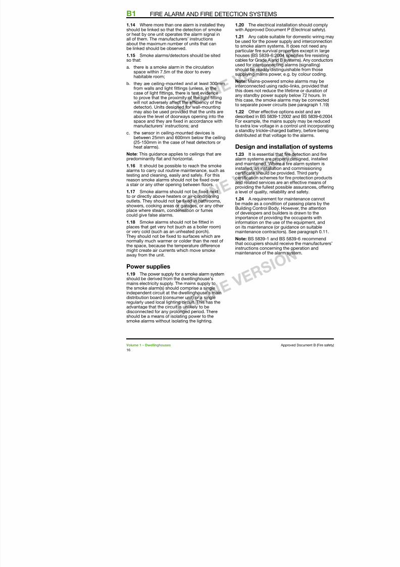
1.14 Where more than one alarm is installed theyshould be linked so that the detection o smokeor heat by one unit operates the alarm signal inall o them. The manuacturers’ instructionsabout the maximum number o units that canbe linked should be observed.
1.15 Smoke alarms/detectors should be sitedso that:
a. there is a smoke alarm in the circulationspace within 7.5m o the door to everyhabitable room;
b. they are ceiling-mounted and at least 300mmrom walls and light ttings (unless, in thecase o light ttings, there is test evidenceto prove that the proximity o the light ttingwill not adversely aect the eciency o thedetector). Units designed or wall-mountingmay also be used provided that the units areabove the level o doorways opening into thespace and they are xed in accordance withmanuacturers’ instructions; and
c. the sensor in ceiling-mounted devices isbetween 25mm and 600mm below the ceiling(25-50mm in the case o heat detectors orheat alarms).
Note: This guidance applies to ceilings that arepredominantly fat and horizontal.
1.16 It should be possible to reach the smokealarms to carry out routine maintenance, such astesting and cleaning, easily and saely. For this
reason smoke alarms should not be xed overa stair or any other opening between foors.
1.17 Smoke alarms should not be xed nextto or directly above heaters or air-conditioningoutlets. They should not be xed in bathrooms,showers, cooking areas or garages, or any otherplace where steam, condensation or umescould give alse alarms.
1.18 Smoke alarms should not be tted inplaces that get very hot (such as a boiler room)or very cold (such as an unheated porch).They should not be xed to suraces which arenormally much warmer or colder than the rest othe space, because the temperature dierencemight create air currents which move smoke
th it
1.20 The electrical installawith Approved Document P
1.21 Any cable suitable obe used or the power suppl
to smoke alarm systems. It particular re survival propehouses (BS 5839-6:2004 spcables or Grade A and B sysused or interconnecting alashould be readily distinguishsupplying mains power, e.g
Note: Mains-powered smokinterconnected using radio-
this does not reduce the lieany standby power supply bthis case, the smoke alarmsto separate power circuits (s
1.22 Other eective optiondescribed in BS 5839-:2002For example, the mains supto extra low voltage in a cona standby trickle-charged b
distributed at that voltage to
Design and installat
1.23 It is essential that realarm systems are properly and maintained. Where a rinstalled, an installation andcerticate should be providecertication schemes or reand related services are an providing the ullest possiblea level o quality, reliability a
1.24 A requirement or mabe made as a condition o pBuilding Control Body. Howo developers and builders iimportance o providing theinormation on the use o thon its maintenance (or guidamaintenance contractors). S
Note: BS 5839- and BS 58that occupiers should receivinstructions concerning the maintenance o the alarm sy
B1 FIRE ALARM AND FIRE DETECTION SYSTEMS
7/29/2019 Bldg_Reg_2006
http://slidepdf.com/reader/full/bldgreg2006 19/86
Introduction
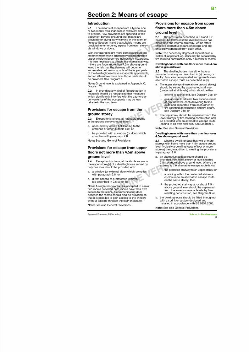
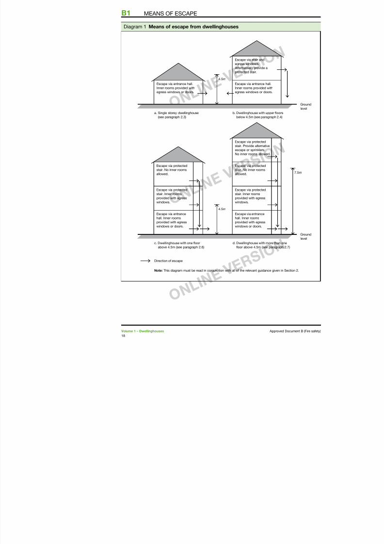
2.1 The means o escape rom a typical oneor two storey dwellinghouse is relatively simpleto provide. Few provisions are specied in thisdocument beyond ensuring that means areprovided or giving early warning in the event ore (see Section ) and that suitable means areprovided or emergency egress rom each storeyvia windows or doors.
With increasing height more complex provisions
are needed because emergency egress throughupper windows becomes increasingly hazardous.It is then necessary to protect the internal stairway.I there are foors more than 7.5m above groundlevel, the risk that the stairway will becomeimpassable beore occupants o the upper partso the dwellinghouse have escaped is appreciable,and an alternative route rom those parts shouldbe provided. See Diagram .
Note: Ground level is explained in Appendix C,Diagram C.
2.2 In providing any kind o re protection inhouses it should be recognised that measureswhich signicantly interere with the day-to-dayconvenience o the occupants may be lessreliable in the long term.
Provisions or escape rom the
ground storey
2.3 Except or kitchens, all habitable roomsin the ground storey should either:
a. open directly onto a hall leading to theentrance or other suitable exit; or
b. be provided with a window (or door) whichcomplies with paragraph 2.8.
Note: See also General Provisions.
Provisions or escape rom upper
loors not more than 4.5m above
ground level
Provisions or
loors more thaground level
2.5 The provisionneed not be ollowedmore than one interneective alternative physically separated
Note: The necessary
matter o judgement, ere-resisting construc
Dwellinghouses witabove ground level
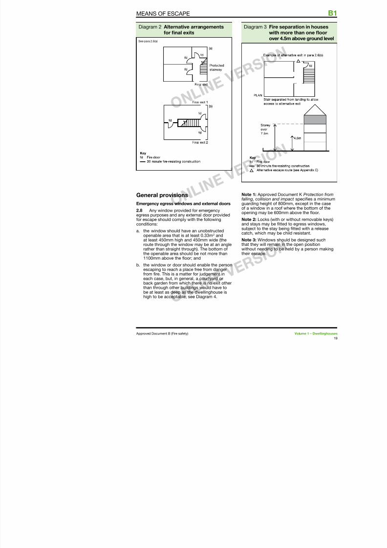
2.6 The dwellinghprotected stairway athe top foor can be alternative escape ro
a. The upper storeysshould be served(protected at all
i. extend to a
ii. give access tat ground levexits and sepre-resisting
see Diagram b. The top storey sh
lower storeys by be provided withleading to its ow
Note: See also Gene
Dwellinghouses wit4.5m above ground
2.7 Where a dwelstoreys with foors mlevel (typically a dwestoreys) then, in addiin paragraph 2.6:
a. an alternative es
Section 2: Means o escape
B1
7/29/2019 Bldg_Reg_2006
http://slidepdf.com/reader/full/bldgreg2006 20/86
B1 MEANS OF ESCAPE
4.5m
4.5m
b. Dwellinghouse with upper flo
below 4.5m (see paragraph 2
a. Single storey dwellinghouse
(see paragraph 2.3)
Escape via protected
stair. No inner rooms
allowed.
Escape via protected
stair. No inner rooms
allowed.
Escape via protected
stair. Provide alternative
escape or sprinklers.
No inner rooms allowed.
Escape via protected
stair. Inner rooms
provided with egress
windows.
Escape via protected
stair. Inner rooms
provided with egress
windows.
Escape via entrance
hall. Inner rooms
provided with egress
windows or doors.
Escape via entrance
hall. Inner rooms
provided with egress
windows or doors.
Escape via stair and
egress windows.
Alternatively provide a
protected stair.
Escape via entrance hall.
Inner rooms provided withegress windows or doors.
Escape via entrance hall.
Inner rooms provided withegress windows or doors.
d Dwellinghouse with more thac Dwellinghouse with one floor
Diagram Means o escape rom dwellinghouses
MEANS OF ESCAPE
7/29/2019 Bldg_Reg_2006
http://slidepdf.com/reader/full/bldgreg2006 21/86
General provisions
Emergency egress windows and external doors
2.8 Any window provided or emergencyegress purposes and any external door providedor escape should comply with the ollowingconditions:
a. the window should have an unobstructedopenable area that is at least 0.33m2 andat least 450mm high and 450mm wide (theroute through the window may be at an angle
Note 1: Approved Dalling, collision and guarding height o 8o a window in a rooopening may be 600
Note 2: Locks (with and stays may be tsubject to the stay bcatch, which may be
Note 3: Windows shthat they will remain
Diagram 2 Alternative arrangementsor nal exits
See para 2.6(a)
Diagram 3 Fire swith
over 4
MEANS OF ESCAPE
B1 MEANS OF ESCAPE
7/29/2019 Bldg_Reg_2006
http://slidepdf.com/reader/full/bldgreg2006 22/86
Inner rooms2.9 A room whose only escape route is throughanother room is termed an inner room and isat risk i a re starts in that other room (accessroom). This situation may arise with open-planlayouts and galleries. Such an arrangement isonly acceptable where the inner room is:
a. a kitchen;
b. a laundry or utility room;c. a dressing room;
d. a bathroom, WC, or shower room;
e. any other room on a foor, not more than4.5m above ground level, provided with anemergency egress window which complieswith paragraph 2.8; or
. a gallery which complies with paragraph 2.2.
Note: A room accessed only via an inner room(an inner-inner room) may be acceptable i itcomplies with the above, not more than one doorseparates the room rom an interlinked smokealarm and none o the access rooms is a kitchen.
Balconies and lat roos2.10 A fat roo orming paescape should comply with th
a. the roo should be part rom which escape is be
b. the route across the roostorey exit or external es
c. the part o the roo ormand its supporting strucany opening within 3m oshould provide 30 minut(see Appendix A, Table A
2.11 Where a balcony or for escape purposes guardiin which case it should mee Approved Document K Protcollision and impact.
B1 MEANS OF ESCAPE
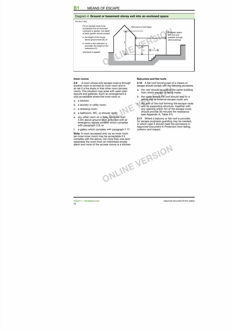
Mid point of roof slopeFor an escape route to be
acceptable into an enclosed
courtyard or garden, the depth
of back garden should exceed:
a. the height of the house
above ground level (X); or
b. where a rear extension is
provided, the height of the
extensions (Y)
whichever is greater.
E
w
p
o
YY
X
X
Diagram 4 Ground or basement storey exit into an enclosed space
See para 2.8(b)
MEANS OF ESCAPE
7/29/2019 Bldg_Reg_2006
http://slidepdf.com/reader/full/bldgreg2006 23/86
Galleries
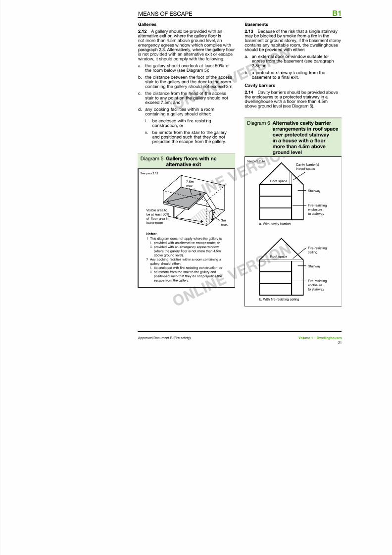
2.12 A gallery should be provided with analternative exit or, where the gallery foor isnot more than 4.5m above ground level, an
emergency egress window which complies withparagraph 2.8. Alternatively, where the gallery fooris not provided with an alternative exit or escapewindow, it should comply with the ollowing;
a. the gallery should overlook at least 50% othe room below (see Diagram 5);
b. the distance between the oot o the accessstair to the gallery and the door to the roomcontaining the gallery should not exceed 3m;
c. the distance rom the head o the accessstair to any point on the gallery should notexceed 7.5m; and
d. any cooking acilities within a roomcontaining a gallery should either:
i. be enclosed with re-resistingconstruction; or
ii. be remote rom the stair to the galleryand positioned such that they do notprejudice the escape rom the gallery.
Basements
2.13 Because o thmay be blocked by sbasement or ground
contains any habitabshould be provided w
a. an external door egress rom the b2.8); or
b. a protected stairbasement to a n
Cavity barriers
2.14 Cavity barriersthe enclosures to a pdwellinghouse with aabove ground level (
MEANS OF ESCAPE
Visible area to
be at least 50%
of floor area in
lower room
7.5m
max
3mmax
1 This diagram does not apply where the gallery is
i. provided with an alternative escape route; or
ii. provided with an emergency egress window
Diagram 5 Gallery foors with noalternative exit
See para 2.2
Roof spac
a. With cavity ba
Diagram 6 Alterarran
over in a hmoregroun
See para 2.4
B1 MEANS OF ESCAPE
7/29/2019 Bldg_Reg_2006
http://slidepdf.com/reader/full/bldgreg2006 24/86
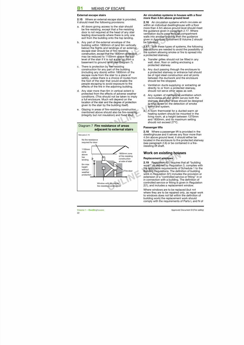
External escape stairs
2.15 Where an external escape stair is provided,it should meet the ollowing provisions:
a. All doors giving access to the stair shouldbe re-resisting, except that a re-resistingdoor is not required at the head o any stairleading downwards where there is only oneexit rom the building onto the top landing.
b. Any part o the external envelope o thebuilding within 800mm o (and 9m verticallybelow) the fights and landings o an externalescape stair should be o re-resistingconstruction, except that the 800mm dimensionmay be reduced to 00mm above the toplevel o the stair i it is not a stair up rom abasement to ground level (see Diagram 7).
c. There is protection by re-resistingconstruction or any part o the building(including any doors) within 800mm o theescape route rom the stair to a place osaety, unless there is a choice o routes romthe oot o the stair that would enable thepeople escaping to avoid exposure to theeects o the re in the adjoining building.
d. Any stair more than 6m in vertical extent isprotected rom the eects o adverse weatherconditions. (This should not be taken to implya ull enclosure. Much will depend on thelocation o the stair and the degree o protectiongiven to the stair by the building itsel).
e. Glazing in areas o re-resisting constructionmentioned above should also be re-resisting(integrity but not insulation) and xed shut.
Air circulation systems in more than 4.5m above gro
2.16 Air circulation systemwithin an individual dwelling
more than 4.5m above grouthe guidance given in paragventilation ducts pass throuwalls into another building tgiven in Approved Documenbe ollowed.
2.17 With these types o sprecautions are needed to athe system allowing smoke
a protected stairway:a. Transer grilles should n
wall, door, foor or ceilinprotected stairway.
b. Any duct passing througa protected stairway or be o rigid steel construbetween the ductwork ashould be re-stopped.
c. Ventilation ducts supplydirectly to or rom a proshould not serve other a
d. Any system o mechanicrecirculates air and whicstairway and other areasto shut down on the detwithin the system.
e. A room thermostat or aheating system should bliving room, at a height band 830mm, and its mshould not exceed 27ºC
Passenger lits
2.18 Where a passenger lidwellinghouse and it serves
4.5m above ground level, it located in the enclosure to t(see paragraph 2.6) or be coresisting lit shat.
Work on existing ho
B1 MEANS OF ESCAPE
No fire resistance
required for door
1100mm
zone
above1800mm zone
Diagram 7 Fire resistance o areasadjacent to external stairs
See para 2.5
MEANS OF ESCAPE
7/29/2019 Bldg_Reg_2006
http://slidepdf.com/reader/full/bldgreg2006 25/86
Schedule . In addition, the building should nothave a lesser level o compliance, ater the workhas been completed, with other applicable Partso Schedule .
For the purposes o Part B, where a window islocated such that, in a new dwellinghouse, anescape window would be necessary and thewindow is o sucient size that it could be usedor the purposes o escape then:
a. the replacement window opening should besized to provide at least the same potentialor escape as the window it replaces; or
b. where the original window is larger thannecessary or the purposes o escape, thewindow opening could be reduced down tothe minimum specied in paragraph 2.8.
Note: Part B3 makes provisions or cavitybarriers around window openings in some ormso construction. Where windows are replaced itmay be necessary to consider i adequateprotection is maintained.
Material alterations
2.20 Paragraph 0.20 sets out the requirementsrelating to material alterations. What constitutesreasonable provision where undertaking materialalterations would depend on the circumstances inthe particular case and would need to take accounto historic value (see paragraph 0.29). Possibleways o satisying the requirements include:
a. Smoke alarmsWhere new habitable rooms are provided thensmoke alarms should be provided in accordancewith paragraph .8.
b. Lot conversions
Where a new storey is to be added by convertingan existing roo space, the provisions or escapeneed to be considered throughout the ull
extent o the escape route. For example, a lotconversion to a two-storey house will result inthe need to protect the stairway (by providingre-resisting doors and partitions) wherepreviously no protection may have existed(see paragraph 2.6a).
Note: I it is considered undesirable to replace
Alternatively, it may sprinkler protection tconjunction with a door (E20), in order trom the upper storearranged to allow thto access an escape(in accordance with o a re in the open-should be separatedwith re-resisting co
MEANS OF ESCAPE
B2 INTERNAL FIRE SPREAD (LININGS)
7/29/2019 Bldg_Reg_2006
http://slidepdf.com/reader/full/bldgreg2006 26/86
This Approved Document deals with theollowing Requirement rom Part B o Schedule
to the Building Regulations 2000 (as amended).
Requirement Limitsonapplication
Internal fire spread (linings)
B2. (1) To inhibit the spread of fire within the building, the
internal linings shall:
(a) adequately resist the spread of flame over their
surfaces; and
(b) have, if ignited, a rate of heat release or a rate of
fire growth, which is reasonable in the circumstances.
(2) In this paragraph ‘internal linings’ mean the materials
or products used in lining any partition, wall, ceiling or
other internal structure.
The RequirementB2 INTERNAL FIRE SPREAD (LININGS)
7/29/2019 Bldg_Reg_2006
http://slidepdf.com/reader/full/bldgreg2006 27/86
Perormance
In the Secretary o State’s view the Requirementso B2 will be met i the spread o fame over theinternal linings o the building is restricted bymaking provision or them to have low rates osurace spread o fame and, in some cases, tohave a low rate o heat release, so as to limit thecontribution that the abric o the building makesto re growth. In relation to the European retests and classication system, the requirementso B2 will be met i the heat released rom the
internal linings is restricted by making provisionor them to have a resistance to ignition and arate o re growth which are reasonable in thecircumstances.
The extent to which this is necessary isdependent on the location o the lining.
Introduction
Fire spread and internal linings
B2.i The choice o materials or walls andceilings can signicantly aect the spread o are and its rate o growth, even though they arenot likely to be the materials rst ignited.
It is particularly important in circulation spaceswhere linings may oer the main means by whichre spreads and where rapid spread is most likely
to prevent occupants rom escaping.Several properties o lining materials infuencere spread. These include the ease o ignitionand the rate at which the lining material gives oheat when burning. The guidance relating to theEuropean re tests and classication provides orcontrol o internal re spread through control othese properties. This document does not givedetailed guidance on other properties, such as
the generation o smoke and umes.
Floors and stairs
B2.ii The provisions do not apply to the uppersuraces o foors and stairs because they arenot signicantly involved in a re until it is welldeveloped and thus do not play an important
Classiication o pe
B2.v Appendix A do perormance and test (see paragraphs
The national classictests in BS 476 Fire and structures, nameo test or re propagBS 476-7:997 Meththe classication o to products. Howevecombustibility test o:982 Method or rom building producmethod o meeting Cavailable or classicmaterials i they do nrating under BS 476reerred to as TP(a) rTP(b), are used.
The European classiBS EN 350-:2002construction producPart Classication re tests. They are bour European test m
• BS EN ISO 82or building produ
• BS EN ISO 76or building prod gross caloric va
• BS EN 3823:20or building prodexcluding fooring attack by a single
• BS EN ISO 92tests or buildingwhen subjected to
For some building prgenerally accepted gprocedure or testingaccordance with thetests. Until such a tim
Guidance
B2
7/29/2019 Bldg_Reg_2006
http://slidepdf.com/reader/full/bldgreg2006 28/86
Classication o linings
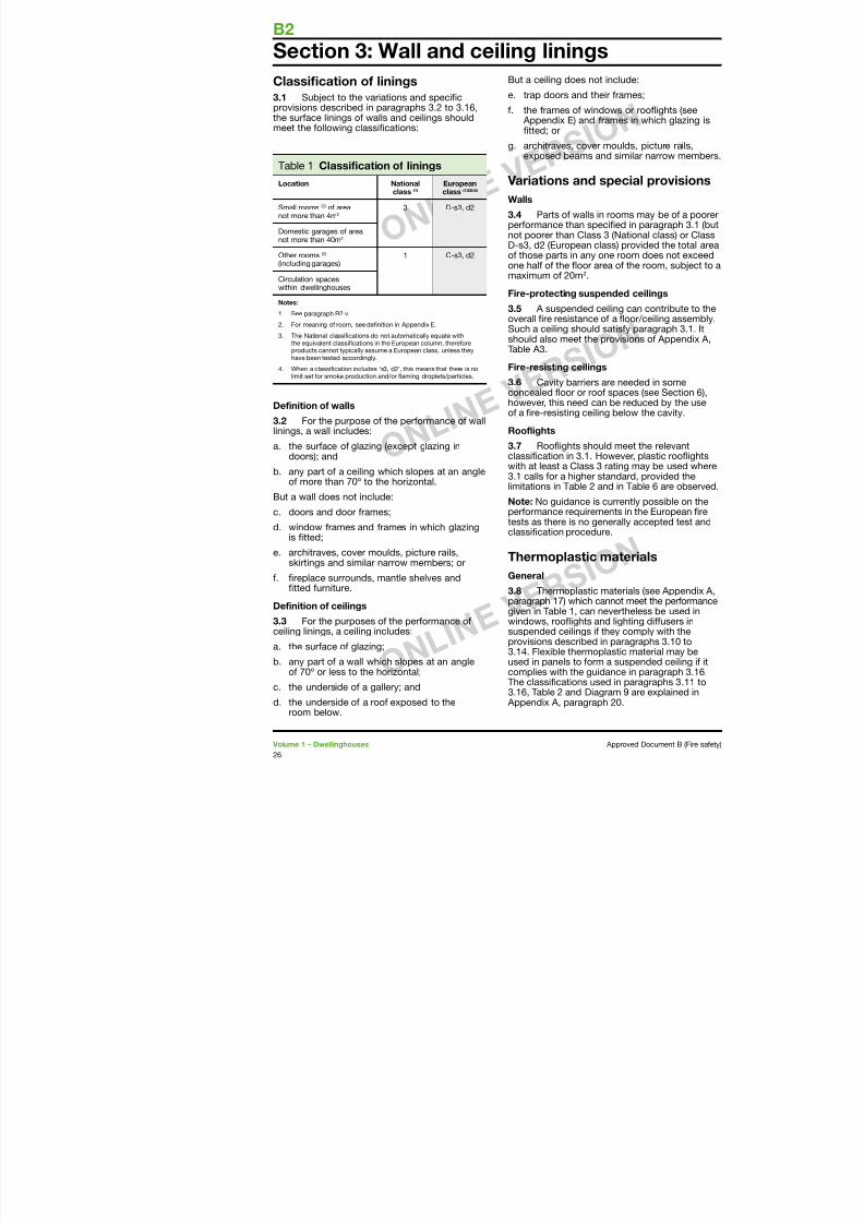
3.1 Subject to the variations and specicprovisions described in paragraphs 3.2 to 3.6,the surace linings o walls and ceilings shouldmeet the ollowing classications:
Table Classiication o linings
Location Nationalclass (1)
Europeanclass (1)(3)(4)
Small rooms (2) o areanot more than 4m2
3 D-s3, d2
Domestic garages o areanot more than 40m2
Other rooms (2) (including garages)
C-s3, d2
Circulation spaceswithin dwellinghouses
Notes:
. See paragraph B2.v.
2. For meaning o room, see deinition in Appendix E.
3. The National classiications do not automatically equate withthe equivalent classiications in the European column, thereoreproducts cannot typically assume a European class, unless theyhave been tested accordingly.
4. When a classiication includes ‘s3, d2’, this means that there is nolimit set or smoke production and/or laming droplets/particles.
Deinition o walls
3.2 For the purpose o the perormance o walllinings, a wall includes:
a. the surace o glazing (except glazing indoors); and
b. any part o a ceiling which slopes at an angleo more than 70º to the horizontal.
But a wall does not include:
c. doors and door rames;
d. window rames and rames in which glazingis tted;
But a ceiling does not includ
e. trap doors and their ram
. the rames o windows o Appendix E) and ramestted; or
g. architraves, cover mouldexposed beams and sim
Variations and spec
Walls
3.4 Parts o walls in roomperormance than speciednot poorer than Class 3 (NaD-s3, d2 (European class) po those parts in any one roone hal o the foor area o maximum o 20m2.
Fire-protecting suspended3.5 A suspended ceiling overall re resistance o a foSuch a ceiling should satisyshould also meet the provisTable A3.
Fire-resisting ceilings
3.6 Cavity barriers are ne
concealed foor or roo spachowever, this need can be ro a re-resisting ceiling belo
Roolights
3.7 Roofights should meclassication in 3.. Howevewith at least a Class 3 rating3. calls or a higher standa
limitations in Table 2 and in Note: No guidance is currenperormance requirements itests as there is no generallclassication procedure.
Section 3: Wall and ceiling linings
WALL AND CEILING LININGS
7/29/2019 Bldg_Reg_2006
http://slidepdf.com/reader/full/bldgreg2006 29/86
Note: No guidance is currently possible on theperormance requirements in the European retests as there is no generally accepted test andclassication procedure.
Windows and internal glazing3.9 External windows to rooms (thoughnot to circulation spaces) may be glazed withthermoplastic materials, i the material can beclassied as a TP(a) rigid product.
Internal glazing should meet the provisions inparagraph 3..
Notes:
. A ‘wall’ does not include glazing in a door(see paragraph 3.2).
2. Attention is drawn to the guidance onthe saety o glazing in Approved Document NGlazing – saety in relation to impact, opening and cleaning.
Roolights
3.10 Roofights to rooms and circulation spaces(with the exception o protected stairways) maybe constructed o a thermoplastic material i:
a. the lower surace has a TP(a) (rigid) or TP(b)classication
b. the size and disposition o the roofightsaccords with the limits in Table 2 and withthe guidance to B4 in Table 7.
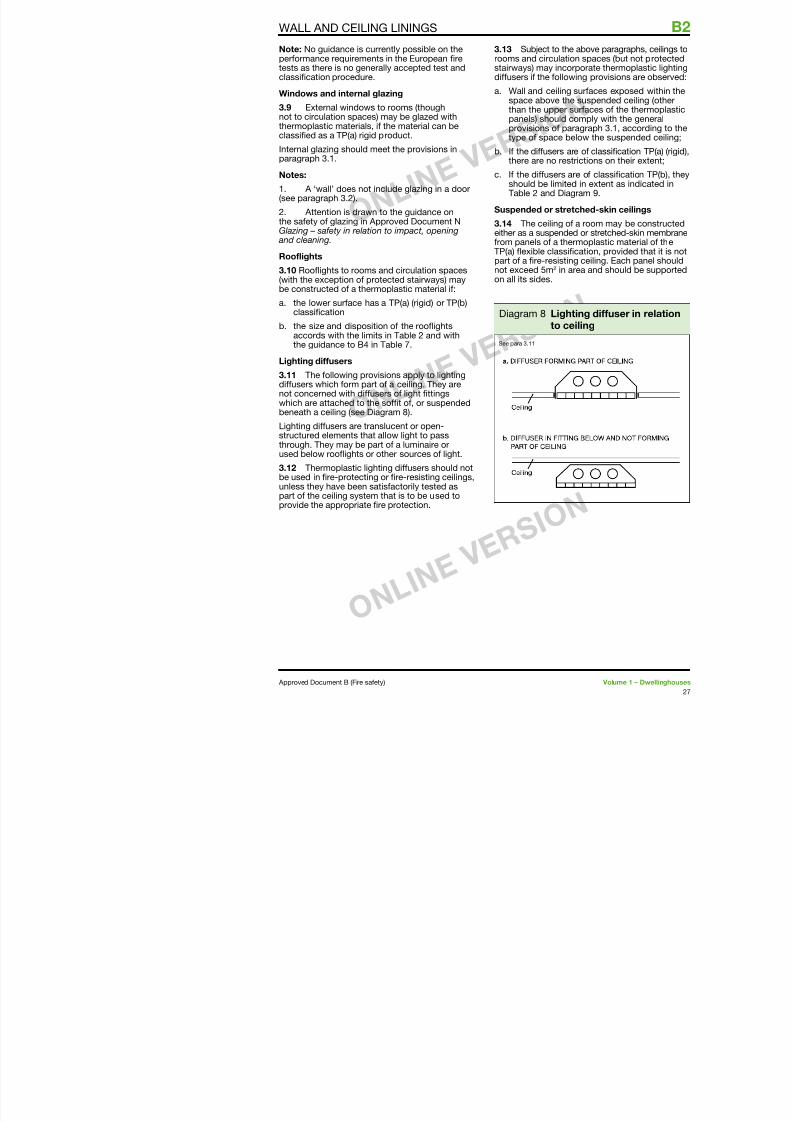
Lighting diusers
3.11 The ollowing provisions apply to lightingdiusers which orm part o a ceiling. They arenot concerned with diusers o light ttingswhich are attached to the sot o, or suspendedbeneath a ceiling (see Diagram 8).
Lighting diusers are translucent or open-structured elements that allow light to pass
through. They may be part o a luminaire orused below roofights or other sources o light.
3.12 Thermoplastic lighting diusers should notbe used in re-protecting or re-resisting ceilings,unless they have been satisactorily tested aspart o the ceiling system that is to be used to
id th i t t ti
3.13 Subject to the rooms and circulatiostairways) may incordiusers i the ollow
a. Wall and ceiling sspace above thethan the upper spanels) should coprovisions o partype o space be
b. I the diusers arthere are no rest
c. I the diusers ar
should be limitedTable 2 and Diag
Suspended or stret
3.14 The ceiling o either as a suspendedrom panels o a therTP(a) fexible classipart o a re-resisting
not exceed 5m2 in aron all its sides.
Diagram 8 Lightto ce
See para 3.
B2 WALL AND CEILING LININGS
7/29/2019 Bldg_Reg_2006
http://slidepdf.com/reader/full/bldgreg2006 30/86
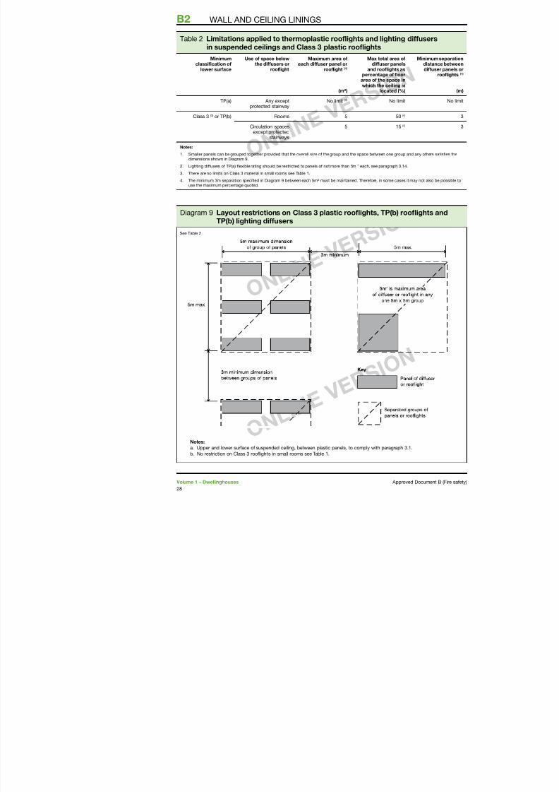
Table 2 Limitations applied to thermoplastic roolights and lightingin suspended ceilings and Class 3 plastic roolights
Minimumclassiication o
lower surace
Use o space belowthe diusers or
roolight
Maximum area oeach diuser panel or
roolight (1)
(m²)
Max total area odiuser panels
and roolights aspercentage o loorarea o the space inwhich the ceiling is
located (%)
TP(a) Any exceptprotected stairway
No limit (2) No limit
Class 3 (3) or TP(b) Rooms 5 50 (4)
Circulation spacesexcept protectedstairways
5 5
(4)
Notes:
. Smaller panels can be grouped together provided that the overall size o the group and the space between one groudimensions shown in Diagram 9.
2. Lighting diusers o TP(a) lexible rating should be restricted to panels o not more than 5m2 each, see paragraph 3.
3. There are no limits on Class 3 material in small rooms see Table .
4. The minimum 3m separation speciied in Diagram 9 between each 5m² must be maintained. Thereore, in some caseuse the maximum percentage quoted.
Diagram 9 Layout restrictions on Class 3 plastic roofights, TP(b) roTP(b) lighting diusers
See Table 2
INTERNAL FIRE SPREAD (STRUCTURE)
7/29/2019 Bldg_Reg_2006
http://slidepdf.com/reader/full/bldgreg2006 31/86
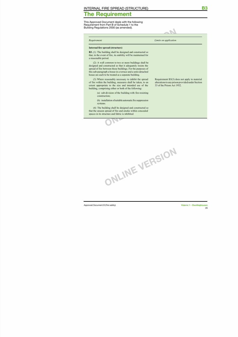
This Approved Document deals with the ollowingRequirement rom Part B o Schedule to the
Building Regulations 2000 (as amended).
Requirement Limitsonapplicat
Internal fire spread (structure)
B3. (1) The building shall be designed and constructed so
that, in the event of fire, its stability will be maintained for a reasonable period.
(2) A wall common to two or more buildings shall be
designed and constructed so that it adequately resists the
spread of fire between those buildings. For the purposes of
this sub-paragraph a house in a terrace and a semi-detached
house are each to be treated as a separate building.
(3) Where reasonably necessary to inhibit the spread
of fire within the building, measures shall be taken, to an
extent appropriate to the size and intended use of the
building, comprising either or both of the following:
(a) sub-division of the building with fire-resisting
construction;
(b) installation of suitable automatic fire suppression
systems.
(4) The building shall be designed and constructed sothat the unseen spread of fire and smoke within concealed
spaces in its structure and fabric is inhibited.
Requirement B3(
alterations to any p
33 of the Prison A
The Requirement
B3
7/29/2019 Bldg_Reg_2006
http://slidepdf.com/reader/full/bldgreg2006 32/86
Perormance
In the Secretary o State’s view the Requirementso B3 will be met:
a. i the loadbearing elements o structure othe building are capable o withstanding theeects o re or an appropriate periodwithout loss o stability;
b. i the building is sub-divided by elements ore-resisting construction into compartments;
c. i any openings in re-separating elements(see Appendix E) are suitably protected inorder to maintain the integrity o the element(i.e. the continuity o the re separation); and
d. i any hidden voids in the construction aresealed and sub-divided to inhibit the unseenspread o re and products o combustion, inorder to reduce the risk o structural ailureand the spread o re, in so ar as they posea threat to the saety o people in and aroundthe building.
The extent to which any o these measuresare necessary is dependent on the use o thebuilding and, in some cases, its size, and on thelocation o the element o construction.
Introduction
B3.i Guidance on loadbearing elements ostructure is given in Section 4. Section 5 isconcerned with the sub-division o a buildinginto compartments, and Section 6 makesprovisions about concealed spaces (or cavities).Section 7 gives inormation on the protection oopenings and on re-stopping which relates tocompartmentation and to re spread in concealedspaces. Common to all these sections and toother provisions o Part B, is the property o
re resistance.
Fire resistance
B3.ii The re resistance o an element oconstruction is a measure o its ability towithstand the eects o re in one or more ways,
ll
unction o a foor, are not trstructure. External walls, su
other orms o cladding whiweight and wind loads and load, are not regarded as lopurposes o B3.ii(a), althougre resistance to satisy reqSections 8 to 9).
Loadbearing elements may re-separating unction. Simelements may or may not b
Guidance elsewhere in theDocument concerning ire
B3.iv There is guidance in the use o re-resisting consmeans o escape. There is gabout re resistance o extethe spread o re between bgives inormation on methodperormance or elements o Appendix B gives inormatio Appendix C gives inormatiomeasurement. Appendix D gon purpose group classicagives denitions.
Guidance
S
7/29/2019 Bldg_Reg_2006
http://slidepdf.com/reader/full/bldgreg2006 33/86
Introduction4.1 Premature ailure o the structure can beprevented by provisions or loadbearing elementso structure to have a minimum standard o reresistance, in terms o resistance to collapse orailure o loadbearing capacity. The purpose inproviding the structure with re resistance isthreeold, namely:
a. to minimise the risk to the occupants, someo whom may be unable to make their ownescape i they have become trapped or injured;
b. to reduce the risk to reghters, who may beengaged in search or rescue operations; and
c. to reduce the danger to people in the vicinityo the building, who might be hurt by allingdebris or as a result o the impact o thecollapsing structure on other buildings.
Fire resistance standard
4.2 Elements o structure such as structuralrames, beams, columns, loadbearing walls(internal and external), foor structures and gallerystructures should have at least the re resistancegiven in Appendix A, Table A.
Application o the ire resistance standards orloadbearing elements
4.3 The measures set out in Appendix A include provisions to ensure that where oneelement o structure supports or gives stabilityto another element o structure, the supportingelement has no less re resistance than the otherelement (see notes to Table A2). The measuresalso provide or elements o structure that arecommon to more than one building orcompartment, to be constructed to the standardo the greater o the relevant provisions. Specialprovisions about re resistance o elements ostructure in single storey buildings are also givenand there are concessions in respect o reresistance o elements o structure in basements
b. the lowest foor o
Additional guidance
4.5 Guidance in o Approved Documentloadbearing wall is:
a. a compartment wcommon to two
b. a wall between aintegral garage, (s
c. protecting a mea(see Section 2); o
d. an external wall,
4.6 I a foor is alssee Section 5.
Floors in lot conve
4.7 In altering an eamily dwellinghousethe provisions in thisor the foor(s), both 30 minute standard o Appendix A, Table Athe ollowing conditio
a. only one storey i
b. the new storey chabitable rooms;
c. the total area o amount to more
then the existing rsaccepted i it has at standard o re resiswhere the foor sepa
circulation spaces).Notes:
. The ‘modiedsatises the test critin respect o loadbeareduced perormanc
Section 4: Loadbearing elementso structure
S ti 5 C t t tiB3
7/29/2019 Bldg_Reg_2006
http://slidepdf.com/reader/full/bldgreg2006 34/86
Introduction
5.1 The spread o re within a building can berestricted by sub-dividing it into compartmentsseparated rom one another by walls and/orfoors o re-resisting construction. The objectis twoold:
a. to prevent rapid re spread which could trapoccupants o the building; and
b. to reduce the chance o res becominglarge, on the basis that large res are more
dangerous, not only to occupants and reand rescue service personnel, but also topeople in the vicinity o the building.Compartmentation is complementary toprovisions made in Section 2 or the protectiono escape routes, and to provisions made inSections 8 to 0 against the spread o rebetween buildings.
Provision o compartmentation5.2 Compartment walls and compartmentfoors should be provided in the circumstancesdescribed below, with the proviso that thelowest foor in a building does not need to beconstructed as a compartment foor. Provisionsor the protection o openings in compartmentwalls and compartment foors are given inparagraph 5.3 and Section 7.
5.3 Every wall separating semi-detachedhouses, or houses in terraces, should beconstructed as a compartment wall and thehouses should be considered as separatebuildings.
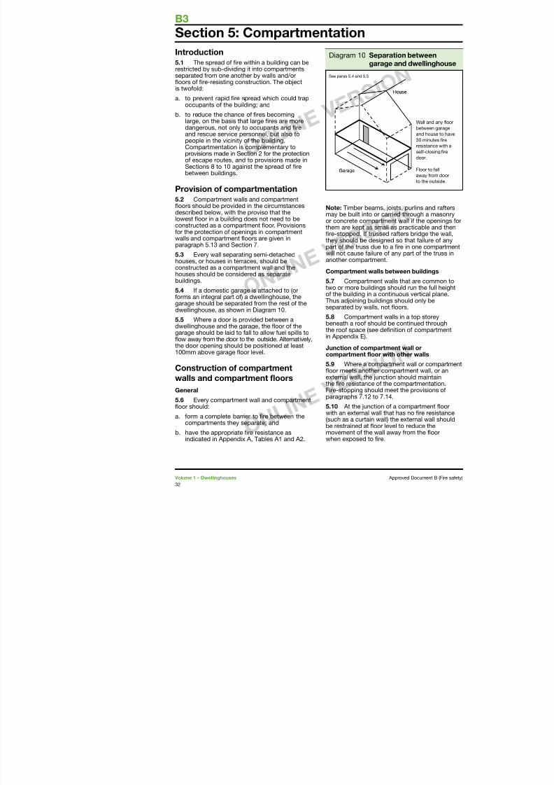
5.4 I a domestic garage is attached to (ororms an integral part o) a dwellinghouse, thegarage should be separated rom the rest o thedwellinghouse, as shown in Diagram 0.
5.5 Where a door is provided between adwellinghouse and the garage, the foor o thegarage should be laid to all to allow uel spills tofow away rom the door to the outside. Alternatively,the door opening should be positioned at least00mm above garage foor level
Note: Timber beams, joistsmay be built into or carried or concrete compartment wthem are kept as small as pre-stopped. I trussed ratethey should be designed sopart o the truss due to a re
will not cause ailure o any another compartment.
Compartment walls betwe
5.7 Compartment walls ttwo or more buildings shoulo the building in a continuoThus adjoining buildings shoseparated by walls, not foo
5.8 Compartment walls ibeneath a roo should be cothe roo space (see denitioin Appendix E).
Junction o compartment
Section 5: Compartmentation
Diagram 0 Separatio
garage anSee paras 5.4 and 5.5
COMPARTMENTATION
7/29/2019 Bldg_Reg_2006
http://slidepdf.com/reader/full/bldgreg2006 35/86
Junction o compartment wall with roo
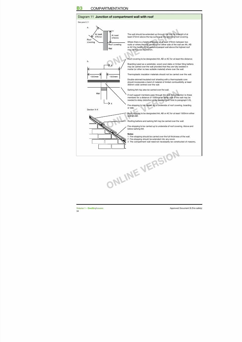
5.11 A compartment wall should be taken up tomeet the underside o the roo covering or deck,with re-stopping where necessary at the wall/
roo junction to maintain the continuity o reresistance. The compartment wall should alsobe continued across any eaves.
5.12 I a re penetrates a roo near a compartmentwall there is a risk that it will spread over the rooto the adjoining compartment. To reduce thisrisk either:
a. the wall should be extended up through theroo or a height o at least 375mm above the
top surace o the adjoining roo covering(see Diagram a). Where there is a heightdierence o at least 375mm between tworoos or where the roo coverings on eitherside o the wall are AA, AB or AC this heightmay be reduced to 200mm; or
b. a zone o the roo 500mm wide on eitherside o the wall should have a covering odesignation AA, AB or AC. Any combustible
boarding used as a substrate to the roocovering, wood wool slabs, or timber tilingbattens that are carried over the compartmentwall should be ully bedded in mortar or othersuitable material over the width o the wall(see Diagram b).
Note: Double-skinned insulated roo sheetingwith a thermoplastic core should incorporate aband o material o limited combustibility at least
300mm wide centred over the wall.
Openings in co
Openings in compabuildings or occupa
5.13 Any openingsis common to two orlimited to those or:
a. a door which is no escape in cassame re resistathe wall (see Apptted in accordan Appendix B; and
b. the passage o aprovisions in Sec
Doors
5.14 Inormation on Appendix B.
B3 COMPARTMENTATION
7/29/2019 Bldg_Reg_2006
http://slidepdf.com/reader/full/bldgreg2006 36/86
X
X
The wall should be extended up through the roof for
least 375mm above the top surface of the adjoining
Where there is a height difference of at least 375mm
roofs or where the roof coverings on either side of th
or AC the height of the upstand/parapet wall above t
may be reduced to 200mm.
Roof covering to be designated AA, AB or AC for at
Boarding (used as a substrate), wood wool slabs or t
may be carried over the wall provided that they are fu
mortar (or other no less suitable material) where over
Thermoplastic insulation materials should not be car
Double-skinned insulated roof sheeting with a therm
should incorporate a band of material of limited com300mm wide centred over the wall.
Sarking felt may also be carried over the wall.
If roof support members pass through the wall, fire p
members for a distance of 1500mm on either side of
needed to delay distortion at the junction (see note t
Fire-stopping to be carried up to underside of roof c
or slab.
a.
b.
Section X–X
Roof covering to be designated AA, AB or AC for at
side of wall.
Roofing battens and sarking felt may be carried over
Fire-stopping to be carried up to underside of roof co
below sarking felt.
Notes
1 Fire-stopping should be carried over the full thickn2 Fire-stopping should be extended into any eaves.
3 The compartment wall need not necessarily be co
Diagram Junction o compartment wall with roo
See para 5.
Section 6: Concealed spaces (ca
7/29/2019 Bldg_Reg_2006
http://slidepdf.com/reader/full/bldgreg2006 37/86
Introduction
6.1 Concealed spaces or cavities in theconstruction o a building provide a ready routeor smoke and fame spread e.g. in walls, foors,ceilings and roos. As any spread is concealed,it presents a greater danger than would a moreobvious weakness in the abric o the building.
Provision o cavity barriers
6.2 Provisions are given below or cavity
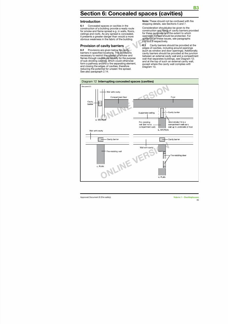
barriers in specied locations. The provisionsnecessary to restrict the spread o smoke andfames through cavities are broadly or the purposeo sub-dividing cavities, which could otherwiseorm a pathway around a re separating element,and closing the edges o cavities; thereorereducing the potential or unseen re spread.See also paragraph 2.4.
Note: These should stopping details, see
Consideration shouldconstruction and xior these purposes aopenings in them shguidance on these is6.6 to 6.9 respective
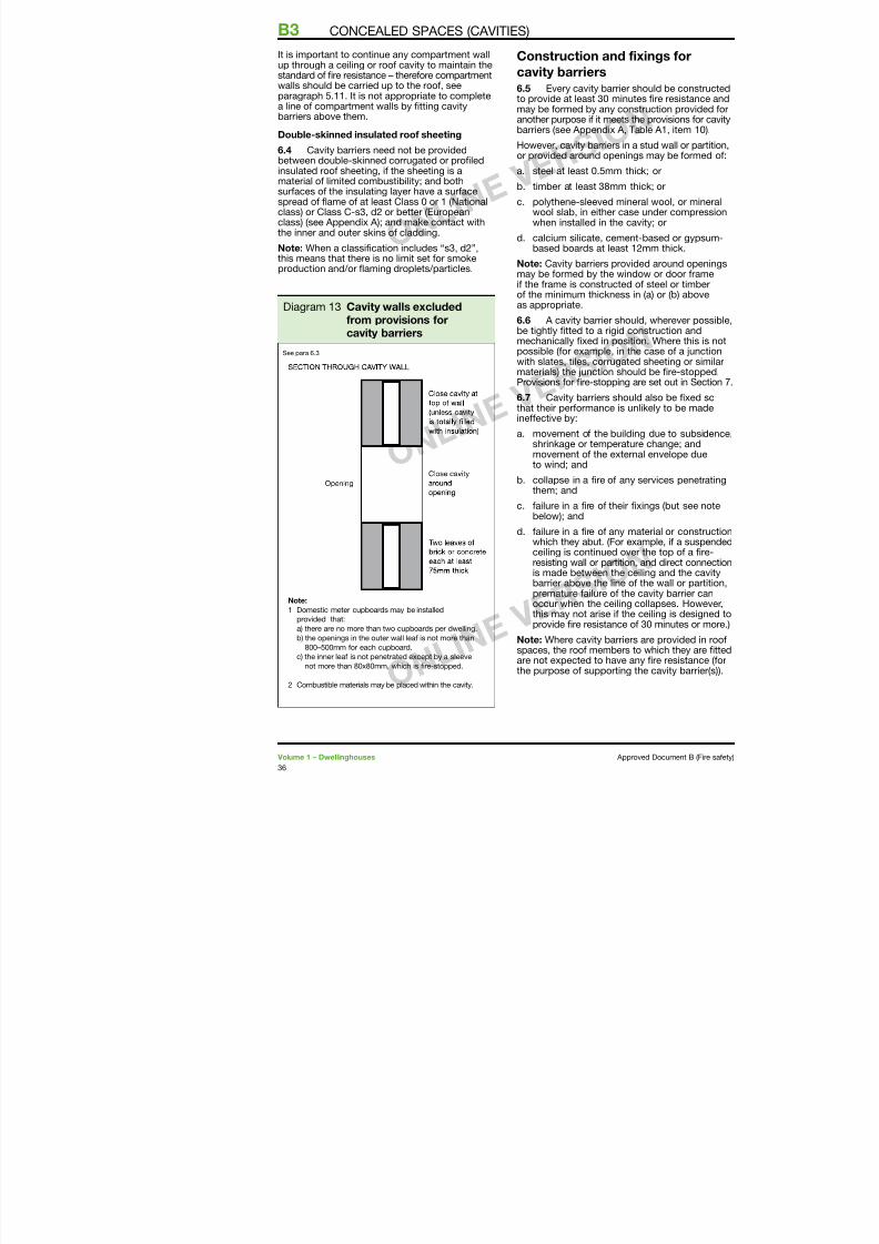
6.3 Cavity barriersedges o cavities, inc(such as window and
cavity barriers shoulbetween an external cwall that separates band at the top o sucexcept where the caDiagram 3.
Section 6: Concealed spaces (ca
Diagram 2 Interrupting concealed spaces (cavities)
See para 6.3
B3 CONCEALED SPACES (CAVITIES)
7/29/2019 Bldg_Reg_2006
http://slidepdf.com/reader/full/bldgreg2006 38/86
It is important to continue any compartment wallup through a ceiling or roo cavity to maintain thestandard o re resistance – thereore compartmentwalls should be carried up to the roo, seeparagraph 5.. It is not appropriate to complete
a line o compartment walls by tting cavitybarriers above them.
Double-skinned insulated roo sheeting
6.4 Cavity barriers need not be providedbetween double-skinned corrugated or proledinsulated roo sheeting, i the sheeting is amaterial o limited combustibility; and bothsuraces o the insulating layer have a surace
spread o fame o at least Class 0 or (Nationalclass) or Class C-s3, d2 or better (Europeanclass) (see Appendix A); and make contact withthe inner and outer skins o cladding.
Note: When a classication includes “s3, d2”,this means that there is no limit set or smokeproduction and/or faming droplets/particles.
Construction and ix
cavity barriers
6.5 Every cavity barrier sto provide at least 30 minute
may be ormed by any consanother purpose i it meets thbarriers (see Appendix A, Ta
However, cavity barriers in aor provided around opening
a. steel at least 0.5mm thic
b. timber at least 38mm th
c. polythene-sleeved minewool slab, in either casewhen installed in the cav
d. calcium silicate, cementbased boards at least 2
Note: Cavity barriers providmay be ormed by the windi the rame is constructed oo the minimum thickness in
as appropriate.
6.6 A cavity barrier shoube tightly tted to a rigid comechanically xed in positiopossible (or example, in thewith slates, tiles, corrugatedmaterials) the junction shouProvisions or re-stopping a
6.7 Cavity barriers shouldthat their perormance is unineective by:
a. movement o the buildinshrinkage or temperaturmovement o the externto wind; and
b. collapse in a re o any them; and
c. ailure in a re o their xbelow); and
d. ailure in a re o any mawhich they abut. (For exaceiling is continued over
Diagram 3 Cavity walls excludedrom provisions orcavity barriers
See para 6.3
O i i it b i
CONCEALED SPACES (CAVITIES)
7/29/2019 Bldg_Reg_2006
http://slidepdf.com/reader/full/bldgreg2006 39/86
Openings in cavity barriers
6.8 Any openings in a cavity barrier should belimited to those or:
a. doors which have at least 30 minutes re
resistance (see Appendix B, Table B, item(a)) and are tted in accordance with theprovisions o Appendix B;
b. the passage o pipes which meet theprovisions in Section 7;
c. the passage o cables or conduits containingone or more cables;
d. openings tted with a suitably mounted
automatic re damper; and
e. ducts which are re-resisting or are tted witha suitably mounted automatic re damperwhere they pass through the cavity barrier.
Section 7: Protection o openingsB3
7/29/2019 Bldg_Reg_2006
http://slidepdf.com/reader/full/bldgreg2006 40/86
Introduction7.1 Sections 7 and 8 make provisions orre-separating elements and set out thecircumstances in which there may be openingsin them. This section deals with the protectiono openings in such elements.
7.2 I a re-separating element is to beeective, then every joint, or imperection o t,or opening to allow services to pass through theelement, should be adequately protected bysealing or re-stopping so that the re resistanceo the element is not impaired.
7.3 The measures in this section are intendedto delay the passage o re. They generally havethe additional benet o retarding smoke spreadbut the test specied in Appendix A or integritydoes not directly stipulate criteria or thepassage o smoke.
7.4 Consideration shouldthe eect o services that mconstruction that could advresistance. For instance, whloudspeakers and other elecinstalled, additional protectito maintain the integrity o a
7.5 Detailed guidance onre doors is given in Appen
Openings or pipes
7.6 Pipes which pass threlements (unless the pipe isshould meet the appropriatealternatives A, B or C below
Alternative A: Proprietary (any pipe diameter)
7.7 Provide a proprietaryhas been shown by test to mresistance o the wall, foor
Alternative B: Pipes with a
7.8 Where a proprietary sused, re-stopping may be keeping the opening as smanominal internal diameter o
not be more than the relevain Table 3.
Section 7: Protection o openingsand ire-stopping
Table 3 Maximum nominal internal diameter o pipes passing throua ire separating element (see paragraph 7.6 to 7.9)
Pipe material and maximum nominal int
Situation (a)
Non-combustiblematerial (1)
(b)
Lead, aluminiumaluminium alloy,uPVC (2), ibrecement
. Wall separating dwellinghouses 60 60 (stack pipe) (3
Alternative C: sleeving
PROTECTION OF OPENINGS AND FIRE-STOPPING
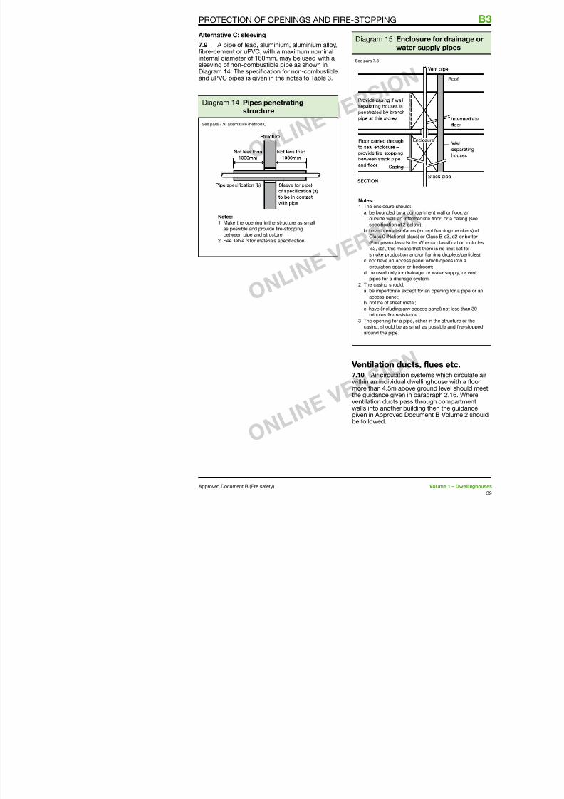
7/29/2019 Bldg_Reg_2006
http://slidepdf.com/reader/full/bldgreg2006 41/86
Alternative C: sleeving
7.9 A pipe o lead, aluminium, aluminium alloy,bre-cement or uPVC, with a maximum nominalinternal diameter o 60mm, may be used with asleeving o non-combustible pipe as shown inDiagram 4. The specication or non-combustibleand uPVC pipes is given in the notes to Table 3.
Diagram 4 Pipes penetratingstructure
Notes:
1 Make the opening in the structure as small
as possible and provide fire-stopping
between pipe and structure.
2 See Table 3 for materials specification.
See para 7.9, alternative method C
Diagram 5 Encwat
Notes:
1 The enclosure should
a. be bounded by a c
outside wall, an int
specification at 2 b
b. have internal surfac
Class 0 (National c
(European class) N
‘s3, d2’, this mean
smoke production
c. not have an access
circulation space o
d. be used only for dr
pipes for a drainag
2 The casing should:
a. be imperforate exc
access panel;
b. not be of sheet me
c. have (including any
minutes fire resista
3 The opening for a pipcasing, should be as
around the pipe.
See para 7.8
B3 PROTECTION OF OPENINGS AND FIRE-STOPPING
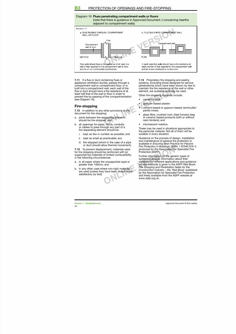
7/29/2019 Bldg_Reg_2006
http://slidepdf.com/reader/full/bldgreg2006 42/86
7.11 I a fue or duct containing fues orappliance ventilation duct(s), passes through acompartment wall or compartment foor, or isbuilt into a compartment wall, each wall o thefue or duct should have a re resistance o atleast hal that o the wall or foor in order toprevent the by-passing o the compartmentation(see Diagram 6).
Fire-stopping7.12 In addition to any other provisions in thisdocument or re-stopping:
a. joints between re-separating elementsshould be re-stopped; and
b. all openings or pipes, ducts, conduitsor cables to pass through any part o are-separating element should be:
i. kept as ew in number as possible; and
ii. kept as small as practicable; and
iii. re-stopped (which in the case o a pipeor duct should allow thermal movement).
7 13 To prevent displacement materials used
7.14 Proprietary re-stoppsystems, (including those dpenetrations) which have bemaintain the re resistance element, are available and m
Other re-stopping material
• cement mortar;
• gypsum-based plaster;
• cement-based or gypsuperlite mixes;
• glass bre, crushed rocor ceramic-based produresin binders); and
• intumescent mastics.
These may be used in situathe particular material. Not
suitable in every situation.Guidance on the process oand maintenance o passiveavailable in Ensuring Best PFire Protection in Buildings (produced by the Associatio
Diagram 6 Flues penetrating compartment walls or foors(note that there is guidance in Approved Document J conceadjacent to compartment walls)
See para 7.
The RequirementEXTERNAL FIRE SPREAD
7/29/2019 Bldg_Reg_2006
http://slidepdf.com/reader/full/bldgreg2006 43/86
This Approved Document deals with theollowing Requirement rom Part B o Schedule to the Building Regulations 2000 (as amended).
Requirement Limitsonapplicat
External fire spread
B4. (1) The external walls of the building shall adequately
resist the spread of f ire over the walls and from one buildingto another, having regard to the height, use and position of
the building.
(2) The roof of the building shall adequately resist the
spread of fire over the roof and from one building to another,
having regard to the use and position of the building.
The Requirement
GuidanceB4
7/29/2019 Bldg_Reg_2006
http://slidepdf.com/reader/full/bldgreg2006 44/86
Perormance
In the Secretary o State’s view the Requirements
o B4 will be met:
a. i the external walls are constructed so thatthe risk o ignition rom an external source,and the spread o re over their suraces, isrestricted by making provision or them tohave low rates o heat release;
b. i the amount o unprotected area in the sideo the building is restricted so as to limit the
amount o thermal radiation that can passthrough the wall, taking the distance betweenthe wall and the boundary into account; and
c. i the roo is constructed so that the risk ospread o fame and/or re penetration roman external re source is restricted.
In each case so as to limit the risk o a respreading rom the building to a building beyondthe boundary, or vice versa.
The extent to which this is necessary is dependenton the use o the building, its distance rom theboundary and, in some cases, its height.
Introduction
External walls
B4.i The construction o external walls and the
separation between buildings to prevent externalre spread are closely related.
The chances o re spreading across an openspace between buildings, and the consequencesi it does, depend on:
a. the size and intensity o the re in thebuilding concerned;
b. the distance between the buildings;
c. the re protection given by their acingsides; and
d. the risk presented to people in the otherbuilding(s).
B4 ii Provisions are made in Section 8 or the
Guidance
Section 8: Construction o extern
7/29/2019 Bldg_Reg_2006
http://slidepdf.com/reader/full/bldgreg2006 45/86
Introduction
8.1 Provisions are made in this section or the
external walls o the building to have sucientre resistance to prevent re spread across therelevant boundary. The provisions are closelylinked with those or space separation in Section 9which sets out limits on the amount o unprotectedarea o wall. As the limits depend on the distanceo the wall rom the relevant boundary, it ispossible or some or all o the walls to have nore resistance, except or any parts which are
loadbearing (see paragraph B3.iii).External walls are elements o structure and therelevant period o re resistance (specied in Appendix A) depends on the use, height and sizeo the building concerned. I the wall is 000mmor more rom the relevant boundary, a reducedstandard o re resistance is accepted in mostcases and the wall only needs re resistancerom the inside.
8.2 Provisions are also made to restrictthe combustibility o external walls o buildingsthat are less than 000mm rom the relevantboundary. This is in order to reduce the surace’ssusceptibility to ignition rom an external source.
In the guidance to Requirement B3, provisionsare made in Section 4 or internal and externalloadbearing walls to maintain their loadbearingunction in the event o re.
Fire resistance standard
8.3 The external walls o the buildingshould have the appropriate re resistancegiven in Appendix A, Table A, unless theyorm an unprotected area under the provisionso Section 9.
External suraces8.4 The external suraces o walls within000mm o the relevant boundary should meetClass 0 (National Class) or Class B-s3,d2 or better(European class). The total amount o combustiblematerial on walls more than 000mm rom the
Section 9: Space separationB4
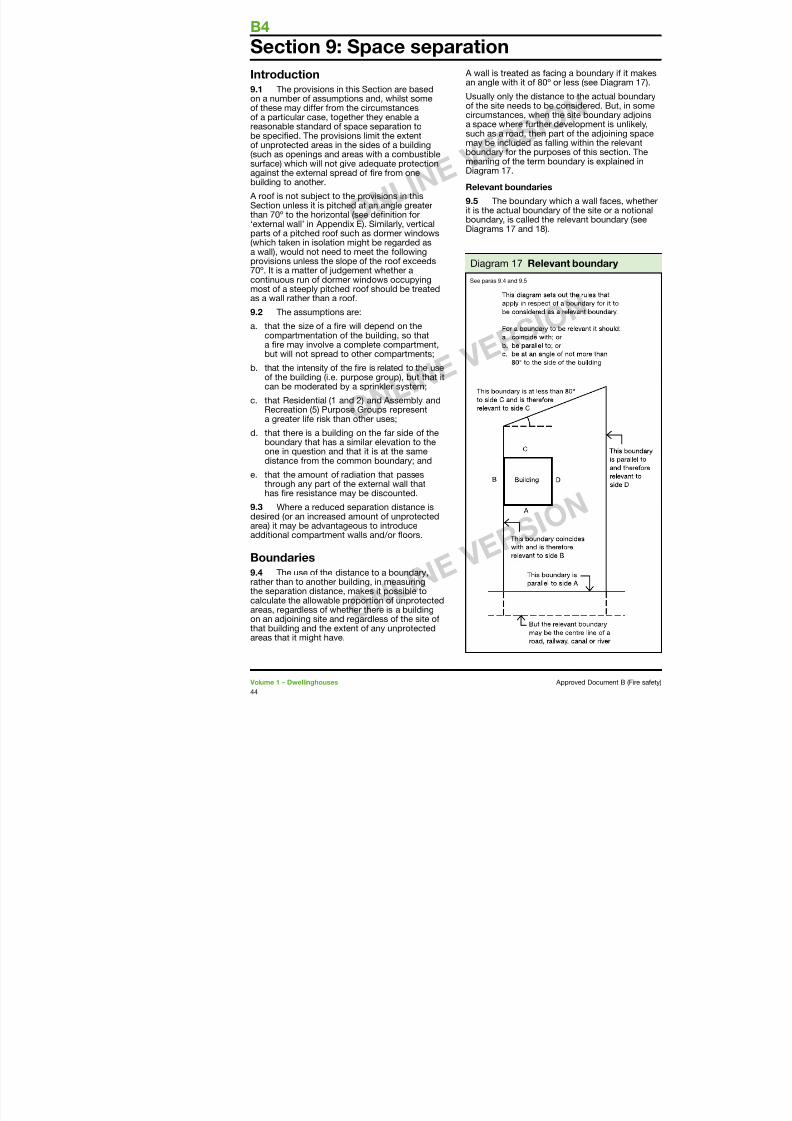
7/29/2019 Bldg_Reg_2006
http://slidepdf.com/reader/full/bldgreg2006 46/86
Introduction
9.1 The provisions in this Section are based
on a number o assumptions and, whilst someo these may dier rom the circumstanceso a particular case, together they enable areasonable standard o space separation tobe specied. The provisions limit the extento unprotected areas in the sides o a building(such as openings and areas with a combustiblesurace) which will not give adequate protectionagainst the external spread o re rom one
building to another. A roo is not subject to the provisions in thisSection unless it is pitched at an angle greaterthan 70º to the horizontal (see denition or‘external wall’ in Appendix E). Similarly, verticalparts o a pitched roo such as dormer windows(which taken in isolation might be regarded asa wall), would not need to meet the ollowingprovisions unless the slope o the roo exceeds
70º. It is a matter o judgement whether acontinuous run o dormer windows occupyingmost o a steeply pitched roo should be treatedas a wall rather than a roo.
9.2 The assumptions are:
a. that the size o a re will depend on thecompartmentation o the building, so thata re may involve a complete compartment,but will not spread to other compartments;
b. that the intensity o the re is related to the useo the building (i.e. purpose group), but that itcan be moderated by a sprinkler system;
c. that Residential ( and 2) and Assembly andRecreation (5) Purpose Groups representa greater lie risk than other uses;
d. that there is a building on the ar side o theboundary that has a similar elevation to the
one in question and that it is at the samedistance rom the common boundary; and
e. that the amount o radiation that passesthrough any part o the external wall thathas re resistance may be discounted.
A wall is treated as acing a an angle with it o 80º or les
Usually only the distance too the site needs to be conscircumstances, when the sita space where urther develsuch as a road, then part omay be included as alling wboundary or the purposes omeaning o the term boundaDiagram 7.
Relevant boundaries
9.5 The boundary which it is the actual boundary o tboundary, is called the relevDiagrams 7 and 8).
p p
Diagram 7 Relevant b
See paras 9.4 and 9.5
Notional boundaries Note: When a classithis means that there
SPACE SEPARATION
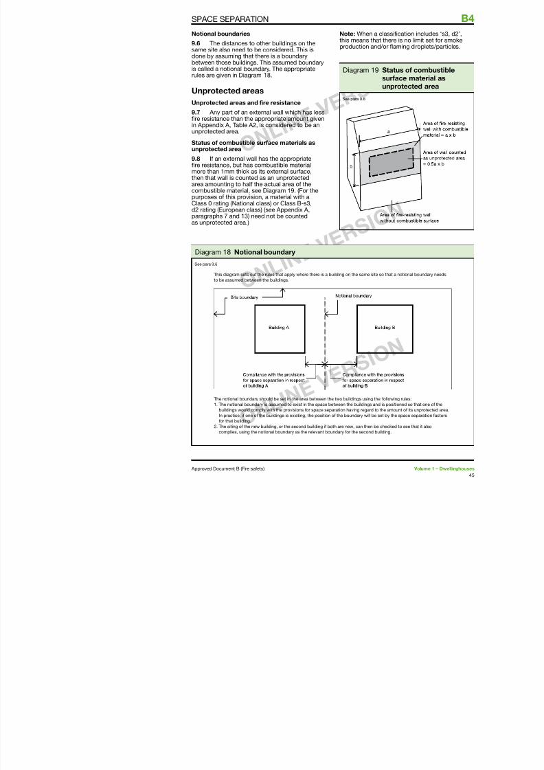
7/29/2019 Bldg_Reg_2006
http://slidepdf.com/reader/full/bldgreg2006 47/86
9.6 The distances to other buildings on thesame site also need to be considered. This isdone by assuming that there is a boundarybetween those buildings. This assumed boundary
is called a notional boundary. The appropriaterules are given in Diagram 8.
Unprotected areas
Unprotected areas and ire resistance
9.7 Any part o an external wall which has lessre resistance than the appropriate amount given
in Appendix A, Table A2, is considered to be anunprotected area.
Status o combustible surace materials asunprotected area
9.8 I an external wall has the appropriatere resistance, but has combustible materialmore than mm thick as its external surace,then that wall is counted as an unprotectedarea amounting to hal the actual area o thecombustible material, see Diagram 9. (For thepurposes o this provision, a material with aClass 0 rating (National class) or Class B-s3,d2 rating (European class) (see Appendix A,paragraphs 7 and 3) need not be counted as unprotected area.)
this means that thereproduction and/or fa
Diagram 9 Statsurunp
See para 9.8
This diagram sets out the rules that apply where there is a building on the same site so that a
to be assumed between the buildings.
Diagram 8 Notional boundary
See para 9.6
Small unprotected areas There are other more precisin a BRE report External re
B4 SPACE SEPARATION
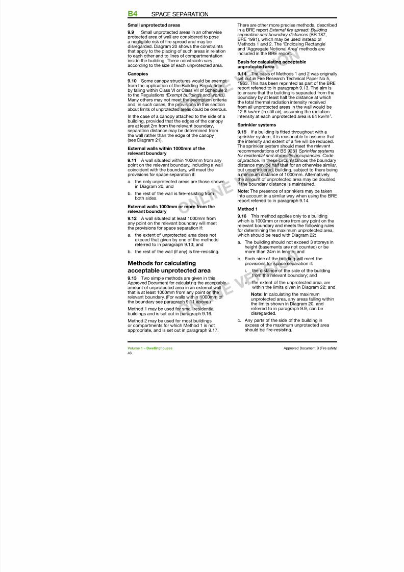
7/29/2019 Bldg_Reg_2006
http://slidepdf.com/reader/full/bldgreg2006 48/86
9.9 Small unprotected areas in an otherwiseprotected area o wall are considered to posea negligible risk o re spread and may bedisregarded. Diagram 20 shows the constraints
that apply to the placing o such areas in relationto each other and to lines o compartmentationinside the building. These constraints varyaccording to the size o each unprotected area.
Canopies
9.10 Some canopy structures would be exemptrom the application o the Building Regulationsby alling within Class VI or Class VII o Schedule 2
to the Regulations (Exempt buildings and works).Many others may not meet the exemption criteriaand, in such cases, the provisions in this sectionabout limits o unprotected areas could be onerous.
In the case o a canopy attached to the side o abuilding, provided that the edges o the canopyare at least 2m rom the relevant boundary,separation distance may be determined romthe wall rather than the edge o the canopy
(see Diagram 2).
External walls within 1000mm o therelevant boundary
9.11 A wall situated within 000mm rom anypoint on the relevant boundary, including a wallcoincident with the boundary, will meet theprovisions or space separation i:
a. the only unprotected areas are those shown
in Diagram 20; and
b. the rest o the wall is re-resisting romboth sides.
External walls 1000mm or more rom therelevant boundary
9.12 A wall situated at least 000mm romany point on the relevant boundary will meet
the provisions or space separation i:a. the extent o unprotected area does not
exceed that given by one o the methodsreerred to in paragraph 9.3; and
b. the rest o the wall (i any) is re-resisting.
in a BRE report External re separation and boundary disBRE 99), which may be uMethods and 2. The ‘Encl
and ‘Aggregate Notional Areincluded in the BRE report.
Basis or calculating acceunprotected area
9.14 The basis o Methodsset out in Fire Research Tec963. This has been reprintereport reerred to in paragra
to ensure that the building isboundary by at least hal thethe total thermal radiation inrom all unprotected areas i2.6 kw/m2 (in still air), assuintensity at each unprotecte
Sprinkler systems
9.15 I a building is tted tsprinkler system, it is reasonthe intensity and extent o aThe sprinkler system shouldrecommendations o BS 925or residential and domestico practice. In these circumsdistance may be hal that obut unsprinklered, building, a minimum distance o 000the amount o unprotected a
i the boundary distance is mNote: The presence o sprininto account in a similar wayreport reerred to in paragra
Method 1
9.16 This method applies which is 000mm or more rrelevant boundary and meet
or determining the maximuwhich should be read with D
a. The building should not height (basements are nmore than 24m in length
Diagram 20 Unprotected areas which may be disregarded in
SPACE SEPARATION
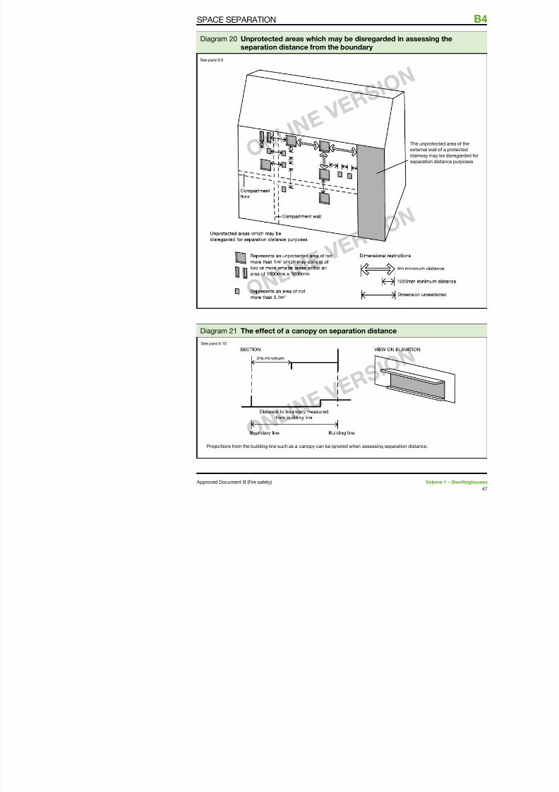
7/29/2019 Bldg_Reg_2006
http://slidepdf.com/reader/full/bldgreg2006 49/86
g p y gseparation distance rom the boundary
See para 9.9
Diagram 2 The eect o a canopy on separation distance
See para 9.0
Table 4 Permitted unpDiagram 22 Permitted unprotected
B4 SPACE SEPARATION
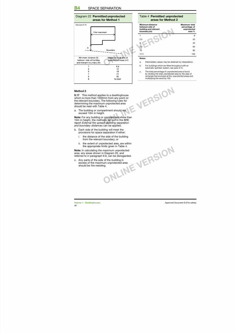
7/29/2019 Bldg_Reg_2006
http://slidepdf.com/reader/full/bldgreg2006 50/86
Method 2
9.17 This method applies to a dwellinghousewhich is more than 000mm rom any point onthe relevant boundary. The ollowing rules ordetermining the maximum unprotected areashould be read with Table 4.
a. The building or compartment should notexceed 0m in height.
Note: For any building or compartment more than0m in height, the methods set out in the BREreport External re spread: Building separation and boundary distances can be applied.
b. Each side o the building will meet theprovisions or space separation i either:
i. the distance o the side o the buildingrom the relevant boundary; or
ii. the extent o unprotected area, are withinthe appropriate limits given in Table 4.
areas or Meth
Minimum distancebetween side o
building and relevantboundary (m)
2.5
5
7.5
0
2.5
Notes:
a. Intermediate values may be
b. For buildings which are ittedautomatic sprinkler system,
c. The total percentage o unprby dividing the total unprotecrectangle that encloses all thmultiplying the result by 00
areas or Method 1
See para 9.6
Section 10: Roo coverings
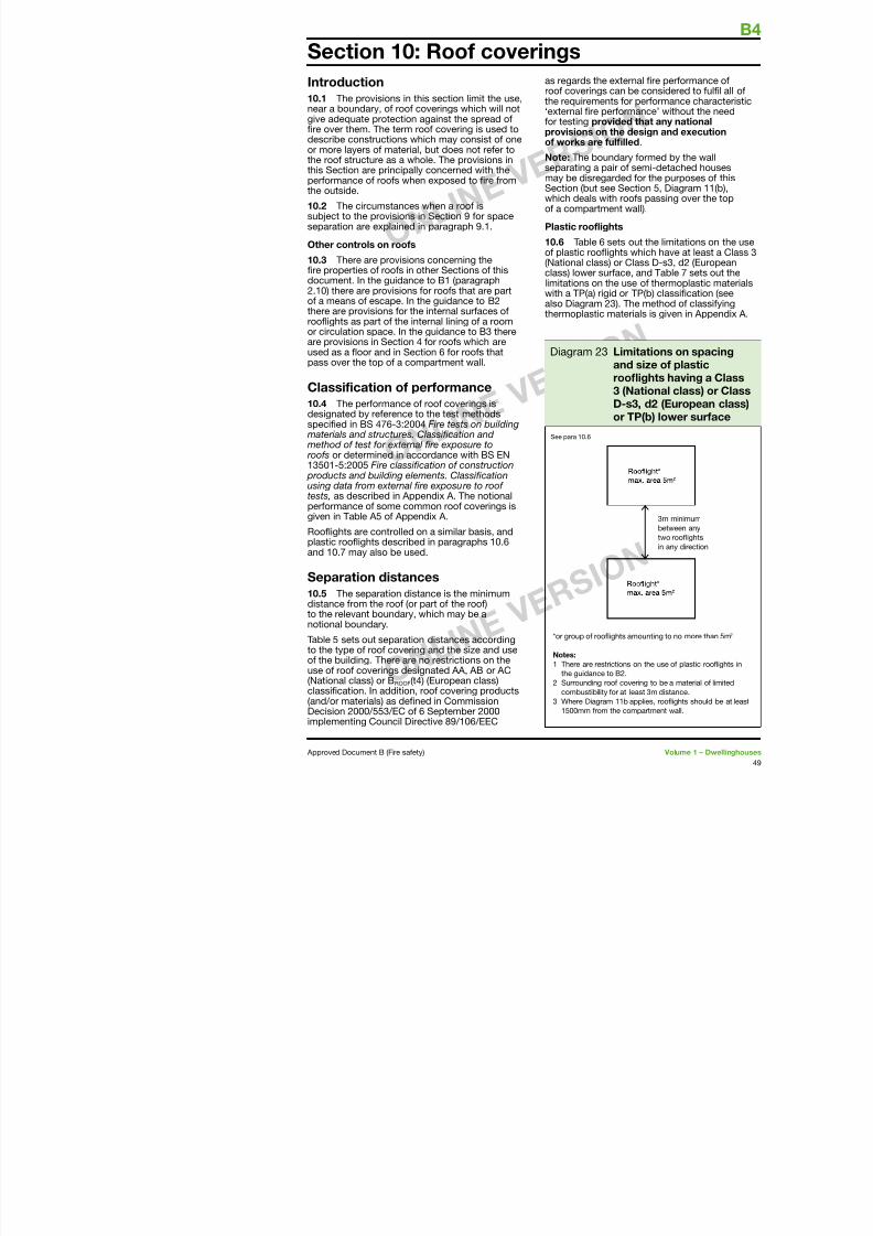
7/29/2019 Bldg_Reg_2006
http://slidepdf.com/reader/full/bldgreg2006 51/86
Introduction
10.1 The provisions in this section limit the use,
near a boundary, o roo coverings which will notgive adequate protection against the spread ore over them. The term roo covering is used todescribe constructions which may consist o oneor more layers o material, but does not reer tothe roo structure as a whole. The provisions inthis Section are principally concerned with theperormance o roos when exposed to re romthe outside.
10.2 The circumstances when a roo issubject to the provisions in Section 9 or spaceseparation are explained in paragraph 9..
Other controls on roos
10.3 There are provisions concerning there properties o roos in other Sections o thisdocument. In the guidance to B (paragraph2.0) there are provisions or roos that are part
o a means o escape. In the guidance to B2there are provisions or the internal suraces oroofights as part o the internal lining o a roomor circulation space. In the guidance to B3 thereare provisions in Section 4 or roos which areused as a foor and in Section 6 or roos thatpass over the top o a compartment wall.
Classiication o perormance
10.4 The perormance o roo coverings isdesignated by reerence to the test methodsspecied in BS 476-3:2004 Fire tests on building materials and structures. Classication and method o test or external re exposure to roos or determined in accordance with BS EN350-5:2005 Fire classication o construction products and building elements. Classicationusing data rom external re exposure to roo
tests, as described in Appendix A. The notionalperormance o some common roo coverings isgiven in Table A5 o Appendix A.
Roofights are controlled on a similar basis, andplastic roofights described in paragraphs 0.6and 0 7 may also be used
as regards the externroo coverings can bthe requirements or
‘external re perormor testing provided provisions on the do works are ullle
Note: The boundaryseparating a pair o smay be disregarded Section (but see Secwhich deals with roo
o a compartment w
Plastic roolights
10.6 Table 6 sets oo plastic roofights w(National class) or Cclass) lower surace,limitations on the usewith a TP(a) rigid or T
also Diagram 23). Ththermoplastic mater
Diagram 23 Limandroof3 (N
D-s3or T
See para 0.6
10.7 When used in roofights, a rigidthermoplastic sheet product made rom
Thatch and wood shingles
10 9 Thatch and wood shi
B4 ROOF COVERINGS
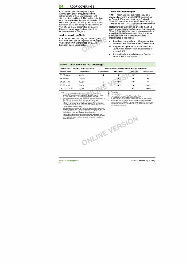
7/29/2019 Bldg_Reg_2006
http://slidepdf.com/reader/full/bldgreg2006 52/86
polycarbonate or rom unplasticised PVC,which achieves a Class (National class) ratingor surace spread o fame when tested to BS
476-7:997 (or 987 or 97) , or Class C-s3,d2(European class) can be regarded as having an AA (National class) designation or BROOF(t4)(European class) classication, other thanor the purposes o Diagram .
Unwired glass in roolights
10.8 When used in roofights, unwired glass atleast 4mm thick can be regarded as having an AA designation (National class) or BROOF(t4)(European class) classication.
10.9 Thatch and wood shiregarded as having an AD/Bor EROOF(t4) (European class)Table 5 i perormance unde
958) or BS EN 87:xxxx c
Note: Consideration can beroos being closer to the boTable 5 i, or example, the (based on Thatched building and extensions [the ‘Dorset incorporated in the design:
a. the raters are overdraw
having not less than 30 mb. the guidance given in A
Combustion appliances ollowed; and
c. the smoke alarm installaextends to the roo spac
Table 5 Limitations on roo coverings*Designation† o covering o roo or part o roo Minimum distance rom any point on rel
National Class European Class Less than 6m At least 6m At least 1
AA, AB or AC BROOF(t4) l l l
BA, BB or BC CROOF(t4) l l
CA, CB or CC DROOF(t4) () (2)l() (2) ()l()
AD, BD or CD EROOF(t4)() (2)
l
() (2) ()
l
()
DA, DB, DC or DD FROOF(t4)
Notes:
* See paragraph 0.8 or limitations on glass; paragraph 0.9 orlimitations on thatch and wood shingles; and paragraphs 0.6 and0.7 and Tables 6 and 7 or limitations on plastic roolights.
† The designation o external roo suraces is explained in Appendix A.(See Table A5 or notional designations o roo coverings.)
Separation distances do not apply to the boundary between rooso a pair o semi-detached houses (see para 0.5) and to enclosed/ covered walkways. However, see Diagram i the roo passes over
the top o a compartment wall.Openable polycarbonate and PVC roolights which achieve a Class (National class) or Class C-s3, d2 (European class) rating by test, seeparagraph 0.7, may be regarded as having an AA (National class)designation or BROOF(t4) (European class) classiication.
The National classiications do not automatically equate with theequivalent classiications in the European column, thereore productscannot typically assume a European class unless they have beentested accordingly
l Acceptable.
Not acceptable.
. Not acceptable on any o the ollowinga. Houses in terraces o three or moreb. Any other buildings with a cubic ca
2. Acceptable on buildings not listed in Nthe roo is no more than 3m² in area ansimilar part, with the roo between the o limited combustibility.
Table 6 Class 3 (National class) or Class D-s3,d2 (European climitations on use and boundary distance
ROOF COVERINGS
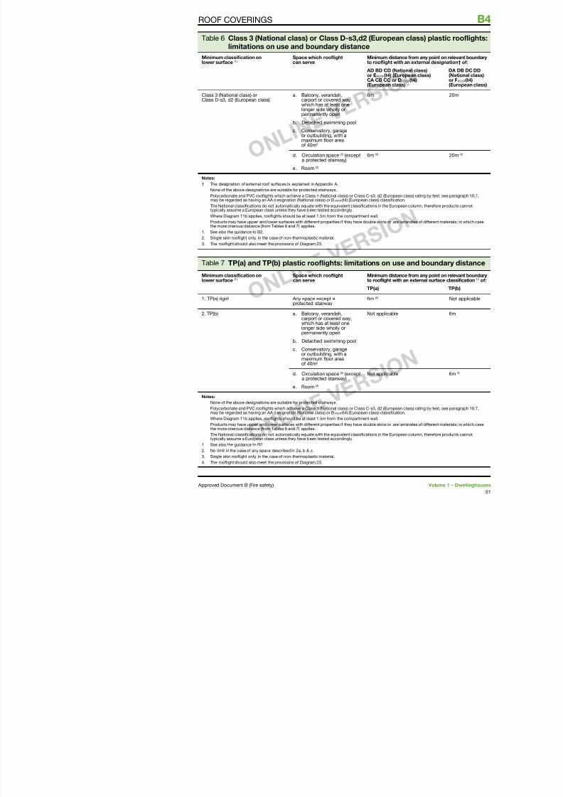
7/29/2019 Bldg_Reg_2006
http://slidepdf.com/reader/full/bldgreg2006 53/86
limitations on use and boundary distance
Minimum classiication onlower surace ()
Space which roolightcan serve
Minimum distance to roolight with an
AD BD CD (Nationor EROOF(t4) (EuropCA CB CC or DROO
(European class)
Class 3 (National class) orClass D-s3, d2 (European class)
a. Balcony, verandah,carport or covered way,which has at least onelonger side wholly orpermanently open
b. Detached swimming pool
c. Conservatory, garageor outbuilding, with amaximum loor areao 40m2
6m
d. Circulation space (2) (excepta protected stairway)
e. Room (2)
6m (3)
Notes:
† The designation o external roo suraces is explained in Appendix A.
None o the above designations are suitable or protected stairways.
Polycarbonate and PVC roolights which achieve a Class (National class) or Class C-s3, d2 (European clmay be regarded as having an AA designation (National class) or BROOF(t4) (European class) classiication.
The National classiications do not automatically equate with the equivalent classiications in the Europeantypically assume a European class unless they have been tested accordingly.
Where Diagram b applies, roolights should be at least .5m rom the compartment wall.
Products may have upper and lower suraces with dierent properties i they have double skins or are lamthe more onerous distance (rom Tables 6 and 7) applies.
. See also the guidance to B2.
2. Single skin roolight only, in the case o non-thermoplastic material.
3. The roolight should also meet the provisions o Diagram 23.
Table 7 TP(a) and TP(b) plastic roolights: limitations on use a
Minimum classiication onlower surace ()
Space which roolightcan serve
Minimum distance to roolight with an
TP(a)
. TP(a) rigid Any space except aprotected stairway
6m (2)
2. TP(b)
a. Balcony, verandah,carport or covered way,which has at least onelonger side wholly orpermanently open
b. Detached swimming pool
c. Conservatory, garageor outbuilding, with a
i l
Not applicable
The RequirementB5 ACCESS AND FACILITIES FOR THE FIRE AND RESC
7/29/2019 Bldg_Reg_2006
http://slidepdf.com/reader/full/bldgreg2006 54/86
This Approved Document deals with theollowing Requirement rom Part B o Schedule to the Building Regulations 2000 (as amended).
Requirement Limitsonapplication
Access and facilities for the f ire service
B5. (1) The building shall be designed and constructed so
as to provide reasonable facilities to assist firefighters inthe protection of life.
(2) Reasonable provision shall be made within the site
of the building to enable fire appliances to gain access to
the building.
Guidance
7/29/2019 Bldg_Reg_2006
http://slidepdf.com/reader/full/bldgreg2006 55/86
Perormance
In the Secretary o State’s view the Requirements
o B5 will be met:a. i there is sucient means o external access
to enable re appliances to be brought nearto the building or eective use;
b. i there is sucient means o access into,and within, the building or reghtingpersonnel to eect search and rescueand ght re;
c. i the building is provided with sucientinternal re mains and other acilities toassist reghters in their tasks; and
d. i the building is provided with adequatemeans or venting heat and smoke roma re in a basement.
These access arrangements and acilities areonly required in the interests o the health andsaety o people in and around the building. Theextent to which they are required will depend onthe use and size o the building in so ar as itaects the health and saety o those people.
Introduction
B5.i The main actor determining the acilitiesneeded to assist the re and rescue service is thesize o the building. Generally speaking reghting
is carried out within the building.For dwellinghouses, it is usually only necessaryto ensure that the building is suciently closeto a point accessible to re and rescue servicevehicles (see paragraph .2). For very largehouses additional measures may be necessary.The guidance given in Approved Document B Volume 2 (Buildings other than dwellinghouses)may be applicable.
I it is proposed to deviate rom the generalguidance in Section then it would be advisableto seek advice rom the Fire and Rescue Serviceat the earliest opportunity.
Section 11: Vehicle accessB5
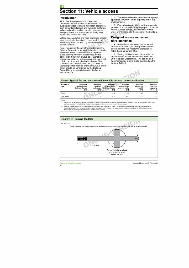
7/29/2019 Bldg_Reg_2006
http://slidepdf.com/reader/full/bldgreg2006 56/86
Introduction
11.1 For the purposes o this Approved
Document, vehicle access to the exterior o abuilding is needed to enable high reach appliances,such as turntable ladders and hydraulic platorms,to be used and to enable pumping appliancesto supply water and equipment or reghting,search and rescue activities.
Vehicle access routes and hard-standings shouldmeet the criteria described in paragraph .4where they are to be used by re and rescue
service vehicles.Note: Requirements cannot be made under theBuilding Regulations or work to be done outsidethe site o the works shown on the depositedplans, building notice or initial notice. In thisconnection it may not always be reasonable toupgrade an existing route across a site to a smallbuilding such as a single dwellinghouse. Theoptions in such a case, rom doing no work to
upgrading certain eatures o the route, e.g. a sharpbend, should be considered by the BuildingControl Body in consultation with the re andrescue service.
11.2 There should be vehiappliance to within 45m o adwellinghouse.
11.3 Every elevation to whprovided in accordance with have a suitable door(s), not wide, giving access to the in
Design o access ro
hard-standings
11.4 A vehicle access routor other route which, includcovers and the like, meets tTable 8 and paragraph .5
11.5 Turning acilities shouany dead end access route 20m long (see Diagram 24). hammerhead or turning circbasis o Table 8.
Table 8 Typical ire and rescue service vehicle access route specii
Appliancetype
Minimumwidth o road
between kerbs(m)
Minimumwidth o
gateways(m)
Minimumturning circle
between kerbs(m)
Minimumturning circle
between walls(m)
Mcle
Pump 3.7 3. 6.8 9.2
High reach 3.7 3. 26.0 29.0
Notes:
. Fire appliances are not standardised. Some ire and rescue services have appliances o greater weight or dierent sizand Rescue Authority, the Building Control Body may adopt other dimensions in such circumstances.
2. Because the weight o high reach appliances is distributed over a number o axles, it is considered that their inreque
or route designed to 2.5 tonnes should not cause damage. It would thereore be reasonable to design the roadbasestructures such as bridges should have the ull 7 tonnes capacity.
Diagram 24 Turning acilities
Appendix A: Perormance o matproducts and structures
7/29/2019 Bldg_Reg_2006
http://slidepdf.com/reader/full/bldgreg2006 57/86
Introduction1. Much o the guidance in this documentis given in terms o perormance in relation toBritish or European Standards or products ormethods o test or design or in terms o EuropeanTechnical Approvals. In such cases the material,product or structure should:
a. be in accordance with a specication ordesign which has been shown by test to be
capable o meeting that perormance; orNote: For this purpose, laboratories accreditedby the United Kingdom Accreditation Service(UKAS) or conducting the relevant tests wouldbe expected to have the necessary expertise.
b. have been assessed rom test evidenceagainst appropriate standards, or by usingrelevant design guides, as meeting that
perormance; orNote: For this purpose, laboratories accreditedby UKAS or conducting the relevant tests andsuitably qualied re saety engineers might beexpected to have the necessary expertise.
For materials/products where European standardsor approvals are not yet available and or atransition period ater they become available,British standards may continue to be used.
Any body notied to the UK Government bythe Government o another Member State o theEuropean Union as capable o assessing suchmaterials/products against the relevant BritishStandards, may also be expected to have thenecessary expertise. Where European materials/ products standards or approvals are available,any body notied to the European Commissionas competent to assess such materials or products
against the relevant European standards ortechnical approval can be considered to havethe appropriate expertise.
c. where tables o notional perormance areincluded in this document, conorm with anappropriate specication given in these
• Timber – BRE 45rame buildings –ISBN: 8608 6
• Steel – SCI P97re saety: A hanengineers 999 I
Note 2: Any test evidthe re resistance rabe careully checked
compliance that is athe intended use. Sm(such as xing meththe introduction o insignicantly aect th
2. Building Reguin buildings as a wholimiting re hazard.
The aim o standard
or assess the responstructure or system tbehaviour. Standard measure re hazard.number o actors thaccount. Other actors
Fire resistance
3. Factors havinthat are considered i
a. re severity;
b. building height; a
c. building occupan
4. The standardsbased on assumptioand the consequencFire severity is estimrom the use o the bon the assumption t(which constitute thebuildings in the sam
products and structures
e. whether the building is o single storeyconstruction (where escape is direct andstructural ailure is unlikely to precede
Table A1 gives the speciceach element in terms o oollowing perormance cri
B PERFORMANCE OF MATERIALS, PRODUCTS AND
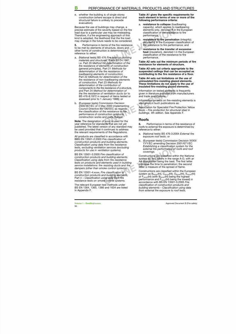
7/29/2019 Bldg_Reg_2006
http://slidepdf.com/reader/full/bldgreg2006 58/86
y pevacuation).
Because the use o buildings may change, a
precise estimate o re severity based on the reload due to a particular use may be misleading.Thereore, i a re engineering approach o thiskind is adopted, the likelihood that the re loadmay change in the uture needs to be considered.
5. Perormance in terms o the re resistanceto be met by elements o structure, doors andother orms o construction is determined byreerence to either:
a. (National tests) BS 476 Fire tests on building materials and structures, Parts 20-24:987,i.e. Part 20 Method or determination o there resistance o elements o construction(general principles), Part 2 Methods or determination o the re resistance o loadbearing elements o construction,Part 22 Methods or determination o there resistance o non-loadbearing elements
o construction, Part 23 Methods or determination o the contribution o components to the re resistance o a structure,and Part 24 Method or determination o the re resistance o ventilation ducts (or toBS 476-8:972 in respect o items tested orassessed prior to January 988); or
b. (European tests) Commission Decision2000/367/EC o 3 May 2000 implementing
Council Directive 89/06/EEC as regardsthe classication o the resistance to reperormance o construction products,construction works and parts thereo.
Note: The designation o xxxx is used or theyear reerence or standards that are not yetpublished. The latest version o any standard maybe used provided that it continues to addressthe relevant requirements o the Regulations.
All products are classied in accordance withBBS EN 350-2:2003 Fire classication o construction products and building elements.Classication using data rom re resistancetests, excluding ventilation services (excluding
d t i til ti t )
g p
a. resistance to collapsecapacity), which applies
elements only, denoted classication o the resisperormance;
b. resistance to re penedenoted E in the Europethe resistance to re per
c. resistance to the transheat (insulation), denoteclassication o the resisperormance.
Table A2 sets out the miniresistance or elements o
Table A3 sets out criteria suspended ceilings that ccontributing to the re res
Table A4 sets out limitatiouninsulated re-resisting gThese limitations do not ainsulated re-resisting gla
Inormation on tested elemegiven in literature available and trade associations.
Inormation on tests on re-also given in such publicatio
Association or Specialist FBook – Fire protection or s buildings, 4th edition. See A
Roos
6. Perormance in termsroos to external re exposureerence to either:
a. (National tests) BS 476-exposure roo tests; or
b. (European tests) CommYYY/EC amending DeciEstablishing a classicatexternal re perormanc
BS EN 350-5 reers to our separate tests. Thesux (t4) used above indicates that Test 4 is to beused or the purposes o this Approved Document.
• BS EN ISO 925or building produ subjected to dire
PERFORMANCE OF MATERIALS, PRODUCTS AND STR
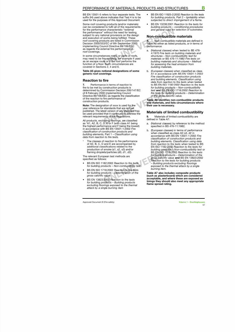
7/29/2019 Bldg_Reg_2006
http://slidepdf.com/reader/full/bldgreg2006 59/86
p p pp
Some roo covering products (and/or materials)can be considered to ull all o the requirements
or the perormance characteristic “externalre perormance” without the need or testing,subject to any national provisions on the designand execution o works being ullled. Theseroo covering products are listed in CommissionDecision 2000/553/EC o 6th September 2000implementing Council Directive 89/06/EECas regards the external re perormance oroo coverings.
In some circumstances roos, or parts o roos,may need to be re-resisting, or example i usedas an escape route or i the roo perorms theunction o a foor. Such circumstances arecovered in Sections 2, 4 and 6.
Table A5 gives notional designations o somegeneric roo coverings.
Reaction to ire7. Perormance in terms o reaction tore to be met by construction products isdetermined by Commission Decision 200/47/ECo 8 February 2000 implementing CouncilDirective 89/06/EEC as regards the classicationo the reaction to re perormance oconstruction products.
Note: The designation o xxxx is used or the
year reerence or standards that are not yetpublished. The latest version o any standard maybe used provided that it continues to address therelevant requirements o the Regulations.
All products, excluding foorings, are classiedas † A, A2, B, C, D, E or F (with class A beingthe highest perormance and F being the lowest)in accordance with BS EN 350-:2002 Fireclassication o construction products and
building elements, Part – Classication usingdata rom reaction to re tests.
† The classes o reaction to re perormanceo A2, B, C, D and E are accompanied byadditional classications related to the
d ti k ( 2 3) d/
j
• BS EN 3238:20 building products
and general rules
Non-combusti
8. Non-combustTable A6 either as lisperormance:
a. (National classes4:970 Fire tests
structures – Non materials or BS 4 building materialsor assessing the building materials
b. (European classe A in accordanceFire classication and building elem
data rom reactioto BS EN ISO or building prodtest and BS EN re tests or buildo the gross calo
Table A6 identies and materials, and their use is necessa
Materials o lim
9. Materials o limdened in Table A7:
a. (National classesspecied in BS 4
b. (European classe
when classied aaccordance withclassication o c building elementsrom reaction to EN ISO 82:200b ildi d t
Internal linings
10. Flame spread over wall or ceiling suracesis controlled by providing or the lining materials
16. Results o tests on pare requently given in literamanuacturers and trade as
B PERFORMANCE OF MATERIALS, PRODUCTS AND
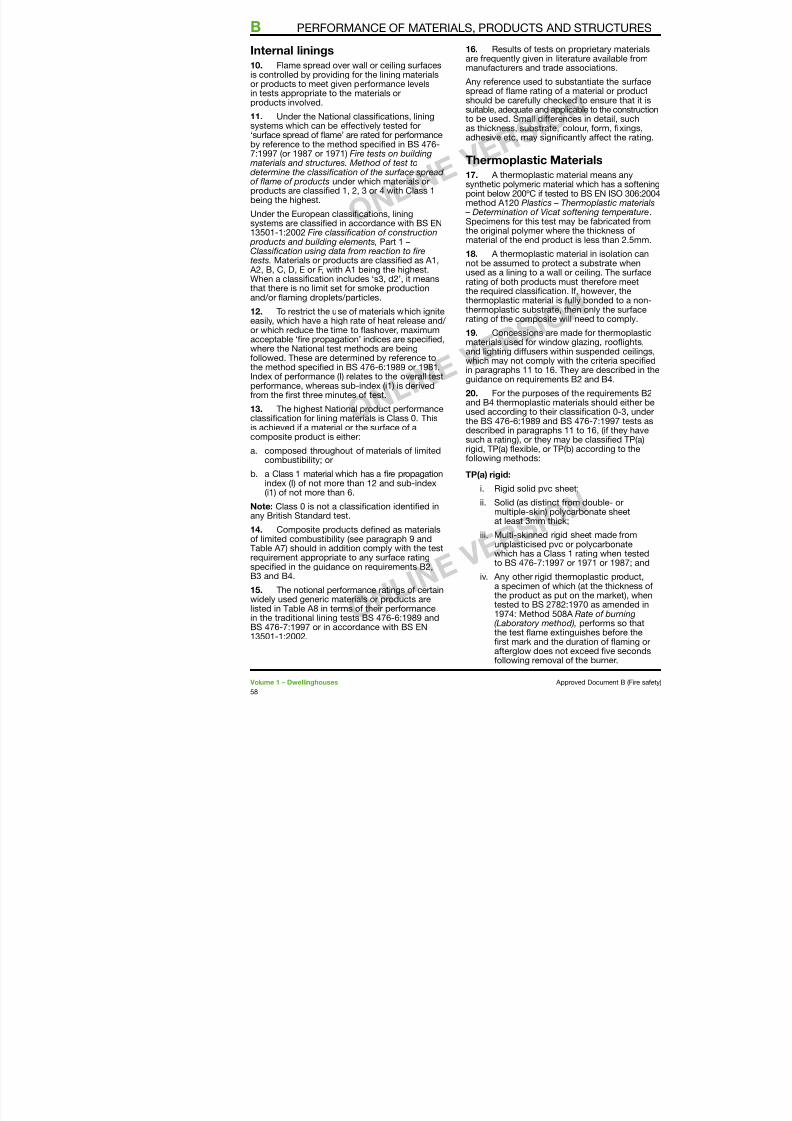
7/29/2019 Bldg_Reg_2006
http://slidepdf.com/reader/full/bldgreg2006 60/86
is controlled by providing or the lining materialsor products to meet given perormance levelsin tests appropriate to the materials or
products involved.
11. Under the National classications, liningsystems which can be eectively tested or‘surace spread o fame’ are rated or perormanceby reerence to the method specied in BS 476-7:997 (or 987 or 97) Fire tests on building materials and structures. Method o test todetermine the classication o the surace spread o fame o products under which materials or
products are classied , 2, 3 or 4 with Class being the highest.
Under the European classications, liningsystems are classied in accordance with BS EN350-:2002 Fire classication o construction products and building elements, Part –Classication using data rom reaction to retests. Materials or products are classied as A, A2, B, C, D, E or F, with A being the highest.
When a classication includes ‘s3, d2’, it meansthat there is no limit set or smoke productionand/or faming droplets/particles.
12. To restrict the use o materials which igniteeasily, which have a high rate o heat release and/ or which reduce the time to fashover, maximumacceptable ‘re propagation’ indices are specied,where the National test methods are beingollowed. These are determined by reerence to
the method specied in BS 476-6:989 or 98.Index o perormance (I) relates to the overall testperormance, whereas sub-index (i) is derivedrom the rst three minutes o test.
13. The highest National product perormanceclassication or lining materials is Class 0. Thisis achieved i a material or the surace o acomposite product is either:
a. composed throughout o materials o limitedcombustibility; or
b. a Class material which has a re propagationindex (I) o not more than 2 and sub-index(i) o not more than 6.
Any reerence used to subsspread o fame rating o a m
should be careully checkedsuitable, adequate and applicato be used. Small dierenceas thickness, substrate, coladhesive etc, may signican
Thermoplastic Mate
17. A thermoplastic matesynthetic polymeric material point below 200ºC i tested tomethod A20 Plastics – The – Determination o Vicat soSpecimens or this test maythe original polymer where tmaterial o the end product
18. A thermoplastic matenot be assumed to protect aused as a lining to a wall or rating o both products musthe required classication. Ithermoplastic material is ulthermoplastic substrate, therating o the composite will
19. Concessions are madmaterials used or window gand lighting diusers within which may not comply with in paragraphs to 6. Theguidance on requirements B
20. For the purposes o tand B4 thermoplastic materused according to their clasthe BS 476-6:989 and BS described in paragraphs such a rating), or they may brigid, TP(a) fexible, or TP(b)ollowing methods:
TP(a) rigid:
i. Rigid solid pvc shee
ii Solid (as distinct rom
TP(a) lexible:
Flexible products not more than mm thickwhich comply with the Type C requirements
Note: I it is not poss3mm-thick specimen3mm test specimen
t i l th
PERFORMANCE OF MATERIALS, PRODUCTS AND STR
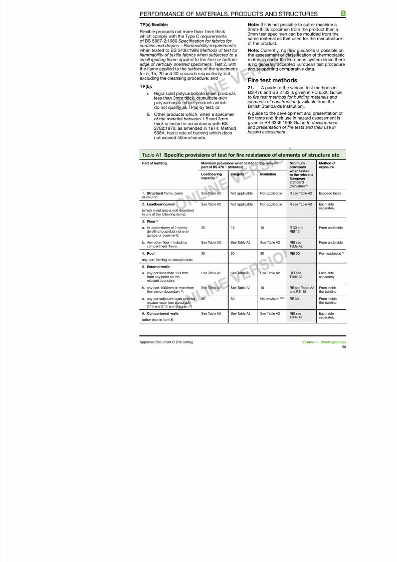
7/29/2019 Bldg_Reg_2006
http://slidepdf.com/reader/full/bldgreg2006 61/86
which comply with the Type C requirementso BS 5867-2:980 Specication or abrics or curtains and drapes – Flammability requirements
when tested to BS 5438:989 Methods o test or fammability o textile abrics when subjected to a small igniting fame applied to the ace or bottomedge o vertically oriented specimens, Test 2, withthe fame applied to the surace o the specimensor 5, 5, 20 and 30 seconds respectively, butexcluding the cleansing procedure; and
TP(b):
i. Rigid solid polycarbonate sheet productsless than 3mm thick, or multiple-skinpolycarbonate sheet products whichdo not qualiy as TP(a) by test; or
ii. Other products which, when a specimeno the material between .5 and 3mmthick is tested in accordance with BS2782:970, as amended in 974: Method508A, has a rate o burning which does
not exceed 50mm/minute.
same material as thao the product.
Note: Currently, no nthe assessment or cmaterials under the Eis no generally accepand supporting com
Fire test metho
21. A guide to theBS 476 and BS 2782to re test methods elements o construcBritish Standards Ins
A guide to the develore tests and their usgiven in BS 6336:99 and presentation o hazard assessment.
Table A Speciic provisions o test or ire resistance o elem
Part o building Minimum provisions when tested to the relevantpart o BS 476 () (minutes)
Loadbearingcapacity (2)
Integrity Insulation
. Structural rame, beamor column.
See Table A2 Not applicable Not applicable
2. Loadbearing wall
(which is not also a wall describedin any o the ollowing items).
See Table A2 Not applicable Not applicable
3. Floor (3)
a. In upper storey o 2-storeydwellinghouse (but not overgarage or basement);
30 5 5
b. Any other loor – includingcompartment loors.
See Table A2 See Table A2 See Table A2
Table A continued
Part o building Minimum provisions when tested to the relevant( )
Minimum
B PERFORMANCE OF MATERIALS, PRODUCTS AND
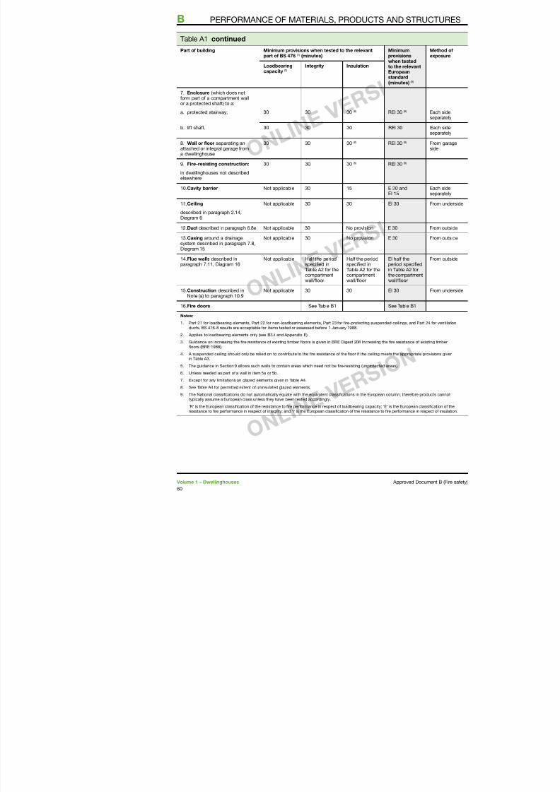
7/29/2019 Bldg_Reg_2006
http://slidepdf.com/reader/full/bldgreg2006 62/86
part o BS 476 () (minutes) provisiowhen teto the re
Europeastandard(minutes
Loadbearing
capacity (2)
Integrity Insulation
7. Enclosure (which does notorm part o a compartment wallor a protected shat) to a:
a. protected stairway;
30
30
30 (8)
REI 30 (8)
b. lit shat. 30 30 30 REI 30
8. Wall or loor separating anattached or integral garage roma dwellinghouse
30 30 30 (8) REI 30 (8)
9. Fire-resisting construction:
in dwellinghouses not describedelsewhere
30 30 30 (8) REI 30 (8)
0.Cavity barrier Not applicable 30 5 E 30 andEI 5
.Ceiling
described in paragraph 2.4,Diagram 6
Not applicable 30 30 EI 30
2.Duct described in paragraph 6.8e Not applicable 30 No provision E 30
3.Casing around a drainagesystem described in paragraph 7.8,Diagram 5
Not applicable 30 No provision E 30
4.Flue walls described inparagraph 7., Diagram 6
Not applicable Hal the periodspeciied inTable A2 or thecompartmentwall/loor
Hal the periodspeciied inTable A2 or thecompartmentwall/loor
EI hal thperiod sin Table Athe compwall/loo
5.Construction described inNote (a) to paragraph 0.9
Not applicable 30 30 EI 30
6.Fire doors See Table B See Tabl
Notes:
. Part 2 or loadbearing elements, Part 22 or non-loadbearing elements, Part 23 or ire-protecting suspended ceilingducts. BS 476-8 results are acceptable or items tested or assessed beore January 988.
2. Applies to loadbearing elements only (see B3.ii and Appendix E).
3. Guidance on increasing the ire resistance o existing timber loors is given in BRE Digest 208 Increasing the ire resisloors (BRE 988).
4 A suspended ceiling should only be relied on to contribute to the ire resistance o the loor i the ceiling meets the ap
Table A2 Minimum periods o ire resistance or dwellinghous
Minimum periods (minutes) or elements o structure in a:
PERFORMANCE OF MATERIALS, PRODUCTS AND STR
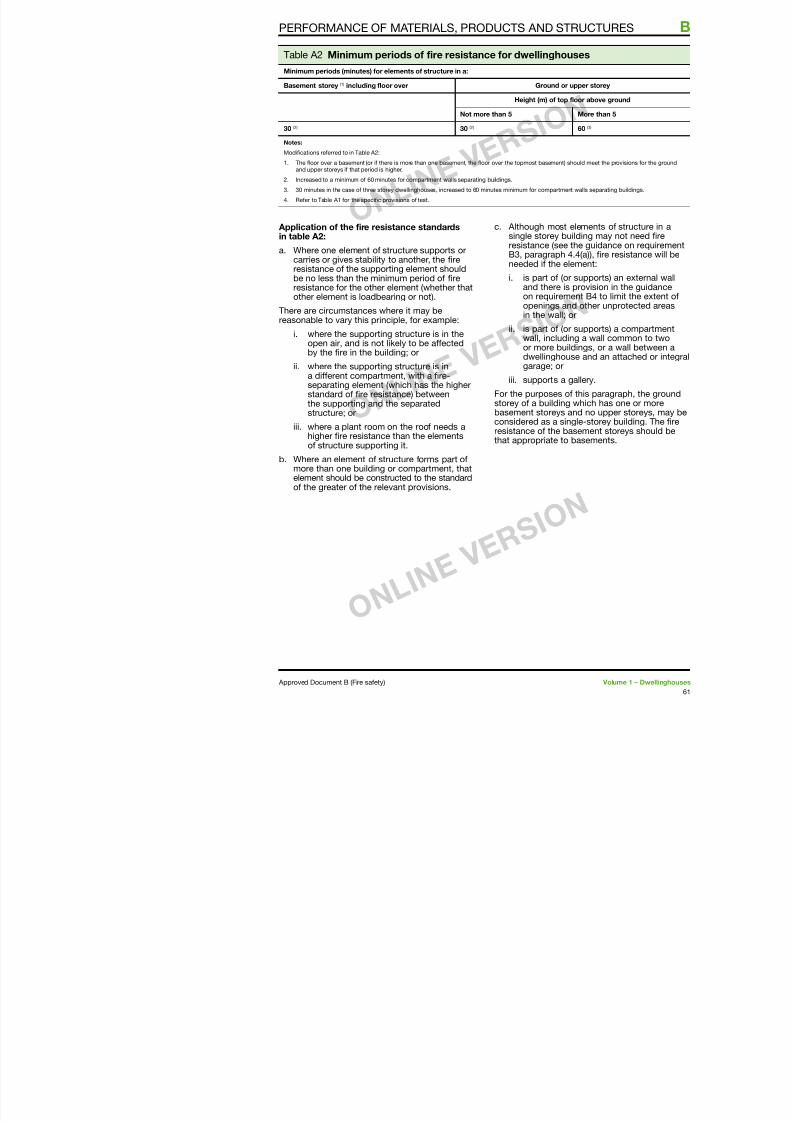
7/29/2019 Bldg_Reg_2006
http://slidepdf.com/reader/full/bldgreg2006 63/86
Basement storey () including loor over Ground or up
Height (m) o top l
Not more than 5
30 (2) 30 (2)
Notes:
Modiications reerred to in Table A2:
. The loor over a basement (or i there is more than one basement, the loor over the topmost basement) shand upper storeys i that period is higher.
2. Increased to a minimum o 60 minutes or compartment walls separating buildings.
3. 30 minutes in the case o three storey dwellinghouses, increased to 60 minutes minimum or compartment
4. Reer to Table A or the speciic provisions o test.
Application o the ire resistance standardsin table A2:
a. Where one element o structure supports orcarries or gives stability to another, the reresistance o the supporting element should
be no less than the minimum period o reresistance or the other element (whether thatother element is loadbearing or not).
There are circumstances where it may bereasonable to vary this principle, or example:
i. where the supporting structure is in theopen air, and is not likely to be aectedby the re in the building; or
ii. where the supporting structure is ina dierent compartment, with a re-separating element (which has the higherstandard o re resistance) betweenthe supporting and the separatedstructure; or
iii. where a plant room on the roo needs ahigher re resistance than the elementso structure supporting it.
b. Where an element o structure orms part omore than one building or compartment, thatelement should be constructed to the standardo the greater o the relevant provisions.
c. Although most esingle storey buiresistance (see thB3, paragraph 4.needed i the ele
i. is part o (or and there is pon requiremeopenings andin the wall; or
ii. is part o (or wall, includinor more builddwellinghous
garage; oriii. supports a ga
For the purposes o storey o a building wbasement storeys anconsidered as a singresistance o the basthat appropriate to b
Table A3 Limitations on ire-protecting suspended ceilings (see Tab
Height o building orseparated part (m)
Type o loor Provision or ire resistanceo loor (minutes)
Dessus
B PERFORMANCE OF MATERIALS, PRODUCTS AND
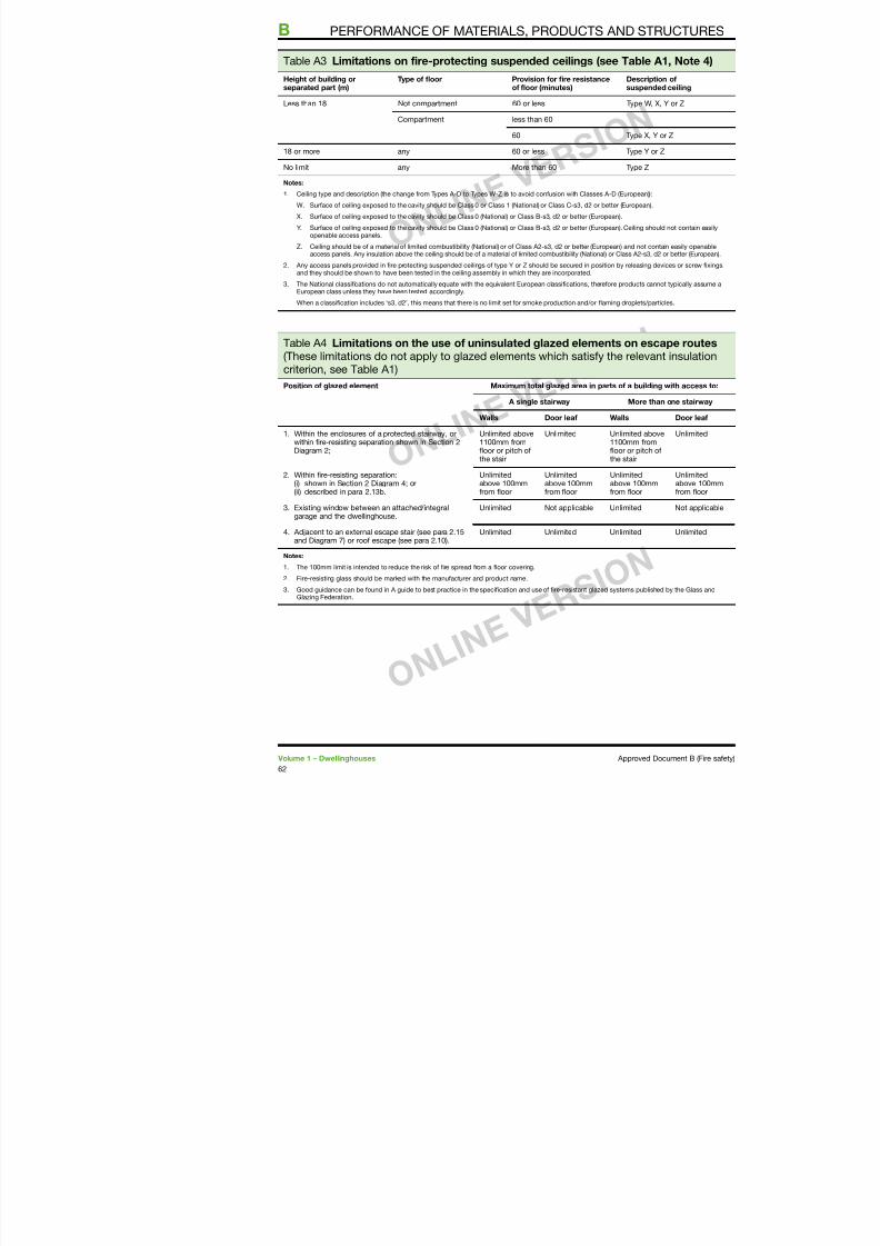
7/29/2019 Bldg_Reg_2006
http://slidepdf.com/reader/full/bldgreg2006 64/86
separated part (m) o loor (minutes) sus
Less than 8 Not compartment 60 or less Typ
Compartment less than 60
60 Typ
8 or more any 60 or less Typ
No limit any More than 60 Typ
Notes:
. Ceiling type and description (the change rom Types A-D to Types W-Z is to avoid conusion with Classes A-D (Europ
W. Surace o ceiling exposed to the cavity should be Class 0 or Class (National) or Class C-s3, d2 or better (Euro
X. Surace o ceiling exposed to the cavity should be Class 0 (National) or Class B-s3, d2 or better (European).
Y. Surace o ceiling exposed to the cavity should be Class 0 (National) or Class B-s3, d2 or better (European). Ceilopenable access panels.
Z. Ceiling should be o a material o limited combustibility (National) or o Class A2-s3, d2 or better (European) andaccess panels. Any insulation above the ceiling should be o a material o limited combustibility (National) or Class A
2. Any access panels provided in ire protecting suspended ceilings o type Y or Z should be secured in position by releand they should be shown to have been tested in the ceiling assembly in which they are incorporated.
3. The National classiications do not automatically equate with the equivalent European classiications, thereore produEuropean class unless they have been tested accordingly.
When a classiication includes ‘s3, d2’, this means that there is no limit set or smoke production and/or laming drop
Table A4 Limitations on the use o uninsulated glazed elements on (These limitations do not apply to glazed elements which satisy the relcriterion, see Table A)
Position o glazed element Maximum total glazed area in parts o a b
A single stairway Mo
Walls Door lea Walls
. Within the enclosures o a protected stairway, orwithin ire-resisting separation shown in Section 2Diagram 2;
Unlimited above00mm romloor or pitch othe stair
Unlimited Unlimited00mmloor or pthe stair
2. Within ire-resisting separation:(i) shown in Section 2 Diagram 4; or(ii) described in para 2.3b.
Unlimitedabove 00mmrom loor
Unlimitedabove 00mmrom loor
Unlimiteabove 0rom loo
3. Existing window between an attached/integralgarage and the dwellinghouse.
Unlimited Not applicable Unlimited
4. Adjacent to an external escape stair (see para 2.5and Diagram 7) or roo escape (see para 2.0).
Unlimited Unlimited Unlimited
Notes:
Table A5 Notional designations o roo coverings
Part i: Pitched roos covered with slates or tiles
PERFORMANCE OF MATERIALS, PRODUCTS AND STR
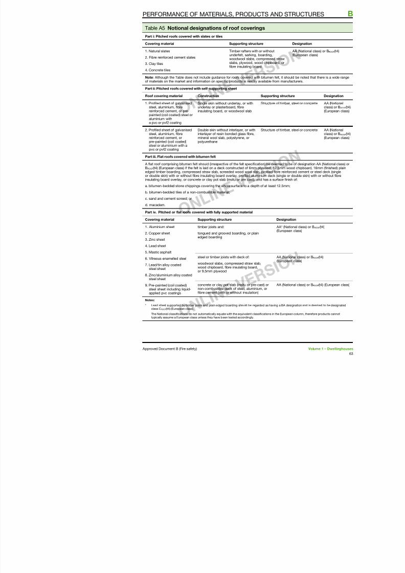
7/29/2019 Bldg_Reg_2006
http://slidepdf.com/reader/full/bldgreg2006 65/86
Covering material Supporting structure D
. Natural slates2. Fibre reinorced cement slates
3. Clay tiles
4. Concrete tiles
Timber raters with or withoutunderelt, sarking, boarding,woodwool slabs, compressed strawslabs, plywood, wood chipboard, oribre insulating board
A(E
Note: Although the Table does not include guidance or roos covered with bitumen elt, it shouldo materials on the market and inormation on speciic products is readily available rom manuac
Part ii: Pitched roos covered with sel-supporting sheet
Roo covering material Construction Supporting structure
. Proiled sheet o galvanisedsteel, aluminium, ibrereinorced cement, or pre-painted (coil coated) steel oraluminium witha pvc or pv2 coating
Single skin without underlay, or withunderlay or plasterboard, ibreinsulating board, or woodwool slab
Structure o timber, st
2. Proiled sheet o galvanisedsteel, aluminium, ibrereinorced cement, or
pre-painted (coil coated)steel or aluminium with apvc or pv2 coating
Double skin without interlayer, or withinterlayer o resin bonded glass ibre,mineral wool slab, polystyrene, or
polyurethane
Structure o timber, st
Part iii. Flat roos covered with bitumen elt
A lat roo comprising bitumen elt should (irrespective o the elt speciication) be deemed to be BROOF(t4) (European class) i the elt is laid on a deck constructed o 6mm plywood, 2.5mm woodedged timber boarding, compressed straw slab, screeded wood wool slab, proiled ibre reinorceor double skin) with or without ibre insulating board overlay, proiled aluminium deck (single or dinsulating board overlay, or concrete or clay pot slab (insitu or pre cast), and has a surace inish
a. bitumen-bedded stone chippings covering the whole surace to a depth o at least 2.5mm;b. bitumen-bedded tiles o a non-combustible material;
c. sand and cement screed; or
d. macadam.
Part iv. Pitched or lat roos covered with ully supported material
Covering material Supporting structure Designatio
. Aluminium sheet
2. Copper sheet
3. Zinc sheet
4. Lead sheet
5. Mastic asphalt
timber joists and:
tongued and grooved boarding, or plainedged boarding
AA* (Nation
(European c
steel or timber joists with deck o: AA (Nationa
Table A6 Use and deinitions o non-combustible materials
Reerences in AD B guidance tosituations where such materials
Deinitions o non-combustible mate
B PERFORMANCE OF MATERIALS, PRODUCTS AND
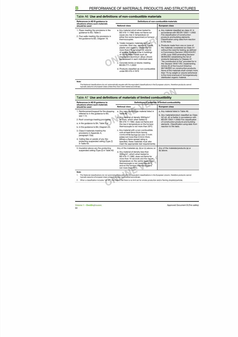
7/29/2019 Bldg_Reg_2006
http://slidepdf.com/reader/full/bldgreg2006 66/86
s ua o s e e suc a e a sshould be used National class European clas
. Pipes meeting the provisions in theguidance to B3, Table 3.
2. Flue walls meeting the provisions inthe guidance to B3, Diagram 6.
a. Any material which when tested toBS 476-:982 does not lame norcause any rise in temperature oneither the centre (specimen) or urnacethermocouples
b. Totally inorganic materials such asconcrete, ired clay, ceramics, metals,plaster and masonry containing notmore than % by weight or volumeo organic material. (Use in buildingso combustible metals such as
magnesium/aluminium alloys shouldbe assessed in each individual case).
c. Concrete bricks or blocks meetingBS EN 77-:2003
d. Products classiied as non-combustibleunder BS 476-4:970
a. Any material accordance wFire classiica products andClassiicationto ire tests.
b. Products mathe materialswithout the nin Commissioo 6th June 2
96/603/EC eproducts bel“No contributhe Decision Article 20 o 89/06/EEC None o the mthan % by wis the more odistributed o
Note:
The National classiications do not automatically equate with the equivalent classiications in the European column, ttypically assume a European class unless they have been tested accordingly.
Table A7 Use and deinitions o materials o limited combustibility
Reerences in AD B guidance tosituations where such materialsshould be used
Deinitions o materials o limited combu
National class European clas
. Reinorcement/support or ire-stoppingreerred to in the guidance to B3,see 7.3.
2. Roo coverings meeting provisions:
a. in the guidance to B4, Table 5 or
b. in the guidance to B4, Diagram 23.
3. Class 0 materials meeting theprovisions in Appendix A,paragraph 3(a).
4. Ceiling tiles or panels o any ire-protecting suspended ceiling (Type Z)in Table A3.
a. Any non-combustible material listed inTable A6.
b. Any material o density 300/kg/m3 or more, which when tested toBS 476-:982, does not lame andthe rise in temperature on the urnacethermocouple is not more than 20ºC.
c. Any material with a non-combustiblecore at least 8mm thick havingcombustible acings (on one or both
sides) not more than 0.5mm thick.(Where a lame spread rating isspeciied, these materials must alsomeet the appropriate test requirements).
a. Any material
b. Any material/ A2-s3, d2 orBS EN 350o constructielements. Cla reaction to i
5. Insulation above any ire-protectingsuspended ceiling (Type Z) in Table A3.
Any o the materials (a), (b) or (c) above, or: Any o the mate(b) above.
Table A8 Typical perormance ratings o some generic mater
Rating Material or product
PERFORMANCE OF MATERIALS, PRODUCTS AND STR
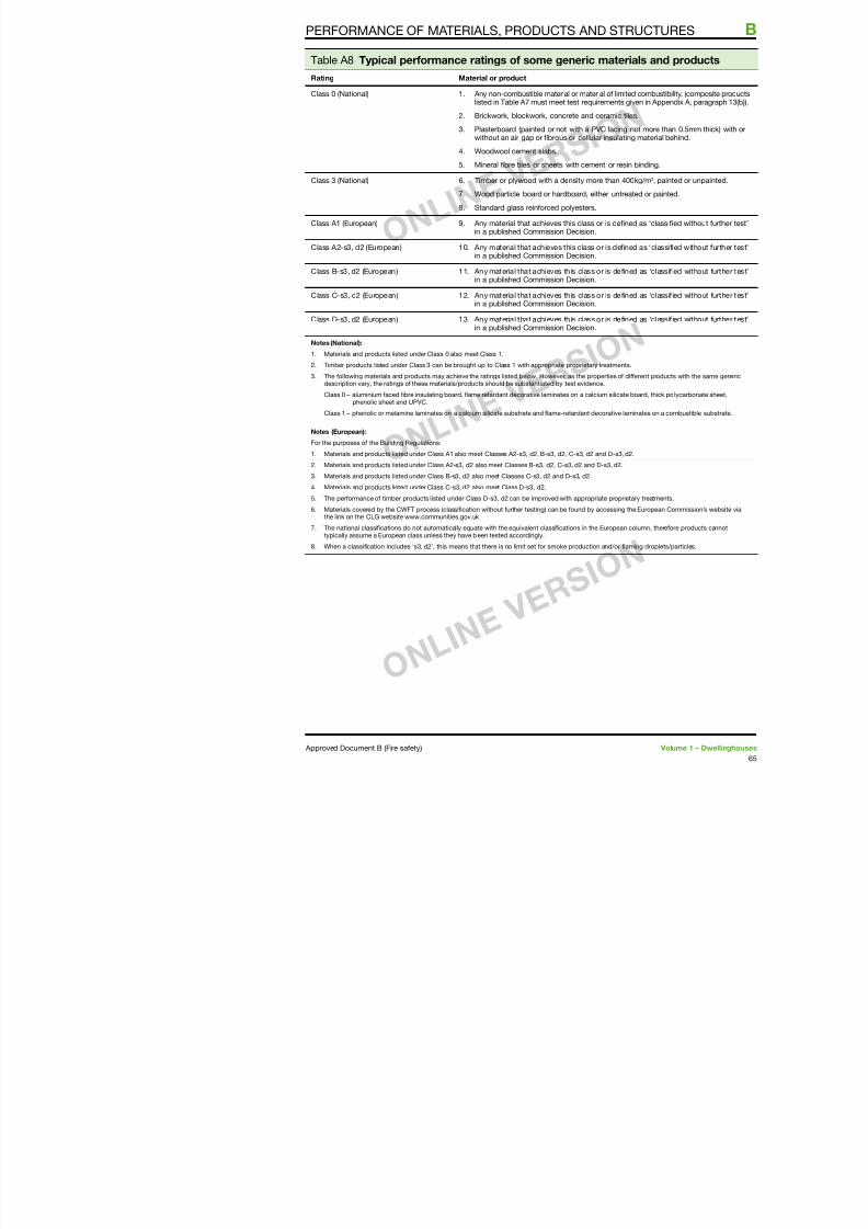
7/29/2019 Bldg_Reg_2006
http://slidepdf.com/reader/full/bldgreg2006 67/86
Class 0 (National) . Any non-combustible material or material o limitelisted in Table A7 must meet test requirements g
2. Brickwork, blockwork, concrete and ceramic til
3. Plasterboard (painted or not with a PVC acing without an air gap or ibrous or cellular insulatin
4. Woodwool cement slabs.
5. Mineral ibre tiles or sheets with cement or resin
Class 3 (National) 6. Timber or plywood with a density more than 40
7. Wood particle board or hardboard, either untrea
8. Standard glass reinorced polyesters.
Class A (European) 9. Any material that achieves this class or is deinein a published Commission Decision.
Class A2-s3, d2 (European) 0. Any material that achieves this class or is deinin a published Commission Decision.
Class B-s3, d2 (European) . Any material that achieves this class or is deinin a published Commission Decision.
Class C-s3, d2 (European) 2. Any material that achieves this class or is dein
in a published Commission Decision.
Class D-s3, d2 (European) 3. Any material that achieves this class or is deinin a published Commission Decision.
Notes (National):
. Materials and products listed under Class 0 also meet Class .
2. Timber products listed under Class 3 can be brought up to Class with appropriate proprietary treatment
3. The ollowing materials and products may achieve the ratings listed below. However, as the properties o ddescription vary, the ratings o these materials/products should be substantiated by test evidence.
Class 0 – aluminium aced ibre insulating board, lame retardant decorative laminates on a calcium silicat
phenolic sheet and UPVC.
Class – phenolic or melamine laminates on a calcium silicate substrate and lame-retardant decorative la
Notes (European):
For the purposes o the Building Regulations:
. Materials and products listed under Class A also meet Classes A2-s3, d2, B-s3, d2, C-s3, d2 and D-s3, d
2. Materials and products listed under Class A2-s3, d2 also meet Classes B-s3, d2, C-s3, d2 and D-s3, d2.
3. Materials and products listed under Class B-s3, d2 also meet Classes C-s3, d2 and D-s3, d2.
4. Materials and products listed under Class C-s3, d2 also meet Class D-s3, d2.
5. The perormance o timber products listed under Class D-s3, d2 can be improved with appropriate propri6. Materials covered by the CWFT process (classiication without urther testing) can be ound by accessing
the link on the CLG website www.communities.gov.uk
7. The national classiications do not automatically equate with the equivalent classiications in the Europeantypically assume a European class unless they have been tested accordingly.
8. When a classiication includes ‘s3, d2’, this means that there is no limit set or smoke production and/or l
1. All re doors should have the appropriateperormance given in Table B either:
Note 2: Until such time that thproduct standards are publis
B
Appendix B: Fire doors
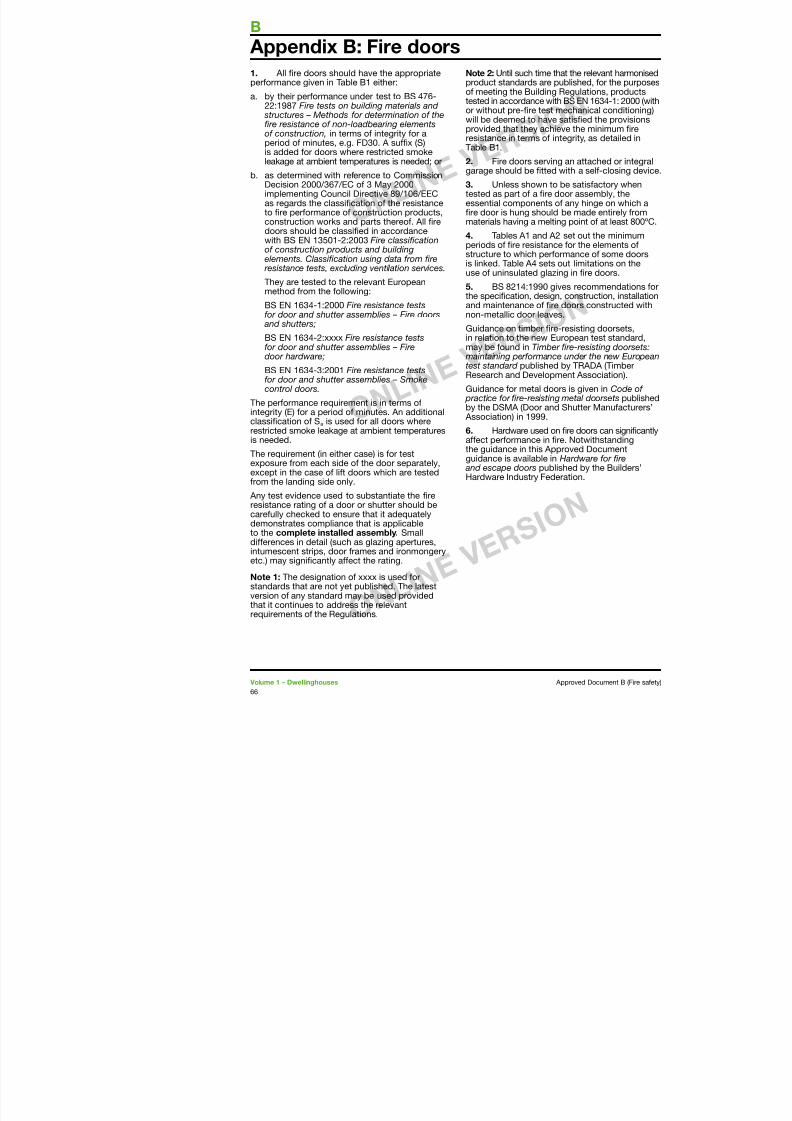
7/29/2019 Bldg_Reg_2006
http://slidepdf.com/reader/full/bldgreg2006 68/86
perormance given in Table B either:
a. by their perormance under test to BS 476-22:987 Fire tests on building materials and structures – Methods or determination o there resistance o non-loadbearing elementso construction, in terms o integrity or aperiod o minutes, e.g. FD30. A sux (S)is added or doors where restricted smokeleakage at ambient temperatures is needed; or
b. as determined with reerence to CommissionDecision 2000/367/EC o 3 May 2000implementing Council Directive 89/06/EECas regards the classication o the resistanceto re perormance o construction products,construction works and parts thereo. All redoors should be classied in accordancewith BS EN 350-2:2003 Fire classicationo construction products and buildingelements. Classication using data rom re resistance tests, excluding ventilation services.
They are tested to the relevant Europeanmethod rom the ollowing:
BS EN 634-:2000 Fire resistance testsor door and shutter assemblies – Fire doors and shutters;
BS EN 634-2:xxxx Fire resistance testsor door and shutter assemblies – Firedoor hardware;
BS EN 634-3:200 Fire resistance testsor door and shutter assemblies – Smokecontrol doors.
The perormance requirement is in terms ointegrity (E) or a period o minutes. An additionalclassication o Sa is used or all doors whererestricted smoke leakage at ambient temperaturesis needed.
The requirement (in either case) is or testexposure rom each side o the door separately,except in the case o lit doors which are testedrom the landing side only.
Any test evidence used to substantiate the rei t ti d h tt h ld b
product standards are publiso meeting the Building Reg
tested in accordance with BSor without pre-re test mechwill be deemed to have satisprovided that they achieve tresistance in terms o integrTable B.
2. Fire doors serving angarage should be tted with
3. Unless shown to be stested as part o a re door essential components o anre door is hung should be materials having a melting p
4. Tables A and A2 setperiods o re resistance orstructure to which perormais linked. Table A4 sets out luse o uninsulated glazing in
5. BS 824:990 gives the specication, design, coand maintenance o re doonon-metallic door leaves.
Guidance on timber re-resin relation to the new Europmay be ound in Timber re maintaining perormance un
test standard published by TResearch and Development
Guidance or metal doors is practice or re-resisting meby the DSMA (Door and Shu Association) in 999.
6. Hardware used on re aect perormance in re. Nthe guidance in this Approvguidance is available in Hard and escape doors publishedHardware Industry Federatio
Table B Provision or ire doors
Position o door Minimum ire resistance o door interms o integrity (minutes) whent t d t BS 476 22 1987 ()
Minimtermst th
FIRE DOORS
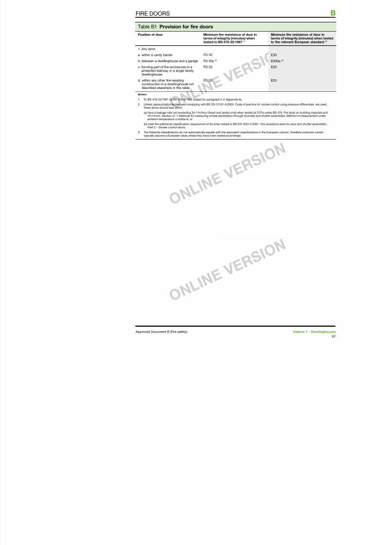
7/29/2019 Bldg_Reg_2006
http://slidepdf.com/reader/full/bldgreg2006 69/86
tested to BS 476-22:1987 () to the
. Any door:a. within a cavity barrier
b. between a dwellinghouse and a garage
c. orming part o the enclosures to aprotected stairway in a single amilydwellinghouse
d. within any other ire-resistingconstruction in a dwellinghouse notdescribed elsewhere in this table
FD 30
FD 30s (2)
FD 20
FD 20
E30
E30Sa
E20
E20
Notes:
. To BS 476-22:987 (or BS 476-8:972 subject to paragraph 5 in Appendix A).
2. Unless pressurization techniques complying with BS EN 20-6:2005Code o practice or smoke controthese doors should also either:
(a) have a leakage rate not exceeding 3m3 /m/hour (head and jambs only) when tested at 25 Pa under BS 4 structures, Section 3. Methods or measuring smoke penetration through doorsets and shutter assem ambient temperature conditions; or
(b) meet the additional classiication requirement o Sa when tested to BS EN 634-3:200Fire resistancePart 3 – Smoke control doors.
3. The National classiications do not automatically equate with the equivalent classiications in the European
typically assume a European class unless they have been tested accordingly.
1. Some orm o measurement is an integralpart o many o the provisions in this document.
B
Appendix C: Methods o measurem
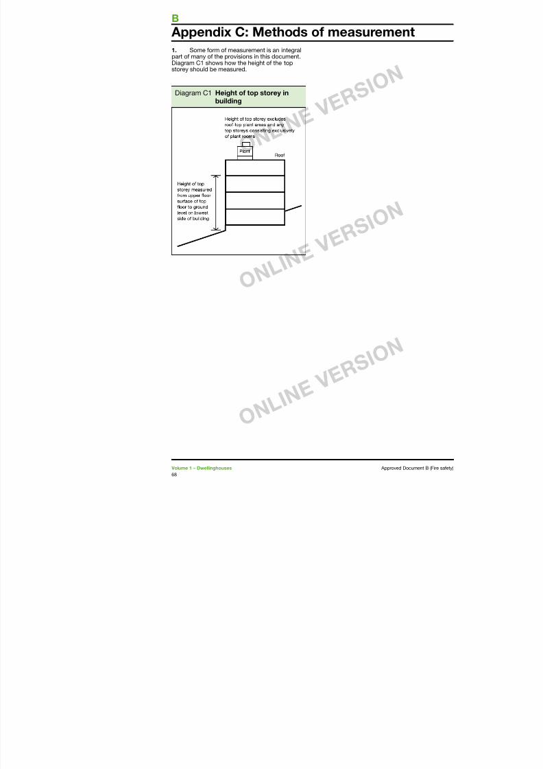
7/29/2019 Bldg_Reg_2006
http://slidepdf.com/reader/full/bldgreg2006 70/86
p y pDiagram C shows how the height o the top
storey should be measured.
Diagram C Height o top storey inbuilding
1. Many o the provisions in this documentare related to the use o the building. The use
2. Table D sets classication.
Appendix D: Purpose groups
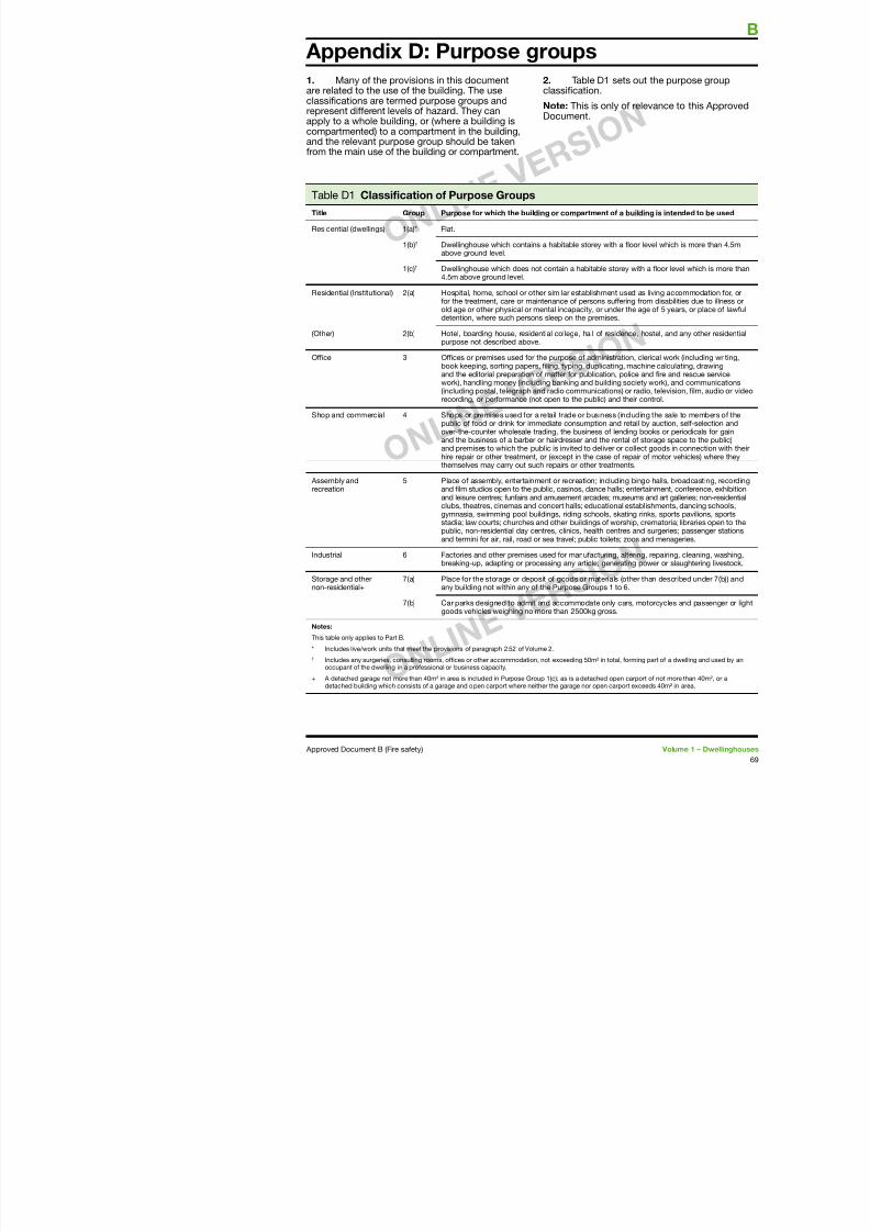
7/29/2019 Bldg_Reg_2006
http://slidepdf.com/reader/full/bldgreg2006 71/86
classications are termed purpose groups and
represent dierent levels o hazard. They canapply to a whole building, or (where a building iscompartmented) to a compartment in the building,and the relevant purpose group should be takenrom the main use o the building or compartment.
Table D Classiication o Purpose Groups
Title Group Purpose or which the building or compartment o a b
Residential (dwellings) (a)* Flat.
(b)† Dwellinghouse which contains a habitable storey with a loabove ground level.
(c)† Dwellinghouse which does not contain a habitable storey 4.5m above ground level.
Residential (Institutional) 2(a) Hospital, home, school or other similar establishment useor the treatment, care or maintenance o persons suerin
old age or other physical or mental incapacity, or under thdetention, where such persons sleep on the premises.
(Other) 2(b) Hotel, boarding house, residential college, hall o residencpurpose not described above.
Oice 3 Oices or premises used or the purpose o administrationbook keeping, sorting papers, iling, typing, duplicating, mand the editorial preparation o matter or publication, poliwork), handling money (including banking and building so(including postal, telegraph and radio communications) orrecording, or perormance (not open to the public) and the
Shop and commercial 4 Shops or premises used or a retail trade or business (inclpublic o ood or drink or immediate consumption and retover-the-counter wholesale trading, the business o lendinand the business o a barber or hairdresser and the rental and premises to which the public is invited to deliver or cohire repair or other treatment, or (except in the case o repthemselves may carry out such repairs or other treatments
Assembly andrecreation
5 Place o assembly, entertainment or recreation; including and ilm studios open to the public, casinos, dance halls; en
and leisure centres; unairs and amusement arcades; museuclubs, theatres, cinemas and concert halls; educational esgymnasia, swimming pool buildings, riding schools, skatinstadia; law courts; churches and other buildings o worshpublic, non-residential day centres, clinics, health centres and termini or air, rail, road or sea travel; public toilets; zo
Note: This is only o
Document.
Note: Except or the items marked * (whichare rom the Building Regulations), thesed iti l l t P t B
Ceiling A part o a building is exposed overhead in a ro
i l ti (Th
B
Appendix E: Deinitions
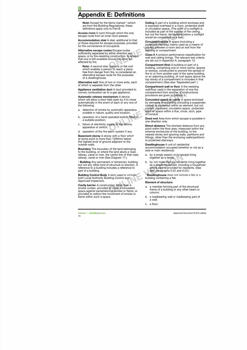
7/29/2019 Bldg_Reg_2006
http://slidepdf.com/reader/full/bldgreg2006 72/86
denitions apply only to Part B.
Access room A room through which the onlyescape route rom an inner room passes.
Accommodation stair A stair, additional to thator those required or escape purposes, providedor the convenience o occupants.
Alternative escape routes Escape routessuciently separated by either direction andspace, or by re-resisting construction, to ensure
that one is still available should the other beaected by re.
Note: A second stair, balcony or fat roowhich enables a person to reach a placeree rom danger rom re, is considered analternative escape route or the purposeso a dwellinghouse.
Alternative exit One o two or more exits, eacho which is separate rom the other.
Appliance ventilation duct A duct provided toconvey combustion air to a gas appliance.
Automatic release mechanism A devicewhich will allow a door held open by it to closeautomatically in the event o each or any one othe ollowing:
a. detection o smoke by automatic apparatussuitable in nature, quality and location;
b. operation o a hand-operated switch tted ina suitable position;
c. ailure o electricity supply to the device,apparatus or switch;
d. operation o the re alarm system i any.
Basement storey A storey with a foor whichat some point is more than 200mm below
the highest level o ground adjacent to theoutside walls.
Boundary The boundary o the land belongingto the building, or where the land abuts a road,railway, canal or river, the centre line o that road,
il l i (S Di 7 )
or circulation space. (The so
included as part o the surabut not the rame. An upstawould be considered as a w
Circulation space A spaceprotected stairway) mainly uaccess between a room andbuilding or compartment.
Class 0 A product perormawall and ceiling linings. The
are set out in Appendix A, p
Compartment (re) A buildbuilding, comprising one or or storeys, constructed to pre to or rom another part or an adjoining building. (A top storey o a compartmencompartment.) (See also ‘Se
Compartment wall or foowall/foor used in the separacompartment rom another.provisions are given in Sect
Concealed space or cavityby elements o a building (inceiling) or contained within a room, cupboard, circulatioshat or space within a fue,
or conduit.Dead end Area rom which one direction only.
Direct distance The shortepoint within the foor area, mexternal enclosures o the bnearest storey exit ignoring ttings, other than the encloto protected stairways.
Dwellinghouse A unit o reaccommodation occupied (sole or main residence):
a. by a single person or byt th il
d. a gallery (but not a loading gallery, fy gallery,stage grid, lighting bridge, or any galleryprovided or similar purposes or ormaintenance and repair);
e an external wall;
Fire-resisting (re ra component or consatisy, or a stated pthe appropriate critepart o BS 476.
DEFINITIONS
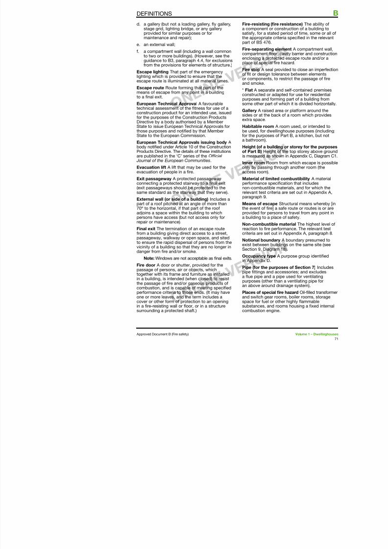
7/29/2019 Bldg_Reg_2006
http://slidepdf.com/reader/full/bldgreg2006 73/86
e. an external wall;
. a compartment wall (including a wall commonto two or more buildings). (However, see theguidance to B3, paragraph 4.4, or exclusionsrom the provisions or elements o structure.)
Escape lighting That part o the emergencylighting which is provided to ensure that theescape route is illuminated at all material times.
Escape route Route orming that part o the
means o escape rom any point in a buildingto a nal exit.
European Technical Approval A avourabletechnical assessment o the tness or use o aconstruction product or an intended use, issuedor the purposes o the Construction ProductsDirective by a body authorised by a MemberState to issue European Technical Approvals orthose purposes and notied by that Member
State to the European Commission.European Technical Approvals issuing body A body notied under Article 0 o the ConstructionProducts Directive. The details o these institutionsare published in the ‘C’ series o the Ocial Journal o the European Communities.
Evacuation lit A lit that may be used or theevacuation o people in a re.
Exit passageway A protected passagewayconnecting a protected stairway to a nal exit(exit passageways should be protected to thesame standard as the stairway that they serve).
External wall (or side o a building) Includes apart o a roo pitched at an angle o more than70º to the horizontal, i that part o the rooadjoins a space within the building to whichpersons have access (but not access only or
repair or maintenance).Final exit The termination o an escape routerom a building giving direct access to a street,passageway, walkway or open space, and sitedto ensure the rapid dispersal o persons rom thei i it b ildi th t th l i
p
Fire-separating elecompartment foor, cenclosing a protecteplace o special re
Fire stop A seal provo t or design toleraor components, to reand smoke.
* Flat A separate and
constructed or adappurposes and orminsome other part o w
Gallery A raised aresides or at the back extra space.
Habitable room A robe used, or dwelling
or the purposes o Pa bathroom).
Height (o a buildingo Part B) Height o is measured as show
Inner room Room ronly by passing throaccess room).
Material o limited cperormance specicnon-combustible marelevant test criteria paragraph 9.
Means o escape Sthe event o re] a saprovided or personsa building to a place
Non-combustible mreaction to re perocriteria are set out in
Notional boundary exist between buildin
Protected circuit An electrical circuit protectedagainst re.
Protected stairway A stair discharging througha nal exit to a place o saety (including any exitpassageway between the oot o the stair and
Storey exit A nal exit, or a access into a protected stalobby or external escape ro
Suspended ceiling (re-prsuspended below a foor w
B DEFINITIONS
7/29/2019 Bldg_Reg_2006
http://slidepdf.com/reader/full/bldgreg2006 74/86
passageway between the oot o the stair and
the nal exit) that is adequately enclosed withre-resisting construction.
Purpose group A classication o a buildingaccording to the purpose to which it is intendedto be put. See Appendix D, Table D.
Relevant boundary The boundary which theside o the building aces, (and/or coincides with)and which is parallel, or at an angle o not morethan 80º, to the side o the building (see Section
9 Diagram 7). A notional boundary can be arelevant boundary.
Roofight A dome light, lantern light, skylight,ridge light, glazed barrel vault or other elementintended to admit daylight through a roo.
Room (or the purposes o B2) An enclosedspace within a building that is not used solely asa circulation space. (The term includes not only
conventional rooms, but also walk-in cupboardsthat are not ttings, and large spaces such aswarehouses and auditoria. The term does notinclude voids such as ducts, ceiling voids androo spaces.)
Sheltered housing Includes:
a. two or more dwellings in the same building;
b. two or more dwellings on adjacent sites
where those dwellings are, in each case, designedand constructed or the purpose o providingresidential accommodation or vulnerable orelderly people who receive, or who are to receive,a support service.
Single-storey building A building consistingo a ground storey only. (A separated part whichconsists o a ground storey only, with a rooto which access is only provided or repair
or maintenance, may be treated as a singlestorey building.) Basements are not includedin counting the number o storeys in a building.
Site (o a building) The land occupied by thebuilding, up to the boundaries with land in other
suspended below a foor, w
the re resistance o the foo A3, classies dierent types
Technical specication A stTechnical Approval Guide. Iagainst which compliance cthe case o a standard and assessment is made to deliTechnical Approval.
Thermoplastic material Se
paragraph 7.
Unprotected area In relatioexternal wall o a building m
a. window, door or other o
Note: Windows that areare designed and glazednecessary level o re rebe regarded as an unpro
b. any part o the external than the relevant re resSection 8.
c. any part o the external combustible material mothick attached or applieace, whether or claddipurpose. Combustible m
context is any material whave a Class 0 rating.)
Standards BS EN ISO 1182:200
Appendix F: Standards and othepublications reerred to

7/29/2019 Bldg_Reg_2006
http://slidepdf.com/reader/full/bldgreg2006 75/86
Standards
DD 252:2002Components or residential sprinklersystems. Specication and test methodsor residential sprinklers
BS EN ISO 306:2004Plastics. Thermoplastic materials. Determinationo Vicat sotening temperature (VST)
BS 476-3:2004
Fire tests on building materials and structures.Classication and method o test or external reexposure to roos
BS 476-4:1970Fire tests on building materials and structures.Non-combustibility test or materials
BS 476-6:1989Fire tests on building materials and structures.
Method o test or re propagation or productsBS 476-7:1997Fire tests on building materials and structures.Method o test to determine the classication othe surace spread o fame o products
BS 476-8:1972Fire tests on building materials and structures.Test methods and criteria or the re resistanceo elements o building construction (withdrawn)
BS 476-11:1982Fire tests on building materials and structures.Method or assessing the heat emission rombuilding materials
BS 476-20:1987Fire tests on building materials and structures.Method or determination o the re resistanceo elements o construction (general principles)
BS 476-21:1987Fire tests on building materials and structures.Methods or determination o the re resistanceo loadbearing elements o construction
BS 476-22:1987
BS EN ISO 1182:200
Reaction to re testsNon-combustibility t
DD ENV 1187:2002Test methods or ext
BS EN ISO 1716:200Reaction to re testsDetermination o the
BS 5438:1989
Methods o test or fabrics when subjectapplied to the ace ooriented specimens
BS 5446-1:2000Fire detection and rSpecication or smo
BS 5446-2:2003Fire detection and rSpecication or hea
BS 5839-1:2002Fire detection and reCode o practice orcommissioning and
BS 5839-6:2004Fire detection and reCode o practice or
maintenance o re dsystems in dwellings
BS 5867-2:1980Specication or abFlammability require
BS 7974:2001 Application o re sato the design o build
BS 9251:2005Sprinkler systems ooccupancies. Code
BS 8214:1990Code o practice or
BS EN 1365-3:2000Fire resistance tests or loadbearingelements. Beams
BS EN 1365-4:1999Fire resistance tests or loadbearing
BS EN 13823:2002Reaction to re tests or buBuilding products excludingto thermal attack by a single
B STANDARDS AND OTHER PUBLICATIONS REFERR
7/29/2019 Bldg_Reg_2006
http://slidepdf.com/reader/full/bldgreg2006 76/86
Fire resistance tests or loadbearing
elements. ColumnsBS EN 1366-1:1999Fire resistance tests or service installations. Ducts
BS EN 1366-2:1999Fire resistance tests or service installations.Fire dampers
BS EN 1366-3:2004Fire resistance tests or service installations.
Penetration sealsBS EN 1366-4:2006Fire resistance tests or service installations.Linear joint seals
BS EN 1366-5:2003Fire resistance tests or service installations.Service ducts and shats
BS EN 1366-6:2004
Fire resistance tests or service installations.Raised access and hollow core foors
BS EN 1634-1:2000Fire resistance tests or door and shutterassemblies. Fire doors and shutters
BS EN 1634-3:2001Fire resistance tests or door and shutterassemblies. Smoke control doors and shutters
BS EN ISO 11925-2:2002Reaction to re tests. Ignitability o buildingproducts subjected to direct impingement ofame. Single-fame source test
BS EN 13238:2001Reaction to re tests or building products.Conditioning procedures and general rules orselection o substrates
BS EN 13501-1:2002
Fire classication o construction products andbuilding elements. Classication using test datarom reaction to re tests
BS EN 13501-2:2003Fire classication o construction products and
PublicationsLegislation
Disability Discrimination Act
Education Act 996
Pipelines Saety Regulation825 and the Gas Saety (InsRegulations 998 SI 998 N
Electromagnetic Compatibi(SI 992 No 2372)
Electromagnetic CompatibiRegulations 994 (SI 994 N
Electrical Equipment (Saety(SI 994 No 3260)
Commission Decision 2000/September 2000 implement89/06/EEC
(European tests) CommissioEC o 3rd May 2000 implemDirective 89/06/EEC
Commission Decision 200/200 implementing Council as regards the classiicationperormance o roos and ro
Commission Decision 2005/November 2005 amending Dregarding the classiication perormance o roos and ro
Commission Decision 2000/February 2000 implementing89/06/EEC
Commission Decision 2000/
2000 implementing Council Commission Decision 96/60996
94/6 /EC implementing ACouncil Directive 89/06/EE
STANDARDS AND OTHER PUBLICATIONS REFERRED
Association or Specialist Fire Protection (ASFP)
ASFP Red book – Fire stopping and penetration seals or the construction industry 2nd EditionISBN: 87040 923 X
ASFP Yellow book Fire protection or structural
Department or Edu
Building Bulletin (BB
www.des.gov.uk
Department o Hea
7/29/2019 Bldg_Reg_2006
http://slidepdf.com/reader/full/bldgreg2006 77/86
ASFP Yellow book – Fire protection or structural
steel in buildings 4th Edition ISBN: 87040 925 6
ASFP Grey book – Fire and smoke resistingdampers ISBN: 87040 924 8
ASFP Blue book – Fire resisting ductwork 2ndEdition ISBN: 87040 926 4
www.asp.org.uk
The British Automatic Sprinkler
Association (BAFSA)Sprinklers or Saety: Use and Beneits o Incorporating Sprinklers in Buildings and Structures, (2006) ISBN: 0 95526 280
www.basa.org.uk
Building Research Establishment Limited (BRE)
BRE Digest 208 I ncreasing the ire resistance
o existing timber loors 988 ISBN: 978 8608 359 7
BRE report (BR 368) Design methodologiesor smoke and heat exhaust ventilation 999ISBN: 978 8608 289 7
BRE report (BR 274) Fire saety o PTFE-based materials used in buildings 994 ISBN: 978 8608 653 6
BRE report (BR 35) Fire perormance o external thermal insulation or walls o multi-storey buildings 2003 ISBN: 978 8608 622 2
BRE report (BR 87) External ire spread:Building separation and boundary distances 99ISBN: 978 8608 465 5
BRE report (BR28) Guidelines or theconstruction o ire resisting structural elements 988 ISBN: 0 8525 293
BRE 454 Multi-storey timber rame buildings – a design guide 2003 ISBN: 8608 605 3
www.bre.co.uk
Builders Hardware Industry Federation
Department o Hea
HTM 05 – 02 Guidan provisions or health
www.dh.gov.uk
Door and Shutter M Association (DSMA
Code o practice or doorsets 999
www.dhonline.org.u
Environment Agenc
Pollution Prevention Managing Fire Water
www.environment-ag
Football Licensing A
Concourses ISBN: 0www.laweb.org.uk/
Fire Protection Ass
Design guide
www.thepa.co.uk
Glass and Glazing F
A guide to best pracuse o ire-resistant g
www.gg.org.uk
Health and Saety E
Workplace health, saThe Workplace (HeaRegulations 992, Aand Guidance; The H
Commission, L24; pISBN: 0 886 333 9
www.hse.gov.uk
International AssocC ( CSC
B STANDARDS AND OTHER PUBLICATIONS REFERR
Steel Construction Institute (SCI)
SCI P197 Designing or structural ire saety: A handbook or architects and engineers 999ISBN: 85942 074 5
SCI Publication 288 Fire sae design: A new
7/29/2019 Bldg_Reg_2006
http://slidepdf.com/reader/full/bldgreg2006 78/86
SCI Publication 288 Fire sae design: A new
approach to multi-storey steel-ramed buildings(Second Edition) 2000 ISBN: 85942 69 5
SCI Publication P313 Single storey steel ramed buildings in ire boundary conditions 2002ISBN: 85942 35 0
www.steel-sci.org
Timber Research and Development Associations (TRADA)
Timber Fire-Resisting Doorsets: maintaining perormance under the new European test standard ISBN: 9005 035 9
www.trada.co.uk
A
Access or re serviceSee Fire service acilities
BathroomsInner rooms 2.9Smoke alarms .7
Beams
C
Ca
Index
7/29/2019 Bldg_Reg_2006
http://slidepdf.com/reader/full/bldgreg2006 79/86
Access panelsFire protecting suspended ceilingsTable A3
Access roomsDenition Appendix EMeans o escape rom innerrooms 2.9
Accommodation stairsDenition Appendix E
AccreditationInstallers and suppliers 0.3–0.5
Adult placements 0.23
Aggregate notional areaSpace separation 9.3
Air changesSee Ventilation
Air circulation systems or heating, etcHouses with a foor more than 4.5m
above ground level 2.6–2.7 Air conditioning
Ducts and integrity ocompartments 7.0
Alarm systemsSee Automatic re detection and
alarm system Alterations
Material alteration 0.20, 2.20Fire alarm and re detection
systems .8 Alternative escape routes B.v
Denition Appendix EHouses with foor more than 4.5m
above ground 2.6, 2.7 Alternative exits
Denition Appendix E
Fire doors Table B Appliance ventilation ducts
Compartments 7.Denition Appendix E
Approved documents page 4 Architraves
Denition o wall and ceiling 3.2, 3.3 Articial lighting
See Lighting Automatic doors
Automatic release mechanismDenition Appendix E
Automatic sel-closing devicesFire doors Appendix B(2)
Automatic re dampersOpenings in cavity barriers 6.8
Automatic re detection and alarmsystem .–.24
Fire resistance 4.2, Table ABoiler roomsSmoke alarms .8
Boundaries 9.4–9.6Denition Appendix ESpace separation or buildings tted
with sprinklers 9.5See also Notional boundaries;
Relevant boundariesBritish Standards pages 73–74
476 Appendix A(2)Part 3 0.4, 0.9, Appendix A(6)
Part 4 B2.v, Appendix A(8), Table A6Part 6 B2.v, Appendix A(2),
Appendix A(5), Appendix A(20)Part 7 B2.v, 0.7, Appendix A(),
Appendix A(5), Appendix A(20)Part 8 Appendix A(5), Table A,
Table BPart B2.v, Appendix A(8–9),
Tables A6–A7Part 22 Appendix B(), Table BParts 20–24 Appendix A(5),
Table A2782 Appendix A(20), Appendix A(2)454 Table 35255 Table 35438 Appendix A(20)5446
Part .4Part 2 .4
5839Part .7, .22, .24Part 6 .3, .4, .6, .7, .0,
.2, .22, .24
5867Part 2 Appendix A(20)
6336 Appendix A(2)7974 0.25824 Appendix B(5)925 0.7, 9.5DD 252 0.7EN 77
Part Table A6EN 87 0.9EN 364 Appendix A(5)EN 365 Appendix A(5)
EN 366 Appendix A(5)EN 634 Appendix A(5), Appendix B()
Part 3 Table BEN 20 Table BEN 3238 Appendix A(7)EN 350
CaCa
Ca
Ce
CECe
CeCir
Cla
Cla
Co
Co
Co
ConstructionJunctions 5.9–5.2, Diagram Openings 5.3–5.4
Denition Appendix EElements o structure B3.iiiFlues Diagram 6Nominal internal diameter o pipes
i h h T bl 3
DwellinghouseDenition Appendix E
E
Electrical wiringConcealed spaces 6.–6.8
Exit passagDenition
ExitsSee Alter
StoreyExternal assExternal esc
Fi i
B INDEX
7/29/2019 Bldg_Reg_2006
http://slidepdf.com/reader/full/bldgreg2006 80/86
passing through Table 3Provision 5.2–5.5Unsuitability o cavity barriers 6.3
Composite productsMaterials o limited combustibility
Appendix A(4)Concealed spaces (cavities) 6.
Cavity walls excluded rom provisionsor cavity barriers Diagram 3
Denition Appendix EFire-resisting ceilings 3.6Interrupting Diagram 2
See also Cavity barriersConduits or cables
Openings in cavity barriers 6.8Openings passing through a
separating element 7.2Construction (Health, Saety and
Welare) Regulations 1996 page 5Courtyards
Means o escape 2.8, Diagram 4Cover moulds
Denition o wall and ceiling 3.3Curtain walls
Elements o structure B3.iiiJunction with compartment foor 5.0
D
Dead endAlternative means o escape B.vDenition Appendix EFire service vehicle access route
specication .5, Diagram 24Direct distances
Denition Appendix EDisabled people 0.9Domestic garages
Construction protecting houses5.4, 5.5, Diagram 0
Fire doors between dwelling andgarage Table BAutomatic sel-closing devices
Appendix B(2)Linings Table Smoke alarms .7
Doors and doorways
Denition o wall and ceiling 3.2, 3.3, 3.9External means o escape 2.8Fire resistance Appendix B(),
Appendix B(5)Fire-resisting construction 2.5Lot conversions 2.20
p
Fire-stopping 7.2–7.4Openings in cavity barriers 0.4Openings passing through a
separating element 7.2Smoke alarms .9–.22
Elements o structureDenition Appendix EFire resistance B3.iii, 4.–4.8, 8.,
Appendix A(5)Tests by element Table A
Emergency egress windowsSee Windows
Enclosed spaceGround or basement storey exits
Diagram 4Enclosing rectangle
Space separation 9.3Enclosure
Drainage or water supply pipesDiagram 5
Environmental protection page 7Escape lighting
Denition Appendix EEscape routes
Denition Appendix EEnclosure o existing stair 2.20Houses with foor more than 4.5m
above ground level 2.5–2.7Use o uninsulated glazed elements
on escape routes Table A4See also Protected escape routes
Escape stairs 2.5External
Fire resistance o adjacent areasDiagram 7
European Standards pages 73–74EN 77
Part Table A6EN 87 0.9EN 364 Appendix A(5)EN 365 Appendix A(5)EN 366 Appendix A(5)EN 634 Appendix A(5), Appendix B()
Part 3 Table BEN 20 Table BEN 3238 Appendix A(7)EN 350
Part B2.v, Appendix A(7)–A(9),Appendix A(), Appendix A(5),Tables A6, A7
Part 2 Appendix A(5), Appendix B()Part 3 Appendix A(5)Part 4 Appendix A(5)
Fire resistDiagra
External reExternal wPerormaRequiremRoo cov
SeparTab
External staFire resist
Diagra
External waConstrucDenitionElementsExternal External Facing a Fire resisJunction
5.9, 5.Unprotec
Diagra
Calcuunp
F
Final exits BDenitionEnclosureHouses w
aboveFire alarms
See alsoand al
Fire damperOpenings
Fire detectioSee Auto
alarm Fire doors A
DenitionSee also
Fire load deFire penetra
Fireplace suDenition
Fire propagInternal li
AppenFire resistan
Fire-separating elements B3.iiiDenition Appendix EFire-stopping 7.2
Fire separationBetween buildings 5., 5.7, 5.8
External walls B4.i, 9.6Garages and houses Diagram 0
Fire resistance B3 ii B3 iii
G
GalleriesCeiling denition 3.3Denition Appendix EFire resistance 4.2Means o escape 2.2, Diagram 5
Garages
I
Ign
Inn
INDEX
7/29/2019 Bldg_Reg_2006
http://slidepdf.com/reader/full/bldgreg2006 81/86
Fire resistance B3.ii, B3.iiiLot conversions 2.20More than one foor over 4.5m above
ground level Diagram 3Openings 7., 7.2
Compartment walls 5.3Separated parts
Compartmentation 5.2–5.5, 5.7, 5.8See also Cavity barriers
Fire service acilitiesAccess to buildings or re-ghting
personnel B.ix, B5.i
Design .4, .5Perormance B5 guidance page 53Requirement B5 page 52Turning acilities .5, Diagram 24Vehicle access .–.5
Access routes and hard-standings.4, .5, Table 8
Fire spreadSee External re spread; Internal
re spreadFire stops 7.2, 7.2–7.4
Denition Appendix E
Junction o compartment wall orcompartment foor with otherwalls 5.9, 5.0
Junction o compartment wall withroo 5., Diagram
Junction with slates, tiles, corrugatedsheeting or similar 6.6
Reinorcing materials 7.3, Table A7Fire suppression
Alternative systems 0.8See also Sprinkler systems
Fire testsFire resistance by element Table AMethods B2.v, Appendix A(2)Purpose Appendix A(2)
FittingsInternal re spread B2.iv
FixingsCavity barriers 6.7
Flame spread See External re spread; Internal
re spreadFlat roos
Means o escape 2.0Notional designations o coverings
Table A5Flats
Conversion to 4.8Floors
C l d 6
GaragesSee Domestic garages
GardensSee Back gardens
Glazed screensUse on escape routes Table A4
GlazingDenition o walls and ceilings 3.2, 3.3In door not part o wall 3.9Fire resistance o doors 2.5Glass and glazing elements on
escape routes Table A4
Limitations on areas o uninsulatedglazing Table A4
Thermoplastic materials 3.9Unwired glass in roofights 0.8
Group homes or mentally impaired/ mentally ill 0.22
GuardingFlat roo orming escape route 2.0
H
Habitable roomsDenition Appendix ELot conversions
Escape rom 2.20Floors 4.7
Means o escape 2.3, 2.4Hammerhead
Fire service vehicle access routespecication .5
HandicappedSee Disabled people
Hard-standings
Fire-ghting vehicles ., .4, .5Hardware
Fire doors Appendix B(3),Appendix B(6)
HazardSee Places o special re hazard; Risk
Health and saety Limitation on requirements page 4
Heat transerInsulation rom high temperatures
B3.ii, Appendix A(5)Radiation
Calculating acceptableunprotected area 9.4
Discounting 9.2Height
Denition Appendix EMethods o measurement
Ins
Ins Ins
Ins
Int
Int
Int
J
Ju
K
Kit
Suspended ceilings 3.8,Appendix A(9), Table 2
ThermoplasticLayout restrictions Diagram 9
Limitations on requirements page 4Limited combustibility
See Materials o limited combustibilityLinings
Openable windowsSee Windows
OpeningsCavity barriers 6.8Compartment walls separating
buildings or occupancies 5.3Protection 7.–7.4See also Doors and doorways;
Houses wabove
Lot convRoofight
materThermop
ceilingUse o sp
B INDEX
7/29/2019 Bldg_Reg_2006
http://slidepdf.com/reader/full/bldgreg2006 82/86
LiningsSee Internal linings
Living roomsPositioning smoke alarms .
Loadbearing capacity Appendix A(5)Resistance to collapse B3.ii
Loadbearing elements o structureSee Elements o structure
Lot conversionsFloors 4.7Means o escape 2.20
MMaintenance
Fire saety 0., 0.3–0.5Smoke alarms .6, .24
Main usePurpose groups Appendix D()
ManagementPremises 0.See also Central alarm monitoring
Mantle shelvesDenition o walls 3.2
Materials and workmanshipIndependent certication schemes
page 4Regulation 7 page 4
Materials o limited combustibility Class 0 Appendix A(3)Composite products Appendix A(4)Denition Appendix EInsulation above re-protecting
suspended ceilings Table A3Junction o compartment wall with
roo 5.2, Diagram Reinorcing materials used or
re-stopping 7.3Roos Table 5Use Appendix A(9), Table A7
Means o escape 2.–2.20, Diagram Compartment walls
Openings 5.3Criteria B.v–B.viDenition Appendix EPerormance B guidance page 2Requirement B page 2
See also Escape routesMeasurement methods Appendix CMechanical ventilation
See Ventilation
N
See also Doors and doorways;Windows
Other residential usePurpose groups Table D
P
PartitionsCavity barriers 6.5See also Walls
PerormanceAccess and acilities or re
service B5 page 53External re spread B4 page 42Internal re spread
Linings B2 page 25Structure B3 page 30
Internal linings B2.v,Appendix A(0)–A(6)
Materials and structures Appendix A()–A(2)
Means o escape B page 3Ratings o some generic materials
and products Table A8Picture rails
Denition o walls and ceilings 3.3Pipes
Cavity barriers 6.8Compartment walls or foors 5.3
Maximum nominal internaldiameter 7.8, Table 3
Denition Appendix ENon-combustible materials Table A6Openings 7.6–7.9, 7.2Penetrating structure Diagram 4
Pitched roosNotional designations o coverings
Table A5Place o saety
Enclosed space Diagram 4Inside building B.v
Places o special re hazardDenition Appendix E
PlasticsRoofights 3.7, 0.4, 0.6, 0.7
Layout restrictions Diagram 9Limitations on extent Table 2
Limitations on use Table 6, Table 7Spacing and size Diagram 23
See also Thermoplastic materialsPolycarbonate sheet
TP(a) rigid and TP(b) Appendix A(20)Porches
Use o sproofig
Use o unon esc
Protective bFlat roo
PublicationEuropeanAdult Pla
RegulaApproved
J Com
stoN Glaz
impCE MarkiCode o p
doorseConstructConstruc
page 4Crown FiEnsuring
protec
External separadistan
Fire protebuildin
Fire saetHSG
Fire stoppor theASFP
Guideline
re-reBRE AGuide to
housinmentaill) peo
Hardwaredoors
Housing RatingGuida
Increasing
existin208 T
Low VoltaNational A
Placemo pra
P ll ti
Purpose groups Appendix DClassication Table DDenition Appendix EFire saety 0.9
PVC sheetTP(a) rigid Appendix A(20)
S
SealsFire resistance 7.2Proprietary seals 7.4
Pipes 7.7Security
Confict with requirements or means
Sta
Sta
INDEX
7/29/2019 Bldg_Reg_2006
http://slidepdf.com/reader/full/bldgreg2006 83/86
QQuantitative techniques
Risk and hazard evaluation 0.28
R
RadiationSee Heat transer
Relevant boundaries 8., 9.4, 9.5,Diagram 7Denition Appendix E
External walls 000mm or more romrelevant boundary 9.2
External walls within 000mm romrelevant boundary 9.
Separation distances or roo 0.5,Table 5
Small residential method 9.6Residential (institutional) purpose
Purpose groups Table DResidential use
Purpose groups Table D
RiskInsurance 0.2Quantitative techniques o
evaluation 0.28Roo coverings
Concealed spaces between insulatedroo sheeting 6.4
External re spread 0.–0.9Separation distances or roos
Table 5Junction o compartment wall with
roo 5., Diagram
Materials o limited combustibilityTable A7
Notional designations Table A5Roofights
Denition Appendix EDenition o ceilings 3.3Fire resistance 3.7Plastic 3.8, 3.0, 0.4, 0.6, 0.7,
Appendix A(9), Table 2, Table 6,Table 7Layout restrictions Diagram 9Limitations on spacing and size
Diagram 23Unwired glass 0.8
Roos 0.2Ceiling denition 3.3Concealed spaces 6.
Between insulated roo
Confict with requirements or meanso escape B.ix
Sel-closing devicesFire doors Appendix B(2)
Sel-supporting sheetsDesignation o pitched roo coverings
Table A5Semi-detached houses
B3 requirement page 29Separation distances 0.5
Separated parts o buildings 5.7, 5.8Separation
See Fire separation; Space separationSeparation distancesBuildings with sprinkler systems 9.5Canopies 9.0, Diagram 2Compartment size 9.3Roos 0.5, Table 5Unprotected areas which may be
disregarded Diagram 20Services
Penetrating cavity barriers 6.7Protection o openings 7.4See also Air conditioning; Ducts;
Pipes; VentilationShats
See Protected shatsSheltered housing 0.24
Central alarm monitoring .9Denition Appendix E
Shop and commercial purpose groupPurpose groups Table D
ShowersInner rooms 2.9Smoke alarms .7
Single-storey buildingsDenition Appendix EFire resistance o elements o
structure 4.3See also Sheltered housing
Site (o a building)Denition Appendix E
SkirtingsDenition o walls 3.2
Slates and tilesDesignation o pitched roo coverings
Table A5
Fire stopping junctions 6.6Sleeping galleries
Means o escape 2.2Sleeving non-combustible pipes 7.9Smoke alarms .2–.22
Denition Appendix EM t i l lt ti 8
Sta
Sto
Sto
Str
Str
Str
Stu
Su
Su
Su
T
Ta
Te
Te
Th
Th
TP(b)Classication o perormance
B2.v, Appendix A(20)Lighting diusers 3.3
Layout restrictions Diagram 9Roofights
Layout restrictions Diagram 9Trap doors
WarningAutomatic re detection and alarm
system .–.24Escape rom building 2.
Water supply pipesEnclosure Diagram 5
WCsInner rooms 2.9
B INDEX
7/29/2019 Bldg_Reg_2006
http://slidepdf.com/reader/full/bldgreg2006 84/86
pCeiling denition 3.3See also Doors and doorways
Travel distance B.vTurning circles
Fire service vehicle access routespecication .5, Table 8
Turntable laddersSee High reach appliances
U
UKASAccredited laboratories Appendix A()Independent certication schemes
page 4Uninsulated glazing
See GlazingUnobstructed openings
Means o escape 2.8Unprotected areas 9.
Areas disregarded in assessingseparation distance Diagram 20
Boundaries 9.4Combustible material as external
surace 9.8, Diagram 9Denition Appendix EExternal wall 000mm or more rom
relevant boundary 9.2Permitted unprotected areas
9.6, 9.7, Diagram 22, Table 4External wall within 000mm o
relevant boundary 9.Fire resistance 9.7Small unprotected areas 9.9,
Diagram 20Unwired glassRoofights 0.8
Utility roomsInner rooms 2.9
V
Vehicle accessSee Fire service acilities
Ventilation ductsAppliances
Compartments 7.Integrity o compartments 7.0Openings in compartment walls
or foorsContaining fues or or appliance
ventilation 7.
Wind loadsElements o structure B3.iii
WindowsDenition o walls and ceilings 3.2, 3.3Emergency egress 2.8
Replacement windows 2.9Replacement 2.9Thermoplastic materials
Appendix A(9)Glazing 3.9
See also Roofights
WiringSee Electrical wiringWorkmanship and materials
Independent certication schemespage 4
Regulation 7 page 4Workplace (Health, Saety and
Welare) Regulations 1992 page 5
APPROVED DOCUMENTS
The following documents have been approvedand issued by the First Secretary of State forthe purpose of providing practical guidancewith respect to the requirements of the BuildingRegulations 2000 (as amended).
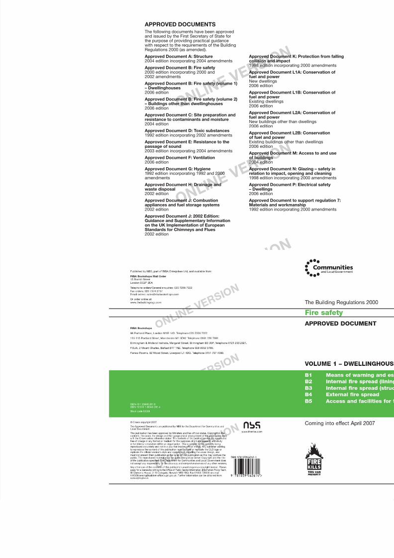
7/29/2019 Bldg_Reg_2006
http://slidepdf.com/reader/full/bldgreg2006 85/86
Approved Document A: Structure2004 edition incorporating 2004 amendments
Approved Document B: Fire safety 2000 edition incorporating 2000 and2002 amendments
Approved Document B: Fire safety (volume 1)– Dwellinghouses2006 edition
Approved Document B: Fire safety (volume 2)– Buildings other than dwellinghouses2006 edition
Approved Document C: Site preparation andresistance to contaminants and moisture2004 edition
Approved Document D: Toxic substances1992 edition incorporating 2002 amendments
Approved Document E: Resistance to thepassage of sound2003 edition incorporating 2004 amendments
Approved Document F: Ventilation2006 edition
Approved Document G: Hygiene1992 edition incorporating 1992 and 2000amendments
Approved Document H: Drainage andwaste disposal2002 edition
Approved Document J: Combustionappliances and fuel storage systems2002 edition
Approved Document J: 2002 Edition:Guidance and Supplementary Informationon the UK Implementation of European
Standards for Chimneys and Flues2002 edition
Approved Documecollision and impa1998 edition incorp
Approved Documefuel and powerNew dwellings2006 edition
Approved Docume
fuel and powerExisting dwellings2006 edition
Approved Documefuel and powerNew buildings othe2006 edition
Approved Documeof fuel and power
Existing buildings o2006 edition
Approved Documeof buildings2004 edition
Approved Documerelation to impact,1998 edition incorp
Approved Docume– Dwellings2006 edition
Approved DocumeMaterials and wor1992 edition incorp

7/29/2019 Bldg_Reg_2006
http://slidepdf.com/reader/full/bldgreg2006 86/86


