Embed Size (px)
Citation preview

Project Manual
BLATT NATATORIUM ENTRANCE UPGRADES
University of South Carolina Columbia, SC
January 6, 2017
Project No. H27-Z293Architect’s Project No. U424.16

Blatt Natatorium Entrance Upgrades H27-Z293 University of South Carolina
PROJECT DIRECTORY 1
PROJECT DIRECTORY
OWNER University of South Carolina Facilities Planning & Construction 743 Greene Street Columbia, SC 29208 (803)777-3126 FAX (803)777-8739
ARCHITECT OF RECORD Garvin Design Group, Inc. 1209 Lincoln Street (29201) P.O. Box 18 Columbia, SC 29202 (803)212-1032 FAX (803)212-1074
PROJECT CONSULTANTS
CIVIL ENGINEER RB Todd Consulting Engineers 7436 Broad River Road. Suite 212 Irmo, SC 29063 (803)781-3141 FAX (803)781-3142
ELECTRICAL ENGINEER Belka Engineering Associates 7 Clusters Court Suite 201 Columbia, SC 29210 (803)731-0650 FAX (803)731-2880

Blatt Natatorium Entrance Upgrades H27-Z293 University of South Carolina
TABLE OF CONTENTS
TABLE OF CONTENTS
PROJECT NUMBER H27-Z293
DIVISION 00 – BIDDING AND CONTRACT REQUIREMENTS
Section Number of Pages
Cover Page 1Project Directory 1Table of Contents 2SE-310, Invitation for Construction Services 1AIA A701 – 1997 Instructions to Bidders – South Carolina Division of Procurement
Services, Office of State Engineer Version 13 Bid Bond (AIA A310) 1SE-330, Lump Sum Bid Form 6AIA Document A101-2007 Standard Form of Agreement between Owner and
Contractor – South Carolina Division of Procurement Services, Office of the State Engineer 9
AIA Document A201-2007 General Conditions of the Contract for Construction – South Carolina Division of Procurement Services, Office of the State Engineer 49
SE-355, Performance Bond 2SE-357, Labor & Material Payment Bond 2SE-380, Change Order to Construction Contract 1 USC Supplemental General Conditions for Construction Projects 5 Contractors One Year Guarantee 1
DIVISION 1 – GENERAL REQUIREMENTS
Section No. Section Title Number of Pages
010000 Special Conditions and Requirements 2 010100 Index to Drawings 1 011000 Summary 3012600 Contract Modification Procedures 2 012900 Payment Procedures 4013100 Project Management and Coordination 8 013200 Construction Progress Documentation 9 013300 Submittal Procedures 9014000 Quality Requirements 7014100 Special Inspections and Testing 9 014200 References 17 015000 Temporary Facilities and Controls 3 016000 Product Requirements 1017000 Execution Requirements 7017700 Closeout Procedures 5017820 Operation and Maintenance Data 7 017830 Project Record Documents 3

Blatt Natatorium Entrance Upgrades H27-Z293 University of South Carolina
TABLE OF CONTENTS
017900 Demonstration Training 5
DIVISION 2 – EXISTING CONDITIONS
024119 Selective Demolition 5
DIVISION 31 – EARTHWORK
311000 Site Clearing 6312000 Earth moving 12 321216 Asphalt Paving 8321313 Concrete Paving 13 328400 Underground Irrigation System 8329000 Landscape Planting 16
END TABLE OF CONTENTS
SE-310
2016 Edition
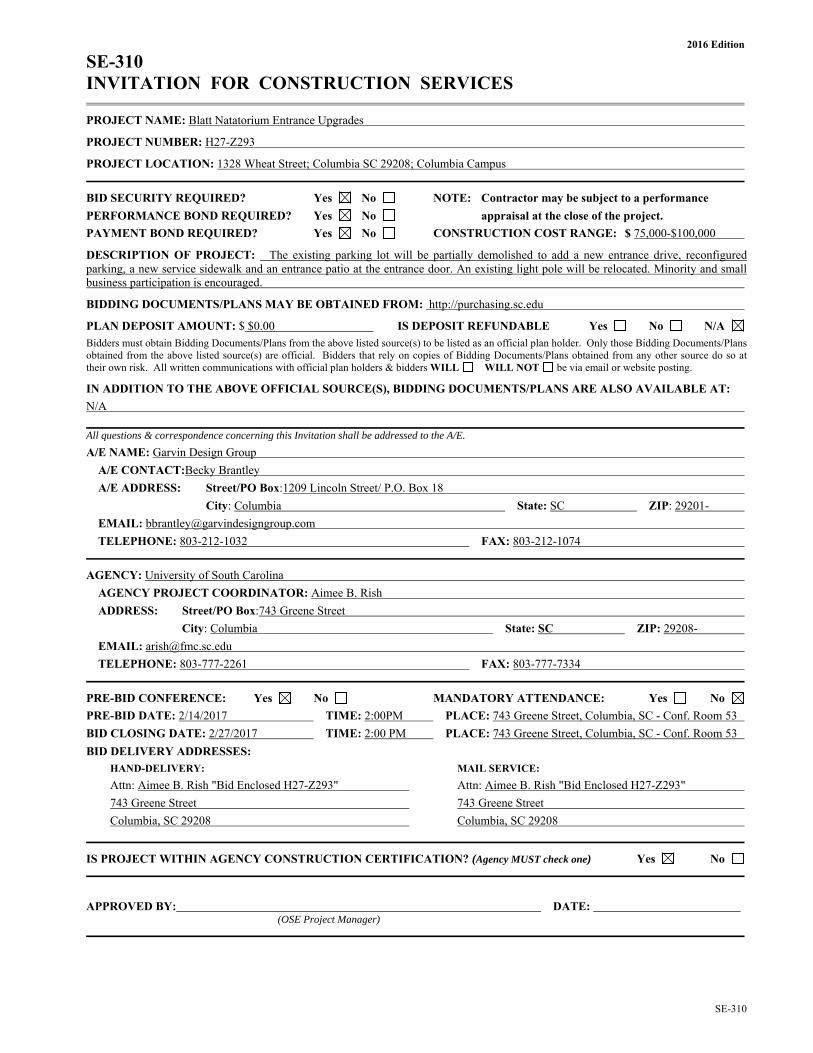
SE-310 INVITATION FOR CONSTRUCTION SERVICES
PROJECT NAME: Blatt Natatorium Entrance Upgrades
PROJECT NUMBER: H27-Z293
PROJECT LOCATION: 1328 Wheat Street; Columbia SC 29208; Columbia Campus
BID SECURITY REQUIRED? Yes No NOTE: Contractor may be subject to a performance
PERFORMANCE BOND REQUIRED? Yes No appraisal at the close of the project.
PAYMENT BOND REQUIRED? Yes No CONSTRUCTION COST RANGE: $ 75,000-$100,000
DESCRIPTION OF PROJECT: The existing parking lot will be partially demolished to add a new entrance drive, reconfigured parking, a new service sidewalk and an entrance patio at the entrance door. An existing light pole will be relocated. Minority and small business participation is encouraged.
BIDDING DOCUMENTS/PLANS MAY BE OBTAINED FROM: http://purchasing.sc.edu
PLAN DEPOSIT AMOUNT: $ $0.00 IS DEPOSIT REFUNDABLE Yes No N/A
Bidders must obtain Bidding Documents/Plans from the above listed source(s) to be listed as an official plan holder. Only those Bidding Documents/Plans obtained from the above listed source(s) are official. Bidders that rely on copies of Bidding Documents/Plans obtained from any other source do so at their own risk. All written communications with official plan holders & bidders WILL WILL NOT be via email or website posting.
IN ADDITION TO THE ABOVE OFFICIAL SOURCE(S), BIDDING DOCUMENTS/PLANS ARE ALSO AVAILABLE AT:
N/A
All questions & correspondence concerning this Invitation shall be addressed to the A/E.
A/E NAME: Garvin Design Group
A/E CONTACT:Becky Brantley
A/E ADDRESS: Street/PO Box:1209 Lincoln Street/ P.O. Box 18
City: Columbia State: SC ZIP: 29201-
EMAIL: [email protected]
TELEPHONE: 803-212-1032 FAX: 803-212-1074
AGENCY: University of South Carolina
AGENCY PROJECT COORDINATOR: Aimee B. Rish
ADDRESS: Street/PO Box:743 Greene Street
City: Columbia State: SC ZIP: 29208-
EMAIL: [email protected]
TELEPHONE: 803-777-2261 FAX: 803-777-7334
PRE-BID CONFERENCE: Yes No MANDATORY ATTENDANCE: Yes No
PRE-BID DATE: 2/14/2017 TIME: 2:00PM PLACE: 743 Greene Street, Columbia, SC - Conf. Room 53
BID CLOSING DATE: 2/27/2017 TIME: 2:00 PM PLACE: 743 Greene Street, Columbia, SC - Conf. Room 53
BID DELIVERY ADDRESSES:
HAND-DELIVERY: MAIL SERVICE:
Attn: Aimee B. Rish "Bid Enclosed H27-Z293" Attn: Aimee B. Rish "Bid Enclosed H27-Z293"
743 Greene Street 743 Greene Street
Columbia, SC 29208 Columbia, SC 29208
IS PROJECT WITHIN AGENCY CONSTRUCTION CERTIFICATION? (Agency MUST check one) Yes No
APPROVED BY: DATE: (OSE Project Manager)


BF – 1 SE-330
2016 Edition
SE-330 LUMP SUM BID FORM Bidders shall submit bids on only Bid Form SE-330.
BID SUBMITTED BY: (Bidder's Name)
BID SUBMITTED TO: University of South Carolina (Owner’s Name)
FOR: PROJECT NAME: Blatt Natatorium Entrance Upgrades
PROJECT NUMBER: H27-Z293
OFFER
§ 1. In response to the Invitation for Construction Services and in compliance with the Instructions to Bidders for the above-named Project, the undersigned Bidder proposes and agrees, if this Bid is accepted, to enter into a Contract with the Owner on the terms included in the Bidding Documents, and to perform all Work as specified or indicated in the Bidding Documents, for the prices and within the time frames indicated in this Bid and in accordance with the other terms and conditions of the Bidding Documents.
§ 2. Pursuant to Section 11-35-3030(1) of the SC Code of Laws, as amended, Bidder has submitted Bid Security as follows in the amount and form required by the Bidding Documents:
Bid Bond with Power of Attorney Electronic Bid Bond Cashier's Check (Bidder check one)
§ 3. Bidder acknowledges the receipt of the following Addenda to the Bidding Documents and has incorporated the effects of said Addenda into this Bid: (Bidder, check all that apply. Note, there may be more boxes than actual addenda. Do not check boxes that do not apply)
ADDENDA: #1 #2 #3 #4 #5
§ 4. Bidder accepts all terms and conditions of the Invitation for Bids, including, without limitation, those dealing with the disposition of Bid Security. Bidder agrees that this Bid, including all Bid Alternates, if any, may not be revoked or withdrawn after the opening of bids, and shall remain open for acceptance for a period of 60 Days following the Bid Date, or for such longer period of time that Bidder may agree to in writing upon request of the Owner.
§ 5. Bidder herewith offers to provide all labor, materials, equipment, tools of trades and labor, accessories, appliances, warranties and guarantees, and to pay all royalties, fees, permits, licenses and applicable taxes necessary to complete the following items of construction work:
§ 6.1 BASE BID WORK (as indicated in the Bidding Documents and generally described as follows): The existing parking lot will be partially demolished to add a new entrance drive, reconfigured parking, a new service sidewalk and an entrance patio at the entrance door. An existing light pole will be relocated.
$ , which sum is hereafter called the Base Bid. (Bidder to insert Base Bid Amount on line above)

BF 3 SE-330
2016 Edition
SE-330 LUMP SUM BID FORM
§ 8. LIST OF MANUFACTURERS, MATERIAL SUPPLIERS, AND SUBCONTRACTORS OTHER THAN SUBCONTRACTORS LISTED IN SECTION 7 ABOVE (FOR INFORMATION ONLY):
Pursuant to instructions in the Invitation for Construction Services, if any, Bidder will provide to Owner upon the Owner’s request and within 24 hours of such request, a listing of manufacturers, material suppliers, and subcontractors, other than those listed in Section 7 above, that Bidder intends to use on the project. Bidder acknowledges and agrees that this list is provided for purposes of determining responsibility and not pursuant to the subcontractor listing requirements of SC Code Ann § 11-35-3020(b)(i).
§ 9. TIME OF CONTRACT PERFORMANCE AND LIQUIDATED DAMAGES
a) CONTRACT TIME
Bidder agrees that the Date of Commencement of the Work shall be established in a Notice to Proceed to be issued by the Owner. Bidder agrees to substantially complete the Work within 60 Calendar Days from the Date of Commencement, subject to adjustments as provided in the Contract Documents.
b) LIQUIDATED DAMAGES
Bidder further agrees that from the compensation to be paid, the Owner shall retain as Liquidated Damages the amount of $ 250.00 for each Calendar Day the actual construction time required to achieve Substantial Completion exceeds the specified or adjusted time for Substantial Completion as provided in the Contract Documents. This amount is intended by the parties as the predetermined measure of compensation for actual damages, not as a penalty for nonperformance.
§ 10. AGREEMENTS
a) Bidder agrees that this bid is subject to the requirements of the laws of the State of South Carolina.
b) Bidder agrees that at any time prior to the issuance of the Notice to Proceed for this Project, this Project may be canceled for the convenience of, and without cost to, the State.
c) Bidder agrees that neither the State of South Carolina nor any of its agencies, employees or agents shall be responsible for any bid preparation costs, or any costs or charges of any type, should all bids be rejected or the Project canceled for any reason prior to the issuance of the Notice to Proceed.
§ 11. ELECTRONIC BID BOND
By signing below, the Principal is affirming that the identified electronic bid bond has been executed and that the Principal and Surety are firmly bound unto the State of South Carolina under the terms and conditions of the AIA Document A310, Bid Bond, included in the Bidding Documents. ELECTRONIC BID BOND NUMBER:
SIGNATURE AND TITLE:

BF 4 SE-330
2016 Edition
SE-330 LUMP SUM BID FORM
CONTRACTOR'S CLASSIFICATIONS AND SUBCLASSIFICATIONS WITH LIMITATION
SC Contractor's License Number(s):
Classification(s) & Limits:
Subclassification(s) & Limits: By signing this Bid, the person signing reaffirms all representation and certification made by both the person signing and the Bidder, including without limitation, those appearing in Article 2 of the Instructions to Bidders, is expressly incorporated by reference.
BIDDER’S LEGAL NAME:
ADDRESS:
TELEPHONE:
EMAIL:
SIGNATURE: DATE:
PRINT NAME:
TITLE:


1 of 2 SE-355
2016 Edition
SE-355 PERFORMANCE BOND KNOW ALL MEN BY THESE PRESENTS, that (Insert full name or legal title and address of Contractor)
Name:
Address:
hereinafter referred to as “Contractor”, and (Insert full name and address of principal place of business of Surety) Name:
Address:
hereinafter called the “surety”, are jointly and severally held and firmly bound unto (Insert full name and address of Agency) Name: University of South Carolina
Address: 743 Greene Street Columbia, South Carolina 29208
hereinafter referred to as “Agency”, or its successors or assigns, the sum of ($ ), being the sum of the Bond to which payment to be well and truly made, the Contractor and Surety bind themselves, their heirs, executors, administrators, successors and assigns, jointly and severally, firmly by these presents. WHEREAS, Contractor has by written agreement dated entered into a contract with Agency to construct
State Project Name: Blatt Natatorium Entrance Upgrades State Project Number: H27-Z293 Brief Description of Awarded Work, as found on the SE-330 or SE-332, Bid Form: The existing parking lot will be partially demolished to add a new entrance drive, reconfigured parking, a new service sidewalk and an entrance patio at the entrance door. An existing light pole will be relocated.
in accordance with Drawings and Specifications prepared by (Insert full name and address of A/E) Name: Garvin Design Group
Address: 1209 Lincoln Street Columbia, SC 29201
which agreement is by reference made a part hereof, and is hereinafter referred to as the Contract. IN WITNESS WHEREOF, Surety and Contractor, intending to be legally bound hereby, subject to the terms stated herein, do each cause this Performance Bond to be duly executed on its behalf by its authorized officer, agent or representative. DATED this day of , 2 BOND NUMBER (shall be no earlier than Date of Contract)
CONTRACTOR SURETY By:
(Seal)
By:
(Seal) Print Name:
Print Name:
Print Title:
Print Title: (Attach Power of Attorney)
Witness:
Witness:
(Additional Signatures, if any, appear on attached page)
2 of 2 SE-355
2016 Edition
SE-355 PERFORMANCE BOND
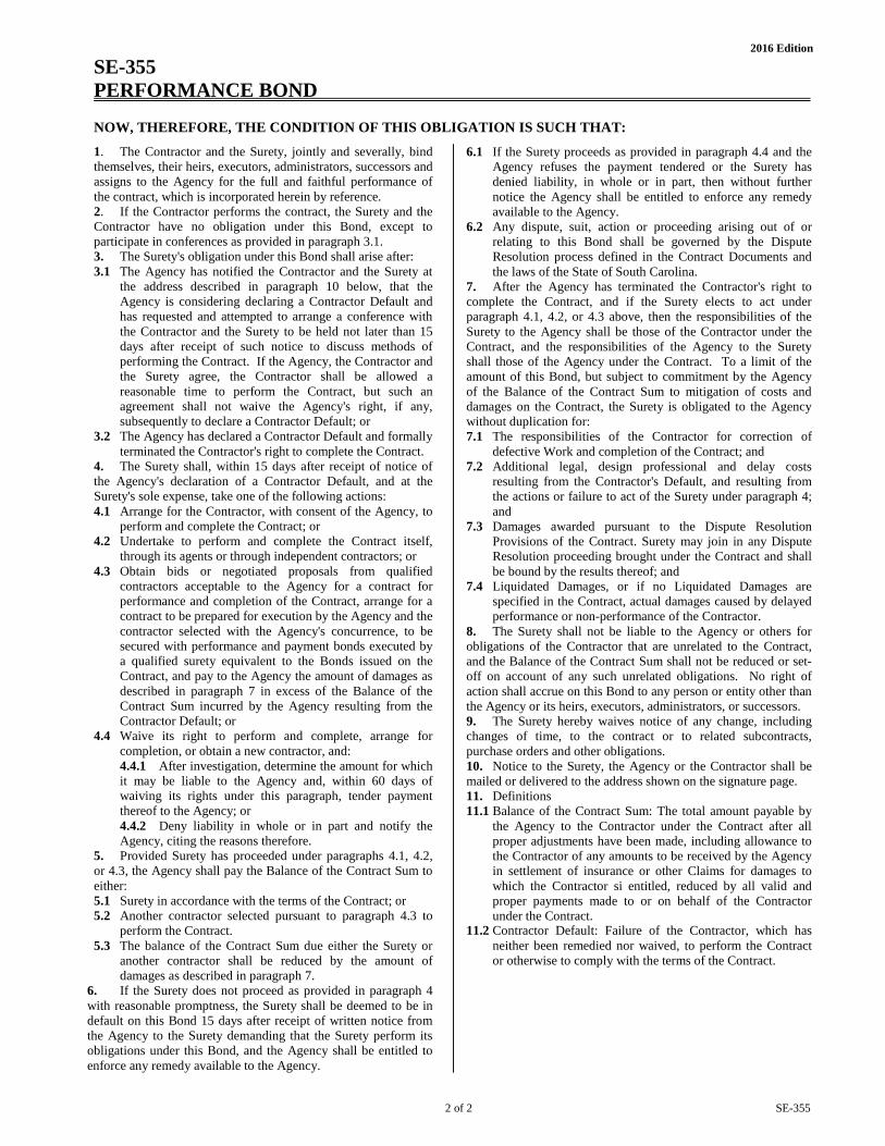
NOW, THEREFORE, THE CONDITION OF THIS OBLIGATION IS SUCH THAT: 1. The Contractor and the Surety, jointly and severally, bindthemselves, their heirs, executors, administrators, successors andassigns to the Agency for the full and faithful performance ofthe contract, which is incorporated herein by reference.2. If the Contractor performs the contract, the Surety and theContractor have no obligation under this Bond, except toparticipate in conferences as provided in paragraph 3.1.3. The Surety's obligation under this Bond shall arise after:3.1 The Agency has notified the Contractor and the Surety at
the address described in paragraph 10 below, that the Agency is considering declaring a Contractor Default and has requested and attempted to arrange a conference with the Contractor and the Surety to be held not later than 15 days after receipt of such notice to discuss methods of performing the Contract. If the Agency, the Contractor and the Surety agree, the Contractor shall be allowed a reasonable time to perform the Contract, but such an agreement shall not waive the Agency's right, if any, subsequently to declare a Contractor Default; or
3.2 The Agency has declared a Contractor Default and formally terminated the Contractor's right to complete the Contract.
4. The Surety shall, within 15 days after receipt of notice ofthe Agency's declaration of a Contractor Default, and at theSurety's sole expense, take one of the following actions:4.1 Arrange for the Contractor, with consent of the Agency, to
perform and complete the Contract; or 4.2 Undertake to perform and complete the Contract itself,
through its agents or through independent contractors; or 4.3 Obtain bids or negotiated proposals from qualified
contractors acceptable to the Agency for a contract for performance and completion of the Contract, arrange for a contract to be prepared for execution by the Agency and the contractor selected with the Agency's concurrence, to be secured with performance and payment bonds executed by a qualified surety equivalent to the Bonds issued on the Contract, and pay to the Agency the amount of damages as described in paragraph 7 in excess of the Balance of the Contract Sum incurred by the Agency resulting from the Contractor Default; or
4.4 Waive its right to perform and complete, arrange for completion, or obtain a new contractor, and: 4.4.1 After investigation, determine the amount for which it may be liable to the Agency and, within 60 days of waiving its rights under this paragraph, tender payment thereof to the Agency; or 4.4.2 Deny liability in whole or in part and notify the Agency, citing the reasons therefore.
5. Provided Surety has proceeded under paragraphs 4.1, 4.2,or 4.3, the Agency shall pay the Balance of the Contract Sum toeither:5.1 Surety in accordance with the terms of the Contract; or5.2 Another contractor selected pursuant to paragraph 4.3 to
perform the Contract. 5.3 The balance of the Contract Sum due either the Surety or
another contractor shall be reduced by the amount of damages as described in paragraph 7.
6. If the Surety does not proceed as provided in paragraph 4with reasonable promptness, the Surety shall be deemed to be indefault on this Bond 15 days after receipt of written notice fromthe Agency to the Surety demanding that the Surety perform itsobligations under this Bond, and the Agency shall be entitled toenforce any remedy available to the Agency.
6.1 If the Surety proceeds as provided in paragraph 4.4 and the Agency refuses the payment tendered or the Surety has denied liability, in whole or in part, then without further notice the Agency shall be entitled to enforce any remedy available to the Agency.
6.2 Any dispute, suit, action or proceeding arising out of or relating to this Bond shall be governed by the Dispute Resolution process defined in the Contract Documents and the laws of the State of South Carolina.
7. After the Agency has terminated the Contractor's right tocomplete the Contract, and if the Surety elects to act underparagraph 4.1, 4.2, or 4.3 above, then the responsibilities of theSurety to the Agency shall be those of the Contractor under theContract, and the responsibilities of the Agency to the Suretyshall those of the Agency under the Contract. To a limit of theamount of this Bond, but subject to commitment by the Agencyof the Balance of the Contract Sum to mitigation of costs anddamages on the Contract, the Surety is obligated to the Agencywithout duplication for:7.1 The responsibilities of the Contractor for correction of
defective Work and completion of the Contract; and 7.2 Additional legal, design professional and delay costs
resulting from the Contractor's Default, and resulting from the actions or failure to act of the Surety under paragraph 4; and
7.3 Damages awarded pursuant to the Dispute Resolution Provisions of the Contract. Surety may join in any Dispute Resolution proceeding brought under the Contract and shall be bound by the results thereof; and
7.4 Liquidated Damages, or if no Liquidated Damages are specified in the Contract, actual damages caused by delayed performance or non-performance of the Contractor.
8. The Surety shall not be liable to the Agency or others forobligations of the Contractor that are unrelated to the Contract,and the Balance of the Contract Sum shall not be reduced or set-off on account of any such unrelated obligations. No right ofaction shall accrue on this Bond to any person or entity other thanthe Agency or its heirs, executors, administrators, or successors.9. The Surety hereby waives notice of any change, includingchanges of time, to the contract or to related subcontracts,purchase orders and other obligations.10. Notice to the Surety, the Agency or the Contractor shall bemailed or delivered to the address shown on the signature page.11. Definitions11.1 Balance of the Contract Sum: The total amount payable by
the Agency to the Contractor under the Contract after all proper adjustments have been made, including allowance to the Contractor of any amounts to be received by the Agency in settlement of insurance or other Claims for damages to which the Contractor si entitled, reduced by all valid and proper payments made to or on behalf of the Contractor under the Contract.
11.2 Contractor Default: Failure of the Contractor, which has neither been remedied nor waived, to perform the Contract or otherwise to comply with the terms of the Contract.
1 of 2 SE-357
2016 Edition
SE-357 LABOR & MATERIAL PAYMENT BOND KNOW ALL MEN BY THESE PRESENTS, that (Insert full name or legal title and address of Contractor)
Name: Address:
hereinafter referred to as “Contractor”, and (Insert full name and address of principal place of business of Surety) Name: Address:
hereinafter called the “surety”, are jointly and severally held and firmly bound unto (Insert full name and address of Agency) Name: University of South Carolina Address: 743 Greene Street
Columbia, SC 29208 hereinafter referred to as “Agency”, or its successors or assigns, the sum of ($ ), being the sum of the Bond to which payment to be well and truly made, the Contractor and Surety bind themselves, their heirs, executors, administrators, successors and assigns, jointly and severally, firmly by these presents.
WHEREAS, Contractor has by written agreement dated entered into a contract with Agency to construct State Project Name: Blatt Natatorium Entrance Upgrades State Project Number: H27-Z293 Brief Description of Awarded Work, as found on the SE-330 or SE-332, Bid Form: The existing parking lot will be partially demolished to add a new entrance drive, reconfigured parking, a new service sidewalk and an entrance patio at the entrance door. An existing light pole will be relocated..
in accordance with Drawings and Specifications prepared by (Insert full name and address of A/E) Name: Garvin Design Group Address: 1209 Lincoln Street
Columbia, SC 29201 which agreement is by reference made a part hereof, and is hereinafter referred to as the Contract.
IN WITNESS WHEREOF, Surety and Contractor, intending to be legally bound hereby, subject to the terms stated herein, do each cause this Labor & Material Payment Bond to be duly executed on its behalf by its authorized officer, agent or representative.
DATED this day of , 2 BOND NUMBER (shall be no earlier than Date of Contract)
CONTRACTOR SURETY
By: (Seal)
By: (Seal)
Print Name: Print Name:
Print Title: Print Title: (Attach Power of Attorney)
Witness: Witness:
(Additional Signatures, if any, appear on attached page)

2 of 2 SE-357
2016 Edition
SE-357 LABOR & MATERIAL PAYMENT BOND NOW, THEREFORE, THE CONDITION OF THIS OBLIGATION IS SUCH THAT: 1. The Contractor and the Surety, jointly and severally, bind themselves, their heirs, executors, administrators, successors and assigns to the Agency to pay for all labor, materials and equipment required for use in the performance of the Contract, which is incorporated herein by reference. 2. With respect to the Agency, this obligation shall be null and void if the Contractor: 2.1 Promptly makes payment, directly or indirectly, for all sums
due Claimants; and 2.2 Defends, indemnifies and holds harmless the Agency from
all claims, demands, liens or suits by any person or entity who furnished labor, materials or equipment for use in the performance of the Contract.
3. With respect to Claimants, this obligation shall be null and void if the Contractor promptly makes payment, directly or indirectly, for all sums due. 4. With respect to Claimants, and subject to the provisions of Title 29, Chapter 5 and the provisions of §11-35-3030(2)(c) of the SC Code of Laws, as amended, the Surety’s obligation under this Bond shall arise as follows: 4.1 Every person who has furnished labor, material or rental
equipment to the Contractor or its subcontractors for the work specified in the Contract, and who has not been paid in full therefore before the expiration of a period of ninety (90) days after the date on which the last of the labor was done or performed by him or material or rental equipment was furnished or supplied by him for which such claim is made, shall have the right to sue on the payment bond for the amount, or the balance thereof, unpaid at the time of institution of such suit and to prosecute such action for the sum or sums justly due him.
4.2 A remote claimant shall have a right of action on the payment bond upon giving written notice by certified or registered mail to the Contractor within ninety (90) days from the date on which such person did or performed the last of the labor or furnished or supplied the last of the material or rental equipment upon which such claim is made.
4.3 Every suit instituted upon a payment bond shall be brought in a court of competent jurisdiction for the county or circuit in which the construction contract was to be performed, but no such suit shall be commenced after the expiration of o ne year after the day on which the last of the labor was performed or material or rental equipment was supplied by the person bringing suit.
5. When the Claimant has satisfied the conditions of paragraph 4, the Surety shall promptly and at the Surety’s expense take the following actions: 5.1 Send an answer to the Claimant, with a copy to the Agency,
within sixty (60) days after receipt of the claim, stating the amounts that are undisputed and the basis for challenging any amounts that are disputed.
5.2 Pay or arrange for payment of any undisputed amounts. 5.3 The Surety’s failure to discharge its obligations under this
paragraph 5 shall not be deemed to constitute a waiver of defenses the Surety or Contractor may have or acquire as to a claim. However, if the Surety fails to discharge its obligations under this paragraph 5, the Surety shall indemnify the Claimant for the reasonable attorney’s fees the Claimant incurs to recover any sums found to be due and owing to the Claimant.
6. Amounts owed by the Agency to the Contractor under the Contract shall be used for the performance of the Contract and to satisfy claims, if any, under any Performance Bond. By the Contractor furnishing and the Agency accepting this Bond, they agree that all funds earned by the contractor in the performance of the Contract are dedicated to satisfy obligations of the Contractor and the Surety under this Bond, subject to the Agency’s prior right to use the funds for the completion of the Work. 7. The Surety shall not be liable to the Agency, Claimants or others for obligations of the Contractor that are unrelated to the Contract. The Agency shall not be liable for payment of any costs or expenses of any claimant under this bond, and shall have under this Bond no obligations to make payments to, give notices on behalf of, or otherwise have obligations to Claimants under this Bond. 8. The Surety hereby waives notice of any change, including changes of time, to the Contract or to related Subcontracts, purchase orders and other obligations. 9. Notice to the Surety, the Agency or the Contractor shall be mailed or delivered to the addresses shown on the signature page. Actual receipt of notice by Surety, the Agency or the contractor, however accomplished, shall be sufficient compliance as of the date received at the address shown on the signature page. 10. By the Contractor furnishing and the Agency accepting this Bond, they agree that this Bond has been furnished to comply with the statutory requirements of the South Carolina Code of Laws, as amended, and further, that any provision in this Bond conflicting with said statutory requirements shall be deemed deleted herefrom and provisions conforming to such statutory or other legal requirement shall be deemed incorporated herein. The intent is that this Bond shall be construed as a statutory Bond and not as a common law bond. 11. Upon request of any person or entity appearing to be a potential beneficiary of this bond, the Contractor shall promptly furnish a copy of this Bond or shall permit a copy to be made. 12. Any dispute, suit, action or proceeding arising out of or relating to this Bond shall be governed by the laws of the State of South Carolina. 13. DEFINITIONS 13.1 Claimant: An individual or entity having a direct contract
with the Contractor or with a Subcontractor of the Contractor to furnish labor, materials, or equipment for use in the performance of the Contract. The intent of this Bond shall be to include without limitation in the terms “labor, materials or equipment” that part of water, gas, power, light, heat, oil, gasoline, telephone service or rental equipment used in the Contract, architectural and engineering services required for performance of the Work of the Contractor and the Contractor’s Subcontractors, and all other items for which a mechanic’s lien might otherwise be asserted.
13.2 Remote Claimant: A person having a direct contractual relationship with a subcontractor of the Contractor or subcontractor, but no contractual relationship expressed or implied with the Contractor.
13.3 Contract: The agreement between the Agency and the Contractor identified on the signature page, including all Contract Documents and changes thereto.

SE-380
2016 Edition
SE-380 CHANGE ORDER NO.:
CHANGE ORDER TO CONSTRUCTION CONTRACT
AGENCY: University of South Carolina PROJECT NAME: Blatt Natatorium Entrance Upgrades PROJECT NUMBER: H27-Z293
CONTRACTOR: CONTRACT DATE: This Contract is changed as follows: (Insert description of change in space provided below) ADJUSTMENTS IN THE CONTRACT SUM:
1. Original Contract Sum: $
2. Change in Contract Sum by previously approved Change Orders:
3. Contract Sum prior to this Change Order $ 0.00
4. Amount of this Change Order:
5. New Contract Sum, including this Change Order: $ 0.00
ADJUSTMENTS IN THE CONTRACT TIME: 1. Original Substantial Completion Date:
2. Sum of previously approved increases and decreases in Days: Days
3. Change in Days for this Change Order Days
4. New Substantial Completion Date:
CONTRACTOR ACCEPTANCE: BY: Date:
(Signature of Representative) Print Name:
A/E RECOMMENDATION FOR ACCEPTANCE:
BY: Date:
(Signature of Representative) Print Name:
AGENCY ACCEPTANCE AND CERTIFICATION:
BY: Date:
(Signature of Representative) Print Name:
Change is within Agency Construction Contract Change Order Certification of: $ Yes No
Office of the State Engineer Authorization for change exceeding Agency Construction Contract Change Order Certification:
AUTHORIZED BY: DATE: (OSE Project Manager)
SUBMIT THE FOLLOWING TO OSE 1. SE-380, fully completed and signed by the Contractor, A/E and Agency; 2. Detailed back-up information from the Contractor/Subcontractor(s) that justifies the costs and schedule changes shown. 3. If any item exceeds Agency certification, OSE will authorize the SE-380 and return to Agency.
2/2015 Page 1 of 5
USC SUPPLEMENTAL GENERAL CONDITIONS FOR CONSTRUCTION PROJECTS
WORK AREAS 1. The Contractor shall maintain the job site in a safe manner at all times. This includes (but is not
limited to) the provision and/or maintenance of lighting, fencing, barricades around obstructions,and safety and directional signage.
2. Contractor’s employees shall take all reasonable means not to interrupt the flow of student trafficin building corridors, lobbies, stairs and exterior walks. All necessary and reasonable safetyprecautions shall be taken to prevent injury to building occupants while transporting materials andequipment through the work area. Providing safe, accessible, plywood-shielded pedestrian waysaround construction may be required if a suitable alternative route is not available.
3. At the beginning of the project, the USC Project Manager will establish the Contractor’s lay-down
area. This area will also be used for the Contractor’s work vehicles. The lay-down area will beclearly identified to the contractor by the Project Manager, with a sketch or drawing provided toUSC Parking Services. In turn, Parking Services will mark off this area with a sign containing theproject name, Project Manager’s name, Contractor name and contact number, and end date. Wherethis area is subject to foot traffic, protective barriers will be provided as specified by the ProjectManager. The area will be maintained in a neat and orderly fashion.
4. Work vehicles parked in the lay down area (or designated parking areas) will be clearly marked anddisplay a USC-furnished placard for identification. No personal vehicles will be allowed in thisarea, or in any areas surrounding the construction site. Personal vehicles must be parked in theperimeter parking lots or garages. Temporary parking permits can be obtained at the Contractor’sexpense at the USC Parking Office located in the Pendleton Street parking garage. Refer to theCAMPUS VEHICLE EXPECTATIONS (below) for additional information.
5. Contractor is responsible for removal of all debris from the site, and is required to provide thenecessary dumpsters which will be emptied on a regular basis. Construction waste must not beplaced in University dumpsters. The construction site must be thoroughly cleaned with all trashpicked up and properly disposed of on a daily basis and the site must be left in a safe and sanitarycondition each day. The University will inspect job sites regularly and will fine any contractorfound to be in violation of this requirement an amount of up to $1,000 per violation.
6. The Contractor shall be responsible for erosion and sediment control measures where grounddisturbances are made.
PROJECT FENCING 7. All construction projects with exterior impacts shall have construction fencing at the perimeter.
Fencing shall be 6’ chain link with black or green privacy fabric (80-90% blockage). For fencepanels with footed stands, sandbag weights shall be placed on the inside of the fence. Rippedsandbags shall be replaced immediately.
8. For projects with long fencing runs and/or high profile locations, decorative USC banners shall beused on top of privacy fabric; banners should be used at a ratio of one banner for every five fencepanels. USC Project Manager will make arrangements for banner delivery for Contractor to hang.
9. The use of plastic safety fencing is discouraged and shall only be used on a temporary basis (lessthan four weeks) where absolutely necessary. Safety fencing shall be a neon yellow-green, high-
2/2015 Page 2 of 5
visibility fencing equal to ‘Kryptonight’ by Tenax. Safety fencing shall be erected and maintained in a neat and orderly fashion throughout the project.
10. Vehicles and all other equipment shall be contained within a fenced area if they are on site for more than 3 consecutive calendar days.
BEHAVIOR
11. Fraternization between Contractor’s employees and USC students, faculty or staff is strictly prohibited.
12. USC will not tolerate rude, abusive or degrading behavior on the job site. Heckling and cat-calling
directed toward students, faculty or staff or any other person on USC property is strictly prohibited. Any contractor whose employees violate this requirement will be assessed a fine of up to $500 per violation.
13. Contractor’s employees must adhere to the University’s policy of maintaining a drug-free and tobacco-free campus.
HAZARDOUS MATERIALS & SAFETY COMPLIANCE 14. A USC Permit to Work must be signed prior to any work being performed by the general contractor
or sub-contractor(s). 15. The contractor will comply with all regulations set forth by OSHA and SCDHEC. Contractor must
also adhere to USC's internal policies and procedures (available by request). Upon request, the contractor will submit all Safety Programs and Certificates of Insurance to the University for review.
16. Contractor must notify the University immediately upon the discovery of suspect material which
may contain asbestos or other such hazardous materials. These materials must not be disturbed until approved by the USC Project Manager.
17. In the event of an OSHA inspection, the Contractor shall immediately call the Facilities Call
Center, 803-777-4217, and report that an OSHA inspector is on site. An employee from USC’s Safety Unit will arrive to assist in the inspection.
LANDSCAPE & TREE PROTECTION 18. In conjunction with the construction documents, the USC Arborist shall direct methods to minimize
damage to campus trees. Tree protection fencing is required to protect existing trees and other landscape features to be affected by a construction project. The location of this fence will be evaluated for each situation with the USC Arborist, Landscape Architect and Project Manager. Tree protection fencing may be required along access routes as well as within the project area itself. Fence locations may have to be reset throughout the course of the project.
19. The tree protection fence shall be 6' high chain link fence with 80-90% privacy screening unless otherwise approved by USC Arborist and/or Landscape Architect. If the tree protection fence is completely within a screened jobsite fence perimeter, privacy fabric is not required. In-ground fence posts are preferred in most situations for greater protection. If utility or pavement conflicts are present, fence panels in footed stands are acceptable. See attached detail for typical tree protection fencing.
20. No entry, vehicle parking, or materials storage will be allowed inside the tree protection zone. A 4"

2/2015 Page 3 of 5
layer of mulch shall be placed over the tree protection area to maintain moisture in the root zone. 21. Where it is necessary to cross walks, tree root zones (i.e., under canopy) or lawns the following
protective measures shall be taken: a. For single loads up to 9,000 lbs., a 3/4" minimum plywood base shall be placed over 4” of
mulch. b. For single loads over 9,000 lbs., two layers of 3/4" plywood shall be placed over 4” of
mulch. c. Plywood sheets shall be replaced as they deteriorate or delaminate with exposure. d. For projects requiring heavier loads, a construction entry road consisting of 10' X 16' oak
logging mats on 12" coarse, chipped, hardwood base. Mulch and logging mats shall be supplemented throughout the project to keep matting structurally functional.
22. Damage to any trees during construction shall be assessed by the USC Arborist, who will stipulate
what action will be taken for remediation of damage. The cost of any and all remediation will be assumed by the contractor at no additional cost to the project. Compensation for damages may be assessed up to $500 per caliper inch of tree (up to 8”) and $500 per inch of diameter at breast height (for trees over 8”).
23. Damage to trunks and limbs, as well as disturbance of the root zone under the dripline of tree, including compaction of soil, cutting or filling, or storage of materials, shall qualify as damage and subject to remediation.
24. Any damage to existing pavements or landscaping (including lawn areas and irrigation) will be remediated before final payment is made.
TEMPORARY FACILITIES 25. Contractor will be responsible for providing its own temporary toilet facilities, unless prior
arrangements are made with the USC Project Manager. 26. Use of USC communications facilities (telephones, computers, etc.) by the Contractor is prohibited,
unless prior arrangements are made with the USC Project Manager.
CAMPUS KEYS 27. Contractor must sign a Contractor Key Receipt/Return form before any keys are issued. Keys must
be returned immediately upon the completion of the work. The Contractor will bear the cost of any re-keying necessary due to the loss of or failure to return keys.
WELDING 28. A welding (hot work) permit must be issued by the University Fire Marshall before any welding
can begin inside a building. The USC Project Manager will coordinate. PROJECT EVALUATION & CLOSE-OUT 29. For all projects over $100,000, including IDCs, a Contractor Performance Evaluation (SE 395) will
be reviewed with the GC at the beginning of the project and a copy given to the GC. At the end of the project the form will be completed by the USC Project Manager and a Construction Performance rating will be established.
30. Contractor must provide all O&M manuals, as-built drawings, and training of USC personnel on new equipment, controls, etc. prior to Substantial Completion. Final payment will not be made until

2/2015 Page 4 of 5
this is completed.
CAMPUS VEHICLE EXPECTATIONS 31. Personal vehicles must be parked in the perimeter parking lots or garages. Temporary parking
permits can be obtained at the Contractor’s expense at the USC Parking Office located in the Pendleton Street parking garage.
32. All motorized vehicle traffic on USC walkways and landscape areas must be approved by the USCProject Manager and Parking Division, have a USC parking placard, and be parked within theapproved laydown area. Violators may be subject to ticketing, towing and fines.
33. All motorized vehicles that leak or drip liquids are prohibited from traveling or parking on walks orlandscaped areas.
34. Drivers of equipment or motor vehicles that damage university hardscape or landscape will be heldpersonally responsible for damages and restoration expense. (Personally?)
35. All vehicles parked on landscape, hardscape, or in the process of service delivery, must displayadequate safety devices, i.e. flashing lights, cones, signage, etc.
36. All drivers of equipment and vehicles shall be respectful of University landscape, equipment,structures, fixtures and signage.
37. All incidents of property damage shall be reported to Parking Services or the Work ManagementCenter.

2/2015 page 5 of 5

Project Name: Blatt Natatorium Entrance Upgrades Project Number: H27-Z293 University of South Carolina CONTRACTOR’S ONE YEAR GUARANTEE STATE OF______________________________________________________________ COUNTY OF____________________________________________________________ We ____________________________________________________________as General Contractor on the above-named project do hereby guarantee that all work executed under the requirements of the Contract Documents shall be free from defects due to faulty materials and/or workmanship for a period of one (1) year from date of acceptance of the work by the Owner and/or Architect/Engineer, and hereby agree to remedy defects due to faulty materials and/or workmanship, and pay for any damage resulting therefrom, at no cost to the Owner, provided however, that the following are excluded from this guarantee: Defects or failures resulting from abuse by Owner. Damage caused by fire, tornado, hail, hurricane, acts of God, wars, riots, or civil commotion.
__________________________
(Name of Contracting Firm) *By ______________________ Title _____________________ *Must be executed by an officer of the Contracting Firm. Sworn To before me this ____day of _____20__ (SEAL) ___________________ (STATE) My commission expires__________ ONE YEAR GUARANTEE FORM

Blatt Natatorium Entrance Upgrades H27-Z293 University of South Carolina
SPECIAL CONDITIONS AND REQUIREMENTS 010000 - 1
SECTION 010000 – SPECIAL CONDITIONS AND REQUIREMENTS
PART 1 - GENERAL
1.1 RELATED DOCUMENTS
A. Drawings and general provisions of the Contract, including General and Supplementary Conditions and other Division 1 Specification Sections, apply to this Section.
1.2 BIDDING AND CONTRACT REQUIREMENTS
A. The following documents are to be used by all Contractors and Bidders and are considered to be part of the Agreement between the Owner and Contractor:
1. SE-310, Invitation for Construction Services. 2. AIA Document A70-1997 Instructions to Bidders – South Carolina Division of Procurement
Services, Office of the State Engineer Version. 3. AIA Document A101-2007 Standard Form of Agreement between Owner and Contractor – South
Carolina Division of Procurement Services, Office of the State Engineer Version. 4. AIA Document A201-2007 General Conditions of the Contract for Construction – South Carolina
Division of Procurement Services, Office of the State Engineer Version. 5. USC Supplemental General Conditions for Construction Projects.
1.3 TIME OF COMPLETION/CONSTRUCTION SCHEDULE
A. It is the intent of the Owner to award the contract and issue a Notice of Intent to Award if the bid/price is within the funds available for the project. Based on this, the Contractor shall commence work under this Contract within seven (7) calendar days of the Date of Commencement. Substantial Completion must be reached within sixty (60) calendar days from the Date of Commencement. See BF-4 for specific information regarding Completion dates. The Contract will indicate the number of calendar days from the Date of Commencement to Substantial Completion. Any revision to this contract date must be approved by the Owner in the form of a Change Order.
B. Contractor shall submit a Construction Schedule within seven (14) calendar days after the Notice to Proceed. No Applications for Payment will be issued until the Project Schedule has been submitted. Updated Project Schedule must be submitted with each monthly Application for Payment. See also Division 01 Sections for schedule and submittal requirements.
1.4 PERMITS, FEES, LICENSES, AND INSPECTIONS
A. The Owner shall obtain all permits from the local governing authorities and pay any costs or fees associated with permits and required inspections.
B. The Contractors and Subcontractors must obtain and possess any and all business licenses required by the local authorities having jurisdiction over the project.
Blatt Natatorium Entrance Upgrades H27-Z293 University of South Carolina
SPECIAL CONDITIONS AND REQUIREMENTS 010000 - 2
1.5 CHANGE PROPOSALS
A. All proposals related to changes in the work must be detailed for the Owner and Architect for review. The cost proposal must include detailed breakdowns for labor cost, number of hours, material unit costs, quantities, mark ups, taxes, shipping, etc. Any proposals submitted without detail information will be rejected. Any requests for additional time must be submitted along with cost proposals for review. See Supplementary Conditions for requirements related to itemized information.
1.6 NOTIFICATION
A. In case of emergency, notify Emily Jones, USC Campus Planning & Construction, Project Manager for this project, at 803-777-7592 or USC Safety Department at 803-777-5269.
PART 2 - PRODUCTS (Not Applicable) PART 3 - EXECUTION (Not Applicable) Attachments: END OF SECTION 010000
Blatt Natatorium Entrance Upgrades H27-Z293 University of South Carolina
INDEX TO DRAWINGS 010100 - 1
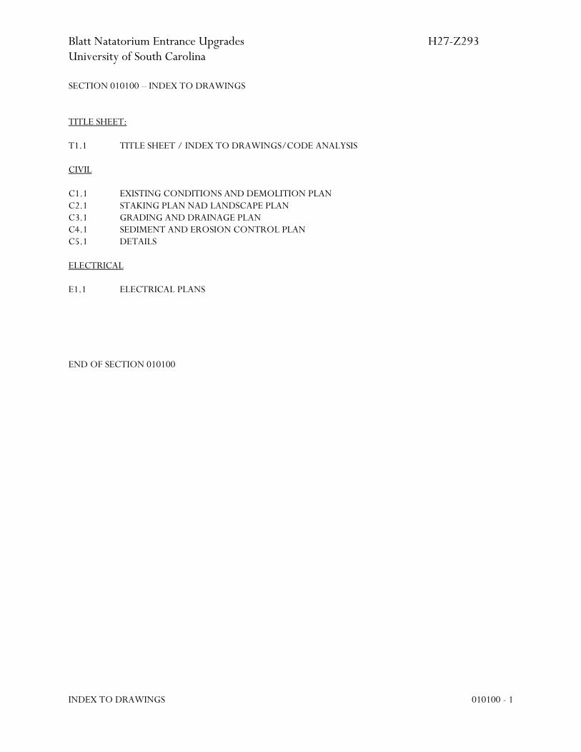
SECTION 010100 – INDEX TO DRAWINGS TITLE SHEET: T1.1 TITLE SHEET / INDEX TO DRAWINGS/CODE ANALYSIS CIVIL C1.1 EXISTING CONDITIONS AND DEMOLITION PLAN C2.1 STAKING PLAN NAD LANDSCAPE PLAN C3.1 GRADING AND DRAINAGE PLAN C4.1 SEDIMENT AND EROSION CONTROL PLAN C5.1 DETAILS ELECTRICAL E1.1 ELECTRICAL PLANS
END OF SECTION 010100

Blatt Natatorium Entrance Upgrades H27-Z293 University of South Carolina
SUMMARY 011000 - 1
SECTION 011000 - SUMMARY
PART 1 - GENERAL
1.1 RELATED DOCUMENTS
A. Drawings and general provisions of the Contract, including General and Supplementary Conditions and other Division 01 Specification Sections, apply to this Section.
1.2 SUMMARY
A. This Section includes the following:
1. Work covered by the Contract Documents. 2. Type of the Contract. 3. Work under other contracts. 4. Products ordered in advance. 5. Use of premises. 6. Owner's occupancy requirements. 7. Work restrictions. 8. Specification formats and conventions.
B. Related Sections include the following:
1. Division 01 Section "Temporary Facilities and Controls" for limitations and procedures governing temporary use of Owner's facilities.
1.3 WORK COVERED BY CONTRACT DOCUMENTS
A. Project Identification:
1. Blatt Natatorium Entrance Upgrades, University of South Carolina. 2. Project Number: H27-Z293. 3. Architects Project Number: U424.16. 4. Project Location: Columbia, South Carolina, 29201.
B. Owner: University of South Carolina.
1. Owner's Representative: Emily Jones, USC Campus Planning & Construction, Project Manager. 803-777-7592.
C. Architect: Garvin Design Group, Inc. 1209 Lincoln St., Columbia, SC 29201. Contact: Becky Brantley. 803-212-1032 (phone) 803-212-1074 (fax).
Blatt Natatorium Entrance Upgrades H27-Z293 University of South Carolina
SUMMARY 011000 - 2
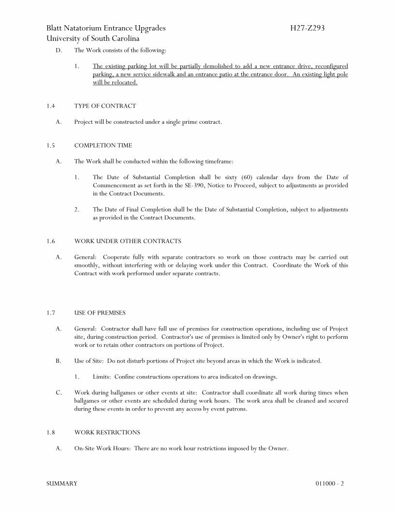
D. The Work consists of the following:
1. The existing parking lot will be partially demolished to add a new entrance drive, reconfigured parking, a new service sidewalk and an entrance patio at the entrance door. An existing light pole will be relocated.
1.4 TYPE OF CONTRACT
A. Project will be constructed under a single prime contract.
1.5 COMPLETION TIME
A. The Work shall be conducted within the following timeframe:
1. The Date of Substantial Completion shall be sixty (60) calendar days from the Date of Commencement as set forth in the SE-390, Notice to Proceed, subject to adjustments as provided in the Contract Documents.
2. The Date of Final Completion shall be the Date of Substantial Completion, subject to adjustments as provided in the Contract Documents.
1.6 WORK UNDER OTHER CONTRACTS
A. General: Cooperate fully with separate contractors so work on those contracts may be carried out smoothly, without interfering with or delaying work under this Contract. Coordinate the Work of this Contract with work performed under separate contracts.
1.7 USE OF PREMISES
A. General: Contractor shall have full use of premises for construction operations, including use of Project site, during construction period. Contractor's use of premises is limited only by Owner's right to perform work or to retain other contractors on portions of Project.
B. Use of Site: Do not disturb portions of Project site beyond areas in which the Work is indicated.
1. Limits: Confine constructions operations to area indicated on drawings.
C. Work during ballgames or other events at site: Contractor shall coordinate all work during times when ballgames or other events are scheduled during work hours. The work area shall be cleaned and secured during these events in order to prevent any access by event patrons.
1.8 WORK RESTRICTIONS
A. On-Site Work Hours: There are no work hour restrictions imposed by the Owner.

Blatt Natatorium Entrance Upgrades H27-Z293 University of South Carolina
SUMMARY 011000 - 3
B. Existing Utility Interruptions: Do not interrupt utilities serving facilities occupied by Owner or othersunless permitted under the following conditions and then only after arranging to provide temporary utilityservices according to requirements indicated:
1. Notify Owner not less than two days in advance of proposed utility interruptions.2. Do not proceed with utility interruptions without Owner's written permission.
1.9 SPECIFICATION FORMATS AND CONVENTIONS
A. Specification Format: The Specifications are organized into Divisions and Sections using the 17-divisionformat and CSI/CSC's "MasterFormat" numbering system.
1. Section Identification: The Specifications use Section numbers and titles to help cross-referencingin the Contract Documents. Sections in the Project Manual are in numeric sequence; however, thesequence is incomplete because all available Section numbers are not used. Consult the table ofcontents at the beginning of the Project Manual to determine numbers and names of Sections in theContract Documents.
2. Division 01: Sections in Division 01 govern the execution of the Work of all Sections in theSpecifications.
B. Specification Content: The Specifications use certain conventions for the style of language and theintended meaning of certain terms, words, and phrases when used in particular situations. Theseconventions are as follows:
1. Abbreviated Language: Language used in the Specifications and other Contract Documents isabbreviated. Words and meanings shall be interpreted as appropriate. Words implied, but notstated, shall be inferred as the sense requires. Singular words shall be interpreted as plural, andplural words shall be interpreted as singular where applicable as the context of the ContractDocuments indicates.
2. Imperative mood and streamlined language are generally used in the Specifications. Requirementsexpressed in the imperative mood are to be performed by Contractor. Occasionally, the indicativeor subjunctive mood may be used in the Section Text for clarity to describe responsibilities thatmust be fulfilled indirectly by Contractor or by others when so noted.
a. The words "shall," "shall be," or "shall comply with," depending on the context, areimplied where a colon (:) is used within a sentence or phrase.
1.10 MISCELLANEOUS PROVISIONS
PART 2 - PRODUCTS (Not Used)
PART 3 - EXECUTION (Not Used)
END OF SECTION 011000

Blatt Natatorium Entrance Upgrades H27-Z293 University of South Carolina
CONTRACT MODIFICATION PROCEDURES 012600 - 1
SECTION 012600- CONTRACT MODIFICATION PROCEDURES
PART 1 - GENERAL
1.1 RELATED DOCUMENTS
A. Drawings and general provisions of the Contract, including General and Supplementary Conditions and other Division 01 Specification Sections, apply to this Section.
1.2 SUMMARY
A. This Section specifies administrative and procedural requirements for handling and processing Contract modifications.
B. Related Sections include the following: 1. Division 01 Section "Product Requirements" for administrative procedures for handling requests
for substitutions made after Contract award.
1.3 MINOR CHANGES IN THE WORK
A. Architect will issue supplemental instructions authorizing Minor Changes in the Work, not involving adjustment to the Contract Sum or the Contract Time, on AIA Document G710, "Architect's Supplemental Instructions."
1.4 PROPOSAL REQUESTS
A. Owner-Initiated Proposal Requests: Architect will issue a detailed description of proposed changes in the Work that may require adjustment to the Contract Sum or the Contract Time. If necessary, the description will include supplemental or revised Drawings and Specifications.
1. Proposal Requests issued by Architect are for information only. Do not consider them instructions either to stop work in progress or to execute the proposed change.
2. Within 10 days after receipt of Proposal Request, submit a quotation estimating cost adjustments to the Contract Sum and the Contract Time necessary to execute the change.
a. Include a list of quantities of products required or eliminated and unit costs, with total amount of purchases and credits to be made. If requested, furnish survey data to substantiate quantities.
b. Indicate applicable taxes, delivery charges, equipment rental, and amounts of trade discounts.
c. Include costs of labor and supervision directly attributable to the change and breakdown into number of people, hourly rates, and total labor.
d. Include an updated Contractor's Construction Schedule that indicates the effect of the change, including, but not limited to, changes in activity duration, start and finish times, and activity relationship. Use available total float before requesting an extension of the Contract Time.

Blatt Natatorium Entrance Upgrades H27-Z293 University of South Carolina
CONTRACT MODIFICATION PROCEDURES 012600 - 2
B. Contractor-Initiated Proposals: If latent or unforeseen conditions require modifications to the Contract,Contractor may propose changes by submitting a request for a change to Architect.
1. Include a statement outlining reasons for the change and the effect of the change on the Work.Provide a complete description of the proposed change. Indicate the effect of the proposed changeon the Contract Sum and the Contract Time.
2. Include a list of quantities of products required or eliminated and unit costs, with total amount ofpurchases and credits to be made. If requested, furnish survey data to substantiate quantities.
3. Indicate applicable taxes, delivery charges, equipment rental, and amounts of trade discounts.4. Include costs of labor and supervision directly attributable to the change.5. Include an updated Contractor's Construction Schedule that indicates the effect of the change,
including, but not limited to, changes in activity duration, start and finish times, and activityrelationship. Use available total float before requesting an extension of the Contract Time.
6. Comply with requirements in Division 01 Section "Product Requirements" if the proposed changerequires substitution of one product or system for product or system specified.
C. Proposal Request Form: Use AIA Document G709 for Proposal Requests.
1.5 CHANGE ORDER PROCEDURES
A. On Owner's approval of a Proposal Request, Architect will issue a Change Order for signatures of Ownerand Contractor on OSE Document SE-380.
1.6 CONSTRUCTION CHANGE DIRECTIVE
A. Construction Change Directive: Architect may issue a Construction Change Directive on AIA DocumentG714. Construction Change Directive instructs Contractor to proceed with a change in the Work, forsubsequent inclusion in a Change Order.
1. Construction Change Directive contains a complete description of change in the Work. It alsodesignates method to be followed to determine change in the Contract Sum or the Contract Time.
B. Documentation: Maintain detailed records on a time and material basis of work required by theConstruction Change Directive.
1. After completion of change, submit an itemized account and supporting data necessary tosubstantiate cost and time adjustments to the Contract.
PART 2 - PRODUCTS (Not Used)
PART 3 - EXECUTION (Not Used)
END OF SECTION 012600
Blatt Natatorium Entrance Upgrades H27-Z293 University of South Carolina
PAYMENT PROCEDURES 012900 - 1
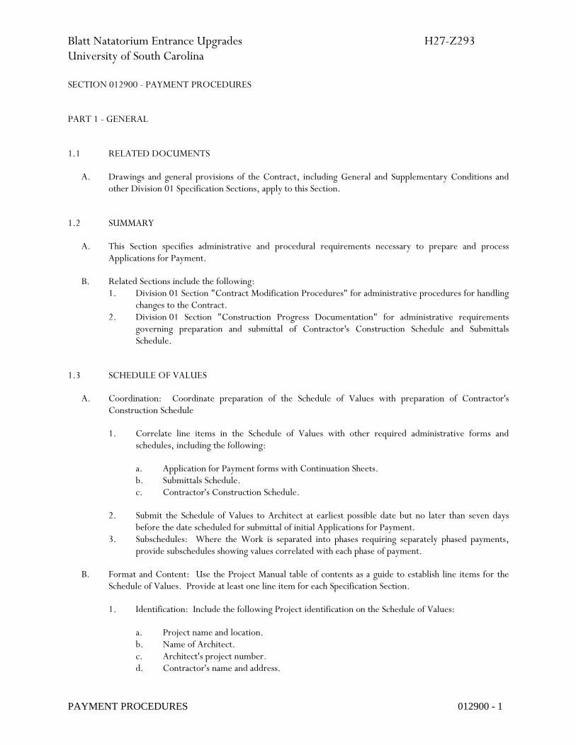
SECTION 012900 - PAYMENT PROCEDURES
PART 1 - GENERAL
1.1 RELATED DOCUMENTS
A. Drawings and general provisions of the Contract, including General and Supplementary Conditions and other Division 01 Specification Sections, apply to this Section.
1.2 SUMMARY
A. This Section specifies administrative and procedural requirements necessary to prepare and process Applications for Payment.
B. Related Sections include the following: 1. Division 01 Section "Contract Modification Procedures" for administrative procedures for handling
changes to the Contract. 2. Division 01 Section "Construction Progress Documentation" for administrative requirements
governing preparation and submittal of Contractor's Construction Schedule and Submittals Schedule.
1.3 SCHEDULE OF VALUES
A. Coordination: Coordinate preparation of the Schedule of Values with preparation of Contractor's Construction Schedule
1. Correlate line items in the Schedule of Values with other required administrative forms and schedules, including the following:
a. Application for Payment forms with Continuation Sheets. b. Submittals Schedule. c. Contractor's Construction Schedule.
2. Submit the Schedule of Values to Architect at earliest possible date but no later than seven days before the date scheduled for submittal of initial Applications for Payment.
3. Subschedules: Where the Work is separated into phases requiring separately phased payments, provide subschedules showing values correlated with each phase of payment.
B. Format and Content: Use the Project Manual table of contents as a guide to establish line items for the Schedule of Values. Provide at least one line item for each Specification Section.
1. Identification: Include the following Project identification on the Schedule of Values:
a. Project name and location. b. Name of Architect. c. Architect's project number. d. Contractor's name and address.

Blatt Natatorium Entrance Upgrades H27-Z293 University of South Carolina
PAYMENT PROCEDURES 012900 - 2
e. Date of submittal.
2. Submit draft of AIA Document G703 Continuation Sheets. 3. Arrange the Schedule of Values in tabular form with separate columns to indicate the following for
each item listed:
a. Related Specification Section or Division. b. Description of the Work. c. Name of subcontractor. d. Name of manufacturer or fabricator. e. Name of supplier. f. Change Orders (numbers) that affect value. g. Dollar value.
1) Percentage of the Contract Sum to nearest one-hundredth percent, adjusted to total 100 percent.
4. Provide a breakdown of the Contract Sum in enough detail to facilitate continued evaluation of Applications for Payment and progress reports. Coordinate with the Project Manual table of contents. Provide several line items for principal subcontract amounts, where appropriate.
5. Round amounts to nearest whole dollar; total shall equal the Contract Sum. 6. Provide a separate line item in the Schedule of Values for each part of the Work where Applications
for Payment may include materials or equipment purchased or fabricated and stored, but not yet installed.
a. Differentiate between items stored on-site and items stored off-site. If specified, include evidence of insurance or bonded warehousing.
7. Provide separate line items in the Schedule of Values for initial cost of materials, for each subsequent stage of completion, and for total installed value of that part of the Work.
8. Allowances: Provide a separate line item in the Schedule of Values for each allowance. Show line-item value of unit-cost allowances, as a product of the unit cost, multiplied by measured quantity. Use information indicated in the Contract Documents to determine quantities.
9. Each item in the Schedule of Values and Applications for Payment shall be complete. Include total cost and proportionate share of general overhead and profit for each item.
a. Temporary facilities and other major cost items that are not direct cost of actual work-in-place may be shown either as separate line items in the Schedule of Values or distributed as general overhead expense, at Contractor's option.
10. Show each Change Order as a new line item or a separate sheet.
1.4 APPLICATIONS FOR PAYMENT
A. Each Application for Payment shall be consistent with previous applications and payments as certified by Architect and paid for by Owner.
1. Initial Application for Payment, Application for Payment at time of Substantial Completion, and final Application for Payment involve additional requirements.
Blatt Natatorium Entrance Upgrades H27-Z293 University of South Carolina
PAYMENT PROCEDURES 012900 - 3
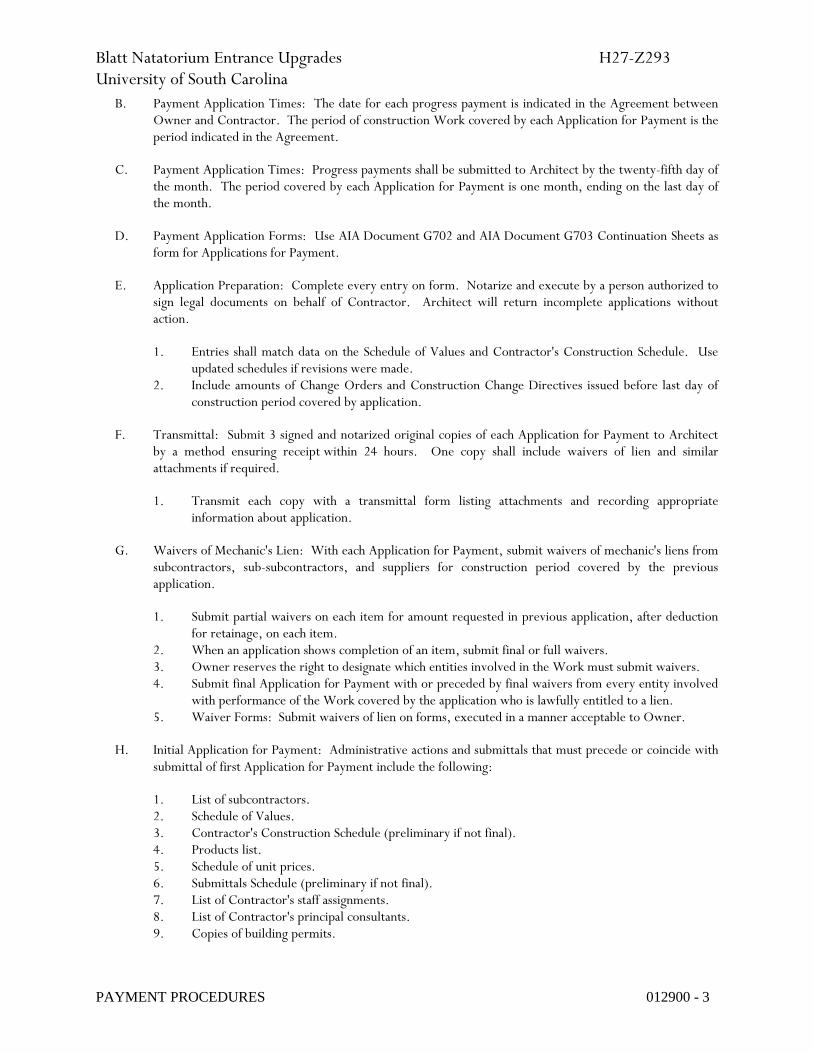
B. Payment Application Times: The date for each progress payment is indicated in the Agreement between Owner and Contractor. The period of construction Work covered by each Application for Payment is the period indicated in the Agreement.
C. Payment Application Times: Progress payments shall be submitted to Architect by the twenty-fifth day of the month. The period covered by each Application for Payment is one month, ending on the last day of the month.
D. Payment Application Forms: Use AIA Document G702 and AIA Document G703 Continuation Sheets as form for Applications for Payment.
E. Application Preparation: Complete every entry on form. Notarize and execute by a person authorized to sign legal documents on behalf of Contractor. Architect will return incomplete applications without action.
1. Entries shall match data on the Schedule of Values and Contractor's Construction Schedule. Use updated schedules if revisions were made.
2. Include amounts of Change Orders and Construction Change Directives issued before last day of construction period covered by application.
F. Transmittal: Submit 3 signed and notarized original copies of each Application for Payment to Architect by a method ensuring receipt within 24 hours. One copy shall include waivers of lien and similar attachments if required.
1. Transmit each copy with a transmittal form listing attachments and recording appropriate information about application.
G. Waivers of Mechanic's Lien: With each Application for Payment, submit waivers of mechanic's liens from subcontractors, sub-subcontractors, and suppliers for construction period covered by the previous application.
1. Submit partial waivers on each item for amount requested in previous application, after deduction for retainage, on each item.
2. When an application shows completion of an item, submit final or full waivers. 3. Owner reserves the right to designate which entities involved in the Work must submit waivers. 4. Submit final Application for Payment with or preceded by final waivers from every entity involved
with performance of the Work covered by the application who is lawfully entitled to a lien. 5. Waiver Forms: Submit waivers of lien on forms, executed in a manner acceptable to Owner.
H. Initial Application for Payment: Administrative actions and submittals that must precede or coincide with submittal of first Application for Payment include the following:
1. List of subcontractors. 2. Schedule of Values. 3. Contractor's Construction Schedule (preliminary if not final). 4. Products list. 5. Schedule of unit prices. 6. Submittals Schedule (preliminary if not final). 7. List of Contractor's staff assignments. 8. List of Contractor's principal consultants. 9. Copies of building permits.

Blatt Natatorium Entrance Upgrades H27-Z293 University of South Carolina
PAYMENT PROCEDURES 012900 - 4
10. Copies of authorizations and licenses from authorities having jurisdiction for performance of the Work.
11. Initial progress report. 12. Report of preconstruction conference. 13. Certificates of insurance and insurance policies.
I. Application for Payment at Substantial Completion: After issuing the Certificate of Substantial Completion, submit an Application for Payment showing 100 percent completion for portion of the Work claimed as substantially complete.
1. Include documentation supporting claim that the Work is substantially complete and a statement showing an accounting of changes to the Contract Sum.
2. This application shall reflect Certificates of Partial Substantial Completion issued previously for Owner occupancy of designated portions of the Work.
J. Final Payment Application: Submit final Application for Payment with releases and supporting documentation not previously submitted and accepted, including, but not limited, to the following:
1. Evidence of completion of Project closeout requirements. 2. Insurance certificates for products and completed operations where required and proof that taxes,
fees, and similar obligations were paid. 3. Updated final statement, accounting for final changes to the Contract Sum. 4. AIA Document G706, "Contractor's Affidavit of Payment of Debts and Claims." 5. AIA Document G706A, "Contractor's Affidavit of Release of Liens." 6. AIA Document G707, "Consent of Surety to Final Payment." 7. Evidence that claims have been settled. 8. Final meter readings for utilities, a measured record of stored fuel, and similar data as of date of
Substantial Completion or when Owner took possession of and assumed responsibility for corresponding elements of the Work.
9. Final, liquidated damages settlement statement.
PART 2 - PRODUCTS (Not Used)
PART 3 - EXECUTION (Not Used)
END OF SECTION 012900

Blatt Natatorium Entrance Upgrades H27-Z293 University of South Carolina
PROJECT MANAGEMENT AND COORDINATION 013100 - 1
SECTION 013100 - PROJECT MANAGEMENT AND COORDINATION
PART 1 - GENERAL
1.1 RELATED DOCUMENTS
A. Drawings and general provisions of the Contract, including General and Supplementary Conditions and other Division 01 Specification Sections, apply to this Section.
1.2 SUMMARY
A. This Section includes administrative provisions for coordinating construction operations on Project including, but not limited to, the following:
1. Administrative and supervisory personnel. 2. Project meetings. 3. Requests for Interpretation (RFIs).
B. Each contractor shall participate in coordination requirements. Certain areas of responsibility will be assigned to a specific contractor.
C. Related Sections include the following: 1. Division 01 Section "Construction Progress Documentation" for preparing and submitting
Contractor's Construction Schedule. 2. Division 01 Section "Execution" for procedures for coordinating general installation and field-
engineering services, including establishment of benchmarks and control points. 3. Division 01 Section "Closeout Procedures" for coordinating closeout of the Contract.
1.3 DEFINITIONS
A. RFI: Request from Contractor seeking interpretation or clarification of the Contract Documents.
1.4 COORDINATION
A. Coordination: Each contractor shall coordinate its construction operations with those of other contractors and entities to ensure efficient and orderly installation of each part of the Work. Each contractor shall coordinate its operations with operations, included in different Sections, that depend on each other for proper installation, connection, and operation.
1. Schedule construction operations in sequence required to obtain the best results where installation of one part of the Work depends on installation of other components, before or after its own installation.
2. Coordinate installation of different components with other contractors to ensure maximum accessibility for required maintenance, service, and repair.
3. Make adequate provisions to accommodate items scheduled for later installation.

Blatt Natatorium Entrance Upgrades H27-Z293 University of South Carolina
PROJECT MANAGEMENT AND COORDINATION 013100 - 2
4. Where availability of space is limited, coordinate installation of different components to ensure maximum performance and accessibility for required maintenance, service, and repair of all components, including mechanical and electrical.
B. Prepare memoranda for distribution to each party involved, outlining special procedures required for coordination. Include such items as required notices, reports, and list of attendees at meetings.
1. Prepare similar memoranda for Owner and separate contractors if coordination of their Work is required.
C. Administrative Procedures: Coordinate scheduling and timing of required administrative procedures with other construction activities and activities of other contractors to avoid conflicts and to ensure orderly progress of the Work. Such administrative activities include, but are not limited to, the following:
1. Preparation of Contractor's Construction Schedule. 2. Preparation of the Schedule of Values. 3. Installation and removal of temporary facilities and controls. 4. Delivery and processing of submittals. 5. Progress meetings. 6. Preinstallation conferences. 7. Project closeout activities. 8. Startup and adjustment of systems. 9. Project closeout activities.
D. Conservation: Coordinate construction activities to ensure that operations are carried out with consideration given to conservation of energy, water, and materials.
1. Salvage materials and equipment involved in performance of, but not actually incorporated into, the Work. Refer to other Sections for disposition of salvaged materials that are designated as Owner's property.
1.5 SUBMITTALS
A. Key Personnel Names: Within 7 days of starting construction operations, submit a list of key personnel assignments, including superintendent and other personnel in attendance at Project site. Identify individuals and their duties and responsibilities; list addresses and telephone numbers, including home and office telephone numbers. Provide names, addresses, and telephone numbers of individuals assigned as standbys in the absence of individuals assigned to Project.
1. Post copies of list in Project meeting room, in temporary field office, and by each temporary telephone. Keep list current at all times.
1.6 ADMINISTRATIVE AND SUPERVISORY PERSONNEL
A. General: In addition to Project superintendent, provide other administrative and supervisory personnel as required for proper performance of the Work.
1. Include special personnel required for coordination of operations with other contractors.

Blatt Natatorium Entrance Upgrades H27-Z293 University of South Carolina
PROJECT MANAGEMENT AND COORDINATION 013100 - 3
1.7 PROJECT MEETINGS
A. General: Schedule and conduct meetings and conferences at Project site, unless otherwise indicated.
1. Attendees: Inform participants and others involved, and individuals whose presence is required, of date and time of each meeting. Notify Owner and Architect of scheduled meeting dates and times.
2. Agenda: Prepare the meeting agenda. Distribute the agenda to all invited attendees. 3. Minutes: Record significant discussions and agreements achieved. Distribute the meeting minutes
to everyone concerned, including Owner and Architect, within three days of the meeting.
B. Preconstruction Conference: Schedule a preconstruction conference before starting construction, at a time convenient to Owner and Architect, but no later than 10 days after Notice To Proceed. Hold the conference at Project site or another convenient location. Conduct the meeting to review responsibilities and personnel assignments.
1. Attendees: Authorized representatives of Owner, Architect, and their consultants; Contractor and its superintendent; major subcontractors; suppliers; and other concerned parties shall attend the conference. All participants at the conference shall be familiar with Project and authorized to conclude matters relating to the Work.
2. Agenda: Discuss items of significance that could affect progress, including the following:
a. Tentative construction schedule.
b. Preparation for and submission of Coordination Drawings. c. Phasing. d. Critical work sequencing and long-lead items. e. Designation of key personnel and their duties. f. Procedures for processing field decisions and Change Orders. g. Procedures for RFIs. h. Procedures for testing and inspecting. i. Procedures for processing Applications for Payment. j. Distribution of the Contract Documents. k. Submittal procedures. l. Preparation of Record Documents. m. Use of the premises. n. Work restrictions. o. Owner's occupancy requirements. p. Responsibility for temporary facilities and controls. q. Construction waste management and recycling. r. Parking availability. s. Office, work, and storage areas. t. Equipment deliveries and priorities. u. First aid. v. Security. w. Progress cleaning. x. Working hours.
3. Minutes: Architect will record and distribute meeting minutes.
C. Preinstallation Conferences: Conduct a preinstallation conference at Project site before each construction activity that requires coordination with other construction.

Blatt Natatorium Entrance Upgrades H27-Z293 University of South Carolina
PROJECT MANAGEMENT AND COORDINATION 013100 - 4
1. Attendees: Installer and representatives of manufacturers and fabricators involved in or affected by the installation and its coordination or integration with other materials and installations that have preceded or will follow, shall attend the meeting. Advise Architect of scheduled meeting dates.
2. Agenda: Review progress of other construction activities and preparations for the particular activity under consideration, including requirements for the following:
a. The Contract Documents. b. Options. c. Related RFIs. d. Related Change Orders. e. Purchases. f. Deliveries. g. Submittals. h. Review of mockups. i. Possible conflicts. j. Compatibility problems. k. Time schedules. l. Weather limitations. m. Manufacturer's written recommendations. n. Warranty requirements. o. Compatibility of materials. p. Acceptability of substrates. q. Temporary facilities and controls. r. Space and access limitations. s. Regulations of authorities having jurisdiction. t. Testing and inspecting requirements. u. Installation procedures. v. Coordination with other work. w. Required performance results. x. Protection of adjacent work. y. Protection of construction and personnel.
3. Record significant conference discussions, agreements, and disagreements, including required corrective measures and actions.
4. Reporting: Distribute minutes of the meeting to each party present and to parties who should have been present.
5. Do not proceed with installation if the conference cannot be successfully concluded. Initiate whatever actions are necessary to resolve impediments to performance of the Work and reconvene the conference at earliest feasible date.
D. Progress Meetings: Conduct progress meetings at regular intervals. Coordinate dates of meetings with preparation of payment requests.
1. Attendees: In addition to representatives of Owner, and Architect, each contractor, subcontractor, supplier, and other entity concerned with current progress or involved in planning, coordination, or performance of future activities shall be represented at these meetings. All participants at the conference shall be familiar with Project and authorized to conclude matters relating to the Work.
2. Agenda: Review and correct or approve minutes of previous progress meeting. Review other items of significance that could affect progress. Include topics for discussion as appropriate to status of Project.

Blatt Natatorium Entrance Upgrades H27-Z293 University of South Carolina
PROJECT MANAGEMENT AND COORDINATION 013100 - 5
a. Contractor's Construction Schedule: Review progress since the last meeting. Determine whether each activity is on time, ahead of schedule, or behind schedule, in relation to Contractor's Construction Schedule. Determine how construction behind schedule will be expedited; secure commitments from parties involved to do so. Discuss whether schedule revisions are required to ensure that current and subsequent activities will be completed within the Contract Time.
1) Review schedule for next period.
b. Review present and future needs of each entity present, including the following:
1) Interface requirements. 2) Sequence of operations. 3) Status of submittals. 4) Deliveries. 5) Off-site fabrication. 6) Access. 7) Site utilization. 8) Temporary facilities and controls. 9) Work hours. 10) Hazards and risks. 11) Progress cleaning. 12) Quality and work standards. 13) Status of correction of deficient items. 14) Field observations. 15) RFIs. 16) Status of proposal requests. 17) Pending changes. 18) Status of Change Orders. 19) Pending claims and disputes. 20) Documentation of information for payment requests.
3. Minutes: Contractor will record and distribute to all parties present the meeting minutes. 4. Reporting: Distribute minutes of the meeting to each party present and to parties who should have
been present.
a. Schedule Updating: Revise Contractor's Construction Schedule after each progress meeting where revisions to the schedule have been made or recognized. Issue revised schedule concurrently with the report of each meeting.
E. Coordination Meetings: Conduct Project coordination meetings at weekly intervals (for specific trades as needed during course of the project). Project coordination meetings are in addition to specific meetings held for other purposes, such as progress meetings and preinstallation conferences.
1. Attendees: In addition to representatives of Owner and Architect, each contractor, subcontractor, supplier, and other entity concerned with current progress or involved in planning, coordination, or performance of future activities shall be represented at these meetings. All participants at the conference shall be familiar with Project and authorized to conclude matters relating to the Work.
2. Agenda: Review and correct or approve minutes of the previous coordination meeting. Review other items of significance that could affect progress. Include topics for discussion as appropriate to status of Project.

Blatt Natatorium Entrance Upgrades H27-Z293 University of South Carolina
PROJECT MANAGEMENT AND COORDINATION 013100 - 6
a. Combined Contractor's Construction Schedule: Review progress since the last coordination meeting. Determine whether each contract is on time, ahead of schedule, or behind schedule, in relation to Combined Contractor's Construction Schedule. Determine how construction behind schedule will be expedited; secure commitments from parties involved to do so. Discuss whether schedule revisions are required to ensure that current and subsequent activities will be completed within the Contract Time.
b. Schedule Updating: Revise Combined Contractor's Construction Schedule after each coordination meeting where revisions to the schedule have been made or recognized. Issue revised schedule concurrently with report of each meeting.
c. Review present and future needs of each contractor present, including the following:
1) Interface requirements. 2) Sequence of operations. 3) Status of submittals. 4) Deliveries. 5) Off-site fabrication. 6) Access. 7) Site utilization. 8) Temporary facilities and controls. 9) Work hours. 10) Hazards and risks. 11) Progress cleaning. 12) Quality and work standards. 13) Change Orders.
3. Reporting: Record meeting results and distribute copies to everyone in attendance and to others affected by decisions or actions resulting from each meeting.
1.8 REQUESTS FOR INTERPRETATION (RFIs)
A. Procedure: Immediately on discovery of the need for interpretation of the Contract Documents, and if not possible to request interpretation at Project meeting, prepare and submit an RFI in the form specified.
1. RFIs shall originate with Contractor. RFIs submitted by entities other than Contractor will be returned with no response.
2. Coordinate and submit RFIs in a prompt manner so as to avoid delays in Contractor's work or work of subcontractors.
B. Content of the RFI: Include a detailed, legible description of item needing interpretation and the following:
1. Project name. 2. Date. 3. Name of Contractor. 4. Name of Architect. 5. RFI number, numbered sequentially. 6. Specification Section number and title and related paragraphs, as appropriate. 7. Drawing number and detail references, as appropriate. 8. Field dimensions and conditions, as appropriate.

Blatt Natatorium Entrance Upgrades H27-Z293 University of South Carolina
PROJECT MANAGEMENT AND COORDINATION 013100 - 7
9. Contractor's suggested solution(s). If Contractor's solution(s) impact the Contract Time or the Contract Sum, Contractor shall state impact in the RFI.
10. Contractor's signature. 11. Attachments: Include drawings, descriptions, measurements, photos, Product Data, Shop
Drawings, and other information necessary to fully describe items needing interpretation.
a. Supplementary drawings prepared by Contractor shall include dimensions, thicknesses, structural grid references, and details of affected materials, assemblies, and attachments.
C. Hard-Copy RFIs: as agreed upon.
1. Identify each page of attachments with the RFI number and sequential page number.
D. Software-Generated RFIs: Software-generated form with substantially the same content as indicated above.
1. Attachments shall be electronic files in Adobe Acrobat PDF format.
E. Architect's Action: Architect will review each RFI, determine action required, and return it. Allow seven working days for Architect's response for each RFI. RFIs received after 1:00 p.m. will be considered as received the following working day.
1. The following RFIs will be returned without action:
a. Requests for approval of submittals. b. Requests for approval of substitutions. c. Requests for coordination information already indicated in the Contract Documents. d. Requests for adjustments in the Contract Time or the Contract Sum. e. Requests for interpretation of Architect's actions on submittals. f. Incomplete RFIs or RFIs with numerous errors.
2. Architect's action may include a request for additional information, in which case Architect's time for response will start again.
3. Architect's action on RFIs that may result in a change to the Contract Time or the Contract Sum may be eligible for Contractor to submit Change Proposal according to Division 01 Section "Contract Modification Procedures."
a. If Contractor believes the RFI response warrants change in the Contract Time or the Contract Sum, notify Architect in writing within 10 days of receipt of the RFI response.
F. On receipt of Architect's action, update the RFI log and immediately distribute the RFI response to affected parties. Review response and notify Architect within seven days if Contractor disagrees with response.
G. RFI Log: Prepare, maintain, and submit a tabular log of RFIs organized by the RFI number. Submit log weekly. Include the following:
1. Project name. 2. Name and address of Contractor. 3. Name and address of Architect. 4. RFI number including RFIs that were dropped and not submitted. 5. RFI description.
Blatt Natatorium Entrance Upgrades H27-Z293 University of South Carolina
PROJECT MANAGEMENT AND COORDINATION 013100 - 8
6. Date the RFI was submitted. 7. Date Architect's response was received. 8. Identification of related Minor Change in the Work, Construction Change Directive, and Proposal
Request, as appropriate. 9. Identification of related Field Order, Work Change Directive, and Proposal Request, as
appropriate.
PART 2 - PRODUCTS (Not Used)
PART 3 - EXECUTION (Not Used)
END OF SECTION 013100

Blatt Natatorium Entrance Upgrades H27-Z293 University of South Carolina
CONSTRUCTION PROGRESS DOCUMENTATION 013200 - 1
SECTION 013200 - CONSTRUCTION PROGRESS DOCUMENTATION
PART 1 - GENERAL
1.1 RELATED DOCUMENTS
A. Drawings and general provisions of the Contract, including General and Supplementary Conditions and other Division 01 Specification Sections, apply to this Section.
1.2 SUMMARY
A. This Section includes administrative and procedural requirements for documenting the progress of construction during performance of the Work, including the following:
1. Preliminary Construction Schedule. 2. Contractor's Construction Schedule. 3. Submittals Schedule. 4. Daily construction reports. 5. Material location reports. 6. Field condition reports. 7. Special reports.
B. Related Sections include the following: 1. Division 01 Section "Project Management and Coordination" for submitting and distributing
meeting and conference minutes. 2. Division 01 Section "Submittal Procedures" for submitting schedules and reports. 3. Division 01 Section "Quality Requirements" for submitting a schedule of tests and inspections.
1.3 DEFINITIONS
A. Activity: A discrete part of a project that can be identified for planning, scheduling, monitoring, and controlling the construction project. Activities included in a construction schedule consume time and resources.
1. Critical activities are activities on the critical path. They must start and finish on the planned early start and finish times.
2. Predecessor Activity: An activity that precedes another activity in the network. 3. Successor Activity: An activity that follows another activity in the network.
B. CPM: Critical path method, which is a method of planning and scheduling a construction project where activities are arranged based on activity relationships. Network calculations determine when activities can be performed and the critical path of Project.
C. Critical Path: The longest connected chain of interdependent activities through the network schedule that establishes the minimum overall Project duration and contains no float.
D. Event: The starting or ending point of an activity.

Blatt Natatorium Entrance Upgrades H27-Z293 University of South Carolina
CONSTRUCTION PROGRESS DOCUMENTATION 013200 - 2
E. Float: The measure of leeway in starting and completing an activity.
1. Float time is not for the exclusive use or benefit of either Owner or Contractor, but is a jointly owned, expiring Project resource available to both parties as needed to meet schedule milestones and Contract completion date.
2. Free float is the amount of time an activity can be delayed without adversely affecting the early start of the successor activity.
3. Total float is the measure of leeway in starting or completing an activity without adversely affecting the planned Project completion date.
F. Fragnet: A partial or fragmentary network that breaks down activities into smaller activities for greater detail.
G. Major Area: A story of construction, a separate building, or a similar significant construction element.
H. Milestone: A key or critical point in time for reference or measurement.
I. Network Diagram: A graphic diagram of a network schedule, showing activities and activity relationships.
J. Resource Loading: The allocation of manpower and equipment necessary for the completion of an activity as scheduled.
1.4 SUBMITTALS
A. Qualification Data: For scheduling consultant.
B. Submittals Schedule: Submit three copies of schedule. Arrange the following information in a tabular format:
1. Scheduled date for first submittal. 2. Specification Section number and title. 3. Submittal category (action or informational). 4. Name of subcontractor. 5. Description of the Work covered. 6. Scheduled date for Architect's final release or approval.
C. Preliminary Construction Schedule: Submit three opaque copies.
D. Preliminary Network Diagram: Submit three opaque copies, large enough to show entire network for entire construction period. Show logic ties for activities.
E. Contractor's Construction Schedule: Submit three opaque copies of initial schedule, large enough to show entire schedule for entire construction period.
1. Submit an electronic copy of schedule, using software indicated, on CD-R, and labeled to comply with requirements for submittals. Include type of schedule (Initial or Updated) and date on label.
F. CPM Reports: Concurrent with CPM schedule, submit three copies of each of the following computer-generated reports. Format for each activity in reports shall contain activity number, activity description, cost and resource loading, original duration, remaining duration, early start date, early finish date, late start date, late finish date, and total float in calendar days.
Blatt Natatorium Entrance Upgrades H27-Z293 University of South Carolina
CONSTRUCTION PROGRESS DOCUMENTATION 013200 - 3
1. Activity Report: List of all activities sorted by activity number and then early start date, or actual start date if known.
2. Logic Report: List of preceding and succeeding activities for all activities, sorted in ascending order by activity number and then early start date, or actual start date if known.
3. Total Float Report: List of all activities sorted in ascending order of total float.
G. Weekly Construction Reports: Submit two copies at weekly intervals.
H. Field Condition Reports: Submit two copies at time of discovery of differing conditions.
1.5 QUALITY ASSURANCE
A. Scheduling Consultant Qualifications: An experienced specialist in CPM scheduling and reporting, with capability of producing CPM reports and diagrams within 24 hours of Architect's request.
B. Prescheduling Conference: Conduct conference at Project site to comply with requirements in Division 01 Section "Project Management and Coordination." Review methods and procedures related to the Preliminary Construction Schedule and Contractor's Construction Schedule, including, but not limited to, the following:
1. Review software limitations and content and format for reports. 2. Verify availability of qualified personnel needed to develop and update schedule. 3. Discuss constraints, including phasing, work stages, interim milestones and partial Owner
occupancy. 4. Review delivery dates for Owner-furnished products. 5. Review schedule for work of Owner's separate contracts. 6. Review time required for review of submittals and resubmittals. 7. Review requirements for tests and inspections by independent testing and inspecting agencies. 8. Review time required for completion and startup procedures. 9. Review and finalize list of construction activities to be included in schedule. 10. Review submittal requirements and procedures. 11. Review procedures for updating schedule.
1.6 COORDINATION
A. Coordinate preparation and processing of schedules and reports with performance of construction activities and with scheduling and reporting of separate contractors.
B. Coordinate Contractor's Construction Schedule with the Schedule of Values, list of subcontracts, Submittals Schedule, progress reports, payment requests, and other required schedules and reports.
1. Secure time commitments for performing critical elements of the Work from parties involved. 2. Coordinate each construction activity in the network with other activities and schedule them in
proper sequence.

Blatt Natatorium Entrance Upgrades H27-Z293 University of South Carolina
CONSTRUCTION PROGRESS DOCUMENTATION 013200 - 4
PART 2 - PRODUCTS
2.1 SUBMITTALS SCHEDULE
A. Preparation: Submit a schedule of submittals, arranged in chronological order by dates required by construction schedule. Include time required for review, resubmittal, ordering, manufacturing, fabrication, and delivery when establishing dates.
1. Coordinate Submittals Schedule with list of subcontracts, the Schedule of Values, and Contractor's Construction Schedule.
2. Initial Submittal: Submit concurrently with preliminary bar-chart schedule. Include submittals required during the first 60 days of construction. List those required to maintain orderly progress of the Work and those required early because of long lead time for manufacture or fabrication.
a. At Contractor's option, show submittals on the Preliminary Construction Schedule, instead of tabulating them separately.
3. Final Submittal: Submit concurrently with the first complete submittal of Contractor's Construction Schedule.
2.2 CONTRACTOR'S CONSTRUCTION SCHEDULE, GENERAL
A. Procedures: Comply with procedures contained in AGC's "Construction Planning & Scheduling."
B. Time Frame: Extend schedule from date established for commencement of the Work to date of Substantial and Final Completion.
1. Contract completion date shall not be changed by submission of a schedule that shows an early completion date, unless specifically authorized by Change Order.
C. Activities: Treat each story or separate area as a separate numbered activity for each principal element of the Work. Comply with the following:
1. Activity Duration: Define activities so no activity is longer than 14 days, unless specifically allowed by Architect.
2. Procurement Activities: Include procurement process activities for the following long lead items and major items, requiring a cycle of more than 60 days, as separate activities in schedule. Procurement cycle activities include, but are not limited to, submittals, approvals, purchasing, fabrication, and delivery.
3. Submittal Review Time: Include review and resubmittal times indicated in Division 01 Section "Submittal Procedures" in schedule. Coordinate submittal review times in Contractor's Construction Schedule with Submittals Schedule.
4. Startup and Testing Time: Include not less than 10 days for startup and testing. 5. Substantial Completion: Indicate completion in advance of date established for Substantial
Completion, and allow time for Architect's administrative procedures necessary for certification of Substantial Completion.
D. Constraints: Include constraints and work restrictions indicated in the Contract Documents and as follows in schedule, and show how the sequence of the Work is affected.

Blatt Natatorium Entrance Upgrades H27-Z293 University of South Carolina
CONSTRUCTION PROGRESS DOCUMENTATION 013200 - 5
1. Phasing: Arrange list of activities on schedule by phase. 2. Work under More Than One Contract: Include a separate activity for each contract. 3. Work by Owner: Include a separate activity for each portion of the Work performed by Owner. 4. Products Ordered in Advance: Include a separate activity for each product. Include delivery date
indicated in Division 01 Section "Summary." Delivery dates indicated stipulate the earliest possible delivery date.
5. Owner-Furnished Products: Include a separate activity for each product. Include delivery date indicated in Division 01 Section "Summary." Delivery dates indicated stipulate the earliest possible delivery date.
6. Work Restrictions: Show the effect of the following items on the schedule: a. Partial occupancy before Substantial Completion. b. Use of premises restrictions. c. Seasonal variations. d. Environmental control.
7. Work Stages: Indicate important stages of construction for each major portion of the Work, including, but not limited to, the following:
a. Subcontract awards. b. Submittals. c. Purchases. d. Mockups. e. Fabrication. f. Sample testing. g. Deliveries. h. Installation. i. Tests and inspections. j. Adjusting. k. Curing. l. Startup and placement into final use and operation.
8. Area Separations: Identify each major area of construction for each major portion of the Work. Indicate where each construction activity within a major area must be sequenced or integrated with other construction activities to provide for the following:
a. Structural completion. b. Permanent space enclosure. c. Completion of mechanical installation. d. Completion of electrical installation. e. Substantial Completion.
E. Milestones: Include milestones indicated in the Contract Documents in schedule, including, but not limited to, the Notice to Proceed, Substantial Completion, and Final Completion, and significant interim milestones:
F. Contract Modifications: For each proposed contract modification and concurrent with its submission, prepare a time-impact analysis using fragnets to demonstrate the effect of the proposed change on the overall project schedule.
G. Computer Software: Prepare schedules using a program that has been developed specifically to manage construction schedules.

Blatt Natatorium Entrance Upgrades H27-Z293 University of South Carolina
CONSTRUCTION PROGRESS DOCUMENTATION 013200 - 6
2.3 PRELIMINARY CONSTRUCTION SCHEDULE
A. Bar-Chart Schedule: Submit preliminary horizontal bar-chart-type construction schedule within 14 days of date established for commencement of the Work.
B. Preparation: Indicate each significant construction activity separately. Identify first workday of each week with a continuous vertical line. Outline significant construction activities for first 60 days of construction. Include skeleton diagram for the remainder of the Work.
2.4 CONTRACTOR'S CONSTRUCTION SCHEDULE (CPM SCHEDULE)
A. General: Prepare network diagrams using AON (activity-on-node) format.
B. Preliminary Network Diagram: Submit diagram within 14 days of date established for commencement of the Work. Outline significant construction activities for the first 60 days of construction. Include skeleton diagram for the remainder of the Work and a cash requirement prediction based on indicated activities.
C. CPM Schedule: Prepare Contractor's Construction Schedule using a computerized, cost- and resource-loaded, time-scaled CPM network analysis diagram for the Work.
1. Develop network diagram in sufficient time to submit CPM schedule so it can be accepted for use no later than 30 days after date established for commencement of the Work.
a. Failure to include any work item required for performance of this Contract shall not excuse Contractor from completing all work within applicable completion dates, regardless of Architect's approval of the schedule.
2. Conduct educational workshops to train and inform key Project personnel, including subcontractors' personnel, in proper methods of providing data and using CPM schedule information.
3. Establish procedures for monitoring and updating CPM schedule and for reporting progress. Coordinate procedures with progress meeting and payment request dates.
4. Use "one workday" as the unit of time. Include list of nonworking days and holidays incorporated into the schedule.
D. CPM Schedule Preparation: Prepare a list of all activities required to complete the Work. Using the preliminary network diagram, prepare a skeleton network to identify probable critical paths.
1. Activities: Indicate the estimated time duration, sequence requirements, and relationship of each activity in relation to other activities. Include estimated time frames for the following activities:
a. Preparation and processing of submittals. b. Mobilization and demobilization. c. Purchase of materials. d. Delivery. e. Fabrication. f. Utility interruptions. g. Installation. h. Work by Owner that may affect or be affected by Contractor's activities. i. Testing and commissioning.
Blatt Natatorium Entrance Upgrades H27-Z293 University of South Carolina
CONSTRUCTION PROGRESS DOCUMENTATION 013200 - 7
2. Critical Path Activities: Identify critical path activities, including those for interim completion dates. Scheduled start and completion dates shall be consistent with Contract milestone dates.
3. Processing: Process data to produce output data on a computer-drawn, time-scaled network. Revise data, reorganize activity sequences, and reproduce as often as necessary to produce the CPM schedule within the limitations of the Contract Time.
4. Format: Mark the critical path. Locate the critical path near center of network; locate paths with most float near the edges.
a. Sub-networks on separate sheets are permissible for activities clearly off the critical path.
E. Initial Issue of Schedule: Prepare initial network diagram from a list of straight "early start-total float" sort. Identify critical activities. Prepare tabulated reports showing the following:
1. Contractor or subcontractor and the Work or activity. 2. Description of activity. 3. Principal events of activity. 4. Immediate preceding and succeeding activities. 5. Early and late start dates. 6. Early and late finish dates. 7. Activity duration in workdays. 8. Total float or slack time. 9. Average size of workforce. 10. Dollar value of activity (coordinated with the Schedule of Values).
F. Schedule Updating: Concurrent with making revisions to schedule, prepare tabulated reports showing the following:
1. Identification of activities that have changed. 2. Changes in early and late start dates. 3. Changes in early and late finish dates. 4. Changes in activity durations in workdays. 5. Changes in the critical path. 6. Changes in total float or slack time. 7. Changes in the Contract Time.
2.5 REPORTS
A. Daily Construction Reports: Prepare a daily construction report recording the following information concerning events at Project site:
1. List of subcontractors at Project site. 2. List of separate contractors at Project site. 3. Approximate count of personnel at Project site. 4. Equipment at Project site. 5. Material deliveries. 6. High and low temperatures and general weather conditions. 7. Accidents. 8. Meetings and significant decisions. 9. Unusual events (refer to special reports). 10. Stoppages, delays, shortages, and losses.

Blatt Natatorium Entrance Upgrades H27-Z293 University of South Carolina
CONSTRUCTION PROGRESS DOCUMENTATION 013200 - 8
11. Meter readings and similar recordings. 12. Emergency procedures. 13. Orders and requests of authorities having jurisdiction. 14. Change Orders received and implemented. 15. Construction Change Directives received and implemented. 16. Services connected and disconnected. 17. Equipment or system tests and startups. 18. Partial Completions and occupancies. 19. Substantial Completions authorized.
B. Material Location Reports: At monthly intervals, prepare and submit a comprehensive list of materials delivered to and stored at Project site. List shall be cumulative, showing materials previously reported plus items recently delivered. Include with list a statement of progress on and delivery dates for materials or items of equipment fabricated or stored away from Project site.
C. Field Condition Reports: Immediately on discovery of a difference between field conditions and the Contract Documents, prepare and submit a detailed report. Submit with a request for interpretation. Include a detailed description of the differing conditions, together with recommendations for changing the Contract Documents.
PART 3 - EXECUTION
3.1 CONTRACTOR'S CONSTRUCTION SCHEDULE
A. Scheduling Consultant: Engage a consultant to provide planning, evaluation, and reporting using CPM scheduling.
1. In-House Option: Owner may waive the requirement to retain a consultant if Contractor employs skilled personnel with experience in CPM scheduling and reporting techniques. Submit qualifications.
2. Meetings: Scheduling consultant shall attend all meetings related to Project progress, alleged delays, and time impact.
B. Contractor's Construction Schedule Updating: At monthly intervals, update schedule to reflect actual construction progress and activities. Issue schedule one week before each regularly scheduled progress meeting.
1. Revise schedule immediately after each meeting or other activity where revisions have been recognized or made. Issue updated schedule concurrently with the report of each such meeting.
2. Include a report with updated schedule that indicates every change, including, but not limited to, changes in logic, durations, actual starts and finishes, and activity durations.
3. As the Work progresses, indicate Actual Completion percentage for each activity.
C. Distribution: Distribute copies of approved schedule to Architect, Owner, separate contractors, testing and inspecting agencies, and other parties identified by Contractor with a need-to-know schedule responsibility.
1. Post copies in Project meeting rooms and temporary field offices.

Blatt Natatorium Entrance Upgrades H27-Z293 University of South Carolina
CONSTRUCTION PROGRESS DOCUMENTATION 013200 - 9
2. When revisions are made, distribute updated schedules to the same parties and post in the same locations. Delete parties from distribution when they have completed their assigned portion of the Work and are no longer involved in performance of construction activities.
END OF SECTION 013200
Blatt Natatorium Entrance Upgrades H27-Z293 University of South Carolina
SUBMITTAL PROCEDURES 013300 - 1
SECTION 013300 - SUBMITTAL PROCEDURES
PART 1 - GENERAL
1.1 RELATED DOCUMENTS
A. Drawings and general provisions of the Contract, including General and Supplementary Conditions and other Division 01 Specification Sections, apply to this Section.
1.2 SUMMARY
A. This Section includes administrative and procedural requirements for submitting Shop Drawings, Product Data, Samples, and other submittals.
B. Related Sections include the following:
1. Division 01 Section "Payment Procedures" for submitting Applications for Payment and the Schedule of Values.
2. Division 01 Section "Project Management and Coordination" for submitting and distributing meeting and conference minutes and for submitting Coordination Drawings.
3. Division 01 Section "Construction Progress Documentation" for submitting schedules and reports, including Contractor's Construction Schedule and the Submittals Schedule.
4. Division 01 Section "Quality Requirements" for submitting test and inspection reports and for mockup requirements.
5. Division 01 Section "Closeout Procedures" for submitting warranties. 6. Division 01 Section "Project Record Documents" for submitting Record Drawings, Record
Specifications, and Record Product Data. 7. Division 01 Section "Operation and Maintenance Data" for submitting operation and maintenance
manuals. 8. Division 01 Section "Demonstration and Training" for submitting videotapes of demonstration of
equipment and training of Owner's personnel. 9. Divisions 02 through 33 Sections for specific requirements for submittals in those Sections.
1.3 DEFINITIONS
A. Action Submittals: Written and graphic information that requires Architect's responsive action.
B. Informational Submittals: Written information that does not require Architect's responsive action. Submittals may be rejected for not complying with requirements.
1.4 SUBMITTAL PROCEDURES
A. General: Electronic copies of CAD Drawings of the Contract Drawings will be provided by Architect for Contractor's use in preparing submittals for a fee of $50 per sheet requested.

Blatt Natatorium Entrance Upgrades H27-Z293 University of South Carolina
SUBMITTAL PROCEDURES 013300 - 2
B. Coordination: Coordinate preparation and processing of submittals with performance of construction activities.
1. Coordinate each submittal with fabrication, purchasing, testing, delivery, other submittals, and related activities that require sequential activity.
2. Coordinate transmittal of different types of submittals for related parts of the Work so processing will not be delayed because of need to review submittals concurrently for coordination.
a. Architect reserves the right to withhold action on a submittal requiring coordination with other submittals until related submittals are received.
C. Submittals Schedule: Comply with requirements in Division 01 Section "Construction Progress Documentation" for list of submittals and time requirements for scheduled performance of related construction activities.
D. Processing Time: Allow enough time for submittal review, including time for resubmittals, as follows. Time for review shall commence on Architect's receipt of submittal. No extension of the Contract Time will be authorized because of failure to transmit submittals enough in advance of the Work to permit processing, including resubmittals.
1. Initial Review: Allow 15 days for initial review of each submittal. Allow additional time if coordination with subsequent submittals is required. Architect will advise Contractor when a submittal being processed must be delayed for coordination.
2. Intermediate Review: If intermediate submittal is necessary, process it in same manner as initial submittal.
3. Resubmittal Review: Allow 15 days for review of each resubmittal. 4. Sequential Review: Where sequential review of submittals by Architect's consultants, Owner, or
other parties is indicated, allow 22 days for initial review of each submittal. 5. Concurrent Consultant Review: Where the Contract Documents indicate that submittals may be
transmitted simultaneously to Architect and to Architect's consultants, allow 15 days for review of each submittal. Submittal will be returned to Architect before being returned to Contractor.
E. Identification: Place a permanent label or title block on each submittal for identification.
1. Indicate name of firm or entity that prepared each submittal on label or title block. 2. Provide a space approximately 6 by 8 inches on label or beside title block to record Contractor's
review and approval markings and action taken by Architect. 3. Include the following information on label for processing and recording action taken:
a. Project name. b. Date. c. Name and address of Architect. d. Name and address of Contractor. e. Name and address of subcontractor. f. Name and address of supplier. g. Name of manufacturer. h. Submittal number or other unique identifier, including revision identifier.
1) Submittal number shall use Specification Section number followed by a decimal point and then a sequential number (e.g., 06100.01). Resubmittals shall include an alphabetic suffix after another decimal point (e.g., 06100.01.A).

Blatt Natatorium Entrance Upgrades H27-Z293 University of South Carolina
SUBMITTAL PROCEDURES 013300 - 3
i. Number and title of appropriate Specification Section. j. Drawing number and detail references, as appropriate. k. Location(s) where product is to be installed, as appropriate. l. Other necessary identification.
F. Deviations: Highlight, encircle, or otherwise specifically identify deviations from the Contract Documents on submittals.
G. Additional Copies: Unless additional copies are required for final submittal, and unless Architect observes noncompliance with provisions in the Contract Documents, initial submittal may serve as final submittal.
1. Submit one copy of submittal to concurrent reviewer in addition to specified number of copies to Architect.
2. Additional copies submitted for maintenance manuals will not be marked with action taken and will be returned.
H. Transmittal: Package each submittal individually and appropriately for transmittal and handling. Transmit each submittal using a transmittal form. Architect will return submittals, without review, received from sources other than Contractor.
1. Transmittal Form: Use AIA Document G810 or other form as acceptable to Architect. 2. Transmittal Form: Provide locations on form for the following information:
a. Project name. b. Date. c. Destination (To:). d. Source (From:). e. Names of subcontractor, manufacturer, and supplier. f. Category and type of submittal. g. Submittal purpose and description. h. Specification Section number and title. i. Drawing number and detail references, as appropriate. j. Transmittal number, numbered consecutively. k. Submittal and transmittal distribution record. l. Remarks. m. Signature of transmitter.
3. On an attached separate sheet, prepared on Contractor's letterhead, record relevant information, requests for data, revisions other than those requested by Architect on previous submittals, and deviations from requirements in the Contract Documents, including minor variations and limitations. Include same label information as related submittal.
I. Resubmittals: Make resubmittals in same form and number of copies as initial submittal.
1. Note date and content of previous submittal. 2. Note date and content of revision in label or title block and clearly indicate extent of revision. 3. Resubmit submittals until they are marked "No Exceptions Taken” or “Make Corrections Noted”."
J. Distribution: Furnish copies of final submittals to manufacturers, subcontractors, suppliers, fabricators, installers, authorities having jurisdiction, and others as necessary for performance of construction activities. Show distribution on transmittal forms.

Blatt Natatorium Entrance Upgrades H27-Z293 University of South Carolina
SUBMITTAL PROCEDURES 013300 - 4
K. Use for Construction: Use only final submittals with mark indicating "No Exceptions Taken”.
1.5 CONTRACTOR'S USE OF ARCHITECT'S CAD FILES
A. General: At Contractor's written request, copies of Architect's CAD files will be provided to Contractor for Contractor's use in connection with Project, subject to the following conditions:
1. Contractor will sign release of liability form and will pay Architect $50/sheet requested in advance.
PART 2 - PRODUCTS
2.1 ACTION SUBMITTALS
A. General: Prepare and submit Action Submittals required by individual Specification Sections.
1. Submit electronic submittals directly to extranet specifically established for Project.
B. Product Data: Collect information into a single submittal for each element of construction and type of product or equipment.
1. If information must be specially prepared for submittal because standard printed data are not suitable for use, submit as Shop Drawings, not as Product Data.
2. Mark each copy of each submittal to show which products and options are applicable. 3. Include the following information, as applicable:
a. Manufacturer's written recommendations. b. Manufacturer's product specifications. c. Manufacturer's installation instructions. d. Standard color charts. e. Manufacturer's catalog cuts. f. Wiring diagrams showing factory-installed wiring. g. Printed performance curves. h. Operational range diagrams. i. Mill reports. j. Standard product operation and maintenance manuals. k. Compliance with specified referenced standards. l. Testing by recognized testing agency. m. Application of testing agency labels and seals. n. Notation of coordination requirements.
4. Submit Product Data before or concurrent with Samples. 5. Number of Copies: Submit seven copies of Product Data, unless otherwise indicated. Architect
will return four copies. Mark up and retain one returned copy as a Project Record Document.
C. Shop Drawings: Prepare Project-specific information, drawn accurately to scale. Do not base Shop Drawings on reproductions of the Contract Documents or standard printed data, unless submittal of Architect's CAD Drawings are otherwise permitted.

Blatt Natatorium Entrance Upgrades H27-Z293 University of South Carolina
SUBMITTAL PROCEDURES 013300 - 5
1. Preparation: Fully illustrate requirements in the Contract Documents. Include the following information, as applicable:
a. Dimensions. b. Identification of products. c. Fabrication and installation drawings. d. Roughing-in and setting diagrams. e. Wiring diagrams showing field-installed wiring, including power, signal, and control
wiring. f. Shopwork manufacturing instructions. g. Templates and patterns. h. Schedules. i. Design calculations. j. Compliance with specified standards. k. Notation of coordination requirements. l. Notation of dimensions established by field measurement. m. Relationship to adjoining construction clearly indicated. n. Seal and signature of professional engineer if specified. o. Wiring Diagrams: Differentiate between manufacturer-installed and field-installed wiring.
2. Sheet Size: Except for templates, patterns, and similar full-size drawings, submit Shop Drawings on sheets at least 8-1/2 by 11 inches (215 by 280 mm) but no larger than 30 by 40 inches (750 by 1000 mm).
3. Number of Copies: Submit two opaque (bond) copies of each submittal. Architect, will return one copy.
4. Number of Copies: Submit seven opaque copies of each submittal, unless copies are required for operation and maintenance manuals. Submit five copies where copies are required for operation and maintenance manuals. Architect will retain three copies; remainder will be returned. Mark up and retain one returned copy as a Project Record Drawing.
D. Samples: Submit Samples for review of kind, color, pattern, and texture for a check of these characteristics with other elements and for a comparison of these characteristics between submittal and actual component as delivered and installed.
1. Transmit Samples that contain multiple, related components such as accessories together in one submittal package.
2. Identification: Attach label on unexposed side of Samples that includes the following:
a. Generic description of Sample. b. Product name and name of manufacturer. c. Sample source. d. Number and title of appropriate Specification Section.
3. Disposition: Maintain sets of approved Samples at Project site, available for quality-control comparisons throughout the course of construction activity. Sample sets may be used to determine final acceptance of construction associated with each set.
a. Samples that may be incorporated into the Work are indicated in individual Specification Sections. Such Samples must be in an undamaged condition at time of use.
b. Samples not incorporated into the Work, or otherwise designated as Owner's property, are the property of Contractor.

Blatt Natatorium Entrance Upgrades H27-Z293 University of South Carolina
SUBMITTAL PROCEDURES 013300 - 6
4. Samples for Initial Selection: Submit manufacturer's color charts consisting of units or sections of units showing the full range of colors, textures, and patterns available.
a. Number of Samples: Submit one full set of available choices where color, pattern, texture, or similar characteristics are required to be selected from manufacturer's product line. Architect, will return submittal with options selected.
5. Samples for Verification: Submit full-size units or Samples of size indicated, prepared from same material to be used for the Work, cured and finished in manner specified, and physically identical with material or product proposed for use, and that show full range of color and texture variations expected. Samples include, but are not limited to, the following: partial sections of manufactured or fabricated components; small cuts or containers of materials; complete units of repetitively used materials; swatches showing color, texture, and pattern; color range sets; and components used for independent testing and inspection.
a. Number of Samples: Submit three sets of Samples. Architect will retain two Sample sets; remainder will be returned. Mark up and retain one returned Sample set as a Project Record Sample.
1) Submit a single Sample where assembly details, workmanship, fabrication techniques, connections, operation, and other similar characteristics are to be demonstrated.
2) If variation in color, pattern, texture, or other characteristic is inherent in material or product represented by a Sample, submit at least three sets of paired units that show approximate limits of variations.
E. Contractor's Construction Schedule: Comply with requirements specified in Division 01 Section "Construction Progress Documentation" for Construction Manager's action.
F. Submittals Schedule: Comply with requirements specified in Division 01 Section "Construction Progress Documentation."
G. Application for Payment: Comply with requirements specified in Division 01 Section "Payment Procedures."
H. Schedule of Values: Comply with requirements specified in Division 01 Section "Payment Procedures."
I. Subcontract List: Prepare a written summary identifying individuals or firms proposed for each portion of the Work, including those who are to furnish products or equipment fabricated to a special design. Include the following information in tabular form:
1. Name, address, and telephone number of entity performing subcontract or supplying products. 2. Number and title of related Specification Section(s) covered by subcontract. 3. Drawing number and detail references, as appropriate, covered by subcontract. 4. Number of Copies: Submit three copies of subcontractor list, unless otherwise indicated.
Architect, will return one copies.
a. Mark up and retain one returned copy as a Project Record Document.

Blatt Natatorium Entrance Upgrades H27-Z293 University of South Carolina
SUBMITTAL PROCEDURES 013300 - 7
2.2 INFORMATIONAL SUBMITTALS
A. General: Prepare and submit Informational Submittals required by other Specification Sections.
1. Number of Copies: Submit three copies of each submittal, unless otherwise indicated. Architect will not return copies.
2. Certificates and Certifications: Provide a notarized statement that includes signature of entity responsible for preparing certification. Certificates and certifications shall be signed by an officer or other individual authorized to sign documents on behalf of that entity.
3. Test and Inspection Reports: Comply with requirements specified in Division 01 Section "Quality Requirements."
B. Coordination Drawings: Comply with requirements specified in Division 01 Section "Project Management and Coordination."
C. Contractor's Construction Schedule: Comply with requirements specified in Division 01 Section "Construction Progress Documentation."
D. Qualification Data: Prepare written information that demonstrates capabilities and experience of firm or person. Include lists of completed projects with project names and addresses, names and addresses of architects and owners, and other information specified.
E. Welding Certificates: Prepare written certification that welding procedures and personnel comply with requirements in the Contract Documents. Submit record of Welding Procedure Specification (WPS) and Procedure Qualification Record (PQR) on AWS forms. Include names of firms and personnel certified.
F. Installer Certificates: Prepare written statements on manufacturer's letterhead certifying that Installer complies with requirements in the Contract Documents and, where required, is authorized by manufacturer for this specific Project.
G. Manufacturer Certificates: Prepare written statements on manufacturer's letterhead certifying that manufacturer complies with requirements in the Contract Documents. Include evidence of manufacturing experience where required.
H. Product Certificates: Prepare written statements on manufacturer's letterhead certifying that product complies with requirements in the Contract Documents.
I. Material Certificates: Prepare written statements on manufacturer's letterhead certifying that material complies with requirements in the Contract Documents.
J. Material Test Reports: Prepare reports written by a qualified testing agency, on testing agency's standard form, indicating and interpreting test results of material for compliance with requirements in the Contract Documents.
K. Product Test Reports: Prepare written reports indicating current product produced by manufacturer complies with requirements in the Contract Documents. Base reports on evaluation of tests performed by manufacturer and witnessed by a qualified testing agency, or on comprehensive tests performed by a qualified testing agency.
L. Research/Evaluation Reports: Prepare written evidence, from a model code organization acceptable to authorities having jurisdiction, that product complies with building code in effect for Project. Include the following information:

Blatt Natatorium Entrance Upgrades H27-Z293 University of South Carolina
SUBMITTAL PROCEDURES 013300 - 8
1. Name of evaluation organization. 2. Date of evaluation. 3. Time period when report is in effect. 4. Product and manufacturers' names. 5. Description of product. 6. Test procedures and results. 7. Limitations of use.
M. Schedule of Tests and Inspections: Comply with requirements specified in Division 01 Section "Quality Requirements."
N. Preconstruction Test Reports: Prepare reports written by a qualified testing agency, on testing agency's standard form, indicating and interpreting results of tests performed before installation of product, for compliance with performance requirements in the Contract Documents.
O. Compatibility Test Reports: Prepare reports written by a qualified testing agency, on testing agency's standard form, indicating and interpreting results of compatibility tests performed before installation of product. Include written recommendations for primers and substrate preparation needed for adhesion.
P. Field Test Reports: Prepare reports written by a qualified testing agency, on testing agency's standard form, indicating and interpreting results of field tests performed either during installation of product or after product is installed in its final location, for compliance with requirements in the Contract Documents.
Q. Maintenance Data: Prepare written and graphic instructions and procedures for operation and normal maintenance of products and equipment. Comply with requirements specified in Division 01 Section "Operation and Maintenance Data."
R. Design Data: Prepare written and graphic information, including, but not limited to, performance and design criteria, list of applicable codes and regulations, and calculations. Include list of assumptions and other performance and design criteria and a summary of loads. Include load diagrams if applicable. Provide name and version of software, if any, used for calculations. Include page numbers.
S. Manufacturer's Instructions: Prepare written or published information that documents manufacturer's recommendations, guidelines, and procedures for installing or operating a product or equipment. Include name of product and name, address, and telephone number of manufacturer. Include the following, as applicable:
1. Preparation of substrates. 2. Required substrate tolerances. 3. Sequence of installation or erection. 4. Required installation tolerances. 5. Required adjustments. 6. Recommendations for cleaning and protection.
T. Manufacturer's Field Reports: Prepare written information documenting factory-authorized service representative's tests and inspections. Include the following, as applicable:
1. Name, address, and telephone number of factory-authorized service representative making report. 2. Statement on condition of substrates and their acceptability for installation of product. 3. Statement that products at Project site comply with requirements.
Blatt Natatorium Entrance Upgrades H27-Z293 University of South Carolina
SUBMITTAL PROCEDURES 013300 - 9
4. Summary of installation procedures being followed, whether they comply with requirements and, if not, what corrective action was taken.
5. Results of operational and other tests and a statement of whether observed performance complies with requirements.
6. Statement whether conditions, products, and installation will affect warranty. 7. Other required items indicated in individual Specification Sections.
U. Insurance Certificates and Bonds: Prepare written information indicating current status of insurance or bonding coverage. Include name of entity covered by insurance or bond, limits of coverage, amounts of deductibles, if any, and term of the coverage.
V. Material Safety Data Sheets (MSDSs): Submit information directly to Owner; do not submit to Architect, except as required in "Action Submittals" Article.
1. Architect will not review submittals that include MSDSs and will return the entire submittal for resubmittal.
PART 3 - EXECUTION
3.1 CONTRACTOR'S REVIEW
A. Review each submittal and check for coordination with other Work of the Contract and for compliance with the Contract Documents. Note corrections and field dimensions. Mark with approval stamp before submitting to Architect.
B. Approval Stamp: Stamp each submittal with a uniform, approval stamp. Include Project name and location, submittal number, Specification Section title and number, name of reviewer, date of Contractor's approval, and statement certifying that submittal has been reviewed, checked, and approved for compliance with the Contract Documents.
3.2 ARCHITECT'S ACTION
A. General: Architect will not review submittals that do not bear Contractor's approval stamp and will return them without action.
B. Action Submittals: Architect will review each submittal, make marks to indicate corrections or modifications required, and return it. Architect will stamp each submittal with an action stamp and will mark stamp appropriately to indicate action taken
C. Informational Submittals: Architect will review each submittal and will not return it, or will return it if it does not comply with requirements. Architect will forward each submittal to appropriate party.
D. Partial submittals are not acceptable, will be considered nonresponsive, and will be returned without review.
E. Submittals not required by the Contract Documents may not be reviewed and may be discarded.
END OF SECTION 013300

Blatt Natatorium Entrance Upgrades H27-Z293 University of South Carolina
QUALITY REQUIREMENTS 014000 - 1
SECTION 014000- QUALITY REQUIREMENTS
PART 1 - GENERAL
1.1 RELATED DOCUMENTS
A. Drawings and general provisions of the Contract, including General and Supplementary Conditions and other Division 01 Specification Sections, apply to this Section.
1.2 SUMMARY
A. This Section includes administrative and procedural requirements for quality assurance and quality control.
B. Testing and inspecting services are required to verify compliance with requirements specified or indicated. These services do not relieve Contractor of responsibility for compliance with the Contract Document requirements.
1. Specific quality-assurance and -control requirements for individual construction activities are specified in the Sections that specify those activities. Requirements in those Sections may also cover production of standard products.
2. Specified tests, inspections, and related actions do not limit Contractor's other quality-assurance and -control procedures that facilitate compliance with the Contract Document requirements.
3. Requirements for Contractor to provide quality-assurance and -control services required by Architect, Owner, or authorities having jurisdiction are not limited by provisions of this Section.
C. Related Sections include the following:
1. Division 01 Section "Construction Progress Documentation" for developing a schedule of required
tests and inspections. 2. Divisions 02 through 33 Sections for specific test and inspection requirements.
1.3 DEFINITIONS
A. Quality-Assurance Services: Activities, actions, and procedures performed before and during execution of the Work to guard against defects and deficiencies and substantiate that proposed construction will comply with requirements.
B. Quality-Control Services: Tests, inspections, procedures, and related actions during and after execution of the Work to evaluate that actual products incorporated into the Work and completed construction comply with requirements. Services do not include contract enforcement activities performed by Architect.
C. Mockups: Full-size, physical assemblies that are constructed on-site. Mockups are used to verify selections made under sample submittals, to demonstrate aesthetic effects and, where indicated, qualities of materials and execution, and to review construction, coordination, testing, or operation; they are not Samples. Approved mockups establish the standard by which the Work will be judged.

Blatt Natatorium Entrance Upgrades H27-Z293 University of South Carolina
QUALITY REQUIREMENTS 014000 - 2
D. Laboratory Mockups: Full-size, physical assemblies that are constructed at testing facility to verify performance characteristics.
E. Preconstruction Testing: Tests and inspections that are performed specifically for the Project before products and materials are incorporated into the Work to verify performance or compliance with specified criteria.
F. Product Testing: Tests and inspections that are performed by an NRTL, an NVLAP, or a testing agency qualified to conduct product testing and acceptable to authorities having jurisdiction, to establish product performance and compliance with industry standards.
G. Source Quality-Control Testing: Tests and inspections that are performed at the source, i.e., plant, mill, factory, or shop.
H. Field Quality-Control Testing: Tests and inspections that are performed on-site for installation of the Work and for completed Work.
I. Testing Agency: An entity engaged to perform specific tests, inspections, or both. Testing laboratory shall mean the same as testing agency.
J. Installer/Applicator/Erector: Contractor or another entity engaged by Contractor as an employee, Subcontractor, or Sub-subcontractor, to perform a particular construction operation, including installation, erection, application, and similar operations.
1. Using a term such as "carpentry" does not imply that certain construction activities must be performed by accredited or unionized individuals of a corresponding generic name, such as "carpenter." It also does not imply that requirements specified apply exclusively to tradespeople of the corresponding generic name.
K. Experienced: When used with an entity, "experienced" means having successfully completed a minimum of five previous projects similar in size and scope to this Project; being familiar with special requirements indicated; and having complied with requirements of authorities having jurisdiction.
1.4 CONFLICTING REQUIREMENTS
A. General: If compliance with two or more standards is specified and the standards establish different or conflicting requirements for minimum quantities or quality levels, comply with the most stringent requirement. Refer uncertainties and requirements that are different, but apparently equal, to Architect for a decision before proceeding.
B. Minimum Quantity or Quality Levels: The quantity or quality level shown or specified shall be the minimum provided or performed. The actual installation may comply exactly with the minimum quantity or quality specified, or it may exceed the minimum within reasonable limits. To comply with these requirements, indicated numeric values are minimum or maximum, as appropriate, for the context of requirements. Refer uncertainties to Architect for a decision before proceeding.
Blatt Natatorium Entrance Upgrades H27-Z293 University of South Carolina
QUALITY REQUIREMENTS 014000 - 3
1.5 SUBMITTALS
A. Qualification Data: For testing agencies specified in "Quality Assurance" Article to demonstrate their capabilities and experience. Include proof of qualifications in the form of a recent report on the inspection of the testing agency by a recognized authority.
B. Schedule of Tests and Inspections: Prepare in tabular form and include the following:
1. Specification Section number and title. 2. Description of test and inspection. 3. Identification of applicable standards. 4. Identification of test and inspection methods. 5. Number of tests and inspections required. 6. Time schedule or time span for tests and inspections. 7. Entity responsible for performing tests and inspections. 8. Requirements for obtaining samples. 9. Unique characteristics of each quality-control service.
C. Reports: Prepare and submit certified written reports that include the following:
1. Date of issue. 2. Project title and number. 3. Name, address, and telephone number of testing agency. 4. Dates and locations of samples and tests or inspections. 5. Names of individuals making tests and inspections. 6. Description of the Work and test and inspection method. 7. Identification of product and Specification Section. 8. Complete test or inspection data. 9. Test and inspection results and an interpretation of test results. 10. Record of temperature and weather conditions at time of sample taking and testing and inspecting. 11. Comments or professional opinion on whether tested or inspected Work complies with the
Contract Document requirements. 12. Name and signature of laboratory inspector. 13. Recommendations on retesting and reinspecting.
D. Permits, Licenses, and Certificates: For Owner's records, submit copies of permits, licenses, certifications, inspection reports, releases, jurisdictional settlements, notices, receipts for fee payments, judgments, correspondence, records, and similar documents, established for compliance with standards and regulations bearing on performance of the Work.
1.6 QUALITY ASSURANCE
A. General: Qualifications paragraphs in this Article establish the minimum qualification levels required; individual Specification Sections specify additional requirements.
B. Installer Qualifications: A firm or individual experienced in installing, erecting, or assembling work similar in material, design, and extent to that indicated for this Project, whose work has resulted in construction with a record of successful in-service performance.

Blatt Natatorium Entrance Upgrades H27-Z293 University of South Carolina
QUALITY REQUIREMENTS 014000 - 4
C. Manufacturer Qualifications: A firm experienced in manufacturing products or systems similar to those indicated for this Project and with a record of successful in-service performance, as well as sufficient production capacity to produce required units.
D. Fabricator Qualifications: A firm experienced in producing products similar to those indicated for this Project and with a record of successful in-service performance, as well as sufficient production capacity to produce required units.
E. Professional Engineer Qualifications: A professional engineer who is legally qualified to practice in jurisdiction where Project is located and who is experienced in providing engineering services of the kind indicated. Engineering services are defined as those performed for installations of the system, assembly, or product that are similar to those indicated for this Project in material, design, and extent.
F. Specialists: Certain sections of the Specifications require that specific construction activities shall be performed by entities who are recognized experts in those operations. Specialists shall satisfy qualification requirements indicated and shall be engaged for the activities indicated.
1. Requirement for specialists shall not supersede building codes and regulations governing the Work.
G. Testing Agency Qualifications: An NRTL, an NVLAP, or an independent agency with the experience and capability to conduct testing and inspecting indicated, as documented according to ASTM E 548; and with additional qualifications specified in individual Sections; and where required by authorities having jurisdiction, that is acceptable to authorities.
1. NRTL: A nationally recognized testing laboratory according to 29 CFR 1910.7. 2. NVLAP: A testing agency accredited according to NIST's National Voluntary Laboratory
Accreditation Program.
H. Factory-Authorized Service Representative Qualifications: An authorized representative of manufacturer who is trained and approved by manufacturer to inspect installation of manufacturer's products that are similar in material, design, and extent to those indicated for this Project.
I. Preconstruction Testing: Where testing agency is indicated to perform preconstruction testing for compliance with specified requirements for performance and test methods, comply with the following:
1. Contractor responsibilities include the following:
a. Provide test specimens representative of proposed products and construction. b. Submit specimens in a timely manner with sufficient time for testing and analyzing results to
prevent delaying the Work. c. Provide sizes and configurations of test assemblies, mockups, and laboratory mockups to
adequately demonstrate capability of products to comply with performance requirements. d. Build site-assembled test assemblies and mockups using installers who will perform same
tasks for Project. e. Build laboratory mockups at testing facility using personnel, products, and methods of
construction indicated for the completed Work. f. When testing is complete, remove test specimens, assemblies, mockups, and laboratory
mockups; do not reuse products on Project.
2. Testing Agency Responsibilities: Submit a certified written report of each test, inspection, and similar quality-assurance service to Architect, with copy to Contractor. Interpret tests and

Blatt Natatorium Entrance Upgrades H27-Z293 University of South Carolina
QUALITY REQUIREMENTS 014000 - 5
inspections and state in each report whether tested and inspected work complies with or deviates from the Contract Documents.
J. Mockups: Before installing portions of the Work requiring mockups, build mockups for each form of construction and finish required to comply with the following requirements, using materials indicated for the completed Work:
1. Build mockups in location and of size indicated or, if not indicated, as directed by Architect. 2. Notify Architect seven days in advance of dates and times when mockups will be constructed. 3. Demonstrate the proposed range of aesthetic effects and workmanship. 4. Obtain Architect's approval of mockups before starting work, fabrication, or construction.
a. Allow seven days for initial review and each re-review of each mockup.
5. Maintain mockups during construction in an undisturbed condition as a standard for judging the completed Work.
6. Demolish and remove mockups when directed, unless otherwise indicated.
K. Laboratory Mockups: Comply with requirements of preconstruction testing and those specified in individual Sections in Divisions 02 through 33.
1.7 QUALITY CONTROL
A. Owner Responsibilities: The Owner will engage a qualified testing agency to perform quality-control services.
1. Owner will furnish Contractor with names, addresses, and telephone numbers of testing agencies engaged and a description of types of testing and inspecting they are engaged to perform.
2. Costs for retesting and reinspecting construction that replaces or is necessitated by work that failed to comply with the Contract Documents will be charged to the Contractor.
B. Manufacturer's Field Services: Where indicated, engage a factory-authorized service representative to inspect field-assembled components and equipment installation, including service connections. Report results in writing as specified in Division 01 Section "Submittal Procedures."
C. Retesting/Reinspecting: Regardless of whether original tests or inspections were Contractor's responsibility, provide quality-control services, including retesting and reinspecting, for construction that replaced Work that failed to comply with the Contract Documents.
D. Testing Agency Responsibilities: Cooperate with Architect, and Contractor in performance of duties. Provide qualified personnel to perform required tests and inspections.
1. Notify Architect, and Contractor promptly of irregularities or deficiencies observed in the Work during performance of its services.
2. Determine the location from which test samples will be taken and in which in-situ tests are conducted.
3. Conduct and interpret tests and inspections and state in each report whether tested and inspected work complies with or deviates from requirements.
4. Submit a certified written report, in duplicate, of each test, inspection, and similar quality-control service through Contractor.

Blatt Natatorium Entrance Upgrades H27-Z293 University of South Carolina
QUALITY REQUIREMENTS 014000 - 6
5. Do not release, revoke, alter, or increase the Contract Document requirements or approve or accept any portion of the Work.
6. Do not perform any duties of Contractor.
E. Associated Services: Cooperate with agencies performing required tests, inspections, and similar quality-control services, and provide reasonable auxiliary services as requested. Notify agency sufficiently in advance of operations to permit assignment of personnel. Provide the following:
1. Access to the Work. 2. Incidental labor and facilities necessary to facilitate tests and inspections. 3. Adequate quantities of representative samples of materials that require testing and inspecting.
Assist agency in obtaining samples. 4. Facilities for storage and field curing of test samples. 5. Delivery of samples to testing agencies. 6. Preliminary design mix proposed for use for material mixes that require control by testing agency. 7. Security and protection for samples and for testing and inspecting equipment at Project site.
F. Coordination: Coordinate sequence of activities to accommodate required quality-assurance and -control services with a minimum of delay and to avoid necessity of removing and replacing construction to accommodate testing and inspecting.
1. Schedule times for tests, inspections, obtaining samples, and similar activities.
G. Schedule of Tests and Inspections: Prepare a schedule of tests, inspections, and similar quality-control services required by the Contract Documents. Submit schedule within 30 days of date established for commencement of the Work.
1. Distribution: Distribute schedule to Owner, Architect, testing agencies, and each party involved in performance of portions of the Work where tests and inspections are required.
1.8 SPECIAL TESTS AND INSPECTIONS
A. Special Tests and Inspections: Owner will engage a qualified testing agency to conduct special tests and inspections required by authorities having jurisdiction as the responsibility of Owner. See Division 01 Section “Special Inspections and Testing”.
PART 2 - PRODUCTS (Not Used)
PART 3 - EXECUTION
3.1 TEST AND INSPECTION LOG
A. Prepare a record of tests and inspections. Include the following:
1. Date test or inspection was conducted. 2. Description of the Work tested or inspected. 3. Date test or inspection results were transmitted to Architect. 4. Identification of testing agency or special inspector conducting test or inspection.

Blatt Natatorium Entrance Upgrades H27-Z293 University of South Carolina
QUALITY REQUIREMENTS 014000 - 7
B. Maintain log at Project site. Post changes and modifications as they occur. Provide access to test and inspection log for Architect's reference during normal working hours.
3.2 REPAIR AND PROTECTION
A. General: On completion of testing, inspecting, sample taking, and similar services, repair damaged construction and restore substrates and finishes.
1. Provide materials and comply with installation requirements specified in other Specification Sections. Restore patched areas and extend restoration into adjoining areas with durable seams that are as invisible as possible.
2. Comply with the Contract Document requirements for Division 01 Section "Cutting and Patching."
B. Protect construction exposed by or for quality-control service activities.
C. Repair and protection are Contractor's responsibility, regardless of the assignment of responsibility for quality-control services.
END OF SECTION 014000

Blatt Natatorium Entrance Upgrades H27-Z293 University of South Carolina
SPECIAL INSPECTIONS AND TESTING 014100 - 1
SECTION 014100 – SPECIAL INSPECTIONS AND TESTING
PART 1 - GENERAL
1.1 RELATED DOCUMENTS
A. Drawings and general provisions of the Contract, including General and Supplementary Conditions and other Division 01 Specification Sections, apply to this Section.
1.2 SUMMARY
A. This Section includes administrative and procedural requirements for quality assurance and quality control. Owner will engage a qualified special inspector or testing agency to conduct special tests and inspections required by authorities having jurisdiction as the responsibility of Owner.
B. Special inspection services are required to verify compliance with requirements specified or indicated. These services do not relieve Contractor of responsibility for compliance with the Contract Document requirements.
C. Related Sections include the following: 1. Division 01 Section "Quality Requirements” for other quality assurance and quality control
requirements not indicated in this Section. 2. Divisions 03 through 33 Sections for specific test and inspection requirements.
1.3 SUBMITTALS
A. Reports: Prepare and submit certified written reports that include the following:
1. Date of issue. 2. Project title and number. 3. Name, address, and telephone number of testing agency. 4. Dates and locations of samples and tests or inspections. 5. Names of individuals making tests and inspections. 6. Description of the Work and test and inspection method. 7. Identification of product and Specification Section. 8. Complete test or inspection data. 9. Test and inspection results and an interpretation of test results. 10. Record of temperature and weather conditions at time of sample taking and testing and inspecting. 11. Comments or professional opinion on whether tested or inspected Work complies with the
Contract Document requirements. 12. Name and signature of inspector. 13. Recommendations on retesting and reinspecting.
B. Permits, Licenses, and Certificates: For Owner's records, submit copies of permits, licenses, certifications, inspection reports, releases, correspondence, records, and similar documents, established for compliance with standards and regulations bearing on performance of the Work.
Blatt Natatorium Entrance Upgrades H27-Z293 University of South Carolina
SPECIAL INSPECTIONS AND TESTING 014100 - 2
1.4 STATEMENT OF SPECIAL INSPECTIONS
A. Professional Engineer Qualifications: A professional engineer who is legally qualified to practice in jurisdiction where Project is located and who is experienced in providing engineering services of the kind indicated. Engineering services are defined as those performed for installations of the system, assembly, or product that are similar to those indicated for this Project in material, design, and extent.
1. The type and frequency of Special Inspections required are listed in the Schedule of Special
Inspections included at the end of this Section. Refer to the indicated specification reference for additional detail.
2. Testing: a. Submit certificates of compliance as required in Submittal paragraphs listed in specification reference column of “Schedule of Special Inspections”.
3. Testing and Special Inspections Reports shall be prepared on a weekly basis and shall contain copies
of all Daily Reports, Discrepancy Notices, and any other reports as described in Paragraph 1.3.A above. The Weekly report shall be distributed to the following parties:
a. Architect of Record: Garvin Design Group. b. Contractor: To be determined. c. Owner: University of South Carolina. d. Civil Engineer of Record: RB Todd e. Electrical Engineer of Record: Belka Engineering Associates.
4. An architect from Garvin Design Group will perform regular observations of the construction
progress for general conformance with the Contract Documents.
5. An engineer from RB Todd will perform observations of the structural system for general conformance with the approved construction documents at significant construction stages and at completion of the structural system.
6. An engineer from Belka Engineering Associates will perform observations of the electrical systems
for general conformance with the approved construction documents at significant construction stages and at completion of the Project.
7. A report of each observation will be prepared and distributed to the Architect for distribution to
the Contractor and Owner.
1.5 QUALITY CONTROL
A. Responsibilities : 1. Owner: Pay for initial services indicated in this Section. 2. Contractor: Pay for retesting and reinspecting services, if initial services failed to comply with the
Contract Documents.
Blatt Natatorium Entrance Upgrades H27-Z293 University of South Carolina
SPECIAL INSPECTIONS AND TESTING 014100 - 3
B. Refer to Division 01 Section “Quality Requirements” for other quality assurance and quality control requirements not indicated in this Section.
C. Associated Services: Cooperate with personnel performing required inspections and provide reasonable auxiliary services as requested. Provide the following: 1. Access to Work. 2. Incidental labor and facilities necessary to facilitate tests and inspections. 3. Adequate quantities of representative samples of materials that require testing and inspecting.
Assist agency in obtaining samples. 4. Facilities for storage and field curing of test samples. 5. Delivery of samples to testing agencies. 6. Preliminary design mix proposed for use for material mixes that require control by testing agency. 7. Security and protection for samples and for testing and inspecting equipment at Project site.
D. Coordination: Coordinate sequence of activities to accommodate required special inspections with a minimum of delay and to avoid necessity of removing and replacing construction to accommodate testing and inspecting.
1.6 SPECIAL TESTS AND INSPECTIONS
A. Special Tests and Inspections: Owner will engage a qualified special inspector or testing agency to conduct special tests and inspections required by authorities having jurisdiction as the responsibility of Owner.
B. Special Tests and Inspections: Conducted by a qualified special inspector or testing agency and as indicated in Schedule of Special Inspection Services at end of this Section, as indicated in individual Specification Sections, and as follows:
1. Verifying that manufacturer maintains detailed fabrication and quality-control procedures and reviewing the completeness and adequacy of those procedures to perform the Work.
2. Notifying Architect and Contractor promptly of irregularities and deficiencies observed in the Work during performance of its services.
3. Submitting a certified written report of each test, inspection, and similar quality-control service to Architect, with copy to Contractor and to authorities having jurisdiction.
4. Submitting a final report of special tests and inspections at Substantial Completion, which includes a list of unresolved deficiencies.
5. Interpreting tests and inspections and stating in each report whether tested and inspected work complies with or deviates from the Contract Documents.
6. Retesting and reinspecting corrected work.
PART 2 - PRODUCTS (Not Used)
PART 3 - EXECUTION
3.1 REPAIR AND PROTECTION
A. General: On completion of testing, inspecting, sample taking, and similar services, repair damaged construction and restore substrates and finishes.

Blatt Natatorium Entrance Upgrades H27-Z293 University of South Carolina
SPECIAL INSPECTIONS AND TESTING 014100 - 4
1. Provide materials and comply with installation requirements specified in other Specification Sections. Restore patched areas and extend restoration into adjoining areas with durable seams that are as invisible as possible.
B. Protect construction exposed by or for quality-control service activities.
C. Repair and protection are Contractor's responsibility, regardless of the assignment of responsibility for quality-control services.
STATEMENT OF SPECIAL INSPECTIONS
PROJECT NAME: Blatt Natatorium Entrance Upgrades
ARCHITECT / ENGINEER: Garvin Design Group /RB Todd/Belka Engineering.
The following firms and/or individuals are designated to perform the Special Inspections of the material or work designated below. The firms and/or individuals have the experience, qualifications, certifications and/or licenses required to perform the Special Inspections indicated.
Material / Work to be inspected: Concrete
Firm / Individual Name: Inspection service to be provided by the Owner. Special Inspector or Testing Agency to be determined.
Address: __________________________________________________________________________
Responsibilities of the Special Inspector or Testing Agency are indicated on the attached Schedule of Special Inspections. Discrepancies shall be brought to the immediate attention of the Contractor so that corrective action can be taken in a timely manner. Copies of all test reports and test data shall be obtained from the inspectors/testing agency by the A/E on a timely basis.
______________________________________________________________
(Print or Type Name of A/E Representative)
_________________________________________ ____________
(Signature) (Date)
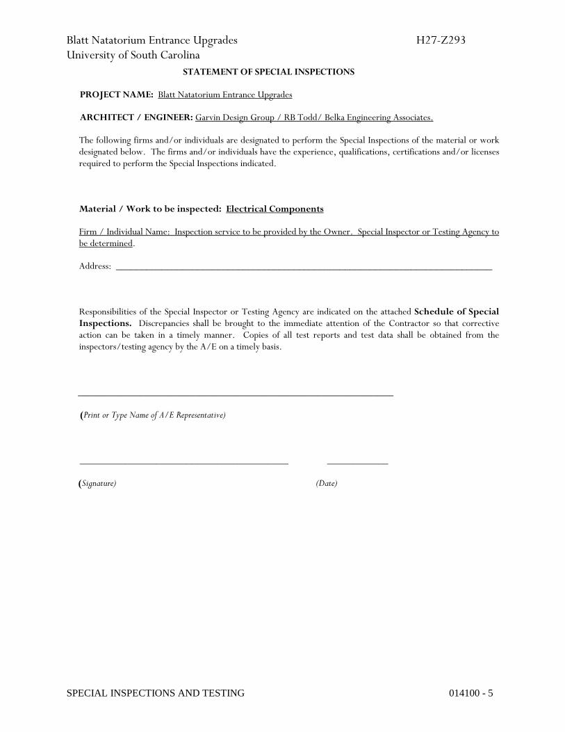
Blatt Natatorium Entrance Upgrades H27-Z293 University of South Carolina
SPECIAL INSPECTIONS AND TESTING 014100 - 5
STATEMENT OF SPECIAL INSPECTIONS
PROJECT NAME: Blatt Natatorium Entrance Upgrades
ARCHITECT / ENGINEER: Garvin Design Group / RB Todd/ Belka Engineering Associates.
The following firms and/or individuals are designated to perform the Special Inspections of the material or work designated below. The firms and/or individuals have the experience, qualifications, certifications and/or licenses required to perform the Special Inspections indicated.
Material / Work to be inspected: Electrical Components
Firm / Individual Name: Inspection service to be provided by the Owner. Special Inspector or Testing Agency to be determined.
Address: __________________________________________________________________________
Responsibilities of the Special Inspector or Testing Agency are indicated on the attached Schedule of Special Inspections. Discrepancies shall be brought to the immediate attention of the Contractor so that corrective action can be taken in a timely manner. Copies of all test reports and test data shall be obtained from the inspectors/testing agency by the A/E on a timely basis.
______________________________________________________________
(Print or Type Name of A/E Representative)
_________________________________________ ____________
(Signature) (Date)

Blatt Natatorium Entrance Upgrades H27-Z293 University of South Carolina
SPECIAL INSPECTIONS AND TESTING 014100 - 6
SCHEDULE OF SPECIAL INSPECTIONS
Project Name: Blatt Natatorium Entrance Upgrades.
Special Inspection requirements based on Section 1704 of Chapter 17 of the 2015 International Building Code and Chapter 1 of the 2015 International Building Code.
MATERIALS TYPE of INSPECTION and VERIFICATION
SPECIFICATION or CODE REFERENCE
INSPECTION BY:
Arch. Engr. Testing Agency or Special Inspector
Cast-in-place concrete
Periodic inspection of reinforcing steel placement
Spec. 033000
To be determined
Verify use of required Design Mix (Periodic)
Spec. 033000 To be determined
Continuous monitoring and sampling of concrete
Spec. 033000
To be determined
Continuous inspection of concrete placement
Spec. 033000 To be determined
Periodic inspection of curing techniques
Spec. 033000 To be determined
Masonry Periodic Verification
a) Proportions of site- prepared mortar
Spec. 042000 To be determined
b) Construction of mortar joints
Spec. 042000 To be determined
c) Location of reinforcement and connectors
Spec. 042000 To be determined
Masonry Periodic Inspection
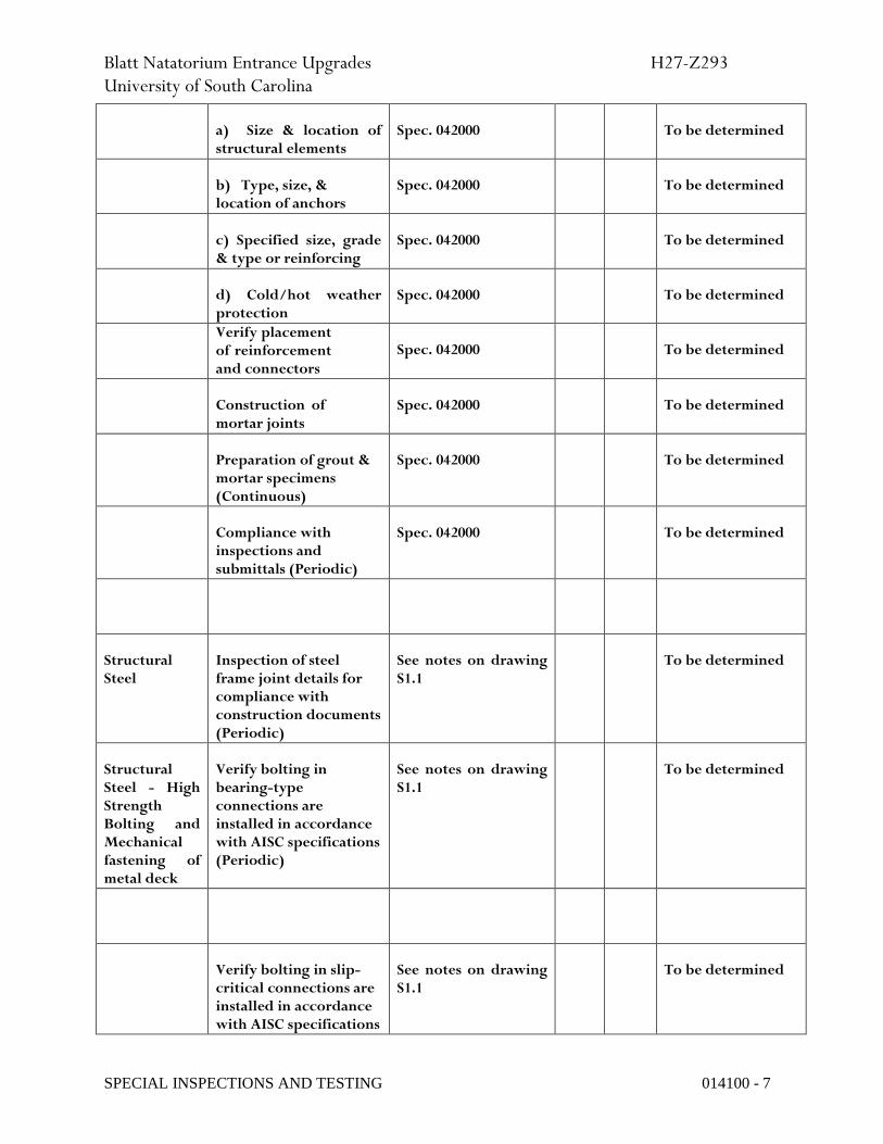
Blatt Natatorium Entrance Upgrades H27-Z293 University of South Carolina
SPECIAL INSPECTIONS AND TESTING 014100 - 7
a) Size & location of structural elements
Spec. 042000 To be determined
b) Type, size, & location of anchors
Spec. 042000 To be determined
c) Specified size, grade & type or reinforcing
Spec. 042000 To be determined
d) Cold/hot weather protection
Spec. 042000 To be determined
Verify placement of reinforcement and connectors
Spec. 042000 To be determined
Construction of mortar joints
Spec. 042000 To be determined
Preparation of grout & mortar specimens (Continuous)
Spec. 042000 To be determined
Compliance with inspections and submittals (Periodic)
Spec. 042000 To be determined
Structural Steel
Inspection of steel frame joint details for compliance with construction documents (Periodic)
See notes on drawing S1.1
To be determined
Structural Steel - High Strength Bolting and Mechanical fastening of metal deck
Verify bolting in bearing-type connections are installed in accordance with AISC specifications (Periodic)
See notes on drawing S1.1
To be determined
Verify bolting in slip-critical connections are installed in accordance with AISC specifications
See notes on drawing S1.1
To be determined

Blatt Natatorium Entrance Upgrades H27-Z293 University of South Carolina
SPECIAL INSPECTIONS AND TESTING 014100 - 8
(Continuous)
Verify identification marking on high-strength bolts, nuts and washers conforming to ASTM standards specified (Periodic)
See notes on drawing S1.1
To be determined
Verify fastener type and adherence to specified fastener attachment pattern (Periodic)
See notes on drawing S1.1
To be determined
Verify proper storage and handling of bolts, nuts, washers (Periodic)
See notes on drawing S1.1
To be determined
MATERIALS TYPE of INSPECTION and VERIFICATION
SPECIFICATION or CODE REFERENCE
INSPECTION BY:
Arch. Engr. Testing Agency or Special Inspector
Fire Resistance Penetration Inspections
Inspection of joint and penetration protection required by IBC 712 and IBC 713 before concealed from view
IBC 2015, 109.3.6 To be determined
MATERIALS TYPE of INSPECTION and VERIFICATION
SPECIFICATION or CODE REFERENCE
INSPECTION BY:
Arch. Engr. Testing Agency or Special Inspector
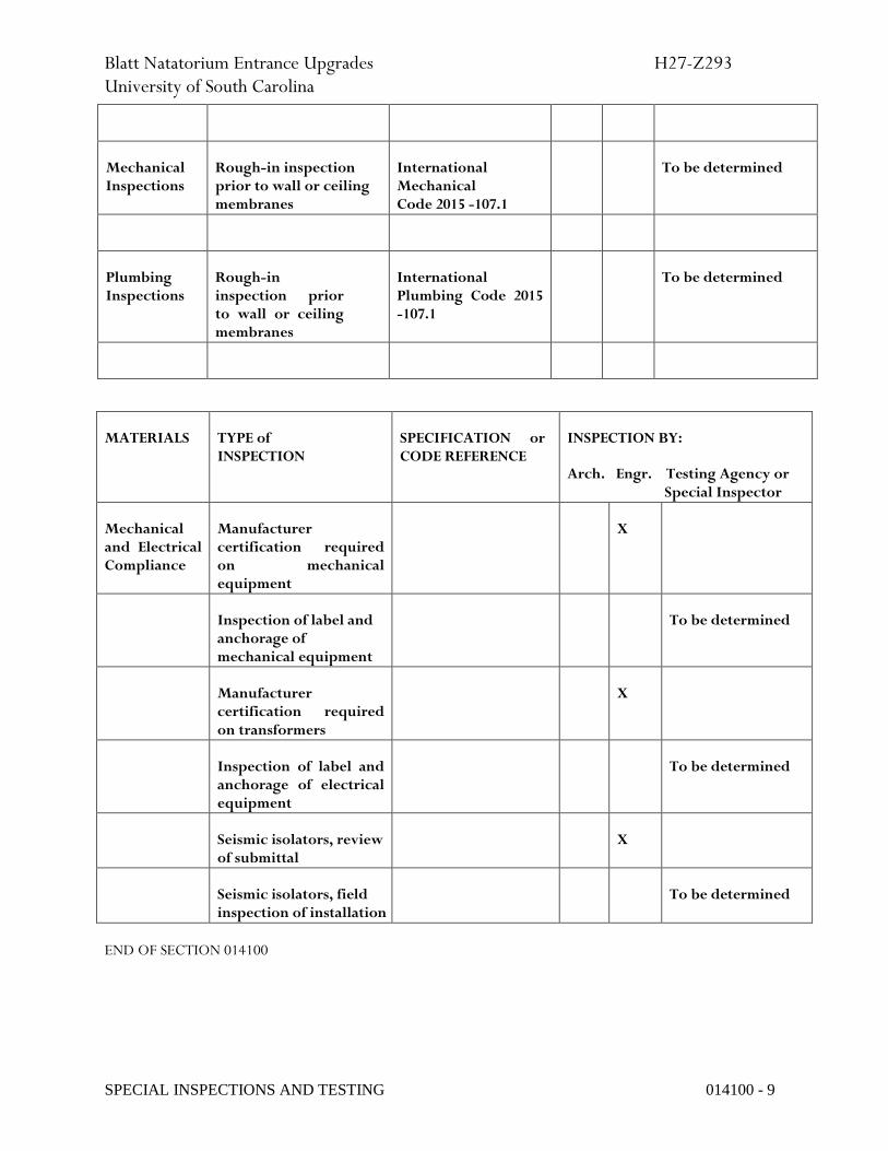
Blatt Natatorium Entrance Upgrades H27-Z293 University of South Carolina
SPECIAL INSPECTIONS AND TESTING 014100 - 9
Mechanical Inspections
Rough-in inspection prior to wall or ceiling membranes
International Mechanical Code 2015 -107.1
To be determined
Plumbing Inspections
Rough-in inspection prior to wall or ceiling membranes
International Plumbing Code 2015 -107.1
To be determined
END OF SECTION 014100
MATERIALS TYPE of INSPECTION
SPECIFICATION or CODE REFERENCE
INSPECTION BY:
Arch. Engr. Testing Agency or Special Inspector
Mechanical and Electrical Compliance
Manufacturer certification required on mechanical equipment
X
Inspection of label and anchorage of mechanical equipment
To be determined
Manufacturer certification required on transformers
X
Inspection of label and anchorage of electrical equipment
To be determined
Seismic isolators, review of submittal
X
Seismic isolators, field inspection of installation
To be determined
Blatt Natatorium Entrance Upgrades H27-Z293 University of South Carolina
REFERENCES 014200 - 1
SECTION 014200 - REFERENCES
PART 1 - GENERAL
1.1 RELATED DOCUMENTS
A. Drawings and general provisions of the Contract, including General and Supplementary Conditions and other Division 01 Specification Sections, apply to this Section.
1.2 DEFINITIONS
A. General: Basic Contract definitions are included in the Conditions of the Contract.
B. "Approved": When used to convey Architect's action on Contractor's submittals, applications, and requests, "approved" is limited to Architect's duties and responsibilities as stated in the Conditions of the Contract.
C. "Directed": A command or instruction by Architect. Other terms including "requested," "authorized," "selected," "required," and "permitted" have the same meaning as "directed."
D. "Indicated": Requirements expressed by graphic representations or in written form on Drawings, in Specifications, and in other Contract Documents. Other terms including "shown," "noted," "scheduled," and "specified" have the same meaning as "indicated."
E. "Regulations": Laws, ordinances, statutes, and lawful orders issued by authorities having jurisdiction, and rules, conventions, and agreements within the construction industry that control performance of the Work.
F. "Furnish": Supply and deliver to Project site, ready for unloading, unpacking, assembly, installation, and similar operations.
G. "Install": Operations at Project site including unloading, temporarily storing, unpacking, assembling, erecting, placing, anchoring, applying, working to dimension, finishing, curing, protecting, cleaning, and similar operations.
H. "Provide": Furnish and install, complete and ready for the intended use.
I. "Project Site": Space available for performing construction activities. The extent of Project site is shown on Drawings and may or may not be identical with the description of the land on which Project is to be built.
1.3 INDUSTRY STANDARDS
A. Applicability of Standards: Unless the Contract Documents include more stringent requirements, applicable construction industry standards have the same force and effect as if bound or copied directly into the Contract Documents to the extent referenced. Such standards are made a part of the Contract Documents by reference.

Blatt Natatorium Entrance Upgrades H27-Z293 University of South Carolina
REFERENCES 014200 - 2
B. Publication Dates: Comply with standards in effect as of date of the Contract Documents unless otherwise indicated.
C. Copies of Standards: Each entity engaged in construction on Project should be familiar with industry standards applicable to its construction activity. Copies of applicable standards are not bound with the Contract Documents.
1. Where copies of standards are needed to perform a required construction activity, obtain copies directly from publication source.
D. Abbreviations and Acronyms for Standards and Regulations: Where abbreviations and acronyms are used in Specifications or other Contract Documents, they shall mean the recognized name of the organizations responsible for the standards and regulations in the following list. Names, telephone numbers, and Web sites are subject to change and are believed to be accurate and up-to-date as of the date of the Contract Documents.
ADAAG Americans with Disabilities Act (ADA) (800) 872-2253 Architectural Barriers Act (ABA) (202) 272-0080 Accessibility Guidelines for Buildings and Facilities Available from Access Board www.access-board.gov CFR Code of Federal Regulations (866) 512-1800 Available from Government Printing Office (202) 512-1800 www.gpoaccess.gov/cfr/index.html DOD Department of Defense Military Specifications and Standards (215) 697-6257 Available from Department of Defense Single Stock Point http://dodssp.daps.dla.mil DSCC Defense Supply Center Columbus (See FS) FED-STD Federal Standard (See FS) FS Federal Specification (215) 697-6257 Available from Department of Defense Single Stock Point http://dodssp.daps.dla.mil Available from Defense Standardization Program www.dps.dla.mil Available from General Services Administration (202) 619-8925 www.gsa.gov Available from National Institute of Building Sciences (202) 289-7800 www.nibs.org FTMS Federal Test Method Standard (See FS)

Blatt Natatorium Entrance Upgrades H27-Z293 University of South Carolina
REFERENCES 014200 - 3
MIL (See MILSPEC) MIL-STD (See MILSPEC) MILSPEC Military Specification and Standards (215) 697-6257 Available from Department of Defense Single Stock Point http://dodssp.daps.dla.mil UFAS Uniform Federal Accessibility Standards (800) 872-2253 Available from Access Board (202) 272-0080 www.access-board.gov
1.4 ABBREVIATIONS AND ACRONYMS
A. Industry Organizations: Where abbreviations and acronyms are used in Specifications or other Contract Documents, they shall mean the recognized name of the entities indicated in Thomson Gale's "Encyclopedia of Associations" or in Columbia Books' "National Trade & Professional Associations of the U.S."
B. Industry Organizations: Where abbreviations and acronyms are used in Specifications or other Contract Documents, they shall mean the recognized name of the entities in the following list. Names, telephone numbers, and Web sites are subject to change and are believed to be accurate and up-to-date as of the date of the Contract Documents.
AA Aluminum Association, Inc. (The) (703) 358-2960 www.aluminum.org AAADM American Association of Automatic Door Manufacturers (216) 241-7333 www.aaadm.com AABC Associated Air Balance Council (202) 737-0202 www.aabchq.com AAMA American Architectural Manufacturers Association (847) 303-5664 www.aamanet.org AASHTO American Association of State Highway and (202) 624-5800 Transportation Officials www.transportation.org AATCC American Association of Textile Chemists and Colorists (The) (919) 549-8141 www.aatcc.org ABAA Air Barrier Association of America (866) 956-5888 www.airbarrier.org ABMA American Bearing Manufacturers Association (202) 367-1155 www.abma-dc.org
Blatt Natatorium Entrance Upgrades H27-Z293 University of South Carolina
REFERENCES 014200 - 4
ACI ACI International (248) 848-3700 (American Concrete Institute) www.aci-int.org ACPA American Concrete Pipe Association (972) 506-7216 www.concrete-pipe.org AEIC Association of Edison Illuminating Companies, Inc. (The) (205) 257-2530 www.aeic.org AF&PA American Forest & Paper Association (800) 878-8878 www.afandpa.org (202) 463-2700 AGA American Gas Association (202) 824-7000 www.aga.org AGC Associated General Contractors of America (The) (703) 548-3118 www.agc.org AHA American Hardboard Association (Now part of CPA) AHAM Association of Home Appliance Manufacturers (202) 872-5955 www.aham.org AI Asphalt Institute (859) 288-4960 www.asphaltinstitute.org AIA American Institute of Architects (The) (800) 242-3837 www.aia.org (202) 626-7300 AISC American Institute of Steel Construction (800) 644-2400 www.aisc.org (312) 670-2400 AISI American Iron and Steel Institute (202) 452-7100 www.steel.org AITC American Institute of Timber Construction (303) 792-9559 www.aitc-glulam.org ALCA Associated Landscape Contractors of America (Now PLANET - Professional Landcare Network) ALSC American Lumber Standard Committee, Incorporated (301) 972-1700 www.alsc.org AMCA Air Movement and Control Association International, Inc. (847) 394-0150 www.amca.org ANSI American National Standards Institute (202) 293-8020 www.ansi.org

Blatt Natatorium Entrance Upgrades H27-Z293 University of South Carolina
REFERENCES 014200 - 5
AOSA Association of Official Seed Analysts, Inc. (505) 522-1437 www.aosaseed.com APA APA - The Engineered Wood Association (253) 565-6600 www.apawood.org APA Architectural Precast Association (239) 454-6989 www.archprecast.org API American Petroleum Institute (202) 682-8000 www.api.org ARI Air-Conditioning & Refrigeration Institute (703) 524-8800 www.ari.org ARMA Asphalt Roofing Manufacturers Association (202) 207-0917 www.asphaltroofing.org ASCE American Society of Civil Engineers (800) 548-2723 www.asce.org (703) 295-6300 ASHRAE American Society of Heating, Refrigerating and (800) 527-4723 Air-Conditioning Engineers (404) 636-8400 www.ashrae.org ASME ASME International (800) 843-2763 (The American Society of Mechanical Engineers International) (973) 882-1170 www.asme.org ASSE American Society of Sanitary Engineering (440) 835-3040 www.asse-plumbing.org ASTM ASTM International (610) 832-9585 (American Society for Testing and Materials International) www.astm.org AWCI AWCI International (703) 534-8300 (Association of the Wall and Ceiling Industry International) www.awci.org AWCMA American Window Covering Manufacturers Association (Now WCSC) AWI Architectural Woodwork Institute (800) 449-8811 www.awinet.org (703) 733-0600 AWPA American Wood-Preservers' Association (334) 874-9800 www.awpa.com AWS American Welding Society (800) 443-9353

Blatt Natatorium Entrance Upgrades H27-Z293 University of South Carolina
REFERENCES 014200 - 6
www.aws.org (305) 443-9353 AWWA American Water Works Association (800) 926-7337 www.awwa.org (303) 794-7711 BHMA Builders Hardware Manufacturers Association (212) 297-2122 www.buildershardware.com BIA Brick Industry Association (The) (703) 620-0010 www.bia.org BICSI BICSI (800) 242-7405 www.bicsi.org (813) 979-1991 BIFMA BIFMA International (616) 285-3963 (Business and Institutional Furniture Manufacturer's Association International) www.bifma.com BISSC Baking Industry Sanitation Standards Committee (866) 342-4772 www.bissc.org CCC Carpet Cushion Council (203) 637-1312 www.carpetcushion.org CDA Copper Development Association (800) 232-3282 www.copper.org (212) 251-7200 CEA Canadian Electricity Association (613) 230-9263 www.canelect.ca CFFA Chemical Fabrics & Film Association, Inc. (216) 241-7333 www.chemicalfabricsandfilm.com CGA Compressed Gas Association (703) 788-2700 www.cganet.com CIMA Cellulose Insulation Manufacturers Association (888) 881-2462 www.cellulose.org (937) 222-2462 CISCA Ceilings & Interior Systems Construction Association (630) 584-1919 www.cisca.org CISPI Cast Iron Soil Pipe Institute (423) 892-0137 www.cispi.org CLFMI Chain Link Fence Manufacturers Institute (301) 596-2583 www.chainlinkinfo.org CPA Composite Panel Association (301) 670-0604 www.pbmdf.com

Blatt Natatorium Entrance Upgrades H27-Z293 University of South Carolina
REFERENCES 014200 - 7
CPPA Corrugated Polyethylene Pipe Association (800) 510-2772 www.cppa-info.org (202) 462-9607 CRI Carpet & Rug Institute (The) (800) 882-8846 www.carpet-rug.com (706) 278-3176 CRSI Concrete Reinforcing Steel Institute (847) 517-1200 www.crsi.org CSA CSA International (866) 797-4272 (Formerly: IAS - International Approval Services) (416) 747-4000 www.csa-international.org CSI Cast Stone Institute (770) 972-3011 www.caststone.org CSI Construction Specifications Institute (The) (800) 689-2900 www.csinet.org (703) 684-0300 CSSB Cedar Shake & Shingle Bureau (604) 820-7700 www.cedarbureau.org CTI Cooling Technology Institute (281) 583-4087 (Formerly: Cooling Tower Institute) www.cti.org DHI Door and Hardware Institute (703) 222-2010 www.dhi.org EIA Electronic Industries Alliance (703) 907-7500 www.eia.org EIMA EIFS Industry Members Association (800) 294-3462 www.eima.com (770) 968-7945 EJCDC Engineers Joint Contract Documents Committee (703) 295-5000 www.ejdc.org EJMA Expansion Joint Manufacturers Association, Inc. (914) 332-0040 www.ejma.org ESD ESD Association (315) 339-6937 www.esda.org FIBA Federation Internationale de Basketball Amateur 41 22 545 00 00 (The International Basketball Federation) www.fiba.com FIVB Federation Internationale de Volleyball 41 21 345 35 35 (The International Volleyball Federation)

Blatt Natatorium Entrance Upgrades H27-Z293 University of South Carolina
REFERENCES 014200 - 8
www.fivb.ch FMG FM Global (401) 275-3000 (Formerly: FM - Factory Mutual System) www.fmglobal.com FMRC Factory Mutual Research (Now FMG) FRSA Florida Roofing, Sheet Metal & Air Conditioning Contractors (407) 671-3772 Association, Inc. www.floridaroof.com FSA Fluid Sealing Association (610) 971-4850 www.fluidsealing.com FSC Forest Stewardship Council 49 228 367 66 0 www.fsc.org GA Gypsum Association (202) 289-5440 www.gypsum.org GANA Glass Association of North America (785) 271-0208 www.glasswebsite.com GRI (Now GSI) GS Green Seal (202) 872-6400 www.greenseal.org GSI Geosynthetic Institute (610) 522-8440 www.geosynthetic-institute.org HI Hydraulic Institute (888) 786-7744 www.pumps.org (973) 267-9700 HI Hydronics Institute (908) 464-8200 www.gamanet.org HMMA Hollow Metal Manufacturers Association (Part of NAAMM) HPVA Hardwood Plywood & Veneer Association (703) 435-2900 www.hpva.org HPW H. P. White Laboratory, Inc. (410) 838-6550 www.hpwhite.com IAS International Approval Services (Now CSA International)

Blatt Natatorium Entrance Upgrades H27-Z293 University of South Carolina
REFERENCES 014200 - 9
IBF International Badminton Federation (6-03) 9283-7155 www.intbadfed.org ICEA Insulated Cable Engineers Association, Inc. (770) 830-0369 www.icea.net ICRI International Concrete Repair Institute, Inc. (847) 827-0830 www.icri.org IEC International Electrotechnical Commission 41 22 919 02 11 www.iec.ch IEEE Institute of Electrical and Electronics Engineers, Inc. (The) (212) 419-7900 www.ieee.org IESNA Illuminating Engineering Society of North America (212) 248-5000 www.iesna.org IEST Institute of Environmental Sciences and Technology (847) 255-1561 www.iest.org IGCC Insulating Glass Certification Council (315) 646-2234 www.igcc.org IGMA Insulating Glass Manufacturers Alliance (613) 233-1510 www.igmaonline.org ILI Indiana Limestone Institute of America, Inc. (812) 275-4426 www.iliai.com ISO International Organization for Standardization 41 22 749 01 11 www.iso.ch Available from ANSI (202) 293-8020 www.ansi.org ISSFA International Solid Surface Fabricators Association (877) 464-7732 www.issfa.net (702) 567-8150 ITS Intertek (800) 345-3851 www.intertek.com (713) 407-3500 ITU International Telecommunication Union 41 22 730 51 11 www.itu.int/home KCMA Kitchen Cabinet Manufacturers Association (703) 264-1690 www.kcma.org LMA Laminating Materials Association (Now part of CPA)
Blatt Natatorium Entrance Upgrades H27-Z293 University of South Carolina
REFERENCES 014200 - 10
LPI Lightning Protection Institute (800) 488-6864 www.lightning.org (804) 314-8955 MBMA Metal Building Manufacturers Association (216) 241-7333 www.mbma.com MFMA Maple Flooring Manufacturers Association, Inc. (847) 480-9138 www.maplefloor.org MFMA Metal Framing Manufacturers Association (312) 644-6610 www.metalframingmfg.org MH Material Handling (Now MHIA) MHIA Material Handling Industry of America (800) 345-1815 www.mhia.org (704) 676-1190 MIA Marble Institute of America (440) 250-9222 www.marble-institute.com MPI Master Painters Institute (888) 674-8937 www.paintinfo.com MSS Manufacturers Standardization Society of The Valve and (703) 281-6613 Fittings Industry Inc. www.mss-hq.com NAAMM National Association of Architectural Metal Manufacturers (312) 332-0405 www.naamm.org NACE NACE International (800) 797-6623 (National Association of Corrosion Engineers International) (281) 228-6200 www.nace.org NADCA National Air Duct Cleaners Association (202) 737-2926 www.nadca.com NAGWS National Association for Girls and Women in Sport (800) 213-7193, ext.
453 www.aahperd.org/nagws/ NAIMA North American Insulation Manufacturers Association (703) 684-0084 www.naima.org NBGQA National Building Granite Quarries Association, Inc. (800) 557-2848 www.nbgqa.com NCAA National Collegiate Athletic Association (The) (317) 917-6222 www.ncaa.org

Blatt Natatorium Entrance Upgrades H27-Z293 University of South Carolina
REFERENCES 014200 - 11
NCMA National Concrete Masonry Association (703) 713-1900 www.ncma.org NCPI National Clay Pipe Institute (262) 248-9094 www.ncpi.org NCTA National Cable & Telecommunications Association (202) 775-3550 www.ncta.com NEBB National Environmental Balancing Bureau (301) 977-3698 www.nebb.org NECA National Electrical Contractors Association (301) 657-3110 www.necanet.org NeLMA Northeastern Lumber Manufacturers' Association (207) 829-6901 www.nelma.org NEMA National Electrical Manufacturers Association (703) 841-3200 www.nema.org NETA InterNational Electrical Testing Association (888) 300-6382 www.netaworld.org (303) 697-8441 NFHS National Federation of State High School Associations (317) 972-6900 www.nfhs.org NFPA NFPA (800) 344-3555 (National Fire Protection Association) (617) 770-3000 www.nfpa.org NFRC National Fenestration Rating Council (301) 589-1776 www.nfrc.org NGA National Glass Association (866) 342-5642 www.glass.org (703) 442-4890 NHLA National Hardwood Lumber Association (800) 933-0318 www.natlhardwood.org (901) 377-1818 NLGA National Lumber Grades Authority (604) 524-2393 www.nlga.org NOFMA NOFMA: The Wood Flooring Manufacturers Association (901) 526-5016 (Formerly: National Oak Flooring Manufacturers Association) www.nofma.org NRCA National Roofing Contractors Association (800) 323-9545 www.nrca.net (847) 299-9070 NRMCA National Ready Mixed Concrete Association (888) 846-7622

Blatt Natatorium Entrance Upgrades H27-Z293 University of South Carolina
REFERENCES 014200 - 12
www.nrmca.org (301) 587-1400 NSF NSF International (800) 673-6275 (National Sanitation Foundation International) (734) 769-8010 www.nsf.org NSSGA National Stone, Sand & Gravel Association (800) 342-1415 www.nssga.org (703) 525-8788 NTMA National Terrazzo & Mosaic Association, Inc. (The) (800) 323-9736 www.ntma.com (540) 751-0930 NTRMA National Tile Roofing Manufacturers Association (Now TRI) NWWDA National Wood Window and Door Association (Now WDMA) OPL Omega Point Laboratories, Inc. (Acquired by ITS - Intertek) (800) 966-5253 www.opl.com (210) 635-8100 PCI Precast/Prestressed Concrete Institute (312) 786-0300 www.pci.org PDCA Painting & Decorating Contractors of America (800) 332-7322 www.pdca.com (314) 514-7322 PDI Plumbing & Drainage Institute (800) 589-8956 www.pdionline.org (978) 557-0720 PGI PVC Geomembrane Institute (217) 333-3929 http://pgi-tp.ce.uiuc.edu PLANET Professional Landcare Network (800) 395-2522 (Formerly: ACLA - Associated Landscape Contractors of America) (703) 736-9666 www.landcarenetwork.org PTI Post-Tensioning Institute (602) 870-7540 www.post-tensioning.org RCSC Research Council on Structural Connections (800) 644-2400 www.boltcouncil.org (312) 670-2400 RFCI Resilient Floor Covering Institute (301) 340-8580 www.rfci.com RIS Redwood Inspection Service (888) 225-7339 www.calredwood.org (415) 382-0662 RTI (Formerly: NTRMA - National Tile Roofing Manufacturers Association)

Blatt Natatorium Entrance Upgrades H27-Z293 University of South Carolina
REFERENCES 014200 - 13
(Now TRI) SAE SAE International (877) 606-7323 www.sae.org (724) 776-4841 SDI Steel Deck Institute (847) 458-4647 www.sdi.org SDI Steel Door Institute (440) 899-0010 www.steeldoor.org SEFA Scientific Equipment and Furniture Association (516) 294-5424 www.sefalabs.com SGCC Safety Glazing Certification Council (315) 646-2234 www.sgcc.org SIA Security Industry Association (703) 683-2075 www.siaonline.org SIGMA Sealed Insulating Glass Manufacturers Association (Now IGMA) SJI Steel Joist Institute (843) 626-1995 www.steeljoist.org SMA Screen Manufacturers Association (561) 533-0991 www.smacentral.org SMACNA Sheet Metal and Air Conditioning Contractors' (703) 803-2980 National Association www.smacna.org SMPTE Society of Motion Picture and Television Engineers (914) 761-1100 www.smpte.org SPFA Spray Polyurethane Foam Alliance (800) 523-6154 (Formerly: SPI/SPFD - The Society of the Plastics Industry, Inc.; Spray Polyurethane Foam Division) www.sprayfoam.org SPIB Southern Pine Inspection Bureau (The) (850) 434-2611 www.spib.org SPRI Single Ply Roofing Industry (781) 647-7026 www.spri.org SSINA Specialty Steel Industry of North America (800) 982-0355 www.ssina.com (202) 342-8630 SSPC SSPC: The Society for Protective Coatings (877) 281-7772
Blatt Natatorium Entrance Upgrades H27-Z293 University of South Carolina
REFERENCES 014200 - 14
www.sspc.org (412) 281-2331 STI Steel Tank Institute (847) 438-8265 www.steeltank.com SWI Steel Window Institute (216) 241-7333 www.steelwindows.com SWRI Sealant, Waterproofing, & Restoration Institute (816) 472-7974 www.swrionline.org TCA Tile Council of America, Inc. (864) 646-8453 www.tileusa.com TIA/EIA Telecommunications Industry Association/Electronic (703) 907-7700 Industries Alliance www.tiaonline.org TMS The Masonry Society (303) 939-9700 www.masonrysociety.org TPI Truss Plate Institute, Inc. (703) 683-1010 www.tpinst.org TPI Turfgrass Producers International (847) 649-5555 www.turfgrasssod.org TRI Tile Roofing Institute (312) 670-4177 (Formerly: RTI - Roof Tile Institute) www.tileroofing.org UL Underwriters Laboratories Inc. (877) 854-3577 www.ul.com (847) 272-8800 UNI Uni-Bell PVC Pipe Association (972) 243-3902 www.uni-bell.org USAV USA Volleyball (888) 786-5539 www.usavolleyball.org (719) 228-6800 USGBC U.S. Green Building Council (202) 828-7422 www.usgbc.org USITT United States Institute for Theatre Technology, Inc. (800) 938-7488 www.usitt.org (315) 463-6463 WASTEC Waste Equipment Technology Association (800) 424-2869 www.wastec.org (202) 244-4700 WCLIB West Coast Lumber Inspection Bureau (800) 283-1486 www.wclib.org (503) 639-0651
Blatt Natatorium Entrance Upgrades H27-Z293 University of South Carolina
REFERENCES 014200 - 15
WCMA Window Covering Manufacturers Association (Now WCSC) WCSC Window Covering Safety Council (800) 506-4636 (Formerly: WCMA - Window Covering Manufacturers (212) 297-2109 Association) www.windowcoverings.org WDMA Window & Door Manufacturers Association (800) 223-2301 (Formerly: NWWDA - National Wood Window and (847) 299-5200 Door Association) www.wdma.com WI Woodwork Institute (Formerly: WIC - Woodwork Institute of (916) 372-9943 California) www.wicnet.org WIC Woodwork Institute of California (Now WI) WMMPA Wood Moulding & Millwork Producers Association (800) 550-7889 www.wmmpa.com (530) 661-9591 WSRCA Western States Roofing Contractors Association (800) 725-0333 www.wsrca.com (650) 570-5441 WWPA Western Wood Products Association (503) 224-3930 www.wwpa.org
C. Code Agencies: Where abbreviations and acronyms are used in Specifications or other Contract Documents, they shall mean the recognized name of the entities in the following list. Names, telephone numbers, and Web sites are subject to change and are believed to be accurate and up-to-date as of the date of the Contract Documents.
BOCA BOCA International, Inc. (See ICC) IAPMO International Association of Plumbing and Mechanical Officials (909) 472-4100 www.iapmo.org ICBO International Conference of Building Officials (See ICC) ICBO ES ICBO Evaluation Service, Inc. (See ICC-ES) ICC International Code Council (888) 422-7233 www.iccsafe.org (703) 931-4533 ICC-ES ICC Evaluation Service, Inc. (800) 423-6587
Blatt Natatorium Entrance Upgrades H27-Z293 University of South Carolina
REFERENCES 014200 - 16
www.icc-es.org (562) 699-0543 SBCCI Southern Building Code Congress International, Inc. (See ICC)
D. Federal Government Agencies: Where abbreviations and acronyms are used in Specifications or other Contract Documents, they shall mean the recognized name of the entities in the following list. Names, telephone numbers, and Web sites are subject to change and are believed to be accurate and up-to-date as of the date of the Contract Documents.
CE Army Corps of Engineers www.usace.army.mil CPSC Consumer Product Safety Commission (800) 638-2772 www.cpsc.gov (301) 504-7923 DOC Department of Commerce (202) 482-2000 www.commerce.gov DOD Department of Defense (215) 697-6257 http://.dodssp.daps.dla.mil DOE Department of Energy (202) 586-9220 www.energy.gov EPA Environmental Protection Agency (202) 272-0167 www.epa.gov FAA Federal Aviation Administration (866) 835-5322 www.faa.gov FCC Federal Communications Commission (888) 225-5322 www.fcc.gov FDA Food and Drug Administration (888) 463-6332 www.fda.gov GSA General Services Administration (800) 488-3111 www.gsa.gov HUD Department of Housing and Urban Development (202) 708-1112 www.hud.gov LBL Lawrence Berkeley National Laboratory (510) 486-4000 www.lbl.gov NCHRP National Cooperative Highway Research Program (See TRB) NIST National Institute of Standards and Technology (301) 975-6478 www.nist.gov

Blatt Natatorium Entrance Upgrades H27-Z293 University of South Carolina
REFERENCES 014200 - 17
OSHA Occupational Safety & Health Administration (800) 321-6742 www.osha.gov (202) 693-1999 PBS Public Building Service (See GSA) PHS Office of Public Health and Science (202) 690-7694 www.osophs.dhhs.gov/ophs RUS Rural Utilities Service (202) 720-9540 (See USDA) SD State Department (202) 647-4000 www.state.gov TRB Transportation Research Board (202) 334-2934 www.nas.edu/trb USDA Department of Agriculture (202) 720-2791 www.usda.gov USPS Postal Service (202) 268-2000 www.usps.com
E. State Government Agencies: Where abbreviations and acronyms are used in Specifications or other Contract Documents, they shall mean the recognized name of the entities in the following list. Names, telephone numbers, and Web sites are subject to change and are believed to be accurate and up-to-date as of the date of the Contract Documents.
CBHF State of California, Department of Consumer Affairs (800) 952-5210 Bureau of Home Furnishings and Thermal Insulation (916) 574-2041 www.dca.ca.gov/bhfti CPUC California Public Utilities Commission (415) 703-2782 www.cpuc.ca.gov TFS Texas Forest Service (936) 639-8180 Forest Resource Development http://txforestservice.tamu.edu
PART 2 - PRODUCTS (Not Used)
PART 3 - EXECUTION (Not Used)
END OF SECTION 014200

Blatt Natatorium Entrance Upgrades H27-Z293 University of South Carolina
TEMPORARY FACILITIES AND CONTROLS 015000 - 1
SECTION 015000 - TEMPORARY FACILITIES AND CONTROLS
PART 1 - GENERAL
1.1 RELATED DOCUMENTS
A. Drawings and general provisions of the Contract, including General and Supplementary Conditions and other Division 01 Specification Sections, apply to this Section.
1.2 SUMMARY
A. This Section includes requirements for temporary utilities, support facilities, and security and protection facilities.
B. Related Sections include the following:
1. Division 01 Section "Summary" for limitations on utility interruptions and other work restrictions. 2. Division 01 Section "Submittal Procedures" for procedures for submitting copies of
implementation and termination schedule and utility reports. 3. Division 01 Section "Execution Requirements" for progress cleaning requirements. 4. Divisions 02 through 33 Sections for temporary heat, ventilation, and humidity requirements for
products in those Sections.
1.3 USE CHARGES
A. Water and Sewer Service from Existing System: Water from Owner's existing water system is available for use without metering and without payment of use charges. Provide connections and extensions of services as required for construction operations.
B. Electric Power Service from Existing System: Electric power from Owner's existing system is available for use without metering and without payment of use charges. Provide connections and extensions of services as required for construction operations.
1.4 SUBMITTALS
A. Site Plan: Show temporary facilities, staging areas, and parking areas for construction personnel.
1.5 PROJECT CONDITIONS
A. Temporary Use of Permanent Facilities: Installer of each permanent service shall assume responsibility for operation, maintenance, and protection of each permanent service during its use as a construction facility before Owner's acceptance, regardless of previously assigned responsibilities.
Blatt Natatorium Entrance Upgrades H27-Z293 University of South Carolina
TEMPORARY FACILITIES AND CONTROLS 015000 - 2
PART 2 - PRODUCTS
2.1 EQUIPMENT
A. Fire Extinguishers: Portable, UL rated; with class and extinguishing agent as required by locations and classes of fire exposures.
PART 3 - EXECUTION
3.1 INSTALLATION, GENERAL
A. Locate facilities where they will serve Project adequately and result in minimum interference with performance of the Work. Relocate and modify facilities as required by progress of the Work.
B. Provide each facility ready for use when needed to avoid delay. Do not remove until facilities are no longer needed or are replaced by authorized use of completed permanent facilities.
3.2 TEMPORARY UTILITY INSTALLATION
A. Water Service: Use of Owner's existing water service facilities will be permitted, as long as facilities are cleaned and maintained in a condition acceptable to Owner. At Substantial Completion, restore these facilities to condition existing before initial use.
1. Where installations below an outlet might be damaged by spillage or leakage, provide a drip pan of suitable size to minimize water damage. Drain accumulated water promptly from pans.
B. Sanitary Facilities: Provide temporary toilets, wash facilities, and drinking water for use of construction personnel. Comply with authorities having jurisdiction for type, number, location, operation, and maintenance of fixtures and facilities.
C. Heating and Cooling: Provide temporary heating and cooling required by construction activities for curing or drying of completed installations or for protecting installed construction from adverse effects of low temperatures or high humidity. Select equipment that will not have a harmful effect on completed installations or elements being installed.
D. Ventilation and Humidity Control: Provide temporary ventilation required by construction activities for curing or drying of completed installations or for protecting installed construction from adverse effects of high humidity. Select equipment that will not have a harmful effect on completed installations or elements being installed. Coordinate ventilation requirements to produce ambient condition required and minimize energy consumption.
E. Lighting: Provide temporary lighting with local switching that provides adequate illumination for construction operations, observations, inspections, and traffic conditions.
1. Install and operate temporary lighting that fulfills security and protection requirements without operating entire system.
F. Lifts and Hoists: Provide facilities necessary for hoisting materials and personnel.

Blatt Natatorium Entrance Upgrades H27-Z293 University of South Carolina
TEMPORARY FACILITIES AND CONTROLS 015000 - 3
3.3 SECURITY AND PROTECTION FACILITIES INSTALLATION
A. Barricades, Warning Signs, and Lights: Comply with requirements of authorities having jurisdiction for erecting structurally adequate barricades, including warning signs and lighting.
B. Temporary Fire Protection: Install and maintain temporary fire-protection facilities of types needed to protect against reasonably predictable and controllable fire losses. Comply with NFPA 241.
1. Prohibit smoking in construction areas. 2. Supervise welding operations, combustion-type temporary heating units, and similar sources of fire
ignition according to requirements of authorities having jurisdiction. 3. Develop and supervise an overall fire-prevention and -protection program for personnel at Project
site. Review needs with local fire department and establish procedures to be followed. Instruct personnel in methods and procedures. Post warnings and information.
END OF SECTION 015000
Blatt Natatorium Entrance Upgrades H27-Z293 University of South Carolina
PRODUCT REQUIREMENTS 016000 - 1
SECTION 016000 - PRODUCT REQUIREMENTS
PART 1 - GENERAL
1.1 RELATED DOCUMENTS
A. Drawings and general provisions of the Contract, including General and Supplementary Conditions and other Division 01 Specification Sections, apply to this Section.
1.2 SUMMARY
A. This Section includes administrative and procedural requirements for selection of products for use in Project; product delivery, storage, and handling; manufacturers' standard warranties on products; special warranties; product substitutions; and comparable products.
B. Related Sections include the following: 1. Division 01 Section "References" for applicable industry standards for products specified. 2. Division 01 Section "Closeout Procedures" for submitting warranties for Contract closeout. 3. Divisions 02 through 33 Sections for specific requirements for warranties on products and
installations specified to be warranted.
1.3 DEFINITIONS
A. Products: Items purchased for incorporating into the Work, whether purchased for Project or taken from previously purchased stock. The term "product" includes the terms "material," "equipment," "system," and terms of similar intent.
1. Named Products: Items identified by manufacturer's product name, including make or model number or other designation shown or listed in manufacturer's published product literature, that is current as of date of the Contract Documents.
2. New Products: Items that have not previously been incorporated into another project or facility, except that products consisting of recycled-content materials are allowed, unless explicitly stated otherwise. Products salvaged or recycled from other projects are not considered new products.
3. Comparable Product: Product that is demonstrated and approved through submittal process, or where indicated as a product substitution, to have the indicated qualities related to type, function, dimension, in-service performance, physical properties, appearance, and other characteristics that equal or exceed those of specified product.
B. Substitutions: Changes in products, materials, equipment, and methods of construction from those required by the Contract Documents and proposed by Contractor.
C. Basis-of-Design Product Specification: Where a specific manufacturer's product is named and accompanied by the words "basis of design," including make or model number or other designation, to establish the significant qualities related to type, function, dimension, in-service performance, physical properties, appearance, and other characteristics for purposes of evaluating comparable products of other named manufacturers.
Blatt Natatorium Entrance Upgrades H27-Z293 University of South Carolina
PRODUCT REQUIREMENTS 016000 - 2
1.4 SUBMITTALS
A. Product List: Submit a list, in tabular from, showing specified products. Include generic names of products required. Include manufacturer's name and proprietary product names for each product.
1. Coordinate product list with Contractor's Construction Schedule and the Submittals Schedule. 2. Form: Tabulate information for each product under the following column headings:
a. Specification Section number and title. b. Generic name used in the Contract Documents. c. Proprietary name, model number, and similar designations. d. Manufacturer's name and address. e. Supplier's name and address. f. Installer's name and address. g. Projected delivery date or time span of delivery period. h. Identification of items that require early submittal approval for scheduled delivery date.
3. Initial Submittal: Within 30 days after date of commencement of the Work, submit 3 Insert number copies of initial product list. Include a written explanation for omissions of data and for variations from Contract requirements.
a. At Contractor's option, initial submittal may be limited to product selections and designations that must be established early in Contract period.
4. Completed List: Within 60 days after date of commencement of the Work, submit 3 copies of completed product list. Include a written explanation for omissions of data and for variations from Contract requirements.
5. Architect's Action: Architect will respond in writing to Contractor within 15 days of receipt of completed product list. Architect's response will include a list of unacceptable product selections and a brief explanation of reasons for this action. Architect's response, or lack of response, does not constitute a waiver of requirement to comply with the Contract Documents.
B. Substitution Requests: Submit three copies of each request for consideration. Identify product or fabrication or installation method to be replaced. Include Specification Section number and title and Drawing numbers and titles.
1. Substitution Request Form: Use CSI Form 13.1A. 2. Documentation: Show compliance with requirements for substitutions and the following, as
applicable:
a. Statement indicating why specified material or product cannot be provided. b. Coordination information, including a list of changes or modifications needed to other parts
of the Work and to construction performed by Owner and separate contractors, that will be necessary to accommodate proposed substitution.
c. Detailed comparison of significant qualities of proposed substitution with those of the Work specified. Significant qualities may include attributes such as performance, weight, size, durability, visual effect, and specific features and requirements indicated.
d. Product Data, including drawings and descriptions of products and fabrication and installation procedures.
e. Samples, where applicable or requested.

Blatt Natatorium Entrance Upgrades H27-Z293 University of South Carolina
PRODUCT REQUIREMENTS 016000 - 3
f. List of similar installations for completed projects with project names and addresses and names and addresses of architects and owners.
g. Material test reports from a qualified testing agency indicating and interpreting test results for compliance with requirements indicated.
h. Research/evaluation reports evidencing compliance with building code in effect for Project, from a model code organization acceptable to authorities having jurisdiction.
i. Detailed comparison of Contractor's Construction Schedule using proposed substitution with products specified for the Work, including effect on the overall Contract Time. If specified product or method of construction cannot be provided within the Contract Time, include letter from manufacturer, on manufacturer's letterhead, stating lack of availability or delays in delivery.
j. Cost information, including a proposal of change, if any, in the Contract Sum. k. Contractor's certification that proposed substitution complies with requirements in the
Contract Documents and is appropriate for applications indicated. l. Contractor's waiver of rights to additional payment or time that may subsequently become
necessary because of failure of proposed substitution to produce indicated results.
3. Architect's Action: If necessary, Architect will request additional information or documentation for evaluation within 7 days of receipt of a request for substitution. Architect will notify Contractor of acceptance or rejection of proposed substitution within 15 days of receipt of request, or 7 days of receipt of additional information or documentation, whichever is later.
a. Form of Acceptance: Change Order. b. Use product specified if Architect cannot make a decision on use of a proposed substitution
within time allocated.
C. Comparable Product Requests: Submit three copies of each request for consideration. Identify product or fabrication or installation method to be replaced. Include Specification Section number and title and Drawing numbers and titles.
1. Architect's Action: If necessary, Architect will request additional information or documentation for evaluation within one week of receipt of a comparable product request. Architect will notify Contractor of approval or rejection of proposed comparable product request within 15 days of receipt of request, or 7 days of receipt of additional information or documentation, whichever is later.
a. Form of Approval: As specified in Division 01 Section "Submittal Procedures." b. Use product specified if Architect cannot make a decision on use of a comparable product
request within time allocated.
D. Basis-of-Design Product Specification Submittal: Comply with requirements in Division 01 Section "Submittal Procedures." Show compliance with requirements.
1.5 QUALITY ASSURANCE
A. Compatibility of Options: If Contractor is given option of selecting between two or more products for use on Project, product selected shall be compatible with products previously selected, even if previously selected products were also options.
Blatt Natatorium Entrance Upgrades H27-Z293 University of South Carolina
PRODUCT REQUIREMENTS 016000 - 4
1. Each contractor is responsible for providing products and construction methods compatible with products and construction methods of other contractors.
2. If a dispute arises between contractors over concurrently selectable but incompatible products, Architect will determine which products shall be used.
1.6 PRODUCT DELIVERY, STORAGE, AND HANDLING
A. Deliver, store, and handle products using means and methods that will prevent damage, deterioration, and loss, including theft. Comply with manufacturer's written instructions.
B. Delivery and Handling:
1. Schedule delivery to minimize long-term storage at Project site and to prevent overcrowding of construction spaces.
2. Coordinate delivery with installation time to ensure minimum holding time for items that are flammable, hazardous, easily damaged, or sensitive to deterioration, theft, and other losses.
3. Deliver products to Project site in an undamaged condition in manufacturer's original sealed container or other packaging system, complete with labels and instructions for handling, storing, unpacking, protecting, and installing.
4. Inspect products on delivery to ensure compliance with the Contract Documents and to ensure that products are undamaged and properly protected.
C. Storage:
1. Store products to allow for inspection and measurement of quantity or counting of units. 2. Store materials in a manner that will not endanger Project structure. 3. Store products that are subject to damage by the elements, under cover in a weathertight enclosure
above ground, with ventilation adequate to prevent condensation. 4. Store cementitious products and materials on elevated platforms. 5. Store foam plastic from exposure to sunlight, except to extent necessary for period of installation
and concealment. 6. Comply with product manufacturer's written instructions for temperature, humidity, ventilation,
and weather-protection requirements for storage. 7. Protect stored products from damage and liquids from freezing. 8. Provide a secure location and enclosure at Project site for storage of materials and equipment by
Owner's construction forces. Coordinate location with Owner.
1.7 PRODUCT WARRANTIES
A. Warranties specified in other Sections shall be in addition to, and run concurrent with, other warranties required by the Contract Documents. Manufacturer's disclaimers and limitations on product warranties do not relieve Contractor of obligations under requirements of the Contract Documents.
1. Manufacturer's Warranty: Preprinted written warranty published by individual manufacturer for a particular product and specifically endorsed by manufacturer to Owner.
2. Special Warranty: Written warranty required by or incorporated into the Contract Documents, either to extend time limit provided by manufacturer's warranty or to provide more rights for Owner.

Blatt Natatorium Entrance Upgrades H27-Z293 University of South Carolina
PRODUCT REQUIREMENTS 016000 - 5
B. Special Warranties: Prepare a written document that contains appropriate terms and identification, ready for execution. Submit a draft for approval before final execution.
1. Manufacturer's Standard Form: Modified to include Project-specific information and properly executed.
2. Specified Form: When specified forms are included with the Specifications, prepare a written document using appropriate form properly executed.
3. Refer to Divisions 02 through 33 Sections for specific content requirements and particular requirements for submitting special warranties.
C. Submittal Time: Comply with requirements in Division 01 Section "Closeout Procedures."
PART 2 - PRODUCTS
2.1 PRODUCT SELECTION PROCEDURES
A. General Product Requirements: Provide products that comply with the Contract Documents, that are undamaged and, unless otherwise indicated, that are new at time of installation.
1. Provide products complete with accessories, trim, finish, fasteners, and other items needed for a complete installation and indicated use and effect.
2. Standard Products: If available, and unless custom products or nonstandard options are specified, provide standard products of types that have been produced and used successfully in similar situations on other projects.
3. Owner reserves the right to limit selection to products with warranties not in conflict with requirements of the Contract Documents.
4. Where products are accompanied by the term "as selected," Architect will make selection. 5. Where products are accompanied by the term "match sample," sample to be matched is
Architect's. 6. Descriptive, performance, and reference standard requirements in the Specifications establish
"salient characteristics" of products. 7. Or Equal: Where products are specified by name and accompanied by the term "or equal" or "or
approved equal" or "or approved," comply with provisions in Part 2 "Comparable Products" Article to obtain approval for use of an unnamed product.
B. Product Selection Procedures:
1. Product: Where Specifications name a single product and manufacturer, provide the named product that complies with requirements.
2. Manufacturer/Source: Where Specifications name a single manufacturer or source, provide a product by the named manufacturer or source that complies with requirements.
3. Products: Where Specifications include a list of names of both products and manufacturers, provide one of the products listed that complies with requirements.
4. Manufacturers: Where Specifications include a list of manufacturers' names, provide a product by one of the manufacturers listed that complies with requirements.
5. Available Products: Where Specifications include a list of names of both products and manufacturers, provide one of the products listed, or an unnamed product, that complies with requirements. Comply with provisions in Part 2 "Comparable Products" Article for consideration of an unnamed product.

Blatt Natatorium Entrance Upgrades H27-Z293 University of South Carolina
PRODUCT REQUIREMENTS 016000 - 6
6. Available Manufacturers: Where Specifications include a list of manufacturers, provide a product by one of the manufacturers listed, or an unnamed manufacturer, that complies with requirements. Comply with provisions in Part 2 "Comparable Products" Article for consideration of an unnamed product.
7. Product Options: Where Specifications indicate that sizes, profiles, and dimensional requirements on Drawings are based on a specific product or system, provide the specified product or system. Comply with provisions in Part 2 "Product Substitutions" Article for consideration of an unnamed product or system.
8. Basis-of-Design Product: Where Specifications name a product and include a list of manufacturers, provide the specified product or a comparable product by one of the other named manufacturers. Drawings and Specifications indicate sizes, profiles, dimensions, and other characteristics that are based on the product named. Comply with provisions in Part 2 "Comparable Products" Article for consideration of an unnamed product by the other named manufacturers.
9. Visual Matching Specification: Where Specifications require matching an established Sample, select a product that complies with requirements and matches Architect's sample. Architect's decision will be final on whether a proposed product matches.
a. If no product available within specified category matches and complies with other specified requirements, comply with provisions in Part 2 "Product Substitutions" Article for proposal of product.
10. Visual Selection Specification: Where Specifications include the phrase "as selected from manufacturer's colors, patterns, textures" or a similar phrase, select a product that complies with other specified requirements.
a. Standard Range: Where Specifications include the phrase "standard range of colors, patterns, textures" or similar phrase, Architect will select color, pattern, density, or texture from manufacturer's product line that does not include premium items.
b. Full Range: Where Specifications include the phrase "full range of colors, patterns, textures" or similar phrase, Architect will select color, pattern, density, or texture from manufacturer's product line that includes both standard and premium items.
2.2 PRODUCT SUBSTITUTIONS
A. Timing: Architect will consider requests for substitution if received within 60 days after commencement of the Work. Requests received after that time may be considered or rejected at discretion of Architect.
B. Conditions: Architect will consider Contractor's request for substitution when the following conditions are satisfied. If the following conditions are not satisfied, Architect will return requests without action, except to record noncompliance with these requirements:
1. Requested substitution offers Owner a substantial advantage in cost, time, energy conservation, or other considerations, after deducting additional responsibilities Owner must assume. Owner's additional responsibilities may include compensation to Architect for redesign and evaluation services, increased cost of other construction by Owner, and similar considerations.
2. Requested substitution does not require extensive revisions to the Contract Documents. 3. Requested substitution is consistent with the Contract Documents and will produce indicated
results. 4. Substitution request is fully documented and properly submitted. 5. Requested substitution will not adversely affect Contractor's Construction Schedule.

Blatt Natatorium Entrance Upgrades H27-Z293 University of South Carolina
PRODUCT REQUIREMENTS 016000 - 7
6. Requested substitution has received necessary approvals of authorities having jurisdiction. 7. Requested substitution is compatible with other portions of the Work. 8. Requested substitution has been coordinated with other portions of the Work. 9. Requested substitution provides specified warranty. 10. If requested substitution involves more than one contractor, requested substitution has been
coordinated with other portions of the Work, is uniform and consistent, is compatible with other products, and is acceptable to all contractors involved.
2.3 COMPARABLE PRODUCTS
A. Conditions: Architect will consider Contractor's request for comparable product when the following conditions are satisfied. If the following conditions are not satisfied, Architect will return requests without action, except to record noncompliance with these requirements:
1. Evidence that the proposed product does not require extensive revisions to the Contract Documents, that it is consistent with the Contract Documents and will produce the indicated results, and that it is compatible with other portions of the Work.
2. Detailed comparison of significant qualities of proposed product with those named in the Specifications. Significant qualities include attributes such as performance, weight, size, durability, visual effect, and specific features and requirements indicated.
3. Evidence that proposed product provides specified warranty. 4. List of similar installations for completed projects with project names and addresses and names and
addresses of architects and owners, if requested. 5. Samples, if requested.
PART 3 - EXECUTION (Not Used)
END OF SECTION 016000

Blatt Natatorium Entrance Upgrades H27-Z293 University of South Carolina
EXECUTION REQUIREMENTS 017000 - 1
SECTION 017000 – EXECUTION REQUIREMENTS
PART 1 - GENERAL
1.1 RELATED DOCUMENTS
A. Drawings and general provisions of the Contract, including General and Supplementary Conditions and other Division 01 Specification Sections, apply to this Section.
1.2 SUMMARY
A. This Section includes general procedural requirements governing execution of the Work including, but not limited to, the following:
1. Construction layout. 2. Field engineering and surveying. 3. General installation of products. 4. Coordination of Owner-installed products. 5. Progress cleaning. 6. Starting and adjusting. 7. Protection of installed construction. 8. Correction of the Work.
B. Related Sections include the following:
1. Division 01 Section "Project Management and Coordination" for procedures for coordinating field engineering with other construction activities.
2. Division 01 Section "Submittal Procedures" for submitting surveys. 3. Division 01 Section "Closeout Procedures" for submitting final property survey with Project
Record Documents, recording of Owner-accepted deviations from indicated lines and levels, and final cleaning.
1.3 SUBMITTALS
A. Qualification Data: For professional engineer.
B. Certificates: Submit certificate signed by professional engineer certifying that location and elevation of improvements comply with requirements.
C. Certified Surveys: Submit two copies signed by professional engineer.
D. Final Property Survey: Submit 3 copies showing the Work performed and record survey data.
Blatt Natatorium Entrance Upgrades H27-Z293 University of South Carolina
EXECUTION REQUIREMENTS 017000 - 2
1.4 QUALITY ASSURANCE
A. Land Surveyor Qualifications: A professional engineer who is legally qualified to practice in jurisdiction where Project is located and who is experienced in providing land-surveying services of the kind indicated.
PART 2 - PRODUCTS (Not Used)
PART 3 - EXECUTION
3.1 EXAMINATION
A. Existing Conditions: The existence and location of site improvements, utilities, and other construction indicated as existing are not guaranteed. Before beginning work, investigate and verify the existence and location of mechanical and electrical systems and other construction affecting the Work.
1. Before construction, verify the location and points of connection of utility services.
B. Existing Utilities: The existence and location of underground and other utilities and construction indicated as existing are not guaranteed. Before beginning sitework, investigate and verify the existence and location of underground utilities and other construction affecting the Work.
1. Before construction, verify the location and invert elevation at points of connection of sanitary sewer, storm sewer, and water-service piping; and underground electrical services.
2. Furnish location data for work related to Project that must be performed by public utilities serving Project site.
C. Acceptance of Conditions: Examine substrates, areas, and conditions, with Installer or Applicator present where indicated, for compliance with requirements for installation tolerances and other conditions affecting performance. Record observations.
3.2 PREPARATION
A. Existing Utility Information: Furnish information to Owner that is necessary to adjust, move, or relocate existing utility structures, utility poles, lines, services, or other utility appurtenances located in or affected by construction. Coordinate with authorities having jurisdiction.
B. Field Measurements: Take field measurements as required to fit the Work properly. Recheck measurements before installing each product. Where portions of the Work are indicated to fit to other construction, verify dimensions of other construction by field measurements before fabrication. Coordinate fabrication schedule with construction progress to avoid delaying the Work.
C. Space Requirements: Verify space requirements and dimensions of items shown diagrammatically on Drawings.
D. Review of Contract Documents and Field Conditions: Immediately on discovery of the need for clarification of the Contract Documents, submit a request for information to Architect. Include a detailed description of problem encountered, together with recommendations for changing the Contract Documents.

Blatt Natatorium Entrance Upgrades H27-Z293 University of South Carolina
EXECUTION REQUIREMENTS 017000 - 3
3.3 CONSTRUCTION LAYOUT
A. Verification: Before proceeding to lay out the Work, verify layout information shown on Drawings, in relation to the property survey and existing benchmarks. If discrepancies are discovered, notify Architect promptly.
B. General: Engage a professional engineer to lay out the Work using accepted surveying practices.
1. Establish benchmarks and control points to set lines and levels at each story of construction and elsewhere as needed to locate each element of Project.
2. Establish dimensions within tolerances indicated. Do not scale Drawings to obtain required dimensions.
3. Inform installers of lines and levels to which they must comply. 4. Check the location, level and plumb, of every major element as the Work progresses. 5. Notify Architect when deviations from required lines and levels exceed allowable tolerances. 6. Close site surveys with an error of closure equal to or less than the standard established by
authorities having jurisdiction.
C. Site Improvements: Locate and lay out site improvements, including pavements, grading, fill and topsoil placement, utility slopes, and invert elevations.
D. Building Lines and Levels: Locate and lay out control lines and levels for structures, building foundations, column grids, and floor levels, including those required for mechanical and electrical work. Transfer survey markings and elevations for use with control lines and levels. Level foundations and piers from two or more locations.
E. Record Log: Maintain a log of layout control work. Record deviations from required lines and levels. Include beginning and ending dates and times of surveys, weather conditions, name and duty of each survey party member, and types of instruments and tapes used. Make the log available for reference by Architect.
3.4 FIELD ENGINEERING
A. Reference Points: Locate existing permanent benchmarks, control points, and similar reference points before beginning the Work. Preserve and protect permanent benchmarks and control points during construction operations.
1. Do not change or relocate existing benchmarks or control points without prior written approval of Architect. Report lost or destroyed permanent benchmarks or control points promptly. Report the need to relocate permanent benchmarks or control points to Architect before proceeding.
2. Replace lost or destroyed permanent benchmarks and control points promptly. Base replacements on the original survey control points.
B. Benchmarks: Establish and maintain a minimum of two permanent benchmarks on Project site, referenced to data established by survey control points. Comply with authorities having jurisdiction for type and size of benchmark.
1. Record benchmark locations, with horizontal and vertical data, on Project Record Documents. 2. Where the actual location or elevation of layout points cannot be marked, provide temporary
reference points sufficient to locate the Work.
Blatt Natatorium Entrance Upgrades H27-Z293 University of South Carolina
EXECUTION REQUIREMENTS 017000 - 4
3. Remove temporary reference points when no longer needed. Restore marked construction to its original condition.
C. Final Property Survey: Prepare a final property survey showing significant features (real property) for Project. Include on the survey a certification, signed by professional engineer, that principal metes, bounds, lines, and levels of Project are accurately positioned as shown on the survey.
1. Show boundary lines, monuments, streets, site improvements and utilities, existing improvements and significant vegetation, adjoining properties, acreage, grade contours, and the distance and bearing from a site corner to a legal point.
3.5 INSTALLATION
A. General: Locate the Work and components of the Work accurately, in correct alignment and elevation, as indicated.
1. Make vertical work plumb and make horizontal work level. 2. Where space is limited, install components to maximize space available for maintenance and ease of
removal for replacement. 3. Conceal pipes, ducts, and wiring in finished areas, unless otherwise indicated. 4. Maintain minimum headroom clearance of 8 feet (2.4 m) in spaces without a suspended ceiling.
B. Comply with manufacturer's written instructions and recommendations for installing products in applications indicated.
C. Install products at the time and under conditions that will ensure the best possible results. Maintain conditions required for product performance until Substantial Completion.
D. Conduct construction operations so no part of the Work is subjected to damaging operations or loading in excess of that expected during normal conditions of occupancy.
E. Tools and Equipment: Do not use tools or equipment that produce harmful noise levels.
F. Templates: Obtain and distribute to the parties involved templates for work specified to be factory prepared and field installed. Check Shop Drawings of other work to confirm that adequate provisions are made for locating and installing products to comply with indicated requirements.
G. Anchors and Fasteners: Provide anchors and fasteners as required to anchor each component securely in place, accurately located and aligned with other portions of the Work.
1. Mounting Heights: Where mounting heights are not indicated, mount components at heights directed by Architect.
2. Allow for building movement, including thermal expansion and contraction. 3. Coordinate installation of anchorages. Furnish setting drawings, templates, and directions for
installing anchorages, including sleeves, concrete inserts, anchor bolts, and items with integral anchors, that are to be embedded in concrete or masonry. Deliver such items to Project site in time for installation.
H. Joints: Make joints of uniform width. Where joint locations in exposed work are not indicated, arrange joints for the best visual effect. Fit exposed connections together to form hairline joints.

Blatt Natatorium Entrance Upgrades H27-Z293 University of South Carolina
EXECUTION REQUIREMENTS 017000 - 5
I. Hazardous Materials: Use products, cleaners, and installation materials that are not considered hazardous.
3.6 OWNER-INSTALLED PRODUCTS
A. Site Access: Provide access to Project site for Owner's construction forces.
B. Coordination: Coordinate construction and operations of the Work with work performed by Owner's construction forces.
1. Construction Schedule: Inform Owner of Contractor's preferred construction schedule for Owner's portion of the Work. Adjust construction schedule based on a mutually agreeable timetable. Notify Owner if changes to schedule are required due to differences in actual construction progress.
2. Preinstallation Conferences: Include Owner's construction forces at preinstallation conferences covering portions of the Work that are to receive Owner's work. Attend preinstallation conferences conducted by Owner's construction forces if portions of the Work depend on Owner's construction.
3.7 PROGRESS CLEANING
A. General: Clean Project site and work areas daily, including common areas. Coordinate progress cleaning for joint-use areas where more than one installer has worked. Enforce requirements strictly. Dispose of materials lawfully.
1. Comply with requirements in NFPA 241 for removal of combustible waste materials and debris. 2. Do not hold materials more than 7 days during normal weather or 3 days if the temperature is
expected to rise above 80 deg F (27 deg C). 3. Containerize hazardous and unsanitary waste materials separately from other waste. Mark
containers appropriately and dispose of legally, according to regulations.
B. Site: Maintain Project site free of waste materials and debris.
C. Work Areas: Clean areas where work is in progress to the level of cleanliness necessary for proper execution of the Work.
1. Remove liquid spills promptly. 2. Where dust would impair proper execution of the Work, broom-clean or vacuum the entire work
area, as appropriate.
D. Installed Work: Keep installed work clean. Clean installed surfaces according to written instructions of manufacturer or fabricator of product installed, using only cleaning materials specifically recommended. If specific cleaning materials are not recommended, use cleaning materials that are not hazardous to health or property and that will not damage exposed surfaces.
E. Concealed Spaces: Remove debris from concealed spaces before enclosing the space.
F. Exposed Surfaces in Finished Areas: Clean exposed surfaces and protect as necessary to ensure freedom from damage and deterioration at time of Substantial Completion.

Blatt Natatorium Entrance Upgrades H27-Z293 University of South Carolina
EXECUTION REQUIREMENTS 017000 - 6
G. Waste Disposal: Burying or burning waste materials on-site will not be permitted. Washing waste materials down sewers or into waterways will not be permitted.
H. During handling and installation, clean and protect construction in progress and adjoining materials already in place. Apply protective covering where required to ensure protection from damage or deterioration at Substantial Completion.
I. Clean and provide maintenance on completed construction as frequently as necessary through the remainder of the construction period. Adjust and lubricate operable components to ensure operability without damaging effects.
J. Limiting Exposures: Supervise construction operations to assure that no part of the construction, completed or in progress, is subject to harmful, dangerous, damaging, or otherwise deleterious exposure during the construction period.
3.8 STARTING AND ADJUSTING
A. Start equipment and operating components to confirm proper operation. Remove malfunctioning units, replace with new units, and retest.
B. Adjust operating components for proper operation without binding. Adjust equipment for proper operation.
C. Test each piece of equipment to verify proper operation. Test and adjust controls and safeties. Replace damaged and malfunctioning controls and equipment.
D. Manufacturer's Field Service: If a factory-authorized service representative is required to inspect field-assembled components and equipment installation, comply with qualification requirements in Division 01 Section "Quality Requirements."
3.9 PROTECTION OF INSTALLED CONSTRUCTION
A. Provide final protection and maintain conditions that ensure installed Work is without damage or deterioration at time of Substantial Completion.
B. Comply with manufacturer's written instructions for temperature and relative humidity.
3.10 CORRECTION OF THE WORK
A. Repair or remove and replace defective construction. Restore damaged substrates and finishes. Comply with requirements in Division 01 Section "Cutting and Patching."
1. Repairing includes replacing defective parts, refinishing damaged surfaces, touching up with matching materials, and properly adjusting operating equipment.
B. Restore permanent facilities used during construction to their specified condition.
C. Remove and replace damaged surfaces that are exposed to view if surfaces cannot be repaired without visible evidence of repair.

Blatt Natatorium Entrance Upgrades H27-Z293 University of South Carolina
EXECUTION REQUIREMENTS 017000 - 7
D. Repair components that do not operate properly. Remove and replace operating components that cannot be repaired.
E. Remove and replace chipped, scratched, and broken glass or reflective surfaces.
END OF SECTION 017000

Blatt Natatorium Entrance Upgrades H27-Z293 University of South Carolina
CLOSEOUT PROCEDURES 017700 - 1
SECTION 017700 - CLOSEOUT PROCEDURES
PART 1 - GENERAL
1.1 RELATED DOCUMENTS
A. Drawings and general provisions of the Contract, including General and Supplementary Conditions and other Division 01 Specification Sections, apply to this Section.
1.2 SUMMARY
A. This Section includes administrative and procedural requirements for contract closeout, including, but not limited to, the following:
1. Inspection procedures. 2. Warranties. 3. Final cleaning.
B. Related Sections include the following:
1. Division 01 Section "Payment Procedures" for requirements for Applications for Payment for Substantial and Final Completion.
2. Division 01 Section "Execution Requirements" for progress cleaning of Project site. 3. Division 01 Section "Project Record Documents" for submitting Record Drawings, Record
Specifications, and Record Product Data. 4. Division 01 Section "Operation and Maintenance Data" for operation and maintenance manual
requirements. 5. Division 01 Section "Demonstration and Training" for requirements for instructing Owner's
personnel. 6. Divisions 02 through 33 Sections for specific closeout and special cleaning requirements for the
Work in those Sections.
1.3 SUBSTANTIAL COMPLETION
A. Preliminary Procedures: Before requesting inspection for determining date of Substantial Completion, complete the following. List items below that are incomplete in request.
1. Prepare a list of items to be completed and corrected (punch list), the value of items on the list, and reasons why the Work is not complete.
2. Advise Owner of pending insurance changeover requirements. 3. Submit specific warranties, workmanship bonds, maintenance service agreements, final
certifications, and similar documents. 4. Obtain and submit releases permitting Owner unrestricted use of the Work and access to services
and utilities. Include occupancy permits, operating certificates, and similar releases. 5. Prepare and submit Project Record Documents, operation and maintenance manuals, damage or
settlement surveys, property surveys, and similar final record information.

Blatt Natatorium Entrance Upgrades H27-Z293 University of South Carolina
CLOSEOUT PROCEDURES 017700 - 2
6. Deliver tools, spare parts, extra materials, and similar items to location designated by Owner. Label with manufacturer's name and model number where applicable.
7. Make final changeover of permanent locks and deliver keys to Owner. Advise Owner's personnel of changeover in security provisions.
8. Complete startup testing of systems. 9. Submit test/adjust/balance records. 10. Terminate and remove temporary facilities from Project site, along with mockups, construction
tools, and similar elements. 11. Advise Owner of changeover in heat and other utilities. 12. Submit changeover information related to Owner's occupancy, use, operation, and maintenance. 13. Complete final cleaning requirements, including touchup painting. 14. Touch up and otherwise repair and restore marred exposed finishes to eliminate visual defects.
B. Inspection: Submit a written request for inspection for Substantial Completion. On receipt of request, Architect will either proceed with inspection or notify Contractor of unfulfilled requirements. Architect will prepare the Certificate of Substantial Completion after inspection or will notify Contractor of items, either on Contractor's list or additional items identified by Architect, that must be completed or corrected before certificate will be issued.
1. Reinspection: Request reinspection when the Work identified in previous inspections as incomplete is completed or corrected.
2. Results of completed inspection will form the basis of requirements for Final Completion.
1.4 FINAL COMPLETION
A. Preliminary Procedures: Before requesting final inspection for determining date of Final Completion, complete the following:
1. Submit a final Application for Payment according to Division 01 Section "Payment Procedures." 2. Submit certified copy of Architect's Substantial Completion inspection list of items to be completed
or corrected (punch list), endorsed and dated by Architect. The certified copy of the list shall state that each item has been completed or otherwise resolved for acceptance.
3. Submit evidence of final, continuing insurance coverage complying with insurance requirements. 4. Submit pest-control final inspection report and warranty. 5. Instruct Owner's personnel in operation, adjustment, and maintenance of products, equipment,
and systems. Submit demonstration and training videotapes.
B. Inspection: Submit a written request for final inspection for acceptance. On receipt of request, Architect will either proceed with inspection or notify Contractor of unfulfilled requirements. Architect will prepare a final Certificate for Payment after inspection or will notify Contractor of construction that must be completed or corrected before certificate will be issued.
1. Reinspection: Request reinspection when the Work identified in previous inspections as incomplete is completed or corrected.

Blatt Natatorium Entrance Upgrades H27-Z293 University of South Carolina
CLOSEOUT PROCEDURES 017700 - 3
1.5 LIST OF INCOMPLETE ITEMS (PUNCH LIST)
A. Preparation: Submit three copies of list. Include name and identification of each space and area affected by construction operations for incomplete items and items needing correction including, if necessary, areas disturbed by Contractor that are outside the limits of construction.
1. Organize list of spaces in sequential order, starting with exterior areas first and proceeding from lowest floor to highest floor.
2. Organize items applying to each space by major element, including categories for ceiling, individual walls, floors, equipment, and building systems.
3. Include the following information at the top of each page:
a. Project name. b. Date. c. Name of Architect. d. Name of Contractor. e. Page number.
1.6 WARRANTIES
A. Submittal Time: Submit written warranties on request of Architect for designated portions of the Work where commencement of warranties other than date of Substantial Completion is indicated.
B. Partial Occupancy: Submit properly executed warranties within 15 days of completion of designated portions of the Work that are completed and occupied or used by Owner during construction period by separate agreement with Contractor.
C. Organize warranty documents into an orderly sequence based on the table of contents of the Project Manual.
1. Bind warranties and bonds in heavy-duty, 3-ring, vinyl-covered, loose-leaf binders, thickness as necessary to accommodate contents, and sized to receive 8-1/2-by-11-inch (215-by-280-mm) paper.
2. Provide heavy paper dividers with plastic-covered tabs for each separate warranty. Mark tab to identify the product or installation. Provide a typed description of the product or installation, including the name of the product and the name, address, and telephone number of Installer.
3. Identify each binder on the front and spine with the typed or printed title "WARRANTIES," Project name, and name of Contractor.
D. Provide additional copies of each warranty to include in operation and maintenance manuals.
PART 2 - PRODUCTS
2.1 MATERIALS
A. Cleaning Agents: Use cleaning materials and agents recommended by manufacturer or fabricator of the surface to be cleaned. Do not use cleaning agents that are potentially hazardous to health or property or that might damage finished surfaces.
Blatt Natatorium Entrance Upgrades H27-Z293 University of South Carolina
CLOSEOUT PROCEDURES 017700 - 4
PART 3 - EXECUTION
3.1 FINAL CLEANING
A. General: Provide final cleaning. Conduct cleaning and waste-removal operations to comply with local laws and ordinances and Federal and local environmental and antipollution regulations.
B. Cleaning: Employ experienced workers or professional cleaners for final cleaning. Clean each surface or unit to condition expected in an average commercial building cleaning and maintenance program. Comply with manufacturer's written instructions.
1. Complete the following cleaning operations before requesting inspection for certification of Substantial Completion for entire Project or for a portion of Project:
a. Clean Project site, yard, and grounds, in areas disturbed by construction activities, including landscape development areas, of rubbish, waste material, litter, and other foreign substances.
b. Sweep paved areas broom clean. Remove petrochemical spills, stains, and other foreign deposits.
c. Rake grounds that are neither planted nor paved to a smooth, even-textured surface. d. Remove tools, construction equipment, machinery, and surplus material from Project site. e. Clean exposed exterior and interior hard-surfaced finishes to a dirt-free condition, free of
stains, films, and similar foreign substances. Avoid disturbing natural weathering of exterior surfaces. Restore reflective surfaces to their original condition.
f. Remove debris and surface dust from limited access spaces, including roofs, plenums, shafts, trenches, equipment vaults, manholes, attics, and similar spaces.
g. Sweep concrete floors broom clean in unoccupied spaces. h. Vacuum carpet and similar soft surfaces, removing debris and excess nap; shampoo if visible
soil or stains remain. i. Clean transparent materials, including mirrors and glass in doors and windows. Remove
glazing compounds and other noticeable, vision-obscuring materials. Replace chipped or broken glass and other damaged transparent materials. Polish mirrors and glass, taking care not to scratch surfaces.
j. Remove labels that are not permanent. k. Touch up and otherwise repair and restore marred, exposed finishes and surfaces. Replace
finishes and surfaces that cannot be satisfactorily repaired or restored or that already show evidence of repair or restoration.
1) Do not paint over "UL" and similar labels, including mechanical and electrical nameplates.
l. Wipe surfaces of mechanical and electrical equipment, elevator equipment, and similar equipment. Remove excess lubrication, paint and mortar droppings, and other foreign substances.
m. Replace parts subject to unusual operating conditions. n. Clean plumbing fixtures to a sanitary condition, free of stains, including stains resulting
from water exposure. o. Replace disposable air filters and clean permanent air filters. Clean exposed surfaces of
diffusers, registers, and grills.
Blatt Natatorium Entrance Upgrades H27-Z293 University of South Carolina
CLOSEOUT PROCEDURES 017700 - 5
p. Clean light fixtures, lamps, globes, and reflectors to function with full efficiency. Replace burned-out bulbs, and those noticeably dimmed by hours of use, and defective and noisy starters in fluorescent and mercury vapor fixtures to comply with requirements for new fixtures.
q. Leave Project clean and ready for occupancy.
C. Pest Control: Engage an experienced, licensed exterminator to make a final inspection and rid Project of rodents, insects, and other pests. Prepare a report.
D. Comply with safety standards for cleaning. Do not burn waste materials. Do not bury debris or excess materials on Owner's property. Do not discharge volatile, harmful, or dangerous materials into drainage systems. Remove waste materials from Project site and dispose of lawfully.
END OF SECTION 017700

Blatt Natatorium Entrance Upgrades H27-Z293 University of South Carolina
OPERATION AND MAINTENANCE DATA 017820 - 1
SECTION 017820 - OPERATION AND MAINTENANCE DATA
PART 1 - GENERAL
1.1 RELATED DOCUMENTS
A. Drawings and general provisions of the Contract, including General and Supplementary Conditions and other Division 01 Specification Sections, apply to this Section.
1.2 SUMMARY
A. This Section includes administrative and procedural requirements for preparing operation and maintenance manuals, including the following:
1. Operation and maintenance documentation directory. 2. Emergency manuals. 3. Operation manuals for systems, subsystems, and equipment. 4. Maintenance manuals for the care and maintenance of products, materials, and finishes; systems and
equipment.
B. Related Sections include the following: 1. Division 01 Section "Submittal Procedures" for submitting copies of submittals for operation and
maintenance manuals. 2. Division 01 Section "Closeout Procedures" for submitting operation and maintenance manuals. 3. Division 01 Section "Project Record Documents" for preparing Record Drawings for operation and
maintenance manuals. 4. Divisions 02 through 33 Sections for specific operation and maintenance manual requirements for
the Work in those Sections.
1.3 DEFINITIONS
A. System: An organized collection of parts, equipment, or subsystems united by regular interaction.
B. Subsystem: A portion of a system with characteristics similar to a system.
1.4 SUBMITTALS
A. Initial Submittal: Submit one draft copy of each manual at least 15 days before requesting inspection for Substantial Completion. Include a complete operation and maintenance directory. Architect will return copy with comments within 15 days after substantial completion inspection.
1. Correct or modify each manual to comply with Architect's comments. 2. Final Submittal: Submit 3 copies minimum (See Divisions 02 through 33 Sections for specific
number of operation and maintenance manuals required) of each manual in final form at least 15 days before final inspection.
Blatt Natatorium Entrance Upgrades H27-Z293 University of South Carolina
OPERATION AND MAINTENANCE DATA 017820 - 2
1.5 COORDINATION
A. Where operation and maintenance documentation includes information on installations by more than one factory-authorized service representative, assemble and coordinate information furnished by representatives and prepare manuals.
PART 2 - PRODUCTS
2.1 OPERATION AND MAINTENANCE DOCUMENTATION DIRECTORY
A. Organization: Include a section in the directory for each of the following:
1. List of documents. 2. List of systems. 3. List of equipment. 4. Table of contents.
B. List of Systems and Subsystems: List systems alphabetically. Include references to operation and maintenance manuals that contain information about each system.
C. List of Equipment: List equipment for each system, organized alphabetically by system. For pieces of equipment not part of system, list alphabetically in separate list.
D. Tables of Contents: Include a table of contents for each emergency, operation, and maintenance manual.
E. Identification: In the documentation directory and in each operation and maintenance manual, identify each system, subsystem, and piece of equipment with same designation used in the Contract Documents. If no designation exists, assign a designation according to ASHRAE Guideline 4, "Preparation of Operating and Maintenance Documentation for Building Systems."
2.2 MANUALS, GENERAL
A. Organization: Unless otherwise indicated, organize each manual into a separate section for each system and subsystem, and a separate section for each piece of equipment not part of a system. Each manual shall contain the following materials, in the order listed:
1. Title page. 2. Table of contents. 3. Manual contents.
B. Title Page: Enclose title page in transparent plastic sleeve. Include the following information:
1. Subject matter included in manual. 2. Name and address of Project. 3. Name and address of Owner. 4. Date of submittal. 5. Name, address, and telephone number of Contractor. 6. Name and address of Architect. 7. Cross-reference to related systems in other operation and maintenance manuals.

Blatt Natatorium Entrance Upgrades H27-Z293 University of South Carolina
OPERATION AND MAINTENANCE DATA 017820 - 3
C. Table of Contents: List each product included in manual, identified by product name, indexed to the content of the volume, and cross-referenced to Specification Section number in Project Manual.
1. If operation or maintenance documentation requires more than one volume to accommodate data, include comprehensive table of contents for all volumes in each volume of the set.
D. Manual Contents: Organize into sets of manageable size. Arrange contents alphabetically by system, subsystem, and equipment. If possible, assemble instructions for subsystems, equipment, and components of one system into a single binder.
1. Binders: Heavy-duty, 3-ring, vinyl-covered, loose-leaf binders, in thickness necessary to accommodate contents, sized to hold 8-1/2-by-11-inch (215-by-280-mm) paper; with clear plastic sleeve on spine to hold label describing contents and with pockets inside covers to hold folded oversize sheets.
a. If two or more binders are necessary to accommodate data of a system, organize data in each binder into groupings by subsystem and related components. Cross-reference other binders if necessary to provide essential information for proper operation or maintenance of equipment or system.
b. Identify each binder on front and spine, with printed title "OPERATION AND MAINTENANCE MANUAL," Project title or name, and subject matter of contents. Indicate volume number for multiple-volume sets.
2. Dividers: Heavy-paper dividers with plastic-covered tabs for each section. Mark each tab to indicate contents. Include typed list of products and major components of equipment included in the section on each divider, cross-referenced to Specification Section number and title of Project Manual.
3. Protective Plastic Sleeves: Transparent plastic sleeves designed to enclose diagnostic software diskettes for computerized electronic equipment.
4. Supplementary Text: Prepared on 8-1/2-by-11-inch (215-by-280-mm) white bond paper. 5. Drawings: Attach reinforced, punched binder tabs on drawings and bind with text.
a. If oversize drawings are necessary, fold drawings to same size as text pages and use as foldouts.
b. If drawings are too large to be used as foldouts, fold and place drawings in labeled envelopes and bind envelopes in rear of manual. At appropriate locations in manual, insert typewritten pages indicating drawing titles, descriptions of contents, and drawing locations.
2.3 EMERGENCY MANUALS
A. Content: Organize manual into a separate section for each of the following:
1. Type of emergency. 2. Emergency instructions. 3. Emergency procedures.
B. Type of Emergency: Where applicable for each type of emergency indicated below, include instructions and procedures for each system, subsystem, piece of equipment, and component:
1. Fire.
Blatt Natatorium Entrance Upgrades H27-Z293 University of South Carolina
OPERATION AND MAINTENANCE DATA 017820 - 4
2. Gas leak. 3. Water leak. 4. Power failure. 5. Water outage. 6. System, subsystem, or equipment failure.
C. Emergency Instructions: Describe and explain warnings, trouble indications, error messages, and similar codes and signals. Include responsibilities of Owner's operating personnel for notification of Installer, supplier, and manufacturer to maintain warranties.
D. Emergency Procedures: Include the following, as applicable:
1. Instructions on stopping. 2. Shutdown instructions for each type of emergency. 3. Operating instructions for conditions outside normal operating limits. 4. Required sequences for electric or electronic systems. 5. Special operating instructions and procedures.
2.4 OPERATION MANUALS
A. Content: In addition to requirements in this Section, include operation data required in individual Specification Sections and the following information:
1. System, subsystem, and equipment descriptions. 2. Performance and design criteria if Contractor is delegated design responsibility. 3. Operating standards. 4. Operating procedures. 5. Operating logs. 6. Wiring diagrams. 7. Control diagrams. 8. Piped system diagrams. 9. Precautions against improper use. 10. License requirements including inspection and renewal dates.
B. Descriptions: Include the following:
1. Product name and model number. 2. Manufacturer's name. 3. Equipment identification with serial number of each component. 4. Equipment function. 5. Operating characteristics. 6. Limiting conditions. 7. Performance curves. 8. Engineering data and tests. 9. Complete nomenclature and number of replacement parts.
C. Operating Procedures: Include the following, as applicable:
1. Startup procedures. 2. Equipment or system break-in procedures.

Blatt Natatorium Entrance Upgrades H27-Z293 University of South Carolina
OPERATION AND MAINTENANCE DATA 017820 - 5
3. Routine and normal operating instructions. 4. Regulation and control procedures. 5. Instructions on stopping. 6. Normal shutdown instructions. 7. Seasonal and weekend operating instructions. 8. Required sequences for electric or electronic systems. 9. Special operating instructions and procedures.
D. Systems and Equipment Controls: Describe the sequence of operation, and diagram controls as installed.
E. Piped Systems: Diagram piping as installed, and identify color-coding where required for identification.
2.5 PRODUCT MAINTENANCE MANUAL
A. Content: Organize manual into a separate section for each product, material, and finish. Include source information, product information, maintenance procedures, repair materials and sources, and warranties and bonds, as described below.
B. Source Information: List each product included in manual, identified by product name and arranged to match manual's table of contents. For each product, list name, address, and telephone number of Installer or supplier and maintenance service agent, and cross-reference Specification Section number and title in Project Manual.
C. Product Information: Include the following, as applicable:
1. Product name and model number. 2. Manufacturer's name. 3. Color, pattern, and texture. 4. Material and chemical composition. 5. Reordering information for specially manufactured products.
D. Maintenance Procedures: Include manufacturer's written recommendations and the following:
1. Inspection procedures. 2. Types of cleaning agents to be used and methods of cleaning. 3. List of cleaning agents and methods of cleaning detrimental to product. 4. Schedule for routine cleaning and maintenance. 5. Repair instructions.
E. Repair Materials and Sources: Include lists of materials and local sources of materials and related services.
F. Warranties and Bonds: Include copies of warranties and bonds and lists of circumstances and conditions that would affect validity of warranties or bonds.
1. Include procedures to follow and required notifications for warranty claims.
2.6 SYSTEMS AND EQUIPMENT MAINTENANCE MANUAL
A. Content: For each system, subsystem, and piece of equipment not part of a system, include source information, manufacturers' maintenance documentation, maintenance procedures, maintenance and

Blatt Natatorium Entrance Upgrades H27-Z293 University of South Carolina
OPERATION AND MAINTENANCE DATA 017820 - 6
service schedules, spare parts list and source information, maintenance service contracts, and warranty and bond information, as described below.
B. Source Information: List each system, subsystem, and piece of equipment included in manual, identified by product name and arranged to match manual's table of contents. For each product, list name, address, and telephone number of Installer or supplier and maintenance service agent, and cross-reference Specification Section number and title in Project Manual.
C. Manufacturers' Maintenance Documentation: Manufacturers' maintenance documentation including the following information for each component part or piece of equipment:
1. Standard printed maintenance instructions and bulletins. 2. Drawings, diagrams, and instructions required for maintenance, including disassembly and
component removal, replacement, and assembly. 3. Identification and nomenclature of parts and components. 4. List of items recommended to be stocked as spare parts.
D. Maintenance Procedures: Include the following information and items that detail essential maintenance procedures:
1. Test and inspection instructions. 2. Troubleshooting guide. 3. Precautions against improper maintenance. 4. Disassembly; component removal, repair, and replacement; and reassembly instructions. 5. Aligning, adjusting, and checking instructions. 6. Demonstration and training videotape, if available.
E. Maintenance and Service Schedules: Include service and lubrication requirements, list of required lubricants for equipment, and separate schedules for preventive and routine maintenance and service with standard time allotment.
1. Scheduled Maintenance and Service: Tabulate actions for daily, weekly, monthly, quarterly, semiannual, and annual frequencies.
2. Maintenance and Service Record: Include manufacturers' forms for recording maintenance.
F. Spare Parts List and Source Information: Include lists of replacement and repair parts, with parts identified and cross-referenced to manufacturers' maintenance documentation and local sources of maintenance materials and related services.
G. Maintenance Service Contracts: Include copies of maintenance agreements with name and telephone number of service agent.
H. Warranties and Bonds: Include copies of warranties and bonds and lists of circumstances and conditions that would affect validity of warranties or bonds.
1. Include procedures to follow and required notifications for warranty claims.

Blatt Natatorium Entrance Upgrades H27-Z293 University of South Carolina
OPERATION AND MAINTENANCE DATA 017820 - 7
PART 3 - EXECUTION
3.1 MANUAL PREPARATION
A. Operation and Maintenance Documentation Directory: Prepare a separate manual that provides an organized reference to emergency, operation, and maintenance manuals.
B. Emergency Manual: Assemble a complete set of emergency information indicating procedures for use by emergency personnel and by Owner's operating personnel for types of emergencies indicated.
C. Product Maintenance Manual: Assemble a complete set of maintenance data indicating care and maintenance of each product, material, and finish incorporated into the Work.
D. Operation and Maintenance Manuals: Assemble a complete set of operation and maintenance data indicating operation and maintenance of each system, subsystem, and piece of equipment not part of a system.
1. Engage a factory-authorized service representative to assemble and prepare information for each system, subsystem, and piece of equipment not part of a system.
2. Prepare a separate manual for each system and subsystem, in the form of an instructional manual for use by Owner's operating personnel.
E. Manufacturers' Data: Where manuals contain manufacturers' standard printed data, include only sheets pertinent to product or component installed. Mark each sheet to identify each product or component incorporated into the Work. If data include more than one item in a tabular format, identify each item using appropriate references from the Contract Documents. Identify data applicable to the Work and delete references to information not applicable.
1. Prepare supplementary text if manufacturers' standard printed data are not available and where the information is necessary for proper operation and maintenance of equipment or systems.
F. Drawings: Prepare drawings supplementing manufacturers' printed data to illustrate the relationship of component parts of equipment and systems and to illustrate control sequence and flow diagrams. Coordinate these drawings with information contained in Record Drawings to ensure correct illustration of completed installation.
1. Do not use original Project Record Documents as part of operation and maintenance manuals. 2. Comply with requirements of newly prepared Record Drawings in Division 01 Section "Project
Record Documents."
G. Comply with Division 01 Section "Closeout Procedures" for schedule for submitting operation and maintenance documentation.
END OF SECTION 017820

Blatt Natatorium Entrance Upgrades H27-Z293 University of South Carolina
PROJECT RECORD DOCUMENTS 017830 - 1
SECTION 017830 - PROJECT RECORD DOCUMENTS
PART 1 - GENERAL
1.1 RELATED DOCUMENTS
A. Drawings and general provisions of the Contract, including General and Supplementary Conditions and other Division 01 Specification Sections, apply to this Section.
1.2 SUMMARY
A. This Section includes administrative and procedural requirements for Project Record Documents, including the following:
1. Record Drawings. 2. Record Specifications. 3. Record Product Data.
B. Related Sections include the following: 1. Division 01 Section "Closeout Procedures" for general closeout procedures. 2. Division 01 Section "Operation and Maintenance Data" for operation and maintenance manual
requirements. 3. Divisions 02 through 33 Sections for specific requirements for Project Record Documents of the
Work in those Sections.
1.3 SUBMITTALS
A. Record Drawings: Comply with the following:
1. Number of Copies: Submit two sets of marked-up Record Prints.
B. Record Specifications: Submit two copies of Project's Specifications, including addenda and contract modifications.
C. Record Product Data: Submit two copies of each Product Data submittal.
PART 2 - PRODUCTS
2.1 RECORD (AS BUILT) DRAWINGS
A. Record Prints: Maintain one set of black-line white prints of the Contract Drawings and Shop Drawings.
1. Preparation: Mark Record Prints to show the actual installation where installation varies from that shown originally. Require individual or entity who obtained record data, whether individual or entity is Installer, subcontractor, or similar entity, to prepare the marked-up Record Prints.

Blatt Natatorium Entrance Upgrades H27-Z293 University of South Carolina
PROJECT RECORD DOCUMENTS 017830 - 2
a. Give particular attention to information on concealed elements that would be difficult to identify or measure and record later.
b. Accurately record information in an understandable drawing technique. c. Record data as soon as possible after obtaining it. Record and check the markup before
enclosing concealed installations.
2. Content: Types of items requiring marking include, but are not limited to, the following:
a. Dimensional changes to Drawings. b. Revisions to details shown on Drawings. c. Depths of foundations below first floor. d. Locations and depths of underground utilities. e. Revisions to routing of piping and conduits. f. Revisions to electrical circuitry. g. Actual equipment locations. h. Duct size and routing. i. Locations of concealed internal utilities. j. Changes made by Change Order or Construction Change Directive. k. Changes made following Architect's written orders. l. Details not on the original Contract Drawings. m. Field records for variable and concealed conditions. n. Record information on the Work that is shown only schematically.
3. Mark the Contract Drawings or Shop Drawings, whichever is most capable of showing actual physical conditions, completely and accurately. If Shop Drawings are marked, show cross-reference on the Contract Drawings.
4. Mark record sets with erasable, red-colored pencil. Use other colors to distinguish between changes for different categories of the Work at same location.
5. Mark important additional information that was either shown schematically or omitted from original Drawings.
6. Note Construction Change Directive numbers, alternate numbers, Change Order numbers, and similar identification, where applicable.
B. Format: Identify and date each Record Drawing; include the designation "PROJECT RECORD DRAWING" in a prominent location.
1. Record Prints: Organize Record Prints into manageable sets. Bind each set with durable paper cover sheets. Include identification on each sheet.
2. Identification: As follows: a. Date. b. Designation "PROJECT RECORD DRAWINGS." c. Name of Contractor.
2.2 RECORD SPECIFICATIONS
A. Preparation: Mark Specifications to indicate the actual product installation where installation varies from that indicated in Specifications, addenda, and contract modifications.
1. Give particular attention to information on concealed products and installations that cannot be readily identified and recorded later.
Blatt Natatorium Entrance Upgrades H27-Z293 University of South Carolina
PROJECT RECORD DOCUMENTS 017830 - 3
2. Note related Change Orders, Record Product Data, and Record Drawings where applicable.
2.3 RECORD PRODUCT DATA
A. Preparation: Mark Product Data to indicate the actual product installation where installation varies substantially from that indicated in Product Data submittal.
1. Give particular attention to information on concealed products and installations that cannot be readily identified and recorded later.
2. Include significant changes in the product delivered to Project site and changes in manufacturer's written instructions for installation.
2.4 MISCELLANEOUS RECORD SUBMITTALS
A. Assemble miscellaneous records required by other Specification Sections for miscellaneous record keeping and submittal in connection with actual performance of the Work. Bind or file miscellaneous records and identify each, ready for continued use and reference.
PART 3 - EXECUTION
3.1 RECORDING AND MAINTENANCE
A. Recording: Maintain one copy of each submittal during the construction period for Project Record Document purposes.
B. Post changes and modifications to Project Record Documents as they occur; do not wait until the end of Project.
C. Maintenance of Record Documents and Samples: Store Record Documents and Samples in the field office apart from the Contract Documents used for construction. Do not use Project Record Documents for construction purposes. Maintain Record Documents in good order and in a clean, dry, legible condition, protected from deterioration and loss. Provide access to Project Record Documents for Architect's reference during normal working hours.
END OF SECTION 01783
Blatt Natatorium Entrance Upgrades H27-Z293 University of South Carolina
DEMONSTRATION AND TRAINING 017900 - 1
SECTION 017900 - DEMONSTRATION AND TRAINING
PART 1 - GENERAL
1.1 RELATED DOCUMENTS
A. Drawings and general provisions of the Contract, including General and Supplementary Conditions and other Division 01 Specification Sections, apply to this Section.
1.2 SUMMARY
A. This Section includes administrative and procedural requirements for instructing Owner's personnel, including the following:
1. Demonstration of operation of systems, subsystems, and equipment. 2. Training in operation and maintenance of systems, subsystems, and equipment. 3. Demonstration and training videotapes.
B. Related Sections include the following: 1. Division 01 Section "Project Management and Coordination" for requirements for preconstruction
conferences. 2. Divisions 02 through 33 Sections for specific requirements for demonstration and training for
products in those Sections.
1.3 SUBMITTALS
A. Instruction Program: Submit two copies of outline of instructional program for demonstration and training, including a schedule of proposed dates, times, length of instruction time, and instructors' names for each training module. Include learning objective and outline for each training module.
1. At completion of training, submit one complete training manual(s) for Owner's use.
B. Attendance Record: For each training module, submit list of participants and length of instruction time.
C. Evaluations: For each participant and for each training module, submit results and documentation of performance-based test.
D. Demonstration and Training Videotapes: Submit two copies within seven days of end of each training module.
1. Identification: On each copy, provide an applied label with the following information:
a. Name of Project. b. Name and address of photographer. c. Name of Architect. d. Name of Contractor. e. Date videotape was recorded.

Blatt Natatorium Entrance Upgrades H27-Z293 University of South Carolina
DEMONSTRATION AND TRAINING 017900 - 2
2. Transcript: Prepared on 8-1/2-by-11-inch (215-by-280-mm) paper, punched and bound in heavy-duty, 3-ring, vinyl-covered binders. Mark appropriate identification on front and spine of each binder. Include a cover sheet with same label information as the corresponding videotape. Include name of Project and date of videotape on each page.
1.4 QUALITY ASSURANCE
A. Facilitator Qualifications: A firm or individual experienced in training or educating maintenance personnel in a training program similar in content and extent to that indicated for this Project, and whose work has resulted in training or education with a record of successful learning performance.
B. Instructor Qualifications: A factory-authorized service representative, complying with requirements in Division 01 Section "Quality Requirements," experienced in operation and maintenance procedures and training.
C. Photographer Qualifications: A professional photographer who is experienced photographing construction projects.
D. Preinstruction Conference: Conduct conference at Project site to comply with requirements in Division 01 Section "Project Management and Coordination." Review methods and procedures related to demonstration and training including, but not limited to, the following:
1. Inspect and discuss locations and other facilities required for instruction. 2. Review and finalize instruction schedule and verify availability of educational materials, instructors'
personnel, audiovisual equipment, and facilities needed to avoid delays. 3. Review required content of instruction. 4. For instruction that must occur outside, review weather and forecasted weather conditions and
procedures to follow if conditions are unfavorable.
1.5 COORDINATION
A. Coordinate instruction schedule with Owner's operations. Adjust schedule as required to minimize disrupting Owner's operations.
B. Coordinate instructors, including providing notification of dates, times, length of instruction time, and course content.
C. Coordinate content of training modules with content of approved emergency, operation, and maintenance manuals. Do not submit instruction program until operation and maintenance data has been reviewed and approved by Architect.
PART 2 - PRODUCTS
2.1 INSTRUCTION PROGRAM
A. Program Structure: Develop an instruction program that includes individual training modules for each system and equipment not part of a system, as required by individual Specification Sections, and as follows:

Blatt Natatorium Entrance Upgrades H27-Z293 University of South Carolina
DEMONSTRATION AND TRAINING 017900 - 3
1. Equipment, including projection screens. 2. Fire-protection systems, including fire alarm. 3. Intrusion detection systems. 4. Conveying systems. 5. Plumbing systems. 6. HVAC systems, including air-handling equipment. 7. HVAC instrumentation and controls. 8. Electrical service and distribution, including switchboards and uninterruptible power supplies. 9. Lighting equipment and controls. 10. Communication systems, including intercommunication and television equipment. 11. Access control systems.
B. Training Modules: Develop a learning objective and teaching outline for each module. Include a description of specific skills and knowledge that participant is expected to master. For each module, include instruction for the following:
1. Basis of System Design, Operational Requirements, and Criteria: Include the following:
a. System, subsystem, and equipment descriptions. b. Performance and design criteria if Contractor is delegated design responsibility. c. Operating standards. d. Regulatory requirements. e. Equipment function. f. Operating characteristics. g. Limiting conditions. h. Performance curves.
2. Documentation: Review the following items in detail:
a. Emergency manuals. b. Operations manuals. c. Maintenance manuals. d. Project Record Documents. e. Identification systems. f. Warranties and bonds. g. Maintenance service agreements and similar continuing commitments.
3. Emergencies: Include the following, as applicable:
a. Instructions on meaning of warnings, trouble indications, and error messages. b. Instructions on stopping. c. Shutdown instructions for each type of emergency. d. Operating instructions for conditions outside of normal operating limits. e. Sequences for electric or electronic systems. f. Special operating instructions and procedures.
4. Operations: Include the following, as applicable:
a. Startup procedures. b. Equipment or system break-in procedures. c. Routine and normal operating instructions.
Blatt Natatorium Entrance Upgrades H27-Z293 University of South Carolina
DEMONSTRATION AND TRAINING 017900 - 4
d. Regulation and control procedures. e. Control sequences. f. Safety procedures. g. Instructions on stopping. h. Normal shutdown instructions. i. Operating procedures for emergencies. j. Operating procedures for system, subsystem, or equipment failure. k. Seasonal and weekend operating instructions. l. Required sequences for electric or electronic systems. m. Special operating instructions and procedures.
5. Adjustments: Include the following:
a. Alignments. b. Checking adjustments. c. Noise and vibration adjustments. d. Economy and efficiency adjustments.
6. Troubleshooting: Include the following:
a. Diagnostic instructions. b. Test and inspection procedures.
7. Maintenance: Include the following:
a. Inspection procedures. b. Types of cleaning agents to be used and methods of cleaning. c. List of cleaning agents and methods of cleaning detrimental to product. d. Procedures for routine cleaning e. Procedures for preventive maintenance. f. Procedures for routine maintenance. g. Instruction on use of special tools.
8. Repairs: Include the following:
a. Diagnosis instructions. b. Repair instructions. c. Disassembly; component removal, repair, and replacement; and reassembly instructions. d. Instructions for identifying parts and components. e. Review of spare parts needed for operation and maintenance.
PART 3 - EXECUTION
3.1 PREPARATION
A. Assemble educational materials necessary for instruction, including documentation and training module. Assemble training modules into a combined training manual.
B. Set up instructional equipment at instruction location.

Blatt Natatorium Entrance Upgrades H27-Z293 University of South Carolina
DEMONSTRATION AND TRAINING 017900 - 5
3.2 INSTRUCTION
A. Facilitator: Engage a qualified facilitator to prepare instruction program and training modules, to coordinate instructors, and to coordinate between Contractor and Owner for number of participants, instruction times, and location.
B. Engage qualified instructors to instruct Owner's personnel to adjust, operate, and maintain systems, subsystems, and equipment not part of a system.
1. Architect will furnish an instructor to describe basis of system design, operational requirements, criteria, and regulatory requirements.
2. Owner will furnish an instructor to describe Owner's operational philosophy. 3. Owner will furnish Contractor with names and positions of participants.
C. Scheduling: Provide instruction at mutually agreed on times. For equipment that requires seasonal operation, provide similar instruction at start of each season.
1. Schedule training with Owner with at least seven days' advance notice.
D. Cleanup: Collect used and leftover educational materials and give to Owner. Remove instructional equipment. Restore systems and equipment to condition existing before initial training use.
3.3 DEMONSTRATION AND TRAINING VIDEOTAPES
A. General: Engage a qualified commercial photographer to record demonstration and training videotapes. Record each training module separately. Include classroom instructions and demonstrations, board diagrams, and other visual aids, but not student practice.
1. At beginning of each training module, record each chart containing learning objective and lesson outline.
B. Videotape Format: Provide high-quality DVD video.
C. Recording: Mount camera on tripod before starting recording, unless otherwise necessary to show area of demonstration and training. Display continuous running time.
D. Narration: Describe scenes on videotape by audio narration by microphone while videotape is recorded. Include description of items being viewed. Describe vantage point, indicating location, direction (by compass point), and elevation or story of construction.
END OF SECTION 017900

Blatt Natatorium Entrance Upgrades H27-Z293 University of South Carolina
SELECTIVE DEMOLITION 024119 - 1
SECTION 024119 - SELECTIVE DEMOLITION
PART 1 - GENERAL
1.1 RELATED DOCUMENTS
A. Drawings and general provisions of the Contract, including General and Supplementary Conditions and Division 1 Specification Sections, apply to this Section.
1.2 SUMMARY
A. Section Includes:
1. Demolition and removal of selected portions of building or structure. 2. Salvage of existing items to be reused.
1.3 DEFINITIONS
A. Remove: Detach items from existing construction and legally dispose of them off-site unless indicated to be removed and salvaged or removed and reinstalled.
B. Remove and Salvage: Carefully detach from existing construction, in a manner to prevent damage, and deliver to Owner.
C. Remove and Reinstall: Detach items from existing construction, prepare for reuse, and reinstall where indicated.
D. Existing to Remain: Existing items of construction that are not to be permanently removed and that are not otherwise indicated to be removed, removed and salvaged, or removed and reinstalled.
1.4 MATERIALS OWNERSHIP
A. Unless otherwise indicated, demolition waste becomes property of Contractor.
1.5 PREINSTALLATION MEETINGS
A. Predemolition Conference: Conduct conference at jobsite. Time and date to be coordinated with Owner and Architect.
1. Inspect and discuss condition of construction to be selectively demolished. 2. Review structural load limitations of existing structure. 3. Review and finalize selective demolition schedule and verify availability of materials, demolition
personnel, equipment, and facilities needed to make progress and avoid delays.

Blatt Natatorium Entrance Upgrades H27-Z293 University of South Carolina
SELECTIVE DEMOLITION 024119 - 2
4. Review requirements of work performed by other trades that rely on substrates exposed by selective demolition operations.
5. Review areas where existing construction is to remain and requires protection.
1.6 INFORMATIONAL SUBMITTALS
A. Schedule of Selective Demolition Activities: Indicate the following:
1. Detailed sequence of selective demolition and removal work, with starting and ending dates for each activity. Ensure Owner's on-site operations are coordinated with Division 01, Section 011000 – Summary.
2. Interruption of utility services. Indicate how long utility services will be interrupted. 3. Coordination for shutoff, capping, and continuation of utility services. 4. Coordination of Owner's continuing occupancy of portions of existing building.
B. Predemolition Photographs or Video: Submit before Work begins.
1.7 CLOSEOUT SUBMITTALS
A. Inventory: Submit a list of items that have been removed and salvaged.
1.8 QUALITY ASSURANCE
1.9 FIELD CONDITIONS
A. Owner will occupy portions of building immediately adjacent to selective demolition area. Conduct selective demolition so Owner's operations will not be disrupted.
B. Conditions existing at time of inspection for bidding purpose will be maintained by Owner as far as practical.
C. Notify Architect of discrepancies between existing conditions and Drawings before proceeding with selective demolition.
D. Hazardous Materials: Hazardous materials are present in buildings and structures to be selectively demolished. A report on the presence of hazardous materials is on file for review and use. Hazardous materials shall be removed by the Contractor prior to the start of selective demolition.
E. Demolition and hauling equipment and other materials shall be of sizes that clear surfaces within existing spaces, areas, rooms, and openings, including temporary protection, by 6 inches or more.
F. Utility Service: Maintain existing utilities indicated to remain in service and protect them against damage during selective demolition operations.
1. Maintain fire-protection facilities in service during selective demolition operations.

Blatt Natatorium Entrance Upgrades H27-Z293 University of South Carolina
SELECTIVE DEMOLITION 024119 - 3
PART 2 - PRODUCTS
2.1 PEFORMANCE REQUIREMENTS
A. Regulatory Requirements: Comply with governing EPA notification regulations before beginning selective demolition. Comply with hauling and disposal regulations of authorities having jurisdiction.
B. Standards: Comply with ANSI/ASSE A10.6 and NFPA 241.
PART 3 - EXECUTION
3.1 EXAMINATION
A. Verify that utilities have been disconnected and capped before starting selective demolition operations.
B. If desired, review record documents of existing construction provided by Owner. Owner does not guarantee that existing conditions are same as those indicated in record documents.
C. Survey existing conditions and correlate with requirements indicated to determine extent of selective demolition required.
D. When unanticipated mechanical, electrical, or structural elements that conflict with intended function or design are encountered, investigate and measure the nature and extent of conflict. Promptly submit a written report to Architect.
E. Perform an engineering survey of condition of building to determine whether removing any element might result in structural deficiency or unplanned collapse of any portion of structure or adjacent structures during selective building demolition operations.
1. Perform surveys as the Work progresses to detect hazards resulting from selective demolition activities.
F. Survey of Existing Conditions: Record existing conditions by use of measured drawings and preconstruction photographs.
3.2 UTILITY SERVICES AND MECHANICAL/ELECTRICAL SYSTEMS
A. Existing Services/Systems to Remain: Maintain services/systems indicated to remain and protect them against damage.
B. Existing Services/Systems to Be Removed, Relocated, or Abandoned: Locate, identify, disconnect, and seal or cap off indicated utility services and mechanical/electrical systems serving areas to be selectively demolished.
1. Owner will arrange to shut off indicated services/systems when requested by Contractor.
Blatt Natatorium Entrance Upgrades H27-Z293 University of South Carolina
SELECTIVE DEMOLITION 024119 - 4
2. If services/systems are required to be removed, relocated, or abandoned, provide temporary services/systems that bypass area of selective demolition and that maintain continuity of services/systems to other parts of building.
3. Disconnect, demolish, and remove fire-suppression systems, plumbing, and HVAC systems, equipment, and components indicated to be removed.
a. Piping to Be Removed: Remove portion of piping indicated to be removed and cap or plug remaining piping with same or compatible piping material.
b. Equipment to Be Removed: Disconnect and cap services and remove equipment. c. Equipment to Be Removed and Reinstalled: Disconnect and cap services and remove,
clean, and store equipment; when appropriate, reinstall, reconnect, and make equipment operational.
3.3 PREPARATION
A. Site Access and Temporary Controls: Conduct selective demolition and debris-removal operations to ensure minimum interference with roads, streets, walks, walkways, and other adjacent occupied and used facilities.
B. Temporary Facilities: Provide temporary barricades and other protection required to prevent injury to people and damage to adjacent buildings and facilities to remain.
1. Provide protection to ensure safe passage of people around selective demolition area and to and from occupied portions of building.
2. Protect walls, ceilings, floors, and other existing finish work that are to remain or that are exposed during selective demolition operations.
3. Cover and protect furniture, furnishings, and equipment that have not been removed.
C. Temporary Shoring: Provide and maintain shoring, bracing, and structural supports as required to preserve stability and prevent movement, settlement, or collapse of construction and finishes to remain, and to prevent unexpected or uncontrolled movement or collapse of construction being demolished.
3.4 SELECTIVE DEMOLITION, GENERAL
A. General: Demolish and remove existing construction only to the extent required by new construction and as indicated. Use methods required to complete the Work within limitations of governing regulations and as follows: 1. Neatly cut openings and holes plumb, square, and true to dimensions required. Use cutting
methods least likely to damage construction to remain or adjoining construction. Use hand tools or small power tools designed for sawing or grinding, not hammering and chopping, to minimize disturbance of adjacent surfaces. Temporarily cover openings to remain.
2. Cut or drill from the exposed or finished side into concealed surfaces to avoid marring existing finished surfaces.
3. Do not use cutting torches until work area is cleared of flammable materials. At concealed spaces, such as duct and pipe interiors, verify condition and contents of hidden space before starting flame-cutting operations. Maintain portable fire-suppression devices during flame-cutting operations.
4. Maintain adequate ventilation when using cutting torches. 5. Remove decayed, vermin-infested, or otherwise dangerous or unsuitable materials and promptly
dispose of off-site.
Blatt Natatorium Entrance Upgrades H27-Z293 University of South Carolina
SELECTIVE DEMOLITION 024119 - 5
6. Locate selective demolition equipment and remove debris and materials so as not to impose excessive loads on supporting walls, floors, or framing.
7. Dispose of demolished items and materials promptly.
B. Removed and Reinstalled Items:
1. Clean and repair items to functional condition adequate for intended reuse. 2. Pack or crate items after cleaning and repairing. Identify contents of containers. 3. Protect items from damage during transport and storage. 4. Reinstall items in locations indicated. Comply with installation requirements for new materials and
equipment. Provide connections, supports, and miscellaneous materials necessary to make item functional for use indicated.
C. Existing Items to Remain: Protect existing construction indicated to remain against damage and soiling during selective demolition. When permitted by Architect, items may be removed to a suitable, protected storage location during selective demolition, cleaned and reinstalled in their original locations after selective demolition operations are complete.
3.5 DISPOSAL OF DEMOLISHED MATERIALS
A. General: Except for items or materials indicated to be reused, salvaged, reinstalled, or otherwise indicated to remain Owner's property, remove demolished materials from Project site and legally dispose of them in an EPA-approved landfill.
1. Do not allow demolished materials to accumulate on-site. 2. Remove and transport debris in a manner that will prevent spillage on adjacent surfaces and areas. 3. Remove debris from elevated portions of building by chute, hoist, or other device that will convey
debris to grade level in a controlled descent.
B. Burning: Do not burn demolished materials.
C. Disposal: Transport demolished materials off Owner's property and legally dispose of them.
3.6 CLEANING
A. Clean adjacent structures and improvements of dust, dirt, and debris caused by selective demolition operations. Return adjacent areas to condition existing before selective demolition operations began.
END OF SECTION 024119

Blatt Natatorium Entrance Upgrades H27-Z293 University of South Carolina
SITE CLEARING 311000 - 1
SECTION 311000 - SITE CLEARING
PART 1 - GENERAL
1.1 RELATED DOCUMENTS
A. Drawings and general provisions of the Contract, including General and Supplementary Conditions and Division 01 Specification Sections, apply to this Section.
1.2 SUMMARY
A. Section Includes:
1. Protecting existing vegetation to remain. 2. Removing existing vegetation. 3. Clearing and grubbing. 4. Stripping and stockpiling topsoil. 5. Removing above- and below-grade site improvements. 6. Disconnecting, capping or sealing, and removing site utilities. 7. Retain subparagraph below if erosion- and sedimentation-control measures are not included in
Division 01 Section "Temporary Facilities and Controls." 8. Temporary erosion- and sedimentation-control measures.
B. Related Sections:
1. Division 01 Section "Temporary Facilities and Controls" for temporary utility services, construction and support facilities, security and protection facilities, and temporary erosion- and sedimentation-control measures.
2. Division 01 Section "Execution" for field engineering and surveying.
1.3 DEFINITIONS
A. Subsoil: All soil beneath the topsoil layer of the soil profile, and typified by the lack of organic matter and soil organisms.
B. Surface Soil: Soil that is present at the top layer of the existing soil profile at the Project site. In undisturbed areas, the surface soil is typically topsoil; but in disturbed areas such as urban environments, the surface soil can be subsoil.
C. Topsoil: Top layer of the soil profile consisting of existing native surface topsoil or existing in-place surface soil and is the zone where plant roots grow.
D. Topsoil: Top layer of the soil profile consisting of existing native surface topsoil or existing in-place surface soil and is the zone where plant roots grow. Its appearance is generally friable, pervious, and black or a darker shade of brown, gray, or red than underlying subsoil; reasonably free of subsoil, clay lumps,

Blatt Natatorium Entrance Upgrades H27-Z293 University of South Carolina
SITE CLEARING 311000 - 2
gravel, and other objects more than 2 inches (50 mm) in diameter; and free of subsoil and weeds, roots, toxic materials, or other nonsoil materials.
E. Tree-Protection Zone: Area surrounding individual trees or groups of trees to be protected during construction, and indicated on Drawings.
F. Vegetation: Trees, shrubs, groundcovers, grass, and other plants.
1.4 MATERIAL OWNERSHIP
A. Except for stripped topsoil and other materials indicated to be stockpiled or otherwise remain Owner's property, cleared materials shall become Contractor's property and shall be removed from Project site.
1.5 SUBMITTALS
A. Existing Conditions: Documentation of existing trees and plantings, adjoining construction, and site improvements that establishes preconstruction conditions that might be misconstrued as damage caused by site clearing.
1. Use sufficiently detailed photographs or videotape. 2. Include plans and notations to indicate specific wounds and damage conditions of each tree or other
plants designated to remain.
B. Record Drawings: Identifying and accurately showing locations of capped utilities and other subsurface structural, electrical, and mechanical conditions.
1.6 QUALITY ASSURANCE
A. Preinstallation Conference: Conduct conference at Project site.
1.7 PROJECT CONDITIONS
A. Traffic: Minimize interference with adjoining roads, streets, walks, and other adjacent occupied or used facilities during site-clearing operations.
1. Do not close or obstruct streets, walks, or other adjacent occupied or used facilities without permission from Owner and authorities having jurisdiction.
2. Provide alternate routes around closed or obstructed traffic ways if required by Owner or authorities having jurisdiction.
B. Improvements on Adjoining Property: N/A
C. Salvable Improvements: N/A
D. Utility Locator Service: Notify utility locator service for area where Project is located before site clearing.

Blatt Natatorium Entrance Upgrades H27-Z293 University of South Carolina
SITE CLEARING 311000 - 3
E. Do not commence site clearing operations until temporary erosion- and sedimentation-control measures are in place.
F. The following practices are prohibited within protection zones:
1. Storage of construction materials, debris, or excavated material. 2. Parking vehicles or equipment. 3. Foot traffic. 4. Erection of sheds or structures. 5. Impoundment of water. 6. Excavation or other digging unless otherwise indicated. 7. Attachment of signs to or wrapping materials around trees or plants unless otherwise indicated.
G. Do not direct vehicle or equipment exhaust towards protection zones.
H. Prohibit heat sources, flames, ignition sources, and smoking within or near protection zones.
I. Soil Stripping, Handling, and Stockpiling: Perform only when the topsoil is dry or slightly moist.
PART 2 - PRODUCTS
2.1 MATERIALS
A. Satisfactory Soil Material: Requirements for satisfactory soil material are specified in Division 31 Section "Earth Moving."
1. Obtain approved borrow soil material off-site when satisfactory soil material is not available on-site.
PART 3 - EXECUTION
3.1 PREPARATION
A. Protect and maintain benchmarks and survey control points from disturbance during construction.
B. Locate and clearly identify trees, shrubs, and other vegetation to remain.
C. Protect existing site improvements to remain from damage during construction.
1. Restore damaged improvements to their original condition, as acceptable to Owner.

Blatt Natatorium Entrance Upgrades H27-Z293 University of South Carolina
SITE CLEARING 311000 - 4
3.2 TEMPORARY EROSION AND SEDIMENTATION CONTROL
A. Provide temporary erosion- and sedimentation-control measures to prevent soil erosion and discharge of soil-bearing water runoff or airborne dust to adjacent properties and walkways, according to erosion- and sedimentation-control Drawings and requirements of authorities having jurisdiction.
B. Verify that flows of water redirected from construction areas or generated by construction activity do not enter or cross protection zones.
C. Inspect, maintain, and repair erosion- and sedimentation-control measures during construction until permanent vegetation has been established.
D. Remove erosion and sedimentation controls and restore and stabilize areas disturbed during removal.
3.3 TREE AND PLANT PROTECTION
A. General: Protect trees and plants remaining on-site according to requirements in Division 01 Section "Temporary Tree and Plant Protection."
B. Repair or replace trees, shrubs, and other vegetation indicated to remain or be relocated that are damaged by construction operations, in a manner approved by Architect.
3.4 EXISTING UTILITIES
A. Owner will arrange for disconnecting and sealing indicated utilities that serve existing structures before site clearing, when requested by Contractor.
1. Verify that utilities have been disconnected and capped before proceeding with site clearing.
B. Locate, identify, disconnect, and seal or cap utilities indicated to be removed.
1. Arrange with utility companies to shut off indicated utilities. 2. Owner will arrange to shut off indicated utilities when requested by Contractor.
C. Locate, identify, and disconnect utilities indicated to be abandoned in place.
D. Interrupting Existing Utilities: Do not interrupt utilities serving facilities occupied by Owner or others unless permitted under the following conditions and then only after arranging to provide temporary utility services according to requirements indicated:
1. Notify Architect not less than two days in advance of proposed utility interruptions. 2. Do not proceed with utility interruptions without Architect's written permission.
E. Excavate for and remove underground utilities indicated to be removed.

Blatt Natatorium Entrance Upgrades H27-Z293 University of South Carolina
SITE CLEARING 311000 - 5
3.5 CLEARING AND GRUBBING
A. Remove obstructions, trees, shrubs, and other vegetation to permit installation of new construction.
1. Do not remove trees, shrubs, and other vegetation indicated to remain or to be relocated. 2. Grind down stumps and remove roots, obstructions, and debris to a depth of 18 inches (450 mm)
below exposed subgrade. 3. Use only hand methods for grubbing within protection zones. 4. Chip removed tree branches and dispose of off-site.
B. Fill depressions caused by clearing and grubbing operations with satisfactory soil material unless further excavation or earthwork is indicated.
1. Place fill material in horizontal layers not exceeding a loose depth of 8 inches (200 mm), and compact each layer to a density equal to adjacent original ground.
3.6 TOPSOIL STRIPPING
A. Remove sod and grass before stripping topsoil.
B. Strip topsoil to depth of 6 inches (150 mm) in a manner to prevent intermingling with underlying subsoil or other waste materials.
1. Remove subsoil and nonsoil materials from topsoil, including clay lumps, gravel, and other objects more than 2 inches (50 mm) in diameter; trash, debris, weeds, roots, and other waste materials.
C. Stockpile topsoil away from edge of excavations without intermixing with subsoil. Grade and shape stockpiles to drain surface water. Cover to prevent windblown dust and erosion by water.
1. Limit height of topsoil stockpiles to 72 inches (1800 mm). 2. Do not stockpile topsoil within protection zones. 3. Dispose of surplus topsoil. Surplus topsoil is that which exceeds quantity indicated to be stockpiled
or reused. 4. Stockpile surplus topsoil to allow for respreading deeper topsoil.
3.7 SITE IMPROVEMENTS
A. Remove existing above- and below-grade improvements as indicated and necessary to facilitate new construction.
B. Remove slabs, paving, curbs, gutters, and aggregate base as indicated.
1. Unless existing full-depth joints coincide with line of demolition, neatly saw-cut along line of existing pavement to remain before removing adjacent existing pavement. Saw-cut faces vertically.
2. Paint cut ends of steel reinforcement in concrete to remain with two coats of antirust coating, following coating manufacturer's written instructions. Keep paint off surfaces that will remain exposed.

Blatt Natatorium Entrance Upgrades H27-Z293 University of South Carolina
SITE CLEARING 311000 - 6
3.8 DISPOSAL OF SURPLUS AND WASTE MATERIALS
A. Remove surplus soil material, unsuitable topsoil, obstructions, demolished materials, and waste materials including trash and debris, and legally dispose of them off Owner's property.
END OF SECTION 311000
Blatt Natatorium Entrance Upgrades H27-Z293 University of South Carolina
EARTH MOVING 312000 - 1
SECTION 312000 - EARTH MOVING
PART 1 - GENERAL
1.1 RELATED DOCUMENTS
A. Drawings and general provisions of the Contract, including General and Supplementary Conditions and Division 01 Specification Sections, apply to this Section.
1.2 SUMMARY
A. Section Includes:
1. Preparing subgrades for slabs-on-grade, walks, turf and grasses, and plants. 2. Excavating and backfilling for buildings and structures. 3. Drainage course for concrete slabs-on-grade. 4. Subbase course and base course for asphalt paving. 5. Excavating and backfilling trenches for utilities and pits for buried utility structures.
B. Related Sections:
1. Division 01 Section "Construction Progress Documentation, Photographic Documentation" for recording preexcavation and earth moving progress.
2. Division 01 Section "Temporary Facilities and Controls" for temporary controls, utilities, and support facilities; also for temporary site fencing if not in another Section.
3. Division 31 Section "Site Clearing" for site stripping, grubbing, stripping and stockpiling topsoil, and removal of above- and below-grade improvements and utilities.
1.3 DEFINITIONS
A. Backfill: Soil material or controlled low-strength material used to fill an excavation.
1. Initial Backfill: Backfill placed beside and over pipe in a trench, including haunches to support sides of pipe.
2. Final Backfill: Backfill placed over initial backfill to fill a trench.
B. Base Course: Aggregate layer placed between the subbase course and hot-mix asphalt paving.
C. Bedding Course: Aggregate layer placed over the excavated subgrade in a trench before laying pipe.
D. Borrow Soil: Satisfactory soil imported from off-site for use as fill or backfill.
E. Drainage Course: Aggregate layer supporting the slab-on-grade that also minimizes upward capillary flow of pore water.
Blatt Natatorium Entrance Upgrades H27-Z293 University of South Carolina
EARTH MOVING 312000 - 2
F. Excavation: Removal of material encountered above subgrade elevations and to lines and dimensions indicated.
1. Authorized Additional Excavation: Excavation below subgrade elevations or beyond indicated lines and dimensions as directed by Architect. Authorized additional excavation and replacement material will be paid for according to Contract provisions for changes in the Work.
2. Bulk Excavation: Excavation more than 10 feet (3 m) in width and more than 30 feet (9 m) in length.
3. Unauthorized Excavation: Excavation below subgrade elevations or beyond indicated lines and dimensions without direction by Architect. Unauthorized excavation, as well as remedial work directed by Architect, shall be without additional compensation.
G. Fill: Soil materials used to raise existing grades.
H. Rock: N/A
I. Structures: Buildings, footings, foundations, retaining walls, slabs, tanks, curbs, mechanical and electrical appurtenances, or other man-made stationary features constructed above or below the ground surface.
J. Subbase Course: Aggregate layer placed between the subgrade and base course for hot-mix asphalt pavement, or aggregate layer placed between the subgrade and a cement concrete pavement or a cement concrete or hot-mix asphalt walk.
K. Subgrade: Uppermost surface of an excavation or the top surface of a fill or backfill immediately below subbase, drainage fill, drainage course, or topsoil materials.
L. Utilities: On-site underground pipes, conduits, ducts, and cables, as well as underground services within buildings.
1.4 SUBMITTALS
A. Product Data: For each type of the following manufactured products required:
1. Geotextiles. 2. Controlled low-strength material, including design mixture. 3. Warning tapes.
B. Samples for Verification: For the following products, in sizes indicated below:
1. Geotextile: 12 by 12 inches (300 by 300 mm). 2. Warning Tape: 12 inches (300 mm) long; of each color.
C. Qualification Data: For qualified testing agency.
D. Material Test Reports: For each on-site and borrow soil material proposed for fill and backfill as follows:
1. Classification according to ASTM D 2487. 2. Laboratory compaction curve according to ASTM D 698.
Blatt Natatorium Entrance Upgrades H27-Z293 University of South Carolina
EARTH MOVING 312000 - 3
E. Seismic survey report from seismic survey agency.
F. Preexcavation Photographs or Videotape: Show existing conditions of adjoining construction and site improvements, including finish surfaces, that might be misconstrued as damage caused by earth moving operations. Submit before earth moving begins.
G. Co-Permittee Agreement for Storm Water Management: This submittal shall be submitted prior to beginning work.
H. Permits: Coordinate with architect/engineer.
1.5 QUALITY ASSURANCE
A. Blasting: Not allowed
B. Seismic Survey Agency: N/A
C. Geotechnical Testing Agency Qualifications: Qualified according to ASTM E 329 and ASTM D 3740 for testing indicated.
D. Preexcavation Conference: Conduct conference at Project site.
1.6 PROJECT CONDITIONS
A. Traffic: Minimize interference with adjoining roads, streets, walks, and other adjacent occupied or used facilities during earth moving operations.
1. Do not close or obstruct streets, walks, or other adjacent occupied or used facilities without permission from Owner and authorities having jurisdiction.
2. Provide alternate routes around closed or obstructed traffic ways if required by Owner or authorities having jurisdiction.
B. Improvements on Adjoining Property: N/A
C. Utility Locator Service: Notify utility locator service for area where Project is located before beginning earth moving operations.
D. Do not commence earth moving operations until temporary erosion- and sedimentation-control measures, specified in Division 31 Section "Site Clearing," are in place.
E. The following practices are prohibited within protection zones:
1. Storage of construction materials, debris, or excavated material. 2. Parking vehicles or equipment. 3. Foot traffic. 4. Erection of sheds or structures. 5. Impoundment of water. 6. Excavation or other digging unless otherwise indicated.

Blatt Natatorium Entrance Upgrades H27-Z293 University of South Carolina
EARTH MOVING 312000 - 4
7. Attachment of signs to or wrapping materials around trees or plants unless otherwise indicated.
F. Do not direct vehicle or equipment exhaust towards protection zones.
G. Prohibit heat sources, flames, ignition sources, and smoking within or near protection zones.
PART 2 - PRODUCTS
2.1 SOIL MATERIALS
A. General: Provide borrow soil materials when sufficient satisfactory soil materials are not available from excavations.
B. Satisfactory Soils: Soil Classification Groups GW, GP, GM, SW, SP, and SM according to ASTM D 2487, or a combination of these groups; free of rock or gravel larger than 3 inches (75 mm) in any dimension, debris, waste, frozen materials, vegetation, and other deleterious matter.
1. Liquid Limit: <35 2. Plasticity Index: <20
C. Unsatisfactory Soils: Soil Classification Groups GC, SC, CL, ML, OL, CH, MH, OH, and PT according to ASTM D 2487 or a combination of these groups.
1. Unsatisfactory soils also include satisfactory soils not maintained within 2 percent of optimum moisture content at time of compaction.
D. Subbase Material: Naturally or artificially graded mixture of natural or crushed gravel, crushed stone, and natural or crushed sand; ASTM D 2940; with at least 90 percent passing a 1-1/2-inch (37.5-mm) sieve and not more than 12 percent passing a No. 200 (0.075-mm) sieve.
E. Base Course: Naturally or artificially graded mixture of natural or crushed gravel, crushed stone, and natural or crushed sand; ASTM D 2940; with at least 95 percent passing a 1-1/2-inch (37.5-mm) sieve and not more than 8 percent passing a No. 200 (0.075-mm) sieve.
F. Engineered Fill: Naturally or artificially graded mixture of natural or crushed gravel, crushed stone, and natural or crushed sand; ASTM D 2940; with at least 90 percent passing a 1-1/2-inch (37.5-mm) sieve and not more than 12 percent passing a No. 200 (0.075-mm) sieve.
G. Bedding Course: Naturally or artificially graded mixture of natural or crushed gravel, crushed stone, and natural or crushed sand; ASTM D 2940; except with 100 percent passing a 1-inch (25-mm) sieve and not more than 8 percent passing a No. 200 (0.075-mm) sieve.
H. Drainage Course: Narrowly graded mixture of washed crushed stone, or crushed or uncrushed gravel; ASTM D 448; coarse-aggregate grading Size 57; with 100 percent passing a 1-1/2-inch (37.5-mm) sieve and 0 to 5 percent passing a No. 8 (2.36-mm) sieve.

Blatt Natatorium Entrance Upgrades H27-Z293 University of South Carolina
EARTH MOVING 312000 - 5
I. Filter Material: Narrowly graded mixture of natural or crushed gravel, or crushed stone and natural sand; ASTM D 448; coarse-aggregate grading Size 67; with 100 percent passing a 1-inch (25-mm) sieve and 0 to 5 percent passing a No. 4 (4.75-mm) sieve.
J. Sand: ASTM C 33; fine aggregate.
K. Impervious Fill: Clayey gravel and sand mixture capable of compacting to a dense state.
2.2 ACCESSORIES
A. Detectable Warning Tape: Acid- and alkali-resistant, polyethylene film warning tape manufactured for marking and identifying underground utilities, a minimum of 6 inches (150 mm) wide and 4 mils (0.1 mm) thick, continuously inscribed with a description of the utility, with metallic core encased in a protective jacket for corrosion protection, detectable by metal detector when tape is buried up to 30 inches (750 mm) deep; colored as follows:
1. Red: Electric. 2. Yellow: Gas, oil, steam, and dangerous materials. 3. Orange: Telephone and other communications. 4. Blue: Water systems. 5. Green: Sewer systems.
PART 3 - EXECUTION
3.1 PREPARATION
A. Protect structures, utilities, sidewalks, pavements, and other facilities from damage caused by settlement, lateral movement, undermining, washout, and other hazards created by earth moving operations.
B. Protect and maintain erosion and sedimentation controls during earth moving operations.
C. Protect subgrades and foundation soils from freezing temperatures and frost. Remove temporary protection before placing subsequent materials.
3.2 DEWATERING
A. Prevent surface water and ground water from entering excavations, from ponding on prepared subgrades, and from flooding Project site and surrounding area.
B. Protect subgrades from softening, undermining, washout, and damage by rain or water accumulation.
1. Reroute surface water runoff away from excavated areas. Do not allow water to accumulate in excavations. Do not use excavated trenches as temporary drainage ditches.

Blatt Natatorium Entrance Upgrades H27-Z293 University of South Carolina
EARTH MOVING 312000 - 6
3.3 EXPLOSIVES
A. Explosives: Do not use explosives.
3.4 EXCAVATION, GENERAL
A. Unclassified Excavation: Excavate to subgrade elevations regardless of the character of surface and subsurface conditions encountered. Unclassified excavated materials may include rock, soil materials, and obstructions. No changes in the Contract Sum or the Contract Time will be authorized for rock excavation or removal of obstructions.
1. If excavated materials intended for fill and backfill include unsatisfactory soil materials and rock, replace with satisfactory soil materials.
2. Remove rock to lines and grades indicated to permit installation of permanent construction without exceeding the following dimensions:
a. 24 inches (600 mm) outside of concrete forms other than at footings. b. 12 inches (300 mm) outside of concrete forms at footings. c. 6 inches (150 mm) outside of minimum required dimensions of concrete cast against grade. d. Outside dimensions of concrete walls indicated to be cast against rock without forms or
exterior waterproofing treatments. e. 6 inches (150 mm) beneath bottom of concrete slabs-on-grade. f. 6 inches (150 mm) beneath pipe in trenches, and the greater of 24 inches (600 mm) wider
than pipe or 42 inches (1065 mm) wide.
3.5 EXCAVATION FOR STRUCTURES
A. Excavate to indicated elevations and dimensions within a tolerance of plus or minus 1 inch (25 mm). If applicable, extend excavations a sufficient distance from structures for placing and removing concrete formwork, for installing services and other construction, and for inspections.
1. Excavations for Footings and Foundations: Do not disturb bottom of excavation. Excavate by hand to final grade just before placing concrete reinforcement. Trim bottoms to required lines and grades to leave solid base to receive other work.
B. Excavations at Edges of Tree- and Plant-Protection Zones:
1. Excavate by hand to indicated lines, cross sections, elevations, and subgrades. Use narrow-tine spading forks to comb soil and expose roots. Do not break, tear, or chop exposed roots. Do not use mechanical equipment that rips, tears, or pulls roots.
3.6 EXCAVATION FOR WALKS AND PAVEMENTS
A. Excavate surfaces under walks and pavements to indicated lines, cross sections, elevations, and subgrades.

Blatt Natatorium Entrance Upgrades H27-Z293 University of South Carolina
EARTH MOVING 312000 - 7
3.7 EXCAVATION FOR UTILITY TRENCHES
A. Excavate trenches to indicated gradients, lines, depths, and elevations.
1. Beyond building perimeter, excavate trenches to allow installation of top of pipe below frost line.
B. Excavate trenches to uniform widths to provide the following clearance on each side of pipe or conduit. Excavate trench walls vertically from trench bottom to 12 inches (300 mm) higher than top of pipe or conduit unless otherwise indicated.
1. Clearance: 12 inches (300 mm) each side of pipe or conduit.
C. Trench Bottoms: Excavate and shape trench bottoms to provide uniform bearing and support of pipes and conduit. Shape subgrade to provide continuous support for bells, joints, and barrels of pipes and for joints, fittings, and bodies of conduits. Remove projecting stones and sharp objects along trench subgrade.
1. For pipes and conduit less than 6 inches (150 mm) in nominal diameter, hand-excavate trench bottoms and support pipe and conduit on an undisturbed subgrade.
2. For pipes and conduit 6 inches (150 mm) or larger in nominal diameter, shape bottom of trench to support bottom 90 degrees of pipe or conduit circumference. Fill depressions with tamped sand backfill.
3. For flat-bottomed, multiple-duct conduit units, hand-excavate trench bottoms and support conduit on an undisturbed subgrade.
4. Excavate trenches 6 inches (150 mm) deeper than elevation required in rock or other unyielding bearing material to allow for bedding course.
D. Trench Bottoms: Excavate trenches 4 inches (100 mm) deeper than bottom of pipe and conduit elevations to allow for bedding course if necessary. Hand-excavate deeper for bells of pipe.
1. Excavate trenches 6 inches (150 mm) deeper than elevation required in rock or other unyielding bearing material to allow for bedding course.
E. Trenches in Tree- and Plant-Protection Zones:
1. Hand-excavate to indicated lines, cross sections, elevations, and subgrades. Use narrow-tine spading forks to comb soil and expose roots. Do not break, tear, or chop exposed roots. Do not use mechanical equipment that rips, tears, or pulls roots.
2. Do not cut main lateral roots or taproots; cut only smaller roots that interfere with installation of utilities.
3.8 SUBGRADE INSPECTION
A. Notify Architect when excavations have reached required subgrade.
B. If Architect determines that unsatisfactory soil is present, continue excavation and replace with compacted backfill or fill material as directed.

Blatt Natatorium Entrance Upgrades H27-Z293 University of South Carolina
EARTH MOVING 312000 - 8
C. Proof-roll subgrade below the building slabs and pavements with a pneumatic-tired and loaded 10-wheel, tandem-axle dump truck weighing not less than 15 tons (13.6 tonnes) to identify soft pockets and areas of excess yielding. Do not proof-roll wet or saturated subgrades.
1. Completely proof-roll subgrade in one direction, repeating proof-rolling in direction perpendicular to first direction. Limit vehicle speed to 3 mph (5 km/h).
2. Excavate soft spots, unsatisfactory soils, and areas of excessive pumping or rutting, as determined by Architect, and replace with compacted backfill or fill as directed.
D. Authorized additional excavation and replacement material will be paid for according to Contract provisions for changes in the Work.
E. Reconstruct subgrades damaged by freezing temperatures, frost, rain, accumulated water, or construction activities, as directed by Architect, without additional compensation.
3.9 UNAUTHORIZED EXCAVATION
A. Fill unauthorized excavation under foundations or wall footings by extending bottom elevation of concrete foundation or footing to excavation bottom, without altering top elevation. Lean concrete fill, with 28-day compressive strength of 2500 psi (17.2 MPa), may be used when approved by Architect.
1. Fill unauthorized excavations under other construction, pipe, or conduit as directed by Architect.
3.10 STORAGE OF SOIL MATERIALS
A. Stockpile borrow soil materials and excavated satisfactory soil materials without intermixing. Place, grade, and shape stockpiles to drain surface water. Cover to prevent windblown dust.
1. Stockpile soil materials away from edge of excavations. Do not store within drip line of remaining trees.
3.11 BACKFILL
A. Place and compact backfill in excavations promptly, but not before completing the following:
1. Construction below finish grade including, where applicable, subdrainage, dampproofing, waterproofing, and perimeter insulation.
2. Surveying locations of underground utilities for Record Documents. 3. Testing and inspecting underground utilities. 4. Removing concrete formwork. 5. Removing trash and debris. 6. Removing temporary shoring and bracing, and sheeting. 7. Installing permanent or temporary horizontal bracing on horizontally supported walls.
B. Place backfill on subgrades free of mud, frost, snow, or ice.

Blatt Natatorium Entrance Upgrades H27-Z293 University of South Carolina
EARTH MOVING 312000 - 9
3.12 UTILITY TRENCH BACKFILL
A. Place backfill on subgrades free of mud, frost, snow, or ice.
B. Place and compact bedding course on trench bottoms and where indicated. Shape bedding course to provide continuous support for bells, joints, and barrels of pipes and for joints, fittings, and bodies of conduits.
C. Trenches under Footings: Backfill trenches excavated under footings and within 18 inches (450 mm) of bottom of footings with satisfactory soil; fill with concrete to elevation of bottom of footings. Concrete is specified in Division 03 Section "Cast-in-Place Concrete."
D. Backfill voids with satisfactory soil while removing shoring and bracing.
E. Place and compact initial backfill of satisfactory soil, free of particles larger than 1 inch (25 mm) in any dimension, to a height of 12 inches (300 mm) over the pipe or conduit.
1. Carefully compact initial backfill under pipe haunches and compact evenly up on both sides and along the full length of piping or conduit to avoid damage or displacement of piping or conduit. Coordinate backfilling with utilities testing.
F. Place and compact final backfill of satisfactory soil to final subgrade elevation.
G. Controlled Low-Strength Material: Place final backfill of controlled low-strength material to final subgrade elevation.
H. Install warning tape directly above utilities, 12 inches (300 mm) below finished grade, except 6 inches (150 mm) below subgrade under pavements and slabs.
3.13 SOIL FILL
A. Plow, scarify, bench, or break up sloped surfaces steeper than 1 vertical to 4 horizontal so fill material will bond with existing material.
B. Place and compact fill material in layers to required elevations as follows:
1. Under grass and planted areas, use satisfactory soil material. 2. Under walks and pavements, use satisfactory soil material. 3. Under steps and ramps, use engineered fill. 4. Under building slabs, use engineered fill. 5. Under footings and foundations, use engineered fill.
C. Place soil fill on subgrades free of mud, frost, snow, or ice.
3.14 SOIL MOISTURE CONTROL
A. Uniformly moisten or aerate subgrade and each subsequent fill or backfill soil layer before compaction to within 2 percent of optimum moisture content.

Blatt Natatorium Entrance Upgrades H27-Z293 University of South Carolina
EARTH MOVING 312000 - 10
1. Do not place backfill or fill soil material on surfaces that are muddy, frozen, or contain frost or ice. 2. Remove and replace, or scarify and air dry, otherwise satisfactory soil material that exceeds
optimum moisture content by 2 percent and is too wet to compact to specified dry unit weight.
3.15 COMPACTION OF SOIL BACKFILLS AND FILLS
A. Place backfill and fill soil materials in layers not more than 8 inches (200 mm) in loose depth for material compacted by heavy compaction equipment, and not more than 4 inches (100 mm) in loose depth for material compacted by hand-operated tampers.
B. Place backfill and fill soil materials evenly on all sides of structures to required elevations, and uniformly along the full length of each structure.
C. Compact soil materials to not less than the following percentages of maximum dry unit weight according to ASTM D 698:
1. Under structures and building slabs, scarify and recompact top 12 inches (300 mm) of existing subgrade and each layer of backfill or fill soil material at 100 percent and the upper one (1) foot of floor slab and footing area compacted to 100 percent of its maximum dry density.
2. Under walkways, scarify and recompact top 6 inches (150 mm) below subgrade and compact each layer of backfill or fill soil material at 95 percent.
3. Under turf or unpaved areas, scarify and recompact top 6 inches (150 mm) below subgrade and compact each layer of backfill or fill soil material at 85 percent.
4. For utility trenches, compact each layer of initial and final backfill soil material at 90 percent in lawn areas and 95 percent under paved areas.
3.16 GRADING
A. General: Uniformly grade areas to a smooth surface, free of irregular surface changes. Comply with compaction requirements and grade to cross sections, lines, and elevations indicated.
1. Provide a smooth transition between adjacent existing grades and new grades. 2. Cut out soft spots, fill low spots, and trim high spots to comply with required surface tolerances.
B. Site Rough Grading: Slope grades to direct water away from buildings and to prevent ponding. Finish subgrades to required elevations within the following tolerances:
1. Turf or Unpaved Areas: Plus or minus 1 inch (25 mm). 2. Walks: Plus or minus 1/2 inch (13 mm).
C. Grading inside Building Lines: Finish subgrade to a tolerance of 1/2 inch (13 mm) when tested with a 10-foot (3-m) straightedge.
3.17 SUBBASE AND BASE COURSES UNDER PAVEMENTS AND WALKS
A. Place subbase course and base course on subgrades free of mud, frost, snow, or ice.
Blatt Natatorium Entrance Upgrades H27-Z293 University of South Carolina
EARTH MOVING 312000 - 11
B. On prepared subgrade, place subbase course and base course under pavements and walks as follows:
1. Install separation geotextile on prepared subgrade according to manufacturer's written instructions, overlapping sides and ends.
2. Place base course material over subbase course under hot-mix asphalt pavement. 3. Shape subbase course and base course to required crown elevations and cross-slope grades. 4. Place subbase course and base course 6 inches (150 mm) or less in compacted thickness in a single
layer. 5. Place subbase course and base course that exceeds 6 inches (150 mm) in compacted thickness in
layers of equal thickness, with no compacted layer more than 6 inches (150 mm) thick or less than 3 inches (75 mm) thick.
6. Compact subbase course and base course at optimum moisture content to required grades, lines, cross sections, and thickness to not less than 95 percent of maximum dry unit weight according to ASTM D 698.
C. Pavement Shoulders: Place shoulders along edges of subbase course and base course to prevent lateral movement. Construct shoulders, at least 12 inches (300 mm) wide, of satisfactory soil materials and compact simultaneously with each subbase and base layer to not less than 95 percent of maximum dry unit weight according to ASTM D 698.
3.18 FIELD QUALITY CONTROL
A. Special Inspections: Owner will engage a qualified special inspector to perform the following special inspections:
1. Determine prior to placement of fill that site has been prepared in compliance with requirements. 2. Determine that fill material and maximum lift thickness comply with requirements. 3. Determine, at the required frequency, that in-place density of compacted fill complies with
requirements.
B. Testing Agency: Owner will engage a qualified geotechnical engineering testing agency to perform tests and inspections.
C. Allow testing agency to inspect and test subgrades and each fill or backfill layer. Proceed with subsequent earth moving only after test results for previously completed work comply with requirements.
D. Footing Subgrade: At footing subgrades, at least one test of each soil stratum will be performed to verify design bearing capacities. Subsequent verification and approval of other footing subgrades may be based on a visual comparison of subgrade with tested subgrade when approved by Architect.
E. Testing agency will test compaction of soils in place according to ASTM D 1556, ASTM D 2167, ASTM D 2922, and ASTM D 2937, as applicable. Tests will be performed at the following locations and frequencies:
1. Paved Areas: At subgrade and at each compacted fill and backfill layer, at least one test for every 2000 sq. ft. (186 sq. m) or less of paved area, but in no case fewer than three tests.

Blatt Natatorium Entrance Upgrades H27-Z293 University of South Carolina
EARTH MOVING 312000 - 12
F. When testing agency reports that subgrades, fills, or backfills have not achieved degree of compaction specified, scarify and moisten or aerate, or remove and replace soil materials to depth required; recompact and retest until specified compaction is obtained.
3.19 PROTECTION
A. Protecting Graded Areas: Protect newly graded areas from traffic, freezing, and erosion. Keep free of trash and debris.
B. Repair and reestablish grades to specified tolerances where completed or partially completed surfaces become eroded, rutted, settled, or where they lose compaction due to subsequent construction operations or weather conditions.
1. Scarify or remove and replace soil material to depth as directed by Architect; reshape and recompact.
C. Where settling occurs before Project correction period elapses, remove finished surfacing, backfill with additional soil material, compact, and reconstruct surfacing.
1. Restore appearance, quality, and condition of finished surfacing to match adjacent work, and eliminate evidence of restoration to greatest extent possible.
3.20 DISPOSAL OF SURPLUS AND WASTE MATERIALS
A. Remove surplus satisfactory soil and waste materials, including unsatisfactory soil, trash, and debris, and legally dispose of them off Owner's property.
END OF SECTION 312000
Blatt Natatorium Entrance Upgrades H27-Z293 University of South Carolina
ASPHALT PAVING 321216 - 1
SECTION 321216 - ASPHALT PAVING
PART 1 - GENERAL
1.1 RELATED DOCUMENTS
A. Drawings and general provisions of the Contract, including General and Supplementary Conditions and Division 01 Specification Sections, apply to this Section.
1.2 SUMMARY
A. Section Includes: 1. Hot-mix asphalt paving. 2. Pavement-marking paint. 3. Macadam Base.
B. Related Sections: 1. Division 31 Section "Earth Moving" for aggregate subbase and base courses and for aggregate
pavement shoulders. 2. South Carolina Department of Transportation Specification: Standard Specifications for Highway
Construction – Latest Edition. These specifications apply to all work within the SCDOT right of way and are approved in coordination with the project specifications.
1.3 DEFINITION
A. Hot-Mix Asphalt Paving Terminology: Refer to ASTM D 8 for definitions of terms.
1.4 SUBMITTALS
A. Product Data: For each type of product indicated. Include technical data and tested physical and performance properties.
1. Job-Mix Designs: Certification, by authorities having jurisdiction, of approval of each job mix proposed for the Work.
2. Job-Mix Designs: For each job mix proposed for the Work.
B. Qualification Data: For qualified Installer.
C. Material Certificates: For each paving material, from manufacturer.
D. Material Test Reports: For each paving material.
Blatt Natatorium Entrance Upgrades H27-Z293 University of South Carolina
ASPHALT PAVING 321216 - 2
1.5 QUALITY ASSURANCE
A. Manufacturer Qualifications: A paving-mix manufacturer registered with and approved by authorities having jurisdiction or the DOT of state in which Project is located.
B. Installer Qualifications: Imprinted-asphalt manufacturer's authorized installer who is trained and approved for installation of imprinted asphalt required for this Project.
C. Testing Agency Qualifications: Qualified according to ASTM D 3666 for testing indicated.
D. Regulatory Requirements: Comply with materials, workmanship, and other applicable requirements of SCDOT for asphalt paving work.
1. Measurement and payment provisions and safety program submittals included in standard specifications do not apply to this Section.
E. Preinstallation Conference: Conduct conference at Project site.
1. Review methods and procedures related to hot-mix asphalt paving including, but not limited to, the following:
a. Review proposed sources of paving materials, including capabilities and location of plant that will manufacture hot-mix asphalt.
b. Review condition of subgrade and preparatory work. c. Review requirements for protecting paving work, including restriction of traffic during
installation period and for remainder of construction period. d. Review and finalize construction schedule and verify availability of materials, Installer's
personnel, equipment, and facilities needed to make progress and avoid delays.
1.6 DELIVERY, STORAGE, AND HANDLING
A. Deliver pavement-marking materials to Project site in original packages with seals unbroken and bearing manufacturer's labels containing brand name and type of material, date of manufacture, and directions for storage.
B. Store pavement-marking materials in a clean, dry, protected location within temperature range required by manufacturer. Protect stored materials from direct sunlight.
1.7 PROJECT CONDITIONS
A. Environmental Limitations: Do not apply asphalt materials if subgrade is wet or excessively damp, if rain is imminent or expected before time required for adequate cure, or if the following conditions are not met: 1. Tack Coat: Minimum surface temperature of 60 deg F (15.6 deg C). 2. Slurry Coat: Comply with weather limitations in ASTM D 3910.
Blatt Natatorium Entrance Upgrades H27-Z293 University of South Carolina
ASPHALT PAVING 321216 - 3
3. Asphalt Base Course: Minimum surface temperature of 40 deg F (4.4 deg C) and rising at time of placement.
4. Asphalt Surface Course: Minimum surface temperature of 60 deg F (15.6 deg C) at time of placement.
B. Pavement-Marking Paint: Proceed with pavement marking only on clean, dry surfaces and at a minimum ambient or surface temperature of 40 deg F (4.4 deg C) for oil-based materials, 55 deg F (12.8 deg C) for water-based materials, and not exceeding 95 deg F (35 deg C).
PART 2 - PRODUCTS
2.1 AGGREGATES
A. General: Use materials and gradations that have performed satisfactorily in previous installations.
B. Coarse Aggregate: ASTM D 692, sound; angular crushed stone, crushed gravel, or cured, crushed blast-furnace slag.
C. Fine Aggregate: ASTM D 1073 or AASHTO M 29, sharp-edged natural sand or sand prepared from stone, gravel, cured blast-furnace slag, or combinations thereof.
1. For hot-mix asphalt, limit natural sand to a maximum of 20 percent by weight of the total aggregate mass.
D. Mineral Filler: ASTM D 242 or AASHTO M 17, rock or slag dust, hydraulic cement, or other inert material.
2.2 ASPHALT MATERIALS
A. Asphalt Binder: AASHTO M 320 or AASHTO MP 1a, PG 64-22.
B. Asphalt Cement: ASTM D 3381 for viscosity-graded material.
C. Tack Coat: ASTM D 977 or AASHTO M 140 emulsified asphalt.
D. Fog Seal: ASTM D 977 or AASHTO M 140 emulsified asphalt, or ASTM D 2397 or AASHTO M 208 cationic emulsified asphalt, slow setting, factory diluted in water, of suitable grade and consistency for application.
E. Water: Potable.
2.3 AUXILIARY MATERIALS
A. Sand: ASTM D 1073 or AASHTO M 29, Grade Nos. 2 or 3.
Blatt Natatorium Entrance Upgrades H27-Z293 University of South Carolina
ASPHALT PAVING 321216 - 4
B. Pavement-Marking Paint: Latex, waterborne emulsion, lead and chromate free, ready mixed, complying with FS TT-P-1952, Type II, with drying time of less than 45 minutes.
1. Color: White, Yellow, Blue, Green
C. Glass Beads: AASHTO M 247, Type 1. (SCDOT R/W only)
D. Wheel Stops: Precast, air-entrained concrete, 2500-psi (17.2-MPa) minimum compressive strength, 4-1/2 inches (115 mm) high by 9 inches (225 mm) wide by 72 inches (1800 mm) long. Provide chamfered corners, drainage slots on underside, and holes for anchoring to substrate.
1. Dowels: Galvanized steel, 3/4-inch (19-mm) diameter, 10-inch (254-mm) minimum length.
2.4 MIXES
A. Hot Mixed Asphalt Pavement: Comply with South Carolina State Highway Department Standard Specifications for Highway Construction, Latest Edition, Section 401 and Section 403, Type C.
B. Emulsified-Asphalt Slurry: ASTM D3910 Type II
2.5 Macadam Base Course: Comply with South Carolina State Highway Department Standard Specifications for Highway Construction, Latest Edition, Section 305.
PART 3 - EXECUTION
3.1 EXAMINATION
A. Verify that subgrade is dry and in suitable condition to begin paving.
B. Proof-roll subgrade below pavements with heavy pneumatic-tired equipment to identify soft pockets and areas of excess yielding. Do not proof-roll wet or saturated subgrades.
1. Completely proof-roll subgrade in one direction[, repeating proof-rolling in direction perpendicular to first direction]. Limit vehicle speed to 3 mph (5 km/h).
2. Proof roll with a loaded 10-wheel, tandem-axle dump truck weighing not less than 15 tons (13.6 tonnes).
3. Excavate soft spots, unsatisfactory soils, and areas of excessive pumping or rutting, as determined by Architect, and replace with compacted backfill or fill as directed.
C. Proceed with paving only after unsatisfactory conditions have been corrected.
D. Verify that utilities, traffic loop detectors, and other items requiring a cut and installation beneath the asphalt surface have been completed and that asphalt surface has been repaired flush with adjacent asphalt prior to beginning installation of imprinted asphalt.
Blatt Natatorium Entrance Upgrades H27-Z293 University of South Carolina
ASPHALT PAVING 321216 - 5
3.2 PATCHING
A. Hot-Mix Asphalt Pavement: Saw cut perimeter of patch and excavate existing pavement section to sound base. Excavate rectangular or trapezoidal patches, extending 12 inches (300 mm) into adjacent sound pavement, unless otherwise indicated. Cut excavation faces vertically. Remove excavated material. Recompact existing unbound-aggregate base course to form new subgrade.
B. Tack Coat: Apply uniformly to vertical surfaces abutting or projecting into new, hot-mix asphalt paving at a rate of 0.05 to 0.15 gal./sq. yd. (0.2 to 0.7 L/sq. m).
1. Allow tack coat to cure undisturbed before applying hot-mix asphalt paving. 2. Avoid smearing or staining adjoining surfaces, appurtenances, and surroundings. Remove spillages
and clean affected surfaces.
C. Patching: Partially fill excavated pavements with hot-mix asphalt base mix and, while still hot, compact. Cover asphalt base course with compacted, hot-mix surface layer finished flush with adjacent surfaces.
3.3 SURFACE PREPARATION
A. General: Immediately before placing asphalt materials, remove loose and deleterious material from substrate surfaces. Ensure that prepared subgrade is ready to receive paving.
B. Tack Coat: Apply uniformly to surfaces of existing pavement at a rate of 0.05 to 0.15 gal./sq. yd. (0.2 to 0.7 L/sq. m).
3.4 HOT-MIX ASPHALT PLACING
A. Machine place hot-mix asphalt on prepared surface, spread uniformly, and strike off. Place asphalt mix by hand to areas inaccessible to equipment in a manner that prevents segregation of mix. Place each course to required grade, cross section, and thickness when compacted.
1. Place hot-mix asphalt base course in number of lifts and thicknesses indicated. 2. Place hot-mix asphalt surface course in single lift. 3. Spread mix at minimum temperature of 250 deg F (121 deg C). 4. Begin applying mix along centerline of crown for crowned sections and on high side of one-way
slopes unless otherwise indicated. 5. Regulate paver machine speed to obtain smooth, continuous surface free of pulls and tears in
asphalt-paving mat.
B. Place paving in consecutive strips not less than 10 feet (3 m) wide unless infill edge strips of a lesser width are required.
1. After first strip has been placed and rolled, place succeeding strips and extend rolling to overlap previous strips. Complete a section of asphalt base course before placing asphalt surface course.

Blatt Natatorium Entrance Upgrades H27-Z293 University of South Carolina
ASPHALT PAVING 321216 - 6
C. Promptly correct surface irregularities in paving course behind paver. Use suitable hand tools to remove excess material forming high spots. Fill depressions with hot-mix asphalt to prevent segregation of mix; use suitable hand tools to smooth surface.
3.5 JOINTS
A. Construct joints to ensure a continuous bond between adjoining paving sections. Construct joints free of depressions, with same texture and smoothness as other sections of hot-mix asphalt course.
1. Clean contact surfaces and apply tack coat to joints. 2. Offset longitudinal joints, in successive courses, a minimum of 6 inches (150 mm). 3. Offset transverse joints, in successive courses, a minimum of 24 inches (600 mm). 4. Construct transverse joints at each point where paver ends a day's work and resumes work at a
subsequent time. Construct these joints using either "bulkhead" or "papered" method according to AI MS-22, for both "Ending a Lane" and "Resumption of Paving Operations."
5. Compact joints as soon as hot-mix asphalt will bear roller weight without excessive displacement. 6. Compact asphalt at joints to a density within 2 percent of specified course density.
3.6 COMPACTION
A. General: Begin compaction as soon as placed hot-mix paving will bear roller weight without excessive displacement. Compact hot-mix paving with hot, hand tampers or with vibratory-plate compactors in areas inaccessible to rollers.
1. Complete compaction before mix temperature cools to 185 deg F (85 deg C).
B. Breakdown Rolling: Complete breakdown or initial rolling immediately after rolling joints and outside edge. Examine surface immediately after breakdown rolling for indicated crown, grade, and smoothness. Correct laydown and rolling operations to comply with requirements.
C. Intermediate Rolling: Begin intermediate rolling immediately after breakdown rolling while hot-mix asphalt is still hot enough to achieve specified density. Continue rolling until hot-mix asphalt course has been uniformly compacted to the following density:
1. Average Density: 96 percent of reference laboratory density according to ASTM D 6927 or AASHTO T 245, but not less than 94 percent nor greater than 100 percent.
2. Average Density: 92 percent of reference maximum theoretical density according to ASTM D 2041, but not less than 90 percent nor greater than 96 percent.
D. Finish Rolling: Finish roll paved surfaces to remove roller marks while hot-mix asphalt is still warm.
E. Edge Shaping: While surface is being compacted and finished, trim edges of pavement to proper alignment. Bevel edges while asphalt is still hot; compact thoroughly.
F. Repairs: Remove paved areas that are defective or contaminated with foreign materials and replace with fresh, hot-mix asphalt. Compact by rolling to specified density and surface smoothness.
Blatt Natatorium Entrance Upgrades H27-Z293 University of South Carolina
ASPHALT PAVING 321216 - 7
G. Protection: After final rolling, do not permit vehicular traffic on pavement until it has cooled and hardened.
H. Erect barricades to protect paving from traffic until mixture has cooled enough not to become marked.
3.7 INSTALLATION TOLERANCES
A. Pavement Thickness: Compact each course to produce the thickness indicated within the following tolerances:
1. Base Course: Plus or minus 1/2 inch (13 mm). 2. Surface Course: Plus 1/4 inch (6 mm), no minus.
B. Pavement Surface Smoothness: Compact each course to produce a surface smoothness within the following tolerances as determined by using a 10-foot (3-m) straightedge applied transversely or longitudinally to paved areas:
1. Base Course: 1/4 inch (6 mm). 2. Surface Course: 1/8 inch (3 mm). 3. Crowned Surfaces: Test with crowned template centered and at right angle to crown. Maximum
allowable variance from template is 1/4 inch (6 mm).
3.8 SURFACE TREATMENTS
A. Slurry Seals: Apply slurry coat in a uniform thickness according to ASTM D 3910 and allow to cure.
1. Roll slurry seal to remove ridges and provide a uniform, smooth surface.
3.9 PAVEMENT MARKING
A. Do not apply pavement-marking paint until layout, colors, and placement have been verified with Architect.
B. Allow paving to age for 30 days before starting pavement marking.
C. Sweep and clean surface to eliminate loose material and dust.
D. Apply paint with mechanical equipment to produce pavement markings, of dimensions indicated, with uniform, straight edges. Apply at manufacturer's recommended rates to provide a minimum wet film thickness of 15 mils (0.4 mm).
1. Broadcast glass beads uniformly into wet pavement markings at a rate of 6 lb/gal. (0.72 kg/L). (SCDOT R/W only)

Blatt Natatorium Entrance Upgrades H27-Z293 University of South Carolina
ASPHALT PAVING 321216 - 8
3.10 WHEEL STOPS
A. Install wheel stops in bed of adhesive as recommended by manufacturer.
B. Securely attach wheel stops to pavement with not less than two galvanized-steel dowels embedded at one-quarter to one-third points. Securely install dowels into pavement and bond to wheel stop. Recess head of dowel beneath top of wheel stop.
3.11 FIELD QUALITY CONTROL
A. Testing Agency: Owner will engage a qualified testing agency to perform tests and inspections.
B. Thickness: In-place compacted thickness of hot-mix asphalt courses will be determined according to ASTM D 3549.
C. Surface Smoothness: Finished surface of each hot-mix asphalt course will be tested for compliance with smoothness tolerances.
D. In-Place Density: Testing agency will take samples of uncompacted paving mixtures and compacted pavement according to ASTM D 979 or AASHTO T 168.
1. Reference maximum theoretical density will be determined by averaging results from four samples of hot-mix asphalt-paving mixture delivered daily to site, prepared according to ASTM D 2041, and compacted according to job-mix specifications.
2. In-place density of compacted pavement will be determined by testing core samples according to ASTM D 1188 or ASTM D 2726.
a. One core sample will be taken for every 1000 sq. yd. (836 sq. m) or less of installed pavement, with no fewer than 3 cores taken.
b. Field density of in-place compacted pavement may also be determined by nuclear method according to ASTM D 2950 and correlated with ASTM D 1188 or ASTM D 2726.
E. Replace and compact hot-mix asphalt where core tests were taken.
F. Remove and replace or install additional hot-mix asphalt where test results or measurements indicate that it does not comply with specified requirements.
END OF SECTION 321216

Blatt Natatorium Entrance Upgrades H27-Z293 University of South Carolina
CONCRETE PAVING 321313 - 1
SECTION 321313 - CONCRETE PAVING
PART 1 - GENERAL
1.1 RELATED DOCUMENTS
A. Drawings and general provisions of the Contract, including General and Supplementary Conditions and Division 01 Specification Sections, apply to this Section.
1.2 SUMMARY
A. This Section includes exterior cement concrete pavement for the following: 1. Walkways. 2. Pads
B. Related Sections include the following: 1. Division 31 Section "Earth Moving" for subgrade preparation, grading, and subbase course.
1.3 DEFINITIONS
A. Cementitious Materials: Portland cement alone or in combination with one or more of blended hydraulic cement, fly ash and other pozzolans, and ground granulated blast-furnace slag.
1.4 SUBMITTALS
A. Product Data: For each type of manufactured material and product indicated.
B. Design Mixtures: For each concrete pavement mixture. Include alternate mixture designs when characteristics of materials, Project conditions, weather, test results, or other circumstances warrant adjustments.
C. Samples: 10-lb (4.5-kg) sample of exposed aggregate.
D. Qualification Data: For manufacturer.
E. Material Test Reports: From a qualified testing agency indicating and interpreting test results for compliance of the following with requirements indicated, based on comprehensive testing of current materials:
1. Aggregates. Include service record data indicating absence of deleterious expansion of concrete due to alkali-aggregate reactivity.
Blatt Natatorium Entrance Upgrades H27-Z293 University of South Carolina
CONCRETE PAVING 321313 - 2
F. Material Certificates: Signed by manufacturers certifying that each of the following materials complies with requirements:
1. Cementitious materials. 2. Steel reinforcement and reinforcement accessories. 3. Admixtures. 4. Curing compounds. 5. Bonding agent or epoxy adhesive. 6. Joint fillers.
G. Field quality-control test reports.
1.5 QUALITY ASSURANCE
A. Manufacturer Qualifications: Manufacturer of ready-mixed concrete products who complies with ASTM C 94/C 94M requirements for production facilities and equipment.
1. Manufacturer certified according to NRMCA's "Certification of Ready Mixed Concrete Production Facilities."
B. Testing Agency Qualifications: An independent agency qualified according to ASTM C 1077 and ASTM E 329 for testing indicated, as documented according to ASTM E 548.
1. Personnel conducting field tests shall be qualified as ACI Concrete Field Testing Technician, Grade 1, according to ACI CP-01 or an equivalent certification program.
C. ACI Publications: Comply with ACI 301, "Specification for Structural Concrete," unless modified by requirements in the Contract Documents.
D. Concrete Testing Service: Engage a qualified independent testing agency to perform material evaluation tests and to design concrete mixtures.
E. Preinstallation Conference: Conduct conference at Project site to comply with requirements in Division 01 Section "Project Management and Coordination."
1. Before submitting design mixtures, review concrete pavement mixture design and examine procedures for ensuring quality of concrete materials and concrete pavement construction practices. Require representatives, including the following, of each entity directly concerned with concrete pavement, to attend conference:
a. Contractor's superintendent. b. Independent testing agency responsible for concrete design mixtures. c. Ready-mix concrete producer. d. Concrete pavement subcontractor.

Blatt Natatorium Entrance Upgrades H27-Z293 University of South Carolina
CONCRETE PAVING 321313 - 3
1.6 PROJECT CONDITIONS
A. Traffic Control: Maintain access for vehicular and pedestrian traffic as required for other construction activities.
PART 2 - PRODUCTS
2.1 MANUFACTURERS
A. In other Part 2 articles where titles below introduce lists, the following requirements apply to product selection:
1. Available Products: Subject to compliance with requirements, products that may be incorporated into the Work include, but are not limited to, products specified.
2. Products: Subject to compliance with requirements, provide one of the products specified. 3. Available Manufacturers: Subject to compliance with requirements, manufacturers offering
products that may be incorporated into the Work include, but are not limited to, manufacturers specified.
4. Manufacturers: Subject to compliance with requirements, provide products by one of the manufacturers specified.
2.2 FORMS
A. Form Materials: Plywood, metal, metal-framed plywood, or other approved panel-type materials to provide full-depth, continuous, straight, smooth exposed surfaces.
1. Use flexible or curved forms for curves with a radius 100 feet (30.5 m) or less.
B. Form-Release Agent: Commercially formulated form-release agent that will not bond with, stain, or adversely affect concrete surfaces and will not impair subsequent treatments of concrete surfaces.
2.3 CONCRETE MATERIALS
A. Cementitious Material: Use one of the following cementitious materials, of the same type, brand, and source throughout the Project:
1. Portland Cement: ASTM C 150, Type I/II
a. Fly Ash: ASTM C 618, Class F. b. Ground Granulated Blast-Furnace Slag: ASTM C 989, Grade 100 or 120.
B. Normal-Weight Aggregates: ASTM C 33, Class 4M, 4S, 1N coarse aggregate, uniformly graded. Provide aggregates from a single source with documented service record data of at least 10 years' satisfactory service in similar pavement applications and service conditions using similar aggregates and cementitious materials.
Blatt Natatorium Entrance Upgrades H27-Z293 University of South Carolina
CONCRETE PAVING 321313 - 4
1. Maximum Coarse-Aggregate Size: 1 inch (25 mm) nominal. 2. Fine Aggregate: Free of materials with deleterious reactivity to alkali in cement.
C. Water: ASTM C 94/C 94M.
D. Air-Entraining Admixture: ASTM C 260.
E. Chemical Admixtures: Provide admixtures certified by manufacturer to be compatible with other admixtures and to contain not more than 0.1 percent water-soluble chloride ions by mass of cementitious material.
1. Water-Reducing Admixture: ASTM C 494/C 494M, Type A. 2. Retarding Admixture: ASTM C 494/C 494M, Type B. 3. Water-Reducing and Retarding Admixture: ASTM C 494/C 494M, Type D. 4. High-Range, Water-Reducing Admixture: ASTM C 494/C 494M, Type F. 5. High-Range, Water-Reducing and Retarding Admixture: ASTM C 494/C 494M, Type G. 6. Plasticizing and Retarding Admixture: ASTM C 1017/C 1017M, Type II.
2.4 CURING MATERIALS
A. Absorptive Cover: AASHTO M 182, Class 2, burlap cloth made from jute or kenaf, weighing approximately 9 oz./sq. yd. (305 g/sq. m) dry.
B. Moisture-Retaining Cover: ASTM C 171, polyethylene film or white burlap-polyethylene sheet.
C. Water: Potable.
D. Evaporation Retarder: Waterborne, monomolecular film forming; manufactured for application to fresh concrete.
1. Available Products:
a. Axim Concrete Technologies; Cimfilm. b. Burke by Edeco; BurkeFilm. c. ChemMasters; Spray-Film. d. Conspec Marketing & Manufacturing Co., Inc.; Aquafilm. e. Dayton Superior Corporation; Sure Film. f. Euclid Chemical Company (The); Eucobar. g. Kaufman Products, Inc.; Vapor Aid. h. Lambert Corporation; Lambco Skin. i. L&M Construction Chemicals, Inc.; E-Con. j. MBT Protection and Repair, ChemRex Inc.; Confilm. k. Meadows, W. R., Inc.; Sealtight Evapre. l. Metalcrete Industries; Waterhold. m. Nox-Crete Products Group, Kinsman Corporation; Monofilm. n. Sika Corporation, Inc.; SikaFilm. o. Symons Corporation; Finishing Aid. p. Vexcon Chemicals, Inc.; Certi-Vex EnvioAssist.
Blatt Natatorium Entrance Upgrades H27-Z293 University of South Carolina
CONCRETE PAVING 321313 - 5
E. Clear Waterborne Membrane-Forming Curing Compound: ASTM C 309, Type 1, Class B.
1. Available Products:
a. Anti-Hydro International, Inc.; AH Curing Compound #2 DR WB. b. Burke by Edoko; Aqua Resin Cure. c. ChemMasters; Safe-Cure Clear. d. Conspec Marketing & Manufacturing Co., Inc.; W.B. Resin Cure. e. Dayton Superior Corporation; Day Chem Rez Cure (J-11-W). f. Euclid Chemical Company (The); Kurez DR VOX. g. Kaufman Products, Inc.; Thinfilm 420. h. Lambert Corporation; Aqua Kure-Clear. i. L&M Construction Chemicals, Inc.; L&M Cure R. j. Meadows, W. R., Inc.; 1100 Clear. k. Nox-Crete Products Group, Kinsman Corporation; Resin Cure E. l. Symons Corporation; Resi-Chem Clear. m. Tamms Industries Inc.; Horncure WB 30. n. Unitex; Hydro Cure 309. o. Vexcon Chemicals, Inc.; Certi-Vex Enviocure 100.
2.5 RELATED MATERIALS
A. Expansion- and Isolation-Joint-Filler Strips: ASTM D 1751, asphalt-saturated cellulosic fiber.
B. Bonding Agent: ASTM C 1059, Type II, non-redispersible, acrylic emulsion or styrene butadiene.
C. Epoxy Bonding Adhesive: ASTM C 881, two-component epoxy resin, capable of humid curing and bonding to damp surfaces, of class suitable for application temperature and of grade to requirements, and as follows:
1. Types I and II, non-load bearing, for bonding hardened or freshly mixed concrete to hardened concrete.
D. Chemical Surface Retarder: Water-soluble, liquid-set retarder with color dye, for horizontal concrete surface application, capable of temporarily delaying final hardening of concrete to a depth of 1/8 to 1/4 inch (3 to 6 mm).
1. Available Products:
a. Burke by Edeco; True Etch Surface Retarder. b. ChemMasters; Exposee. c. Conspec Marketing & Manufacturing Co., Inc.; Delay S. d. Euclid Chemical Company (The); Surface Retarder S. e. Kaufman Products, Inc.; Expose. f. Metalcrete Industries; Surftard. g. Nox-Crete Products Group, Kinsman Corporation; Crete-Nox TA. h. Scofield, L. M. Company; Lithotex. i. Sika Corporation, Inc.; Rugasol-S.

Blatt Natatorium Entrance Upgrades H27-Z293 University of South Carolina
CONCRETE PAVING 321313 - 6
j. Vexcon Chemicals, Inc.; Certi-Vex Envioset.
2.6 CONCRETE MIXTURES
A. Prepare design mixtures, proportioned according to ACI 301, for each type and strength of normal-weight concrete determined by either laboratory trial mixes or field experience.
1. Use a qualified independent testing agency for preparing and reporting proposed concrete mixture designs for the trial batch method.
B. Proportion mixtures to provide normal-weight concrete with the following properties:
1. Compressive Strength (28 Days): 4000 psi (27.6 MPa) on driveway, 3000 psi (20.7 MPa) on sidewalk.
2. Maximum Water-Cementitious Materials Ratio at Point of Placement: 0.50. 3. Slump Limit: 4 inches (100 mm), plus or minus 1 inch (25 mm) or 8” maximum using high range
water reducer.
C. Add air-entraining admixture at manufacturer's prescribed rate to result in normal-weight concrete at point of placement having an air content as follows: 1. Air Content: 6 percent plus or minus 1.5 percent for 1-inch (25-mm) nominal maximum
aggregate size.
D. Limit water-soluble, chloride-ion content in hardened concrete to 0.15 percent by weight of cement.
E. Chemical Admixtures: Use admixtures according to manufacturer's written instructions.
1. Use water-reducing admixture, high-range, water-reducing admixture, high-range, water-reducing and retarding mixture, plasticizing and retarding mixture in concrete, as required, for placement and workability.
2. Use water-reducing and retarding admixture when required by high temperatures, low humidity, or other adverse placement conditions.
F. Cementitious Materials: Limit percentage, by weight, of cementitious materials other than portland cement according to ACI 301 requirements as follows:
1. Fly Ash or Pozzolan: 25 percent. 2. Ground Granulated Blast-Furnace Slag: 50 percent. 3. Combined Fly Ash or Pozzolan, and Ground Granulated Blast-Furnace Slag: 50 percent, with fly
ash or pozzolan not exceeding 25 percent.
2.7 CONCRETE MIXING
A. Ready-Mixed Concrete: Measure, batch, and mix concrete materials and concrete according to ASTM C 94/C 94M. Furnish batch certificates for each batch discharged and used in the Work.

Blatt Natatorium Entrance Upgrades H27-Z293 University of South Carolina
CONCRETE PAVING 321313 - 7
1. When air temperature is between 85 deg F (30 deg C) and 90 deg F (32 deg C), reduce mixing and delivery time from 1-1/2 hours to 75 minutes; when air temperature is above 90 deg F (32 deg C), reduce mixing and delivery time to 60 minutes.
B. Project-Site Mixing: Measure, batch, and mix concrete materials and concrete according to ASTM C 94/C 94M. Mix concrete materials in appropriate drum-type batch machine mixer.
1. For concrete mixes of 1 cu. yd. (0.76 cu. m) or smaller, continue mixing at least 1-1/2 minutes, but not more than 5 minutes after ingredients are in mixer, before any part of batch is released.
2. For concrete mixes larger than 1 cu. yd. (0.76 cu. m), increase mixing time by 15 seconds for each additional 1 cu. yd. (0.76 cu. m).
3. Provide batch ticket for each batch discharged and used in the Work, indicating Project identification name and number, date, mixture type, mixing time, quantity, and amount of water added.
PART 3 - EXECUTION
3.1 EXAMINATION
A. Examine exposed subgrades and subbase surfaces for compliance with requirements for dimensional, grading, and elevation tolerances.
B. Proof-roll prepared subbase surface below concrete pavements with heavy pneumatic-tired equipment to identify soft pockets and areas of excess yielding.
1. Completely proof-roll subbase in one direction and repeat in perpendicular direction. Limit vehicle speed to 3 mph (5 km/h).
2. Proof-roll with a loaded 10-wheel tandem-axle dump truck weighing not less than 15 tons (13.6 tonnes).
3. Subbase with soft spots and areas of pumping or rutting exceeding depth of 1/2 inch (13 mm) require correction according to requirements in Division 31 Section "Earth Moving."
C. Proceed with concrete pavement operations only after nonconforming conditions have been corrected and subgrade is ready to receive pavement.
3.2 PREPARATION
A. Remove loose material from compacted subbase surface immediately before placing concrete.
3.3 EDGE FORMS AND SCREED CONSTRUCTION
A. Set, brace, and secure edge forms, bulkheads, and intermediate screed guides for pavement to required lines, grades, and elevations. Install forms to allow continuous progress of work and so forms can remain in place at least 24 hours after concrete placement.

Blatt Natatorium Entrance Upgrades H27-Z293 University of South Carolina
CONCRETE PAVING 321313 - 8
B. Clean forms after each use and coat with form-release agent to ensure separation from concrete without damage.
3.4 JOINTS
A. General: Form construction, isolation, and contraction joints and tool edgings true to line with faces perpendicular to surface plane of concrete. Construct transverse joints at right angles to centerline, unless otherwise indicated.
1. When joining existing pavement, place transverse joints to align with previously placed joints, unless otherwise indicated.
B. Construction Joints: Set construction joints at side and end terminations of pavement and at locations where pavement operations are stopped for more than one-half hour unless pavement terminates at isolation joints.
1. Continue steel reinforcement across construction joints, unless otherwise indicated. Do not continue reinforcement through sides of pavement strips, unless otherwise indicated.
2. Provide tie bars at sides of pavement strips where indicated. 3. Butt Joints: Use bonding agent at joint locations where fresh concrete is placed against hardened or
partially hardened concrete surfaces. 4. Keyed Joints: Provide preformed keyway-section forms or bulkhead forms with keys, unless
otherwise indicated. Embed keys at least 1-1/2 inches (38 mm) into concrete. 5. Doweled Joints: Install dowel bars and support assemblies at joints where indicated. Lubricate or
asphalt-coat one-half of dowel length to prevent concrete bonding to one side of joint.
C. Isolation Joints: Form isolation joints of preformed joint-filler strips abutting concrete curbs, catch basins, manholes, inlets, structures, walks, other fixed objects, and where indicated.
1. Locate expansion joints at intervals of 50 feet (15.25 m), unless otherwise indicated. 2. Extend joint fillers full width and depth of joint. 3. Terminate joint filler not less than 1/2 inch (13 mm) or more than 1 inch (25 mm) below finished
surface if joint sealant is indicated. 4. Place top of joint filler flush with finished concrete surface if joint sealant is not indicated. 5. Furnish joint fillers in one-piece lengths. Where more than one length is required, lace or clip
joint-filler sections together. 6. Protect top edge of joint filler during concrete placement with metal, plastic, or other temporary
preformed cap. Remove protective cap after concrete has been placed on both sides of joint.
D. Contraction Joints: Form weakened-plane contraction joints, sectioning concrete into areas as indicated. Construct contraction joints for a depth equal to at least one-fourth of the concrete thickness, as follows:
1. Grooved Joints: Form contraction joints after initial floating by grooving and finishing each edge of joint with grooving tool to a 1/4-inch (6-mm) radius. Repeat grooving of contraction joints after applying surface finishes. Eliminate groover marks on concrete surfaces.
2. Sawed Joints: Form contraction joints with power saws equipped with shatterproof abrasive or diamond-rimmed blades. Cut 1/8-inch- (3-mm-) wide joints into concrete when cutting action
Blatt Natatorium Entrance Upgrades H27-Z293 University of South Carolina
CONCRETE PAVING 321313 - 9
will not tear, abrade, or otherwise damage surface and before developing random contraction cracks.
3. Doweled Contraction Joints: Install dowel bars and support assemblies at joints where indicated. Lubricate or asphalt coat one-half of dowel length to prevent concrete bonding to one side of joint.
4. Scored Joints: On sidewalk score joints at 10’ o/c unless otherwise indicated on drawings. On sidewalks wider than 10’provide a center line scoring. On curb and gutters and concrete flumes score joints shall be at 10’ o/c.
E. Edging: Tool edges of pavement, gutters, curbs, and joints in concrete after initial floating with an edging tool to a 1/4-inch (6-mm) radius. Repeat tooling of edges after applying surface finishes. Eliminate tool marks on concrete surfaces.
3.5 CONCRETE PLACEMENT
A. Inspection: Before placing concrete, inspect and complete formwork installation, steel reinforcement, and items to be embedded or cast in. Notify other trades to permit installation of their work.
B. Remove snow, ice, or frost from subbase surface and reinforcement before placing concrete. Do not place concrete on frozen surfaces.
C. Moisten subbase to provide a uniform dampened condition at time concrete is placed. Do not place concrete around manholes or other structures until they are at required finish elevation and alignment.
D. Comply with ACI 301 requirements for measuring, mixing, transporting, and placing concrete.
E. Do not add water to concrete during delivery or at Project site.
F. Do not add water to fresh concrete after testing.
G. Deposit and spread concrete in a continuous operation between transverse joints. Do not push or drag concrete into place or use vibrators to move concrete into place.
H. Consolidate concrete according to ACI 301 by mechanical vibrating equipment supplemented by hand spading, rodding, or tamping.
1. Consolidate concrete along face of forms and adjacent to transverse joints with an internal vibrator. Keep vibrator away from joint assemblies, reinforcement, or side forms. Use only square-faced shovels for hand spreading and consolidation. Consolidate with care to prevent dislocating reinforcement, dowels, and joint devices.
I. Place concrete in two operations; strike off initial pour for entire width of placement and to the required depth below finish surface. Lay welded wire fabric or fabricated bar mats immediately in final position. Place top layer of concrete, strike off, and screed.
1. Remove and replace concrete that has been placed for more than 15 minutes without being covered by top layer, or use bonding agent if approved by Architect.
J. Screed pavement surfaces with a straightedge and strike off.

Blatt Natatorium Entrance Upgrades H27-Z293 University of South Carolina
CONCRETE PAVING 321313 - 10
K. Commence initial floating using bull floats or darbies to impart an open textured and uniform surface plane before excess moisture or bleed water appears on the surface. Do not further disturb concrete surfaces before beginning finishing operations or spreading surface treatments.
L. Curbs and Gutters: When automatic machine placement is used for curb and gutter placement, submit revised mix design and laboratory test results that meet or exceed requirements. Produce curbs and gutters to required cross section, lines, grades, finish, and jointing as specified for formed concrete. If results are not approved, remove and replace with formed concrete.
M. Cold-Weather Placement: Comply with ACI 306.1 and as follows. Protect concrete work from physical damage or reduced strength that could be caused by frost, freezing actions, or low temperatures.
1. When air temperature has fallen to or is expected to fall below 40 deg F (4.4 deg C), uniformly heat water and aggregates before mixing to obtain a concrete mixture temperature of not less than 50 deg F (10 deg C) and not more than 80 deg F (27 deg C) at point of placement.
2. Do not use frozen materials or materials containing ice or snow. 3. Do not use calcium chloride, salt, or other materials containing antifreeze agents or chemical
accelerators unless otherwise specified and approved in mix designs.
N. Hot-Weather Placement: Comply with ACI 301 and as follows when hot-weather conditions exist:
1. Cool ingredients before mixing to maintain concrete temperature below 90 deg F (32 deg C) at time of placement. Chilled mixing water or chopped ice may be used to control temperature, provided water equivalent of ice is calculated to total amount of mixing water. Using liquid nitrogen to cool concrete is Contractor's option.
2. Cover steel reinforcement with water-soaked burlap so steel temperature will not exceed ambient air temperature immediately before embedding in concrete.
3. Fog-spray forms, steel reinforcement, and subgrade just before placing concrete. Keep subgrade moisture uniform without standing water, soft spots, or dry areas.
3.6 FLOAT FINISHING
A. General: Do not add water to concrete surfaces during finishing operations.
B. Float Finish: Begin the second floating operation when bleed-water sheen has disappeared and concrete surface has stiffened sufficiently to permit operations. Float surface with power-driven floats, or by hand floating if area is small or inaccessible to power units. Finish surfaces to true planes. Cut down high spots and fill low spots. Refloat surface immediately to uniform granular texture.
1. Medium-to-Fine-Textured Broom Finish: Draw a soft bristle broom across float-finished concrete
surface perpendicular to line of traffic to provide a uniform, fine-line texture.
3.7 CONCRETE PROTECTION AND CURING
A. General: Protect freshly placed concrete from premature drying and excessive cold or hot temperatures.

Blatt Natatorium Entrance Upgrades H27-Z293 University of South Carolina
CONCRETE PAVING 321313 - 11
B. Comply with ACI 306.1 for cold-weather protection.
C. Evaporation Retarder: Apply evaporation retarder to concrete surfaces if hot, dry, or windy conditions cause moisture loss approaching 0.2 lb/sq. ft. x h (1 kg/sq. m x h) before and during finishing operations. Apply according to manufacturer's written instructions after placing, screeding, and bull floating or darbying concrete, but before float finishing.
D. Begin curing after finishing concrete but not before free water has disappeared from concrete surface.
E. Curing Methods: Cure concrete by moisture curing, moisture-retaining-cover curing, curing compound, or a combination of these as follows:
1. Moist Curing: Keep surfaces continuously moist for not less than seven days with the following materials:
a. Water. b. Continuous water-fog spray. c. Absorptive cover, water saturated and kept continuously wet. Cover concrete surfaces and
edges with 12-inch (300-mm) lap over adjacent absorptive covers.
2. Moisture-Retaining-Cover Curing: Cover concrete surfaces with moisture-retaining cover for curing concrete, placed in widest practicable width, with sides and ends lapped at least 12 inches (300 mm), and sealed by waterproof tape or adhesive. Immediately repair any holes or tears during curing period using cover material and waterproof tape.
3. Curing Compound: Apply uniformly in continuous operation by power spray or roller according to manufacturer's written instructions. Recoat areas subjected to heavy rainfall within three hours after initial application. Maintain continuity of coating and repair damage during curing period.
3.8 PAVEMENT TOLERANCES
A. Comply with tolerances of ACI 117 and as follows:
1. Elevation: 1/4 inch (6 mm). 2. Thickness: Plus 3/8 inch (10 mm), minus 1/4 inch (6 mm). 3. Surface: Gap below 10-foot- (3-m-) long, unleveled straightedge not to exceed 1/4 inch (6 mm). 4. Lateral Alignment and Spacing of Tie Bars and Dowels: 1 inch (25 mm). 5. Vertical Alignment of Tie Bars and Dowels: 1/4 inch (6 mm). 6. Alignment of Tie-Bar End Relative to Line Perpendicular to Pavement Edge: 1/2 inch (13 mm). 7. Alignment of Dowel-Bar End Relative to Line Perpendicular to Pavement Edge: Length of dowel
1/4 inch per 12 inches (6 mm per 300 mm). 8. Joint Spacing: 3 inches (75 mm). 9. Contraction Joint Depth: Plus 1/4 inch (6 mm), no minus. 10. Joint Width: Plus 1/8 inch (3 mm), no minus.

Blatt Natatorium Entrance Upgrades H27-Z293 University of South Carolina
CONCRETE PAVING 321313 - 12
3.9 FIELD QUALITY CONTROL
A. Testing Agency: Owner will engage a qualified independent testing and inspecting agency to perform field tests and inspections and prepare test reports.
B. Testing Services: Testing of composite samples of fresh concrete obtained according to ASTM C 172 shall be performed according to the following requirements:
1. Testing Frequency: Obtain at least 1 composite sample for each 100 cu. yd. (76 cu. m) 5000 sq. ft. (465 sq. m) or fraction thereof of each concrete mix placed each day.
a. When frequency of testing will provide fewer than five compressive-strength tests for each concrete mixture, testing shall be conducted from at least five randomly selected batches or from each batch if fewer than five are used.
2. Slump: ASTM C 143/C 143M; one test at point of placement for each composite sample, but not less than one test for each day's pour of each concrete mix. Perform additional tests when concrete consistency appears to change.
3. Air Content: ASTM C 231, pressure method; one test for each composite sample, but not less than one test for each day's pour of each concrete mix.
4. Concrete Temperature: ASTM C 1064; one test hourly when air temperature is 40 deg F (4.4 deg C) and below and when 80 deg F (27 deg C) and above, and one test for each composite sample.
5. Compression Test Specimens: ASTM C 31/C 31M; cast and laboratory cure one set of three standard cylinder specimens for each composite sample.
6. Compressive-Strength Tests: ASTM C 39/C 39M; test 1 specimen at 7 days and 2 specimens at 28 days.
a. A compressive-strength test shall be the average compressive strength from 2 specimens obtained from same composite sample and tested at 28 days.
C. Strength of each concrete mix will be satisfactory if average of any 3 consecutive compressive-strength tests equals or exceeds specified compressive strength and no compressive-strength test value falls below specified compressive strength by more than 500 psi (3.4 MPa).
D. Test results shall be reported in writing to Architect, concrete manufacturer, and Contractor within 48 hours of testing. Reports of compressive-strength tests shall contain Project identification name and number, date of concrete placement, name of concrete testing and inspecting agency, location of concrete batch in Work, design compressive strength at 28 days, concrete mixture proportions and materials, compressive breaking strength, and type of break for both 7- and 28-day tests.
E. Nondestructive Testing: Impact hammer, sonoscope, or other nondestructive device may be permitted by Architect but will not be used as sole basis for approval or rejection of concrete.
F. Additional Tests: Testing and inspecting agency shall make additional tests of concrete when test results indicate that slump, air entrainment, compressive strengths, or other requirements have not been met, as directed by Architect.

Blatt Natatorium Entrance Upgrades H27-Z293 University of South Carolina
CONCRETE PAVING 321313 - 13
G. Remove and replace concrete pavement where test results indicate that it does not comply with specified requirements.
H. Additional testing and inspecting, at Contractor's expense, will be performed to determine compliance of replaced or additional work with specified requirements.
3.10 REPAIRS AND PROTECTION
A. Remove and replace concrete pavement that is broken, damaged, or defective or that does not comply with requirements in this Section.
B. Drill test cores, where directed by Architect, when necessary to determine magnitude of cracks or defective areas. Fill drilled core holes in satisfactory pavement areas with portland cement concrete bonded to pavement with epoxy adhesive.
C. Protect concrete from damage. Exclude traffic from pavement for at least 14 days after placement. When construction traffic is permitted, maintain pavement as clean as possible by removing surface stains and spillage of materials as they occur.
D. Maintain concrete pavement free of stains, discoloration, dirt, and other foreign material. Sweep concrete pavement not more than two days before date scheduled for Substantial Completion inspections.
END OF SECTION 321313
Blatt Natatorium Entrance Upgrades H27-Z293 University of South Carolina
UNDERGROUND IRRIGATION SYSTEM 32 84 00 - 1
SECTION 32 84 00 - UNDERGROUND IRRIGATION SYSTEM
PART 1 - GENERAL
1.1 DESCRIPTION OF WORK:
A. The work covered by this Section consists of furnishing all labor, equipment and materials and performing all operations necessary for installing an automatic irrigation system as shown on the Drawing and/or described by these Specifications. The work includes: preparation and excavation of trenches, installation of irrigation system (including: plastic pipe, fittings and connectors, sprinkler heads, automatic control valves and valve boxes, drip accessories, electric control cable, wiring to controller and required submittals).
1.2 QUALITY ASSURANCE:
A. Subcontract work to a single firm specializing in irrigation systems.
B. Manufacturer Qualifications. Provide underground sprinkler system as a complete unit
produced by a single acceptable manufacturer including heads, valves, piping circuits, controls and accessories.
1.3 SUBMITTALS
A. Product Data: Submit three (3) copies (neatly stapled into sets) of manufacturer's catalog
cuts, equipment data sheets, or shop drawings for the following products:
1. Sprinkler heads 2. Swing Joints 3. Valves: electric and manual 4. Controller and controller accessories 5. Valve boxes 6. Pipe and pipe fittings 7. Control wire and splice connectors 8. Drip components 9. Solvent, primer and Teflon tape
B. Submit a written proposal including a breakdown of components to be used in the system and a
complete description of the scope of work. Include all information of plumbing and/or electrical permits and fees. Also include with the written proposal:
1. A letter(s) from the manufacturer(s) of all major components of the system
(sprinklers, electric valves, controllers, and drip components) that a local authorized service center exists as described in Section 1.4, C. The name and address of that service center shall be included in the letter. The same letter(s) shall also include the name of the local authorized manufacturer's representative.

Blatt Natatorium Entrance Upgrades H27-Z293 University of South Carolina
UNDERGROUND IRRIGATION SYSTEM 32 84 00 - 2
PART 2 - PRODUCTS
2.1 SPRINKLER SYSTEM:
A. Manufacturer. Irrigation system products shall be by the following manufacturers: • Rainbird Sprinkler Mfg. Corp. 1-800-247-3782 www.rainbird.com • Walla Walla Sprinkler Co. 1-509-525-7907 www.mprotator.com • The Toro Company 1-800-664-4740 www.toro.com
2.2 GRAVEL:
A. Material for gravel sump shall be pea gravel or approved equal.
2.3 PLASTIC PIPE AND FITTINGS:
A. The plastic pipe shall be rigid unplasticized PVC class 200 or class 160 (SDR 26), unless
otherwise noted on drawings, extruded from virgin parent material. The pipe shall be homogeneous throughout and free from visible cracks, holes, foreign materials, blisters, deleterious wrinkles and dents.
B. All plastic pipe fittings shall be schedule 40 PVC and shall be manufactured by the same
manufacturer as the plastic pipe.
2.4 SHRUB AND LAWN SPRINKLER HEADS:
A. All full and part circle sprinklers shall be of the fixed spray variety as is specified on the Drawing. These sprinklers shall be of the pop-up type with spring retraction. The body of the sprinkler shall be constructed of Cycolac Material and the sprinkler shall be easily serviced from the Manufacturer's specifications with regard to the diameter of throw and gallonage at a given pressure. Spacing of heads shall not exceed the manufacturer's maximum recommendation.
B. Matched precipitation will be required on all full and part circle sprinklers operation on
the same zone.
2.5 PVC SLEEVING:
A. Schedule 40 PVC pipe shall be as noted on the drawings. These sleeves are to be used for proposed irrigation lines. Irrigation sub-contractor shall coordinate installation with General Contractor.
2.6 AUTOMATIC CONTROL VALVES:
A. The remote control valve shall be a normally closed 24 volt A.C. 50/60 cycle solenoid type.
Valve pressure rating shall not be less than 150 PSI.

Blatt Natatorium Entrance Upgrades H27-Z293 University of South Carolina
UNDERGROUND IRRIGATION SYSTEM 32 84 00 - 3
B. The valve body and bonnet shall be constructed of heavy duty glass-filled nylon, diaphragm
shall be on nylon reinforced nitrile rubber. Solenoid coil shall be encapsulated in molded epoxy.
C. The valve body shall be activated by a low power, 2.0 watt 24 volt A.C. solenoid.
The solenoid plunger shall have a filter to insure positive valve operation.
D. The valve shall have a flow control stem with wheel handle for regulation or shutting off the flow of water and a bleed screw for manual operation without electrically energizing the solenoid coil.
E. The valve construction shall be such as to provide for all internal parts to be removable from
the top of the valve without disturbing the valve installation.
2.7 VALVE BOXES:
A. All control valves shall be installed in a valve box in accordance with manufacturer's specifications.
2.8 CONTROL VALVE CABLE:
A. All wiring to be used for connecting the automatic remote control valve to the automatic
controllers shall be Type "UF", 14-1 stranded or solid copper, single conduction wire with PVC insulation and bear UL approval for direct underground burial feeder cable. Wire connections to remote control electric valves and splices of wire in the field shall use Pen-Tite wire connectors or approved equal and scaling cement.
2.9 BACKFLOW PREVENTER:
A. Install size as indicated on drawings and as per local codes.
2.10 DRIP IRRIGATION ACCESSORIES:
A. Filter. Provide filter at valve to each drip zone. Provide screen having equivalent of 140-mesh
filtration capacity.
B. Pressure Regulator. Incorporate regulator into each drip system if supply pressure exceeds 40 PSI.
C. Closure Caps. Provide in accordance with manufacturer's recommendations.
2.11 AUTOMATIC RAIN SENSOR
A. The rain sensor shall be a micro electronic solid-state type, capable of interrupting the power
from the irrigation controller to the valves when rainfall exceeds a preselected setting of 1/8” to 3/4”. Device shall be made of corrosion resistant plastic casing.

Blatt Natatorium Entrance Upgrades H27-Z293 University of South Carolina
UNDERGROUND IRRIGATION SYSTEM 32 84 00 - 4
2.12 AUTOMATIC CONTROLLER:
A. The controller shall be capable of operating 24 V.A.C. electric remote control valves. The controller shall have an active day light with timing accurate to 1 minute per month. (See plan for more specific information).
B. The wall mount type controller cabinet shall be of injection molded high impact plastic which
shall resist corrosion and provide for an attractive appearance. The door shall be mated with the other cabinet parts and be made of the same material. The controller shall be wall mounted as shown on the irrigation plan. The controller shall have adequate lightning protection.
PART 3 - EXECUTION
3.1 LAYOUT OF LINES:
A. The water lines will be laid at the locations shown on the plans. The Landscape Contractor
shall stake out the location of each run of pipe and all sprinkler heads or valve locations for approval by Landscape Architect prior to digging trench.
B. The lawn irrigation system shall be installed so that it will drain at all points.
C. Install PVC pipe in dry weather when temperature is above 40° F in strict accordance with
manufacturer's instructions. Allow joints to cure at least 24 hours at temperature above 40° F (4°C) before testing unless otherwise recommended by manufacturer.
3.2 EXCAVATION AND BACKFILL:
A. Trenches for PVC pipe main lines shall be excavated to sufficient depth of 12" minimum and
an unspecified width to permit proper handling and installation of pipe and fittings. Trenches for PVC pipe lateral sprinkler lines shall be excavated to sufficient depth of 12" minimum and an unspecified width to permit proper handling and installation of pipe and fittings.
B. On sodded areas the Landscape Contractor will remove and replace the sod where
possible from the trench area to the necessary width and depth required to facilitate his installation.
C. The backfill shall be thoroughly compacted and brought to finish grade, with proper allowance
for topsoil. Selected dirt or sand shall be used if soil conditions are rocky. In rocky areas the trenching depth shall be two inches (2’’) below normal trench depth to allow for this bedding. The pea gravel fill shall be usedin filling the top 4" above the pipe. The remainder of the backfill shall contain no lumps or rocks larger than three inches (3"). The top six inches (6") of backfill shall be free of rocks over one inch (1") diameter, subsoil or trash.
3.3 PLASTIC PIPE AND FITTINGS:
A. All pipe fittings and valves, etc. shall be installed and joined in accordance with the

Blatt Natatorium Entrance Upgrades H27-Z293 University of South Carolina
UNDERGROUND IRRIGATION SYSTEM 32 84 00 - 5
manufacturer's recommendations. Interior of pipes shall be kept free from dirt and debris and when pipe laying is not in progress, open ends of pipe shall be closed by approved means.
B. Pipe shall be firmly supported throughout its entire length. Extreme care shall be exercised
to prevent low points except at drains so that every section of pipe is placed with positive gravity drainage flow towards a drain valve.
C. Sharp changes in alignment and grade shall be made with appropriate fittings. All elbows, tees
and fittings shall be installed with a reaction block bearing against undisturbed soil to prevent breakage or separation of the joint.
3.4 AUTOMATIC CONTROL VALVES:
A. Automatic control valves shall be installed in accordance with the manufacturer's
specifications.
3.5 VALVE BOXES:
A. Valve boxes shall be installed on a suitable base of gravel for proper foundation box and easy leveling of box to proper grade and also to provide proper drainage of the box. All valve boxes shall be provided with the proper size extensions, wherever required, to bring the valve boxes level with the finished grade.
3.6 ELECTRICAL INSTALLATION:
A. The Contractor will be required to make connections to the building electrical system as is
required for the proper operation of the automatic control system. The entire installation shall fully comply with all local and state laws and ordinances and with all the established codes applicable thereto.
B. All control circuitry, whether electrical or hydraulic, passing through the wall of the building
or beneath a sidewalk, road or drive shall be installed in a suitable sleeve; whereas in all other locations they shall be installed in the pipe trench and protected by the pipe whenever possible.
C. The joining of all underground wires shall be by the use of wire nuts covered with Scotch Lok
per installation instructions provided by manufacturer.
3.7 CONTROL VALVE CABLE:
A. All control valve cables shall be installed by direct burial at a minimum depth of 12". Where practical the wire shall be installed in same trench as mainline pipe.
B. Extreme care shall be exercised during backfilling of trench to avoid damage and displacement
of mainline pipe.
C. Control valve cable shall be fed through conduit from inside the building.
Blatt Natatorium Entrance Upgrades H27-Z293 University of South Carolina
UNDERGROUND IRRIGATION SYSTEM 32 84 00 - 6
D. Each control valve shall be connected to one station of the controller by a control wire. All of
the valves shall be connected to a common ground.
3.8 SPRINKLER HEADS:
A. Sprinkler heads shall be installed as shown on the drawings and in accordance with manufacturer's specifications. The height of each sprinkler head in relation to the finish grade shall be approved by the Landscape Architect.
3.9 INSTALLATION OF DRIP IRRIGATION SYSTEM:
A. Install main lines and valves. Before installing emitter laterals, perform pressure test then flush
out sand, plastic shaving and other foreign matter.
B. Emitter Hose. Bury emitter laterals under 3 inches of mulch. Solvent weld each connection in accordance with manufacturer's recommendation to standard weight Schedule 40 PVC fittings and bushings. Install hose in a serpentine manner. When cutting hose, use a shearing tool such as a pipe cutter, knife or shears. Use only manufacturer's recommended tool and procedure when punching hose for emitters.
C. Emitter Heads. Connect emitter on a rigid PVC nipple to PVC drip lateral with a tee or elbow.
Attach tubing to barbed fitting and daylight distribution tubing at rootball secured with stake. Add bug cap at end of secured distribution tubing. If necessary after installing emitters and before operating system, open end of drip lateral and flush lines clean. The number of emitters on a line shall not exceed manufacturer's recommendations for that hose or distribution tubing size and length.
3.10 BACKFLOW PREVENTERS: METERS
A. Install backflow preventer in new connection between connection and control valves, as
per local codes.
B. Irrigation meter- Contractor shall pay for and install a separate irrigation meter to be utilized for this system. Location as shown on plan.
3.11 FLUSHING:
A. After all new sprinkler piping and risers are in place and connected for a given section, and all
necessary work has been completed and prior to installation of sprinkler heads, all control valves shall be opened and a full head of water shall be flushed through the system to remove any foreign material.
3.12 TESTING:
A. Tests shall be made on portions of the line as completed. Final testing, however, shall be
made on the entire system. Trenches shall be partially backfilled to prevent displacement of

Blatt Natatorium Entrance Upgrades H27-Z293 University of South Carolina
UNDERGROUND IRRIGATION SYSTEM 32 84 00 - 7
pipes.
B. Pressure test shall be performed to a maximum hydrostatic pressure of 200 PSI based on the elevation of the lowest point in the system and corrected to the elevation of the test gauge. Duration of the pressure test shall be at least one hour.
C. Leakage test shall be performed after satisfactory completion of the pressure test. The leakage
test shall be conducted at a hydrostatic pressure of 130 PSI without showing a leakage in excess 7.5 gallons per hour. Extend the leakage test for a period of time necessary to allow inspection, but in no case shall the duration be less than two hours.
D. Remove and replace any defective materials of installations discovered in testing and repeat the
test until satisfactory to the Landscape Architect. This work shall be performed at the Landscape Contractor's expense.
E. The tests shall be witnessed by the Landscape Architect.
3.13 INSTRUCTIONS:
A. After completion and testing of the system, the Landscape Contractor will instruct the Owner's personnel and provide a maintenance and operations manual in the proper operation and maintenance of the system.
3.14 MAINTENANCE AND OPERATING INSTRUCTIONS:
A. Provide four (4) hours of instruction for Owner's Representative's personnel upon completion
of check/test/start-up/adjust operations. Owner's Representative shall be notified at least one (1) week in advance of check/test/start-up/adjust operations.
B. Upon completion of the irrigation system and in conjunction with application for final payment,
submit one Maintenance and Operation Manual. Each Manual shall be a 3-ring binder with:
1. One (1) hard copy of the "RECORD" drawing of the irrigation system, and 2. One (1) complete set of the "APPROVED" Submittals required in paragraph 1.06 above. 3. One (1) copy of the suggested "SYSTEM OPERATING SCHEDULE" which shall call out
the controller program required in order to provide 1.0" of water per week to each planted zone area and 1.5" of water per week to each turf zone area.
4. A typewritten description of the procedures to be followed for proper winterization of the entire system.
C. Contractor shall be responsible for the first year's winterization and subsequent spring
start-up procedures and shall perform these operations in the presence of the Owner's Representative's personnel.
3.15 AS-BUILT DRAWINGS:
Blatt Natatorium Entrance Upgrades H27-Z293 University of South Carolina
UNDERGROUND IRRIGATION SYSTEM 32 84 00 - 8
A. After completion of the piping installation, the Landscape Contractor shall furnish a signed Record Drawing showing exact dimensions, depths and locations of all pipe, drains, controls, heads, etc. of sprinkler system. The drawing shall be also submitted in AutoCAD format 2010 or later. Instruction sheets and parts lists covering all operating equipment will be bound into a folder and furnished to the Owner in duplicate.
3.16 CLEAN-UP:
A. Upon completion of the work and before acceptance and final payment will be made, the
Landscape Contractor shall make any necessary repairs, adjustments and corrections to the work as required by the Drawings and Specifications. The Landscape Contractor shall remove from the site all machinery, equipment, surplus and discarded materials, rubbish, temporary structures and all other items not incorporated into the work. The site shall be left in a neat and presentable condition. Any damage to roads buildings, walks, vegetation, utilities or any other item of personal property which is the responsibility of the Landscape Contractor, through accident, negligence or normal usage, shall be satisfactorily repaired or replaced as a requirement for completion of this contract.
3.17 GUARANTEE:
A. For a period of one year from date of final acceptance of the work performed under this
Contract, the Landscape Contractor shall promptly furnish, without cost to the Owner, any and all parts and labor which prove defective in material, workmanship, or proper functioning of system.
3.18 REPLACEMENTS:
A. Landscape Irrigation System - During the last month of the guarantee period, the Landscape
Architect and Landscape Contractor shall inspect the installation to determine the condition of the complete system. A list of defective materials or installations to be replaced shall be made by the Landscape Contractor within thirty days of receiving written notification. Replaced materials and installation shall be in accord with these Specifications, Drawings and/or schedules.
END OF SECTION 32 84 00
Blatt Natatorium Entrance Upgrades H27-Z293 University of South Carolina
LANDSCAPE PLANTING 32 90 00 - 1
SECTION 32 90 00 –LANDSCAPE PLANTING
PART 1 - GENERAL
1.1 DESCRIPTION OF WORK:
A. Work included: Work under this Section includes installation of all trees, shrubs, ground cover, annuals, sod and related work required for completion of the project as shown on the Drawings and specified herein. Included hereunder are the furnishing of all equipment, materials and labor necessary to furnish and/or install soil treatment, sodding, planting and mulching of trees, shrubs and vines, protection, maintenance, guarantee and replacement of plants and all work related to the above as specified.
1.2 QUALITY ASSURANCE:
A. Contract landscape work to a single firm specializing in landscape work.
1.3 SOURCE QUALITY CONTROL:
A. General: Ship landscape materials with certificates of inspection required by governing authorities.
B. Comply with regulations applicable to landscape materials.
C. Do not make substitutions. If specified landscape material is not obtainable, submit proof of non- availability to Landscape Architect, together with proposal for use of equivalent material.
D. Analysis and Standards: Package standard products with manufacturer’s certified analysis. For other materials, provide analysis by recognized laboratory made in accordance with methods established by the Association of Official Agriculture Chemists, wherever applicable.
1.4 DEFINITIONS: PLANTING
A. Boxed trees: A container root ball package made of wood in the shape of a four-sided box.
B. Container plant: Plants that are grown in and/or are currently in a container including boxed trees.
C. Defective plant: Any plant that fails to meet the plant quality requirement of this specification.
D. End of Warranty Final Acceptance: The date when the Owner’s Representative accepts that the plants and work in this section meet all the requirements of the warranty. It is intended that the materials and workmanship warranty for Planting, Planting Soil, and Irrigation work run concurrent with each other.
E. Field grown trees (B&B): Trees growing in field soil for at least 12 months prior to harvest.
F. Healthy: Plants that are growing in a condition that expresses leaf size, crown density, color; and with annual growth rates typical of the species and cultivar’s horticultural description, adjusted for the planting site soil, drainage and weather conditions.
G. Kinked root: A root within the root package that bends more than 90 degrees.
H. Maintenance: Actions that preserve the health of plants after installation and as defined in this specification.
I. Maintenance period: The time period, as defined in this specification, which the Contractor is to provide maintenance.

Blatt Natatorium Entrance Upgrades H27-Z293 University of South Carolina
LANDSCAPE PLANTING 32 90 00 - 2
J. Owner’s Representative: The person appointed by the Owner to represent their interest in the review and approval of the work and to serve as the contracting authority with the Contractor. The Owner’s Representative may appoint other persons to review and approve any aspects of the work.
K. Reasonable and reasonably: When used in this specification relative to plant quality, it is intended to mean that the conditions cited will not affect the establishment or long term stability, health or growth of the plant. This specification recognizes that it is not possible to produce plants free of all defects, but that some accepted industry protocols and standards result in plants unacceptable to this project.
L. When reasonable or reasonably is used in relation to other issues such as weeds, diseased, insects, it shall mean at levels low enough that no treatment would be required when applying recognized Integrated Plant Management practices.
M. This specification recognizes that some decisions cannot be totally based on measured findings and that professional judgment is required. In cases of differing opinion, the Owner’s Representative’s expert shall determine when conditions are judged as reasonable.
N. Root ball: The mass of roots including any soil or substrate that is shipped with the tree within the root ball package.
O. Root ball package. The material that surrounds the root ball during shipping. The root package may include the material in which the plant was grown, or new packaging placed around the root ball for shipping.
P. Root collar (root crown, root flare, trunk flare, flare): The region at the base of the trunk where the majority of the structural roots join the plant stem, usually at or near ground level.
Q. Shrub: Woody plants with mature height approximately less than 15 feet.
R. Spade harvested and transplanted: Field grown trees that are mechanically harvested and immediately transplanted to the final growing site without being removed from the digging machine.
S. Stem: The trunk of the tree.
T. Substantial Completion Acceptance: The date at the end of the Planting, Planting Soil, and Irrigation installation where the Owner’s Representative accepts that all work in these sections is complete and the Warranty period has begun. This date may be different than the date of substantial completion for the other sections of the project.
U. Stem girdling root: Any root more than ¼ inch diameter currently touching the trunk, or with the potential to touch the trunk, above the root collar approximately tangent to the trunk circumference or circling the trunk. Roots shall be considered as Stem Girdling that have, or are likely to have in the future, root to trunk bark contact.
V. Note to specifier regarding the Stem Girdling Root specification: 1/4 inch min. root diameter is in debate. Check most recent opinions from trusted researchers and practitioners. Insert the diameter standard that may be attainable from regional or selected growers.
W. Structural root: One of the largest roots emerging from the root collar.
X. Tree: Single and multi-stemmed plants with mature height approximately greater than 15 feet.
1.5 SUBMITTALS
A. See contract general conditions for policy and procedure related to submittals.
B. Submit all product submittals 8 weeks prior to installation of plantings.
C. Product data: Submit manufacturer product data and literature describing all products required by this section to the Owner’s Representative for approval. Provide submittal eight weeks before the installation of plants.
Blatt Natatorium Entrance Upgrades H27-Z293 University of South Carolina
LANDSCAPE PLANTING 32 90 00 - 3
D. Plant growers’ certificates: Submit plant growers’ certificates for all plants indicating that each meets the requirements of the specification, including the requirements of tree quality, to the Owner’s Representative for approval. Provide submittal eight weeks before the installation of plants.
E. Samples: Submit samples of each product and material where required by the specification to the Owner’s Representative for approval. Label samples to indicate product, characteristics, and locations in the work. Samples will be reviewed for appearance only. Compliance with all other requirements is the exclusive responsibility of the Contractor. Typical samples shall be furnished from each separate source of supply. Approved samples shall be stored on the site and protected until furnishing of materials is complete. Plant samples may be planted in permanent positions, but labeled as samples.
F. Plant sources: Submit sources of all plants as required by Article – “Selection of Plants” to the Owner’s Representative for approval.
G. Close-out submittals: Submit to the Owner’s Representative for approval.
H. Plant maintenance data and requirements.
I. Warranty period site visit record: If there is no maintenance during the warranty period, after each site visit during the warranty period, by the Contractor, as required by this specification, submit a written record of the visit, including any problems, potential problems, and any recommended corrective action to the Owner’s Representative for approval.
PART 2 - PRODUCTS
2.1 TOPSOIL
A. Landscape Contractor will be responsible for fine grading of areas to be planted and sodded.
2.2 SOIL AMENDMENTS:
A. The Landscape Contractor shall furnish the Landscape Architect soil analysis and reports as performed by the Agricultural Extension Service or commercial testing laboratory for all area to receive planting. The Landscape Contractor shall incorporate necessary additives in proper quantities as recommended in the soil analysis, or as necessary to bring the soils up to acceptable standards. The Landscape Contractor shall include in his bid and shall pay for all tests required.
B. Commercial fertilizer shall be complete slow release fertilizer as specified by soil analysis and shall con- form to the applicable state fertilizer laws. Fertilizer shall be uniform in composition, dry and free- flowing and shall be delivered to the site in the original, unopened containers, each bearing the manufacturer's guaranteed analysis. Any fertilizer which becomes caked or otherwise damaged making it unsuitable for use will not be accepted.
C. Fertilizer Tablets or Packets. Fertilizer planting tablets or packets shall contain prolonged-release nitrogen, derived from Urea-formaldehyde. Tablets or packets shall be at least a strength of 16-8-5. The amount of available nitrogen, phosphorus or potash may be increased slightly to meet the standard manufactured products available. This fertilizer shall conform to the applicable state fertilizer laws and shall be delivered to the site in the original unopened containers, each bearing the manufacturer's guaranteed analysis.
D. Herbicide shall be an approved commercial grade pre-emergent herbicide used in soil preparation. The particular type of herbicide shall be certified safe for the plants specified in the Plant List or for the plants around which the herbicide shall be used.
Blatt Natatorium Entrance Upgrades H27-Z293 University of South Carolina
LANDSCAPE PLANTING 32 90 00 - 4
E. Lime shall be ground limestone (Dolomite) containing not less than eighty-five (85) percent of total carbonates and shall be ground to a fineness that fifty (50) percent will pass through a 100-mesh sieve and ninety (90) percent will pass through a 20-mesh sieve. Courser material shall be acceptable provided that specified rates of application are increased proportionally on the basis of quantities passing the 100-mesh sieve.
F. Compost: blended and ground leaf, wood and other plant based material, composted for a minimum of 9 months and at temperatures sufficient to break down all woody fibers, seeds and leaf structures, free of toxic material at levels that are harmful to plants or humans. Source material shall be yard waste trimmings blended with other plant or manure based material designed to produce compost high in fungal material.
G. Compost shall be commercially prepared compost and meet US Compost Council STA/TMECC criteria or as modified in this section for “compost as a landscape backfill mix component”.
http://compostingcouncil.org/admin/wp-content/plugins/wp-pdfupload/pdf/191/landscapearch_specs.pdf
Compost shall comply with the following parameters:
Ph: 5.5 - 8.0.
Soil salt (electrical conductivity): maximum 5 ds/m (mmhos/cm).
Moisture content %, wet weight basis: 30 – 60.
Particle size, dry weight basis: 98% pass through 3/4 inch screen or smear.
Stability carbon dioxide evolution rate: mg co2-c/ g om/ day < 2.
Solvita maturity test: > 6.
Physical contaminants (inerts), %, dry weight basis: <1%.
Chemical contaminants, mg/kg (ppm): meet or exceed US EPA class A standard, 40cfr § 503.13, tables 1 and 3 levels.
Biological contaminants select pathogens fecal coliform bacteria, or salmonella, meet or exceed US EPA class A standard, 40CFR § 503.32(a) level requirements.
Provide a two-gallon sample with manufacturer’s literature and material certification that the product meets the requirements.
H. Coarse sand: clean, washed, sand, free of toxic materials
1. Coarse concrete sand, ASTM C-33 fine aggregate, with a fines modulus index of 2.8 and 3.2.
2. Coarse sands shall be clean, sharp, natural coarse sands free of limestone, shale and slate particles. Manufactured coarse sand shall not be permitted.
3. Ph shall be lower than 7.0.
4. Provide coarse sand with the following particle size distribution:

Blatt Natatorium Entrance Upgrades H27-Z293 University of South Carolina
LANDSCAPE PLANTING 32 90 00 - 5
Sieve percent passing
3/8 inch (9.5 mm) 100
# 4 (4.75 mm) 95-100
# 8 (2.36 mm) 80-100
# 16 (1.18 mm) 50-85
# 30 (.60 mm) 25-60
# 50 (.30 mm) 10-30
# 100 (.15 mm) 2-10
# 200 (0.75 mm 2-5
5. Provide a two-gallon sample with manufacturer’s literature and material certification that the product meets the requirements.
I. Ammonium nitrate shall be a commercially available agricultural chemical and shall be furnished under the manufacturer's guaranteed statement of analysis giving percentage of active ingredients.
J. Water. The Owner shall supply, at no expense, an adequate supply of water to meet the needs of this Contract. The contractor shall furnish all necessary hose, equipment, attachments and accessories for the adequate irrigation of planted areas as may be required to complete the work as specified.
2.3 STAKING:
A. Material for Staking and Guying: Material for staking and guying shall be 2 1/2" x 2 1/2" x 8' long solid oak stakes.
B. Tree guying to be flat woven polypropylene material, 3/4 inch wide, and 900 lb. break strength. Color to be Green. Product to be equal to ArborTie manufactured by Deep Root Partners, L.P. or approved equal.
C. Below-ground anchorage systems to be constructed of 2 x 2 dimensional untreated wood securing (using 3 inch long screws) horizontal portions to 4 feet long vertical stakes driven straight into the ground outside the root ball.
2.4 GRASSING
A. Sod shall be well-rooted, at least 98% pure, variety as specified on the plans, completely free of noxious weeds and grasses. It shall be mowed to a height not to exceed 2" before lifting and shall be of uniform thickness, with not over 1-1/4" or less than 1" of soil and shall be approved by the Landscape Architect before planting.
B. Sprigs shall be healthy living stems (stolons or rhizomes) with attached roots, harvested without adhering soil and obtained from approved sources where sod is heavy and thickly matted. The presence of Johnson grass, Nutgrass or other objectionable grasses, weeds, or other detrimental materials will be cause for re jection. Not more than 24 hours shall elapse between harvesting and planting of sprigs, except that when weather or other uncontrollable

Blatt Natatorium Entrance Upgrades H27-Z293 University of South Carolina
LANDSCAPE PLANTING 32 90 00 - 6
conditions interrupt the work, a time extension may be granted, providing sprigs are still moist and viable. Sprigs that have heated in stockpiles, become frozen, allowed to be- come dry or otherwise seriously damaged will be rejected and shall be disposed of as directed by the Landscape Architect.
C. Grass seed shall be clean, new-crop seed complying with tolerance for purity and germination established by Official Seed Analysts of North America. Provide seed mixtures composed of grass species, proportions and minimum percentages of purity, germination, and maximum percentage of weed seed, as specified. Seed shall conform to all State laws and requirements and regulations of the SC Department of Agriculture. The Owner reserves the right to test, reject, or approve all seed.
2.5 MULCH:
A. Shredded and double hammered hardwood mulch shall be fresh, clean, and free from sticks and debris. Provide one-gallon sample of mulch product for inspection prior to installation.
2.6 PLANT MATERIALS (See Plant List):
A. Nomenclature. The names of plants required under this Contract conform to those given in Standardized Plant Names, 1942 Edition, prepared by the American Joint Committee on Horticultural Nomenclature. Names of varieties not included therein conform generally with names accepted in the nursery trade.
B. Quantities. Provide quantities necessary to complete the planting as shown on the drawings. Contractor must check quantities and differences shall be brought to the attention of the Landscape Architect.
C. Substitutions will be permitted after Award of Contract only upon submission of proof in writing that a plant is not obtainable and authorization by the Landscape Architect for use of the nearest equivalent obtainable size or variety of plant having the same essential characteristics. Should this substitution result in the use of a smaller or less valuable plant, a change order will be issued with an equitable adjustment in contract price.
D. Quality and Size. Plants shall have a habit of growth that is normal for the species and shall be sound, healthy, vigorous and free from insect pests, plant diseases and injuries. All plants shall equal or exceed the measurements specified in the Plant List which are minimum acceptable sizes. They shall be measured before pruning with branches in normal position. Any necessary pruning shall be done at the time of planting. Requirements for the measurement, branching, grading, quality, balling and burlapping of plants in the Plant List generally follow or exceed the Code of Standards currently recommended by the American Association of Nurserymen, Inc. in the American Standard for Nursery Stock.
E. Plant quality at or below the soil line: Plant roots shall be normal to the plant type specified. Root observations shall take place without impacting tree health. Root quality at or below the soil line shall comply with the project Root Acceptance details and the following:
1. The roots shall be reasonably free of scrapes, broken or split wood.
2. The root system shall be reasonably free of injury from biotic (e.g., insects and pathogens) and abiotic (e.g., herbicide toxicity and salt injury) agents. Wounds resulting from root pruning used to produce a high quality root system are not considered injuries.
3. A minimum of three structural roots reasonably distributed around the trunk (not clustered on one side) shall be found in each plant. Root distribution shall be uniform throughout the root ball, and growth shall be appropriate for the species.
4. Plants with structural roots on only one side of the trunk (J roots) shall be rejected.
Blatt Natatorium Entrance Upgrades H27-Z293 University of South Carolina
LANDSCAPE PLANTING 32 90 00 - 7
5. The root collar shall be within the upper 2 inches of the substrate/soil. Two structural roots shall reach the side of the root ball near the top surface of the root ball. The grower may request a modification to this requirement for species with roots that rapidly descend, provided that the grower removes all stem girdling roots above the structural roots across the top of the root ball.
6. The root system shall be reasonably free of stem girdling roots over the root collar or kinked roots from nursery production practices.
2.7 ROOT BALL PACKAGE OPTIONS
A. Balled & Burlapped Plants
1. All balled and burlapped plants shall be field grown, and the root ball packaged in a burlap and twine and/or burlap and wire basket package.
2. Plants shall be harvested with the following modifications to standard nursery practices.
a. Prior to digging any tree that fails to meet the requirement for maximum soil and roots above the root collar, carefully remove the soil from the top of the root ball of each plant, using hand tools, water or an air spade, to locate the root collar and attain the soil depth over the structural roots requirements. Remove all stem girdling roots above the root collar. Care must be exercised not to damage the surface of the root collar and the top of the structural roots.
b. Trees shall be dug for a minimum of 4 weeks and a maximum of 52 weeks prior to shipping. Trees dug 4 to 52 weeks prior to shipping are defined as hardened-off. Digging is defined as cutting all roots and lifting the tree out of the ground and either moving it to a new location in the nursery or placing it back into the same hole. Tress that are stored out of the ground shall be placed in a holding area protected from extremes of wind and sun with the root ball protected by covering with mulch or straw and irrigated sufficiently to keep moisture in the root ball above wilt point and below saturation
c. If wire baskets are used to support the root ball, a “low profile” basket shall be used. A low profile basket is defined as having the top of the highest loops on the basket no less than 4 inches and no greater than 8 inches below the shoulder of the root ball package.
d. Twine and burlap used for wrapping the root ball package shall be natural, biodegradable material. If the burlap decomposes after digging the tree then the root ball shall be re-wrapped prior to shipping if roots have not yet grown to keep root ball intact during shipping.
B. Container Plants
1. Container plants may be permitted only when indicated on the drawing, in this specification, or approved by the Owner’s Representative.
2. Provided plants shall be established and well-rooted in removable containers.
Blatt Natatorium Entrance Upgrades H27-Z293 University of South Carolina
LANDSCAPE PLANTING 32 90 00 - 8
3. Container class size shall conform to ANSI Z60.1 for container plants for each size and type of plant.
4. The landscape architect shall have the option to reject container-grown material if the growing media is too porous to hold adequate water for the plant's survival without watering more than once a week.
C. Spade-Harvested and Transplanted
1. Spade Harvested and Transplanted Plants shall meet all the requirements for field grown trees. Root ball diameters shall be of similar size as the ANSI Z60.1 requirements for Balled and Burlapped plants.
2. Trees shall be harvested prior to leafing out (bud break) in the spring or during the fall planting period except for plants know to be considered as fall planting hazards. Plants that are fall planting hazards shall only be harvested prior to leafing out in the spring.
3. Trees shall be moved and planted within 48 hours of the initial harvesting and shall remain in the spade machine until planted.
4. Protection after Delivery. The balls of plants which cannot be planted immediately upon delivery shall be covered with moist soil or mulch or provided with other protection from drying winds and sun. All plants shall be watered as necessary until planted.
PART 3 - EXECUTION
3.1 COORDINATION WITH PROJECT WORK
A. The Contractor shall coordinate with all other work that may impact the completion of the work.
B. Prior to the start of work, prepare a detailed schedule of the work for coordination with other trades.
3.2 LAYOUT AND PLANTING SEQUENCE
A. Relative positions of all plants and trees are subject to approval of the Owner’s Representative.
B. Notify the Owner’s Representative, one (1) week prior to layout. Layout all individual tree and shrub locations. Place plants above surface at planting location or place a labeled stake at planting location. Layout bed lines with paint for the Owner’s Representative’s approval. Secure the Owner’s Representative’s acceptance before digging and start of planting work.
C. When applicable, plant trees before other plants are installed.
D. It is understood that plants are not precise objects and that minor adjustments in the layout will be required as the planting plan is constructed. These adjustments may not be apparent until some or all of the plants are installed. Make adjustments as required by the Owner’s Representative including relocating previously installed plants.

Blatt Natatorium Entrance Upgrades H27-Z293 University of South Carolina
LANDSCAPE PLANTING 32 90 00 - 9
E. No planting, with the exception of ground cover, espalier plants and hedge, shall be placed closer than 2' to pavement or structures.
3.3 TIME OF PLANTING
A. Planting operations (trees, shrubs, groundcovers) should be conducted under favorable weather conditions during the period from October 1 to April 1. Trees shall be planted during this period ONLY unless approved by the Owner or Owner’s Representative. Shrubs and groundcovers may be planted at the Owner’s direction between April 1 and September 30.
B. Trees should be dug and heeled in or in container and placed in a well-watered holding area provided by the nursery or Landscape Contractor until the time of planting. Landscape Contractor to be responsible for the welfare of the tree until project is completed, when the owner will assume responsibility.
C. No planting shall take place during extremely hot. Dry, windy or freezing weather conditions.
D. Plants to Remain. The Landscape Contractor shall take all necessary precautions to preserve and protect all existing plants that are to remain on the site. This shall include, but is not limited to, hand excavation of planting pits in close proximity to existing shrubs or within the spread of branches of larger trees, watering of existing materials adjacent to plant pits, trimming or pruning to permit installation of new plants or to repair damaged existing plants.
3.4 OBSTRUCTIONS BELOW GROUND OR OVERHEAD:
A. It is not contemplated that planting shall be done where the depth of soil over underground construction, obstructions or rock, is insufficient to accommodate the roots or where pockets in rock or impervious soil will require drainage. Where such conditions are encountered in excavation of planting areas and where the stone, boulders or other obstructions cannot be broken and removed by hand methods in the course of digging plant pits of the usual size and where trees to be planted are found to be under overhead wires, other locations for the planting may be designated by the Landscape Architect.
B. Removal of rock or other underground obstruction, relocation of construction and provisions of drainage for planting areas shall be done only as directed by the Landscape Architect.
C. Should the Landscape Contractor encounter unsatisfactory surface or subsurface drainage conditions, soil depth, latent soils, hard pan, steam or other utility lines or any other conditions that will jeopardize the health and vigor of the plantings, he must advise the Landscape Architect in writing of the conditions prior to installing the plants. Otherwise, the Landscape Contractor warrants that the planting areas are suitable for proper growth and development of the plants to be installed.
D. Coordinate the relocation of any irrigation lines, heads or the conduits of other utility lines that are in conflict with tree locations. Root balls shall not be altered to fit around lines. Notify the Owner’s Representative of any conflicts encountered.
1.5 SOIL PERCOLATION TESTING
A. Before planting any area, fill a representative sample of the excavated planting pits and beds with water to a depth 6" or more as required to verify if the subsoil is permeable enough to percolate satisfactorily and drain adequately after plants are installed. Advise the Landscape Architect in writing if any problems are anticipated regarding excessive ground water or unsuitable percolation.
3.7 INSTALLATION OF PLANTS: GENERAL
Blatt Natatorium Entrance Upgrades H27-Z293 University of South Carolina
LANDSCAPE PLANTING 32 90 00 - 10
A. Observe each plant after delivery and prior to installation for damage of other characteristics that may cause rejection of the plant. Notify the Owner’s Representative of any condition observed.
B. No more plants shall be distributed about the planting bed area than can be planted and watered on the same day.
C. The root system of each plant, regardless of root ball package type, shall be observed by the Contractor, at the time of planting to confirm that the roots meet the requirements for plant root quality in Part 2 Products: Plants General: Plant Quality. The Contractor shall undertake at the time of planting, all modifications to the root system required by the Owner’s Representative to meet these quality standards.
D. Modifications, at the time of planting, to meet the specifications for the depth of the root collar and removal of stem girdling roots and circling roots may make the plant unstable or stress the plant to the point that the Owner’s Representative may choose to reject the plant rather than permitting the modification.
E. Any modifications required by the Owner’s Representative to make the root system conform to the plant quality standards outlined in Part 2 Products: Plants General: Quality, or other requirements related to the permitted root ball package, shall not be considered as grounds to modify or void the plant warranty.
F. The resulting root ball may need additional staking and water after planting. The Owner’s Representative may reject the plant if the root modification process makes the tree unstable or if the tree is not healthy at the end of the warranty period. Such plants shall still be covered under the warranty
3.8 EXCAVATION OF THE PLANTING SPACE
A. Using hand tools or tracked mini-excavator, excavate the planting hole into the planting soil to the depth of the root ball measured after any root ball modification to correct root problems, and wide enough for working room around the root ball or to the size indicated on the drawing or as noted below.
B. For trees and shrubs planted in soil areas that are NOT tilled or otherwise modified to a depth of at least 12 inches over a distance of more than 10 feet radius from each tree, or 5 feet radius from each shrub, the soil around the root ball shall be loosened as defined below or as indicated on the drawings.
C. The area of loosening shall be a minimum of 3 times the diameter of the root ball at the surface, sloping to 2 times the diameter of the root ball at the depth of the root ball.
D. Loosening is defined as digging into the soil and turning the soil to reduce the compaction. The soil does not have to be removed from the hole, just dug, lifted and turned. Lifting and turning may be accomplished with a tracked mini excavator, or hand shovels.
E. If an auger is used to dig the initial planting hole, the soil around the auger hole shall be loosened as defined above for trees and shrubs planted in soil areas that are NOT tilled or otherwise modified.
F. The measuring point for root ball depth shall be the average height of the outer edge of the root ball after any required root ball modification.
G. If motorized equipment is used to deliver plants to the planting area over exposed planting beds, or used to loosen the soil or dig the planting holes, all soil that has been driven over shall be tilled to a depth of 6 inches.
H. For trees to be planted in prepared planting soil that is deeper than the root ball depth, compact the soil under the root ball using a mechanical tamper to assure a firm bedding for the root ball. If there is more than 12 inches of planting soil under the root ball excavate and tamp the planting soil in lifts not to exceed 12 inches.
I. Set top outer edge of the root ball at the average elevation of the proposed finish. Set the plant plumb and upright in the center of the planting hole. The tree graft, if applicable, shall be visible above the grade. Do not place soil on top of the root ball.

Blatt Natatorium Entrance Upgrades H27-Z293 University of South Carolina
LANDSCAPE PLANTING 32 90 00 - 11
J. The Owner’s Representative may request that plants orientation be rotated when planted based on the form of the plant.
K. Backfill the space around the root ball with the same planting soil or existing soil that was excavated for the planting space, thoroughly mixed with one part compost to three parts of existing soil.
L. Brace root ball by tamping planting soil around the lower portion of the root ball. Place additional planting soil around base and sides of ball in six-inch (6") lifts. Lightly tamp each lift using foot pressure or hand tools to settle backfill, support the tree and eliminate voids. DO NOT over compact the backfill or use mechanical or pneumatic tamping equipment. Over compaction shall be defined as greater than 85% of maximum dry density, standard proctor or greater than 250 psi as measured by a cone penetrometer when the volumetric soil moisture is lower than field capacity.
M. When the planting hole has been backfilled to three quarters of its depth, water shall be poured around the root ball and allowed to soak into the soil to settle the soil. Do not flood the planting space. If the soil is above field capacity, allow the soil to drain to below field capacity before finishing the planting. Air pockets shall be eliminated and backfill continued until the planting soil is brought to grade level.
N. Unless specified otherwise, build a 4 inch high, level berm of planting soil around the outside of the root ball to retain water. Tamp the berm to reduce leaking and erosion of the saucer.
O. Thoroughly water the planting soil and root ball immediately after planting.
P. Remove all nursery plant identification tags and ribbons as per Owner’s Representative instructions. The Owner’s Representative’s seals are to remain on plants until the end of the warranty period.
Q. Do not apply fertilizer during the first year unless soil test indicates fertilizer is required. Apply chemical additives only upon approval of the Owner’s Representative.
3.8 SOIL PREPARATION FOR PLANTING GROUND COVER AND ANNUALS:
A. Till planting areas to a minimum depth of 6". Remove stones over 1 1/2" in any dimension, sticks, roots, rubbish, and other extraneous matter. Limit preparation to areas which will be planted promptly after preparation.
B. Do not till in planting areas with the root zone of existing trees. Review installation requirements with Owner’s Representative.
C. If auger-type equipment is used for planting groundcovers, the prepared hole shall be 2x greater than the pot size unless directed by Owner’s Representative.
D. Follow all general installation procedures as noted above.
3.9 SOIL PREPARATION FOR TURF AREAS
A. Prepare lawn areas by tilling to a depth of 4”. Harley-rake areas for debris and small stones over one (1) inch or more.
B. Incorporate into the soil any amendments such as limestone as determined by soil tests or upon approval of owner.
C. Correct all depressions and provide positive drainage across turf areas. Prevent any erosion or sediment loss from the turf areas onto adjacent pavements, storm drain structures, or other site features. Areas damaged by run-off or erosion shall be reconstructed and all grades reestablished by the Contractor prior to sod installation.
3.10 SOD
Blatt Natatorium Entrance Upgrades H27-Z293 University of South Carolina
LANDSCAPE PLANTING 32 90 00 - 12
A. Areas to be sodded shall be brought to within the thickness of the sod of the finished grade, allowing for settlement.
B. Lay sod within 24 hours of harvesting. Do not lay sod if dried out, dormant or if ground is frozen or muddy.
C. Remove any netting before placing sod.
D. Lay sod to form a solid mass with tightly fitted joints. Butt ends and sides of sod; do not stretch or overlap. Stagger sod strips or pads to offset joints in adjacent courses. Avoid damage to soil or sod during installation. Work sifted soil or fine sand into minor cracks between pieces of sod; remove excess to avoid smothering sod and adjacent grass.
E. Sod on slopes steeper than 1:6 shall be held in place by wooden pins about 1" square and about 6" long, driven through the sod into the soil until they are flush with the top of the sod or by other approved methods for holding the sod in place. Stakes shall be spaced along the center-line of a strip of sod at intervals of approximately 3'.
F. Water in sod with two hours of after laying. Roll sod with a drum-type roller filled with water.
G. Re-fill open joints between sod pieces with sifted fine soil or sand.
3.11 SPRIGGING
A. Sprigs shall be applied at a rate no less than 17.5 bushels per 1,000 square feet (750 bushels per acre). Sprigging shall not be done during windy weather, or when the ground is excessively wet, frozen, or otherwise untillable. If the soil is not sufficiently moist when sprigs are being set, water shall be applied until the soil contains sufficient moisture. Sprigs shall be broadcast by hand or by suitable equipment in a uniform layer over the prepared surface with spacing between sprigs not to exceed 8 inches. The sprigs shall then be forced into the soil to a depth of 2 to 3 inches with a disk harrow or other satisfactory tool set to cover the sprigs to the required depth. A portion of the sprig foliage should be left exposed at the soil surface. After the planting of sprigs and prior to compaction, the surface shall be cleared of stone larger than 2-1/2”, large clods, roots, and other litter brought to the surface during sprigging. The sprigged areas shall be compacted within 24 hours from the time sprigging has been completed, weather and soil conditions permitting, by cultipackers, rollers, or other suitable equipment. Compaction shall not be done when the soil is in such condition that it is being picked up by the equipment, nor shall clay soils be compacted. Ensure adequate moisture to all sprigged areas during initial establishment period. A second application of fertilizer shall be applied after plants have become established, applied in a dry form as directed by soil testing results.
B. Acceptance. Sprigged areas shall achieve a 90% rate of coverage after 8 weeks, and 100% coverage at the end of the growing season. Coverage will be determined on a square yard basis.
3.12 SEEDING
A. Areas to be seeded shall be uniform and shall conform to the finished grade as shown on the plans.
B. The seedbed shall be loosened to a minimum depth of 3 inches before agricultural lime, fertilizer or seed is applied. Areas to be seeded shall be cleared of stones larger than two (2) inches in any dimension, roots and other debris. At areas to be grassed where the existing seed bed has little or no topsoil, the Contractor shall furnish and place topsoil in order to ensure a good stand of grass.
C. Lime and/or fertilizer shall be spread uniformly over the designated areas and shall be thoroughly mixed with the soil to a depth of 2 inches. Lime and fertilizer shall be applied at the rate specified by the soil test report. Lime and fertilizer may be applied by approved mechanical spreaders or by hydraulic methods as a mix of fertilizer and seed.

Blatt Natatorium Entrance Upgrades H27-Z293 University of South Carolina
LANDSCAPE PLANTING 32 90 00 - 13
D. Sow seed of the variety and rate as indicated on the plans.
E. Sow seed with spreader or seeding machine. Do not broadcast or drop seed when wind velocity exceeds 5 mph (8 km/h).
F. Evenly distribute seed by sowing equal quantities in two directions at right angles to each other.
G. Do not use wet seed or seed that is moldy or otherwise damaged.
H. Do not seed against existing trees. Limit extent of seed to outside edge of planting saucer.
I. Rake seed lightly into top 1/8 inch (3 mm) of soil, roll lightly, and water with fine spray.
J. Within 24 hours following the covering of the seed, straw or hay mulch material shall be spread at the rate of 2 tons per acre. Mulch shall be held in place by an approved tacking agent applied at the manufacturer’s recommended rate. Hydro-mulching may be performed using 1500 pounds per acre wood, cellulose, or a wood/cellulose mix with the manufacturer’s recommended rate of an approved tacking agent.
K. The Contractor shall obtain a satisfactory stand of perennial vegetation whose root system shall be developed sufficiently to survive dry periods and winter weather, and be capable of re- establishment in the spring. The perennial vegetative cover shall have a minimum coverage density of 70% for the seeded areas.
3.13 STAKING
A. Do not stake or guy trees unless specifically required by the Contract Documents, or in the event that the Contractor feels that staking is the only alternative way to keep particular trees plumb. The Owner’s Representative shall have the authority to require that trees are staked or to reject staking as an alternative way to stabilize the tree.
B. Trees that required heavily modified root balls to meet the root quality standards may become unstable. The Owner’s Representative may choose to reject these trees rather than utilize staking to temporarily support the tree.
C. Trees that are guyed shall have their guys and stakes removed after one full growing season or at other times as required by the Owner’s Representative.
D. Tree guying shall utilize the tree staking and guying materials specified. Guying to be tied in such a manner as to create a minimum 12-inch loop to prevent girdling. Refer to manufacturer’s recommendations and the planting detail for installation.
E. Plants shall stand plumb after staking or guying. Stakes shall be driven to sufficient depth to hold the tree rigid.
3.14 HERBICIDE TREATMENT
A. All tree saucers, shrub and ground cover beds shall be treated after plants have been installed with an approved pre-emergent herbicide recommended by the manufacturer. Plants installed during the fall planting season shall be treated with the approved herbicide during the first week of April of the following year. Plants installed in the spring shall be treated with the approved herbicide immediately after installation. Herbicide shall be cleared by the manufacturer as safe for use around plants itemized in the Plant List.
3.16 SHREDDED HARDWOOD MULCHING
A. Tree and shrub beds shall be mulched with 3" of double-hammered, double-shredded hardwood mulch. This mulch shall cover the entire bed area and shall have a neat and well-defined edge between lawn area and shrub bed.

Blatt Natatorium Entrance Upgrades H27-Z293 University of South Carolina
LANDSCAPE PLANTING 32 90 00 - 14
B. Lift all leaves, low hanging stems and other green portions of small plants out of the mulch if covered.
3.17 PRUNING AND REPAIR
A. All pruning and repair work shall be performed by a person experienced in structural tree pruning and should be completed within a ten-day period after planting. The amount of pruning included under the work of this Section shall be limited to the minimum necessary to remove dead or injured twigs and branches and to compensate for the loss of roots as a result of transplanting operations.
B. Trees and some shrubs will be pruned back after planting to maintain a balance between the reduced root system and the branches. Care will be taken in this work to insure that the plants pre- serve their natural form.
C. The natural form of newly planted trees and shrubs will be preserved in pruning by the removal of branches and/or part of branches at different lengths in accord with standard horticulture practices and as directed by the Landscape Architect. Pruning will always be done with a clean cut in living wood without bruising or tearing of bark and without leaving any stubs which would prevent the wound from healing over. Horizontal cuts may cause rot and will be avoided.
3.18 CLEAN-UP:
A. During installation, keep the site free of trash, pavements reasonably clean and work area in an orderly condition at the end of each day. Remove trash and debris in containers from the site no less than once a week.
B. Immediately clean up any spilled or tracked soil, fuel, oil, trash or debris deposited by the Contractor from all surfaces within the project or on public right of ways and neighboring property.
C. Once installation is complete, wash all soil from pavements and other structures. Ensure that mulch is confined to planting beds and that all tags and flagging tape are removed from the site. The Owner’s Representative’s seals are to remain on the trees and removed at the end of the warranty period.
D. Make all repairs to grades, ruts, and damage by the plant installer to the work or other work at the site.
E. Remove and dispose of all excess planting soil, subsoil, mulch, plants, packaging, and other material brought to the site by the Contractor.
3.19 PROTECTION DURING CONSTRUCTION
A. The Contractor shall protect planting and related work and other site work from damage due to planting operations, operations by other Contractors or trespassers. Maintain protection during installation until Substantial Completion Acceptance. Treat, repair or replace damaged work immediately.
B. Damage done by the Contractor, or any of their sub-contractors to existing or installed plants, or any other parts of the work or existing features to remain, including roots, trunk or branches of large existing trees, soil, paving, utilities, lighting, irrigation, other finished work and surfaces including those on adjacent property, shall be cleaned, repaired or replaced by the Contractor at no expense to the Owner. The Owner’s Representative shall determine when such cleaning, replacement or repair is satisfactory.
3.20 MAINTENANCE:
A. Maintenance shall begin immediately following the last operation of installation for each portion for each plant and shall continue until installation of planting is complete and the planting is accepted (date of Substantial Completion). Maintenance shall include mowing, watering, weeding, cultivating, mulching, tightening and repairing of guys, removal of dead material, resetting plants to proper grades or upright positions, restoration of

Blatt Natatorium Entrance Upgrades H27-Z293 University of South Carolina
LANDSCAPE PLANTING 32 90 00 - 15
the planting saucer and other necessary operations. Any damage resulting from planting operations shall be repaired promptly.
B. The Owner shall be responsible for all required maintenance after the planting is accepted.
3.21 INSPECTION FOR ACCEPTANCE:
A. Inspection of the work of this Section to determine completion of the Landscape Contractor's work, ex- clusive of the possible guarantee replacement of plants, shall be made by the Landscape Architect upon receipt of written notice requesting such inspection submitted by the Landscape Contractor at least ten (10) days prior to the anticipated date of inspection.
B. Acceptance. After inspection, the Landscape Contractor will be notified in writing by the Landscape Architect of acceptance of all work of this Section, exclusive of the possible replacement of plants subject to guarantee or the Landscape Contractor will be notified in writing if there are any deficiencies from the requirements for completion of the work. Replacements, maintenance and repair work remaining to be done shall be subject to re-inspection before acceptance.
3.22 PLANT GUARANTEE AND REPLACEMENT:
A. Guarantee. This guarantee shall be provided to the owner by the contractor responsible for planting and irrigation. Plants shall be guaranteed for the duration of one (1) full year after the formal acceptance of the planting by the Owner (date of Substantial Completion) and shall be alive and in satisfactory growth at the end of the guarantee period.
B. The Owner shall be responsible for all maintenance necessary to keep the plants alive and healthy between the time the plantings are accepted and the end of the guarantee period. The basic needs of the plants during this period are for adequate water and protection from insects and other similar pests. Plants severely damaged by vandals are not subject to replacement by this Landscape Contractor.
C. Sodded lawn areas are not subject to a one year guarantee.
D. Should the Landscape Contractor find the plant material is not receiving the proper maintenance at any time prior to the end of the guarantee period, he should advise the Landscape Architect and the Owner immediately in writing so corrective measures may be initiated. In the event that the Contractor fails to visit the site or notify, in writing, the Owner’s representative of maintenance needs, lack of maintenance shall not be used as grounds for voiding or modifying the provisions of the warranty.
E. Replacement. At the end of the guarantee period, inspection will be made by the Owner and the Land- scape Architect upon written notice requesting such inspection submitted by the Landscape Contractor at least ten (10) days prior to the anticipated date. Any plant installed under this Contract that is dead or not satisfactory in growth as determined by the Landscape Architect shall be removed from the site. These, and any plants missing due to the Landscape Contractor's negligence, shall be replaced as soon as conditions permit but during the normal planting season.
1. Any plant that has die-back or otherwise loses 30% or more of its branches, excluding branches removed by trimming and pruning, as existing and living prior to removal from the nursery field shall be rejected. In case of any question, the Landscape Contractor may elect to allow such plant to remain through another complete growing season at which time the rejected plant, if found to be dead or in an unhealthy or badly impaired condition, shall be replaced.

Blatt Natatorium Entrance Upgrades H27-Z293 University of South Carolina
LANDSCAPE PLANTING 32 90 00 - 16
2. The Landscape Contractor shall be responsible for removing dead or diseased plants from the site during the guarantee period upon notification by the Owner or Landscape Architect. Dead plants may be removed by the Owner during the guarantee period provided they keep a photographic record of all plants removed. Photographs should show plant to such a degree that is clearly evident the plant is dead. Replacements shall be made only at the end of the guarantee period as described herein.
3. The Landscape Architect shall inspect replaced plants when all replacements have been made. Any plant that is not alive and in a healthy vigorous condition shall be replaced again by the Landscape Contractor.
4. All replacements shall be plants of the same kind and size as specified in the Plant List. They shall be furnished and planted as specified under "New Planting", the cost of which shall be borne by the Landscape Contractor.
5. Replaced plants are not subject to a full one (1) year guarantee, but replacements must be alive and vigorous when inspected after planting and must leaf out fully in spring, if replacements are made while the plant is dormant.
END OF SECTION 32 90 00