Embed Size (px)
Citation preview

[Bayoumey et al., 3(10): October, 2016] ISSN 2349-4506 Impact Factor: 2.785
Global Journal of Engineering Science and Research Management
http: // www.gjesrm.com © Global Journal of Engineering Science and Research Management
[65]
BLAST REGULATIONS IN INTERNATIONAL STANDARDS – AN OVERVIEW Ahmed A. Bayoumey *, Walid A. Attia
*Ph.D Student in Structure Dept., Faculty of Eng., Cairo University, Giza, Egypt
Professor of Theory of Structure, Structure Dept., Faculty of Eng., Cairo University, Giza, Egypt
DOI: 10.5281/zenodo.162153
KEYWORDS: Egyptian Code, International Codes, Standards
ABSTRACT Regarding to what was happening in the global world of terrorist attacks that often targeted to damage public
institutions, communications towers, electrical towers, public facilities and historical places. It is now important
to consider the blast loads in the design consideration and strengthening for any type of building, and adding this
type of loading in the design codes which are not covering this type of loading. Through this paper we present
most of international codes are giving regulations and consideration regarding blast load, also we will show the
suitable regulations can be used and applied in Egyptian Design Code for Reinforced Concrete.
INTRODUCTION In recent years, a number of tragic terrorist attacks, particularly, in the world, have resulted in a number of
initiatives to study the resistance of structures to blast. In addition, a number of research projects have been
undertaken or are underway to develop mechanisms and systems to reduce the hazard of such attacks. The main
aim of these efforts is to protect the safety of the occupants of the building, the rescue workers and those who are
around the building whom can be killed or injured by the collapse of the structure and the falling debris, by adding
the required regulations in codes are not covering this type of load like “Egyptian Design Code For Reinforced
Concrete”. From structural engineering and construction point of view, of course, one can design a building that
can withstand a terrorist bomb attack with minimal or no damage. This has been done for years and continues to
be done for militarily sensitive and other critical buildings that are necessary to be functional and occupied even
after a bomb attack on them. Of course, designing such a highly protected building requires a significant amount
of funding as well as resources. In addition, to achieve the objective of the minimal damage, the designers may
end up sacrificing the exterior aesthetics and in some cases the internal functionality of the building. Although in
case of military installations, the high cost and bunker like appearance of a building can be justified, however, for
civilian buildings, such high costs cannot be afforded and the loss of aesthetics may not always be acceptable.
This was because of the assumption that civilian buildings had a very low probability to be a target of terrorist
attack. But it is seen that, it is not the case by events of September 11, 2001 bombing of World Trade Center and
by bombings of two synagogue, British Embassy and HSBC Bank in Turkey on October 2004, and what was
happening and increasing in Egypt since three years ago.
In our current codes either no measures are included or no references to documents related to blast effect on
structures are made, even in military specifications. But as Turkey is in one of the seismically most active regions
of the world and seismic effect together with necessary precautions takes more and more attention day after day.
Past studies indicate that seismic precautions taken for reinforced concrete frame structures can result in positive
effect for the structures which are subjected to terrorist attack therefore, blast effect. Therefore, this study is an
initial attempt to add or select the suitable blast regulations and calculation method to our code.
EXPLOSIONS AND BLAST PHENOMENON In order to understand the nature, physics of explosion and blast wave creation as well as reflection from that
explosion in order to be clarified with the behavior of concrete structures subjected to severe loading. When the
blast wave hits a concrete surface, a shock wave propagates through the concrete. There are two main theories to
describe the response, the Eulerian and Lagrangian methods, which are further described when dealing with
numerical analysis by Aytodyn-3D. When treating the shock wave with the Eulerian method, where a fixed

[Bayoumey et al., 3(10): October, 2016] ISSN 2349-4506 Impact Factor: 2.785
Global Journal of Engineering Science and Research Management
http: // www.gjesrm.com © Global Journal of Engineering Science and Research Management
[66]
reference in space is chosen and the motions are derived with respect to that region, the shock wave theory is
based on the conservation of mass, momentum and energy. When treating the shock wave by the Lagrangian
method, with moving reference, the stress wave theory is based on the classic wave equation of motion, where
equilibrium and compatibility are considered. An explosion is characterized by a physical or a chemical change
in the material, which happens under sudden change of stored potential energy into mechanical work, with creation
of a blast wave and a powerful sound; FortH1 (1987). The explosive material can react in two ways, as (a)
deflagration or (b) detonation. For deflagration, the chemical change in the reaction zone occurs below the sonic
speed through the explosive material. While for a detonation, the chemical change in the reaction zone occurs
over the sonic speed through the explosive material. In military situations, detonations are most common; for
example, if a TNT charge explodes, this means that it decays as a detonation. In present thesis, by explosion is
meant a detonation unless stated otherwise.
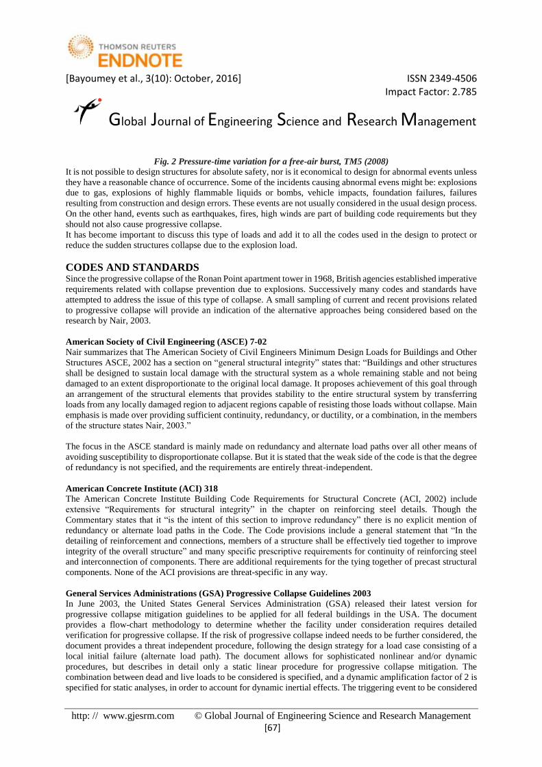
FREE AIR BLAST PHENOMENON A shock wave resulting from an explosive detonation in free air is termed an air-blast shock wave, or simply a
blast wave where no amplification of the initial shock wave occurs between the explosive source and the protective
structure. In the case of an airburst the pressure wave moves away from the center of the explosion and the blast
wave that hits the ground surface will be reflected Figure (2). The reflected wave will coalesce with the incident
wave and a Mach front is created, as shown in Figure (1) the point where the three shock fronts will meet, the
incident wave, reflected wave and the Mach front is termed the triple point, (TM5, 2008).
It will be clear from figures (2 and 3) that there are main parameters to be considered for design structures or
assessment existing structures, some of these parameters are:
1. Structure height.
2. Ground distance between bomb and structures.
3. Blast air pressure which based on the bomb weigh.
Fig. 1 Blast environment from an airburst, TM5 (2008)
[Bayoumey et al., 3(10): October, 2016] ISSN 2349-4506 Impact Factor: 2.785
Global Journal of Engineering Science and Research Management
http: // www.gjesrm.com © Global Journal of Engineering Science and Research Management
[67]
Fig. 2 Pressure-time variation for a free-air burst, TM5 (2008)
It is not possible to design structures for absolute safety, nor is it economical to design for abnormal events unless
they have a reasonable chance of occurrence. Some of the incidents causing abnormal evens might be: explosions
due to gas, explosions of highly flammable liquids or bombs, vehicle impacts, foundation failures, failures
resulting from construction and design errors. These events are not usually considered in the usual design process.
On the other hand, events such as earthquakes, fires, high winds are part of building code requirements but they
should not also cause progressive collapse.
It has become important to discuss this type of loads and add it to all the codes used in the design to protect or
reduce the sudden structures collapse due to the explosion load.
CODES AND STANDARDS Since the progressive collapse of the Ronan Point apartment tower in 1968, British agencies established imperative
requirements related with collapse prevention due to explosions. Successively many codes and standards have
attempted to address the issue of this type of collapse. A small sampling of current and recent provisions related
to progressive collapse will provide an indication of the alternative approaches being considered based on the
research by Nair, 2003.
American Society of Civil Engineering (ASCE) 7-02
Nair summarizes that The American Society of Civil Engineers Minimum Design Loads for Buildings and Other
Structures ASCE, 2002 has a section on “general structural integrity” states that: “Buildings and other structures
shall be designed to sustain local damage with the structural system as a whole remaining stable and not being
damaged to an extent disproportionate to the original local damage. It proposes achievement of this goal through
an arrangement of the structural elements that provides stability to the entire structural system by transferring
loads from any locally damaged region to adjacent regions capable of resisting those loads without collapse. Main
emphasis is made over providing sufficient continuity, redundancy, or ductility, or a combination, in the members
of the structure states Nair, 2003.”
The focus in the ASCE standard is mainly made on redundancy and alternate load paths over all other means of
avoiding susceptibility to disproportionate collapse. But it is stated that the weak side of the code is that the degree
of redundancy is not specified, and the requirements are entirely threat-independent.
American Concrete Institute (ACI) 318
The American Concrete Institute Building Code Requirements for Structural Concrete (ACI, 2002) include
extensive “Requirements for structural integrity” in the chapter on reinforcing steel details. Though the
Commentary states that it “is the intent of this section to improve redundancy” there is no explicit mention of
redundancy or alternate load paths in the Code. The Code provisions include a general statement that “In the
detailing of reinforcement and connections, members of a structure shall be effectively tied together to improve
integrity of the overall structure” and many specific prescriptive requirements for continuity of reinforcing steel
and interconnection of components. There are additional requirements for the tying together of precast structural
components. None of the ACI provisions are threat-specific in any way.
General Services Administrations (GSA) Progressive Collapse Guidelines 2003
In June 2003, the United States General Services Administration (GSA) released their latest version for
progressive collapse mitigation guidelines to be applied for all federal buildings in the USA. The document
provides a flow-chart methodology to determine whether the facility under consideration requires detailed
verification for progressive collapse. If the risk of progressive collapse indeed needs to be further considered, the
document provides a threat independent procedure, following the design strategy for a load case consisting of a
local initial failure (alternate load path). The document allows for sophisticated nonlinear and/or dynamic
procedures, but describes in detail only a static linear procedure for progressive collapse mitigation. The
combination between dead and live loads to be considered is specified, and a dynamic amplification factor of 2 is
specified for static analyses, in order to account for dynamic inertial effects. The triggering event to be considered

[Bayoumey et al., 3(10): October, 2016] ISSN 2349-4506 Impact Factor: 2.785
Global Journal of Engineering Science and Research Management
http: // www.gjesrm.com © Global Journal of Engineering Science and Research Management
[68]
is the failure of one ground floor column. The static linear procedure actually consists in a sequence of static linear
computations, eventually yielding an estimate of the extent of damage in the structure. This extent is then mirrored
with the region in which the guidelines consider damage to be tolerated, in order to validate the design, or point
to further reinforcements of the structure. Irrespectively of the validity of the underlying assumption for the GSA
static linear procedure, these guidelines are among the most complete, in that they instruct the practitioner in all
steps of the design process. Only the DoD (Department of Defense) guidelines, provide such details in the
procedures to be applied.
Department of Defense (DoD) guidelines
In June 2005, the United States Department of Defense issued its latest guidelines for progressive collapse
prevention. Buildings are categorized depending on the required level of protection. When a very low or low level
of protection is required, the safety of the structure is ensured through horizontal and vertical ties, while an
alternate path approach is prescribed, in addition to the ties for higher protection levels. A step-by-step procedure
is provided for a linear static analysis, for a non-linear static analysis, and for a non-linear dynamic analysis. The
load combination, involving dead, live and wind loads, is specified, along with a dynamic amplification factor of
2 for static analyses. The DoD step-by step procedure for linear static analysis is similar to the GSA procedure in
its general philosophy. The main differences lie in the choices for material behavior used in the simulations, and
in the fact that the static and dynamic non-linear procedures are detailed in the DoD guidelines.
British standards
British standards rely on tying force provisions to ensure safety against progressive collapse. If these requirements
cannot be met, an alternate load path analysis is specified. This standard suffer from two deficiencies. The first
one is that they do not take the sections and connections ductility into account, and it has been shown elsewhere
that these provisions may lead to unrealistic ductility demands for the beams sections and connections.
Furthermore, in the cases where an alternate load path analysis is to be performed, neither standards specify any
computational procedures. Only the loads and final requirement are specified. Any well validated alternate load
path procedure thus appears as an added value to the British standards.
Eurocodes
The Eurocodes also adopt the three approaches discussed so far. A classification of buildings into four classes is
provided, based on the consequences if collapse were to occur. For the lowest class, no progressive collapse
requirements are to be met. For the second class, only horizontal tie force requirements are specified. For the two
remaining classes, not only should tie requirements be met, but the structure also needs to be designed for the loss
of a vertical load bearing element, with damage not exceeding a specified region. If the damage is too extensive,
the vertical load bearing element is considered as a key element, and should be designed to withstand an additional
pressure of 34 kN/m². Again, no computational procedure is specified for the alternate load path analysis.
U.S. National Institute of Standards and Technology (NIST)
The document released by NIST in February 2007, entitled “Best Practices for Reducing the Potential for
Progressive Collapse in Buildings”, does not purport to provide detailed numerical procedures for progressive
collapse simulation. Instead, it offers an overview of the approaches for progressive collapse mitigation, some
general guidelines for structural integrity, and a review of available standards for design against progressive
collapse, such as the GSA or DoD documents.
International Atomic Energy Agency (IAEA) Safety Standards NS-G-1.7
IAEA goes directly to give a general consideration and recommendation against internal or external explosions
and mentioned that Structures, systems and components important to safety are required to be designed and
located, consistent with other safety requirements, so as to minimize the likelihood and effects of internal fires
and explosions caused by external or internal events. The capability for shutdown, removal of residual heat,
confinement of radioactive material and monitoring of the state of the plant is required to be maintained. These
requirements should be met by the suitable incorporation of redundant parts, diverse systems, physical separation
and design for fail-safe operation such that the following objectives are achieved
For protection against explosions, the following steps should be taken, in order of priority:
(a) Prevent explosions from occurring;

[Bayoumey et al., 3(10): October, 2016] ISSN 2349-4506 Impact Factor: 2.785
Global Journal of Engineering Science and Research Management
http: // www.gjesrm.com © Global Journal of Engineering Science and Research Management
[69]
(b) Minimize the risk of an explosion, if an explosive atmosphere cannot be avoided;
(c) Implement design provisions necessary to limit the consequences of an explosion.
Item (c) should only be necessary in exceptional cases, in which items (a) and, (b) cannot be achieved.
National Fire Protection Association (NFPA)
In the meeting of “Technical Committee on Explosives” on August 1-2, 2011, they did not specify any analysis
method or criteria, but added a new text for NFPA-495, chapter 11 as follow:
The International Society of Explosives Engineers (ISEE) Blast Vibration and Seismograph Section provides a
forum for the discussion of issues related to ground and air vibration from mine, quarry and construction blasting.
The Vibration Limits Technical committee was established to promote the use of uniform safe ground and air
vibration levels for blasting in mines, quarries and construction. The committee recognizes that reasonable and
scientifically based levels and practices are critical for successful blasting projects and protection of the nearby
public and property. It is the hope of this committee that this proposal will help improve the uniformity of
regulatory practices between jurisdictions and help prevent the promulgation of unrealistic regulations.
The ISEE, through the Blast Vibration and Seismograph Section has developed two documents that will form the
basis for the proposed change:
(a) "Performance Specifications for Blasting Seismographs" (2000)
(b) "Field Practice Guidelines for Blasting Seismographs" (1999)
The document "Performance Specifications for Blasting Seismographs" deals with the accuracy of blasting
seismographs from a mechanical and electronic perspective. The second document "Field Practice Guidelines for
Blasting Seismographs" recommends field deployment practices.
Egyptian Code of Practice for Design Reinforced Concrete Structures (ECP) It is absent in ECP any data or criteria showing how the designer can consider the explosions loads and blast air
pressure in the buildings design.
Unified Facilities Criteria (UFC 3-340-02) December 2008
Starting from this standards we will find a specific method to analyze any part of building like masonry walls,
reinforcing masonry walls, retaining structures, facades with or without opening and super structures against
explosions, and how we can construct suitable connections to prevent or at least reducing the progressive collapse
of the building. UFC 3-340-02 mentioned clearly that, blast loads on structures can be divided into two main
groups based on the confinement of the explosive charge (unconfined and confined explosions) and can be
subdivided based on the blast loading produced within the donor structure or acting on acceptor structures. These
blast loading categories are illustrated in Figure (3). Figure (3) gives the six blast loading categories possible.
Figure (1) also shows the five possible pressure loads associated with the blast load categories, the location of the
explosive charge which would produce these pressure loads, and the protective structures subjected to these loads.
The blast loading on a structure caused by a high-explosive detonation is dependent upon several factors:
(1) The magnitude of the explosion.
(2) The location of the explosion relative to the structure in question (unconfined or confined).
(3) The geometrical configuration of the structure.
(4) The structure orientation with respect to the explosion and the ground surface (above, flush with, or
below the ground).
The procedures presented here for the determination of the external blast loads on structures are restricted to
rectangular structures positioned above the ground surface where the structure will be subjected to a plane wave
shock front. The procedures can be extended to include structures of other shapes (cylindrical, arch, spherical,
etc.) as well as structures positioned at and below the ground surface.

[Bayoumey et al., 3(10): October, 2016] ISSN 2349-4506 Impact Factor: 2.785
Global Journal of Engineering Science and Research Management
http: // www.gjesrm.com © Global Journal of Engineering Science and Research Management
[70]
Fig.3 Blast Loading Categories
As mentioned in the abstract that the main aim of this paper how can implement a simplified method to calculate
the blast effect on the reinforced concrete structures or select a most standard close to the Egyptian Code. We can
observe from the above clause “Codes and Standards” that UFC 3-340-2 the only standard has a clear
recommendations and has an analysis method by using Time History Analysis during study the explosion effect.
MODEL DEVELOPMENT The structure selected for this study is an existing structure with bullet proof glass façade and it is consisting of5
stories reinforced concrete building standing at height of 24.425m. The center-to-center plan dimensions are
33.60m in both direction. The first story height is 4.00m, for typical floors the height is 3.85m and for the upper
roof story the height is 2.775m.
The floors layout and dimensions as shown in Figure (4).
The structural system of the building was made of reinforced concrete frames. The common beam size used is
300X600 mm; the columns size was varied from 300X550mm to 350X1100mm, and slabs thickness was varied
from 150 mm to 180 mm. This building included one core connected with shear wall and another single shear
wall with thickness 300 mm for each.
Fig. 4-a Columns and Axes Fig. 4-b Typical Floor Layout
1
A
2 3 4 5 6 7 8
B
C
D
E
F
G
H
5600200056007200560020005600
5600
2000
1100
4500
7200
5600
2000
5600
1000
23003000
300
7200
300
30002300
5600 2000 5600 7200 5600 2000 5600
5600
2000
5600
7200
5600
2000
5600
DN
UP
DN
DN
1 2 3 4 5 6 7 8
A
B
C
D
E
F
G
H

[Bayoumey et al., 3(10): October, 2016] ISSN 2349-4506 Impact Factor: 2.785
Global Journal of Engineering Science and Research Management
http: // www.gjesrm.com © Global Journal of Engineering Science and Research Management
[71]
Fig. 4-c Roof Floor Layout
Modeling of frame
The space frame building is modeled in ETABs 2013. The beams and columns are modeled as frame elements,
the slab is modeled as a shell element, and cores are modeled as reinforced concrete wall elements. The bottom
of frame is hinged. The diaphragm action is considered at every floor level. The beams and columns are properly
connected using the end offset provisions.
Figure (5) shows the 3D model of the frame building using ETABs.
Floors Elevation
Base Elevation = 0.000
Ground Elevation = 2.100 m
First Elevation = 6.250 m
Second Elevation = 10.100 m
Third Elevation = 13.950 m
Fourth Elevation = 17.800 m
Roof Elevation = 21.650 m
Upper Roof Elevation = 24.425 m
Fig. 5 3D Model for Frame Building by ETABs
5600 2000 5600 7200 5600 2000 5600
5600
2000
5600
7200
5600
2000
5600
1
A
2 3 4 5 6 7 8
B
C
D
E
F
G
H

[Bayoumey et al., 3(10): October, 2016] ISSN 2349-4506 Impact Factor: 2.785
Global Journal of Engineering Science and Research Management
http: // www.gjesrm.com © Global Journal of Engineering Science and Research Management
[72]
Computational Study The computational study which will be presented through this paper will cover three regulations GSA,
Eurocodes, and UFC 3-340-02 to get which one is more closed to realistic case.
Table 1. Blast load Simulation in GSA, Eurocodes, and UFC
Regulation Blast Simulation Blast Load
GSA
Static nonlinear
analysis and P-
Delta effect is
considered.
Increase the amplification factor to be 2 for dead and live load
combinations. Dead and live loads are applied on all structural
elements.
Eurocodes Static linear Uniform Pressure = 3.40t/m2 applied on a key structural
elements (in this study key structural element is the core).
UFC-3-340-02
Time – History
analysis, as per
specified in UFC.
As mentioned and specified in regulation and it will depend
in bomb weight, and ground distance. Blast loads will be
applied on external façade or exterior walls.
Blast load added in combination of dead load and live load.
The stories displacements in accordance with select regulations mentioned above will be illustrated through the
following charts:
1st regulation: General Services Administrations (GSA) Progressive Collapse Guidelines 2003
Fig. 6 Floors Displacement According to GSA
2nd regulation: Eurocodes Standard
Fig. 7 Floors Displacement According to Eurocodes
3rd regulation: Unified Facilities Criteria (UFC 3-340-02) December 2008

[Bayoumey et al., 3(10): October, 2016] ISSN 2349-4506 Impact Factor: 2.785
Global Journal of Engineering Science and Research Management
http: // www.gjesrm.com © Global Journal of Engineering Science and Research Management
[73]
In UFC regulation blasting calculations are depending on structure height, charge weight, and ground distance.
All these factors are taken in consideration and presented in Table-2.
Table 2. Maximum Pressure Applied on Bullet Proof Glass
Floors displacement time
The stories displacement time will show only for listed cases mentioned in (Table 3).
Table 3. Selected Blast Load Cases
Blast Load
Case
Bomb Weight
(Kg) TNT
Ground
Distance (m)
Max. Displacement
Time (ms)
1
500
10 3.44
2 20 11.82
3 30 17.96
4 40 18.46
5 50 25.06
6
3000
30 14.44
7 40 23.43
8 50 24.18
9
5000
30 16.19
10 40 21.19
11 50 31.22
Floors displacement charts
Fig.8 Case 1 (W= 500Kg, R= 10m) Fig.9 Case 2 (W= 500Kg. R= 20m)
500 3000 5000
10 595.852
20 56.667
30 16.24 105.461 171.268
40 10.187 44.293 76.898
50 6.721 24.941 42.184
W - Bomb Weight (Kg) TNT
R -
Gro
un
d D
ista
nce (
m)

[Bayoumey et al., 3(10): October, 2016] ISSN 2349-4506 Impact Factor: 2.785
Global Journal of Engineering Science and Research Management
http: // www.gjesrm.com © Global Journal of Engineering Science and Research Management
[74]
Fig.10 Case 3 (W= 500Kg, R= 30m) Fig.11 Case 4 (W= 500Kg, R= 40m)
Fig.12 Case 5 (W= 500Kg, R= 50m) Fig.13 Case 6 (W= 3000Kg, R= 30m)
Fig. 14 Case 7 (W= 3000Kg, R=40m) Fig. 15 Case 8 (W= 3000Kg, R= 50m)

[Bayoumey et al., 3(10): October, 2016] ISSN 2349-4506 Impact Factor: 2.785
Global Journal of Engineering Science and Research Management
http: // www.gjesrm.com © Global Journal of Engineering Science and Research Management
[75]
Fig.16 Case 9 (W=5000Kg, R= 30m) Fig.17 Case 10 (W=5000Kg, R= 40m)
Fig.18 Case 11 (W=5000Kg, R= 50m)
RESULTS AND DISCUSSION Based on what shown from displacement values through above charts, the following remarks are observed:
1- GSA Regulation
- Blast load is not specified just increase the amplification factor for dead and live combination which
means that the charge weight and ground distance are not taken in consideration.
- Blast loads direction cannot be determined because it is considered in a combination of vertical
loads.
- Maximum displacement is 1.13 cm and occurred at elevation 21.65 m, while maximum displacement
occurs normally at lower floors for this study.
2- Eurocode Standards
- Blast load is not specified as a uniform pressure equal to 3.40 t/m2 and applied on structural elements
bearing vertical loads or in key structural elements like cores and shear walls.
- If the uniform pressure applied on vertical structural elements it is necessity to distribute the pressure
as per stiffness and spacing between it, or choose the extreme and applied the pressure on cores or
shear walls. In case of applying on cores and shear walls it will apply in X and Y directions.
- Blast uniform pressure is implemented in vertical load combination.
- Maximum displacement is 2.80 cm and occurred at elevation 21.65 m, while maximum displacement
occurs normally at lower floors for this study.
3- UFC-3-340-02 Regulation
- In this regulation the analysis is based on blast wave which is subjected directly on external walls or
facade.
- As illustrated in above charts and table-1, analysis procedure based on time-history analysis which
allows to study the blast effect on each side of the building at any direction in same time.

[Bayoumey et al., 3(10): October, 2016] ISSN 2349-4506 Impact Factor: 2.785
Global Journal of Engineering Science and Research Management
http: // www.gjesrm.com © Global Journal of Engineering Science and Research Management
[76]
- Maximum displacement is achieved in lower floor of the building which is matching with blast free
air blast phenomena.
- Displacements value is varied based on the bomb weight and ground distance.
CONCLUSIONS Based on what mentioned above in results and discussion most realistic regulation is (UFC-3-340-02), which is
applicable to use for any type of buildings. The used equations to calculate the displacement are un-factored which
give a chance to merge it with Egyptian Code of Practice for Design Concrete Structure equations and can be
verified by Egyptian Code displacement limits.
ACKNOWLEDGMENT The author Ahmed A. Bayoumey thanks Prof. Dr. Walid A. Attia for the many valuable comments to the
manuscript.
COMPLIANCE WITH ETHICAL STANDARDS This study is theoretical study and it is personal effort from the authors and no funding, and this paper will be a part of PhD
thesis, which will be discussed in Cairo University – Faculty of Engineering.
Conflict of Interest: The authors declare that they have no conflict of interest.
REFERENCES 1. Fatih Tahmilci, “Analysis of Blast Loading Effect on Regular Steel Building Structures” in Middle East
Technical University, Master in Science Thesis, DECEMBER 2007.
2. M. Laissy and W. Attia, “Finite Element Analysis of Blast and Low-Velocity Impact on Sandwich Panels
with Multiple Suppressive Cores” in Cairo University, Faculty of Engineering, Doctor of Engineering
Thesis, 2010.
3. H.S.Lew, “Best Practices Guidelines for Mitigation of Building Progressive Collapse” in National
Institute of Standards and Technology, Gaithersburg, Maryland, U.S.A 20899-8611.
4. P. Bouillard, “Progressive collapse comparison of main standards formulation and validation of new
computational procedures”, in Dissertation originale présentée en vue de l’obtention du grade de Docteur
en Sciences de l’Ingénieur, 2008-2009.
5. International Atomic Energy Agency (IAEA) Standards Series, “PROTECTION AGAINST
INTERNAL FIRE AND EXPLOSIONS IN THE DESIGN OF NUCLEAR POWER PLANT”, Safety
Guide, NS-G-1.7.
6. National Fire Protection Association, “TECHNICAL COMMITTEE ON EXPLOSIVES – NFPA”,
AUGUST 1-2, 2011.
7. Unified Facilities Criteria (UFC), “STRUCTURES TO RESISIT THE EFFECTS OF ACCIDENTAL
EXPLOSIONS”, UFC 3-340-02, DECEMBER 2008.
8. American Concrete Institute 318 (ACI 318)
9. United States General Services Administration (GSA), 2003.
10. Department of Defense (DoD), 2005.
11. British Standards (BS 8110).
12. National Institute of Standards and Technology (NIST), 2007.
13. Egyptian Code of Practice for Reinforced Concrete Design, 2012.