Embed Size (px)
Citation preview
BLANCCO ERASURE SOFTWARE User manual for x86 erasure client version 4.9
30.3.2009
2 / 36
TABLE OF CONTENTS 1. GLOSSARY .......................................................................................................4
2. GENERAL INFORMATION.................................................................................5 Minimum System Requirements .......................................................................................................5
Booting and Computer Settings .......................................................................................................5
3. BLANCCO ERASURE SOFTWARE ......................................................................6 3.1. Function keys ..........................................................................................................................8
[F2] Change language / Keyboard layout..........................................................................................8
[F3] Select overwriting method / options ..........................................................................................8
[F4] HexViewer ..............................................................................................................................9
[F5] Reports, Load previous reports / Check report integrity...............................................................9
[F6] Option to run additional SMART tests ........................................................................................9
[F7] Bad disk option [Displayed only when the computer has SCSI hard disks] ....................................9
[F8] HASP Activation tool [Displayed only when HASP is enabled].....................................................10
[F9] License.................................................................................................................................10
3.2. Erasure Report ......................................................................................................................11
4. BES SECURITY FEATURES..............................................................................12 Detecting hard disk.......................................................................................................................12
Bad sector handling ......................................................................................................................12
Remapped sectors ........................................................................................................................13
Host Protected Area (HPA) ............................................................................................................14
Device Configuration Overlay (DCO)...............................................................................................14
Erasure verification.......................................................................................................................15
5. OPTIONAL FEATURES ....................................................................................16 5.1. Hardware tests......................................................................................................................16
Automatically operated tests..........................................................................................................16
Memory test.................................................................................................................................16
CPU.............................................................................................................................................16
Motherboard ................................................................................................................................17
Manually operated tests ................................................................................................................17
Pointing devices ...........................................................................................................................17

3 / 36
Display ........................................................................................................................................18
Keyboard .....................................................................................................................................19
Optical devices .............................................................................................................................20
Floppy drive .................................................................................................................................20
Sound .........................................................................................................................................20
5.2. Customized erasure reports..................................................................................................21
5.3. Fetching information from Windows Registry......................................................................21
5.4. Static Password protection...................................................................................................21
5.5. Using the software with a Serial Console .............................................................................22
6. TROUBLESHOOTING......................................................................................24 Changing the boot sequence and accessing BIOS............................................................................24
Burning the *.iso image / Creating the CD ......................................................................................25
Using a non-graphical user interface ..............................................................................................25
Debug utilities for troubleshooting .................................................................................................26
Boot loader error descriptions........................................................................................................27
Deficient BIOS clock .....................................................................................................................27
Unable to save report notification ..................................................................................................27
Skipping loading modules that cause the system to freeze ...............................................................27
Unable to access DCO feature set ..................................................................................................28
7. ERASURE OF STORAGE SYSTEMS ..................................................................29 What should be considered if erasing logical arrays?........................................................................29
Erasing RAID configurations with Blancco Server Edition. .................................................................30
Erasing hard drives not detected through RAID adapter...................................................................31
Requirements for storage system data erasure................................................................................31
Procedure for EMC CX400 SAN storage systems ..............................................................................32
Erasing the hardware that is not supported by Blancco ....................................................................33
8. CONTACT BLANCCO SERVICE ........................................................................34
9. LICENSE AGREEMENT....................................................................................35

4 / 36
1. GLOSSARY
ITEM EXPLANATION
ATA Short for Advanced Technology Attachment, a HDD standard.
BES Blancco Erasure Software
BIOS Acronym for Basic Input/Output System. On PCs, BIOS contains all the code required to control for example keyboard, display screen and disk drives.
DCO Device Configuration Overlay, which allows system vendors to purchase HDDs from different manufacturers with potentially different sizes, and then configure all HDDs to have the same number of sectors.
Enhanced Secure Erase A way of erasing SCSI hard disks using internal HDD commands. This has the benefit of overwriting remapped sectors too.
Fibre Channel A serial data transfer architecture. The most prominent Fibre Channel standard is Fibre Channel Arbitrated Loop (FC-AL).
HASP An USB attached dongle that is used by Blancco to provide licenses.
Hard Disk Drive A computer device, which stores digital data on rapidly rotating platters with magnetic surfaces. In this document hard disk drive is shortened to HDD.
Hexviewer A Hexviewer is a type of computer program that allows a user to access binary computer files. Blancco Hexviewer can see HDD binary content.
HPA The Host Protected Area (HPA) as defined is a reserved area on a HDD. It was designed to store information in such a way that it cannot be easily modified, changed, or accessed by the user, BIOS, or the OS.
Remapped/Reallocated Sectors Count of reallocated sectors. When the hard drive finds a read/write/verification error, it marks this sector as "reallocated" and transfers data to a special reserved area (spare area).
SATA SATA is an evolution of the Parallel ATA physical storage interface. Serial ATA is a serial link – a single cable with a minimum of four wires creates a point-to-point connection between devices.
SCSI Short for Small Computer System Interface, a parallel interface standard used by Apple Macintosh computers, PCs, and many UNIX systems for attaching peripheral devices to computers.
Secure Erase A way of erasing ATA or SATA hard disks using internal HDD commands. This has the benefit of overwriting remapped sectors too.
SMART Self-Monitoring, Analysis, and Reporting Technology or S.M.A.R.T. (in this manual written SMART), is a monitoring system for computer hard disks to detect and report on various indicators of reliability, in the hope of anticipating failures.
5 / 36
2. GENERAL INFORMATION This manual is written for the Blancco Erasure Software family for x86-based computer architectures, namely Blancco PC Edition, Blancco Server Edition and Blancco Data Centre Edition.
PLEASE READ CAREFULLY THE NEXT PARAGRAPH BEFORE YOU START USING THE PROGRAM!
Thank you for choosing Blancco for your data erasure needs. Before you start using the Blancco Client software make sure that all files, folders, software applications or any other information that you want to save for later use are backed up on an appropriate media device other than the original hard drive. If you are not sure whether to erase the information on the hard disk, please contact your system operator, information management or a corresponding party, which maintains the computers in your organization. For future use of the erased computer an operating system must be installed. Data that has been erased from the hard disk by this program cannot be recovered by any existing method. Please note that Device Configuration Overlay (DCO) settings and the Host Protected Area (HPA) will be reset to the default settings during the Blancco software boot.
Minimum System Requirements 1. x86 architecture machine (Intel/AMD based PC) with 486DX processor or better 2. 32 MB RAM memory in most cases, erasing servers with 12+ hard disks needs more RAM 3. CD-drive (Blancco Erasure Client 4.7 or older can be booted from floppy drive) 4. SVGA display for graphical user interface 5. [Optional] Network card for Management Console and www.blanccoservice.com solutions.
Booting and Computer Settings • Check that all the hard drives are attached properly to the computer. Every erasure uses one
license (when using PC-based licensing) so you want to erase all the hard drives in one run. • If you have a laptop computer plug in the power adapter. There may be problems when
erasing a laptop on battery power. • Disable or type the BIOS passwords requested during the booting up. This means the
passwords that some computers require even before the actual booting starts. Other kinds of BIOS passwords do not usually prevent erasing the hard disks.
• Disable power saving qualities from BIOS. Note! This step is usually not needed, but some hardware may have problems if power saving is enabled, so if you have just one license it is prudent to do this. In recycling centre or corporate environment this should be done only if there are problems with the given computer model when the power saving is on.
• If your Blancco software is in .iso image form, burn it to CD. • Switch-on the computer power, put in the Blancco CD and boot the system from the CD.
Read section “Changing the boot sequence and accessing BIOS” for further info. • Follow the user instructions in order to start erasing the data. Double-check that all hard
disks have been detected correctly, because this is needed to erase all the data from them.
Note! By default Blancco PC Edition can erase up to 4 hard disks, one at a time. Blancco Server Edition can erase up to 16 hard disks simultaneously and Blancco Data Centre Edition can erase up to 256 hard disks simultaneously.
Warning! Shutting the computer down when it is performing remapped sector erasure, NIST 800-88 secure erase (+assurance) or Extended NIST 800-88 can permanently damage the hard disks.

6 / 36
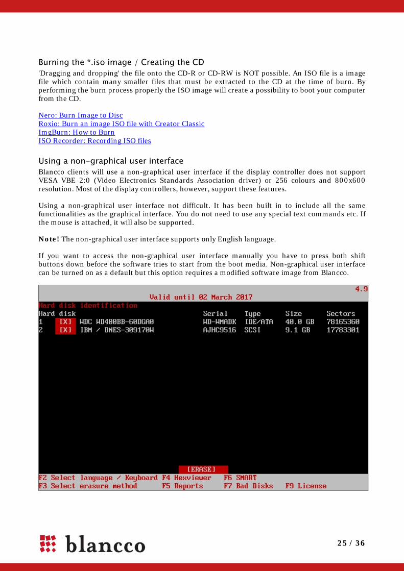
3. BLANCCO ERASURE SOFTWARE Note! In this manual BES and Blancco Erasure Software are used interchangeably. Step 1/3: Hard Disk Selection Page Hard drives in the computer are shown. Please check that the hard drives have been correctly identified. If a hard drive contains partitions, you are able to select and deselect them for overwriting with a keyboard or by clicking them with mouse. Selected partitions have red background in the user interface. Note that all hard disks are selected for erasure by default when the software starts. Start the erasure by clicking erase with the mouse or press tab-key until erase is selected and press enter. You will be asked to confirm the erasure before it starts.
If the name of the hard disk is red, what does it mean?
• If you are doing Secure Erase or Enhanced Secure Erase, a red font means that the hard disk does not support the internal HDD commands needed for the erasure.
• If you are erasing a hard disk and erasing remapped sectors, the red font means that remapped sector erasure is not supported.
Function keys [F2] Language and Keyboard settings [F3] Select erasure method, with optional features of remapped sector erasure, full erasure
verification and copying the report to the hard disk boot sector [F4] Hexviewer, which allows the user to see the data contents of hard disk sectors [F5] Reports screen where saving the report is possible [F6] SMART tests [F7] Optional Bad Disk detection in server environment with SCSI hard disks [F8] Optional HASP Activate tool [F9] Blancco Erasure Software EULA (End User License Agreement)

7 / 36
Step 2/3: Erasing the Hard Disks Click “Erase “ and the software will overwrite the selected hard disks. Progress bar and time left indicator show how long it takes before the process is finished. You can click ESC to exit the software before the process is completed, but then the hard disks are not fully erased and Blancco cannot guarantee that no data remains in them. Also, you will not be able to see the erasure report if you exit the software before the erasure has finished. Step 3/3: Report Page Report screen, with buttons save and quit. After clicking save you are asked to select the detected device (floppy/USB port) on which you want to save the report. If you click quit you have to confirm the selection; After saving the report or after pressing “yes” to confirm, the “please shutdown the computer” screen will appear.
Note! Save and store the original erasure report. It is a document that proves that the erasure has been carried out according to the selected methods.
8 / 36
3.1. Function keys
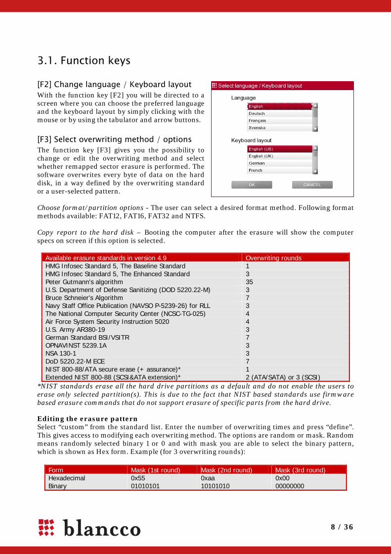
[F2] Change language / Keyboard layout With the function key [F2] you will be directed to a screen where you can choose the preferred language and the keyboard layout by simply clicking with the mouse or by using the tabulator and arrow buttons.
[F3] Select overwriting method / options The function key [F3] gives you the possibility to change or edit the overwriting method and select whether remapped sector erasure is performed. The software overwrites every byte of data on the hard disk, in a way defined by the overwriting standard or a user-selected pattern. Choose format/partition options - The user can select a desired format method. Following format methods available: FAT12, FAT16, FAT32 and NTFS. Copy report to the hard disk – Booting the computer after the erasure will show the computer specs on screen if this option is selected.
Available erasure standards in version 4.9 Overwriting rounds HMG Infosec Standard 5, The Baseline Standard 1 HMG Infosec Standard 5, The Enhanced Standard 3 Peter Gutmann's algorithm 35 U.S. Department of Defense Sanitizing (DOD 5220.22-M) 3 Bruce Schneier's Algorithm 7 Navy Staff Office Publication (NAVSO P-5239-26) for RLL 3 The National Computer Security Center (NCSC-TG-025) 4 Air Force System Security Instruction 5020 4 U.S. Army AR380-19 3 German Standard BSI/VSITR 7 OPNAVINST 5239.1A 3 NSA 130-1 3 DoD 5220.22-M ECE 7 NIST 800-88/ATA secure erase (+ assurance)* 1 Extended NIST 800-88 (SCSI&ATA extension)* 2 (ATA/SATA) or 3 (SCSI)
*NIST standards erase all the hard drive partitions as a default and do not enable the users to erase only selected partition(s). This is due to the fact that NIST based standards use firmware based erasure commands that do not support erasure of specific parts from the hard drive.
Editing the erasure pattern Select “custom” from the standard list. Enter the number of overwriting times and press “define”. This gives access to modifying each overwriting method. The options are random or mask. Random means randomly selected binary 1 or 0 and with mask you are able to select the binary pattern, which is shown as Hex form. Example (for 3 overwriting rounds):
Form Mask (1st round) Mask (2nd round) Mask (3rd round) Hexadecimal 0x55 0xaa 0x00 Binary 01010101 10101010 00000000

9 / 36
[F4] HexViewer HexViewer is a tool for checking the content of each sector on the hard drive. Quick buttons allow easy navigation to “first”, “prev”, “next”, “last” sector, or the user can just type the desired sector number to the box on the upper corner.
[F5] Reports, Load previous reports / Check report integrity By opening the “F5 Reports” page, the user will see a preview of the erasure report before executing the erasure and has the following options:
• User is able to fill in undetected fields • F9 Loads previous reports for a closer look without the ability to modify them. In addition,
if the reports have been modified with another tool, they will no longer be shown in Blancco Clients. This is a precautionary step by Blancco in order to verify that the report is authentic and has been generated by Blancco software. However, if a third party has modified it Blancco cannot take any responsibility for the report content.
• F10 Save the report to a floppy/USB drive. • F11 Send the report to Blancco Management Console • F12 Closes the screen
[F6] Option to run additional SMART tests The Blancco client can do two variations of SMART tests: short and long. Both take some time and report hard disk health status. Usually the result of the test is success or failure, with some rarer error messages possible.
[F7] Bad disk option [Displayed only when the computer has SCSI hard disks] Broken SCSI hard disks are not shown on the Blancco Server Edition / Blancco Data Centre Edition hard disk selection page, as erasing these is not possible. Key [F7] starts a tool that searches for bad disks and if failing disks are present in the system, Server Edition / Data Centre Edition will show them in a popup that lets the user to flash the lights of broken disks in the rack and to repair them.
Warning! Do not turn off the computer or cancel the repair process or the SCSI disk can be damaged. If power shortage will appear try to re-run the tool again in order to get the disks back in to a functional state.
10 / 36
[F8] HASP Activation tool [Displayed only when HASP is enabled] Connect the USB stick that contains the license code and click [F8] to open HASP activation dialog. Select the license code file from the USB and click it to add erasure licenses to the HASP dongle.
The activation key request should contain the ID of the HASP key and the types of the client software and the number of licenses for each type. The activation key file will be sent by email or other agreed upon means and your account will be charged with the licenses offered in the activation key. These are the steps to update the HASP licenses:
1. Save the activation key received from sales representative or blanccoservice.com to USB
2. Plug the HASP dongle and the USB drive with the activation key file into the computer where Blancco is running
3. Click on ACTIVATE on the dialog that notifies about license insufficiency. If you want to ADD licenses just press F8 in order to get “Load activation key” pop up.
4. On the “Load activation key” choose the drive where the activation file is located
5. Select the displayed *.hsp file
6. Click on the LOAD button and licenses are activated
7. Start using Blancco licenses. License of the used product is taken immediately after you have started the erasure.
Note! Make sure the HASP key is connected and if the activation is successfully done, the license information displayed at the top centre of the screen will be updated and if enough licenses were acquired, further operations will be allowed. The activation key can be used only one time.
[F9] License Click [F9] to read Blancco Client license agreement.
11 / 36
3.2. Erasure Report At the end of the erasure the report is shown. The status of each erased disk (erasure completed successfully, with errors, with exceptions or with errors and exceptions) is written, colour coded so that the result is easy to see. Green text means that the erasure was successful.
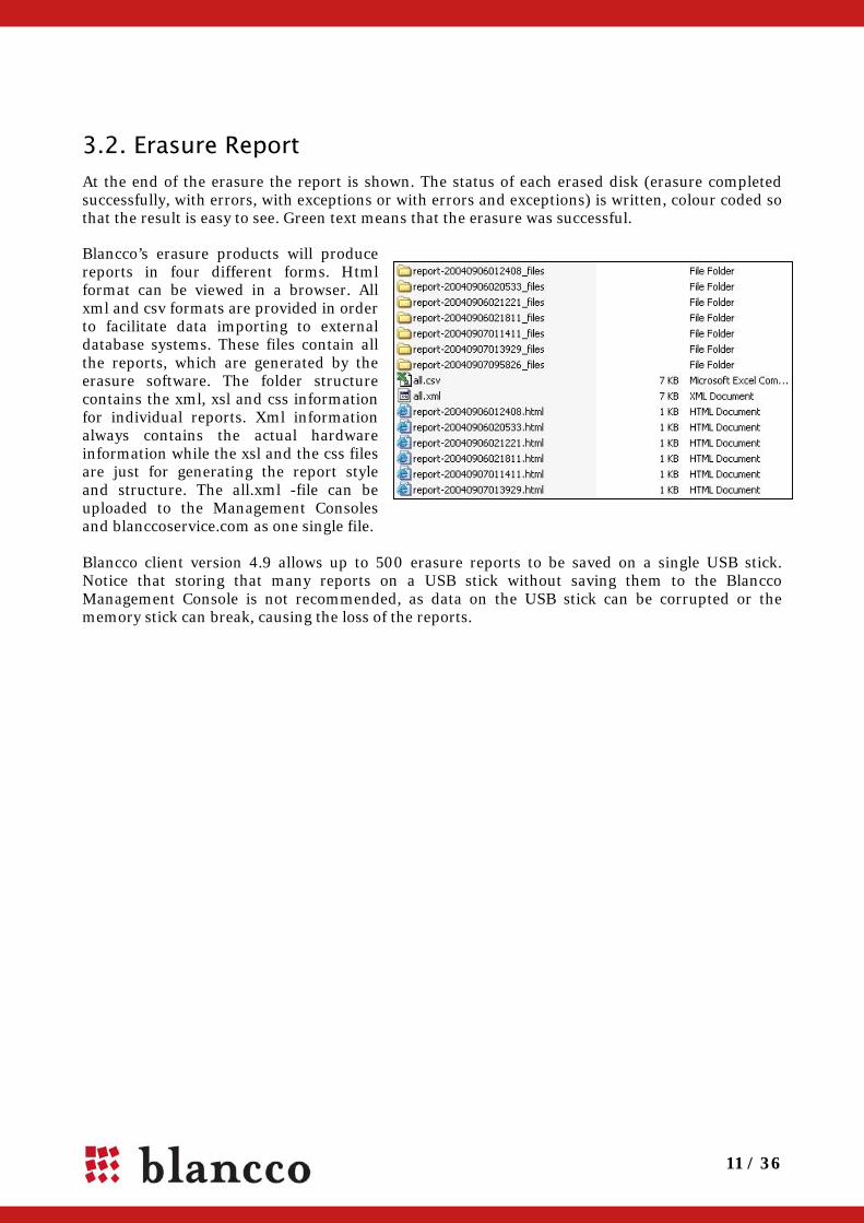
Blancco’s erasure products will produce reports in four different forms. Html format can be viewed in a browser. All xml and csv formats are provided in order to facilitate data importing to external database systems. These files contain all the reports, which are generated by the erasure software. The folder structure contains the xml, xsl and css information for individual reports. Xml information always contains the actual hardware information while the xsl and the css files are just for generating the report style and structure. The all.xml -file can be uploaded to the Management Consoles and blanccoservice.com as one single file. Blancco client version 4.9 allows up to 500 erasure reports to be saved on a single USB stick. Notice that storing that many reports on a USB stick without saving them to the Blancco Management Console is not recommended, as data on the USB stick can be corrupted or the memory stick can break, causing the loss of the reports.

12 / 36
4. BES SECURITY FEATURES
Detecting hard disk Magnetic storage medias like hard disks use physical addressing when storing information on a media. With this addressing the hard disk is divided into smaller parts that can be appointed according to certain parameters. In magnetic media the mentioned physical parameters are sectors, cylinders and heads. During the computer usage these parameters enable the operating systems to locate the information on a hard disk but they also define the size and storage base of a hard disk. A reliable and protected detection of these hardware level parameters is essential and the erasure software must be capable of detecting the correct hard disk sizes regardless of the techniques used in altering the hard disk information. Failure in accurately detecting the hard disk may result in an incomplete erasure of the hard disk. All Blancco data erasure tools utilize hardware level detection for hard disks enabling the software to detect correct hard disk sizes regardless of faulty or incorrect BIOS set hard disk values. As a result, the overwriting process will reach the whole hard disk surface leaving no areas untouched.
Bad sector handling Even though the incorrectly configured, faulty or damaged configurations cause a potentially remarkable data security risk there are also other gaps that need to be addressed in order to guarantee a secure data erasure process. Hard disks might contain damaged areas that cannot be accessed with read nor write commands anymore, which makes those areas unusable. In data erasure terms these areas are called physical bad sectors and data erasure tools must be able to detect and especially report them. Blancco erasure client keeps track of the data erasure procedure and informs if the data erasure (overwrite) cannot be performed due to some error on the hard disk. E.g. in case there are any bad sector(s) found on the hard disk, the software will try to write a data block to the defective area. If the area remains “silent” Blancco will try to write a smaller block (half of the original block size) to the defective area in order to overwrite the maximum amount of data. The same procedure will continue until the software tries to write the smallest possible block to the hard drive and if unable to do so the sector will be marked as physical bad sector. This procedure offers extremely accurate erasure even in cases of bad sectors so that all the possible areas will be erased and only the real bad sectors/areas will be reported. The bad sectors will be reported in the user interface and also in the erasure certificate that is produced after each erasure.

13 / 36
Remapped sectors Modern hard drives have a lot of functions for self-testing, self-recovering and keeping track of their state. One of the possibilities is sector remapping. This allows the hard drives to detect and hide the sectors, which will either be or have become impossible to access. The hard drives have a so-called spare area intended precisely for this. When a failed sector is detected, the hard drive controller assigns the address of the sector to a new one in the spare area. So the address remains the same but the owner is changed. The remapped sector may contain some of the user's data. With Blancco Clients the remapped sectors can be erased. Disable the BIOS hard disk detection when using Remapped Sector erasure. In many computers the remapped sectors can be erased even without changing BIOS settings, but by disabling the BIOS hard disk detection some problems can be avoided. Remapped sector erasure can be selected with any overwriting standard Blancco Erasure Client supports and it is enabled by default with the following erasure standards:
• HMG Infosec Standard 5, The Baseline Standard • HMG Infosec Standard 5, The Enhanced Standard • DoD 5220.22-M • DoD 5220.22-M ECE • Extended NIST 800-88 (SCSI&ATA extension)
In Extended NIST 800-88 (SCSI&ATA extension) standard the remapped sector erasure is forced on, so the user cannot switch it off.
If the remapped sectors are detected during the erasure processes the following text appears to the progress bar: “ESE Running”. Note that if “Extended NIST 800-88” erasure method is selected the Remapped Sector Destruction is performed to every hard disk. Erasing remapped sectors can be a time consuming process depending on the hard disk size and disk speed. Note! When erasing ATA hard drives with NIST 800-88/ATA secure erase (+ assurance), Extended NIST 800-88 (SCSI&ATA extension) or when erasing ATA hard disk remapped sectors, Blancco Erasure Software can erase one hard disk at a time per ATA channel. Warning! When 800-88/ATA secure erase (+ assurance), Extended NIST 800-88 (SCSI&ATA extension) or remapped sector erasure is selected, and a hard drive supports the method, Blancco Erasure Software does not show the partitions on the disk. The whole hard drive will be erased. If you want to erase just a partition, do not select one of these methods. Warning! Do not turn off the computer or cancel the erasure during the Remapped Sector Destruction process or the disks can be damaged.

14 / 36
Host Protected Area (HPA) Blancco software can detect the Host Protected Area and erase it. The HPA is commonly used to store the recovery part of the operating system and can contain sensitive data. When a Host Protected Area is found the area is erased as a default. Pop-ups are shown only if problems are occurring or the erasure software has been modified to allow the user to select if he wants to erase the HPA area or not. Note! In order to guarantee the functionality of this option, please disable the BIOS hard disk drive detection for proper detection and execution of Blancco. In some cases the computer must be rebooted in order to remove the HPA.
Device Configuration Overlay (DCO) Device Configuration Overlays (DCO) is another but less known optional feature set. It first appeared in the ATA-6 standard and because of this it does not have as many features as HPA. DCO enables the possibility to create special partition to hard disk where the user or operating system cannot access. This specified part of the hard disk creates a risk that some data might be left on the hard disk after the erasure unless the erasure product is capable of detecting and also extending and erasing DCO areas. Blancco erasure client products are able to detect, extend and erase DCO areas. In addition Blancco software reports the procedure to the user in the user interface and also in the erasure certificate. Q: Why doesn't Blancco over write this area? A: There is a BIOS low-level protection mechanism that locks DCO functionality and prevents disk configuration changes by some malicious software. If the protection mechanism cannot be disabled the message "Unable to reset DCO" is shown. The protocol is there, but the software cannot access it because the BIOS is blocking the access. Q: Is there a way around the DCO. A: If there is a DCO configured extra partition on the disk and BIOS freezes DCO functions then normally the freezing lock can be switched off from the BIOS settings e.g. turning off the hard disk detection. It is also possible to connect the disk to another machine with the required functionality to remove DCO. If there is no way to disable the DCO freezing lock it may be that there is a BIOS protecting mechanism against setting or removing the DCO partition. This usually means that there is no extra partition and the message “Unable to access DCO feature set. Remove auto detection of hard drives in BIOS to reset DCO.” will appear. Note! The final way to confirm that there are no extra partitions is to check from the manual or disk case the number of sectors and make sure that it corresponds to the one detected by Blancco erasure software.
15 / 36
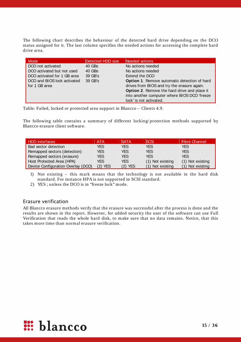
The following chart describes the behaviour of the detected hard drive depending on the DCO status assigned for it. The last column specifies the needed actions for accessing the complete hard drive area.
Mode Detected HDD size Needed actions DCO not activated 40 GBs No actions needed DCO activated but not used 40 GBs No actions needed DCO activated for 1 GB area 39 GB’s Extend the DCO DCO and BIOS lock activated for 1 GB area
39 GB’s Option 1. Remove automatic detection of hard drives from BIOS and try the erasure again. Option 2. Remove the hard drive and place it into another computer where BIOS DCO ‘freeze lock’ is not activated.
Table: Failed, locked or protected area support in Blancco – Clients 4.9.
The following table contains a summary of different locking/protection methods supported by Blancco erasure client software.
HDD interfaces ATA SATA SCSI Fibre Channel Bad sector detection YES YES YES YES Remapped sectors (detection) YES YES YES YES Remapped sectors (erasure) YES YES YES YES Host Protected Area (HPA) YES YES (1) Not existing (1) Not existing Device Configuration Overlay (DCO) (2) YES (2) YES (1) Not existing (1) Not existing
1) Not existing – this mark means that the technology is not available in the hard disk standard. For instance HPA is not supported in SCSI standard.
2) YES ; unless the DCO is in “freeze lock” mode.
Erasure verification All Blancco erasure methods verify that the erasure was successful after the process is done and the results are shown in the report. However, for added security the user of the software can use Full Verification that reads the whole hard disk, to make sure that no data remains. Notice, that this takes more time than normal erasure verification.
16 / 36
5. OPTIONAL FEATURES There are optional features in Blancco Client products, which are not included by default. Please check from your sales representative what features are included if you are not sure.
5.1. Hardware tests Blancco erasure clients can contain an inbuilt hardware test application. The application can perform up to 9 different test features for the hardware. The purpose of these hardware tests is to ensure the functionality of different computer components. By performing the tests the user is able to check and report the current condition of a computer. Assuring the functionality of a computer helps the user to sell/donate high quality second hand computers and enables the buyer to verify the condition of the purchased computer. Hardware tests include both fully automated and manually operated tests. Manually operated tests are based on visual and audio output that the system provides. Manually operated tests will have a pop-up with test related questions and buttons (Yes/No/Other button). Navigation in the software is handled with the mouse or keyboard shortcuts (Y -key/ N -key/ Other -key). Note! This option requires a modified software image from Blancco. Other than automatically operated tests could be performed before or after the erasure.
Automatically operated tests The following hardware tests are executed automatically before the Blancco software has been completely loaded to the computer. The user will see a progress bar on the screen for each test component. The testing process can take a while. If there is no time for performing the tests they can be skipped by pressing <Esc>.
Memory test The memory test checks the low and the extended memory of a computer automatically. The test time depends on the size of the memory and the speed of the processor. The results of the test can be either operational or failed. The tests are operated with certain data patterns. Each data pattern is first written to the memory and then read and verified.
CPU The CPU test checks the functionality of the processor. The CPU test is performed automatically and the test results are either operational or failed. CPU test checks the following features:
• ALU (Arithmetic Logic Unit) that performs arithmetic and logical operations • MMX (Multimedia Extensions) that handles multimedia operations
If the test fails the user is given an option to repeat the test or continue to the next phase.

17 / 36
to red.
Motherboard The motherboard test checks the functionality of CMOS (complementary metal oxide semiconductor) and other parts of the motherboard. The test gives operational/failed status for different parts of the motherboard. It tests the following motherboard features:
• CMOS battery: provides power to memory that contains date, time and system setup parameters
• CMOS checksum: warns if CMOS is corrupted • CMOS read/write • Keyboard controller circuit • Keyboard interface
Manually operated tests Manually operated tests require user interaction. After accepting the license agreement there are several options:
• [CONTINUE] skips the tests that require user interaction and goes directly to the hard drive erasure.
• [START ALL] performs pointer, display, keyboard, optical device, floppy and sound tests. • [START] performs one test e.g. the keyboard test.
Pointing devices The pointing device test checks the functionality of the mouse, touchpad or trackball. Different components of the pointing device are then shown on the screen. When a component passes the test the colour of the corresponding rectangle changes colour on the screen. The pointer position is shown in x- and y-coordinates. The following manual actions are required from the user:
• Left click on the pointing device => changes middle-left rectangle colour
• Right click on the pointing device => changes middle-right rectangle colour to red.
• The user must move the pointer to the other rectangles on the screen and make a left or right click on each rectangle.
After clicking on each rectangle the colour of the target rectangle changes to red. Actions listed above can be performed in any order. Clicking a rectangle or button, which is already red will not change the colour back to grey. When all the rectangles are red the test is over. End the pointing device test by pressing the [F3] key or by clicking the “F3 End test” text in the bottom left corner of the screen. The pop-up screen will appear and the user must confirm the test result. The following options are available:
• [Yes] – This will set the test result to “successful” • [No] – This will set the test result to “failed” • [Cancel] – This will set the test result to “not performed”

18 / 36
Display The display test is used to check the functionality of a display. The software displays several test screens for the user. First the user should see 5 different screens with different colours. After that the software displays a test pattern. Some of the test pattern lines are two coloured. If a two coloured line is shown as one continuous line the display is functioning correctly. The picture on the left is one of the colour test screens. The middle picture is the confirmation screen where you have to confirm if you where you able to see the blue colour. The picture on the right side is the test pattern picture.
Please answer “Yes” or “No” to the questions. If the test screen is not shown correctly there is an option to re-run the test screen, abort the hardware test altogether or proceed to next screen. The display test includes the following steps:
• White screen and text at the bottom of the screen “Press <SPACE> to continue” • Blue screen and text at the bottom of the screen “Press <SPACE> to continue” • Green screen and text at the bottom of the screen “Press <SPACE> to continue” • Red screen and text at the bottom of the screen “Press <SPACE> to continue” • Black screen and text at the bottom of the screen “Press <SPACE> to continue” • Test pattern and text at the bottom of the screen “Press <SPACE> to continue”
When each step is performed, the user is asked to validate the colour or test pattern. Please answer simply with a “Yes” or “No” to the validation questions. The display test can be aborted by choosing “Cancel”. Cancelling the display test sets the test result to “not performed”.

19 / 36
Keyboard The keyboard test is used to test the functionality of the keyboard. The keyboard test is performed manually. Before the actual test the user is able to choose the desired keyboard layout (see the picture below).
The keyboard layout is shown in small rectangles on the screen. When pressing a key, a corresponding rectangle turns to red on the screen. Releasing the key will not turn the colour back to grey. The response time for key press detection is short. Short response time allows the user to press the keys very fast e.g. dragging the finger over the keyboard or pressing several keys simultaneously. Please note that most of the keyboards can send only 3 key signals at once. You can also test the keyboard’s indicators (the LED lights) by pressing [CTRL] + [F4] keys. The indicators should be blinking for a while. End the keyboard test by pressing [CTRL] + [F3] keys or by clicking the “CTRL + F3 End test” text in the bottom left corner of the screen. The pop-up screen will appear and the user must confirm the test result. The following options are available:
• [Yes] – This will set the test result to “successful” • [No] – This will set the test result to “failed” • [Cancel] – This will set the test result to “not performed”

20 / 36
Optical devices The optical device test is used to test the functionality of the optical CD and DVD drives. After the system detects all the optical devices connected to the computer, user can insert a blank CD-RW/CD-R or DVD-RW/DVD-R disk or disk which contains the Blancco pattern. In the first case the software will perform both writing and reading tests of the optical drive, and in the second - the reading test only. User can download CD or DVD images from the from the following location:
http://download.blancco.com/Test_media/Test_CD_for_HW_Test.zip http://download.blancco.com/Test_media/Test_DVD_for_HW_Test.zip
Floppy drive The floppy drive test is used to test the functionality of the floppy drive. The floppy test tries to read the floppy from random locations. The floppy test does not need any special test floppy. If the floppy test is a success the system proceeds automatically to the next phase. If the test fails the user has the option to repeat the test or continue to the next phase.
Sound The sound test is used to test the functionality of the PC speaker. The system produces a beep sound and asks the user if the sound was heard or not. The following options are available:
• [Yes] – This will set the test result to “successful” • [No] – This will set the test result to “failed” • [Cancel] – This will set the test result to “not performed”

21 / 36
5.2. Customized erasure reports Blancco PC Edition and Server Edition generate detailed reports after each erasure process. The basic sheet contains fields for extra information, which can be filled in before saving the report. These fields are located at the end of the report and the fields are named as info1, info2, info3 etc. Blancco offers the possibility to create more customer specified erasure reports by adding extra fields with required titles to any part of the erasure report (e.g. extra1 = Internal AssetID, extra2 = CustomerID).
5.3. Fetching information from Windows Registry In the 4.9 versions of Blancco PC Edition and Server Edition the operation system version and serial number can be displayed. Also the list of installed software is shown. In the software list the name of software is always shown. Version and serial are shown if the software’s manufacturer provides them (see the picture below). Note! When hardware/software encryption is used or RAID Array has been dismantled in the hard disk drive Blancco is not capable of performing registry information gathering.
5.4. Static Password protection Blancco client software can be protected with a static password. In order to get this function discuss with your local sales representative.

22 / 36
5.5. Using the software with a Serial Console A special version of Blancco Erasure Client 4.9 that can be used with a Serial Console can be made.
Configuring Putty
PuTTY is an open source xterm terminal emulator that provides support for remote controlled printing. It is a multi-platform program that runs on both Windows and Linux. It is available from:
http://www.chiark.greenend.org.uk/~sgtatham/putty/download.html
Terminal settings
Select ‘Connection type:’ ‘Serial’ and type in the name of the serial port you are using to ‘Serial line’ field. Select ‘Keyboard’ from the ‘Terminal’ category. From ‘The Backspace key’ select ‘Control-H’ and from ‘The Function keys and keypad’ select ‘Xterm R6’.
You can save all the settings in the ‘Session’ category. Type in the name you wish to give for the session in the ‘Saved Sessions’ field and press ‘Save’.
23 / 36
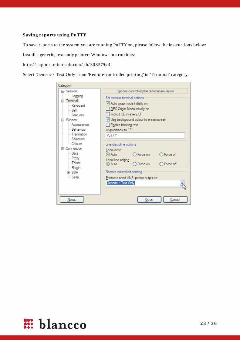
Saving reports using PuTTY
To save reports to the system you are running PuTTY on, please follow the instructions below:
Install a generic, text-only printer. Windows instructions:
http://support.microsoft.com/kb/308579#4
Select ‘Generic / Text Only’ from ‘Remote-controlled printing’ in ‘Terminal’ category.

24 / 36
6. TROUBLESHOOTING
Changing the boot sequence and accessing BIOS In order to boot Blancco software set the used device (USB/CD) as a first booting device.
To change the boot sequence, you must enter the "Setup" or "CMOS Setup" on your computer and change the booting sequence using the USB/CD drive first. There are several ways to enter the setup depending on your computer manufacturer and the model. During the booting stage a message will appear stating "Press DEL to enter Setup". As the message flashes only once on the screen, you must be quick to press the key before the boot sequence continues. Please note that the boot sequence may continue without any user intervention.
The [Delete] Key and [F2] are the two most common keys
We have collected some of the key combinations in order to get into the BIOS. On most systems you need to press these keys repeatedly during the POST (Power On Self Test) as soon as the computer has been turned on. If the Windows Logo appears, you are too late, restart the computer and try again.
Computer Model BIOS KeysAcer® F1, F2, CTRL+ALT+ESC AST® CTRL+ALT+ESC, CTRL+ALT+DEL Compaq® 8700 F10 CompUSA® DEL Cybermax® ESC Dell® 400 F3, F1 Dell Dimension® F2 or DEL Dell Inspiron® F2 Dell Latitude Fn+F1 (while booted) Dell Latitude F2 (on boot) Dell Optiplex DEL Dell Optiplex F2 Dell Precision™ F2 eMachine™ DEL Gateway® 2000 1440 F1 Gateway 2000 Solo™ F2 HP®(Hewlett-Packard) F1, F2 IBM® F1 IBM E-pro Laptop F2 IBM PS/2® CTRL+ALT+INS after CTRL+ALT+DEL IBM Thinkpad® (newer) Windows: Start | Programs | Thinkpad CFG. Intel® Tangent DEL Micron™ F1, F2, or DEL Packard Bell® F1, F2, DEL Sony® VIAO F2, F2 Tiger DEL Toshiba® 335 CDS ESC Toshiba Protege ESC Toshiba Satellite 205 CDS F1 Toshiba Tecra F1 or ESC
25 / 36
Burning the *.iso image / Creating the CD 'Dragging and dropping' the file onto the CD-R or CD-RW is NOT possible. An ISO file is a image file which contain many smaller files that must be extracted to the CD at the time of burn. By performing the burn process properly the ISO image will create a possibility to boot your computer from the CD.
Nero: Burn Image to Disc Roxio: Burn an image ISO file with Creator Classic ImgBurn: How to Burn ISO Recorder: Recording ISO files
Using a non-graphical user interface Blancco clients will use a non-graphical user interface if the display controller does not support VESA VBE 2:0 (Video Electronics Standards Association driver) or 256 colours and 800x600 resolution. Most of the display controllers, however, support these features.
Using a non-graphical user interface not difficult. It has been built in to include all the same functionalities as the graphical interface. You do not need to use any special text commands etc. If the mouse is attached, it will also be supported.
Note! The non-graphical user interface supports only English language.
If you want to access the non-graphical user interface manually you have to press both shift buttons down before the software tries to start from the boot media. Non-graphical user interface can be turned on as a default but this option requires a modified software image from Blancco.
26 / 36
Debug utilities for troubleshooting All the Blancco client solutions contain the ability to gather and save debug information from the unit where the tool is used. Gathering this information before contacting support will greatly speed up the trouble shooting process. Please see steps for gathering debug information below:
Debug collection:
1. Attach a USB stick to the device 2. Press the left "CTRL" key just before the software is loaded from the CD or Floppy. (Or use
Blancco Debug CD) 3. If the start up has been successful, the text "DEBUG" should appear on the bottom right
corner of the screen. 4. Save the Pre-report to the USB stick by pressing F5 in Hard Disk Selection screen (2/4). 5. Press "F1”. There should be a debug pop-up screen 6. Save the debug report to the USB stick 7. Compress all the files and sub-folders on USB pen to zip or rar package and send the
package to [email protected]
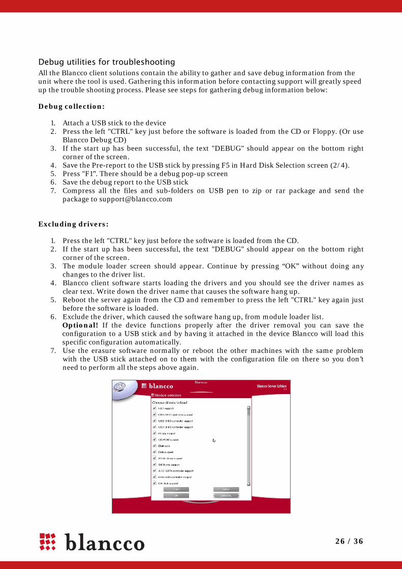
Excluding drivers:
1. Press the left "CTRL" key just before the software is loaded from the CD. 2. If the start up has been successful, the text "DEBUG" should appear on the bottom right
corner of the screen. 3. The module loader screen should appear. Continue by pressing “OK” without doing any
changes to the driver list. 4. Blancco client software starts loading the drivers and you should see the driver names as
clear text. Write down the driver name that causes the software hang up. 5. Reboot the server again from the CD and remember to press the left "CTRL" key again just
before the software is loaded. 6. Exclude the driver, which caused the software hang up, from module loader list.
Optional! If the device functions properly after the driver removal you can save the configuration to a USB stick and by having it attached in the device Blancco will load this specific configuration automatically.
7. Use the erasure software normally or reboot the other machines with the same problem with the USB stick attached on to them with the configuration file on there so you don’t need to perform all the steps above again.

27 / 36
Boot loader error descriptions When loading a Blancco client to the computer memory some problems may occur. The most common ones are listed below. If the error shown on the screen is not listed below, please read: Gathering debug information for [email protected]
Output: Cannot find a valid application image Description: Installation problem, some of the data in the media has been corrupted FIX: New copy of Blancco (e.g. download the CD image again and check the size) Output: Blancco application image damaged, md5sums does not match Description: Broken Blancco application image. In other words data has been corrupted. FIX: New copy of Blancco (e.g. download the CD image again and check the size) Output: Not enough low memory Description: Not enough memory under the 1M area. This usually means that extended bios data
area (XBDA, EBDA) is too large. FIX: Check the bios options and if you cannot make more space in the extended memory
area, please contact us at [email protected].
Deficient BIOS clock Sometimes the BIOS clock can be deficient or the battery may have run out. A broken BIOS clock can lower the resale value of a computer. Blancco software uses the following method to determine if the BIOS clock is broken or not: the software informs the user that the BIOS clock has a defect if the date detected is before 1.1.2003. Erasure can be cancelled or can be continued ignoring the deficient BIOS clock.
Unable to save report notification In Blancco – Data Cleaner v3.7 there was a separate partition in the floppy for saving the reports. This feature is no longer supported in the v4.x product family. Please insert a separate floppy, which is formatted and is not write protected into the floppy drive. If needed the report can be saved also to a USB stick.
Skipping loading modules that cause the system to freeze In some systems drivers can cause loading the software to freeze. Most often there is a problem with USB drivers. It is possible to skip loading the modules, which should remedy the problem. Press CTRL and both shifts while booting to access module selection in text mode and remove any offending modules.
28 / 36
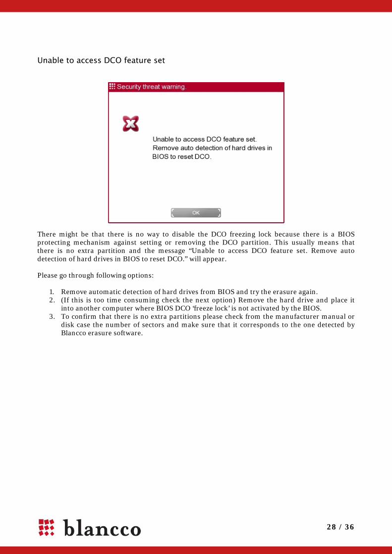
Unable to access DCO feature set
There might be that there is no way to disable the DCO freezing lock because there is a BIOS protecting mechanism against setting or removing the DCO partition. This usually means that there is no extra partition and the message “Unable to access DCO feature set. Remove auto detection of hard drives in BIOS to reset DCO.” will appear. Please go through following options:
1. Remove automatic detection of hard drives from BIOS and try the erasure again. 2. (If this is too time consuming check the next option) Remove the hard drive and place it
into another computer where BIOS DCO ‘freeze lock’ is not activated by the BIOS. 3. To confirm that there is no extra partitions please check from the manufacturer manual or
disk case the number of sectors and make sure that it corresponds to the one detected by Blancco erasure software.

29 / 36
7. ERASURE OF STORAGE SYSTEMS
What should be considered if erasing logical arrays? The dismantling feature is not supported in some RAID adapters and the hard disks are handled and overwritten as logical arrays. The following points ought to be taken into consideration during the erasure process:
• Before starting the erasure in logical arrays confirm that your security policy allows erasure in arrays. From arrays we can’t get the serial numbers of the individual hard disks and therefore the erasure report will not give you valid information. Warning! Blancco does NOT recommend performing erasure in arrays due to a fact that we can’t report which physical device has been erased.
• The logical arrays that are overwritten must be complete and intact. • If the server contains RAID 5 or 6 configurations the overwriting pattern will vary due to
the parity calculations in which the data contents of two or more hard disks are merged into one "parity hard disk". This parity hard disk acts also as back-up data storage. The most important thing is that the data area is overwritten also from the parity hard disk.
• Hot spares (replacement hard disks, in case an online hard disk gets damaged) will not be overwritten with Server/Data Centre Edition as they are not part of the logical array. If the replacement hard disk has not been initialized as part of the array it will normally not contain any data unless it has been used earlier in another hardware configuration for saving data.
• A system partition for RAID information within the first hard disk of a logical array will not be erased since the RAID controller does not enable it. For instance, some RAID adapters contain a meta partition in the beginning of each logical array that contains only RAID configuration data. Erasure of the meta partition can be carried out by attaching the hard disk pack directly to external SCSI controller. After that the RAID controller has been bypassed.
• As the RAID arrays (e.g. AMI MegaRAID) use new I2O I/O architecture, the detection of the arrays is done twice (using normal protocol and I2O protocol) and the I2O arrays should not be erased. In such situation the user needs to select only the normal arrays for the erasure and reject I2O arrays.
• For eXtremeRAID 2000/3000 and AcceleRAID 352/170/160 firmware version 6.00-01 or higher is required. For the eXtremeRAID 1100, firmware version 5.06-0-52 or higher is required. For the AcceleRAID 250, 200, and 150, firmware version 4.06-0-57 or higher is required. For the DAC960PJ and DAC960PG, firmware version 4.06-0-00 or higher is required. For the DAC960PU, DAC960PD, DAC960PL, and DAC960P, either firmware version 3.51-0-04 or higher is required (for dual Flash ROM controllers), or firmware version 2.73-0-00 or higher is required (for single Flash ROM controllers)
Blancco Data Centre edition is the first Blancco data erasure product that is directed to enterprise scale data storage systems. Blancco Data Centre Edition enables the user to perform certified and 100% secure data erasure for directly attached storage enclosures or hard drives through supported host bus adapters. High speed, simultaneous data erasure up to 200+ hard drives provides efficient and fast process for controlled end-of-life storage equipment management.
30 / 36
Erasing RAID configurations with Blancco Server Edition. One of the strengths of Blancco Server Edition is the dismantling feature and it ensures the secure erasure of the entire data surface in all functional hard drives.
Functionality of this feature is to break RAID configurations and erase physical disks separately.
Blancco Server Edition communicates directly with the RAID controller and removes the RAID configuration information. This functionality enables the individual detection of all hard drives (including HDD names and serial numbers).
Important! When erasing RAID Array hardware that Blancco is not able to dismantle/break automatically Blancco highly recommends that the array is dismantled manually from the BIOS of the RAID card or with a manufacturer software.
Blancco Server Edition with dismantling feature can erase the disks that are connected to the following RAID controllers:
AACRAID Controllers Compaq's SMART Array Controllers Compaq's SMART2 Intelligent Disk Array Controllers Adaptec / IBM ServeRAID controllers Mylex DAC960/AcceleRAID/eXtremeRAID PCI RAID Controllers LSI Logic MegaRAID controllers Blancco Server Edition without dismantling feature can erase all disks which are set above, and disks which are connected to the following RAID controllers:
Adaptec I2O RAID and DPT SmartRAID V I2O boards GDT Disk Array/Storage RAID controllers Linux Host Driver for EIDE RAID Adapters IntelliCache SCSI Adapters Software RAID controllers Broadcom (formerly ServerWorks) 3ware RAID controllers Intel/ICP RAID controllers Other devices In this case Blancco Server detects the disks behind the RAID controller as logical arrays. Important! When erasing RAID as logical arrays, disks behind the RAID controller still contains the RAID configuration information. Please make sure that the firmware in your RAID adapter has been updated recently in order to avoid any unnecessary problems with the RAID controller.
31 / 36
Erasing hard drives not detected through RAID adapter Depending on the RAID adapter, server configuration or hard drive connector type, the hard drives might not be detected by Blancco Erasure Software. If you run into such configuration, report it to Blancco and try one of the following suggestions:
1. Attaching hard drives to an integrated SCSI port on a motherboard Normally, the RAID adapter is the reason why hard drives are not detected. In these cases the fastest solution for erasing the hard drives is to bypass the RAID adapter. Most server computers contain either an integrated SCSI port on a motherboard or an additional standard SCSI card. By attaching the hard drive cable to the SCSI port instead of the RAID adapter the hard drives can be detected without any limitations. This operation also allows an individual detection for each hard drive. When the hard drives are detected the erasure can be carried out normally.
2. Removing hard drives and erasing them in another server
If the server machine does not have an additional SCSI port or adapter, the hard drives can also be erased in another server that has a supported RAID/SCSI adapter. Normally, server hard drives use an easy removal mechanism and hot-plug support. This allows the user to easily remove the hard drives without opening the server covers. When using Blancco Server Edition the hard drives with the hot plug functionality can be added to the server even while the software is running in the hard drive detection screen (Step 2/4). All the detected hard drives can be erased without limitations.
Requirements for storage system data erasure 1. Direct access to the physical hard disks through supported Host Bus Adapter (HBA)
a. X86 processor based server b. Supported Host Bus Adapter c. Native hard disk connection to the hard disks or to the hard disk enclosure
2. All active devices (disk processor enclosure or disk controller units) that operate between actual server and hard disks should be bypassed. The terms/names for these active devices are vendor specific.
3. Shut down/disconnect all servers from the system and disconnect Fibre Channel Switches from the system.
4. Possible translation units (paddle cards) that translate the native hard disk protocol communication should be bypassed.
Example case: Please see on the next page a vendor specific example how to process a storage unit where the disks cannot be removed due to the operating system residing inside some of the hard disks.

32 / 36
Procedure for EMC CX400 SAN storage systems These steps and procedures are intended for an advanced user who has a solid foundation of knowledge in server hardware, storage hardware, and operating system installation.
This chapter describes roughly the data erasure process in EMC specific storage system environment. The steps might be different depending on the manufacturer/model.
Make sure that you have a system available with both copper and optical Host Bus Adapter (HBA) – and you need a bootable CD-ROM (this system will be referred as “Blancco”-server”).
Shut down/disconnect all servers from the system and disconnect Fibre Channel Switches from the system.
1. Disconnect all Disk Array Enclosures (DAE) from the Disk Processor Enclosure (DPE) or DAE/OS.
2. Connect first Back End loop (BE) to the Blancco-server (copper). Note. You will only be able to connect one of the paths and one BE loop at a time.
3. Start the Blancco-server with bootable CD-ROM and it will discover all drives in each DAE that is attached to the BE loop. Count the drives listed on the software to make sure all drives are detected.
4. Choose overwriting method. 5. Start Erasure. 6. You will have to perform this on each BE loop one at a time. While the Blancco server is working on DAEs you can prepare the DAE/OS or DPE for erasure.
7. There should not be any RAID Groups, LUNs or Storage Groups left. 8. Create a RAID Group for disks 0-4 (Assumes that operating system is located on first 5
disks) and create a LUN in that (RAID-0 Maximum size). 9. Create another RAID Group for the rest of the disks on the DAE/OS or DPE and create a
LUN in that (RAID-0 Max Size). Erase all disks in every DAEs on all BE loops before continuing. 10. Now you can connect the Blancco server to the system’s Front End (FE)-port. 11. If you have a dual port HBA on the Blancco server then connect the other on SPA (Storage
processor) and the other on SPB and make sure that your LUNs are assigned for different SPs.
12. If you have a single port HBA then connect it to one of the SPs and make sure that all LUNs are on that SP.
13. After discovery of devices you should be able to see those LUNs that you just created on the DAE/OS or DPE.
14. Select the same Erasure method for this erasure as well and start it. 15. Delete RAID Groups and LUN's on the DAE/OS and clear all other settings as well (IP,
Network Name, etc.). For more information on configuring the SAN Storage Systems, please consult your hardware manufacturer.

33 / 36
Erasing the hardware that is not supported by Blancco Blancco Server Edition and Blancco Data Centre Edition support x86 (Intel, AMD, Cyrix etc) based machines. Some servers are using different processor architecture and cannot be erased with these software products. Blancco SPARC Edition can erase Sun SPARC based servers. Servers built on other architectures cannot be erased with the Blancco Erasure Client. Most of these servers are reserving a lot of space and moving them around can be challenging. In addition, there could be many hard drives thus making it inefficient to physically remove the hard drives and erase them in another hardware configuration. Fortunately, HDDs are always the same regardless of the other hardware (i.e. x86/RISC architecture) and Blancco can be used to erase the HDDs by connecting them to another x86-based computer. As a solution, the hard drives can be connected to a supported x86-based machine (erasure station) and erased without the need to remove them physically from the original configuration. The picture below describes how the hard drives from the RISC-based server have been connected to the x86-based server. Note! http://www.blancco.com/presentations/presentations/erasure-station.swf
Note! Starting from version 4.8 Blancco started to support alternative sector sizes including 520, 524 and 528. Only the standard sector size 512 bytes/sector is supported in the 4.7 versions and earlier. In the case of the hard disk using different sector size and you are using an older version than 4.8 the hard disk must be re-formatted to use sector size 512 bytes/sector. Please contact the manufacturer of your hard disk for a proper formatting tool or contact your sales representative and upgrade to current Blancco Erasure Client.
34 / 36
8. CONTACT BLANCCO SERVICE Connection points to Blancco - Service: Phone (only for service package): Service engineers can be reached from a dedicated service number during office hours between 8 am and 6 pm (UTC/GMT +2 hours) excluding public holidays Email and online support forms: Service engineers will respond within 24 hours (only for service package) during weekdays (excluding Finnish public holidays). Enquiries sent during the weekends will get responded to within 72 hours. Technical support: [email protected] Phone and Fax: Sales: +358-207-433-850 Support: +358-207-433-860 Fax: +358-207-433-859 Address: Blancco Ltd. Länsikatu 15 FIN-80110 Joensuu Finland Please visit our homepage (http://www.blancco.com) for more information on our products and our local offices around the world. We are always looking to improve our products. Please let us know if you have any suggestions!

35 / 36
9. LICENSE AGREEMENT Blancco PC Edition, Blancco Server Edition, Blancco Data Centre Edition, Blancco – Asset Manager (“Product”) Version: 4.9 Third-Party License and Copyright Blancco Oy Ltd ("Blancco") and its licensors retain all ownership rights to the Product offered by Blancco and related documentation. Use of the Product and related documentation is governed by this License Agreement for the Product and applicable copyright law. Blancco hereby grants you (“You”) a non-exclusive, restricted license to install and use one copy of the Product only on your computer or on your network server for Your sole use only. The Product may be shared by multiple computers provided that one authorized copy of the Product has been licensed from Blancco for each computer using the Product. You may not sell, rent, license, sub-license, lend or otherwise transfer the Product to any other person or entity. You may not modify, translate, reverse engineer, decompile or disassemble the Product. You may make additional copy of the Product solely for backup purposes. Blancco may revise this documentation from time to time without notice. IN NO EVENT SHALL BLANCCO OR ITS AUTHORIZED DISTRIBUTORS HAVE ANY LIABILITY FOR ANY INDIRECT, INCIDENTAL, SPECIAL, PUNITIVE, EXEMPLARY OR CONSEQUENTIAL DAMAGES (INCLUDING WITHOUT LIMITATION ANY LOSS OF PROFITS OR DATA, BUSINESS INTERUPTION OR OTHER PECUNIARY LOSS) ARISING OUT OF THE USE OR INABILITY TO USE THE PRODUCT, EVEN IF BLANCCO OR ITS AUTHORIZED DISTRIBUTORS HAVE BEEN ADVISED OF THE POSSIBILITY OF SUCH DAMAGES. IN NO EVENT SHALL THE AGGREGATE LIABILITY OF BLANCCO AND ITS AUTHORIZED DISTRIBUTORS (WHETHER IN CONTRACT, WARRANTY, TORT (INCLUDING NEGLICENCE), PRODUCT LIABILITY OR OTHER THEORY) ARISING OUT OF THE USE OR INABILITY TO USE THE PRODUCT EXCEED YOUR PURCHASE PRICE FOR THE PRODUCT. THE PRODUCT AND RELATED DOCUMENTATION IS PROVIDED "AS IS" WITHOUT WARRANTY OF ANY KIND. SHOULD THE PRODUCT PROVE DEFECTIVE IN ANY RESPECT, YOUR SOLE REMEDY IS TO RECEIVE ANOTHER COPY OF THE PRODUCT FROM BLANCCO AT NO CHARGE. ANY REPLACEMENTPRODUCT WILL BE WARRANRTED TO SUBSTANTIALLY PERFORM IN ACCORDANCE WITH THE DOCUMENTATION FOR THE REMAINDER OF THE ORIGINAL WARRANTY PERIOD OR THIRTY (30) DAYS FROM THE DATE OFDELIVERY OF THE SOFTWARE TO YOU, WHICHEVER IS LONGER. BLANCCO AND / OR ITS AUTHORIZED DISTRIBUTORS MAKE, AND YOU RECEIVE, NO WARRANTIES OR CONDITIONS, EXPRESSED, IMPLIED, STATUTORY OR OTHERWISE, OTHER THAN AS EXPRESSLY SET OUT IN THIS AGREEMENT AND BLANCCO AND / OR ITS AUTHORIZED DISTRIBUTORS SPECIFICALLY DISCLAIMS ANY WARRANTY OF MERCHANTIBILITY OR FITNESS FOR A PARTICULAR PURPOSE SOME STATES AND JURISDICTIONS DO NOT ALLOW LIMITATIONS ON IMPLIED WARRANTIES, SO THE ABOVE LIMITATION MAY NOT APPLY TO YOU. THIS LIMITED WARRANTY IS VOID IF THE FAILURE OF THE PRODUCTHAS RESULTED FROM ACCIDENT, ABUSE OR FAILURE TO FOLLOW THE DOCUMENTATION. Without prejudice of any other rights Blancco may terminate this Agreement if you fail to comply with the terms and conditions of this Agreement. Blancco is registered trademark of Blancco Oy Ltd. Other Blancco logos, product names, and service names are also trademarks of Blancco Oy Ltd. Other product and brand names are the exclusive property of their respective owners. The Product and documentation are copyright © 2009 Blancco Oy Ltd. All rights reserved. ==================================================== Portions of the Product are copyright © 1996-2002 The FreeType Project (www.freetype.org). All rights reserved. ==================================================== The Product contains nt-registry library copyright © by Peter Nordahl-Hagen. ==================================================== In portions of the Product freely available and distributable software has been used. That software has been licensed under the separate GNU General public License (GPL or GNU lesser General Public License (LGPL). ==================================================== The Product contains freely available fonts from Baekmuk Font 21 Inc. You are hereby granted permission under all Baekmuk Font 21 propriety rights to use, copy, modify, sublicense, sell, and redistribute the 4 Baekmuk truetype outline fonts for any purpose and without restriction; provided, that this notice is left intact on all copies, of such fonts and that Baekmuk Font 21 trademark is acknowledged as shown below on all copies of the 4 Baekmuk truetype fonts. BAEKMUK BATANG is a registered trademark of Baekmuk Font 21 Inc. BAEKMUK GULIM is a registered trademark of Baekmuk Font 21 Inc. BAEKMUK DOTUM is a registered trademark of Baekmuk Font 21 Inc. BAEKMUK HEADLINE is a registered trademark of Baekmuk Font 21 Inc. ==================================================== This product contains freely available fonts of Microsoft that has the following separate license: Microsoft TrueType Fonts ==================================================== The freely available and distributable third party software that have been used, and down load links to the source code, can be found from: http://www.blancco.com/downloads/source/. For further licensing issues, please contact us by e-mail at [email protected] ====================================================

36 / 36
36 / 36